Embed Size (px)
Citation preview
Dave Kamp’s book ofIH Cub Cadet Modifications:
U-joint Driveshaft

2
Dave Kamp’s magic book of International Harvester Cub Cadet Modifications
WHAT IS THIS ‘MODIFICATION’, AND WHAT PROMPTED THE DESIGN?
First Answer: necessity. These darned pin-couplers worked, and most are still in service, but they wear andfail at what I consider to be a ‘consumeable’ rate. Frankly, I hate consumable parts that can’t be removedthrough a drain-plug, using a catch-pan... and can’t be replaced using a funnel and a few paper towels... Iespecially hate consumable parts that can’t be changed in under 4 minutes. Oil and air filters, spark plugs,fuel, and oil are enough of a PITA, I’d rather put my tools to WORK, rather than WORK on them. Not only amI a busybody, with an eternal to-do list, I’m also lazy- hate doing things that shouldn’t’ve had to be done in theFIRST PLACE.
You’ll find, in reading through, that not only do these modifications improve the mechanical considerations ofthe machine, there’s a few aspects where it actually makes maintenance easier, faster, etc... Again- I’m abusybody, always working on something, but I HATE having to work on something that I just fixed the otherday.
May God bless Harold Schramm for introducing this Cub Cadet to the world- without it, I’d have no reason tobe documenting what I’ve done, but worse yet, I’d have no Cubs to help me do all the work that I’d ratherTHEY bear the heaviest burdon of. Harold was undoubtedly one of the nicest, sharpest guys I’ve ever met,and an extremely astute engineer in both terms of product design excellence, but also in Quality Control.There’s three aspects of Quality Control- first being... getting quality HIGH enough to get customersatsifaction... next, getting quality NO HIGHER THAN what’s necessary to meet the marketplace with acompetetive product (that’s profit). The LAST, is designing something so that it hits the UPPER level, at thecost of the LOWER. Example being: excess precision. Peoplethink that manufacturing parts is expensive... it’s not... butmanufacturing with PRECISION is VERY expensive. If you designsomething that requires substantial attention to precision, it may bea nice product, but it’ll be not only too expensive to be competetive,it’ll also be too finicky when in a varying environment. Agriculturalenvironments being what they are, the LEAST amount of precisionis typically the best. Putting all these things together is what old-school engineers refer to as making ‘successful designcompromise’.
In the realm of the General Consumer market, There’s only a fewnatural weaknesses to the Cub Cadet... the coupler is one ofthem... there’s a few other minor things. We Cub Cadet enthusiasts, however, exceed the realm of “JoeConsumer” who was purchasing these things new between the 1960’s and ‘80’s... we hang incredible amountsof ballast, hop up the engines, fit implements, and thrash them like a red-headed stepchild... and thesemachines soldier on through it all, like they were intended to from the git-go. In a sick... perhaps sado-masochistic sorta way, we love it... but every so often, the steed gets an Achilles Heel. I purposely go lookingfor these ‘heels’, and find ways of resolving ‘em.
Follow along as I show you what, and how I’ve modified on my IHCCs to make some of the natural designcompromises a little bit less compromising. As you’re looking, keep in mind that Harold DID see most of thesemodifications before passing on, and noted to me that... if during his tenure on the Design Staff, had some ofthe materials and products that I employ been available, as well as the insight into long-term wear and useweaknesses, they likely would’ve made some of the same decisions I did. I consider that one of the mostrespectful comments one could ever recieve, but it isn’t warranted- hindsight engineering is much easier todo, than foresight engineering.
3
Dave Kamp’s magic book of International Harvester Cub Cadet Modifications
ABOUT THESE U-JOINTS
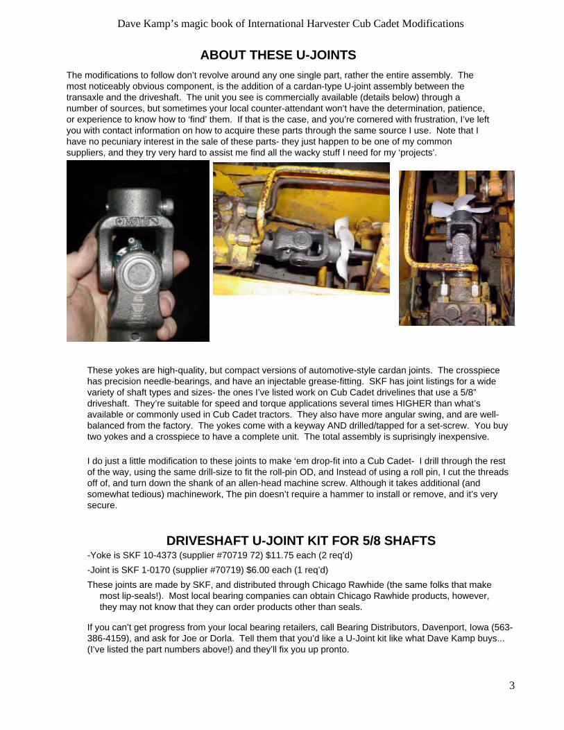
The modifications to follow don’t revolve around any one single part, rather the entire assembly. Themost noticeably obvious component, is the addition of a cardan-type U-joint assembly between thetransaxle and the driveshaft. The unit you see is commercially available (details below) through anumber of sources, but sometimes your local counter-attendant won’t have the determination, patience,or experience to know how to ‘find’ them. If that is the case, and you’re cornered with frustration, I’ve leftyou with contact information on how to acquire these parts through the same source I use. Note that Ihave no pecuniary interest in the sale of these parts- they just happen to be one of my commonsuppliers, and they try very hard to assist me find all the wacky stuff I need for my ‘projects’.
These yokes are high-quality, but compact versions of automotive-style cardan joints. The crosspiecehas precision needle-bearings, and have an injectable grease-fitting. SKF has joint listings for a widevariety of shaft types and sizes- the ones I’ve listed work on Cub Cadet drivelines that use a 5/8”driveshaft. They’re suitable for speed and torque applications several times HIGHER than what’savailable or commonly used in Cub Cadet tractors. They also have more angular swing, and are well-balanced from the factory. The yokes come with a keyway AND drilled/tapped for a set-screw. You buytwo yokes and a crosspiece to have a complete unit. The total assembly is suprisingly inexpensive.
I do just a little modification to these joints to make ‘em drop-fit into a Cub Cadet- I drill through the restof the way, using the same drill-size to fit the roll-pin OD, and Instead of using a roll pin, I cut the threadsoff of, and turn down the shank of an allen-head machine screw. Although it takes additional (andsomewhat tedious) machinework, The pin doesn’t require a hammer to install or remove, and it’s verysecure.
DRIVESHAFT U-JOINT KIT FOR 5/8 SHAFTS-Yoke is SKF 10-4373 (supplier #70719 72) $11.75 each (2 req’d)
-Joint is SKF 1-0170 (supplier #70719) $6.00 each (1 req’d)
These joints are made by SKF, and distributed through Chicago Rawhide (the same folks that makemost lip-seals!). Most local bearing companies can obtain Chicago Rawhide products, however,they may not know that they can order products other than seals.
If you can’t get progress from your local bearing retailers, call Bearing Distributors, Davenport, Iowa (563-386-4159), and ask for Joe or Dorla. Tell them that you’d like a U-Joint kit like what Dave Kamp buys...(I’ve listed the part numbers above!) and they’ll fix you up pronto.
4
Dave Kamp’s magic book of International Harvester Cub Cadet Modifications
DRILLING YOKES FOR PINS
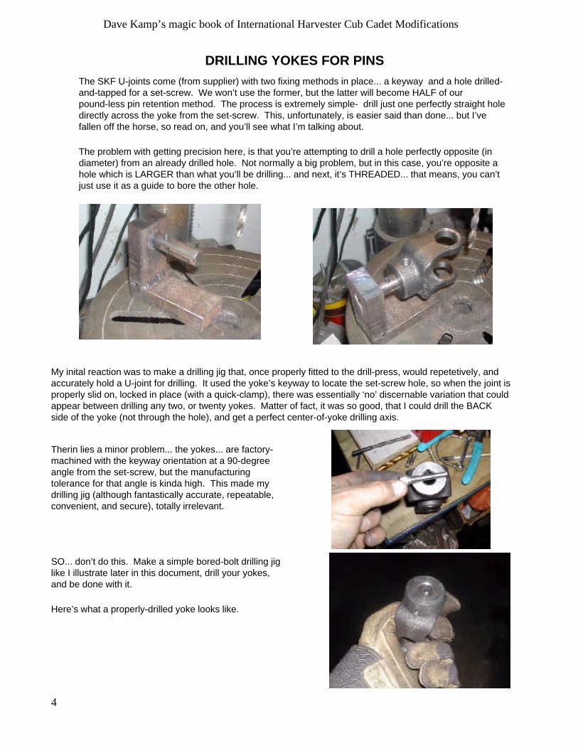
The SKF U-joints come (from supplier) with two fixing methods in place... a keyway and a hole drilled-and-tapped for a set-screw. We won’t use the former, but the latter will become HALF of ourpound-less pin retention method. The process is extremely simple- drill just one perfectly straight holedirectly across the yoke from the set-screw. This, unfortunately, is easier said than done... but I’vefallen off the horse, so read on, and you’ll see what I’m talking about.
The problem with getting precision here, is that you’re attempting to drill a hole perfectly opposite (indiameter) from an already drilled hole. Not normally a big problem, but in this case, you’re opposite ahole which is LARGER than what you’ll be drilling... and next, it’s THREADED... that means, you can’tjust use it as a guide to bore the other hole.
My inital reaction was to make a drilling jig that, once properly fitted to the drill-press, would repetetively, andaccurately hold a U-joint for drilling. It used the yoke’s keyway to locate the set-screw hole, so when the joint isproperly slid on, locked in place (with a quick-clamp), there was essentially ‘no’ discernable variation that couldappear between drilling any two, or twenty yokes. Matter of fact, it was so good, that I could drill the BACKside of the yoke (not through the hole), and get a perfect center-of-yoke drilling axis.
Therin lies a minor problem... the yokes... are factory-machined with the keyway orientation at a 90-degreeangle from the set-screw, but the manufacturingtolerance for that angle is kinda high. This made mydrilling jig (although fantastically accurate, repeatable,convenient, and secure), totally irrelevant.
SO... don’t do this. Make a simple bored-bolt drilling jiglike I illustrate later in this document, drill your yokes,and be done with it.
Here’s what a properly-drilled yoke looks like.
5
Dave Kamp’s magic book of International Harvester Cub Cadet Modifications
INSTALLING THE U-JOINT DRIVELINE
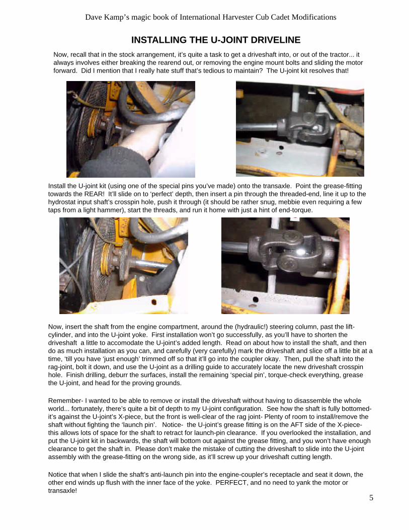
Now, recall that in the stock arrangement, it’s quite a task to get a driveshaft into, or out of the tractor... italways involves either breaking the rearend out, or removing the engine mount bolts and sliding the motorforward. Did I mention that I really hate stuff that’s tedious to maintain? The U-joint kit resolves that!
Install the U-joint kit (using one of the special pins you’ve made) onto the transaxle. Point the grease-fittingtowards the REAR! It’ll slide on to ‘perfect’ depth, then insert a pin through the threaded-end, line it up to thehydrostat input shaft’s crosspin hole, push it through (it should be rather snug, mebbie even requiring a fewtaps from a light hammer), start the threads, and run it home with just a hint of end-torque.
Now, insert the shaft from the engine compartment, around the (hydraulic!) steering column, past the lift-cylinder, and into the U-joint yoke. First installation won’t go successfully, as you’ll have to shorten thedriveshaft a little to accomodate the U-joint’s added length. Read on about how to install the shaft, and thendo as much installation as you can, and carefully (very carefully) mark the driveshaft and slice off a little bit at atime, ‘till you have ‘just enough’ trimmed off so that it’ll go into the coupler okay. Then, pull the shaft into therag-joint, bolt it down, and use the U-joint as a drilling guide to accurately locate the new driveshaft crosspinhole. Finish drilling, deburr the surfaces, install the remaining ‘special pin’, torque-check everything, greasethe U-joint, and head for the proving grounds.
Remember- I wanted to be able to remove or install the driveshaft without having to disassemble the wholeworld... fortunately, there’s quite a bit of depth to my U-joint configuration. See how the shaft is fully bottomed-it’s against the U-joint’s X-piece, but the front is well-clear of the rag joint- Plenty of room to install/remove theshaft without fighting the ‘launch pin’. Notice- the U-joint’s grease fitting is on the AFT side of the X-piece-this allows lots of space for the shaft to retract for launch-pin clearance. If you overlooked the installation, andput the U-joint kit in backwards, the shaft will bottom out against the grease fitting, and you won’t have enoughclearance to get the shaft in. Please don’t make the mistake of cutting the driveshaft to slide into the U-jointassembly with the grease-fitting on the wrong side, as it’ll screw up your driveshaft cutting length.
Notice that when I slide the shaft’s anti-launch pin into the engine-coupler’s receptacle and seat it down, theother end winds up flush with the inner face of the yoke. PERFECT, and no need to yank the motor ortransaxle!
6
Dave Kamp’s magic book of International Harvester Cub Cadet Modifications
MAKING A DRIVESHAFT WITH RAG-JOINT END
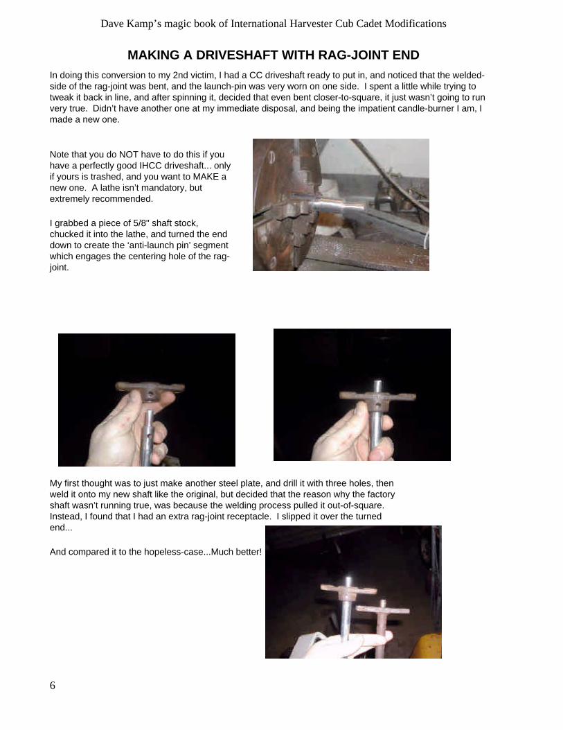
In doing this conversion to my 2nd victim, I had a CC driveshaft ready to put in, and noticed that the welded-side of the rag-joint was bent, and the launch-pin was very worn on one side. I spent a little while trying totweak it back in line, and after spinning it, decided that even bent closer-to-square, it just wasn’t going to runvery true. Didn’t have another one at my immediate disposal, and being the impatient candle-burner I am, Imade a new one.
Note that you do NOT have to do this if youhave a perfectly good IHCC driveshaft... onlyif yours is trashed, and you want to MAKE anew one. A lathe isn’t mandatory, butextremely recommended.
I grabbed a piece of 5/8" shaft stock,chucked it into the lathe, and turned the enddown to create the ‘anti-launch pin’ segmentwhich engages the centering hole of the rag-joint.
My first thought was to just make another steel plate, and drill it with three holes, thenweld it onto my new shaft like the original, but decided that the reason why the factoryshaft wasn’t running true, was because the welding process pulled it out-of-square.Instead, I found that I had an extra rag-joint receptacle. I slipped it over the turnedend...
And compared it to the hopeless-case...Much better!

7
Dave Kamp’s magic book of International Harvester Cub Cadet Modifications
Now, in the stock arrangement, it’s quite a task to get the shaft to go into, and out of the tractor. I want to beable to do it without having to disassemble the whole world... fortunately, there’s quite a bit of depth to my U-joint configuration. So I run the shaft from the engine compartment, around the (hydraulic!) steering column,past the lift-cylinder, and into the U-joint yoke.
Notice- the shaft is fully bottomed against the U-joint’s X-piece, but the front is well-clear of the rag joint-Plenty of room to install/remove the shaft. Notice- the U-joint’s grease fitting is on the AFT side of the X-piece- this allows lots of space for the shaft to retract for launch-pin clearance.
But when I slide the shaft’s anti-launch pin into the engine-coupler’s receptacle and seat it down, the other endwinds up flush with the inner face of the yoke. PERFECT!
And the answer you’ve all been waiting for... (or mebbie not)... the dimensions;
8
Dave Kamp’s magic book of International Harvester Cub Cadet Modifications
MAKING A RAG-JOINT COUPLER
Half of this modification is about moving the rag-joint coupling up to the front (engine) end of the driveshaft.Later (QuietLine) tractors came with a rag-joint up front, most likely for several factors, including more‘compliance’ required to suit the soft-mount engine cradle, and obvious wear-concerns on the drive-pinarrangement. A less obvious bonus to moving the rag-joint to the front, is that the hydrostat cooling fan ismuch less ‘obstructed’, likely increasing cooling airflow over the hydrostat housing.
Knowing that the QuietLines came with this ‘alternative’ drive method, I’ve been asked why I didn’t just go findQL parts. First answer, is that I’m cheap, and QL drive couplers aren’t... the next is that all the necessaryparts were right there (in the factory-stock tractor), and the last answer is that when it’s a quarter-of-two (AM)and I want a running tractor before going to bed, I use what I’ve got.
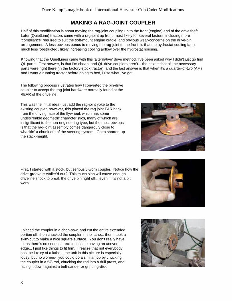
The following process illustrates how I converted the pin-drivecoupler to accept the rag-joint hardware normally found at theREAR of the driveline.
This was the initial idea- just add the rag-joint yoke to theexisting coupler, however, this placed the rag joint FAR backfrom the driving face of the flywheel, which has someundesireable geometric characteristics, many of which areinsignificant to the non-engineering type, but the most obviousis that the rag-joint assembly comes dangerouly close towhackin’ a chunk out of the steering system. Gotta shorten-upthe stack-height.
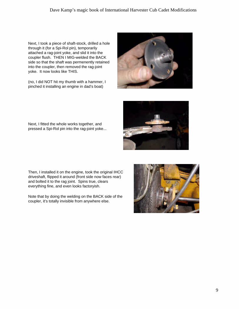
First, I started with a stock, but seriously-worn coupler. Notice how thedrive-groove is waller’d out? This much slop will cause enoughdriveline shock to break the drive pin right off... even if it’s not a bitworn.
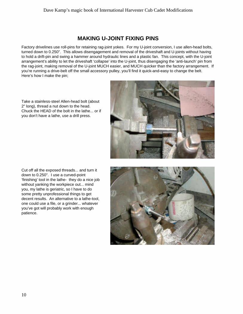
I placed the coupler in a chop-saw, and cut the entire extendedportion off, then chucked the coupler in the lathe... then I took askim-cut to make a nice square surface. You don’t really haveto, as there’s no serious precision lost to having an unevenedge... I just like things to fit firm. I realize that not everybodyhas the luxury of a lathe... the unit in this picture is especiallylousy, but no worries- you could do a similar job by chuckingthe coupler in a 5/8 rod, chucking the rod into a drill press, andfacing it down against a belt-sander or grinding-disk.
9
Dave Kamp’s magic book of International Harvester Cub Cadet Modifications
Next, I took a piece of shaft-stock, drilled a holethrough it (for a Spi-Rol pin), temporarilyattached a rag-joint yoke, and slid it into thecoupler flush. THEN I MIG-welded the BACKside so that the shaft was permenently retainedinto the coupler, then removed the rag-jointyoke. It now looks like THIS.
(no, I did NOT hit my thumb with a hammer, Ipinched it installing an engine in dad’s boat)
Next, I fitted the whole works together, andpressed a Spi-Rol pin into the rag-joint yoke...
Then, I installed it on the engine, took the original IHCCdriveshaft, flipped it around (front side now faces rear)and bolted it to the rag joint. Spins true, clearseverything fine, and even looks factoryish.
Note that by doing the welding on the BACK side of thecoupler, it’s totally invisible from anywhere else.
10
Dave Kamp’s magic book of International Harvester Cub Cadet Modifications
MAKING U-JOINT FIXING PINS
Factory drivelines use roll-pins for retaining rag-joint yokes. For my U-joint conversion, I use allen-head bolts,turned down to 0.250". This allows disengagement and removal of the driveshaft and U-joints without havingto hold a drift-pin and swing a hammer around hydraulic lines and a plastic fan. This concept, with the U-jointarrangement’s ability to let the driveshaft ‘collapse’ into the U-joint, thus disengaging the ‘anti-launch’ pin fromthe rag-joint, making removal of the U-joint MUCH easier, and MUCH quicker than the factory arrangement. Ifyou’re running a drive-belt off the small accessory pulley, you’ll find it quick-and-easy to change the belt.Here’s how I make the pin;
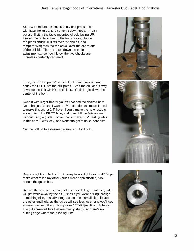
Take a stainless-steel Allen-head bolt (about2" long), thread a nut down to the head.Chuck the HEAD of the bolt in the lathe... or ifyou don’t have a lathe, use a drill press.
Cut off all the exposed threads... and turn itdown to 0.250". I use a curved-point‘finishing’ tool in the lathe- they do a nice jobwithout yanking the workpiece out... mindyou, my lathe is geriatric, so I have to dosome pretty unprofessional things to getdecent results. An alternative to a lathe-tool,one could use a file, or a grinder... whateveryou’ve got will probably work with enoughpatience.

11
Dave Kamp’s magic book of International Harvester Cub Cadet Modifications
When you’re done, it looks like this: But you’ll see that when installed, there’s a littleinterferance between the bottom edge of theAllen head and the yoke arm. In this case, I...
Chuck the freshly-turned end of the bolt into thedrill-press, and chamfer the underside of thebolt with a file, and brighten it up with a sandingdisk in one of my 4.5" disk-grinders...
...and while I’m at it, I wipe off the casting markalong the yoke’s edge, as it fouls the bolt a little,too... and the end result looks like:

12
Dave Kamp’s magic book of International Harvester Cub Cadet Modifications
MAKING A DRILLING-GUIDE
While building up a U-joint driveline for another project, I ran into an interesting challenge...On previous U-joints, I used a tool in which the yoke slid onto a section of key’d shaft... itheld the yoke with the set-screw opening at a 90 angle to the table, centered-and-squarewith the drill. But on THIS particular yoke, the keyway was cut slightly off... by about 1degree. Probably had the bit in the machine slip that day. I didn’t want to drill this using myconventional tool, as the pin wouldn’t fit properly with the driveline assembled.
So I made a new drill-guide just do deal with this scenario... and to illustrate how somesimple concepts can allow one to make a precise tool in even a limited garage. Note thatthis technique will work for ANY bolt-center-finding application, not just drilling yokes.
To do this task, you’ll need to raid your ‘junk box’. If you don’t have a ‘junk box’, yourgarage is seriously challenged... start by roving the streets, gathering up your neighbors’trash, hopefully you’ll find some old appliances in there, mebbie some broken tools, abeercan or two that’s still got a swig-left... anyway, disassemble it, and throw all the piecesin an old wooden crate. Slide it under your workbench, and refer to it as your ‘junk box’.From this point on, never throw anything away until you’ve disassembled it and thrown allthe pieces in your ‘junk box’. If the box becomes full, start a new one. Continue adding onto your garage until you can’t make more space for more junk boxes.
So now we employ the junk-box. First, I found a bolt which threaded intothe yoke properly. This one is a Grade 5 bolt... (I don’t recommend youtrying this stunt with a Grade 8, unless you’ve got lots of sharp drill-bitsthat you’d like to torture). I quick chuck-it in the drill and scrub the top ofthe head with the 4" disk grinder to take the markings off and leave asmooth surface
What I’m gonna do, is drill down the CENTER of this bolt, so when I’mdone, I can use the drilled-bolt as a guide to drill a concentric hole at theOPPOSITE side of the yoke. Better yet, since I’ve got a lathe, and y’allknow I’m not ‘fraid to use it, I’m gonna do this task WITHOUT using aLATHE.... yep, you can do it with your own tools!
Again, we’ll need to hit the junk-box. You’ll need an drillchuck. I had an old Craftsman cordless drill that’d long sincebit the dust, but still had some good parts- I ‘liberated’ thekeyless-chuck (oooh... deluxe garage tool!). I grabbed mybox of taps, and threaded a few in, to determine what thechuck’s thread-size was... turns out, this one was 3/8-24.Went to my junk box, and dug out a stud from who-knows-what... but 3/8-24 on one end, 3/8-16 on the other, and justabout the right length, too. I also found a fender-washer anda funk y nut/washer assembly that probably came from theseatbelt assembly of a FORD pickup I scrapped 15 yearsago.
13
Dave Kamp’s magic book of International Harvester Cub Cadet Modifications
So now I’ll mount this chuck to my drill-press table,with jaws facing up, and tighten it down good. Then Iput a drill bit in the table-mounted chuck, facing UP.I swing the table to line up the two chucks, plungethe press chuck ‘till it fits over the drill bit, andtemporarily tighten the top chuck over the sharp-endof the drill bit. Then I tighten down the tableadjustments... so now I know the two chucks aremore-less perfectly centered.
Then, loosen the press’s chuck, let it come back up, andchuck the BOLT into the drill press. Start the drill and slowlyadvance the bolt ONTO the drill bit... it’ll drill right-down-the-center of the bolt.
Repeat with larger bits ‘till you’ve reached the desired bore.Note that just ‘cause I want a 1/4" hole, doesn’t mean I needto make this with a 1/4" hole- I could make the hole just bigenough to drill a PILOT hole, and then drill the finish-sizeswithout using a guide... or you could make SEVERAL guides.In this case, I was lazy, and went straight to finish-bore size.
Cut the bolt off to a desireable size, and try it out...
Boy- it’s right-on. Notice the keyway looks slightly rotated? Yep-that’s what foiled my other (much more sophisticated) tool,hence, the guide-bolt.
Realize that as one uses a guide-bolt for drilling... that the guidewill get worn-away by the bit, just as if you were drilling throughsomething else. It’s advantageous to use a small bit to locatethe other-end hole, as the guide will see less wear, and you’ll geta more precise drilling. IN my case 1/4" did just fine... I cheat-Iv’e got some drill bits that are mostly shank, so there’s nocutting edge where the bushing runs.


![Parts Manual - Cub Cadet Parts, Cub Parts, Troy-Bilt Parts ... 769-01034a.pdfTRACTOR Model Number GT 2554 Parts Manual CUB CADET LLC P.O. BOX 361131 CLEVELAND, OHIO 44136-0019 [] PRINTED](https://img.dokumen.tips/doc/110x75/5fce373361202357c916774b/parts-manual-cub-cadet-parts-cub-parts-troy-bilt-parts-769-01034apdf-tractor.jpg)