Embed Size (px)
Citation preview

System-On-Chip (SOC) Technologies
Datasheet - Encoder Modules (HD and 4k) V.4.1, 2016
© System-On-Chip Technologies Inc. www.soctechnologies.com Page 1
®
Datasheet - Encoder Modules
System-On-Chip (SOC) Technologies
Table of Contents
1. Product Overview
2. Connecting the Module to a User PCB
3. MCM-1000S Module
3.1 Block Diagram and Major Components
3.2 Standard Encoder Modules based on MCM-1000S
3.3 Pin Assignments and Electrical Properties of MCM-1000S
3.4 Data Signal format
3.5 Power Rails of MCM-1000S
3.6 Power Requirement
3.7 Power Supply Amperage
4. MCM-1000A Module
4.1 Block Diagram and Major Components
4.2 Standard Encoder Modules based on MCM-1000A
4.3 Pin Assignments and Electrical Properties of MCM-1000A
4.4 Data Signal format
4.5 Power Rails of MCM-1000A
4.6 Power Requirement
4.7 Power Supply Amperage
5. MCM-1000Z Module
5.1 Block Diagram and Major Components
5.2 Standard Encoder Modules based on MCM-1000Z
5.3 Pin Assignments and Electrical Properties of MCM-1000Z
5.4 Data Signal format
5.5 Power Rails of MCM-1000Z
5.6 Power Requirement
5.7 Power Supply Amperage
6. Carrier Board PCB Reference Designs
6.1 FMC-MCM-1000 Evaluation Board
6.2 VTR-2000 Evaluation Board
6.3 VTR-4000 Evaluation Board
7. Ordering Information
Appendix-A MCM-1000S Edge Connector Schematics
Appendix-B MCM-1000A Edge Connector Schematics
Appendix-C MCM-1000Z Edge Connector Schematics
System-On-Chip (SOC) Technologies
Datasheet - Encoder Modules (HD and 4k) V.4.1, 2016
© System-On-Chip Technologies Inc. www.soctechnologies.com Page 2
®
1. Product Overview
The SOC MPEG Codec Modules are small all-in-one hardware modules that connect to a user PCB through a
standard DDR3 SODIMM connector for video/audio compression, decompression, and transcoding functions.
Current available modules are:
1. MCM-1000S – Spartan-5 XC6SLX150 (HD up to 30 frames per second);
2. MCM-1000A – Artix-7 XC7A200T (HD up to 60 frames per second);
3. MCM-1000Z – Zynq-7 XC7Z035/045 (for 4k modules).
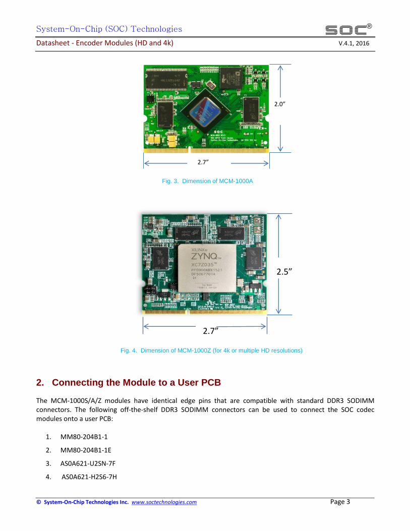
Fig. 1 shows a photo of the modules. Fig. 2-4 shows the dimensions of MCM-1000S, MCM-1000A, and MCM-
1000Z respectively.
Fig.1. SOC Codec Modules
Fig. 2. Dimension of MCM-1000S
2.7”
1.7”
System-On-Chip (SOC) Technologies
Datasheet - Encoder Modules (HD and 4k) V.4.1, 2016
© System-On-Chip Technologies Inc. www.soctechnologies.com Page 3
®
Fig. 3. Dimension of MCM-1000A
Fig. 4. Dimension of MCM-1000Z (for 4k or multiple HD resolutions)
2. Connecting the Module to a User PCB
The MCM-1000S/A/Z modules have identical edge pins that are compatible with standard DDR3 SODIMM connectors. The following off-the-shelf DDR3 SODIMM connectors can be used to connect the SOC codec modules onto a user PCB:
1. MM80-204B1-1
2. MM80-204B1-1E
3. AS0A621-U2SN-7F
4. AS0A621-H2S6-7H
2.7”
2.5”
2.7”
2.0”

System-On-Chip (SOC) Technologies
Datasheet - Encoder Modules (HD and 4k) V.4.1, 2016
© System-On-Chip Technologies Inc. www.soctechnologies.com Page 4
®
Fig. 5 shows a photo of a standard 204 pin DDR3 SODIMM PCB connector. Refer to the datasheet of the connector used for the physical dimension and PCB design requirements.
Fig. 5 A photo of the standard 204 pin DDR3 SODIMM connector
3. MCM-1000S Module
3.1 Block Diagram and Major Components
The MCM-1000S is a module based on the Xilinx Spartan-6 XC6SLX150 FPGA and a BlackFin BF512 DSP. The
FPGA is used for video encoding (or decoding), and the DSP is used for audio encoding (or decoding). The SOC
video encoder (or decoder) and the audio encoder (or decoder) IP cores are stored in the flash memory, to allow
the module to function as an encoder (or decoder) on booting. Fig. 6 shows a block diagram and major
components of the MCM-1000S.
Fig. 6. MCM-1000S block diagram and major components
Spartan-6 XC6SLX150
DDR3 #1 MT41J128M16JT
DDR3 #2 MT41J128M16JT
DSP BF512KB
CZ
SD-RAM MT48LC32M16A2TG
N25Q128A13EF740F
MM80-204B1-1 Compatible Connector
Power rails: 1.2v, 1.3v, 1.5v, 2.5v, and 3.3v

System-On-Chip (SOC) Technologies
Datasheet - Encoder Modules (HD and 4k) V.4.1, 2016
© System-On-Chip Technologies Inc. www.soctechnologies.com Page 5
®
3.2 Standard Encoder Modules Based on MCM-1000S
Using the SOC H.264 and MPEG-2 video/audio encoder (or decoder) IP cores, the MCM-1000S can be configured
into a series of encoder (or decoder) modules. Table-1 lists six examples of standard H.264 and MPEG2 encoder
modules. Refer to the Module Selection Guide for more encoder modules offered by SOC based on the MCM-
1000S. Non-standard modules are also possible according to user requirement, with normally a minimum order
quantity (MOQ).
Encoders based on the MCM-1000S module can reach up 1080@30 resolution. Encoder modules of higher
resolutions, such as 1080@60, are based on MCM-1000A (Atrix-7 FPGA) and/or MCM-1000Z (Zynq-7 FPGA),
which are detailed in Section 4 of this document.
The MCM-1000S can also be configured into decoders. The details of the decoder modules are provided in the
Datasheet - Decoder Modules.
Table-1 Examples of standard encoder modules based on MCM-1000S
Product # Specifications Standard Profile Resolution Chroma Precision Frame Rate Audio
EC-VA-H264-8b-30-1080-MS H.264 up to High up to 1080i/p 4:2:0/4:2:2 8 bits up to 30fps AAC or MPEG2 Layer-2 EC-VA-H264-10b-30-1080-MS H.264 up to High up to 1080i/p 4:2:0/4:2:2 up to 10bits up to 30fps AAC or MPEG2 Layer-2 EC-V-H264-8b-30-1080-MS H.264 up to High up to 1080i/p 4:2:0/4:2:2 8 bits up to 30fps no EC-V-H264-10b-30-1080-MS H.264 up to High up to 1080i/p 4:2:0/4:2:2 up to 10 bits up to 30fps no EC-VA-MPEG2-8b-30-1080-MS MPEG2 up to High up to 1080i/p 4:2:0/4:2:2 8 bits up to 30fps AAC or MPEG2 Layer-2 EC-V-MPEG2-8b-30-1080-MS MPEG2 up to High up to 1080i/p 4:2:0/4:2:2 8 bits up to 30fps no
3.3 Pin Assignments and Electrical Properties of MCM-1000S
Table-2 lists the pin assignments for the standard encode modules based on the FMC-MCM-1000S. Pin
Assignment for encoder modules, decoder modules, and transcoder module based on MCM-1000S, are different.
However the pin assignments within a module type, such as all encoders listed in Table-1, are the same. For
example, the MPEG2 encoder and H264 encoder modules have the same pin assignments.
The Schematics of MCM-1000S edge connector are attached in Appendix-A of this document, which shows the
pin numbers for data, clock, and power. The FPGA (Spartan-6 XC6SLX150) pins names connected to the edge
pins are also displayed in the schematics. It is noticed that the encoder modules, such as listed in Table-1, use
only some of the pins that are connected to the FPGA. These assigned pins are listed in Table-2, below.
Table-2 also lists the FPGA pin numbers for the edge pins assigned to the standard encoder modules (listed in
Table-1). Refer to the Spartan-6 XC6SLX150 Datasheet for the FPGA pins. The Spartan-6 datasheet provides
further information regarding the use of these pins, if required (normally not needed).

System-On-Chip (SOC) Technologies
Datasheet - Encoder Modules (HD and 4k) V.4.1, 2016
© System-On-Chip Technologies Inc. www.soctechnologies.com Page 6
®
Table 2: Encoder Module Pin Assignment for MCM-1000S
Description MCM-1000S Edge Connector Pin #
(Refer to schematics in Appendix-A) Direction FPGA Pin # Voltage IO Standard
Video Clock 113 Input C11 3.3v LVCMOS33
Video Horizontal Sync 84 Input W6 3.3v LVCMOS33
Video Vertical Sync 127 Input Y6 3.3v LVCMOS33
Video Display Enable 97 Input Y7 3.3v LVCMOS33
Video Data Luma[0] 94 Input AA16 3.3v LVCMOS33
Video Data Luma[1] 96 Input A14 3.3v LVCMOS33
Video Data Luma[2] 98 Input AA18 3.3v LVCMOS33
Video Data Luma[3] 100 Input AB18 3.3v LVCMOS33
Video Data Luma[4] 102 Input C9 3.3v LVCMOS33
Video Data Luma[5] 104 Input A9 3.3v LVCMOS33
Video Data Luma[6] 106 Input A8 3.3v LVCMOS33
Video Data Luma[7] 108 Input B8 3.3v LVCMOS33
Video Data Luma[8] 110 Input AA6 3.3v LVCMOS33
Video Data Luma[9] 112 Input AB6 3.3v LVCMOS33
Video Data Chroma[0] 99 Input AA14 3.3v LVCMOS33
Video Data Chroma[1] 101 Input AB14 3.3v LVCMOS33
Video Data Chroma[2] 103 Input B18 3.3v LVCMOS33
Video Data Chroma[3] 109 Input A18 3.3v LVCMOS33
Video Data Chroma[4] 111 Input AB15 3.3v LVCMOS33
Video Data Chroma[5] 117 Input B16 3.3v LVCMOS33
Video Data Chroma[6] 119 Input Y15 3.3v LVCMOS33
Video Data Chroma[7] 121 Input A16 3.3v LVCMOS33
Video Data Chroma[8] 123 Input AB16 3.3v LVCMOS33
Video Data Chroma[9] 125 Input B14 3.3v LVCMOS33
SPDIF Audio 140 Input A19 1.5v LVCMOS15
Transport Stream Buffer Ready 142 Output F7 1.5v LVCMOS15
Transport Stream Clock 166 Output A10 3.3v LVCMOS33
Transport Stream Data Valid 148 Output G6 1.5v LVCMOS15
Transport Stream Data[0] 150 Output H17 1.5v LVCMOS15
Transport Stream Data[1] 152 Output H18 1.5v LVCMOS15
Transport Stream Data[2] 154 Output G13 1.5v LVCMOS15
Transport Stream Data[3] 156 Output H12 1.5v LVCMOS15
Transport Stream Data[4] 158 Output G15 1.5v LVCMOS15
Transport Stream Data[5] 160 Output G16 1.5v LVCMOS15
Transport Stream Data[6] 162 Output H8 1.5v LVCMOS15
Transport Stream Data[7] 164 Output J7 1.5v LVCMOS15
Transport Stream Start Code 142 Output E4 1.5v LVCMOS15
Uart_tx 38 Output G4 1.5v LVCMOS15
Uart_rx 40 Input F3 1.5v LVCMOS15

System-On-Chip (SOC) Technologies
Datasheet - Encoder Modules (HD and 4k) V.4.1, 2016
© System-On-Chip Technologies Inc. www.soctechnologies.com Page 7
®
3.4 Signal Format of Data Pins
3.4.1 Clock Signal (Input)
The video clock signal (pin 105) varies according to the resolution of the video input. The following are the clock
frequencies for standard video resolutions:
1. 27MHz, for SD resolution
2. 74.25MHz, for 720@60 and 1080@30
3.4.2 Video Data Signals (input)
The input to the encoder module, H.264 or MPEG-2 listed in Table-1, is raw video data in YUV format (4:2:2 or
4:2:0), with 10 input lines, Video Data Luma[0] to Video Data Luma[9], for Luma and 10 input lines, Video Data
Chroma[0] to Video Data Chroma[9], for the Chroma. The precision can be either 8 bits or 10 bits. When 8 bits
precision is used, Video Data Luma[0] , Video Data Luma[1], Video Data Chroma[0], and Video Data Chroma[1]
are zeros.
On top of the video Luma and Chroma data, the Video Horizontal Sync and Video Vertical Sync signals are
required for frame synchronization. A Video Clock (refer to section 3.4.1 for the clock frequencies) is required,
which provides the timing for the parallel input of Luma, Chroma, as well as the Video Horizontal Sync and
Video Vertical Sync signals.
On top of the above discussed signals, a Video Display Enable control signal, pin #97, is used to signify the start
and stop of the input video data.
Input data are sampled at the rising edge of the clock.
3.4.3 Audio Data Signals (input)
Input line SPDIF Audio is for PCM audio input in SPDIF frames. An SPDIF transmitter is required to send the PMC
data to the encoder module. Refer to the SPDIF protocol documents for details.
3.4.4 TS stream Signals (output)
The output of the encoder module is MPEG Transport Stream (TS), which is sent out from the module by 8
parallel lines, Transport Stream Data[0] to Transport Stream Data[7], along with the Transport Stream output
data clock (pin 113). The frequency of the Transport Stream Data clock is 27MHz.

System-On-Chip (SOC) Technologies
Datasheet - Encoder Modules (HD and 4k) V.4.1, 2016
© System-On-Chip Technologies Inc. www.soctechnologies.com Page 8
®
Transport Stream Buffer Ready and Transport Stream Start Code are the signals to inform the user side to take
over the signals.
3.4.5 Encoder Control Signals (Input and output)
Uart_rx and Uart_tx are the API pins for controlling the operations of the encoder. Uart_rx receives the
command from external control device, Uart_tx send the encoder information to the control device. Refer to
the Uart standard for details of Uart operations.
The SOC API User Manual provides the register map for the API control. Refer to the Encoder API User Manual
for details.
3.5 Power Rails of MCM-1000S
Table 3 lists the power and ground pins. Refer to Appendix-A for the pin positions of the power and ground pins
on the edge connector of the MCM-1000S module.
Table 3: MCM-1000S Power and Ground Pins
MCM-1000S Connector Pin Voltage
1,3,5,7,9,11,13,15 3.3V
10,12,14,16 1.2V
22,24,26,28,30,32 1.5V
189,191,193,195,197,199 2.5V
188,190,192,194 1.3V
2,4,6,8,18,20,34,36,42,44,62,72 Ground
17,35,37,39,41,71 Ground
73,75,129 Ground
74 Ground
163,165,167,169,175,177,185,187,203 Ground
168,170,172,174,176,184,186,200,202,204 Ground
3.6 Power Requirement
The total power at operation required by a given encoder ranges from 0.5 to 2 watts, depending on the
resolution and frame rate. Overall, it is normally below 2W.
3.7 Power Supply Amperage
All of the power rails, 1.2v, 1.3v, 1.5v, 2.5v, and 3.3v, are required to be supplied via the power pins, as listed in
Table-3. It has been tested that 2A (amps) for each power rail is sufficient, although it could be much lower.

System-On-Chip (SOC) Technologies
Datasheet - Encoder Modules (HD and 4k) V.4.1, 2016
© System-On-Chip Technologies Inc. www.soctechnologies.com Page 9
®
4. MCM-1000A Module
4.1 Block Diagram and Major Components
The MCM-1000A is a module based on the Xilinx Artix-7 XC7A200T FPGA and a BlackFin BF512 DSP. The FPGA is
used for video encoding (or decoding), and the DSP is used for audio encoding (or decoding). The SOC video
encoder (or decoder) and audio encoder (or decoder) IP cores are stored in the flash memory, to allow the
module to function as an encoder (or decoder) on booting. Fig. 7 shows a block diagram and major components
of the MCM-1000A.
Fig. 7. MCM-1000A block diagram and major components
4.2 Standard Encoder Modules Based on MCM-1000A
Using the SOC H.264 and MPEG-2 video/audio encoder (or decoder) IP cores, the MCM-1000A can be configured
into a series of encoder (or decoder) modules. Table-4 lists six examples of the standard H.264 and MPEG-2
encoder modules. Refer to the Module Selection Guide for more encoder modules offered by SOC based on the
MCM-1000A. Non-standard modules are also possible according to user requirement, with normally minimum
order quantities (MOQ).
Encoders based on the MCM-1000A module can reach up 1080@60 resolution. Encoder modules of higher
resolutions, such as 4k@30/60, are based on MCM-1000Z (Zynq-7035/7045 FPGAs), which are detailed in
Section 5 of this document.
The MCM-1000A can also be configured into decoders. The details of the decoder modules are provided in the
document of Decoder Datasheet - Decoder Modules.
Artix-7 XC7A200T
DDR3 #1 MT41J128M16JT
DDR3 #2 MT41J128M16JT
DSP BF512KBCZ
SD-RAM MT48LC32M16A2TG
N25Q128A13EF740F
MM80-204B1-1 Compatible Connector
Power rails: 1.0v, 1.2v, 1.3v, 1.5v, 2.5v, and 3.3v

System-On-Chip (SOC) Technologies
Datasheet - Encoder Modules (HD and 4k) V.4.1, 2016
© System-On-Chip Technologies Inc. www.soctechnologies.com Page 10
®
Table-4 Examples of encoder modules based on MCM-1000A
Product # Specifications Standard Profile Resolution Chroma Precision Frame Rate Audio
EC-VA-H264-8b-30-1080-MA H.264 up to High up to 1080i/p 4:2:0/4:2:2 8 bits up to 30fps AAC or MPEG2 Layer-2 EC-V-H264-10b-30-1080-MA H.264 up to High up to 1080i/p 4:2:0/4:2:2 10 bits up to 30fps no EC-VA-H264-8b-60-1080-MA H.264 up to High up to 1080i/p 4:2:0/4:2:2 8 bits up to 60fps AAC or MPEG2 Layer-2 EC-V-H264-10b-60-1080-MA H.264 up to High up to 1080i/p 4:2:0/4:2:2 10 bits up to 60fps no EC-VA-MPEG2-8b-30-1080-MA MPEG-2 up to High up to 1080i/p 4:2:0/4:2:2 8 bits up to 30fps AAC or MPEG2 Layer-2
EC-V-MPEG2-8b-60-1080-MA MPEG-2 up to High up to 1080i/p 4:2:0/4:2:2 8bits up to 60fps no
Note: EC-VA-H264-8b-30-1080-M and EC-V-H264-10b-30-1080-M are also provided by the MCM-1000S module discussed in the previous Section.
4.3 Pin Assignments and Electrical Properties of MCM-1000A
Table-5 shows the pin assignments for the standard encode modules based on the FMC-MCM-1000A. Pin
Assignment for encoder, decoder, and transcoder modules based on MCM-1000A, are different. However the
pin assignments within a module type, such as all encoders listed in Table-4, are the same. For example the
H.265 encoder and H264 encoder modules have the same pin assignments.
The Schematics of MCM-1000A edge connector are attached in Appendix-B of this document, which shows the
pin numbers for data, clock, and power, which are connected to the FPGA (Artix-7 XC7A200T). It is noticed that
the encoder modules listed in Table-5 use only some of the pins that are connected to the FPGA. These assigned
pins are listed in Table-5, below.
Table-5 also lists the FPGA pin numbers for the edge pins assigned to the encoders (listed in Table-4). The Artix-7
datasheet provides further information regarding the use of these pins.
Table 5: Encoder Module Pin Assignment for MCM-1000A
Description MCM-1000A Edge Connector Pin # Direction FPGA Pin # Voltage IO Standard
Video Clock 105 Input C11 3.3v LVCMOS33
Video Horizontal Sync 140 Input W6 3.3v LVCMOS33
Video Vertical Sync 142 Input Y6 3.3v LVCMOS33
Video Display Enable 144 Input Y7 3.3v LVCMOS33
Video Data Luma[0] 86 Input AA16 3.3v LVCMOS33
Video Data Luma[1] 87 Input A14 3.3v LVCMOS33
Video Data Luma[2] 88 Input AA18 3.3v LVCMOS33
Video Data Luma[3] 90 Input AB18 3.3v LVCMOS33
Video Data Luma[4] 121 Input C9 3.3v LVCMOS33
Video Data Luma[5] 123 Input A9 3.3v LVCMOS33
Video Data Luma[6] 125 Input A8 3.3v LVCMOS33
Video Data Luma[7] 127 Input B8 3.3v LVCMOS33
Video Data Luma[8] 156 Input AA6 3.3v LVCMOS33
System-On-Chip (SOC) Technologies
Datasheet - Encoder Modules (HD and 4k) V.4.1, 2016
© System-On-Chip Technologies Inc. www.soctechnologies.com Page 11
®
Video Data Luma[9] 158 Input AB6 3.3v LVCMOS33
Video Data Chroma[0] 59 Input AA14 3.3v LVCMOS33
Video Data Chroma[1] 61 Input AB14 3.3v LVCMOS33
Video Data Chroma[2] 77 Input B18 3.3v LVCMOS33
Video Data Chroma[3] 79 Input A18 3.3v LVCMOS33
Video Data Chroma[4] 80 Input AB15 3.3v LVCMOS33
Video Data Chroma[5] 81 Input B16 3.3v LVCMOS33
Video Data Chroma[6] 82 Input Y15 3.3v LVCMOS33
Video Data Chroma[7] 83 Input A16 3.3v LVCMOS33
Video Data Chroma[8] 84 Input AB16 3.3v LVCMOS33
Video Data Chroma[9] 85 Input B14 3.3v LVCMOS33
SPDIF Audio 69 Input A19 1.5v LVCMOS15
Transport Stream Buffer Ready 118 Input F7 1.5v LVCMOS15
Transport Stream Clock 113 Output A10 3.3v LVCMOS33
Transport Stream Data Valid 135 Output G6 1.5v LVCMOS15
Transport Stream Data[0] 124 Output H17 1.5v LVCMOS15
Transport Stream Data[1] 126 Output H18 1.5v LVCMOS15
Transport Stream Data[2] 128 Output G13 1.5v LVCMOS15
Transport Stream Data[3] 130 Output H12 1.5v LVCMOS15
Transport Stream Data[4] 132 Output G15 1.5v LVCMOS15
Transport Stream Data[5] 134 Output G16 1.5v LVCMOS15
Transport Stream Data[6] 131 Output H8 1.5v LVCMOS15
Transport Stream Data[7] 133 Output J7 1.5v LVCMOS15
Transport Stream Start Code 159 Output E4 1.5v LVCMOS15
Uart_tx 137 Output G4 1.5v LVCMOS15
Uart_rx 161 Input F3 1.5v LVCMOS15
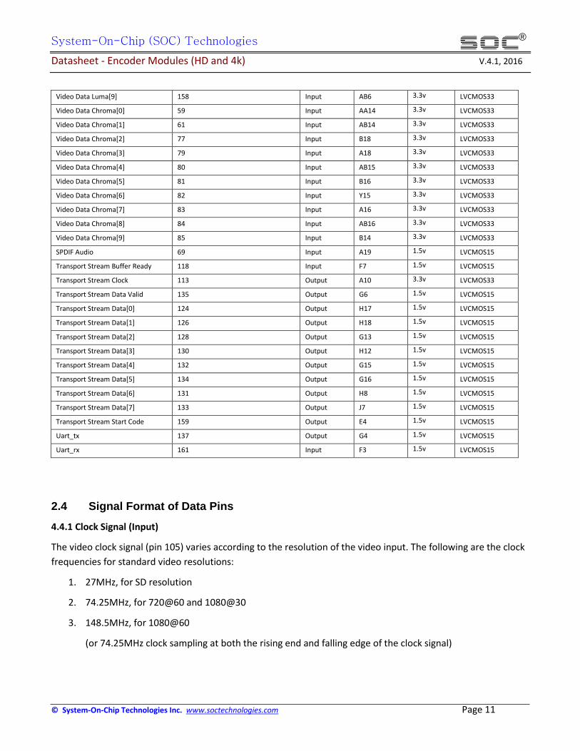
2.4 Signal Format of Data Pins
4.4.1 Clock Signal (Input)
The video clock signal (pin 105) varies according to the resolution of the video input. The following are the clock
frequencies for standard video resolutions:
1. 27MHz, for SD resolution
2. 74.25MHz, for 720@60 and 1080@30
3. 148.5MHz, for 1080@60
(or 74.25MHz clock sampling at both the rising end and falling edge of the clock signal)

System-On-Chip (SOC) Technologies
Datasheet - Encoder Modules (HD and 4k) V.4.1, 2016
© System-On-Chip Technologies Inc. www.soctechnologies.com Page 12
®
4.4.2 Video Data Signals (input)
The input to the encoder module, H.264 or MPEG-2 listed in Table-1, is raw video data in YUV format (4:2:2 or
4:2:0), with 10 input lines, Video Data Luma[0] to Video Data Luma[9], for Luma and 10 input lines, Video Data
Chroma[0] to Video Data Chroma[9], for the Chroma. The precision can be either 8 bits or 10 bits. When 8 bits
precision is used, Video Data Luma[0] , Video Data Luma[1], Video Data Chroma[0], and Video Data Chroma[2]
are zeros.
On top of the video Luma and Chroma data, the Video Horizontal Sync and Video Vertical Sync signals are
required for frame synchronization. A Video Clock (refer to section 4.4.1 for the clock frequencies) is required,
which provides the timing for the parallel input of luma, chroma, as well as the Video Horizontal Sync and
Video Vertical Sync signals.
On top of the above discussed signals, a Video Display Enable control signal (pin #144 ) is used to signify the start
and stop of the input video data.
Input data are sampled at the rising edge of the clock. The clock rates are corresponding to the resolution and
frame rate, as discussed in Section 4.4.1.
4.4.3 Audio Data Signals (input)
Input line SPDIF Audio is for PCM audio input in SPDIF frames. An SPDIF transmitter is required to send the PMC
data to the encoder module. Refer to the SPDIF protocol documents for details.
4.4.4 TS stream Signals (output)
The output of the encoder module is MPEG Transport Stream (TS), which is sent out from the module by 8
parallel lines, Transport Stream Data[0] to Transport Stream Data[7], along with the Transport Stream output
data clock (pin 113). The frequency of the Transport Stream Data clock is 27MHz.
Transport Stream Buffer Ready and Transport Stream Start Code are the signals to inform the user side to take
over the signals.
4.4.5 Encoder Control Signals (Input and output)
Uart_rx and Uart_tx are the API pins for controlling the operations of the encoder. Uart_rx receives the
command from external control device, Uart_tx send the encoder information to the control device. Refer to
the Uart standard for details of Uart operations. The SOC API User Manual provides the register map for the API
control. Refer to the Encoder API User Manual for details.

System-On-Chip (SOC) Technologies
Datasheet - Encoder Modules (HD and 4k) V.4.1, 2016
© System-On-Chip Technologies Inc. www.soctechnologies.com Page 13
®
4.5 Power Rails of MCM-1000A
Table-6 lists the power and ground pins. Refer to Appendix-B for the pin positions of power and ground pins on
the edge connector of the MCM-1000A module.
Table 6: FMC-MCM-1000A Power and Ground Pins
MCM-1000S Connector Pin Voltage
1,3,5,7,9,11,13,15 3.3V
10,12,14,16 1.2V
22,24,26,28,30,32 1.5V
189,191,193,195,197,199 2.5V
188,190,192,194 1.3V
43,45,47,49,51,53,55,57 1.0V
2,4,6,8,18,20,34,36,42,44,62,72 Ground
17,35,37,39,41,71 Ground
73,75,129 Ground
74 Ground
163,165,167,169,175,177,185,187,203 Ground
168,170,172,174,176,184,186,200,202,204 Ground
4.6 Power Requirement
The total power at operation required by a given encoder ranges from 0.5 to 3 watts, depending on the
resolution and frame rate. Overall, it is normally below 3W.
4.7 Power Supply Amperage
All of the power rails, 1.0v, 1.2v, 1.3v, 1.5v, 2.5v, and 3.3v, are required to be supplied via the power pins, as
listed in Table-6. These power rails are also shown in the edge connector schematics in Appendix-B. It has been
tested that 2A (amps) for each power rail is sufficient, although it could be much lower.

System-On-Chip (SOC) Technologies
Datasheet - Encoder Modules (HD and 4k) V.4.1, 2016
© System-On-Chip Technologies Inc. www.soctechnologies.com Page 14
®
5. MCM-1000Z Module
5.1 Block Diagram and Major Components
The MCM-1000Z is a module based on the Xilinx Zynq-7000, XC7Z035 (or XC7Z045) FPGA. The logics of the FPGA
are used for video encoding (or decoding), and the ARM processors in the FPGA are used for audio encoding (or
decoding). The SOC video encoder (or decoder) and the audio encoder (or decoder) IP cores are stored in the
flash memory, to allow the module to function as an encoder (or decoder) on booting. Fig. 8 shows a block
diagram and major components of the MCM-1000Z.
Fig. 8. MCM-1000Z block diagram and major components
5.2 Standard Encoder Modules Based on MCM-1000Z
The MCM-1000Z has two versions – assembled with XC7Z035 and XC7Z045 FPGA. Although it can be configured
for multiple HD encoders (or decoders), The standard encoder modules based on the MCM-1000Z are for 4k
resolutions, with the XC7Z035 version for 4k@30 and XC7Z045 for 4k@60. Audio encoding (or decoding) is
performed by the ARM processors inside the FPGA. Table-7 lists 4 examples of the standard H.264 and H.265 4k
encoder modules. Refer to the Module Selection Guide for more 4k encoder modules offered by SOC based on
the MCM-1000Z. Non-standard modules are also possible according to user requirement, with normally a
minimum order quantity (MOQ).
The MCM-1000Z can also be configured into 4k decoders. The details of the decoder modules are provided in
the Datasheet - Decoder Modules.
Zynq-7000 XC7Z035 Or XC7Z045
DDR3 #1 MT41J128M16JT
DDR3 #2 MT41J128M16JT
MM80-204B1-1 Compatible Connector
Power rails: 1.0v, 1.2v, 1.3v, 1.5v, 2.5v, and 3.3v
S25FL128SAGNFI001

System-On-Chip (SOC) Technologies
Datasheet - Encoder Modules (HD and 4k) V.4.1, 2016
© System-On-Chip Technologies Inc. www.soctechnologies.com Page 15
®
Table-7 Examples of standard encoder modules based on MCM-1000Z
Product # Specifications Standard Profile Resolution Chroma Precision Frame Rate Audio
EC-VA-H264-10b-30-4k-MZ H.264 up to High 4k (3840x2160) 4:2:0/4:2:2 10 bits 30fps AAC or MPEG2 Layer-2 EC-VA-H264-10b-60-4k-MZ H.264 up to High 4k (3840x2160) 4:2:0/4:2:2 10bits 60fps AAC or MPEG2 Layer-2 EC-VA-H265-10b-60-1080-MZ H.265 Main 10 1080 (1920x1080) 4:2:0/4:2:2 10bits 60fps AAC or MPEG2 Layer-2 EC-VA-H265-10b-30-4k-MZ H.265 Main 10 4k (3840x2160) 4:2:0/4:2:2 10bits 30fps AAC or MPEG2 Layer-2
5.3 Pin Assignments and Electrical Properties of MCM-1000Z
Table 8 shows the pin the assignments for the standard encode modules based on the FMC-MCM-1000Z.
The Schematics of MCM-1000Z edge connector are attached in Appendix-C of this document, which shows the
pin numbers for data, clock, and power. The FPGA pin names connected to the edge pins are also displayed in
the schematics, along with voltages of the pins. It is noticed that the encoder modules listed in Table-7 use only
some of the pins that are connected to the FPGA. These assigned pins are listed in Table-8, below.
Table-8 also lists the FPGA pin numbers for the edge pins assigned to the standard encoder modules (listed in
Table-7). Refer to the XC7Z035/045 Datasheet for the FPGA pins. The XC7Z035/045 datasheet provides further
information regarding the use of these pins, if needed (normally not needed).
Table 8: Encoder Module Pin Assignment for MCM-1000Z
Description MCM-1000Z Edge Connector Pin
# Direction FPGA Pin #
Voltage IO Standard
PS Soft Reset_B 156 Input B19 3.3V LVCMOS33
Video Clock 105 Input AG21 3.3v LVCMOS33
Video Horizontal Sync 133 Input W24 1.5v LVCMOS15
Video Vertical Sync 113 Input AF22 3.3v LVCMOS33
Video Display Enable 115 Input AE22 3.3v LVCMOS33
Video Data Luma[0] 135 Input W25 1.5v LVCMOS15
Video Data Luma[1] 137 Input W26 1.5v LVCMOS15
Video Data Luma[2] 116 Input V27 1.5v LVCMOS15
Video Data Luma[3] 118 Input W28 1.5v LVCMOS15
Video Data Luma[4] 124 Input W29 1.5v LVCMOS15
Video Data Luma[5] 126 Input W30 1.5v LVCMOS15
Video Data Luma[6] 128 Input V28 1.5v LVCMOS15
Video Data Luma[7] 130 Input V29 1.5v LVCMOS15
Video Data Luma[8] 132 Input T30 1.5v LVCMOS15
Video Data Luma[9] 134 Input U30 1.5v LVCMOS15

System-On-Chip (SOC) Technologies
Datasheet - Encoder Modules (HD and 4k) V.4.1, 2016
© System-On-Chip Technologies Inc. www.soctechnologies.com Page 16
®
Video Data Luma[10] 117 Input AG22 3.3v LVCMOS33
Video Data Luma[11] 119 Input AH22 3.3v LVCMOS33
Video Data Luma[12] 121 Input AJ21 3.3v LVCMOS33
Video Data Luma[13] 123 Input AK21 3.3v LVCMOS33
Video Data Luma[14] 125 Input AF23 3.3v LVCMOS33
Video Data Luma[15] 127 Input AF24 3.3v LVCMOS33
Video Data Luma[16] 92 Input AJ23 3.3v LVCMOS33
Video Data Luma[17] 94 Input AJ24 3.3v LVCMOS33
Video Data Luma[18] 96 Input AG24 3.3v LVCMOS33
Video Data Luma[19] 98 Input AG25 3.3v LVCMOS33
Video Data Luma[20] 77 Input AJ16 3.3v LVCMOS33
Video Data Luma[21] 79 Input AK16 3.3v LVCMOS33
Video Data Luma[22] 81 Input AH17 3.3v LVCMOS33
Video Data Luma[23] 83 Input AH16 3.3v LVCMOS33
Video Data Luma[24] 85 Input AH18 3.3v LVCMOS33
Video Data Luma[25] 87 Input AJ18 3.3v LVCMOS33
Video Data Luma[26] 80 Input AF13 3.3v LVCMOS33
Video Data Luma[27] 82 Input AG15 3.3v LVCMOS33
Video Data Luma[28] 84 Input AG17 3.3v LVCMOS33
Video Data Luma[29] 86 Input AG16 3.3v LVCMOS33
Video Data Luma[30] 107 Input AH21 3.3v LVCMOS33
Video Data Luma[31] 122 Input AH29 3.3v LVCMOS33
Video Data Luma[32] 144 Input AE28 3.3v LVCMOS33
Video Data Luma[33] 146 Input AF28 3.3v LVCMOS33
Video Data Luma[34] 148 Input AF29 3.3v LVCMOS33
Video Data Luma[35] 150 Input AG29 3.3v LVCMOS33
Video Data Luma[36] 100 Input AH23 3.3v LVCMOS33
Video Data Luma[37] 102 Input AH24 3.3v LVCMOS33
Video Data Luma[38] 104 Input AJ25 3.3v LVCMOS33
Video Data Luma[39] 106 Input AK25 3.3v LVCMOS33
Video Data Chroma[0] 143 Input T29 1.5v LVCMOS15
Video Data Chroma[1] 145 Input U29 1.5v LVCMOS15
Video Data Chroma[2] 147 Input R28 1.5v LVCMOS15
Video Data Chroma[3] 149 Input T28 1.5v LVCMOS15
Video Data Chroma[4] 151 Input P30 1.5v LVCMOS15
Video Data Chroma[5] 153 Input R30 1.5v LVCMOS15
Video Data Chroma[6] 155 Input N29 1.5v LVCMOS15
Video Data Chroma[7] 157 Input P29 1.5v LVCMOS15
Video Data Chroma[8] 159 Input N28 1.5v LVCMOS15
Video Data Chroma[9] 161 Input P28 1.5v LVCMOS15
Video Data Chroma[10] 89 Input AK17 3.3v LVCMOS33

System-On-Chip (SOC) Technologies
Datasheet - Encoder Modules (HD and 4k) V.4.1, 2016
© System-On-Chip Technologies Inc. www.soctechnologies.com Page 17
®
Video Data Chroma[11] 91 Input AK18 3.3v LVCMOS33
Video Data Chroma[12] 93 Input AF19 3.3v LVCMOS33
Video Data Chroma[13] 95 Input AG19 3.3v LVCMOS33
Video Data Chroma[14] 97 Input AH19 3.3v LVCMOS33
Video Data Chroma[15] 99 Input AJ19 3.3v LVCMOS33
Video Data Chroma[16] 101 Input AF20 3.3v LVCMOS33
Video Data Chroma[17] 103 Input AG20 3.3v LVCMOS33
Video Data Chroma[18] 109 Input AJ20 3.3v LVCMOS33
Video Data Chroma[19] 111 Input AK20 3.3v LVCMOS33
Video Data Chroma[20] 38 Input AE12 3.3v LVCMOS33
Video Data Chroma[21] 40 Input AF12 3.3v LVCMOS33
Video Data Chroma[22] 50 Input AG12 3.3v LVCMOS33
Video Data Chroma[23] 52 Input AH12 3.3v LVCMOS33
Video Data Chroma[24] 54 Input AH14 3.3v LVCMOS33
Video Data Chroma[25] 56 Input AH13 3.3v LVCMOS33
Video Data Chroma[26] 58 Input AJ14 3.3v LVCMOS33
Video Data Chroma[27] 60 Input AJ13 3.3v LVCMOS33
Video Data Chroma[28] 59 Input AK13 3.3v LVCMOS33
Video Data Chroma[29] 61 Input AK12 3.3v LVCMOS33
Video Data Chroma[30] 108 Input AJ26 3.3v LVCMOS33
Video Data Chroma[31] 110 Input AK26 3.3v LVCMOS33
Video Data Chroma[32] 112 Input AH26 3.3v LVCMOS33
Video Data Chroma[33] 114 Input AH27 3.3v LVCMOS33
Video Data Chroma[34] 136 Input AK27 3.3v LVCMOS33
Video Data Chroma[35] 138 Input AK28 3.3v LVCMOS33
Video Data Chroma[36] 139 Input AJ28 3.3v LVCMOS33
Video Data Chroma[37] 141 Input AJ29 3.3v LVCMOS33
Video Data Chroma[38] 140 Input AJ30 3.3v LVCMOS33
Video Data Chroma[39] 142 Input AK30 3.3v LVCMOS33
SPDIF Audio 27 Input Y20 1.5v LVCMOS15
Transport Stream Buffer Ready 29 Input AA20 1.5v LVCMOS15
Transport Stream Clock 31 Output AA18 1.5v LVCMOS15
Transport Stream Data Valid 33 Output AA19 1.5v LVCMOS15
Transport Stream Data [0] 152 Output AF30 3.3v LVCMOS33
Transport Stream Data [1] 154 Output AG30 3.3v LVCMOS33
Transport Stream Data [2] 158 Output AE30 3.3v LVCMOS33
Transport Stream Data [3] 160 Output AB29 3.3v LVCMOS33
Transport Stream Data [4] 162 Output AB30 3.3v LVCMOS33
Transport Stream Data [5] 164 Output AA27 3.3v LVCMOS33
Transport Stream Data [6] 166 Output AA28 3.3v LVCMOS33
Transport Stream Data [7] 120 Output AH28 3.3v LVCMOS33

System-On-Chip (SOC) Technologies
Datasheet - Encoder Modules (HD and 4k) V.4.1, 2016
© System-On-Chip Technologies Inc. www.soctechnologies.com Page 18
®
Uart_tx 90 Output AK15 3.3v LVCMOS33
Uart_rx 88 Input AJ15 3.3v LVCMOS33
Video Frame Sync Clock (Decoder only) 80 Input AF15 3.3v LVCMOS33
Video Frame Sync Pause (Decoder only) 131 Input V23 1.5v LVCMOS15
5.4 Signal Format of Data Pins
5.4.1 Clock Signal (Input) and Data Video Data Signals (input)
The video clock signal (pin 105) varies according to the resolution of the video input. Although the MCM-1000Z
modules are mainly used for 4k resolutions, the clock signals for lower resolutions are provided here as well,
which can be useful for multiple channels. The following are the clock frequencies for standard video
resolutions, along with the data pin assignments:
1. 27MHz, for SD resolution
20 out of the 80 data pins are used:
First 10 luma data pins, Video Data Luma[0] - Video Data Luma[9], and
First 10 chroma data pins, Video Data Chroma[0] - Video Data Chroma[9].
For 8bit precision, Video Data Luma[0], Video Data Luma[1], Video Data Chroma[0], and Video Data
Chroma[1] are zeros.
2. 74.25MHz, for 720@60 and 1080@30
20 out of the 80 data pins are used:
First 10 luma data pins, Video Data Luma[0] - Video Data Luma[9], and
First 10 chroma data pins, Video Data Chroma[0] - Video Data Chroma[9].
For 8bit precision, Video Data Luma[0], Video Data Luma[1], Video Data Chroma[0], and Video Data
Chroma[1] are zeros.
3. 148.5MHz, for 1080@60
(or 74.25MHz clock sampling at both the rising end and falling edge of the clock signal)
20 out of the 80 data pins are used:
First 10 luma data pins, Video Data Luma[0] - Video Data Luma[9], and
First 10 chroma data pins, Video Data Chroma[0] - Video Data Chroma[9].
For 8bit precision, Video Data Luma[0], Video Data Luma[1], Video Data Chroma[0], and Video Data
Chroma[1] are zeros.

System-On-Chip (SOC) Technologies
Datasheet - Encoder Modules (HD and 4k) V.4.1, 2016
© System-On-Chip Technologies Inc. www.soctechnologies.com Page 19
®
4. 148.5MHz, for 4k@30
(or 74.25MHz clock sampling at both the rising end and falling edge of the clock signal)
For 4k@30 resolution, the same clock rate of 148.5MHz is used. However, 40 data line (out of the 80
available) are assigned, due to higher data rate.
The first 20 luma data pins, Video Data Luma[0] - Video Data Luma[19], and
The first 20 chroma data pins, Video Data Chroma[0] - Video Data Chroma[19].
For 8bit precision, Video Data Luma[0], Video Data Luma[1], Video Data Luma[10], Video Data
Luma[11], Video Data Chroma[0], Video Data Chroma[1], Data Chroma[10], and Video Data
Chroma[11] are zeros.
5. 148.5MHz, for 4k@60
(or 74.25MHz clock sampling at both the rising end and falling edge of the clock signal)
For 4k@60 resolution, the same clock rate of 148.5MHz is used. However, all of the 80 data lines are
used, due to higher data rate.
40 luma data pins, Video Data Luma[0] - Video Data Luma[39], and
40 chroma data pins, Video Data Chroma[0] - Video Data Chroma[39].
For 8bit precision, the following data pins are zeros:
Video Data Luma[0] = 0,
Video Data Luma[1] = 0,
Video Data Luma[10] = 0,
Video Data Luma[11] = 0,
Video Data Luma[20] = 0,
Video Data Luma[21] = 0,
Video Data Luma[30] = 0,
Video Data Luma[31] = 0,
Video Data Chroms[0] = 0,
Video Data Chroms [1] = 0,
Video Data Chroms [10] = 0,
Video Data Chroms [11] = 0,
Video Data Chroms [20] = 0,
Video Data Chroms [21] = 0,

System-On-Chip (SOC) Technologies
Datasheet - Encoder Modules (HD and 4k) V.4.1, 2016
© System-On-Chip Technologies Inc. www.soctechnologies.com Page 20
®
Video Data Chroms [30] = 0,
Video Data Chroms [31] = 0,
On top of the video Luma and Chroma data, the Video Horizontal Sync and Video Vertical Sync signals are
required for frame synchronization. A Video Clock (refer to section 5.4.1 for the clock frequencies) is required,
which provides the timing for the parallel input of Luma, Chroma, as well as the Video Horizontal Sync and
Video Vertical Sync signals.
On top of the above discussed signals, a Video Display Enable control signal is used to signify the start and stop
of the input video data.
Input data are sampled at both edges of the clock, if 74.25MHz clock is used.
5.4.2 Audio Data Signals (input)
Input line SPDIF Audio is for PCM audio input in SPDIF frames. An SPDIF transmitter is required to send the PMC
data to the encoder module. Refer to the SPDIF protocol documents for details.
5.4.3 TS stream Signals (output)
The output of the encoder module is MPEG Transport Stream (TS), which is sent out from the module by 8
parallel lines, Transport Stream Data[0] to Transport Stream Data[7], along with the Transport Stream output
data clock (pin 31). The frequency of the Transport Stream Data clock is 50MHz.
Transport Stream Buffer Ready is the signal to inform the user side to take over the signals.
5.4.4 Encoder Control Signals (Input and output)
Uart_rx and Uart_tx are the API pins for controlling the operations of the encoder. Uart_rx receives the
command from external control device, Uart_tx send the encoder information to the control device. Refer to
the Uart standard for details of Uart operations.
The SOC API User Manual provides the register map for the API control. Refer to the Encoder API User Manual
for details.
5.4.5 Video Frame Sync (input for Decoder)
Video Frame Sync clock is used in a Decoder module to relock the output frame sync to an external source. Use
of this signal is optional, and must be tied to ‘0’ when not used. Note relocking the frame will cause an
interruption in the video output, and thus should only be used at start-up. Video Frame Sync Pause is used to
pause the frame sync relock.

System-On-Chip (SOC) Technologies
Datasheet - Encoder Modules (HD and 4k) V.4.1, 2016
© System-On-Chip Technologies Inc. www.soctechnologies.com Page 21
®
5.4.6 Software Reset (input)
PS Software Reset is an active low input signal used to reset the FPGA. If not used, do not connect it or tie it to
3.3V power.
5.5 Power Rails of MCM-1000Z
Table 9 lists the power and ground pins. Refer to Appendix-C for the power and ground pins on the edge
connector of the MCM-1000Z module.
Table 9: MCM-1000Z Power and Ground Pins
MCM-1000Z Connector Pin Voltage
1,3,5,7,9,11,13,15 3.3V
10,12,14,16 1.2V
22,24,26,28,30,32 1.5V
189,191,193,195,197,199 2.5V
188,190,192,194 1.3V
43,45,47,49,51,53,55,57 1.0V
2,4,6,8,18,20,34,36,42,44,62,72 Ground
17,35,37,39,41,71 Ground
73,75,129 Ground
74 Ground
175,177,185,187,203 Ground
184,186,200,202,204 Ground
5.6 Power Requirement
The total power at operation required by a given encoder ranges from 1 to 4 watts, depending on the resolution
and frame rate. Overall, it is normally below 4W.
5.7 Power Supply Amperage
All of the power rails, 1.0v, 1.2v, 1.3v, 1.5v, 2.5v, and 3.3v, are required to be supplied via the power pins, as
listed in Table-9. It has been tested that 3A (amps) for each power rail is sufficient, although it could be much
lower.
6. Carrier Board PCB Reference Designs

System-On-Chip (SOC) Technologies
Datasheet - Encoder Modules (HD and 4k) V.4.1, 2016
© System-On-Chip Technologies Inc. www.soctechnologies.com Page 22
®
SOC has several evaluation boards for evaluating the encoder and decoder modules (and for the IP cores as
well). These evaluation boards provide not only the DDR3 SODIMM connectors to connect the encoder (and/or
decoder) modules, but also commonly used digital video/audio ports, such as SDI and HDMI. Ethernet port of
tri-speed, 10/100/1000Mbps, as a network connection, is used in all of the SOC evaluation boards.
6.1 FMC-MCM-1000 Evaluation Board
Fig. 9 shows a photo of the FMC-MCM-1000 board. Major components and I/O ports are marked in the figure.
Refer to the User Guide of FCM-MCM-1000 for further details.
SOC provides the Schematics of FMC-MCM-1000, under NDA, to the customers that have purchased the encoder
(or decoder) Modules. Firmware of the FMC-MCM-1000, including I/O drivers and networks IP core, is also
available for licensing. Please contact SOC sales, [email protected], for details.
Fig. 9. FMC-MCM-1000 evaluation board
6.2 VTR-2000 Evaluation Board

System-On-Chip (SOC) Technologies
Datasheet - Encoder Modules (HD and 4k) V.4.1, 2016
© System-On-Chip Technologies Inc. www.soctechnologies.com Page 23
®
Fig. 10 and Fig. 11 show the top and bottom views of the VTR-2000 board. Major components and I/O ports are
marked in the figure. Refer to the User Guide of VTR-2000 for further details.
SOC provides the Schematics of VTR-2000, under NDA, to the customers that have purchased the encoder (or
decoder) Modules. Firmware of the VTR-2000, including I/O drivers and networks IP core, is also available for
licensing. Please contact SOC sales, [email protected], for details.
Fig. 10. VTR-2000 evaluation board top view
HD SDI #1 HD SDI #2 10/100/1000Mbps Ethernet
HDMI in HDMI Out
Spartan-6 LX45T FPGA
Push Buttons
Power connector 12V (800mA minimum)
Extension Headers
LEDs
JTAG
Connector for WiFi module #1
Connector for WiFi module #2
Mini USB

System-On-Chip (SOC) Technologies
Datasheet - Encoder Modules (HD and 4k) V.4.1, 2016
© System-On-Chip Technologies Inc. www.soctechnologies.com Page 24
®
Fig. 11. VTR-2000 evaluation board bottom view
6.3 VTR-4000 Evaluation Board
Fig. 12 and Fig. 13 show the top and bottom views of the VTR-4000 board. Major components and I/O ports are
marked in the figure. Refer to the User Guide of VTR-4000 for further details.
SOC provides the Schematics of VTR-4000, under NDA, to the customers that have purchased the encoder (or
decoder) modules. Firmware of the VTR-4000, including I/O drivers and networks IP core, is also available for
licensing. Please contact SOC sales, [email protected], for details.
Connector for SOC Codec Module
Connector for SOC Codec Module

System-On-Chip (SOC) Technologies
Datasheet - Encoder Modules (HD and 4k) V.4.1, 2016
© System-On-Chip Technologies Inc. www.soctechnologies.com Page 25
®
Fig. 12. VTR-4000 evaluation board top view
Fig. 13. VTR-4000 evaluation board bottom view
Connector for SOC Codec Module
Connector for SOC Codec Module
HD SDI #1 HD SDI #2 10/100/1000Mbps
Ethernet HDMI in HDMI Out
Spartan-6 LX45T FPGA
Push Buttons
Power connector 12V (800mA minimum)
Extension Headers
LEDs
JTAG
Connector for WiFi module #1
Connector for WiFi module #2
Mini USB
HD SDI #3 HD SDI #4

System-On-Chip (SOC) Technologies
Datasheet - Encoder Modules (HD and 4k) V.4.1, 2016
© System-On-Chip Technologies Inc. www.soctechnologies.com Page 26
®
7. Ordering Information
Fig. 14 shows the product code naming convention for the SOC MPEG codec modules and IP cores. Non-
standard codec modules can be ordered following the same naming format (minimum order quantity is required
for non-standard modules).
Fig. 14 SOC MPEG codec (IP cores and modules) product code naming convention
8. Contact Information
Please Contact SOC head office or distributor for product details or place orders.
Head Office
System-On-Chip (SOC) Technologies Inc.
60 Baffin Place
Waterloo, ON, Canada N2V 1Z7
Telephone: 1-519-880-8609
E-mail: [email protected]
EC-V-H264-10b-60-1080-MA
EC=Encoder DC=Decoder TC=Transcoder
V=Video only
A=Audio only
VA=Video+Audio
H265=H.265/HEVC
H264=H.264/AVC
MPEG2=MPEG2
12b=12bit Precision
10b=10bit Precision
8b=8 bit Precision
MA=Artix Module, MS =Spartan Module, MZ=Zynq Module
IP =IP Core
CS=Chipset
4k = 3840X2160 resolution
1080 = up to1080 (1080X1920 ,Interlaced or progressive)
720 = up to720 (720X1280, Interlaced or progressive)
480= up to 480
(480X640, Interlaced or progressive)
120=120 Frame/Sec. 60=60 Frame/Sec. 30=30 Frame/Sec.
Example Code

System-On-Chip (SOC) Technologies
Datasheet - Encoder Modules (HD and 4k) V.4.1, 2016
© System-On-Chip Technologies Inc. www.soctechnologies.com Page 27
®
9. Document Revisions
Version # Revision Date Notes
V.1.0 2014/02/15 First release
V.1.1 2015/05/10
V.2.0 2016/02/25
V.3.0 2016/05/20
V.3.1 2016/10/30 Added MCM-1000Z
V.4.0 2016/11/01
V.4.1 2016/11/25

System-On-Chip (SOC) Technologies
Datasheet - Encoder Modules (HD and 4k) V.4.1, 2016
© System-On-Chip Technologies Inc. www.soctechnologies.com Page 28
®
Appendix - A MCM-1000S Edge Connector Schematics

System-On-Chip (SOC) Technologies
Datasheet - Encoder Modules (HD and 4k) V.4.1, 2016
© System-On-Chip Technologies Inc. www.soctechnologies.com Page 29
®

System-On-Chip (SOC) Technologies
Datasheet - Encoder Modules (HD and 4k) V.4.1, 2016
© System-On-Chip Technologies Inc. www.soctechnologies.com Page 30
®

System-On-Chip (SOC) Technologies
Datasheet - Encoder Modules (HD and 4k) V.4.1, 2016
© System-On-Chip Technologies Inc. www.soctechnologies.com Page 31
®
Appendix - B MCM-1000A Edge Connector Schematics

System-On-Chip (SOC) Technologies
Datasheet - Encoder Modules (HD and 4k) V.4.1, 2016
© System-On-Chip Technologies Inc. www.soctechnologies.com Page 32
®

System-On-Chip (SOC) Technologies
Datasheet - Encoder Modules (HD and 4k) V.4.1, 2016
© System-On-Chip Technologies Inc. www.soctechnologies.com Page 33
®

System-On-Chip (SOC) Technologies
Datasheet - Encoder Modules (HD and 4k) V.4.1, 2016
© System-On-Chip Technologies Inc. www.soctechnologies.com Page 34
®
Appendix - C MCM-1000Z Edge Connector Schematics

System-On-Chip (SOC) Technologies
Datasheet - Encoder Modules (HD and 4k) V.4.1, 2016
© System-On-Chip Technologies Inc. www.soctechnologies.com Page 35
®

System-On-Chip (SOC) Technologies
Datasheet - Encoder Modules (HD and 4k) V.4.1, 2016
© System-On-Chip Technologies Inc. www.soctechnologies.com Page 36
®


![AK7734 Evaluation Board Rev - AKM Evaluation Board Rev.1 AKD7734-A [AKD7734-A] 2011/07 - 2 - Evaluation Board Diagram Board Diagram +12V-12V](https://img.dokumen.tips/doc/110x75/5c03e45309d3f203258d6861/ak7734-evaluation-board-rev-akm-evaluation-board-rev1-akd7734-a-akd7734-a-201107.jpg)