Embed Size (px)
Citation preview

Procedia Engineering 69 ( 2014 ) 1286 – 1295
Available online at www.sciencedirect.com
1877-7058 © 2014 The Authors. Published by Elsevier Ltd.Selection and peer-review under responsibility of DAAAM International Viennadoi: 10.1016/j.proeng.2014.03.121
ScienceDirect
24th DAAAM International Symposium on Intelligent Manufacturing and Automation, 2013
Dataflow Computing and Its Impact on Automation Applications
Peter Panfilova,*, Sergey Salibekyanb aMinistry of Economic Development, 1st Tverskaya-Yamskaya St. 1,3, Moscow 125993, Russian Federation
bNational Research University – Higher School of Economics, Myasnitskaya St. 20, Moscow 101000, Russian Federation
Abstract
Developing efficient, scalable and reconfigurable supervisory control and data acquisition (SCADA) systems presents a unique set of challenges inherent in the development of distributed computer architectures, algorithms, protocols and procedures for large-scale networked industrial automation applications. A research project on dataflow automation system architecture is presented exploring the research and engineering issues related to the development of computer architecture for the next generation distributed supervision and control systems that exploits and leverages dataflow computation model. Major focus of research is on new object-attribute architecture of dataflow computing environment which is particularly suitable for the design and implementation of reconfigurable scalable heterogeneous distributed applications in industrial automation area. The state-of-the-art in the application of the dataflow model of computation is accompanied with description of software tools developed for programming, simulation, debugging and test of automation applications that follow the object-attribute dataflow model. © 2014 The Authors. Published by Elsevier Ltd. Selection and peer-review under responsibility of DAAAM International Vienna.
Keywords:industrial automation; dataflow; controlflow; parallel processing; multiprocessing; heterogeneous system; distributed controlapplication; object-attribute architecture
1. Introduction
The current state of industrial automation technology is such that the supervision and control of complex plants cannot be achieved without considerable costs in terms of hardware infrastructure and software development. Modern industrial SCADA installations represent heterogeneous parallel and distributed processing platforms that demonstrate complex real-time and asynchronous behavior at large scale. Efficient design of such systems requires
* Corresponding author. Tel.: +43-650-531-3133.
E-mail address: [email protected]
© 2014 The Authors. Published by Elsevier Ltd.Selection and peer-review under responsibility of DAAAM International Vienna
1287 Peter Panfi lov and Sergey Salibekyan / Procedia Engineering 69 ( 2014 ) 1286 – 1295
the use of appropriate models of parallel computations to provide efficient mechanisms for data and program abstraction, computations parallelization and dynamic (re)allocation to available computing resources, such as those provided by the dataflow model of computations.
The dataflow program execution model is an alternative to the control flow execution model exemplified by von Neumann computer architecture. An important advantage of dataflow computation paradigm over the control flow paradigm is that it constitutes a powerful model of parallel computation. There are two major problems associated with von Neumann (stored-program) computer architecture that prevents from efficient multiprocessing and distributed computing application development. These are memory latency and synchronization overhead [1]. The dataflow computer architectures tackle these with inherently powerful model of parallel computation. Unlike controlflow model that uses the program counter as a special point of control of a conventional sequential computer, the dataflow model describes computation in terms of locally controlled "triggering" events each corresponding to the launch of computation in a dedicated functional unit (FU). The dataflow model does not imply a limit on the size or complexity of functional units; it can be represented by a single instruction, or a sequence of instructions. A functional unit operation is triggered when all the input data it requires is available. In a dataflow execution, many FUs may be ready to execute simultaneously (locally controlled by their operand availability), and thus these FUs represent many asynchronous concurrent computation events.
First works on dataflow computer architecture dated back to the early 1970s dealt with the use of dataflow program graphs to represent and exploit the parallelism in programs [2, 3, 4]. In computer architecture, dataflow program graphs were originally applied to computer architecture design as a machine-level program representation, while in concurrency theory dataflow concepts were extensively used for modeling parallel software. Multithreaded architectures, popular nowadays, can be considered as having dataflow roots from this early research. The ability of the dataflow model to tolerate latency, by switching dynamically between ready computation threads, and to support low overhead distributed synchronization in hardware, has made it the candidate of choice for what has later been called "latency tolerant" architectures and applications.
A dataflow computation model [5] influences many areas of computer science and engineering research and development from processor design and high level logic design to signal processing, multithreaded architectures and distributed computing, from programming languages and parallel compilation to programming of systolic and reconfigurable processors.
Deploying dataflow computing in the industrial automation arena presents challenges in three key areas: parallel processing, scalability, and heterogeneous computing. The first of these is the need to efficiently support parallel processing in large-scale networked industrial automation environment. The second is the need to ensure scalability in the face of continuously evolving industrial distributed supervision and control projects. The third is that, increasingly, these solutions are being deployed in environments that are heterogeneous by its nature, and that need to reconfigure to minimize infrastructure costs. This paper reviews the recent developments in the area of reconfigurable heterogeneous distributed computing for automation (supervision and control) application. The first section review the state-of-the-art of the dataflow computing as it is manifested in new object-attribute approach to the dataflow computation model implementation. The second section proposes the object-attribute dataflow model as a programming model for reconfigurable computing in automation application. The third section describes software tools that allows for easy and intuitive programming and debugging of dataflow automation applications.
2. Object-Attribute Dataflow Computing Concept
In this section, we present a new computer architecture that belongs to the dataflow class (that is, computations in a system are data-driven) and that was introduced in early 2000s under the names of attribute or A-architecture and object-attribute or OA architecture [6-8]. Dataflow control in the OA-architecture is provided, firstly, by a new way of machine algorithm description (OA-programming language instructions are used mainly for description of data circulating in a computer system) and, secondly, by different (internal) organization of the functional unit operation to realize computations (arithmetic, logical, etc., operations). A functional unit (FU) in OA-architecture receives information pairs(not instructions) each of which is essentially a collection of data and a tag/attribute describing it. In early OA literature [6] such a tag/attribute was also frequently referred to as a milli-instruction. Hence follows the another name for the proposed architecture –milli-instruction architecture.
1288 Peter Panfi lov and Sergey Salibekyan / Procedia Engineering 69 ( 2014 ) 1286 – 1295
There are several notions in the foundation of the OA-architecture of dataflow computer system. These are as follows.
An information pair (IP) (attributed data) – a set of a computation load (data or references to data) and a tag/attribute (unique identifier) as a description of the load. For example, let us consider an information pair
{TemperatureRoom=19},
where “=” is a sign which shows that the attribute is coupled to the tag.
Milli-command or milli-instruction or milli-operation (mOp) is an IP, where tag refers to the mechanism of data processing by the FU.
A capsule is a set of IPs that describe an object. The capsule can be used for data abstraction. Each IP in capsule corresponds to specific feature of the described object. Capsule is loaded to the RAM of the computing node. For example, a Box object can be represented with a following capsule:
{Object=box, Material=cardboard, HeightInCentimeters=20, WidthInCentimeters=50, DepthInCentimeters=40}.
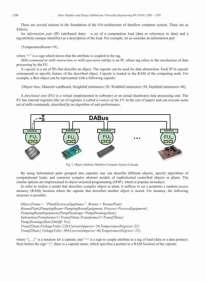
A functional unit (FU) is a virtual (implemented in software) or an actual (hardware) data processing unit. The
FU has internal registers (the set of registers is called a context of the FU in the rest of paper) and can execute some set of milli-commands, described by an algorithm of unit performance.
Fig. 1. Object-Attribute Dataflow Computer System Concept.
By using information pairs grouped into capsules one can describe different objects, specify algorithms of computational loads, and construct complex abstract models of sophisticated controlled objects or plants. The similar options are implemented in object-oriented programming (OOP), which is popular nowadays.
In order to realize a model that describes complex object or plant, it suffices to set a pointerto a random access memory (RAM) location where the capsule that describes another object is stored. For instance, the following structure is possible:
Object{Name = “PlantElectricalAppliance”, Rooms = RoomsPlant} RoomsPlant{PumpingRoom=PumpingRoomEquipment, Process=ProcessEquipment} PumpingRoomEquipment{PumpDrainage=PumpDrainageState} Substation{Transformer1=Transf1State,Transformer2=Transf2State} PumpDrainageState{OnOff=Yes} Transf1State{VoltageVolts=220,CurrentAmperes=50,TemperatureDegrees=25} Transf2State{ VoltageVolts=360,CurrentAmperes=60,TemperatureDegrees=23},
where “{…}” is a notation for a capsule; and “=” is a sign to couple attribute to a tag of load (data or a data pointer). Here before the sign “{“, there is a capsule name, which specifies a pointer to a RAM location of the capsule.
1289 Peter Panfi lov and Sergey Salibekyan / Procedia Engineering 69 ( 2014 ) 1286 – 1295
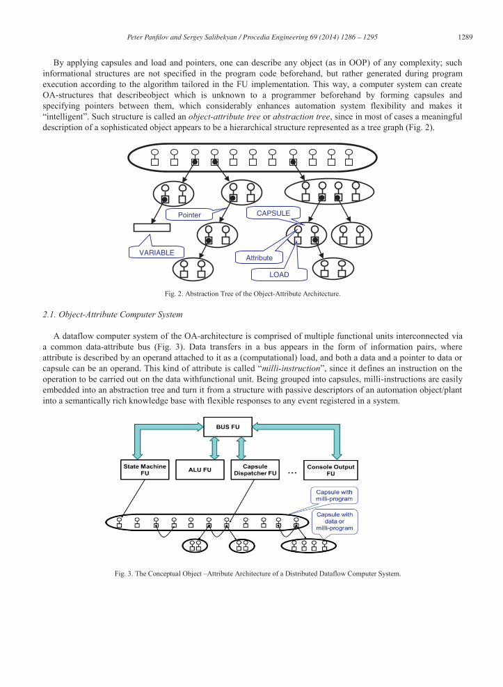
By applying capsules and load and pointers, one can describe any object (as in OOP) of any complexity; such informational structures are not specified in the program code beforehand, but rather generated during program execution according to the algorithm tailored in the FU implementation. This way, a computer system can create OA-structures that describeobject which is unknown to a programmer beforehand by forming capsules and specifying pointers between them, which considerably enhances automation system flexibility and makes it “intelligent”. Such structure is called an object-attribute tree or abstraction tree, since in most of cases a meaningful description of a sophisticated object appears to be a hierarchical structure represented as a tree graph (Fig. 2).
Fig. 2. Abstraction Tree of the Object-Attribute Architecture.
2.1. Object-Attribute Computer System
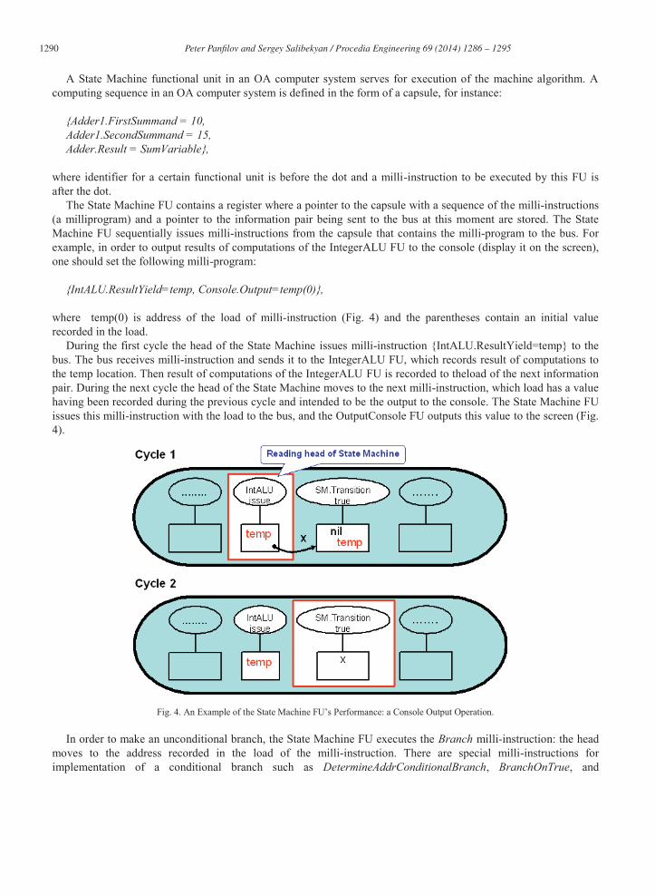
A dataflow computer system of the OA-architecture is comprised of multiple functional units interconnected via a common data-attribute bus (Fig. 3). Data transfers in a bus appears in the form of information pairs, where attribute is described by an operand attached to it as a (computational) load, and both a data and a pointer to data or capsule can be an operand. This kind of attribute is called “milli-instruction”, since it defines an instruction on the operation to be carried out on the data withfunctional unit. Being grouped into capsules, milli-instructions are easily embedded into an abstraction tree and turn it from a structure with passive descriptors of an automation object/plant into a semantically rich knowledge base with flexible responses to any event registered in a system.
Fig. 3. The Conceptual Object –Attribute Architecture of a Distributed Dataflow Computer System.
LOAD
Attribute
CAPSULE
VARIABLE
Pointer
1290 Peter Panfi lov and Sergey Salibekyan / Procedia Engineering 69 ( 2014 ) 1286 – 1295
A State Machine functional unit in an OA computer system serves for execution of the machine algorithm. A computing sequence in an OA computer system is defined in the form of a capsule, for instance:
{Adder1.FirstSummand = 10, Adder1.SecondSummand = 15, Adder.Result = SumVariable},
where identifier for a certain functional unit is before the dot and a milli-instruction to be executed by this FU is after the dot.
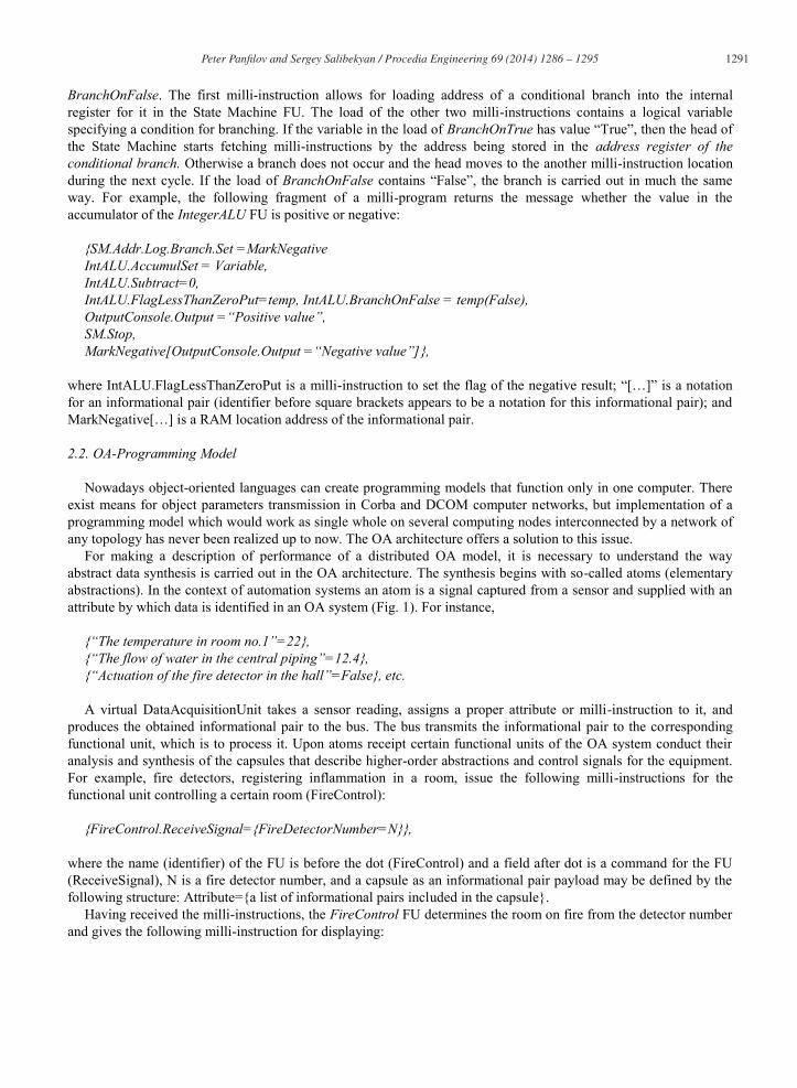
The State Machine FU contains a register where a pointer to the capsule with a sequence of the milli-instructions (a milliprogram) and a pointer to the information pair being sent to the bus at this moment are stored. The State Machine FU sequentially issues milli-instructions from the capsule that contains the milli-program to the bus. For example, in order to output results of computations of the IntegerALU FU to the console (display it on the screen), one should set the following milli-program:
{IntALU.ResultYield=temp, Console.Output=temp(0)},
where temp(0) is address of the load of milli-instruction (Fig. 4) and the parentheses contain an initial value recorded in the load.
During the first cycle the head of the State Machine issues milli-instruction {IntALU.ResultYield=temp} to the bus. The bus receives milli-instruction and sends it to the IntegerALU FU, which records result of computations to the temp location. Then result of computations of the IntegerALU FU is recorded to theload of the next information pair. During the next cycle the head of the State Machine moves to the next milli-instruction, which load has a value having been recorded during the previous cycle and intended to be the output to the console. The State Machine FU issues this milli-instruction with the load to the bus, and the OutputConsole FU outputs this value to the screen (Fig. 4).
Fig. 4. An Example of the State Machine FU’s Performance: a Console Output Operation.
In order to make an unconditional branch, the State Machine FU executes the Branch milli-instruction: the head
moves to the address recorded in the load of the milli-instruction. There are special milli-instructions for implementation of a conditional branch such as DetermineAddrConditionalBranch, BranchOnTrue, and
1291 Peter Panfi lov and Sergey Salibekyan / Procedia Engineering 69 ( 2014 ) 1286 – 1295
BranchOnFalse. The first milli-instruction allows for loading address of a conditional branch into the internal register for it in the State Machine FU. The load of the other two milli-instructions contains a logical variable specifying a condition for branching. If the variable in the load of BranchOnTrue has value “True”, then the head of the State Machine starts fetching milli-instructions by the address being stored in the address register of the conditional branch. Otherwise a branch does not occur and the head moves to the another milli-instruction location during the next cycle. If the load of BranchOnFalse contains “False”, the branch is carried out in much the same way. For example, the following fragment of a milli-program returns the message whether the value in the accumulator of the IntegerALU FU is positive or negative:
{SM.Addr.Log.Branch.Set =MarkNegative IntALU.AccumulSet = Variable, IntALU.Subtract=0, IntALU.FlagLessThanZeroPut=temp, IntALU.BranchOnFalse = temp(False), OutputConsole.Output =“Positive value”, SM.Stop, MarkNegative[OutputConsole.Output =“Negative value”]},
where IntALU.FlagLessThanZeroPut is a milli-instruction to set the flag of the negative result; “[…]” is a notation for an informational pair (identifier before square brackets appears to be a notation for this informational pair); and MarkNegative[…] is a RAM location address of the informational pair.
2.2. OA-Programming Model
Nowadays object-oriented languages can create programming models that function only in one computer. There exist means for object parameters transmission in Corba and DCOM computer networks, but implementation of a programming model which would work as single whole on several computing nodes interconnected by a network of any topology has never been realized up to now. The OA architecture offers a solution to this issue.
For making a description of performance of a distributed OA model, it is necessary to understand the way abstract data synthesis is carried out in the OA architecture. The synthesis begins with so-called atoms (elementary abstractions). In the context of automation systems an atom is a signal captured from a sensor and supplied with an attribute by which data is identified in an OA system (Fig. 1). For instance,
{“The temperature in room no.1”=22}, {“The flow of water in the central piping”=12.4}, {“Actuation of the fire detector in the hall”=False}, etc. A virtual DataAcquisitionUnit takes a sensor reading, assigns a proper attribute or milli-instruction to it, and
produces the obtained informational pair to the bus. The bus transmits the informational pair to the corresponding functional unit, which is to process it. Upon atoms receipt certain functional units of the OA system conduct their analysis and synthesis of the capsules that describe higher-order abstractions and control signals for the equipment. For example, fire detectors, registering inflammation in a room, issue the following milli-instructions for the functional unit controlling a certain room (FireControl):
{FireControl.ReceiveSignal={FireDetectorNumber=N}},
where the name (identifier) of the FU is before the dot (FireControl) and a field after dot is a command for the FU (ReceiveSignal), N is a fire detector number, and a capsule as an informational pair payload may be defined by the following structure: Attribute={a list of informational pairs included in the capsule}.
Having received the milli-instructions, the FireControl FU determines the room on fire from the detector number and gives the following milli-instruction for displaying:
1292 Peter Panfi lov and Sergey Salibekyan / Procedia Engineering 69 ( 2014 ) 1286 – 1295
{Display.Output={RoomNumber=M, Status=“Warning”}}. If the FireControl FU receives a message on actuation of another detector in room M, then it generates the
following abstractions: {Display.Output={RoomNumber=M, Status=“Fire”}, FireExtinguishingSystem={RoomNumber=M, Instruction=Activate}}. Virtual FUs, participating in abstraction synthesis, and capsules, resulted from that synthesis, may be located in
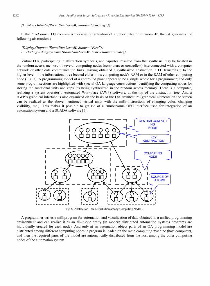
the random access memory of several computing nodes (computers or controllers) interconnected with a computer network or other data communication links. Having obtained a synthesized abstraction, a FU transmits it to the higher level in the informational tree located either in its computing node's RAM or in the RAM of other computing node (Fig. 5). A programming model of a controlled plant appears to be a single whole for a programmer; and only some program sections are highlighted with special OA language constructions identifying the computing nodes for storing the functional units and capsules being synthesized in the random access memory. There is a computer, realizing a system operator’s Automated Workplace (AWP) software, at the top of the abstraction tree. And a AWP’s graphical interface is also organized on the basis of the OA architecture (graphical elements on the screen can be realized as the above mentioned virtual units with the milli-instructions of changing color, changing visibility, etc.). This makes it possible to get rid of a cumbersome OPC interface used for integration of an automation system and a SCADA software [5].
Fig. 5. Abstraction Tree Distribution among Computing Nodes).
A programmer writes a milliprogram for automation and visualization of data obtained in a unified programming
environment and can realize it as an all-in-one entity (in modern distributed automation systems programs are individually created for each node). And only at an automation object parts of an OA programming model are distributed among different computing nodes: a program is loaded on the main computing machine (host computer), and then the required parts of the model are automatically distributed from the host among the other computing nodes of the automation system.
CENTRALCOMPUTING
NODE
COMPUTING NODE
SOURCE OF ATOMS
KEY ABSTRACTION

1293 Peter Panfi lov and Sergey Salibekyan / Procedia Engineering 69 ( 2014 ) 1286 – 1295
3. Object-Attribute Dataflow Automation System Design
Let us consider an automation system’s OA computing environment debugging procedure. A programmer runs a developed software model of an automation object on his/her computer: all the virtual functional units and capsules are created in the random access memory of one computing device. Then, in order to emulate signals which are expected to be coming from the sensors, the programmer specifies milli-instruction or information pair or a set of milli-instructions/information pairs, issues them on the OA computing environment bus, and watches responses from the computing environment to the incoming data. A computing environment response can be traced through the milli-instructions exchanged between the FUs of the OA computing environment (in a real object sensors are the information pair suppliers: they read data and add the corresponding attributes to them). Modeling of behavior of more complicated control objects or plants requires development of milli-instruction sequences, determination of time of informational pair arrival into a system emulator, and creation of special software models emulating equipment behavior (equipment models change the state depending on informational pairs, which describe output signals of an automation system).
For instance, when modeling fire extinguishing system operation, it is possible to specify the milli-instruction with the following attached capsule
{FireControl.ReceiveSignal={FireDetectorNumber=N}}
and produce it to the bus, and then watch a reaction from the system via the console displaying milliinstructions in the bus. If the console has the capsule
{Display.Output={RoomNumber=M, Status=“Warning”}},
it means that the FireControl unit has come into action properly (it has determined a room number with the detector by the detector number and forwarded the “Warning” status message to the output device).
Then it is possible to send the following information structure to the bus: FireControl.ReceiveSignal={FireDetectorNumber=N2}. If the detector is in room M, then the FireControl FU is to produce: {Display.Output={RoomNumber=M, Status=“Fire”}, FireExtinguishingSystem={RoomNumber=M,Instruction=Activate}}. If there is no informational pair expected on the bus, then it means that the program contains a bug. Object-attribute simulation modeling of automation system operation has some advantages ensured by the OA
architecture. They are as follows:
- There is a possibility of the offline simulation (without the need of using real equipment in simulation testbed) and debugging of distributed automation systems.
- There is no need to describe informational structures in advance (as it is the case with data structures and objects in OOP): every structure can be composed “on the fly” in the OA language, which considerably simplifies simulation process.
- There is a possibility of saving test cases in text files without special editing programs. - During simulation there is a possibility of tracking not only external reactions of an automation system (that is,
displaying messages for a system operator and issuing control signals for the equipment) but the internal logic of a program execution if necessary, since a bus shows messages between the functional units implementing a system performance algorithm.
1294 Peter Panfi lov and Sergey Salibekyan / Procedia Engineering 69 ( 2014 ) 1286 – 1295
- Viewing of simulation results is very convenient: in order to extract the needed information from the bus data stream, different filters are utilized; they sort out and display only those informational pairs which meet the desired conditions.
- The process of simulation modeling is clearly arranged: all the signals read from sensors are supplied with an attribute which is displayed as an identifier. This helps to easily find out what parameters are “injected” in the system during simulation and what control signals will be produced by the system to the “outside world”. Similarly, entire information structures to be synthesized during modeling can be easily identified by tags.
- The abstraction tree mechanism makes it possible to carry out development and modeling not only of a whole program but its sections: for instance, a code only for the bottom level of abstractions tree (synthesis from informational atoms) is first created, and then simulation starts and information structures to be produced to a higher level are determined. After that a program for the next abstraction level is developed and simulation of two levels simultaneously is conducted, etc. It is possible to carry out a top-down software development, when the top abstraction level is first written, with a lower abstraction level being simulated by a stub as its information provider.
3.1. Object-Attribute Automation System Architecture Implementation
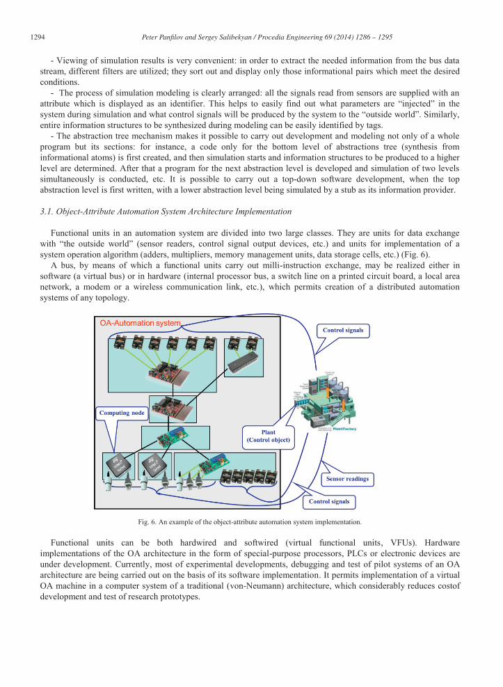
Functional units in an automation system are divided into two large classes. They are units for data exchange with “the outside world” (sensor readers, control signal output devices, etc.) and units for implementation of a system operation algorithm (adders, multipliers, memory management units, data storage cells, etc.) (Fig. 6).
A bus, by means of which a functional units carry out milli-instruction exchange, may be realized either in software (a virtual bus) or in hardware (internal processor bus, a switch line on a printed circuit board, a local area network, a modem or a wireless communication link, etc.), which permits creation of a distributed automation systems of any topology.
Fig. 6. An example of the object-attribute automation system implementation.
Functional units can be both hardwired and softwired (virtual functional units, VFUs). Hardware
implementations of the OA architecture in the form of special-purpose processors, PLCs or electronic devices are under development. Currently, most of experimental developments, debugging and test of pilot systems of an OA architecture are being carried out on the basis of its software implementation. It permits implementation of a virtual OA machine in a computer system of a traditional (von-Neumann) architecture, which considerably reduces costof development and test of research prototypes.
1295 Peter Panfi lov and Sergey Salibekyan / Procedia Engineering 69 ( 2014 ) 1286 – 1295
In order to build unified OA programming environment on all the FUs in a system, a programmer must write the code for realization of virtual FU's logic and the virtual data&attribute bus (DABus) FU code for data exchange between the FUs. During system execution the virtual FUs run on all the computers with the AWP software and on PLCs and carry out computations and data exchange between them. Compatibility of different hardware platforms is achieved due to the fact that logic of virtual FUs is independent on computing node architecture.
Unified OA programming environment is created in the following way: an OA computing environment is launched and interfaces for exchanging data between neighboring nodes are adjusted on each computing node. Then an executable program is loaded on the host computer, and software modules of the OA model are automatically distributed among all the computing nodes of a distributed automation system, and all the system starts up.
An OA automation system can operate with minimum overheads on any hardware platforms like it is with the Java language: in order to transfer an OA program to another platform, a programmer must write the code for this platform to implement operation algorithms for all the types of functional units.
4. Conclusion
As a model of computation, dataflow has a great potential for distributed industrial automation applications. It has been used as a concept for computer architecture, as a model of parallel processing in software, as a highlevel design model for high-performance parallel computer hardware. It has demonstrated its flexibility and efficiency at representing computation in diverse application areas from processor design to development of heterogeneous reconfigurable distributed computing applications.We believe that the dataflow model is not only stillrelevant in many computing research areas, but also that industrial automation area is among application areas that can benefit from this model. Our experiments with OA-architecture of the dataflow computing environment in supervision and control applications demonstrates great potential of dataflow model in this area.
For the future developments of the OA-architecture presented in this paper we plan the realization of a distributed version of the OA-platform and implementation of a PLC-based OA-platform with experimental testing of their capabilities within typical automation systems is anticipated in near future. Object-attribute programming environment improvement is conducted towards creation of an index-based addressing system (it enables extension of address space of the OA environment to several computing nodes), as well as the implementation of mechanism of capsule transfer between computing nodes. Also an implementation of functions for the OA-software upload and for automatic distribution among computing nodes of the automation system is underway now, and an extension of the OA-programming language capabilities is planned. The activities associated with creation of a test bed for debugging and test of the object-attribute dataflow (software and hardware) applications, as well as the development of benchmark automation applications, such as fire alarm systems and systems for automated fire extinguishing, room access control, room climate control, and conveyor product quality control, are planned in near term.
References
[1] Arvind , R.A. Iannucci, A critique of multiprocessing von Neumann style, Proc. of the 10th annual international symposium on Computer architecture, June 13-17, 1983, Stockholm, Sweden, pp. 426-436. [DOI:10.1145/800046.801684]
[2] A. L. Davis, R. M. Keller, Data flow program graphs, IEEE Computer. Vol. 15. No. 2. February, 1982. pp. 26-41. [3] J.B. Dennis, First version of a data-flow procedure language, Proc. of the Colloque sur la Programmation, Paris, France, April 9-11. Lecture
Notes in Computer Science, vol. 19, Springer-Verlag: Berlin, New York, 1974, pp. 362-376. [4] G. Kahn, The semantics of a simple language for parallel processing, J.L. Rosenfeld (Ed.), Information Processing 74, Proc. of the IFIP
Congress 74, North Holland, Amsterdam (1974), pp. 471–475. [5] Data flow computing: theory and practice / edited by John A. Sharp. Ablex Publishing Corp. Norwood, NJ, USA, 1992. [6] S.M. Salibekyan, Principles of milliinstruction architecture as a basis for development of high-performance computer systems, Automation
and Modern Technologies (Avtomatizatsiya i Sovremennye Tekhnologii), No. 5, 2002. (in Russian) [7] S.M. Salibekyan, P.B. Panfilov, Object-attribute architecture is a new approach to object systems design, Information Technologies,
No.2(186)/2012, pp.8-13. (in Russian) [8] S.M. Salibekyan, P.B. Panfilov. Object-attribute architecture for design and modeling of distributed automation systems, Automation and Remote Control, Vol.73, No.3/March 2012, pp.587-595.[DOI: 10.1134/S0005117912030174]