Embed Size (px)
Citation preview
• Snap action electrical contacts minimize chatter, bounce, and wear, and ensure longterm electrical and mechanical reliability
• The fail-safe dual bellows used in KPU 6 and KPU 16 prevent refrigerant loss and enable premature cut-out when a fault occurs
• SPDT or SPST switch a in single control models. SPST or SPDT with high-low pressure signal in dual control models
• Manual trip function (electrical contact function can be tested without the use of tools)
• Easily replaces Johnson Controls and Ranco products
• Wide pressure range: from low pressure KPU 2 with narrow differential to KPU 6 and KPU 16 for high pressure refrigerants (R410A, R744)
• Automatic, manual or convertible reset versions available
• Vibration and shock resistant
UL listed for USA and Canada, E31024
Data sheet
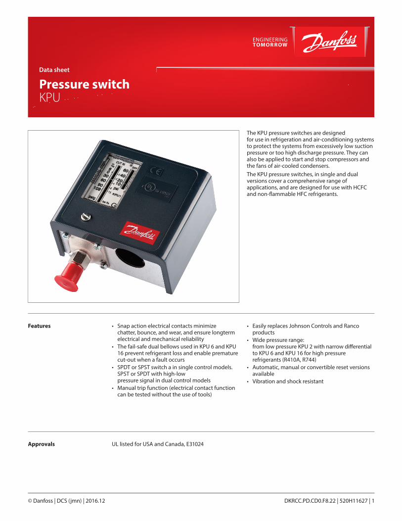
Pressure switch KPU
© Danfoss | DCS (jmn) | 2016.12 DKRCC.PD.CD0.F8.22 | 520H11627 | 1
The KPU pressure switches are designed for use in refrigeration and air-conditioning systems to protect the systems from excessively low suction pressure or too high discharge pressure. They can also be applied to start and stop compressors and the fans of air-cooled condensers. The KPU pressure switches, in single and dual versions cover a comprehensive range of applications, and are designed for use with HCFC and non-flammable HFC refrigerants.
Features
Approvals
© Danfoss | DCS (jmn) | 2016.122 | 520H11627 | DKRCC.PD.CD0.F8.22
Materials in contact with medium Unit type Material
KPU 1, KPU 2, KPU 5, KPU 15
Tin bronze, no. CW452K, EN 1652Nickel plated free cutting steel, no. 1.0737/ 1.0718 to EN 10277
KPU 6, KPU 16 Stainless steel bellows
KPU with capillary tube Copper SF-CU no. 2.0090 to DIN 1787
Ambient temperature -40 – 122 °F (175 °F for max 2 hours)
Maximum working pressure
Low pressure (LP) KPU 1, KPU 2 and LP side of KPU 15, KPU 16: 250 psig
High pressure (HP)
KPU 5 and KPU 15 on HP side: 510 psig
KPU 6 and KPU 16 on HP side: 675 psig
KPU 6 and KPU 16 on HP side: 610 psig for products used according to 97/23/EG PED directive
Maximum testing pressure
Low pressure (LP) KPU 1, KPU 2 and LP side of KPU15, KPU16: 290 psig
High pressure (HP) KPU 5 and KPU 15 on HP side: 530 psig
KPU 6 and 16 on HP side: 725 psig
Cable entry 7/8 in cable entry for ½ in male pipe thread connection (conduit boss)
Contact loadAlternating current
FLA = 24 A @ 120 V AC 24 A @ 240 V AC
LRA = 144 A @ 120 V AC 144 A @ 240 V AC
LRA is rated for make only
Direct current 240 V DC: 12W pilot duty
Wire dimension 10 AWG maximum
Enclosure ~NEMA 1
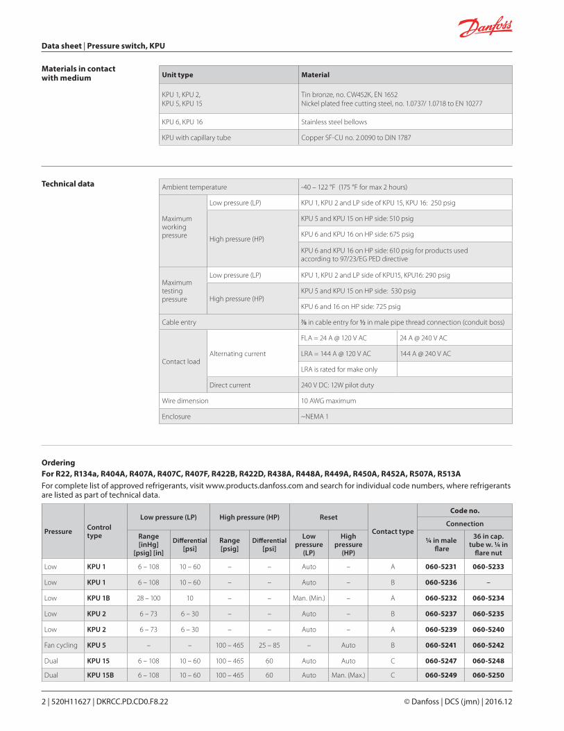
For R22, R134a, R404A, R407A, R407C, R407F, R422B, R422D, R438A, R448A, R449A, R450A, R452A, R507A, R513A For complete list of approved refrigerants, visit www.products.danfoss.com and search for individual code numbers, where refrigerants are listed as part of technical data.
Pressure Control type
Low pressure (LP) High pressure (HP) Reset
Contact type
Code no.
Connection
Range [inHg]
[psig] [in]
Differential[psi]
Range [psig]
Differential[psi]
Low pressure
(LP)
High pressure
(HP)
¼ in male flare
36 in cap. tube w. ¼ in
flare nut
Low KPU 1 6 – 108 10 – 60 – – Auto – A 060-5231 060-5233
Low KPU 1 6 – 108 10 – 60 – – Auto – B 060-5236 –
Low KPU 1B 28 – 100 10 – – Man. (Min.) – A 060-5232 060-5234
Low KPU 2 6 – 73 6 – 30 – – Auto – B 060-5237 060-5235
Low KPU 2 6 – 73 6 – 30 – – Auto – A 060-5239 060-5240
Fan cycling KPU 5 – – 100 – 465 25 – 85 – Auto B 060-5241 060-5242
Dual KPU 15 6 – 108 10 – 60 100 – 465 60 Auto Auto C 060-5247 060-5248
Dual KPU 15B 6 – 108 10 – 60 100 – 465 60 Auto Man. (Max.) C 060-5249 060-5250
Data sheet | Pressure switch, KPU
Technical data
Ordering
FWFW
FWFW
HP
LP
Data sheet | Pressure switch, KPU
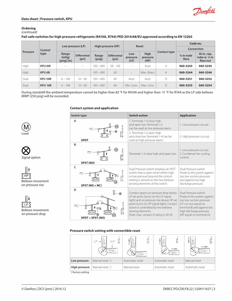
Low pressure Manual reset. 1) Automatic reset Automatic reset Manual reset
High pressure Manual reset. 1) Manual reset Automatic reset Automatic reset1) Factory setting
Pressure switch setting with convertible reset
Ordering (continued)
Pressure Control type
Low pressure (LP) High pressure (HP) Reset
Contact type
Code no.
Connection
Range [inHg]
[psig] [in]
Differential[psi]
Range [psig]
Differential[psi]
Low pressure
(LP)
High pressure
(HP)
¼ in male flare
36 in. cap. tube w. ¼ in
flare nut
High KPU 6W – – 100 – 600 58 – 145 – Auto A 060-5243 060-5245
High KPU 6B – – 100 – 600 60 – Man. (Max.) A 060-5244 060-5246
Dual KPU 16W 6 – 108 10 – 60 100 – 600 60 Auto Auto D 060-5251 060-5252
Dual KPU 16B 6 – 108 10 – 60 100 – 600 60 Min. Conv. Max. Conv. D 060-5253 060-5254
Fail-safe switches for high pressure refrigerants (R410A, R744) PED 2014/68/EU approved according to EN 12263
During standstill the ambient temperature cannot be higher than 82 °F for R410A and higher than -11 °F for R744 as the LP side bellows MWP (250 psig) will be exceeded.
Switch type Switch action Application
A
SPDT
1. Terminals 1-4 close high and open low Terminals 1-2 can be used as low pressure alarm.
1. Low pressure cut-out.
2. Terminals 1-2 open high and close low Terminals 1-4 can be used as high pressure alarm.
2. High pressure cut-out.
B
SPST (NO)
Terminals 1-4 close high and open low .1. Low pressure cut-out.2. Condenser fan cycling control.
C
SPST (NO + NC)
Dual Pressure switch employs an SPST switch that is open when either high or low pressure beyond the control setting is sensed on the two bellows sensing elements of the switch.
Dual Pressure switchProtects the system against too low suction pressure and against too high discharge pressure.
D
SPDT + SPST (NO)
Contact opens on pressure drop below LP set point (turns on the LP signal light) and on pressure rise above HP set point (turns on HP signal light). Contact action is controlled by two bellows sensing elements.Note: max. contact D rating is 50 VA
Dual Pressure switch.Protects the system against too low suction pressure (LP cut-out signal on terminal B) and against too high discharge pressure (HP signal on terminal D).
Contact system and application
Load
Signal option
Bellows movement on pressure rise
Bellows movement on pressure drop
© Danfoss | DCS (jmn) | 2016.12 DKRCC.PD.CD0.F8.22 | 520H11627 | 3
© Danfoss | DCS (jmn) | 2016.124 | 520H11627 | DKRCC.PD.CD0.F8.22
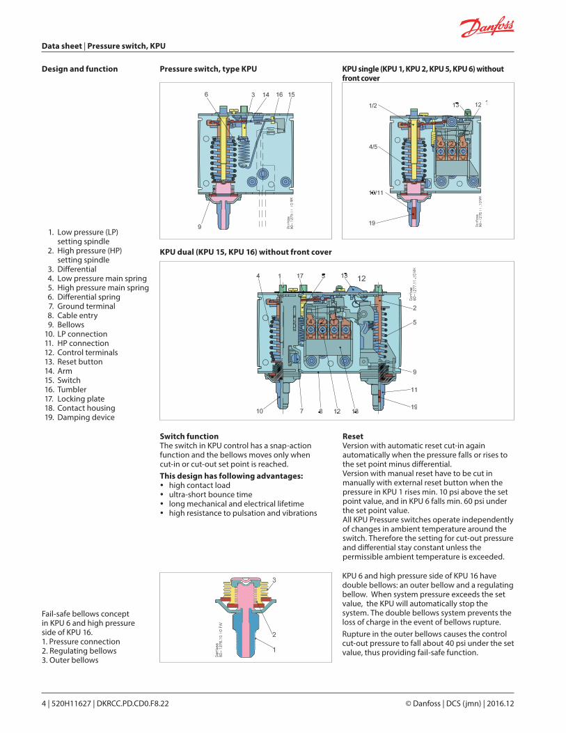
1. Low pressure (LP) setting spindle
2. High pressure (HP) setting spindle
3. Differential 4. Low pressure main spring 5. High pressure main spring 6. Differential spring 7. Ground terminal 8. Cable entry 9. Bellows 10. LP connection 11. HP connection 12. Control terminals 13. Reset button 14. Arm 15. Switch 16. Tumbler 17. Locking plate 18. Contact housing 19. Damping device
Switch functionThe switch in KPU control has a snap-action function and the bellows moves only when cut-in or cut-out set point is reached.This design has following advantages:
y high contact load y ultra-short bounce time y long mechanical and electrical lifetime y high resistance to pulsation and vibrations
ResetVersion with automatic reset cut-in again automatically when the pressure falls or rises to the set point minus differential. Version with manual reset have to be cut in manually with external reset button when the pressure in KPU 1 rises min. 10 psi above the set point value, and in KPU 6 falls min. 60 psi under the set point value. All KPU Pressure switches operate independently of changes in ambient temperature around the switch. Therefore the setting for cut-out pressure and differential stay constant unless the permissible ambient temperature is exceeded.
KPU 6 and high pressure side of KPU 16 have double bellows: an outer bellow and a regulating bellow. When system pressure exceeds the set value, the KPU will automatically stop the system. The double bellows system prevents the loss of charge in the event of bellows rupture.Rupture in the outer bellows causes the control cut-out pressure to fall about 40 psi under the set value, thus providing fail-safe function.
Fail-safe bellows concept in KPU 6 and high pressure side of KPU 16. 1. Pressure connection 2. Regulating bellows 3. Outer bellows
KPU dual (KPU 15, KPU 16) without front cover
Pressure switch, type KPU KPU single (KPU 1, KPU 2, KPU 5, KPU 6) without front cover
Design and function
Data sheet | Pressure switch, KPU
Data sheet | Pressure switch, KPU
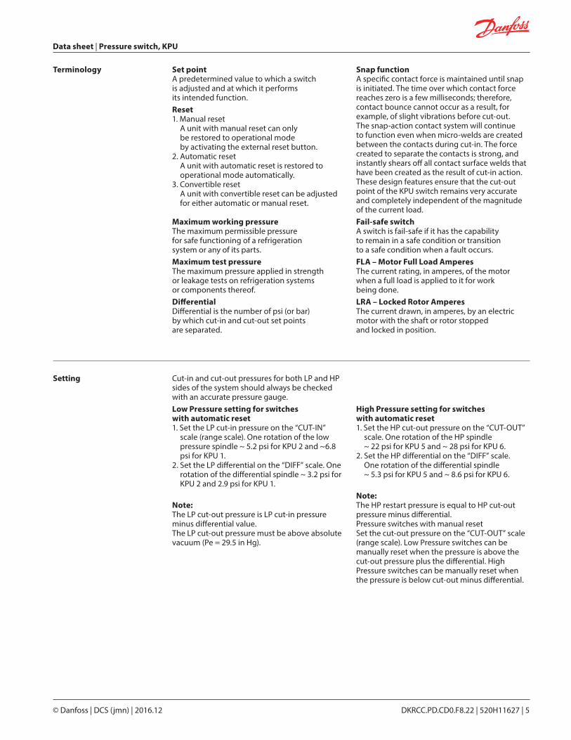
Set point A predetermined value to which a switch is adjusted and at which it performs its intended function.Reset1. Manual reset
A unit with manual reset can only be restored to operational mode by activating the external reset button.
2. Automatic reset A unit with automatic reset is restored to operational mode automatically.
3. Convertible reset A unit with convertible reset can be adjusted for either automatic or manual reset.
Maximum working pressure The maximum permissible pressure for safe functioning of a refrigeration system or any of its parts.Maximum test pressure The maximum pressure applied in strength or leakage tests on refrigeration systems or components thereof.Differential Differential is the number of psi (or bar) by which cut-in and cut-out set points are separated.
Snap function A specific contact force is maintained until snap is initiated. The time over which contact force reaches zero is a few milliseconds; therefore, contact bounce cannot occur as a result, for example, of slight vibrations before cut-out. The snap-action contact system will continue to function even when micro-welds are created between the contacts during cut-in. The force created to separate the contacts is strong, and instantly shears off all contact surface welds that have been created as the result of cut-in action. These design features ensure that the cut-out point of the KPU switch remains very accurate and completely independent of the magnitude of the current load. Fail-safe switch A switch is fail-safe if it has the capability to remain in a safe condition or transition to a safe condition when a fault occurs. FLA – Motor Full Load Amperes The current rating, in amperes, of the motor when a full load is applied to it for work being done.LRA – Locked Rotor Amperes The current drawn, in amperes, by an electric motor with the shaft or rotor stopped and locked in position.
Cut-in and cut-out pressures for both LP and HP sides of the system should always be checked with an accurate pressure gauge.Low Pressure setting for switches with automatic reset1. Set the LP cut-in pressure on the “CUT-IN”
scale (range scale). One rotation of the low pressure spindle ~ 5.2 psi for KPU 2 and ~6.8 psi for KPU 1.
2. Set the LP differential on the “DIFF” scale. One rotation of the differential spindle ~ 3.2 psi for KPU 2 and 2.9 psi for KPU 1.
Note:The LP cut-out pressure is LP cut-in pressure minus differential value. The LP cut-out pressure must be above absolute vacuum (Pe = 29.5 in Hg).
High Pressure setting for switches with automatic reset1. Set the HP cut-out pressure on the “CUT-OUT”
scale. One rotation of the HP spindle ~ 22 psi for KPU 5 and ~ 28 psi for KPU 6.
2. Set the HP differential on the “DIFF” scale. One rotation of the differential spindle ~ 5.3 psi for KPU 5 and ~ 8.6 psi for KPU 6.
Note:The HP restart pressure is equal to HP cut-out pressure minus differential. Pressure switches with manual reset Set the cut-out pressure on the “CUT-OUT” scale (range scale). Low Pressure switches can be manually reset when the pressure is above the cut-out pressure plus the differential. High Pressure switches can be manually reset when the pressure is below cut-out minus differential.
Terminology
© Danfoss | DCS (jmn) | 2016.12 DKRCC.PD.CD0.F8.22 | 520H11627 | 5
Setting
0.47 in.
3.01
in.
1.17
in.
3.52 in. 1.83 in. 1.83 in.5.22 in.
0.47 in.
1.17
in.
3.01
in.
6.75
in.
3.01
in.
3.52 in. 1.83 in.
3.01
in.
6.75
in.
1.83 in.5.22 in.
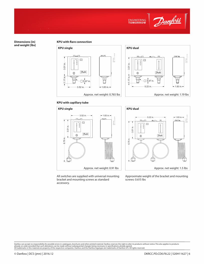
Dimensions [in] and weight [lbs]
KPU with flare connection
KPU with capillary tube
KPU single
KPU single
Approx. net weight: 0.765 lbs
Approx. net weight: 0.91 lbs
Approx. net weight: 1.19 lbs
Approx. net weight: 1.5 lbs
KPU dual
KPU dual
All switches are supplied with universal mounting bracket and mounting screws as standard accessory.
Approximate weight of the bracket and mounting screws: 0.615 lbs
© Danfoss | DCS (jmn) | 2016.12 DKRCC.PD.CD0.F8.22 | 520H11627 | 6


![FW: [Fwd: FW: Beautiful_TIBET]](https://img.dokumen.tips/doc/110x75/54b8dcf94a79592d6a8b4612/fw-fwd-fw-beautifultibet.jpg)