Embed Size (px)
Citation preview

Data Exchange Interfaces
Overview
What's New?
User Tasks
STEP STEP: Import STEP: Export STEP: Trouble Shooting STEP: Best Practices STEP: FAQ STEP: VBScript macros
3D IGES 3D IGES: Import 3D IGES: Export 3D IGES: Trouble Shooting 3D IGES: Best Practices 3D IGES: FAQ 3D IGES: VBScript Macros
2D IGES 2D IGES: Import 2D IGES: Export 2D IGES: Report File 2D IGES: Trouble Shooting 2D IGES: Best Practices 2D IGES: FAQ 2D IGES: VBScript Macros
DXF/DWG DXF/DWG: Import DXF/DWG: Export DXF/DWG: Report File DXF/DWG: Trouble Shooting DXF/DWG: Best Practices DXF/DWG: FAQ DXF/DWG: VBScript Macros
Administration Tasks Administering Standards Setting the Standard Parameters Locking Settings
DXF-IGES-STEP Batch CGM
CGM: Insertion

CGM: Export STL VRML TDG
Customizing
DXF IGES IGES 2D STEP
Glossary
Index

OverviewWelcome to the Data Exchange Interfaces User's Guide! This guide is intended for users who need to become quickly familiar with the product.
This overview provides the following information:
● Data Exchange Interface in a Nutshell
● Before Reading this Guide
● Getting the Most Out of this Guide
● Accessing Sample Documents
● Conventions Used in this Guide
Data Exchange Interfaces in a NutshellV5 is an open system, capable of interoperating with data in all of the mostly used data format standards in the CAD/CAM/CAE Industry.
For Importing and Exporting external files there are miscellaneous formats : STEP, IGES, DXF/DWG, CGM, STL, VRML, and STRIM/STYLER.
These formats are used to transfer geometric data (surfaces and wireframe) between different CAD-CAM systems in following situations :
● concurrent engineering with using several CAD-CAM systems
● migration of databases when changing system (example: for new V5 customers)
● exchanges of geometric data with clients or suppliers
Data Exchange Interfaces are :
● STEP AP203 / AP214 format (Standard for the Exchange of Product model data) : the V5 - STEP AP203 Interface and theV5 - STEP AP214 Interface : allow to interactively read and write data in STEP AP203 / AP214 data formats. Its supports geometry and assembly structures and handles topology (shells, solids) on export and import.For instance, you can read a STEP file, edit its content in V5 workbenches, and save the results directly as a STEP file.
● IGES format is supported by the V5 - IGES Interface (IG1) product. V5 - IGES Interface (IG1) helps users working in a heterogeneous CAD/CAM environment to exchange data through a neutral format. The Initial Graphic Exchange Specification (IGES) format, is the most used neutral format to transfer data between heterogeneous CAD systems. Users can perform bi-directional data exchange between dissimilar systems with direct and automated access to IGES files.IGES files containing 3D geometry are imported into CATPart documents. Their type should be "igs".IGES files containing 2D geometry and annotations are imported as CATDrawing documents. Their type should be "ig2".
● DXF/DWG : DXF formats are supported by the V5 - Generative Drafting Products. After creating drawings,

the designers can export data in DXF/DWG formatted files and import the 2D geometric data contained in a DXF/DWG file into a CATDrawing document.
● CGM format is supported by the V5 - Object Manager Products.
● STL format is supported by the V5 - Object Manager Products. STL concerns stereolithography document (.stl).
● STRIM/STYLER : V5 - STRIM/STYLER To CATIA Interface 2 (STC) allows to process in CATIA V5 the Geometry from Strim and Styler Applications. It provides a unique direct Interface from Strim and Styler to CATIA, which operates on Strim and Styler Native Format Files in V5 Environment. The product features a direct access to Styler or Strim data files to convert and store them into V5 format. The product enables to retrieve an existing Styler or Strim design into V5, and proceed to further transformations in Mechanical Solutions, Potentially NC Manufacturing Solutions and Shape Design & Styling solutions.STRIM and STYLER files (with extension ".tdg") can be selected in File Open to Create and Display a part document enclosing the geometry of the files in a V5 Format. Files can be selected in the CATIA - DIGITAL MOCK-UP NAVIGATOR to be inserted as existing components in a Product.
The Data Exchange Interfaces User's Guide has been designed to show you how to Import and Export external files in/from Version 5.
Before Reading this GuidePrior to reading the Data Exchange Interfaces User's Guide, you are recommended to have a look at the Infrastructure User's Guide for information on the generic capabilities common to all products.
Getting the Most Out of this GuideFor each interface, you will learn:
● how to import data,
● or to export data to one of these formats,
● and how entities are dealt with.
then you will find chapters dealing with:
● Trouble Shooting: this chapter provides solutions to repair eventual problems
● Best Practices: this chapter provides information and tips to use interfaces at their best
● FAQ: this chapter lists answers to frequently asked questions
● VBScript Macros: this chapter provides the operating mode for VBScript Macros
DXF-IGES-STEP Batch deals with the Batch processing of files
Accessing Sample Documents

To perform the scenarios, sample documents are provided all along this documentation. For more information about this, refer to Accessing Sample Documents in the Infrastructure User's Guide.

What's New?
Enhanced Functionalities
IGES ●
Strong improvements have been made in order to handle very large assemblies at import and export.The Product Identification for Receiver (Global Section, Field #12) will be used as the Part Number in the Product Properties at import.Overridden faces colors are exported.
IGES 2DIGES 2D interface is now available on UNIX platforms.
IGES 2D - ExportGraphic export for special dimension cases.
DXF-DWG - Export
Enhanced export for dimensions.STEP
Strong improvements have been made in order to handle very large assemblies at import and at export.The Assembly physical structure can be specified at import.Import of CURVE_BOUNDED_SURFACES is now supported.AP 203 with extensions is available at export.
Customizing Settings
DXF/DWG - ImportDrafting standards can be selected and are taken into account at once.Mappings options are replaced by DXF standard.
IGES 2D - ImportDrafting standards can be selected and are taken into account at once.
IGESThe Import Mode options translate an IGES file into one CATPart or into a CATProduct (for 308/408 entities). It replaces the option Join surfaces of each group.The Import Group option activates or de-activates the creation of Selection Sets.
STEP - General SectionThe option Groups (Selection Sets) activates/de-activates the processing of groups that are mapped with Selection Sets.
STEP - Export
AP 203 with extensions has been added to the list of application protocols.

User Tasks
Click on a format:
STEP3D IGES2D IGES
DXF/DWGCGMSTLTDG

STEP Interface
STEP: ImportSTEP: Export
STEP: Trouble ShootingSTEP: Best Practices
STEP: FAQSTEP: VBScript macros

Importing a STEP AP203 / AP214 File
This task shows you how to import to a CATPart or CATProduct document the data contained in a STEP AP203 / AP214 file.
It is also possible to insert a STEP file as an existing component in a CATProduct.
Regarding AP214, both STEP AP 214 IS and STEP AP 214 DIS files are read.
The table entitled What about the elements you import ? provides information on the entities you can import.
You can find further information in the Advanced Tasks:
● Trouble Shooting,
● Best Practices,
● FAQ,
● VBScript Macros.
and in the Customizing STEP Settings chapter.
Statistics about each import operation can be found in the report file and the error file.
1. Click the Open icon or select the File->Open
command.
The File Selection dialog box is displayed.
1. Insert/Existing component command.
The File Selection dialog box is displayed.
2. Set the .stp or .step extension in the Files of type field.
This displays all .stp or .step files contained in the selected directory :

3. Select the .stp or .step file of your choice (MoldedPart.stp, in our example) and click Open.

A progress bar is displayed.
You can use the Cancel button to interrupt the transfer at any time.What is then displayed depends on the contents of the STEP file.
For the File/Open command:
● If the STEP file contains a normalized assembly structure, a CATProduct document is created.
● If the STEP file does not contain any geometrical and topological data, the components will be visible only in the Specification Tree.
● If the STEP file contains also geometrical and topological data, all the components will be present in the Geometry Space and in the Specification Tree.
● If the STEP file contains only geometrical and topological data, a CATPart document is created.
The geometrical elements of the faces, which could not be transferred, are created in the NO SHOW space. In the NO SHOW space, you can visualize the Surface supports and the 3D Curves).
For the Insert/Existing component command:
● if the STEP file contains no assembly information, it is converted to a CATPart,
● if the STEP file contains assembly information, it is converted to a CATProduct referencing several CATPart documents.
The resulting document is inserted in the current CATProduct document, and the graphic window is updated (specification tree and geometry).
● The reference to the STEP file is lost, so any update of the STEP file will have no effect in the CATProduct.
● For both commands, the reference planes are hidden.
● A Geometrical Set is always created. It may be empty:❍ it will contain the valid surfaces imported, if any.
❍ it is empty if there is no valid surfaces, e.g. when the element imported is a solid, or when all surfaces are invalid.
❍ invalid surfaces are sent to a specific Geometrical Set (FaceKO#xxx)
Several STEP options can be customized: ● Continuity optimization of curves and surfaces, to optimize curves and surfaces.
● Geometric Validation Properties, to check the quality of the transfer.
● Groups (Selection Sets), to activate/de-activate the transfer of groups mapped with Selection Sets.
● Detailed report, to set the level of details of the transfer log.
Report file

After the recovery of STEP files, the system generates:
● a report file (name_of_step_file.rpt) where you can find references about the quality of the transfer
● and an error file (name_of_step_file.err) .
These files are created in a location referenced by the CATReport variable. Its default value is
● Profiles\user\Local Settings\Application Data\Dassault Systemes\CATReport on NT (user being you logon id)
● and $HOME/CATReport on UNIX.
Always check the report and error files after a conversion ! Some problems may have occurred without been visually highlighted.
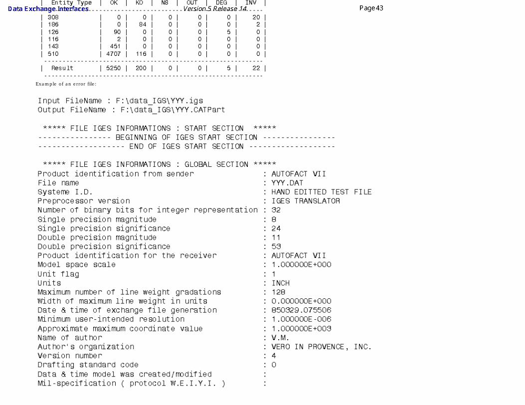
Example of a report file
(Some lines have been replaced with ...)
Legend

OK = TransferredKO = Not TransferredNS = Unsupported
OUT = Out Of SizeDEG = DegeneratedINV = Invalid
● "OUT" entities are OUT of model size. Most of the time, these entities are curves and they are out of the V5 model space. These entities are not created.
● "INV" entities are Invalid entities, that is to say their description within the STEP file is invalid (STEP syntax rules are not respected,...). These entities are not created.
● "DEG" entities are degenerated entities. They are solids (MANIFOLD_SOLID_BREP) or Shells (OPEN_SHELL), or Curves (LINE, CIRCLE,...). Degenerated solids are incomplete solids (at least one Face misses)
Example of error file:
E:\Report\pm6-hc-214.err
Input FileName : G:\Equipe_STEP\STEP\PDES-Prostep\Tr8\Prod\pm6-hc-214.stpOutput FileName :
============================================*** = Processing new independent element* = Intermediate processing!! = Independent element K.O.! = Intermediate error--------------------------------------------<I> = Information<W> = Warning<E> = Error--------------------------------------------[0000] = Message identifier : 0000[T=xxx] = Entity Type Step : xxx[#0000] = Entity identifier number : 0000============================================Actual display level : Customer
Report messages
Here are some of the messages that may appear:● Too many cuts on face boundary. Tip : Use topological reduction option (in IGES) or curve optimization (in IGES or STEP) - see User's Guide
These options are accessible via Tools/Options/Compatibility/STEP dialog boxes, in the Continuity optimization of curves and surfaces section. Select the Advanced optimization option and push the Parameters... button. For more information, click on the link on STEP above.
When the Continuity optimization of curves and surfaces/Advanced optimization option in Tools/Options/Compatibility/STEP is active, the following warning messages may appear in the report file:
● The BSpine Surface is not C1: Approximation of the surface is impossible!This is just a warning, the surface is imported but is not approximated.
● The deformation found of the surface approximation (which is calculated by isoparameters) is : xx millimeters.This indicates that the real deformation found is higher than the Deformation value you have entered in the Parameters box and that the approximation could not be performed. When this occurs for several entities, you will find the following information message at the end of the report file:
● For a better approximation of BSpline surfaces, you can use a "Curves and surfaces approximation" Deformation value of at least : xx millimetersYou can enter this value in the Parameters box of the Continuity optimization of curves and surfaces/Advanced optimization option in Tools/Options/Compatibility/STEP.
What About The Elements You Import ?
Exchanging 3D Geometry
One of the current primary uses of the AP214 Standard is to exchange geometry. The STEP Interface enables users to exchange the B-REP of exact solids. The exchange process is based on AP214. This application protocol is very similar to AP203 as it shares the same resources expressed in the PART 42.
● Conformance Classes 2,3,4 and 6 are supported in AP203.
● Conformance Classes 1 and 2 are supported in AP214 (assembly and 3D geometry / topology management).

Exchanging Visual Presentation of 3D Geometry
Another use of the AP214 Standard is to exchange visual presentation information. The STEP interface enables users to exchange visual presentation of exchanged geometric elements.
Please remember:
● Units:
As the unit system used in Version 5 is MKSA (radians, mm) data from all STEP files will be converted into such units.
● Layers:
● A layer is created in your application for each layer present in the STEP file.
● All entities included in a layer in the STEP file are included in the corresponding layer.
● A layer over 999 is replaced by layer 0.
● Color: ❍ Color exchange is supported.
❍ STEP AP214: When an entity OVERRIDING_STYLE_ITEM exists in the STEP file for a given face, this color overriding is taken into account: the color of the face is overridden.
● Lines: ❍ The line type is taken into account.
❍ If the requested line thickness is defined in your environment, this thickness is taken into account, else the nearest predefined thickness is taken.
● Points: ❍ Point styles are mapped as follows:
STEP point style V5 point style
cross, triangle
plus
circle
square
asterisk
dot
Assemblies
STEP files containing assembly structures can be imported. STEP assemblies are mapped with the Product Structure. Geometry can be defined:
● in STEP in the same file,
● or in STEP in external files (AP 214 external references mechanism). The files referenced are STEP files. External references are supported with STEP AP214, but they are not with STEP AP203.
● or in CATIA in external files. The files referenced are CATIA files. External references are supported with STEP AP214, but they are not with STEP AP203.
● or by links to CATPart, model or cgr files via Product_definition_with associated_document entities. Assemblies generated by V4 CATASM and referencing to .model files or cgr files are supported.

● The physical structure of an imported assembly can be defined by one or several CATProducts (one for each node) depending of the option selected (See the Assemblies physical structure option about the import STEP files containing sub-assemblies).
● CATPart files are linked to the CATProducts as instances of Parts.
● Model files or cgr files are linked as Shapes.
● In the case of referenced files, those files must be in the same location than the root STEP file, or be accessible via the search order.
The attributes of products are taken into account as follows:STEP V5 PRODUCT.ID Part NumberPRODUCT.NAME DefinitionPRODUCT.DESCRIPTION Description PRODUCT_DEFINITION_FORMATION.ID Revision
The attributes of instances of products are taken into account as follows:
STEP V5NEXT_ASSEMBLY_USAGE_OCCURRENCE.ID Component/Instance name

NEXT_ASSEMBLY_USAGE_OCCURRENCE.DESCRIPTION Component/Description
Groups● For each APPLIED_GROUP_ASSIGNMENT pointing to a group and a list of entities in the STEP file, a Selection Set is created. This Selection Set is named with
the name of the pointed GROUP entity and includes all pointed entities.
● The transfer of groups can be activated/de-activated via the Groups (Selection Sets) option.
STEP Part 42 Entities Imported into V5R6 and Higher
Implemented Not yet implemented N/A: Not applicable according to the standard
Shape Representation geometrically bounded wireframe
geometrically bounded surface
edge-based wireframe
shell-based wireframe manifold surface faceted brep advanced brep
High Level Entities geometric_curve_set geometric_set edge_based_wireframe_model
shell_based_wireframe_model
shell_based_surface_model
faceted_brepbrep_with_voids
manifold_solid_brepbrep_with_voids
Entity
Pointcartesian_point
point_on_curve N/A N/A N/A N/A
point_on_surface N/A N/A N/A N/A N/A
point_replica N/A N/A
degenerate_pcurve N/A N/A N/A N/A N/A
Curveline N/A
circle N/A
ellipse N/A
hyperbola N/A
parabola N/A
polyline N/A
b_spline_curve (+ rational)b_spline_curve_with_knots N/A
uniform_curve (+rational) N/A
quasi_uniform_curve (+rational) N/A

bezier_curve N/A
trimmed_curve N/A N/A N/A N/A N/A
composite_curve N/A N/A N/A N/A N/A
composite_curve_on_surface N/A N/A N/A N/A N/A N/A
boundary_curveouter_boundary_curve N/A N/A N/A N/A N/A N/A
pcurve N/A N/A N/A N/A
surface_curve N/A N/A N/A N/A
offset_curve_3d N/A N/A
curve_replica N/A N/A
Surface plane N/A N/A N/A
cylindrical_surface N/A N/A N/A N/A
conical_surface N/A N/A N/A N/A
spherical_surface N/A N/A N/A N/A
toroidal_surface N/A N/A N/A N/A
degenerate_toroidal_surface N/A N/A N/A N/A
surface_of_linear_extrusion N/A N/A N/A N/A
surface_of_revolution N/A N/A N/A N/A
b_spline_surfaceb_spline_surface_with_knots N/A N/A N/A N/A
uniform_surface N/A N/A N/A N/A
quasi_uniform_surface N/A N/A N/A N/A
bezier_surface N/A N/A N/A N/A
rectangular_trimmed_surface N/A N/A N/A N/A N/A N/A
curve_bounded_surface N/A N/A N/A N/A N/A N/A

rectangular_composite_surface N/A N/A N/A N/A N/A N/A
offset_surface N/A N/A N/A N/A N/A
surface_replica N/A N/A N/A N/A N/A
Topologyvertex_point N/A N/A N/A
edge_curve N/A N/A N/A
oriented_edge N/A N/A N/A N/A
vertex_loop N/A N/A N/A N/A
poly_loop N/A N/A N/A N/A N/A
edge_loop N/A N/A N/A N/A
face_boundface_outer_bound N/A N/A N/A N/A
face_surface N/A N/A N/A N/A N/A
advanced_face N/A N/A N/A N/A
oriented_face N/A N/A N/A N/A N/A N/A
vertex_shell N/A N/A N/A N/A N/A N/A
wire_shell N/A N/A N/A N/A N/A N/A
connected_edge_set N/A N/A N/A N/A N/A N/A
open_shell N/A N/A N/A N/A N/A N/A
oriented_open_shell N/A N/A N/A N/A N/A N/A N/A
closed_shell N/A N/A N/A N/A
oriented_closed_shell N/A N/A N/A N/A N/A
manifold_solid_brep N/A N/A N/A N/A N/A N/A
brep_with_voids N/A N/A N/A N/A N/A N/A

Exporting CATPart or CATProduct Data to a STEP AP203 / AP214 File
This task shows you how to save in STEP AP203 / AP214 formats the data contained in a CATPart or CATProduct document. STEP AP203 and STEP AP214 formats are used for the data exchange between the Assembly workbench and other CADCAM software products. Saving your assembly in STEP AP203 / AP214 format comes down to gathering assembly data into one file. The assembly structure and the geometry (in compliance with the STEP format) are saved. If you do not have any STEP license, you can nevertheless save the assembly structure in STEP.You can export:
● CATProduct documents (resulting in STEP AP203 / AP214 files in compliance with Part 44)
● CATShape documents. However, if you re-import a STEP file made from a CATShape, you will create a CATPart.
Regarding AP 214, data are exported to STEP AP 214 IS filesYou can find further information in the Advanced Tasks:
● Trouble Shooting,
● Best Practices,
● FAQ,
● VBScript Macros.
● and in the Customizing STEP Settings chapter.
Statistics about each import operation can be found in the report file and the error file created.
The table entitled What about the elements you export ? provides information on the entities you can export.
1. Open the CATPart or CATProduct document to be saved in STEP AP203 / AP214 format.
2. When the document is open, select the File -> Save As... command.
The Save As dialog box is displayed:

3. Specify the name you want to give to the STEP file in the File name: field.
4. Set the .stp extension in the Save as type field.
You will remember that the extension used in V4 was .step. In Version 5, CATPart and CATProduct documents are exported to files with the extension "stp".
5. Click the Save button to confirm the operation.
A progress bar is displayed.
You can use the Cancel button to interrupt the transfer at any time. If you now open the .stp file you will see that the file header contains the following information:
● the file name
● the date of creation (with the year expressed in four digits meaning that your STEP data will be year 2000-compliant)
● the V5 version used for the conversion.
Choose the Application Protocol in Tools -> Options -> Compatibility, click the STEP tab. Select AP203, AP203+ext or AP214, and click on OK.
Several export options can be customized:
● Detailed report (not yet completely available for export)
● Geometric Validation Properties
● Groups (Selection Sets)
● Application Protocol (AP), to choose the AP203 or the AP214 Application Protocol,
● Assemblies, to use external references, thus reducing memory problems,
● Units, to choose the unit of the exported file,
● Show/NoShow, to export all entities or only visible entities.

Report FileAfter exporting data to STEP files, the system generates:
● a report file (name_of_step_file.rpt) where you can find references about the quality of the transfer
● and an error file (name_of_step_file.err) .
These files are created in a location referenced by the CATReport variable. Its default value is
● Profiles\user\Local Settings\Application Data\Dassault Systemes\CATReport on NT
● and $HOME/CATReport on UNIX.
You can find statistics about the quality of the transfer in those files.
Example of report file:
Example of error file:
C:\WINNT\Profiles\vmu\Local Settings\Application Data\DassaultSystemes\CATReport\03_ClosedTopology.err
Input FileName : E:\users\WebInterfaces\ItfEnglish\itfug.doc\src\samples\03_ClosedTopology.CATPartOutput FileName : E:\users\WebInterfaces\ItfEnglish\itfug.doc\src\samples\03_ClosedTopology.stp
============================================*** = Processing new independent element* = Intermediate processing!! = Independent element K.O.! = Intermediate error--------------------------------------------<I> = Information<W> = Warning<E> = Error--------------------------------------------[0000] = Message identifier : 0000

[T=xxx] = Entity Type Step : xxx[#0000] = Entity identifier number : 0000============================================Actual display level : Customer
What About The Elements You export ?
Exchanging 3D Geometry
One of the current primary uses of the AP214 Standard is to exchange geometry. The STEP Interface enables users to exchange the B-REP of exact solids. The exchange process is based on AP214. This application protocol is very similar to AP203 as it shares the same resources expressed in the PART 42.
Please remember:
● You can export the bodies (volumes, shells and faces) of CATPart or CATShape documents (resulting in STEP AP203 / AP214 files in compliance with Part 42).
● The export of Shells occurs with no limitation and all the structure information can be recovered.
● When a CATProduct document is exported the geometry/topology of the CATPart or CATShape or .model documents is also stored in the .stp file.
Exchanging Visual Presentation of 3D Geometry
Another use of the AP214 or AP203 with extensions Standard is to exchange visual presentation information. The STEP interface enables users to exchange visual presentation of exchanged geometric elements.
Please remember:
● Layers: ❍ Layers on exported entities are supported.
❍ The visibility of layers is not taken into account: all layers are handled in the same way, event if filters are defined.
● Color: ❍ The colors of your model are exported.
❍ STEP AP214: When the color of a given face is different from the color of its solid, an entity OVER_RIDING_STYLE_ITEM is created in the STEP file, and the face keeps the overriding color.
❍ STEP limitation with assemblies: since attributes can not be set on instances of components, the color of instances are not taken into account.
● Lines: ❍ V5 handles 7 types of line whereas STEP proposes 5 types only. The mapping is the following:
V5 line type STEP line type
Continuous
Dotted
Dashed
Chain
Chain double dash
Dotted
Chain
● Thickness is supported at export.
● Points: ❍ Point styles are mapped as follows:
STEP point style V5 point style
cross, triangle
plus
circle

square
asterisk
dot
Miscellaneous
Please remember:
● Units:
The units used are V5 units i.e. MKSA (radians, mm). The angles are exported in radians and lengths in mm or Inch.
● Wires:
If a feature contains several wires (result of a section), the wires will be exported as Composite Curves and will all have the same name (that of the feature).
● Show/NoShow:
By default, hidden objects (i.e. that belong to the No Show space) are not exported. See option Show/NoShow.
● Selection set (AP 214 only!):
For each selection set,an entity APPLIED_GROUP_ASSIGNMENT is created. This entity points to a GROUP entity and to a list of exported geometric entities. The attribute NAME of the entity GROUP is defined by the name of the selection set.
The transfer of groups can be activated/de-activated via the Groups (Selection Sets) option.
When a Body is contained in a Selection Set:● a GROUP entity is created in the STEP file for that Selection Set,
● all the entities of the Body exported in STEP are put into that GROUP.
When an exported entity is contained in a Selection Set:
● a GROUP entity is created in the STEP file for that Selection Set,
● the entity is put into that GROUP.
Assemblies
Support of External References to STEP or CATIA files on Export: the External References functionality is available only with AP214. For more information about the Customizing export mode, refer to Customizing STEP Settings
● Multiple Instances of a Part in an Assembly is possible: a link with the same reference is established in order to limit the number of instances.
● STEP limitation with assemblies: since attributes can not be set on instances of components, the color of instances are not taken into account.
You can save the structure of an assembly with links to CATParts files via PRODUCT_DEFINITION_WITH_ASSOCIATED_DOCUMENT entities.
.model files referenced by a CATProduct are exported in STEP with the following settings:
● Application Protocol AP203 + Structure and Geometry in one file
● Application Protocol AP214 + Structure and Geometry in one file
● Application Protocol AP214 + STEP external references.

The attributes of products
are taken into account as follows:
V5 STEPPart Number PRODUCT.IDDefinition PRODUCT.NAMEDescription PRODUCT.DESCRIPTIONRevision PRODUCT_DEFINITION_FORMATION.ID
The attributes of instances of products are taken into account as follows:
V5 STEPComponent/Instance name NEXT_ASSEMBLY_USAGE_OCCURRENCE.IDComponent/Description NEXT_ASSEMBLY_USAGE_OCCURRENCE.DESCRIPTION
STEP Part 42 Entities Exported from V5R6 and Higher
Implemented Not yet implemented Not generated by V5
N/A: Not applicable according to the standard

Wire (GSM, Free Style, etc.) Not generated by V5
OpenShell (GSM, Shape Design, Free Style, etc.)
Not generated by V5 Geometrical set
Shape
Representationgeometrically
bounded wireframe
geometrically bounded surface
edge-based wireframe
shell-based wireframe
manifold surface faceted brep advanced brep
High Level
Entities geometric_curve_set geometric_set edge_based_wireframe_model
shell_based_wireframe_model
shell_based_surface_model
faceted_brepbrep_with_voids
manifold_solid_brepbrep_with_voids
Entity
Point cartesian_point
point_on_curve N/A N/A N/A
point_on_surface N/A N/A N/A N/A N/A
point_replica N/A N/A N/A N/A
degenerate_pcurve N/A N/A N/A N/A N/A
Curve line thru edge_curve N/A
circle thru edge_curve N/A
ellipse thru edge_curve N/A
hyperbola thru edge_curve N/A
parabola thru edge_curve N/A
polyline N/A
b_spline_curve(+ rational)
b_spline_curve_with_knots
thru edge_curve N/A
uniform_curve (+rational) N/A
quasi_uniform_curve (+rational) N/A
bezier_curve N/A
trimmed_curve N/A N/A N/A N/A N/A
composite_curve N/A N/A N/A N/A N/A
composite_curve_on_surface N/A N/A N/A N/A N/A
boundary_curve
outer_boundary_curve N/A N/A N/A N/A N/A
pcurve N/A N/A N/A
surface_curve N/A N/A N/A N/A
offset_curve_3d N/A N/A
curve_replica N/A N/A
Surface plane N/A N/A N/A
cylindrical_surface N/A N/A N/A
conical_surface N/A N/A N/A N/A

spherical_surface N/A N/A N/A N/A
toroidal_surface N/A N/A N/A N/A
degenerate_toroidal_surface N/A N/A N/A N/A
surface_of_linear_extrusion N/A N/A N/A N/A
surface_of_revolution N/A N/A N/A N/A
b_spline_surface
b_spline_surface_with_knotsN/A N/A N/A N/A
uniform_surface N/A N/A N/A N/A
quasi_uniform_surface N/A N/A N/A N/A
bezier_surface N/A N/A N/A N/A
rectangular_trimmed_surface N/A N/A N/A N/A N/A N/A
curve_bounded_surface N/A N/A N/A N/A N/A N/A
rectangular_composite_surface N/A N/A N/A N/A N/A N/A
offset_surface N/A N/A N/A N/A N/A
surface_replica N/A N/A N/A N/A N/A
Topology vertex_point N/A N/A thru edge_curve N/A
edge_curve N/A N/A thru
oriented_edge N/A
oriented_edge N/A N/A N/A thru edge_loop N/A
vertex_loop N/A N/A N/A N/A
poly_loop N/A N/A N/A N/A N/A
edge_loop N/A N/A N/A thru wire_shell N/A
face_bound
face_outer_boundN/A N/A N/A N/A
face_surface N/A N/A N/A N/A N/A
advanced_face N/A N/A N/A N/A
oriented_face N/A N/A N/A N/A N/A N/A
vertex_shell N/A N/A N/A N/A N/A N/A
wire_shell N/A N/A N/A N/A N/A N/A
connected_edge_set N/A N/A N/A N/A N/A N/A
open_shell N/A N/A N/A N/A N/A N/A
oriented_open_shell N/A N/A N/A N/A N/A N/A N/A
closed_shell N/A N/A N/A N/A
oriented_closed_shell N/A N/A N/A N/A N/A

STEP: Trouble Shooting
ImportIf you need to recover from transfer failures after importing the data contained in a STEP file into a CATPart document, please refer to the IGES: Trouble Shooting chapter because the repairing scenario is the same with IGES files.
There are however some specificities for STEP data, they are detailed just below:
What you need to know
STEP files may describe assemblies that contain CATParts. The result of the conversion is a Product which contains several components.
=> If needed, each part can be analyzed and corrected individually.

If the components have links between them (for example instantiations), the links are recreated in the product.
=> Corrections on the source part are automatically reported to instances.
You are now ready to create the topology. For more information: ● please refer to the next chapter entitled STEP: Best Practices - How to create a topology
● or use the application Healing Assistant for more complex cases.
STEP files with syntax errors
When a STEP file is syntactically invalid, there are error messages in the .err file describing those invalidities.
Syntax errors are responsible for partial loss of STEP file data: all invalid entities and all entities pointing directly or not to invalid entities are ignored. In order to recover all the STEP entities, correct the STEP file before reading it in V5.
Export
None.

STEP: Best Practices
Import
Large AssembliesWe recommend that you import large assemblies in batch mode:
● In this mode the CATPart documents are unloaded once transferred.
● A maximum of the available memory is spared for the translation.
Quality of conversionAlways check the report and error files after a conversion ! Some problems may have occurred without been visually highlighted.
We recommend also that you use the Geometric Validation Properties when they exist. When an error occurs in the comparison, you can locate the problem as follows :
● An error at solid or shell level means that the geometric translation failed.
● An error at product level means that a sub-assembly translation failed.
● An error at instance level means that a component is misplaced.
Note that the error at the lowest level gives the relevant information. It is the first error that appears in the report file:
● An error at solid or shell level involves an error for corresponding product.
● An error at product level involves an error for every product including instances of it.
How to Create a TopologySTEP files usually describe solids. It means that they contain the topology of the model. During the conversion of a part:
● If no problem, the geometry and the topology are imported and the result is a solid.
● If there is a geometric problem, one or several faces of the solid cannot be recreated and the solid itself is degenerated. The resulting model contains:
● an empty PartBody,
● an Geometrical set with a surface corresponding to all faces OK,
● an Geometrical set for each face KO.

=> The repairing methodology is the same as faces KO in IGES.
● There may also be a topological problem, when all the geometry has been converted OK but the topology could not be created. Then the resulting model contains:
● an empty PartBody,
● an Geometrical set with the surfaces that could not be joined properly.
=>The repairing methodology is the same as in IGES: Best Practices - How to create a topology.

Export
Large AssembliesTo export a large V5 Assembly in STEP, we recommend that you open it with the Work with the cache system option active (Tools/Options/Infrastructure/Product Structure/Cache Management/Work with the cache system): When this option is active, the referenced CATPart documents are loaded only during their transfer.
External referencesFor the exchange of large assemblies, we recommend that you use external references, using several small files instead of one large file (this will reduce memory problems).
See the settings for more information.

STEP: FAQ
Import
● Question: You successfully opened the STEP file, there is no KO faces, but the solid was not created.
● Answer: Try an interactive Join on the Shell
● Question: You successfully opened the STEP file, but the parts are not correctly placed.
● Answer: Edit the STEP file with a text editor and look for MAPPED_ITEM entities. Those are old entities not used anymore and not supported. Ask the provider of the STEP file to use CONTEXT_DEPENDENT_SHAPE_REPRESENTATION entities instead.
● Question: You successfully opened the STEP file, there is no KO faces, but there are some missing geometries.
● Answer: Check in the .rpt for NS (Non supported) elements, and consult STEP documentation to have a comprehensive list of Supported Entities
● Question : You receive a 'Low memory state' warning message and your STEP file is not totally converted.
● Answer : There is not enough memory to convert the file completely and all the remaining entities are skipped. We recommend that you use Windows NT4SP06 (and above) for large STEP files and with at least 1 GB of RAM and 2 GB of SWAP.
Export● Question: The .rpt reported that there were one or many KO Faces.
● Answer: The problem might be due to two sources : a bad CATPart or a bug in the STEP code. To verify the CATPart is OK, use the usual tools : Cleaner, NCGM Workbench and make sure there is no major errors. A internal check is done while exporting and a line is added to the .err to warn if the Body is invalid
● Question : I am losing some parts of my assembly while exporting my CATProduct to STEP, why ?

● Answer : Make sure that you do not have any foreign parts included in your CATProduct like STL files or Parasolid files...etc. Those files do not contain any V5 information

except the visualization information and therefore it is impossible to export them as STEP file. If you have CATIA V4 .models in your CATProduct, make sure to have them
migrated to V5 before exporting to STEP.

STEP: VBScript Macros
You can automate Data exchanges between CATIA V5 and STEP using VBScript macros, either at import or export.
Import
1. Create a RunTime window (window in which all runtime variables a set)
2. Type the command:
cnext -macro MyMacro.CATScriptwhere MyMacro.CATScriptis the VBScript macro you want to execute.
● The input files must be writable (not read only). Otherwise the system will display an information box and wait for an acknowledge.
● The output file must not exist in the output directory otherwise the system will ask for a confirmation to overwrite the file and wait for an acknowledge.
You can transfer several files within the same VBScript macro, but it is recommended to do only one transfer per VBScript macro.
Example:
VBScript macro for implementing a STEP AP203 file
Language="VBSCRIPT"
Sub CATMain()
Dim Document0 As Document
' Reading a STEP file
Set Document0 = CATIA.Documents.Open( "E:\tmp\Box.stp)
' Saving the corresponding CATPart
CATIA.ActiveDocument.SaveAs "E:\tmp\Box"
CATIA.Quit
End Sub

Export
1. Create a RunTime window (window in which all runtime variables are set):
2. Type the command:cnext - macro MyMacro.CATScript
where MyMacro. CATScript is the VBScript macro you want to execute.
● The input files must be writable (not read only). Otherwise the system will display an information box and wait for an acknowledge.
● The output file must not exist in the output directory otherwise the system will ask for a confirmation to overwrite the file and wait for an acknowledge.
Examples
VBScript macro for exporting a file to STEP AP203
Language="VBSCRIPT" Sub CATMain() Dim PartDocument0 As Document ' Reading a CATPart file Set PartDocument0 = CATIA.Documents.Open( "E:\tmp\Box.CATPart" ) ' Saving the part in a STEP file PartDocument0.ExportData "E:\tmp\Box2", "stp" CATIA.Quit End Sub
VBScript macro for exporting a Product file to STEP AP203
Language="VBSCRIPT Sub CATMain() Dim ProductDocument0 As Document Set ProductDocument0 = CATIA.Documents.Open( "E:\tmp\Product1.CATProduct" ) ProductDocument0.ExportData "E:\tmp\Product1", "stp" CATIA.Quit End Sub

3D IGES Interface
3D IGES: Import3D IGES: Export
3D IGES: Trouble Shooting3D IGES: Best Practices
3D IGES: FAQ3D IGES: VBScript Macros

Importing a 3D IGES File into a CATPart
This task shows you how to import into a CATPart document the data contained in an IGES file.
Once imported, the data can be handled just as if it were created as a CATPart. The main purpose of such an import is to be able to create shells from IGES faces but you may also find it useful for re-using face contours in the Sketcher application, deforming NURBs in Generative Shape Design or using faces in other V5 applications.
The table entitled What about the elements you import ? provides information on the entities you can import.
You can find further information in the Advanced Tasks:
● Trouble Shooting,
● Best Practices,
● FAQ,
● VBScript Macros.
and in the Customizing 3D IGES Settings chapter.
Statistics about each import operation can be found in the report file created.
The function "Insert / Existing Component" for IGES files is provided by the MULTICAx IGES plug-in and requires a MultiCad license.
1. Select the File->Open command.
The File Selection dialog box is displayed.
2. If the directory contains many different types of files you may wish to set the .igs extension in the Files of type field. This displays all files with the extension "igs" contained in the
selected directory.
In Version 5, both files with the extension "igs" and IGS can be imported to a CATPart document.

3. Select the .igs file of your choice and click Open.


A progress bar is displayed.
You can use the Cancel button to interrupt the transfer at any time.
This creates a new document similar to a CATPart document in all respects and containing all surfaces and 3D wireframe geometry. The data is now available in your session.
● Some invalid geometries may be detected.
● The reference planes are hidden at import.
Several 3D IGES import options can be customized: ● Display of the Completion Dialog Box
● Import mode to import large files containing 308/408 entities.
● Join, to join surfaces in the model you import.
● Continuity optimization of curves and curfaces to optimize curves and surfaces.
● Detection of invalidity in input geometry.
● Representation for boundaries of faces.
● Import Groups to activate or de-activate the creation of Selection Sets.
Report File
After the recovery of 3D IGES files, V5 generates:
● a report file (name_of_file.rpt) where you can find references about the quality of the transfer
● and an error file (name_of_file.err) .
These files are created in a location referenced by
● the USERPROFILE variable on NT. Its default value is Profiles\user\Local Settings\Application Data\Dassault Systemes\CATReport on NT (user
being you logon id)
● the HOME variable on UNIX. Its default value is $HOME/CATReport on UNIX.
Always check the report and error files after a conversion ! Some problems may have occurred without been visually highlighted.

Example of a report file:
Example of an error file:


Report messages
Here are some of the messages that may appear:● Too many cuts on face boundary. Tip : Use topological reduction option (in IGES) or curve optimization (in IGES or STEP) - see User's Guide
These options are accessible via the Tools/Options/Compatibility/IGES or Tools/Options/Compatibility/STEP dialog boxes, in the Continuity optimization of curves and surfaces section. Select the Advanced optimization option and push the Parameters... button. For more information, click on the link on IGES above.
When the Continuity optimization of curves and surfaces/Advanced optimization option in Tools/Options/Compatibility/IGES is active, the following warning messages may appear in the report file:
● The BSpine Surface is not C1: Approximation of the surface is impossible!This is just a warning, the surface is imported but is not approximated.
● The deformation found of the surface approximation (which is calculated by isoparameters) is : xx millimeters.This indicates that the real deformation found is higher than the Deformation value you have entered in the Parameters box and that the approximation could not be performed. When this occurs for several entities, you will find the following information message at the end of the report file:
● For a better approximation of BSpline surfaces, you can use a "Curves and surfaces approximation" Deformation value of at least : xx millimetersYou can enter this value in the Parameters box of the Continuity optimization of curves and surfaces/Advanced optimization option in Tools/Options/Compatibility/IGES.
Invalidity in Input Geometry When invalidities are detected in the input geometry, all the invalid faces (and all the elements of their geometry) are put in a specific Geometrical set named invalid Input Geometry. These
faces are shown as invalid in the report file.
For each invalidity detected, a specific label points to the face concerned. These labels are put in an Annotation Set.xx.
● Deleting an invalid element does not automatically delete the corresponding Annotation Set.
● Only one feature Annotation Set is created at the root of the specification tree, with all the invalidity descriptions.
● Annotation Sets are not exported to IGES, but they can be saved in the CATPart.
What about the Elements You Import?

The following points should be remembered: ● The IGES standards 5.2 and 5.3 are supported. The latter is year 2000-compliant.
● Trimmed and bounded surfaces are transformed into faces.
● Solids and volumes are imported as joined shells as well as text, annotations and 2D geometry are not converted.
● The tolerance used is the default tolerance defined in the Part Design session.
● Properties such as the original colors, the show status, names (if they exist) are maintained in your session.
Processing of names: ● If an IGES entity has a pointer to a "Property Name Entity", the value of this property will be assigned to the name of the V5 entity.
● If the IGES entity has no pointer to a "Property Name Entity" and if its "Directory Entry" field #18 is not blank the V5 name will be computed by appending field #18 and #19 of the "Directory Entry".
● If the entity has neither a "Property Pointer" nor a non-blank field #18 an automatic name will be generated.
● Product Identification for Receiver (Global Section, Field #12) will be used as the Part Number in the Product Properties.
Processing of Group Associativity:
The Group Associativity, in the IGES Norm, is mapped with the type 402 (ASSOCIATIVITY INSTANCE ENTITY).
There are four form numbers which specify group associativities :
Form Meaning
1 Unordered group with back pointers
7 Unordered group without back pointers
14 Ordered group with back pointers
15 Ordered group without back pointers
For each Group Associativity pointing to a list of entities in the IGES file, a selection set is created. This selection set is named with the name of the pointed GROUP entity and includes all pointed entities.
● This applies to known Group Associativity forms (Type 402 - forms 1, 7, 14 and 15) only.
● A Selection set pointing to another Selection set cannot be created.
● When a group is pointed by a second group, the entities of the first group will be pointed by a first Selection set (mapping the first group) and by a second Selection set mapping the second group (including others entities of the second group).
● Only logically dependant IGES entities (Status Number 3-4 = "02" in D.E. section) can be mapped in a Selection set.
● The Import Group option activates or de-activates the creation of Selection Sets.
Processing of 308/408 IGES entities
● If the Map the 308/408 IGES entities onto a Product Structure is not selected, elements contained in dittos are imported as simple elements (dittos are exploded).
● If the Map the 308/408 IGES entities onto a Product Structure is selected, it creates a Product Structure.
● In addition, when selected, it deactivates the mapping of groups to Selection Sets.

To make sure the elements you need to handle in your session are those you expected, here is a list presenting the IGES data supported when imported into a CATPart document:
IGES Element V5 Element Notes
null 0
circular arc 100 circle
composite curve 102 curve, line, circle
conic arc - ellipse 104 form 1 curve
copious data 106 forms 1-3,15 point, curve
unbounded plane 108 form 0 planeFrom V5R12, even independent planes 108 form 0 are imported.
Independent planes 108 form 0 will be displayed as a small square in CATIA
bounded plane 108 form 1 plane
line 110 form 0 line
semi-bounded line 110 form 1 line
unbounded line 110 form 2 line
parametric spline curve 112 curve
parametric spline surface 114 surface
point 116 point
ruled surface 118 surface
surface of revolution 120 surface
tabulated cylinder 122 surface
direction entity 123 direction
transformation matrix 124 matrix
rational B-spline curve 126 curve
rational B-spline surface 128 surface Rational B-spline surfaces are also recognized as planes or cylinder according to their geometrical properties..
offset curve 130 curve, line, circle
offset surface 140 surface
boundary (of skin) 141
either included in the translation of a bounded surface, or curve, line, circle if the transfer of the bounded surface has failed
If the surface is not of type BSpline and C2 continuous, only the Geometry type curves "Curve on a parametric surface" and "Boundary" are taken into account for face creation. 2D Parametric type curves are ignored.

curve on parametric surface 142
either included in the translation of a trimmed surface, or curve, line, circle if the transfer of the trimmed surface has failed
If the surface is not of type BSpline and C2 continuous, only the Geometry type curves "Curve on a parametric surface" and "Boundary" are taken into account for face creation. 2D Parametric type curves are ignored.
bounded surface (of skin) 143 surface
trimmed (parametric) surface 144 surface
manifold solid B-rep(consisting of shell
faceloop
edge listvertex list)
186 form 0(514 form 1510 form 1508 form 1504 form 1502 form 1)
joined shellCreation of a geometrical set or PartBody per shell.
Creation of a PartBody if the shell is closed.
plane surface entity 190 form 0-1 All the surfaces are faces support surfaces : they must be used with entities of type 143, 144 and 510.
Those surfaces are infinite (not limited).
If a face, supported by one of those surfaces, cannot be correctly imported, the "invalidFace" created by CATIA V5 and containing surfaces and curves could present visualization problems on infinite surfaces graphic representation.
right circular cylindrical surface entity 192 form 0-1
right circular conical surface entity 194 form 0-1
toroidal surface entity 198 form 0-1
subfigure definition (detail) 308 see singular subfigure instance
color definition 314 color
associativity instance (group) 402 forms 1,7,14,15 selection set See the Group Associativity
singular subfigure instance (ditto) 408 simple elements or CATParts
See the processing of 308/408 IGES entities.

Exporting CATPart or CATProduct Data to a 3D IGES File
This task shows you how to save in IGES format the data contained in a CATPart, CATProduct or a CATShape document.
However, if you re-import an IGES file made from a CATShape, you will create a CATPart.
IGES 5.3 (year 2000-compliant) is the standard supported.
The table entitled What about the Elements You Export ? provides information on the entities you can export.
You can find further information in the Advanced Tasks: ● Trouble Shooting,
● Best Practices,
● FAQ,
● VBScript Macros.
and in the Customizing 3D IGES Settings chapter.
Statistics about each export operation can be found in the report file created.
1. Open the CATPart or CATProduct document to be saved in IGES format.
2. Select the File -> Save As... command.
The Save As dialog box is displayed.
3. Specify the name of the document in the File name: field.
4. Set the .igs extension in the Save as type field.
● In Version 5, documents can be exported to files with the extension "igs".
● The name of the CATProduct is exported as the Product identification for Receiver.

● The name of the author and of the organization can be exported to the Global Section of the IGES file.
5. Click the Save button to confirm the operation.
A progress bar is displayed.
You can use the Cancel button to interrupt the transfer at any time.
● Several 3D IGES export options can be customized:
● Save only shown entities
● Curve and surface type
● Representation mode
● Name of author and Organization
● Export unit as
● Display of the Completion Dialog Box
Report File

After the exporting data to 3D IGES files, V5 generates:
● a report file (name_of_file.rpt) where you can find references about the quality of the transfer
● and an error file (name_of_file.err) .
These files are created in a location referenced by
● the USERPROFILE variable on NT. Its default value is Profiles\user\Local Settings\Application Data\Dassault Systemes\CATReport on NT (user being you logon id)
● the HOME variable on UNIX. Its default value is $HOME/CATReport on UNIX.
What About the Elements You Export?
● If the representation mode is "Surface", the topology of solids and shells is lost during the export. As a consequence, you have a group of surfaces called an Geometrical set. If you make an Import with Join, you can get a Close Body.
● When a CATProduct is exported, the component .igs and .model files are not stored in the .igs file.Each component of a CATProduct document is translated by a subfigure definition / singular subfigure instance in the .igs file.
● You can choose the export unit.
● The name of the elements to export must be in ASCII format.
● Overridden faces colors are supported.
● You export the final construction object, i.e. the whole specification tree and its history up to the feature at the bottom of the specification tree and not the current feature: for example, you wish to export the specification tree up to Pocket.1 only
In this case, although Pocket.1 is the current feature, you will export all elements of
the specification tree including Copy of Pad.1.If you want to limit your export to Pocket.1, you have to make sure that it is the feature at the bottom of the specification tree, like this:


The list below shows the IGES element numbers corresponding to the element types in Part Design.
V5 Element IGES Element
null 0
circle circular arc 100However, in B-Spline mode (see options), all planes and surfaces are exported to rational B-Spline surfaces (128) and all curves, circles and lines are exported to B-Spline curves (126)
curve, line, circle composite curve 102
curve conic arc - ellipse 104 form 1However, in B-Spline mode (see options), all planes and surfaces are exported to rational B-Spline surfaces (128) and all curves, circles and lines are exported to B-Spline curves (126)
point, curve copious data 106 form 2
plane unbounded plane 108 form 0However, in B-Spline mode (see options), all planes and surfaces are exported to rational B-Spline surfaces (128) and all curves, circles and lines are exported to B-Spline curves (126)
plane bounded plane 108 form 1
line line 110 form 0
Semi-bounded lines line 110 form 1
Unbounded lines line 110 form 2
point point 116
surface ruled surface 118
However, in B-Spline mode (see options), all planes and surfaces are exported to rational B-Spline surfaces (128) and all curves, circles and lines are exported to B-Spline curves (126)
surface surface of revolution 120
surface tabulated cylinder 122
matrix transformation matrix 124
curve rational B-spline curve 126
surface rational B-spline surface 128

surface boundary curve on parametric surface 142
In standard export mode:
If the surface support is of B-Spline type and C2 continuous, both representation of boundaries are defined (2D parametric and 3D model space). Otherwise, only the 3D representation is defined.
In B-Spline mode all surfaces are exported as B-Spline surfaces (with 2D and 3D boundary representations). Those boundaries are ordered and oriented.
surface trimmed (parametric) surface 144
Solid
Manifold Solid B-Rep Object Entity 186 form 0
To export those entities, the Representation mode: Solid - Shell option must be active.
All those new IGES entities have not been "tested" (IGES Norm 5.3) and the IGES/PDES Organization recommends that special consideration be given when implementing certain untested entities. Therefore if you do not know whether the receiver system will recognize those entities, we recommend that you do not use this option.
For Loops, only the 3D Representation is exported
Plane Surface (support of Face) Plane Surface Entity 190 form 0
Solid (Closed) Shell
Closed Shell Entity 514 form 1
Independent Shell
Open Shell Entity 514, Form 2
Face in a Shell
Face Entity 510 form 1
Face Loop
Loop Entity 508 form 1
List of Loop Edges Edge Entity 504 form 1
List of Start/End Loop Edges Vertices Vertex Entity 502 form 1
Long names (more than 8 characters) Name Property Entity 406 form 15
Color color definition 314
3D IGES: Trouble Shooting
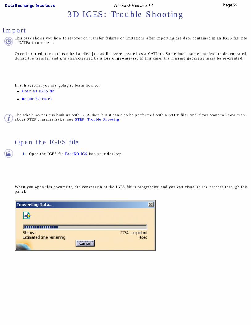
ImportThis task shows you how to recover on transfer failures or limitations after importing the data contained in an IGES file into a CATPart document.
Once imported, the data can be handled just as if it were created as a CATPart. Sometimes, some entities are degenerated during the transfer and it is characterized by a loss of geometry. In this case, the missing geometry must be re-created.
In this tutorial you are going to learn how to: ● Open an IGES file
● Repair KO Faces
The whole scenario is built up with IGES data but it can also be performed with a STEP file. And if you want to know more about STEP characteristics, see STEP: Trouble Shooting
Open the IGES file
1. Open the IGES file FaceKO.IGS into your desktop.
When you open this document, the conversion of the IGES file is progressive and you can visualize the process through this panel:

Eventually, once the transfer is completed (see Show/NoShow Completion Dialog Box for more details), a message similar to this one appears:
Click OK to continue. All the faces reported as KO are put in the geometrical set GeometryFailure .
For each face KO, you will find a FaceKO.xx geometrical set under GeometryFailure. This geometrical set contains the geometric elements of the face. By default it is sent to the NoShow.
Repair KO faces
1. Recall FaceKO#BND_SRF1 from the NoShow and expand it if necessary. It contains the support surface and
boundary curves corresponding to the face.

The reason of the failure is that the inner boundary is described before the outer boundary, in contradiction with the
IGES standard.
2. In Generative Shape Design (for example), select the Join icon .
3. Select the curves of the outer boundary:

Press OK. A Join.1 is created under FaceKO.1.
3. Repeat this step with the curves of the inner boundary:
A Join.2 is created under FaceKO.1.

3. Select the Split icon .
4. Select the surface and Join.1
3. Push the Other side button to keep the inside of the surface.

Press OK. The surface is split by the outer boundary. Split.1 is created under FaceKO.1.

4. Repeat this step with Join.2 and Split.1
Split.2 is created, corresponding to the repaired face.

Before splitting the surface, as no associativity is needed, you can use the Create Datum mode by selecting the Create Datum icon.
5. If necessary, you can move the result surface Split.2 to another geometrical set: Right click the result surface and
select Split.2 object-> Change geometrical set... to move the resulting surface to another geometrical set.
The following dialog box opens. Choose the destination geometrical set:
7. Delete the FaceKO#BND_SRF1 geometrical set. All these elements are however present within the No Show space.
Another possible cause of failure:
The splitting operation has kept the wrong side of the boundary.
● Recreate the correct face by Fill (in datum mode)
As a result, a Surface.xx is created.
You may also extract the surface boundary and untrim the surface to use Split.
You are now ready to create the topology. For more information: ● please refer to the next chapter entitled IGES: Best Practices - How to create a topology
● or use the application Healing Assistant for more complex cases.

Export:
None
3D IGES: Best Practices
Import
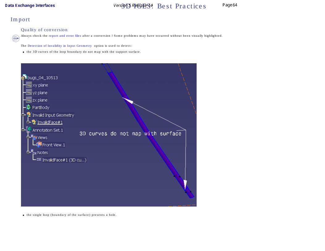
Quality of conversionAlways check the report and error files after a conversion ! Some problems may have occurred without been visually highlighted.
The Detection of Invalidity in Input Geometry option is used to detect:
● the 3D curves of the loop boundary do not map with the support surface.
● the single loop (boundary of the surface) presents a hole.

● two other cases of invalidity:❍ The boundary and the surface are not in the same plane (a transformation matrix is missing). Apply the required transformation, join the boundary and split the surface with the
result join.
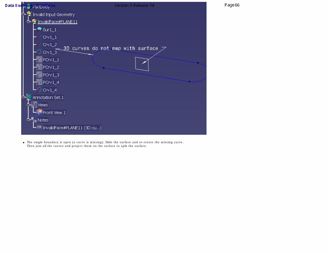
● The single boundary is open (a curve is missing). Hide the surface and re-create the missing curve. Then join all the curves and project them on the surface to split the surface.

How to Create a TopologyThis task shows you how to generate the model topology if it is not contained in the CATPart corresponding to the original IGES file you have imported.
You have seen how to recover a maximum of the face geometry and individual topology, when it failed during the import of either IGES.This scenario will show you how to create solids from IGES faces and also how to join the surfaces of an IGES model into a Part.
It also shows you how to improve the quality of the geometry of the solid obtained thanks to the Healing operation in Generative Shape Design. I
Therefore, this methodology allows you to improve IGES data interoperability and productivity (use of features).It can also be applied to a STEP file, when the failure of the topology transfer occurs (in rare cases) and to improve geometry quality.
Previously, you had 2 scenarios about the repairs of KO faces: ● Open an IGES file
● Repair faces KO

Now, with the following steps you will learn how to close the topology: ● Create a topology
● Analyze the topology
● Healing
● Create a solid
Create a topologyYou may open the file 01_FaceKOrepaired.CATPart.
1. Select all surfaces of GeometricalSet.1 in order to apply the Join operation upon all these elements. The Join operation allows to repair geometry whereas topological healing
allows to close topology.
It is better to select the surfaces in the tree (select Surface.1, then select the last surface holding the Shift key) to have them ordered by their numbers in the Join Definition dialog box.

2. Keep merging distance = 0.001mm and deactivate the connexity Check option. The problem is not yet to check whether the surface is closed or even connex. This will be analyzed
in the following step.
3. Click Preview. An error message is displayed, saying that some surfaces cannot be integrated to the join.
The solution is to withdraw these surfaces.
4. The rejected surfaces are automatically selected in the list, in the Join Definition dialog box and you can use the Remove Mode button.

5. Click Apply.
6. Click OK. The resulting join surface includes all surfaces of GeometricalSet.1 except those that have been rejected.
7. Insert a new Geometrical set and name it SurfacesToAnalyze (for example)
8. Move the rejected surfaces to the new Geometrical set. For this, right click them in the No Show space and select the Change Geometrical set... contextual command.

9. Hide GeometricalSet.1 and display the other geometrical set SurfacesToAnalyze.
10. Check the rejected surfaces. Usually rejected surfaces have a very sharp corner, for instance, a vertex where edges arrive tangent to each other.
11. Reframe on the first surface to recreate (Surface.321 for instance):

12. Create its complete boundary by selecting the Boundary icon in the Operations toolbar.
13. Disassemble the boundary in order to be able to see the curves by using the Disassemble icon in the Join-Healing toolbar. As a result, details about the curves contained in
Surface.321 are displayed in the Specification tree.
14. Untrim the surface to process (Surface.321) by clicking on this icon Click OK when this message appears :
A new element is displayed : SurfaceUntrim.1

15. Recreate the face by Split between Surface.710 and Curve.1, Curve.2 and Curve.9.

16. Join Curve 4, 5, 6 into Join.2
17. Split the surface (in datum mode) with:
● Element to cut: Split.1.
● Cutting element: Join 2.

Repeat the same operations with the other rejected surfaces. You may also recreate only two of them and use asymmetry for the other two.
19. Double click Join.1 (in GeometricalSet.1) to edit it and select the four corrected faces to add them to the list (Add Mode):

20. Click OK.
All the surfaces are now inserted into the join: the topology is complete. You can now delete SurfacesToAnalyze.
Analyze the topologyYou may open the file 02_InitialTopology.CATPart.
1. Activate the Surface boundary display option: select the Tools -> Options... command, click General -> Display in the list of objects to the left of the Options dialog box. Select
the Visualization tab.
The Analysis is based on the free sides of the surface. Free sides may indicate: ● gaps between elements
● missing elements (not converted or not available in original IGES file)
● overlaps (duplicated elements)
● invalid elements (with unexpected shapes)
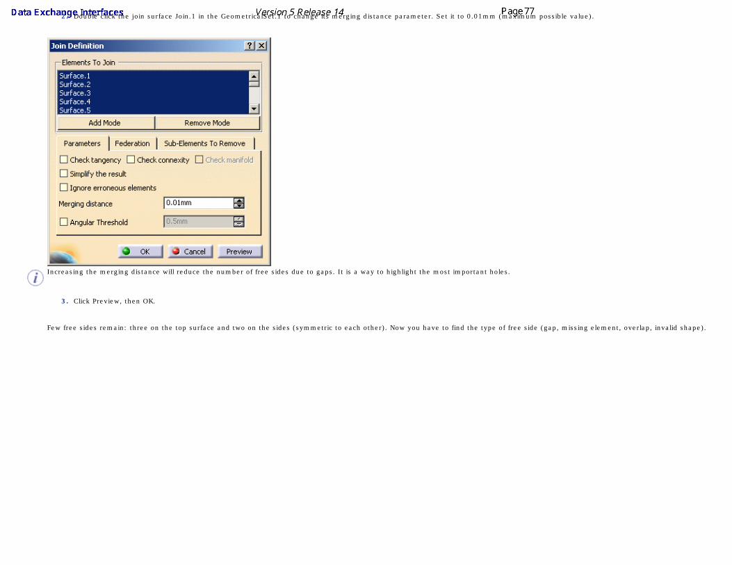
2. Double click the join surface Join.1 in the GeometricalSet.1 to change its merging distance parameter. Set it to 0.01mm (maximum possible value).
Increasing the merging distance will reduce the number of free sides due to gaps. It is a way to highlight the most important holes.
3. Click Preview, then OK.
Few free sides remain: three on the top surface and two on the sides (symmetric to each other). Now you have to find the type of free side (gap, missing element, overlap, invalid shape).

4. Reframe on the side surface surrounded by a free side.

5. Display the No Show space to see the original surfaces.
6. Use the Connect Checker in the Analysis toolbar to measure the distance between the surface (Surface.707) and its neighbors. The maximum distance is 0. It means that the
free side is not due to gap.
7. Select the surface and send it to the visible space. Check it you see a hole instead. There is no hole, it means that this surface was duplicated. You have to delete one of the
surfaces.
8. Remove the surface 707 from Join.1, then delete it.

9. Repeat these steps with surface 706.
10. Reframe on the area shown below and display the No Show space to see the original surfaces (Surface.526, Surface.534).
They are obviously incorrect, their shapes look strange. The shaded display is typical of a problem in the definition of the boundaries (missing boundary curves, wrong order).
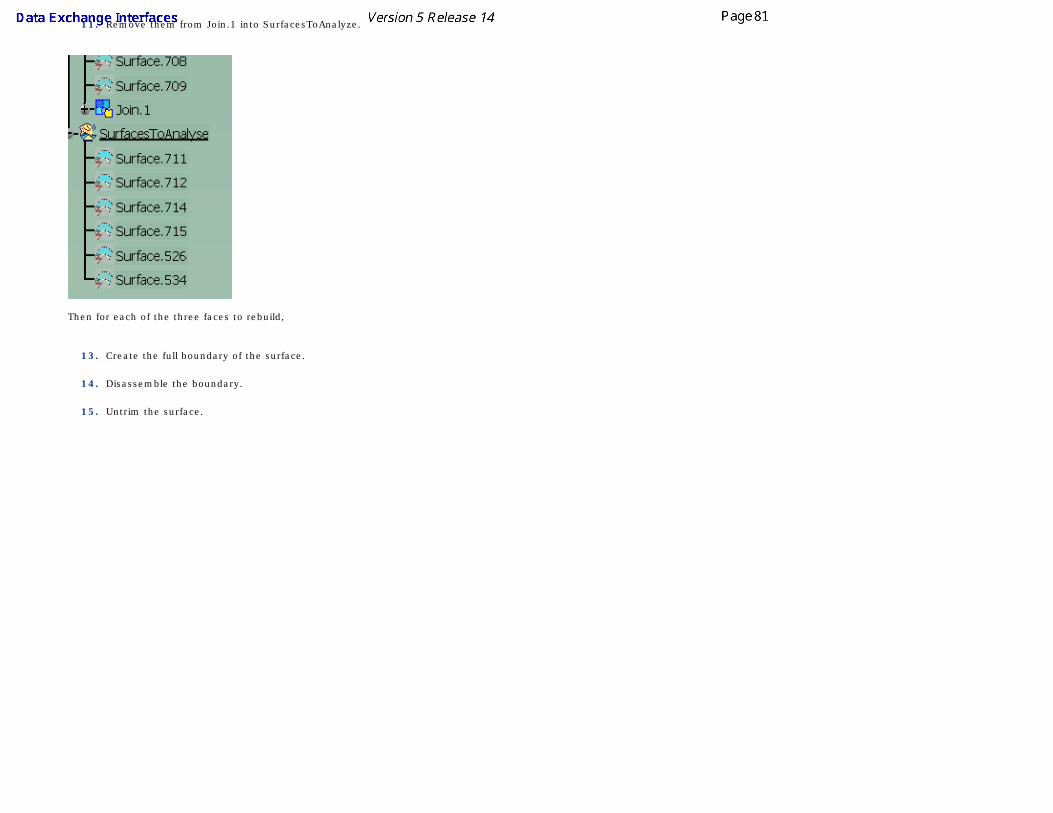
11. Remove them from Join.1 into SurfacesToAnalyze.
Then for each of the three faces to rebuild,
13. Create the full boundary of the surface.
14. Disassemble the boundary.
15. Untrim the surface.

16. Check the boundary curves and create the missing ones
17. Recreate the correct surfaces by Split (in datum mode).
18. Add the recreated surfaces to Join.1.
The surface has now no visible free side, but there might be very small holes impossible to detect visually.
To make sure that the surface is closed: Select Join.1 and click the Boundary icon. If the selected surface is closed, you get an explicit message.
It means that the surface is closed within 0.1mm. You may now try to reduce the merging distance to find the minimum value that gives a closed surface.
Change the merging distance to 0.01mm and check for free sides: The surface is closed within 0.01mm. Check with 0.005mm: The surface has visible free sides.Check with 0.008mm: The surface is closed within 0.008mm. This distance is a good evaluation of the model accuracy.
Healing

You may open the file 03_ClosedTopology.CATPart.
At that stage, you may decide that the evaluated accuracy is good enough but you may also create a solid and use the Healing to reduce the gaps between surfaces by actually modifying (deforming) the surfaces.
1. Select the Healing icon .
2. Select Join.1.
3. Give the value of the tolerance found in the previous step (Merging distance is 0.008mm in this case).
4. Click OK.
The surface is now both topologically and geometrically closed.
Create a solidYou may open the file 04_HealedTopology.CATPart.

1. Start a Part Design workbench.
2. Select the Close Surface icon in the Surface-Based Features toolbar.
3. Select Join.1 or Healing.1. The following message confirms the operation:
4. Click OK.
The solid is created and ready for use. The process is now completed.
Export
Large AssembliesTo export a large V5 Assembly in IGES, we recommend that you open it with the Work with the cache system option active (Tools/Options/Infrastructure/Product Structure/Cache Management/Work with the cache system): When this option is active, the referenced CATPart documents are loaded only during their transfer.

3D IGES: FAQHere is a non-exhaustive list of Frequently Asked Questions about the IGES export and import process. The most common problems are gathered here to help trouble-shooting.
Import
● Question : the application cannot open the IGES file and returns an "invalid input file" error message, what can I do?
●
Answer : As the error message suggests , the IGES file is indeed a poor quality IGES file that cannot be opened. The best thing to do is to contact the provider of the IGES file and ask for a more decent file.
● Question: the application crashes when I open the IGES file with a "Run Time Exception", why ?
● Answer : It is obviously a bug that was not fixed on the release you are using. If you do not use the latest release, you can consider upgrading or contact your local support.

● Question : I get a 'Low memory state' warning message and my IGES file is not totally converted.
● Answer : there is not enough memory to convert the file completely and all the remaining entities are skipped. We recommend to use Windows NT4SP06 (and above) for big IGES files and use at least 1 GB of RAM and 2 GB of SWAP.
● Question : I opened my IGES file successfully but I have some KO faces that were moved to the NoShow section, what was wrong?
●
Answer : there could be many reasons why KO faces are returned but it is usually due to the fact that it was not possible to recreate the geometry
contained in the IGES file. To avoid those KO faces, you can try and import the IGES using a different import option for Representation for boundaries of
trimmed and bounded surfaces.
If you still have KO faces, you may consider repairing those faces using the methodology described in the chapter 3D IGES: Trouble Shooting
● Question : all the dimensions of my IGES file were multiplied by 25.4, why ?
● Answer : the most common cause for this problem is a problem in the header of the IGES file which is not correct. Therefore, the application can not
read correctly the dimension system used by the user and takes the 'inch' as the default system. That explains why all the dimensions are multiplied by
25.4. Then you can either modify manually the IGES file to repair it or you can ask the provider of the IGES file to provide a good quality file

● Question : I have a KO Face: in the KO-Body, I have only Surfaces (no curve); in the .err file, I can read There is no 3D curve....
How can I repair my face ?
Answer: The Surface must be a C2 B-Spline. The reason of the problem is that there is not the 3D-representation for the curves in the IGES File.
The Face type is 144. The Boundary type is 142. This Boundary should reference two Curves Representations :
● First, a 2D-Parametric Curves Representation: OK, in our case.
● Then, a 3D Curves Representation: Missing in our case!
CATIA V5 only uses the 2D representation if the B-Spline Surface is C2-continuous.
Here, the B-Spline Surface is not C2. CATIA V5 must cut it in C2 Surfaces and cannot use the 2D Curves Representation.
With Continuity Optimization of Curves and Surfaces option, B-Spline Surfaces are approximated to be C2-continuous and 2D curves can be used (B-Spline Surfaces are C2).
All Faces are OK !
● Question : Even with correct IGES Options, I still have a KO Face : in the KO-Body, I have only one not-cut B-Spline Surface (no curve); in the .err file, I can read There is no 3D curve....
How can I repair my face ?

Answer: The IGES File is invalid and has 2 problems:● First, There is NO 3D Curves Representation.
● and the 2D Curves Representation is incorrect :
For the 2D Curves, the Entity Use Flag, in the Status Number, should be "05" for "2D-Parametric". In the IGES File, this flag is "00", which means 3D Curves! Replace the incorrect flag "00" by "05" for all 2D Curves in the IGES file.
Export
● Question : When examining my .rpt file, I see I have some KO faces , what should I do?
● Answer : KO faces when exporting may be caused by a corrupted CATPart. You can try and use the CATDUA utility to see if there is nothing to be done on
the CATPart itself. If, despite all, you still get KO faces when exporting to IGES, please contact your local support.
● Question : The IGES file created by my application is not correctly opened by my CAD package, what should I do?
● Answer : You can try to use the export with the two available options for Curve and surface type : Standard and BSpline
The BSpline option may give better results with some CAD systems and the Standard option give better results with others.
If the result is still bad with the receiving system, you may want to investigate if the CATPart is not corrupted and use the CATDUA program to upgrade the
CATPart. Finally, if the result is still not the expected one, it could be a problem with the CAD receiver system itself.
● Question : I am losing some parts of my assembly while exporting my CATProduct to IGES, why ?

● Answer : Make sure that you do not have any foreign parts included in your CATProduct like STL files or Parasolid files...etc. Those files do not contain any V5 information except the visualization information and therefore it is impossible to export them as IGES file. If you have CATIA V4 .models in your CATProduct, make sure to have them migrated to V5 before exporting to IGES.

3D IGES: VBScript macros
You can automate Data exchanges with IGES using VBScript macros, either at import or at export
Import
1. Create a RunTime window (window in which all runtime variables a set)
2. Type the command:
cnext -macro MyMacro.CATScript
where MyMacro.CATScript is the VBScript macro you want to execute
● The input files must be writable (not read only). Otherwise the system will display an information box and wait for an acknowledge.
● The output file must not exist in the output directory otherwise the system will ask for a confirmation to overwrite the file and wait for an
acknowledge.
You can transfer several files within the same VBScript macro, but it is recommended to do only one transfer per VBScript macro.
ExampleVBScript macro for implementing a IGES file
Language="VBSCRIPT"
Sub CATMain()
Dim Document0 As Document
' Reading an IGES file
Set Document0 = CATIA.Documents.Open( "E:\tmp\Box.igs" )
' Saving the corresponding CATPart
CATIA.ActiveDocument.SaveAs "E:\tmp\Box"
CATIA.Quit
End Sub
Export
1. Create a RunTime window (window in which all runtime variables are set):
2. Type the command:
cnext -macro MyMacro.CATScript
where MyMacro. CATScript is the VBScript macro you want to execute.

The input files must be writable (not read only). Otherwise the system will display an information box and wait for an acknowledge.
The output file must not exist in the output directory otherwise the system will ask for a confirmation to overwrite the file and wait for an acknowledge.
You can transfer several files within the same VBScript macro, but it is recommended to do only one transfer per VBScript macro
Example
VBScript macro for exporting a file to IGES
Language="VBSCRIPT"
Sub CATMain()
Dim PartDocument0 As Document
' Reading a CATPart file
Set PartDocument0 = CATIA.Documents.Open ( "E:\tmp\Box.CATPart" )
' Saving the part in a IGES file
PartDocument0.ExportData "E:\tmp\Box2", "igs"
CATIA.Quit
End Sub

2D IGES Interface
2D IGES: Import2D IGES: Export
2D IGES: Report File2D IGES: Trouble Shooting
2D IGES: Best Practices2D IGES: FAQ
2D IGES: VBScript Macros

Importing a 2D IGES File into a CATDrawing
This task shows you how to import into a CATDrawing document the data contained in a 2D IGES file. Once imported, the data can be handled just as if it were created as a CATDrawing.
The table entitled What about the elements you import ? provides information on the entities you can import.
You can find further information in the Advanced Tasks:
● Trouble Shooting,
● Best Practices,
● FAQ,
● Macros
● and in the Customizing 2D IGES Settings chapter.
Statistics about each import operation can be found in the report file.
1. Select the File -> Open command.
The File Selection dialog box is displayed.
2. If the directory contains many different types of files you may wish to set the .ig2 extension in the Files of type field. This displays all files with the extension "ig2" contained
in all the selected directory.
3. Select the .ig2 file of your choice and click Open.
This creates a new document similar to a CADrawing document in all respects and containing all 2D geometry and annotations. The data is now available in your session.
Several 2D IGES import options can be customized: ● Standards
● Unit of the file
● Destination view
● Create end points
● Convert dimensions as

Format
V5 determines systematically and automatically the most suitable format (A0 ISO, A1 ISO, etc.) for each sheet (layout) i.e. V5 chooses the smallest format in which the drawing can be totally included:
● If the standard is ISO, V5 chooses the format among A0, A1, A2, etc.
● If the standard is ANSI, V5 chooses the format among A, B, C, etc.
● If no standard format fits the sheet, the format is set to the largest one i.e. A0 ISO and made invisible with a message "No standard format can be applied to this sheet" in the report file.
● If you are not satisfied with this automatic result, use the Page Setup command to modify the format.
Information on what has been determined automatically is written in the report file:
For more information on Formats, see the Defining a Sheet chapter in the Generative Drafting User's Guide.
Code pages
DBCS (Double Byte Character Set) Supported Code Pages are:
● 932 (Japanese)
● 936 (Simplified Chinese)
● 950 (Traditional Chinese)
949 (Korean) is not supported.
Fonts
Fonts are mapped with those defined by default in the standard. See the Generative Drafting User's Guide for more information.
Report File

After the recovery of 2D IGES files, the system generates:
● a report file (name_of_file.rpt) where you can find references about the quality of the transfer
These files are created in a location referenced by
● the USERPROFILE variable on NT. Its default value is Profiles\user\Local Settings\Application Data\Dassault Systemes\CATReport on NT (user
being you logon id)
Always check the report file after a conversion ! Some problems may have occurred without been visually highlighted.
What about the Elements You Import?To make sure the elements you need to handle in your session are those you expected, here is a list presenting the IGES data supported when imported into a CATDrawing document:
Element type Element number in IGES format
circular pattern 100
composite curve 102
conic arc 104
copious data 106
line 110
parametric spline curve 112
point 116
transformation matrix 124
rational B-spline curve 126
offset curve 130
angular dimension 202
arc length dimension 204
diameter dimension 206
flag note 208
general label 210
general note 212
leader 214
linear dimension 216
point dimension 220
radius dimension 222

general symbol 228
sectioned area 230
subfigure definition (detail) 308
associativity instance (group) 402
drawing 404
properties 406
single subfigure instance (ditto) 408
view 410

Exporting CATDrawing Document to an IGES 2D file
This task show you how to save in an IGES 2D file the data contained in a CATDrawing document.
● IGES 5.1 is the standard used for the generation.
You can find further information in the Advanced Tasks: ● Trouble Shooting,
● Best Practices,
● FAQ,
● VBScript Macros
● and in the Customizing 2D IGES Settings chapter.
1. Open the CATDrawing document to be saved in IGES format.
2. Select the File -> Save As... command. The Save As dialog box is displayed.
3. Specify the name of the document in the File name: field.
4. Set the .ig2 extension in the Save as type field.
5. Click the Save button to confirm the operation.
The export unit depends on the current unit of your session (see the Tools -> Options->Parameters and Measures/Units panel). ● If the current unit belongs to the metric system (millimeter, centimeter, meter, ...) the export unit is the millimeter.
● If the current unit belongs to the Anglo-Saxon system (inch, foot, ...) the export unit is the inch.
So select the required type of session unit to export your data in one system or the other.
Limitations in the case of a multi-sheet drawing:● When there are several sheets, the name of the file really created is not that entered by the user in the Save as dialog box, since it is concatenated with
that of the sheet. Therefore, it is not possible to check if a file with the same name already exists and any existing file will be overwritten without warning.
● If one of the sheets contains no geometry, no 2D IGES file is created.
● The number of characters of the name of the result file is limited to 150.
● If the name of a sheet contains one of the following characters or blank space, the character will be replaced with _ (underscore).
For more information, please refer to the Exported Sheets option

Report File
After exporting the data to 2D IGES files, the system generates:
● a report file (name_of_file.rpt) where you can find references about the quality of the transfer.
These files are created in a location referenced by
● the USERPROFILE variable on NT. Its default value is Profiles\user\Local Settings\Application Data\Dassault Systemes\CATReport on NT (user being
you logon id)
What About the Elements You Export?
Structured export option only:● Dimensions are exported as graphic blocks and are editable as such.
Semantic export option only:● Linear dimensions are exported as true dimensions and editable as such.
Linear dimensions with:● underlined text,
● text with frame,
● numerical values and decimal values given as fractions,
● funnels,
● half-dimensions,
● with an arrow pointing to the dimension line
are exported as sub-figures.
● The texts of those dimensions (linear only) are exported with the 2D IGES corresponding font.
● Circular, angular and curvilinear dimensions are still exported as graphic blocks.

Semantic and Structured export options:● Show/No Show:
The V5 elements placed in the No Show are not exported. The visible elements are exported.
● Layers:
In Structured and Semantic modes, layers are automatically exported. The number of the 2D IGES layer is the number of the V5 layer.
● Filters:
To avoid missing geometries at export, we recommend that you activate either the filter All Visible or the filter None.
● Texts:
● All texts are exported as texts (even dimension texts in the case of dimensions exported as graphic blocks and annotations),
● All texts are exported and mapped automatically with the 2D IGES corresponding font.
● Kanji characters are exported with the 2D IGES 2001 font.
● The line thickness is automatically mapped, based on V5 current thickness.
The table below sets the mapping between the CATDrawing file elements and the resulting IGES 2D elements.
V5 2D IGES
Element Sub-type Graphic export Structured and Semantic export
Structures
Sheet One 2D IGES file per sheet (see option)
Views
Interactive view
The structure is not exported.
Note that raster views are not supported.
The structure is not exported.
Generative view
The structure is not exported. All the geometric entities of the view are gathered into a single subfigure.
The above applies to CGR, approximate, exact views.
Note that raster views are not supported.
Detail (Component)Details are retrieved through their Dittos. A Detail not referenced by a Ditto is thus lost, a Detail referenced by several Dittos is duplicated in subfigures. The entities included in a Detail are not structured into subfigures.
Ditto (Instance) The graphical representation of each Ditto is exported to a subfigure
Attributes

Unit The unit of the output file depends on the session current units
Show/NoShow Only visible elements are exported
Pick/NoPick NoPick ignored
Line Type Automatic mapping
Line Thickness Automatic mapping
Marker type Ignored
Color Automatic color
Text attributes
Font
Exported implicitly through the graphic representation of text.
Only the contour of characters is exported.
Default mapping
Bold, italic Not supported
Underlined Text + line
Space (x-scale) Space
Height Height
Justification Justification
Flip Flip
Frame Text + geometry
Layer Not supported Layer
Annotations
Dimension
Linear
The geometrical basic elements of each representation are exported.
If the representation includes
Structured mode:
Each graphical representation of the elements is exported to a subfigure
Semantic mode:
Linear dimensions are exported as such.
Circular
Angular
Curvilinear
Structured and Semantic mode:
Each graphical representation of the elements is exported to a subfigure
Axis line Line with the suitable line type
Center Line
Thread
Welding symbol
Coordinate dimension

filled areas, only the contour is exported.
Each graphical representation of the elements is exported to a subfigure. If the representation includes filled areas, only the contour is exported.
Balloon
Datum Target
Datum Feature
GDT
Roughness symbol
Table
Leader
Arrow
Callout
TextOne TEXT (or several TEXTS in case of font or attribute changes) + geometry gathered into a subfigure (see text attributes)
Area fill Pattern
The geometrical elements making the hatches are gathered into a subfigure
Hatching pattern
Dotting pattern
Coloring pattern Only the contour of the hatches is exported Only the contour of the hatches is exported into a subfigure
Geometry
Curve Point POINT (116)
Line LINE (110)
Polyline 2D POLYLINE (106)
Circle CIRCLE (100)
Arc ARC (100)
Spline 2D POLYLINE (106)
NURBS 2D POLYLINE (106)
Ellipse 2D POLYLINE OR ELLIPSE (104)
Hyperbola 2D POLYLINE (106)
Parabola 2D POLYLINE (106)
Constraints Not supported
Miscellaneous
OLE link Not supported

Picture (bitmap...) Not supported
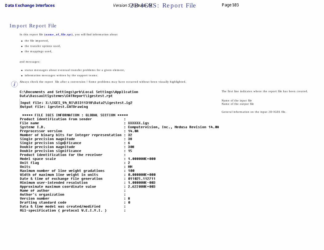
2D IGES: Report File
Import Report File
In this report file (name_of_file.rpt), you will find information about
● the file imported,
● the transfer options used,
● the mappings used,
and messages:
● status messages about eventual transfer problems for a given element,
● information messages written by the support teams.
Always check the report file after a conversion ! Some problems may have occurred without been visually highlighted.
The first line indicates where the report file has been created.
Name of the input fileName of the output file
General information on the input 2D IGES file.

List of the options used:
Status messages
See the Trouble Shooting, the Best Practices and the FAQ chapters on how to solve those problems.
Automatic choice of format and unit
Summary of the conversion results.
In this example, 112 entities of type 106 have been transferred successfully.
See the Best Practices chapters on how to solve those problems.

Transcription time.
Export Report File

In this report file (name_of_file.rpt), you will find information about
● the file exported,
● the transfer options used,
and messages:
● status messages about eventual transfer problems for a given element,
● information messages written by the support teams.
Always check the report file after a conversion ! Some problems may have occurred without been visually highlighted.
The first line indicates where the report file has been created.
Name of the input fileName of the output file
List of the options used in the settings:
The options may be changed in the option dialog box.
Status messages
This section is empty at export
Summary of the conversion results.
In this example, 4 V5 lines have been successfully transferred, and so on.
Transcription time.

2D IGES: Trouble Shooting
Import:
None
Export:
None

2D IGES: Best Practices
Import
Quality of conversionAlways check the report file after a conversion ! Some problems may have occurred without been highlighted.
Export
None

2D IGES: FAQ
Import
● Question: In export/import loops, the format of the model is modified at the re-import in V5.
● Answer: the format is modified because V5 computes the best possible format to adjust it to the model.
Export
None

2D IGES: VBScript Macros
You can automate Data exchanges with IGES using VBScript macros, either at import or export,
Import
1. Create a RunTime window (window in which all runtime variables a set)
2. Type the command:
cnext -macro MyMacro.CATScript
where MyMacro.CATScript is the VBScript macro you want to execute
● The input files must be writable (not read only). Otherwise the system will display an information box and wait for an acknowledge.
● The output file must not exist in the output directory otherwise the system will ask for a confirmation to overwrite the file and wait for an acknowledge.
You can transfer several files within the same VBScript macro, but it is recommended to do only one transfer per macro.
Example
VBScript Macro for implementing a IGES file
Language="VBSCRIPT"Sub CATMain()Dim Document0 As Document' Reading an IGES fileSet Document0 = CATIA.Documents.Open ( "E:\tmp\Box.igs" )' Saving the corresponding CATDrawingCATIA.ActiveDocument.SaveAs "E:\tmp\Box"CATIA.QuitEnd Sub
Export

1. Create a RunTime window (window in which all runtime variables are set):
2. Type the command:
cnext -macro MyMacro.CATScript
where MyMacro. CATScript is the VBScript macro you want to execute:
● The input files must be writable (not read only). Otherwise the system will display an information box and wait for an acknowledge.
● The output file must not exist in the output directory otherwise the system will ask for a confirmation to overwrite the file and wait for an acknowledge.
You can transfer several files within the same VBScript macro, but it is recommended to do only one transfer per VBScript macro.
Example
VBScript macro for exporting a Part file to IGES
Language="VBSCRIPT"
Sub CATMain()
Dim DrawingDocument0 As Document
' Reading a CATDrawing file
Set DrawingDocument0 = CATIA.Documents.Open ( "E:\tmp\draw.CATDrawing" )
' Saving the Drawing in a 2D IGES file
DrawingDocument0.ExportData "E:\tmp\draw2", "ig2"
CATIA.Quit
End Sub

DXF/DWG Interface
DXF/DWG: ImportDXF/DWG: Export
DXF/DWG: Report FileDXF/DWG: Trouble Shooting
DXF/DWG: Best PracticesDXF/DWG: FAQ
DXF/DWG: VBScript Macros

Importing a DXF/DWG file into a CATDrawing
This task lets you quickly see how to import or to insert the 2D geometric data contained in a DXF file into a CATDrawing document. Once imported, the data can be handled and edited just as if they had been created in a Drafting session using 2D geometry creation commands.
The table entitled What about the elements you import ? provides information on the entities you can import.
You can find further information in the Advanced Tasks:
● Trouble Shooting,
● Best Practices,
● FAQ,
● VBScript Macros
and in the Customizing DXF/DWG Settings chapter.
Statistics about each import operation can be found in the report file created.
Open your session (Open your CATDrawing document if you want to insert a DXF file.).
1. To import an existing DXF/DWG file, select the File-> Open items.
The File Selection dialog box is displayed:
1. To insert a DXF/DWG file in an existing CATDrawing document, select the
Tools -> Import External Format.
The File Selection dialog box is displayed:
2. Select the.dxf/.dwg extension from the field called Files of type.
All .dxf/.dwg files contained in the selected directory are now displayed.
3. Click the .dxf/.dwg file of your choice. For example, click the draw1.dxf file.
4. Click Open.
In import mode, a CATDrawing file is created which contains all the geometry included in the DXF/DWG file. This .CATDrawing file becomes the current document.
In insertion mode, the geometry of the DXF/DWG file is created in a new view of the current sheet.

Import of multiple viewports and layouts
The default behavior has been improved for better results. If the model is referenced, at least partially, by one or several viewports, the model is not created in a sheet of its own. Only layouts are created. They will contain eventual viewports.
CATIA does not create empty viewports or layouts.
Format
V5 determines systematically and automatically the most suitable format (A0 ISO, A1 ISO, etc.) for each sheet (layout) i.e. V5 chooses the smallest format in which the drawing can be totally included:
● If the standard is ISO, V5 chooses the format among A0, A1, A2, etc.
● If the standard is ANSI, V5 chooses the format among A, B, C, etc.
● If no standard format fits the sheet, the format is set to the largest one i.e. A0 ISO and made invisible with a message "No standard format can be applied to this sheet" in the report file.
● If you are not satisfied with this automatic result, use the Page Setup command to modify the format.
Information on what has been determined automatically is written in the report file:
For more information on Formats, see the Defining a Sheet chapter in the Generative Drafting User's Guide.
Code pages
DBCS (Double Byte Character Set) Supported Code Pages are:
● 932 (Japanese)
● 936 (Simplified Chinese)
● 950 (Traditional Chinese)

949 (Korean) is not supported.
Customization
Import of a DXF/DWG file can be improved by customization:
DXF/DWG specific import settings are:
● Standards. The lists of attributes are not the same in V5 and AutoCAD. A DXF mapping standard file is used to come as close as possible to the AutoCAD attributes, or to switch them to V5 attributes.
● Unit of the file
● Papers Spaces and Model Space
● Create end points
● Convert dimensions as
The definitions of dimensions are not the same in V5 and AutoCAD. This option is used to give priority either to the graphic closeness or to the re-usability in V5.
Report File
After the recovery of DXF/DWG files, the system generates:
● a report file (name_of_file.rpt) where you can find references about the quality of the transfer
This file is created in a location referenced by
● the CATUserSettingPath USERPROFILE variable on NT. Its default value is Profiles\user\Local Settings\Application Data\Dassault
Systemes\CATReport on NT (user being you logon id)
● the HOME variable on UNIX. Its default value is $HOME/CATReport on UNIX.
Always check the report file after a conversion ! Some problems may have occurred without been visually highlighted.
What About The Elements You Import ? Version 5 supports DXF/DWG formats version 12,13, 14 and Autocad2000, Autocad2000i and Autocad2002.
To make sure the elements you need to handle in your session are those you expected, here is a list presenting the DXF/DWG data supported when imported into a CATDrawing file.

DXF/DWG element DXF/DWG sub-type V5 element Notes
Geometry
point Point
line Line
ray None
xline None
circle Circle
arc Arc
ellipse Ellipse
polyline/2D polyline/lightweight polyline non adjustable width, made of line segments Polyline Not editable in V5
non adjustable width, made of line and arc segments
segments and arc with no structure Structure is lost
adjustable width Filled area (pattern) Structure is lost
fit curve Polyline
mline Lines Structure and closing attributes are lost
spline NURBS Not editable in V5
3D face none
3D solid none
Annotations
text Text
mtext Text Changing fonts, changing attributes and line break are not taken into account
Arc aligned text none
rtext none

dimensions aligned, linear and rotated, radius and diameter, angular, ordinate (x or y)
According to option:
dimension or
details or
geometry+texts
See dimensions
In a few "dimensions" cases, the text of the dimension can be a text with an associative link
In all "dimensions" cases, the geometry support is in No Show
leader Line + text DXF Leaders are imported as simple lines. The arrow head and the line under the text are lost
tolerance none
hatch non-associative Filled area (pattern)
associative Filled area (pattern) The contour of the hatch is created in the No Show and the associativity is created with this hidden contour.
solid Filled area (colored)
block attribute Text
Structures
block Detail The details are created in a new Detail Sheet named "Imported Details".
insert (Block Reference) Ditto If the insert is defined with different scales, on x-axis and y-axis, no detail instance is created but only the geometry is transferred.
group none The structure of the group is lost whereas its contents is transferred
viewport View see above
Layout (paper space) Sheet see above
OLE frame none

proxy none
region none
Attributes
color Color see Standards
Line weight Line weight see Standards
line type Line type see Standards
point markers Point type Markers may be different since V5 and AutoCAD do not have the same markers.
layer Layer Invisible layers are gathered in a filter named Invisible Imported Layers.
Visible layers are gathered in a filter named Visible Imported Layers.
font Font see Standards
Pattern Pattern Automatic mapping
BYBlock attribute Attribute The value of the attribute of the block is set to a default value
BYLAYER attribute Attribute The value of the attribute of the layer is applied to each element imported

Exporting a CATDrawing Document's Data into a DXF or DWG File
This task quickly shows you how to export the data contained in a CATDrawing document into a DXF file.
● Drawing Interchange Format (DXF) files enable the interchange of drawings between Generative Drafting Version 5 and Version 4 or with other programs.
● DXF files correspond to ASCII format and DWG to binary format.
● Version 5 provides a simple method to export the data contained in a CATDrawing document either in a DXF file or in a DWG file.
● Version 5 supports DXF/DWG formats version 12, 13, 14 and Autocad2000.
You can find further information in the Advanced Tasks: ● Trouble Shooting,
● Best Practices,
● FAQ,
● VBScript Macros.
● and in the Customizing DXF/DWG Settings chapter.
Open a CATDrawing document.
1. Select the File, Save As item.
The Save As dialog box is displayed:
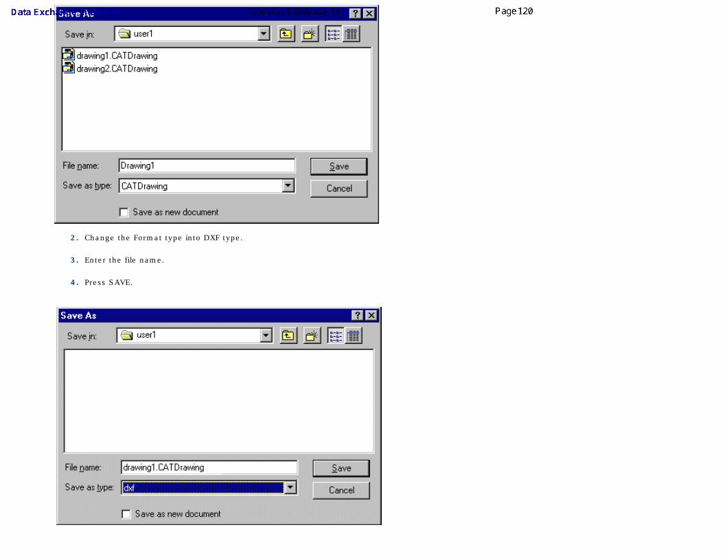
2. Change the Format type into DXF type.
3. Enter the file name.
4. Press SAVE.

The export unit depends on the current unit of your session (see the Tools -> Options->Parameters and Measures/Units panel). ● If the current unit belongs to the metric system (millimeter, centimeter, meter, ...) the export unit is the millimeter.
● If the current unit belongs to the Anglo-Saxon system (inch, foot, ...) the export unit is the inch.
So select the required type of session unit to export your data in one system or the other.
Limitations in the case of a multi-sheet drawing:● When there are several sheets, the name of the file really created is not that entered by the user in the Save as dialog box, since it is concatenated with
that of the sheet. Therefore, it is not possible to check if a file with the same name already exists and any existing file will be overwritten without warning.
● If one of the sheets contains no geometry, no DXF file is created.
● The number of characters of the name of the result file is limited to 150.
● If the name of a sheet contains one of the following characters or a blank space, the character will be replaced with _ (underscore).
You can customize the DXF specific export options:
● exported sheets (in the case of a multi-sheet drawing)
● version
● export mode
Report file
After the exporting data to DXF/DWG files, the system generates:
● a report file (name_of_file.rpt) where you can find references about the quality of the transfer
This file is created in a location referenced by
● the USERPROFILE variable on NT. Its default value is Profiles\user\Local Settings\Application Data\Dassault Systemes\CATReport on NT (user being
you logon id)
● the HOME variable on UNIX. Its default value is $HOME/CATReport on UNIX.
What About the Elements You Export?
All export options:
If the sheet to export contains no geometry, or only non supported entities, no DXF/DWG file is generated.

Structured export option only:
● Dimensions are exported as graphic blocks and are editable as such.
Semantic export option only:● Circular, linear and angular dimensions are exported as true dimensions and editable as such.
● The texts of those dimensions are exported with the STANDARD style and the isocp.shx font.
● The tolerances of dimensions are now exported.
● The "upper" and "down" texts are not taken into account.
● Dual values are not exported.
● Half-dimensions are exported as simple dimensions (the visibility attributes of the extension lines and arrows are not exported).
● Circular extension lines are not exported.
● Half-dimensions are exported as graphic blocks.
Semantic and Structured export options:● Show/No Show:
The V5 elements placed in the No Show are not exported. The visible elements are exported.
● Layers:
In Structured mode, layers are automatically exported. The name of the DXF/DWG layer derives from the number of the V5 layer.
● Filters:
To avoid missing geometries at export, we recommend that you activate either the filter All Visible or the filter None.
● Texts:
● All texts are exported as texts (even dimension texts and annotations) with a fit justification,
● All texts are exported with the STANDARD style and the isocp.shx font with the exception of geometric tolerance symbols that are exported with the GDT specific style and amgdt.shx font, with the corresponding mapping.
● The symbols diameter Ø, degree °, plus/minus ± are inserted with the standard tags.
● Unicode characters are exported with the \U+ tag. You have to redefine the STANDARD style in AutoCAD to reference an unicode font.

The table below sets the mapping between the CATDrawing file elements and the resulting DXF 2D elements.
V5 DXF/DWG
Element Sub-type Graphic export Structured and Semantic export
Structures
Sheet
One DXF file per sheet (see option)
The graphical representation of each file is transferred to the space of the AutoCAD model
Views
Interactive view
The structure is not exported.
Note that raster views are not supported.
The structure is not exported.
Generative view
The structure is not exported. All the geometric entities of the view are gathered into a single Insert/Block.
The above applies to CGR, approximate, exact views.
Note that raster views are not supported.
Detail (Component)Details are retrieved through their Dittos. A Detail not referenced by a Ditto is thus lost, a Detail referenced by several Dittos is duplicated in BLOCKS. The entities included in a Detail are not structured into sub-blocks.
Ditto (Instance) The graphical representation of each Ditto is exported to an INSERT/BLOCK
Attributes
Unit The unit of the output file depends on the session current unit
Show/NoShow Only visible elements are exported
Pick/NoPick NoPick ignored
Line Type Automatic mapping
Line Thickness Automatic mapping
Marker type Ignored
Color Automatic color
FontDefault mapping with font isocp.shx (fixed)For Kanji or unicode characters see Trouble Shooting

Text attributes
Exported implicitly through the graphic representation of text.
Only the contour of characters is exported.
Bold, italic Not supported
Underlined Text + line
Space (x-scale) Space
Height Height
Justification Justification
Flip Flip
Frame Text + geometry
Layer Not supported Layer
Annotations
Dimension
Linear
Circular
Angular
The geometrical basic elements of each representation are exported
Structured mode:
Each graphical representation of the elements is exported to an INSERT/BLOCK
Semantic mode:
Linear, angular and circular dimensions are exported as such.
Curvilinear In both modes, each graphical representation of the elements is exported to an INSERT/BLOCK
Axis line Line with the suitable line type
Center Line
Each graphical representation of the elements is exported to an INSERT/BLOCK
Thread
Welding symbol
Coordinate dimension
Balloon
Datum Target
Datum Feature
GDT

Roughness symbol
Table
Leader
Arrow
Callout
TextOne TEXT (or several TEXTS in case of font or attribute changes) + geometry gathered into an INSERT/BLOCK (see text attributes)
Area fill Pattern
The geometrical elements making the hatches are gathered into an INSERT/BLOCK
Hatching pattern
Dotting pattern
Image pattern Only the contour of the hatches is
exported Only the contour of the hatches is exported into an INSERT/BLOCK
Colouring pattern
Geometry
Curve Point POINT
Line LINE
Polyline 2D POLYLINE
Circle CIRCLE
Arc ARC
Spline 2D POLYLINE
NURBS 2D POLYLINE
Ellipse 2D POLYLINE OR ELLIPSE
Hyperbola 2D POLYLINE
Parabola 2D POLYLINE
Constraints Not supported
Miscellaneous
OLE link Not supported
Picture (bitmap...) Not supported

DXF/DWG: Report File
Import Report File
In this report file (name_of_file.rpt), you will find information about
● the file imported,
● the transfer options used,
● the mappings used,
and messages:
● status messages about eventual transfer problems for a given element,
● information messages written by the support teams.
Always check the report file after a conversion ! Some problems may have occurred without been visually highlighted.
The first line indicates where the report file has been created.
Name of the input fileName of the output file
List of the options used in the settings:
The options may be changed in the option dialog box.

Status messages
See the Trouble Shooting, the Best Practices and the FAQ chapters on how to solve those problems.
The syntax of those messages is the following:
<E> Type "hatch" Identifier "8434" This element was not transferred
Message Type Element Type Identifier Element Status/Information Text
Message Type is either Error, Warning or Information.
● Error means that there is a failure.
● Warning means that there may be a failure.
● Information informs you of the possible cause of failure.
Element Type is the type of the DXF/DWG element processed.
Element Handle is the hexadecimal number referencing the DXF/DWG element processed.
Element Status/Information Text is the informative part of the message.
Automatic choice of format and unit
List of the mappings used in that operation for the line types and the fonts.
The mappings may be changed in the standards.

Only those actually used are listed.
● The report file does not yet indicate whether the mapping is the default one or a customized one.
● There is no information yet about an automatic Thickness/Thickness mapping.
Summary of the conversion results.
In this example, 126 hatches have been transferred successfully, and 5 have failed.
See the Trouble Shooting, the Best Practices and the FAQ chapters on how to solve those problems.
Transcription time
Export Report File

In this report file (name_of_file.rpt), you will find information about
● the file exported,
● the transfer options used,
and messages:
● status messages about eventual transfert problems for a given element,
● information messages written by the support teams.
Always check the report file after a conversion ! Some problems may have occurred without been visually highlighted.
The first line indicates where the report file has been created.
Name of the input fileName of the output file
List of the options used in the settings:
The options may be changed in the option dialog box.
Status messages
This section is empty at export
Summary of the conversion results.
In this example, 4 V5 points have been successfully transferred, and so on.
See the Trouble Shooting chapter on how to solve those problems.

Transcription time.

DXF/DWG: Trouble Shooting
Import The imported file is either too small or too large.
A DXF/DWG file does not contain its units. You must enter the unit used for the creation of the file to import it at the correct scale.
1. Select the Tools->Options... command.
2. Select the General category, then the Compatibility category, then click the DXF tab.
3. Enter the unit of the DXF/DWG file.
For more information, see Import with Unit.
Export When working with CATIA Version 4, if you open a DXF or DWG file created in Version 5, you need to set the curve tolerance to 0.0001 (0.1 as default).
If some elements are missing, make sure that the All Visible or the None filter is activated and restart the export.
Exported Kanji or unicode characters may be missing or displayed incorrectly after opening the DXF/DWG file in the receiving system. In order to visualize them, edit the the textstyle STANDARD in this system and associate the font associated to this style to an unicode font.

DXF/DWG: Best Practices
Import
Quality of conversionAlways check the report file after a conversion ! Some problems may have occurred without been visually highlighted.
When importing a DXF/DWG file, the display of small entities may depend on zoom factor. To see the complete Drawing regardless of their size:
1. Go to the Tools->Options->General->Display->Performance tab.
2. Switch the value of Level of detail/static to zero. All geometries become visible.
For more information, see Performance.
Export
None

DXF/DWG: FAQ
Import
● Question: In export/import loops, the format of the model is modified at the re-import in V5.
● Answer: the format is modified because V5 computes the best possible format to adjust it to the model.
● Question: How are Real dimensions dealt with?
● Answer: The semantic import option manages all kind of dimensions except: ❍ ordinate dimensions,
❍ rotated dimensions with a fixed angles other than horizontal or vertical.
● Question: There is some inconsistency between graphic and semantic import:
● Answer:There may be an inconsistency between the results of dimensions imported with the semantic preserving option and with the graphic preserving option. This is generally due to an inconsistency in the DXF/DWG file itself (the aspect is different in AutoCAD14 and AutoCAD2000). This happens with files that have not been generated with AutoCAD. Usually, the graphic mode should be used, but only the author of the file can confirm it.
● Question: The R of a radius dimension is a conglomerate of a P with a small \:
● Answer:The DXF model is probably the result of a graphic export. In this case, texts are no real texts but geometry.
● Question: There is a problem of alignment of DIMtext to DIMline:
● Answer: This occurs while opening a DXF file created with ANSI standard using an ISO standard (or vice-versa).
● Since V5R9, texts of dimensions without overloaded text and without tolerance are imported directly as DIMtext instead of texts with positional link, avoiding thus the problem of positioning.
● Since V5R14, you can select the required Drawing standard in the Settings.
● Question: Hatches: The result of import is a geometry instead of a filled area:
● Answer:The original DXF/DWG file does not contain real hatches but geometry (or old R12 hatches, i.e. blocks). Real hatches are mapped automatically.
● Question: Fonts: Problems with è, é, à ... characters:
● Answer:
❍ Use the standards and settings to map AutoCAD and the fonts you use.
● True Type fonts on Windows provide the same fonts in your system and AutoCAD.
● Question: Fonts: Texts are larger than their frame:
● Answer: a ratio is available in the TextFontMapping section of the DXF standard.

● Question: The entities visible are not those expected:
● Answer:
● All DXF/DWG invisible layers are gathered in a CATIA V5 filter named Invisible Imported Layers.
● All DXF/DWG visible layers are gathered in a CATIA V5 filter named Visible Imported Layers.
If the expected entities are not visible, activate the Visible Imported Layers filter, or if too many entities are visible, activate the Invisible Imported Layers filter.
Export None

DXF/DWG: VBScript macros
You can automate Data exchanges with DXF using VBScript macros either at import or export.
Import
1. Create a RunTime window (window in which all runtime variables a set)
2. Type the command:
cnext -macro MyMacro.CATScript
where MyMacro.CATScript is the VBScript macro you want to execute
● The input files must be writable (not read only). Otherwise the system will display an information box and wait for an acknowledge.
● The output file must not exist in the output directory otherwise the system will ask for a confirmation to overwrite the file and wait for an acknowledge.
You can transfer several files within the same VBScript macro, but it is recommended to do only one transfer per VBScript macro.
Example
VBScript macro for implementing a DXF file
Language="VBSCRIPT"
Sub CATMain()
Dim Document0 As Document
' Reading an DXF file
Set Document0 = CATIA.Documents.Open ( "E:\tmp\Box.dxf" )
' Saving the corresponding CATDrawing
CATIA.ActiveDocument.SaveAs "E:\tmp\Box"
CATIA.Quit
End Sub
Export

1. Create a RunTime window (window in which all runtime variables are set):
2. Type the command:
cnext -macro MyMacro.CATScript
where MyMacro. CATScript is the VBScript macro you want to execute.
The input files must be writable (not read only). Otherwise the system will display an information box and wait for an acknowledge.
The output file must not exist in the output directory otherwise the system will ask for a confirmation to overwrite the file and wait for an acknowledge.
You can transfer several files within the same VBScript macro, but it is recommended to do only one transfer per VBScript macro.
Example
VBScript macro for exporting a CATDrawing file to DXF
Language="VBSCRIPT"
sub CATMain()
Dim PartDocument0 As Document
' Reading a CATDrawing file
Set PartDocument0 = CATIA.Documents.Open ( "E:\tmp\Box.CATDrawing" )
' Saving the part in a DXF file
PartDocument0.ExportData "E:\tmp\Box2", "dxf"
CATIA.Quit
End Sub

Administration TasksAdministration tasks deal with the administration of mapping standards for the import of DXF/DWG or IGES 2D files.
Administration tasks (creating, customizing, managing standards) must be performed by an administrator. Standards can be customized afterwards according to your needs but bear in mind that unless you are logged as administrator, you will not able to modify standards.
For details about Drafting standards, please refer to the Interactive Drafting User's Guide.
Administering StandardsSetting the Standard Parameters
Locking Settings

Administering Standards
About Standards in DXF/DWG or IGES 2D Interfaces
Up to R13:
● when you modified the mapping of DXF/DWG attributes with V5 attributes, the modifications were only applied to your session.
● setting the standard for the Drawing into which DXF/DWG or IGES 2D were imported was not really user friendly (you had to create a new Drawing before launching the import, check whether the proposed standard was the one you wanted, eventually switch to another one and finally close the Drawing to instantiate the standard).
In R14, this process is improved by the introduction of standards in the DXF/DWG and IGES 2D interfaces.
Standards are defined by your administrator in XML (Extensible Markup Language) files and let you set default values for element properties. In the case of the DXF/DWG and IGES 2D interfaces:
● standard files apply to all the sessions using them, thus controlling the company standard at the import process.
● the ANSI.xml, ASME.xml, ASME_3D.xml, ISO.xml, JIS.xml files are Drafting standards that set the styles for Drawings. They are used in Drafting products or while importing DXF/DWG or IGES 2D data. They are easily selected in the settings and are taken into account without any further manipulation.
● the DXF.xml file is a standard that sets the default mapping between DXF/DWG and V5 elements, for the color to thickness, line types and text fonts. There is no equivalent IGES 2D file.
● the V5 elements used in the mappings customized in the DXF standard are those defined in the Drafting standard. This ensures the consistency between the DXF/DWG interface and the Drawings.
● the standard files above are delivered by default in V5. You can customize them or create new standard files to meet your needs.
For more information, please refer to the Infrastructure User's Guide Customizing Standards.
Location of Standard Files
The location of standard files is defined by two environment variables which can be set during installation or modified afterwards:
Variable name Description CATCollectionStandard
Indicates the name and path of the sub-directory (or sub-directories) containing the standards customized by the administrator. This means that you should save your customized standards in these sub-directories
CATDefaultCollectionStandard
Indicates the name and path of the sub-directory (or sub-directories) containing the default standards provided by V5. This variable is set by default to installation_folder\resources\standard during the installation procedure
If you want to place all customized DXF mapping standards in a custom directory, named mydirectory for example, you need to proceed as follows (for Drafting standards, please refer to Setting Standard Parameters in the Interactive Drafting User's Guide):
1. Create a directory named as you like (mydirectory, for example).

2. Create a sub-directory under this directory, which needs to be named dxf.
3. Place the XML files containing your customized DXF mapping standards in mydirectory\dxf.
If you have not yet customized your XML standard files, then proceed as follows:
1. Create a directory named as you like (mydirectory, for example).
2. Create a sub-directory under this directory, which needs to be named dxf.
3. Set the CATCollectionStandard variable to mydirectory. After you have customized the XML mapping standard file, the standard editor will then save them in
mydirectory\dxf.
If the CATDefaultCollectionStandard and the CATCollectionStandard variables both contain an identically-named standard, it is always the standard found in CATCollectionStandard which will be used.
If two directories referenced by the CATCollectionStandard and/or CATDefaultCollectionStandard variables contain identically-named standard files, it is always the standard in the directory listed first which will be used.
Management of Standards
Administrator-controlled Access and Modification
There are two types of standards:
● default standards provided by V5. These standards can be customized using the interactive standard editor. Their name can not be changed.
● user standards which are created and managed by the administrator.
In both cases, the administrator controls the access to the standard files and can, for instance, prevent users to edit one or more of these files.
User Access to Standards
You can choose the standard you want to use via the settings available through
Tools/Options/General/Compatibility/DXF

and Tools/Options/General/Compatibility/IGES 2D

Setting the Standards Parameters
Before You Begin
Structure of the standard is defined by the administrator.
A standard file is structured as a tree, as it appears in the Standards Editor (available via Tools -> Standards). It contains several main sections, each dealing with a specific aspect of the customization:
e.g. for DXF:
e.g. for Drafting:

Setting Mapping ParametersIn this scenario, administrators will learn how to customize mapping parameters using an example. This scenario provides an example of Line Type mapping but the procedure is the same when customizing other parameters.
The lists of attributes are not the same in V5 and AutoCAD. Mapping options are used to come as close as possible to the AutoCAD attributes, or to switch them to V5 attributes.

● A default mapping is available, but you can customize the mappings according to your needs, and create many new DXF mapping standard files.
● The V5 parameters proposed are those of the current Drafting standard file. Refer to Setting Standard Styles in the Interactive Drafting User's Guide for more details.
● You should be familiar with the DXF/DWG styles.
● Select AutoCAD colors by their number.
● Select AutoCAD line types by their name.
● Select V5 line types or thicknesses by their number.
● For text fonts you can:❍ map any DXF font with a V5 font,
❍ associate a X scale factor to reframe a font with a different geometry (characters too wide or too narrow) to achieve the best possible alignment ,
❍ define a default font to be used when there is no mapping for a DXF font,
❍ define a default KANJI font, other than SSS4, to be used when the BigFont DXF font is not mapped.
1. You need to work in administrator mode. To do this, proceed as follows:
● Set up the CATReferenceSettingPath variable.
● Start a V5 session using the -admin option.
For more information, refer to the Managing Environments chapter in the Infrastructure Installation Guide.
2. Set the variables CATCollectionStandard and CATDefaultCollectionStandard.
If none of the conditions are respected, a warning message will appear to let you know that you will neither be able to modify nor save the
XML files.
3. Select Tools -> Standards to launch the standards editor.
4. Choose the dxf category, and then open the DXF.xml file from the drop-down list. Expand the LineTypeMapping node in the editor.
5. Select the line type 1 on the left. On the right, its DXF name and CATIA type number are displayed. Use the spinner to change it to another CATIA type number.

5. Repeat this step with the other line types.
6. Click OK to save your modifications in the current file and exit the standards editor.
or Create a new mapping standard file using the File - > Save as New command. Call it DXFDoc.xml in the directory.
If you have created a new DXF mapping standard file, it is now available in the drop-down list in the DXF settings
(available through Tools/Options/General/Compatibility)

Locking Settings
For more information, please refer to the Infrastructure User's Guide Customizing Options
Management of DXF Settings
In this scenario, administrators will learn how to lock settings using DXF setting as an example. The procedure is the same when locking other settings.
1. You need to work in administrator mode. To do this, proceed as follows:
● Set up the CATReferenceSettingPath variable.
● Start a V5 session using the -admin option.
2. When logged as administrator, a green lock button is displayed to the left:
Clicking this green lock (which then turns ) lets you lock the default parameters for all users. As a consequence, the values of those options will be locked when running a session as non-administrator.


DXF-IGES-STEP Batch Processing
You will use this task to:● recover several STEP, 3D or 2D IGES or DXF files from another system to V5,
● export several V5 files to STEP, 3D or 2D IGES or DXF,
in one shot.
● STEP files are transferred as CATPart or CATProduct,
● IGES files are transferred as CATPart,
● DXF/DWG and 2D IGES files are transferred as CATDrawing,
● V5 CATPart, CATProduct and CATShape files can be exported to STEP or 3D IGES,
● CATDrawing files are exported to DXF/DWG or 2D IGES files.
● Transfers are done with the options you have set (for more information, see IGES, STEP, DXF and IGES 2D settings).
● Remote mode is not available for the export of CATProducts to STEP or IGES format.
● Define output parameters before adding the input files (the type of the input files proposed depends on the choice of the output file type you have made).
● You can mix import and export, and STEP, 3D or 2D IGES or DXF in one process, or send the output files in several output directories.
● In those cases, define the output parameters for the first batch of input files, then add those input files, and repeat those steps as many times as necessary.
● Only existing output directories can be selected.
● If the output directory no longer exist when you run the batch process, a message will warn you.
● You can not change the output parameters for a file once you have added it to the list. However, you can delete it from the list, define new output parameters and add the file again.
You need the corresponding DXF/DWG, 2D or 3D IGES and/or STEP interface licences to process DXF/DWG, 2D or 3D IGES and/or STEP files with the Batch Monitor, even though you can access the Batch Monitor and the Batch-DXF-IGES-STEP line, and save your batch parameters as a .xml file, without those licences present.
If the required licences are not present when you run the process, a message will invite you to check the log file. Files with corresponding licences present will be processed, the other will not.

1. Start the Batch Monitor (see Version 5 Infrastructure User's Guide).
2. Double-click Batch-DXF-IGES-STEP. The Batch-DXF-IGES-STEP dialog box is displayed.

3. Define the Output directory: Press the ... button and browse your computer to select the output directory. You can choose one output directory for one, several or all the
input files.
4. Select the type of the output file. It can be the same for all the input files or not.
5. Push the Add file(s) button and select one or several input files.

The file is added to the list of files to process.
To delete a file from the list, select it in the list. The Delete file(s) button becomes available. Push it to delete the file. You can also select several files using Windows selection tools.
Note that the list of file extensions proposed in the Files of type field depends of the Output file type selected, in order to avoid incoherencies in the process.
You may keep the same Output directory or the same Output file type for all files, or modify them before adding a new (or several) file.
6. Push the Options button. A dialog box is displayed with the options available for IGES, STEP, DXF and IGES 2D. Your changes will replace the current settings.

7. You can:
❍ Click the Licensing Setup... button and select a license authorizing the use of the batch you want to run.
If you run a batch without previously selecting a license, the system reads the License.CATSettings file and tries to run the batch with the licenses found in this file.
If you do not succeed in running the batch due to a licensing problem, click the Licensing Setup... button and select a license from the list. When you click on this button,
the system searches for both nodelock licenses installed on your computer and network licenses accessible from your computer and displays the list of licenses found. The
list displayed will contain the same licenses visible in the Tools->Options->Licensing tab. Then, select the appropriate license from the list.
The license is only acquired temporarily for the duration of the batch execution.
❍ push the Run button to process the files immediately. Check the required option Run Local or Run Remote (in that case enter the name of the remote machine) or
❍ push the Save button to save the process as a .xml file and run it later (see Version 5 Infrastructure User's Guide), or
❍ push the Cancel button to exit the process without saving or running it.

8. At the end of the batch process, you can check the result in the Processes tab of the batch monitor, in the column Information (Succeeded or Batch ERROR:...)
Double-click on the name of the batch process to display the corresponding log file. This file lists the name, path and type of the input file.
Then either the name and path of the file created (Transfer OK - Created file :...)
or the reason of the failure (e.g. Impossible to open...)
and the number of failures (Number of Error(s) occurred during the Batch processing :)
This process is successful:
There are errors in this process:

In the case of export of Multi-sheets (DXF, DWG or IGES 2D), the names of the files created is not given.

CGM
CGM: InsertionCGM: Export

Inserting a CGM file into a CATDrawing
This task will show you how to insert a cgm file into a CATDrawing document.
Open your session. Open your CATDrawing document
1. Select the Tools-> Import External Format item.
The Import dialog box is displayed:
2. Select the .cgm extension from the field called Files of type.
3. Click the CGM file of your choice.
4. Click Open.
If you use the command File -> Open (you must select the .cgm extension from the field called Files of type), you only browse the CGM files.

Exporting a CGM File
This task lets you quickly see how to export the data contained in a CATDrawing document into a CGM file.
Open the CATDrawing document to be exported into a CGM file.
1. Select the File
-> Save As
item.
The Save As dialog box is displayed:
2. Change the
Save as type
into CGM
type.
3. Enter the file
name.
4. Press Save.

Exporting CATPart Data to an STL File
This task shows you how to save your part as an STL (stereolithography) document (.stl).
1. Select the File -> Save As... command.
2. In the Save As dialog box, select the location of the document to be saved.
3. Click the Save as type: list.
4. Select the stl type from the list displayed.
5. Click Save to confirm the operation and quit the command.

VRML
This tab deals with the following categories of options:● import unit
● import options
● export version
● export options
Import: Unit
Lets you select the desired unit for the VRML file to be imported: Meter, Millimeter or Centimeter.
Import: Options
Crease angle
Impacts the generation of default normals.
The following picture illustrates this:

If the angle you defined in the Crease angle field is lower than the angle between the two geometric normals (shown in blue) of the adjacent edges, then a default and unique normal will be calculated so that the faces look smoother across the edges.If the defined angle is greater than the angle between the two normals, two normals will be calculated and the faces will look less smooth across the edges.
Export: Version
You can choose between the VRML 1.0 and the VRML 97 format. To do so, simply check the corresponding radio button.
Note: when saving sections in VRML 97 format, make sure that the "Save edges" export option is checked.
By default, the "VRML 97" option is activated.
Export: Options
Save normals
Lets you save normals contained in your model when converting it into VRML format.
This option is relevant for VRML 97 format only.
By default, this option is activated.

Save edges
Lets you save edges contained in your model when converting it into VRML format.
This option is relevant for VRML 97 format only.
Bear in mind that saving edges increases the file size significantly.
By default, this option is activated.
Save textures
If this option is selected, it means that you can save your textures:
● in an external file of type .jpg
● directly in the VRML file. However, note that this will increase the file size considerably.
By default, this option is cleared.
Background color of generated VRML file
Lets you select the background color to be used when visualizing the generated VRML file in a standard VRML viewer (such as Cosmo Player, for instance).The default color is "black" but you can select the desired color from the list or choose the More Colors... option to access the color palette. This palette lets you define more colors or create your own colors.
Note that when reopening your VRML document in Version 5, this background color will not be taken into account.

Opening a Document from STRIM or STYLER
This task shows you how to import into a CATPart document the contents of a document created in STRIM or STYLER applications.
V5 provides a direct interface from STRIM or STYLER to V5, which operates on STRIM and STYLER native format files.With STRIM/STYLER to V5 Interface you can retrieve an existing STYLER or STRIM design in V5 and proceed to further transformations in mechanical solutions, NC Manufacturing solutions and Shape Design and Styling solutions,.
STYLER or STRIM files are opened as CATParts in interactive mode.
The suffix of the STRIM or STYLER models to process must be either .tdg or .TDG.
V5 accepts any STRIM or STYLER model generated on any platform supporting STRIM or STYLER (UNIX or Windows).
V5 running on UNIX accepts models from any STRIM or STYLER version, whereas V5 running on Windows accepts only models from STRIM version 4.2.1 and higher.
1. Select the File/Open... menu. Enter the path and the name of the TDG model in the file
selection box and click Open.
2. The model is loaded in a new window as a document, with a CATPart format. The geometrical
entities enclosed in the file are converted to V5 elements.
3. If necessary, refer to the Report file in the CATREPORT location.
4. The geometry can now be processed as any CATPart geometry: elements can be picked and
processed as any CATPart element, the document can be saved as a CATPart document.


Report file
After the recovery of TDG files, V5 generates:
● a report file (name_of_file.rpt) where you can find references about the quality of the transfer. It
accounts following information:
❍ Elapsed time,
❍ Number of Euclid STYLER entities of each type transferred,
❍ Transfer Success indication.
● If some entities were too small with respect to the V5 tolerance set in the session, they are marked as degenerated (this means they are not transferred).
and an error file (name_of_file.err) .
These files are created in a location referenced by
● the USERPROFILE variable on Windows. Its default value is Profiles\user\Local Settings\Application
Data\Dassault Systemes\CATReport on Windows (user being you logon id)
● the HOME variable on UNIX. Its default value is $HOME/CATReport on UNIX.
What about the elements you importThe geometry of STRIM and STYLER models retrieved in V5 is the following:
● Wireframe: points, curves,
● Surfaces: planes, patches and trimmed faces converted into single surfaces,
● Topology: skins (open shells) are converted into multi-surfaces,
● Construction elements: planes, coordinate systems.
Please note some specific translation characteristics:
● No approximation of the geometry representation is involved during the conversion of the models:
● V5 applications retrieve the exact original geometry,
● Geometrical entities of any degree are converted to V5 without approximation,
● Extremely "small" curves, small edges, "thin" patches and small faces may exist in some STRIM/STYLER models. They are ignored according to the tolerance parameters used. However, this does not affect the consistency of the model retrieved in V5. Such entities are accounted as degenerated in the transfer log synthesis. Please note that in standard cases such curves are even

below the original STRIM/STYLER tolerances and are useless even for the geometrical consistency of Euclid STYLER/STRIM models.
● Curves and surfaces with especially high degree are not split,
● Original topological structures are preserved with a one-to-one mapping.
● The tolerance used is the default tolerance defined in the Part Design session.
Original model display services such as:
● Layers
● Color
● Hide/show
are retrieved in the resulting CATPart.
Attributes are processed as follows:
● Original colors are retrieved exactly,
● Original layers are transferred,
● Show/No Show attributes are taken into account,
● Other attributes are not taken into account, and V5 session attributes prevail.
STRIM/STYLER elements imported to V5R6 and higherExists in STRIM Exists in STYLER Converted in V5
Does not exist in STRIM Does not exist in STYLER Not processed
STRIM or STYLER entities Existing in
STRIMExisting in STYLER V5 output element Comments
3D modeling applications entities: Master Model
Point Geometrical Yes Yes Point
Curve Geometrical Yes Yes Curve
Patch Geometrical Yes Yes Surface
Shell made of one single face Yes Yes Surface
Shell made of several faces Geometrical Yes Yes Surface
STRIM solid (not created in STYLER) Geometrical Yes Yes Not processed

3D curve - Patch/Face relation Logical Yes Yes Not processed No equivalent in V5
Contour (group of curves) Logical Yes Yes Not processed No equivalent in V5
Surface (group of patches) Logical Yes Yes Not processed No equivalent in V5
Group Logical Yes Yes Not processed
3D modeling application entities: construction and diagnostics
Plane Geometrical Yes Yes Plane
Transformation Geometrical Yes Yes Not processed
Coordinate system (direct trihedron) Geometrical Yes Yes Coordinate System
Bezier polygon Geometrical Yes Yes Not processed
Bezier polyhedron Geometrical Yes Yes Not processed
Curve by points (unsmoothed list of points)
Geometrical Yes Yes Not processed
Series of curve points (for curve by smoothing)
Geometrical Yes Yes Points
Bitangent curve Logical Yes No Not processed
Bitangent contour Logical Yes No Not processed
Display services
Graphic context (current view point) Yes Yes Not processed
Visibility list (Show/No Show list) Yes Yes Show/No Show Hidden elements
Entities layer Yes Yes LayerElements inherit their original layer number
Layer filter Yes Yes Not processed
Drafting application
2D Drafting Yes No Not processed
Meshing application
Mesh elements Yes No Not processed
Mesh nodes Yes No Not processed
Mesh attributes Yes No Not processed
Mesh points Yes No Not processed
Machining application
Milling point Yes No Not processed
APT file Yes No Not processed
CL-File Yes No Not processed
Machining command file Yes No Not processed

Machining instruction file Yes No Not processed
Interactive journal Yes No Not processed
Rendering application
Textures No Yes Not processed

Customizing
The quality and performances of your export or import data can be improved by choosing the most suitable settings.
1. Select the Tools -> Options command. The Options dialog box displays.
2. Choose the General category in the left-hand box, then Compatibility.
3. Use the arrow to navigate to the tab you need:
● DXF

● IGES
● IGES 2D
● STEP
4. Set options in these tabs according to your needs.
5. Click OK when done.

DXF
This page deals with:● Import DXF/DWG options:
❍ Standards,
❍ Unit of the file,
❍ Paper Spaces in Background,
❍ Keep Model Space,
❍ Create end points,
❍ Convert dimensions as,
● Export DXF/DWG options:❍ Exported sheets,
❍ Version,
❍ Export mode.
Import
Standards
Drafting:
The element you import will be placed in a Drawing, the root document of Drafting. This Drawing uses styles defined in a pre-defined or a customized standard such as ISO, JIS, ANSI, ASME. For more details about Drafting standards, please refer to Administration Tasks in the Interactive Drafting User's Guide.
Drafting Standards replace the process of the previous releases where you had to open, (eventually modify) and close a new Drawing to recover the standard you wanted to use for the data you were going to import. The standard selected in the settings is taken into account at once.
DXF:
DXF Standards replace the mapping options of the previous releases. Those options applied only to the current session whereas a given standard applies to all the sessions using that standard. For more information, please refer to the Infrastructure User's Guide Customizing Standards.
Some AutoCAD elements do not exist in V5 and require a mapping:
● AutoCAD color is mapped to V5 line thickness,

● AutoCAD line type is mapped to V5 line type,
● AutoCAD text font is mapped to V5 text font.
These mappings are defined in a DXF standard file. For more details about DXF standards, please refer to DXF/DWG: Administration Tasks in this User's Guide.
Select the requested standards from the drop-down lists. The content of these lists depends on which standards have been created and/or customized by your administrator.
Unit of the File
By default, the option is set to Automatic and the unit of import is determined automatically (either millimeter or inch) for the best possible resulting drawing.
However, in some cases the resulting drawing is not satisfactory and requires another unit. Select this unit in the list. Then restart the import.
If you have selected Scale Factor, enter the value of the scale factor between the imported file and what you want to get from the original Drawing in the fields on the right.
Paper Spaces and Model Space
The Interactive Drafting workbench provides a simple method to manipulate a sheet. A sheet contains:
● a main view: a view which supports the geometry directly created in the sheet
● a background view: a view dedicated to frames and title blocks
● interactive or generated views.
An AutoCAD file is usually made of:
● a model space that contains the geometry,
● a paper space (or several in AutoCAD 2000). AutoCAD recommends that the paper space contains the title box and one or several viewports (A viewport is a window to the model space). However other configurations are possible.
Select this option to put the Paper Spaces in the Background view. The viewports will be created in the working view.By default, this option is not selected.

Select this option to keep the entire Model Space in its own sheet.By default, this option is not selected.
Create end points
It is not easy to modify and stretch geometry of imported elements the way you can do it in a V5 native elements. A solution is to create end points when needed, but to the detriment of performances. Create end points offers you three options to fit your needs:
● Never: it is the default option. It ensures the best performances.
● For few entities: creates end points only for hatch boundaries and mixed polylines. This is an intermediate choice between performances and edition capabilities.
● Always: creates end points for arcs, ellipses, lines, mlines, leaders and not standard polylines and splines. Use this option only when edition capabilities are required.
●
Information on the option selected is given in the report file:

Convert dimensions as
Select the required option:
● Dimensions:
This option preserves the semantic of AutoCAD dimensions in V5 as best as possible.
● In most cases, the whole semantic of the dimension is kept. This means the position, the layout and the text are preserved. The position, color, thickness, text caption (symbol, value, tolerance, font, color) can be edited.
● In some cases, text with redundant information (e.g. tolerance present both in the dimension field and in the dimension text) or dual dimension, or other unrecognized information will be dealt as a text with an associative link with the dimension.This dimension has a "fake value" that is blanked.To display the true dimension value, delete the associated text and enter the data in the properties of the dimension.
Limitation for the Dimensions option: ● Angular dimensions, problems may occur while positioning texts,
● Following attributes are not yet supported :
● suppression of one of the dimension lines (for half dimensioning),
● offset extension or suppression of extension lines,
● arrowhead choice (the V5 default arrowhead is used),
● automatic suppression of arrowheads if space is not sufficient.
● Geometry:
Select this option to keep the graphical aspect. Geometry is exploded into multiple lines, arcs, texts. (this mode increase performance when loading a model).This is the option by default
● Details: dimensions are turned into details. This is an halfway notion between the previous two, in which the geometry is preserved and the dimension is easy to handle (it can be all selected at once).
See also the FAQ
Export

Exported Sheets
Select the required option to export either all sheets or only the current sheet of a multi-sheet drawing.
● The option Only current exports the data to a file with the name entered in the Save as dialog box.
● The option All exports the data to several files.
The name of each file is made of the name entered in the Save as dialog box and the name of the sheet (Drawing1_sheet_1.dxf, Drawing_sheet_2.dxf, ...).
This is the default option.
Version
Select the required export file format from the combo box.
By default, the version DXF/DWG R14 is selected.
Version 5 supports DXF/DWG formats version 12, 13, 14 and Autocad2000.
Autocad2000i and Autocad2002 formats are the same as Autocad 2000.
Export mode
This option offers the choice between three export modes:
● Graphic:This was the only available mode up to Release 9. It is quick and reliable. It is useful if you want to export a CATDrawing to AutoCAD and print it without modifying it. It is the default mode.
● Structured:This mode was introduced in Release 10. The exported file can be modified. For example, in the case of a dimension exported in Structured mode, all the graphic entities representing the dimension are exported to an Insert/Block. The more complex Drafting elements are exported the same way whereas the basic geometric elements (lines, arcs, etc) are exported as isolated elements.
● Semantic:This mode was introduced in Release 11 and is similar to the Structured mode, with the advantage that linear, angular and circular dimensions are exported as true

dimensions (with a default dimension style). "Default dimension style" entails that most graphic attributes (such as color, display format of the dimension value, type of arrow, space...) of the dimensions are lost.
For more information, see the What About the Elements You Export? chapter.

IGES
This task shows you how to customize IGES settings, that are divided in four sections:● General IGES options:
❍ Show/NoShow dialog box
● Import IGES options:❍ Import mode,
❍ Join,
❍ Continuity Optimization of Curves and Surfaces,
❍ Detection of Invalidity in Input Geometry,
❍ Representation for Boundaries of faces,
● Export IGES options:❍ Save only shown entities,
❍ Curve and surface type,
❍ Representation mode,
❍ Name of Author,
❍ Author's Organization,
❍ Export Unit as.
General
Show/NoShow Completion Dialog Box
By default, the Show Completion Dialog Box option is not selected.
Select this option to display the completion dialog box at the end of the transfer.
Import

Import mode
By default, the Generate one CATPart option is selected. In this mode, the IGES file is translated into one CATPart.
For large files containing a large number of 308/408 IGES entities, you can select the option Map the 308/408 IGES entities onto a Product Structure:
● if the IGES file contains 308/408 entities, a root CATProduct is created in V5,
● the 408 entities will be translated into CATParts or CATProducts under the root CATProduct as follows:❍ If the 408 entity references an intermediate 308 entity (i.e. one that contains 408 entities), a CATProduct is
created. It will contain components for each 408 of the 308.
❍ If the 408 entity references a leaf 308 entity (i.e. one that does not contain any 408 entity), a CATPart will be created. It will contain the geometry contained in this 308.
Join
By default, this option is not selected.
● Select the option Join surfaces of the model if you want to join the surfaces of your IGES model into a shell.
If this option is active, the software will try to knit the surfaces from an importable file into a shell, even if the file
contains Groups (402).
● You can edit the Tolerance which is used to join the surfaces of the model: If you know the tolerance of the system
which has created the IGES file, you can use it. Otherwise, it is better to begin with a small tolerance.
● If you select the join option, while importing IGES files to V5, make sure that model is constituted of one part.
● The Join operation may fail in specific topological configurations.
● This option does not apply to Manifold Solid Brep (IGES type 186): the faces are always imported into a join.
● The previous option Join surfaces of each group is replaced by the Map the 308/408 IGES entities onto a Product Structure above. This option enables you to create several CATParts from one IGES file.

Continuity Optimization of Curves and Surfaces
V5 requires its geometry to be C2-continuous. When non C2-continuous geometry must be imported from a IGES file, this geometry (curves, surfaces) is broken down into a set of contiguous geometries, each of them being C2-continuous. This is what happens when the No Optimization option is chosen.
However, this can produce an increase of the size of the resulting data, because more curves/surfaces are created. In order to limit this drawback, two other modes are optionally offered.
In those modes, the IGES interface tries to limit the splitting of curves and surfaces by modifying their shape slightly, so that they become C2-continuous while remaining very close to their original shape.
In order to guarantee that the deformation is not excessive, a maximum deviation (tolerance) parameter is used. When in Automatic Optimization mode, the value read from the IGES file is corrected so that it remains lower than 0.001 mm. This guarantees an optimization that remains compatible with the precision for the data that was set by the emitting system.
Last, if this strategy is not enough, you can choose the Advanced Optimization mode, in which an arbitrary deviation value can be entered.
By default, the Automatic Optimization is proposed:
● No approximation , thus this option does not create a significant deformation and keeps the internal BSpline structure (equations and knots).
● A continuity optimization is performed within the default value for deformation tolerance (0.001 mm) on:
● BSpline surfaces,
● all types of curves with the exception of canonical curves (3D and P-curves when available),
● The parameters box cannot be activated
This option soften the effect C2 cutting of faces and boundaries (which is mandatory in V5) without any significant geometric deformation
If you select No optimization:
● No optimization is performed on BSplines (neither curves nor surfaces).
● Elements are cut at discontinuity points to suit the modeler (exact mathematic continuity). This may result in a dramatic number of faces and boundary curves, data of poor quality and poor performances in further use in V5.
If you select Advanced Optimization:
● No approximation. The internal BSpline structure (equations and knots) is kept,
● A continuity optimization is performed on: ❍ BSpline surfaces,
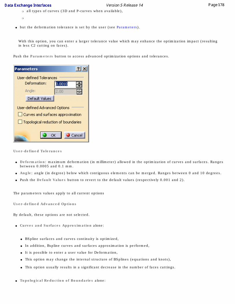
❍ all types of curves (3D and P-curves when available),
❍
● but the deformation tolerance is set by the user (see Parameters).
With this option, you can enter a larger tolerance value which may enhance the optimization impact (resulting in less C2 cutting on faces).
Push the Parameters button to access advanced optimization options and tolerances.
User-defined Tolerances
● Deformation: maximum deformation (in millimeter) allowed in the optimization of curves and surfaces. Ranges between 0.0005 and 0.1 mm.
● Angle: angle (in degree) below which contiguous elements can be merged. Ranges between 0 and 10 degrees.
● Push the Default Values button to revert to the default values (respectively 0.001 and 2).
The parameters values apply to all current options
User-defined Advanced Options
By default, these options are not selected.
● Curves and Surfaces Approximation alone:
● BSpline surfaces and curves continuity is optimized,
● In addition, Bspline curves and surfaces approximation is performed,
● It is possible to enter a user value for Deformation,
● This option may change the internal structure of BSplines (equations and knots),
● This option usually results in a significant decrease in the number of faces cuttings.
● Topological Reduction of Boundaries alone:

● BSpline surfaces and curves continuity is optimized,
● In addition, topological reduction is applied to boundaries,
● The Angle value is used to select contiguous curves that can be merged into a smooth one (tangency criteria),
● It is possible to edit the values for Deformation and Angle,❍ This combination of options usually results in a significant decrease in the number of boundary curves
(especially on poor quality input data).
● Curves and Surfaces Approximation and Topological Reduction of Boundaries together:
● BSpline surfaces and curves continuity is optimized
● In addition, BSpline curves and surfaces approximation is performed and topological reduction is applied to boundaries
● It is possible to enter user values for Deformation Tolerance and tangency Angle.
● This combination of options allows the utmost optimization of curves and surfaces, while keeping geometric deformation under control. It results in reducing the number of faces and boundaries and ensures better performance in downstream use of the data.
You can find useful information in the report file. Please see the Report file section in the IGES Import chapter in this User's Guide.
Detection of Invalidity in Input Geometry
You can choose to import IGES files with or without detecting discrepancies in geometry, by selecting the corresponding option.
Detection enables you to enter the Tolerance value above which a geometry is considered as invalid:
● size of a hole in an open boundary,
● distance between the boundary loop and the surface.
By default, the Detection option is selected.
The default Tolerance value is 3 mm.
For more information, please see the IGES Best Practices chapter in this User's Guide.

Representation for Boundaries of Faces
There are two type of IGES faces: types 144 and 143. The boundaries of those faces (respectively type 142 and 141) have two representations:
● 2D (parametric)
● 3D (spatial).
For each boundary, the IGES file contains a parameter defining the preferred representation:
● 3D,
● 2D,
● none,
● equal preference.
In the three last cases, V5 tries to import the 2D representation of the boundary. In case of failure, the 3D representation is imported.
By default, the Keep File Preference option is active:
● if the preference is set, the import will respect it.
● If no preference is set, the 2D representation is preferred.
If you do not wish to use the 2D representation (i.e. override the preference set in the IGES file), select the Force 3D representation option. Only the 3D representation will be imported.
Import Groups
By default, this option is selected and import IGES groups (Entity Type 402, Forms 1-7-14-15: Associativity Instance) as Selection Sets.
You can de-select this option for a faster import. Note that Selection Sets will not be created.
Export

Save only shown entities
● When selected, the Save only shown entities option allows you to save only the Part's entities which are in the Show mode. This is the default option. Click to clear it to export the whole model.
Curve and surface type
● The default Standard option and the BSpline option allow you to select which curve and surface types you want to be generated. If you leave the default Standard option selected the curve and surface types created in the Part are kept as is. If you select the BSpline option all curves and surfaces are converted into B-splines.
Representation mode
● If you select the default option Surface, solid decomposition will be identical in both the original model and the resulting file. Only the surfacic decomposition of the original model is stored.
● Wireframe should be used if you want 3D visualization of solid edges to be identical in both the original model and the resulting file. Only the wireframe decomposition of the original model is stored. This may be useful in cases where curves are the only form of input accepted.
● Solid-Shell lets you save Solids, Shells and Faces as IGES New Entities as follows:
V5 IGES Solid Manifold Solid B-Rep Object Entity (Type 186, Form 0) Solid (Closed) Shell Closed Shell Entity (Type 514, Form 1) Independent Shell Open Shell Entity (Type 514, Form 2) Face in a Shell Face Entity (Type 510, Form 1) Face Loop Loop Entity (Type 508, Form 1) List of Loop Edges Edge Entity (type 504, Form 1) List of Start/End Loop Edges Vertices Vertex Entity (Type 502, Form 1) Plane Surface (support of Face) Plane Surface Entity (Type 190, Form 0)
● For Loops, only the 3D Representation is exported
● All those new IGES entities have not been "tested" (IGES Norm 5.3) and the IGES/PDES Organization recommends that special consideration be given when implementing certain untested entities. Therefore if you do not know whether the receiver system will recognize those entities, we recommend that you do not use this option.

Author's Name and Organization
Enter here your name and the name of your organization.
This information will be transferred to the Global Section of the IGES file at export.
Export Units as
Let's you define the unit to be used for export. This unit can be different from the V5 file.
The default option is Keep User Unit, the IGES file unit will be :
● the unit defined in Tools -> Options -> General ->Parameters and Measure / Units tab, if the IGES Norm recognizes it,
● the Millimeter (mm) otherwise.
Units like the one named Feet, Inch, Decimal are not recognized by IGES Norm. If such Units are selected in Parameters and Measure / Units tab and if the option selected is Keep User Unit, the IGES file unit will be the Millimeter (mm).

IGES 2D
This page deals with:● Import IGES 2D options:
❍ Standards,
❍ Unit of the file,
❍ Destination view,
❍ Create end points,
❍ Convert dimensions as,
● Export IGES 2D options:❍ Exported sheets,
❍ Export mode.
Import:
Standards
Drafting:
The element you import will be placed in a Drawing, the root document of Drafting. This Drawing uses styles defined in a pre-defined or a customized standard such as ISO, JIS, ANSI, ASME. For more details about Drafting standards, please refer to Administration Tasks in the Interactive Drafting User's Guide.
Drafting Standards replace the process of the previous releases where you had to open, (eventually modify) and close a new Drawing to recover the standard you wanted to use for the data you were going to import. The standard selected in the settings is taken into account at once.
Unit of the file

By default, the option is set to Automatic and the unit of import is determined automatically (either millimeter or inch) for the best possible resulting drawing.
However, in some cases the resulting drawing is not satisfactory and requires another unit. Select this unit in the list. Then restart the import.
Destination view
Select the view in which you want to import the file.
The default Destination view is Working views.
Create end points
It is not easy to modify and stretch geometry of imported elements the way you can do it in a V5 native elements. A solution is to create end points when needed, but to the detriment of performances. Create end points offers you three options to fit your needs:
● Never: it is the default option. It ensures the best performances.
● For few entities: creates end points only for hatch boundaries and mixed polylines. This is an intermediate choice between performances and edition capabilities.
● Always: creates end points for arcs, ellipses, lines, mlines, leaders and not standard polylines and splines. Use this option only when edition capabilities are required.
Information on the option selected is given in the report file:

Convert dimensions as
If you select:
● Dimensions: linear, angular and circular dimensions will be preserved, others (ordinate types) will be transformed into details.This option keeps the semantic of the dimension. This means the position, the layout and the text are preserved. The position, color, thickness can be edited. The text of the dimension is a text that has an associative link with the dimension.This dimension has a "fake value" that is blanked.To display the true dimension value, delete the associated text and enter the data in the properties of the dimension.
Limitation for the Dimensions option: ● Linear dimensions: rotated dimensions, i.e. linear dimensions with a fixed angle other than horizontal or vertical are turned into details,
● Radial dimensions: problems may occur while positioning arrows,
● Angular dimensions, problems may occur while positioning texts,
● Following attributes are not yet supported :
● suppression of one of the dimension lines (for half dimensioning),
● offset extension or suppression of extension lines,
● arrowhead choice (the V5 default arrowhead is used).
● Geometry: geometry is exploded into multiple lines, arcs, texts. Select this option to keep the graphical aspect (this mode increase performance when loading a model).
● Details: dimensions are turned into details. This is an halfway notion between the previous two, in which the geometry is preserved and the dimension is easy to handle (it can be all selected at once).This is the default option.
Export

Exported Sheets
Select the required option to export either all sheets or only the current sheet of a multi-sheet drawing:
● The option All exports the data to several files.
The name of each file is made of the name entered in the Save as dialog box and the name of the sheet (Drawing1_sheet_1.ig2, Drawing_sheet_2.ig2, ...).
This is the default option.
● The option Only current exports the data to a file with the name entered in the Save as dialog box.
Export mode
This option offers now the choice between three export modes:
● Graphic:This was the only available mode up to Release 11. It is quick and reliable. It is useful if you want to export a CATDrawing and print it without modifying it. It is the default mode.
● Structured:This mode is introduced in Release 11. The exported file can be modified. For example, in the case of a dimension exported in Structured mode, all the graphic entities representing the dimension are exported to an Insert/Block. The more complex Drafting elements are exported the same way whereas the basic geometric elements (lines, arcs, etc) are exported as isolated elements.
● Semantic:This mode is introduced in Release 11 and is similar to the Structured mode, with the advantage that linear dimensions are exported as true dimensions (with a default dimension style). "Default dimension style" entails that most graphic attributes (such as color, display format of the dimension value, type of arrow, space...) of the dimensions are lost.
For more information, see the What About the Elements You Export? chapter.

STEP
This page deals with:● General STEP options:
❍ Detailed report,
❍ Geometric Validation Properties (GVP),
❍ Groups (Selection Sets).
● Import STEP options:❍ Continuity optimization of curves and surfaces,
❍ Assemblies physical structure,
❍ Insert existing component,
● Export STEP options:❍ Application Protocol (AP),
❍ Units,
❍ Show/NoShow,
❍ Header of the STEP file,
❍ Assemblies.
General
Detailed report
By default, the report file contains a Detailed Conversion chapter. Click to clear the Detailed Report option to remove this chapter from the report file.
Geometric Validation Properties (GVP)
This functionality is available in STEP AP214 only.
By default it is not selected.

When the Geometric Validation Properties option is selected, the Tolerances button becomes available. It opens a dialog box where you can define the tolerances for the
GVP checking.
● The first tolerance is the percentage of variation of volume or area allowed. Default value: 1%.
● The second tolerance is the maximum error for the center of gravity, expressed in mm. Default value: 1mm.
● You can retrieve the default values (1 and 1) with the Default Values button.
For import:
● Geometric validation properties are computed for each solid, shell, product or instance, and this information is written in the report file.
● For each solid, shell, product or instance, the report file gives the computed geometric validation properties:
● Centroid: coordinates of the center of gravity (applies to solid, shell, product or instance),
● Area: area of the entity (wetted area for solids) (applies to solid, shell or product),
● Volume: volume of the entity (for solids only) (applies to solid or product).
● If the imported STEP file contains geometric validation properties, these properties are read. This information is written in the report file.
● For each read geometric validation properties, the report file gives the status of comparison between read and computed properties, with the following information:
● Centroid deviation error (distance measure) (applies to solid, shell, product or instance),
● Surface area difference value and error ratio (applies to solid, shell or product),
● Volume difference value and error ratio (applies to solid or product).
● A global status for the conversion is given, together with the maximum deviations found.
Example of report file:

● The status of comparison for a given solid, shell, product or instance is ok if:
● ratios (Volume difference and Surface area difference) are lower than 1%.
● and the centroid deviation is lower than 1 mm.
● If all status are ok, the global status is ok too.
● The maximum deviation found for each comparison (centroid, area and volume) is given in the report file with the corresponding entities (the maximum deviations found do not necessarily apply to a single object).
● This functionality involves a slight performance loss, due to the properties computation cost.

For export:
● The exported STEP file includes geometric validation properties for each solid, shell, product or instance, according to STEP AP214 and the CAX-IF recommended practices.
● For each solid, shell, product or instance, the report file gives the computed geometric validation properties:
● Centroid: coordinates of the center of gravity (applies to solid, shell, product or instance),
● Area: area of the entity (wetted area for solids) (applies to solid, shell or product),
● Volume: volume of the entity (for solids only) (applies to solid or product).
● The unit used for geometric validation properties is the STEP length user unit. See Unit option.
● If the option Assemblies/Structure only is selected, the Geometric Validation Properties are not available.
● This functionality involves a slight performance loss, due to the properties computation cost.
Groups (Selection Sets)
By default, this option is selected:
● at import, Groups found in the STEP file are translated into Selection Sets.
● at export, Selection Sets found in the CATIA file are exported as Groups in the STEP file. Refer to the STEP: Export chapter for more information (Miscellaneous section).
However, importing or exporting Groups may be time consuming. Click to clear this option and de-activate the processing of Groups.
Import
Continuity optimization of curves and surfaces
By default, Automatic optimization is selected.
This setting allows a better user control over the number of curves and surfaces that are created during the process of importing STEP data into V5:

V5 requires its geometry to be C2-continuous. When non C2-continuous geometry must be imported from a STEP file, this geometry (curves, surfaces) is broken down into a set of contiguous geometries, each of them being C2-continuous. This is what happens when the No Optimization option is chosen.
However, this can produce an increase of the size of the resulting data, because more curves/surfaces are created. In order to limit this drawback, two other modes are optionally offered.
In those modes, the STEP interface tries to limit the splitting of curves and surfaces by modifying their shape slightly, so that they become C2-continuous while remaining very close to their original shape.
In order to guarantee that the deformation is not excessive, a maximum deviation parameter is used. When in Automatic optimization mode, this maximum deviation is read into the STEP file itself, in the STEP parameter that documents the precision of points in the file. In this mode, the value read from the STEP file is then corrected so that it remains comprised between 10E-2 and 10E-3. This guarantees an optimization that remains compatible with the precision for the data that was set by the emitting system.
Last, if this strategy is not enough, you can choose the Advanced optimization mode, in which an arbitrary deviation value can be entered.
You can find useful information in the report file. Please see the Report file section in the STEP Import chapter in this User's Guide.
The Automatic optimization proposes:● No approximation, thus this option does not create a significant deformation and keeps the internal BSpline structure (equations and knots).
● A continuity optimization is performed within the deformation tolerance used for optimizing BSplines, comprised between 0.001mm and 0.01mm (depending on the tolerance value defined within the imported STEP file) on:
● BSpline surfaces,
● BSpline boundary curves (3D and P-curves when available),
● BSpline independent 3D curves,
● The parameters box cannot be activated
This option softens the effect C2 cutting of faces and boundaries (which is mandatory in V5) without any significant geometric deformation
If you select No optimization:
● No optimization is performed on BSplines (neither curves nor surfaces).
● Elements are cut at discontinuity points to suit the modeler (exact mathematic continuity). This may result in a dramatic number of faces and boundary curves, data of poor quality and poor performances in further use in V5.
If you select Advanced optimization:
● No approximation. The internal BSpline structure (equations and knots) is kept,
● A continuity optimization is performed on:
● BSpline surfaces,
● BSpline boundary curves (3D and P-curves when available),
● BSpline independent 3D curves,
● but the deformation tolerance is set by the user (see Parameters).
With this option, you can enter a larger tolerance value which may enhance the optimization impact (resulting in less C2 cutting on faces).
Push the Parameters button to access advanced optimization options and tolerances.

User-defined Tolerance
● Deformation: maximum deformation (in millimeter) allowed in the optimization of curves and surfaces. Ranges between 0.005 and 0.1 mm. The default deformation is 0.003.
● Push the Default Value button to revert to the default value.
User-defined Advanced Option: Curves and surfaces approximation:
● By default, this option is not selected.
● BSpline surfaces and curves continuity is optimized,
● In addition, Bspline curves and surfaces approximation is performed,
● It is possible to enter a user value for Deformation,
● This option may change the internal structure of BSplines (equations and knots),
● This option usually results in a significant decrease in the number of faces cuttings.
Assemblies physical structure
This option enables the processing of sub-assemblies of an imported assembly.
By default, it is not selected. A CATProduct file containing the whole assembly structure and a CATPart file for each part of the assembly are created.
If you select this option, a CATProduct file containing the sub-assembly structure is created for each node of the whole assembly while a CATPart file is created for each part of the whole assembly.
STEP File One CATProduct for each product is not selected One CATProduct for each product is selected

Assembly file containing the geometry of components
1 CATProduct + N CATPart P CATProduct + N CATPart
Assembly file referencing STEP files containing the geometry of components
1 CATProduct + N CATPart
P CATProduct + N CATPart
Assembly file referencing native files containing the geometry of
components1 CATProduct + N native files
P CATProduct + N native files
Insert existing component
This option appears only if both the V5 - STEP AP203 Interface and the V5 - STEP AP214 Interface and the MULTICAx STEP Plug-in exist on the machine. By default it is not selected. Select it to activate the MultiCAD mode.
Export
Application Protocol (AP)

The default value is AP203 iso. You can switch it to AP 203 + ext or AP214 iso.
The data contained in a CATPart or CATProduct document will be saved in STEP AP203 or AP214 formats. For more information about STEP AP203, AP 203 with extensions and STEP AP214,
refer to Exporting CATPart or CATProduct Data to a STEP AP203 / AP214 File.
Units
The default value is mm (millimeter).
Select the required unit to export a CATPart or a CATProduct in STEP format and in Inch or millimeter independently of the V5 Session unit.
Show/NoShow
A CATProduct to export may contain:
● visible entities placed in the Show space,
● hidden entities placed in the NoShow space.
By default, i.e. when the option is not selected, only "Show" entities are exported.
Select the Export also NoShow entities option to export all entities belonging to both the "Show" and the "NoShow" spaces. Note that the "NoShow" entities are exported as if they were "Show" entities. This means that reading back a STEP file generated with the Export also NoShow entities option will put all the "NoShow" entities in the "Show" space.
Header of the STEP file
Push the Define... push button to define the header of the STEP file:
Fill in the form displayed as required. You can revert to the Default Values of the header by pushing the Default Values push button.

The header of the exported file looks like this:
Assemblies
Select the required option to select the export mode.
● Structure and Geometry in one file: one STEP file only containing the structure and geometry of the components. This is the option by default.
● Structure only: a STEP file containing structure and entities PRODUCT_DEFINITION_WITH_ASSOCIATED_DOCUMENT which have a link with CATPart files.
● STEP external references:
● one STEP file containing the structure
● and a STEP file for each component The STEP file names, for each component, have the same name as the components.the structure and the component STEP files are generated in one shot, in the same location.
● CATIA external references: one STEP file containing the assembly structure with external links to CATPart, CATShape, model V4, .cgr, .wrl files, according to AP 214 external

references mechanism.
The External References functionality is available only with AP214.
A STEP file cannot refer to a STEP assembly file.
This summary table shows you all the possible combinations within the first two frames, Export : Application Protocol and Export : Assemblies.
Frame Export AP ---------
Frame Export Assemblies
203 (1) 214 (2)
Structure and Geometry in one file (3) YES YES
STEP External References (4) NO (inactive button) YES
CATIA External References (4) NO (inactive button) YES
Structure only (5) YES YES
(1) = reference of the Application Protocol Config Control Design (AP203)(2) = reference of the Application Protocol Core Data for Automotive Machanical Design Processes (AP214)(3) = Export of the Structure and Geometry of a CATProduct into one file only(4) = Export of the Structure and Geometry of a CATProduct into different files(5) = Export of the Structure only of a CAProductIf you have no STEP license,you can export a CATProduct in Structure Only mode. You can choose either AP203 or AP214, but the following buttons remain inactive:
● Structure and Geometry in one file
● External References
Dynamic Licensing:
If you release the STEP license and you access the STEP options panel, the export assemblies options may change.
In this case, when you recover the STEP license, you have to go back to the STEP options panel to restore the good values.

Glossary
DDXF Autocad File Exchange format (ascii format ).
DWG Autocad File format (binary format ). Both DXF and DWG Files have the same content but under a different format.
IIGES The Initial Graphic Exchange Specification (IGES) format, is a neutral format to transfer
data between heterogeneous CAD systems.
SSTEP STEP AP203 / AP214 formats (Standard for the Exchange of Product model data)

Index
Numerics2D Export
IGES 2D IGES
Convert dimensions as
Create end points
Destination view
Export Mode
Export unit
Export VBScript Macros
Exported Sheets
Extension
Format
Import
Import VBScript Macros
Imported Elements
Multi-sheet export
Report File
Standards
Unit of the file
VBScript Macros 2D IGES VBScript Macros
utility 3D IGES
Author name and organization
Boundaries Representation
CATShape
Continuity Optimization of Curves and Surfaces
Curve and Surface Type

Detection of Invalidity in Input Geometry
Element Number
Export
Export Units as
Export VBScript Macros
Extension
General
Group Associativity
Groups
Import
Import VBScript Macros
Imported Elements
Join
Name Processing
Parameters
Product indentification
Rational B-spline Surfaces
Report File
Representation Mode
Save only shown entities
Show/NoShow Completion Dialog Box 3D IGES VBScript Macros
utility
AAdd files
Batch processing
Administration Tasks Advanced Optimization
STEP AP 214 IS

STEP Application Protocol
STEP Assemblies
STEP Assemblies physical structure
STEP Author name and organization
3D IGES
Autocad2000
BBatch monitor
Batch processing
Batch processing
Add files
Batch monitor
Delete files
Licensing Setup...
Options
Output directory
Output file
Save Batch-DXF-IGES-STEP
utility Best Practices
DXF/DWG Small Entities
Export of Large Assemblies
IGES
Import of Large Assemblies
STEP
STEP External References

STEP Quality of Conversion
STEP Topology Boundaries Representation
3D IGES
CCATCollectionStandard
Standards CATDefaultCollectionStandard
Standards CATIA external references
STEP CATShape
3D IGES CGM
Export cgm
extension CMG
insert Continuity Optimization of Curves and Surfaces
3D IGES Continuity optimization of curves and surfaces
STEP Convert Dimensions as
DXF/DWG Convert dimensions as
2D IGES Create end points
2D IGES
DXF/DWG Curve and Surface Type
3D IGES Customizing
DXF/DWG

STEP
DDelete files
Batch processing Destination view
2D IGES Detailed report
STEP Detection of Invalidity in Input Geometry
3D IGES DWG
Import DXF/DWG
Convert Dimensions as
Create end points
Customizing
Export
Export Mode
Export unit
Export VBScript Macros
Exported Sheets
Extension
Format
Import
Import of multiple viewports and layouts
Import VBScript Macros
Imported Elements
Keep Model Space
Multi-sheet export
Paper Spaces in Background
Report File

Standards
Trouble Shooting
Unit of the File
Version
What about the elements you export DXF/DWG CATIA V4
Trouble Shooting DXF/DWG File Size
Trouble Shooting DXF/DWG Kanji or unicode characters
Trouble Shooting DXF/DWG Small Entities
Best Practices DXF/DWG VBScript Macros
utility
EElement Number
3D IGES Elements imported
STRIM/STYLER Export
3D IGES
CGM
DXF/DWG
STEP
STL Export Mode
2D IGES
DXF/DWG Export of Large Assemblies
Best Practices Export unit
2D IGES

DXF/DWG Export Units as
3D IGES Export VBScript Macros
2D IGES
3D IGES
DXF/DWG
STEP Exported elements
IGES Exported Sheets
2D IGES
DXF/DWG Extension
2D IGES
3D IGES
DXF/DWG
STEP
STL extension
cgm External References
STEP
FFAQ
IGES Format
2D IGES
DXF/DWG
G

General
3D IGES Geometric Validation Properties
STEP Group Associativity
3D IGES Groups
3D IGES
STEP Groups (Selection Sets)
STEP
HHeader of the STEP file
STEP How to Create a Topology
IGES
STEP
IIGES
2D Export
Best Practices
Exported elements
FAQ
How to Create a Topology
Trouble Shooting Import
2D IGES
3D IGES
DWG
DXF/DWG

STEP
STRIM/STYLER Import of Large Assemblies
Best Practices Import of multiple viewports and layouts
DXF/DWG Import VBScript Macros
2D IGES
3D IGES
DXF/DWG
STEP Imported Elements
2D IGES
3D IGES
DXF/DWG
STEP insert
CMG Insert Existing Component
STEP Insert existing component mode
STEP
JJoin
3D IGES
KKeep Model Space
DXF/DWG

LLicensing Setup...
Batch processing Location of Standard Files
Standards
MManagement of Standards
Standard Multi-sheet export
2D IGES
DXF/DWG
NName Processing
3D IGES No optimization
STEP
OOptions
Batch processing Output directory
Batch processing Output file
Batch processing
PPaper Spaces in Background

DXF/DWG Parameters
3D IGES
STEP Part 42 Entities
STEP Product attributes
STEP Product indentification
3D IGES
RRational B-spline Surfaces
3D IGES Report File
2D IGES
3D IGES
DXF/DWG
STEP
STRIM/STYLER Representation Mode
3D IGES
SSave
Batch processing Save only shown entities
3D IGES Show/NoShow
STEP Show/NoShow Completion Dialog Box
3D IGES

Standard
Management of Standards Standards
2D IGES
CATCollectionStandard
CATDefaultCollectionStandard
DXF/DWG
Location of Standard Files STEP
Advanced Optimization
AP 214 IS
Application Protocol
Assemblies
Assemblies physical structure
Best Practices
CATIA external references
Continuity optimization of curves and surfaces
Customizing
Detailed report
Export
Export VBScript Macros
Extension
External References
Geometric Validation Properties
Groups
Groups (Selection Sets)
Header of the STEP file
How to Create a Topology
Import
Import VBScript Macros
Imported Elements
Insert Existing Component
Insert existing component mode

No optimization
Parameters
Part 42 Entities
Product attributes
Report File
Show/NoShow
STEP external references
Structure and Geometry in one file
Structure only
Trouble Shooting
Unit System
Units
User-defined Advanced Option
User-defined Tolerance
VBScript Macros STEP External References
Best Practices STEP external references
STEP STEP Quality of Conversion
Best Practices STEP specificities
Trouble Shooting STEP Topology
Best Practices STEP VBScript Macros
utility STL
Export
Extension STRIM/STYLER
Elements imported
Import
Report File

Structure and Geometry in one file
STEP Structure only
STEP Syntax errors
Trouble Shooting
TTools Options - Compatibility
VRML Tools Options - Data Exchange Interface
DXF
IGES
IGES 2D
STEP Trouble Shooting
DXF/DWG
DXF/DWG CATIA V4
DXF/DWG File Size
DXF/DWG Kanji or unicode characters
IGES
STEP
STEP specificities
Syntax errors
UUnit of the File
DXF/DWG Unit of the file
2D IGES Unit System
STEP

Units
STEP User-defined Advanced Option
STEP User-defined Tolerance
STEP utility
2D IGES VBScript Macros
3D IGES VBScript Macros
Batch-DXF-IGES-STEP
DXF/DWG VBScript Macros
STEP VBScript Macros
VVBScript Macros
2D IGES
STEP Version
DXF/DWG
WWhat about the elements you export
DXF/DWG
![Progetto-STRIM [modalità compatibilità] · Progetto STRIM STRIM è: un Sistema di visualizzazione tridimensionale stereoscopico interattivo per immagini multimodali Il progetto](https://img.dokumen.tips/doc/110x75/603ee156e940a952502ab7ed/progetto-strim-modalit-compatibilit-progetto-strim-strim-un-sistema-di.jpg)