Embed Size (px)
Citation preview

Data-Driven and Demand-Driven Computer Architecture
PHILIP C. TRELEAVEN, DAVID R. BROWNBRIDGE, AND RICHARD P. HOPKINS
Computing Laboratory, Unwerstty of Newcastle upon Tyne, Newcastle upon Tyne, NE1 7RU, England
Novel data-driven and demand-driven computer architectures are under development in a large number of laboratories in the United States, Japan, and Europe. These computers are not based on the tradlUonal von Neumann organization; instead, they are attempts to identify the next generation of computer. Basmally, m data-driven (e.g., data-flow) computers the availability of operands triggers the execution of the operation to be performed on them, whereas in demand-driven (e.g, reduction) computers the reqmrement for a result triggers the operation that will generate it.
Although there are these two distinct areas of research, each laboratory has developed its own mdlvxdual model of computation, stored program representation, and machine organization. Across this spectrum of designs there m, however, a significant sharing of concepts. The aim of this palaer m to identify the concepts and relationships that exist both within and between the two areas of research. It does thin by examlmng data-driven and demand-driven architecture at three levels, computation organizatmn, (stored) program organization, and machine organLzation. Finally, a survey of various novel computer architectures under development is given.
Categories and Subject Descriptors: C.0 [Compute r Sys t ems Organizat ion]: General-- hardware/software interfaces; system architectures; C.1.2 [P rocesso r Archi tec ture] : Multiple Data Stream Architectures (Multiprocessors); C.1.3 [P rocesso r Arch i tec ture ] Other Architecture Styles--data-flow architectures; high-level language architectures, D 3 2 [ P r o g r a m m i n g Languages] Language Classifications--data-flow languages; macro and assembly languages; very hzgh-level languages
General Terms: Design
Add~tmnal Key Words and Phrases Demand = driven architecture, data - driven architecture
INTRODUCTION
For more than thirty years the principles of computer architecture design have largely remained static [ORGA79], based on the von Neumann organization. These von Neu- mann principles include
(1) a single computing element incorporat- ing processor, communications, and memory;
(2) hnear organization of fLxed-size mem- ory cells;
(3) one-level address space of cells; (4) low-level machine language (instruc-
tions perform simple operations on el- ementary operands);
(5) sequential, centralized control of com- putation.
Over the last few years, however, a num- ber of novel computer architectures based on new "naturally" parallel organizations for computation have been proposed and some computers have even been built. The principal stimuli for these novel architec- tures have come from the pioneering work on data flow by Jack Dennis [DENN74a, DENS74b], and on reduction languages and machines by John Backus [BACK72, BACK73] and Klaus Berkling [BERK71, BERK75]. The resulting computer architec- ture research can be broadly classified as either data driven or demand driven. In data-driven (e.g., data-flow) computers the availability of operands triggers the execu- tion of the operation to be performed on them, whereas in demand-driven (e.g., re-
Permission to copy without fee all or part of this material m granted provided that the copies are not made or distributed for direct commercial advantage, the ACM copyright notice and the title of the publication and its date appear, and notice is gwen that copying m by permission of the Association for Computing Machinery. To copy otherwise, or to republish, requires a fee and/or specific permission. © 1982 ACM 0010-4892/82/0300-0093 $00.75
Computing Surveys, Vol. 14, No 1, March 1982
94 * P. C. Treleaven, D. R. Brownbridge, and R. P. Hopkins
CONTENTS
I N T R O D U C T I O N I BASIC C O N C E P T S
1 1 Control Flow 1 2 Da ta Flow 1 3 Reduct ion
2. C O M P U T A T I O N ORGANIZATION 2 1 Classification 2 2 Control Flow 2 3 Da ta Flow 2 4 Reduc tmn 2 5 Implications
3 P R O G R A M ORGANIZATION 3.1 Classification 3 2 Control Flow 3 3 Da ta Flow 3 4 Reduct ion 3 5 Imphcat ions
4 M A C H I N E ORGANIZATION 4 1 Classification 4 2 Control Flow 4 3 D a t a Flow 4.4 Reductmn 4 5 Implications
5 DATA-FLOW C O M P U T E R S 5 1 M I.T Data-Flow Computer 5 2 Texas Ins t ruments Distr ibuted Da ta Processor 5 3 U tah Data-Dr iven Machine (DDM1) 5 4 Irvme Data-Flow Machine 5 5 Manches ter Data-Flow Computer 5 6 Toulouse LAU System 5 7 Newcastle Data-Control Flow Computer 5.8 Other Projects
6 R E D U C T I O N C O M P U T E R S 6 1 G M D Reduct ion Machine 6 2 Newcastle Reduct ion Machine 6 3 N o r t h Carohna Cellular Tree Machine 6 4 U tah Applicative Mult lprocessmg Sys tem 6.5 S - K Reduct ion Machine 6 6 Cambridge SKIM Machine 6.7 Other Projects
7 F U T U R E DIRECTIONS A C K N O W L E D G M E N T S R E F E R E N C E S BIBLIOGRAPHY
A
v
duction) computers the requirement for a result triggers the operation that will gen- erate it.
Although the motivations and emphasis of individual research groups vary, there are basically three interacting driving forces. First, there is the desire to utilize concurrency to increase computer perform-
ance. This is based on the continuing de- mand from areas such as weather forecast- ing and wind tunnel simulation for com- puters with a higher performance. The nat- ural physical laws place fundamental limi- tations on the performance increases ob- tainable from advances in technology alone. And conventional high-speed computers like CRAY 1 and ILLIAC IV seem unable to meet these demands [TREL79]. Second, there is the desire to exploit very large scale integration (VLSI) in the design of com- puters [SEIT79, MEAD80, TREL80b]. One effective means of employing VLSI would be parallel architectures composed of iden- tical computing elements, each containing integral capabilities for processing, com- munication, and memory. Unfortunately "general-purpose" organizations for inter- connecting and programming such archi- tectures based on the von Neumann prin- ciples have not been forthcoming. Third, there is the growing interest in new classes of very high level programming languages. The most well-developed such class of lan- guages comprises the functional languages such as LISP [McCA62], FP [BACK78], LUCID [ASHC77], SASL [TURN79a], Id [ARvI78], and VAL [ACKE79b]. Because of the mismatch between the various princi- ples on which these languages are based, and those of the von Neumann computer, conventional implementations tend to be inefficient.
There is growing agreement, particularly in Japan and the United Kingdom, that the next generation of computers will be based on non-von Neumann architecture. (A re- port [JIPD81a] by Japan's Ministry of In- ternational Trade and Industry contains a good summary of the criteria for these fifth- generation computers.) Both data-driven and demand-driven computer architecture are possible fifth-generation architectures. The question then becomes, which archi- tectural principles and features from the various research projects will contribute to this new generation of computers?
Work on data-driven and demand-driven architecture falls into two principal re- search areas, namely, data flow [DENN79b, Gosw79a] and reduction [BERK75]. These areas are distinguished by the way compu- tation, stored programs, and machine re-
Comput ing Surveys, Vol 14, No. 1, March 1982
Data-Driven and Demand-Driven Computer Architecture • 95
sources are organized. Although research groups in each area share a basic set of concepts, each group has augmented the concepts often by introducing ideas from other areas {including traditional control- flow architectures) to overcome difficulties. The aim of this paper is to identify the concepts and relationships that exist both within and between these areas of research. We start by presenting simple operational models for control flow, data flow, and re- duction. Next we classify and analyze the way computation, stored programs, and machine resources are organized across the three groups. Finally, a survey of various novel computer architectures under devel- opment is given in terms of these classifi- cations.
1. BASIC CONCEPTS
Here we present simple operational models of control flow, data flow, and reduction. In order to compare these three models we discuss each in terms of a simple machine code representation. These representations are viewed as instructions consisting of se- quences of arguments--operators, literal operands, references--dehmited by paren- theses:
(argO argl arg2 arg3 . . . a r g n - 1 argn).
However, the terms "instruction" and "ref- erence" are given a considerably more gen- eral meaning than their counterparts in conventional computers. To facilitate com- parisons of control flow, data flow, and re- duction, simple program representations for the statement a = (b + 1) • (b - c) are used. Although this statement consists of simple operators and operands, the con- cepts illustrated are equally applicable to more complex operations and data struc- tures.
1.1 Control Flow
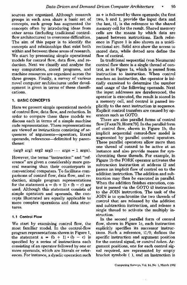
We start by examining control flow, the most familiar model. In the control-flow program representations shown in Figure 1, the statement a = (b + 1)*(b - c) is specified by a series of instructions each consisting of an operator followed by one or more operands, which are literals or refer- ences. For instance, a dyadic operation such
as + is followed by three operands; the f'~rst two, b and 1, provide the input data and the last, t l , is the reference to the shared memory cell for the result. Shared memory cells are the means by which data are passed between instructions. Each refer- ence in Figure 1 is also shown as a unidi- rectional arc. Solid arcs show the access to stored data, while dotted arcs define the flow of control.
In traditional sequential (von Neumann) control flow there is a single thread of con- trol, as in Figure la, which is passed from instruction to instruction. When control reaches an instruction, the operator is ini- tially examined to determine the number and usage of the following operands. Next the input addresses are dereferenced, the operator is executed, the result is stored in a memory cell, and control is passed im- plicitly to the next instruction in sequence. Explicit control transfers are caused by op- erators such as GOTO.
There are also parallel forms of control flow [FARR79, HOPK79]. In the parallel form of control flow, shown in Figure lb, the implicit sequential control-flow model is augmented by parallel control operators. These parallel operators allow more than one thread of control to be active at an instance and also provide means for syn- chronizing these threads. For example, in Figure lb the FORK operator activates the subtraction instruction at address i2 and passes an implicit flow of control on to the addition instruction. The addition and sub- traction may then be executed in parallel. When the addition finishes execution, con- trol is passed via the GOTO i3 instruction to the JOIN instruction. The task of the JOIN is to synchronize the two threads of control that are released by the addition and subtraction instruction, and release a single thread to activate the multiply in- struction.
In the second parallel form of control flow, shown in Figure lc, each instruction explicitly specifies its successor instruc- tions. Such a reference, il/0, defines the specific instruction and argument position for the control signal, or control token. Ar- gument positions, one for each control sig- nal required, are represented by empty bracket symbols ( ) , and an instruction is
Computing Surveys, Vol. 14, No 1, March 1982
96 • P.C. Treleaven, D. R. Brownbridge, and R. P. Hopkins
( ) t 2 : ( ) a : ( )
..~)
(a)
s-- -~ i2:~--- -~i3: (...FORK i2 ~ + b 1 tl GOTO i3 ~- b c t2 JOIN 2 * tl t2 a
b:(4 : tl:( ) t2:( ) a:( )
(b)
. , . )
t0: ( . . . il/o 12/o) bj,(4)¢,__ ¢: (2) ; . . . . . \
i l : ( ( l~) + b 1 t l i 3 / 0 ) t 2 : ( ( 4 ) - b c
i t
- " " t 2 : ( ) I t l : ( ) /
t3: ((~') (I,) t l t2 a . . . )
a : ( )
(c)
t 2 i 3 / i )
Figure 1. Control~flow programs for a = (b + 1) * (b - c): (a) sequential, (b) parallel "FORK-JOIN" ; (c) parallel "control tokens."
executed when it has received the required control tokens. The two parallel forms of control flow, illustrated by Figures lb and lc, are semantically equivalent; FORKS are equivalent to multiple successor instruction addresses and JOINs are equivalent to mul- tiple empty bracket arguments.
The sequential and parallel control-flow models have a number of common features: (1) data are passed indirectly between in- structions via references t~ shared memory cells; (2) literals may be stored in instruc- tions, which can be viewed as an optimiza- tion of using a reference to access the literal; (3) flow of control is implicitly sequential, but explicit control operators can be used for parallelism, etc.; and (4) because the flows of data and control are separate, they can be made identical or distinct.
1.2 Data Flow
Data flow is very similar to the second form of parallel control flow with instructions
Computing Surveys, Vol. 14, No 1, March 1982
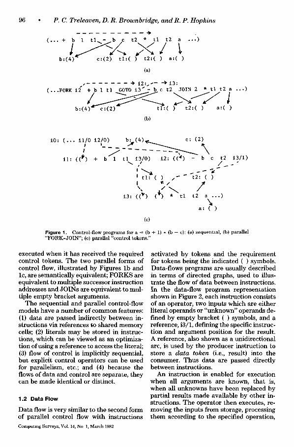
activated by tokens and the requirement for tokens being the indicated ( ) symbols. Data-flows programs are usually described in terms of directed graphs, used to illus- trate the flow of data between instructions. In the data-flow program representation shown in Figure 2, each instruction consists of an operator, two inputs which are either literal operands or "unknown" operands de- fined by empty bracket ( ) symbols, and a reference, i3/1, defining the specific instruc- tion and argument position for the result. A reference, also shown as a unidirectional arc, is used by the producer instruction to store a data token (i.e., result) into the consumer. Thus data are passed directly between instructions.
An instruction is enabled for execution when all arguments are known, that is, when all unknowns have been replaced by partial results made available by other in- structions. The operator then executes, re- moving the inputs from storage, processing them according to the specified operation,
Data-Driven and Demand-Driven Computer Architecture
14 i 1 13: ) ( )~ a/l)
(a)
97
! !
11: (+ (~) 1 13/1) 12: (-
13: (*~()
(~) (I) i3 /2)
)
(b) 10
Figure 2. D a t a - f l o w p r o g r a m for a = (b + 1) * (b - c) (a) S t a g e 1; (b) S t a g e 4.
and using the embedded reference to store the result a t an unknown operand in a successor instruction. In t e rms of directed graphs, an instruct ion is enabled when a da ta token is present on each of its input arcs. During execution the opera tor re- moves one da ta token f rom each input arc and releases a set of result tokens onto the output arcs.
Figure 2 i l lustrates the sequence of exe- cution for the p rogram f ragment a = (b + 1) * (b - c), using a black dot on an arc to indicate the presence of a da ta token. The two black dots at Stage 1 in Figure 2 indi- cate tha t the data tokens corresponding to the values of b and c have been genera ted by predecessor instructions. Since b is re- quired as input for two subsequent instruc- tions, two copies of the token are genera ted and stored into the respective locations in each instruction. T h e availabili ty of these inputs completes bo th the addit ion and the subtract ion instruction, and enables their operators for execution. Executing com- pletely independently, each opera tor con- sumes its input tokens and stores its result
into the mult ipl icat ion instruct ion "i3." This enables the multiplication, which ex- ecutes and stores its result corresponding to the identifier "a," shown at Stage 4.
In the data-flow model there are a num- ber of interesting features: (1) par t ia l re- sults are passed directly as da ta tokens between instructions; (2) literals m a y be embedded in an instruction tha t can be viewed as an optimizat ion of the data token mechanism; (3) execution uses up da ta to- k e n s m t h e values are no longer available as inputs to this or any o ther instruction; (4) there is no concept of shared da ta s torage as embodied in the t radi t ional notion of a variable; and (5) sequencing cons t ra in t s - - flows of con t ro l - - a re t ied to the flow of data.
1.3 Reduction
Control-flow and data-flow programs are built f rom fixed-size instructions whose ar- guments are primit ive opera tors and oper- ands. Higher level p rogram st ructures are built f rom linear sequences of these primi- t ive instructions.
Computing Surveys, Vol. 14, No 1, March 1982
98 ° P. C. Treleaven, D. R. Brownbridge, and R. P. Hopkins
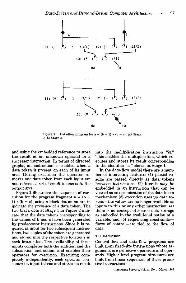
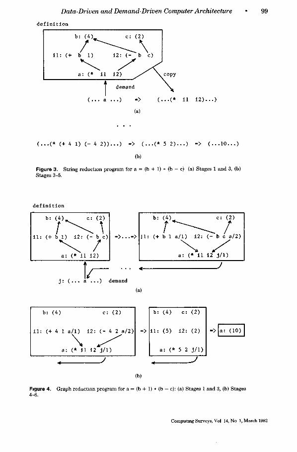
In contrast, reduction programs are built from nested expressions. The nearest anal- ogy to an "instruction" in reduction is a function application, consisting of (func- tion) (argument), which returns its result in place. Here a (function) or (argument) is recursively defined to be either an atom, such as + or 1, or an expression. Likewise, a reference may access, and function appli- cation may return, either an atom or an expression. Higher level program structures are reflected in this machine representa- tion, being themselves function applica- tions built from more primitive functions. In reduction, a program is mathematically equivalent to its result in the same way that the expression 3 + 3 is equivalent to the number 6. Demanding the result of the definition "a," where a -- (b + 1) * (b - c), means that the embedded reference to "a" is to be rewritten in a simpler form. (It may be helpful for the reader to view this eval- uation of a reference as calling the corre- sponding definition, giving reduction a CALL-RETURN pattern of control.) Be- cause of these attributes, only one defini- tion of "a" may occur in a program, and all references to it give the same value, a prop- erty known as referential transparency. There are two forms of reduction, differ- entiated in the way that arguments in a program are manipulated, called string re- duction and graph reduction.
The basis of string reduction is that each instruction that accesses a particular defi- nition will take and manipulate a separate copy of the definition. Figure 3 illustrates string manipulation for a reduction execu- tion sequence involving the definition a -- (b + 1) • (b - c). Each instruction consists of an operator followed by literals or embedded references, which are used to demand its input operands. At Stage 1 in Figure 3 some instruction, containing the reference "a," demands the value corre- sponding to the definition "a." This causes a copy of the definition to be loaded into the instruction overwriting the reference "a," as also shown in Figure 3. Next the multiplication operator demands the values corresponding to i l and i2, causing them to be overwritten by copies of their defini- tions. The multiplication then suspends and the addition and subtraction operators de-
mand the values of b and c. The substitu- tion of the values 4 and 2 is shown at Stage 3 in Figure 3. The reducible subexpressions (+ 4 1) and ( - 4 2) are then rewritten, caus- ing the multiplication to be reenabled. Fi- nally at Stage 5 the multiplication is re- placed by the constant 10, which is the value of "a."
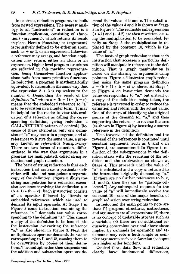
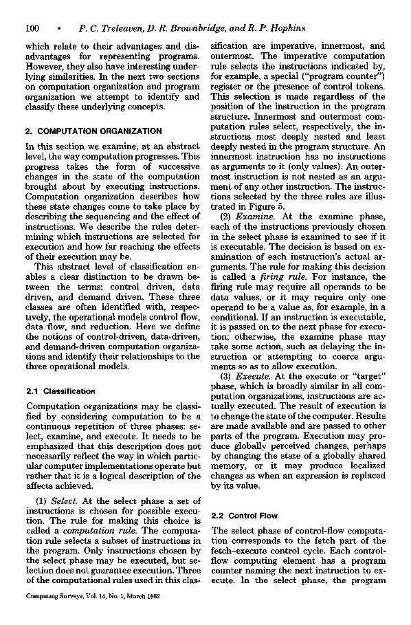
The basis of graph reduction is that each instruction that accesses a particular defi- nition will manipulate references to the def- inition. That is, graph manipulation is based on the sharing of arguments using pointers. Figure 4 illustrates graph reduc- tion using the same program definition a -- (b + 1) * (b - c) as above. At Stage 1 in Figure 4 an instruction demands the value corresponding to "a," but instead of a copy of the definition being taken, the reference is traversed in order to reduce the definition and return with the actual value. One of the ways of identifying the original source of the demand for "a," and thus supporting the return, is to reverse the arcs (as shown in Figure 4) by inserting a source reference in the definition.
This traversal of the definition and the reversal of the references is continued until constant arguments, such as b and c in Figure 4, are encountered. In Figure 4, re- duction of the subexpressions in the defi- nition starts with the rewriting of the ad- dition and the subtraction as shown at Stage 4. This proceeds until the value of "a" is calculated and a copy is returned to the instruction originally demanding "a." (If there are no further references to b, c, il, and i2, then they can be "garbage col- lected.") Any subsequent requests for the value of "a" will immediately receive the constant 10--one of the major benefits of graph reduction over string reduction.
In reduction the main points to note are that: (1) program structures, instructions, and arguments are all expressions; (2) there is no concept of updatable storage such as a variable; (3) there are no additional se- quencing constraints over and above those implied by demands for operands; and (4) demands may return both simple or com- plex arguments such as a function (as input to a higher order function).
Control flow, data flow, and reduction clearly have fundamental differences,
Computing Surveys, Vol. 14, No 1, March 1982
Data-Driven a n d Demand-Dr iven Computer Arch i tec ture • 99
definition
il: (+
7 a : (* t l t 2 ) ~ ~ c o p y
" N I demand
(... a ...) => ( . . . ( *
(a)
ll i2)...)
(...(* (+ 4 i) (- 4 2))...) => (...(* 5 2)...) => (...i0...)
(b)
Figure 3. String reductlon program for a = (b + l) * (b - c) (a) Stages 1 and 3, (b) Stages 3-5.
definition
il: (+ b ~ : (-?e)
a: (* il 12)
= > . . . =>
° , .
j: (... a ...) demand
i l : (+ b 1 a / l ) i 2 : ( - b / 2 )
J a: (* II i2 j/l)
Y
(a)
b: (4) c: (2)
il: (+ 4 1 a/l) 12: (- 4 2 a/2)
a: (* ii 12 j/l)
=>
b: (4) c: (2)
i l : (5 ) i 2 : (2 )
a : (* 5 2 j / l )
, . ) . J
=>Ja: (10) J
(b)
Figure 4. Graph reduction program for a = (b + 1) * (b - c): (a) Stages 1 and 3, (b) Stages 4-6.
Computing Surveys, Vol 14, No 1, March 1982
100 • P.C. Treleaven, D. R. Brownbridge, and R. P. Hopkins
which relate to their advantages and dis- advantages for representing programs. However, they also have interesting under- lying similarities. In the next two sections on computation organization and program organization we attempt to identify and classify these underlying concepts.
2. COMPUTATION ORGANIZATION
In this section we examine, at an abstract level, the way computation progresses. This progress takes the form of successive changes in the state of the computation brought about by executing instructions. Computation organization describes how these state changes come to take place by describing the sequencing and the effect of instructions. We describe the rules deter- mining which instructions are selected for execution and how far reaching the effects of their execution may be.
This abstract level of classification en- ables a clear distinction to be drawn be- tween the terms: control driven, data driven, and demand driven. These three classes are often identified with, respec- tively, the operational models control flow, data flow, and reduction. Here we define the notions of control-driven, data-driven, and demand-driven computation organiza- tions and identify their relationships to the three operational models.
2.1 Classification
Computation organizations may be classi- fied by considering computation to be a continuous repetition of three phases: se- lect, examine, and execute. It needs to be emphasized that this description does not necessarily reflect the way in which partic- ular computer implementations operate but rather that it is a logical description of the affects achieved.
(1) Select. At the select phase a set of instructions is chosen for possible execu- tion. The rule for making this choice is called a computation rule. The computa- tion rule selects a subset of instructions in the program. Only instructions chosen by the select phase may be executed, but se- lection does not guarantee execution. Three of the computational rules used in this clas-
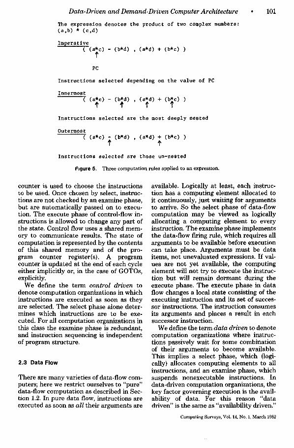
sification are imperative, innermost, and outermost. The imperative computation rule selects the instructions indicated by, for example, a special ("program counter") register or the presence of control tokens. This selection is made regardless of the position of the instruction in the program structure. Innermost and outermost com- putation rules select, respectively, the in- structions most deeply nested and least deeply nested in the program structure. An innermost instruction has no instructions as arguments to it (only values). An outer- most instruction is not nested as an argu- ment of any other instruction. The instruc- tions selected by the three rules are illus- trated in Figure 5.
(2) Examine. At the examine phase, each of the instructions previously chosen in the select phase is examined to see if it is executable. The decision is based on ex- amination of each instruction's actual ar- guments. The rule for making this decision is called a firing rule. For instance, the firing rule may require all operands to be data values, or it may require only one operand to be a value as, for example, in a conditional. If an instruction is executable, it is passed on to the next phase for execu- tion; otherwise, the examine phase may take some action, such as delaying the in- struction or attempting to coerce argu- ments so as to allow execution.
(3) Execute. At the execute or "target" phase, which is broadly similar in all com- putation organizations, instructions are ac- tually executed. The result of execution is to change the state of the computer. Results are made available and are passed to other parts of the program. Execution may pro- duce globally perceived changes, perhaps by changing the state of a globally shared memory, or it may produce localized changes as when an expression is replaced by its value.
2.2 Control Flow
The select phase of control-flow computa- tion corresponds to the fetch part of the fetch-execute control cycle. Each control- flow computing element has a program counter naming the next instruction to ex- ecute. In the select phase, the program
Computing Surveys, Vol. 14, No. 1, March 1982
Data-Driven and Demand-Driven Computer Architecture
The e x p r e s s i o n d e n o t e s t h e p r o d u c t o f two complex number s : ( a , b ) * ( c , d )
101
Imperatlve ( ( a ' c ) - (b~d) , ( a ' d ) + ( b ~ c ) )
?
PC
Instructions selected depending on the value o f PC
Innermost
Instructions selected are the most deeply nested
Outermost ( (a-c) r (b'd) , (a'd) + (b~c))
Instructions selected are those un-nested
Figure 5. Three computation rules applied to an expression.
counter is used to choose the instructions to be used. Once chosen by select, instruc- tions are not checked by an examine phase, but are automatically passed on to execu- tion. The execute phase of control-flow in- structions is allowed to change any part of the state. Control flow uses a shared mem- ory to communicate results. The state of computation is represented by the contents of this shared memory and of the pro- gram counter register(s). A program counter is updated at the end of each cycle either implicitly or, in the case of GOTOs, explicitly.
We define the term control driven to denote computation organizations in which instructions are executed as soon as they are selected. The select phase alone deter- mines which instructions are to be exe- cuted. For all computation organizations in this class the examine phase is redundant, and instruction sequencing is independent of program structure.
2.3 Data Flow
There are many varieties of data-flow com- puters; here we restrict ourselves to "pure" data-flow computation as described in Sec- tion 1.2. In pure data flow, instructions are executed as soon as all their arguments are
available. Logically at least, each instruc- tion has a computing element allocated to it continuously, just waiting for arguments to arrive. So the select phase of data-flow computation may be viewed as logically allocating a computing element to every instruction. The examine phase implements the data-flow firing rule, which requires all arguments to be available before execution can take place. Arguments must be data items, not unevaluated expressions. If val- ues are not yet available, the computing element will not try to execute the instruc- tion but will remain dormant during the execute phase. The execute phase in data flow changes a local state consisting of the executing instruction and its set of succes- sor instructions. The instruction consumes its arguments and places a result in each successor instruction.
We define the term data driven to denote computation organizations where instruc- tions passively wait for some combination of their arguments to become available. This implies a select phase, which (logi- cally) allocates computing elements to all instructions, and an examine phase, which suspends nonexecutable instructions. In data-driven computation organizations, the key factor governing execution is the avail- ability of data. For this reason "data driven" is the same as "availability driven."
Computing Surveys, Vol. 14, No. 1, March 1982
102
2.4 Reduction
Reduction computers each have different rules embodied in their select phase. The choice of computation rule is a design choice for a particular reduction computer. The commonest rules used are innermost and outermost (see Figure 5), and in fact the discussion of reduction in Section 1 was restricted to outermost reduction. The computation rule in a reduction computer determines the allocation of computing ele- ments at the beginning of each computation cycle. In the examine phase the arguments are examined to see whether execution is possible. If it is, the instruction is executed. Otherwise, the computing element tries to coerce the arguments into the required pat- tern. This coercion demands the evaluation of argument(s) until sufficient are available for execution. Logically, this demand con- sists of spawning one or more subcompu- tations to evaluate operands and waiting for them to return with a value. The in- struction set of a reduction computer may contain many different firing rules, each instruction having the rule most suited to it. For example, all arithmetic operations will have a firing rule that forces their ar- guments to be values. The execute phase in a reduction machine involves rewriting an instruction in situ. The instruction is re- placed by its result where it stands. Only the local state consisting of the instruction itself and those instructions that use its results are changed. Execution may thus also enable another instruction.
We define the term demand driven to denote a computation organization where instructions are only selected when the value they produce is needed by another, already selected instruction. All outermost reduction architectures fall into this cate- gory but innermost reduction architectures do not. The essence of a demand-driven computation organization is that an in- struction is executed only when its result is demanded by some other instruction and the arguments may be recursively evalu- ated where necessary. In reduction com- puters with an innermost computation rule, instructions are never chosen by select until their arguments are available. This restric- tion means that all arguments reaching the
• P.C. Treleaven, D. R. Brownbrtdge, and R. P. Hopkins
examine stage are preevaluated and hence no coercions need ever take place. It also means that all instructions have all their arguments evaluated whether or not this is necessary, exactly as occurs in data flow. Thus we believe innermost computation organizations are data driven.
2.5 Implications
The implications of the computation orga- nization classification can now be summa- rized. Control-flow computers have a con- trol-driven computation organization; in- structions are arbitrarily selected, and once selected they are immediately executed. Data-flow computers have a data-driven computation organization; all instructions are in principle active, but only execute when their arguments become available. Some reduction computers are demand driven and some are data driven.
Control-flow computers all have a con- trol-driven computation organization. The control-driven organization is characterized by the lack of an examine stage, and by a computation rule that selects instructions independently of their place in the pro- gram's structure. This implies that the pro- gram has complete control over instruction sequencing. Once selected, instructions will always be executed regardless of the state of their operands. There is no wait for ar- guments, or demand for arguments, apart from the dereferencing of an address. It is up to the programmer to ensure that argu- ments are set up before control reaches an instruction. The advantage of control- driven computation is full control over se- quencing. The corresponding disadvantage is the programming discipline needed to avoid run-time errors. These errors are harder to prevent and detect than excep- tions (overflow, etc.), which occur at the execute phase in all computation organiza- tions. A typical example of the twin gener- alities and dangers of control-driven com- putation organization is the ability to exe- cute data as a program.
Data-flow computers have a data-driven computation organization that is character- ized by a passive examine stage. Instruc- tions are examined, and if they do not pass the firing rule, no action is taken to force
Computing Surveys, Vol 14, No 1, March 1982
Data-Driven and Demand-Driven Computer Architecture
them to become executable. The data-flow firing rule requires all arguments to arrive before an instruction will execute. However, some data-flow implementations have found this too restrictive and have added non-data-driven instructions to provide some degree of explicit control. The advan- tage of data-driven computation is that in- structions are executed as soon as their arguments are available, giving a high de- gree of implicit parallelism. The disadvan- tages are that instructions may waste time waiting for unneeded arguments. This be- comes increasingly apparent when the im- plementation of data-flow procedures is considered. In addition, operators such as an if-then-else operator, which will use only two of its three arguments, discarding the other, will always be forced to wait for all three. In the worst case this can lead to nontermination through waiting for an un- needed argument, which is, for example, an infinite iteration.
A reduction computer having a demand- driven organization is characterized by an outermost computation rule coupled with the ability to coerce arguments at the ex- amine stage. Instruction sequencing is driven by the need to produce a result at the outermost level, rather than to insist on following a set pattern. Each instruction chosen by the outermost select can decide to demand further instructions. Instruc- tions actively coerce their arguments to the required form if they are not already in it. Reduction computers not possessing (1) an outermost select and (2) a coercing examine phase cannot be classified as demand driven. The advantage of the demand- driven computation organization is that only instructions whose result is needed are executed. A procedure-calling mechanism is built in, by allowing the operator of an instruction to be defined as a block of in- structions. The disadvantage of demand- driven computation is in processing, say, arithmetic expressions, where every in- struction (+, *, etc.) always contributes to the final result. Propagating demand from outermost to innermost is wasted effort; only operator precedence will determine sequencing, and every instruction must be activated. In these cases, data-driven com- putation organization is better since the
• 103
sequencing is determined solely by operator priorities. Demand driven is superior only for "nonstrict" operators such as "if-then- else," which do not require all their argu- ments.
Last, the execute phase of any computa- tion organization has important conse- quences for the underlying implementation. Global changes may have far-reaching ef- fects, visible throughout the computer. Lo- cal changes can only alter the state of a small part of the computation. To support a computation organization allowing global state changes, some form of global com- munications between instructions is re- quired. On the other hand, if only local changes are to be supported, this locality can be exploited in a distributed architec- ture. In general, data-flow and reduction programs are free from side effects, another feature making them suitable for distrib- uted implementation.
3. PROGRAM ORGANIZATION
We use the term program organization to cover the way machine code programs are represented and executed in a computer architecture. This section starts by classi- fying the underlying mechanisms of pro- gram organization for control-flow, data- flow, and reduction models.
3.1 Classification
Two computational mechanisms, which we refer to as the data mechanism and the control mechanism, seem fundamental to these three groups of models. The data mechanism defines the way a particular argument is used by a number of instruc- tions. There are three subclasses:
(1) by hteral--where an argument is known at compile time and a separate copy is placed in each accessing instruc- tion {found in all the operational models);
(2) by value--where an argument, gener- ated at run time, is shared by replicat- ing it and giving a separate copy to each accessing instruction, this copy being stored as a value in the instruction (as seen in data flow and string reduction};
Computing Surveys, VoL 14, No. 1, March 1982
104 P. C. Treleaven, D. R. Brownbridge, and R. P. Hopkins
Data Mechanisms
by va lue by r e f e r e n c e (& literal) (& literal)
Control
Mechanisms
sequential
parallel
recurslve
yon Neumann control flow
parallel data flow control flow
string graph reduction reduction
Figure 6. Computational models: control and data mechamsms.
(3) by reference--where an argument is shared by having a reference to it stored in each accessing instruction (as seen in control flow and graph reduction).
The control mechanism defines how one instruction causes the execution of another instruction, and thus the pattern of control within the total program. There are again three subclasses:
(1) sequential--where a single thread of control signals an instruction to execute and passes from one instruction to an- other (as seen in traditional sequential control flow);
(2) parallel--where control signals the availability of arguments and an in- struction is executed when all its argu- ments (e.g., input data) are available (as seen in data flow and parallel con- trol flow);
(3) recursive--where control signals the need for arguments and an instruction is executed when one of the output arguments it generates is required by the invoking instruction. Having exe- cuted, it returns control to the invoking instruction (as seen in string reduction and graph reduction).
The relationship of these data and con- trol mechanisms to the three groups of op- erational model is summarized in Figure 6. Using this classification as a basis, we now examine the advantages and disadvantages for program representation and execution of control flow, data flow, and reduction.
3.2 Control Flow
Control flow is based on a "sequential" or "parallel" control mechanism. Flow of con- trol is implicitly sequential with explicit sequential and parallel patterns of control being obtained from, respectively, GOTO and FORK-JOIN style control operators. The basic data mechanism of control flow is a by-reference mechanism, with refer- ences embedded in instructions being used to access shared memory cells. This form of data sharing is shared update, in which the effects of changing the contents of a memory cell are immediately available to other users.
In computers based on parallel program organizations such as parallel control flow, special precautions must be taken in a pro- gram's representation (style of machine code generated) to ensure that the natural asynchronous execution does not lead to unwanted indeterminacy. This is basically a problem of synchronizing the usage of shared resources, such as a memory cell containing an instruction or data. It is ap- propriate to examine the support in parallel control-flow computers of two important programming mechanisms--iteration and procedures--because they illustrate how these synchronization problems are con- trolled and also the style of program rep- resentation used.
Iteration becomes a potential problem for parallel control flow because program fragments with loops may lead to logically cyclic graphs in which each successive it-
Computing Surveys, Vol. 14, No. I, March 1982
Data-Driven and Demand-Dr iven Computer Arch i tec ture • 105
I I I I I I
I
(fl'f2):= 1 (1,1)
-- - _>_-"~ . . ..~_~ -- --.
I ~k
true IIF i > i00 J l I
' false I +
!
| ~ , ~
I answer : - I I I ( f l , f 2 ) : = f2 I',l (f2,fl+f2)[
' I J q,
I
F i g u r e 7. Control-flow i terat ion us ing feedback.
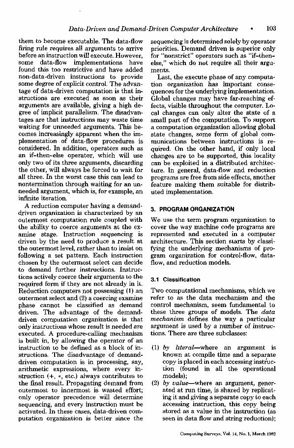
erat ion of a loop could execute concur- rently, giving the possibility, for instance, of mul t ip le-data i tems being stored in the same m e m o r y cell. Two possible schemes may, in general, be used to control poten- tially concurrent iteration. The first uses the feedback of control to synchronize ref- erence usage and the second represents it- erat ion by the equivalent recursion, thereby creating unique contexts for references.
To il lustrate these two schemes for rep- resenting iteration, we use as an example a p rogram f ragment tha t calculates the one- hundred th number in the Fibonacci series:
(fl, f2) := (1, 1); FORi = 3 TO 100 DO
(fl, f2) := (f2, f l + f2) OD; answer := f2;
This fragment , using concurrent assign- ment , consists of two calculations, one pro- ducing the Fibonacci series as successive values of f2, and the other increment ing the i teration count i. Since i is not used within the D O . . . OD, these two calculations m a y execute in parallel.
The first scheme for support ing i terat ion based on the feedback of control to syn- chronize resource usage is shown in Figure 7. This ensures tha t only a single copy of an instruction can be active or tha t a single data i tem m a y occupy a m e m o r y cell, at an instant. This synchronizat ion is achieved
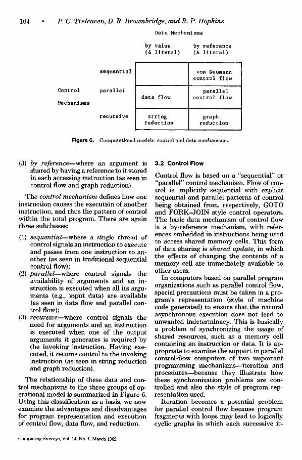
by the J O I N instruction. Next the IF in- struction, if false, per forms a new i terat ion or, if true, t ransfers the value of f2 to m e m - ory cell "answer." Since m e m o r y cells are continually upda ted in this i terat ion scheme, it m a y be necessary in specific implementa t ions to execute the concurrent ass ignment (fl , f2) := (f2, f l + f2) sequen- tially to exclude indeterminacy. T h e second i terat ion scheme makes use of the proce- dure mechan i sm to provide separa te con- texts for each iteration, by t ransforming the i terat ive p rogram into the equivalent recur- sion:
fib(f1, f2, i) := IF i > 100 THEN f2 ELSE fib(f2, f l + f2, i + 1) FI;
answer := fib(l, 1, 3);
Each t ime a new call of the function fib is made, a new process, with a separa te con- text, is created.
At a logical level there are two instruc- tions involved in procedure invocation. (Figure 8 i l lustrates this procedure mecha- nism.) In a calling process P1, there is a CALL instruct ion tha t first obtains a new (globally unique) process identifier P2 and then changes the context of the input pa- ramete rs f rom P1 to the new context P2. At the end of the called procedure, there mus t be a R E T U R N instruct ion t ha t changes the context of the computed results back to
Computing Surveys, Vol 14, No 1, March 1982
106 P. C. Treleaven, D. R.
f I
Brownbridge, and R. P. Hopkins
I P1/fib
, ,
I I false
,1 flb(f2,fl+fl,l+l
I
P1 / r e su l t : - I P1/ resul t := I f2 [ [ P2 / resu l r J
I
I I I i , P2/fib , !
, I
I I I
I I I
t I _ I
F i g u r e 8 . Control-flow iteration using recursion.
the calling context P1. To achieve this, the CALL instruction must pass the caller's process identifier P1 to the RETURN. When all the results have been returned to the calling process, the called process P2 is deleted by the RETURN instruction.
3 . 3 D a t a F l o w
Data flow is based on a by-value data mech- anism and a parallel control mechanism, supported by data tokens. Thus flows of data and control are identical in data flow. A data token is used to pass a copy of a partial result directly from the producer to the consumer instruction. This form of data sharing is that of independent copies, in which the effect of a consumer instruction accessing the contents of a received data token is hidden from other instructions.
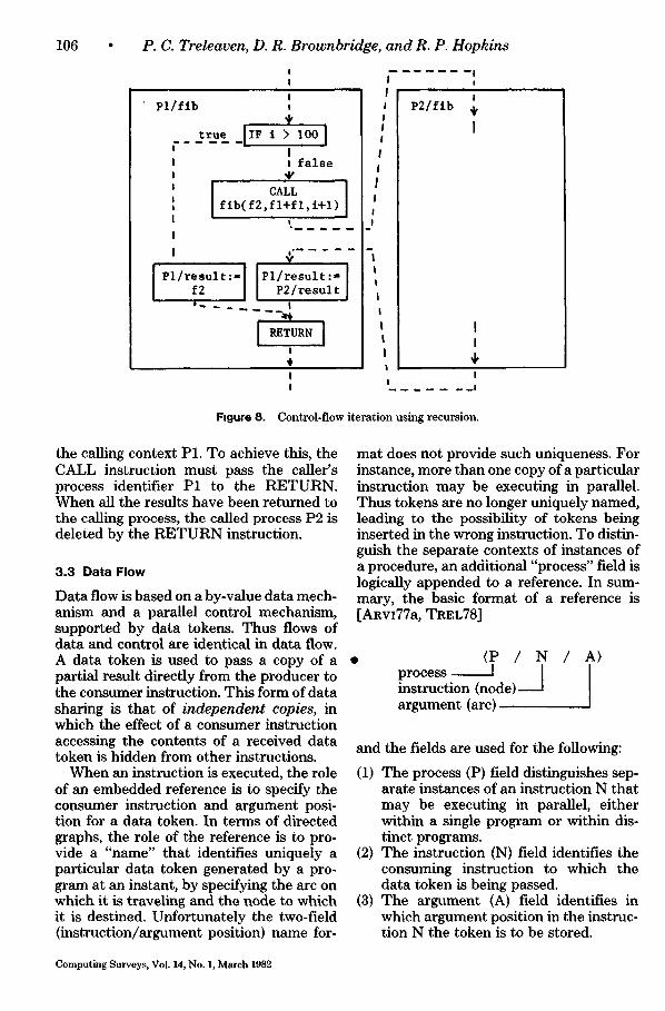
When an instruction is executed, the role of an embedded reference is to specify the consumer instruction and argument posi- tion for a data token. In terms of directed graphs, the role of the reference is to pro- vide a "name" that identifies uniquely a particular data token generated by a pro- gram at an instant, by specifying the arc on which it is traveling and the node to which it is destined. Unfortunately the two-field (instruction/argument position) name for-
mat does not provide such uniqueness. For instance, more than one copy of a particular instruction may be executing in parallel. Thus tokens are no longer uniquely named, leading to the possibility of tokens being inserted in the wrong instruction. To distin- guish the separate contexts of instances of a procedure, an additional "process" field is logically appended to a reference. In sum- mary, the basic format of a reference is [ARvI77a, TREL78]
• A > {P / N / process I I instruction {node) argument {arc)
and the fields are used for the following:
(1) The process (P) field distinguishes sep- arate instances of an instruction N that may be executing in parallel, either within a single program or within dis- tinct programs.
(2) The instruction (N) field identifies the consuming instruction to which the data token is being passed.
(3) The argument (A) field identifies in which argument position in the instruc- tion N the token is to be stored.
Computing Surveys, Vol. 14, No. 1, March 1982
Data-Driven and Demand-Driven Computer Architecture
fl f2 i
+ ~. T.~
answer
÷ ( ) > 10o I
! t r u e / f a l s e
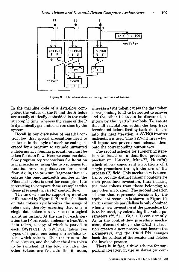
Figure 9. Data-f low i terat ion using feedback of tokens.
• 1 0 7
In the machine code of a data-flow com- puter, the values of the N and the A fields are usually statically embedded in the code at compile time, whereas the value of the P is dynamically generated at run time by the system.
Recall in our discussion of parallel con- trol flow that special precautions need to be taken in the style of machine code gen- erated for a program to exclude unwanted indeterminacy. Similar precautions must be taken for data flow. Here we examine data- flow program representations for iteration and procedures, using the two schemes for iteration previously discussed for control flow. Again, the program fragment that cal- culates the one-hundredth number in the Fibonacci series is used for examples. It is interesting to compare these examples with those previously given for control flow.
The first scheme for supporting iteration is illustrated by Figure 9. Here the feedback of data tokens synchronizes the usage of references, thereby ensuring that only a single data token can ever be on a logical arc at an instant. At the start of each iter- ation the IF instruction releases a true/false data token, a copy of which is passed to each SWITCH. A SWITCH takes two types of inputs: one being a true/false to- ken, which selects either the true or the false outputs, and the other the data token to be switched. If the token is false, the other tokens are fed into the iteration,
whereas a true token causes the data token corresponding to f2 to be routed to answer and the other tokens to be discarded, as shown by the "earth" symbols. To ensure that all calculations within the loop have terminated before feeding back the tokens into the next iteration, a SYNCHronizer instruction is used. The SYNCH fires when all inputs are present and releases them onto the corresponding output arcs.
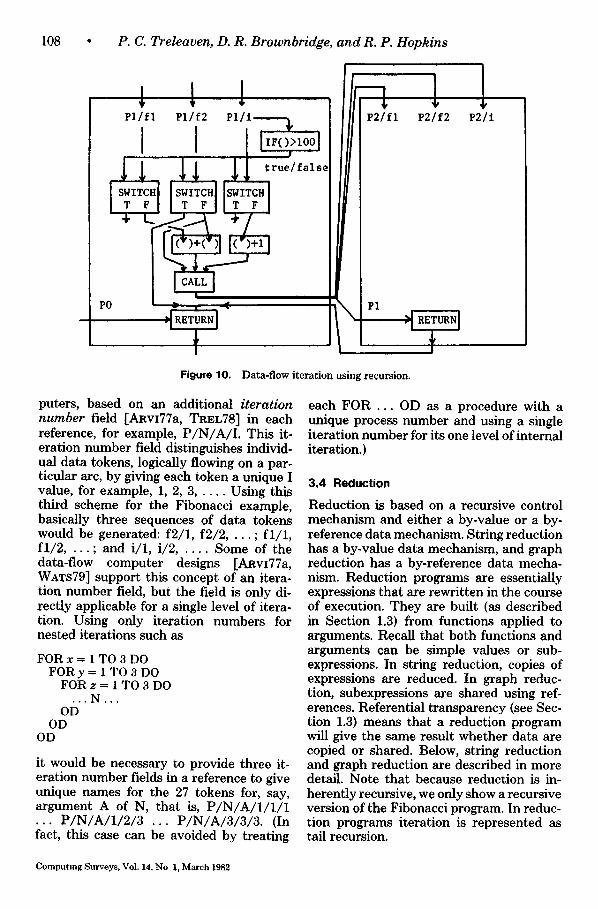
The second scheme for supporting itera- tion is based on a data-flow procedure mechanism [ARvI78, MmA77, HOPK79], which allows concurrent invocations of a single procedure through the use of the process (P) field. This mechanism is essen- tial to provide distinct naming contexts for each procedure invocation, thus isolating the data tokens from those belonging to any other invocation. The second iteration scheme that represents iteration by the equivalent recursion is shown in Figure 10. In this example parallelism is only obtained when a new invocation of the procedure fib is to be used, by calculating the value pa- rameters (f2, f l + f2, i + 1) concurrently. As in the control-flow procedure mecha- nism, discussed above, the CALL instruc- tion creates a new process and inserts the parameters, and the RETURN changes back the context of the results and deletes the invoked process.
There is, in fact, a third scheme for sup- porting iteration in use in data-flow corn-
Computing Surveys, Vol 14, No. 1, March 1982
108 • P. C. Treleaven, D. R. Brownbridge, and R. P. Hopkins
i t i P 1 / f l P1/f2 P1/
I r t r u e / f a l s e
P 2 / f l P2]f2 P2 / i
PO
Figure 10. Data-flow iteration using recursion.
puters, based on an additional iteration number field [ARvI77a, TREL78] in each reference, for example, P /N/A/ I . This it- eration number field distinguishes individ- ual data tokens, logically flowing on a par- ticular arc, by giving each token a unique I value, for example, 1, 2, 3 . . . . . Using this third scheme for the Fibonacci example, basically three sequences of data tokens would be generated: f2/1, f2/2, . . . ; f l /1 , f l / 2 . . . . ; and i/1, i/2 . . . . . Some of the data-flow computer designs [ARvI77a, WATS79] support this concept of an itera- tion number field, but the field is only di- rectly applicable for a single level of itera- tion. Using only iteration numbers for nested iterations such as
FORx ffi 1 TO 3 DO FORy = 1 TO 3 DO
FOR z = 1 TO 3 DO . - . N . , ,
OD OD
OD
it would be necessary to provide three it- eration number fields in a reference to give unique names for the 27 tokens for, say, argument A of N, that is, P / N / A / I / I / 1 . . . P / N / A / I / 2 / 3 . . . P /N/A/3/3 /3 . (In fact, this case can be avoided by treating
each FOR . . . OD as a procedure with a unique process number and using a single iteration number for its one level of internal iteration.)
3.4 Reduction
Reduction is based on a recursive control mechanism and either a by-value or a by- reference data mechanism. String reduction has a by-value data mechanism, and graph reduction has a by-reference data mecha- nism. Reduction programs are essentially expressions that are rewritten in the course of execution. They are built (as described in Section 1.3) from functions applied to arguments. Recall that both functions and arguments can be simple values or sub- expressions. In string reduction, copies of expressions are reduced. In graph reduc- tion, subexpressions are shared using ref- erences. Referential transparency (see Sec- tion 1.3) means that a reduction program will give the same result whether data are copied or shared. Below, string reduction and graph reduction are described in more detail. Note that because reduction is in- herently recursive, we only show a recursive version of the Fibonacci program. In reduc- tion programs iteration is represented as tail recursion.
Computing Surveys, VoL 14, No 1, March 1982
Data-Driven a n d Demand-Dr iven Computer Arch i tec ture •
Initial Expression:
( answer ) WHERE answer - f ib (i, I, 3);
fib (fl, f2, i) " IF I > i00 THEN f2 ELSE fib (f2, fl+f2, l+l) FI;
First Reduction:
( IF 3 > I00 THEN 1 ELSE fib (I, I+i, 3+1) FI )
Next Reductions:
( IF FALSE THEN I ELSE fib (I, i+I, 3+1) FI )
( fib (i, i+I, 3+1) )
( f i b (1, 2, 4) )
( fib (2, 3, 5) ) ... ( fib (3, 5, 6) ) ... ( fib (5, 8, 7) )
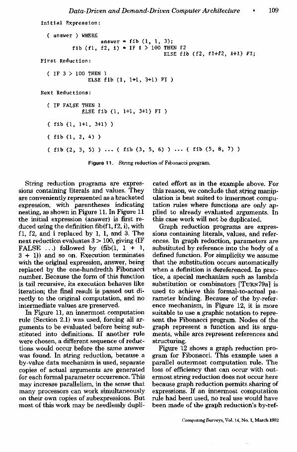
Figure 11. Stnngreduc~on of Flbonacciprogram.
109
String reduction programs are expres- sions containing literals and values. They are conveniently represented as a bracketed expression, with parentheses indicating nesting, as shown in Figure 11. In Figure 11 the initial expression (answer) is first re- duced using the definition fib(fl, f2, i), with fl , f2, and i replaced by 1, 1, and 3. The next reduction evaluates 3 > 100, giving (IF FALSE . . . ) followed by (fib(l, 1 + 1, 3 + 1)) and so on. Execution terminates with the original expression, answer, being replaced by the one-hundredth Fibonacci number. Because the form of this function is tail recursive, its execution behaves like iteration; the final result is passed out di- rectly to the original computation, and no intermediate values are preserved.
In Figure 11, an innermost computation rule (Section 2.1) was used, forcing all ar- guments to be evaluated before being sub- stituted into definitions. If another rule were chosen, a different sequence of reduc- tions would occur before the same answer was found. In string reduction, because a by-value data mechanism is used, separate copies of actual arguments are generated for each formal parameter occurrence. This may increase parallelism, in the sense that many processors can work simultaneously on their own copies of subexpressions. But most of this work may be needlessly dupli-
cated effort as in the example above. For this reason, we conclude that string manip- ulation is best suited to innermost compu- tation rules where functions are only ap- plied to already evaluated arguments. In this case work will not be duplicated.
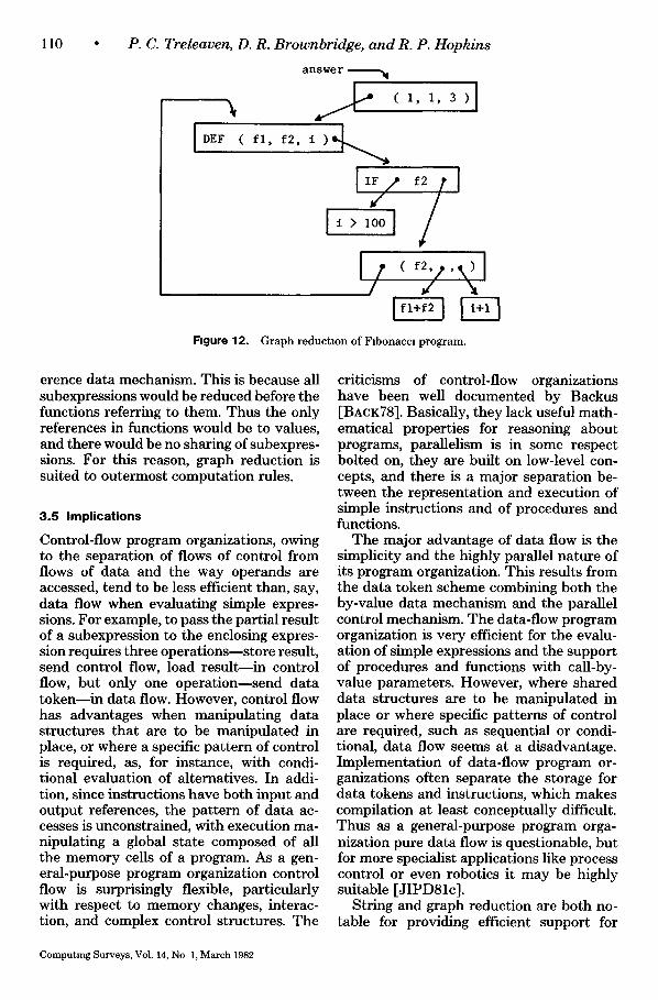
Graph reduction programs are expres- sions containing literals, values, and refer- ences. In graph reduction, parameters are substituted by reference into the body of a defined function. For simplicity we assume that the substitution occurs automatically when a definition is dereferenced. In prac- tice, a special mechanism such as lambda substitution or combinators [TURN79a] is used to achieve this formal-to-actual pa- rameter binding. Because of the by-refer- ence mechanism, in Figure 12, it is more suitable to use a graphic notation to repre- sent the Fibonacci program. Nodes of the graph represent a function and its argu- ments, while arcs represent references and structuring.
Figure 12 shows a graph reduction pro- gram for Fibonacci. This example uses a parallel outermost computation rule. The loss of efficiency that can occur with out- ermost string reduction does not occur here because graph reduction permits sharing of expressions. If an innermost computation rule had been used, no real use would have been made of the graph reduction's by-ref-
Computing Surveys, Vol. 14, No. I, March 1982
110 • P. C. Treleaven, D. R. Brownbridge, and R. P. Hopkins
answer W
DEF ( f l , f2, t ) @ ~
Figure 12. Graph reduction of Flbonaccl program.
erence data mechanism. This is because all subexpressions would be reduced before the functions referring to them. Thus the only references in functions would be to values, and there would be no sharing of subexpres- sions. For this reason, graph reduction is suited to outermost computation rules.
3.5 Implications
Control-flow program organizations, owing to the separation of flows of control from flows of data and the way operands are accessed, tend to be less efficient than, say, data flow when evaluating simple expres- sions. For example, to pass the partial result of a subexpression to the enclosing expres- sion requires three operations--store result, send control flow, load result--in control flow, but only one operation--send data token--in data flow. However, control flow has advantages when manipulating data structures that are to be manipulated in place, or where a specific pattern of control is required, as, for instance, with condi- tional evaluation of alternatives. In addi- tion, since instructions have both input and output references, the pattern of data ac- cesses is unconstrained, with execution ma- nipulating a global state composed of all the memory cells of a program. As a gen- eral-purpose program organization control flow is surprisingly flexible, particularly with respect to memory changes, interac- tion, and complex control structures. The
criticisms of control-flow organizations have been well documented by Backus [BACK78]. Basically, they lack useful math- ematical properties for reasoning about programs, parallelism is in some respect bolted on, they are built on low-level con- cepts, and there is a major separation be- tween the representation and execution of simple instructions and of procedures and functions.
The major advantage of data flow is the simplicity and the highly parallel nature of its program organization. This results from the data token scheme combining both the by-value data mechanism and the parallel control mechanism. The data-flow program organization is very efficient for the evalu- ation of simple expressions and the support of procedures and functions with call-by- value parameters. However, where shared data structures are to be manipulated in place or where specific patterns of control are required, such as sequential or condi- tional, data flow seems at a disadvantage. Implementation of data-flow program or- ganizations often separate the storage for data tokens and instructions, which makes compilation at least conceptually difficult. Thus as a general-purpose program orga- nization pure data flow is questionable, but for more specialist applications like process control or even robotics it may be highly suitable [JIPD81c].
String and graph reduction are both no- table for providing efficient support for
Computing Surveys, Vol. 14, No 1, March 1982
Data-Driven and Demand-Driven Computer Architecture • 111
functional programming, which is growing in interest. Graph reduction has a by-ref- erence data mechanism that allows sharing and allows manipulation of unevaluated ob- jects. String reduction has a by-value data mechanism and so has minimal addressing overheads. The nature of functional pro- grams makes them suitable for parallel evaluation; referential transparency makes reductions independent of context and se- quencing. Graph manipulation allows arbi- trary objects to be manipulated without their being evaluated. This means that in- finite data structures can conceptually be used as long as only the values of some finite part of them are demanded.
In graph reduction, structures are repre- sented by a reference until their contents are needed; because references are gener- ally smaller than structures, they are more efficient to manipulate. In string reduction, structures are represented by value, and so their contents are duplicated at many points in the program; thus their contents are available locally, without a referenced value being fetched from elsewhere. Last, for reduction program organizations to be- come candidates for general-purpose com- puting, it is necessary for functional pro- gramming language to become the most widely used style of programming.
4. MACHINE ORGANIZATION
We use the term machine organization to cover the way a machine's resources are configured and allocated to support a pro- gram organization. This section starts by classifying the machine organizations being used in data-driven and demand-driven computers.
4.1 Classification
An examination of the data- and demand- driven computer architectures under devel- opment reveals three basic classes of ma- chine organization, which we call central- ized, packet communication, and expres- sion manipulation.
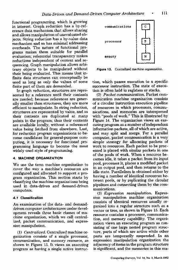
(1) Centralized. Centralized machine or- ganization consists of a single processor, communication, and memory resource, as shown in Figure 13. It views an executing program as having a single active instruc-
communications
processor
memory
i ,
D
Figure 13. Centralized mach ine orgamzation.
tion, which passes execution to a specific successor instruction. The state of execu- tion is often held in registers or stacks.
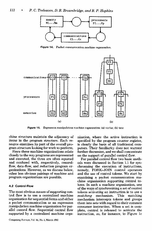
(2) Packet communication. Packet com- munication machine organization consists of a circular instruction execution pipeline of resources in which processors, commu- nications, and memories are interspersed with "pools of work." This is illustrated by Figure 14. The organization views an exe- cuting program as a number of independent information packets, all of which are active, and may split and merge. For a parallel computer, packet communication is a very simple strategy for allocating packets of work to resources. Each packet to be proc- essed is placed with similar packets in one of the pools of work. When a resource be- comes idle, it takes a packet from its input pool, processes it, places a modified packet in an output pool, and then returns to the idle state. Parallelism is obtained either by having a number of identical resources be- tween pools, or by replicating the circular pipelines and connecting them by the com- munications.
(3) Expression manipulation. Expres- sion manipulation machine organization consists of identical resources usually or- ganized into a regular structure such as a vector or tree, as shown in Figure 15. Each resource contains a processor, communica- tion, and memory capability. The organi- zation views an executing program as con- sisting of one large nested program struc- ture, parts of which are active while other parts are temporarily suspended. In an expression manipulation organization the adjacency of items in the program structure is significant, and the memories in this ma-
Computing Surveys, Vol 14, No 1, March 1982
112 P. C. Treleaven, D. R. Brownbridge, and R. P. Hopkins
U . _ j I c l . . . c c I" " - J Figure 14. Packet commumcat ion machine orgamzation.
communications-
processors
meMor i e s
Figure 15,
, I F i l
(a) (b)
Expresston manipulat ion machine orgamzation: (a) vector; (b) tree
chine structure maintain the adjacency of items in the program structure. Each re- source examines its part of the overall pro- gram structure looking for work to perform.
Since these machine organizations relate closely to the way programs are represented and executed, the three are often equated and confused with, respectively, control- flow, data-flow, and reduction program or- ganizations. However, as we discuss below, other less obvious pairings of machine and program organizations are possible.
4 , 2 C o n t r o l F l o w
The most obvious means of supporting con- trol flow is to use a centralized machine organization for sequential forms and either a packet communication or an expression manipulation machine organization for par- allel control flow. Sequential control flow supported by a centralized machine orga-
nization, where the active instruction is specified by the program counter register, is clearly the basis of all traditional com- puters. Their familiarity does not warrant further discussion, and we shall concentrate on the support of parallel control flow.
For parallel control flow two basic meth- ods were discussed in Section 1.1 for syn- chronizing the execution of instructions, namely, FORK-JOIN control operators and the use of control tokens. We start by examining a packet communication ma- chine organization supporting control to- kens. In such a machine organization, one of the ways of synchronizing a set of control tokens activating an instruction is to use a matching mechanism. This matching mechanism intercepts tokens and groups them into sets with regard to their common consumer instruction. When a set is com- plete, control is released to activate the instruction, as, for instance, in Figure lc
Cornputmg Surveys, Vol 14, No. 1, March 1982
Data-Driven and Demand-Driven Computer Architecture
Matching I Unlt I
T control tokens )
[
I Memory ] Unlt
MI...Mm
-/qnstructlon~ J Fetch/ [ "'addresses J "I Update I
l ata t° | s t o r e ~ff . ~ ~.
~'executable~ / k nstructl°nsJ
t I
Figure 16. Control-flow packet commumcatlons.
• 113
with tokens i3/0 and i3/1, which forms a set destined for instruction i3. An example of such a matching scheme is proposed in FARR79 and HOPK79.
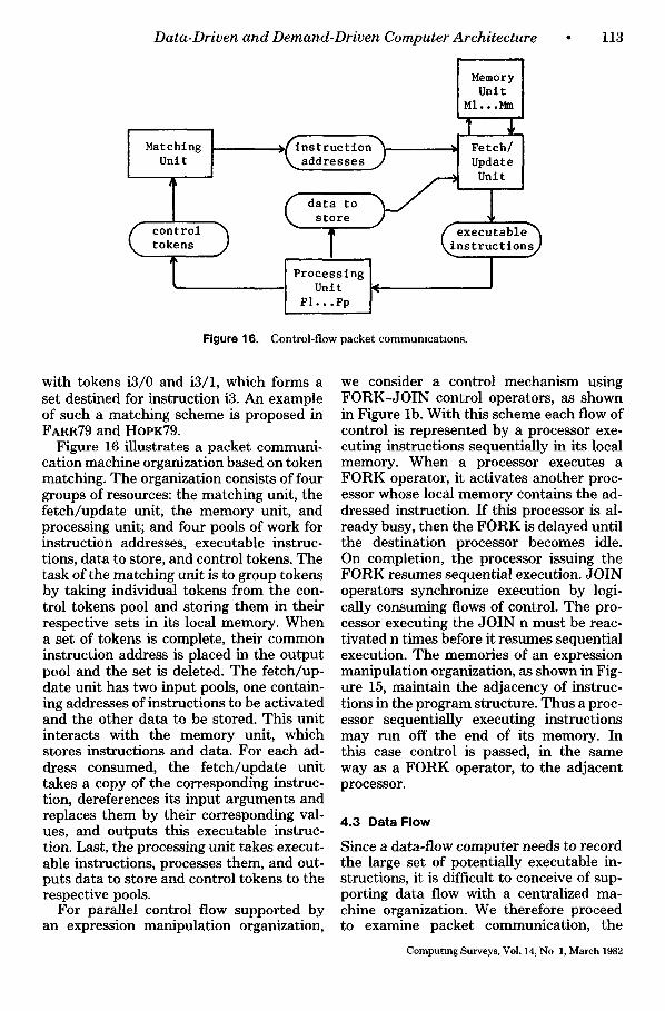
Figure 16 illustrates a packet communi- cation machine organization based on token matching. The organization consists of four groups of resources: the matching unit, the fetch/update unit, the memory unit, and processing unit; and four pools of work for instruction addresses, executable instruc- tions, data to store, and control tokens. The task of the matching unit is to group tokens by taking individual tokens from the con- trol tokens pool and storing them in their respective sets in its local memory. When a set of tokens is complete, their common instruction address is placed in the output pool and the set is deleted. The fetch/up- date unit has two input pools, one contain- ing addresses of instructions to be activated and the other data to be stored. This unit interacts with the memory unit, which stores instructions and data. For each ad- dress consumed, the fetch/update unit takes a copy of the corresponding instruc- tion, dereferences its input arguments and replaces them by their corresponding val- ues, and outputs this executable instruc- tion. Last, the processing unit takes execut- able instructions, processes them, and out- puts data to store and control tokens to the respective pools.
For parallel control flow supported by an expression manipulation organization,
we consider a control mechanism using FORK-JOIN control operators, as shown in Figure lb. With this scheme each flow of control is represented by a processor exe- cuting instructions sequentially in its local memory. When a processor executes a FORK operator, it activates another proc- essor whose local memory contains the ad- dressed instruction. If this processor is al- ready busy, then the FORK is delayed until the destination processor becomes idle. On completion, the processor issuing the FORK resumes sequential execution. JOIN operators synchronize execution by logi- cally consuming flows of control. The pro- cessor executing the JOIN n must be reac- tivated n times before it resumes sequential execution. The memories of an expression manipulation organization, as shown in Fig- ure 15, maintain the adjacency of instruc- tions in the program structure. Thus a proc- essor sequentially executing instructions may run off the end of its memory. In this case control is passed, in the same way as a FORK operator, to the adjacent processor.
4.3 Data Flow
Since a data-flow computer needs to record the large set of potentially executable in- structions, it is difficult to conceive of sup- porting data flow with a centralized ma- chine organization. We therefore proceed to examine packet communication, the
Computmg Surveys, Vol. 14, No 1, March 1982
114 P. C. Treleaven, D. R. Brownbridge, and R. P. Hopkins
Update Unit
tokens PI. • .Pp
J Memory [ Unit ( -I [
.(Instructlon h .I Fetch I "~addresses ] 7 Unit
Processing L fexecutable h Unit ~Instructlon]
Figure 17. Data-flow packet communwation with token storage.
Matching ] ./¢ sets of ~'~ Unit [ "~,~ tokens ~)
] data
tokens > Processing Unit
PI...Pn
Memory I Unit Ml...~
J Fetch/ [ l Update
unit
1 ~_._~ executable~ ~nstructiou~
Figure 18. Data-flow packet communication with token matching
most obvious machine organization for sup- porting data flow.
Instruction execution in data-flow com- puters is, in general, controlled by either of two synchronization schemes [DENN79b], which we refer to as token storage and token matching. In the first scheme data tokens are actually stored into an instruc- tion or a copy of the instruction, and an instruction executes when it has received all its inputs. Examples of this scheme in- clude the Massachusetts Institute of Tech- nology [DENN79a] and Texas Instruments [CORN79] data-flow computers. In the sec- ond scheme a token-matching mechanism, as described above, is employed. When a set of data tokens is complete, the set is released to activate the consumer instruc- t ion-as , for instance, in Figure 2, with i 2 /1 : -4 and i2/2:ffi2, which form a set of tokens (4, 2) for instruction i2. Examples of this scheme include Irvine Data Flow
Computing Surveys, Vol. 14, No 1, March 1982
[ARVIS(}a], the Manchester Data Flow Sys- tem [WATS79], and the Newcastle Data- Control Flow Computer [HoPK79].
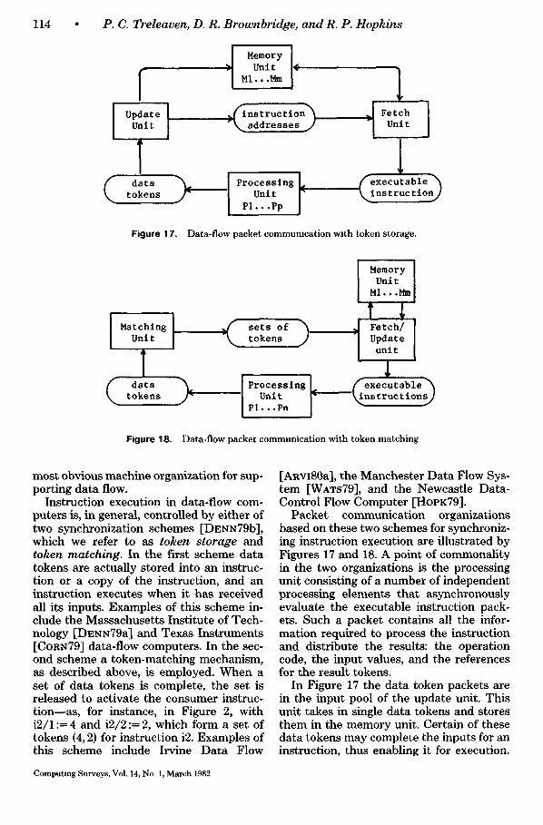
Packet communication organizations based on these two schemes for synchroniz- ing instruction execution are illustrated by Figures 17 and 18. A point of commonality in the two organizations is the processing unit consisting of a number of independent processing elements that asynchronously evaluate the executable instruction pack- ets. Such a packet contains all the infor- mation required to process the instruction and distribute the results: the operation code, the input values, and the references for the result tokens.
In Figure 17 the data token packets are in the input pool of the update unit. This unit takes in single data tokens and stores them in the memory unit. Certain of these data tokens may complete the inputs for an instruction, thus enabling it for execution.
Data-Driven and Demand-Driven Computer Architecture • 115
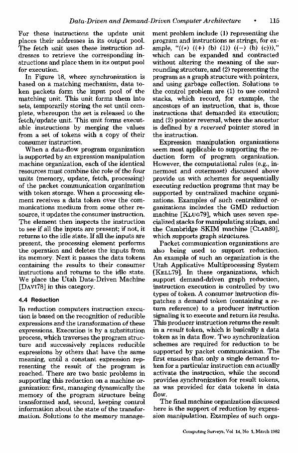
For these instructions the update unit places their addresses in its output pool. The fetch unit uses these instruction ad- dresses to retrieve the corresponding in- structions and place them in its output pool for execution.
In Figure 18, where synchronization is based on a matching mechanism, data to- ken packets form the input pool of the matching unit. This unit forms them into sets, temporarily storing the set until com- plete, whereupon the set is released to the fetch/update unit. This unit forms execut- able instructions by merging the values from a set of tokens with a copy of their consumer instruction.
When a data-flow program organization is supported by an expression manipulation machine organization, each of the identical resources must combine the role of the four units (memory, update, fetch, processing) of the packet communication organization with token storage. When a processing ele- ment receives a data token over the com- munications medium from some other re- source, it updates the consumer instruction. The element then inspects the instruction to see if all the inputs are present; if not, it returns to the idle state. If all the inputs are present, the processing element performs the operation and deletes the inputs from its memory. Next it passes the data tokens containing the results to their consumer instructions and returns to the idle state. We place the Utah Data-Driven Machine [DAvI78] in this category.
4.4 Reduction
In reduction computers instruction execu- tion is based on the recognition of reducible expressions and the transformation of these expressions. Execution is by a substitution process, which traverses the program struc- ture and successively replaces reducible expressions by others that have the same meaning, until a constant expression rep- resenting the result of the program is reached. There are two basic problems in supporting this reduction on a machine or- ganization: first, managing dynamically the memory of the program structure being transformed and, second, keeping control information about the state of the transfor- mation. Solutions to the memory manage-
ment problem include (1) representing the program and instructions as strings, for ex- ample, "((*) ((+) (b) (1)) ((-) (b) (c)))," which can be expanded and contracted without altering the meaning of the sur- rounding structure, and (2) representing the program as a graph structure with pointers, and using garbage collection. Solutions to the control problem are (1) to use control stacks, which record, for example, the ancestors of an instruction, that is, those instructions that demanded its execution; and (2) pointer reversal, where the ancestor is defined by a reversed pointer stored in the instruction.
Expression manipulation organizations seem most applicable to supporting the re- duction form of program organization. However, the computational rules (e.g., in- nermost and outermost) discussed above provide us with schemes for sequentially executing reduction programs that may be supported by centralized machine organi- zations. Examples of such centralized or- ganizations includes the GMD reduction machine [KLUG79], which uses seven spe- cialized stacks for manipulating strings, and the Cambridge SKIM machine [CLAR80], which supports graph structures.
Packet communication organizations are also being used to support reduction. An example of such an organization is the Utah Applicative Multiprocessing System [Kv, LL79]. In these organizations, which support demand-driven graph reduction, instruction execution is controlled by two types of token. A consumer instruction dis- patches a demand token (containing a re- turn reference) to a producer instruction signaling it to execute and return its results. This producer instruction returns the result in a result token, which is basically a data token as in data flow. Two synchronization schemes are required for reduction to be supported by packet communication. The first ensures that only a single demand to- ken for a particular instruction can actually activate the instruction, while the second provides synchronization for result tokens, as was provided for data tokens in data flow.
The final machine organization discussed here is the support of reduction by expres- sion manipulation. Examples of such orga-
Computing Surveys, Vol 14, No 1, March 1982
116 ° P.C. Treleaven, D. R. Brownbridge, and R. P. Hopkins
Memories Stage
Ml M2 M3 M4 M5 M6
1 (* t l t 2 ) - - t l : ( + b l ) t 2 : ( - b c ) b : ( 4 ) c : ( 2 )
2 (* ( + b 1) i 2 )
3 (* ( + b 1) (-bc))
4 ( , (+ 4 1) (- 4 2))
5 (* 5 2)
Figure 19. Reduction expression mampulatmn.
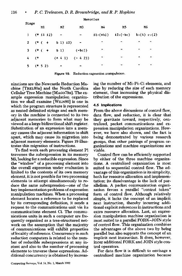
nizations are the Newcastle Reduction Ma- chine [TREL80a] and the North Carolina Cellular Tree Machine [MAGo79a]. The ex- ample expression manipulation organiza- tion we shall examine [WILNS0] is one in which the program structure is represented as nested delimited strings and each mem- ory in the machine is connected to its two adjacent memories to form what may be viewed as a large bidirectional shift register. Substitution of an expression into a mem- ory causes the adjacent information to shift apart, which may cause its migration into adjacent memory elements. Figure 19 illus- trates this migration of instructions.
To find work each processing element Pi traverses the subexpression in its memory Mi, looking for a reducible expression. Since the "window" of a processing element into the overall expression under evaluation is limited to the contents of its own memory element, it is not possible for two processing elements to attempt simultaneously to re- duce the same subexpression--one of the key implementation problems of expression manipulation machines. When a processing element locates a reference to be replaced by its corresponding definition, it sends a request to the communications unit via its communications element Ci. The commu- nications units in such a computer are fre- quently organized as a tree-structured net- work on the assumption that the majority of communications will exhibit properties of locality of reference. Concurrency in such reduction computers is related to the num- ber of reducible subexpressions at any in- stant and also to the number of processing elements to traverse these expressions. Ad- ditional concurrency is obtained by increas-
ing the number of Mi-PioCi elements, and also by reducing the size of each memory element, thus increasing the physical dis- tribution of the expressions.
4.5 Implications From the above discussions of control flow, data flow, and reduction, it is clear that they gravitate toward, respectively, cen- tralized, packet communications and ex- pression manipulation organizations. How- ever, we have also shown, and the fact is being demonstrated by various research groups, that other pairings of program or- ganizations and machine organizations are viable.
Control flow can be efficiently supported by either of the three machine organiza- tions. A centralized organization is most suited to sequential control flow. The ad- vantage of this organization is its simplicity, both for resource allocation and implemen- tation; its disadvantage is the lack of par- allelism. A packet communication organi- zation favors a parallel "control token" form of control flow. Although relatively simple, it lacks the concept of an implicit next instruction, thereby incurring addi- tional explicit references in instructions and extra resource allocation. Last, an expres- sion manipulation machine organization is most suited to a parallel FORK-JOIN style of control flow. This organization combines the advantages of the above two by being parallel but also supports the concept of an implicit next instruction. It does, however, incur additional FORK and JOIN style con- trol operators.
For data flow it is difficult to envisage a centralized machine organization because
Computing Surveys, Vol. 14, No. 1, March 1982
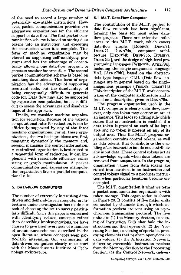
Data-Driven and Demand-Driven Computer Architecture
of the need to record a large number of potentially executable instructions. How- ever, packet communication provides two alternative organizations for the efficient support of data flow. The first packet com- munication scheme is based on storing data tokens into an instruction and executing the instruction when it is complete. This form of machine organization may be viewed as supporting self-modifying pro- grams and has the advantage of concep- tually allowing one data-flow program to generate another for execution. The second packet communication scheme is based on matching data tokens. This form of orga- nization has the advantage of supporting reentrant code, but the disadvantage of being conceptually difficult to generate code for. Data flow may also be supported by expression manipulation, but it is diffi- cult to assess the advantages and disadvan- tages of this approach.
Finally, we consider machine organiza- tion for reduction. Because of the various computational rules for reduction, it can be efficiently supported by any of the three machine organizations. For all these orga- nizations, the two basic problems are, first, managing dynamically the memory and, second, managing the control information. A centralized organization is best suited to a sequential form of reduction. It can im- plement with reasonable efficiency either string or graph manipulation. A packet communication and expression manipula- tion organization favor a parallel computa- tional rule.
5. DATA-FLOW COMPUTERS
The number of extremely interesting data- driven and demand-driven computer archi- tectures under investigation has made our task of choosing the set to survey particu- larly difficult. Since this paper is concerned with identifying related concepts rather than describing implementations, we have chosen to give brief overviews of a number of architecture schemes, described in the open literature, whose concepts seem par- ticularly interesting. Our examination of data-driven computers clearly must start with the Massachusetts Institute of Tech- nology architecture.
• 1 1 7
5.1 M.I.T. Data-Flow Computer
The contribution of the M.I.T. project to data-flow research has been significant, forming the basis for most other data- flow projects. There are extensive refer- ences to this M.I.T. work, which covers data-flow graphs [RODR69, DENN71, DENS72, DESN74a], computer archi- tecture [DENN74b, DENN75b, RUMB77, DENS79a], and the design of high-level pro- gramming languages [WENG75, ACKE79a], including the single-assignment language VAL [ACKE79b], based on the abstract- data-type language CLU. (Data-flow lan- guages are in general based on the single- assignment principle [TESL68, C~IAM71].) This description of the M.I.T. work concen- trates on the computer architecture and is based on a description given in Dm~N79a.
The program organization used in the M.I.T. computer is clearly data flow; how- ever, only one token may occupy an arc at an instance. This leads to a fwing rule which states that an instruction is enabled if a data token is present on each of its input arcs and no token is present on any of its output arcs. Thus the M.I.T. program or- ganization contains control tokens, as well as data tokens, that contribute to the ena- bling of an instruction but do not contribute any input data. These control tokens act as acknowledge signals when data tokens are removed from output arcs. In the program, organization values from data tokens are stored into locations in an instruction and control tokens signal to a producer instruc- tion when particular locations become un- occupied.
The M.I.T. organization is what we term a packet communication organization with token storage. This organization is shown in Figure 20. It consists of five major units connected by channels through which in- formation packets are sent using an asyn- chronous transmission protocol. The five units are (1) the Memory Section, consist- ing of Instruction Cells that hold the in- structions and their operands; (2) the Proc- essing Section, consisting of specialist proc- essing elements that perform operations on data values; (3) the Arbitration Network, delivering executable instruction packets from the Memory Section to the Processing Section; (4) the Control Network, deliver-
Computing Surveys, Vol 14, No 1, March 1982
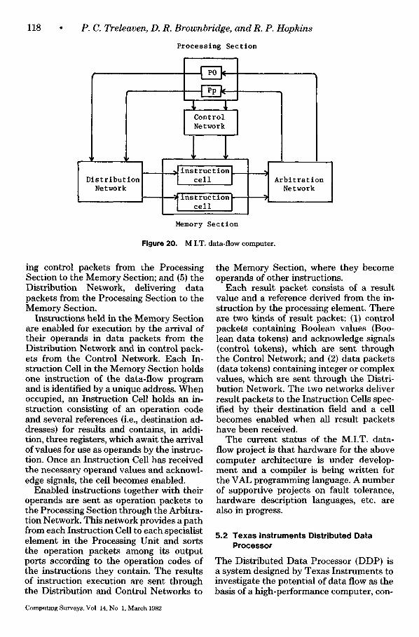
118 P. C. Treleaven, D. R. Brownbridge, and R. P. Hopkins
p
Distribution Network
Processing Section
Control i Network
~ ins t ruct ton | c e l l ]
tnstructton; cel l I
Memory Section
J I Arbitration
Network ¢i
Figure 20. M I.T. data-flow computer .
ing control packets from the Processing Section to the Memory Section; and (5) the Distribution Network, delivering data packets from the Processing Section to the Memory Section.
Instructions held in the Memory Section are enabled for execution by the arrival of their operands in data packets from the Distribution Network and in control pack- ets from the Control Network. Each In- struction Cell in the Memory Section holds one instruction of the data-flow program and is identified by a unique address. When occupied, an Instruction Cell holds an in- struction consisting of an operation code and several references (i.e., destination ad- dresses) for results and contains, in addi- tion, three registers, which await the arrival of values for use as operands by the instruc- tion. Once an Instruction Cell has received the necessary operand values and acknowl- edge signals, the cell becomes enabled.
Enabled instructions together with their operands are sent as operation packets to the Processing Section through the Arbitra- tion Network. This network provides a path from each Instruction Cell to each specialist element in the Processing Unit and sorts the operation packets among its output ports according to the operation codes of the instructions they contain. The results of instruction execution are sent through the Distribution and Control Networks to
the Memory Section, where they become operands of other instructions.
Each result packet consists of a result value and a reference derived from the in- struction by the processing element. There are two kinds of result packet: (1) control packets containing Boolean values (Boo- lean data tokens) and acknowledge signals (control tokens), which are sent through the Control Network; and (2) data packets (data tokens) containing integer or complex values, which are sent through the Distri- bution Network. The two networks deliver result packets to the Instruction Cells spec- ified by their destination field and a cell becomes enabled when all result packets have been received.
The current status of the M.I.T. data- flow project is that hardware for the above computer architecture is under develop- ment and a compiler is being written for the VAL programming language. A number of supportive projects on fault tolerance, hardware description languages, etc. are also in progress.
5.2 Texas Instruments Distributed Data Processor
The Distributed Data Processor (DDP) is a system designed by Texas Instruments to investigate the potential of data flow as the basis of a high-performance computer, con-
Computing Surveys, Vol 14, No 1, March 1982
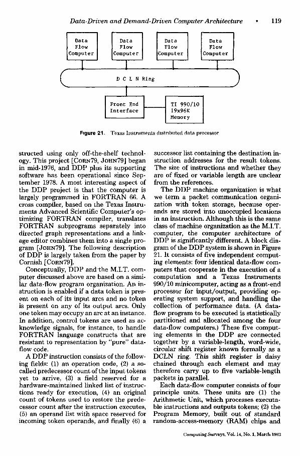
Data-Driven and Demand-Dr iven Computer Arch i tec ture • 119
Data Flow
Computer
(
D a t a Flow
Computer Data I Flow
omputer
D C L N R i n g
r
D a t a Flow
Computer
L l [ 1
Front End TI 990/10 Interface 19x96K
Memory
Figure 21. Texas I n s t r u m e n t s d is t r ibuted da ta processor
)
structed using only off-the-shelf technol- ogy. This project [CORN79, JOHN79] began in mid-1976, and DDP plus its supporting software has been operational since Sep- tember 1978. A most interesting aspect of the DDP project is that the computer is largely programmed in FORTRAN 66. A cross compiler, based on the Texas Instru- ments Advanced Scientific Computer's op- timizing FORTRAN compiler, translates FORTRAN subprograms separately into directed graph representations and a link- age editor combines them into a single pro- gram [JOHN79]. The following description of DDP is largely taken from the paper by Cornish [CORN79].
Conceptually, DDP and'the M.I.T. com- puter discussed above are based on a simi- lar data-flow program organization. An in- struction is enabled if a data token is pres- ent on each of its input arcs and no token is present on any of its output arcs. Only one token may occupy an arc at an instance. In addition, control tokens are used as ac- knowledge signals, for instance, to handle FORTRAN language constructs that are resistant to representation by "pure" data- flow code.
A DDP instruction consists of the follow- ing fields: (1) an operation code, (2) a so- called predecessor count of the input tokens yet to arrive, (3) a field reserved for a hardware-maintained linked list of instruc- tions ready for execution, (4) an original count of tokens used to restore the prede- cessor count after the instruction executes, (5) an operand list with space reserved for incoming token operands, and finally (6) a
successor list containing the destination in- struction addresses for the result tokens. The size of instructions and whether they are of fixed or variable length are unclear from the references.
The DDP machine organization is what we term a packet communication organi- zation with token storage, because oper- ands are stored into unoccupied locations in an instruction. Although this is the same class of machine organization as the M.I.T. computer, the computer architecture of DDP is significantly different. A block dia- gram of the DDP system is shown in Figure 21. It consists of five independent comput- ing elements: four identical data-flow com- puters that cooperate in the execution of a computation and a Texas Instruments 990/10 minicomputer, acting as a front-end processor for input/output, providing op- erating system support, and handling the collection of performance data. (A data- flow program to be executed is statistically partitioned and allocated among the four data-flow computers.) These five comput- ing elements in the DDP are connected together by a variable-length, word-wide, circular shift register known formally as a DCLN ring. This shift register is daisy chained through each element and may therefore carry up to five variable-length packets in parallel.
Each data-flow computer consists of four principle units. These units are (1) the Arithmetic Unit, which processes executa- ble instructions and outputs tokens; (2) the Program Memory, built out of standard random-access-memory (RAM) chips and
Computing Surveys, Vol. 14, No. 1, March 1982
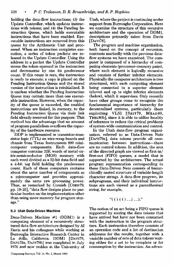
120 • P.C. Treleaven, D. R. Brownbridge, and R. P. Hopkins
holding the data-flow instructions; (3) the Update Controller, which updates instruc- tions with tokens; and (4) the Pending In- struction Queue, which holds executable instructions that have been enabled. Exe- cutable instructions are removed from this queue by the Arithmetic Unit and proc- essed. When an instruction completes exe- cution, a series of token packets are re- leased to the Update Controller. Using the address in a packet the Update Controller stores the token operand in the instruction and decrements by one its predecessor count. If this count is zero, the instruction is ready to execute; a copy is placed on the Pending Instruction Queue and the stored version of the instruction is reinitialized. It is unclear whether the Pending Instruction Queue may contain more than one execut- able instruction. However, when the capac- ity of the queue is exceeded, the enabled instructions are linked, in memory, to the Pending Instruction Queue via their link field already reserved for this purpose. This method has the advantage that no amount of program parallelism overflows the capac- ity of the hardware resource.
DDP is implemented in transistor-tran- sistor logic (TTL) on wire-wrap boards and chassis from Texas Instruments 990 mini- computer components. Each data-flow computer contains 32K words of metal-ox- ide-semiconductor (MOS) memory with each word divided as a 32-bit data field and a 4-bit tag field holding the predecessor count. Each of these computers contains about the same number of components as a minicomputer and provides approxi- mately the same raw processing power. Thus, as remarked by Cornish [CORN79, pp. 19-25], "data flow designs place no par- ticular burden on the implementation other than using more memory for program stor- age."
5.3 Utah Data-Driven Machine
Data-Driven Machine #1 (DDM1) is a computing element of a recursively struc- tured data-flow architecture designed by A1 Davis and his colleagues while working at Burroughs Interactive Research Center in La Jolla, California. DDM1 [DAvI78, DAVI79a, DAvI79b] was completed in July 1976 and now resides at the University of
Utah, where the project is continuing under support from Burroughs Corporation. Here we examine the structure of this recursive architecture and the operation of DDM1, descriptions primarily taken from Davis [DAvI78].
The program and machine organization, both based on the concept of recursion, contrasts markedly with the previous data- flow systems we have examined. The com- puter is composed of a hierarchy of com- puting elements (processor-memory pairs), where each element is logically recursive and consists of further inferior elements. Physically the computer architecture is tree structured, with each computing element being connected to a superior element (above) and up to eight inferior elements (below), which it supervises. Only recently have other groups come to recognize the fundamental importance of hierarchy for decentralized systems, particularly those exploiting VLSI [SEIT79, MEAD80, TREL80b], since it is able to utilize locality of reference to reduce the critical problems of system-wide communication and control.
In the Utah data-flow program organi- zation, referred to as Data-Driven Nets [DAvI79a], data tokens provide all com- munication between instructions--there are no control tokens. In addition, the arcs of the directed graph are viewed as first-in/ first-out (FIFO) queues, a model that is supported by the architecture. The actual program representation corresponding to these Data-Driven Nets consists of hierar- chically nested structure of variable-length character strings. A data-flow program, its subprograms, and their individual instruc- tions are each viewed as a parenthesized string, for example,
"( ( ) ( ( ) . . . ) . . . ) ."
The notion of an arc being a FIFO queue is supported by storing the data tokens that have arrived but have not been consumed with the instruction in the program struc- ture. Each instruction therefore consists of an operation code and a list of destination addresses for the results, together with a variable number of sets of data tokens wait- ing either for a set to be complete or for consumption by the instruction. An advan-
Computing Surveys, Vol 14, No. 1, March 1982
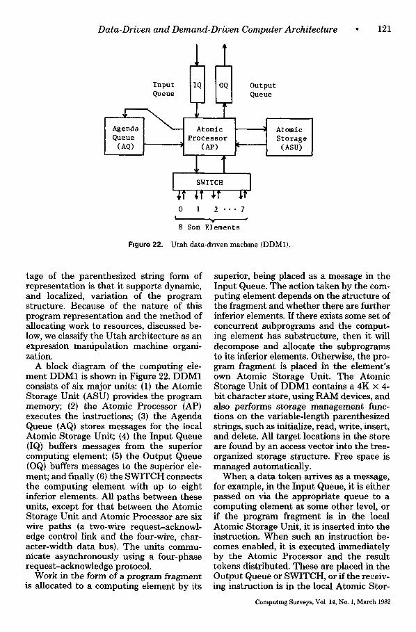
Data-Driven and Demand-Driven Computer Architecture
Input Queue
[%, I
i
EIII Atomic
Processor (AP)
~T ~T ir tt 0 1 2 - . - 7
I ,
8 Son E~ements
Output Queue
Atomic I Storage (ASU)
F,gure 22. U tah data-driven machine (DDM1).
• 1 2 1
tage of the parenthesized string form of representation is that it supports dynamic, and localized, variation of the program structure. Because of the nature of this program representation and the method of allocating work to resources, discussed be- low, we classify the Utah architecture as an expression manipulation machine organi- zation.
A block diagram of the computing ele- ment DDM1 is shown in Figure 22. DDM1 consists of six major units: (1) the Atomic Storage Unit (ASU) provides the program memory; (2) the Atomic Processor (AP} executes the instructions; (3) the Agenda Queue (AQ) stores messages for the local Atomic Storage Unit; (4) the Input Queue (IQ) buffers messages from the superior computing element; (5) the Output Queue (OQ) buffers messages to the superior ele- ment; and finally (6) the SWITCH connects the computing element with up to eight inferior elements. All paths between these units, except for that between the Atomic Storage Unit and Atomic Processor are six wire paths (a two-wire request-acknowl- edge control link and the four-wire, char- acter-width data bus}. The units commu- nicate asynchronously using a four-phase request-acknowledge protocol.
Work in the form of a program fragment is allocated to a computing element by its
superior, being placed as a message in the Input Queue. The action taken by the com- puting element depends on the structure of the fragment and whether there are further inferior elements. If there exists some set of concurrent subprograms and the comput- ing element has substructure, then it will decompose and allocate the subprograms to its inferior elements. Otherwise, the pro- gram fragment is placed in the element's own Atomic Storage Unit. The Atomic Storage Unit of DDM1 contains a 4K × 4- bit character store, using RAM devices, and also performs storage management func- tions on the variable-length parenthesized strings, such as initialize, read, write, insert, and delete. All target locations in the store are found by an access vector into the tree- organized storage structure. Free space is managed automatically.
When a data token arrives as a message, for example, in the Input Queue, it is either passed on via the appropriate queue to a computing element at some other level, or if the program fragment is in the local Atomic Storage Unit, it is inserted into the instruction. When such an instruction be- comes enabled, it is executed immediately by the Atomic Processor and the result tokens distributed. These are placed in the Output Queue or SWITCH, or if the receiv- ing instruction is in the local Atomic Stor-
Computing Surveys, Vol 14, No. 1, March 1982
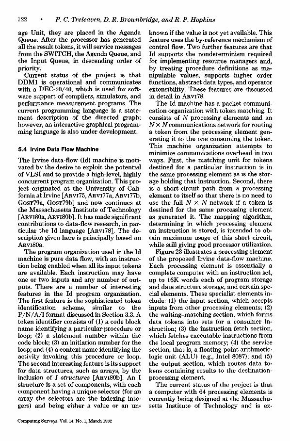
122 • P. C. Treleaven, D. R. Brownbridge, and R. P. Hopkins
age Unit, they are placed in the Agenda Queue. After the processor has generated all the result tokens, it will service messages from the SWITCH, the Agenda Queue, and the Input Queue, in descending order of priority.
Current status of the project is that DDM1 is operational and communicates with a DEC-20/40, which is used for soft- ware support of compilers, simulators, and performance measurement programs. The current programming language is a state- ment description of the directed graph; however, an interactive graphical program- ming language is also under development.
5.4 Irvine Data Flow Machine
The Irvine data-flow (Id) machine is moti- vated by the desire to exploit the potential of VLSI and to provide a high-level, highly concurrent program organization. This pro- ject originated at the University of Cali- fornia at Irvine [ARvI75, ARVI77a, ARVI77b, GOST79a, GOST79b] and now continues at the Massachusetts Institute of Technology [ARvI80a, ARvI80b]. It has made significant contributions to data-flow research, in par- ticular the Id language [ARVI78]. The de- scription given here is principally based on ARVI80a.
The program organization used in the Id machine is pure data flow, with an instruc- tion being enabled when all its input tokens are available. Each instruction may have one or two inputs and any number of out- puts. There are a number of interesting features in the Id program organization. The first feature is the sophisticated token identification scheme, similar to the P / N / A / I format discussed in Section 3.3. A token identifier consists of (1) a code block name identifying a particular-procedure or loop; (2) a statement number within the code block; (3) an initiation number for the loop; and (4) a context name identifying the activity invoking this procedure or loop. The second interesting feature is its support for data structures, such as arrays, by the inclusion of I structures [ARvI80b]. An I structure is a set of components, with each component having a unique selector (for an array the selectors are the indexing inte- gers) and being either a value or an un-
known if the value is not yet available. This feature uses the by-reference mechanism of control flow. Two further features are that Id supports the nondeterminism required for implementing resource managers and, by treating procedure definitions as ma- nipulable values, supports higher order functions, abstract data types, and operator extensibility. These features are discussed in detail in ARVI78.
The Id machine has a packet communi- cation organization with token matching. It consists of N processing elements and an N × N communications network for routing a token from the processing element gen- erating it to the one consuming the token. This machine organization attempts to minimize communications overhead in two ways. First, the matching unit for tokens destined for a particular instruction is in the same processing element as is the stor- age holding that instruction. Second, there is a short-circuit path from a processing element to itself so that there is no need to use the full N × N network if a token is destined for the same processing element as generated it. The mapping algorithm, determining in which processing element an instruction is stored, is intended to ob- tain maximum usage of this short circuit, while still giving good processor utilization.
Figure 23 illustrates a processing element of the proposed Irvine data-flow machine. Each processing element is essentially a complete computer with an instruction set, up to 16K words each of program storage and data structure storage, and certain spe- cial elements. These specialist elements in- clude: (1) the input section, which accepts inputs from other processing elements; (2) the waiting-matching section, which forms data tokens into sets for a consumer in- struction; (3) the instruction fetch section, which fetches executable instructions from the local program memory; (4) the service section, that is, a floating-point arithmetic- logic unit (ALU) (e.g., Intel 8087); and (5) the output section, which routes data to- kens containing results to the destination- processing element.
The current status of the project is that a computer with 64 processing elements is currently being designed at the Massachu- setts Institute of Technology and is ex-
Computing Surveys, Vol. 14, No. 1, March 1982
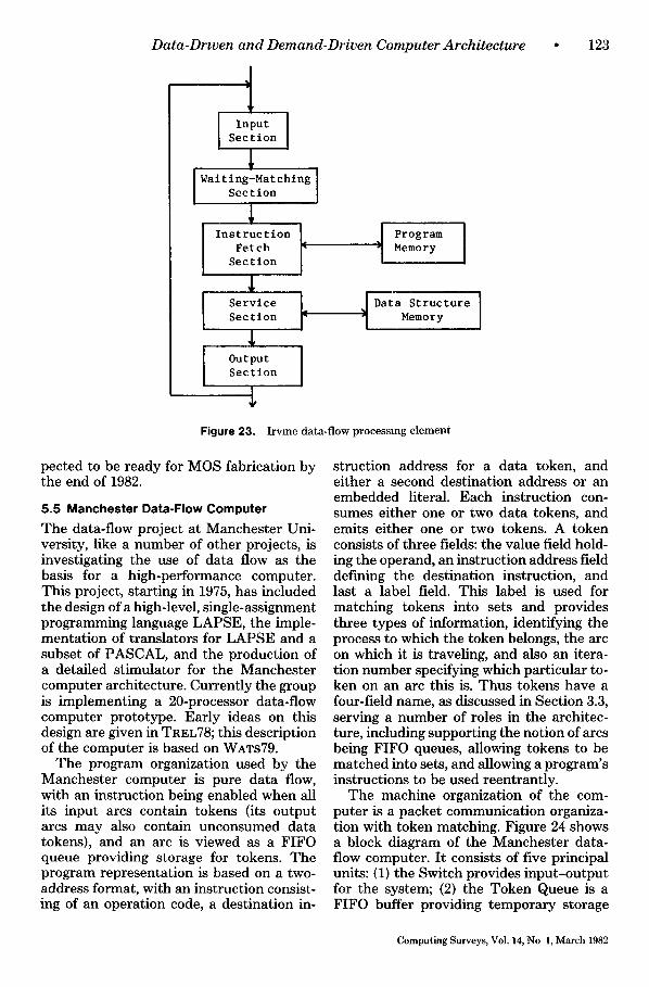
Data-Drwen and Demand-Driven Computer Architecture
i n.u' I Section
Walt ing-Mat chlng Section
L Instruction Fetch Section
Service Section
Output ] Section
I Program Memory
DataMemoryStructure ]
123
Figure 23. Irvme data-flow processing element
pected to be ready for MOS fabrication by the end of 1982.
5.5 Manchester Data-Flow Computer
The data-flow project at Manchester Uni- versity, like a number of other projects, is investigating the use of data flow as the basis for a high-performance computer. This project, starting in 1975, has included the design of a high-level, single-assignment programming language LAPSE, the imple- mentation of translators for LAPSE and a subset of PASCAL, and the production of a detailed stimulator for the Manchester computer architecture. Currently the group is implementing a 20-processor data-flow computer prototype. Early ideas on this design are given in TREL78; this description of the computer is based on WATS79.
The program organization used by the Manchester computer is pure data flow, with an instruction being enabled when all its input arcs contain tokens (its output arcs may also contain unconsumed data tokens), and an arc is viewed as a FIFO queue providing storage for tokens. The program representation is based on a two- address format, with an instruction consist- ing of an operation code, a destination in-
struction address for a data token, and either a second destination address or an embedded literal. Each instruction con- sumes either one or two data tokens, and emits either one or two tokens. A token consists of three fields: the value field hold- ing the operand, an instruction address field defining the destination instruction, and last a label field. This label is used for matching tokens into sets and provides three types of information, identifying the process to which the token belongs, the arc on which it is traveling, and also an itera- tion number specifying which particular to- ken on an arc this is. Thus tokens have a four-field name, as discussed in Section 3.3, serving a number of roles in the architec- ture, including supporting the notion of arcs being FIFO queues, allowing tokens to be matched into sets, and allowing a program's instructions to be used reentrantly.
The machine organization of the com- puter is a packet communication organiza- tion with token matching. Figure 24 shows a block diagram of the Manchester data- flow computer. It consists of five principal units: (1) the Switch provides input-output for the system; (2) the Token Queue is a FIFO buffer providing temporary storage
Computing Surveys, Vol. 14, No l, March 1982
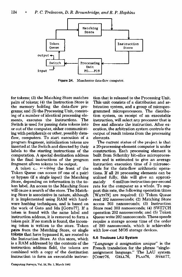
124 P. C. Treleaven, D. R. Brownbridge, and R. P. Hopkins
J Hatching i 1 ,:ore 1
I Instruction Store
Token [ Queue
output~ I [
Processing Unit
PO...P19
Figure 24. Manchester data-flow computer.
for tokens; (3) the Matching Store matches pairs of tokens; (4) the Instruction Store is the memory holding the data-flow pro- grams; and (5) the Processing Unit, consist- ing of a number of identical processing ele- ments, executes the instructions. The Switch is used for passing data tokens into or out of the computer, either communicat- ing with peripherals or other, possibly data- flow, computers. To start execution of a program fragment, initialization tokens are inserted at the Switch and directed by their labels to the starting instructions of the computation. A special destination address in the final instructions of the program fragment allows tokens to be output.
A token ~.. r~-~cb~ng the front of the Token Queue can access (if one of a pair) or bypass (if a single input) the Matching Store, depending on information in the to- ken label. An access to the Matching Store will cause a search of the store. The Match- ing Store is associative in nature, although it is implemented using RAM with hard- ware hashing techniques, and is based on the work of Goto and Ida [GOTo77]. If a token is found with the same label and instruction address, it is removed to form a token pair. If no match is found, the incom- ing token is written to the store. Token pairs from the Matching Store, or single tokens that have bypassed it, are routed to the Instruction Store. At this store, which is a RAM addressed by the contents of the instruction address field, the tokens are combined with a copy of the destination instruction to form an executable instruc-
Computing Surveys, Vol. 14, No. 1, March 1982
tion that is released to the Processing Unit. This unit consists of a distribution and ar- bitration system, and a group of micropro- grammed microprocessors. The distribu- tion system, on receipt of an executable instruction, will select any processor that is free and allocate the instruction. After ex- ecution, the arbitration system controls the output of result tokens from the processing elements.
The current status of the project is that a 20-processing-element computer is under construction. Each processing element is built from Schottky bit-slice microproces- sors and is estimated to give an average instruction execution time of 3 microsec- onds for the data-flow arithmetic opera- tions. If all 20 processing elements can be utilized fully, this will give an approxi- mately 6-million-instruction-per-second rate for the computer as a whole. To sup- port this rate, the following operation times [WATS79] are required: (1) Token Queue read 202 nanoseconds; (2) Matching Store access 303 nanoseconds; (3) Instruction Store read 303 nanoseconds; (4) SWITCH operation 202 nanoseconds; and (5) Token Queue write 202 nanoseconds. These speeds require a storage access time of the order of 200 nanoseconds, which is achievable with low-cost MOS storage devices.
5.6 Toulouse LAU System
"Language d assignation unique" is the French translation for the phrase "single- assignment language." The LAU system [CoMT76, GELL76, PLAS76, S¥RE77,
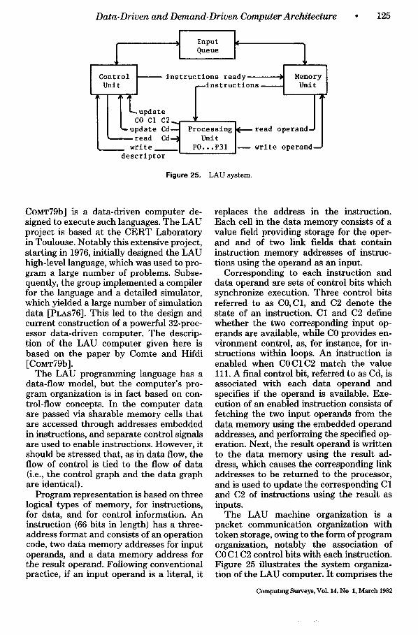
Data-Driven and Demand-Driven Computer Architecture
Input I Queue 1
Control [. instructions ready 1 Memory Unit ~Instructlons Unit
k::::::::::! Processing Unit e ° PO...P31
descriptor
Figure 25. LAU system.
• 125
COMT79b] is a data-driven computer de- signed to execute such languages. The LAU project is based at the CERT Laboratory in Toulouse. Notably this extensive project, starting in 1976, initially designed the LAU high-level language, which was used to pro- gram a large number of problems. Subse- quently, the group implemented a compiler for the language and a detailed simulator, which yielded a large number of simulation data [PLAs76]. This led to the design and current construction of a powerful 32-proc- essor data-driven computer. The descrip- tion of the LAU computer given here is based on the paper by Comte and Hifdi [CoMT79b].
The LAU programming language has a data-flow model, but the computer's pro- gram organization is in fact based on con- trol-flow concepts. In the computer data are passed via sharable memory cells that are accessed through addresses embedded in instructions, and separate control signals are used to enable instructions. However, it should be stressed that, as in data flow, the flow of control is tied to the flow of data (i.e., the control graph and the data graph are identical).
Program representation is based on three logical types of memory, for instructions, for data, and for control information. An instruction (66 bits in length) has a three- address format and consists of an operation code, two data memory addresses for input operands, and a data memory address for the result operand. Following conventional practice, if an input operand is a literal, it
replaces the address in the instruction. Each cell in the data memory consists of a value field providing storage for the oper- and and of two link fields that contain instruction memory addresses of instruc- tions using the operand as an input.
Corresponding to each instruction and data operand are sets of control bits which synchronize execution. Three control bits referred to as C0,C1, and C2 denote the state of an instruction. C1 and C2 define whether the two corresponding input op- erands are available, while CO provides en- vironment control, as, for instance, for in- structions within loops. An instruction is enabled when COC1C2 match the value 111. A final control bit, referred to as Cd, is associated with each data operand and specifies if the operand is available. Exe- cution of an enabled instruction consists of fetching the two input operands from the data memory using the embedded operand addresses, and performing the specified op- eration. Next, the result operand is written to the data memory using the result ad- dress, which causes the corresponding link addresses to be returned to the processor, and is used to update the corresponding C1 and C2 of instructions using the result as inputs.
The LAU machine organization is a packet communication organization with token storage, owing to the form of program organization, notably the association of CO C1 C2 control bits with each instruction. Figure 25 illustrates the system organiza- tion of the LAU computer. It comprises the
Computmg Surveys, Vol. 14, No 1, March 1982
126 • P. C. Treleaven, D. R. Brownbridge, and R. P. Hopkins
memory unit providing storage for instruc- tions and data, the control unit maintaining the control memory, and the processing unit consisting of 32 identical processing elements. Each element is a 16-bit micro- programmed processor built around the AMD 2900 bit-slice microprocessor. Per- haps the most interesting part is the control unit, where the von Neumann program counter is replaced by two memories: the Instruction Control Memory (ICM) and the Data Control Memory (DCM). ICM han- dles the three control bits CO C1 C2 associ- ated with each instruction and DCM man- ages the Cd bit associated with each data operand.
As an illustration of the operation of the LAU computer let us consider the process- ing of an enabled instruction. Processing starts in the control unit at the Instruction Control Memory. ICM is composed of 32K three-bit-wide words, with the control bits in word i corresponding to the instruction in word i in the memory unit. Two proces- sors scan this memory: the Update Pro- cessor sets particular bits of CO C1 C2, and the Instruction Fetch Processor associa- tively accesses the memory for 111 pat- terns. When an enabled instruction is found, its address is sent to the memory unit and the control bits are reset to 011.
The address of the enabled instruction is queued, if necessary, in a 16-bit × 64-word FIFO queue, which is a pool of work for the memory unit. This unit consumes the ad- dress and places the corresponding instruc- tion on the instruction bus, which is also a 64-bit × 128-word FIFO queue, where it is eventually accessed by an idle processing element. Once in a processing element, the instructioff is decoded and the input ad- dresses are dispatched to the memory unit to access the data operands. When the in- puts return, the operation is performed and the result generated. Next the processing element issues a write-read request to the memory unit giving the result and its ad- dress. The result will be stored in the value field and the contents of the two link fields will be returned to the element. Once the link fields have been returned, the process- ing element sends the links to the Update Processor, which uses them to set the cor- responding C1 or C2 bits in the instruction
control memory. In parallel to the storing of the result, the processing element sends the result address to the data control mem- ory where the Cd bit is set. This memory is n 1-bit words. Like the ICM, the DCM is served by two processors, one that updates the Cd bits and the other that checks that accesses to operands in the memory unit are in fact available (i.e., the Cd bit is set).
Regarding the status of the LAU project, the first of the 32 processors became oper- ational in September 1979, and the remain- der have been constructed since then. Pre- dicted performance figures for this hard- ware are given in COMT79b.
5.7 Newcastle Data-Control Flow Computer
Most of the data-driven projects discussed above are based on a single program orga- nization and are concerned, specifically, with studying its embodiment in a suitable machine organization. In contrast, the group at the University of Newcastle upon Tyne are interested in the actual program organizations, their suitability for a general- purpose decentralized computer, and the possibilities for combining them. In this respect the group has investigated, using software and hardware simulators, data flow [TREL78], "multithread" control flow [FARR79], and reduction [TREL80a] orga- nizations, and also combinations of more than one organization in a single computer. Here we describe the JUMBO computer architecture [HoPK79, TREL82] built to study the integration of data-flow and con- trol-flow computation.
The program organization has both data tokens and control tokens, and some spe- cific combination of tokens causes the en- abling of a particular instruction. In the organization there are two ways in which an instruction may obtain its input oper- ands, namely, (1) by receiving data tokens, which may carry a value or an address of the stored value; or (2) by means of embed- ded inputs stored in the instruction, which, like the contents of data tokens, may be literal values or addresses. When an in- struction is enabled, the token inputs and embedded inputs are merged to produce a set of values and addresses. The addresses of inputs are then dereferenced and re-
Computing Surveys, Vol. 14, No. 1, March 1982
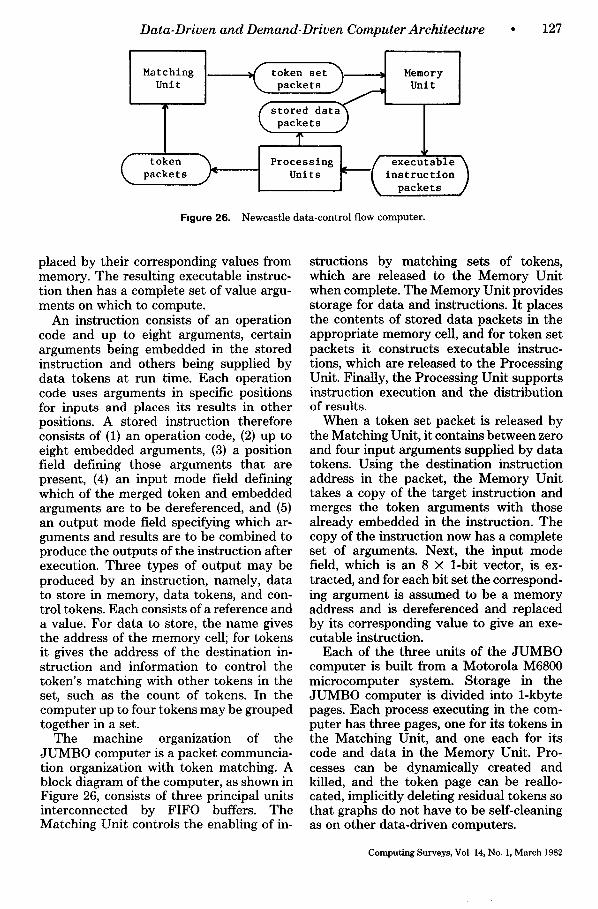
Data-Driven and Demand-Driven Computer Architecture
Matching Unit
T token packets
I ----------~ token set~-~ Memory k , ~ packets j ] ~ Unit
( s t o r e d da t a~ ~.~ packets j ]
T Processlng ~(executable)
Units instruction packets
Figure 26. Newcastle data-control flow computer.
* 1 2 7
placed by their corresponding values from memory. The resulting executable instruc- tion then has a complete set of value argu- ments on which to compute.
An instruction consists of an operation code and up to eight arguments, certain arguments being embedded in the stored instruction and others being supplied by data tokens at run time. Each operation code uses arguments in specific positions for inputs and places its results in other positions. A stored instruction therefore consists of (1) an operation code, (2) up to eight embedded arguments, (3) a position field defining those arguments that are present, (4) an input mode field defining which of the merged token and embedded arguments are to be dereferenced, and (5) an output mode field specifying which ar- guments and results are to be combined to produce the outputs of the instruction after execution. Three types of output may be produced by an instruction, namely, data to store in memory, data tokens, and con- trol tokens. Each consists of a reference and a value. For data to store, the name gives the address of the memory cell; for tokens it gives the address of the destination in- struction and information to control the token's matching with other tokens in the set, such as the count of tokens. In the computer up to four tokens may be grouped together in a set.
The machine organization of the JUMBO computer is a packet communcia- tion organization with token matching. A block diagram of the computer, as shown in Figure 26, consists of three principal units interconnected by FIFO buffers. The Matching Unit controls the enabling of in-
structions by matching sets of tokens, which are released to the Memory Unit when complete. The Memory Unit provides storage for data and instructions. It places the contents of stored data packets in the appropriate memory cell, and for token set packets it constructs executable instruc- tions, which are released to the Processing Unit. Finally, the Processing Unit supports instruction execution and the distribution of results.
When a token set packet is released by the Matching Unit, it contains between zero and four input arguments supplied by data tokens. Using the destination instruction address in the packet, the Memory Unit takes a copy of the target instruction and merges the token arguments with those already embedded in the instruction. The copy of the instruction now has a complete set of arguments. Next, the input mode field, which is an 8 × 1-bit vector, is ex- tracted, and for each bit set the correspond- ing argument is assumed to be a memory address and is dereferenced and replaced by its corresponding value to give an exe- cutable instruction.
Each of the three units of the JUMBO computer is built from a Motorola M6800 microcomputer system. Storage in the JUMBO computer is divided into 1-kbyte pages. Each process executing in the com- puter has three pages, one for its tokens in the Matching Unit, and one each for its code and data in the Memory Unit. Pro- cesses can be dynamically created and killed, and the token page can be reallo- cated, implicitly deleting residual tokens so that graphs do not have to be self-cleaning as on other data-driven computers.
Computing Surveys, Vol 14, No. 1, March 1982
128 • P . (7. Treleaven, D. R. Brownbridge, and R. P. Hopkins
5.8 Other Projects
Research into data flow is a rapidly expand- ing area in the United States, Japan, and Europe. Besides the projects briefly de- scribed above, there are a number of other interesting data-flow projects worthy of de- scription in this survey. These include: the MAUD single-assignment system at the University of Lille, France [LEco79]; work at the Mathematical Center, Amster- dam on compiling conventional languages for data-flow machines [VEEN80]; the PLEXUS project at the University of Tampere, Finland JERK180]; the FLO pro- ject at the University of Manchester, Eng- land [EGAN79]; work on a hierarchical data- flow system at the Clarkson Coll~ge of Technology, New York [SHRO77]; and a number of machines that have been built or are under development in Japan [JIPD81b] such as a high-speed, data-flow machine being developed at Nippon Tele- graph and Telephone [AMAM80, JIPD81b].
6. REDUCTION COMPUTERS
Apart from the pioneering work of Klaus Berkling, the stage of development of re- duction computers somewhat lags behind that of data-flow computers. This is prob- ably due to reduction semantics being an unfamiliar form of program execution for most computer architects.
6.1 GMD Reduction Machine
The reduction machine project based on the GMD (Gesellschaft fur Mathematik und Datenverarbeitung) Laboratory in Bonn, West Germany, aimed to demon- strate that reduction machines are a prac- tical alternative to conventional architec- tures. In particular, the aim was to build a computer easy to program directly in a high-level, functional language based on the lambda calculus. Early ideas on this theme are given in BERK71 and consolidated in BERK75. This description of the GMD re- duction machine is based on the account in KLUG79, supplemented by information from HOMM79 and KLUG80.
The GMD machine's program organiza- tion is string reduction. A design objective was the elimination of addresses entirely, and this is achieved by always using substi-
Computing Surveys, Vol 14, No 1, March 1982
tution copies of code and data instead of sharing by using addresses. In the machine a program is represented as a prefix expres- sion, the binary tree structuring being uniquely exhibited by a string of symbols. These expressions may be atoms--single symbols or values--or may themselves be strings. Each subtree consists of three parts, namely, a constructor, a function, and its argument.
One task of the constructor is to indicate which of its offspring in the tree is the function and which the argument. Since the reduction machine is designed to traverse expression trees in preorder (i.e., left sub- tree before the right), it is necessary to know whether the function or the argument should be reduced first, and the order in which they occur in the expression. This is provided by two types of constructor rep- resented by the symbols ":" and "(--." The constructor ":", used in the format ": argu- ment function", evaluates the argument expression, by reduction to a constant expression, before the function is applied to it. The constructor "~-", used in the form "(-- function argument", applies (reduces) the function expression before the argu- ment is evaluated.
Expressions may in general be built from either constructor and identical constant expressions obtained. For instance, the arithmetic expression 4 + 2 can be repre- sented either as : 2 : 4 + or as (-- (-- + 4 2. Dif- ferences arise when constructors are ap- plied to function bodies as they give rise to by-value and by-name parameter substitu- tion. Special symbols for function-argu- ment binding are also provided in the form of a pair of constructors lambda and alpha. The former implements standard lambda substitution, while the latter is used to im- plement recursion. Lambda simply causes the actual parameter to be substituted for a formal parameter in an expression (the operation being known in lambda calculus as a beta reduction). Alpha is used to bind function bodies to occurrences of the func- tion name in recursive expressions, with occurrences of the name being replaced by a new application of alpha, for example,
ALPHA.f{. . . f . . . ) reduces to f ( . . . ALPHA.f . . . )
Obviously the bracketed body of f must
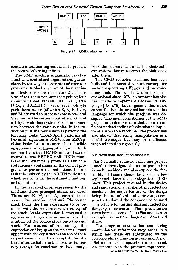
Data-Driven and Demand-Driven Computer Architecture
INPUT/ OUTPUT
Figure 27. G M D reduct ion machine .
• 1 2 9
contain a terminating condition to prevent the recursion's being infinite.
The GMD machine organization is clas- sified as a centralized organization, partic- ularly by the way it represents and executes programs. A block diagram of the machine architecture is shown in Figure 27. It con- sists of the reduction unit (comprising four subunits named TRANS, REDREC, RE- DEX, and ARITH), a set of seven 4-kbyte push-down stacks (of which E, A, B, U, V, and M are used to process expressions, and S serves as the system control stack), and a 1-byte-wide bus system for communica- tion between the various units. In the re- duction unit the four subunits perform the following tasks. TRANSport performs all traversal algorithms; REDuction-RECog- nition looks for an instance of a reducible expression during traversal and, upon find- ing one, halts the TRANS unit and passes control to the REDEX unit. REDuction- EXecution essentially provides a fast con- trol memory containing all the control pro- grams to perform the reductions. In this task it is assisted by the ARITHmetic unit, which performs all the arithmetic and log- ical operations.
In the traversal of an expression by the machine, three principal stacks are used. These are E, M, and A, referred to as source, intermediate, and sink. The source stack holds the tree expression to be re- duced with the root constructor on top of the stack. As the expression is traversed, a succession of pop operations moves the symbols off the source stack onto the sink stack. For reasons of consistency, the expression ending up on the sink stack must appear with the constructors on top of their respective subtrees. To accomplish this, the third intermediate stack is used as tempo- rary storage for constructors that emerge
from the source stack ahead of their sub- expressions, but must enter the sink stack after them.
The GMD reduction machine has been built and is connected to a microcomputer system supporting a library and program- ming tools. The whole system has been operational since 1978. An attempt has also been made to implement Backus' FP lan- guage [BACK78], but in general this is less successful than the original lambda calculus language for which the machine was de- signed. The main contribution of the GMD project is to demonstrate that there is suf- ficient understanding of reduction to imple- ment a workable machine. The project has also shown that string manipulation is a useful technique but may be inefficient when adhered to rigorously.
6.2 Newcastle Reduction Machine
The Newcastle reduction machine project aimed to investigate the use of parallelism in such machines and also explore the fea- sibility of basing these designs on a few replicated large-scale integrated (LSI) parts. This project resulted in the design and simulation of a parallel string reduction machine, the major feature of the design being the use of state-table-driven proces- sors that allowed the computer to be used as a vehicle for testing different reduction (language) schemes. The presentation given here is based on TREL80a and uses an example reduction language described there.
The program organization uses string manipulation; references may occur in a string, and these are substituted by the corresponding definition at run time. A par- allel innermost computation rule is used. An expression in the program representa-
Computing Surveys, Vol. 14, No 1, March 1982
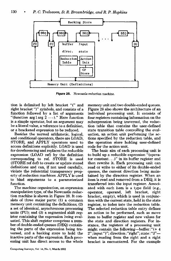
130
! P. C. Treleaven, D. R. Brownbridge, and R. P. Hopkins
L " ~ Backing Store r
dlrec. state
| Memory U n i t ( D e f i n i t i o n s )
Figure 28. Newcast le reduct ion machine .
tion is delimited by left bracket "(" and right bracket ")" symbols, and consists of a function followed by a list of arguments "(function arg 1 arg 2 . . . ) . " Here function is a simple operator, but an argument may be a literal value, a reference to a definition, or a bracketed expression to be reduced.
Besides the normal arithmetic, logical, and conditional operators, there are LOAD, STORE, and APPLY operators used to access definitions explicitly. LOAD is used for dereferencing and replaces the reducible expression (LOAD ref) by the definition corresponding to ref. STORE is used (STORE ref def) to create or update stored definitions and can, if not used carefully, violate the referential transparency prop- erty of reduction machines. APPLY is used to bind arguments to a parameterized function.
The machine organization, an expression manipulation type, of the Newcastle reduc- tion machine is shown in Figure 28. It con- sists of three major parts: (1) a common memory unit containing the definitions; (2) a set of identical, asynchronous processing units (PU); and (3) a segmented shift reg- ister containing the expression being eval- uated. This shift register comprises a num- ber of double-ended queues (DEQ) contain- ing the parts of the expression being tra- versed, and a backing store to hold the inactive parts of the expression. Each proc- essing unit has direct access to the whole
Computing Surveys, Vol 14, No. 1, March 1982
memory unit and two double-ended queues. Figure 28 also shows the architecture of an individual processing unit. It consists of four registers containing information on the subexpression being traversed, the reduc- tion table that contains the user-defined state transition table controlling the eval- uation, an action unit performing the ac- tions specified by the reduction table, and the operation store holding user-defined code for the action unit.
The basic aim of each processing unit is to build up a reducible expression "(opera- tor cons tant . . . ) " in its buffer register and then rewrite it. Each processing unit can read or write to either of its double-ended queues, the current direction being main- tained by the direction register. When an item is read and removed from a DEQ, it is transferred into the input register. Associ- ated with each item is a type field (e.g., operator, operand, left bracket, right bracket, empty), which is used in conjunc- tion with the current state, held in the state register, to index into the reduction table. The selected reduction table entry defines an action to be performed, such as move item to buffer register and new values for the state and direction registers. For in- stance, the registers of a processing unit might contain the following--buffer:"(+ 4 2" ; input")"; direction: "right"; state: "3"-- when reading from the right and a right bracket is encountered. For the example
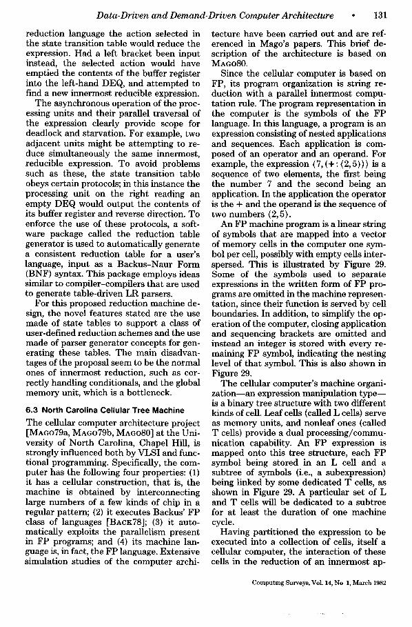
Data-Driven a n d Demand-Dr iven Computer Archi tec ture • 131
reduction language the action selected in the state transition table would reduce the expression. Had a left bracket been input instead, the selected action would have emptied the contents of the buffer register into the left-hand DEQ, and attempted to find a new innermost reducible expression.
The asynchronous operation of the proc- essing units and their parallel traversal of the expression clearly provide scope for deadlock and starvation. For example, two adjacent units might be attempting to re- duce simultaneously the same innermost, reducible expression. To avoid problems such as these, the state transition table obeys certain protocols; in this instance the processing unit on the right reading an empty DEQ would output the contents of its buffer register and reverse direction. To enforce the use of these protocols, a soft- ware package called the reduction table generator is used to automatically generate a consistent reduction table for a user's language, input as a Backus-Naur Form (BNF) syntax. This package employs ideas similar to compiler-compilers that are used to generate table-driven LR parsers.
For this proposed reduction machine de- sign, the novel features stated are the use made of state tables to support a class of user-defined reduction schemes and the use made of parser generator concepts for gen- erating these tables. The main disadvan- tages of the proposal seem to be the normal ones of innermost reduction, such as cor- rectly handling conditionals, and the global memory unit, which is a bottleneck.
6.3 North Carolina Cellular Tree Machine
The cellular computer architecture project [MAGo79a, MAGO79b, MAGO80] at the Uni- versity of North Carolina, Chapel Hill, is strongly influenced both by VLSI and func- tional programming. Specifically, the com- puter has the following four properties: (1) it has a cellular construction, that is, the machine is obtained by interconnecting large numbers of a few kinds of chip in a regular pattern; (2) it executes Backus' FP class of languages [BACK78]; (3) it auto- matically exploits the parallelism present in FP programs; and (4) its machine lan- guage is, in fact, the FP language. Extensive simulation studies of the computer archi-
tecture have been carried out and are ref- erenced in Mago's papers. This brief de- scription of the architecture is based on M A G O 8 0 .
Since the cellular computer is based on FP, its program organization is string re- duction with a parallel innermost compu- tation rule. The program representation in the computer is the symbols of the FP language. In this language, a program is an expression consisting of nested applications and sequences. Each application is com- posed of an operator and an operand. For example, the expression (7, (+ : (2, 5)) ) is a sequence of two elements, the first being the number 7 and the second being an application. In the application the operator is the + and the operand is the sequence of two numbers (2, 5).
An FP machine program is a linear string of symbols that are mapped into a vector of memory cells in the computer one sym- bol per cell, possibly with empty cells inter- spersed. This is illustrated by Figure 29. Some of the symbols used to separate expressions in the written form of FP pro- grams are omitted in the machine represen- tation, since their function is served by cell boundaries. In addition, to simplify the op- eration of the computer, closing application and sequencing brackets are omitted and instead an integer is stored with every re- maining FP symbol, indicating the nesting level of that symbol. This is also shown in Figure 29.
The cellular computer's machine organi- za t ion -an expression manipulation type-- is a binary tree structure with two different kinds of cell. Leaf cells (called L cells) serve as memory units, and nonleaf ones (called T cells) provide a dual processing/commu- nication capability. An FP expression is mapped onto this tree structure, each FP symbol being stored in an L cell and a subtree of symbols (i.e., a subexpression) being linked by some dedicated T cells, as shown in Figure 29. A particular set of L and T cells will be dedicated to a subtree for at least the duration of one machine cycle.
Having partitioned the expression to be executed into a collection of cells, itself a cellular computer, the interaction of these cells in the reduction of an innermost ap-
Computing Surveys, VoL 14, No 1, March 1982
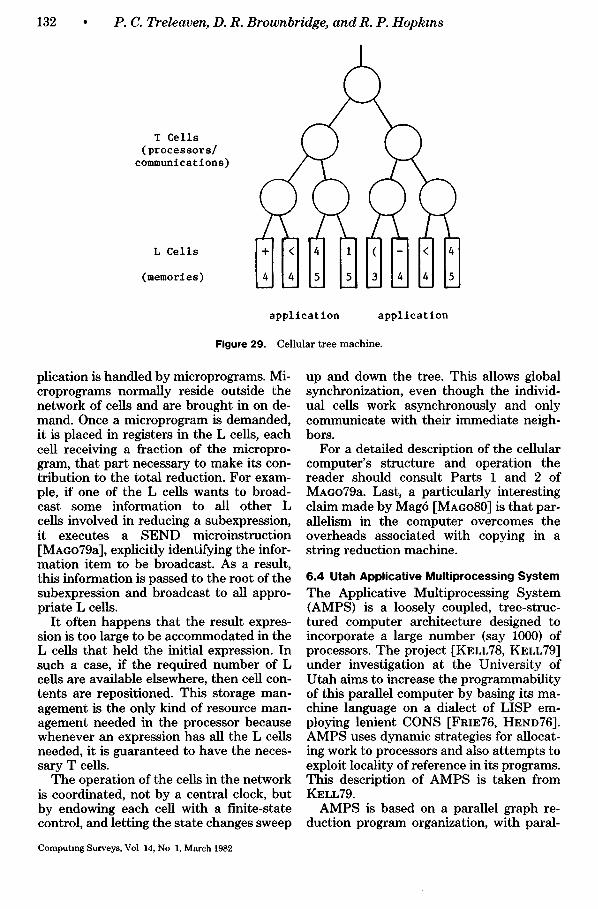
132 • P C. Treleaven, D. R. Brownbridge, and R. P. Hopkins
T Cells (processors/
c o m m u n i c a t i o n s )
L Cells
(memories) i )
application application
Figure 29. Cellular tree machine .
plication is handled by microprograms. Mi- croprograms normally reside outside the network of cells and are brought in on de- mand. Once a microprogram is demanded, it is placed in registers in the L cells, each cell receiving a fraction of the micropro- gram, that part necessary to make its con- tribution to the total reduction. For exam- ple, if one of the L cells wants to broad- cast some information to all other L cells involved in reducing a subexpression, it executes a SEND microinstruction [MAGo79a], explicitly identifying the infor- mation item to be broadcast. As a result, this information is passed to the root of the subexpression and broadcast to all appro- priate L cells.
It often happens that the result expres- sion is too large to be accommodated in the L cells that held the initial expression. In such a case, if the required number of L cells are available elsewhere, then cell con- tents are repositioned. This storage man- agement is the only kind of resource man- agement needed in the processor because whenever an expression has all the L cells needed, it is guaranteed to have the neces- sary T cells.
The operation of the cells in the network is coordinated, not by a central clock, but by endowing each cell with a finite-state control, and letting the state changes sweep
up and down the tree. This allows global synchronization, even though the individ- ual cells work asynchronously and only communicate with their immediate neigh- bors.
For a detailed description of the cellular computer's structure and operation the reader should consult Parts 1 and 2 of MAGO79a. Last, a particularly interesting claim made by Mag6 [MAGO80] is that par- allelism in the computer overcomes the overheads associated with copying in a string reduction machine.
6.4 Utah Applicative Multiprocessing System The Applicative Multiprocessing System (AMPS) is a loosely coupled, tree-struc- tured computer architecture designed to incorporate a large number (say 1000) of processors. The project [KELL78, KELL79] under investigation at the University of Utah aims to increase the programmability of this parallel computer by basing its ma- chine language on a dialect of LISP em- ploying lenient CONS [FreE76, HEND76]. AMPS uses dynamic strategies for allocat- ing work to processors and also attempts to exploit locality of reference in its programs. This description of AMPS is taken from KELL79.
AMPS is based on a parallel graph re- duction program organization, with paral-
Computing Surveys, Vol 14, No 1, March 1982
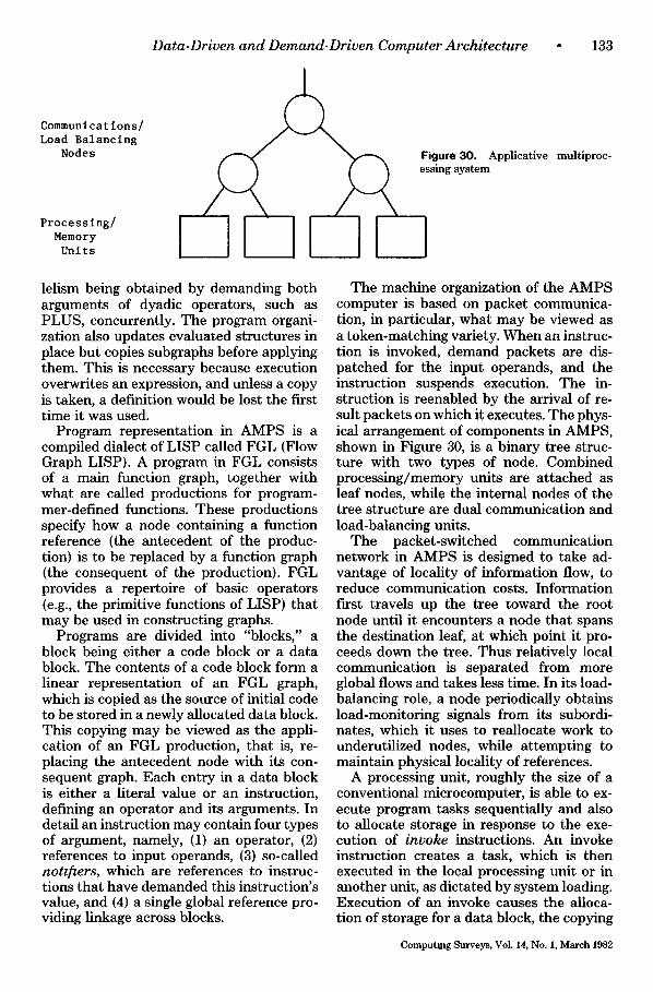
Data-Driven a n d Demand-Dr iven Computer Arch i tec ture • 133
Processing/ Memory Units ILl
Communications/ Load Balancing
Nodes Figure 30. Applicative multiproc- essing system
( m
lelism being obtained by demanding both arguments of dyadic operators, such as PLUS, concurrently. The program organi- zation also updates evaluated structures in place but copies subgraphs before applying them. This is necessary because execution overwrites an expression, and unless a copy is taken, a definition would be lost the first time it was used.
Program representation in AMPS is a compiled dialect of LISP called FGL {Flow Graph LISP). A program in FGL consists of a main function graph, together with what are called productions for program- mer-defined functions. These productions specify how a node containing a function reference (the antecedent of the produc- tion) is to be replaced by a function graph (the consequent of the production). FGL provides a repertoire of basic operators {e.g., the primitive functions of LISP) that may be used in constructing graphs.
Programs are divided into "blocks," a block being either a code block or a data block. The contents of a code block form a linear representation of an FGL graph, which is copied as the source of initial code to be stored in a newly allocated data block. This copying may be viewed as the appli- cation of an FGL production, that is, re- placing the antecedent node with its con- sequent graph. Each entry in a data block is either a literal value or an instruction, defining an operator and its arguments. In detail an instruction may contain four types of argument, namely, (1) an operator, (2) references to input operands, (3) so-called notifiers, which are references to instruc- tions that have demanded this instruction's value, and (4) a single global reference pro- viding linkage across blocks.
The machine organization of the AMPS computer is based on packet communica- tion, in particular, what may be viewed as a token-matching variety. When an instruc- tion is invoked, demand packets are dis- patched for the input operands, and the instruction suspends execution. The in- struction is reenabled by the arrival of re- sult packets on which it executes. The phys- ical arrangement of components in AMPS, shown in Figure 30, is a binary tree struc- ture with two types of node. Combined processing/memory units are attached as leaf nodes, while the internal nodes of the tree structure are dual communication and load-balancing units.
The packet-switched communication network in AMPS is designed to take ad- vantage of locality of information flow, to reduce communication costs. Information first travels up the tree toward the root node until it encounters a node that spans the destination leaf, at which point it pro- ceeds down the tree. Thus relatively local communication is separated from more global flows and takes less time. In its load- balancing role, a node periodically obtains load-monitoring signals from its subordi- nates, which it uses to reallocate work to underutilized nodes, while attempting to maintain physical locality of references.
A processing unit, roughly the size of a conventional microcomputer, is able to ex- ecute program tasks sequentially and also to allocate storage in response to the exe- cution of invoke instructions. An invoke instruction creates a task, which is then executed in the local processing unit or in another unit, as dictated by system loading. Execution of an invoke causes the alloca- tion of storage for a data block, the copying
Computing Surveys, Vol. 14, No. 1, March 1982
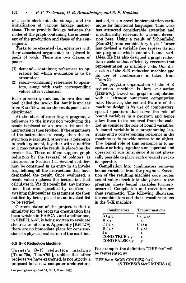
134 • P.C. Treleaven, D. R. Brownbridge, and R. P. Hopkins
of a code block into the storage, and the initialization of various linkage instruc- tions. These provide linkage between the nodes of the graph containing the anteced- ent of the production and those of the con- sequent.
Tasks to be executed (i.e., operators with their associated arguments) are placed in pools of work. There are two classes of pools:
(1) demand--containing references to op- erators for which evaluation is to be attempted;
(2) result--containing references to opera- tors, along with their corresponding values after evaluation.
Each processing unit has its own demand pool, called the invoke list, but it is unclear from KELL79 whether the result pool is also distributed.
At the start of executing a program, a reference to the instruction producing the result is placed on an invoke list and the instruction is then fetched. If the arguments of the instruction are ready, then the in- struction is executed; otherwise, a reference to each argument, together with a notifier so it may return the result, is placed on the invoke list. These notifiers support graph reduction by the reversal of pointers, as discussed in Section 1.4. Several notifiers may be contained in an entry in an invoke list, defining all the instructions that have demanded the result. Once evaluated, a result value replaces the instruction that calculates it. Via the result list, any instruc- tions that were specified by notifiers as awaiting this result as an argument are then notified by being placed on an invoked list to be retried.
Current status of the project is that a simulator for the program organization has been written in PASCAL and another one, in SIMULA-67, is being written to evaluate the tree architecture. Apparently [KELL79] there are no immediate plans for construc- tion of a physical realization of the machine.
6.5 S -K Reduction Machine
T u r n e r ' s S - K r e d u c t i o n m a c h i n e [TuRN79a, TURN79b], unlike the other projects we have examined, is not strictly a proposal for a new computer architecture;
instead, it is a novel implementation tech- nique for functional languages. This work has attracted considerable attention and is sufficiently relevant to warrant discus- sion here. Using a result of Schonfinkel [SCHO24] from combinatory logic, Turner has devised a variable free representation for programs which contain bound vari- ables. He has also designed a graph reduc- tion machine that efficiently executes that representation as machine code. Our dis- cussion of the S-K reduction machine and its use of combinators is taken from TURN79a.
The program organization of the S-K reduction machine is lazy evaluation [HEND76], based on graph manipulation with a leftmost outermost computation rule. However, the central feature of the machine design is its use of combinators, special operators that serve the role of bound variables in a program and hence allow them to be removed from the code. Let us consider the role of bound variables. A bound variable in a programming lan- gnage and a corresponding reference in the machine code provide access to an object. The logical role of this reference is to as- sociate or bring together some operand and operator at run time, since it is not physi- cally possible to place each operand next to its operator.
Compilation into combinators removes bound variables from the program. Execu- tion of the resulting machine code routes actual values back into the places in the program where bound variables formerly occurred. Compilation and execution are thus symmetric. The following illustrates the combinators and their transformations in the S-K machine:
Combinators Transformations
S f g x fx (gx) K x y x C f g x (fx) g B f g x f(gx) Ix x COND TRUE x y x COND FALSE x y y
For example, the definition "DEF fac" will be represented as
DEF fac ffi S(C(B COND(EQ 0))1) (S TIMES(B fac(C MINUS 1))).
Computing Surveys, Vol. 14, No. 1, March 1982
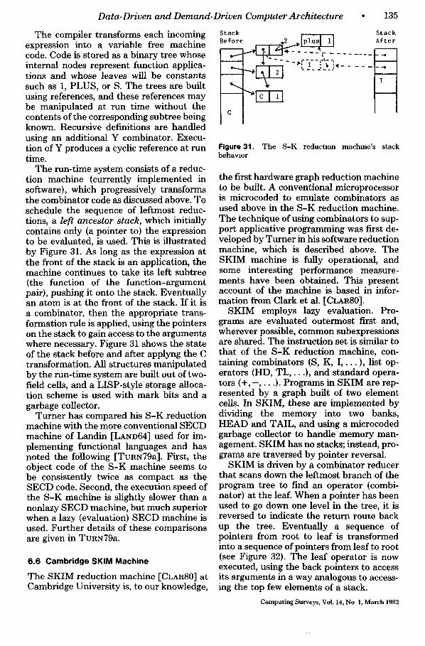
Data-Driven and Demand-Driven Computer Architecture
The compiler transforms each incoming expression into a variable free machine code. Code is stored as a binary tree whose internal nodes represent function applica- tions and whose leaves will be constants such as 1, PLUS, or S. The trees are built using references, and these references may be manipulated at run time without the contents of the corresponding subtree being known. Recursive definitions are handled using an additional Y combinator. Execu- tion of Y produces a cyclic reference at run time.
The run-time system consists of a reduc- tion machine {currently implemented in software), which progressively transforms the combinator code as discussed above. To schedule the sequence of leftmost reduc- tions, a left ancestor stack, which initially contains only (a pointer to) the expression to be evaluated, is used. This is illustrated by Figure 31. As long as the expression at the front of the stack is an application, the machine continues to take its left subtree (the function of the function-argument pair), pushing it onto the stack. Eventually an atom is at the front of the stack. If it is a combinator, then the appropriate trans- formation rule is applied, using the pointers on the stack to gain access to the arguments where necessary. Figure 31 shows the state of the stack before and after applyng the C transformation. All structures manipulated by the run-time system are built out of two- field cells, and a LISP-style storage alloca- tion scheme is used with mark bits and a garbage collector.
Turner has compared his S-K reduction machine with the more conventional SECD machine of Landin [LAND64] used for im- plementing functional languages and has noted the following [TuRN79a]. First, the object code of the S-K machine seems to be consistently twice as compact as the SECD code. Second, the execution speed of the S-K machine is slightly slower than a nonlazy SECD machine, but much superior when a lazy (evaluation) SECD machine is used. Further details of these comparisons are given in TURN79a.
6.6 Cambridge SKIM Machine
The SKIM reduction machine [CLAR80] at Cambridge University is, to our knowledge,
• 1 3 5
Stack Before
Stack
~ ~ S ~ - ~ ] Af t e r
. . . .
Figure 31. The S-K reduction machine's stack behavior
the first hardware graph reduction machine to be built. A conventional microprocessor is microcoded to emulate combinators as used above in the S-K reduction machine. The technique of using combinators to sup- port applicative programming was first de- veloped by Turner in his software reduction machine, which is described above. The SKIM machine is fully operational, and some interesting performance measure- ments have been obtained. This present account of the machine is based in infor- mation from Clark et al. [CLAR80].
SKIM employs lazy evaluation. Pro- grams are evaluated outermost first and, wherever possible, common subexpressions are shared. The instruction set is similar to that of the S-K reduction machine, con- taining combinators (S, K, I . . . . ), list op- erators (HD, TL, . . . ) , and standard opera- tors ( % - , . . . ) . Programs in SKIM are rep- resented by a graph built of two element cells. In SKIM, these are implemented by dividing the memory into two banks, HEAD and TAIL, and using a microcoded garbage collector to handle memory man- agement. SKIM has no stacks; instead, pro- grams are traversed by pointer reversal.
SKIM is driven by a combinator reducer that scans down the leftmost branch of the program tree to find an operator (combi- nator) at the leaf. When a pointer has been used to go down one level in the tree, it is reversed to indicate the return route back up the tree. Eventually a sequence of pointers from root to leaf is transformed into a sequence of pointers from leaf to root (see Figure 32). The leaf operator is now executed, using the back pointers to access its arguments in a way analogous to access- ing the top few elements of a stack.
Computing Surveys, Vol. 14, No 1, March 1982
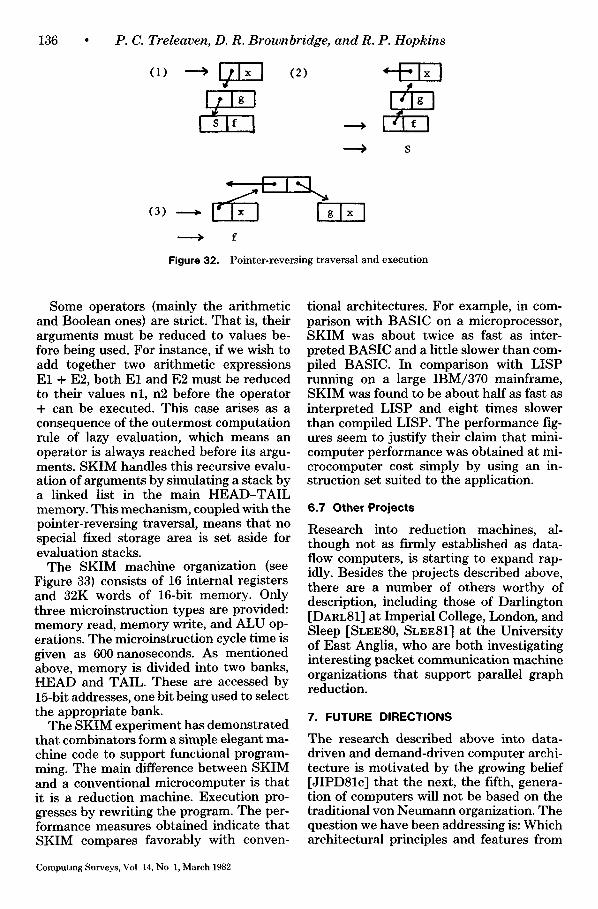
136 P. C. Treleaven, D. R. Brownbridge, and R. P. Hopkins
, (2)
Isl J ) S
(3)
> f
Figure 32. Pointer-reversing traversal and execution
Some operators (mainly the arithmetic and Boolean ones) are strict. That is, their arguments must be reduced to values be- fore being used. For instance, if we wish to add together two arithmetic expressions E1 + E2, both E1 and E2 must be reduced to their values nl, n2 before the operator + can be executed. This case arises as a consequence of the outermost computation rule of lazy evaluation, which means an operator is always reached before its argu- ments. SKIM handles this recursive evalu- ation of arguments by simulating a stack by a linked list in the main HEAD-TAIL memory. This mechanism, coupled with the pointer-reversing traversal, means that no special fixed storage area is set aside for evaluation stacks.
The SKIM machine organization (see Figure 33) consists of 16 internal registers and 32K words of 16-bit memory. Only three microinstruction types are provided: memory read, memory write, and ALU op- erations. The microinstruction cycle time is given as 600 nanoseconds. As mentioned above, memory is divided into two banks, HEAD and TAIL. These are accessed by 15-bit addresses, one bit being used to select the appropriate bank.
The SKIM experiment has demonstrated that combinators form a simple elegant ma- chine code to support functional program- ming. The main difference between SKIM and a conventional microcomputer is that it is a reduction machine. Execution pro- gresses by rewriting the program. The per- formance measures obtained indicate that SKIM compares favorably with conven-
Computing Surveys, Vol 14, No 1, March 1982
tional architectures. For example, in com- parison with BASIC on a microprocessor, SKIM was about twice as fast as inter- preted BASIC and a little slower than com- piled BASIC. In comparison with LISP running on a large IBM/370 mainframe, SKIM was found to be about half as fast as interpreted LISP and eight times slower than compiled LISP. The performance fig- ures seem to justify their claim that mini- computer performance was obtained at mi- crocomputer cost simply by using an in- struction set suited to the application.
6.7 Other Projects
Research into reduction machines, al- though not as firmly established as data- flow computers, is starting to expand rap- idly. Besides the projects described above, there are a number of others worthy of description, including those of Darlington [DARL81] at Imperial College, London, and Sleep [SLEE80, SLEE81] at the University of East Anglia, who are both investigating interesting packet communication machine organizations that support parallel graph reduction.
7. FUTURE DIRECTIONS
The research described above into data- driven and demand-driven computer archi- tecture is motivated by the growing belief [JIPD81c] that the next, the fifth, genera- tion of computers will not be based on the traditional von Neumann organization. The question we have been addressing is: Which architectural principles and features from
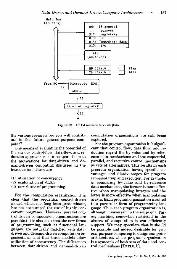
Data-Driven and Demand-Driven Computer Architecture
Main Bus (16 bits)
A i
I I
l
R0: 13 general ... purpose RI2: registers RI3: PC RI4: Immediate data RIS: I/0
ALU [ (4x74S281)
'l HD 16Kx16 I ~ flag TL 16Kx16 bits
from PC: 12/ i MicrOcOde4Kx32 ROM I
[ ' { ipe l ine Regis te ; ' I
t 32
Figure 33. SKIM machme block diagram.
• 1 3 7
the various research projects will contrib- ute to this future general-purpose com- puter?
One means of evaluating the potential of the various control-flow, data-flow, and re- duction approaches is to compare them to the motivations for data-driven and de- mand-driven computing discussed in the introduction. These are
(1) utilization of concurrency; (2) exploitation of VLSI; (3) new forms of programming.
For the computation organization it is clear that the sequential control-driven model, which has long been predominant, has not encouraged the use of highly con- current programs. (However, parallel con- trol-driven computation organizations are possible.) It is also clear that the new forms of programming, such as functional lan- guages, are naturally matched with data- driven and demand-driven computation or- ganizations, and that these models allow utilization of concurrency. The differences between data-driven and demand-driven
computation organizations are still being explored.
For the program organization it is signifi- cant that control flow, data flow, and re- duction regard the by-value and by-refer- ence data mechanisms and the sequential, parallel, and recursive control mechanisms as sets of alternatives. This results in each program organization having specific ad- vantages and disadvantages for program representation and execution. For example, in comparing by-value and by-reference data mechanisms, the former is more effec- tive when manipulating integers and the latter is more effective when manipulating arrays. Each program organization is suited to a particular form of programming lan- guage. Thus each program organization is, although "universal" in the sense of a Tur- ing machine, somewhat restricted in the classes of computation it can efficiently support. We may speculate that it should be possible and indeed desirable for gen- eral-purpose computing to design computer architectures whose program organization is a synthesis of both sets of data and con- trol mechanisms [TREL81b].
Computing Surveys, Vol 14, No 1, March 1982
138 • P.C. Treleaven, D. R. Brownbridge, and R. P. Hopkins
For the machine organization it is clear that centralized, packet communication, and expression manipulation gravitate to- ward, respectively, control flow, data flow, and reduction. However, we have shown that other pairings of the machine organi- zations and the program organizations are viable. When evaluating the three machine organizations against the motivations for data-driven and demand-driven computers listed above, the utilization of concurrency would seem to preclude centralized organi- zations in favor of the other two organiza- tions. In addition, VLSI requires an orga- nization in which a replication of identical computing elements can be plugged to- gether to form a larger parallel computer. But it is also necessary for a computing element to have a centralized organization so that it can function independently. Thus the three machine organizations, instead of being competitive, seem in fact to be com- plementary organizations. Each organiza- tion is based on a sequential building block: a computing element containing a proces- sor, communications, and memory. The centralized organization defines how a sin- gle computing element must be able to function as a self-contained computer. The packet communication organization shows how concurrency within a computing ele- ment may be increased by replicating re- sources. Last, the expression manipulation organization specifies how a group of com- puting elements may be interconnected, at a system level, to satisfy the VLSI attri- butes of replication.
In conclusion, having examined the com- putation organizations, program organiza- tions, and machine organizations for control flow, data flow, and reduction, and also the approaches taken by the individual re- search groups, it is regrettably impossible at this time to identify the future "yon Neumann." We were, however, able to an- alyze the advantages and disadvantages of the various approaches. Using such knowl- edge it is even possible to "engineer" new program organizations and machine orga- nizations [WILN80 , TREL81a].
ACKNOWLEDGMENTS
In acknowledging all the people who have contributed to the writing of this paper it is difficult not to list a significant proportion of the computing science com- munity. First, let us thank those people investigating data-driven and demand-driven computing, whose work was discussed above, for taking tLme to read this document and comment on our description of their work Second, we express our gratitude to Klaus Ber- kling, Jean-Pierre Banatra, A1 Davis, Honan Sleep, and Graham Wood for their detailed comments on an early version of this paper. Third, we would like to thank our colleagues at the University of Newcastle upon Tyne, in particular, current and past members of the Computer Architecture Group. Fourth, we thank the referees for their helpful comments. Finally, we wish to thank the Distributed Computing Systems Panel (its current and past members) of the United Kingdom Science and Engineering Research Council, which not only funds our research but has also been largely responsible for estabhshmg and encouraging data-driven and demand-driven computing research in the Umted Kingdom.
ACKE79a
ACKE79h
AMAM80
ARVI75
ARvi77a
ARvI77b
REFERENCES
ACKERMAN, W. B. "Data flow lan- guages," in Proc. 1979 Nat. Computer Conf. (New York, N.Y., June 4-7), vol. 48, AFIPS Press, Arlington, Va, 1979, pp. 1087-1095. ACKERMAN, W B., AND DENNIS, J. B. "VAL--A value oriented algo- rithmic language, preliminary reference manual," Tech. Rep. TR-218, Lab. for Computer Science, Massachusetts Insti- tute of Technology, June 1979. AMAMIYA, M., HASEGAWA, R., AND MI- KAMI, H. "List processing and data flow machine," Lecture Note Series, No. 436, Research Institute for Mathematical Sciences, Kyoto Unw., Sept 1980. ARVIND AND GOSTELOW, K.P. "A new interpreter for dataflow and its implica- tions for computer architecture," Tech. Rep. 72, Dep Information and Computer Science, Univ. of California, Irvme, Oct. 1975. AEVIND AND GOSTELOW, K. P. "A computer capable of exchanging proces- sors for time," m Proc IFIP Congress (1977), 849-854. ARVIND AND GOSTELOW, K P. "Some relationships between asynchronous in- terpreters of a dataflow language," in Proc. IFIP Working Conf. Formal De- scription of Programming Languages
Computing Surveys, Vol 14, No. 1, March 1982
ARVI78
ARvI80a
AavI80b
ASHC77
BACK72
BACK73
BACK78
BERK71
BERK75
CHAM71
CLARS0
COMT76
Data-Driven and Demand-Driven Computer Archi tecture • 139
(Aug. 1977), E. J. Neuhold, Ed., Elsevier North-Holland, New York, 1977. ARVIND, GOSTELOW, K. P., AND PLOUFFE, W. "An asynchronous programming language and computing machine," Tech. Re/). 114a, Dep. Information and Computer Scmnce, Univ. of California, CORN79 Irvme, Dec. 1978. ARVIND, KATHAIL, V., AND PINGALI, K. "A processing element for a large multiprocessor dataflow machine," in Proc. Int. Conf Cwcmts and Computers (New York, Oct. 1980), IEEE, New York, DARL81 1980. ARVIND AND THOMAS, R E. "I-struc- tures: An efficient data type for func- tional languages," Rep. LCS/TM-178, Lab. for Computer Science, Massachu- setts Institute of Technology, June 1980. ASHCROFT, E. A, AND WADGE, W. W "LUCID, a nonprocedural language DAV178 with iteration," Commun. ACM 20, 7 (July 1977), 519-526 BACKUS, J. "Reductmn languages and variable free programming," Rep. RJ 1010, IBM Thomas J Watson Research Center, Yorktown Heights, N Y., Apr. 1972. BACKUS, J. "Programming languages and closed applicative languages," m Proc. ACM Symp Principles of Pro- grammmg Languages, ACM, New York, 1973, pp 71-86. BACKUS, J. "Can programming be lib- erated from the von Neumann style 9 A functional style and its algebra of pro- grams," Commun. ACM 21, 8 (Aug. DENN71 1978), 613-641. BERKLING, K. J. "A computing ma- chine based on tree structures," IEEE Trans. Comput. C-20, 4 (Jan 1971), 404-
418. DENN72 BERKLING, K. "Reductmn languages for reduction machines," in Proc. 2rid Int. Symp Computer Architecture (Houston, Tex., Jan. 1975), IEEE, New York, 1975, pp. 133-140. CHAMBERLIN, D. D. "The single as- signment approach to parallel process- rag," in Proc Nat. Computer Conf. (Las Vegas, Nev., Nov. 16-18), vol. 39, AFIPS Press, Arlington, Va., 1971, pp. 263-269. CLARKE, T. J. W., GLADSTONE, P. J S , MACLEAN, C. D., AND NORMAN, A. C. "SKIM--The S, K, I reduction ma- chine," in Proc. LISP-80 Conf. (Stan- ford, Calif., Aug. 1980), pp. 128-135 COMTE, D., DURRIEU, A., GELLY, O., PLAS, A., AND SYRE, J C. "TEAU 9/7: SYSTEME LAU--Summary m Eng- lish," CERT Tech. Rep. #1/3059, Centre d'l~tudes et de Recherches de Toulouse, Oct. 1976.
COMT79b
DAV179a
DAV179b
DENN 74a
DENN 74b
DENN75b
COMTE, D., AND HIFDI, N. "LAU Mul- tiprocessor. Microfunctional description and technological choices," in Proc. 1st European Conf. Parallel and D~str~b- uted Processing (Toulouse, France, Feb. 1979), pp. 8-15. CORNISH, M. "The TI data flow archi- tectures: The power of concurrency for avionics," in Proc. 3rd Conf. Digital Avlonws Systems {Fort Worth, Tex., Nov. 1979), IEEE, New York, 1979, pp. 19-25 DARLINGTON, J., AND REEVE, M. "ALICE" A multiprocessor reduction machine for the parallel evaluation of applicative languages," in Proc Int. Syrup Funetmnal Programming Lan- guages and Computer Architecture (Goteburg, Sweden, June 1981), pp. 32- 62. DAVIS, A. L. "The architecture and system method of DDMI: A recursively structured data driven machine," in Proc. 5th Annu. Syrup. Computer Archi- tecture (Palo Alto, Calif., Apr. 3-5), ACM, New York, 1978, pp. 210-215. DAVIS, A.L. "DDN's- -A low level pro- gram schema for fully distributed sys- tems," m Proc. 1st European Conf. Par- allel and D~stributed Processing (Tou- louse, France, Feb. 1979), pp. 1-7. DAVIS, A. L. "A data flow evaluation system based on the concept of recursive locality," in Proc. 1979 Nat. Computer Conf. (New York, N.Y., June 4-7), vol. 48, AFIPS Press, Arlington, Va., 1979, pp. 1079-1086 DENNIS, J .B. "On the design and spec- ification of a common base language," in Proc. Symp Computers and Automata, Polytechnic Institute of Brooklyn, Brooklyn, N.Y, 1971. DENNIS, J. B., FOSSEEN, J. B., AND LIN- DERMAN, J .P . "Data flow schemas," m Int. Symp. on Theoretwal Program- ming, A. Ershov and V. A. Nepomnia- scuy, Eds., Lecture notes m computer scwnce, vol. 5, 1972, Sprmger-Verlag, New York, pp. 187-216. DENNIS, J . B . "First version of a data flow procedure language," in Program- mmg Syrup.: Proc. Colloque sur la Pro- grammation (Paris, France, Apr. 1974), B Robinet, Ed., Lecture notes zn com- puter science, vol. 19, Spnnger-Verlag, New York, 1974, pp. 362-376. DENNIS, J. B., AND MISUNAS, D.P. "A computer architecture for highly parallel signal processing," m Proc. 1974 Nat. Computer Conf., AFIPS Press, Arling- ton, Va, 1974, pp. 402-409. DENNIS, J. B., AND MISUNAS, D. P "A prelnninary architecture for a basic data flow processor," in Proc. 2nd Int Syrup.
Computing Surveys, Vol 14, No 1, March 1982
1 4 0 •
DENN79a
DENN79b
EGAN 79
ERIK80
FARR79
FRIE76
GELL76
GOST79a
GosT79b
GOTO77
fiEND76
HOMM79
HOPK79
P. C. Treleaven, D. R. Brownbridge, and R. P. Hopkins
Computer Architecture (Houston, Tex, Jan. 20-22), IEEE, New York, 1975, pp 126-132. DENNIS, J. B., LEUNG, C. K. C., AND MISUNAS, D P. "A highly parallel processor using a data flow machine lan- guage," Tech. Rep. CSG Memo 134-1, Lab. for Computer Science, Massachu- setts Institute of Technology, June 1979 DENNIS, J B. "The varieties of data flow computers," in Proc 1st Int. Conf D~str~buted Computing Systems (Tou- louse, France, Oct. 1979), pp. 430-439. EGAN, G. K. "FLO: A deeentralmed data-flow system," Dep. Computer Sci- ence, Univ. of Manchester, England, Oct. 1979
ERIKIO, L., HEIMONEN, J HIETALA, P., JOHN79 AND KURKI-SUONIO, R. "PLEXUS II - -A data flow system," Tech. Rep. A43, Dep. Mathematical Sciences, Univ. of Tampere, Finland, Apr. 1980. FARRELL, E. P., GHANI, N., AND TRE- LEAVEN, P. C ~A concurrent computer KELL78 architecture and a ring based Lmplemen- tatlon," In Proc. 6th Int. Syrup. Com- puter Architecture (April 23-25), IEEE, New York, 1979, pp. 1-11. FRIEDMAN, D. P., AND WISE, D. KELL79 S. "CONS should not evaluate its ar- guments." in Automata, languages and programming, S. Michaelson and R. Mflner, Eds., Edinburgh Univ. Press, Edinburgh, U. K., 1976, pp. 257-284.
KLU679 GELLY, O, et al. "LAU software sys- tem. A high level data driven language for parallel programming," m Proc. 1976 Int. Conf. Parallel Processing (Aug 1976), p. 255 GOSTELOW, K P., AND THOMAS, R. KLUG80 E. "A wew of dataflow," m Proc. Nat Computer Conf (New York, N.Y., June 4-7), vol 48, AFIPS Press, Arlington, Va., 1979, pp. 629-636. GOSTELOW, K. P., AND THOMAS, a E "Performance of a dataflow com- puter," Tech. Rep. 127a, Dep Informa- LAND64 tIon and Computer Science, Univ. of Cal- ifornia, Irvine, Oct. 1979 GOTO, E., AND IDA, T. "Parallel hash- LECO79 mg algorithms" Inf Process Lett. 6, 1 (Feb. 1977), pp 8-13. HENDERSON, P., AND MORRIS, J M. "A lazy evaluator," in Proc 3rd Syrup Pnnctples of Programming Lan- guages (Atlanta, Ga., Jan. 19-21), ACM, New York, 1976, pp. 95-103. HOMMES, F., AND SCHLUTTER, H "Reduction machine system User's MAGO80 guide," Tech. Rep. ISF--Rep. 79, Ge- sellschaft fur Mathematlk und Daten- verarbeItung MBH Bonn, Dec. 1979. HOPKINS, R. P., RAUTENBACH, P .W. , MCCA62 AND TRELEAVEN, P C "A computer supporting data flow, control flow and
JIPD81a
JIPD81b
JIPD81c
MAGO79a
updateable memory," Tech. Rep. 156, Computing Lab., Univ. Newcastle upon Tyne, Sept. 1979.
JIPDC. "PrelLmmary report on study and research on fifth-generation com- puters 1970-1980," Japan Information Processing Development Center, Tokyo, Japan, 1981.
JIPDC. "Research reports in Japan," Japan Information Processing Develop- ment Center, Tokyo, Japan, Fall 1981
JIPDC. in Proc. Int. Conf. F~fth Gen- erat$on Computer Systems, Japan Infor- mation Processmg Development Center, 1981
JOHNSON, D., et al "Automatic parti- tioning of programs m multiprocessor systems," in Proc. IEEE COMPCON 80 (Feb. 1980), IEEE, New York, pp 175- 178
KELLER, R. M., PATIL, S , AND LIND- STROM, G. "An architecture for a loosely coupled parallel processor," Tech. Rep. UUCS-78-105, Dep. Com- puter Science, Univ. of Utah, Oct. 1978.
KELLER, R. M, et al. "A loosely cou- pled applicative multlprocessing sys- tem," in Proc. Nat Computer Conf., AFIPS Press, Arlington, Va., 1978, pp. 861-870.
KLUGE, W . E . "The architecture of a reduction language machme hardware model," Tech. Rep. ISF--Rep 79.03, Ge- sellschaft fur Mathematik und Daten- verarbeltung MBH Bonn, Aug. 1979.
KLUGE, W. E., AND SCHLUTTER, H "An architecture for the direct execution of reduction languages," in Proc. Int Workshop H~gh-Level Language Com- puter Archttecture (Fort Lauderdale, Fla., May 1980), Univ of Maryland and Office of Naval Research, pp. 174-180. LANDIN, P. J "The mechanical evalu- ation of expressions," Comput J. 6 (Jan. 1964), 308-320. LECOUFFE, M.P. "MAUD. A dynamic single-assignment system," IEE Corn- put D~gttal Tech. 2, 2 (Apr 1979), 75- 79.
MAG6, G. A. "A network of micro- processors to execute reduction lan- guages," Int. J Comput. Inform. Sc~. 8, 5 (1979), 349-385, 8, 6 (1979), 435-471. MAG6, G. A "A cellular computer ar- chitecture for functional programming," in Proc. IEEE COMPCON 80 (Feb. 1980), IEEE, New York, pp 179-187. MCCARTHY, J., et al. LISP 1 5 pro- grammers manual, M.I.T. Press, Cam- bridge, Mass., 1962
Computing Surveys, Vol 14, No 1, March 1982
D a t a - D r i v e n a n d D e m a n d - D r i v e n C o m p u t e r A r c h i t e c t u r e • 141
MEAD80
MIRA77
ORGA 79
PLAS76
RODR69
nUMB77
SCHO24
SEIT79
SHRO77
SLEE80
SLEE81
SYRE76
SYRE77
TESL68
TREL78
TREL79
MEAD, C A, AND CONWAY, L. A Introductmn to VLSI systems, Addison- Wesley, Reading, Mass., 1980. MIRANKER, G. S "Implementation of procedures on a class of data flow proc- essors," in Proc. 1977Int. Conf. Parallel Processing (Aug. 1977), J. L. Baer, Ed., IEEE, New York, pp 77-86 ORGANICK, E. I. "New directions m computer system architecture," Euro- m~cro J 5, 4 (July 1979), 190-202. PLAS, A., et al "LAU system architec- ture" A parallel data driven processor based on single assignment," in Proc. 1976 Int. Conf. Parallel Processing (Aug. 1976), pp. 293-302. RODRIGUEZ, J . E . "A graph model for parallel computatmn," Tech. Rep. ESL- R-398, MAC-TR-64, Lab for Computer Science, Massachusetts Institute of Technology, Sept 1969. RUMBAUGH, J. E "A data flow mulh- processor," IEEE Trans. Comput. C-26, 2 (Feb 1977), 138-146. SCHONFINKEL, M. "Uber die Bausteine TREL82 der Mathematmchen Loglk," Math. Ann 92, 305 (1924). SEITZ, C. (Ed) Proc. Conf Very Large Scale Integratmn (Pasadena, Cahf., Jan. 1979). SHROEDER, M. A., AND MEYER, R. A "A distributed computer system using a data flow approach," Proc. 1977 Int. Conf Parallel Processing (Aug. 1977),
p. 93. VEEN80 SLEEP, M R "Applicative languages, dataflow and pure combmatory code," Proc IEEE COMPCON 80 (Feb. 1980), IEEE, New York, pp. 112-115. WATS79 SLEEP, M. R , AND BURTON, F. W. "Towards a zero asmgnment parallel processor," m Proc. 2nd Int Conf. Dts- tr~buted Computing (Apr. 1981) SYRE, J. C , et al. "Parallelism, control and synchronization expression in a sin- gle assignment language" (abstract), in Proc. 4th Annu. A CM Computer Sctence Conf. (Feb 1976), ACM, New York. SYRE, J. C., COMTE, D., AND HIFDI, N. "Pipehnmg, parallelism and asyn- WILN80 chromsm m the LAU system," m Proc 1977 Int Conf Parallel Processing (Aug. 1977), pp. 87-92. TESLER, L. G., AND ENEA, H. J. "A language design for concurrent proc- esses," in Proc. Nat. Computer Conf ADAM68 (Atlantic City, N.J., April 30-May 2), vol 32, AFIPS Press, Arhngton, Va, 1968, 403-408. TRELEAVEN, P. C "Prmciple compo- nents of a data flow computer," Proc ARVI77C 1978 Euromwro Syrup. (Munich, W. Ger- many, Oct 1978), pp. 366-374. TRELEAVEN, P. C. "Exploiting pro- gram concurrency in computing sys-
TREL80a
TREL80b
TREL81a
TREL81b
TURN79a
TURN79b
WENG75
tems," Computer 12, 1 (Jan. 1979), 42- 49 TRELEAVEN, P C, AND MOLE, G. F. "A multi-processor reduction machine for user-defined reduction languages," in Proc. 7th Int. Syrup. Computer Arch~tec- ture (May 6-8), IEEE, New York, 1980, pp. 121-130. TKELEAVEN, P. C (Ed) "VLSI: Ma- chine architecture and very high level languages," Tech. Rep. 156, Computing Lab, Umv. of Newcastle upon Tyne, Dec. 1980 (summary in SIGARCH Corn- put. Arch~t News 8, 7, 1980). TRELEAVEN, P. C., AND HOPKINS, R. P. "A recursive (VLSI) computer ar- chitecture," Tech. Rep. 161, Computing Lab., Univ. of Newcastle upon Tyne, Mar. 1981. TRELEAVEN, P. C., AND HOPKINS, R. P. "Decentralised computation," in Proc. 8th Int. Symp. Computer Architec- ture (Minneapolis, Minn., May 12-14), ACM, New York, 1981, pp. 279-290. TRELEAVEN, P. C., HOPKINS, R. P., AND RAUTENBACH, P W. "Combining data flow and control flow computing," Corn- put. J. 25, 1 (Feb 1982). TURNER, D. A. "A new Implementa- tion technique for applicative lan- guages," Soft. Pract. Exper. 9 (Sept, 1979), 31-49. TURNER, D.A. "Another algorithm for bracket abstraction," J. Symbol Logw 44, 2 (June 1979), 267-270. VEEN, A. H. "Reconciling data flow machines and conventional languages," Tech. Rep 1W 146/80, Mathematical Center, Amsterdam, Sept 1980. WATSON, I., AND GURD, J "A proto- type data flow computer with token la- behng," m Proc Nat Computer Conf. (New York, N.Y., June 4-7), vol. 48, AFIPS Press, Arlington, Va., 1979, pp. 623-628. WENO, K. S. "Stream-oriented com- putatlon in recursive data flow schemas," Tech. Rep TM-68, Lab. for Computer Science, Massachusetts Institute of Technology, Oct 1975 WILNER, W "Recursive machines," In- tern. Rep., Xerox PARC, Palo Alto, Calif., 1980.
BIBLIOGRAPHY
ADAMS, D .A . "A computation model with data flow sequencing," Tech. Rep. CS 117, Computer Science Dep., Stan- ford Univ, Stanford, Calif., December 1968 ARVIND, GOSTELOW, K. P., AND PLOUPFE, W. "Indeterminacy, monitors and da- taflow," in Proc. 6th ACM Syrup Oper- ating Systems Principles (Nov. 1977), ACM, New York, pp. 159-169.
Computing Surveys, Vol. 14, No. 1, March 1982
142 * P. C. Tre leaven, D. R. Brownbr idge , a n d R. P. H o p k i n s
BAHR72 BAHRS, A. "Operatmnal patterns: An extensible model of an extensible lan- guage," in Lecture notes in computer HEWI77 science, vol. 5, Springer-Verlag, New York, 1972, pp. 217-246.
BANA79 BANATRE, J. P., ROUTEAU, J. P., AND TRILLING, L. "An event-driven compil- ing technique," Commun. ACM 22, 1 (Jan. 1979), 34-42.
BOLE80 BOLEY, H. "A preliminary survey of KARP66 artificial intelligence machines," RuRal- brief der Fachgruppe Kunstliche Intelli- genz in der Gesellschaft fur Informatik, Universitat Hamburg, 1980.
BURG75 BURGE, W. H. Recursive program. KARP69 ruing techniques, Addison-Wesley, Reading, Mass., 1975.
CHUR41 CHURCH, A. "The calcuh of lambda- conversion," Princeton Univ. Press, KosI73a Princeton, N.J, 1941.
DARL82 DARLINGTON, J., HENDERSON, P., AND TURNER, A., EDS. Functional pro- gramming and its applicatmns, Cam- KosI73b bridge Univ. Press, in preparation.
DAVI80 DAVIS, A. L, AND DRONGOWSKI, P. J. "Dataflow computers: A tutorial and survey," Tech. Rep. UUCS-80-109, Dep. KoTo80 Computer Science, Univ. of Utah, July 1980.
DAvI81 DAVIS, A. L., AND LOWER, S. A. "A sample management application pro- KowA79 gram in a graphical data-driven pro- gramming language," in Proc. IEEE COMPCON 81 (Feb. 1981), IEEE, New MAGO79b York, pp. 162-165.
DENN75a DENNIS, J .B. "Packet communication architecture," m Proc. 1975 Computer Conf. ParallelProcessmg, 1975, pp. 224- 229. MAGO81 DENN77 DENNIS, J B., AND WENG, K.- S. "Application of data flow computa- tion to the weather problem." in Proc. Syrup. H~gh Speed Computer and Algo- rithm Organzsation, 1977, pp 143-157.
DENN80 DENNIS, J. B. "Data-flow supercom- MANN74 puters," Computer 13, 11 (Nov. 1980), 48-56.
DOMA81 DOMAN, A. "PARADOCS: A highly parallel dataflow computer and its data- MEYE76 flow language," Euromiero J. 7 (1981), 20-31
FRIE77 FRIEDMAN, D. P., AND WISE, D. S. "Aspects of applicative program- ming for file systems," ACM SIGPLAN MILL72 Not. 12, 3 (Mar. 1977), 41-55.
FRIE78 FRIEDMAN, D. P., AND WISE, D. S. "Aspects of applicative program- ming for parallel processing," IEEE Trans. Comput. C-27, 4 (Apr. 1978), 289- MIsu75a 296.
GAJS81 GAJSKI, D. D., et al. "Dependence driven computation," in Proc. IEEE COMPCON 81 (Feb. 1981), IEEE, New MlSu75b York, pp. 156-161.
GURD78 GURD, J., AND WATSON, I. "A multi- layered data flow architecture," in Proc.
1977 Int. Conf Parallel Processmg (Aug. 1977), p. 94. HEWITT, C. E., AND BAKER, H. "Actors and continuous functionals," in Proc. IFIP Working Conf Formal Descrtp- tion of Programming Concepts (St. An- drews, N. B., Canada, Aug 1977), E J. Neuhold, Ed., Elsevier North-Holland, New York, 1977, pp. 16.1-16.21. KARP, R. M., AND MILLER, R. E. "Properties of a model for parallel computations: Determinacy, termina- tion and queuing," SIAM J. Appl. Math. 11, 6 (Nov. 1966), 1390-1411. KARP, R. M., AND MILLER, R. E. "Parallel program schemata," J. Comput. Syst. Sc~. 3, 4 (May 1969), 147- 195. KOSINSKI, P.R. "A data flow program- ming language," Tech. Rep. RC 4264, IBM T. J. Watson Research Center, Yorktown Heights, N.Y., Mar. 1973. KOSINSKI, P.R. "A data flow language for operating system programming," ACM SIGPLAN Not 8, 9 (Sept. 1973), 89-94. KoTov, V. E. "On basic parallel lan- guage," in Proc. IFIP 80 Congr. (Tokyo, Japan and Melbourne, Australia), Elsev- ier North-Holland, New York, 1980. KOWALSKI, R. "Algorithms ffi logic + control," Commun. ACM 22, 7 (July 1979), 424-436 MAGG, G A. "A cellular, language di- rected computer architecture," in Proc. Conf. Very Large Scale Integration (Pasadena, Calif., Jan. 1979), pp. 447- 452. MAG0, G. A., STANAT, D. E., AND KOS- TER, A. "Program execution on a cel- lular computer Some matrix algo- rithms," Tech. Rep., Dep. Computer Sci- ence, Univ. of North Carolina, Chapel Hill, May 1981. MANNA, Z. Mathematwal theory of computatton, McGraw-Hill, New York, 1974. MEYER, S.C. "An analytic approach to performance analysis for a class of data flow processors," m Proc 1976 Int. Conf. Parallel Processing (Aug. 1976), pp. 106-115. MILLER, R. E., AND COCKE, J. "Configurable computers' A new class of general purpose machines," in Lecture notes m computer scwnce, vol. 5, Sprin- ger-Verlag, New York, 1972, pp. 285-298. MISUNAS, D.P. "Deadlock avoidance in a data-flow architecture," in Proc. Symp. Automatw Computation and Control (Milwaukee, Wis., Apr. 1975). MISUNAS, D. P "Structure processing in a data flow computer," in Proc. 1975 Int. Conf Parallel Processing (Aug. 1975), pp. 230-234.
Computing Surveys, Vol. 14, No 1, March 1982
Data-Driven a n d Demand-Dr iven Computer Arch i tec ture • 143
Mmu76 MISUNAS, D. P. "Error detection and recovery in a data-flow computer," in Proc. 1976 Int. Conf. Parallel Process- mg (Aug. 1976), pp. 117-122.
SHAR80 SHARP, J .A . "Some thoughts on data flow architectures." SIGARCH Comput Arch~t News (ACM) 8, 4 (June 1980), 11-21
SHRI78 SHRIVER, B. D., AND LANDRY, S.
WENG79
P. "An overview of dataflow related re- search," Tech. Rep. Dep. Computer Sci- ence, Univ of Southwestern Louisiana, 1978 WENG, K .S . "An abstract nnplemen- tatlon for a generalized data flow lan- guage," Tech. Rep. TR-228, Lab. for Computer Science, Massachusetts Insh- tute of Technology, May 1979
Received June 1981 ; final rewsion accepted November 1981
Computing Surveys, Vol. 14, No. 1, March 1982
\
L