Embed Size (px)
Citation preview
Varian, Inc. 2700 Mitchell Drive Walnut Creek, CA 94598-1675/USA
©Varian, Inc. 2005 03-914731-00:Rev. 6
Star Chromatography Workstation Version 6
Data Acquisition with 3800 GC Control
Operation Manual
Trademark Acknowledgment
Microsoft, Windows, Windows 98 Second Edition, Windows NT 4.0, Windows 2000 Professional, and Windows XP Professional are registered trademarks of Microsoft Corporation.
DemoShield and InstallShield are registered trademarks of InstallShield Corporation.
Acrobat® Reader® Copyright © 1984-2004 Adobe Systems Incorporated. All rights reserved. Adobe and Acrobat are trademarks of Adobe Systems Incorporated which may be registered in certain jurisdictions.
Other brand and product names are trademarks or registered trademarks of their respective owners.
Data Acquisition with 3800 GC Control i
Table of Contents
Getting Started......................................................................................... 1 About this Manual .........................................................................................................1 Additional Manuals........................................................................................................1
3800 GC Operator’s Manual................................................................................1 Data Handling and Reports Operation Manual....................................................1 8200/SPME AutoSampler for 3800 GC Manual ..................................................2 CP-8400 AutoSampler and CP-8410 AutoInjector Manual .................................2 Data Handling and Reports Tutorial Manual .......................................................2
What Do I Need To Know About Networks...................................................................2 Star Toolbar ..................................................................................................................4
Elements of the Star Toolbar ...............................................................................5 Application Buttons ..............................................................................................6 Quick Link Buttons ...............................................................................................7 Star Toolbar Options............................................................................................7
3800 GC Configuration............................................................................ 9 Where to Begin .............................................................................................................9 Installing and Configuring the Ethernet Card in Your PC ...........................................10
Configuring TCP/IP Parameters with No Company Network ............................14 Configuring TCP/IP Parameters for a Company Network .................................16
Connecting Your 3800 GC to Your PC or Network ....................................................18 Configuring the 3800 GC Communication (No Company Network) ...........................18 Configuring the 3800 GC for a Company Network .....................................................24
Specifying IP Addresses from System Control ..................................................25 Specifying IP Addresses from a Central BOOTP Server...................................29
Using a Password to Protect BOOTP Settings...........................................................32 Adding 3800 GCs to Instruments in System Control ..................................................34
Elements of the Configuration Screen ...............................................................38 Setting Instrument Parameters ..........................................................................39
The Instrument Window ..............................................................................................39 Elements of System Control Toolbar .................................................................40
The 3800 GC Status and Control Window..................................................................41 The Real-Time Chromatogram Display ......................................................................43 The Combi PAL AutoSampler Status and Control Window........................................45 Documenting Module Information ...............................................................................48
ii 03-914731-00:6
Building 3800 GC Methods ................................................................... 51 Overview .....................................................................................................................51 Using Star Assistant to Create a New Method ...........................................................52 The Method Builder Window.......................................................................................55
Method Notes.....................................................................................................56 The 3800 GC Method Windows..................................................................................57
Spreadsheet Editing...........................................................................................58 Checking Method End times..............................................................................59
Sample Delivery Window ............................................................................................60 Injector Window...........................................................................................................62
1079 Injector ......................................................................................................63 1079 Split Ratio..................................................................................................64 1177 Injector ......................................................................................................65 1041 Injector ......................................................................................................67 1061 Injector ......................................................................................................67 SPT Injection Device..........................................................................................68
Flow/Pressure Window ...............................................................................................69 Type 1 EFC (for 1079/1177 Injectors) ...............................................................70 Type 3 EFC (for 1041/1061 Injectors) ...............................................................72 Type 4 EFC (for Valved Systems) .....................................................................73
Column Oven Window ................................................................................................75 Detector Window.........................................................................................................76
Detector EFC Modules.......................................................................................76 FID Detector.......................................................................................................77 TCD Detector .....................................................................................................79 Micro-TCD Detector ...........................................................................................80 TSD Detector .....................................................................................................81 ECD Detector .....................................................................................................82 PFPD Detector ...................................................................................................83
Output Window............................................................................................................84 Data Acquisition Window ............................................................................................85 AutoSampler Window..................................................................................................86
Injection Mode....................................................................................................86 Combi PAL AutoSampler Control Settings .................................................................87 Auto-Configuring the Method to Match the 3800 GC Hardware.................................91 Uploading the Method from the 3800 GC ...................................................................92 The Startup Method ....................................................................................................92 Editing Methods from the 3800 Status and Control Window ......................................93 Importing Method Sections .........................................................................................94 Deleting Method Sections ...........................................................................................96 Printing the Method .....................................................................................................97 Password Protecting a Method ...................................................................................98
TABLE OF CONTENTS
Data Acquisition with 3800 GC Control iii
Injecting a Single Sample ..................................................................... 99 Using the Inject Single Sample Dialog Box ................................................................99 Specifying the Data File Name and Path................................................................. 101 Specifying Per-Sample Data Handling Parameters................................................. 102 Specifying a RecalcList ............................................................................................ 103 Monitoring the Status of the Run ............................................................................. 104 Using QuickStart ...................................................................................................... 105
Injecting Multiple Samples.................................................................. 107 Using a SampleList in System Control..................................................................... 107 Specifying the Data File Name and Path................................................................. 110 Specifying Per-Sample Data Handling Parameters................................................. 111 Specifying a RecalcList ............................................................................................ 112 Changing Default SampleList Entries ...................................................................... 113 Reading Vial Positions from an 8200 AutoSampler................................................. 113 Monitoring the Status of Runs.................................................................................. 115 Saving SampleLists for Later Use............................................................................ 117 Using More Than One Method for Injections ........................................................... 117
Changing the Method in the SampleList......................................................... 117 Using the Sequence Window.......................................................................... 118
Automation File Editor ........................................................................ 121 Accessing the Automation File Editor ...................................................................... 121 Editing or Creating a RecalcList............................................................................... 122 Editing or Creating a SampleList ............................................................................. 124 Specifying the Data File Name and Path................................................................. 127 Specifying Per-Sample Data Handling Parameters................................................. 128 Specifying a RecalcList ............................................................................................ 129 Changing Default SampleList Entries ...................................................................... 130 Using More Than One Method for Injections ........................................................... 130 Editing or Creating a Sequence ............................................................................... 131
Using the Combi PAL AutoSampler................................................... 133 Configuring the CPAL AutoSampler ........................................................................ 133 The CPAL Status Window ....................................................................................... 138
The AutoSampler Operation Parameters ....................................................... 139 The Active Sample Status Parameters........................................................... 139 Heaters Status ................................................................................................ 140 Last CPAL Status............................................................................................ 140 Mini-Keypad Buttons....................................................................................... 140 Tray View ........................................................................................................ 141
Building a Combi PAL Method ................................................................................. 142
iv 03-914731-00:6
Modes of Operation ........................................................................................ 143 GC Liquid Mode .............................................................................................. 143 GC Headspace Mode ..................................................................................... 143 GC SPME Mode ............................................................................................. 144 LC Mode.......................................................................................................... 144
Building CPAL SampleList ....................................................................................... 145 Combi PAL Specific Features......................................................................... 146 Editing or Creating CPAL SampleList Off-Line............................................... 154
CP-8400/CP-8410: Special Sampling Features.................................. 155 Duplicate Injections .................................................................................................. 156 Dual Mode or Dual Sample Injections ..................................................................... 158
Diagnostics/Troubleshooting ............................................................. 163 Communication Problems........................................................................................ 163 Setup Ethernet Ports Message Boxes..................................................................... 168 System Control Messages ....................................................................................... 171 Recovering a Lost Password for BOOTP Server Access........................................ 182
Data Acquisition with 3800 GC Control 1
Getting Started
About this Manual This manual contains information about how to acquire data, build methods, and operate the 3800 GC with your Star Chromatography Workstation. This manual also describes the configuration of the 3800 GCs for standard Ethernet communication with the Star Workstation’s System Control application. Use this manual in conjunction with the other manuals supplied with your Star Chromatography Workstation and your 3800 GC.
Additional Manuals Other sources of information are available to help you get the most from this product.
3800 GC Operator’s Manual This manual is included with the 3800 GC and describes the 3800 GC Method, instrument operation, and the process of connecting your GC to a PC or to an existing network.
Data Handling and Reports Operation Manual This manual describes the common operation of the Star Workstation software, including Data Handling, Advanced Applications and Report generation.
03-914731-00:6 2
8200/SPME AutoSampler for 3800 GC Manual This manual describes the installation and operation of the 8200 AutoSampler. Refer to this manual if you are using an 8200 AutoSampler with your 3800 GC and Star Workstation.
CP-8400 AutoSampler and CP-8410 AutoInjector Manual This manual describes the installation, calibration and operation of the CP-8400 AutoSampler and the CP-8410 AutoInjector. Refer to this manual if you are using these AutoSamplers with your 3800 GC and Star Workstation.
Data Handling and Reports Tutorial Manual The tutorials provide a practical way to quickly learn how to perform basic tasks using the Star Chromatography Software. While these tutorials are not specific to the 3800 GC, they can easily be adapted to your instrument configuration.
What Do I Need To Know About Networks Since the 3800 GC communicates with the Workstation over a standard Ethernet connection, your system can easily be expanded from a single 3800 GC/single Workstation configuration, to multiple 3800 GCs/multiple Workstations, to a fully networked lab with a virtually unlimited number of GCs and Workstations. The term Ethernet refers to the cables and interface cards that are used to connect devices on the network. Several types of Ethernet cables exist, and if you are connecting your 3800 GC to an existing Ethernet network, you will need to know which type of cable you are using. Refer to the “Communications” section of the 3800 GC Operator’s Manual (packaged with your 3800 GC) for details on the physical connection of your GC to the network.
The 3800 GC uses TCP/IP (Transmission Control Protocol / Internet Protocol) to communicate over the Ethernet network. The term TCP/IP refers to the software protocol that allows various devices to communicate with each other. Communications over the Internet and the World Wide Web use TCP/IP. Since the 3800 GC uses TCP/IP to communicate with
GETTING STARTED What Do I Need To Know About Networks
Data Acquisition with 3800 GC Control 3
the Star Workstation, the Workstation PC and the 3800 GC need to be given unique IP addresses—the addresses that are used to identify each networked TCP/IP device. This manual describes the process by which you give your PC and GC unique IP addresses.
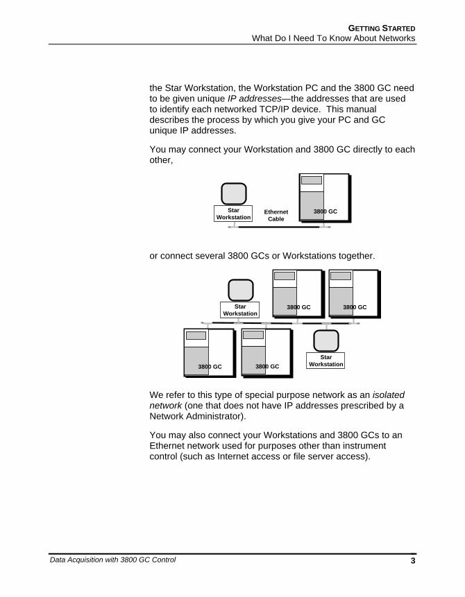
You may connect your Workstation and 3800 GC directly to each other,
3800 GCEthernetCable
StarWorkstation
or connect several 3800 GCs or Workstations together.
3800 GC 3800 GC
3800 GC 3800 GC
StarWorkstation
StarWorkstation
We refer to this type of special purpose network as an isolated network (one that does not have IP addresses prescribed by a Network Administrator).
You may also connect your Workstations and 3800 GCs to an Ethernet network used for purposes other than instrument control (such as Internet access or file server access).
03-914731-00:6 4
3800 GC 3800 GC
3800 GC 3800 GC
Company EthernetNetwork
StarWorkstation
StarWorkstation
StarWorkstation
StarWorkstation
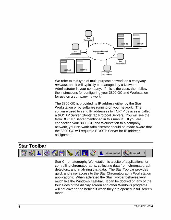
We refer to this type of multi-purpose network as a company network, and it will typically be managed by a Network Administrator in your company. If this is the case, then follow the instructions for configuring your 3800 GC and Workstation for use on a company network.
The 3800 GC is provided its IP address either by the Star Workstation or by software running on your network. The software used to send IP addresses to TCP/IP devices is called a BOOTP Server (Bootstrap Protocol Server). You will see the term BOOTP Server mentioned in this manual. If you are connecting your 3800 GC and Workstation to a company network, your Network Administrator should be made aware that the 3800 GC will require a BOOTP Server for IP address assignment.
Star Toolbar
Star Chromatography Workstation is a suite of applications for controlling chromatographs, collecting data from chromatograph detectors, and analyzing that data. The Star Toolbar provides quick and easy access to the Star Chromatography Workstation applications. When activated the Star Toolbar behaves very much like the Windows Taskbar. It can be docked on any of the four sides of the display screen and other Windows programs will not cover or go behind it when they are opened in full screen mode.
GETTING STARTED Star Toolbar
Data Acquisition with 3800 GC Control 5
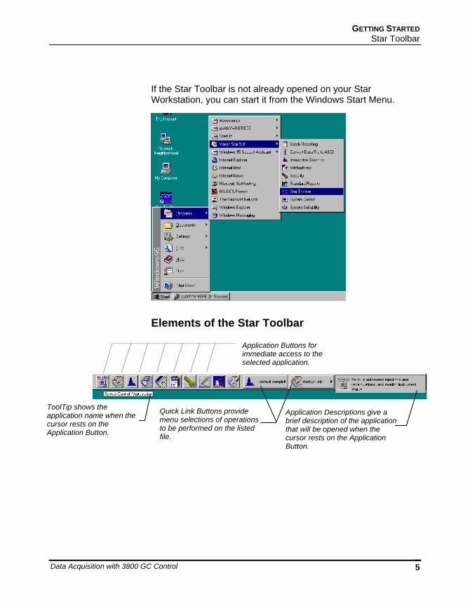
If the Star Toolbar is not already opened on your Star Workstation, you can start it from the Windows Start Menu.
Elements of the Star Toolbar
Application Buttons for immediate access to the selected application.
ToolTip shows the application name when the cursor rests on the Application Button.
Quick Link Buttons provide menu selections of operations to be performed on the listed file.
Application Descriptions give a brief description of the application that will be opened when the cursor rests on the Application Button.
03-914731-00:6 6
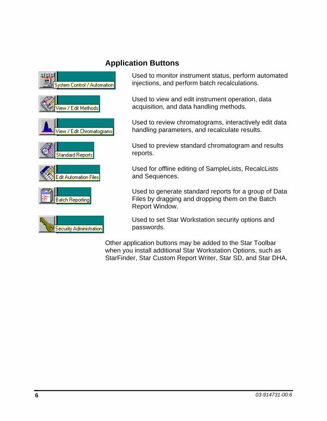
Application Buttons
Used to monitor instrument status, perform automated injections, and perform batch recalculations.
Used to view and edit instrument operation, data acquisition, and data handling methods.
Used to review chromatograms, interactively edit data handling parameters, and recalculate results.
Used to preview standard chromatogram and results reports.
Used for offline editing of SampleLists, RecalcLists and Sequences.
Used to generate standard reports for a group of Data Files by dragging and dropping them on the Batch Report Window.
Used to set Star Workstation security options and passwords.
Other application buttons may be added to the Star Toolbar when you install additional Star Workstation Options, such as StarFinder, Star Custom Report Writer, Star SD, and Star DHA.
GETTING STARTED Star Toolbar
Data Acquisition with 3800 GC Control 7
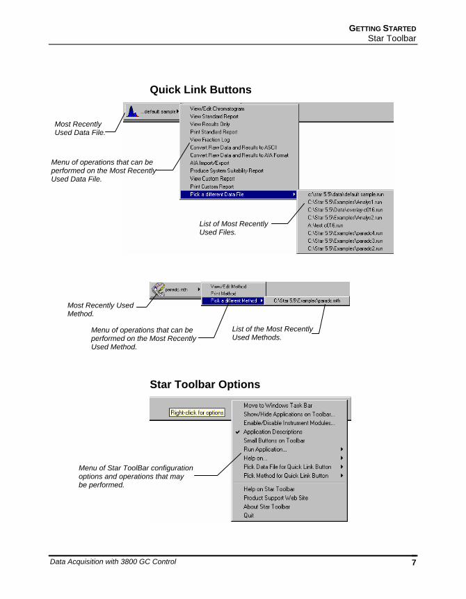
Quick Link Buttons
Star Toolbar Options
Menu of operations that can be performed on the Most Recently Used Data File.
Most Recently Used Data File.
List of Most Recently Used Files.
Most Recently Used Method.
Menu of operations that can be performed on the Most Recently Used Method.
List of the Most Recently Used Methods.
Menu of Star ToolBar configuration options and operations that may be performed.

03-914731-00:6 8
Data Acquisition with 3800 GC Control 9
3800 GC Configuration
Where to Begin Before beginning the configuration process, you should know whether you will be attaching your Workstation and 3800 GC to a company network (as described in the previous section), or an isolated network only used for instrument control. If you have a Network Administrator on site, you may wish to ask which configuration is recommended.
Use this table to determine the order in which you should read the following sections.
1. If an Ethernet card has not been installed and configured on your PC, read Installing and Configuring the Ethernet Card in Your PC on page 10 and one of the following:
No Company Network: Configuring TCP/IP Parameters with No Company Network on page 14.
Company Network: Configuring TCP/IP Parameters for a Company Network on page 16.
2. Read Connecting Your 3800 GC to Your PC or Network on page 18.
3. If you have not already installed the Star Workstation, do so before proceeding.
No Company Network: Read Configuring the 3800 GC Communication (No Company Network) on page 18.
Company Network: Read Configuring the 3800 GC for a Company Network on page 24.
03-914731-00:6 10
4. Continue reading the rest of the sections, starting with Adding 3800 GCs to Instruments in System Control on page 34.
Installing and Configuring the Ethernet Card in Your PC Note: The following section describes a procedure specific to Windows 95. If you are running Windows NT, the windows and dialog boxes shown will differ from those you see on your system, but the procedure described here is essentially the same as the one for Windows NT.
Refer to the installation instructions packaged with your Ethernet card for information on installing the Ethernet card in your computer and configuring the card in Windows 95. Before proceeding, your Ethernet card should be recognized by Windows 95 (the appropriate driver has been loaded and can be configured from the Windows 95 Control Panel). When done, the Network Neighborhood icon should appear on your Windows desktop.
Note: For the following procedure, the use of disks other than the ones that were used for the original Windows installation may result in a Ethernet driver version mismatch that will prevent Windows 95 from starting. Should this occur, it may be necessary to remove the Ethernet Board from the computer to remove the incorrect Ethernet drivers.
3800 GC CONFIGURATION Installing and Configuring the Ethernet Card in Your PC
Data Acquisition with 3800 GC Control 11
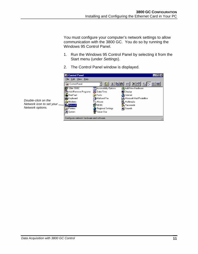
You must configure your computer’s network settings to allow communication with the 3800 GC. You do so by running the Windows 95 Control Panel.
1. Run the Windows 95 Control Panel by selecting it from the Start menu (under Settings).
2. The Control Panel window is displayed.
Double-click on the Network icon to set your Network options.
03-914731-00:6 12
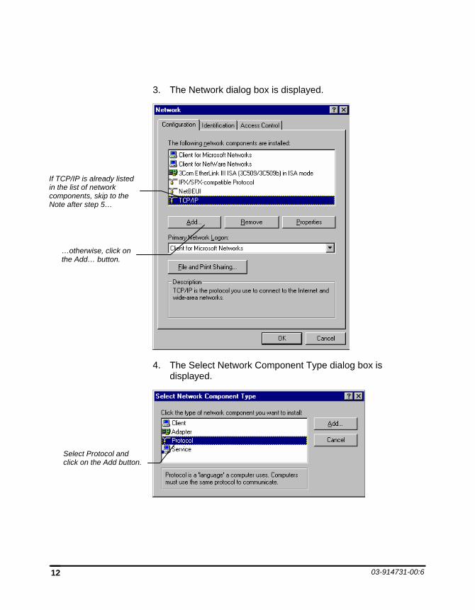
3. The Network dialog box is displayed.
4. The Select Network Component Type dialog box is displayed.
If TCP/IP is already listed in the list of network components, skip to the Note after step 5…
Select Protocol and click on the Add button.
…otherwise, click on the Add… button.
3800 GC CONFIGURATION Installing and Configuring the Ethernet Card in Your PC
Data Acquisition with 3800 GC Control 13
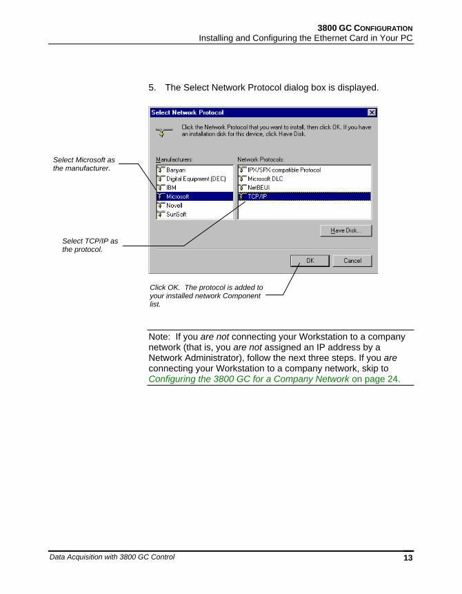
5. The Select Network Protocol dialog box is displayed.
Note: If you are not connecting your Workstation to a company network (that is, you are not assigned an IP address by a Network Administrator), follow the next three steps. If you are connecting your Workstation to a company network, skip to Configuring the 3800 GC for a Company Network on page 24.
Select Microsoft as the manufacturer.
Select TCP/IP as the protocol.
Click OK. The protocol is added to your installed network Component list.
03-914731-00:6 14
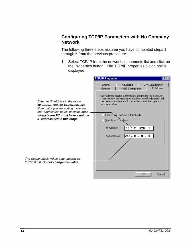
Configuring TCP/IP Parameters with No Company Network The following three steps assume you have completed steps 1 through 5 from the previous procedure.
1. Select TCP/IP from the network components list and click on the Properties button. The TCP/IP properties dialog box is displayed.
Enter an IP address in the range 10.2.128.1 through 10.255.255.254. Note that if you are adding more than one Workstation to this network, each Workstation PC must have a unique IP address within this range.
The Subnet Mask will be automatically set to 255.0.0.0. Do not change this value.
3800 GC CONFIGURATION Installing and Configuring the Ethernet Card in Your PC
Data Acquisition with 3800 GC Control 15
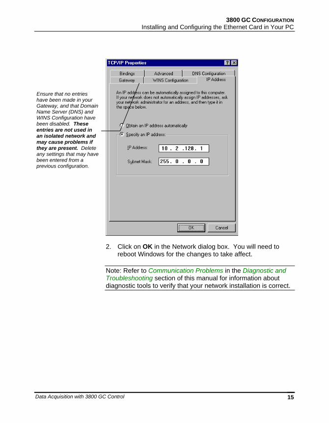
2. Click on OK in the Network dialog box. You will need to reboot Windows for the changes to take affect.
Note: Refer to Communication Problems in the Diagnostic and Troubleshooting section of this manual for information about diagnostic tools to verify that your network installation is correct.
Ensure that no entries have been made in your Gateway, and that Domain Name Server (DNS) and WINS Configuration have been disabled. These entries are not used in an isolated network and may cause problems if they are present. Delete any settings that may have been entered from a previous configuration.
03-914731-00:6 16
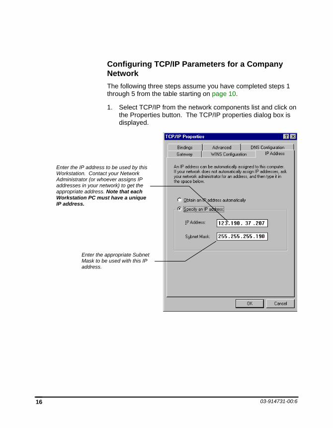
Configuring TCP/IP Parameters for a Company Network The following three steps assume you have completed steps 1 through 5 from the table starting on page 10.
1. Select TCP/IP from the network components list and click on the Properties button. The TCP/IP properties dialog box is displayed.
Enter the IP address to be used by this Workstation. Contact your Network Administrator (or whoever assigns IP addresses in your network) to get the appropriate address. Note that each Workstation PC must have a unique IP address.
Enter the appropriate Subnet Mask to be used with this IP address.
3800 GC CONFIGURATION Installing and Configuring the Ethernet Card in Your PC
Data Acquisition with 3800 GC Control 17
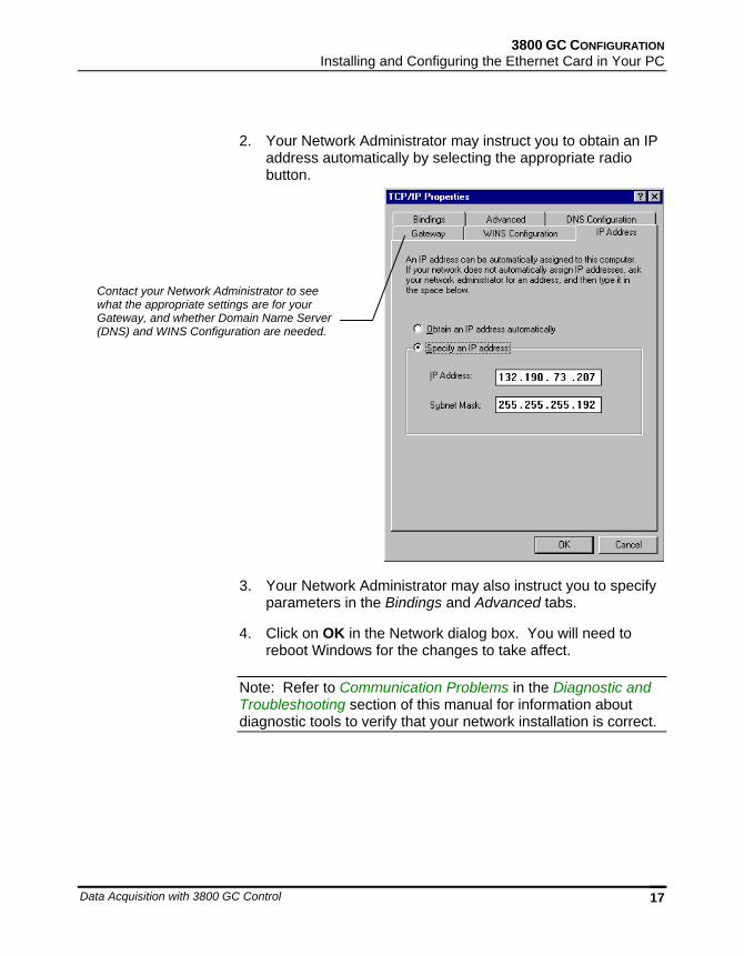
2. Your Network Administrator may instruct you to obtain an IP address automatically by selecting the appropriate radio button.
3. Your Network Administrator may also instruct you to specify parameters in the Bindings and Advanced tabs.
4. Click on OK in the Network dialog box. You will need to reboot Windows for the changes to take affect.
Note: Refer to Communication Problems in the Diagnostic and Troubleshooting section of this manual for information about diagnostic tools to verify that your network installation is correct.
Contact your Network Administrator to see what the appropriate settings are for your Gateway, and whether Domain Name Server (DNS) and WINS Configuration are needed.
03-914731-00:6 18
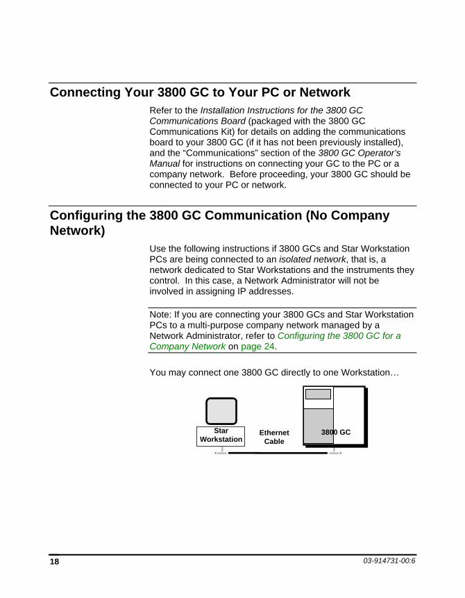
Connecting Your 3800 GC to Your PC or Network Refer to the Installation Instructions for the 3800 GC Communications Board (packaged with the 3800 GC Communications Kit) for details on adding the communications board to your 3800 GC (if it has not been previously installed), and the “Communications” section of the 3800 GC Operator’s Manual for instructions on connecting your GC to the PC or a company network. Before proceeding, your 3800 GC should be connected to your PC or network.
Configuring the 3800 GC Communication (No Company Network)
Use the following instructions if 3800 GCs and Star Workstation PCs are being connected to an isolated network, that is, a network dedicated to Star Workstations and the instruments they control. In this case, a Network Administrator will not be involved in assigning IP addresses.
Note: If you are connecting your 3800 GCs and Star Workstation PCs to a multi-purpose company network managed by a Network Administrator, refer to Configuring the 3800 GC for a Company Network on page 24.
You may connect one 3800 GC directly to one Workstation…
3800 GC Ethernet Cable
Star Workstation
3800 GC CONFIGURATION Configuring the 3800 GC Communication (No Company Network)
Data Acquisition with 3800 GC Control 19
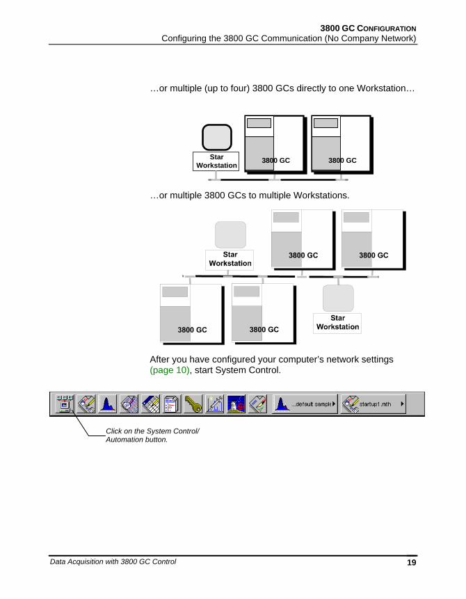
…or multiple (up to four) 3800 GCs directly to one Workstation…
3800 GC 3800 GCStarWorkstation
…or multiple 3800 GCs to multiple Workstations.
After you have configured your computer’s network settings (page 10), start System Control.
Click on the System Control/ Automation button.
03-914731-00:6 20
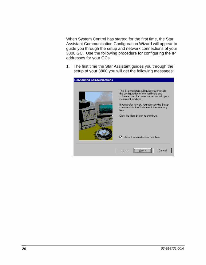
When System Control has started for the first time, the Star Assistant Communication Configuration Wizard will appear to guide you through the setup and network connections of your 3800 GC. Use the following procedure for configuring the IP addresses for your GCs.
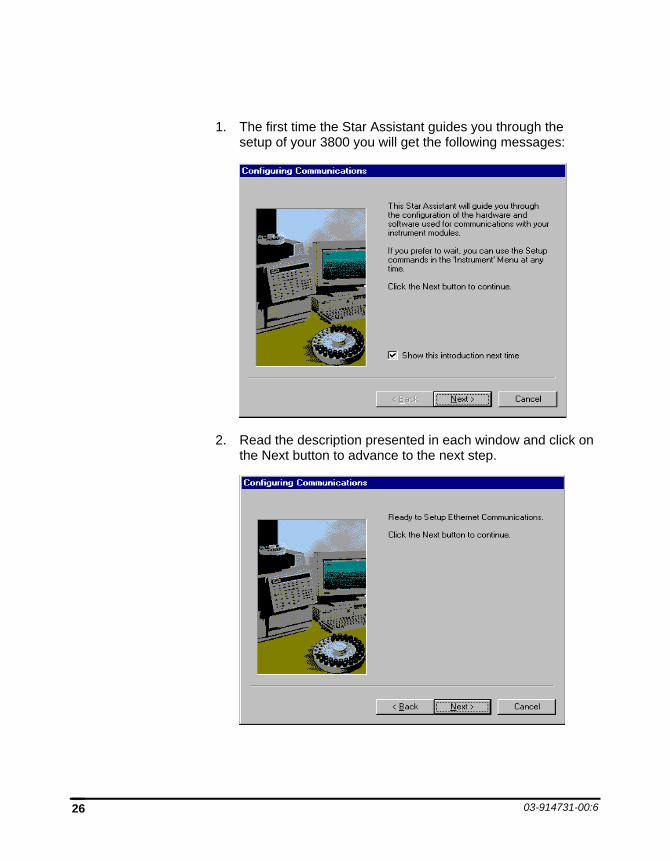
1. The first time the Star Assistant guides you through the setup of your 3800 you will get the following messages:
3800 GC CONFIGURATION Configuring the 3800 GC Communication (No Company Network)
Data Acquisition with 3800 GC Control 21
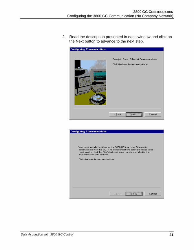
2. Read the description presented in each window and click on the Next button to advance to the next step.
03-914731-00:6 22
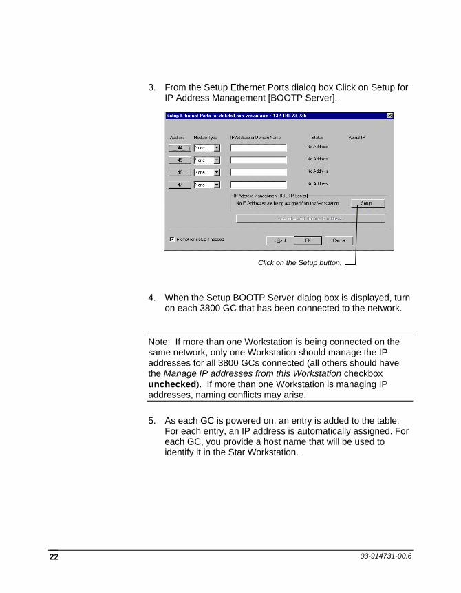
3. From the Setup Ethernet Ports dialog box Click on Setup for IP Address Management [BOOTP Server].
4. When the Setup BOOTP Server dialog box is displayed, turn on each 3800 GC that has been connected to the network.
Note: If more than one Workstation is being connected on the same network, only one Workstation should manage the IP addresses for all 3800 GCs connected (all others should have the Manage IP addresses from this Workstation checkbox unchecked). If more than one Workstation is managing IP addresses, naming conflicts may arise.
5. As each GC is powered on, an entry is added to the table. For each entry, an IP address is automatically assigned. For each GC, you provide a host name that will be used to identify it in the Star Workstation.
Click on the Setup button.
3800 GC CONFIGURATION Configuring the 3800 GC Communication (No Company Network)
Data Acquisition with 3800 GC Control 23
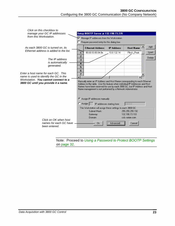
Note: Proceed to Using a Password to Protect BOOTP Settings on page 32.
As each 3800 GC is turned on, its Ethernet address is added to the list.
The IP address is automatically generated.
Click on this checkbox to manage your GC IP addresses from this Workstation.
Enter a host name for each GC. This name is used to identify the GC in the Workstation. You cannot connect to a 3800 GC until you provide it a name.
Click on OK when host names for each GC have been entered.
03-914731-00:6 24
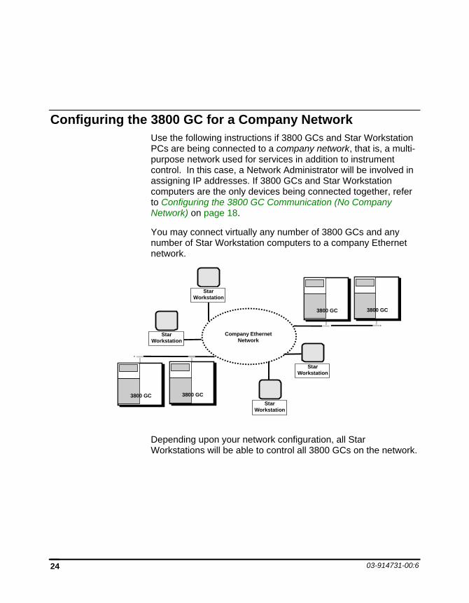
Configuring the 3800 GC for a Company Network Use the following instructions if 3800 GCs and Star Workstation PCs are being connected to a company network, that is, a multi-purpose network used for services in addition to instrument control. In this case, a Network Administrator will be involved in assigning IP addresses. If 3800 GCs and Star Workstation computers are the only devices being connected together, refer to Configuring the 3800 GC Communication (No Company Network) on page 18.
You may connect virtually any number of 3800 GCs and any number of Star Workstation computers to a company Ethernet network.
3800 GC 3800 GC
3800 GC 3800 GC
Company EthernetNetwork
StarWorkstation
StarWorkstation
StarWorkstation
StarWorkstation
Depending upon your network configuration, all Star Workstations will be able to control all 3800 GCs on the network.
3800 GC CONFIGURATION Configuring the 3800 GC for a Company Network
Data Acquisition with 3800 GC Control 25
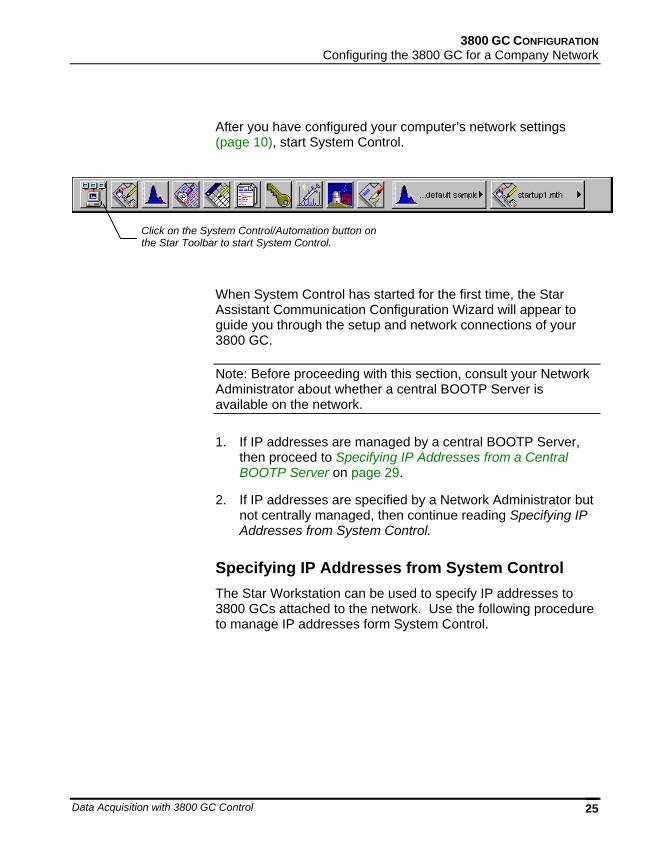
After you have configured your computer’s network settings (page 10), start System Control.
When System Control has started for the first time, the Star Assistant Communication Configuration Wizard will appear to guide you through the setup and network connections of your 3800 GC.
Note: Before proceeding with this section, consult your Network Administrator about whether a central BOOTP Server is available on the network.
1. If IP addresses are managed by a central BOOTP Server, then proceed to Specifying IP Addresses from a Central BOOTP Server on page 29.
2. If IP addresses are specified by a Network Administrator but not centrally managed, then continue reading Specifying IP Addresses from System Control.
Specifying IP Addresses from System Control The Star Workstation can be used to specify IP addresses to 3800 GCs attached to the network. Use the following procedure to manage IP addresses form System Control.
Click on the System Control/Automation button on the Star Toolbar to start System Control.
03-914731-00:6 26
1. The first time the Star Assistant guides you through the setup of your 3800 you will get the following messages:
2. Read the description presented in each window and click on the Next button to advance to the next step.
3800 GC CONFIGURATION Configuring the 3800 GC for a Company Network
Data Acquisition with 3800 GC Control 27
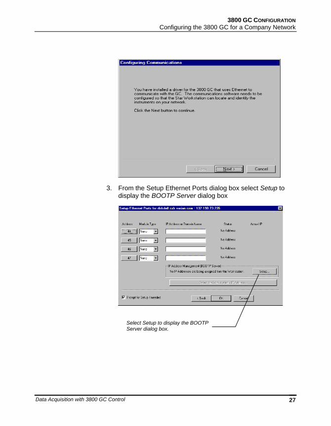
3. From the Setup Ethernet Ports dialog box select Setup to display the BOOTP Server dialog box
Select Setup to display the BOOTP Server dialog box.
03-914731-00:6 28
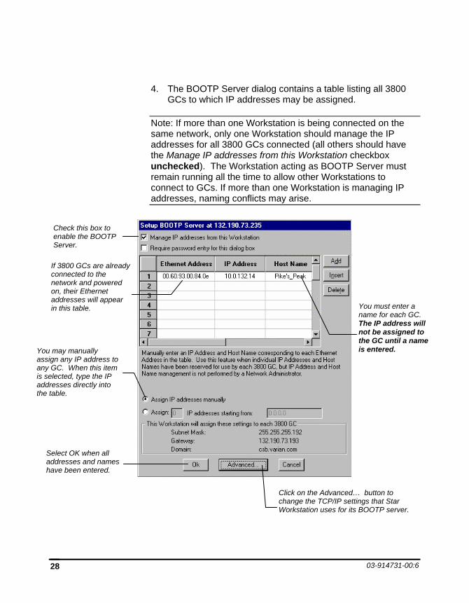
4. The BOOTP Server dialog contains a table listing all 3800 GCs to which IP addresses may be assigned.
Note: If more than one Workstation is being connected on the same network, only one Workstation should manage the IP addresses for all 3800 GCs connected (all others should have the Manage IP addresses from this Workstation checkbox unchecked). The Workstation acting as BOOTP Server must remain running all the time to allow other Workstations to connect to GCs. If more than one Workstation is managing IP addresses, naming conflicts may arise.
Check this box to enable the BOOTP Server.
If 3800 GCs are already connected to the network and powered on, their Ethernet addresses will appear in this table.
You may manually assign any IP address to any GC. When this item is selected, type the IP addresses directly into the table.
You must enter a name for each GC. The IP address will not be assigned to the GC until a name is entered.
Select OK when all addresses and names have been entered.
Click on the Advanced… button to change the TCP/IP settings that Star Workstation uses for its BOOTP server.
3800 GC CONFIGURATION Configuring the 3800 GC for a Company Network
Data Acquisition with 3800 GC Control 29
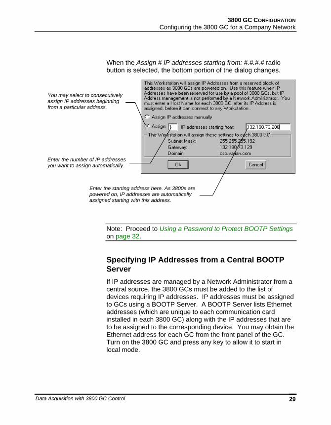
When the Assign # IP addresses starting from: #.#.#.# radio button is selected, the bottom portion of the dialog changes.
Note: Proceed to Using a Password to Protect BOOTP Settings on page 32.
Specifying IP Addresses from a Central BOOTP Server If IP addresses are managed by a Network Administrator from a central source, the 3800 GCs must be added to the list of devices requiring IP addresses. IP addresses must be assigned to GCs using a BOOTP Server. A BOOTP Server lists Ethernet addresses (which are unique to each communication card installed in each 3800 GC) along with the IP addresses that are to be assigned to the corresponding device. You may obtain the Ethernet address for each GC from the front panel of the GC. Turn on the 3800 GC and press any key to allow it to start in local mode.
You may select to consecutively assign IP addresses beginning from a particular address.
Enter the starting address here. As 3800s are powered on, IP addresses are automatically assigned starting with this address.
Enter the number of IP addresses you want to assign automatically.
03-914731-00:6 30
ENTRY
TABLE EDIT
PAGE CURSOR
NEWLINE
HELP UNDO
DELETELINE
CLEARTABLE
ENTERDECRINCR
SAMPLEDELIVERY INJECTOR
GC CONTROL INSTRUMENTFLOW/
PRESSURE
COLUMNOVEN DETECTOR OUTPUT
METHOD SEQUENCESELECT/
EDIT
PRIORITY SAMPLE
SUSPEND RESUME
METHOD
AUTOMATION
ACTIVATE
SINGLE METHOD
EDIT MENU
NOTREADY READY RUN
START STOP
STATUS SETUP
MENU
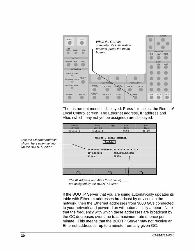
The Instrument menu is displayed. Press 1 to select the Remote/ Local Control screen. The Ethernet address, IP address and Alias (which may not yet be assigned) are displayed.
ACTIVEMETHOD
EDITMETHOD
CTRL RUNTIME
ENDTIME
Method 1 Method 1 0.00 20.00
REMOTE / LOCAL CONTROL
Enable
Ethernet Address: XX:XX:XX:XX:XX:XXIP Address: XXX.XXX.XX.XXXAlias: 3800A
If the BOOTP Server that you are using automatically updates its table with Ethernet addresses broadcast by devices on the network, then the Ethernet addresses from 3800 GCs connected to your network and powered on will automatically appear. Note that the frequency with which these addresses are broadcast by the GC decreases over time to a maximum rate of once per minute. This means that the BOOTP Server may not receive an Ethernet address for up to a minute from any given GC.
When the GC has completed its initialization process, press the menu button.
Use the Ethernet address shown here when setting up the BOOTP Server.
The IP Address and Alias (host name) are assigned by the BOOTP Server.
3800 GC CONFIGURATION Configuring the 3800 GC for a Company Network
Data Acquisition with 3800 GC Control 31
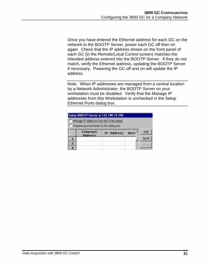
Once you have entered the Ethernet address for each GC on the network to the BOOTP Server, power each GC off then on again. Check that the IP address shown on the front panel of each GC (in the Remote/Local Control screen) matches the intended address entered into the BOOTP Server. If they do not match, verify the Ethernet address, updating the BOOTP Server if necessary. Powering the GC off and on will update the IP address.
Note: When IP addresses are managed from a central location by a Network Administrator, the BOOTP Server on your workstation must be disabled. Verify that the Manage IP addresses from this Workstation is unchecked in the Setup Ethernet Ports dialog box.
03-914731-00:6 32
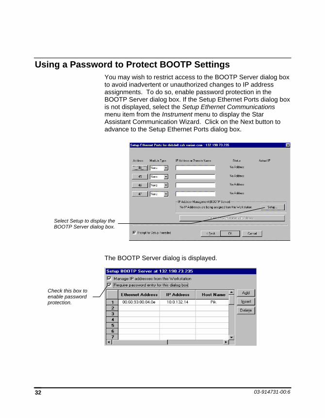
Using a Password to Protect BOOTP Settings You may wish to restrict access to the BOOTP Server dialog box to avoid inadvertent or unauthorized changes to IP address assignments. To do so, enable password protection in the BOOTP Server dialog box. If the Setup Ethernet Ports dialog box is not displayed, select the Setup Ethernet Communications menu item from the Instrument menu to display the Star Assistant Communication Wizard. Click on the Next button to advance to the Setup Ethernet Ports dialog box.
The BOOTP Server dialog is displayed.
Select Setup to display the BOOTP Server dialog box.
Check this box to enable password protection.
3800 GC CONFIGURATION Using a Password to Protect BOOTP Settings
Data Acquisition with 3800 GC Control 33
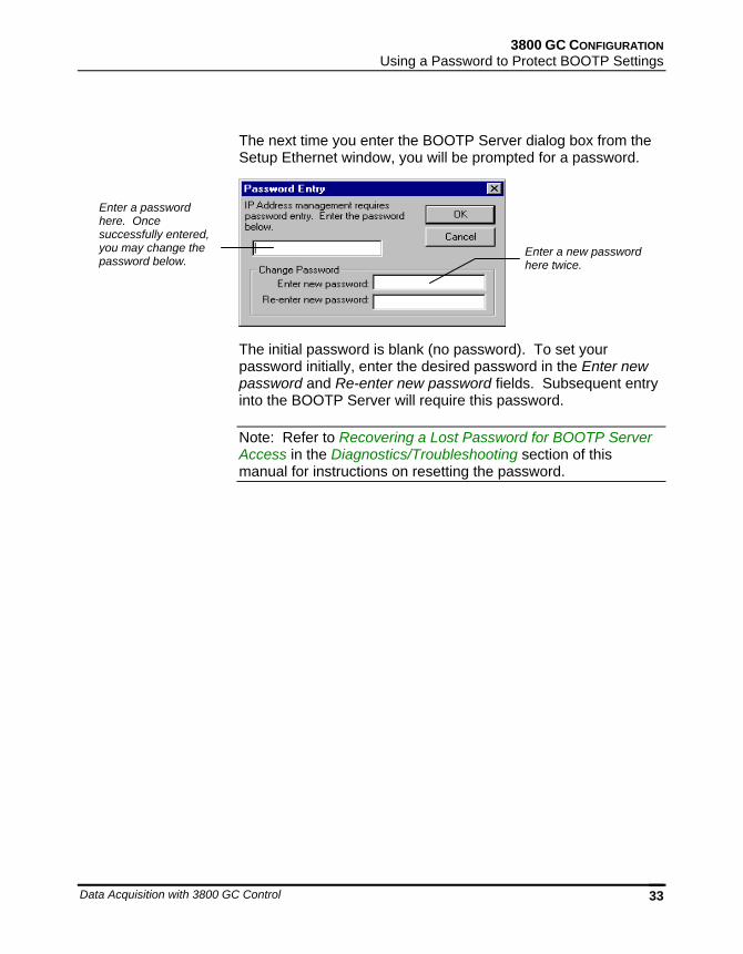
The next time you enter the BOOTP Server dialog box from the Setup Ethernet window, you will be prompted for a password.
The initial password is blank (no password). To set your password initially, enter the desired password in the Enter new password and Re-enter new password fields. Subsequent entry into the BOOTP Server will require this password.
Note: Refer to Recovering a Lost Password for BOOTP Server Access in the Diagnostics/Troubleshooting section of this manual for instructions on resetting the password.
Enter a new password here twice.
Enter a password here. Once successfully entered, you may change the password below.
03-914731-00:6 34
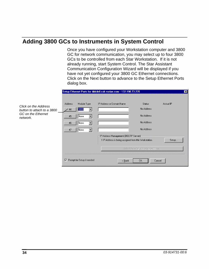
Adding 3800 GCs to Instruments in System Control Once you have configured your Workstation computer and 3800 GC for network communication, you may select up to four 3800 GCs to be controlled from each Star Workstation. If it is not already running, start System Control. The Star Assistant Communication Configuration Wizard will be displayed if you have not yet configured your 3800 GC Ethernet connections. Click on the Next button to advance to the Setup Ethernet Ports dialog box.
Click on the Address button to attach to a 3800 GC on the Ethernet network.
3800 GC CONFIGURATION Adding 3800 GCs to Instruments in System Control
Data Acquisition with 3800 GC Control 35
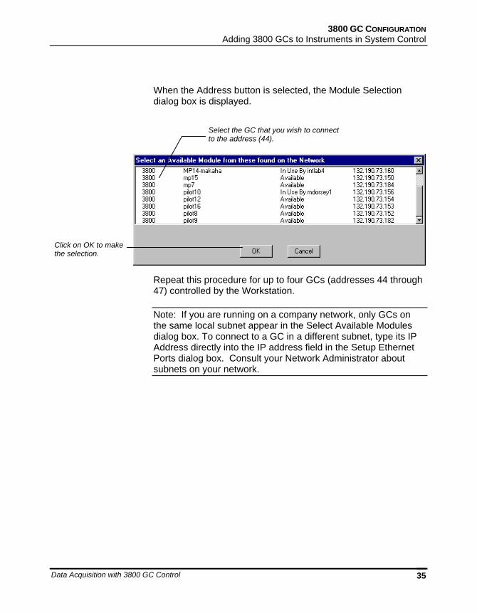
When the Address button is selected, the Module Selection dialog box is displayed.
Repeat this procedure for up to four GCs (addresses 44 through 47) controlled by the Workstation.
Note: If you are running on a company network, only GCs on the same local subnet appear in the Select Available Modules dialog box. To connect to a GC in a different subnet, type its IP Address directly into the IP address field in the Setup Ethernet Ports dialog box. Consult your Network Administrator about subnets on your network.
Select the GC that you wish to connect to the address (44).
Click on OK to make the selection.
03-914731-00:6 36
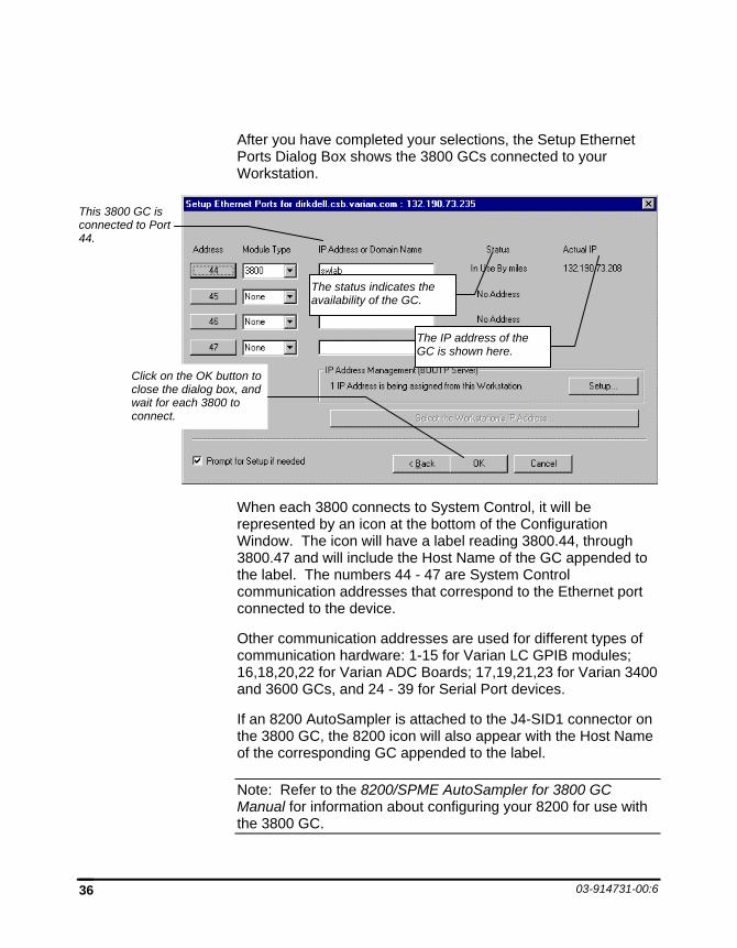
After you have completed your selections, the Setup Ethernet Ports Dialog Box shows the 3800 GCs connected to your Workstation.
When each 3800 connects to System Control, it will be represented by an icon at the bottom of the Configuration Window. The icon will have a label reading 3800.44, through 3800.47 and will include the Host Name of the GC appended to the label. The numbers 44 - 47 are System Control communication addresses that correspond to the Ethernet port connected to the device.
Other communication addresses are used for different types of communication hardware: 1-15 for Varian LC GPIB modules; 16,18,20,22 for Varian ADC Boards; 17,19,21,23 for Varian 3400 and 3600 GCs, and 24 - 39 for Serial Port devices.
If an 8200 AutoSampler is attached to the J4-SID1 connector on the 3800 GC, the 8200 icon will also appear with the Host Name of the corresponding GC appended to the label.
Note: Refer to the 8200/SPME AutoSampler for 3800 GC Manual for information about configuring your 8200 for use with the 3800 GC.
Click on the OK button to close the dialog box, and wait for each 3800 to connect.
This 3800 GC is connected to Port 44.
The status indicates the availability of the GC.
The IP address of the GC is shown here.
3800 GC CONFIGURATION Adding 3800 GCs to Instruments in System Control
Data Acquisition with 3800 GC Control 37
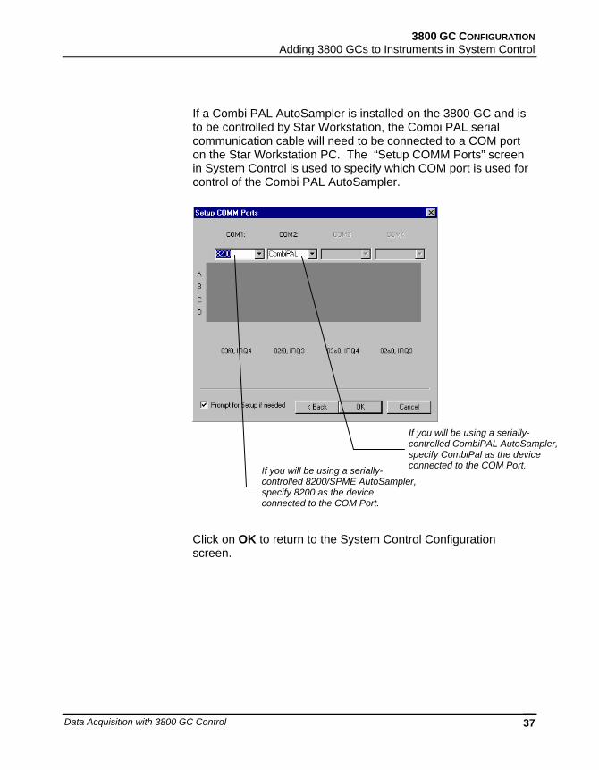
If a Combi PAL AutoSampler is installed on the 3800 GC and is to be controlled by Star Workstation, the Combi PAL serial communication cable will need to be connected to a COM port on the Star Workstation PC. The “Setup COMM Ports” screen in System Control is used to specify which COM port is used for control of the Combi PAL AutoSampler.
Click on OK to return to the System Control Configuration screen.
If you will be using a serially-controlled 8200/SPME AutoSampler, specify 8200 as the device connected to the COM Port.
If you will be using a serially-controlled CombiPAL AutoSampler, specify CombiPal as the device connected to the COM Port.
03-914731-00:6 38
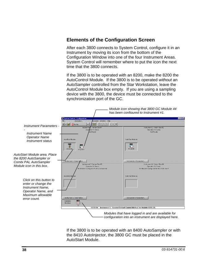
Elements of the Configuration Screen After each 3800 connects to System Control, configure it in an Instrument by moving its icon from the bottom of the Configuration Window into one of the four Instrument Areas. System Control will remember where to put the icon the next time that the 3800 connects.
If the 3800 is to be operated with an 8200, make the 8200 the AutoControl Module. If the 3800 is to be operated without an AutoSampler controlled from the Star Workstation, leave the AutoControl Module box empty. If you are using a sampling device with the 3800, the device must be connected to the synchronization port of the GC.
If the 3800 is to be operated with an 8400 AutoSampler or with the 8410 AutoInjector, the 3800 GC must be placed in the AutoStart Module.
Modules that have logged in and are available for configuration into an instrument are displayed here.
Instrument Parameters -- Instrument Name Operator Name Instrument status
Module icon showing that 3800 GC Module 44 has been configured to Instrument #1.
AutoStart Module area. Place the 8200 AutoSampler or Combi PAL AutoSampler Module icon in this box.
Click on this button to enter or change the Instrument Name, Operator Name, and Maximum allowable error count.
3800 GC CONFIGURATION The Instrument Window
Data Acquisition with 3800 GC Control 39
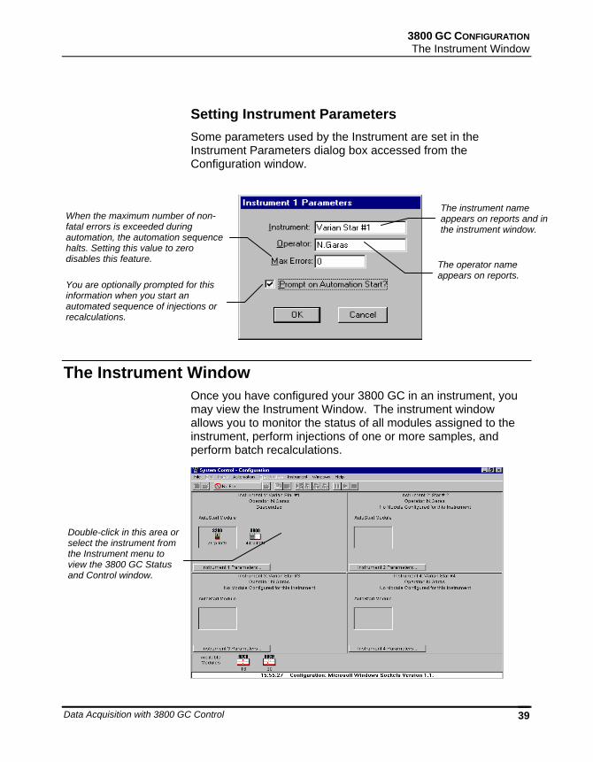
Setting Instrument Parameters Some parameters used by the Instrument are set in the Instrument Parameters dialog box accessed from the Configuration window.
The Instrument Window Once you have configured your 3800 GC in an instrument, you may view the Instrument Window. The instrument window allows you to monitor the status of all modules assigned to the instrument, perform injections of one or more samples, and perform batch recalculations.
Double-click in this area or select the instrument from the Instrument menu to view the 3800 GC Status and Control window.
The instrument name appears on reports and in the instrument window.
The operator name appears on reports.
When the maximum number of non-fatal errors is exceeded during automation, the automation sequence halts. Setting this value to zero disables this feature.
You are optionally prompted for this information when you start an automated sequence of injections or recalculations.
03-914731-00:6 40
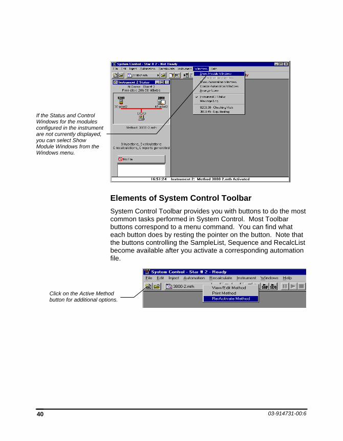
Elements of System Control Toolbar System Control Toolbar provides you with buttons to do the most common tasks performed in System Control. Most Toolbar buttons correspond to a menu command. You can find what each button does by resting the pointer on the button. Note that the buttons controlling the SampleList, Sequence and RecalcList become available after you activate a corresponding automation file.
If the Status and Control Windows for the modules configured in the instrument are not currently displayed, you can select Show Module Windows from the Windows menu.
Click on the Active Method button for additional options.
3800 GC CONFIGURATION The 3800 GC Status and Control Window
Data Acquisition with 3800 GC Control 41
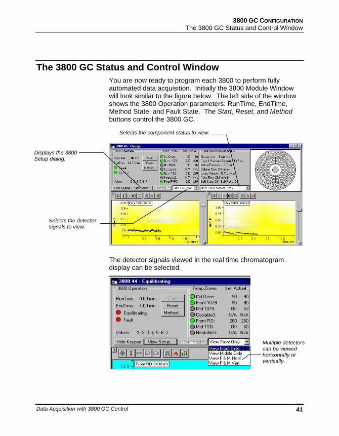
The 3800 GC Status and Control Window You are now ready to program each 3800 to perform fully automated data acquisition. Initially the 3800 Module Window will look similar to the figure below. The left side of the window shows the 3800 Operation parameters: RunTime, EndTime, Method State, and Fault State. The Start, Reset, and Method buttons control the 3800 GC.
The detector signals viewed in the real time chromatogram display can be selected.
Displays the 3800 Setup dialog.
Selects the detector signals to view.
Multiple detectors can be viewed horizontally or vertically.
Selects the component status to view.
03-914731-00:6 42
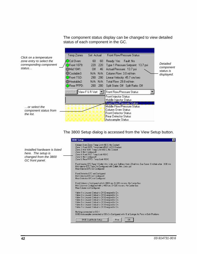
The component status display can be changed to view detailed status of each component in the GC.
The 3800 Setup dialog is accessed from the View Setup button.
Installed hardware is listed here. The setup is changed from the 3800 GC front panel.
Click on a temperature zone entry to select the corresponding component status…
…or select the component status from the list.
Detailed component status is displayed.
3800 GC CONFIGURATION The Real-Time Chromatogram Display
Data Acquisition with 3800 GC Control 43
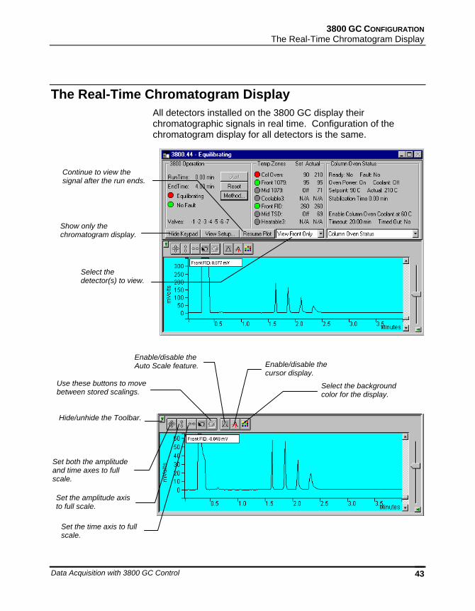
The Real-Time Chromatogram Display All detectors installed on the 3800 GC display their chromatographic signals in real time. Configuration of the chromatogram display for all detectors is the same.
Show only the chromatogram display.
Select the detector(s) to view.
Continue to view the signal after the run ends.
Hide/unhide the Toolbar.
Set both the amplitude and time axes to full scale.
Set the amplitude axis to full scale.
Set the time axis to full scale.
Use these buttons to move between stored scalings.
Enable/disable the Auto Scale feature. Enable/disable the
cursor display.
Select the background color for the display.
03-914731-00:6 44
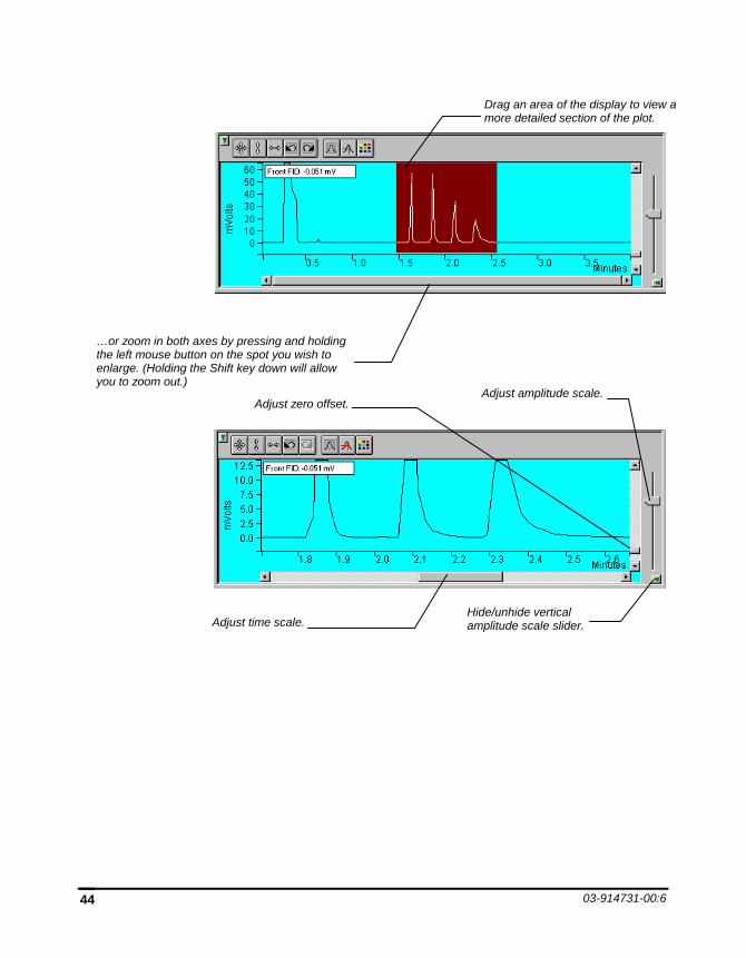
Hide/unhide vertical amplitude scale slider.
Adjust zero offset.
Adjust time scale.
Adjust amplitude scale.
…or zoom in both axes by pressing and holding the left mouse button on the spot you wish to enlarge. (Holding the Shift key down will allow you to zoom out.)
Drag an area of the display to view a more detailed section of the plot.
3800 GC CONFIGURATION The Combi PAL AutoSampler Status and Control Window
Data Acquisition with 3800 GC Control 45
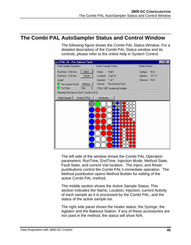
The Combi PAL AutoSampler Status and Control Window The following figure shows the Combi PAL Status Window. For a detailed description of the Combi PAL Status window and its controls, please refer to the online help in System Control.
The left side of the window shows the Combi PAL Operation parameters: RunTime, EndTime, Injection Mode, Method State, Fault State, and current Vial location. The Inject, and Reset pushbuttons control the Combi PAL’s immediate operation. The Method pushbutton opens Method Builder for editing of the active Combi PAL method.
The middle section shows the Active Sample Status. This section indicates the Name, Location, Injection, current Activity of each sample as it is processed by the Combi PAL, and the status of the active sample list.
The right side panel shows the heater status: the Syringe, the Agitator and the Bakeout Station. If any of these accessories are not used in the method, the status will show N/A.
03-914731-00:6 46
A row of buttons separates the Combi PAL Status windows from the sample tray layout window. The Hide Keypad button allows you to conceal the keypad display and gain a larger view of the sample tray. The Unlock CPAL button releases Star Workstation control of the Combi PAL to establish manual control. It then becomes a “Lock” button that allows you to regain control.
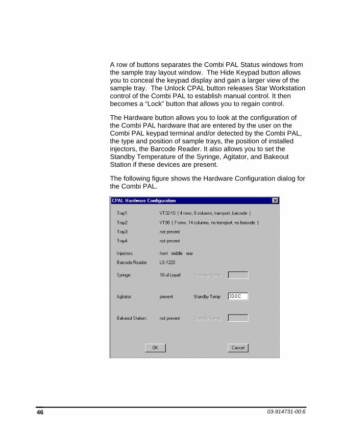
The Hardware button allows you to look at the configuration of the Combi PAL hardware that are entered by the user on the Combi PAL keypad terminal and/or detected by the Combi PAL, the type and position of sample trays, the position of installed injectors, the Barcode Reader. It also allows you to set the Standby Temperature of the Syringe, Agitator, and Bakeout Station if these devices are present.
The following figure shows the Hardware Configuration dialog for the Combi PAL.
3800 GC CONFIGURATION The Combi PAL AutoSampler Status and Control Window
Data Acquisition with 3800 GC Control 47
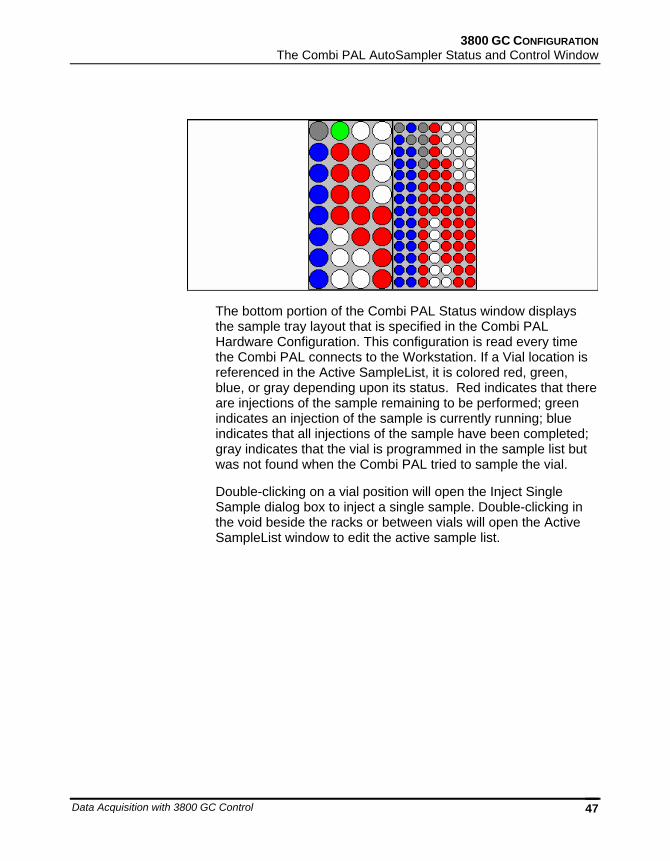
The bottom portion of the Combi PAL Status window displays the sample tray layout that is specified in the Combi PAL Hardware Configuration. This configuration is read every time the Combi PAL connects to the Workstation. If a Vial location is referenced in the Active SampleList, it is colored red, green, blue, or gray depending upon its status. Red indicates that there are injections of the sample remaining to be performed; green indicates an injection of the sample is currently running; blue indicates that all injections of the sample have been completed; gray indicates that the vial is programmed in the sample list but was not found when the Combi PAL tried to sample the vial.
Double-clicking on a vial position will open the Inject Single Sample dialog box to inject a single sample. Double-clicking in the void beside the racks or between vials will open the Active SampleList window to edit the active sample list.
03-914731-00:6 48
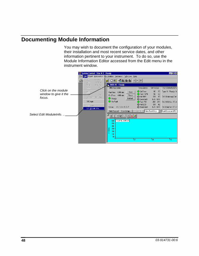
Documenting Module Information You may wish to document the configuration of your modules, their installation and most recent service dates, and other information pertinent to your instrument. To do so, use the Module Information Editor accessed from the Edit menu in the instrument window.
Click on the module window to give it the focus.
Select Edit ModuleInfo. ..
3800 GC CONFIGURATION Documenting Module Information
Data Acquisition with 3800 GC Control 49
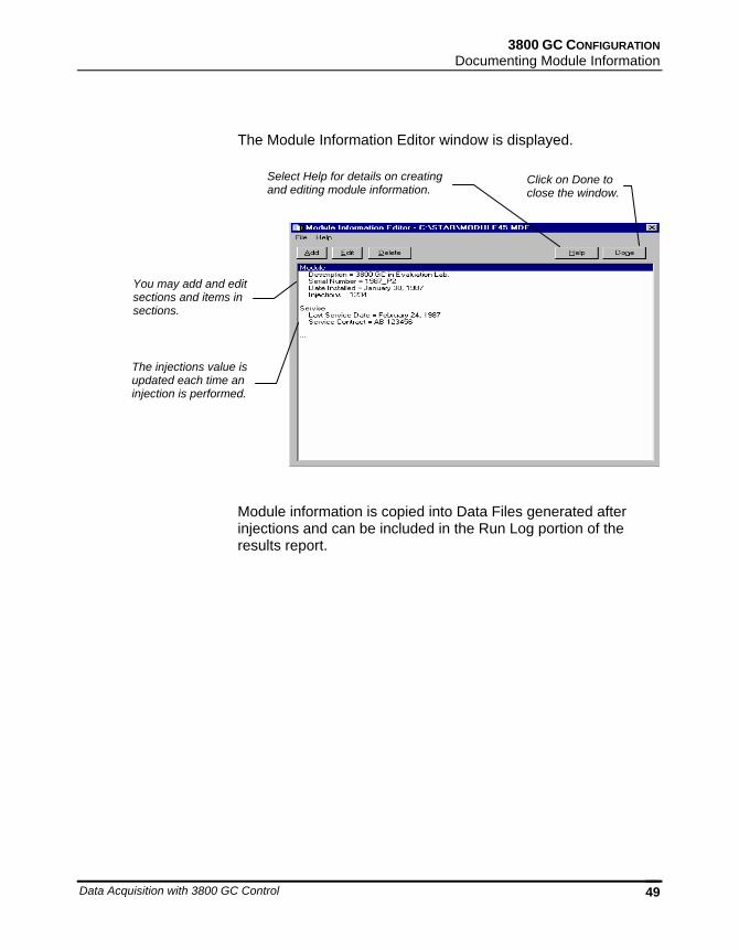
The Module Information Editor window is displayed.
Module information is copied into Data Files generated after injections and can be included in the Run Log portion of the results report.
Select Help for details on creating and editing module information.
Click on Done to close the window.
You may add and edit sections and items in sections.
The injections value is updated each time an injection is performed.

03-914731-00:6 50
Data Acquisition with 3800 GC Control 51
Building 3800 GC Methods
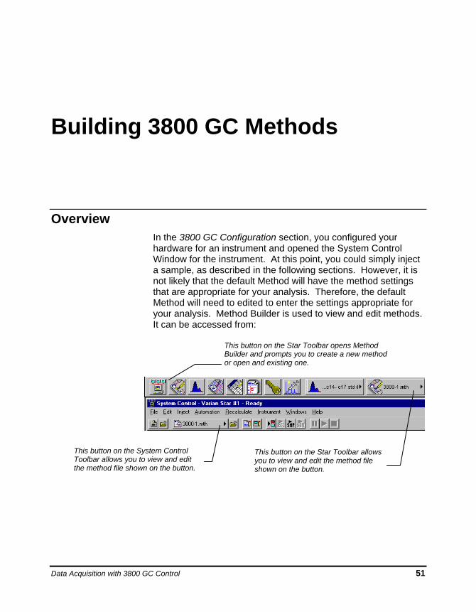
Overview In the 3800 GC Configuration section, you configured your hardware for an instrument and opened the System Control Window for the instrument. At this point, you could simply inject a sample, as described in the following sections. However, it is not likely that the default Method will have the method settings that are appropriate for your analysis. Therefore, the default Method will need to edited to enter the settings appropriate for your analysis. Method Builder is used to view and edit methods. It can be accessed from:
This button on the Star Toolbar opens Method Builder and prompts you to create a new method or open and existing one.
This button on the Star Toolbar allows you to view and edit the method file shown on the button.
This button on the System Control Toolbar allows you to view and edit the method file shown on the button.
52 03-914731-00:6
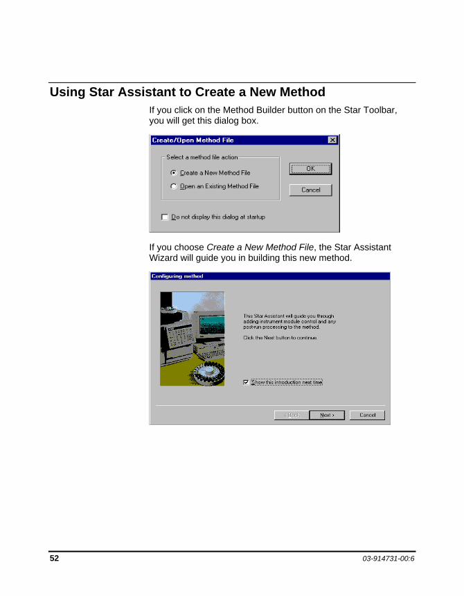
Using Star Assistant to Create a New Method If you click on the Method Builder button on the Star Toolbar, you will get this dialog box.
If you choose Create a New Method File, the Star Assistant Wizard will guide you in building this new method.
BUILDING 3800 GC METHODS Using Star Assistant to Create a New Method
Data Acquisition with 3800 GC Control 53
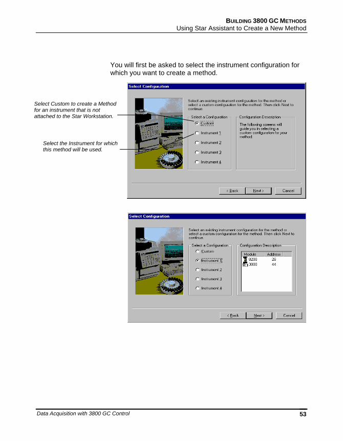
You will first be asked to select the instrument configuration for which you want to create a method.
Select Custom to create a Method for an instrument that is not attached to the Star Workstation.
Select the Instrument for which this method will be used.
54 03-914731-00:6
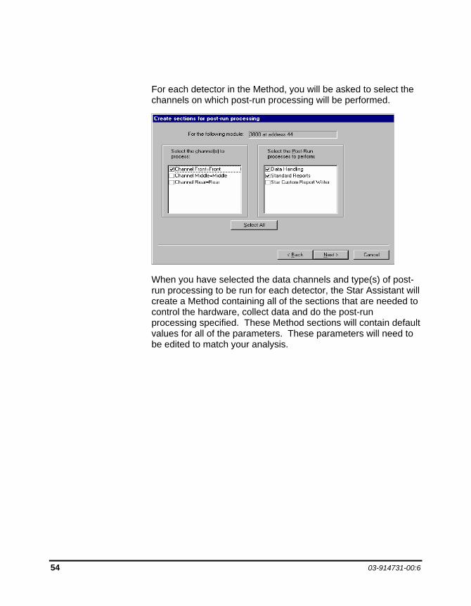
For each detector in the Method, you will be asked to select the channels on which post-run processing will be performed.
When you have selected the data channels and type(s) of post-run processing to be run for each detector, the Star Assistant will create a Method containing all of the sections that are needed to control the hardware, collect data and do the post-run processing specified. These Method sections will contain default values for all of the parameters. These parameters will need to be edited to match your analysis.
BUILDING 3800 GC METHODS The Method Builder Window
Data Acquisition with 3800 GC Control 55
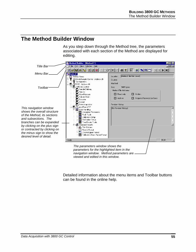
The Method Builder Window As you step down through the Method tree, the parameters associated with each section of the Method are displayed for editing.
Detailed information about the menu items and Toolbar buttons can be found in the online help.
Title Bar
Menu Bar
This navigation window shows the overall structure of the Method, its sections and subsections. The branches can be expanded by clicking on the plus sign or contracted by clicking on the minus sign to show the desired level of detail.
The parameters window shows the parameters for the highlighted item in the navigation window. Method parameters are viewed and edited in this window.
Toolbar
56 03-914731-00:6
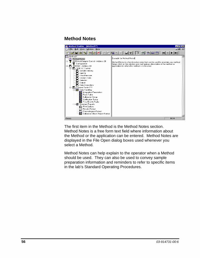
Method Notes
The first item in the Method is the Method Notes section. Method Notes is a free form text field where information about the Method or the application can be entered. Method Notes are displayed in the File Open dialog boxes used whenever you select a Method.
Method Notes can help explain to the operator when a Method should be used. They can also be used to convey sample preparation information and reminders to refer to specific items in the lab’s Standard Operating Procedures.
BUILDING 3800 GC METHODS The 3800 GC Method Windows
Data Acquisition with 3800 GC Control 57
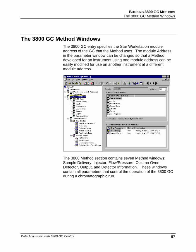
The 3800 GC Method Windows The 3800 GC entry specifies the Star Workstation module address of the GC that the Method uses. The module Address in the parameter window can be changed so that a Method developed for an instrument using one module address can be easily modified for use on another instrument at a different module address.
The 3800 Method section contains seven Method windows: Sample Delivery, Injector, Flow/Pressure, Column Oven, Detector, Output, and Detector Information. These windows contain all parameters that control the operation of the 3800 GC during a chromatographic run.
58 03-914731-00:6
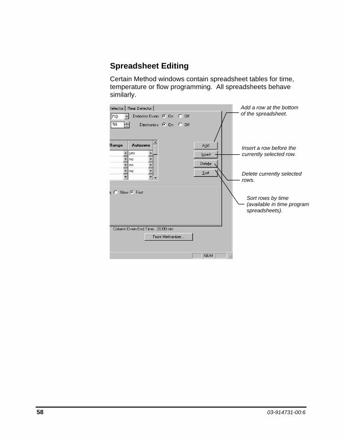
Spreadsheet Editing Certain Method windows contain spreadsheet tables for time, temperature or flow programming. All spreadsheets behave similarly.
Insert a row before the currently selected row.
Delete currently selected rows.
Sort rows by time (available in time program spreadsheets).
Add a row at the bottom of the spreadsheet.
BUILDING 3800 GC METHODS The 3800 GC Method Windows
Data Acquisition with 3800 GC Control 59
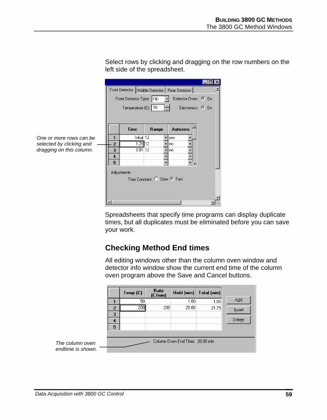
Select rows by clicking and dragging on the row numbers on the left side of the spreadsheet.
Spreadsheets that specify time programs can display duplicate times, but all duplicates must be eliminated before you can save your work.
Checking Method End times All editing windows other than the column oven window and detector info window show the current end time of the column oven program above the Save and Cancel buttons.
The column oven endtime is shown.
One or more rows can be selected by clicking and dragging on this column.
60 03-914731-00:6
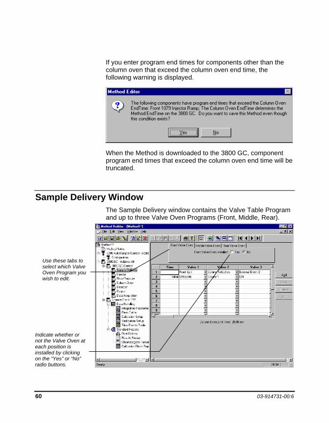
If you enter program end times for components other than the column oven that exceed the column oven end time, the following warning is displayed.
When the Method is downloaded to the 3800 GC, component program end times that exceed the column oven end time will be truncated.
Sample Delivery Window The Sample Delivery window contains the Valve Table Program and up to three Valve Oven Programs (Front, Middle, Rear).
Use these tabs to select which Valve Oven Program you wish to edit.
Indicate whether or not the Valve Oven at each position is installed by clicking on the “Yes” or “No” radio buttons.
BUILDING 3800 GC METHODS Sample Delivery Window
Data Acquisition with 3800 GC Control 61
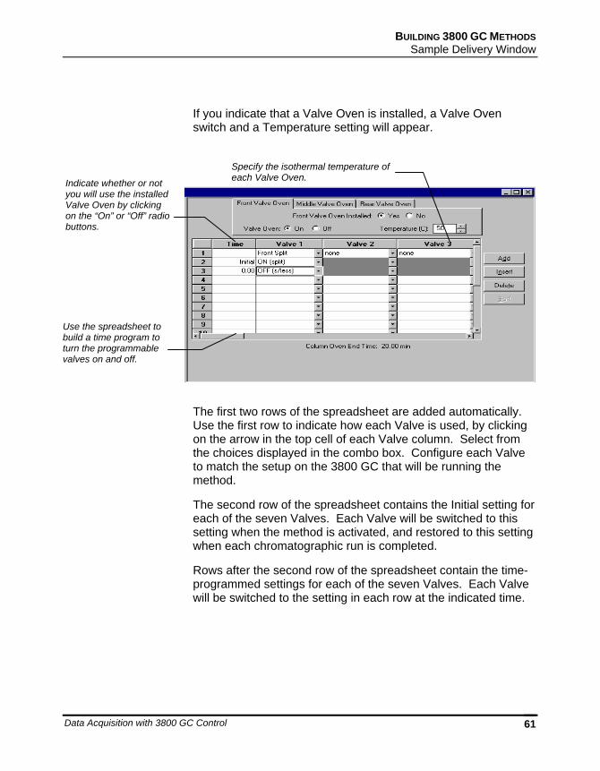
If you indicate that a Valve Oven is installed, a Valve Oven switch and a Temperature setting will appear.
The first two rows of the spreadsheet are added automatically. Use the first row to indicate how each Valve is used, by clicking on the arrow in the top cell of each Valve column. Select from the choices displayed in the combo box. Configure each Valve to match the setup on the 3800 GC that will be running the method.
The second row of the spreadsheet contains the Initial setting for each of the seven Valves. Each Valve will be switched to this setting when the method is activated, and restored to this setting when each chromatographic run is completed.
Rows after the second row of the spreadsheet contain the time-programmed settings for each of the seven Valves. Each Valve will be switched to the setting in each row at the indicated time.
Specify the isothermal temperature of each Valve Oven. Indicate whether or not
you will use the installed Valve Oven by clicking on the “On” or “Off” radio buttons.
Use the spreadsheet to build a time program to turn the programmable valves on and off.
62 03-914731-00:6
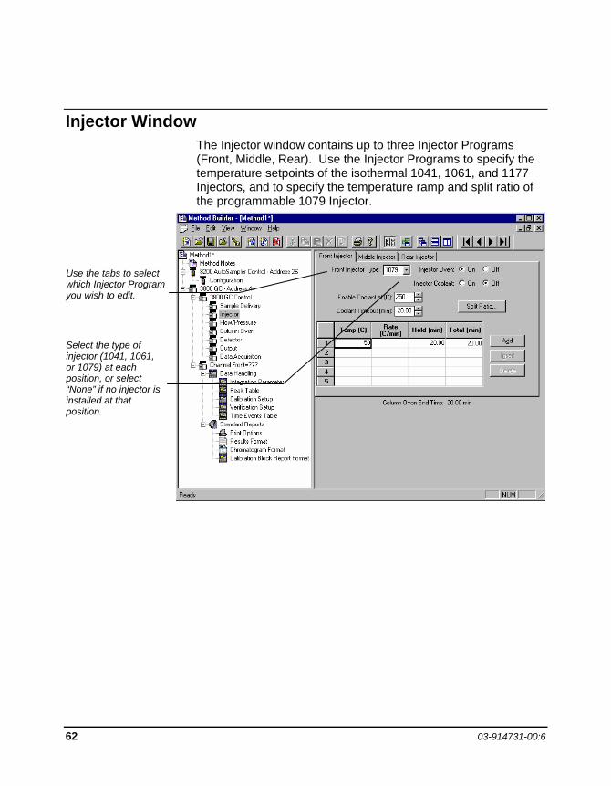
Injector Window The Injector window contains up to three Injector Programs (Front, Middle, Rear). Use the Injector Programs to specify the temperature setpoints of the isothermal 1041, 1061, and 1177 Injectors, and to specify the temperature ramp and split ratio of the programmable 1079 Injector.
Use the tabs to select which Injector Program you wish to edit.
Select the type of injector (1041, 1061, or 1079) at each position, or select “None” if no injector is installed at that position.
BUILDING 3800 GC METHODS Injector Window
Data Acquisition with 3800 GC Control 63
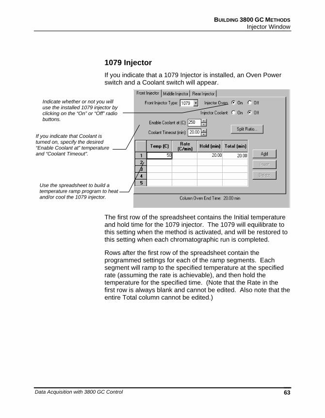
1079 Injector If you indicate that a 1079 Injector is installed, an Oven Power switch and a Coolant switch will appear.
The first row of the spreadsheet contains the Initial temperature and hold time for the 1079 injector. The 1079 will equilibrate to this setting when the method is activated, and will be restored to this setting when each chromatographic run is completed.
Rows after the first row of the spreadsheet contain the programmed settings for each of the ramp segments. Each segment will ramp to the specified temperature at the specified rate (assuming the rate is achievable), and then hold the temperature for the specified time. (Note that the Rate in the first row is always blank and cannot be edited. Also note that the entire Total column cannot be edited.)
Indicate whether or not you will use the installed 1079 injector by clicking on the “On” or “Off” radio buttons.
If you indicate that Coolant is turned on, specify the desired “Enable Coolant at” temperature and “Coolant Timeout”.
Use the spreadsheet to build a temperature ramp program to heat and/or cool the 1079 injector.
64 03-914731-00:6
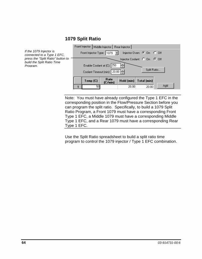
1079 Split Ratio
Note: You must have already configured the Type 1 EFC in the corresponding position in the Flow/Pressure Section before you can program the split ratio. Specifically, to build a 1079 Split Ratio Program, a Front 1079 must have a corresponding Front Type 1 EFC, a Middle 1079 must have a corresponding Middle Type 1 EFC, and a Rear 1079 must have a corresponding Rear Type 1 EFC.
Use the Split Ratio spreadsheet to build a split ratio time program to control the 1079 injector / Type 1 EFC combination.
If the 1079 Injector is connected to a Type 1 EFC, press the “Split Ratio” button to build the Split Ratio Time Program.
BUILDING 3800 GC METHODS Injector Window
Data Acquisition with 3800 GC Control 65
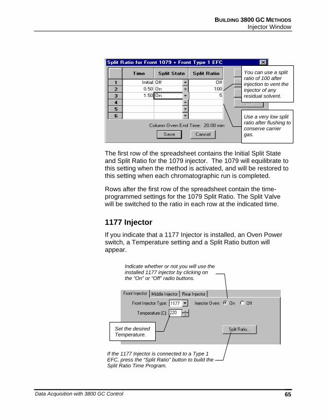
The first row of the spreadsheet contains the Initial Split State and Split Ratio for the 1079 injector. The 1079 will equilibrate to this setting when the method is activated, and will be restored to this setting when each chromatographic run is completed.
Rows after the first row of the spreadsheet contain the time-programmed settings for the 1079 Split Ratio. The Split Valve will be switched to the ratio in each row at the indicated time.
1177 Injector If you indicate that a 1177 Injector is installed, an Oven Power switch, a Temperature setting and a Split Ratio button will appear.
Indicate whether or not you will use theinstalled 1177 injector by clicking on the “On” or “Off” radio buttons.
Set the desired Temperature.
If the 1177 Injector is connected to a Type 1 EFC, press the “Split Ratio” button to build the Split Ratio Time Program.
You can use a split ratio of 100 after injection to vent the injector of any residual solvent.
Use a very low split ratio after flushing to conserve carrier gas.
66 03-914731-00:6
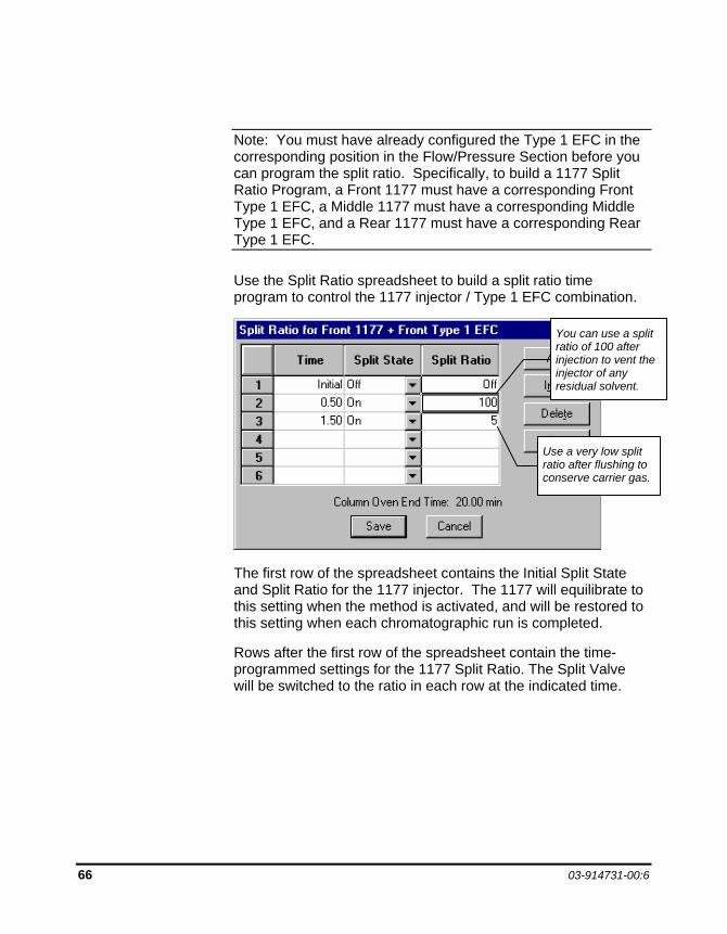
Note: You must have already configured the Type 1 EFC in the corresponding position in the Flow/Pressure Section before you can program the split ratio. Specifically, to build a 1177 Split Ratio Program, a Front 1177 must have a corresponding Front Type 1 EFC, a Middle 1177 must have a corresponding Middle Type 1 EFC, and a Rear 1177 must have a corresponding Rear Type 1 EFC.
Use the Split Ratio spreadsheet to build a split ratio time program to control the 1177 injector / Type 1 EFC combination.
The first row of the spreadsheet contains the Initial Split State and Split Ratio for the 1177 injector. The 1177 will equilibrate to this setting when the method is activated, and will be restored to this setting when each chromatographic run is completed.
Rows after the first row of the spreadsheet contain the time-programmed settings for the 1177 Split Ratio. The Split Valve will be switched to the ratio in each row at the indicated time.
You can use a split ratio of 100 after injection to vent the injector of any residual solvent.
Use a very low split ratio after flushing to conserve carrier gas.

BUILDING 3800 GC METHODS Injector Window
Data Acquisition with 3800 GC Control 67
1041 Injector If you indicate that a 1041 Injector is installed, an Oven Power switch and a Temperature setting will appear.
1061 Injector If you indicate that a 1061 Injector is installed, an Oven Power switch and a Temperature setting will appear.
Indicate whether or not you will use the installed 1041 Injector by clicking on the “On” or “Off” radio buttons.
If you indicate that a 1041 Injector is to be turned on, select the desired Temperature setting.
Indicate whether or not you will use the installed 1061 Injector by clicking on the “On” or “Off” radio buttons.
If you indicate that a 1061 Injector is to be turned on, select the desired Temperature setting.
68 03-914731-00:6
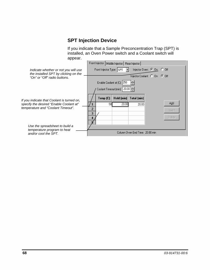
SPT Injection Device If you indicate that a Sample Preconcentration Trap (SPT) is installed, an Oven Power switch and a Coolant switch will appear.
If you indicate that Coolant is turned on, specify the desired “Enable Coolant at” temperature and “Coolant Timeout”.
Use the spreadsheet to build a temperature program to heat and/or cool the SPT.
Indicate whether or not you will use the installed SPT by clicking on the “On” or “Off” radio buttons.
BUILDING 3800 GC METHODS Flow/Pressure Window
Data Acquisition with 3800 GC Control 69
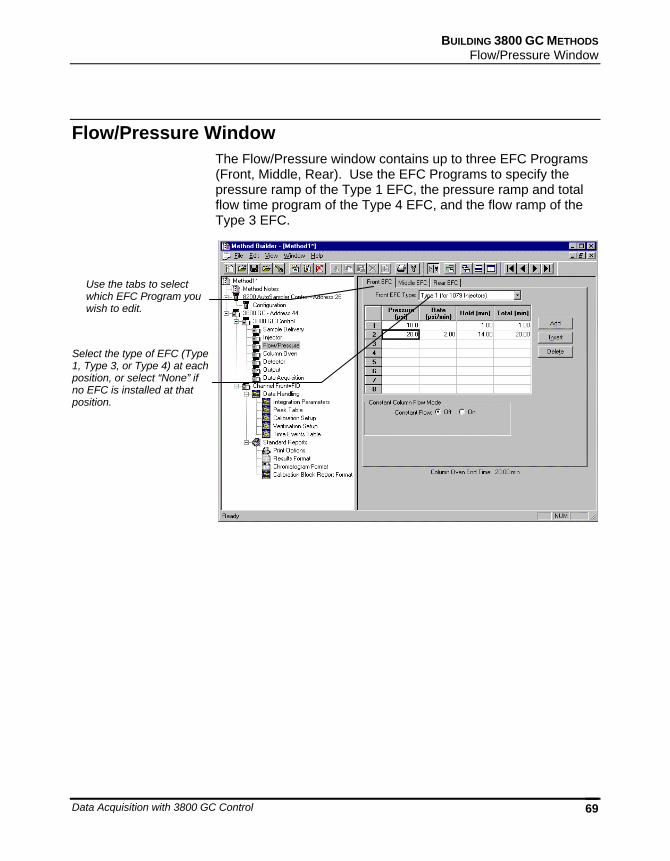
Flow/Pressure Window The Flow/Pressure window contains up to three EFC Programs (Front, Middle, Rear). Use the EFC Programs to specify the pressure ramp of the Type 1 EFC, the pressure ramp and total flow time program of the Type 4 EFC, and the flow ramp of the Type 3 EFC.
Use the tabs to select which EFC Program you wish to edit.
Select the type of EFC (Type 1, Type 3, or Type 4) at each position, or select “None” if no EFC is installed at that position.
70 03-914731-00:6
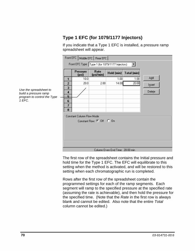
Type 1 EFC (for 1079/1177 Injectors) If you indicate that a Type 1 EFC is installed, a pressure ramp spreadsheet will appear.
The first row of the spreadsheet contains the Initial pressure and hold time for the Type 1 EFC. The EFC will equilibrate to this setting when the method is activated, and will be restored to this setting when each chromatographic run is completed.
Rows after the first row of the spreadsheet contain the programmed settings for each of the ramp segments. Each segment will ramp to the specified pressure at the specified rate (assuming the rate is achievable), and then hold the pressure for the specified time. (Note that the Rate in the first row is always blank and cannot be edited. Also note that the entire Total column cannot be edited.)
Use the spreadsheet to build a pressure ramp program to control the Type 1 EFC.
BUILDING 3800 GC METHODS Flow/Pressure Window
Data Acquisition with 3800 GC Control 71
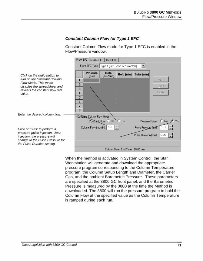
Constant Column Flow for Type 1 EFC
Constant Column Flow mode for Type 1 EFC is enabled in the Flow/Pressure window.
When the method is activated in System Control, the Star Workstation will generate and download the appropriate pressure program corresponding to the Column Temperature program, the Column Setup Length and Diameter, the Carrier Gas, and the ambient Barometric Pressure. These parameters are specified at the 3800 GC front panel, and the Barometric Pressure is measured by the 3800 at the time the Method is downloaded. The 3800 will run the pressure program to hold the Column Flow at the specified value as the Column Temperature is ramped during each run.
Click on the radio button to turn on the Constant Column Flow Mode. This mode disables the spreadsheet and reveals the constant flow rate value.
Enter the desired column flow.
Click on “Yes” to perform a pressure pulse injection. Upon injection, the pressure will change to the Pulse Pressure for the Pulse Duration setting.
72 03-914731-00:6
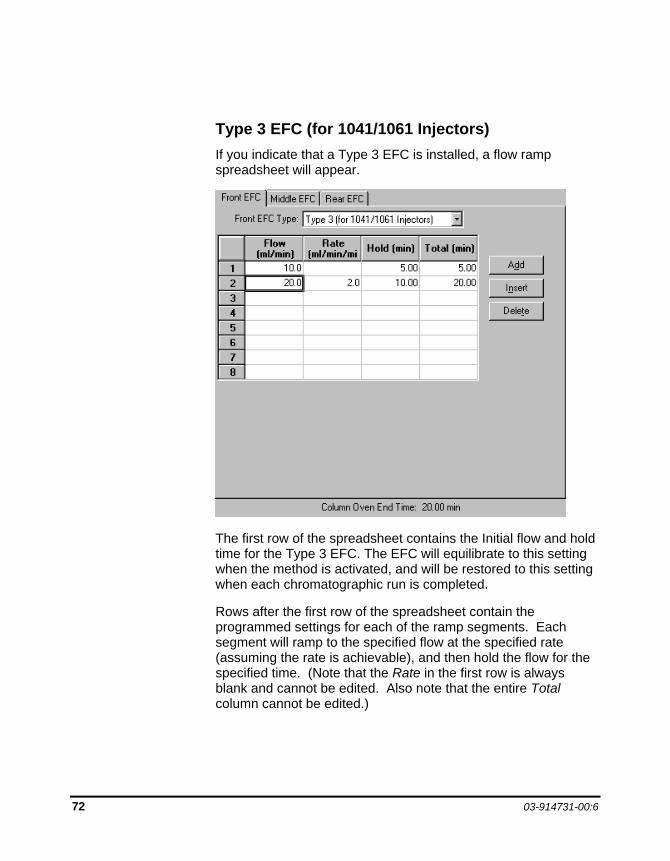
Type 3 EFC (for 1041/1061 Injectors) If you indicate that a Type 3 EFC is installed, a flow ramp spreadsheet will appear.
The first row of the spreadsheet contains the Initial flow and hold time for the Type 3 EFC. The EFC will equilibrate to this setting when the method is activated, and will be restored to this setting when each chromatographic run is completed.
Rows after the first row of the spreadsheet contain the programmed settings for each of the ramp segments. Each segment will ramp to the specified flow at the specified rate (assuming the rate is achievable), and then hold the flow for the specified time. (Note that the Rate in the first row is always blank and cannot be edited. Also note that the entire Total column cannot be edited.)
BUILDING 3800 GC METHODS Flow/Pressure Window
Data Acquisition with 3800 GC Control 73
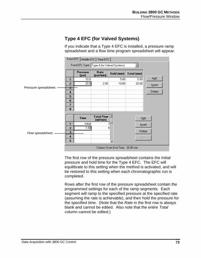
Type 4 EFC (for Valved Systems) If you indicate that a Type 4 EFC is installed, a pressure ramp spreadsheet and a flow time program spreadsheet will appear.
The first row of the pressure spreadsheet contains the Initial pressure and hold time for the Type 4 EFC. The EFC will equilibrate to this setting when the method is activated, and will be restored to this setting when each chromatographic run is completed.
Rows after the first row of the pressure spreadsheet contain the programmed settings for each of the ramp segments. Each segment will ramp to the specified pressure at the specified rate (assuming the rate is achievable), and then hold the pressure for the specified time. (Note that the Rate in the first row is always blank and cannot be edited. Also note that the entire Total column cannot be edited.)
Pressure spreadsheet.
Flow spreadsheet.
74 03-914731-00:6
Use the flow spreadsheet to build a flow time program to control the Type 4 EFC total flow. The first row of the flow spreadsheet contains the Initial Total Flow for the Type 4 EFC. The EFC will equilibrate to this setting when the method is activated, and will be restored to this setting when each chromatographic run is completed.
Rows after the first row of the flow spreadsheet contain the time-programmed settings for the Total Flow. The Total Flow will be switched to the value in each row at the indicated time.
BUILDING 3800 GC METHODS Column Oven Window
Data Acquisition with 3800 GC Control 75
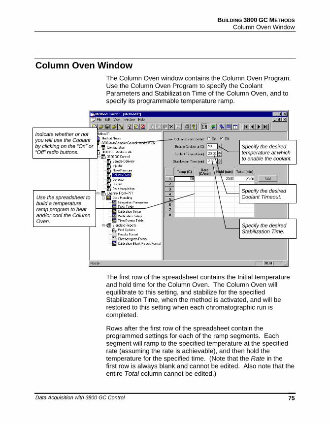
Column Oven Window The Column Oven window contains the Column Oven Program. Use the Column Oven Program to specify the Coolant Parameters and Stabilization Time of the Column Oven, and to specify its programmable temperature ramp.
The first row of the spreadsheet contains the Initial temperature and hold time for the Column Oven. The Column Oven will equilibrate to this setting, and stabilize for the specified Stabilization Time, when the method is activated, and will be restored to this setting when each chromatographic run is completed.
Rows after the first row of the spreadsheet contain the programmed settings for each of the ramp segments. Each segment will ramp to the specified temperature at the specified rate (assuming the rate is achievable), and then hold the temperature for the specified time. (Note that the Rate in the first row is always blank and cannot be edited. Also note that the entire Total column cannot be edited.)
Indicate whether or not you will use the Coolant by clicking on the “On” or “Off” radio buttons.
Specify the desired temperature at which to enable the coolant.
Specify the desired Coolant Timeout.
Specify the desired Stabilization Time.
Use the spreadsheet to build a temperature ramp program to heat and/or cool the Column Oven.
76 03-914731-00:6
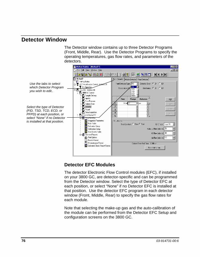
Detector Window The Detector window contains up to three Detector Programs (Front, Middle, Rear). Use the Detector Programs to specify the operating temperatures, gas flow rates, and parameters of the detectors.
Detector EFC Modules The detector Electronic Flow Control modules (EFC), if installed on your 3800 GC, are detector-specific and can be programmed from the Detector window. Select the type of Detector EFC at each position, or select “None” if no Detector EFC is installed at that position. Use the detector EFC program in each detector window (Front, Middle, Rear) to specify the gas flow rates for each module.
Note that selecting the make-up gas and the auto-calibration of the module can be performed from the Detector EFC Setup and configuration screens on the 3800 GC.
Use the tabs to select which Detector Program you wish to edit..
Select the type of Detector (FID, TSD, TCD, ECD, or PFPD) at each position, or select “None” if no Detector is installed at that position.
BUILDING 3800 GC METHODS Detector Window
Data Acquisition with 3800 GC Control 77
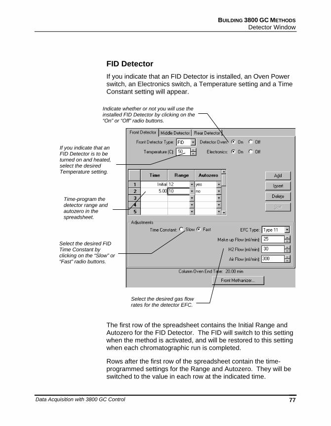
FID Detector If you indicate that an FID Detector is installed, an Oven Power switch, an Electronics switch, a Temperature setting and a Time Constant setting will appear.
The first row of the spreadsheet contains the Initial Range and Autozero for the FID Detector. The FID will switch to this setting when the method is activated, and will be restored to this setting when each chromatographic run is completed.
Rows after the first row of the spreadsheet contain the time-programmed settings for the Range and Autozero. They will be switched to the value in each row at the indicated time.
If you indicate that an FID Detector is to be turned on and heated, select the desired Temperature setting.
Time-program the detector range and autozero in the spreadsheet.
Select the desired FID Time Constant by clicking on the “Slow” or “Fast” radio buttons.
Select the desired gas flow rates for the detector EFC.
Indicate whether or not you will use the installed FID Detector by clicking on the “On” or “Off” radio buttons.
78 03-914731-00:6
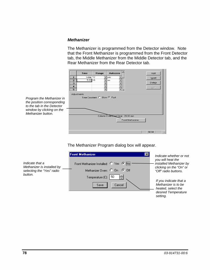
Methanizer
The Methanizer is programmed from the Detector window. Note that the Front Methanizer is programmed from the Front Detector tab, the Middle Methanizer from the Middle Detector tab, and the Rear Methanizer from the Rear Detector tab.
The Methanizer Program dialog box will appear.
Program the Methanizer in the position corresponding to the tab in the Detector window by clicking on the Methanizer button.
Indicate that a Methanizer is installed by selecting the “Yes” radio button.
Indicate whether or not you will heat the installed Methanizer by clicking on the “On” or “Off” radio buttons.
If you indicate that a Methanizer is to be heated, select the desired Temperature setting.
BUILDING 3800 GC METHODS Detector Window
Data Acquisition with 3800 GC Control 79
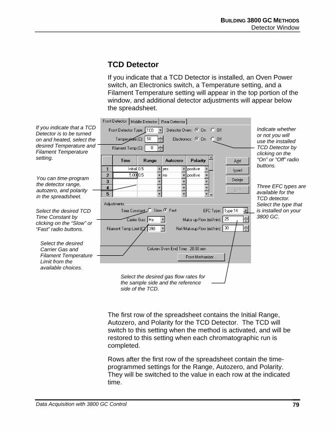
TCD Detector If you indicate that a TCD Detector is installed, an Oven Power switch, an Electronics switch, a Temperature setting, and a Filament Temperature setting will appear in the top portion of the window, and additional detector adjustments will appear below the spreadsheet.
The first row of the spreadsheet contains the Initial Range, Autozero, and Polarity for the TCD Detector. The TCD will switch to this setting when the method is activated, and will be restored to this setting when each chromatographic run is completed.
Rows after the first row of the spreadsheet contain the time-programmed settings for the Range, Autozero, and Polarity. They will be switched to the value in each row at the indicated time.
Indicate whether or not you will use the installed TCD Detector by clicking on the “On” or “Off” radio buttons.
If you indicate that a TCD Detector is to be turned on and heated, select the desired Temperature and Filament Temperature setting.
You can time-program the detector range, autozero, and polarity in the spreadsheet.
Select the desired TCD Time Constant by clicking on the “Slow” or “Fast” radio buttons.
Select the desired Carrier Gas and Filament Temperature Limit from the available choices.
Select the desired gas flow rates for the sample side and the reference side of the TCD.
Three EFC types are available for the TCD detector. Select the type that is installed on your 3800 GC.
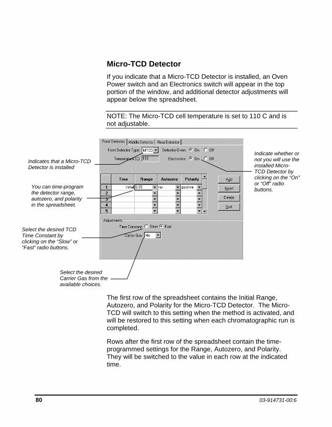
80 03-914731-00:6
Micro-TCD Detector If you indicate that a Micro-TCD Detector is installed, an Oven Power switch and an Electronics switch will appear in the top portion of the window, and additional detector adjustments will appear below the spreadsheet.
NOTE: The Micro-TCD cell temperature is set to 110 C and is not adjustable.
The first row of the spreadsheet contains the Initial Range, Autozero, and Polarity for the Micro-TCD Detector. The Micro-TCD will switch to this setting when the method is activated, and will be restored to this setting when each chromatographic run is completed.
Rows after the first row of the spreadsheet contain the time-programmed settings for the Range, Autozero, and Polarity. They will be switched to the value in each row at the indicated time.
Indicate whether or not you will use the installed Micro-TCD Detector by clicking on the “On” or “Off” radio buttons.
Indicates that a Micro-TCD Detector is installed
You can time-program the detector range, autozero, and polarity in the spreadsheet.
Select the desired TCD Time Constant by clicking on the “Slow” or “Fast” radio buttons.
Select the desired Carrier Gas from the available choices.
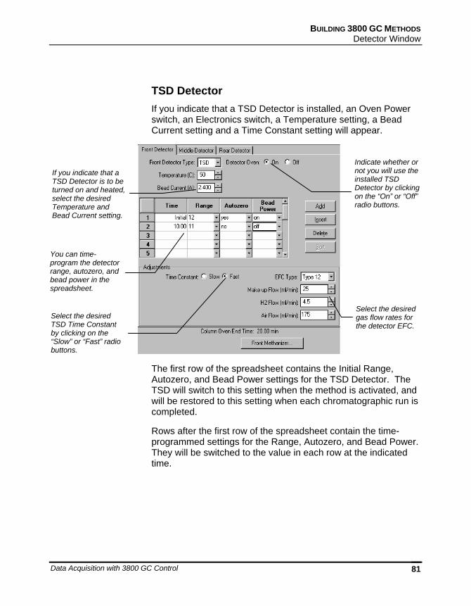
BUILDING 3800 GC METHODS Detector Window
Data Acquisition with 3800 GC Control 81
TSD Detector If you indicate that a TSD Detector is installed, an Oven Power switch, an Electronics switch, a Temperature setting, a Bead Current setting and a Time Constant setting will appear.
The first row of the spreadsheet contains the Initial Range, Autozero, and Bead Power settings for the TSD Detector. The TSD will switch to this setting when the method is activated, and will be restored to this setting when each chromatographic run is completed.
Rows after the first row of the spreadsheet contain the time-programmed settings for the Range, Autozero, and Bead Power. They will be switched to the value in each row at the indicated time.
Indicate whether or not you will use the installed TSD Detector by clicking on the “On” or “Off” radio buttons.
If you indicate that a TSD Detector is to be turned on and heated, select the desired Temperature and Bead Current setting.
You can time-program the detector range, autozero, and bead power in the spreadsheet.
Select the desired TSD Time Constant by clicking on the “Slow” or “Fast” radio buttons.
Select the desired gas flow rates for the detector EFC.
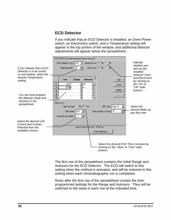
82 03-914731-00:6
ECD Detector If you indicate that an ECD Detector is installed, an Oven Power switch, an Electronics switch, and a Temperature setting will appear in the top portion of the window, and additional detector adjustments will appear below the spreadsheet.
The first row of the spreadsheet contains the Initial Range and Autozero for the ECD Detector. The ECD will switch to this setting when the method is activated, and will be restored to this setting when each chromatographic run is completed.
Rows after the first row of the spreadsheet contain the time-programmed settings for the Range and Autozero. They will be switched to the value in each row at the indicated time.
Indicate whether you will use the installed Detector Oven and Electronics by clicking on the “On” or “Off” radio buttons.
You can time-program the detector range and autozero in the spreadsheet.
Select the desired Cell Current and Contact Potential from the available choices.
Select the desired Make up gas flow rate.
Select the desired ECD Time Constant by clicking on the “Slow” or “Fast” radio buttons.
If you indicate that a ECD Detector is to be turned on and heated, select the desired Temperature setting.
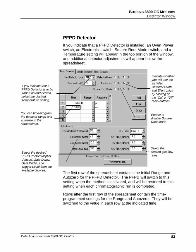
BUILDING 3800 GC METHODS Detector Window
Data Acquisition with 3800 GC Control 83
PFPD Detector If you indicate that a PFPD Detector is installed, an Oven Power switch, an Electronics switch, Square Root Mode switch, and a Temperature setting will appear in the top portion of the window, and additional detector adjustments will appear below the spreadsheet.
The first row of the spreadsheet contains the Initial Range and Autozero for the PFPD Detector. The PFPD will switch to this setting when the method is activated, and will be restored to this setting when each chromatographic run is completed.
Rows after the first row of the spreadsheet contain the time-programmed settings for the Range and Autozero. They will be switched to the value in each row at the indicated time.
Indicate whether you will use the installed Detector Oven and Electronics by clicking on the “On” or “Off” radio buttons.
If you indicate that a PFPD Detector is to be turned on and heated, select the desired Temperature setting.
You can time-program the detector range and autozero in the spreadsheet.
Select the desired PFPD Photomultiplier Voltage, Gate Delay, Gate Width, and Trigger Level from the available choices.
Enable or disable Square Root Mode.
Select the desired gas flow rates.
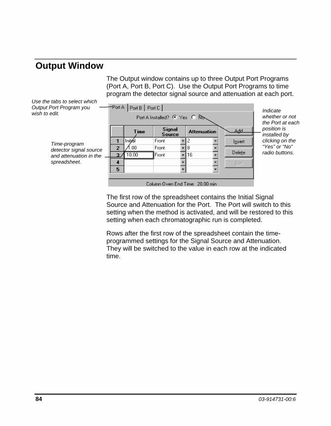
84 03-914731-00:6
Output Window The Output window contains up to three Output Port Programs (Port A, Port B, Port C). Use the Output Port Programs to time program the detector signal source and attenuation at each port.
The first row of the spreadsheet contains the Initial Signal Source and Attenuation for the Port. The Port will switch to this setting when the method is activated, and will be restored to this setting when each chromatographic run is completed.
Rows after the first row of the spreadsheet contain the time-programmed settings for the Signal Source and Attenuation. They will be switched to the value in each row at the indicated time.
Indicate whether or not the Port at each position is installed by clicking on the “Yes” or “No” radio buttons.
Time-program detector signal source and attenuation in the spreadsheet.
Use the tabs to select which Output Port Program you wish to edit.
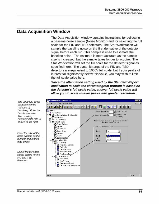
BUILDING 3800 GC METHODS Data Acquisition Window
Data Acquisition with 3800 GC Control 85
Data Acquisition Window The Data Acquisition window contains instructions for collecting a baseline noise sample (Noise Monitor) and for selecting the full scale for the FID and TSD detectors. The Star Workstation will sample the baseline noise on the first derivative of the detector signal before each run. This sample is used to estimate the baseline noise. The estimate is more accurate as the sample size is increased, but the sample takes longer to acquire. The Star Workstation will set the full scale for the detector signal as specified here. The dynamic range of the FID and TSD detectors are equivalent to 1000V full scale, but if your peaks of interest fall significantly below this value, you may wish to limit the full scale value here. Since the attenuation setting used by the Standard Report application to scale the chromatogram printout is based on the detector's full scale value, a lower full scale value will allow you to scale smaller peaks with greater resolution.
Enter the size of the noise sample as the number of bunched data points.
Select the full scale signal setting for the FID and TSD detectors.
The 3800 GC 40 Hz data rate can be reduced by bunching. Enter the bunch size here. The resulting bunched data rate is shown to the right.
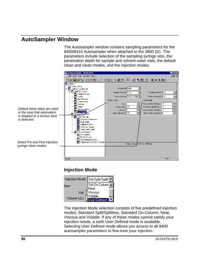
86 03-914731-00:6
AutoSampler Window The Autosampler window contains sampling parameters for the 8400/8410 Autosampler when attached to the 3800 GC. The parameters include selection of the sampling syringe size, the penetration depth for sample and solvent wash vials, the default clean and clean modes, and the injection modes.
Injection Mode
The Injection Mode selection consists of five predefined injection modes: Standard Split/Splitless, Standard On-Column, Neat, Viscous and Volatile. If any of these modes cannot satisfy your injection needs, a sixth User Defined mode is available. Selecting User Defined mode allows you access to all 8400 autosampler parameters to fine-tune your injection.
Default clean steps are used in the case that automation is stopped or a serious fault is detected.
Select Pre and Post injection syringe clean modes.
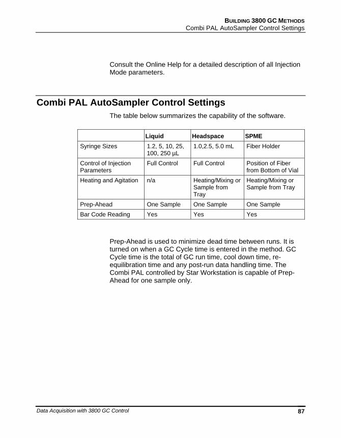
BUILDING 3800 GC METHODS Combi PAL AutoSampler Control Settings
Data Acquisition with 3800 GC Control 87
Consult the Online Help for a detailed description of all Injection Mode parameters.
Combi PAL AutoSampler Control Settings The table below summarizes the capability of the software.
Liquid Headspace SPME Syringe Sizes 1.2, 5, 10, 25,
100, 250 µL 1.0,2.5, 5.0 mL Fiber Holder
Control of Injection Parameters
Full Control Full Control Position of Fiber from Bottom of Vial
Heating and Agitation n/a Heating/Mixing or Sample from Tray
Heating/Mixing or Sample from Tray
Prep-Ahead One Sample One Sample One Sample Bar Code Reading Yes Yes Yes
Prep-Ahead is used to minimize dead time between runs. It is turned on when a GC Cycle time is entered in the method. GC Cycle time is the total of GC run time, cool down time, re-equilibration time and any post-run data handling time. The Combi PAL controlled by Star Workstation is capable of Prep-Ahead for one sample only.
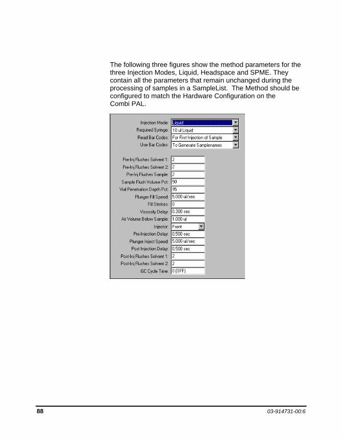
88 03-914731-00:6
The following three figures show the method parameters for the three Injection Modes, Liquid, Headspace and SPME. They contain all the parameters that remain unchanged during the processing of samples in a SampleList. The Method should be configured to match the Hardware Configuration on the Combi PAL.
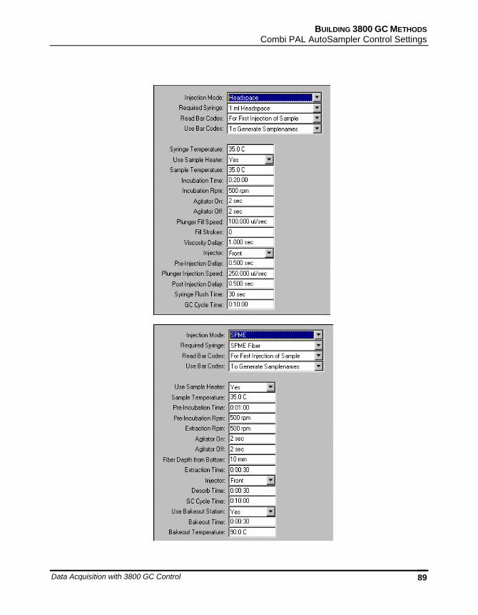
BUILDING 3800 GC METHODS Combi PAL AutoSampler Control Settings
Data Acquisition with 3800 GC Control 89
90 03-914731-00:6
Barcode Reader
The barcode reader can be used in two modes: To Generate Sample Names (barcode is entered in Sample List) and To Validate Sample Names(barcode is checked against the Sample List).
If the barcode reader is used to generate sample names, the user should leave the sample name column in the Sample List blank. Any pre-existed sample names in the sample list will be overwritten by the barcodes read by the barcode reader. If the barcode cannot be read, the pre-existed sample name will be retained and an error will be generated.
If the barcode reader is used to validate sample names, the user should enter sample names in the sample list. If the name on the barcode label read by the barcode reader differs from the name the user enters into the Sample List, or if the barcode cannot be read, the name in the Sample List will be retained. An error will be generated. If the user does not enter names in the Sample List, an error will be generated whether or not the barcode label can be read. The barcode name will not be entered into the Sample List.
The user will specify how many errors are allowed before a run sequence is aborted. The "Max Errors" is entered in the dialog box for "Instrument Parameters" that appears when sample injection is called out.
For a detailed description of all other Combi PAL AutoSampler Method Builder parameters, please refer to the online help in Method Builder.
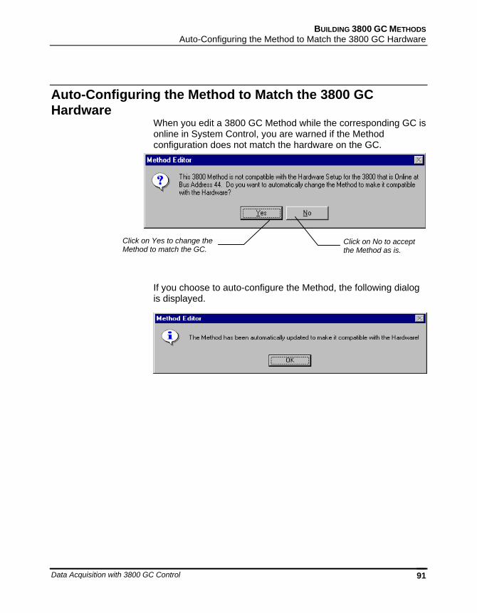
BUILDING 3800 GC METHODS Auto-Configuring the Method to Match the 3800 GC Hardware
Data Acquisition with 3800 GC Control 91
Auto-Configuring the Method to Match the 3800 GC Hardware
When you edit a 3800 GC Method while the corresponding GC is online in System Control, you are warned if the Method configuration does not match the hardware on the GC.
If you choose to auto-configure the Method, the following dialog is displayed.
Click on Yes to change the Method to match the GC.
Click on No to accept the Method as is.
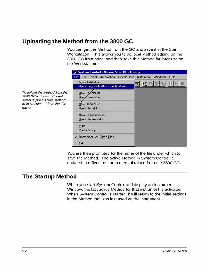
92 03-914731-00:6
Uploading the Method from the 3800 GC You can get the Method from the GC and save it in the Star Workstation. This allows you to do local Method editing on the 3800 GC front panel and then save this Method for later use on the Workstation.
You are then prompted for the name of the file under which to save the Method. The active Method in System Control is updated to reflect the parameters obtained from the 3800 GC.
The Startup Method When you start System Control and display an Instrument Window, the last active Method for that instrument is activated. When System Control is started, it will return to the initial settings in the Method that was last used on the instrument.
To upload the Method from the 3800 GC to System Control, select “Upload Active Method from Modules…” from the File menu.
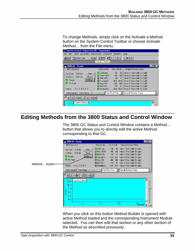
BUILDING 3800 GC METHODS Editing Methods from the 3800 Status and Control Window
Data Acquisition with 3800 GC Control 93
To change Methods, simply click on the Activate a Method button on the System Control Toolbar or choose Activate Method… from the File menu.
Editing Methods from the 3800 Status and Control Window The 3800 GC Status and Control Window contains a Method… button that allows you to directly edit the active Method corresponding to that GC.
When you click on this button Method Builder is opened with active Method loaded and the corresponding Instrument Module selected. You can then edit that section or any other section of the Method as described previously.
Method… button
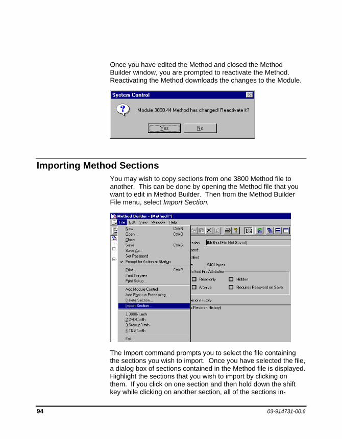
94 03-914731-00:6
Once you have edited the Method and closed the Method Builder window, you are prompted to reactivate the Method. Reactivating the Method downloads the changes to the Module.
Importing Method Sections You may wish to copy sections from one 3800 Method file to another. This can be done by opening the Method file that you want to edit in Method Builder. Then from the Method Builder File menu, select Import Section.
The Import command prompts you to select the file containing the sections you wish to import. Once you have selected the file, a dialog box of sections contained in the Method file is displayed. Highlight the sections that you wish to import by clicking on them. If you click on one section and then hold down the shift key while clicking on another section, all of the sections in-
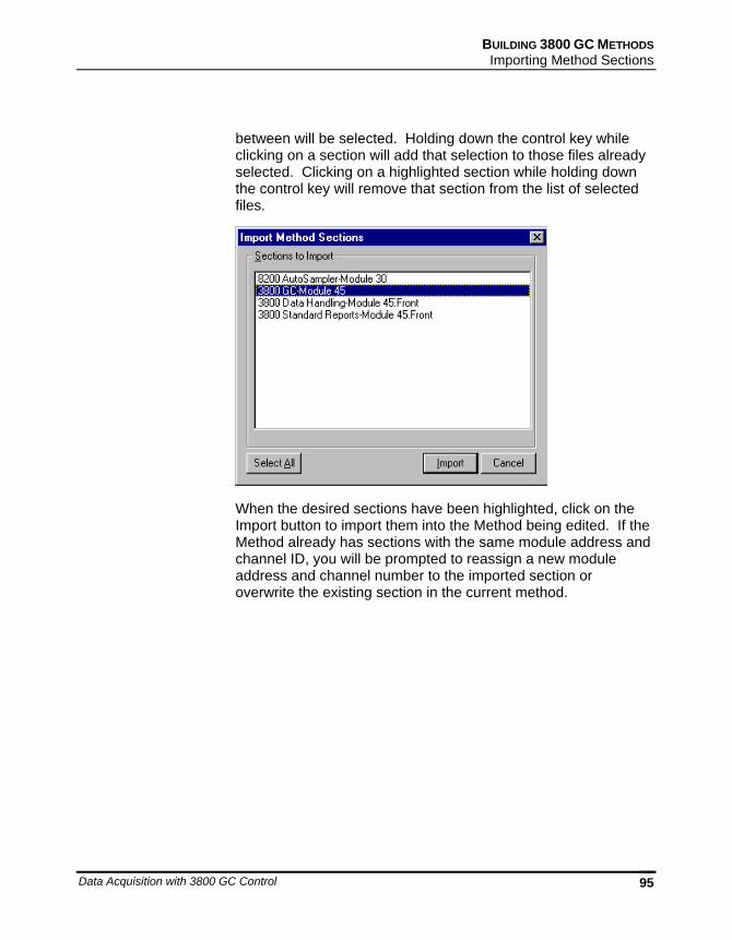
BUILDING 3800 GC METHODS Importing Method Sections
Data Acquisition with 3800 GC Control 95
between will be selected. Holding down the control key while clicking on a section will add that selection to those files already selected. Clicking on a highlighted section while holding down the control key will remove that section from the list of selected files.
When the desired sections have been highlighted, click on the Import button to import them into the Method being edited. If the Method already has sections with the same module address and channel ID, you will be prompted to reassign a new module address and channel number to the imported section or overwrite the existing section in the current method.
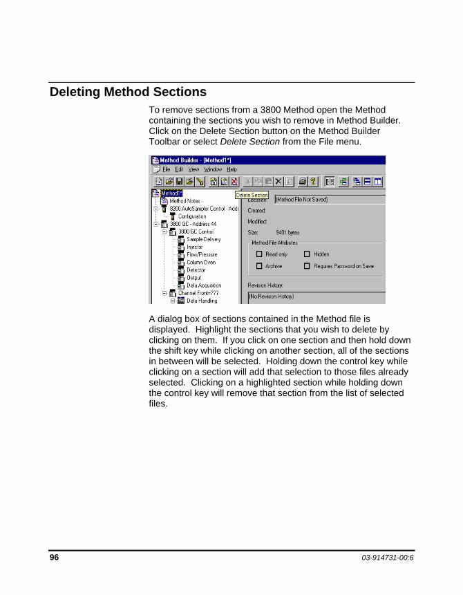
96 03-914731-00:6
Deleting Method Sections To remove sections from a 3800 Method open the Method containing the sections you wish to remove in Method Builder. Click on the Delete Section button on the Method Builder Toolbar or select Delete Section from the File menu.
A dialog box of sections contained in the Method file is displayed. Highlight the sections that you wish to delete by clicking on them. If you click on one section and then hold down the shift key while clicking on another section, all of the sections in between will be selected. Holding down the control key while clicking on a section will add that selection to those files already selected. Clicking on a highlighted section while holding down the control key will remove that section from the list of selected files.
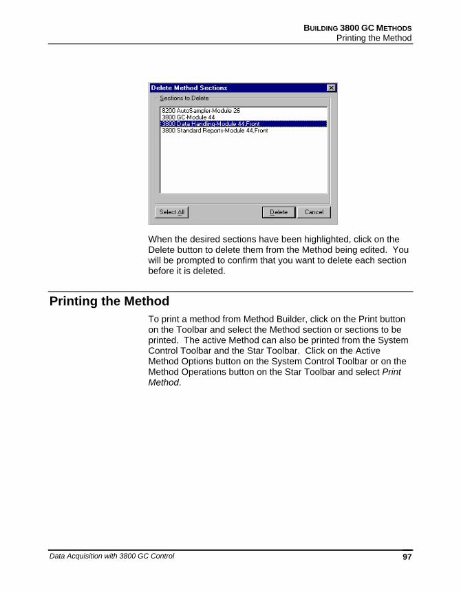
BUILDING 3800 GC METHODS Printing the Method
Data Acquisition with 3800 GC Control 97
When the desired sections have been highlighted, click on the Delete button to delete them from the Method being edited. You will be prompted to confirm that you want to delete each section before it is deleted.
Printing the Method To print a method from Method Builder, click on the Print button on the Toolbar and select the Method section or sections to be printed. The active Method can also be printed from the System Control Toolbar and the Star Toolbar. Click on the Active Method Options button on the System Control Toolbar or on the Method Operations button on the Star Toolbar and select Print Method.
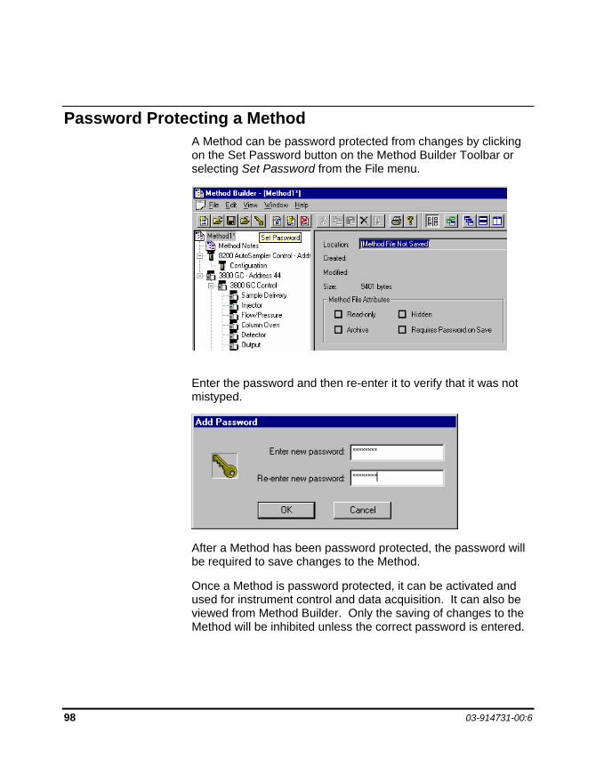
98 03-914731-00:6
Password Protecting a Method A Method can be password protected from changes by clicking on the Set Password button on the Method Builder Toolbar or selecting Set Password from the File menu.
Enter the password and then re-enter it to verify that it was not mistyped.
After a Method has been password protected, the password will be required to save changes to the Method.
Once a Method is password protected, it can be activated and used for instrument control and data acquisition. It can also be viewed from Method Builder. Only the saving of changes to the Method will be inhibited unless the correct password is entered.
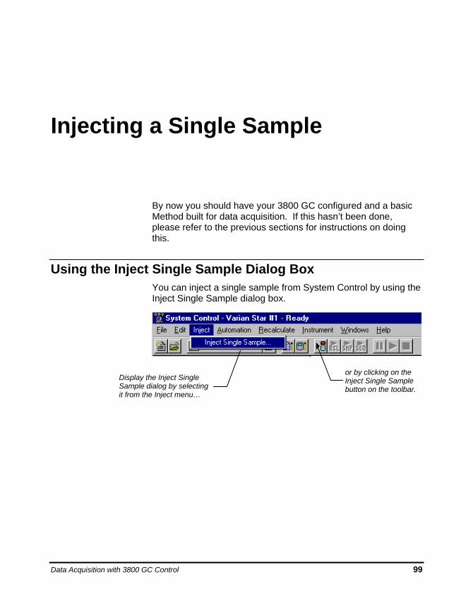
Data Acquisition with 3800 GC Control 99
Injecting a Single Sample
By now you should have your 3800 GC configured and a basic Method built for data acquisition. If this hasn’t been done, please refer to the previous sections for instructions on doing this.
Using the Inject Single Sample Dialog Box You can inject a single sample from System Control by using the Inject Single Sample dialog box.
Display the Inject Single Sample dialog by selecting it from the Inject menu…
or by clicking on the Inject Single Sample button on the toolbar.
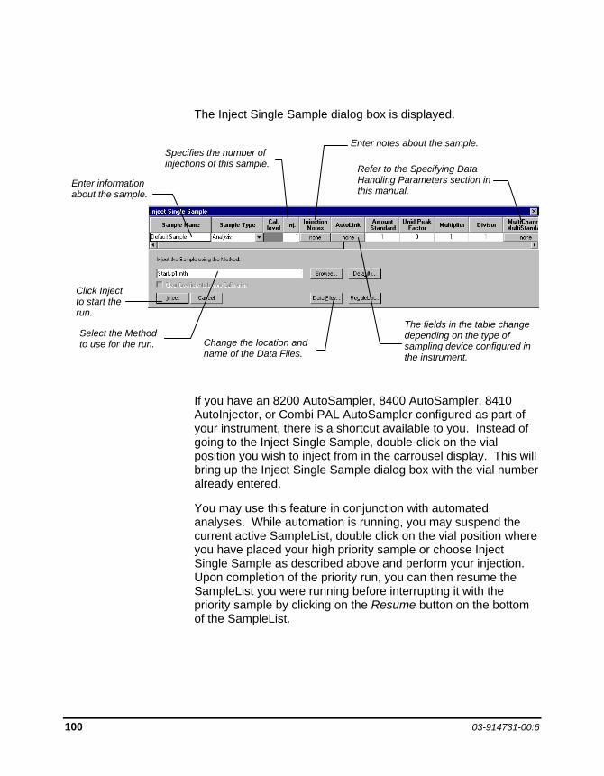
100 03-914731-00:6
The Inject Single Sample dialog box is displayed.
If you have an 8200 AutoSampler, 8400 AutoSampler, 8410 AutoInjector, or Combi PAL AutoSampler configured as part of your instrument, there is a shortcut available to you. Instead of going to the Inject Single Sample, double-click on the vial position you wish to inject from in the carrousel display. This will bring up the Inject Single Sample dialog box with the vial number already entered.
You may use this feature in conjunction with automated analyses. While automation is running, you may suspend the current active SampleList, double click on the vial position where you have placed your high priority sample or choose Inject Single Sample as described above and perform your injection. Upon completion of the priority run, you can then resume the SampleList you were running before interrupting it with the priority sample by clicking on the Resume button on the bottom of the SampleList.
The fields in the table change depending on the type of sampling device configured in the instrument.
Enter information about the sample.
Select the Method to use for the run.
Click Inject to start the run.
Change the location and name of the Data Files.
Refer to the Specifying Data Handling Parameters section in this manual.
Enter notes about the sample. Specifies the number of injections of this sample.
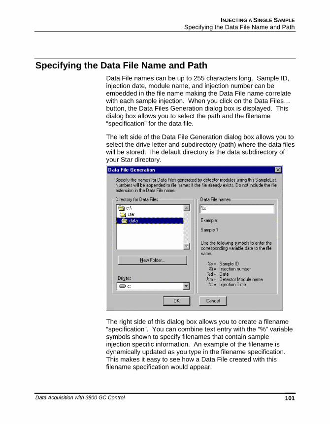
INJECTING A SINGLE SAMPLE Specifying the Data File Name and Path
Data Acquisition with 3800 GC Control 101
Specifying the Data File Name and Path Data File names can be up to 255 characters long. Sample ID, injection date, module name, and injection number can be embedded in the file name making the Data File name correlate with each sample injection. When you click on the Data Files… button, the Data Files Generation dialog box is displayed. This dialog box allows you to select the path and the filename “specification” for the data file.
The left side of the Data File Generation dialog box allows you to select the drive letter and subdirectory (path) where the data files will be stored. The default directory is the data subdirectory of your Star directory.
The right side of this dialog box allows you to create a filename “specification”. You can combine text entry with the “%” variable symbols shown to specify filenames that contain sample injection specific information. An example of the filename is dynamically updated as you type in the filename specification. This makes it easy to see how a Data File created with this filename specification would appear.
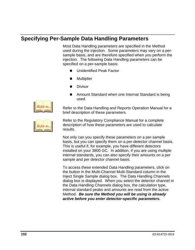
102 03-914731-00:6
Specifying Per-Sample Data Handling Parameters Most Data Handling parameters are specified in the Method used during the injection. Some parameters may vary on a per-sample basis, and are therefore specified when you perform the injection. The following Data Handling parameters can be specified on a per-sample basis:
Unidentified Peak Factor
Multiplier
Divisor
Amount Standard when one Internal Standard is being used.
Refer to the Data Handling and Reports Operation Manual for a brief description of these parameters.
Refer to the Regulatory Compliance Manual for a complete description of how these parameters are used to calculate results.
Not only can you specify these parameters on a per-sample basis, but you can specify them on a per-detector channel basis. This is useful if, for example, you have different detectors installed on your 3800 GC. In addition, if you are using multiple internal standards, you can also specify their amounts on a per sample and per detector channel basis.
To access these extended Data Handling parameters, click on the button in the Multi-Channel Multi-Standard column in the Inject Single Sample dialog box. The Data Handling Channels dialog box is displayed. When you select the detector channel in the Data Handling Channels dialog box, the calculation type, internal standard peaks and amounts are read from the active Method. Be sure the Method you will be using is already active before you enter detector-specific parameters.
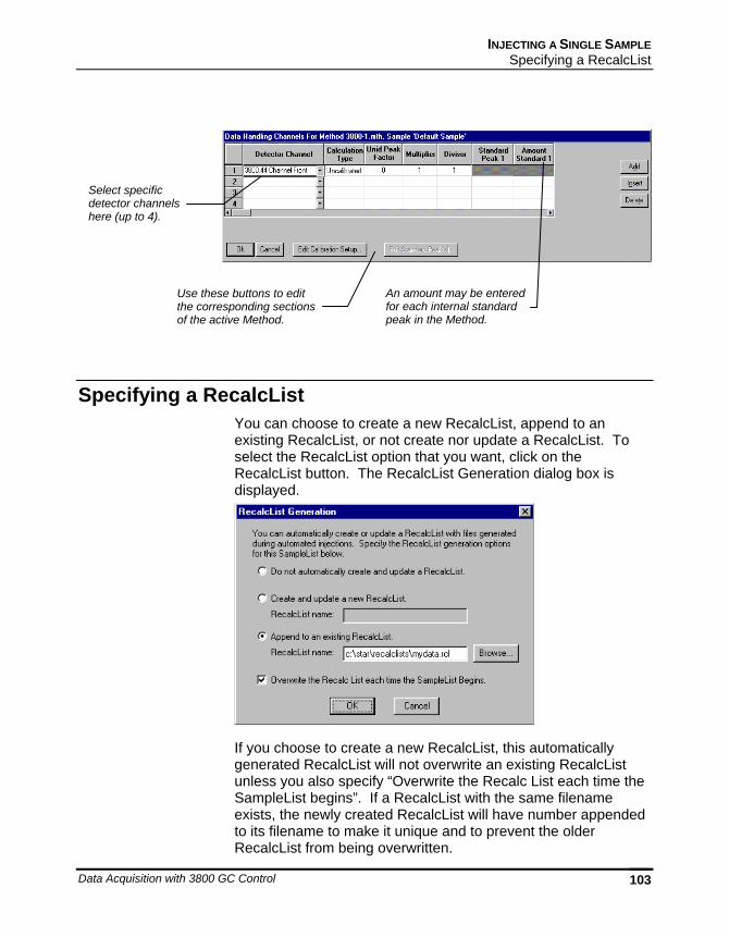
INJECTING A SINGLE SAMPLE Specifying a RecalcList
Data Acquisition with 3800 GC Control 103
Specifying a RecalcList You can choose to create a new RecalcList, append to an existing RecalcList, or not create nor update a RecalcList. To select the RecalcList option that you want, click on the RecalcList button. The RecalcList Generation dialog box is displayed.
If you choose to create a new RecalcList, this automatically generated RecalcList will not overwrite an existing RecalcList unless you also specify “Overwrite the Recalc List each time the SampleList begins”. If a RecalcList with the same filename exists, the newly created RecalcList will have number appended to its filename to make it unique and to prevent the older RecalcList from being overwritten.
Select specific detector channels here (up to 4).
An amount may be entered for each internal standard peak in the Method.
Use these buttons to edit the corresponding sections of the active Method.
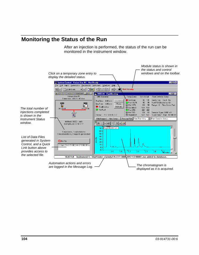
104 03-914731-00:6
Monitoring the Status of the Run After an injection is performed, the status of the run can be monitored in the instrument window.
Click on a temporary zone entry to display the detailed status.
The total number of injections completed is shown in the Instrument Status window.
The chromatogram is displayed as it is acquired.
List of Data Files generated in System Control, and a Quick Link button above provides access to the selected file.
Automation actions and errors are logged in the Message Log.
Module status is shown in the status and control windows and on the toolbar.
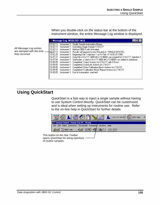
INJECTING A SINGLE SAMPLE Using QuickStart
Data Acquisition with 3800 GC Control 105
When you double-click on the status bar at the bottom of the instrument window, the entire Message Log window is displayed.
Using QuickStart QuickStart is a fast way to inject a single sample without having to use System Control directly. QuickStart can be customized and is ideal when setting up instruments for routine use. Refer to the on-line help in QuickStart for further details.
All Message Log entries are stamped with the time they occurred.
This button on the Star Toolbar opens QuickStart for doing injections of routine samples.
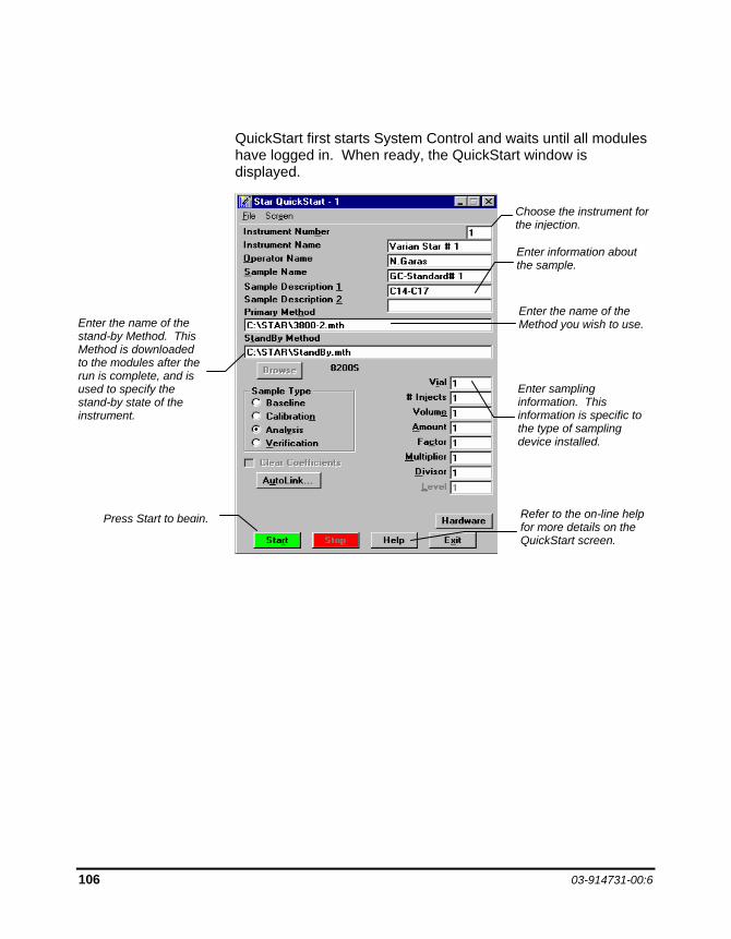
106 03-914731-00:6
QuickStart first starts System Control and waits until all modules have logged in. When ready, the QuickStart window is displayed.
Choose the instrument for the injection.
Enter information about the sample.
Enter sampling information. This information is specific to the type of sampling device installed.
Enter the name of the Method you wish to use. Enter the name of the
stand-by Method. This Method is downloaded to the modules after the run is complete, and is used to specify the stand-by state of the instrument.
Press Start to begin. Refer to the on-line help for more details on the QuickStart screen.
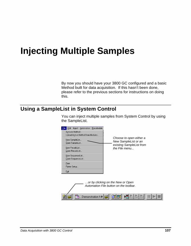
Data Acquisition with 3800 GC Control 107
Injecting Multiple Samples
By now you should have your 3800 GC configured and a basic Method built for data acquisition. If this hasn’t been done, please refer to the previous sections for instructions on doing this.
Using a SampleList in System Control You can inject multiple samples from System Control by using the SampleList.
Choose to open either a New SampleList or an existing SampleList from the File menu...
…or by clicking on the New or Open Automation File button on the toolbar.
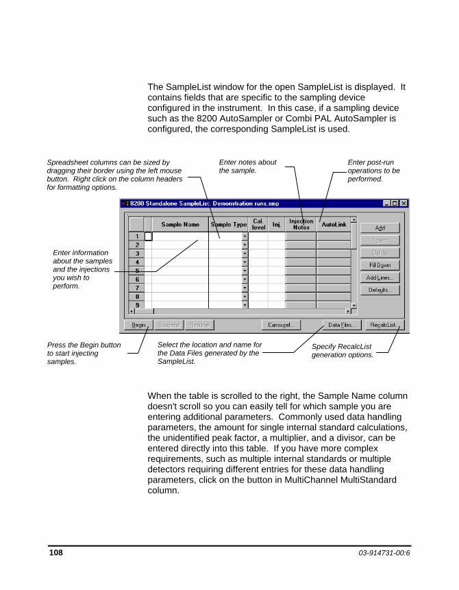
108 03-914731-00:6
The SampleList window for the open SampleList is displayed. It contains fields that are specific to the sampling device configured in the instrument. In this case, if a sampling device such as the 8200 AutoSampler or Combi PAL AutoSampler is configured, the corresponding SampleList is used.
When the table is scrolled to the right, the Sample Name column doesn't scroll so you can easily tell for which sample you are entering additional parameters. Commonly used data handling parameters, the amount for single internal standard calculations, the unidentified peak factor, a multiplier, and a divisor, can be entered directly into this table. If you have more complex requirements, such as multiple internal standards or multiple detectors requiring different entries for these data handling parameters, click on the button in MultiChannel MultiStandard column.
Enter information about the samples and the injections you wish to perform.
Select the location and name for the Data Files generated by the SampleList.
Press the Begin button to start injecting samples.
Enter notes about the sample.
Enter post-run operations to be performed.
Specify RecalcList generation options.
Spreadsheet columns can be sized by dragging their border using the left mouse button. Right click on the column headers for formatting options.
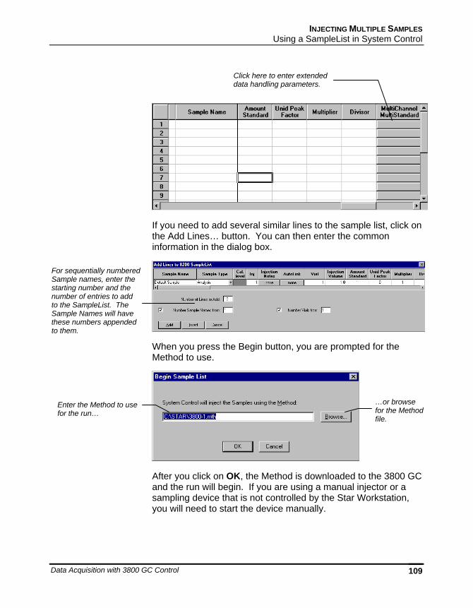
INJECTING MULTIPLE SAMPLES Using a SampleList in System Control
Data Acquisition with 3800 GC Control 109
If you need to add several similar lines to the sample list, click on the Add Lines… button. You can then enter the common information in the dialog box.
When you press the Begin button, you are prompted for the Method to use.
After you click on OK, the Method is downloaded to the 3800 GC and the run will begin. If you are using a manual injector or a sampling device that is not controlled by the Star Workstation, you will need to start the device manually.
Enter the Method to use for the run…
…or browse for the Method file.
For sequentially numbered Sample names, enter the starting number and the number of entries to add to the SampleList. The Sample Names will have these numbers appended to them.
Click here to enter extended data handling parameters.
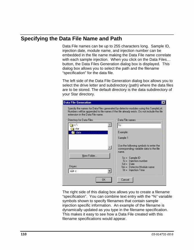
110 03-914731-00:6
Specifying the Data File Name and Path Data File names can be up to 255 characters long. Sample ID, injection date, module name, and injection number can be embedded in the file name making the Data File name correlate with each sample injection. When you click on the Data Files… button, the Data Files Generation dialog box is displayed. This dialog box allows you to select the path and the filename “specification” for the data file.
The left side of the Data File Generation dialog box allows you to select the drive letter and subdirectory (path) where the data files are to be stored. The default directory is the data subdirectory of your Star directory.
The right side of this dialog box allows you to create a filename “specification”. You can combine text entry with the “%” variable symbols shown to specify filenames that contain sample injection specific information. An example of the filename is dynamically updated as you type in the filename specification. This makes it easy to see how a Data File created with this filename specifications would appear.
INJECTING MULTIPLE SAMPLES Specifying Per-Sample Data Handling Parameters
Data Acquisition with 3800 GC Control 111
Specifying Per-Sample Data Handling Parameters Most Data Handling parameters are specified in the Method used during the injection. Some parameters may vary on a per-sample basis, and are therefore specified when you perform the injection. The following Data Handling parameters can be specified on a per-sample basis:
Unidentified Peak Factor
Multiplier
Divisor
Amount Standard when one Internal Standard is being used
Refer to the Data Handling and Reports Operation Manual for a brief description of these parameters.
Refer to the Regulatory Compliance Manual for a complete description of how these parameters are used to calculate results.
Not only can you specify these parameters on a per-sample basis, but you can specify them on a per-detector channel basis. This is useful if, for example, you have more than one detector installed on your 3800 GC. In addition, if you are using multiple internal standards, you can also specify their amounts on a per sample and per detector channel basis.
To access these extended Data Handling parameters, click on the button in the MultiChannel MultiStandard column in the 8200 SampleList. The Data Handling Channels dialog box is displayed. When you select the detector channel in the Data Handling Channels dialog box, the calculation type, internal standard peaks and amounts are read from the active Method. Be sure the Method you will be using is already active before you enter detector-specific parameters.
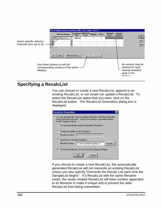
112 03-914731-00:6
Specifying a RecalcList You can choose to create a new RecalcList, append to an existing RecalcList, or not create nor update a RecalcList. To select the RecalcList option that you want, click on the RecalcList button. The RecalcList Generation dialog box is displayed.
If you choose to create a new RecalcList, this automatically generated RecalcList will not overwrite an existing RecalcList unless you also specify “Overwrite the Recalc List each time the SampleList begins”. If a RecalcList with the same filename exists, the newly created RecalcList will have number appended to its filename to make it unique and to prevent the older RecalcList from being overwritten.
Select specific detector channels here (up to 4).
Use these buttons to edit the corresponding sections of the active Method.
An amount may be entered for each internal standard peak in the Method
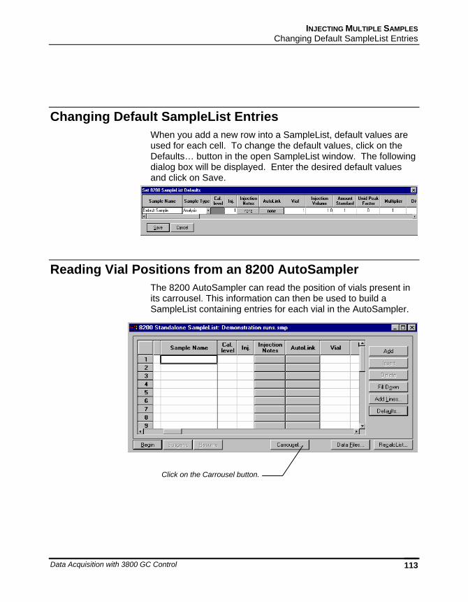
INJECTING MULTIPLE SAMPLES Changing Default SampleList Entries
Data Acquisition with 3800 GC Control 113
Changing Default SampleList Entries When you add a new row into a SampleList, default values are used for each cell. To change the default values, click on the Defaults… button in the open SampleList window. The following dialog box will be displayed. Enter the desired default values and click on Save.
Reading Vial Positions from an 8200 AutoSampler The 8200 AutoSampler can read the position of vials present in its carrousel. This information can then be used to build a SampleList containing entries for each vial in the AutoSampler.
Click on the Carrousel button.
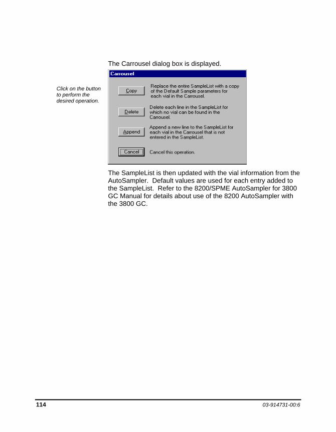
114 03-914731-00:6
The Carrousel dialog box is displayed.
The SampleList is then updated with the vial information from the AutoSampler. Default values are used for each entry added to the SampleList. Refer to the 8200/SPME AutoSampler for 3800 GC Manual for details about use of the 8200 AutoSampler with the 3800 GC.
Click on the button to perform the desired operation.
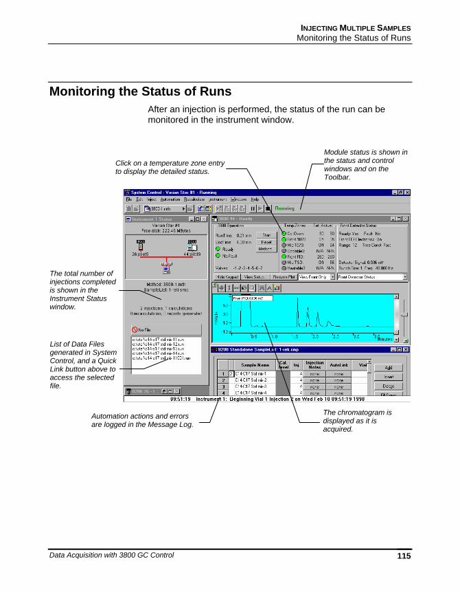
INJECTING MULTIPLE SAMPLES Monitoring the Status of Runs
Data Acquisition with 3800 GC Control 115
Monitoring the Status of Runs After an injection is performed, the status of the run can be monitored in the instrument window.
-
The total number of injections completed is shown in the Instrument Status window.
The chromatogram is displayed as it is acquired.
Automation actions and errors are logged in the Message Log.
List of Data Files generated in System Control, and a Quick Link button above to access the selected file.
Click on a temperature zone entry to display the detailed status.
Module status is shown in the status and control windows and on the Toolbar.
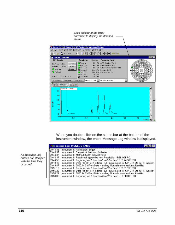
116 03-914731-00:6
When you double-click on the status bar at the bottom of the instrument window, the entire Message Log window is displayed.
All Message Log entries are stamped with the time they occurred.
Click outside of the 8400 carrousel to display the detailed status.
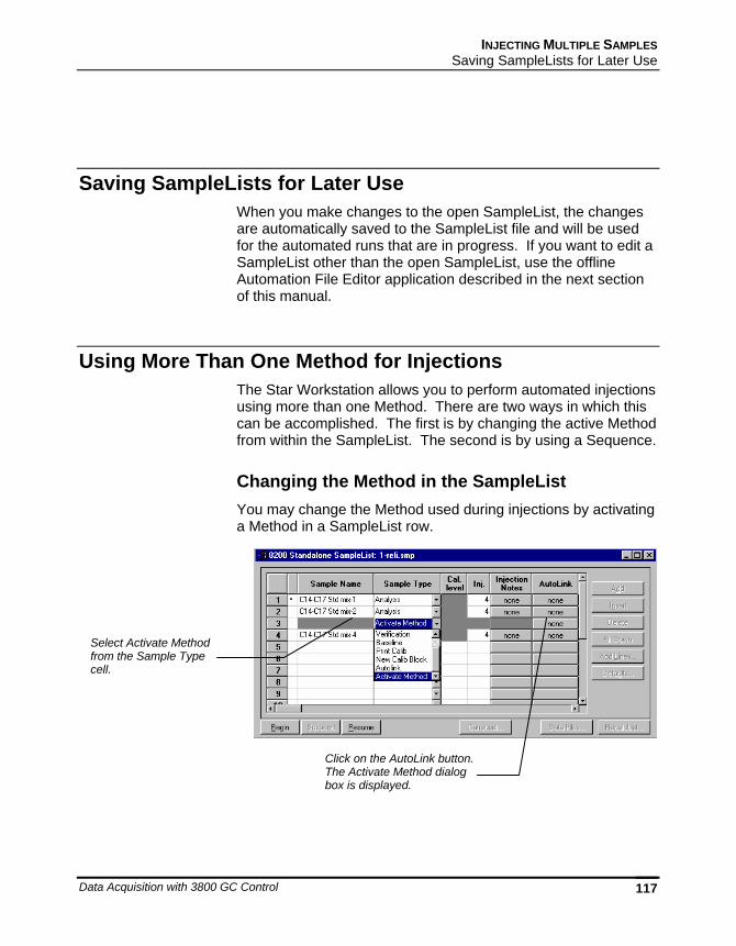
INJECTING MULTIPLE SAMPLES Saving SampleLists for Later Use
Data Acquisition with 3800 GC Control 117
Saving SampleLists for Later Use When you make changes to the open SampleList, the changes are automatically saved to the SampleList file and will be used for the automated runs that are in progress. If you want to edit a SampleList other than the open SampleList, use the offline Automation File Editor application described in the next section of this manual.
Using More Than One Method for Injections The Star Workstation allows you to perform automated injections using more than one Method. There are two ways in which this can be accomplished. The first is by changing the active Method from within the SampleList. The second is by using a Sequence.
Changing the Method in the SampleList You may change the Method used during injections by activating a Method in a SampleList row.
Select Activate Method from the Sample Type cell.
Click on the AutoLink button. The Activate Method dialog box is displayed.
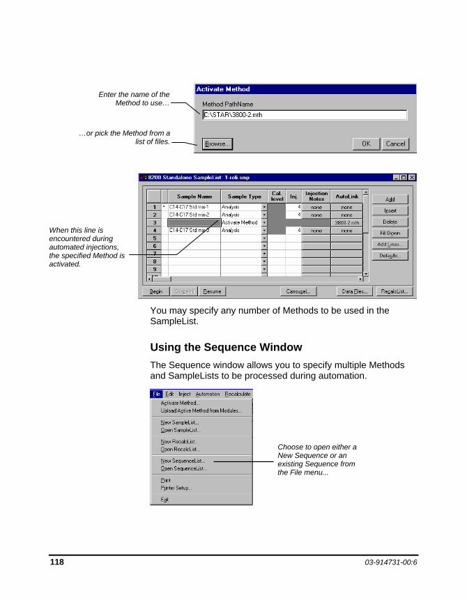
118 03-914731-00:6
You may specify any number of Methods to be used in the SampleList.
Using the Sequence Window The Sequence window allows you to specify multiple Methods and SampleLists to be processed during automation.
Enter the name of the Method to use…
…or pick the Method from a list of files.
When this line is encountered during automated injections, the specified Method is activated.
Choose to open either a New Sequence or an existing Sequence from the File menu...
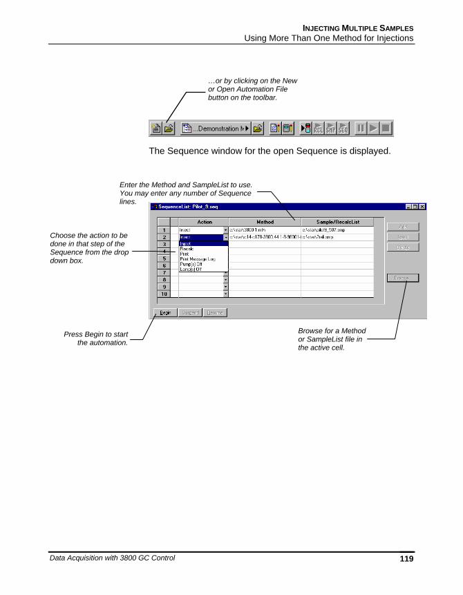
INJECTING MULTIPLE SAMPLES Using More Than One Method for Injections
Data Acquisition with 3800 GC Control 119
The Sequence window for the open Sequence is displayed.
Enter the Method and SampleList to use. You may enter any number of Sequence lines.
Choose the action to be done in that step of the Sequence from the drop down box.
Browse for a Method or SampleList file in the active cell.
Press Begin to start the automation.
…or by clicking on the New or Open Automation File button on the toolbar.

120 03-914731-00:6
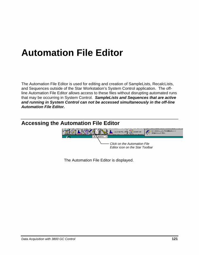
Data Acquisition with 3800 GC Control 121
Automation File Editor
The Automation File Editor is used for editing and creation of SampleLists, RecalcLists, and Sequences outside of the Star Workstation’s System Control application. The off-line Automation File Editor allows access to these files without disrupting automated runs that may be occurring in System Control. SampleLists and Sequences that are active and running in System Control can not be accessed simultaneously in the off-line Automation File Editor.
Accessing the Automation File Editor
The Automation File Editor is displayed.
Click on the Automation File Editor icon on the Star Toolbar
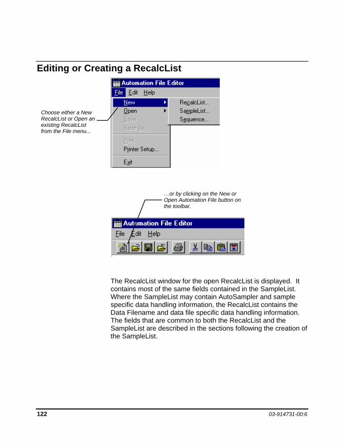
122 03-914731-00:6
Editing or Creating a RecalcList
The RecalcList window for the open RecalcList is displayed. It contains most of the same fields contained in the SampleList. Where the SampleList may contain AutoSampler and sample specific data handling information, the RecalcList contains the Data Filename and data file specific data handling information. The fields that are common to both the RecalcList and the SampleList are described in the sections following the creation of the SampleList.
Choose either a New RecalcList or Open an existing RecalcList from the File menu...
…or by clicking on the New or Open Automation File button on the toolbar.
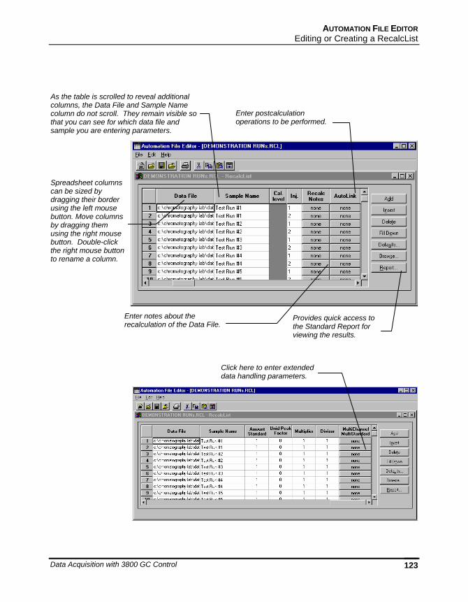
AUTOMATION FILE EDITOR Editing or Creating a RecalcList
Data Acquisition with 3800 GC Control 123
Spreadsheet columns can be sized by dragging their border using the left mouse button. Move columns by dragging them using the right mouse button. Double-click the right mouse button to rename a column.
Enter notes about the recalculation of the Data File.
Click here to enter extended data handling parameters.
Enter postcalculation operations to be performed.
Provides quick access to the Standard Report for viewing the results.
As the table is scrolled to reveal additional columns, the Data File and Sample Name column do not scroll. They remain visible so that you can see for which data file and sample you are entering parameters.
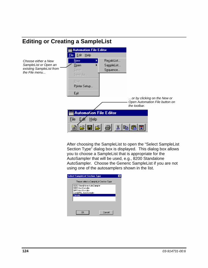
124 03-914731-00:6
Editing or Creating a SampleList
After choosing the SampleList to open the “Select SampleList Section Type” dialog box is displayed. This dialog box allows you to choose a SampleList that is appropriate for the AutoSampler that will be used, e.g., 8200 Standalone AutoSampler. Choose the Generic SampleList if you are not using one of the autosamplers shown in the list.
Choose either a New SampleList or Open an existing SampleList from the File menu...
…or by clicking on the New or Open Automation File button on the toolbar.
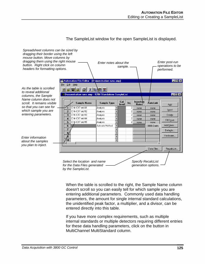
AUTOMATION FILE EDITOR Editing or Creating a SampleList
Data Acquisition with 3800 GC Control 125
The SampleList window for the open SampleList is displayed.
When the table is scrolled to the right, the Sample Name column doesn't scroll so you can easily tell for which sample you are entering additional parameters. Commonly used data handling parameters, the amount for single internal standard calculations, the unidentified peak factor, a multiplier, and a divisor, can be entered directly into this table.
If you have more complex requirements, such as multiple internal standards or multiple detectors requiring different entries for these data handling parameters, click on the button in MultiChannel MultiStandard column.
Enter information about the samples you plan to inject.
Select the location and name for the Data Files generated by the SampleList.
Enter notes about the sample.
Spreadsheet columns can be sized by dragging their border using the left mouse button. Move columns by dragging them using the right mouse button. Right click on column headers for formatting options.
Enter post-run operations to be performed.
As the table is scrolled to reveal additional columns, the Sample Name column does not scroll. It remains visible so that you can see for which sample you are entering parameters.
Specify RecalcList generation options.
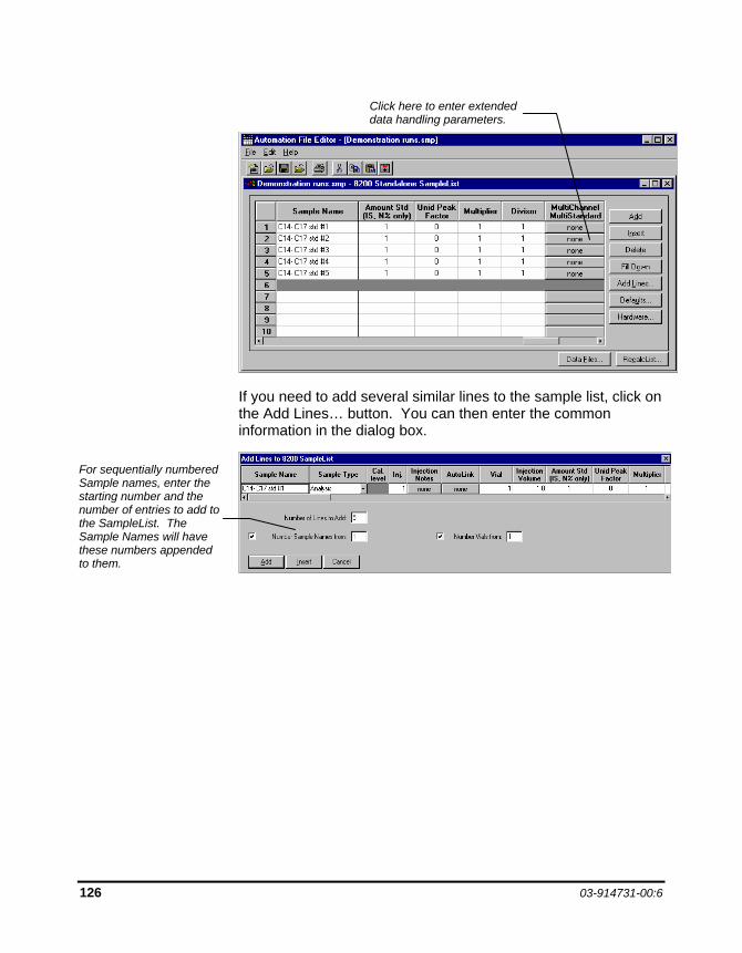
126 03-914731-00:6
If you need to add several similar lines to the sample list, click on the Add Lines… button. You can then enter the common information in the dialog box.
For sequentially numbered Sample names, enter the starting number and the number of entries to add to the SampleList. The Sample Names will have these numbers appended to them.
Click here to enter extended data handling parameters.
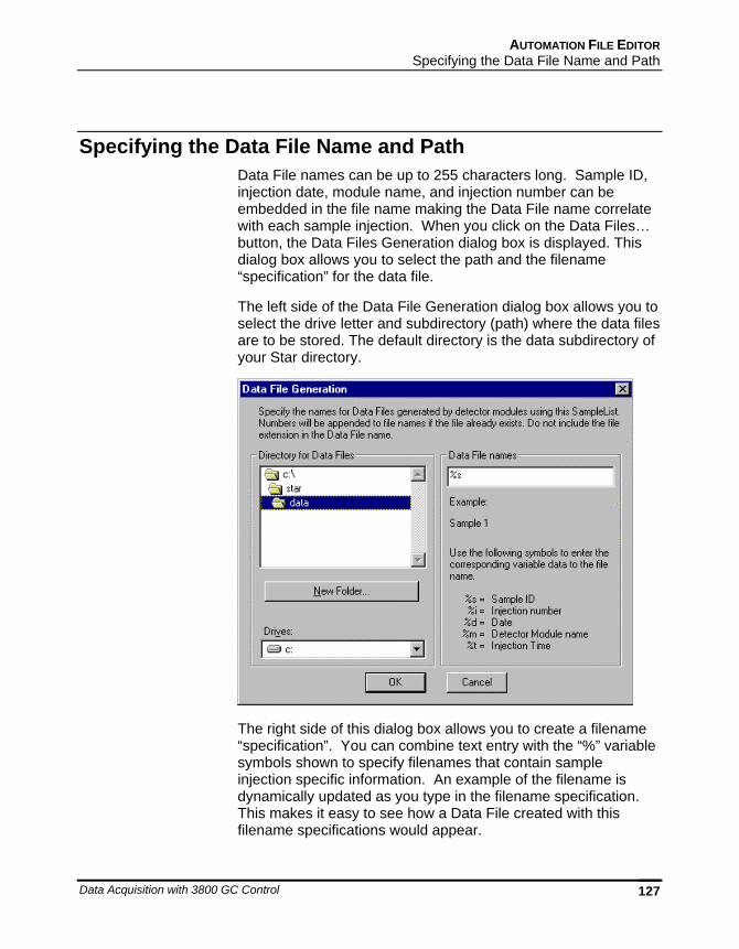
AUTOMATION FILE EDITOR Specifying the Data File Name and Path
Data Acquisition with 3800 GC Control 127
Specifying the Data File Name and Path Data File names can be up to 255 characters long. Sample ID, injection date, module name, and injection number can be embedded in the file name making the Data File name correlate with each sample injection. When you click on the Data Files… button, the Data Files Generation dialog box is displayed. This dialog box allows you to select the path and the filename “specification” for the data file.
The left side of the Data File Generation dialog box allows you to select the drive letter and subdirectory (path) where the data files are to be stored. The default directory is the data subdirectory of your Star directory.
The right side of this dialog box allows you to create a filename “specification”. You can combine text entry with the “%” variable symbols shown to specify filenames that contain sample injection specific information. An example of the filename is dynamically updated as you type in the filename specification. This makes it easy to see how a Data File created with this filename specifications would appear.
128 03-914731-00:6
Specifying Per-Sample Data Handling Parameters Most Data Handling parameters are specified in the Method used during the injection. Some parameters may vary on a per-sample basis, and are therefore specified when you perform the injection. The following Data Handling parameters can be specified on a per-sample basis:
Unidentified Peak Factor
Multiplier
Divisor
Amount Standard when one Internal Standard is being used
Refer to the Data Handling and Reports Operation Manual for a brief description of these parameters.
Refer to the Regulatory Compliance Manual for a complete description of how these parameters are used to calculate results.
Not only can you specify these parameters on a per-sample basis, but you can specify them on a per-detector channel basis. This is useful if, for example, you have different detectors installed on your 3800 GC. In addition, if you are using multiple internal standards, you can also specify their amounts on a per sample and per detector channel basis.
To access these extended Data Handling parameters, click on the button in the Multi-Channel Multi-Standard column in the 8200 SampleList. You will be prompted for the Method that will be used when this SampleList is run. Then Data Handling Channels dialog box is displayed. When you select the detector channel in the Data Handling Channels dialog box, the calculation type, internal standard peaks and amounts are read from the Method that you just selected. The values entered for internal standard peaks and amounts will be entered into the peak table of this method.
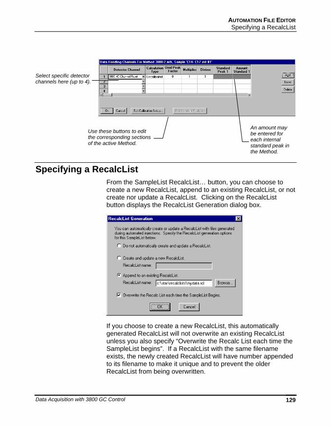
AUTOMATION FILE EDITOR Specifying a RecalcList
Data Acquisition with 3800 GC Control 129
Specifying a RecalcList From the SampleList RecalcList… button, you can choose to create a new RecalcList, append to an existing RecalcList, or not create nor update a RecalcList. Clicking on the RecalcList button displays the RecalcList Generation dialog box.
If you choose to create a new RecalcList, this automatically generated RecalcList will not overwrite an existing RecalcList unless you also specify “Overwrite the Recalc List each time the SampleList begins”. If a RecalcList with the same filename exists, the newly created RecalcList will have number appended to its filename to make it unique and to prevent the older RecalcList from being overwritten.
Select specific detector channels here (up to 4).
Use these buttons to edit the corresponding sections of the active Method.
An amount may be entered for each internal standard peak in the Method.
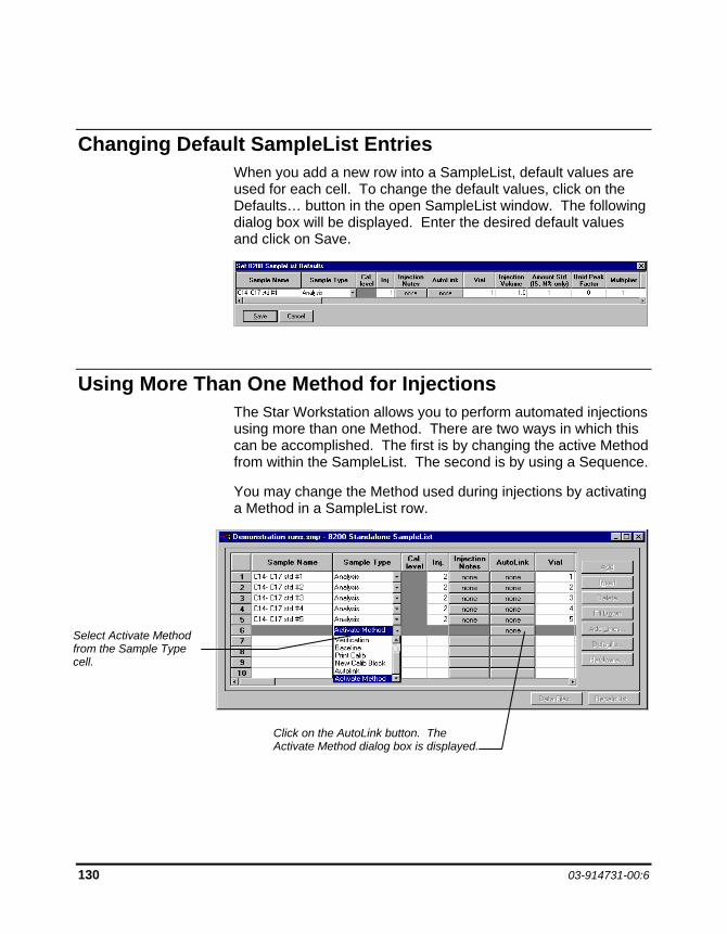
130 03-914731-00:6
Changing Default SampleList Entries When you add a new row into a SampleList, default values are used for each cell. To change the default values, click on the Defaults… button in the open SampleList window. The following dialog box will be displayed. Enter the desired default values and click on Save.
Using More Than One Method for Injections The Star Workstation allows you to perform automated injections using more than one Method. There are two ways in which this can be accomplished. The first is by changing the active Method from within the SampleList. The second is by using a Sequence.
You may change the Method used during injections by activating a Method in a SampleList row.
Select Activate Method from the Sample Type cell.
Click on the AutoLink button. The Activate Method dialog box is displayed.
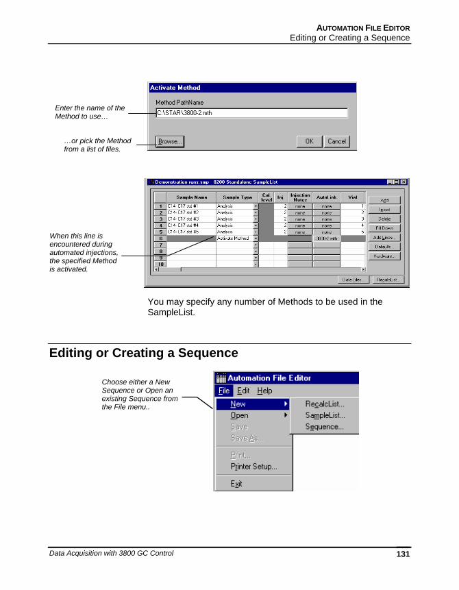
AUTOMATION FILE EDITOR Editing or Creating a Sequence
Data Acquisition with 3800 GC Control 131
You may specify any number of Methods to be used in the SampleList.
Editing or Creating a Sequence
Enter the name of the Method to use…
…or pick the Method from a list of files.
When this line is encountered during automated injections, the specified Method is activated.
Choose either a New Sequence or Open an existing Sequence from the File menu..
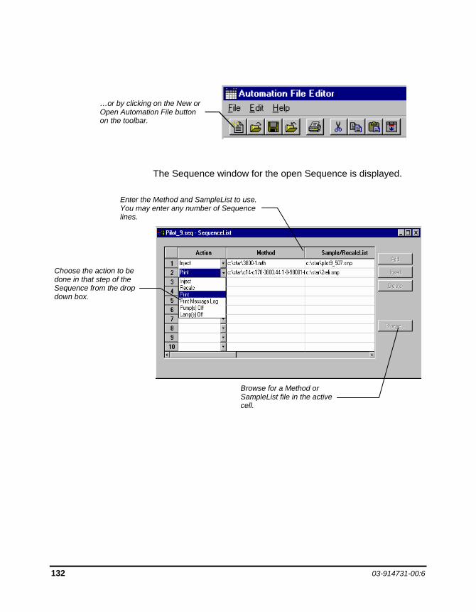
132 03-914731-00:6
The Sequence window for the open Sequence is displayed.
Enter the Method and SampleList to use. You may enter any number of Sequence lines.
Choose the action to be done in that step of the Sequence from the drop down box.
Browse for a Method or SampleList file in the active cell.
…or by clicking on the New or Open Automation File button on the toolbar.
Data Acquisition with 3800 GC Control 133
Using the Combi PAL AutoSampler
This section describes the configuration and use of the Combi PAL Autosampler with the Varian Workstation. Please refer to the Pre-Installation Instructions for information on firmware version compatibility with the Varian Workstation software.
The Combi PAL is the most flexible AutoSampler controlled by the Varian Workstation. The CPAL driver and firmware are basically identical for the LC and GC configurations, and are differentiated only by their accessories and the mounting components. The driver is aware of the equipment installed and required by a given method.
Configuring the CPAL AutoSampler 1. Connect the Combi PAL to Your Varian Workstation.
The Combi PAL AutoSampler communicates with the Varian Workstation computer using the 9-pin serial communications cable. This cable is included in the package that comes with the Combi PAL purchase.
The cable connects to the Serial 1 position on the back of the Combi PAL and the RS232 port position of the controlling Workstation computer.
There should also be a synchronization cable that is used to connect the Combi PAL Interface 1 position to the S.I.D.1 position in the 3800 GC.
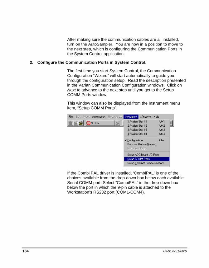
134 03-914731-00:6
After making sure the communication cables are all installed, turn on the AutoSampler. You are now in a position to move to the next step, which is configuring the Communication Ports in the System Control application.
2. Configure the Communication Ports in System Control.
The first time you start System Control, the Communication Configuration “Wizard” will start automatically to guide you through the configuration setup. Read the description presented in the Varian Communication Configuration windows. Click on Next to advance to the next step until you get to the Setup COMM Ports window.
This window can also be displayed from the Instrument menu item, “Setup COMM Ports”.
If the Combi PAL driver is installed, ‘CombiPAL’ is one of the choices available from the drop-down box below each available Serial COMM port. Select “CombiPAL” in the drop-down box below the port in which the 9-pin cable is attached to the Workstation’s RS232 port (COM1-COM4).
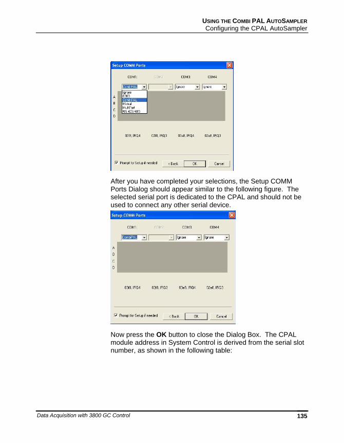
USING THE COMBI PAL AUTOSAMPLER Configuring the CPAL AutoSampler
Data Acquisition with 3800 GC Control 135
After you have completed your selections, the Setup COMM Ports Dialog should appear similar to the following figure. The selected serial port is dedicated to the CPAL and should not be used to connect any other serial device.
Now press the OK button to close the Dialog Box. The CPAL module address in System Control is derived from the serial slot number, as shown in the following table:
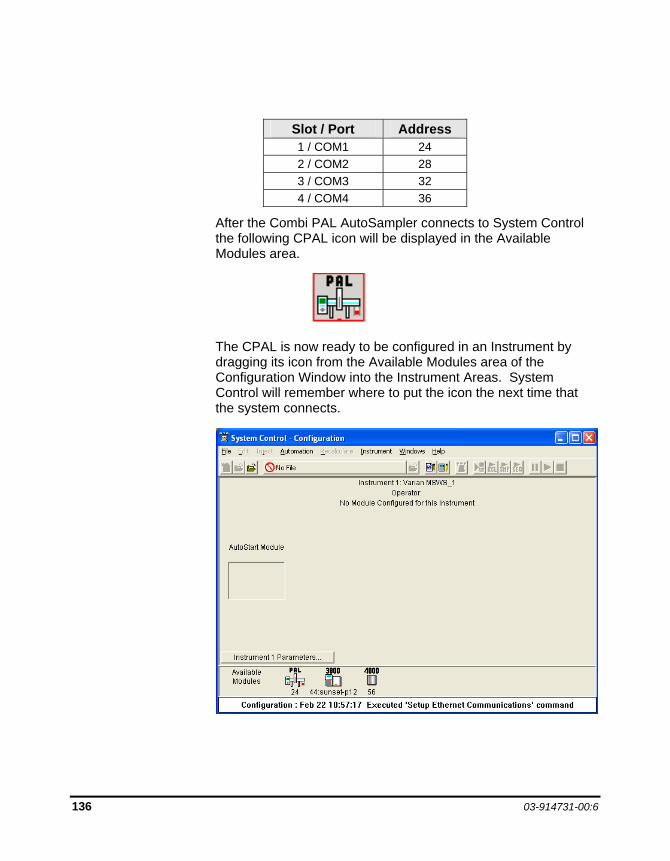
136 03-914731-00:6
Slot / Port Address 1 / COM1 24 2 / COM2 28 3 / COM3 32 4 / COM4 36
After the Combi PAL AutoSampler connects to System Control the following CPAL icon will be displayed in the Available Modules area.
The CPAL is now ready to be configured in an Instrument by dragging its icon from the Available Modules area of the Configuration Window into the Instrument Areas. System Control will remember where to put the icon the next time that the system connects.
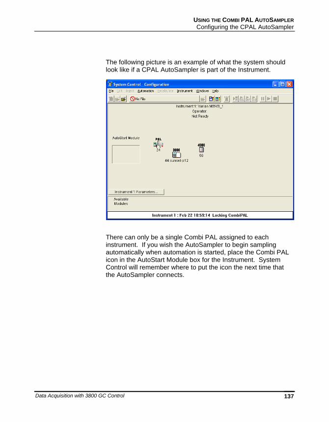
USING THE COMBI PAL AUTOSAMPLER Configuring the CPAL AutoSampler
Data Acquisition with 3800 GC Control 137
The following picture is an example of what the system should look like if a CPAL AutoSampler is part of the Instrument.
There can only be a single Combi PAL assigned to each instrument. If you wish the AutoSampler to begin sampling automatically when automation is started, place the Combi PAL icon in the AutoStart Module box for the Instrument. System Control will remember where to put the icon the next time that the AutoSampler connects.
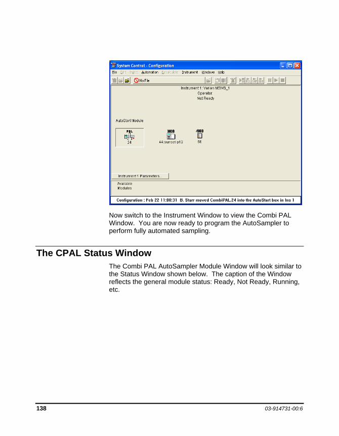
138 03-914731-00:6
Now switch to the Instrument Window to view the Combi PAL Window. You are now ready to program the AutoSampler to perform fully automated sampling.
The CPAL Status Window The Combi PAL AutoSampler Module Window will look similar to the Status Window shown below. The caption of the Window reflects the general module status: Ready, Not Ready, Running, etc.
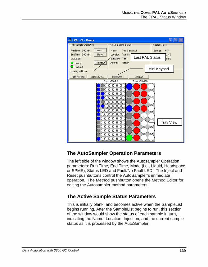
USING THE COMBI PAL AUTOSAMPLER The CPAL Status Window
Data Acquisition with 3800 GC Control 139
Last PAL Status
Mini Keypad
Tray View
The AutoSampler Operation Parameters The left side of the window shows the Autosampler Operation parameters: Run Time, End Time, Mode (i.e., Liquid, Headspace or SPME), Status LED and Fault/No Fault LED. The Inject and Reset pushbuttons control the AutoSampler’s immediate operation. The Method pushbutton opens the Method Editor for editing the Autosampler method parameters.
The Active Sample Status Parameters This is initially blank, and becomes active when the SampleList begins running. After the SampleList begins to run, this section of the window would show the status of each sample in turn, indicating the Name, Location, Injection, and the current sample status as it is processed by the AutoSampler.
140 03-914731-00:6
Heaters Status This group of parameters shows the status of the Syringe, Agitator and Bakeout (Heater Status). If any of these options were not relevant to the particular mode of your CPAL AutoSampler, then it would display N/A for Not Applicable.
Last CPAL Status This field contains the last meaningful status received from the Combi PAL firmware.
Mini-Keypad Buttons The following buttons are located between the AutoSampler Status Window and the sample Tray View window:
The Hide keypad button allows you to conceal the upper part “keypad” of the Status window and gain a larger view of the sample tray or plate layout.
The Unlock CPAL button allows you to release control of the AutoSampler, in order to re-establish manual control, e.g. to change syringes. When the PAL is unlocked, the button becomes ‘Lock CPAL’ and the Combi PAL state is set to ‘Not Responding / Offline’.
The ‘Lock CPAL’ button, would regain control from the Star WS.
The Hardware button displays the detected Combi PAL AutoSampler hardware dialog, and would allow you to set standby values for heated zones if installed. Trays, Injector, Barcode, Agitator and Syringe would all indicate whether or not they are installed and if so, what type, name and position.
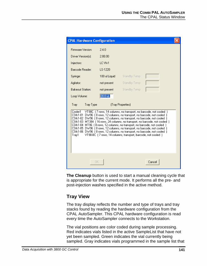
USING THE COMBI PAL AUTOSAMPLER The CPAL Status Window
Data Acquisition with 3800 GC Control 141
The Cleanup button is used to start a manual cleaning cycle that is appropriate for the current mode. It performs all the pre- and post-injection washes specified in the active method.
Tray View The tray display reflects the number and type of trays and tray stacks found by reading the hardware configuration from the CPAL AutoSampler. This CPAL hardware configuration is read every time the AutoSampler connects to the Workstation.
The vial positions are color coded during sample processing. Red indicates vials listed in the active SampleList that have not yet been sampled. Green indicates the vial currently being sampled. Gray indicates vials programmed in the sample list that
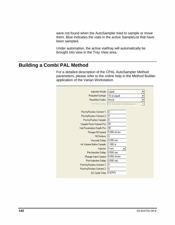
142 03-914731-00:6
were not found when the AutoSampler tried to sample or move them. Blue indicates the vials in the active SampleList that have been sampled.
Under automation, the active vial/tray will automatically be brought into view in the Tray View area.
Building a Combi PAL Method For a detailed description of the CPAL AutoSampler Method parameters, please refer to the online help in the Method Builder application of the Varian Workstation.
USING THE COMBI PAL AUTOSAMPLER Building a Combi PAL Method
Data Acquisition with 3800 GC Control 143
Modes of Operation There are 4 modes of operation available in the current version of the CPAL driver: GC Liquid, GC Headspace, GC SPME and LC mode.
All modes of operation support the use of a barcode reader. The bar codes must be placed vertically on the sample vials. When the Read Bar Codes is enabled in the CPAL Method, the sample vial is transported to the reader for the code to be scanned. The transport mechanism uses magnets to transport vials with magnetic vial caps. Different magnet sizes are used for 2 mL and 10/20 mL vials and therefore these two types cannot be mixed if barcodes are to be read.
All modes of operation support the preparation of the next sample (if any) during the current analysis (Prep Ahead). A Cycle Time parameter is provided to allow the preparation to start at the appropriate time.
GC Liquid Mode This mode uses relatively small syringes (1 - 100 µL) to Inject liquid sampled from tray vials into a GC Injector. The needle is cleaned via solvent flushes. This mode does not make use of the heated agitator accessory.
GC Headspace Mode This mode is used for the Injection of vapor sampled above a liquid into a GC Injector. This mode uses relatively large volumes (up to 5 mL). The headspace syringes are typically heated to prevent condensation.
The sampling is either performed in the Tray (ambient temp) or in an agitator accessory, which can optionally be heated. When the agitator is used, vials are transported to the agitator and equilibrated before sampling, then returned to their original position after injection or if any error is encountered. The needle is cleaned via a gas flushing built into the heated syringe.
144 03-914731-00:6
GC SPME Mode This mode uses a Solid Phase Micro Extraction Fiber, which is dipped in a liquid sample or held in the vapor above the liquid (Headspace SPME). This extracts some of the components of the sample, which can then be desorbed by heat in the injector or in the bakeout station.
The sampling can be performed in the Tray (ambient temp) or in an agitator accessory, which can optionally be heated. When the agitator is used, vials are transported to the agitator and equilibrated before sampling, then returned to their original position after injection or if any error is encountered.
The optional bakeout station provides a mechanism for cleaning the SPME fiber after injection.
LC Mode In this mode the CPAL samples a liquid from a tray vial and injects it in an HPLC Injection port. It is very similar to the GC Liquid mode, with the added provision of washing the injection port with one or two solvents after the injection.
LC Accessories include cooled trays, which have standalone temperature controller. The CPAL does not control or read-back the temperature for the cooled trays or tray stacks.

USING THE COMBI PAL AUTOSAMPLER Building CPAL SampleList
Data Acquisition with 3800 GC Control 145
Building CPAL SampleList Whenever you configure a Combi PAL AutoSampler Module in an Instrument as described above, the Instrument's SampleList is automatically reconfigured to the appropriate format for control of the CPAL including the specific hardware configuration. To create a SampleList in System Control, select the File New SampleList… Menu Command.
The ‘Create a New System Control SampleList File’ dialog is displayed and you are prompted to enter a File Name. Type a Name for your SampleList, select a “Save in:” directory and click on the Save button.
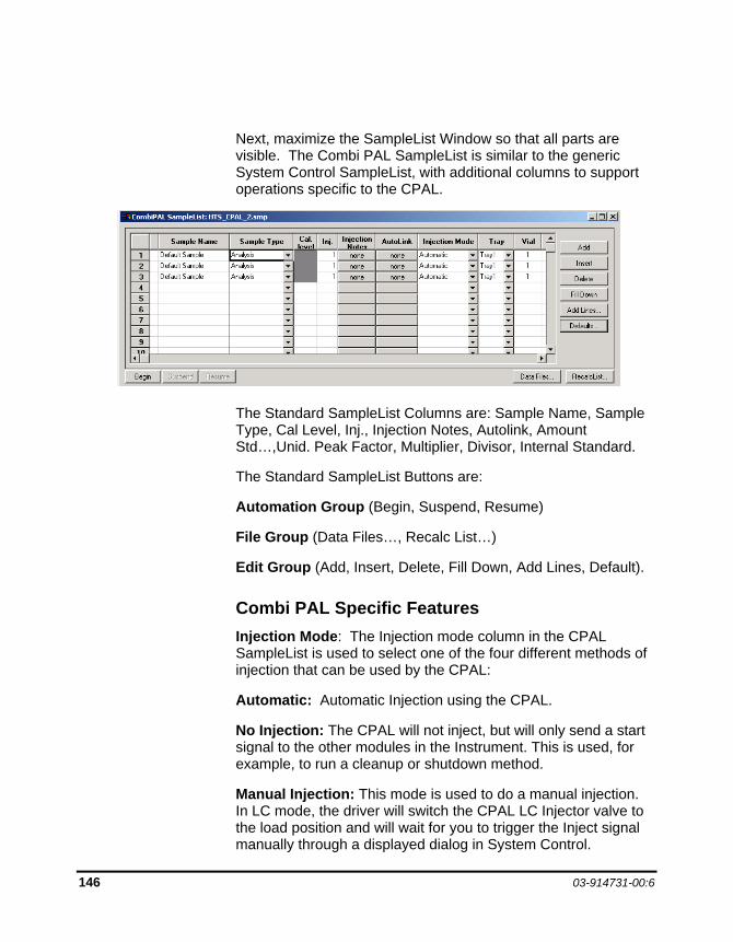
146 03-914731-00:6
Next, maximize the SampleList Window so that all parts are visible. The Combi PAL SampleList is similar to the generic System Control SampleList, with additional columns to support operations specific to the CPAL.
The Standard SampleList Columns are: Sample Name, Sample Type, Cal Level, Inj., Injection Notes, Autolink, Amount Std…,Unid. Peak Factor, Multiplier, Divisor, Internal Standard.
The Standard SampleList Buttons are:
Automation Group (Begin, Suspend, Resume)
File Group (Data Files…, Recalc List…)
Edit Group (Add, Insert, Delete, Fill Down, Add Lines, Default).
Combi PAL Specific Features Injection Mode: The Injection mode column in the CPAL SampleList is used to select one of the four different methods of injection that can be used by the CPAL:
Automatic: Automatic Injection using the CPAL.
No Injection: The CPAL will not inject, but will only send a start signal to the other modules in the Instrument. This is used, for example, to run a cleanup or shutdown method.
Manual Injection: This mode is used to do a manual injection. In LC mode, the driver will switch the CPAL LC Injector valve to the load position and will wait for you to trigger the Inject signal manually through a displayed dialog in System Control.
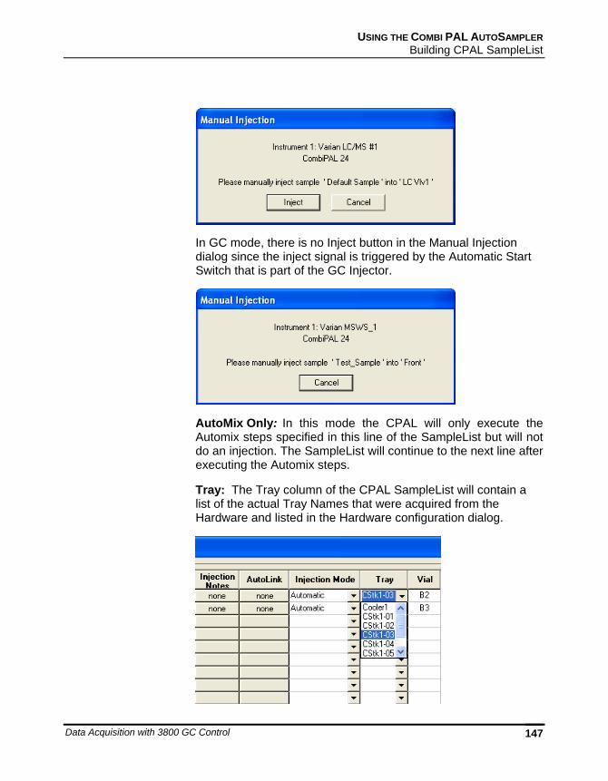
USING THE COMBI PAL AUTOSAMPLER Building CPAL SampleList
Data Acquisition with 3800 GC Control 147
In GC mode, there is no Inject button in the Manual Injection dialog since the inject signal is triggered by the Automatic Start Switch that is part of the GC Injector.
AutoMix Only: In this mode the CPAL will only execute the Automix steps specified in this line of the SampleList but will not do an injection. The SampleList will continue to the next line after executing the Automix steps.
Tray: The Tray column of the CPAL SampleList will contain a list of the actual Tray Names that were acquired from the Hardware and listed in the Hardware configuration dialog.
148 03-914731-00:6
Vial: The Vial column will provide vial selection and range that is appropriate for the Tray that was selected for the same sample line. The CPAL Vial column specifies the well or vial from which you want to aspirate the sample for injection. For the titer plates, the location is specified as a combination of row letter and column number. The available rows and column numbers depend on the type of plate that is configured in the CPAL Hardware. For example, you can enter A1 through H12 for the 96 well plate and A1 through P24 for the 384 well plates. You can use the Well/Vial column to perform random access to any well or vial; for example you can periodically recalibrate using a single standard at a fixed location.
Automix Routines: The Automix Routines column allows you to define a specific automixing program to be performed before injecting the sample for the purpose of derivatization, tagging, dilution, etc.
When performing an Automix routine, you can program the CPAL AutoSampler to aspirate a specified amount of liquid from a Well, Vial, or a Reagent Vial, and then transfer that liquid to the sample Well or Vial from which an injection is to be made. You can mix the sample by aspirating and dispensing specified amounts of the mixture, and you can program the AutoSampler to wait for a specific period of time for a reaction to take place.
The Combi PAL Automix program is displayed as a list box with Commands formatted as meaningful sentences.
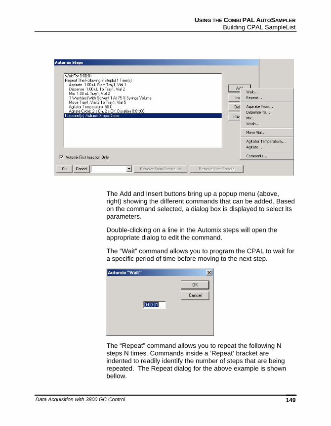
USING THE COMBI PAL AUTOSAMPLER Building CPAL SampleList
Data Acquisition with 3800 GC Control 149
The Add and Insert buttons bring up a popup menu (above, right) showing the different commands that can be added. Based on the command selected, a dialog box is displayed to select its parameters.
Double-clicking on a line in the Automix steps will open the appropriate dialog to edit the command.
The “Wait” command allows you to program the CPAL to wait for a specific period of time before moving to the next step.
The “Repeat” command allows you to repeat the following N steps N times. Commands inside a ‘Repeat’ bracket are indented to readily identify the number of steps that are being repeated. The Repeat dialog for the above example is shown bellow.
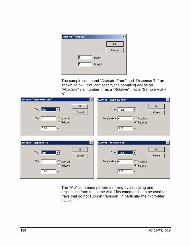
150 03-914731-00:6
The sample command “Aspirate From” and “Dispense To” are shown below. You can specify the sampling vial as an “Absolute” vial number or as a “Relative” that is “Sample Vial + N”.
The “Mix” command performs mixing by aspirating and dispensing from the same vial. This command is to be used for trays that do not support transport, in particular the micro-titer plates.
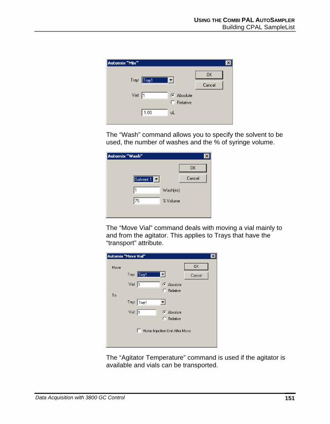
USING THE COMBI PAL AUTOSAMPLER Building CPAL SampleList
Data Acquisition with 3800 GC Control 151
The “Wash” command allows you to specify the solvent to be used, the number of washes and the % of syringe volume.
The “Move Vial” command deals with moving a vial mainly to and from the agitator. This applies to Trays that have the “transport” attribute.
The “Agitator Temperature” command is used if the agitator is available and vials can be transported.
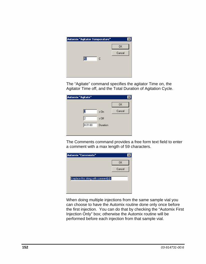
152 03-914731-00:6
The “Agitate” command specifies the agitator Time on, the Agitator Time off, and the Total Duration of Agitation Cycle.
The Comments command provides a free form text field to enter a comment with a max length of 59 characters.
When doing multiple injections from the same sample vial you can choose to have the Automix routine done only once before the first injection. You can do that by checking the “Automix First Injection Only” box; otherwise the Automix routine will be performed before each injection from that sample vial.
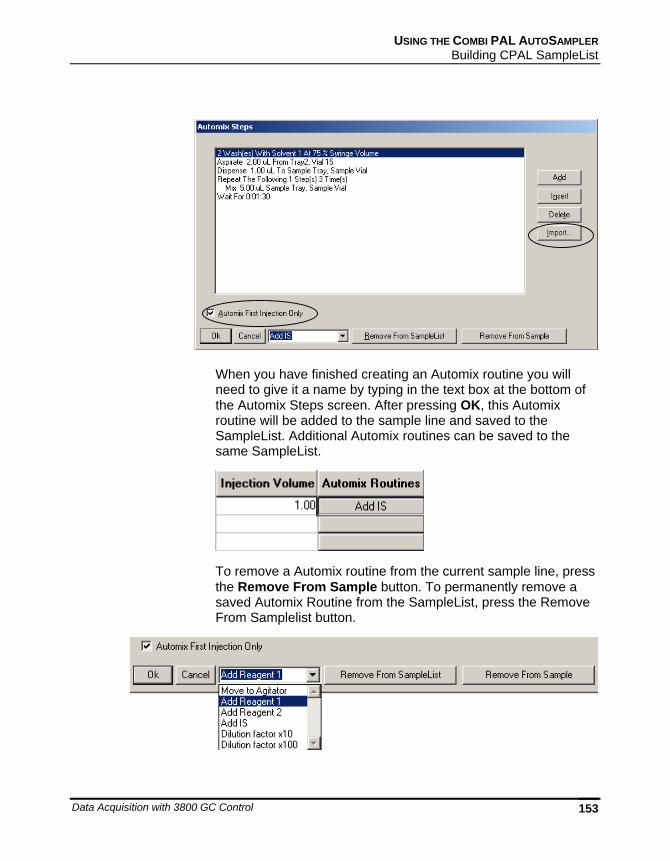
USING THE COMBI PAL AUTOSAMPLER Building CPAL SampleList
Data Acquisition with 3800 GC Control 153
When you have finished creating an Automix routine you will need to give it a name by typing in the text box at the bottom of the Automix Steps screen. After pressing OK, this Automix routine will be added to the sample line and saved to the SampleList. Additional Automix routines can be saved to the same SampleList.
To remove a Automix routine from the current sample line, press the Remove From Sample button. To permanently remove a saved Automix Routine from the SampleList, press the Remove From Samplelist button.
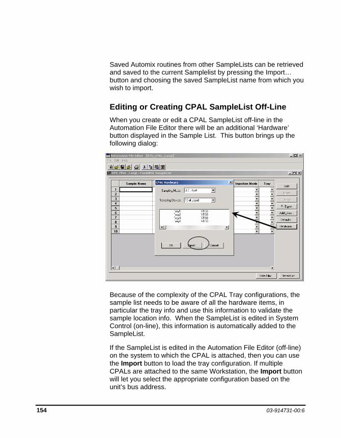
154 03-914731-00:6
Saved Automix routines from other SampleLists can be retrieved and saved to the current Samplelist by pressing the Import… button and choosing the saved SampleList name from which you wish to import.
Editing or Creating CPAL SampleList Off-Line When you create or edit a CPAL SampleList off-line in the Automation File Editor there will be an additional ‘Hardware’ button displayed in the Sample List. This button brings up the following dialog:
Because of the complexity of the CPAL Tray configurations, the sample list needs to be aware of all the hardware items, in particular the tray info and use this information to validate the sample location info. When the SampleList is edited in System Control (on-line), this information is automatically added to the SampleList.
If the SampleList is edited in the Automation File Editor (off-line) on the system to which the CPAL is attached, then you can use the Import button to load the tray configuration. If multiple CPALs are attached to the same Workstation, the Import button will let you select the appropriate configuration based on the unit’s bus address.
Data Acquisition with 3800 GC Control 155
CP-8400/CP-8410: Special Sampling Features
If your 3800 GC is equipped with a 2nd injector, the CP-8400 AutoSampler and the CP-8410 AutoInjector has the capability to inject into both injectors for a single chromatographic run.
You can program it to inject from a single vial into both injectors. The CP-8400 or CP-8410 will withdraw sample from a vial and inject into one injector then withdraw sample from the same vial and inject into the other injector. This allows you, for example, to analyze the same sample with two different detectors during the same chromatographic run. A single data file will be created with two channels of data, one for each detector. This particular capability is referred to as Duplicate injections.
You can also program it to inject from two adjacent vials, each into its own injector. The CP-8400/8410 will withdraw sample from a vial and inject into one injector then withdraw sample from the next vial position and inject it into the other injector. This allows you, for example, to analyze two similar samples with identical detectors during the same chromatographic run, thereby doubling your throughput. Two separate data files will be created with unique sample names, each with one channel of data. This particular capability is referred to as Dual Mode injections or Dual Sample injections.
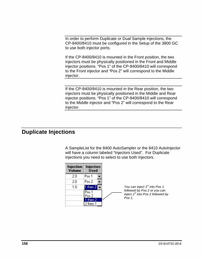
156 03-914731-00:6
In order to perform Duplicate or Dual Sample injections, the CP-8400/8410 must be configured in the Setup of the 3800 GC to use both injector ports. If the CP-8400/8410 is mounted in the Front position, the two injectors must be physically positioned in the Front and Middle injector positions. “Pos 1” of the CP-8400/8410 will correspond to the Front injector and “Pos 2” will correspond to the Middle injector.
If the CP-8400/8410 is mounted in the Rear position, the two injectors must be physically positioned in the Middle and Rear injector positions. “Pos 1” of the CP-8400/8410 will correspond to the Middle injector and “Pos 2” will correspond to the Rear injector.
Duplicate Injections
A SampleList for the 8400 AutoSampler or the 8410 AutoInjector will have a column labeled “Injectors Used”. For Duplicate injections you need to select to use both injectors.
You can inject 1st into Pos 1followed by Pos 2 or you caninject 1st into Pos 2 followed byPos 1.
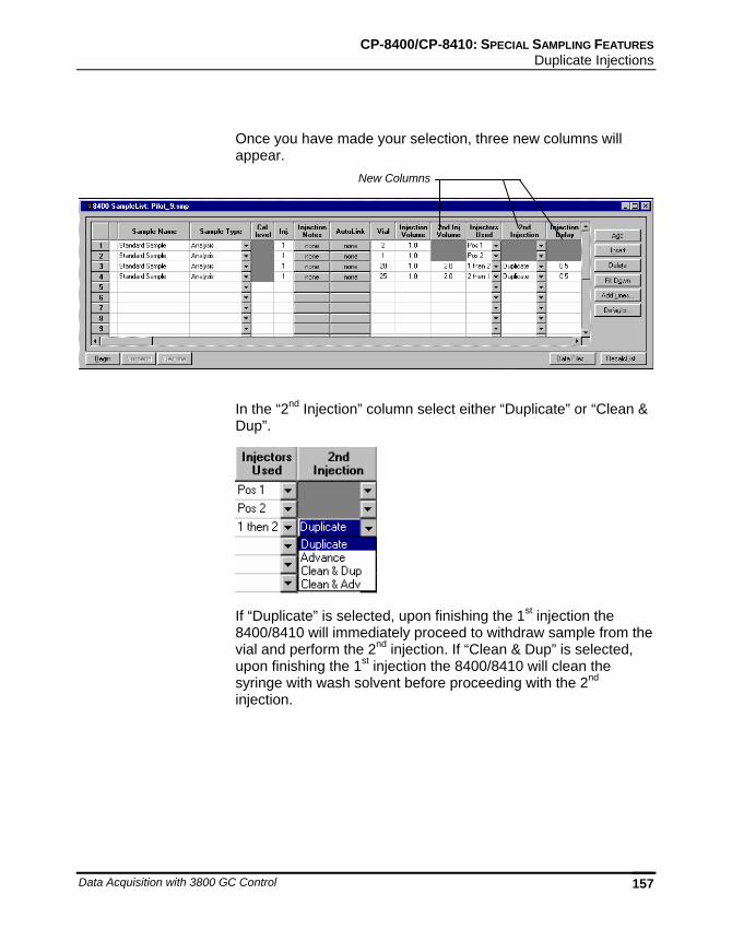
CP-8400/CP-8410: SPECIAL SAMPLING FEATURES Duplicate Injections
Data Acquisition with 3800 GC Control 157
Once you have made your selection, three new columns will appear.
In the “2nd Injection” column select either “Duplicate” or “Clean & Dup”.
If “Duplicate” is selected, upon finishing the 1st injection the 8400/8410 will immediately proceed to withdraw sample from the vial and perform the 2nd injection. If “Clean & Dup” is selected, upon finishing the 1st injection the 8400/8410 will clean the syringe with wash solvent before proceeding with the 2nd injection.
New Columns
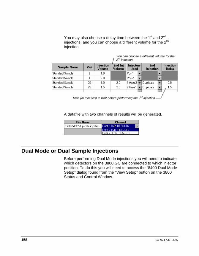
158 03-914731-00:6
You may also choose a delay time between the 1st and 2nd injections, and you can choose a different volume for the 2nd injection.
A datafile with two channels of results will be generated.
Dual Mode or Dual Sample Injections Before performing Dual Mode injections you will need to indicate which detectors on the 3800 GC are connected to which injector position. To do this you will need to access the “8400 Dual Mode Setup” dialog found from the “View Setup” button on the 3800 Status and Control Window.
Time (in minutes) to wait before performing the 2nd injection.
You can choose a different volume for the 2nd injection.
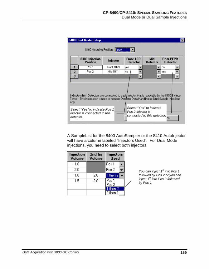
CP-8400/CP-8410: SPECIAL SAMPLING FEATURES Dual Mode or Dual Sample Injections
Data Acquisition with 3800 GC Control 159
Select “Yes” to indicate Pos 1injector is connected to thisdetector.
Select “Yes” to indicatePos 2 injector isconnected to this detector.
A SampleList for the 8400 AutoSampler or the 8410 AutoInjector will have a column labeled “Injectors Used”. For Dual Mode injections, you need to select both injectors.
You can inject 1st into Pos 1followed by Pos 2 or you caninject 1st into Pos 2 followedby Pos 1.

160 03-914731-00:6
Once you have made your selection, three new columns will appear.
In the “2nd Injection” column select either “Advance” or “Clean & Adv”.
If “Advance” is selected, upon finishing the 1st injection the 8400/8410 will immediately move to the next vial position and withdraw sample from the vial and perform the 2nd injection. If “Clean & Adv” is selected, upon finishing the 1st injection the 8400/8410 will advance to the next vial position and then clean the syringe with wash solvent before proceeding with the 2nd injection.
Once you have made your selection, an additional two new columns will appear.
New Columns
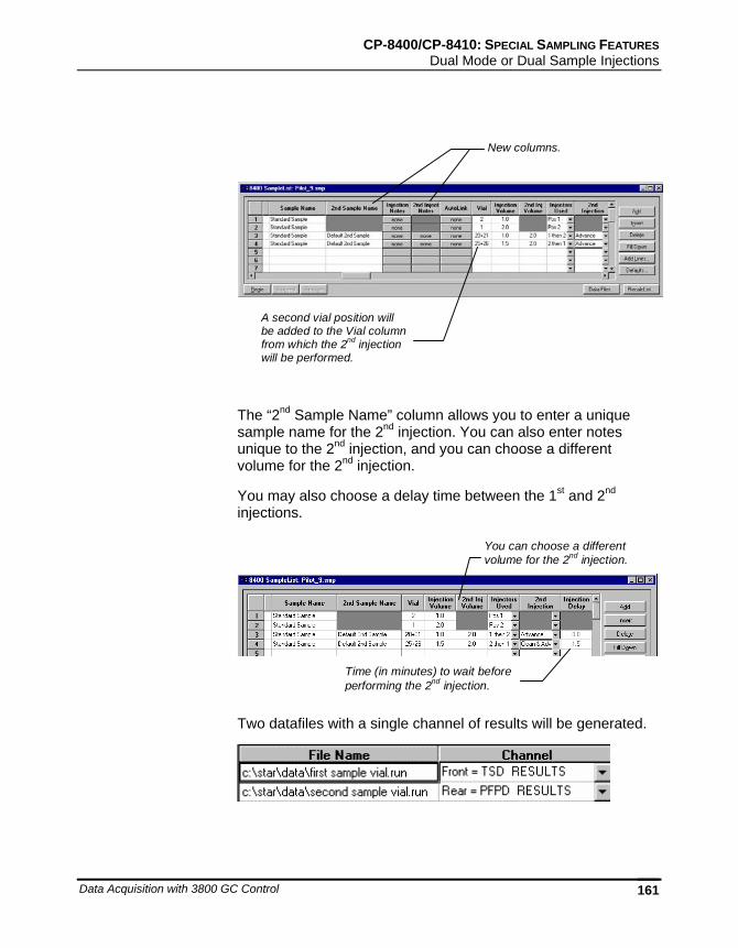
CP-8400/CP-8410: SPECIAL SAMPLING FEATURES Dual Mode or Dual Sample Injections
Data Acquisition with 3800 GC Control 161
New columns.
A second vial position willbe added to the Vial columnfrom which the 2nd injectionwill be performed.
The “2nd Sample Name” column allows you to enter a unique sample name for the 2nd injection. You can also enter notes unique to the 2nd injection, and you can choose a different volume for the 2nd injection.
You may also choose a delay time between the 1st and 2nd injections.
Time (in minutes) to wait beforeperforming the 2nd injection.
You can choose a differentvolume for the 2nd injection.
Two datafiles with a single channel of results will be generated.

162 03-914731-00:6
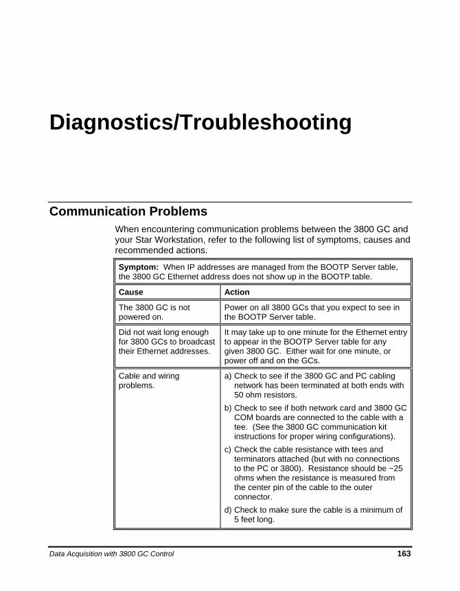
Data Acquisition with 3800 GC Control 163
Diagnostics/Troubleshooting
Communication Problems When encountering communication problems between the 3800 GC and your Star Workstation, refer to the following list of symptoms, causes and recommended actions.
Symptom: When IP addresses are managed from the BOOTP Server table, the 3800 GC Ethernet address does not show up in the BOOTP table.
Cause Action
The 3800 GC is not powered on.
Power on all 3800 GCs that you expect to see in the BOOTP Server table.
Did not wait long enough for 3800 GCs to broadcast their Ethernet addresses.
It may take up to one minute for the Ethernet entry to appear in the BOOTP Server table for any given 3800 GC. Either wait for one minute, or power off and on the GCs.
Cable and wiring problems.
a) Check to see if the 3800 GC and PC cabling network has been terminated at both ends with 50 ohm resistors.
b) Check to see if both network card and 3800 GC COM boards are connected to the cable with a tee. (See the 3800 GC communication kit instructions for proper wiring configurations).
c) Check the cable resistance with tees and terminators attached (but with no connections to the PC or 3800). Resistance should be ~25 ohms when the resistance is measured from the center pin of the cable to the outer connector.
d) Check to make sure the cable is a minimum of 5 feet long.
f
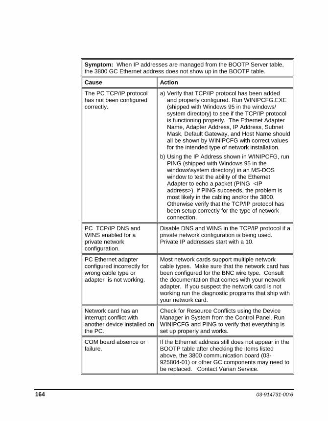
164 03-914731-00:6
Symptom: When IP addresses are managed from the BOOTP Server table, the 3800 GC Ethernet address does not show up in the BOOTP table.
Cause Action
The PC TCP/IP protocol has not been configured correctly.
a) Verify that TCP/IP protocol has been added and properly configured. Run WINIPCFG.EXE (shipped with Windows 95 in the windows/ system directory) to see if the TCP/IP protocol is functioning properly. The Ethernet Adapter Name, Adapter Address, IP Address, Subnet Mask, Default Gateway, and Host Name should all be shown by WINIPCFG with correct values for the intended type of network installation.
b) Using the IP Address shown in WINIPCFG, run PING (shipped with Windows 95 in the windows\system directory) in an MS-DOS window to test the ability of the Ethernet Adapter to echo a packet (PING <IP address>). If PING succeeds, the problem is most likely in the cabling and/or the 3800. Otherwise verify that the TCP/IP protocol has been setup correctly for the type of network connection.
PC TCP/IP DNS and WINS enabled for a private network configuration.
Disable DNS and WINS in the TCP/IP protocol if a private network configuration is being used. Private IP addresses start with a 10.
PC Ethernet adapter configured incorrectly for wrong cable type or adapter is not working.
Most network cards support multiple network cable types. Make sure that the network card has been configured for the BNC wire type. Consult the documentation that comes with your network adapter. If you suspect the network card is not working run the diagnostic programs that ship with your network card.
Network card has an interrupt conflict with another device installed on the PC.
Check for Resource Conflicts using the Device Manager in System from the Control Panel. Run WINIPCFG and PING to verify that everything is set up properly and works.
COM board absence or failure.
If the Ethernet address still does not appear in the BOOTP table after checking the items listed above, the 3800 communication board (03-925804-01) or other GC components may need to be replaced. Contact Varian Service.
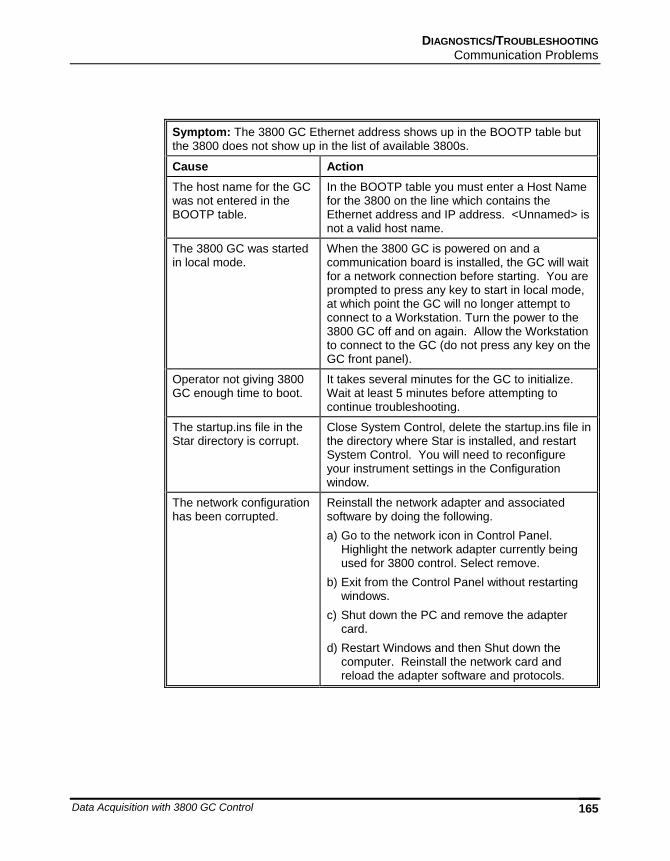
DIAGNOSTICS/TROUBLESHOOTING Communication Problems
Data Acquisition with 3800 GC Control 165
Symptom: The 3800 GC Ethernet address shows up in the BOOTP table but the 3800 does not show up in the list of available 3800s.
Cause Action The host name for the GC was not entered in the BOOTP table.
In the BOOTP table you must enter a Host Name for the 3800 on the line which contains the Ethernet address and IP address. <Unnamed> is not a valid host name.
The 3800 GC was started in local mode.
When the 3800 GC is powered on and a communication board is installed, the GC will wait for a network connection before starting. You are prompted to press any key to start in local mode, at which point the GC will no longer attempt to connect to a Workstation. Turn the power to the 3800 GC off and on again. Allow the Workstation to connect to the GC (do not press any key on the GC front panel).
Operator not giving 3800 GC enough time to boot.
It takes several minutes for the GC to initialize. Wait at least 5 minutes before attempting to continue troubleshooting.
The startup.ins file in the Star directory is corrupt.
Close System Control, delete the startup.ins file in the directory where Star is installed, and restart System Control. You will need to reconfigure your instrument settings in the Configuration window.
The network configuration has been corrupted.
Reinstall the network adapter and associated software by doing the following. a) Go to the network icon in Control Panel.
Highlight the network adapter currently being used for 3800 control. Select remove.
b) Exit from the Control Panel without restarting windows.
c) Shut down the PC and remove the adapter card.
d) Restart Windows and then Shut down the computer. Reinstall the network card and reload the adapter software and protocols.
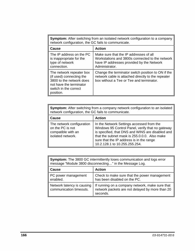
166 03-914731-00:6
Symptom: After switching from an isolated network configuration to a company network configuration, the GC fails to communicate. Cause Action The IP address on the PC is inappropriate for the type of network connection.
Make sure that the IP addresses of all Workstations and 3800s connected to the network have IP addresses provided by the Network Administrator.
The network repeater box (if used) connecting the 3800 to the network does not have the terminator switch in the correct position.
Change the terminator switch position to ON if the network cable is attached directly to the repeater box without a Tee or Tee and terminator.
Symptom: After switching from a company network configuration to an isolated network configuration, the GC fails to communicate. Cause Action The network configuration on the PC is not compatible with an isolated network.
In the Network Settings accessed from the Windows 95 Control Panel, verify that no gateway is specified, that DNS and WINS are disabled and that the subnet mask is 255.0.0.0. Also make sure that the IP address is in the range 10.2.128.1 to 10.255.255.254.
Symptom: The 3800 GC intermittently loses communication and logs error message “Module 3800 disconnecting…” in the Message Log. Cause Action PC power management enabled.
Check to make sure that the power management has been disabled on the PC.
Network latency is causing communication timeouts.
If running on a company network, make sure that network packets are not delayed by more than 20 seconds.
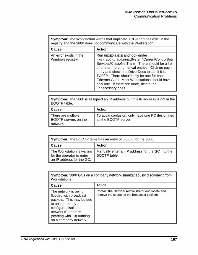
DIAGNOSTICS/TROUBLESHOOTING Communication Problems
Data Acquisition with 3800 GC Control 167
Symptom: The Workstation warns that duplicate TCP/IP entries exist in the registry and the 3800 does not communicate with the Workstation. Cause Action An error exists in the Windows registry.
Run REGEDIT.EXE and look under HKEY_LOCAL_MACHINE\System\CurrentControlSet\Services\Class\NetTrans. There should be a list of one or more numerical entries. Click on each entry and check the DriverDesc to see if it is TCP/IP. There should only be one for each Ethernet Card. Most Workstations should have only one. If there are more, delete the unnecessary ones.
Symptom: The 3800 is assigned an IP address but this IP address is not in the BOOTP table. Cause Action There are multiple BOOTP servers on the network.
To avoid confusion, only have one PC designated as the BOOTP server.
Symptom: The BOOTP table has an entry of 0.0.0.0 for the 3800. Cause Action The Workstation is waiting for the operator to enter an IP address for the GC.
Manually enter an IP address for the GC into the BOOTP table.
Symptom: 3800 GCs on a company network simultaneously disconnect from Workstations. Cause Action
The network is being flooded with broadcast packets. This may be due to an improperly configured isolated network IP address (starting with 10) running on a company network.
Contact the Network Administrator and locate and remove the source of the broadcast packets.
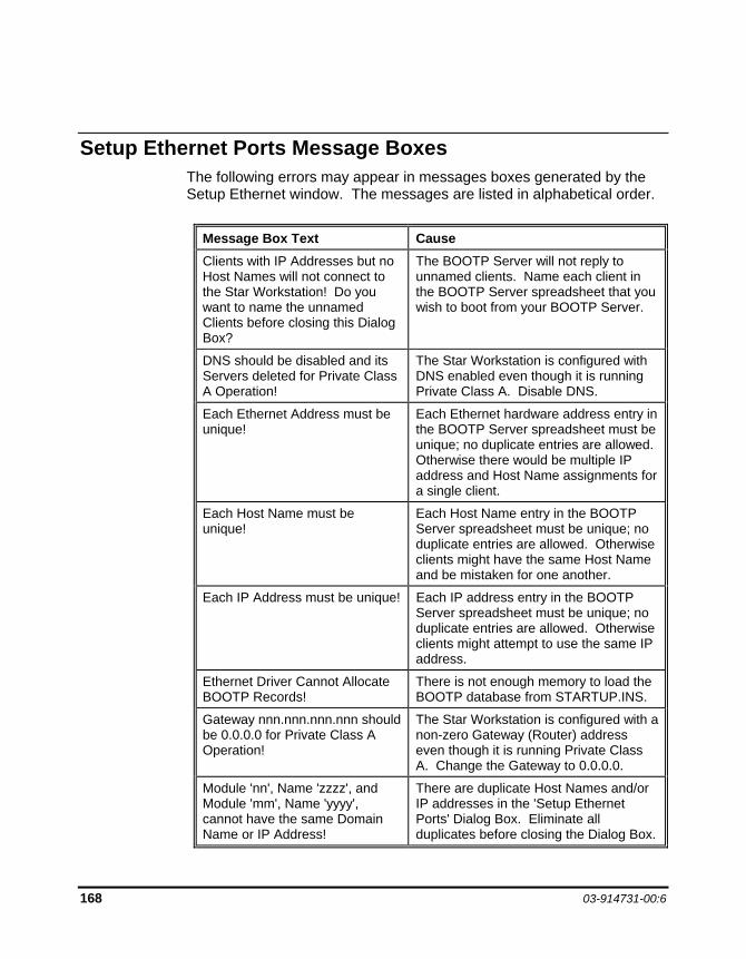
168 03-914731-00:6
Setup Ethernet Ports Message Boxes The following errors may appear in messages boxes generated by the Setup Ethernet window. The messages are listed in alphabetical order.
Message Box Text Cause Clients with IP Addresses but no Host Names will not connect to the Star Workstation! Do you want to name the unnamed Clients before closing this Dialog Box?
The BOOTP Server will not reply to unnamed clients. Name each client in the BOOTP Server spreadsheet that you wish to boot from your BOOTP Server.
DNS should be disabled and its Servers deleted for Private Class A Operation!
The Star Workstation is configured with DNS enabled even though it is running Private Class A. Disable DNS.
Each Ethernet Address must be unique!
Each Ethernet hardware address entry in the BOOTP Server spreadsheet must be unique; no duplicate entries are allowed. Otherwise there would be multiple IP address and Host Name assignments for a single client.
Each Host Name must be unique!
Each Host Name entry in the BOOTP Server spreadsheet must be unique; no duplicate entries are allowed. Otherwise clients might have the same Host Name and be mistaken for one another.
Each IP Address must be unique! Each IP address entry in the BOOTP Server spreadsheet must be unique; no duplicate entries are allowed. Otherwise clients might attempt to use the same IP address.
Ethernet Driver Cannot Allocate BOOTP Records!
There is not enough memory to load the BOOTP database from STARTUP.INS.
Gateway nnn.nnn.nnn.nnn should be 0.0.0.0 for Private Class A Operation!
The Star Workstation is configured with a non-zero Gateway (Router) address even though it is running Private Class A. Change the Gateway to 0.0.0.0.
Module 'nn', Name 'zzzz', and Module 'mm', Name 'yyyy', cannot have the same Domain Name or IP Address!
There are duplicate Host Names and/or IP addresses in the 'Setup Ethernet Ports' Dialog Box. Eliminate all duplicates before closing the Dialog Box.
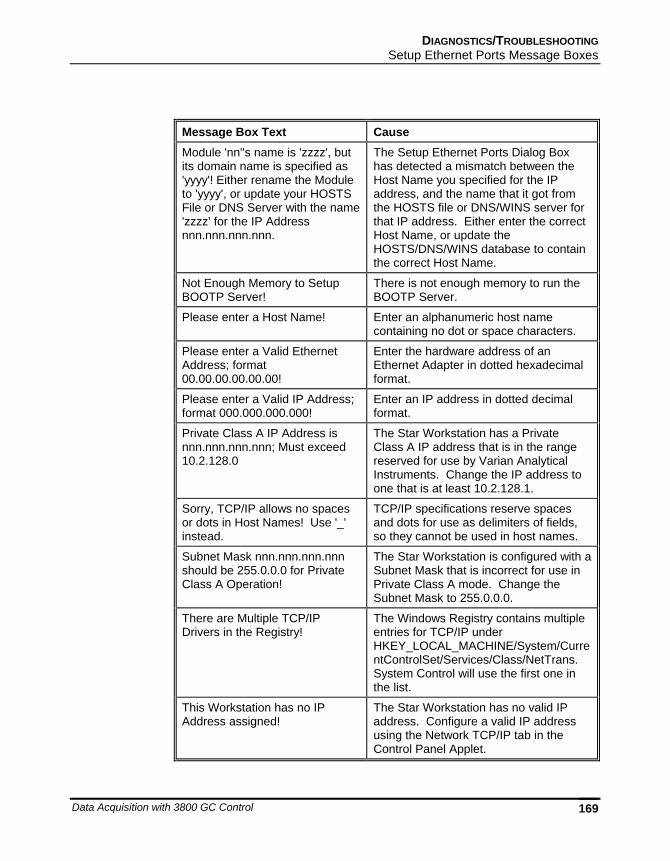
DIAGNOSTICS/TROUBLESHOOTING Setup Ethernet Ports Message Boxes
Data Acquisition with 3800 GC Control 169
Message Box Text Cause Module 'nn''s name is 'zzzz', but its domain name is specified as 'yyyy'! Either rename the Module to 'yyyy', or update your HOSTS File or DNS Server with the name 'zzzz' for the IP Address nnn.nnn.nnn.nnn.
The Setup Ethernet Ports Dialog Box has detected a mismatch between the Host Name you specified for the IP address, and the name that it got from the HOSTS file or DNS/WINS server for that IP address. Either enter the correct Host Name, or update the HOSTS/DNS/WINS database to contain the correct Host Name.
Not Enough Memory to Setup BOOTP Server!
There is not enough memory to run the BOOTP Server.
Please enter a Host Name! Enter an alphanumeric host name containing no dot or space characters.
Please enter a Valid Ethernet Address; format 00.00.00.00.00.00!
Enter the hardware address of an Ethernet Adapter in dotted hexadecimal format.
Please enter a Valid IP Address; format 000.000.000.000!
Enter an IP address in dotted decimal format.
Private Class A IP Address is nnn.nnn.nnn.nnn; Must exceed 10.2.128.0
The Star Workstation has a Private Class A IP address that is in the range reserved for use by Varian Analytical Instruments. Change the IP address to one that is at least 10.2.128.1.
Sorry, TCP/IP allows no spaces or dots in Host Names! Use '_' instead.
TCP/IP specifications reserve spaces and dots for use as delimiters of fields, so they cannot be used in host names.
Subnet Mask nnn.nnn.nnn.nnn should be 255.0.0.0 for Private Class A Operation!
The Star Workstation is configured with a Subnet Mask that is incorrect for use in Private Class A mode. Change the Subnet Mask to 255.0.0.0.
There are Multiple TCP/IP Drivers in the Registry!
The Windows Registry contains multiple entries for TCP/IP under HKEY_LOCAL_MACHINE/System/CurrentControlSet/Services/Class/NetTrans. System Control will use the first one in the list.
This Workstation has no IP Address assigned!
The Star Workstation has no valid IP address. Configure a valid IP address using the Network TCP/IP tab in the Control Panel Applet.
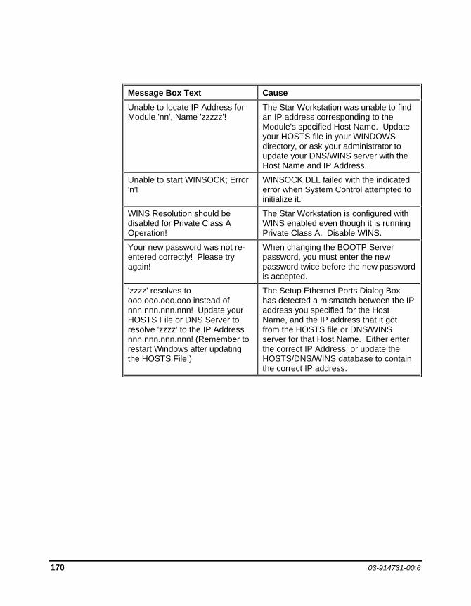
170 03-914731-00:6
Message Box Text Cause Unable to locate IP Address for Module 'nn', Name 'zzzzz'!
The Star Workstation was unable to find an IP address corresponding to the Module's specified Host Name. Update your HOSTS file in your WINDOWS directory, or ask your administrator to update your DNS/WINS server with the Host Name and IP Address.
Unable to start WINSOCK; Error 'n'!
WINSOCK.DLL failed with the indicated error when System Control attempted to initialize it.
WINS Resolution should be disabled for Private Class A Operation!
The Star Workstation is configured with WINS enabled even though it is running Private Class A. Disable WINS.
Your new password was not re-entered correctly! Please try again!
When changing the BOOTP Server password, you must enter the new password twice before the new password is accepted.
'zzzz' resolves to ooo.ooo.ooo.ooo instead of nnn.nnn.nnn.nnn! Update your HOSTS File or DNS Server to resolve 'zzzz' to the IP Address nnn.nnn.nnn.nnn! (Remember to restart Windows after updating the HOSTS File!)
The Setup Ethernet Ports Dialog Box has detected a mismatch between the IP address you specified for the Host Name, and the IP address that it got from the HOSTS file or DNS/WINS server for that Host Name. Either enter the correct IP Address, or update the HOSTS/DNS/WINS database to contain the correct IP address.
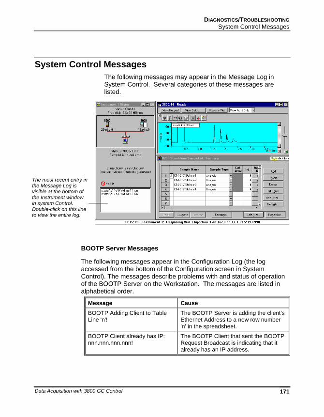
DIAGNOSTICS/TROUBLESHOOTING System Control Messages
Data Acquisition with 3800 GC Control 171
System Control Messages The following messages may appear in the Message Log in System Control. Several categories of these messages are listed.
BOOTP Server Messages
The following messages appear in the Configuration Log (the log accessed from the bottom of the Configuration screen in System Control). The messages describe problems with and status of operation of the BOOTP Server on the Workstation. The messages are listed in alphabetical order.
Message Cause BOOTP Adding Client to Table Line 'n'!
The BOOTP Server is adding the client's Ethernet Address to a new row number 'n' in the spreadsheet.
BOOTP Client already has IP: nnn.nnn.nnn.nnn!
The BOOTP Client that sent the BOOTP Request Broadcast is indicating that it already has an IP address.
The most recent entry in the Message Log is visible at the bottom of the Instrument window in system Control. Double-click on this line to view the entire log.
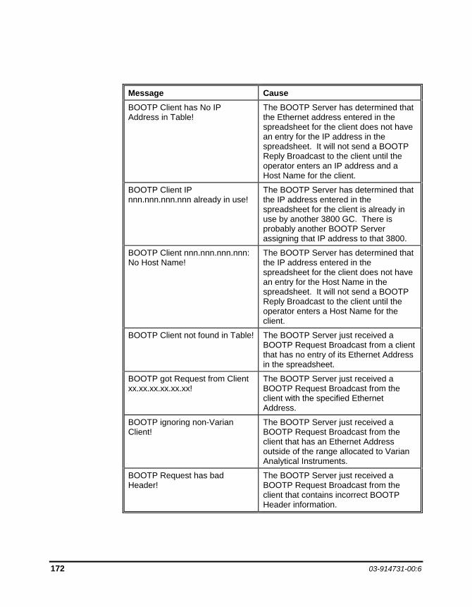
172 03-914731-00:6
Message Cause BOOTP Client has No IP Address in Table!
The BOOTP Server has determined that the Ethernet address entered in the spreadsheet for the client does not have an entry for the IP address in the spreadsheet. It will not send a BOOTP Reply Broadcast to the client until the operator enters an IP address and a Host Name for the client.
BOOTP Client IP nnn.nnn.nnn.nnn already in use!
The BOOTP Server has determined that the IP address entered in the spreadsheet for the client is already in use by another 3800 GC. There is probably another BOOTP Server assigning that IP address to that 3800.
BOOTP Client nnn.nnn.nnn.nnn: No Host Name!
The BOOTP Server has determined that the IP address entered in the spreadsheet for the client does not have an entry for the Host Name in the spreadsheet. It will not send a BOOTP Reply Broadcast to the client until the operator enters a Host Name for the client.
BOOTP Client not found in Table! The BOOTP Server just received a BOOTP Request Broadcast from a client that has no entry of its Ethernet Address in the spreadsheet.
BOOTP got Request from Client xx.xx.xx.xx.xx.xx!
The BOOTP Server just received a BOOTP Request Broadcast from the client with the specified Ethernet Address.
BOOTP ignoring non-Varian Client!
The BOOTP Server just received a BOOTP Request Broadcast from the client that has an Ethernet Address outside of the range allocated to Varian Analytical Instruments.
BOOTP Request has bad Header!
The BOOTP Server just received a BOOTP Request Broadcast from the client that contains incorrect BOOTP Header information.
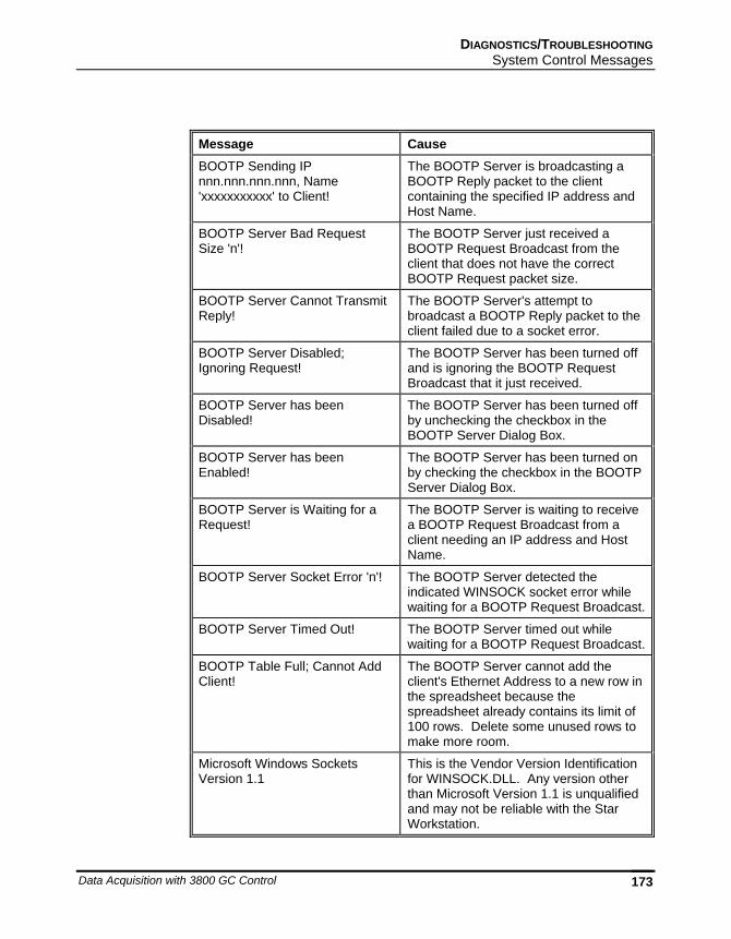
DIAGNOSTICS/TROUBLESHOOTING System Control Messages
Data Acquisition with 3800 GC Control 173
Message Cause BOOTP Sending IP nnn.nnn.nnn.nnn, Name 'xxxxxxxxxxx' to Client!
The BOOTP Server is broadcasting a BOOTP Reply packet to the client containing the specified IP address and Host Name.
BOOTP Server Bad Request Size 'n'!
The BOOTP Server just received a BOOTP Request Broadcast from the client that does not have the correct BOOTP Request packet size.
BOOTP Server Cannot Transmit Reply!
The BOOTP Server's attempt to broadcast a BOOTP Reply packet to the client failed due to a socket error.
BOOTP Server Disabled; Ignoring Request!
The BOOTP Server has been turned off and is ignoring the BOOTP Request Broadcast that it just received.
BOOTP Server has been Disabled!
The BOOTP Server has been turned off by unchecking the checkbox in the BOOTP Server Dialog Box.
BOOTP Server has been Enabled!
The BOOTP Server has been turned on by checking the checkbox in the BOOTP Server Dialog Box.
BOOTP Server is Waiting for a Request!
The BOOTP Server is waiting to receive a BOOTP Request Broadcast from a client needing an IP address and Host Name.
BOOTP Server Socket Error 'n'! The BOOTP Server detected the indicated WINSOCK socket error while waiting for a BOOTP Request Broadcast.
BOOTP Server Timed Out! The BOOTP Server timed out while waiting for a BOOTP Request Broadcast.
BOOTP Table Full; Cannot Add Client!
The BOOTP Server cannot add the client's Ethernet Address to a new row in the spreadsheet because the spreadsheet already contains its limit of 100 rows. Delete some unused rows to make more room.
Microsoft Windows Sockets Version 1.1
This is the Vendor Version Identification for WINSOCK.DLL. Any version other than Microsoft Version 1.1 is unqualified and may not be reliable with the Star Workstation.
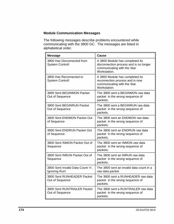
174 03-914731-00:6
Module Communication Messages
The following messages describe problems encountered while communicating with the 3800 GC. The messages are listed in alphabetical order.
Message Cause 3800 Has Disconnected from System Control!
A 3800 Module has completed its disconnection process and is no longer communicating with the Star Workstation.
3800 Has Reconnected to System Control!
A 3800 Module has completed its reconnection process and is now communicating with the Star Workstation.
3800 Sent BEGINMON Packet Out of Sequence
The 3800 sent a BEGINMON raw data packet in the wrong sequence of packets.
3800 Sent BEGINRUN Packet Out of Sequence
The 3800 sent a BEGINRUN raw data packet in the wrong sequence of packets.
3800 Sent ENDMON Packet Out of Sequence
The 3800 sent an ENDMON raw data packet in the wrong sequence of packets.
3800 Sent ENDRUN Packet Out of Sequence
The 3800 sent an ENDRUN raw data packet in the wrong sequence of packets.
3800 Sent INMON Packet Out of Sequence
The 3800 sent an INMON raw data packet in the wrong sequence of packets.
3800 Sent INRUN Packet Out of Sequence
The 3800 sent an INRUN raw data packet in the wrong sequence of packets.
3800 Sent Invalid Data Count 'n'; Ignoring Run!
The 3800 sent an invalid data count in a raw data packet.
3800 Sent RUNHEADER Packet Out of Sequence
The 3800 sent a RUNHEADER raw data packet in the wrong sequence of packets.
3800 Sent RUNTRAILER Packet Out of Sequence
The 3800 sent a RUNTRAILER raw data packet in the wrong sequence of packets.
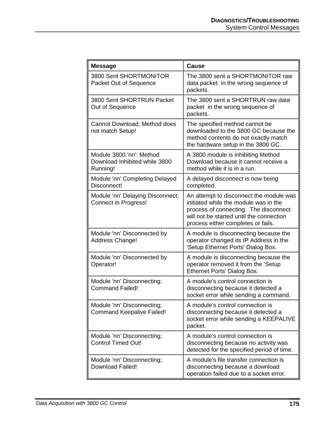
DIAGNOSTICS/TROUBLESHOOTING System Control Messages
Data Acquisition with 3800 GC Control 175
Message Cause 3800 Sent SHORTMONITOR Packet Out of Sequence
The 3800 sent a SHORTMONITOR raw data packet in the wrong sequence of packets.
3800 Sent SHORTRUN Packet Out of Sequence
The 3800 sent a SHORTRUN raw data packet in the wrong sequence of packets.
Cannot Download; Method does not match Setup!
The specified method cannot be downloaded to the 3800 GC because the method contents do not exactly match the hardware setup in the 3800 GC.
Module 3800.'nn': Method Download Inhibited while 3800 Running!
A 3800 module is inhibiting Method Download because it cannot receive a method while it is in a run.
Module 'nn' Completing Delayed Disconnect!
A delayed disconnect is now being completed.
Module 'nn' Delaying Disconnect; Connect in Progress!
An attempt to disconnect the module was initiated while the module was in the process of connecting. The disconnect will not be started until the connection process either completes or fails.
Module 'nn' Disconnected by Address Change!
A module is disconnecting because the operator changed its IP Address in the 'Setup Ethernet Ports' Dialog Box.
Module 'nn' Disconnected by Operator!
A module is disconnecting because the operator removed it from the 'Setup Ethernet Ports' Dialog Box.
Module 'nn' Disconnecting; Command Failed!
A module's control connection is disconnecting because it detected a socket error while sending a command.
Module 'nn' Disconnecting; Command Keepalive Failed!
A module's control connection is disconnecting because it detected a socket error while sending a KEEPALIVE packet.
Module 'nn' Disconnecting; Control Timed Out!
A module's control connection is disconnecting because no activity was detected for the specified period of time.
Module 'nn' Disconnecting; Download Failed!
A module's file transfer connection is disconnecting because a download operation failed due to a socket error.
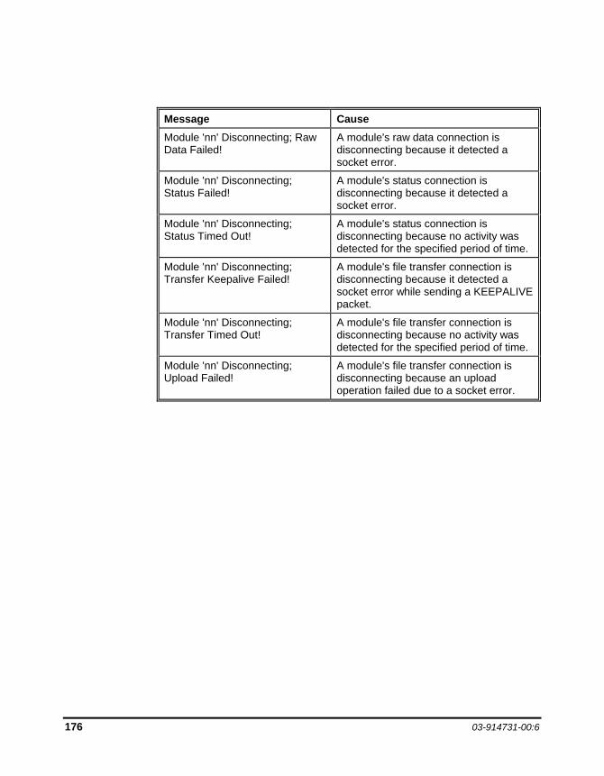
176 03-914731-00:6
Message Cause Module 'nn' Disconnecting; Raw Data Failed!
A module's raw data connection is disconnecting because it detected a socket error.
Module 'nn' Disconnecting; Status Failed!
A module's status connection is disconnecting because it detected a socket error.
Module 'nn' Disconnecting; Status Timed Out!
A module's status connection is disconnecting because no activity was detected for the specified period of time.
Module 'nn' Disconnecting; Transfer Keepalive Failed!
A module's file transfer connection is disconnecting because it detected a socket error while sending a KEEPALIVE packet.
Module 'nn' Disconnecting; Transfer Timed Out!
A module's file transfer connection is disconnecting because no activity was detected for the specified period of time.
Module 'nn' Disconnecting; Upload Failed!
A module's file transfer connection is disconnecting because an upload operation failed due to a socket error.
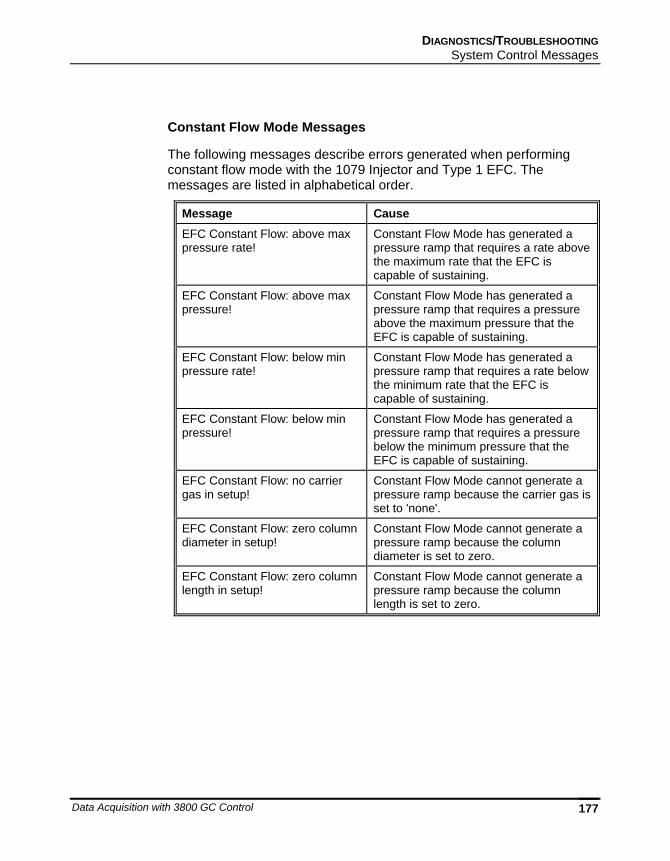
DIAGNOSTICS/TROUBLESHOOTING System Control Messages
Data Acquisition with 3800 GC Control 177
Constant Flow Mode Messages
The following messages describe errors generated when performing constant flow mode with the 1079 Injector and Type 1 EFC. The messages are listed in alphabetical order.
Message Cause EFC Constant Flow: above max pressure rate!
Constant Flow Mode has generated a pressure ramp that requires a rate above the maximum rate that the EFC is capable of sustaining.
EFC Constant Flow: above max pressure!
Constant Flow Mode has generated a pressure ramp that requires a pressure above the maximum pressure that the EFC is capable of sustaining.
EFC Constant Flow: below min pressure rate!
Constant Flow Mode has generated a pressure ramp that requires a rate below the minimum rate that the EFC is capable of sustaining.
EFC Constant Flow: below min pressure!
Constant Flow Mode has generated a pressure ramp that requires a pressure below the minimum pressure that the EFC is capable of sustaining.
EFC Constant Flow: no carrier gas in setup!
Constant Flow Mode cannot generate a pressure ramp because the carrier gas is set to 'none'.
EFC Constant Flow: zero column diameter in setup!
Constant Flow Mode cannot generate a pressure ramp because the column diameter is set to zero.
EFC Constant Flow: zero column length in setup!
Constant Flow Mode cannot generate a pressure ramp because the column length is set to zero.
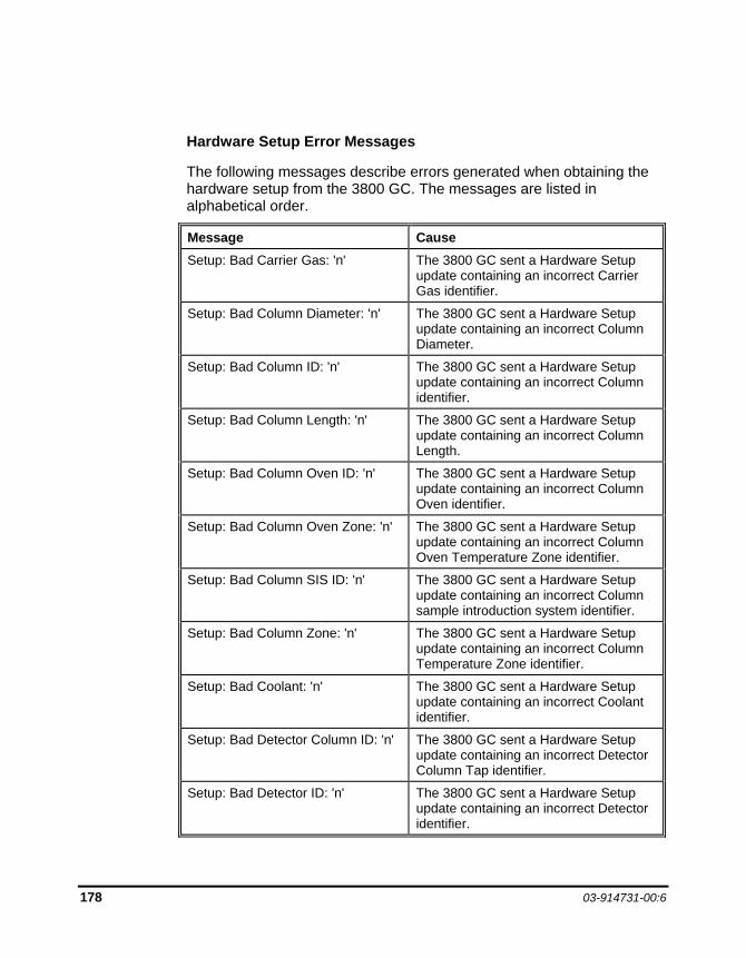
178 03-914731-00:6
Hardware Setup Error Messages
The following messages describe errors generated when obtaining the hardware setup from the 3800 GC. The messages are listed in alphabetical order.
Message Cause Setup: Bad Carrier Gas: 'n' The 3800 GC sent a Hardware Setup
update containing an incorrect Carrier Gas identifier.
Setup: Bad Column Diameter: 'n' The 3800 GC sent a Hardware Setup update containing an incorrect Column Diameter.
Setup: Bad Column ID: 'n' The 3800 GC sent a Hardware Setup update containing an incorrect Column identifier.
Setup: Bad Column Length: 'n' The 3800 GC sent a Hardware Setup update containing an incorrect Column Length.
Setup: Bad Column Oven ID: 'n' The 3800 GC sent a Hardware Setup update containing an incorrect Column Oven identifier.
Setup: Bad Column Oven Zone: 'n' The 3800 GC sent a Hardware Setup update containing an incorrect Column Oven Temperature Zone identifier.
Setup: Bad Column SIS ID: 'n' The 3800 GC sent a Hardware Setup update containing an incorrect Column sample introduction system identifier.
Setup: Bad Column Zone: 'n' The 3800 GC sent a Hardware Setup update containing an incorrect Column Temperature Zone identifier.
Setup: Bad Coolant: 'n' The 3800 GC sent a Hardware Setup update containing an incorrect Coolant identifier.
Setup: Bad Detector Column ID: 'n' The 3800 GC sent a Hardware Setup update containing an incorrect Detector Column Tap identifier.
Setup: Bad Detector ID: 'n' The 3800 GC sent a Hardware Setup update containing an incorrect Detector identifier.
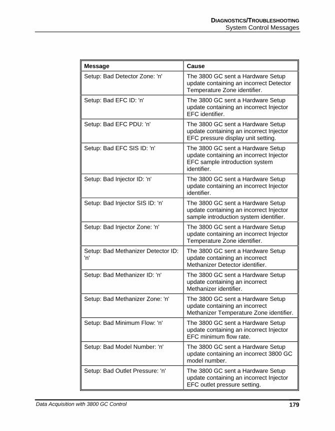
DIAGNOSTICS/TROUBLESHOOTING System Control Messages
Data Acquisition with 3800 GC Control 179
Message Cause Setup: Bad Detector Zone: 'n' The 3800 GC sent a Hardware Setup
update containing an incorrect Detector Temperature Zone identifier.
Setup: Bad EFC ID: 'n' The 3800 GC sent a Hardware Setup update containing an incorrect Injector EFC identifier.
Setup: Bad EFC PDU: 'n' The 3800 GC sent a Hardware Setup update containing an incorrect Injector EFC pressure display unit setting.
Setup: Bad EFC SIS ID: 'n' The 3800 GC sent a Hardware Setup update containing an incorrect Injector EFC sample introduction system identifier.
Setup: Bad Injector ID: 'n' The 3800 GC sent a Hardware Setup update containing an incorrect Injector identifier.
Setup: Bad Injector SIS ID: 'n' The 3800 GC sent a Hardware Setup update containing an incorrect Injector sample introduction system identifier.
Setup: Bad Injector Zone: 'n' The 3800 GC sent a Hardware Setup update containing an incorrect Injector Temperature Zone identifier.
Setup: Bad Methanizer Detector ID: 'n'
The 3800 GC sent a Hardware Setup update containing an incorrect Methanizer Detector identifier.
Setup: Bad Methanizer ID: 'n' The 3800 GC sent a Hardware Setup update containing an incorrect Methanizer identifier.
Setup: Bad Methanizer Zone: 'n' The 3800 GC sent a Hardware Setup update containing an incorrect Methanizer Temperature Zone identifier.
Setup: Bad Minimum Flow: 'n' The 3800 GC sent a Hardware Setup update containing an incorrect Injector EFC minimum flow rate.
Setup: Bad Model Number: 'n' The 3800 GC sent a Hardware Setup update containing an incorrect 3800 GC model number.
Setup: Bad Outlet Pressure: 'n' The 3800 GC sent a Hardware Setup update containing an incorrect Injector EFC outlet pressure setting.

180 03-914731-00:6
Message Cause Setup: Bad Output Port ID: 'n' The 3800 GC sent a Hardware Setup
update containing an incorrect Output Port identifier.
Setup: Bad SW Version: 'n' The 3800 GC sent a Hardware Setup update containing an incorrect software version number.
Setup: Bad Temp Limit: 'n' The 3800 GC sent a Hardware Setup update containing an incorrect Temperature Limit.
Setup: Bad Valve Bank ID: 'n' The 3800 GC sent a Hardware Setup update containing an incorrect valve bank identifier.
Setup: Bad Valve ID: 'n' The 3800 GC sent a Hardware Setup update containing an incorrect valve identifier.
Setup: Bad Valve Oven ID: 'n' The 3800 GC sent a Hardware Setup update containing an incorrect Valve Oven identifier.
Setup: Bad Valve Oven Zone: 'n' The 3800 GC sent a Hardware Setup update containing an incorrect Valve Oven Temperature Zone identifier.
Setup: Bad Valve SIS ID: 'n' The 3800 GC sent a Hardware Setup update containing an incorrect valve sample introduction system identifier.
Setup: Bad Valve Temp Zone: 'n' The 3800 GC sent a Hardware Setup update containing an incorrect valve temperature zone identifier.
Setup: Bad Zone ID: 'n' The 3800 GC sent a Hardware Setup update containing an incorrect Temperature Zone identifier.

DIAGNOSTICS/TROUBLESHOOTING System Control Messages
Data Acquisition with 3800 GC Control 181
3800 GC Runlog Error Messages
The following messages describe errors obtained from the 3800 GC and documented in the Runlog. The messages are listed in alphabetical order.
Message Cause Air Leak Fault The 3800 just detected that the
specified TCD has a disabling air leak.
Board Failure The 3800 just detected that the specified PFPD has a failed electronics board.
Coolant Timed Out The 3800 just detected that the specified component's Temperature Zone Coolant has timed out.
Data Loss due to Workstation Disconnect
The 3800 just detected that its raw data buffer has overflowed because it was unable to transmit its contents to the Star Workstation quickly enough.
Flame-out The 3800 just detected that the specified FID has a flame-out.
Large Air Leak The 3800 just detected that the specified TCD has a large air leak.
Lower than Minimum Temp The 3800 just detected that the specified component's Temperature Zone has gone below its minimum temperature.
Max Setup Temperature Limit Exceeded
The 3800 just detected that the specified component's Temperature Zone has exceeded its maximum Setup temperature limit.
Maximum Temp has been exceeded
The 3800 just detected that the specified component's Temperature Zone has exceeded its maximum temperature.
No Response from Temp Probe The 3800 just detected that the specified component's Temperature Zone Probe is not responding.
Temp Probe is Open The 3800 just detected that the specified component's Temperature Zone Probe has an open circuit.
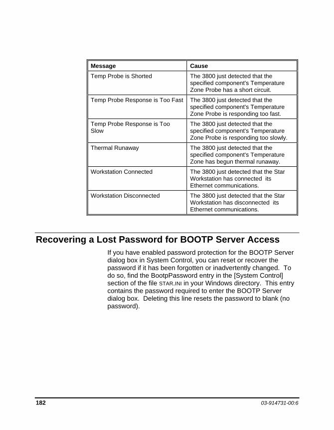
182 03-914731-00:6
Message Cause Temp Probe is Shorted The 3800 just detected that the
specified component's Temperature Zone Probe has a short circuit.
Temp Probe Response is Too Fast The 3800 just detected that the specified component's Temperature Zone Probe is responding too fast.
Temp Probe Response is Too Slow
The 3800 just detected that the specified component's Temperature Zone Probe is responding too slowly.
Thermal Runaway The 3800 just detected that the specified component's Temperature Zone has begun thermal runaway.
Workstation Connected The 3800 just detected that the Star Workstation has connected its Ethernet communications.
Workstation Disconnected The 3800 just detected that the Star Workstation has disconnected its Ethernet communications.
Recovering a Lost Password for BOOTP Server Access If you have enabled password protection for the BOOTP Server dialog box in System Control, you can reset or recover the password if it has been forgotten or inadvertently changed. To do so, find the BootpPassword entry in the [System Control] section of the file STAR.INI in your Windows directory. This entry contains the password required to enter the BOOTP Server dialog box. Deleting this line resets the password to blank (no password).