Embed Size (px)
Citation preview
POWER DISTRIBUTION MODULE
Dashboard Software User Manual Thank you for your purchase. We’ve designed the PDM60 with you, the user in mind. The information below will provide you with all the information you need to successfully configure a setup, and load it into you PDM60 module.
A few very simple parameters are used to configure the PDM60. 1) Select a Circuit Behavior Mode for each circuit 2) Set the current limit for each circuit (10A max on circuits 2,3,6 - 15A max on circuits 1&4 - 20A max on circuit #5) 3) Set the time parameters for delayed startup, and delayed deactivation. (if you have selected delayed on/off features)
1) Circuit Behavior Mode (assign one mode for each of the six PDM60 circuits) The circuit mode is the basic parameter used to set how each circuit operates; when and how a circuit turns on or off. The eight available options are shown below.
INACTIVE Deactivated – Temporarily Disabled – Not Used ALWAYS LIVE - Active – Always On – Constant Power (power is briefly interrupted on ignition trigger) *** WARNING *** (USING THIS CONFIGURATION WILL RESULT IN A CONSTANT PARASITIC CURRENT DRAW OF 50mA – IT IS NOT RECOMMENDED FOR MOTORCYCLE, OR UTILITY BATTERIES WITH LESS THAN A 10Ah RATING – THIS CONFIGRATION IS NOT RECOMMENDED FOR VEHICLES THAT ARE USED INFREQUENTLY, OR IN STORAGE FOR PERIODS EXCEEDING 6 DAYS (WITHOUT A CHARGING
SYSTEM/BATTERY TENDER BEING CONNECTED) The 50mA current draw equates to a battery usage of roughly 1.2 amps per day – Divide your vehicle battery Amp Hour rating by 1.5 – The resulting number is the number of days you will have before your battery is reduced to a discharged state. (i.e 10Ah battery - 10/1.5=6 – days until a discharged condition in present) IGNITION TRIGGER - Ignition trigger activation / deactivation (gray wire to/from + voltage) IGNITION TRIGGER - Ignition trigger activation / deactivation (gray wire to/from + voltage) WITH TIME DELAY OFF AUX TRIGGER – Aux trigger activation / deactivation (Blue wire to/from any ground connection) IGN OR AUX TRIGGER - Ignition trigger (gray wire to + voltage) OR AUX trigger (Blue wire to ground) activation IGN OR AUX TRIGGER - Ignition trigger (gray wire to + voltage) OR AUX trigger (Blue wire to ground) activation WITH TIME DELAY OFF IGNITION AND AUX TRIGGER – Both the Ignition Trigger (gray wire to/from + voltage) AND AUX trigger (Blue wire to/from ground) activation
2) Current Limit – Circuit Capacity (set for each circuit) A current limit is assigned to each of the six circuits. This sets the maximum current allowed to flow through the circuit. Electrically exceeding this setting will cause the circuit to automatically interrupt, protecting your accessory, and more importantly, your vehicle. Current limits can be set (in 1A increments) from 1A up to 10A on circuits 2,3,6, from 1A to 15A on circuits 1 &4, and 1A-20A on circuit #5. (max total of 60Amps) A 20A setting on circuit #5 should only be used for intermittent applications. (high amp horns, etc.) See the specifications on your accessory to determine the best setting for the circuit through which you are powering it. To allow for slight variances, it’s typically advisable to set the current limit with a slight margin (25-30%) above the standard current draw of any accessory. This is only a guideline recommendation, and you should always check with the manufacturer of your accessory to determine the best setting.
3) "Delay On" and "Delay Off" Settings Both of these settings are shown in “seconds”. Delay On - This setting will apply to all circuits. The feature allows for all of the available power on your vehicle to be directed at starting, prior to powering your accessories. After an initial startup trigger signal is received, the PDM60 unit will wait this period of time before fully activating and powering accessories. This delay can be set from “0” seconds (no delay) on up to “240” seconds (four minutes). Delay Off - This setting applies to all circuits configured with a “time delayed off” setting. The maximum available delay is 600 seconds. (10 minutes) When the triggering signal for a circuit is no longer present (as in a key-off scenario), the circuit will remain live for the specified period of time. This feature is useful for communications equipment, GPS, and a variety of other electronics. Once the set period of time is exhausted, the circuit will automatically turn off.
The information above should provide you with a solid understanding of the programming features available on the PDM60. The following will provide instruction on system requirements and the proper use of the dashboard programming tool.
EVOLVE.
Introduction
This software, along with the Rowe Electronics Programming Tool will allow you to custom program the operation of the Rowe Electronics PDM60 Power Distribution Module.
What You Will Need Personal computer running Windows7 or Windows XP with one free USB port
.Net Framework Installed (version 4) Download location: .Net 4 Download site FTDI Device Drivers (most newer computers have this capability) Download location: FTDI Drivers
PDM60 Dashboard Installer file Download location: www.rowe-electronics.com Rowe Electronics Programming Cable (included with unit) Rowe Electronics PDM60 Power Distribution Module
Installing the Software 1) Load, and then locate the PDM60 Dashboard Installer file on your computer (“setup_PDM60Dashboard.exe”) 2) Double-click on this file to start it. 3) Follow the instructions within the installer to complete the installation.
Running the Software 1) Using the Start Menu or the desktop icon that you may have allowed the installer to create, start the program. If using the Start Menu, you will find it in the Rowe folder. 2) IMPORTANT - Plug the PDM60 programming cable into an available USB port on your computer (*** Important: Do not have the cable connected to the PDM60 unit when plugging the cable into your computer) Install the cable. You may need to run the “add new hardware” wizard, and load new FTDI drivers.
3) Set Programming Options – Click “File”, and then “Options”. Make sure the default “programming tool” is set to the PDM60 Programming Cable option. You computer will look for the programming cable. Under the COM Port tab, select the appropriate COM Port tab for the USB port where you have installed the cable. Once complete, click “Ok” You’re now ready to configure the unit.
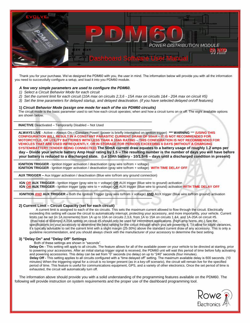
3) In the Dashboard window, select the desired switching mode, and set a current limit for each circuit. Set the time parameters for delay-on/off circuit behavior. The startup delay setting applies to ALL circuits. The shutoff delay applies ONLY to those circuits configured with a “time delay off” switching mode.
3) Once you have the desired operation configured, you’re ready to load the program into the PDM60 unit. You can save the configuration for future use/reference. Click File > Save > type filename -- Leave the extension of the file as “.red” so it can be easily found when you attempt to retrieve it later on. To retrieve, Click File > Open > filename -- The default/stock configuration can be retrieved at any time as well. Click File > Restore Default -- The dashboard will auto-fill with the stock configuration.
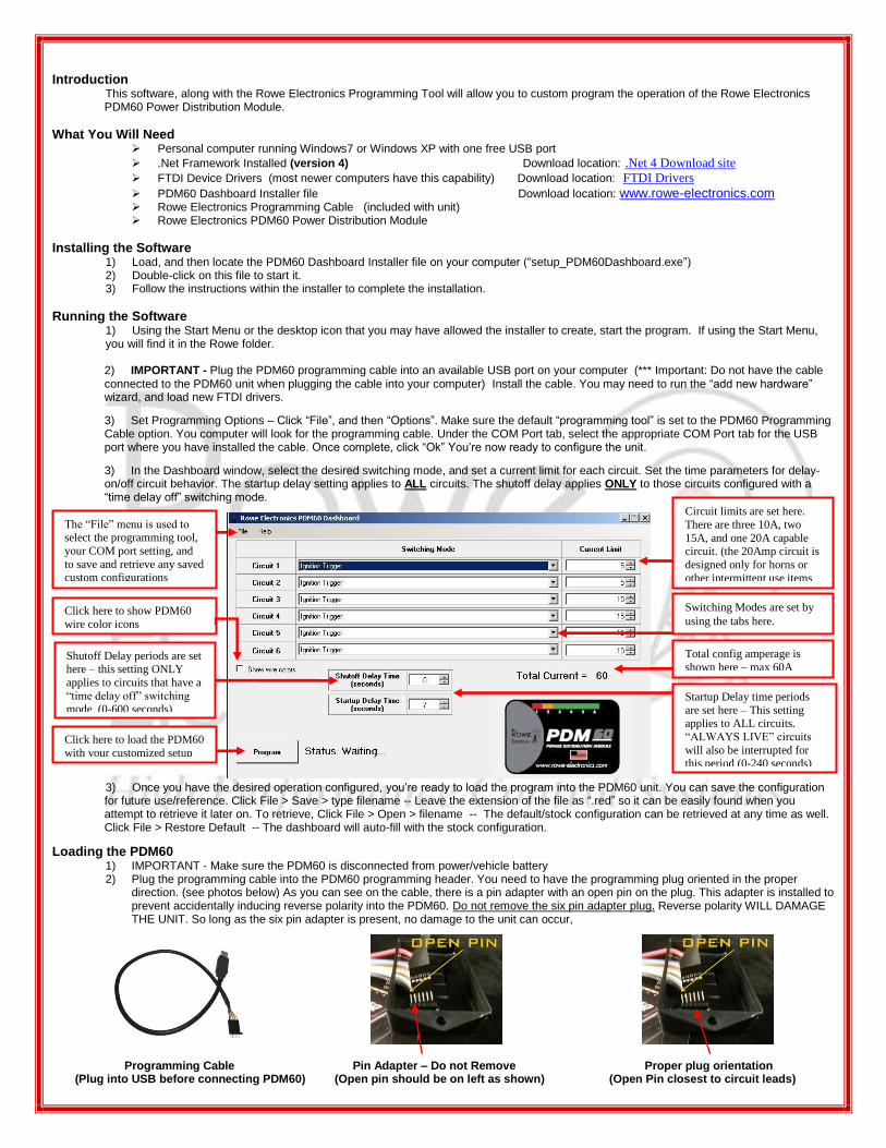
Loading the PDM60 1) IMPORTANT - Make sure the PDM60 is disconnected from power/vehicle battery 2) Plug the programming cable into the PDM60 programming header. You need to have the programming plug oriented in the proper
direction. (see photos below) As you can see on the cable, there is a pin adapter with an open pin on the plug. This adapter is installed to prevent accidentally inducing reverse polarity into the PDM60. Do not remove the six pin adapter plug. Reverse polarity WILL DAMAGE THE UNIT. So long as the six pin adapter is present, no damage to the unit can occur,
Programming Cable Pin Adapter – Do not Remove Proper plug orientation (Plug into USB before connecting PDM60) (Open pin should be on left as shown) (Open Pin closest to circuit leads)
Circuit limits are set here.
There are three 10A, two
15A, and one 20A capable circuit. (the 20Amp circuit is
designed only for horns or
other intermittent use items
Total config amperage is
shown here – max 60A
Switching Modes are set by
using the tabs here.
The “File” menu is used to select the programming tool,
your COM port setting, and
to save and retrieve any saved custom configurations
Click here to show PDM60
wire color icons
Startup Delay time periods
are set here – This setting applies to ALL circuits.
“ALWAYS LIVE” circuits
will also be interrupted for this period (0-240 seconds)
Shutoff Delay periods are set here – this setting ONLY
applies to circuits that have a
“time delay off” switching mode (0-600 seconds)
Click here to load the PDM60
with your customized setup

3) Click the “Program” button on the PDM60 Dashboard window. If everything is properly connected, the firmware for the PDM60 will be downloaded from the computer to the PDM60. This will take several seconds. Do not remove the programming cable until the process is complete. Successful loading/completion will be indicated in the status message next to the “Program” button.
4) If you click Program and there are issues that prevent the PDM60 from being properly programmed, message boxes will appear that should give you information on what error was detected and how to fix it.
5) After programming has completed successfully, unplug the programming cable from the PDM60. 6) Power up the PDM60 and verify that all circuits operate as desired.
Programming Troubleshooting Guide
If you are having difficulty getting your unit to program effectively, taking the following measures should allow you to proceed with successful programming. Programming is a fairly simple process, and validating that all of the potential issues listed here are ruled out, should solve your problems. The most common problems are:
1) Incorrect COM port assignment 2) Poor electrical connections 3) Failure to have either .NET 4 Framework or the required FTDI drivers for the programming cable installed
Check these factors
1) Verify the programming connector is being inserted into the PDM60 with the proper orientation (see above) 2) Verify connections at both ends of the programming cable. 3) Verify the pins in the programming plug are making solid connections inside of the PDM60 programming header. Occasionally, it may
help to put a slight amount of lateral pressure to the side of the programming cable connector while trying to program. 4) Verify that the appropriate COM port been selected in the dashboard “Options” menu. Incorrect COM port assignment will cause
programming failure. An easy way to check this is to remove the cable from your computer USB port. Open the dashboard software and note what COM options are present. Close the dashboard program. Insert the programming cable into the USB port, and open the dashboard program again. See what new COM port appears. A newly appearing COM port is your programming cable port. If no new COM ports appear, you’ll want to make sure the cable, and drivers have been installed. Some computers, when an incorrect COM port is designated, will cause false “programming successful” messages to appear during programming. If your unit is not operating as you programmed it, chances are, this is the problem.
5) Is the PDM60 disconnected from Power/Vehicle battery? (you should always disconnect power to reprogram) 6) Is .Net framework 4 installed on your PC/Laptop? 7) Do you have the appropriate FTDI drivers installed?
If you have ruled out all of the factors above, and still are in need of additional assistance, feel free send an e-mail to us at [email protected] and we will answer as quickly as possible. You may also be able to get direct, immediate support by calling the dealer that sold the unit to you, or by calling our office during normal business hours. We’ll always do whatever we can to make your installation and ownership experience a favorable one.
We’ve designed the PDM unit to be versatile, user friendly, and most importantly, highly dependable. It’s simple to program,
simple to install. It makes the old methods of powering accessories and protecting a vehicle look like antiquated technology…and that’s because it is. One you’re done programming and installing the unit, it is official.
You have Evolved.
339 Hakes Drive Norwalk, Ia. 50211
Contact Info: info@ rowe-electronics.com
www.rowe-electronics.com