Embed Size (px)
DESCRIPTION
Daniel Kellett 635876 - ABPL30048 - Architecture Design Studio: Air - University of Melbourne
Citation preview

AIRDESIGN JOURNAL | ABPL 30048 | DANIEL KELLETT 635876 | SEM 1 2015

DESIGN JOURNAL | ABPL 30048 ARCHITECTURE DESIGN STUDIO: AIR SEMESTER 1 2015 | DANIEL KELLETT 635876 | TUTORS: CHEN CANHUI & ROSIE

DESIGN JOURNAL | ABPL 30048 ARCHITECTURE DESIGN STUDIO: AIR SEMESTER 1 2015 | DANIEL KELLETT 635876 | TUTORS: CHEN CANHUI & ROSIE
AIR
Contents
1 Introduction 8 - 9 Part A: Conceptualisation
10 - 11 A1.0 Design Futuring: Overview12 - 13 A1.1 Precedent Project: Renzo Piano, Pathe Foundation Headquarters14 - 15 A1.2 Precedent Project: Zaha Hadid, Dongdaemun Design Plaza
16 - 17 A2.0 Design Computation: Overview18 - 19 A2.1 Precedent Project: SHoP Architects, The Porter House20 - 21 A2.2 Precedent Project: University of Stuttgart Research Pavilion 2013/14
22 - 23 A3.0 Generation/Composition: Overview24 - 25 A3.1 Precedent Project: IAAC, Endesa Pavilion26 - 27 A3.2 Precedent Project: NBBJ Architects, Hangzhou Olympic Sports Centre
28 - 29 Summary
30 A4.0 Conclusion31 A5.0 Learning Outcomes
32 - 33 Part B: Criteria Design
34 - 35 B1.0 Research Field: Geometry36 - 37 B1.1 Precedent Project: SmartGeometry, 2012 Gridshell38 - 39 B1.2 Precedent Project: SJET, Voltadom
40 - 41 B2.0 Case Study 1: The Green Void42 - 43 B2.1 LAVA, The Green Void Overview44 - 45 Script Exploration: Series 1 + 246 - 47 Script Exploration: Series 3 + 448 - 49 B2.2 Iteration Selection Criteria
50 - 51 B3.0 Case Study 2: Canton Tower52 - 53 B3.1 Information Based Architecture (IBA), Canton Tower Overview54 - 55 B3.2 Reverse Engineer Progression56 - 57 B3.3 Selective Imagery: Reverse Engineer
58 - 59 B4.0 Technique Development60 - 61 B4.1 Script Exploration - Set 162 - 63 Script Exploration - Set 264 - 65 B4.2 Iteration Selection Criteria
66 - 67 B5.0 Technique Prototype68 - 71 B5.1 Prototype Development
72 - 73 B6.0 Technique Proposal74 - 75 B6.1 Consolidating Progression76 - 77 B6.2 Site Information/Background78 - 79 B6.3 Site Visit/Exploration80 - 81 B6.4 Site Usage82 - 83 B6.5 Potential Design Locations - Ceres Environmental Park84 - 85 B6.6 Chosen Design Location - Design Proposal
86 - 87 Summary
86 B7.0 Interim Submission Feedback87 B7.1 Learning Objectives
88 - 89 Part C: Detailed Design
90 -91 C1.0 Analysing Progress92 - 97 C1.1 Refining the Site98 - 99 C1.2 Melbourne Water Usage Statistics100 - 101 C1.3 Mission Statements - CERES + Team102 - 105 C1.4 Diagrammatic Goals + Ideas
106 - 107 C2.0 Form Precedents108 - 113 C2.1 Iteration Development114 - 119 C2.2 Final Form Renders
120 - 121 C3.0 Construction Development122 -123 C3.1 Surface Precedents124 - 125 C3.2 Materiality
126 - 127 C4.0 Prototypes128 - 129 C4.1 Attempt 1130 - 131 C4.2 Attempt 2
132 - 139 C5.0 Fabrication + Construction140 - 145 C5.1 Construction Process
146 - 147 C6.0 DRIP TIES148 - 149 C6.1 Statistics150 - 167 C6.2 Presentation
168 - 169 Summary
170 - 188 Algorithmic Sketchbook Inclusions + References
6
02
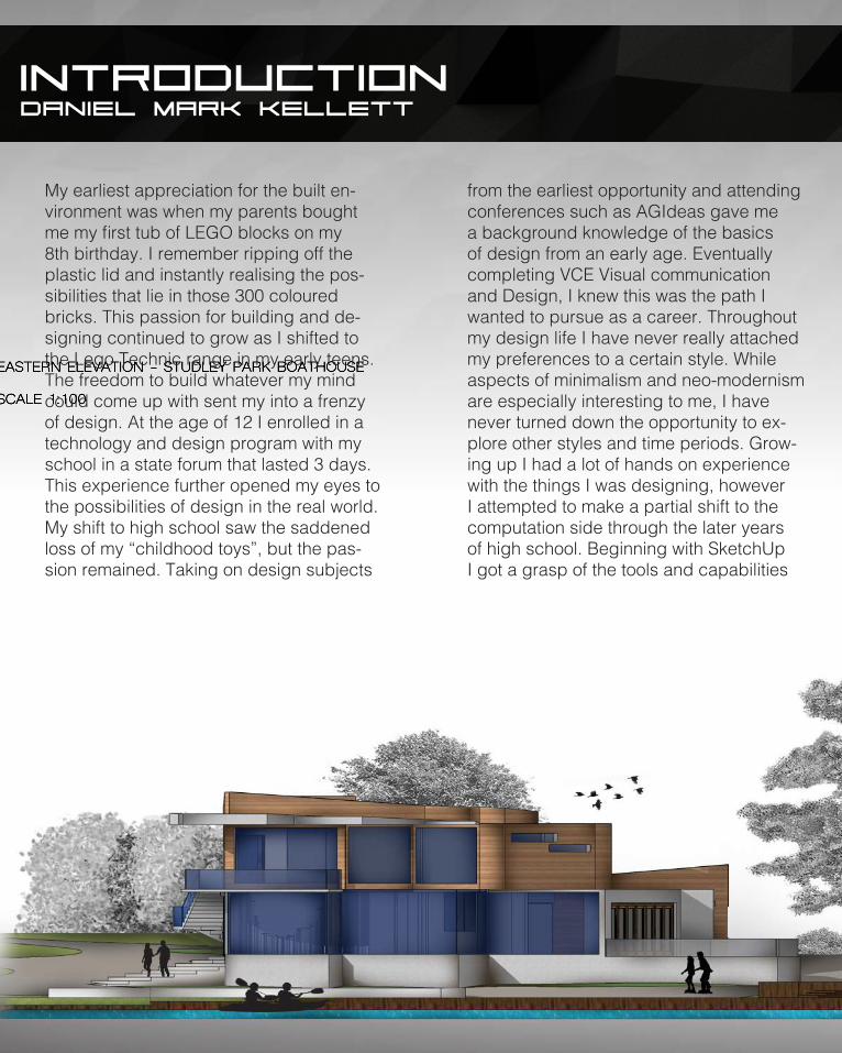
EASTERN ELEVATION - STUDLEY PARK BOATHOUSE
SCALE 1:100
WESTERN ELEVATION - STUDLEY PARK BOATHOUSE
SCALE 1:100
NORTHERN ELEVATION - STUDLEY PARK BOATHOUSE
SCALE 1:100
STUDLEY PARK BOATHOUSE | MASTER ARCHITECTUREARCHITECTURE DESIGN STUDIO: WATER FINAL PRESENTATION ABPL20028 SEM 2 2014S: DANIEL KELLETT 635876T: NAFISEH HAMIDI
IntroductionDaniel Mark Kellett
Current Position: Undergraduate Student
Institution: The University of Melbourne
Degree: Bachelor of Environments
Major: Architecture
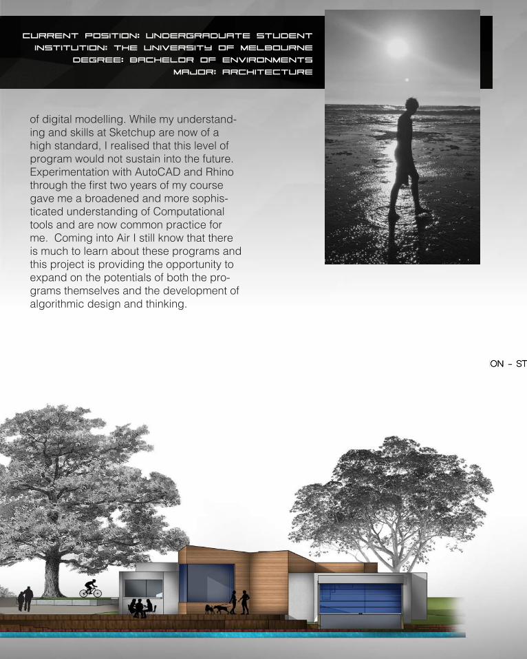
My earliest appreciation for the built en-vironment was when my parents bought me my first tub of LEGO blocks on my 8th birthday. I remember ripping off the plastic lid and instantly realising the pos-sibilities that lie in those 300 coloured bricks. This passion for building and de-signing continued to grow as I shifted to the Lego Technic range in my early teens. The freedom to build whatever my mind could come up with sent my into a frenzy of design. At the age of 12 I enrolled in a technology and design program with my school in a state forum that lasted 3 days. This experience further opened my eyes to the possibilities of design in the real world. My shift to high school saw the saddened loss of my “childhood toys”, but the pas-sion remained. Taking on design subjects
from the earliest opportunity and attending conferences such as AGIdeas gave me a background knowledge of the basics of design from an early age. Eventually completing VCE Visual communication and Design, I knew this was the path I wanted to pursue as a career. Throughout my design life I have never really attached my preferences to a certain style. While aspects of minimalism and neo-modernism are especially interesting to me, I have never turned down the opportunity to ex-plore other styles and time periods. Grow-ing up I had a lot of hands on experience with the things I was designing, however I attempted to make a partial shift to the computation side through the later years of high school. Beginning with SketchUp I got a grasp of the tools and capabilities
7
02
EASTERN ELEVATION - STUDLEY PARK BOATHOUSE
SCALE 1:100
WESTERN ELEVATION - STUDLEY PARK BOATHOUSE
SCALE 1:100
NORTHERN ELEVATION - STUDLEY PARK BOATHOUSE
SCALE 1:100
STUDLEY PARK BOATHOUSE | MASTER ARCHITECTUREARCHITECTURE DESIGN STUDIO: WATER FINAL PRESENTATION ABPL20028 SEM 2 2014S: DANIEL KELLETT 635876T: NAFISEH HAMIDI
Current Position: Undergraduate Student
Institution: The University of Melbourne
Degree: Bachelor of Environments
Major: Architecture
of digital modelling. While my understand-ing and skills at Sketchup are now of a high standard, I realised that this level of program would not sustain into the future. Experimentation with AutoCAD and Rhino through the first two years of my course gave me a broadened and more sophis-ticated understanding of Computational tools and are now common practice for me. Coming into Air I still know that there is much to learn about these programs and this project is providing the opportunity to expand on the potentials of both the pro-grams themselves and the development of algorithmic design and thinking.

8
PART A.
CONCEPTUALISATION

9
PART A.
CONCEPTUALISATION
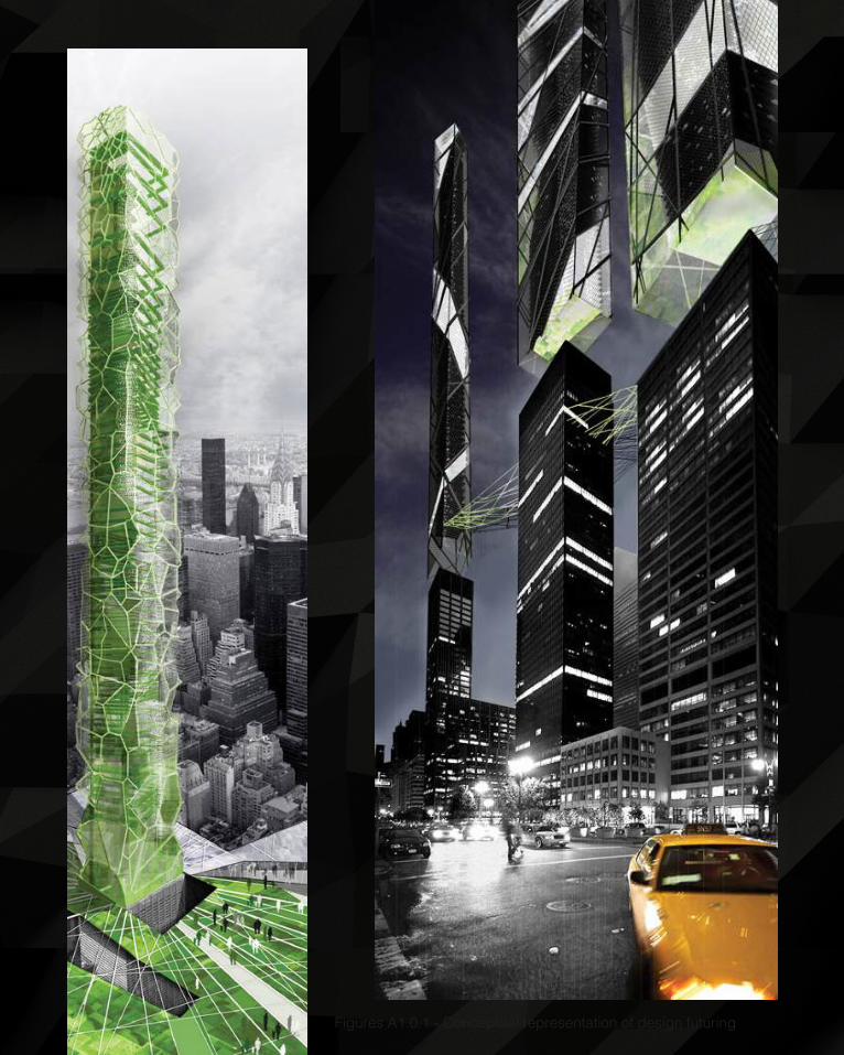
10Figures A1.0.1 - Conceptual representation of design futuring

11
As we move further into the 21st Century the idea of future thinking and how actions can affect this future are becoming ever more prominent in societal and professional thinking. Architecture as a field of practice is forever changing and the need for continued develop-ment is crucial. This is not only key in discovering new innovations and techniques but is it a determinant for the idea of design being considered pivotal in our expression of identity and difference.1
Architecture reflects the ideals and lifestyles of cultures over periods of time. As time and society progress so does its values and character. This reflection in design has been seen throughout history and as we continue to push through the 21st century it is becoming appar-ent that a shift in thinking is needed.
We are in a period where sustainable design and future understanding is needed in order to secure the continued existence of our society. There is a need for designers to now re-think conventional processes and undertake a shift towards innovative and sustainable ways of design practice.
Anthony Vidler stated that a shift in forward thinking from the 20th into the 21st Century can-not occur without disrupting the structure and practice of traditional typologies.2 If continued growth in sustainable practice is to occur, then a shift in thinking and attitude is required. The following precedents are examples that attempt to consider this idea of design futuring and basis for continued innovation.
1 Lian Hurst Mann, Reconstructing Architecture: Critical Discourses and Social Practices, ed. by Thomas A. Dutton, Illustrated edn (Minnesota: U of Minnesota Press, 1996), p. 1.2 Anthony Vidler, Review of Rethinking Architecture and the Anaesthetics of Architecture (United States: Harvard Design Magazine, 2000), p. 3 - 11.
DESIGN FUTURING
12
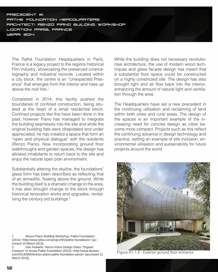
The Pathé Foundation Headquarters in Paris, France is a legacy project to the regions historical Film industry, showcasing the preserved cinema-tography and industrial records. Located within a city block, the centre is an “Unexpected Pres-ence” that emerges from the interior and rises up above the roof line.1
Completed in 2014, this facility pushed the boundaries of confined construction, being situ-ated at the heart of a small residential block. Confined projects like this have been done in the past, however Piano has managed to integrate the building seamlessly into the site and while the original building flats were dilapidated and under appreciated, he has created a space that form an “open and physical dialogue” with the residents (Renzo Piano). Now incorporating ground floor walkthroughs and garden spaces, the design has allowed inhabitants to return back to the site and enjoy the natural open plan environment.
Substantially altering the skyline, the foundations’ glass form has been described as reflecting that of an armadillo, floating above the ground. While the building itself is a dramatic change to the area, it has also brought change to the block through historical renovation works and upgrades, revital-ising the century old buildings.2
1 Renzo Piano Building Workshop, Pathe Foundation (2014) <http://www.rpbw.com/project/81/pathe-foundation/> [ac-cessed 10 March 2015].2 Dan Howarth, Renzo Piano Design Glass “Organic Creature” to house Pathe Foundation (2014) <http://www.dezeen.com/2014/06/04/renzo-piano-pathe-foundation-paris/> [accessed 11 March 2015].
While the building does not necessary revolutio-nise architecture, the use of modern wood tech-niques and glass facade design has meant that a substantial floor space could be constructed on a highly constricted site. The design has also brought light and air flow back into the interior, enhancing the amount of natural light and ventila-tion through the area.
The Headquarters have set a new precedent in the continuing utilisation and reclaiming of land within both cities and rural areas. The design of the spaces is an important example of the in-creasing need for concise design as cities be-come more compact. Projects such as this reflect the continuing advance in design technology and practice, setting an example of site inclusion, en-vironmental utilisation and sustainability for future projects around the world.
PRECEDENT #1
PathEé Foundation Headquarters
Architect: Renzo Piano Building Workshop
Location: Paris, France
Year: 2014
Figure A1.1.2 - Exterior ground floor entrance
13
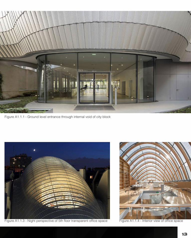
Figure A1.1.1 - Ground level entrance through internal void of city block
Figure A1.1.3 - Night perspective of 5th floor transparent office space Figure A1.1.4 - Interior view of office space

14
1. Zaha Hadid Architects, Dongdaemun Design Plaza (2015) <http://www.zaha-hadid.com/architecture/dongdae-mun-design-park-plaza/?doing_wp_cron> [accessed 12 March 2015].2. Seoul Design Foundation, Introduction of Dongdaemun Design Plaza & Park (2012) <http://www.seouldesign.or.kr/eng/plaza/concept.jsp> [accessed 11 March 2015].
Figure A1.2.1 - Interior hallway seating
Figure A1.2.2 - Exterior view of Facility
15
PRECEDENT #2
Dongdaemun design plaza
Architect: Zaha HadiD | Samoo
Location: Seoul, South Korea
Year: 2014
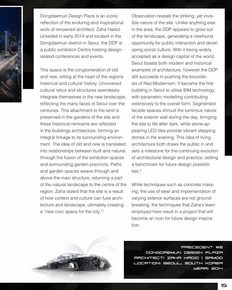
Dongdaemun Design Plaza is an iconic reflection of the enduring and inspirational work of renowned architect, Zaha Hadid. Unveiled in early 2014 and located in the Dongdaemun district in Seoul, the DDP is a public exhibition Centre hosting design-related conferences and events.
This space is the conglomeration of old and new, sitting at the heart of the regions historical and cultural history. Uncovered cultural relics and structures seamlessly integrate themselves in the new landscape, reflecting the many faces of Seoul over the centuries. This attachment to the land is preserved in the gardens of the site and these historical remnants are reflected in the buildings architecture, forming an integral linkage to its surrounding environ-ment. The idea of old and new is translated into relationships between built and natural, through the fusion of the exhibition spaces and surrounding garden precincts. Paths and garden spaces weave through and above the main structure, returning a part of the natural landscape to the centre of the region. Zaha stated that the site is a result of how context and culture can fuse archi-tecture and landscape, ultimately creating a “new civic space for the city.”1
Observation reveals the striking, yet invis-ible nature of the site. Unlike anything else in the area, the DDP appears to grow out of the landscape, generating a newfound opportunity for public interaction and devel-oping social culture. With it being widely accepted as a design capital of the world, Seoul boasts both modern and historical examples of architecture, however the DDP still succeeds in pushing the boundar-ies of Neo-Modernism. It became the first building in Seoul to utilise BIM technology, with parametric modelling contributing extensively to the overall form. Segmented facade spaces shroud the luminous nature of the exterior wall during the day, bringing the site to life after dark, while stone-ap-pearing LED tiles provide vibrant stepping stones in the evening. This idea of living architecture both draws the public in and sets a milestone for the continuing evolution of architectural design and practice; setting a benchmark for future design possibili-ties.2
While techniques such as concrete mass-ing, the use of steel and implementation of varying exterior surfaces are not ground-breaking, the techniques that Zaha’s team employed here result in a project that will become an icon for future design inspira-tion.
16

17
DESIGN COMPUTATION
Descriptions of any aspect of life often result at one point or another in the use of the term “it is just the same as usual”. While many fac-ets of life may appear to be like this, architec-ture has never held this notion. The progres-sion of architectural ideas and practice have been evolving for centuries and more so in the last 50, we have seen a rapid transforma-tion of the way we deal with and share archi-tecture. The advent of the computer nearly half a century ago changed the way in which we interact with the world and has become both an integral part of our lives and a tool in which we employ.
As systems have advanced, so too has the regularity of observing Computer aided design techniques in practices around the world. Today CAD systems are able to pro-duce some of the most amazing designs we have seen with little or no errors. This seam-less ability to integrate technology into the design process is why it has become such a common tool.
Technology is widely accepted to always being one step ahead, as technology is ac-quired something new is already on the mar-ket and this is true in our understanding and learning of technology. While computer aided
design began as a tool in assisting precon-ceived ideas it has now able to become part of the process.
As the complexity of these systems have in-creased so to have the notions of what these systems are and how they are used. Com-puterisation is the use of systems for works that are processing “already conceptualised” ideas and designs.1 These programs are purely used to manipulate and store data for projects. Computerisation can be viewed as sitting beside the design process, rather than integrated into it.
Increasingly accepted however, is the con-cept of Computation, which has generally been confused with the theories of Computer-isation. In contrast to this, Computation takes the programs we use and treats them as a part of the design process. Peter Brady per-ceives computation as a “method of captur-ing and communicating ideas”.2 While many still perceive technological programs as tools, these techniques are allowing designers to produce far more precise and complex work. This ability also stretches further, allowing manufacturing and tracking to be undertaken from these technologies.
1 Kostas Terzidis, Algorithmic Architecture (Great Britain: Elsevier, 2006), p. 11.2 Brady Peters, Computation Works: The Building of Algorithmic Thought from Architectural Design ([n.p.]: , 2013), p. 10.
18
PRECEDENT #3
The Porter House
Architect: SHOP ARCHITECTS
Location: MANHATTAN, NEW YORK
Year: 2003
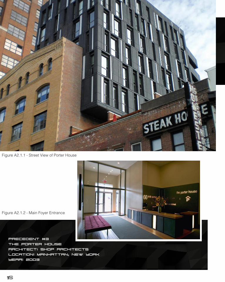
Figure A2.1.1 - Street View of Porter House
Figure A2.1.2 - Main Foyer Entrance
19
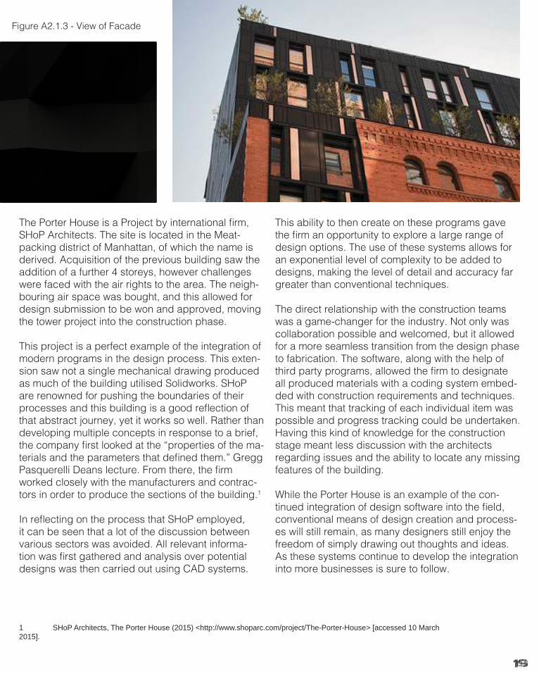
The Porter House is a Project by international firm, SHoP Architects. The site is located in the Meat-packing district of Manhattan, of which the name is derived. Acquisition of the previous building saw the addition of a further 4 storeys, however challenges were faced with the air rights to the area. The neigh-bouring air space was bought, and this allowed for design submission to be won and approved, moving the tower project into the construction phase.
This project is a perfect example of the integration of modern programs in the design process. This exten-sion saw not a single mechanical drawing produced as much of the building utilised Solidworks. SHoP are renowned for pushing the boundaries of their processes and this building is a good reflection of that abstract journey, yet it works so well. Rather than developing multiple concepts in response to a brief, the company first looked at the “properties of the ma-terials and the parameters that defined them.” Gregg Pasquerelli Deans lecture. From there, the firm worked closely with the manufacturers and contrac-tors in order to produce the sections of the building.1
In reflecting on the process that SHoP employed, it can be seen that a lot of the discussion between various sectors was avoided. All relevant informa-tion was first gathered and analysis over potential designs was then carried out using CAD systems.
This ability to then create on these programs gave the firm an opportunity to explore a large range of design options. The use of these systems allows for an exponential level of complexity to be added to designs, making the level of detail and accuracy far greater than conventional techniques.
The direct relationship with the construction teams was a game-changer for the industry. Not only was collaboration possible and welcomed, but it allowed for a more seamless transition from the design phase to fabrication. The software, along with the help of third party programs, allowed the firm to designate all produced materials with a coding system embed-ded with construction requirements and techniques. This meant that tracking of each individual item was possible and progress tracking could be undertaken. Having this kind of knowledge for the construction stage meant less discussion with the architects regarding issues and the ability to locate any missing features of the building.
While the Porter House is an example of the con-tinued integration of design software into the field, conventional means of design creation and process-es will still remain, as many designers still enjoy the freedom of simply drawing out thoughts and ideas. As these systems continue to develop the integration into more businesses is sure to follow.
1 SHoP Architects, The Porter House (2015) <http://www.shoparc.com/project/The-Porter-House> [accessed 10 March 2015].
Figure A2.1.3 - View of Facade
20
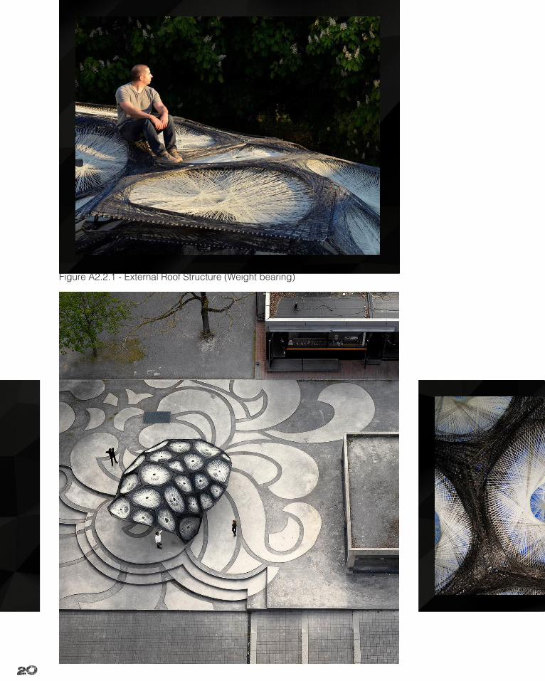
Figure A2.2.1 - External Roof Structure (Weight bearing)
21
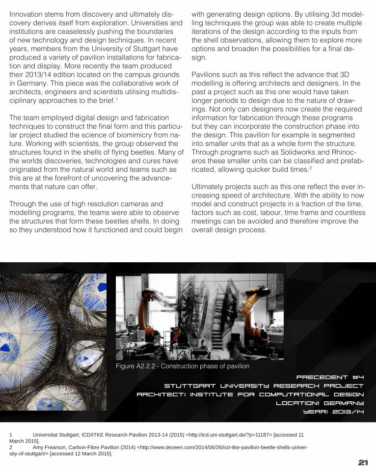
PRECEDENT #4
StuttGart University Research Project
Architect: Institute for computational design
Location: Germany
Year: 2013/14
Innovation stems from discovery and ultimately dis-covery derives itself from exploration. Universities and institutions are ceaselessly pushing the boundaries of new technology and design techniques. In recent years, members from the University of Stuttgart have produced a variety of pavilion installations for fabrica-tion and display. More recently the team produced their 2013/14 edition located on the campus grounds in Germany. This piece was the collaborative work of architects, engineers and scientists utilising multidis-ciplinary approaches to the brief.1
The team employed digital design and fabrication techniques to construct the final form and this particu-lar project studied the science of biomimicry from na-ture. Working with scientists, the group observed the structures found in the shells of flying beetles. Many of the worlds discoveries, technologies and cures have originated from the natural world and teams such as this are at the forefront of uncovering the advance-ments that nature can offer.
Through the use of high resolution cameras and modelling programs, the teams were able to observe the structures that form these beetles shells. In doing so they understood how it functioned and could begin
with generating design options. By utilising 3d model-ling techniques the group was able to create multiple iterations of the design according to the inputs from the shell observations, allowing them to explore more options and broaden the possibilities for a final de-sign.
Pavilions such as this reflect the advance that 3D modelling is offering architects and designers. In the past a project such as this one would have taken longer periods to design due to the nature of draw-ings. Not only can designers now create the required information for fabrication through these programs but they can incorporate the construction phase into the design. This pavilion for example is segmented into smaller units that as a whole form the structure. Through programs such as Solidworks and Rhinoc-eros these smaller units can be classified and prefab-ricated, allowing quicker build times.2
Ultimately projects such as this one reflect the ever in-creasing speed of architecture. With the ability to now model and construct projects in a fraction of the time, factors such as cost, labour, time frame and countless meetings can be avoided and therefore improve the overall design process.
1 Universitat Stuttgart, ICD/ITKE Research Pavilion 2013-14 (2015) <http://icd.uni-stuttgart.de/?p=11187> [accessed 11 March 2015].2 Amy Frearson, Carbon-Fibre Pavilion (2014) <http://www.dezeen.com/2014/06/26/icd-itke-pavilion-beetle-shells-univer-sity-of-stuttgart/> [accessed 12 March 2015].
Figure A2.2.2 - Construction phase of pavilion
22
23
COMPOSITION | GENERATION
There have been many periods in history where events have shifted the direction in which ar-chitecture takes, both in style and process. The advent of advanced computational technology and its continued development over the last 20 years is potentially producing one of these periods. Although specific design styles are not changing, the methods by which we design are evolving.
Conventional hand techniques have in more re-cent times seen the addition of computer aided systems that have been merely a manipulation tool. These digital technologies were based on receiving a preconceived idea from designers that allowed the manipulation and editing of projects, leaving the design outcomes a deci-sion of the designers themselves. This idea of design composition has been utilised increas-ingly in industry because of its ease of use and precision. As Engineering and construction sectors have also advanced, prefabrication and complex construction techniques are now pos-sible. Through collaboration these programs are then able to optimise these processes and both designers and constructors are able to be more efficient and precise, cutting down on costs and completion time frames.
However in more recent times the computational abilities of these systems have reached a far more advanced stage, with the ability for them to undertake more complex and precise tasks that have not previously been possible. Algorith-mic programs such as Grasshopper allow the input of certain features/requirements into their systems that can generate design options in ac-cordance with the parameters. This generation
design has therefore created a new way of per-ceiving the design process. Rather than utilising these systems for manipulation, the programs are in essence generating the design. While the possibilities for large numbers of iterations can now occur, much of the personal connection between designer and design may be lost. In al-lowing generative design to be primarily utilised, much of the design choices are then resolved through these programs, potentially losing some features of a design that might otherwise have been included.
The size of cities and rural areas are increasing more rapidly and there is now more demand for buildings and constructions. There is the poten-tial then for a large volume of future projects to be created in this way because of their value to designers.

24
PRECEDENT #5
Endesa Pavilion
Architect: IAAC | Margen Lab
Location: Barcelona, Spain
Year: 2011
The Endesa Pavilion in Barcelona is a joint project com-pleted in 2011 for the Smart City Congress. The building utilises computational systems to produce the overall form and provides reflection on the capabilities and drawbacks of algorithmic generation within the design process.
This project aimed to provide a space that was both practical and sustainable. Looking at the sun as a source of energy, this feature formed the basis for the overall design. Observing the path of the sun through the sky, the designers documented these details and employed algorithmic computation to produce the optimum form to which this could be fully utilised. The units within the buildings structure acted in two ways, providing the basis for solar technology on the exterior and generating usable space for inhabitants on the interior. This process also allowed the form to be broken down into smaller units and allow prefabrication and installation to become more cost effective and time saving.1
The buildings overall form is generated from the out-comes of the computations done through software and
while personal choice as to which iteration would ulti-mately form the final concept, much of the interaction be-tween designer and form are lost. The individual features that a designer may want to include to improve aesthetics for example, may not eventuate in these computational designs because they would hinder the maximum output of the input information.
In looking particularly at this project it is interesting to note that the sun and its movement were the only fea-tures that determined the form of the structure. While this building is perfect for the purpose of solar capture, there are other potential aspects of the environments that hold as much importance, such as regional wind, exterior temperatures, building material locations as long-distant sourcing and hinder cost savings in form, etc.
While generative approaches to design can produce many iterations and practical forms, the human aspect of design needs to be first considered in its full extent. Lock-ing into a single idea can still produce good designs but may lack the practical application in real life.2
1 Institute For Advanced Architecture, Endesa Pavilion & Research Projects (2009) <http://www.iaac.net/projects/endesa-pavilion-25> [accessed 17 March 2015].2 Fast Co Design, Shaped By Algorithms, A Solar Powered Pavilion That Soaks Up Maximum Rays (2012) <http://www.fastcodesign.com/1670678/shaped-by-algorithms-a-solar-powered-pavilion-that-soaks-up-maximum-rays> [accessed 16 March 2015].
Figure A3.1.1 to 4 - External Views of Facade
25
26

27
PRECEDENT #6
Hangzhou Olympic Sports Centre
Architect: NBBJ | CCDI
Location: Hangzhou, China
Year: 2014/15
Hangzhou Olympic Sports Centre is a recent project by NBBJ in collaboration with CCDI. Their design is the sites competition winning entry and is due to be finished shortly. This building represents the positive outcomes of utilising the generative styles of com-putational tools. The team began by understanding that they were designing a stadium within a sports complex and that certain environmental, structural and personal goals had to be met.
Rather than developing iterations of the form of the building and then systematically making those features integrate practically, the team stripped back conventional techniques and begun by look-ing at the requirements that a stadium must achieve. Features such as seating angle and spatial linkage were researched, allowing the designers to first understand aspects such as how facets interacted, their structural requirements and their potential design forms. This meant that before any computa-tional programming occurred, they understood what the building needed
With this knowledge, they then applied their own design intent and concepts in form and layout, later carrying all this information over to Rhino and Grasshopper programs to facilitate the generation of design options. Key drivers such as steel costs and manufacturing ease were all aspects that were plugged into the software.
Rather than allowing the system to then decide the complete form of the structure the teams influenced aspects to reflect their desired outcomes, but also so that the best outcomes structurally could be produced.
Firstly allowing Grasshopper to solve the structural needs of the building meant that a resulting frame could then be manipulated to the overall aesthetic. The Petal exterior was further altered to the desired pattern and because of its link to the computational software, the structure then updated to compensate for the exterior changes. By working in tandem a final design was produced with ease and collabora-tion with construction teams meant that the build-ings build time frame was shortened as they too had access to these systems.
Projects such as these reflect the incredible poten-tial that software can offer. While it is easy to allow these to ‘answer’ a design problem, the identity in the design and the development of personal at-tributes can simply be lost. NNBJ and CCDI have succeeded in utilising Rhino and Grasshopper for the structural and optimising capabilities but they have worked in unison with this process to guide the programs in the direction they preferred. This way of thinking will most likely continue into the future and result in more sustainable and functional spaces.1
1 NBBJ, A City Blossoms (2015) <http://www.nbbj.com/work/hangzhou-stadium/> [accessed 15 March 2015].
28

29
Summary
30
Part A has explored the ways in which architectural design approaches projects both conventionally and more recently through the advent of the technological age. It therefore stands to look at designing into the future and for a future. Architecture is a reference for the styles of an age and in our understanding of the world and its progress, change can occur to better design in general.
Discussion over the techniques of modern design practice have allowed an under-standing of the processes that are currently occurring the in architectural field. By understanding this and experimenting with these systems a valuable knowledge is gained and can be carried over the process of designing for the Merri Creek Brief. This research has shown the ways in which algorithmic and computational methods can both be beneficial and harmful to the design intent and personal reflection of the designer. By harnessing the capabilities of programs such as Rhino and Grasshop-per, design iterations can be produced both in volume and potential. The ability to then manipulate and add to these designs truly realises the potential for the integra-tion of design computation technology to be integrated into common practice.
In knowing that computational means will be utilised at some point along the design process, a shift in the initial stages of design are required. The Merri Creek brief remains an open palette for potential outcomes however the site features many vary-ing aspects and these can all affect and influence the desired result. Research into the site will allow the potential design locations to become more evident rather than simply choosing and area and designing a form that merely is located there. By first understanding the needs, constraints and potentials of the site, a more well rounded and precise response can be achieved.
In utilising the techniques and styles of design generation, knowledge of the site will allow the creation of a final project that will enhance the chosen location both in form/environment and human interaction and passing. Due to the large human presence in the area, a design that potentially responds to both nature and human usage is ideal in fully realising the sites attributes.
By using a bottom up approach to first understand the site and design according to this, better management of the form can be achieved. This will then mean that in-teraction with spatial elements will be optimal and fabrication and construction can benefit, meaning build time and material requirements will be improved.
Conclusion Learning OUtcomes

31
Conclusion Learning OUtcomes
The design process is heavily generalised and simplified when explained to a wider audience and this perceived understanding creates a notion of the interaction with teams and their designs. In only participating in this subject for 3 weeks now it is in-teresting to note that, while computational design has been used for many years now within this relationship, the extent and varying approaches to this are far greater than previously considered.
By both researching the approaches to design in various locations around the world and physically completing tasks using the same methods, the widespread popular-ity of these methods can be understood. It is easy to see how certain designs are allowed to be fully realised through computational software, however in order to produce more practical, well rounded and researched projects a human-technology relationship must be established in order to both utilise the intent of the designer and the capabilities of the software. This tandem effort means that forms have the poten-tial to be more sustainable but also respond to a brief in a more comprehensive man-ner, regardless of the outcome, realised or not.
Understanding the more complex methods that practices employ to design also has provided the basis for a change in personal design progression and the ways in which future tasks will be approached. These programs can be utilised to varying degrees and this flexibility makes them both useful tools and aspects of the design process.
In looking back over the last few weeks, the knowledge gained would have been both a useful tool for use in past projects but also in understanding the more com-plex and intertwined processes that occur in design. In fabricating design tasks, this software would have allow cost savings as well as more practical construction tech-niques and less need of materials. Approaches to design would also have been al-tered as these techniques provided a more detailed analysis of what is both required and desired in a design task.

32
PART B.
Criteria design

33
PART B.
Criteria design
34
Research Field: Geometry
Design is often observed from the final result of a process and form. Analy-sis in the physical nature of design ultimately returns to that of basic design ele-ments. The point equates to a line and with a line a multitude of shapes can be formed. Geometry as a branch of design technique, deals heavily with the rela-tionships between shapes and lines and the forms in which they can produce.
In many areas of broader design, geometry is often observed as patterned sur-faces in 2d form, being utilised in facades, art installations and surface finish-ings. Shifts towards the 3D have occurred more heavily as the use of computational techniques have increased in recent times. This extension into the third dimension both allows new applications and possibilities for geometric patterns and forms. This has lead parametric Geometry being very useful in architecture due to its re-petitive and simple nature. Forms comprise of a network of smaller units which at their core are basic geometric shapes. These designs are able to form a vari-ety of both simple and complex results while maintaining an aesthetic appearance.
This branch of design has provided the industry with a variety of advantages in-cluding the ability to reduce waste for fabrication, repetitive form manufacturing that cuts both costs and timeframe, and the ability to erect and deconstruct forms in a relatively simple and quick manner. As computational and manufacturing tech-niques increase as well as the advent of more advanced 3D printing, the applica-tions for increased large scale geometric design in more areas of the industry are vast. In the following section, realised works of parametric geometry are observed and analysed to better understand the possibilities and techniques behind this field.
35
36
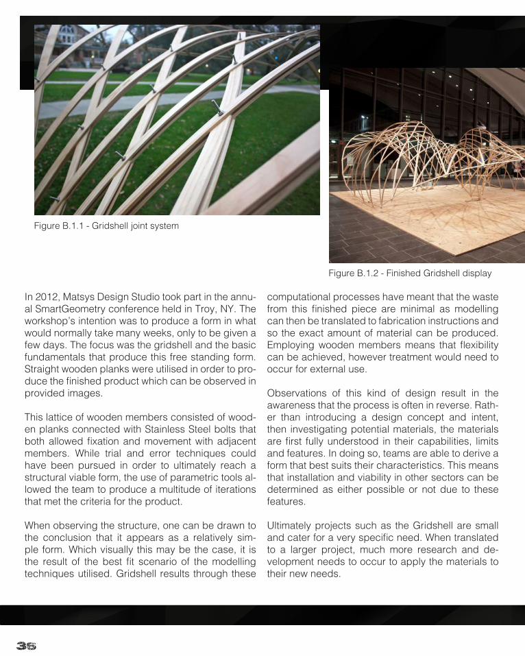
In 2012, Matsys Design Studio took part in the annu-al SmartGeometry conference held in Troy, NY. The workshop’s intention was to produce a form in what would normally take many weeks, only to be given a few days. The focus was the gridshell and the basic fundamentals that produce this free standing form. Straight wooden planks were utilised in order to pro-duce the finished product which can be observed in provided images.
This lattice of wooden members consisted of wood-en planks connected with Stainless Steel bolts that both allowed fixation and movement with adjacent members. While trial and error techniques could have been pursued in order to ultimately reach a structural viable form, the use of parametric tools al-lowed the team to produce a multitude of iterations that met the criteria for the product.
When observing the structure, one can be drawn to the conclusion that it appears as a relatively sim-ple form. Which visually this may be the case, it is the result of the best fit scenario of the modelling techniques utilised. Gridshell results through these
computational processes have meant that the waste from this finished piece are minimal as modelling can then be translated to fabrication instructions and so the exact amount of material can be produced. Employing wooden members means that flexibility can be achieved, however treatment would need to occur for external use.
Observations of this kind of design result in the awareness that the process is often in reverse. Rath-er than introducing a design concept and intent, then investigating potential materials, the materials are first fully understood in their capabilities, limits and features. In doing so, teams are able to derive a form that best suits their characteristics. This means that installation and viability in other sectors can be determined as either possible or not due to these features.
Ultimately projects such as the Gridshell are small and cater for a very specific need. When translated to a larger project, much more research and de-velopment needs to occur to apply the materials to their new needs.
Figure B.1.1 - Gridshell joint system
Figure B.1.2 - Finished Gridshell display

37
PRECEDENT #1
Smart Geometry 2012 Gridshell
Architect: Matsys Design Studio
Location: Troy, NY
Year: 2012
Figure B.1.3 - Gridshell Renders
38
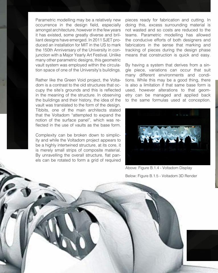
Parametric modelling may be a relatively new occurrence in the design field, especially amongst architecture, however in the few years it has existed, some greatly diverse and bril-liant designs have emerged. In 2011 SJET pro-duced an installation for MIT in the US to mark the 150th Anniversary of the University in con-junction with a Major Yearly Art Festival. Unlike many other parametric designs, this geometric vault system was employed within the circula-tion space of one of the University’s buildings.
Rather like the Green Void project, the Volta-dom is a contrast to the old structures that oc-cupy the site’s grounds and this is reflected in the meaning of the structure. In observing the buildings and their history, the idea of the vault was translated to the form of the design. Tibbits, one of the main architects stated that the Voltadom “attempted to expand the notion of the surface panel”, which was re-flected in the use of vaults as the base form.
Complexity can be broken down to simplic-ity and while the Voltadom project appears to be a highly intertwined structure, at its core, it is merely small strips of composite material. By unravelling the overall structure, flat pan-els can be rotated to form a grid of required
pieces ready for fabrication and cutting. In doing this, excess surrounding material is not wasted and so costs are reduced to the teams. Parametric modelling has allowed the conducive efforts of both designers and fabricators in the sense that marking and tracking of pieces during the design phase means that construction is quick and easy.
By having a system that derives from a sin-gle piece, variations can occur that suit many different environments and condi-tions. While this may be a good thing, there is also a limitation if that same base form is used, however alterations to that geom-etry can be managed and applied back to the same formulas used at conception.
Above: Figure B.1.4 - Voltadom Display
Below: Figure B.1.5 - Voltadom 3D Render

39
PRECEDENT #3
Voltadom pavilion
Architect: SJET - Skylar Tibbits
Location: MIT, Massachusetts, USA
Year: 2011
Figure B.1.8 - Voltadom External Night Display
Below: Figure B.1.7 - Voltadom Internal View - Perspec-
Right: Figure B.1.6 - Voltadom 3D Render
40

41
Case Study 1.0 - Green Void

42
PRECEDENT #2
Green Void Installation
Architect: L.A.V.A
Location: Customs house, Sydney, Australia
Year: 2008
The Green Void installation, located in the Customs house of Sydney’s CBD was a parametric project by the Laboratory for Visionary Architecture in 2008. Also commissioned in Stuttgart, Germany, this piece was the showcase for a regional initia-tive to activate public spaces. The void was de-signed to encapsulate the atrium space of the Cus-tom building which consisted of a space that rose over 20 metres in height and included both closed and open surfaces amongst the various floors.
There is a stark contrast between the existing building and the installation both due to mate-riality and age difference. While the site utilises stone and glass, the Void project employed 40kg of Lycra material that was threaded alongside aluminium tracks and suspended using cabling.
Like other parametric projects, this was the re-sult of the inputs into the modelling software, rather than the culmination of an initial form in-tent. Through placing constraints on the location of the anchor points, the programs were able to create a form that was a best fit for the void.
Figure B.2.1 - Upward View Internal Green Void Figure B.2.2 - Upward View Internal Green Void

43
From a design perspective, it is easy to comprehend the poten-tials resulting from this form. The use of lycra means flexibility and therefore spatial and site con-straints are of less concern than a more rigid structure. Modelling in such a way as to best suit a space also allows the inputs for various other locations to be un-dertaken and so the portability of the project is vast, reflected in its use in Australia and Ger-many. More fluid structures however require bracing and supports in order to be erected. Careful consideration and un-derstanding of the site there-fore must occur to reflect the capacity to hold such a project.
Fabrication concerns are mini-mal because of the flexible na-ture of the material. A single large sheet can create the en-tire structure and cutting pro-duces the finished components ready for assembly. While con-strained to structure, the Green Void is a great example of how parametric modelling systems can make a project work in an unlikely location. Future devel-opment of this technique may see currently discarded and undesirable land revitalised for use by nature and people alike.
Left: Figure B.2.3 - Internal View Green Void Above: Figure B.2.4 - Plans Green Void
44
Series #1
Kangaroo Physics
Architecture Precedent: Green Void
Experiment - Polyline manipulation with kangaroo
Original
Node Size/tube geometry
Node Size/knuckle shape
node geometry/pipe geometry
Change Rest Length/Anchor
rest length/attractor points
input geometry/pipe thickness
rest length/tension/anchor points

45
Series #2
Kangaroo Physics
Architecture Precedent: Green Void
Experiment - Polyline Mesh With Kangaroo (Point charge)
rest length/tension/anchor points
weaverbird Stellate
kangaroo pause simulation
weaverbird frames
Original reflect original/kangaroo
anchor points
node size/kangaroo
weaverbird expand border
46
Series #3
Kangaroo Physics
Architecture Precedent: Green Void
Experiment - mesh geometry with kangaroo simulation
Original - Pipe
Mesh Voronoi
Node Size/Knuckle Thickness
Weaverbird Stellate
weaverbird mesh window
Weaverbird Picture Frame
Weaverbird Facet Dome
Kangaroo Physics

47
Series #4
Kangaroo Physics
Architecture Precedent: Green Void
Experiment - geometry manipulation during simulation
original
kangaroo/anchor points
weaverbird offset
anchor
weaverbird facet dome
kangaroo/point charge
anghor point/rest length
kangaroo/point charge
48
Result Analysis - Selection Criteria
The ultimate aim for this project is to produce a form that responds to the brief but also is creative in its form finding. In selecting highlighted outcomes, variety and potential were considered in the idea of furthering their geometries and advancing their form to work more clos-er towards a final project. Changing iterations explored the multitude of possibilities for a single initial form and provided outcomes that would have potentially been missed through other form finding processes. These four chosen iterations are examples of the experimen-tal processes undertaken on the Green Void script. While aesthetic appeal and interesting structure were considered, potential final outcomes were the main basis for selection as they showed unrealised further results. The products of the Green Void varied greatly from the initial design, yet they still represent the idea of tensile structures. This means that the same con-struction methods can be employed for all the chosen results. By using the script, the effects of the surface geometry were changed, allowing various responses that could potentially be applied to varying projects.
Result 2 is a direct iteration from the base Green Void script. In manipulating existing definitions and adjusting parameters, complex and often unpredictable geometries were produced. This chosen result shows promise for de-velopment due to the dome like structure is incorporates. Anchor points above would mean structural integrity on a real scale and surface patterning shows a Voronoi lattice, meaning joints and construction could be fabricated. The flat nature of the base reflects the potential for this result to be suspended above the ground, allowing circulation space.
Figure B.2.5 - External View Green Void
49
Result Analysis - Selection Criteria
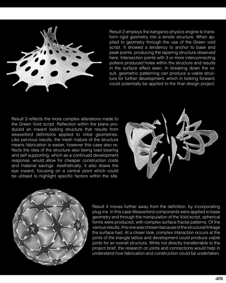
Result 2 employs the kangaroo physics engine to trans-form rigid geometry into a tensile structure. When ap-plied to geometry through the use of the Green void script. It showed a tendency to anchor to base and peak points, producing the tapering structure observed here. Intersection points with 3 or more interconnecting pollens produced holes within the structure and results in the surface effect seen. In breaking down the re-sult, geometric patterning can produce a viable struc-ture for further development, which in looking forward, could potentially be applied to the final design project.
Result 4 moves further away from the definition, by incorporating plug-ins. In this case Weaverbird components were applied to base geometry and through the manipulation of the Void script, spherical forms were produced, with complex surface fractal patterns. Of the various results, this one was chosen because of the structural linkage the surface had. At a closer look, complex interaction occurs at the joints of the triangle lattice and development could produce viable joints for an overall structure. While not directly transferrable to the project brief, the research on joints and connections would help in understand how fabrication and construction could be undertaken.
Result 3 reflects the more complex alterations made to the Green Void script. Reflection within the plane pro-duced an inward looking structure that results from weaverbird definitions applied to initial geometries. Like pervious results, the mesh mature of the structure means fabrication is easier, however this case also re-flects the idea of the structure also being load bearing and self supporting, which as a continued development response, would allow for cheaper construction costs and material savings. Aesthetically, it also draws the eye inward, focusing on a central point which could be utilised to highlight specific factors within the site.
50
Case Study 2.0 - Canton tower
51
Case Study 2.0 - Canton tower
52
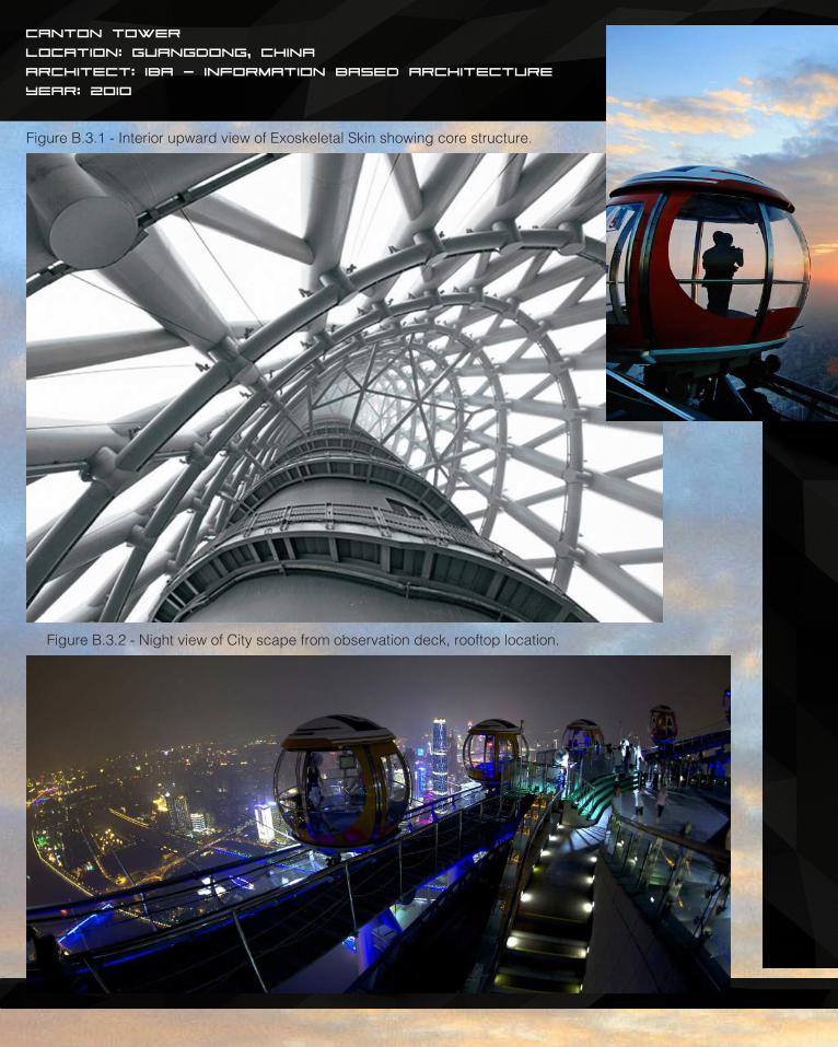
Canton Tower
Location: Guangdong, China
Architect: IBA - Information Based Architecture
Year: 2010
Figure B.3.1 - Interior upward view of Exoskeletal Skin showing core structure.
Figure B.3.2 - Night view of City scape from observation deck, rooftop location.
53
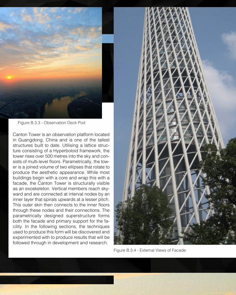
Canton Tower is an observation platform located in Guangdong, China and is one of the tallest structures built to date. Utilising a lattice struc-ture consisting of a Hyperboloid framework, the tower rises over 500 metres into the sky and con-sists of multi-level floors. Parametrically, the tow-er is a joined volume of two ellipses that rotate to produce the aesthetic appearance. While most buildings begin with a core and wrap this with a facade, the Canton Tower is structurally visible as an exoskeleton. Vertical members reach sky-ward and are connected at interval nodes by an inner layer that spirals upwards at a lesser pitch. This outer skin then connects to the inner floors through these nodes and their connections. The parametrically designed superstructure forms both the facade and primary support for the fa-cility. In the following sections, the techniques used to produce this form will be discovered and experimented with to produce results that will be followed through in development and research.
Figure B.3.3 - Observation Deck Pod
Figure B.3.4 - External Views of Facade
54
CURVELOFT
EVALUATE SURFACE
ROTATE (DETERMINED THROUGH EVALSRF)MOVE IN UNIT Z
CURVEROTATE & MOVE OFFSET CURVE DIVIDE CURVE
LINE
OFFSET CURVE DIVIDE CURVE
LINEDIVIDE CURVE EXPRESSION FUNCTION
DIVIDE CURVE EXPRESSION FUNCTIONCURVE
LOFT BOUNDING BOX BOX CORNERS
BREP INTERSECTIONAREA DIVIDE LENGTHROTATE MOVE
FORM
1.
2.
3.
4.
5.
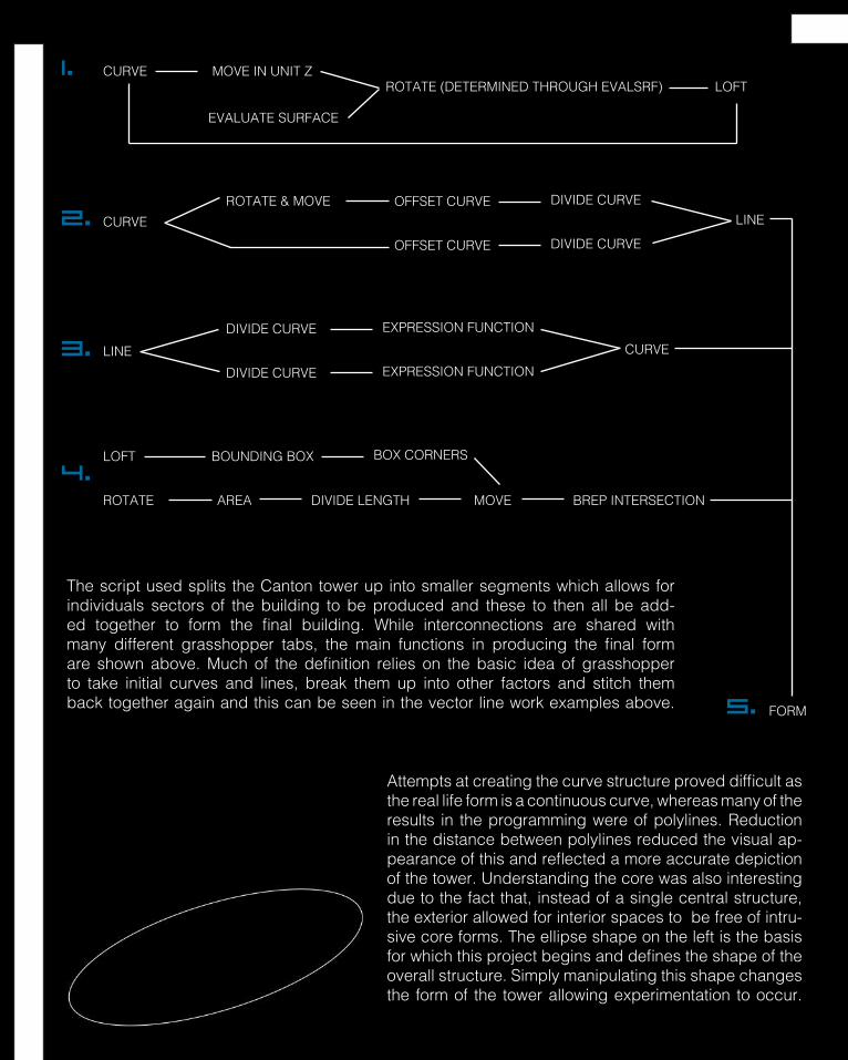
The script used splits the Canton tower up into smaller segments which allows for individuals sectors of the building to be produced and these to then all be add-ed together to form the final building. While interconnections are shared with many different grasshopper tabs, the main functions in producing the final form are shown above. Much of the definition relies on the basic idea of grasshopper to take initial curves and lines, break them up into other factors and stitch them back together again and this can be seen in the vector line work examples above.
Attempts at creating the curve structure proved difficult as the real life form is a continuous curve, whereas many of the results in the programming were of polylines. Reduction in the distance between polylines reduced the visual ap-pearance of this and reflected a more accurate depiction of the tower. Understanding the core was also interesting due to the fact that, instead of a single central structure, the exterior allowed for interior spaces to be free of intru-sive core forms. The ellipse shape on the left is the basis for which this project begins and defines the shape of the overall structure. Simply manipulating this shape changes the form of the tower allowing experimentation to occur.

55
1. 2. 3. 4. 5.
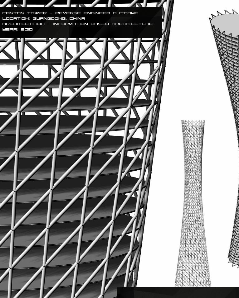
Reverse Engineer Progression
LOFT
LINE
1. Extruded Ellipse surface is lofted with the base Ellipse to form the generic shape of the tower.2. Surface is divided into segmented and lines are drawn through these point to form superstructure.3. Interconnecting members are created by shifting the angle of the curve and creating lines.4. Vertical distance is divided into segments and planes are created to resemble the floors of the tower.5. Superstructure, interconnecting members and the floor system combined form the finished building.
2.
3.
4.
Figure B.3.5 - Interior downward view of Exoskeletal Skin showing core structure.
56
Canton Tower - Reverse Engineer OUtcome
Location: Guangdong, China
Architect: IBA - Information Based Architecture
Year: 2010
57
58
Technique Development
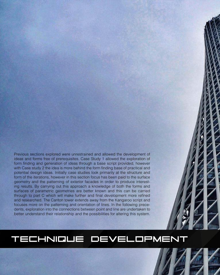
Previous sections explored were unrestrained and allowed the development of ideas and forms free of prerequisites. Case Study 1 allowed the exploration of form finding and generation of ideas through a base script provided, however with Case study 2 the idea is more behind the form finding base of practical and potential design ideas. Initially case studies look primarily at the structure and form of the iterations, however in this section focus has been paid to the surface geometry and the patterning of exterior facades in order to produce interest-ing results. By carrying out this approach a knowledge of both the forms and surfaces of parametric geometries are better known and this can be carried through to part C which will make further and final development more refined and researched. The Canton tower extends away from the Kangaroo script and focuses more on the patterning and orientation of lines. In the following prece-dents, exploration into the connections between point and line are undertaken to better understand their relationship and the possibilities for altering this system.
59
Technique Development
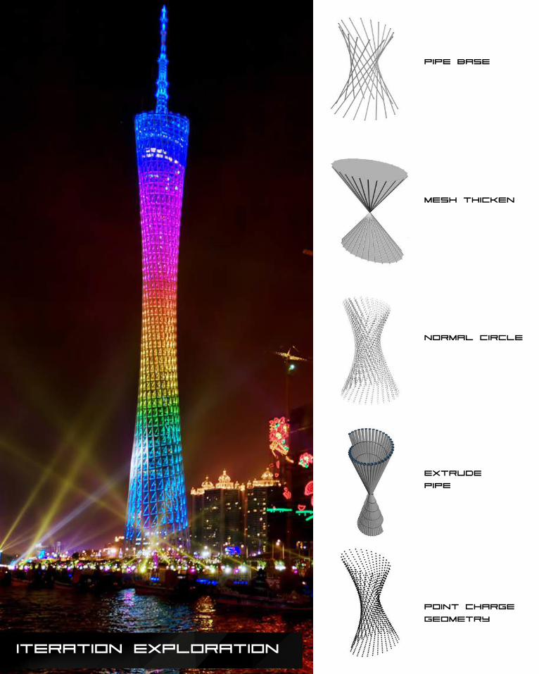
60Iteration Exploration
pipe base
mesh thicken
normal circle
extrude
pipe
point charge
geometry
61
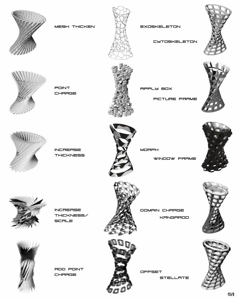
Mesh Thicken
Point
Charge
increase
thickness
increase
thickness/
scale
add point
charge
exoskeleton
apply box
morph
domain charge
offset
cytoskeleton
picture frame
window frame
kangaroo
stellate
62
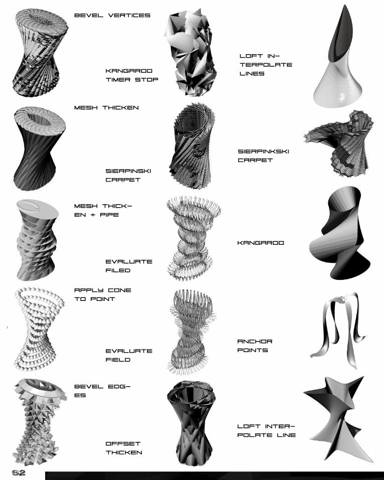
bevel vertices
mesh thicken
mesh thick-
en + pipe
apply cone
to point
bevel edg-
es
kangaroo
timer stop
sierpinski
carpet
evaluate
filed
evaluate
field
offset
thicken
loft in-
terpolate
lines
sierpinkski
carpet
kangaroo
anchor
points
loft inter-
polate line
63
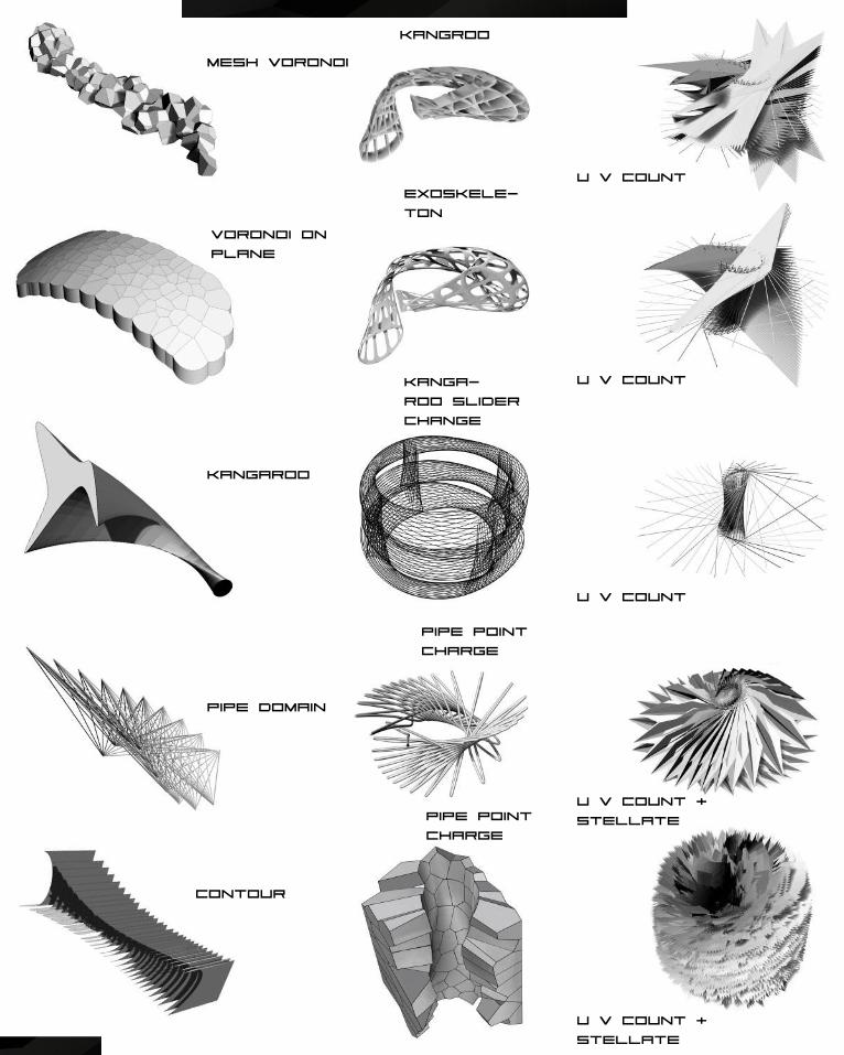
Mesh Voronoi
Voronoi on
plane
kangaroo
pipe domain
contour
kangroo
exoskele-
ton
U V count
U v countkanga-
roo slider
change
U v Count
pipe point
charge
U v count +
stellate
u v count +
stellate
pipe point
charge
64
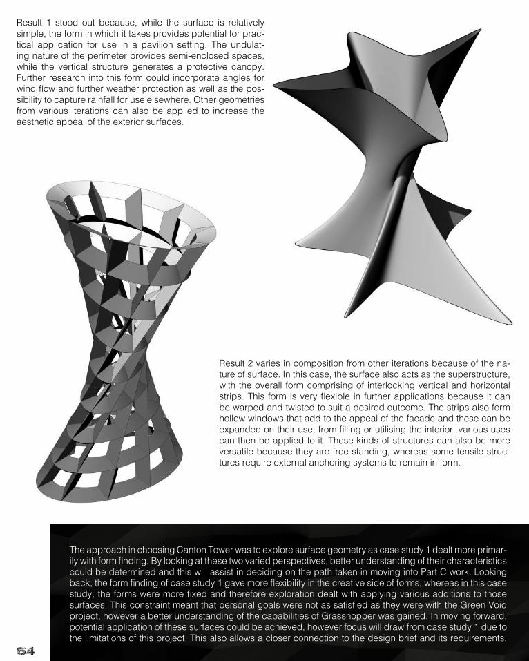
Result 1 stood out because, while the surface is relatively simple, the form in which it takes provides potential for prac-tical application for use in a pavilion setting. The undulat-ing nature of the perimeter provides semi-enclosed spaces, while the vertical structure generates a protective canopy. Further research into this form could incorporate angles for wind flow and further weather protection as well as the pos-sibility to capture rainfall for use elsewhere. Other geometries from various iterations can also be applied to increase the aesthetic appeal of the exterior surfaces.
Result 2 varies in composition from other iterations because of the na-ture of surface. In this case, the surface also acts as the superstructure, with the overall form comprising of interlocking vertical and horizontal strips. This form is very flexible in further applications because it can be warped and twisted to suit a desired outcome. The strips also form hollow windows that add to the appeal of the facade and these can be expanded on their use; from filling or utilising the interior, various uses can then be applied to it. These kinds of structures can also be more versatile because they are free-standing, whereas some tensile struc-tures require external anchoring systems to remain in form.
The approach in choosing Canton Tower was to explore surface geometry as case study 1 dealt more primar-ily with form finding. By looking at these two varied perspectives, better understanding of their characteristics could be determined and this will assist in deciding on the path taken in moving into Part C work. Looking back, the form finding of case study 1 gave more flexibility in the creative side of forms, whereas in this case study, the forms were more fixed and therefore exploration dealt with applying various additions to those surfaces. This constraint meant that personal goals were not as satisfied as they were with the Green Void project, however a better understanding of the capabilities of Grasshopper was gained. In moving forward, potential application of these surfaces could be achieved, however focus will draw from case study 1 due to the limitations of this project. This also allows a closer connection to the design brief and its requirements.
65
Result Analysis - Selection Criteria
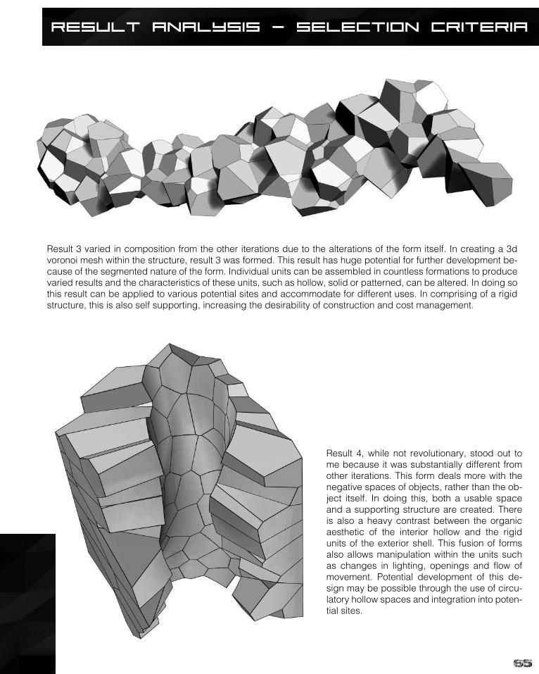
Result 3 varied in composition from the other iterations due to the alterations of the form itself. In creating a 3d voronoi mesh within the structure, result 3 was formed. This result has huge potential for further development be-cause of the segmented nature of the form. Individual units can be assembled in countless formations to produce varied results and the characteristics of these units, such as hollow, solid or patterned, can be altered. In doing so this result can be applied to various potential sites and accommodate for different uses. In comprising of a rigid structure, this is also self supporting, increasing the desirability of construction and cost management.
Result 4, while not revolutionary, stood out to me because it was substantially different from other iterations. This form deals more with the negative spaces of objects, rather than the ob-ject itself. In doing this, both a usable space and a supporting structure are created. There is also a heavy contrast between the organic aesthetic of the interior hollow and the rigid units of the exterior shell. This fusion of forms also allows manipulation within the units such as changes in lighting, openings and flow of movement. Potential development of this de-sign may be possible through the use of circu-latory hollow spaces and integration into poten-tial sites.
66
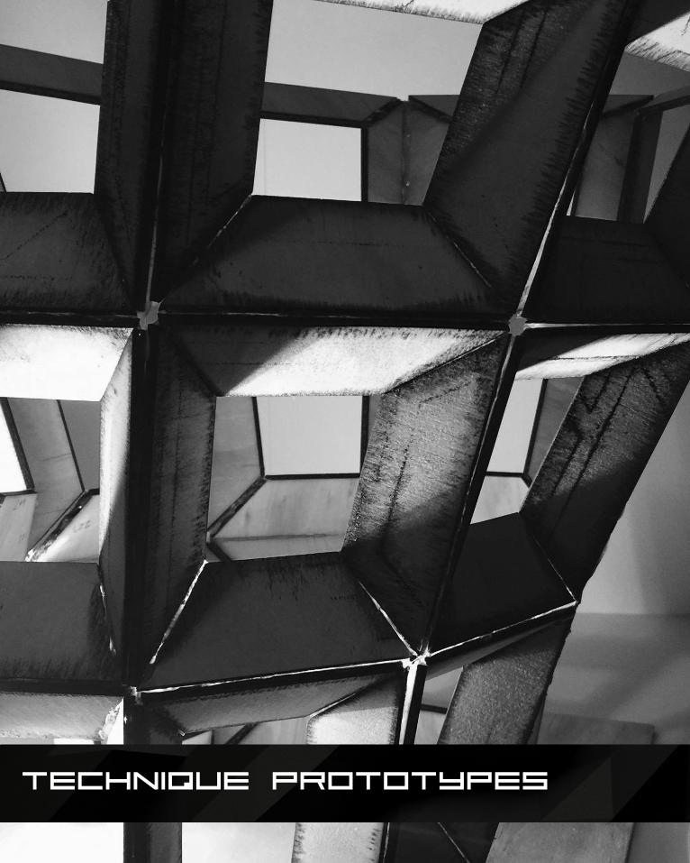
Technique Prototypes
67
Technique Prototypes
68
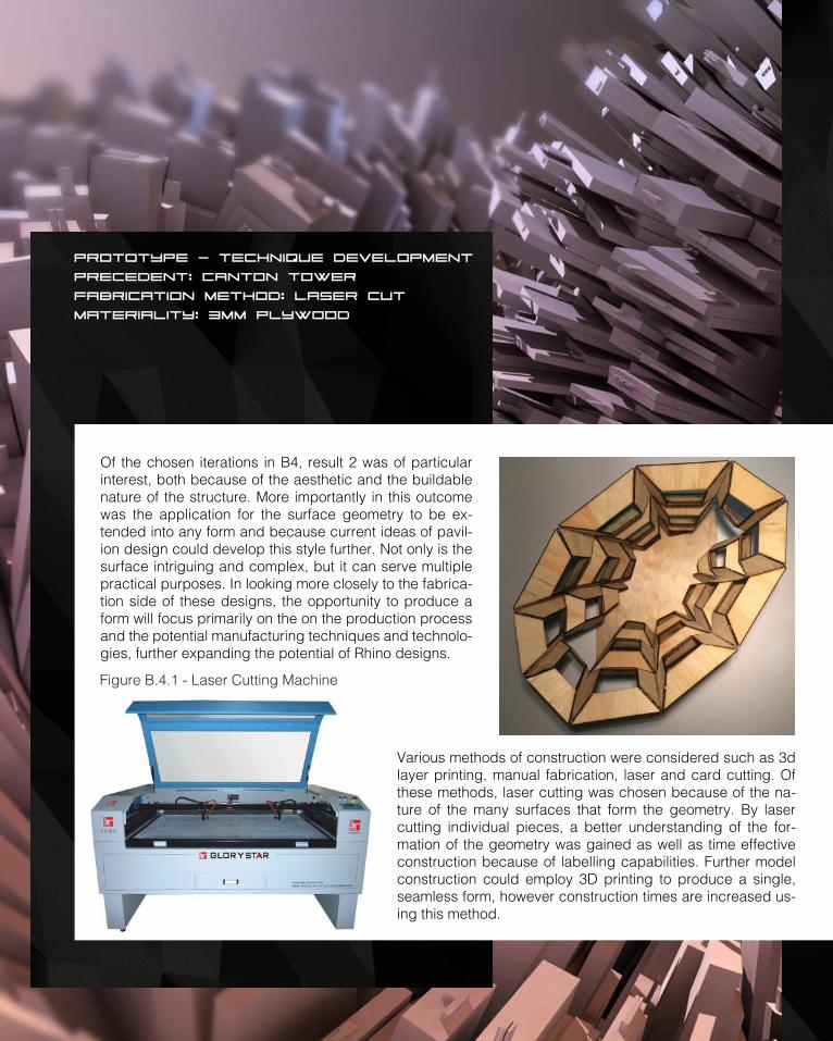
Various methods of construction were considered such as 3d layer printing, manual fabrication, laser and card cutting. Of these methods, laser cutting was chosen because of the na-ture of the many surfaces that form the geometry. By laser cutting individual pieces, a better understanding of the for-mation of the geometry was gained as well as time effective construction because of labelling capabilities. Further model construction could employ 3D printing to produce a single, seamless form, however construction times are increased us-ing this method.
Of the chosen iterations in B4, result 2 was of particular interest, both because of the aesthetic and the buildable nature of the structure. More importantly in this outcome was the application for the surface geometry to be ex-tended into any form and because current ideas of pavil-ion design could develop this style further. Not only is the surface intriguing and complex, but it can serve multiple practical purposes. In looking more closely to the fabrica-tion side of these designs, the opportunity to produce a form will focus primarily on the on the production process and the potential manufacturing techniques and technolo-gies, further expanding the potential of Rhino designs.
Prototype - technique development
Precedent: canton tower
Fabrication method: Laser cut
materiality: 3mm plywood
Figure B.4.1 - Laser Cutting Machine
69
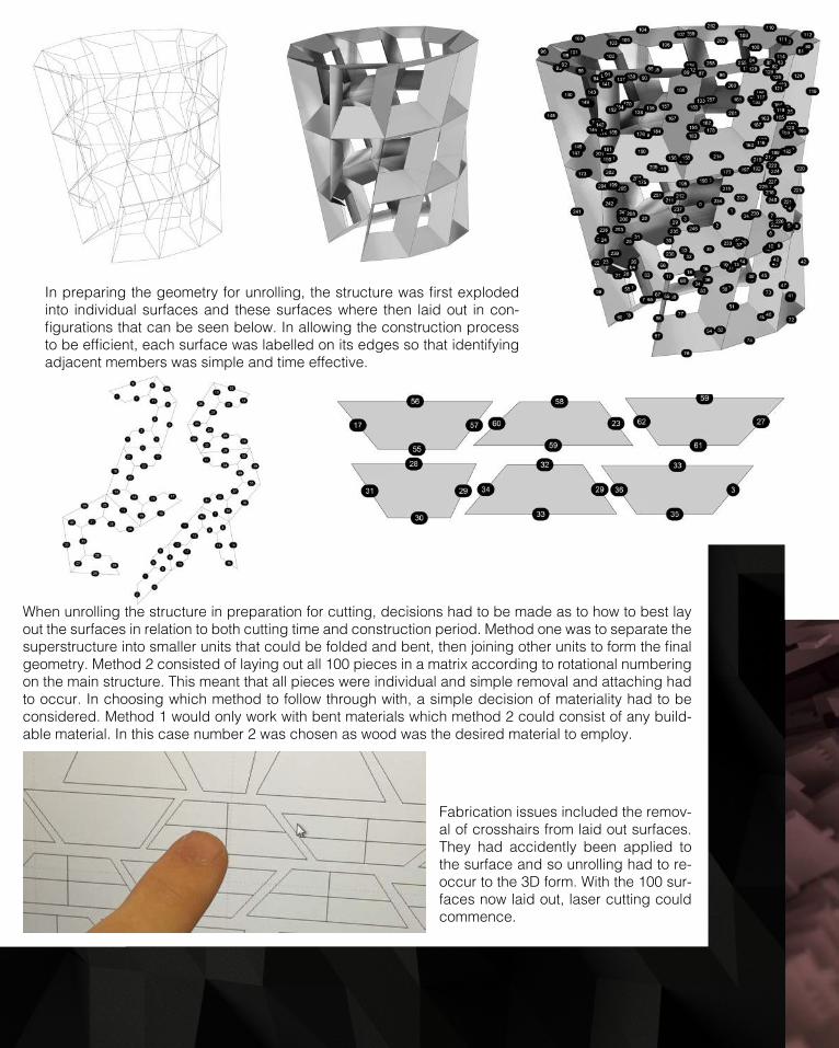
In preparing the geometry for unrolling, the structure was first exploded into individual surfaces and these surfaces where then laid out in con-figurations that can be seen below. In allowing the construction process to be efficient, each surface was labelled on its edges so that identifying adjacent members was simple and time effective.
When unrolling the structure in preparation for cutting, decisions had to be made as to how to best lay out the surfaces in relation to both cutting time and construction period. Method one was to separate the superstructure into smaller units that could be folded and bent, then joining other units to form the final geometry. Method 2 consisted of laying out all 100 pieces in a matrix according to rotational numbering on the main structure. This meant that all pieces were individual and simple removal and attaching had to occur. In choosing which method to follow through with, a simple decision of materiality had to be considered. Method 1 would only work with bent materials which method 2 could consist of any build-able material. In this case number 2 was chosen as wood was the desired material to employ.
Fabrication issues included the remov-al of crosshairs from laid out surfaces. They had accidently been applied to the surface and so unrolling had to re-occur to the 3D form. With the 100 sur-faces now laid out, laser cutting could commence.
Prototype - technique development
Precedent: canton tower
Fabrication method: Laser cut
materiality: 3mm plywood

70
Once ready for fabrication, required files were sent for cutting, various testing was carried out on the sur-face to analysis the thickness and strength that was required for the laser to accurately cut the wooden plane. Once cut, units of 4 tiles were joined to forms windows which would ultimately result in the final ge-ometry.
as
The final model was tested with various forces and fac-tors such as light which can be observed on the right. In testing for light, an understanding of how spaces would feel during certain times of the day could then be applied to shading systems and openings. In doing so the build-ing would better be understood in developing further.
25 window units were generated which then would be applied to the final form. In achieved a more accurate result, sets of three windows were joined to form vertical columns. With 6 sets of vertical columns and additional floating columns, the final form took shape.

71
While construction methods involved the use of window units to form the final geometry, real world application would see vertical and horizontal strips interlocking with each other. In doing so a joint system would allow structural integrity but also because of the nature of the joints, they would in turn be concealed within the banded structure, providing a seam-less aesthetic from the external and internal areas. Another method for joining would be to have brackets attaching each window bay to adjacent bays, however this would mean sealing and gaps would be form and be required to manage.
72
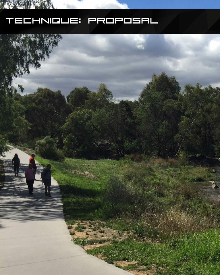
Technique: Proposal
73
Technique: Proposal
74
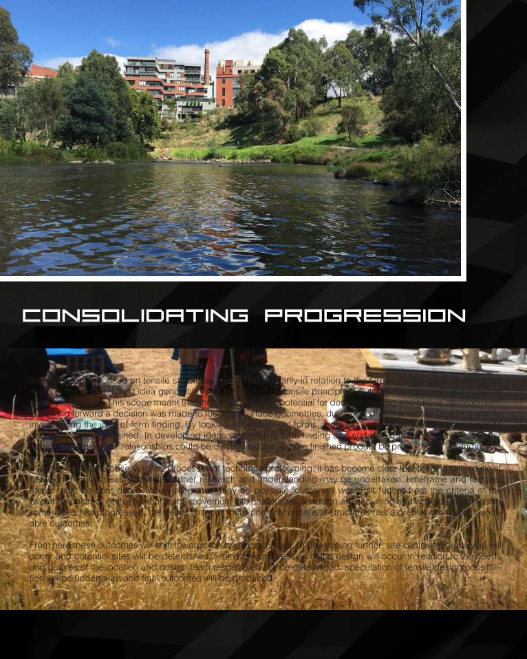
consolidating progression
Initial concepts focused on tensile structures and forms, primarily in relation to the Green Void project. In doing so, much of the research and idea generation was formulated on tensile principles. Outcomes produced were versatile and varied in form. This scope meant that there was a greater potential for decision making and further development. In moving forward a decision was made to focus on surface geometries, due to the previous tensile research mainly investigating the idea of form finding. By looking into more rigid forms, a greater knowledge of their characteristics and principles was gained. In developing ideas surrounding form finding and surfaces, the hope was that a better understanding of their relationships could be discovered and a more finished product be produced as an end result.
In transitioning and observing the processes of technique prototyping, it has become clear that there is still a disjoint between the two areas and while further research and understanding may be undertaken, timeframe and require-ments must be considered. While integration may be possible, outcomes would sit further from the criteria of the brief than desired. At this current point, movement into final stages of design are occurring and while development of some ideas has progressed, the desire to focus more primarily on tensile structures has a greater chance of favour-able outcomes.
From here these outcomes will shift towards the brief and the site. In developing further, site context and analysis will occur and potential sites will be determined. From here progression of the design will occur in relation to the needs and desires of the location and design team respectively. Once determined, speculation of tensile design possibili-ties will be undertaken and final outcomes will be produced.
75
76
77
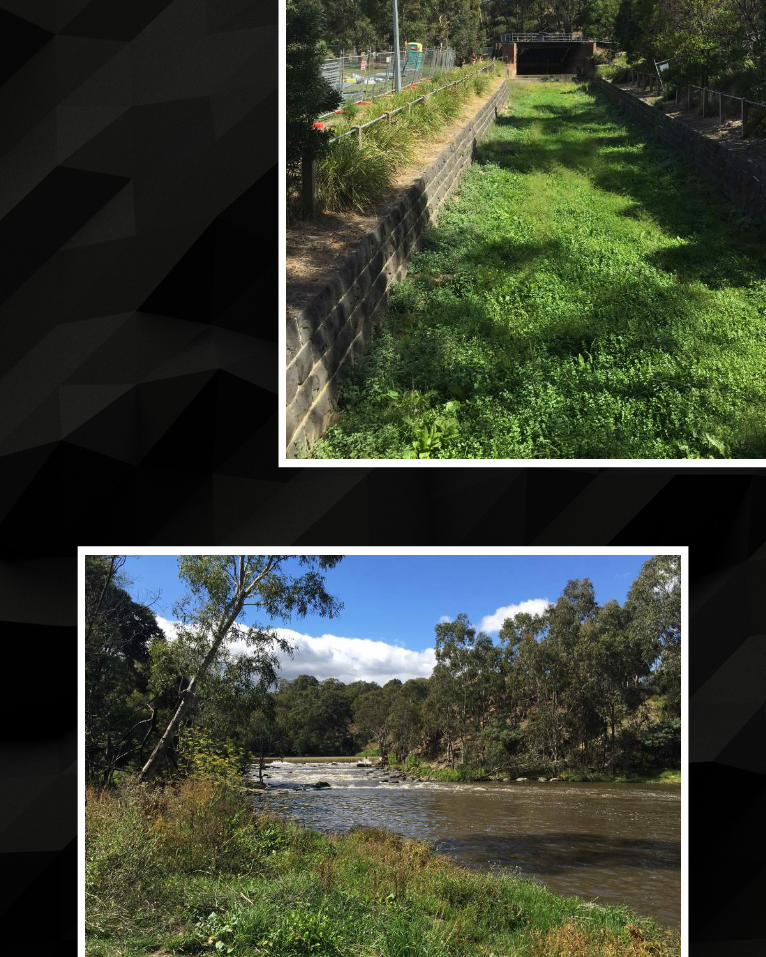
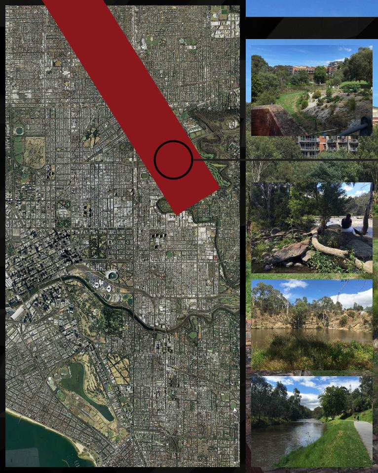
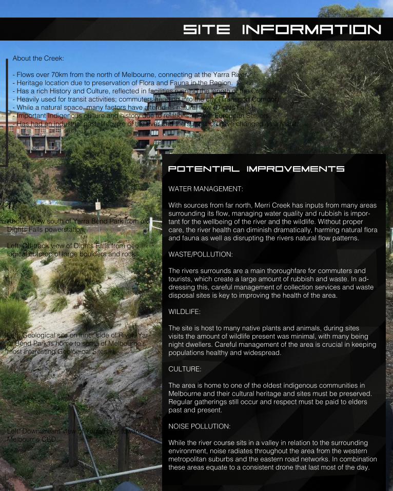
About the Creek:
- Flows over 70km from the north of Melbourne, connecting at the Yarra River.- Heritage location due to preservation of Flora and Fauna in the Region.- Has a rich History and Culture, reflected in facilities running the length of the Creek.- Heavily used for transit activities; commuters heading into the city (Transport Corridor).- While a natural space, many factors have altered its natural flow (Dights Falls).- Important Indigenous culture and history due to relationship with European Settlers.- Has had an industrial past, lifecycle of the river and the surrounds have changed as a result.
site information
WATER MANAGEMENT:
With sources from far north, Merri Creek has inputs from many areas surrounding its flow, managing water quality and rubbish is impor-tant for the wellbeing of the river and the wildlife. Without proper care, the river health can diminish dramatically, harming natural flora and fauna as well as disrupting the rivers natural flow patterns.
WASTE/POLLUTION:
The rivers surrounds are a main thoroughfare for commuters and tourists, which create a large amount of rubbish and waste. In ad-dressing this, careful management of collection services and waste disposal sites is key to improving the health of the area.
WILDLIFE:
The site is host to many native plants and animals, during sites visits the amount of wildlife present was minimal, with many being night dwellers. Careful management of the area is crucial in keeping populations healthy and widespread.
CULTURE:
The area is home to one of the oldest indigenous communities in Melbourne and their cultural heritage and sites must be preserved. Regular gatherings still occur and respect must be paid to elders past and present.
NOISE POLLUTION:
While the river course sits in a valley in relation to the surrounding environment, noise radiates throughout the area from the western metropolitan suburbs and the eastern road networks. In combination these areas equate to a consistent drone that last most of the day.
potential improvements
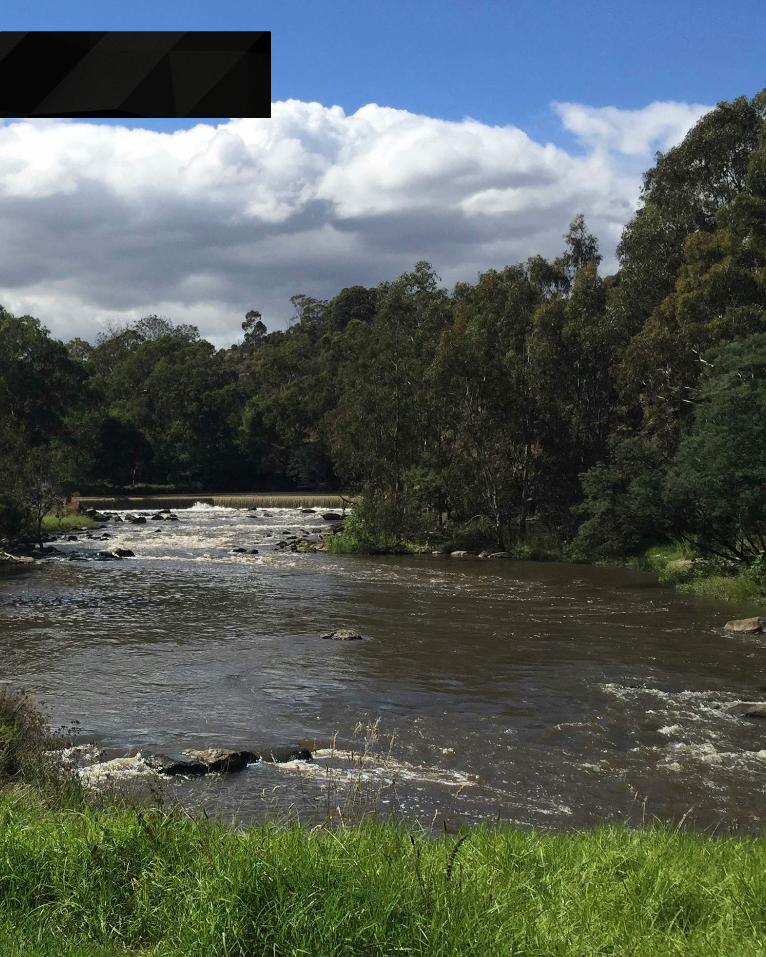
Above: View south of Yarra Bend Park from old Dights Falls powerstation.
Left: Off-track view of Dights Falls from geo logical outcrop of large boulders and rocks.
Left: Geological site on inner side of River. Yar-ra Bend Park is home to some of Melbourne’s most interesting Geological Sites.
Left: Downstream view of Yarra River towards Melbourne CBD.
78
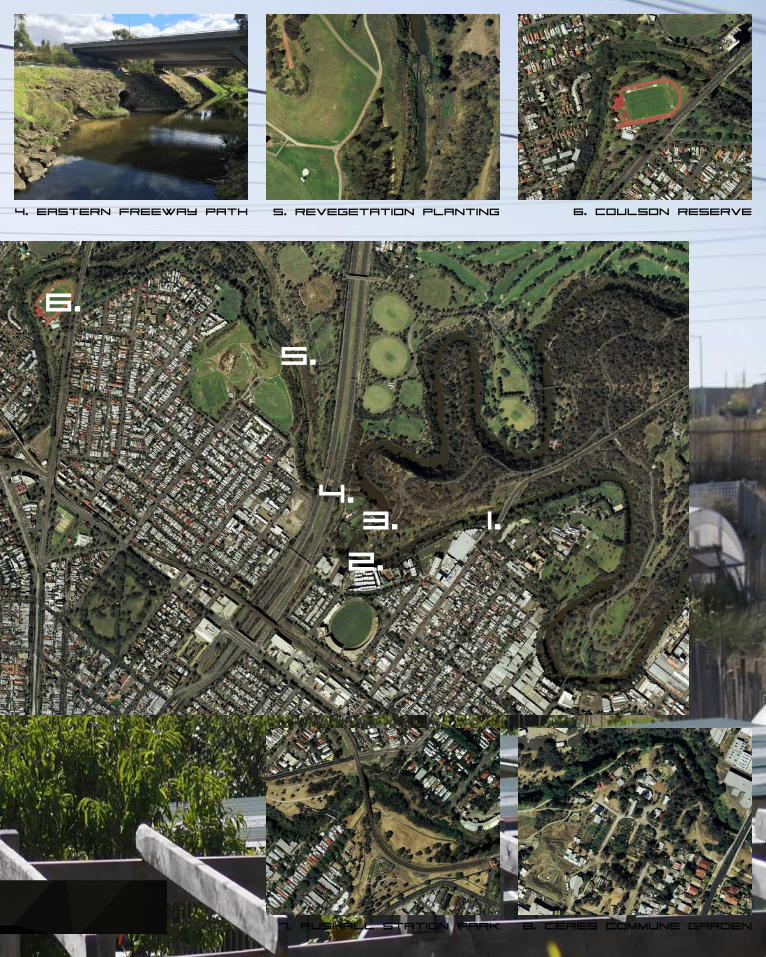
site visit - Merri Creek
8.
1. Yarra bend park walk 2. Dights Falls Approach 3. Falls/hydroplant
A site visit was carried out early in the deign period as it meant exploration of the region would be undertaken without bias or seeking particular features. It allowed areas to draw our attention both because of their natural and aesthetic appeal and their potential need to improvement. The site is home to both human and animal inhabitants and crosses some of Mel-bourne’s innermost suburbs. While in some areas there is a disconnect between the surrounding environment and the river course, other locations embrace the creek and offer both recreational and viewing facilities. It was interesting to note the varying river features, while some rivers only have gentle flow, the Merri Creek featured characteristics such as small rapids, rocky outcrops, meandering canals and larger gentle, open flows. All these add to both beauty and appeal of the region.
7.
Figure B.6.1 - Map of Merri Creek Region
79
1.
2.
3.4.
5.
4. Eastern freeway path 5. revegetation planting 6. coulson reserve
7. Rushall Station Park 8. Ceres Commune Garden
6.
80
1. 2.
3. 4.
5. 6.
81
Site Usage - Merri Creek
The Merri Creek System is a relatively long stretch of river with changing surrounds throughout. The site hosts various centres, facilities and recreational parks along the way and while these may attract the gathering of people, the majority of the creek is filled with passing human traffic. In visiting the site multiple times, it became clear that a large portion of the trail consist of commuting traffic to and from inner-city regions and the CBD. The large pathway systems allow both foot and bike traffic and are ideal for physical exercise or simply strolling to enjoy the natural environment. Areas such as Ceres Environmental Park and the Dights Falls region offer a space to stop and unwind and here you will find a concentrated amount of human presence.
With much of the site being continually upgraded and revitalised, sites such as dights falls hold a key historical and cultural footprint. Once residing here was the Dights Falls powerplant which supplied power to local industry and the site present today still pays homage to that era with the new facility incorporating the old structure. Indigenous communities also share a strong link to this sacred land and regular gatherings and ceremonies occur on these lands in respect to tradition and ways of life.
From observing the movements of people throughout the length of Merri Creek, it has become clear that more spaces are required to slow the relentless flow of transition-ing traffic. The site boasts some incredible flora and fauna and the landscapes are beautiful. While many observe this in passing, stopping and appreciating it creates a greatly improved experience. Potential design development will seek to provide a space that both slows this rapid movement but allows the ability to enjoy and absorb the surrounding environment and all it has to offer.
1. Merri Creek Trail during site visit - Human usage is high during normal peak periods, however quiet in low periods.2. Dights Falls looking out from northern banks - Access has been limited due to improvements being made on water system.3. Original Power Station located at Dights Falls - Now remains as a cultural and heritage site for visitors - access limited.4. Site visit revealed that many off site locations have open drains flowing into the Yarra/Merri Creek system - Intense smell.5. The sites pathways and trails hold tourists, local residents and city commuters - High volumes of foot traffic.6. Due to lack of regulation and management, large areas of lesser stream flow are filled with rubbish deposits and waste.
82
Site - ceres environmental park
1.
2.
3.
5.
Observation of the site has revealed 5 potential sites to base a development on:
1. Main entrance space in front of visitor centre - Has consistent human activity both passing and active.
2. Northern Merri Creek Trail Entrance - This intersection of pathes creates a northern entrance into the centre and is currently under utilised.
3. Centre access intersection - This space sits at the crossroads of the centre and could act as a hub for both Ceres and the Merri Creek trail - Involv-ing both parties.
4. Eastern River Trail - The eastern end of the centre meets the Merri Creek Trail and this site would be ideal in acting as an in between space between Ceres and people using the trails and local facilities.
5. Outdoor Meeting Circle - Located in the southern part of the centre lies an open circular space with central fire space. Potential increase in this sites fa-cilities could see more usage of the area.
In relating to the brief and also the context of the site, a variety of potential design options could be developed for a final outcome:
- Central Gathering Pavilion- Water Management/Capture System- Greenhouse Facility- Central Hub Facility Extension- Integration River/Hub Pavilion- Cultural/Historical Information Hub
83
Site - ceres environmental park
4.
Ceres Environmental Park is a community based organisation that deals with environmental education and aware-ness through both learning and practical application. Located in East Brunswick, the large, open site is host to various facilities including gardens, farms, markets and shops.
By placing an importance on the community and by having an open relationship with local regions, the centre has fundamentally improved the understanding of people who enters its gates. In achieving goals, the centre has stood by a set of core principles:
- Address the causes of climate change.
- Promote social wellbeing and connectedness.
- Build local and global equity.
- Embrace and facilitate rapid change.
The aim of further development is to pursue a design project that sits in unison with these principles and endeav-ors to improve on what already is a crucial centre in the region.

84
Implementation of a catchment system for use within site facilities - A sustainable approach to site conservation.
Further analysis of the site made clear the amount of natural processes that are occurring within the centre, from farms, gardens and research facilities. While it is relatively straightfor-ward to construct a simple pavilion, the challenge here is to provide a structure that pushes the boundaries of what a pavilion can do. In linking both form and function, the idea is to provide the centre with a water catchment system which will feed water supply back into the site while providing an area where people can meet and spend time. The benefits are simple yet effective:
- Sustainable- Environmentally Friendly- Cost Effective- Education and Awareness- Community Engagement- Multiple Uses
In finalising the style of pavilion and its requirements, a suitable site had to be chosen. Initial analysis of 5 potential zones was determined during visits as suitable for both connecting the centre and developing a under appreciated site. Of these 5, the southern ceremonial circle area was chosen as the primary location. This is both due to the proximity to one of the centres main thoroughfares as well as the central position in relation to the community gardens, learning centre and eco house. More importantly, this site is in close connection the sites dam which would act as the dumping ground for water collected through the designed pavilion. In keeping the design close to water sources, costs are reduced in running lengthy drain systems around the centre.
Lee Street
chosen site - Ceres meeting space
85
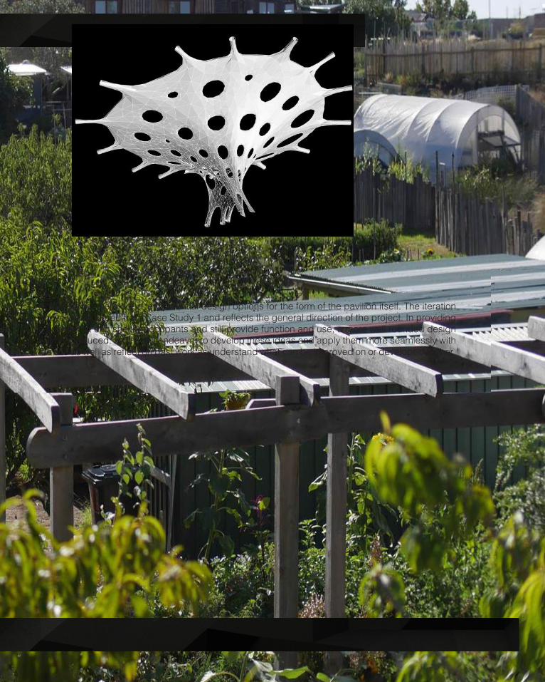
At this stage, there are a few potential design options for the form of the pavilion itself. The iteration above was sourced from Case Study 1 and reflects the general direction of the project. In providing a space that can shelter occupants and still provide function and use, a more well rounded design will be produced. Part C will endeavor to develop these ideas and apply them more seamlessly with the site as well as reflect on past work as understand what can be improved on or developed further.

86
interim submission feedback
Interim presentations were carried out prior to submission in order to receive feed-back from an external source. By having a panel of neutral parties an unbiased dis-cussion could occur in order to establish what works and what needs further devel-opment and improvement.
Comments were made regarding the disconnect between the forms in Case Study 1 and those in Case Study 2. As previously mentioned, research in the first study was undertaken to further understand form finding as a process of Grasshopper while studies in number 2 were primarily focused on surface geometries and how they can influence both the aesthetic and the appearance of a finished design. With com-ments made it became clear that this was both a positive and a negative. In doing so a more well-rounded understanding was formed, however there was less continual development from early stages to now.
Reference was also made in regards to prototypes and the future direction of the project. Initial development was focused on ultimately producing a rigid structure. With the advent of shifting from individual work to group work, a decision was made to transition to a tensile structure and so work in rigid structures became useful but no longer a pursuit for an end result. This in turn meant that development of a prototype reflected that work to date but a new direction be taken into Part C.
Overall feedback was positive, however discussion occurred in relation to the amount of research and development compared to focused refinement. Entering this subject was met with a lack of experience with Grasshopper and so, like many other mem-bers of the subject, substantial time has been spent in learning and utilising the Grasshopper software. In doing so many potential designs have been produced in accordance with the needs of Case Study 1 and 2. Up until this stage, much of the design had been focused on exploration but in agreement with comments made by the panel, focused refinement must now occur with the most promising designs in order to produce what will hopefully be a fully realised end result.

87

88

89
PART C.
detailed design

90
Analysing Progress

91
Discussion with staff and designers suggests the direction in which this project must take. Collection an refinement of our direction as a group has resulted in a more clear path forward and it is apparent that a lack of connection in regards to the new con-cept is present. In moving forward, a decision has to be made on the final course of the design process and a thorough progression of development. With a better under-standing of digital tools and the advantage of now 4 team members, finalisation of a finished product is within reach. The next stage is to begin developing the design to a more practical and applicable piece that both agrees with the research undertaken to this point, as well as agree with the new team direction. Integration of the design must also be better suited to the site and its context, rather than simply being situ-ated in a location unrelated to the design intent. In working with such a versatile and dynamic principle, the idea of form-finding will also have to shift to the real-life appli-cations of such a design, primarily in regards to its construction and implementation.
Further development and research must therefore occur in regards to the construc-tion and assembly aspects of the design to accommodate for budget, timeframe, materials and transport. In doing so a better understanding will be gained as to the real world processes in manufacturing and construction. Due to the nature of the design intent a construction method will have to be established that responds to the minimal timeframe in which we have to deliver the finished form. This will both affect the aspects like materials and the fabrication technologies used.
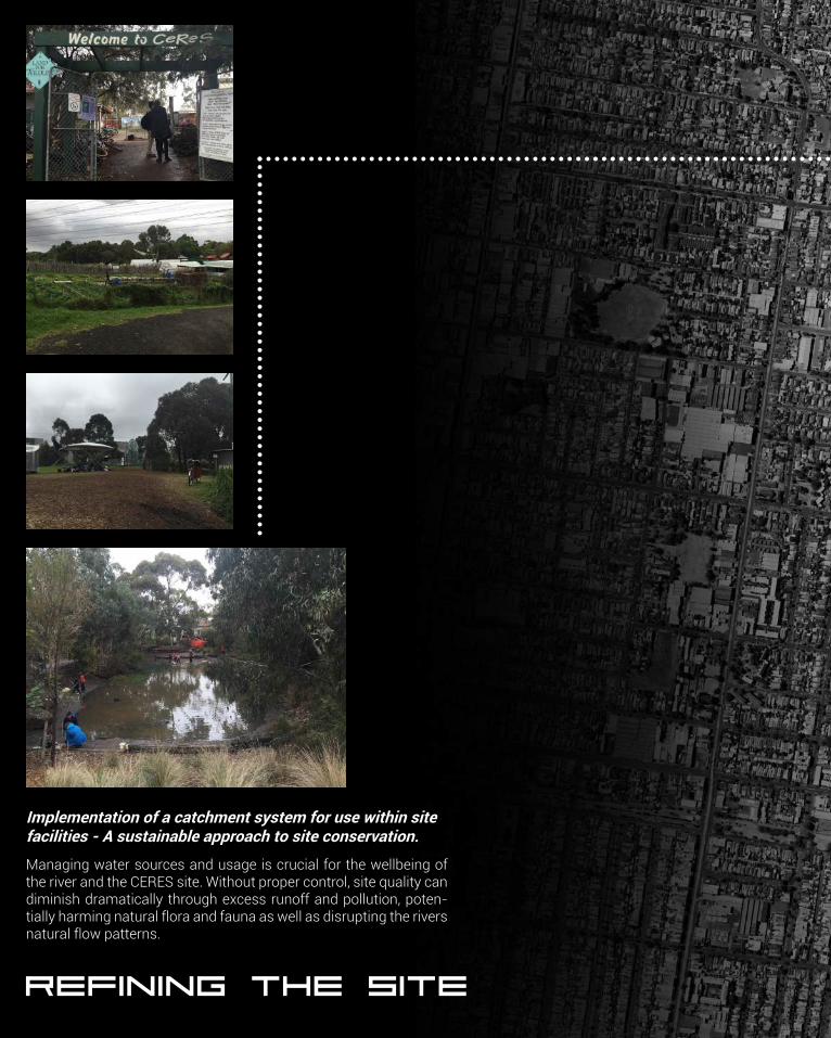
92
refining the site
Managing water sources and usage is crucial for the wellbeing of the river and the CERES site. Without proper control, site quality can diminish dramatically through excess runoff and pollution, poten-tially harming natural flora and fauna as well as disrupting the rivers natural flow patterns.
Implementation of a catchment system for use within site facilities - A sustainable approach to site conservation.
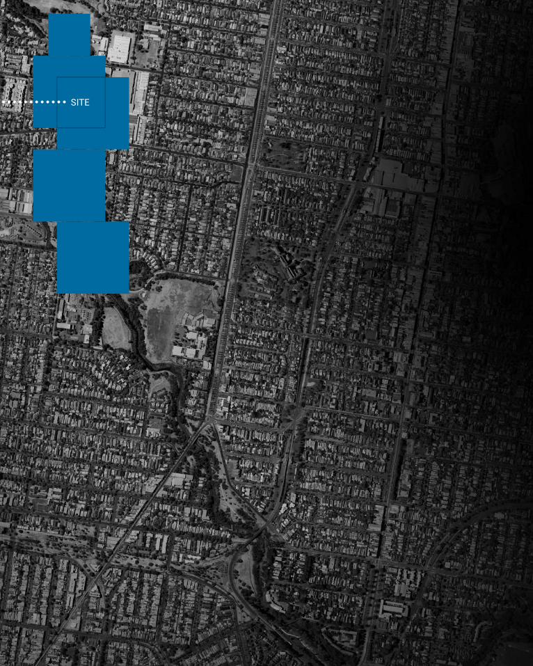
93
SITE
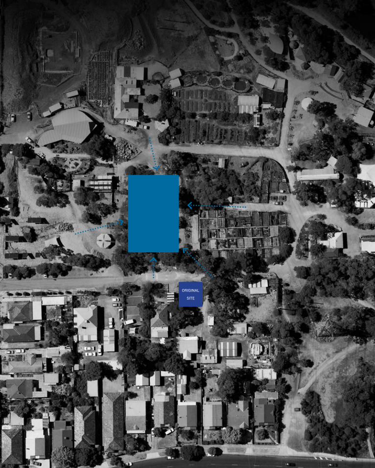
94
DEVELOPED SITE
ORIGINAL
SITE
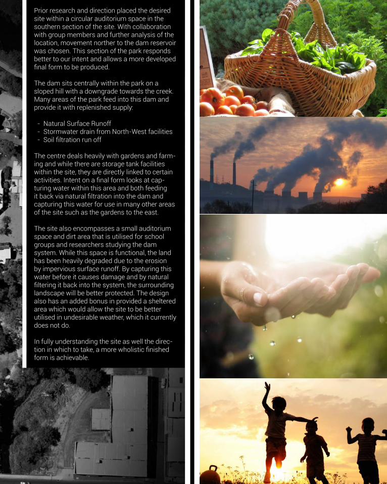
95
Prior research and direction placed the desired site within a circular auditorium space in the southern section of the site. With collaboration with group members and further analysis of the location, movement norther to the dam reservoir was chosen. This section of the park responds better to our intent and allows a more developed final form to be produced.
The dam sits centrally within the park on a sloped hill with a downgrade towards the creek. Many areas of the park feed into this dam and provide it with replenished supply:
- Natural Surface Runoff - Stormwater drain from North-West facilities - Soil filtration run off
The centre deals heavily with gardens and farm-ing and while there are storage tank facilities within the site, they are directly linked to certain activities. Intent on a final form looks at cap-turing water within this area and both feeding it back via natural filtration into the dam and capturing this water for use in many other areas of the site such as the gardens to the east.
The site also encompasses a small auditorium space and dirt area that is utilised for school groups and researchers studying the dam system. While this space is functional, the land has been heavily degraded due to the erosion by impervious surface runoff. By capturing this water before it causes damage and by natural filtering it back into the system, the surrounding landscape will be better protected. The design also has an added bonus in provided a sheltered area which would allow the site to be better utilised in undesirable weather, which it currently does not do.
In fully understanding the site as well the direc-tion in which to take, a more wholistic finished form is achievable.
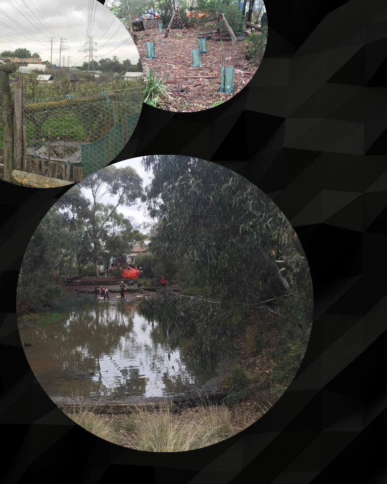
96
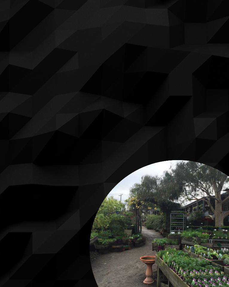
97

98
395 Gigalitres of freshwater supplied to Greater Melbourne region each year
254 GL 99GL 42GLResidential Usage Non-Residential Usage Lost Water/ Emergencies
While much of this water is collected as rainfall in catchments and distributed to Melbourne, a large portion of this water ends up in stormwater and drainage systems, ultimately ending up in Port Phillip Bay and the ocean. Better management of these systems would allow the reuse and recycling of water, leading to a more sustainable water practice in the metropolitan area.
Melbourne
Potable Mains Water
Stormwater
Infiltration
Rainwater
WastewaterEvapotranspiration
HOBART
MELBOURNE
CANBERRA
SYDNEY
BRISBANE
DARWIN
ADELAIDE
PERTH
602.6mm
568.7mm
632.6mm
1213.4mm
1025.4mm
1732.4mm
546.3mm
728.6mm
Australia has a rich diversity in landscapes and this has resulted in a variety of different climates. In par-ticular, Melbourne experiences dramatic seasonal variation throughout the year. Because of its location, rainfall occurs in an irregular manner and has some of the lowest average rainfall per year. With recent drought periods and the shift to sustainable living, the utilisation of water and its management have be-come key factors in daily living, both at a the public and governmental levels.
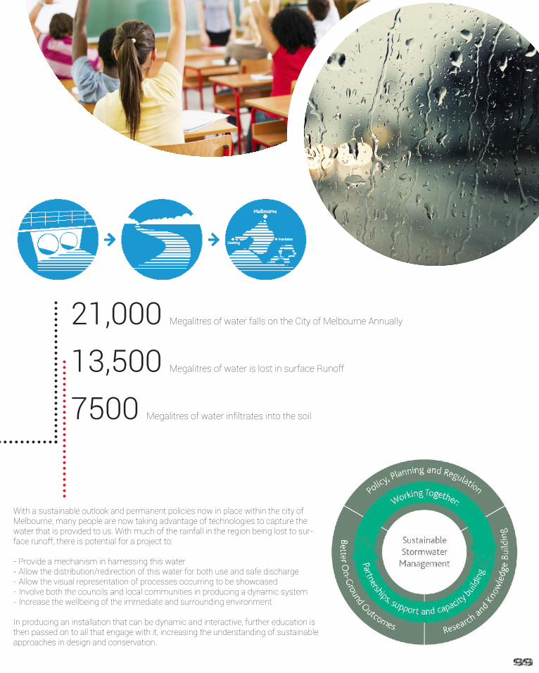
99
21,000 Megalitres of water falls on the City of Melbourne Annually
InfiltrationWastewater
7500 Megalitres of water infiltrates into the soil
13,500 Megalitres of water is lost in surface Runoff
With a sustainable outlook and permanent policies now in place within the city of Melbourne, many people are now taking advantage of technologies to capture the water that is provided to us. With much of the rainfall in the region being lost to sur-face runoff, there is potential for a project to:
- Provide a mechanism in harnessing this water- Allow the distribution/redirection of this water for both use and safe discharge- Allow the visual representation of processes occurring to be showcased- Involve both the councils and local communities in producing a dynamic system- Increase the wellbeing of the immediate and surrounding environment
In producing an installation that can be dynamic and interactive, further education is then passed on to all that engage with it, increasing the understanding of sustainable approaches in design and conservation.
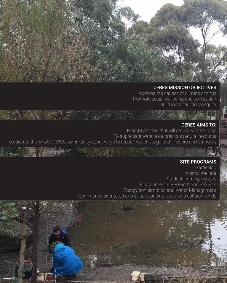
100
CERES MISSION OBJECTIVESAddress the causes of climate change
Promote social wellbeing and connectionBuild local and global equity
CERES AIMS TO:Prompt actions that will reduce water usage
To appreciate water as a precious natural resourceTo educate the whole CERES community about ways to reduce water usage both indoors and outdoors
SITE PROGRAMSGardening
Animal WelfareStudent learning classes
Environmental Research and ProjectsEnergy conusmption and Water Management
Community orientated events surrounding social and cultural trends
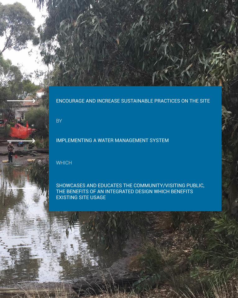
101
ENCOURAGE AND INCREASE SUSTAINABLE PRACTICES ON THE SITE
SHOWCASES AND EDUCATES THE COMMUNITY/VISITING PUBLIC, THE BENEFITS OF AN INTEGRATED DESIGN WHICH BENEFITS EXISTING SITE USAGE
WHICH
IMPLEMENTING A WATER MANAGEMENT SYSTEM
BY
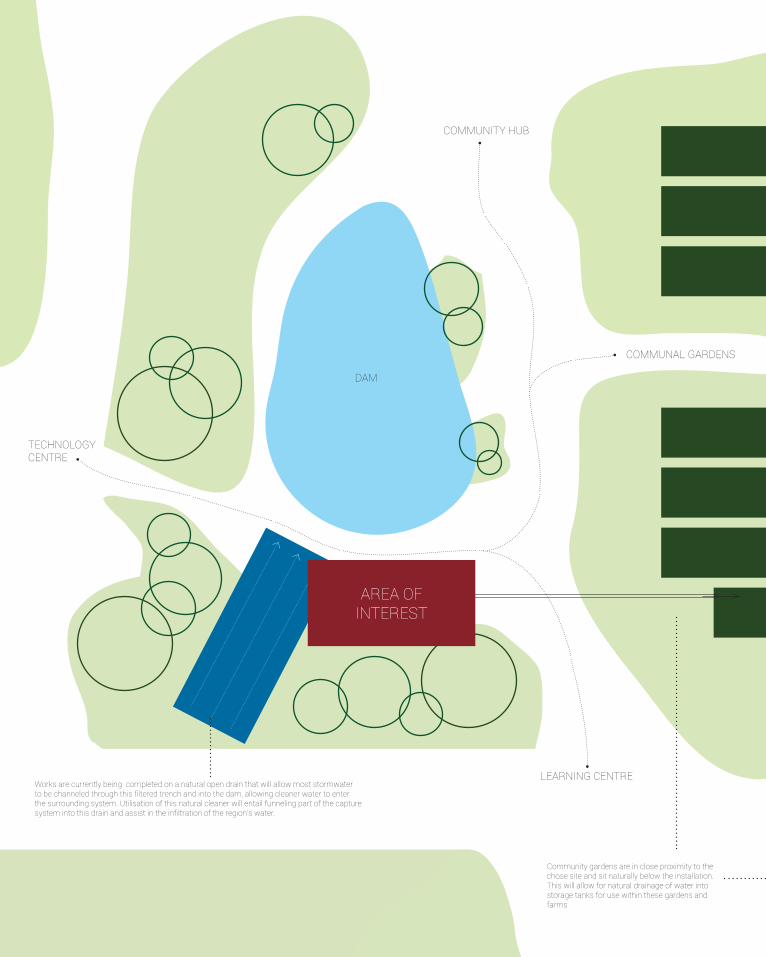
102
COMMUNAL GARDENS
LEARNING CENTRE
COMMUNITY HUB
TECHNOLOGY CENTRE
DAM
Works are currently being completed on a natural open drain that will allow most stormwater to be channeled through this filtered trench and into the dam, allowing cleaner water to enter the surrounding system. Utilisation of this natural cleaner will entail funneling part of the capture system into this drain and assist in the infiltration of the region’s water.
Community gardens are in close proximity to the chose site and sit naturally below the installation. This will allow for natural drainage of water into storage tanks for use within these gardens and farms
AREA OF INTEREST

103
This vector Illustration was created by DownloadFreeVector.com and it’s 100% royalty free for commercial purposes.You can share it on your site with two backlinks - to DownloadFreeVector.com and to homepage of this vector freebie(use post title as a text for link). In my work I’m using free vector silhouettes and Illustrations from all-silhouettes.com and vectorlady.com (useful resources of free vector illustrations).You are not allowed to share it without backlinks and sell it on stock sites as your own (take care about your karma).
COMMUNAL GARDENS
This vector Illustration was created by DownloadFreeVector.com and it’s 100% royalty free for commercial purposes.You can share it on your site with two backlinks - to DownloadFreeVector.com and to homepage of this vector freebie(use post title as a text for link). In my work I’m using free vector silhouettes and Illustrations from all-silhouettes.com and vectorlady.com (useful resources of free vector illustrations).You are not allowed to share it without backlinks and sell it on stock sites as your own (take care about your karma).
CAPTURE
DISTRIBUTE
UTILISE
PROTECT
The intention is to produce a membrane that is dynamic and changing in texture when touched. In doing so audiences are drawn to explore the project and discover more. The outer skin will comprise of an undulating surface with an interior layer to provide water proofing and allowing the capture of rainfall. In the nature of the site, material choice and colour will have to reflect both the strength required as well as blending in with the context of the site in its entirety.
The use of the site is predominantly young children and school groups and so protection from the sun and weather is important. While the main purpose is to capture rainfall, the added benefit is that there is now shading in this area, which from analy-sis of the CERES site as a whole is not very common. This both protects from UV radiation but also allows for usage to continue for various weather conditions.
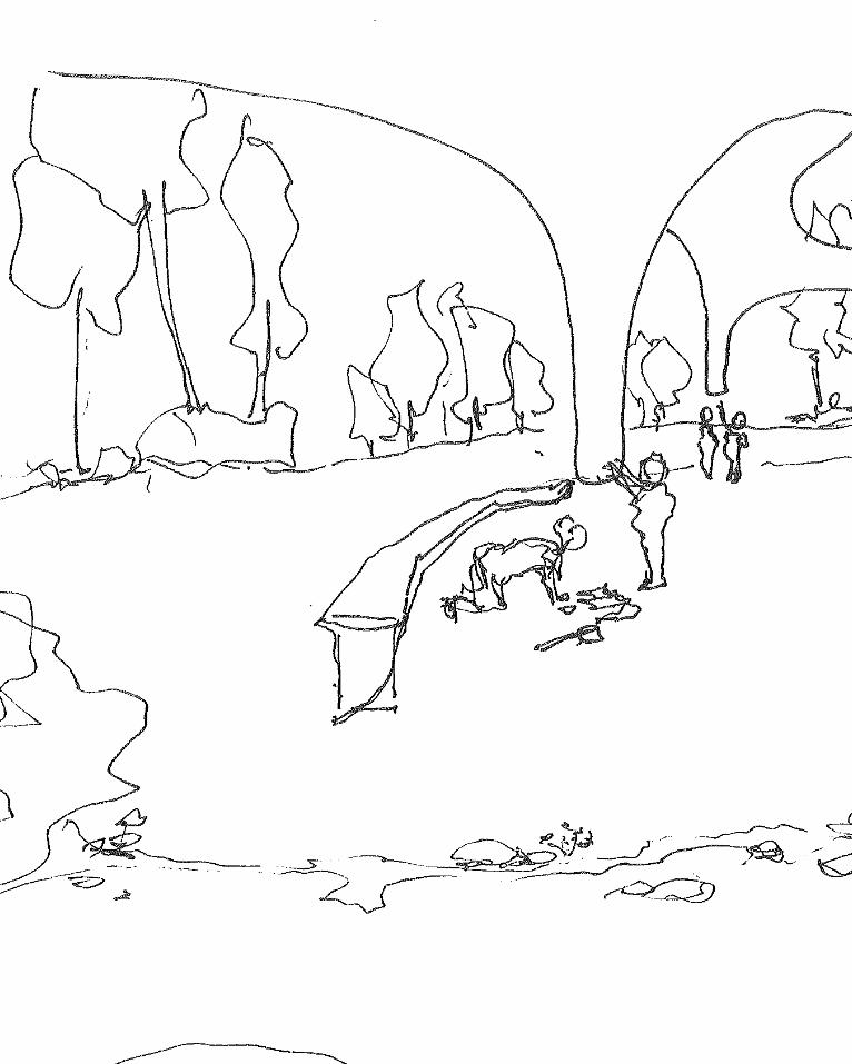
104
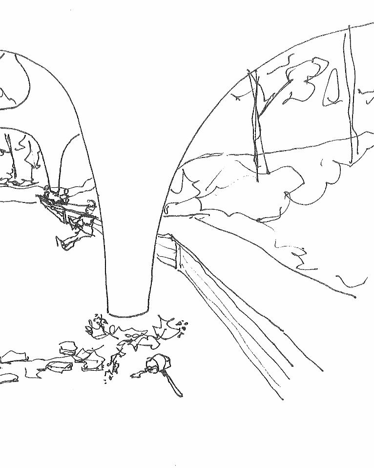
105
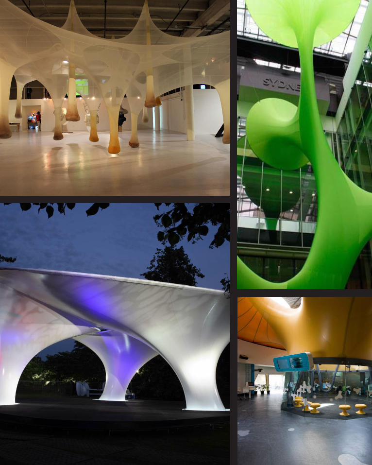
106
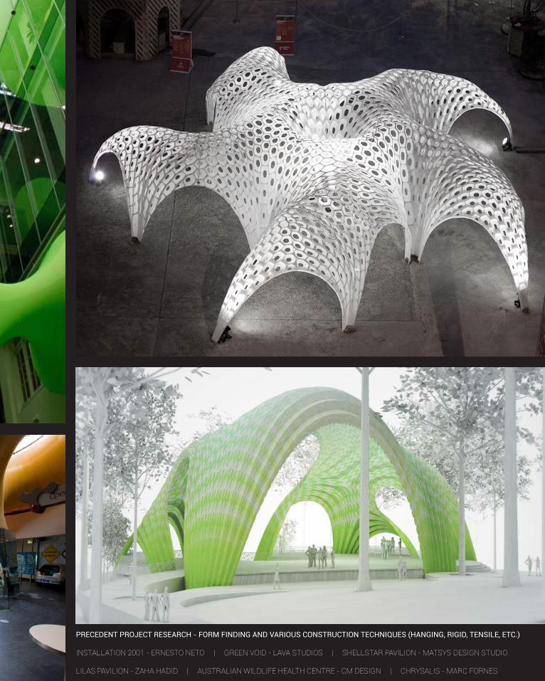
107
PRECEDENT PROJECT RESEARCH - FORM FINDING AND VARIOUS CONSTRUCTION TECHNIQUES (HANGING, RIGID, TENSILE, ETC.)
INSTALLATION 2001 - ERNESTO NETO | GREEN VOID - LAVA STUDIOS | SHELLSTAR PAVILION - MATSYS DESIGN STUDIO
LILAS PAVILION - ZAHA HADID | AUSTRALIAN WILDLIFE HEALTH CENTRE - CM DESIGN | CHRYSALIS - MARC FORNES
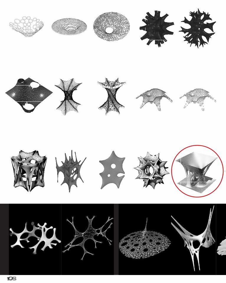
108
46 DESIGN CRITERIA
ITERATIONS MATRIX
46 DESIGN CRITERIA
ITERATIONS MATRIX
46 DESIGN CRITERIA
ITERATIONS MATRIX
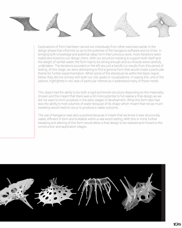
109
46 DESIGN CRITERIA
ITERATIONS MATRIX
Explorations of form had been carried out individually from other exercises earlier in the design phase that informed us as to the potential of the Kangaroo software and its limits. In bringing both knowledge and potential ideas form their previous work, more iterations were trialed and tested to our design intent. With our structure needing to support both itself and the weight of rainfall water, the form had to be strong enough and so choices were carefully undertaken. The iterations provided on the left are just a handful or results from this period of testing. At this stage, we were attempting to find a general form that would create a particular theme for further experimentation. While some of the standouts lie within the black region below, they did not comply with both our site, goals or visualisations. In saying this, one of the options, highlighted in red, was of particular interest as it addressed many of these needs.
This object had the ability to be both a rigid and tensile structure depending on the materiality chosen and this meant that there was a lot more potential to full realise a final design as we did not want to limit ourselves in the early stages of development. What this form also had was the ability to hold volumes of water because of its shape which meant that not as much tweaking would need to occur to produce a viable outcome.
The use of kangaroo was also a positive because it meant that we know it was structurally viable, efficient in form and buildable within a real world setting. With this in mind, further tweaking and altering of this form would allow a final design to be realised and moved to the construction and application stages.
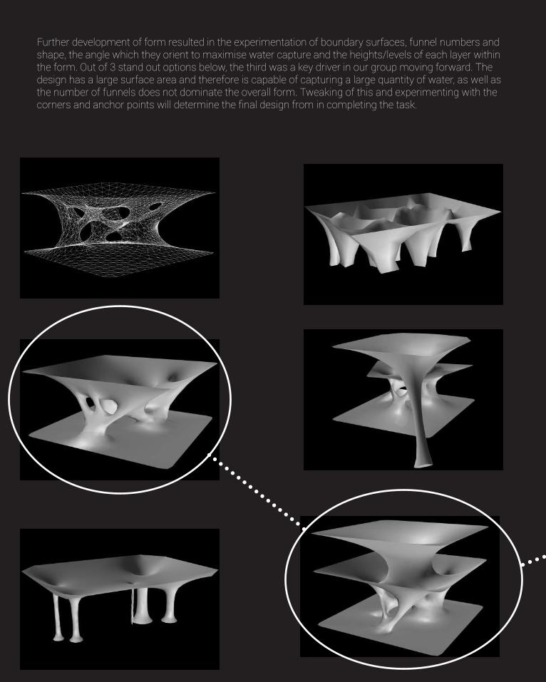
110
Further development of form resulted in the experimentation of boundary surfaces, funnel numbers and shape, the angle which they orient to maximise water capture and the heights/levels of each layer within the form. Out of 3 stand out options below, the third was a key driver in our group moving forward. The design has a large surface area and therefore is capable of capturing a large quantity of water, as well as the number of funnels does not dominate the overall form. Tweaking of this and experimenting with the corners and anchor points will determine the final design from in completing the task.
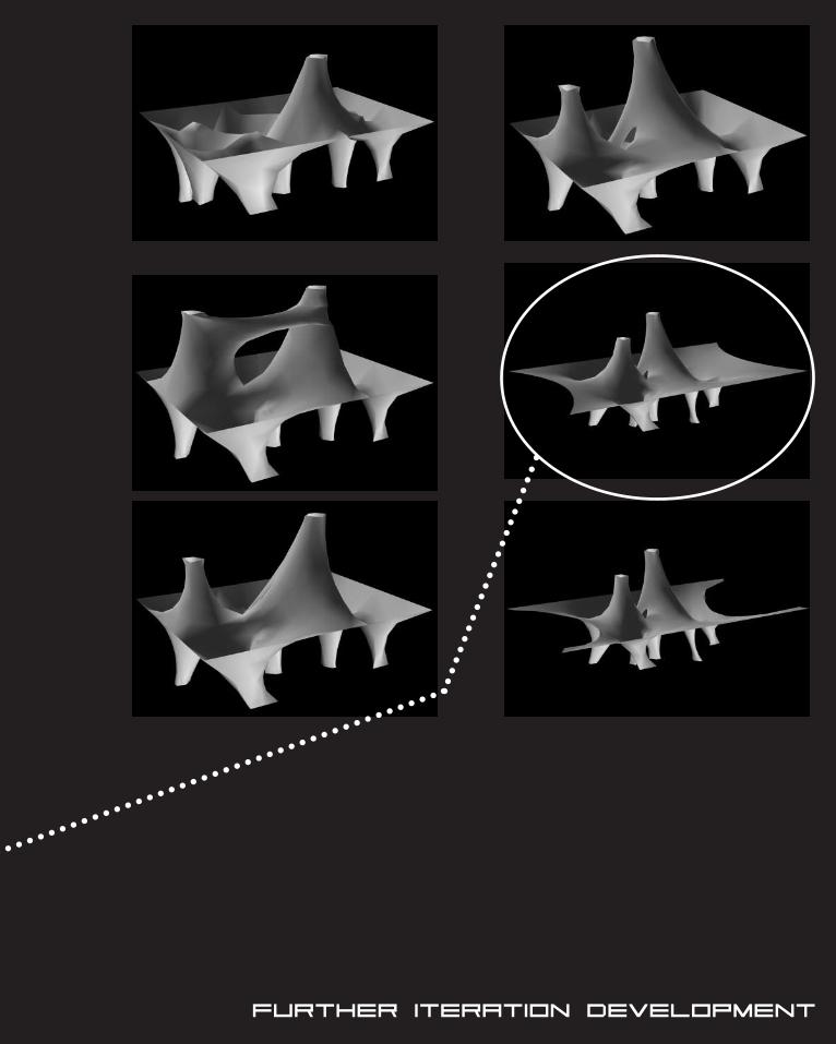
111Further Iteration Development
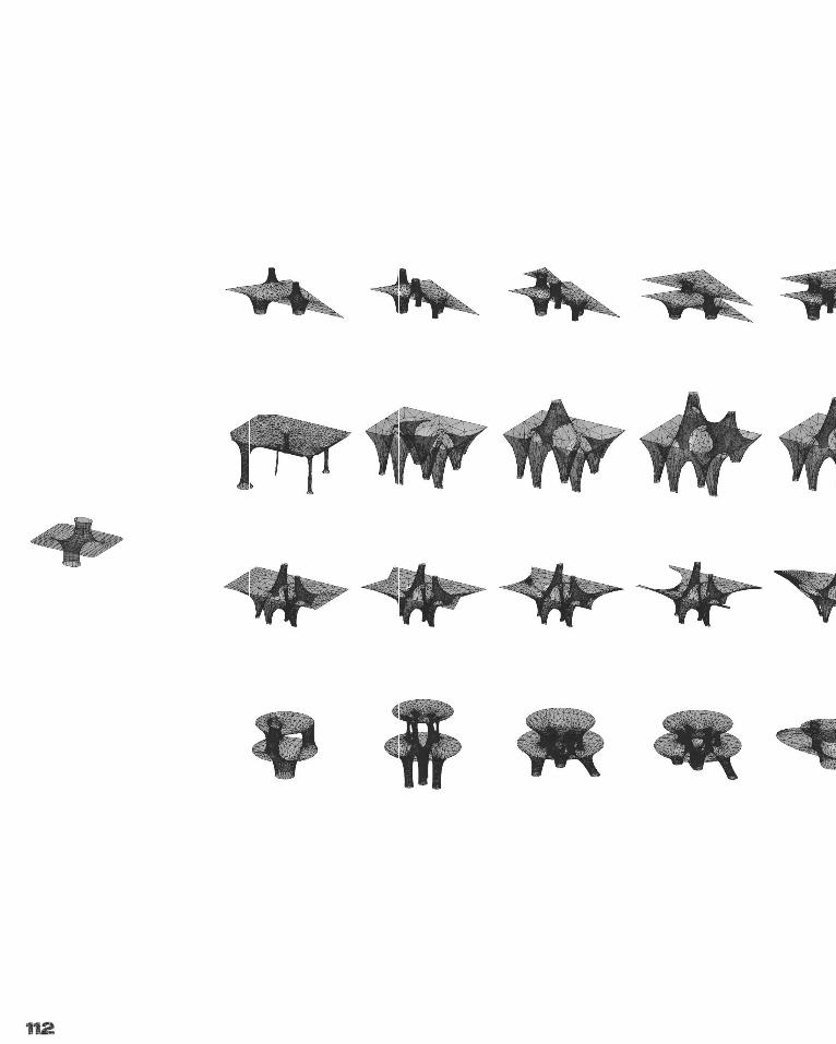
112
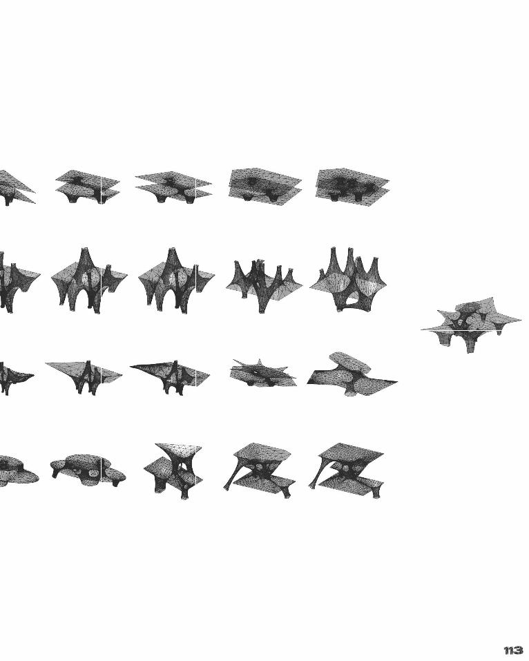
113
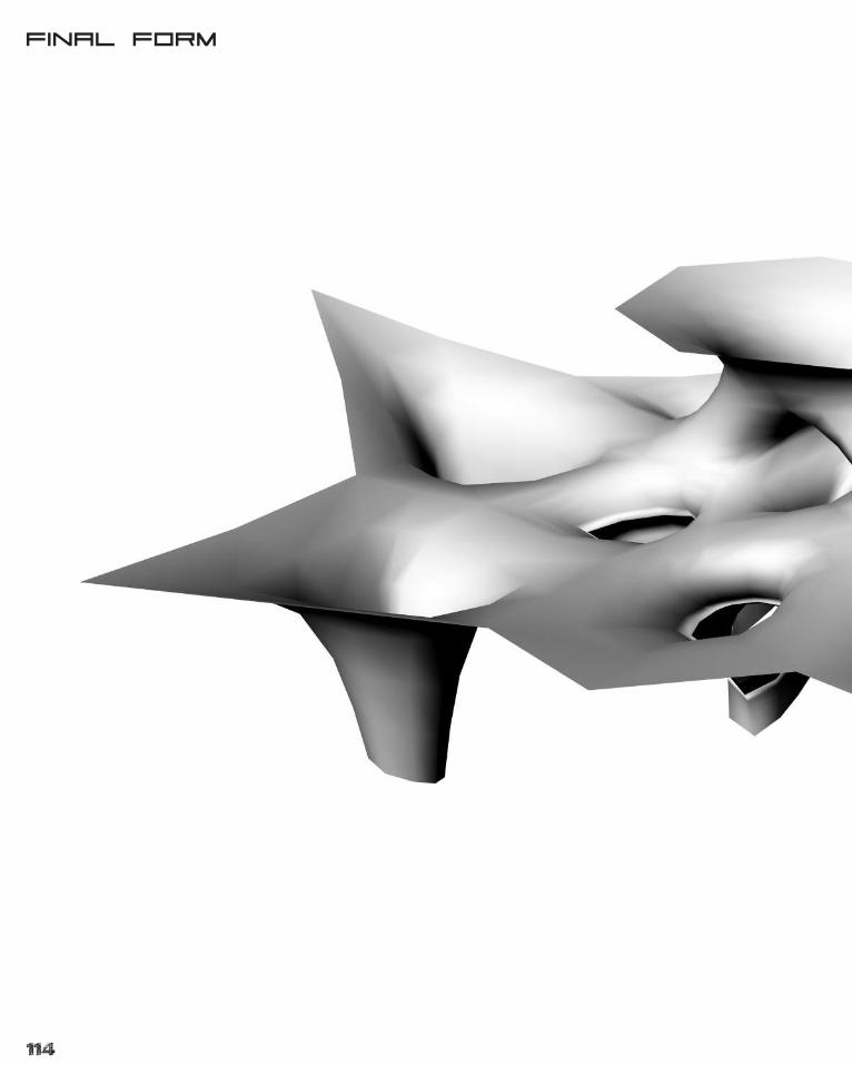
114
Final Form
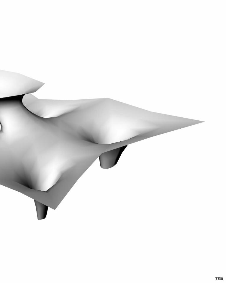
115

116
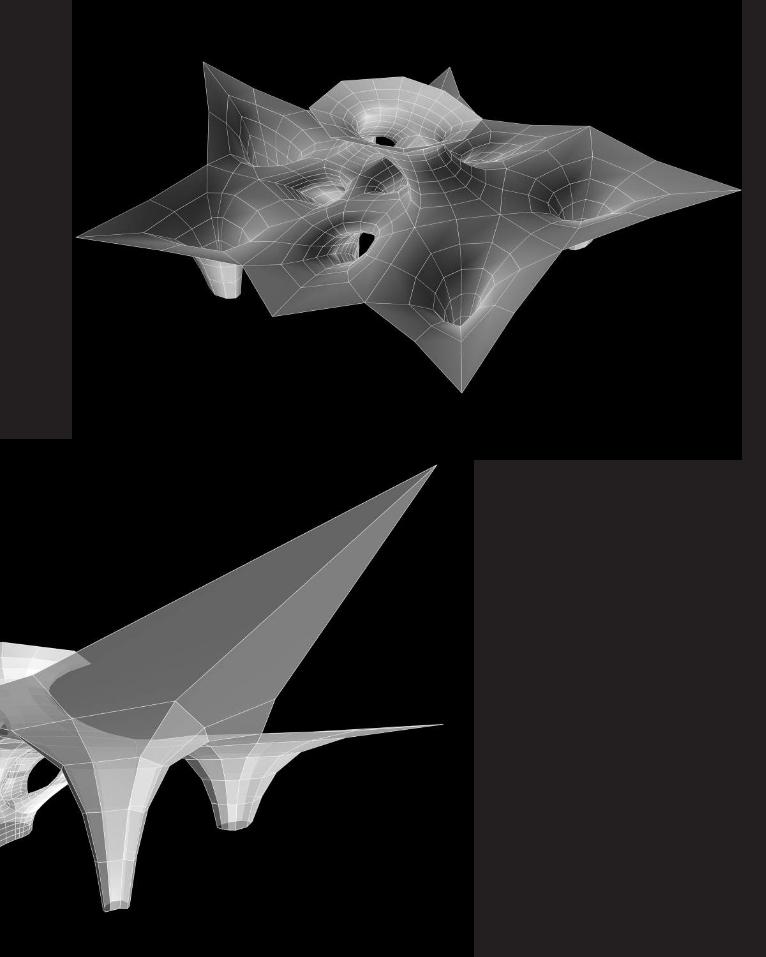
117
118
119
The structure maintains a partial shape due to the cable ties being a semi-rigid structure, however when there is no live load on the surface, it will tend to flex more and be more vulnerable to wind and other forces. This results in a more flat structure with only some solid form.
As rain begins to fall the structure will slowly flex and warp into a more tensile shape. As some of the funnels connect to the ground, less shifting will occur however for valve and hose connections, these areas will begin to fall and take form.
After a longer period of rain, it will begin to complete its form and resemble the desired shape. At this stage, the structure will have reached the ground and have an ability to be interact with the children and excursion groups, increasing the awareness of the processes occurring in the site.
120
Construction Development
121
Construction Development
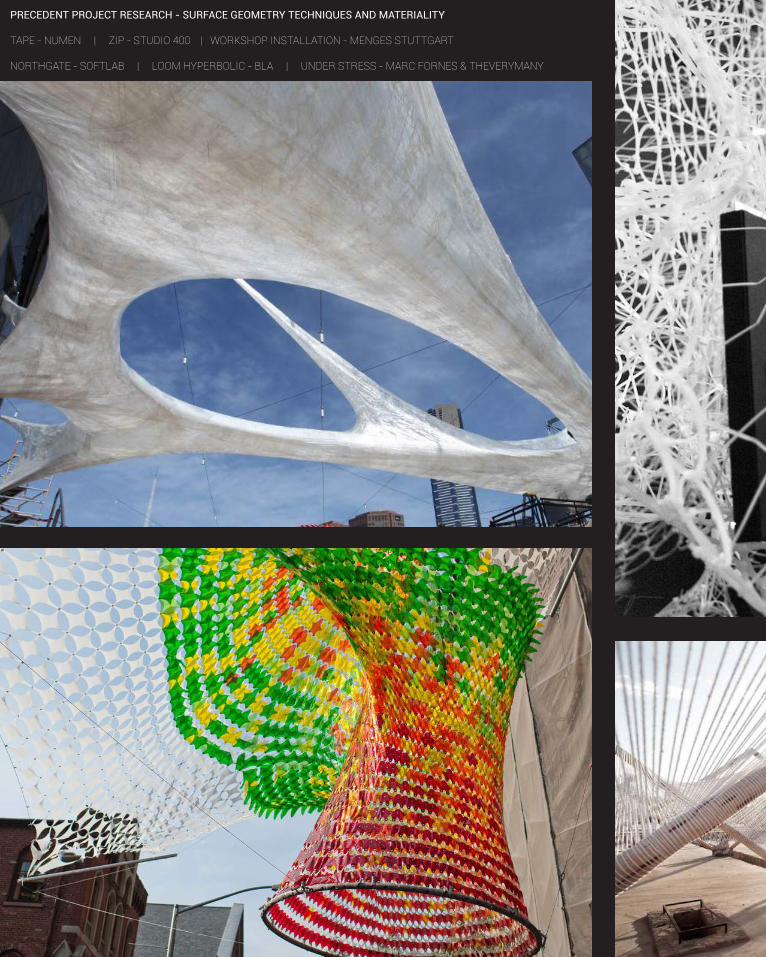
122
PRECEDENT PROJECT RESEARCH - SURFACE GEOMETRY TECHNIQUES AND MATERIALITY
TAPE - NUMEN | ZIP - STUDIO 400 | WORKSHOP INSTALLATION - MENGES STUTTGART
NORTHGATE - SOFTLAB | LOOM HYPERBOLIC - BLA | UNDER STRESS - MARC FORNES & THEVERYMANY
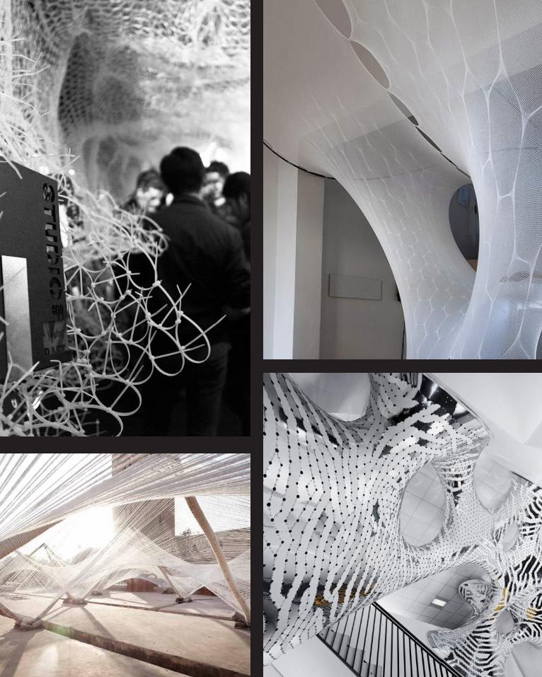
123

124
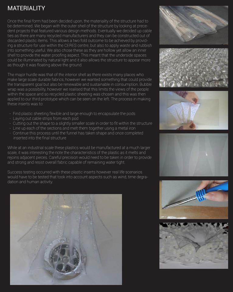
125
MATERIALITY
Once the final form had been decided upon, the materiality of the structure had to be determined. We began with the outer shell of the structure by looking at prece-dent projects that featured various design methods. Eventually we decided up cable ties as there are many recycled manufacturers and they can be constructed out of discarded plastic items. This allows a two fold outcome to be achieved by provid-ing a structure for use within the CERES centre, but also to apply waste and rubbish into something useful. We also chose these as they are hollow yet allow an inner shell to provide the water proofing aspect. This meant that the underside spaces could be illuminated by natural light and it also allows the structure to appear more as though it was floating above the ground.
The major hurdle was that of the interior shell as there exists many places who make large scale durable fabrics, however we wanted something that could provide the transparent goal but also be renewable and sustainable in consumption. Bubble wrap was a possibility, however we realised that this limits the views of the people within the space and so recycled plastic sheeting was chosen and this was then applied to our third prototype which can be seen on the left. The process in making these inserts was to:
- Find plastic sheeting flexible and large enough to encapsulate the pods - Laying out cable strips from each pod - Cutting out the shape to a slightly smaller scale in order to fit within the structure - Line up each of the sections and melt them together using a metal iron - Continue this process until the funnel has taken shape and once completed inserted into the final structure
While at an industrial scale these plastics would be manufactured at a much larger scale, it was interesting the note the characteristics of the plastic as it melts and rejoins adjacent pieces. Careful precision would need to be taken in order to provide and strong and resist overall fabric capable of remaining water tight.
Success testing occurred with these plastic inserts however real life scenarios would have to be tested that took into account aspects such as wind, time degra-dation and human activity.
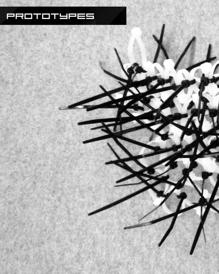
126
Prototypes
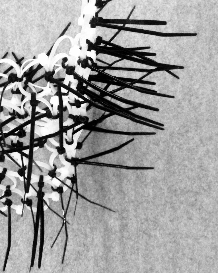
127
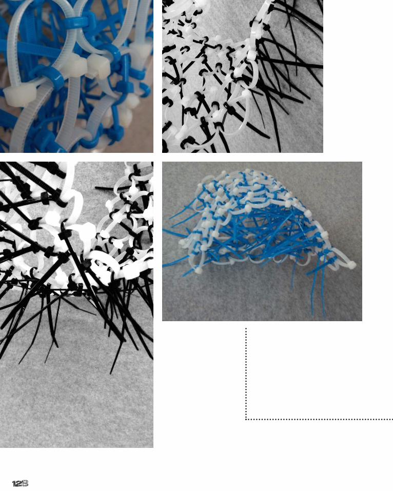
128
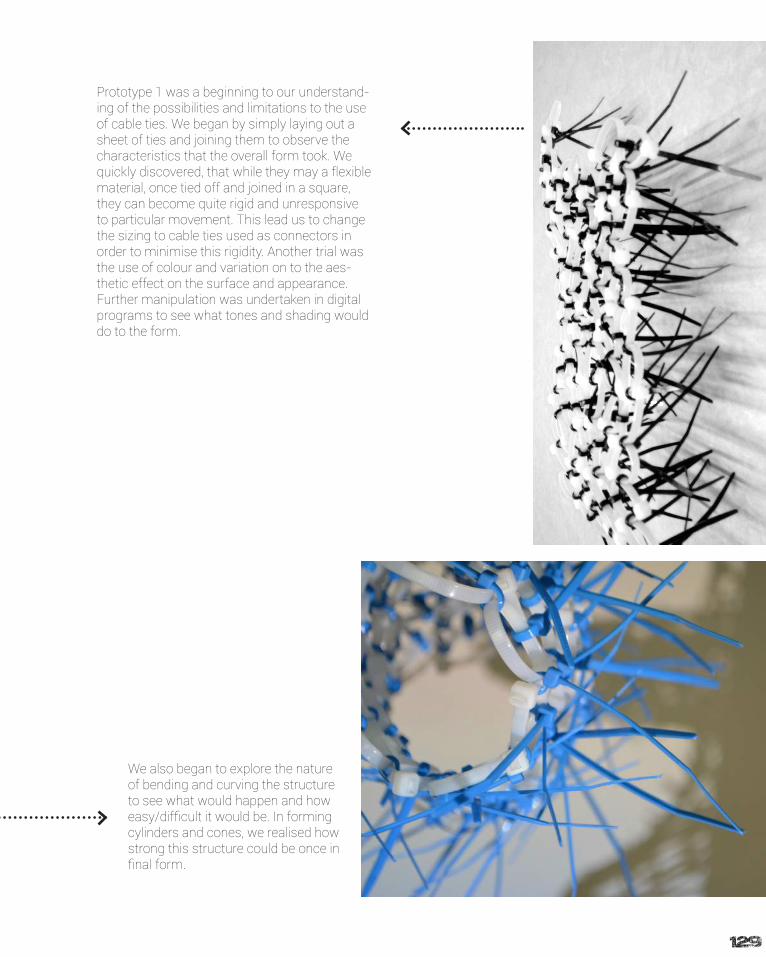
129
Prototype 1 was a beginning to our understand-ing of the possibilities and limitations to the use of cable ties. We began by simply laying out a sheet of ties and joining them to observe the characteristics that the overall form took. We quickly discovered, that while they may a flexible material, once tied off and joined in a square, they can become quite rigid and unresponsive to particular movement. This lead us to change the sizing to cable ties used as connectors in order to minimise this rigidity. Another trial was the use of colour and variation on to the aes-thetic effect on the surface and appearance. Further manipulation was undertaken in digital programs to see what tones and shading would do to the form.
We also began to explore the nature of bending and curving the structure to see what would happen and how easy/difficult it would be. In forming cylinders and cones, we realised how strong this structure could be once in final form.
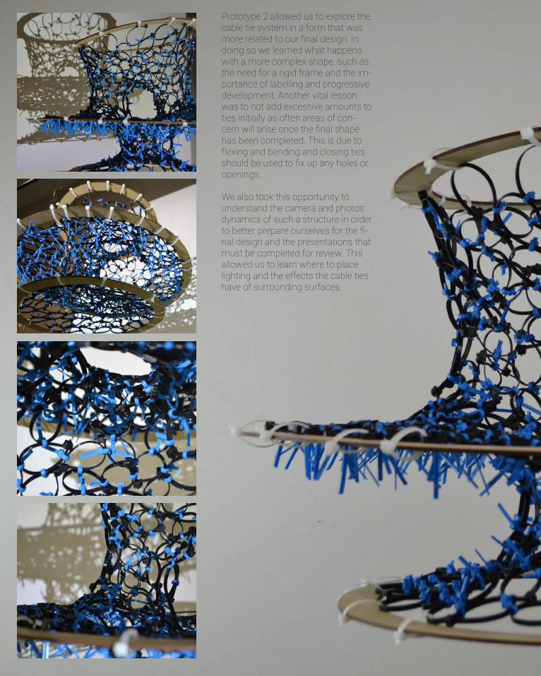
130
Prototype 2 allowed us to explore the cable tie system in a form that was more related to our final design. In doing so we learned what happens with a more complex shape, such as the need for a rigid frame and the im-portance of labelling and progressive development. Another vital lesson was to not add excessive amounts to ties initially as often areas of con-cern will arise once the final shape has been completed. This is due to flexing and bending and closing ties should be used to fix up any holes or openings.
We also took this opportunity to understand the camera and photos dynamics of such a structure in order to better prepare ourselves for the fi-nal design and the presentations that must be completed for review. This allowed us to learn where to place lighting and the effects the cable ties have of surrounding surfaces.
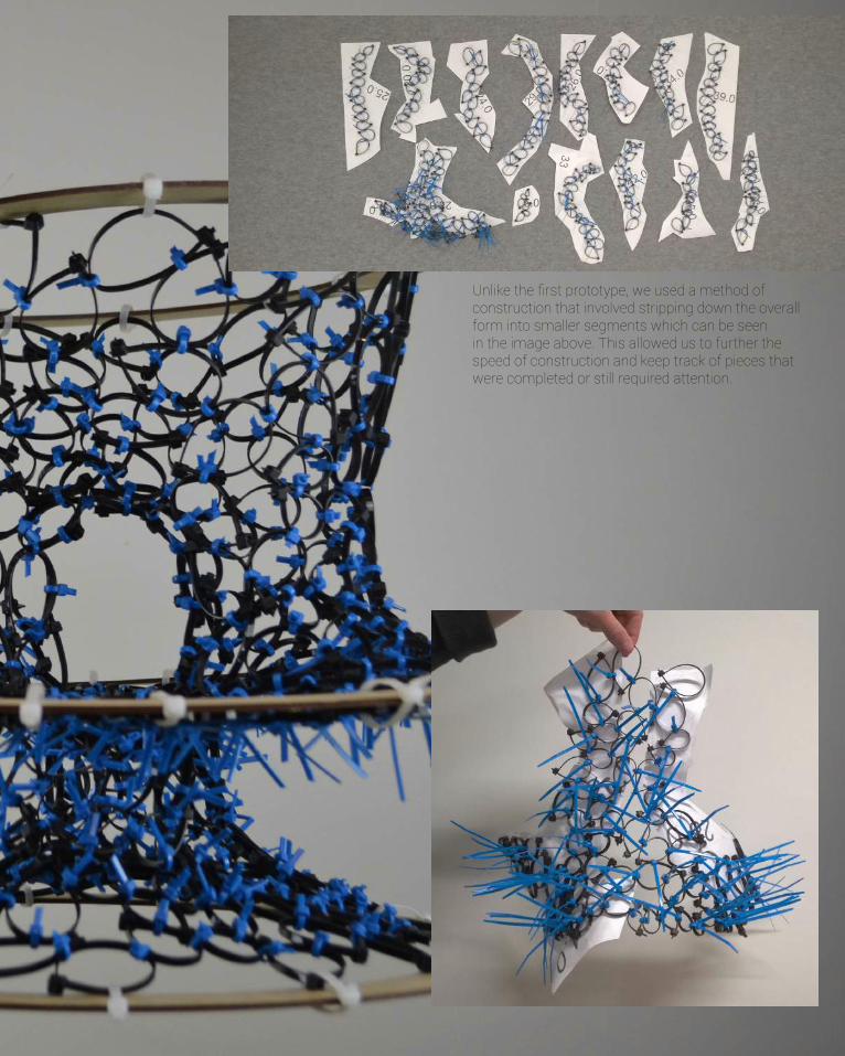
131
Unlike the first prototype, we used a method of construction that involved stripping down the overall form into smaller segments which can be seen in the image above. This allowed us to further the speed of construction and keep track of pieces that were completed or still required attention.
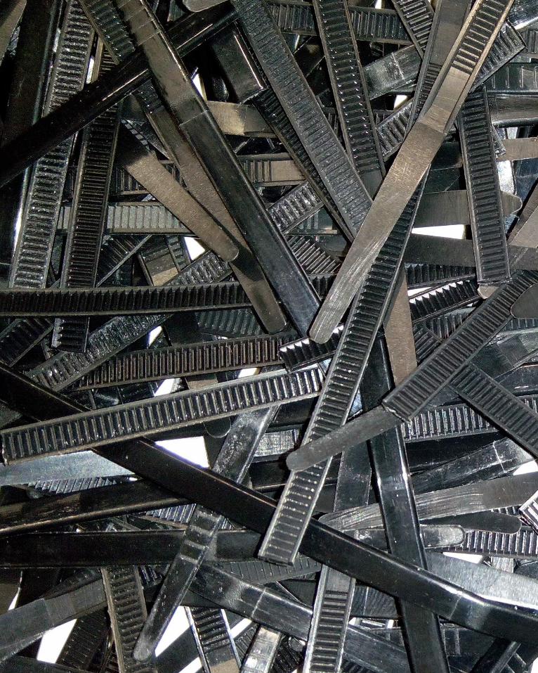
132
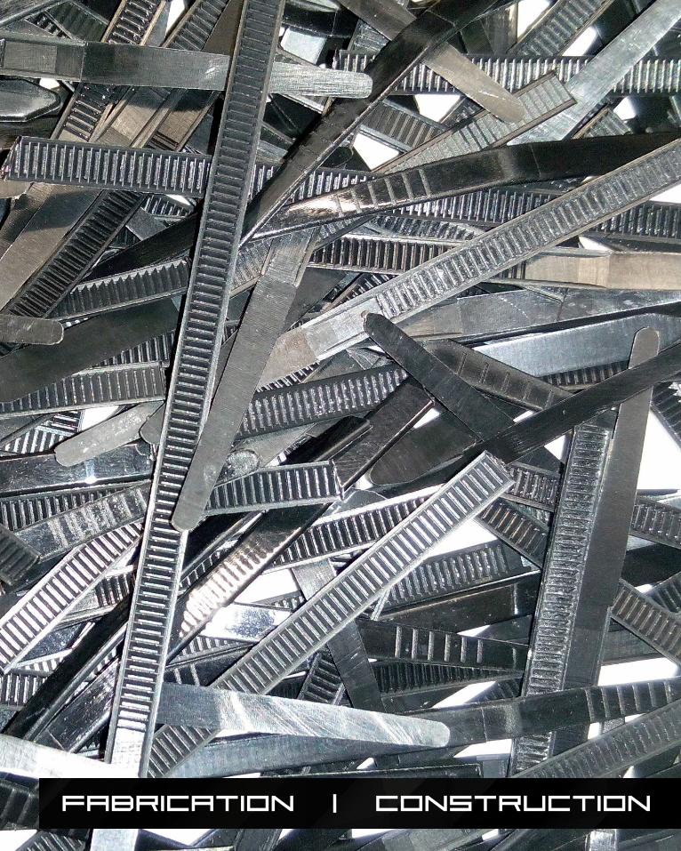
133
FABRICATION | CONSTRUCTION
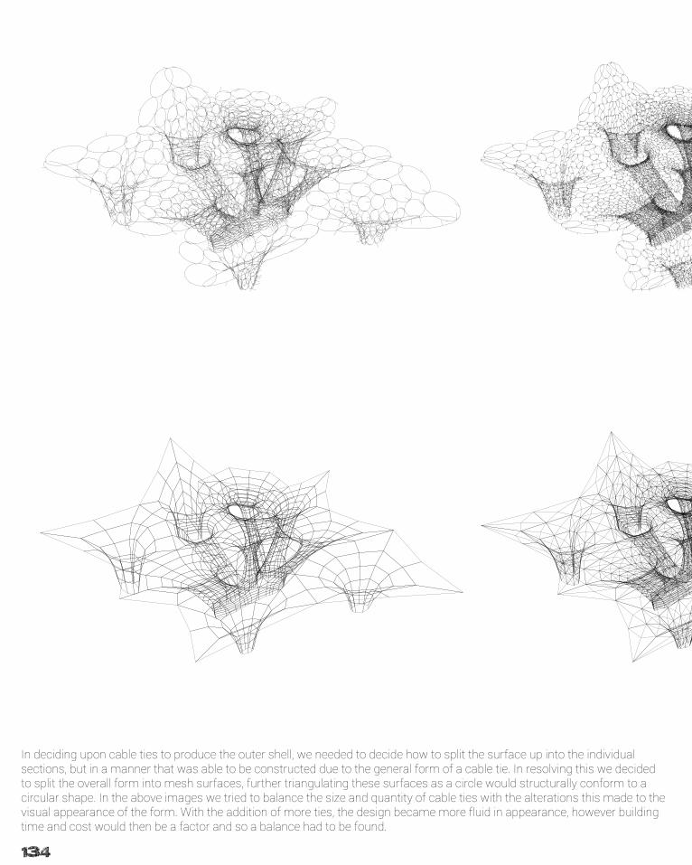
134
In deciding upon cable ties to produce the outer shell, we needed to decide how to split the surface up into the individual sections, but in a manner that was able to be constructed due to the general form of a cable tie. In resolving this we decided to split the overall form into mesh surfaces, further triangulating these surfaces as a circle would structurally conform to a circular shape. In the above images we tried to balance the size and quantity of cable ties with the alterations this made to the visual appearance of the form. With the addition of more ties, the design became more fluid in appearance, however building time and cost would then be a factor and so a balance had to be found.
135
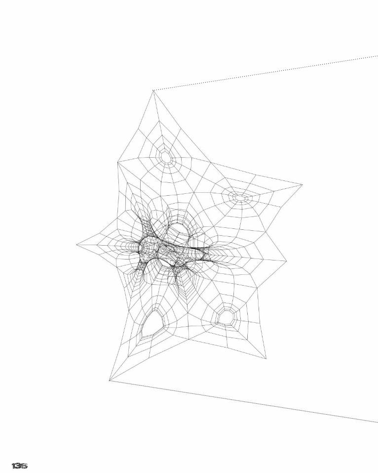
136
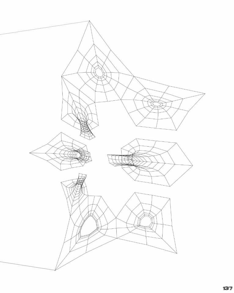
137
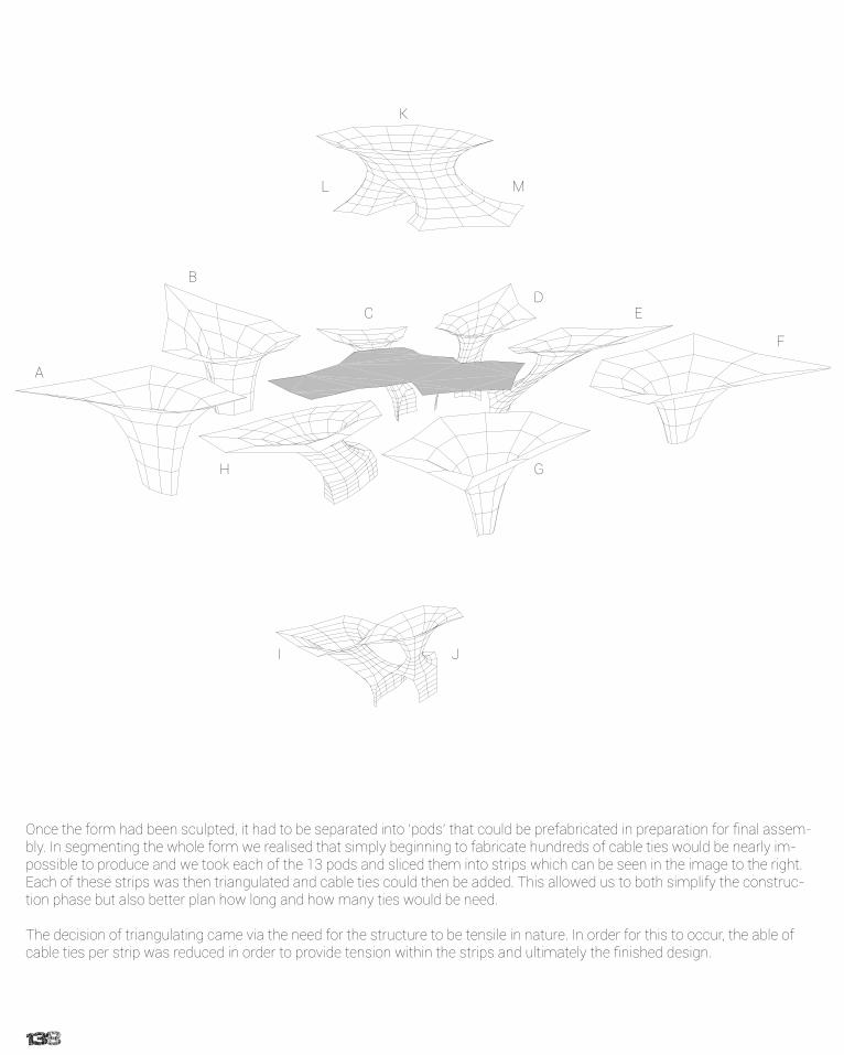
138
7.0
6.05.04.0
3.02.01.00.0 9.0
7.0 8.0 9.0
6.05.0
4.03.02.01.0
0.0
0.0 1.0 2.0 3.04.0 5.
0
6.0
7.0 8.0 9.010.0 11.0
15.0
14.013.012.011.0
10.09.08.07.06.05.04.03.02.01.00.0
11.0
10.0
9.0
8.07.0
6.0
5.04.03.02.0
1.0
0.0
8.07.0 11.0
6.0
10.09.05.04.03.02.01.00.0
3 4
56 7
20.0
1
0.0
2.0
1.0
3.0
4.0
5.0
6.0 7.0 8.0 9.0
9.08.0
7.06.0
5.03.02.01.00.0 4.
0
0.0
1.0 2.0
3.0 4.0
5.06.0 7.0
8.0
9.0
9.0
8.0
7.0
6.05.04.03.02.01.0
0.0
5.01.00.0 2.0 3.0 4.0 8.0
9.0
7.0
6.0
3 4 5 67
1.0
20.0
10.0
12.09.0
8
8.0
M
B
C
I
A
D
H
K
G
L
F
J
E
Once the form had been sculpted, it had to be separated into ‘pods’ that could be prefabricated in preparation for final assem-bly. In segmenting the whole form we realised that simply beginning to fabricate hundreds of cable ties would be nearly im-possible to produce and we took each of the 13 pods and sliced them into strips which can be seen in the image to the right. Each of these strips was then triangulated and cable ties could then be added. This allowed us to both simplify the construc-tion phase but also better plan how long and how many ties would be need.
The decision of triangulating came via the need for the structure to be tensile in nature. In order for this to occur, the able of cable ties per strip was reduced in order to provide tension within the strips and ultimately the finished design.

139
7.0
6.05.04.0
3.02.01.00.0 9.0
7.0 8.0 9.0
6.05.0
4.03.02.01.0
0.0
0.0 1.0 2.0 3.04.0 5.
0
6.0
7.0 8.0 9.010.0 11.0
15.0
14.013.012.011.0
10.09.08.07.06.05.04.03.02.01.00.0
11.0
10.0
9.0
8.07.0
6.0
5.04.03.02.0
1.0
0.0
8.07.0 11.0
6.0
10.09.05.04.03.02.01.00.0
3 4
56 7
20.0
1
0.0
2.0
1.0
3.0
4.0
5.0
6.0 7.0 8.0 9.0
9.08.0
7.06.0
5.03.02.01.00.0 4.
0
0.0
1.0 2.0
3.0 4.0
5.06.0 7.0
8.0
9.0
9.0
8.0
7.0
6.05.04.03.02.01.0
0.0
5.01.00.0 2.0 3.0 4.0 8.0
9.0
7.0
6.0
3 4 5 67
1.0
20.0
10.0
12.09.0
8
8.0
7.0
6.05.04.0
3.02.01.00.0 9.0
7.0 8.0 9.0
6.05.0
4.03.02.01.0
0.0
0.0 1.0 2.0 3.04.0 5.
0
6.0
7.0 8.0 9.010.0 11.0
15.0
14.013.012.011.0
10.09.08.07.06.05.04.03.02.01.00.0
11.0
10.0
9.0
8.07.0
6.0
5.04.03.02.0
1.0
0.0
8.07.0 11.0
6.0
10.09.05.04.03.02.01.00.0
3 4
56 7
20.0
1
0.0
2.0
1.0
3.0
4.0
5.0
6.0 7.0 8.0 9.0
9.08.0
7.06.0
5.03.02.01.00.0 4.
0
0.0
1.0 2.0
3.0 4.0
5.06.0 7.0
8.0
9.0
9.0
8.0
7.0
6.05.04.03.02.01.0
0.0
5.01.00.0 2.0 3.0 4.0 8.0
9.0
7.0
6.0
3 4 5 67
1.0
20.0
10.012.0
9.0
8
8.0
7.0
6.05.04.0
3.02.01.00.0 9.0
7.0 8.0 9.0
6.05.0
4.03.02.01.0
0.0
0.0 1.0 2.0 3.04.0 5.
0
6.0
7.0 8.0 9.010.0 11.0
15.0
14.013.012.011.0
10.09.08.07.06.05.04.03.02.01.00.0
11.0
10.0
9.0
8.07.0
6.0
5.04.03.02.0
1.0
0.0
8.07.0 11.0
6.0
10.09.05.04.03.02.01.00.0
3 4
56 7
20.0
1
0.0
2.0
1.0
3.0
4.0
5.0
6.0 7.0 8.0 9.0
9.08.0
7.06.0
5.03.02.01.00.0 4.
0
0.0
1.0 2.0
3.0 4.0
5.06.0 7.0
8.0
9.0
9.0
8.0
7.0
6.05.04.03.02.01.00.0
5.01.00.0 2.0 3.0 4.0 8.0
9.0
7.0
6.0
3 4 5 67
1.0
20.0
10.0
12.09.0
8
8.0
7.0
6.05.04.0
3.02.01.00.0 9.0
7.0 8.0 9.0
6.05.0
4.03.02.01.0
0.0
0.0 1.0 2.0 3.04.0 5.
0
6.0
7.0 8.0 9.010.0 11.0
15.0
14.013.012.011.0
10.09.08.07.06.05.04.03.02.01.00.0
11.0
10.0
9.0
8.07.0
6.0
5.04.03.02.0
1.0
0.0
8.07.0 11.0
6.0
10.09.05.04.03.02.01.00.0
3 4
56 7
20.0
1
0.0
2.0
1.0
3.0
4.0
5.0
6.0 7.0 8.0 9.0
9.08.0
7.06.0
5.03.02.01.00.0 4.
0
0.0
1.0 2.0
3.0 4.0
5.06.0 7.0
8.0
9.0
9.0
8.0
7.0
6.05.04.03.02.01.0
0.0
5.01.00.0 2.0 3.0 4.0 8.0
9.0
7.0
6.0
3 4 5 67
1.0
20.0
10.0
12.09.0
8
8.0
M
B
C
I
A
D
H
K
G
L
F
J
E
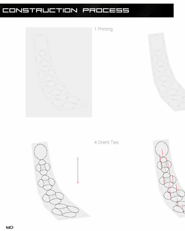
140
CONSTRUCTION Process
1 Printing
4 Orient Ties
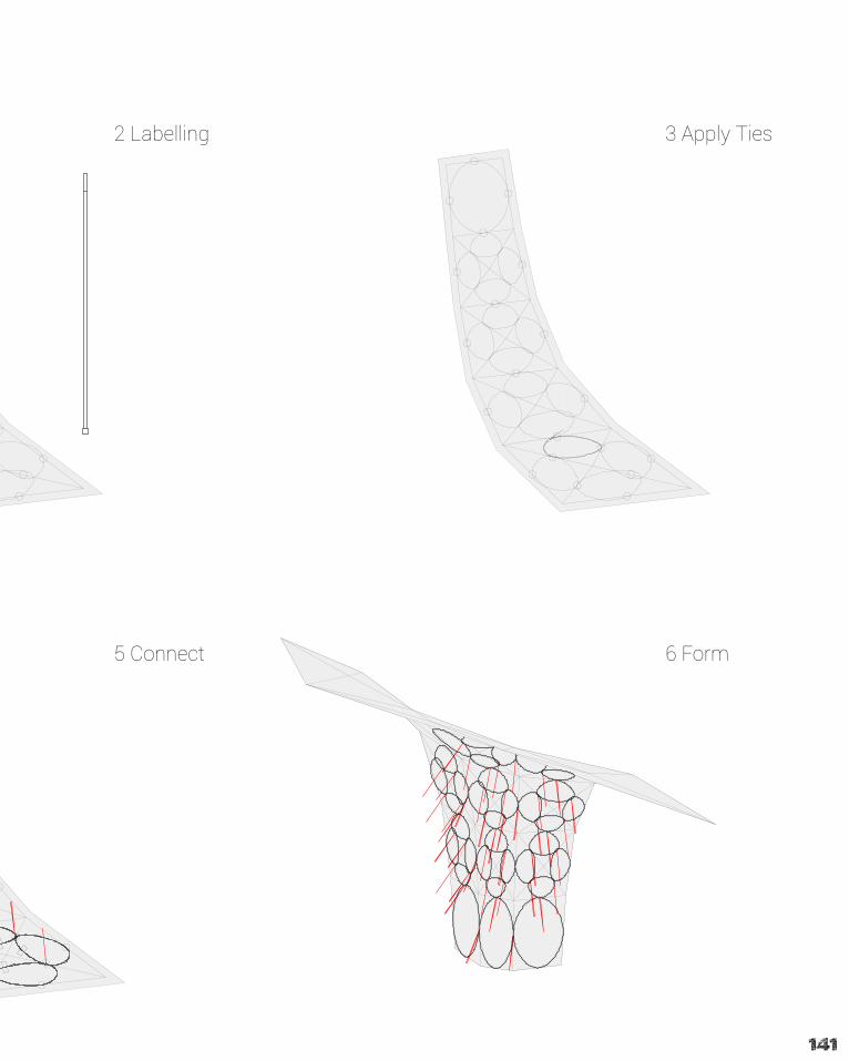
141
2 Labelling 3 Apply Ties
5 Connect 6 Form
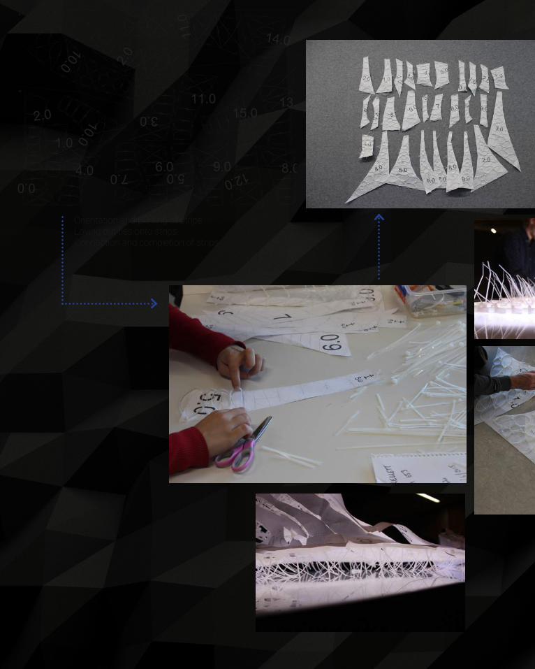
142
M
A
Orientation and printing of stripsLaying out ties onto stripsConnection and completion of strips
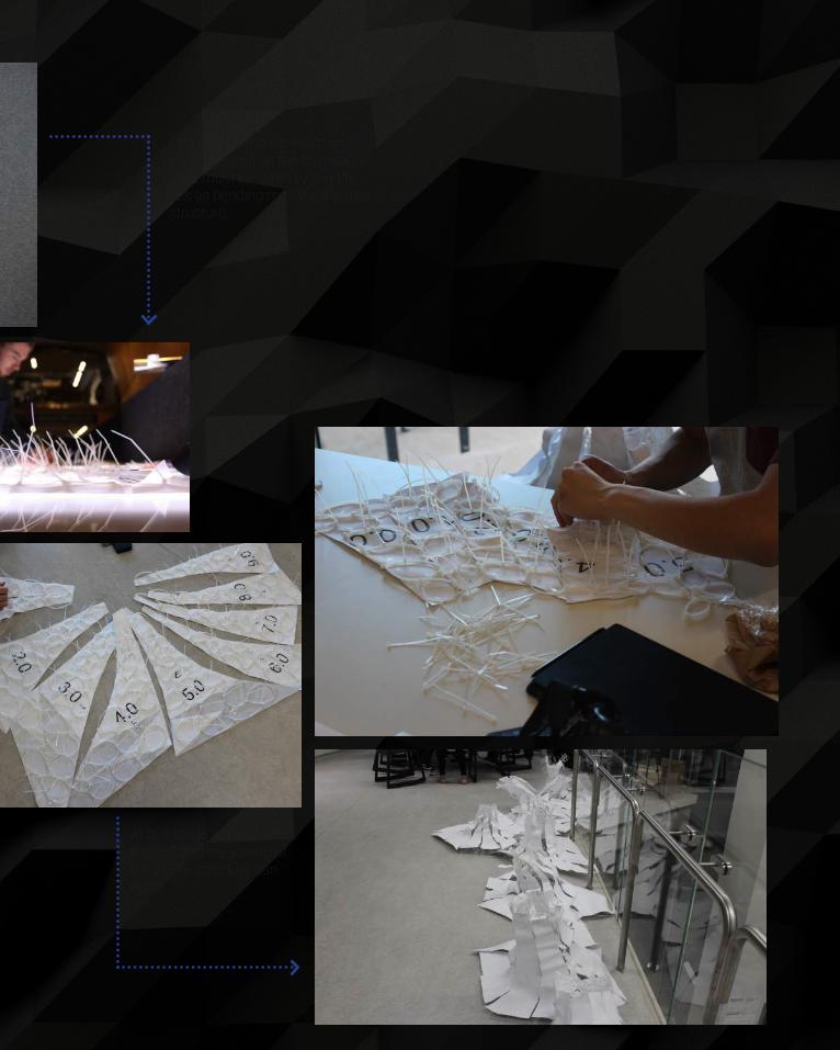
143
Each pod is then collated andjoining begins on the formation.Care must be taken to join theties as bending may weaken thestructure.
At this stage all pods areformed and the joining ofthe whole structure canoccur.

144
The central section ismade first and hungso that all other piecescan simply be added

145
The central section ismade first and hungso that all other piecescan simply be added

146DRIP TIES
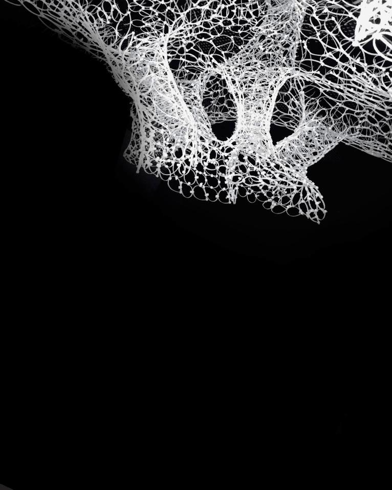
147
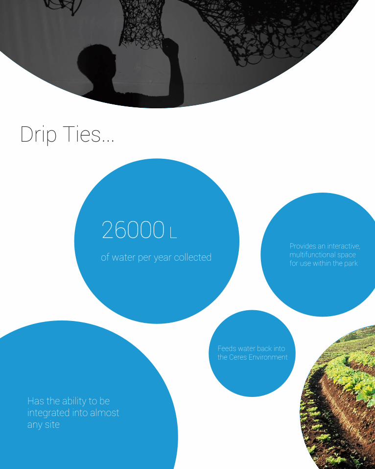
148
Drip Ties...
26000 L of water per year collected
Feeds water back into the Ceres Environment
Provides an interactive, multifunctional space for use within the park
Has the ability to be integrated into almost any site

149
Drip Ties is a multi-functional installation that provides both shelter and water capturing systems. By integrating these elements a seamless and interactive space has been created. Shading over the pond auditorium allows functional use in an condition and this proximity to natural water systems allows full integration of the system. In capturing water, the project aims to:
- Direct water into storage facilities for use within the centre’s gardens and farms - Naturally filter captured water back into the basin and water course
In allowing this water to be naturally discharged back into the ground, surrounding water systems are kept more healthy and surface runoff damage is avoided. Due to the built nature of the site, capturing this water and feeding it back into the system also removes potential envi-ronmental damage from erosion degradation of local landscapes via surface runoff.
Use within the gardens have a myriad of advantages:
- Captured water can be used in place of mains water for toilets, gardening, farms and upkeep/safety - Virtual water lost in mass food production is saved through the local gardens and farms when using this captured rainwater - Costs and fees are reduced from removing mains supply and can be reintroduced back to Ceres in other programs and initiatives
Potable water is a precious commodity and by removing this need from the site, utilisation can occur for more required tasks:
1. 160L is used on average for showering daily2. 80L for general daily usage - Washing hands, etc.3. 45L for toilet flushing each day4. 1000L per hour for automated sprinkler systems5. 100L per hour for washing around properties
Allows the park to become primarily self sufficient

150

151

152
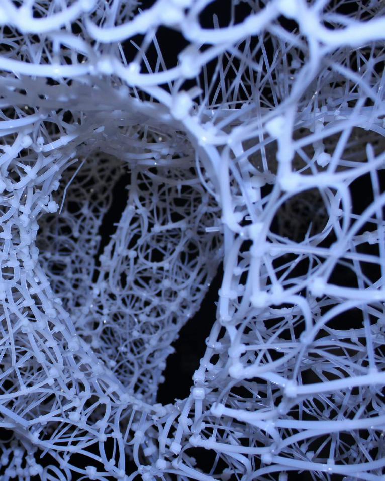
153
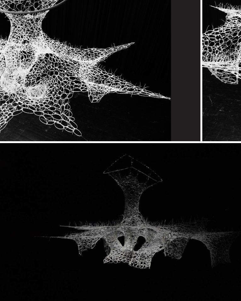
154
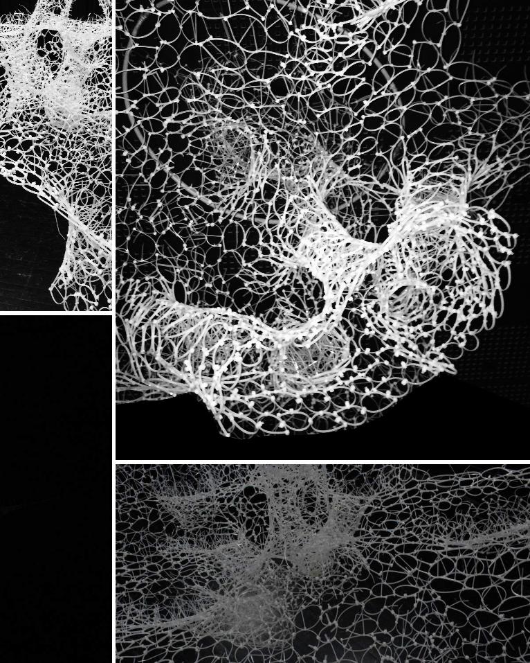
155

156
157
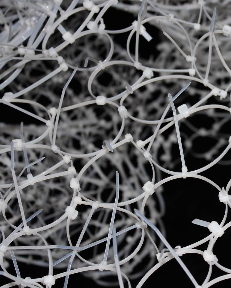
158
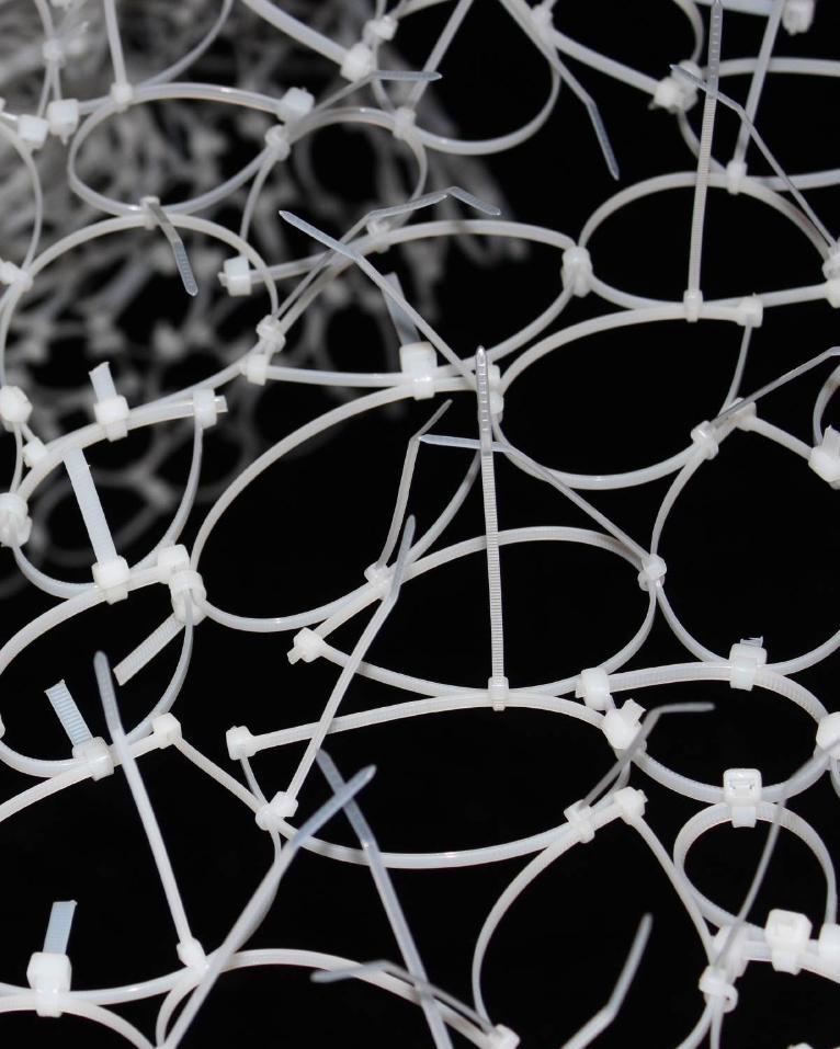
159
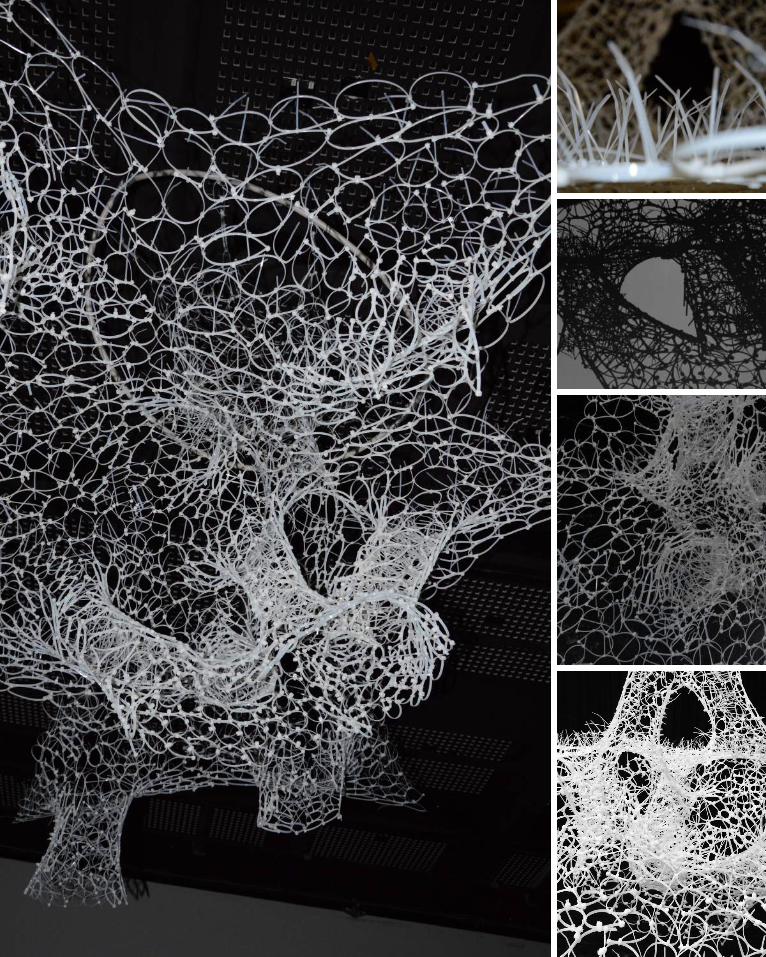
160
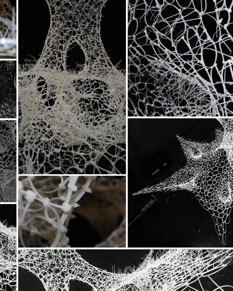
161
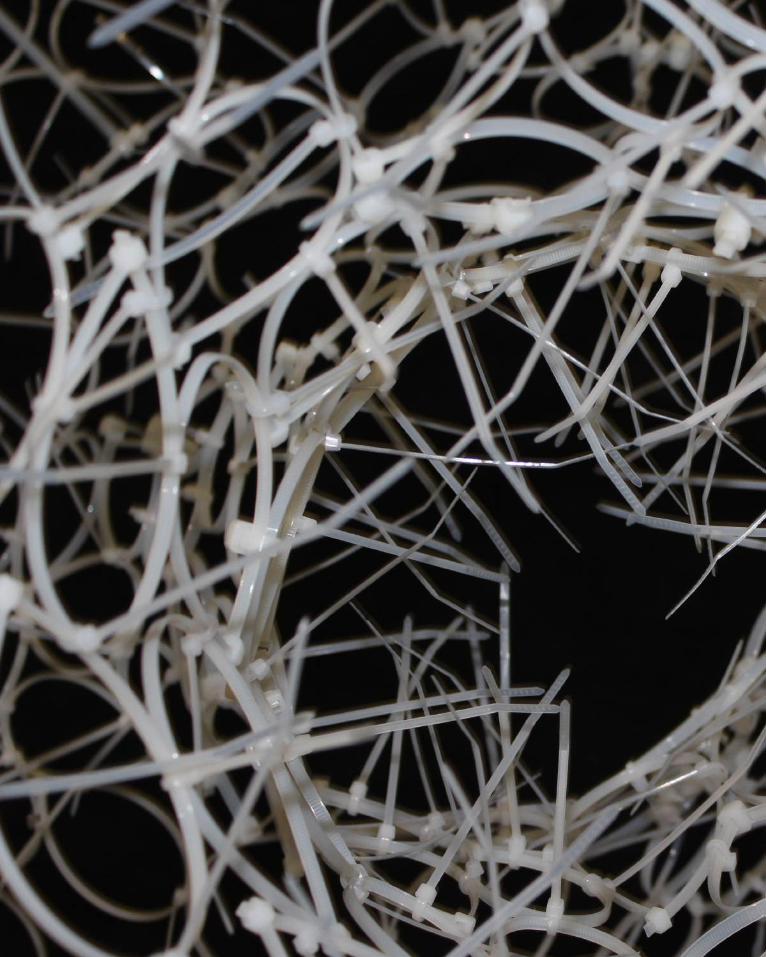
162
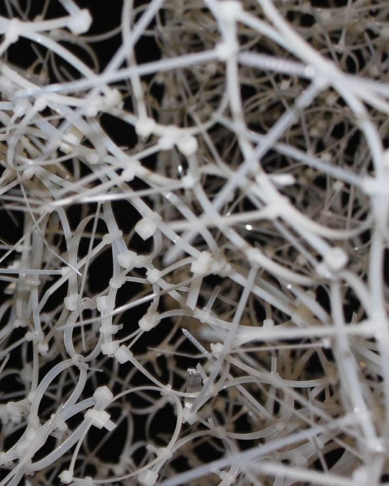
163
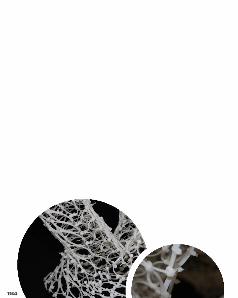
164
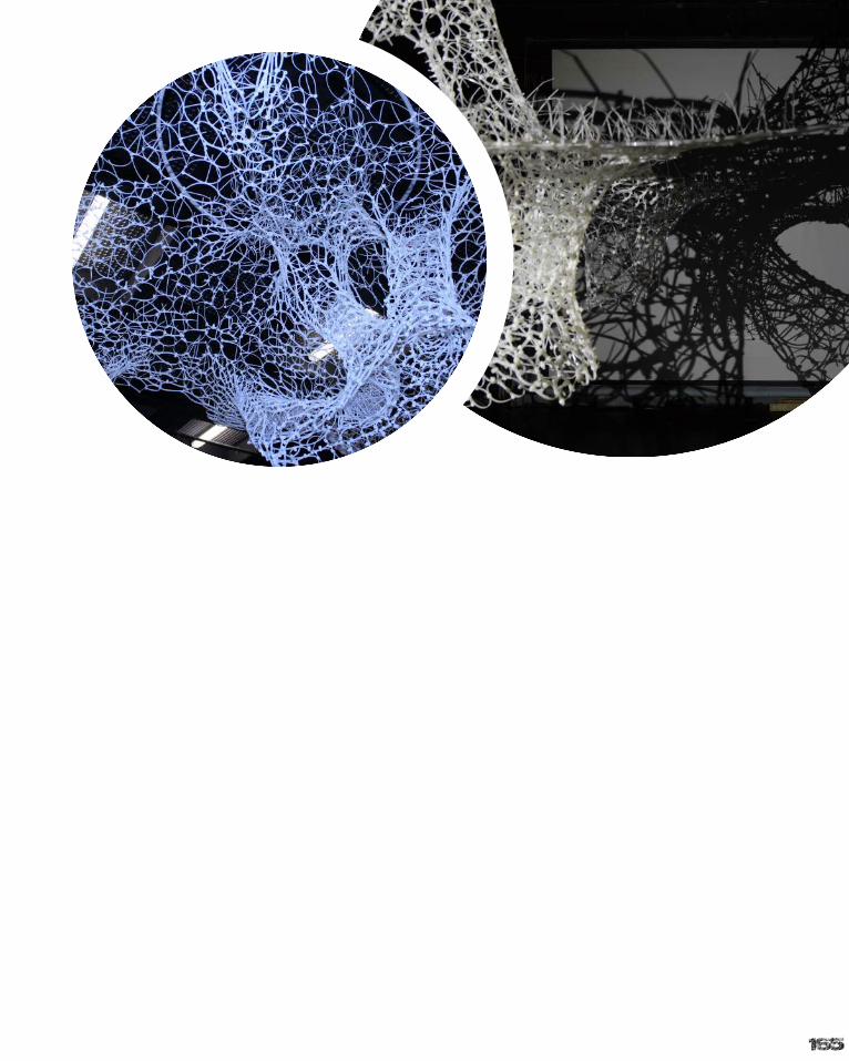
165
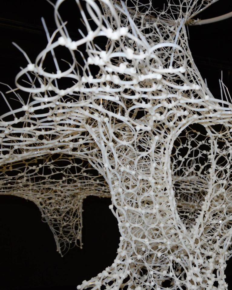
166
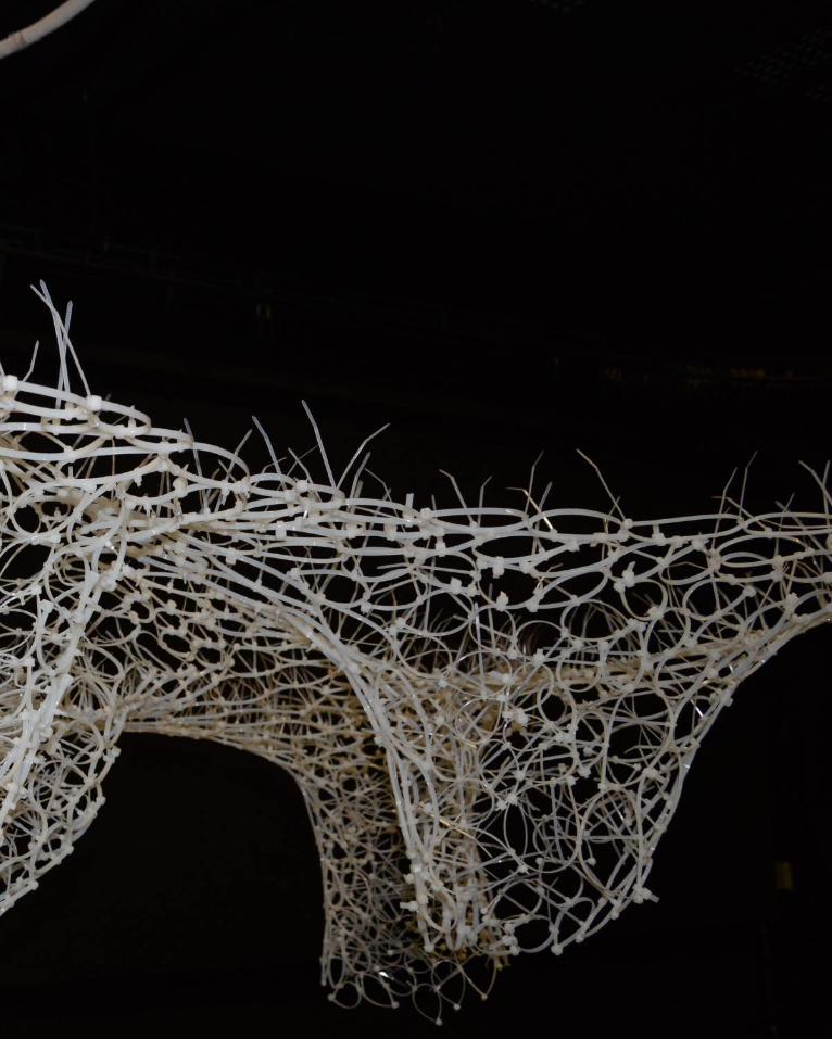
167
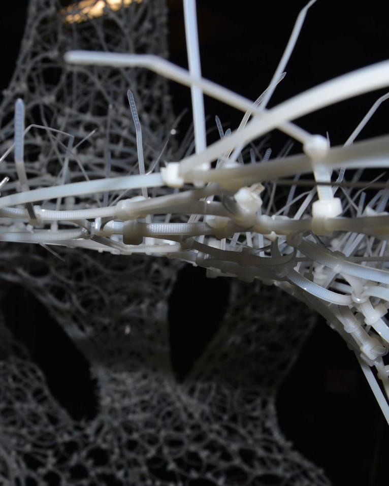
168
169
Part A addressed the fundamentals behind the subject and the building blocks for develop-ment. With the advent of Part B, much of the work has related more primarily back to the learning objectives sought out in the handbook and refer-ence to them is more easily noticed throughout the work in this section. Part C allowed the reali-sation of this semester’s work and the progress of techniques, lessons and skills gained through-out. Parametric modelling is now a key tool I will utilise in moving forward into the industry.
Objective 1 - With development towards an end result occurring in Part B, designs began to work towards outcomes that both explored the brief and our own personal interest. The tasks set, such as with the Green Void project, allowed the exploration and realisation of digital technolo-gies and in doing so allowed us to interrogate and develop the outlines of the brief through form finding and research.
Objective 2 - This objective was addressed in both the journal and the algorithmic activities. By providing case studies to explore and tutorials to follow, work related tasks were discovered to allow the development of multiple iterations. In doing so a well rounded view of the possibilities of these designs was established and better re-finement could occur for Part C development.
Objective 3 - Development of digital skills has grown exponentially over the course of the se-mester. Introduction to Grasshopper has al-lowed development of knowledge in this field and more refined research into case study proj-ects has seen expansion of this through the use of Kangaroo, lunchbox, weaverbird and other plug-in systems. Use of laser cutting was also a first as previous models had been developed through manual means. These skills will be use-ful in further development and external projects.
Objective 4 - The idea of air could simply mean something that floats above a surface, however through the exploration of techniques and the use of the Merri Creek, research into the inter-play between the environment, air and design have been better understood and resultant de-signs will follow.Objective 5 - Part B introduced us to projects and works that have succeeded in the built world. In doing so, our analysis and resultant develop-ment focused on proposing potential outcomes against real life projects. This provided us with the framework to propose our own conclusions and designs that were better researched and refined.
Objective 6 - Lectures, tutorials and previous subjects have given us the tools to look both analytically and critically at works that have suc-ceeded in real life. While being able to step back and look at a project with no emotional bias is a good skill, it is also important to be able to feel and appreciate what the site can offer on a hu-man level, rather than a professional one. These lessons have enabled us to look at precedent projects and our own designs and further devel-op them into more well rounded outcomes.
Objective 7 - Previous work in Rhino had been carried out in other subjects, however Grasshop-per and its external programs were a new sys-tem. By completing weekly tasks, understanding tutorials and lectures, and undertaking personal research, skills in these programs quickly de-veloped into something that can be applied to end result outcomes and potentially advance to a professional level into the future.
Objective 8 - In my transition through this se-mester, leans towards the tensile have meant that certain program areas be focused on a pursued. In doing this a better understanding of these areas was obtained, however there is still an interest in the many other features that programs like Grasshopper can offer and further research and discovery will improve these skills into the future.

170

171
Algorithmic Sketchbook
Entries
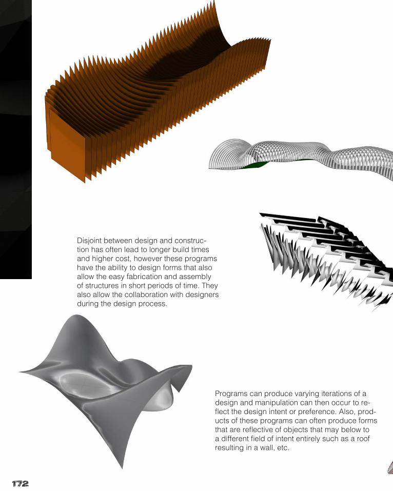
172
Programs can produce varying iterations of a design and manipulation can then occur to re-flect the design intent or preference. Also, prod-ucts of these programs can often produce forms that are reflective of objects that may below to a different field of intent entirely such as a roof resulting in a wall, etc.
Disjoint between design and construc-tion has often lead to longer build times and higher cost, however these programs have the ability to design forms that also allow the easy fabrication and assembly of structures in short periods of time. They also allow the collaboration with designers during the design process.
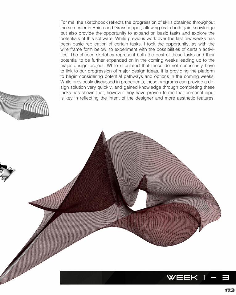
173
Week 1 - 3
For me, the sketchbook reflects the progression of skills obtained throughout the semester in Rhino and Grasshopper, allowing us to both gain knowledge but also provide the opportunity to expand on basic tasks and explore the potentials of this software. While previous work over the last few weeks has been basic replication of certain tasks, I took the opportunity, as with the wire frame form below, to experiment with the possibilities of certain activi-ties. The chosen sketches represent both the best of these tasks and their potential to be further expanded on in the coming weeks leading up to the major design project. While stipulated that these do not necessarily have to link to our progression of major design ideas, it is providing the platform to begin considering potential pathways and options in the coming weeks. While previously discussed in precedents, these programs can provide a de-sign solution very quickly, and gained knowledge through completing these tasks has shown that, however they have proven to me that personal input is key in reflecting the intent of the designer and more aesthetic features.
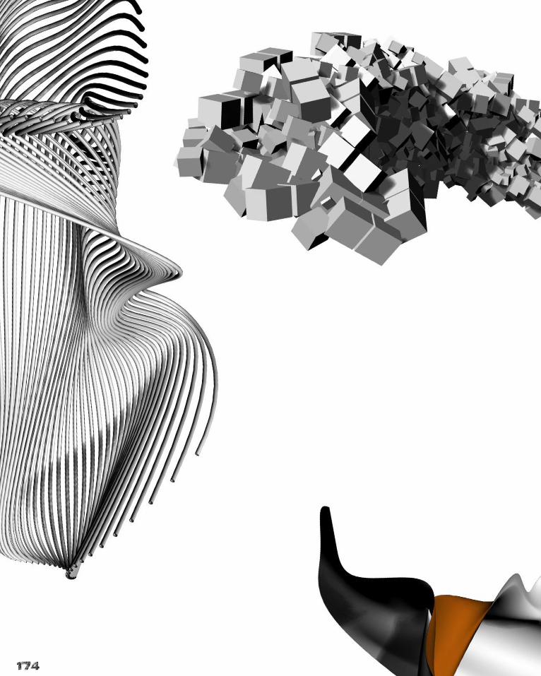
174
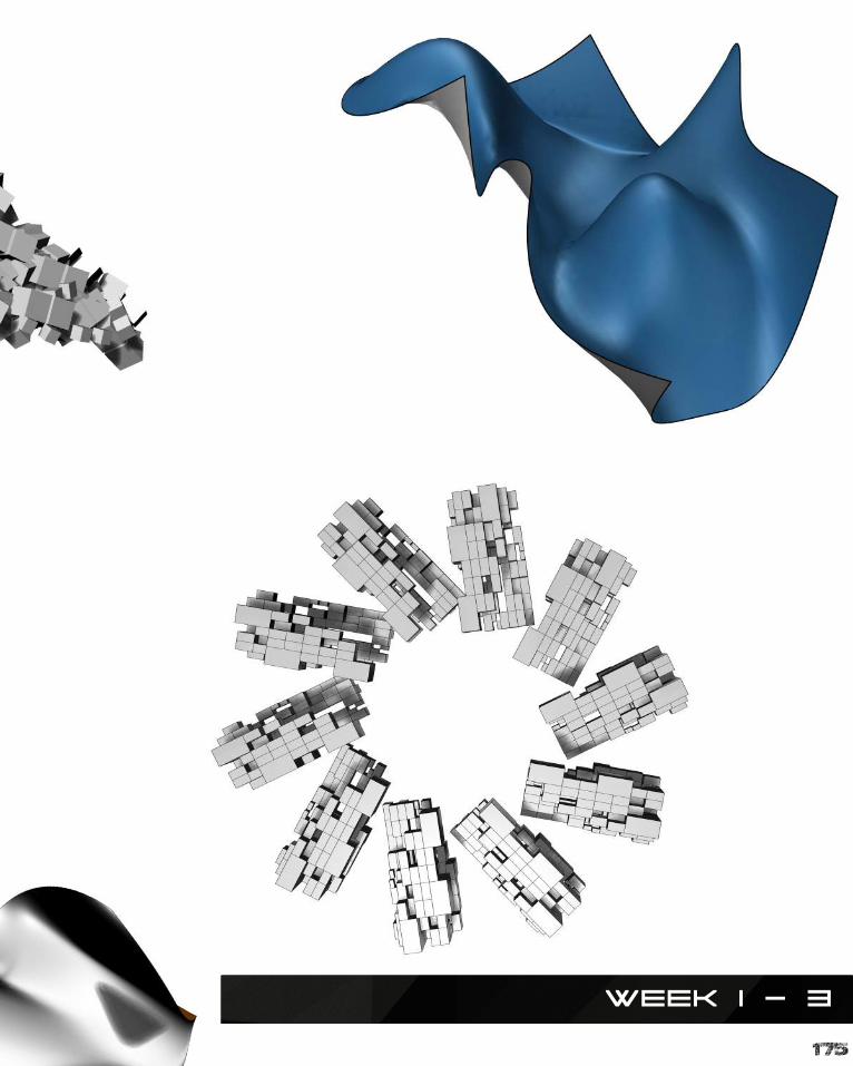
175
Week 1 - 3
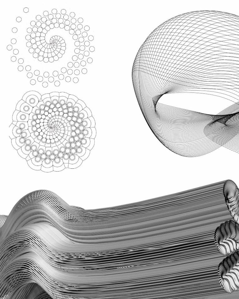
176
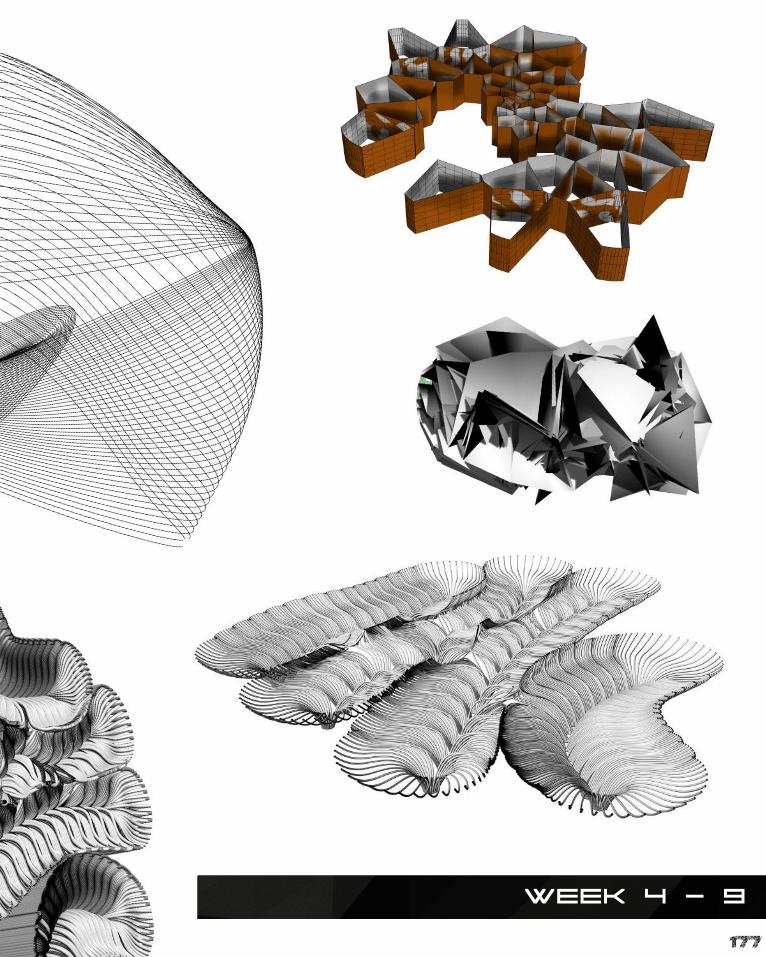
177
Week 4 - 9
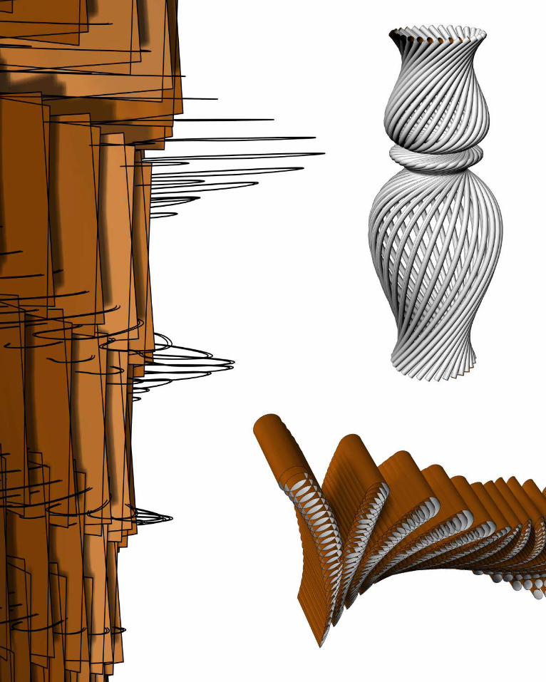
178

179
Week 4 - 9
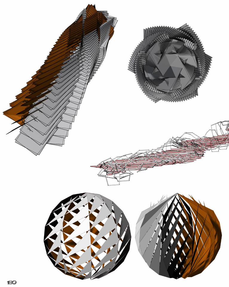
180

181
Week 4 - 9

182
References - Part A
TEXTS:
Amy Frearson, Carbon-Fibre Pavilion (2014) <http://www.dezeen.com/2014/06/26/icd-itke-pavilion-beetle-shells-university-of-stuttgart/> [accessed 12 March 2015].
Anthony Vidler, Review of Rethinking Architecture and the Anaesthetics of Architecture (United States: Harvard Design Magazine, 2000), p. 3 - 11.
Brady Peters, Computation Works: The Building of Algorithmic Thought from Architectural Design ([n.p.]: , 2013), p. 10.
Dan Howarth, Renzo Piano Design Glass “Organic Creature” to house Pathe Foundation (2014) <http://www.dezeen.com/2014/06/04/renzo-piano-pathe-foundation-paris/> [accessed 11 March 2015].
Fast Co Design, Shaped By Algorithms, A Solar Powered Pavilion That Soaks Up Maximum Rays (2012) <http://www.fastcodesign.com/1670678/shaped-by-algorithms-a-solar-powered-pavilion-that-soaks-up-maxi-mum-rays> [accessed 16 March 2015].
Institute For Advanced Architecture, Endesa Pavilion & Research Projects (2009) <http://www.iaac.net/projects/endesa-pavilion-25> [accessed 17 March 2015].
Kostas Terzidis, Algorithmic Architecture (Great Britain: Elsevier, 2006), p. 11.
Lian Hurst Mann, Reconstructing Architecture: Critical Discourses and Social Practices, ed. by Thomas A. Dut-ton, Illustrated edn (Minnesota: U of Minnesota Press, 1996), p. 1.
NBBJ, A City Blossoms (2015) <http://www.nbbj.com/work/hangzhou-stadium/> [accessed 15 March 2015].
Renzo Piano Building Workshop, Pathe Foundation (2014) <http://www.rpbw.com/project/81/pathe-foundation/> [accessed 10 March 2015].
Seoul Design Foundation, Introduction of Dongdaemun Design Plaza & Park (2012) <http://www.seouldesign.or.kr/eng/plaza/concept.jsp> [accessed 11 March 2015].
SHoP Architects, The Porter House (2015) <http://www.shoparc.com/project/The-Porter-House> [accessed 10 March 2015].
Universitat Stuttgart, ICD/ITKE Research Pavilion 2013-14 (2015) <http://icd.uni-stuttgart.de/?p=11187> [ac-cessed 11 March 2015].
Zaha Hadid Architects, Dongdaemun Design Plaza (2015) <http://www.zaha-hadid.com/architecture/dongdae-mun-design-park-plaza/?doing_wp_cron> [accessed 12 March 2015].

183
IMAGES:
Adria Goula, Endesa Pavilion (2011) <http://www.archdaily.com/274900/endesa-pavilion-iaac/> [accessed 14 March 2015].
Amy Frearson, Dongdaemun Design Plaza (2014) <http://www.dezeen.com/2014/03/23/zaha hadid-dongdaemun-design-plaza-seoul/> [accessed 16 March 2015].
ArchDaily, NBBJ and CCDI Break Ground on Hangzhou Sports Park (2015) <http://www.archdaily.com/56594/nbbj-and-ccdi-break-ground-on-hangzhou-sports-park/> [accessed 17 March 2015].
Architecture View, Dongdaemun Design Plaza (2011) <http://architecture-view.com/category/store/> [accessed 18 March 2015].
Autodesk, Botswana Innovation Hub (2015) <http://pdf.directindustry.com/pdf/autodesk/revit/14521-322291.html> [accessed 17 March 2015].
Bara Bild, Endesa Pavilion (2015) <http://www.barabild.se/arkitekturfotograf/endesa-pavilion> [accessed 17 March 2015].
Christopher Jobson, Pathe Foundation Headquarters (2015) <http://www.thisiscolossal.com/2014/06/the-new-pathe-foundation-headquarters-by-renzo-piano-squeezed-into-a-city-block-in-paris/> [accessed 13 March 2015].
Divisare, Pathe Foundation (2014) <http://divisare.com/projects/268939-Renzo-Piano-Building-Workshop-Path-Foundation> [ac-cessed 13 March 2015].
HDW, Geometric Shapes (2011) <http://hdw.eweb4.com/wallpapers/2414/> [accessed 12 March 2015].
HDW, Skyscraper Ecosystem (2015) <http://imgkid.com/organic-architecture-skyscrapers.shtml> [accessed 11 March 2015].
John Hopewell, Pathe Foundation Headquarters (2014) <http://variety.com/2014/film/news/jerome-seydoux-pathe-foundation-bows-to-get-go-success-1201333302/> [accessed 12 March 2015].
Michel Denance, Pathe Foundation (2014) <http://divisare.com/projects/268939-Renzo-Piano-Building-Workshop-Path-Foundation/images/4682114> [accessed 12 March 2015].
NBBJ, A City Blossoms (2015) <http://www.nbbj.com/work/hangzhou-stadium/> [accessed 14 March 2015].
Preservation Lovin, The Porter House (2003) <http://preservationlovin.tumblr.com/post/4731315245/porter-house-with-architect-gregg-pasquarelli-of> [accessed 9 March 2015].
Scott Moore, The Porter House (2007) <https://www.flickr.com/photos/wizum/1408962837/> [accessed 9 March 2015].
SHoP Architects, The Porter House (2015) <http://www.shoparc.com/project/The-Porter-House> [accessed 11 March 2015].
Superb Wallpapers, White Cubes (2012) <http://www.superbwallpapers.com/3d/white-cubes-15427/> [accessed 11 March 2015].
Universitat Stuttgart, ICD/ITKE Research Pavilion 2013-14 (2015) <http://icd.uni-stuttgart.de/?p=11187> [accessed 12 March 2015].
Universitat Stuttgart, ICD/ITKE Research Pavilion 2013-14 (2015) <http://icd.uni-stuttgart.de/?p=9697> [accessed 12 March 2015].
Virgile Simon Bertrand, Dongdaemun (DDP), Seoul, South Korea (2015) <http://www.designbuild-network.com/projects/dongdae-mun-design-plaza-ddp-seoul/dongdaemun-design-plaza-ddp-seoul2.html> [accessed 15 March 2015].
Zaha Hadid Architects, Dongdaemun Design Plaza (2015) <http://www.zaha-hadid.com/architecture/dongdaemun-design-park-plaza/> [accessed 13 March 2015].

184
TEXTS:
Anuradha Chatterjee, ‘Green Void’, Architecture Australia, May/June, (2009), 2, in <http://www.sydneycustoms-house.com.au/news/documents/GreenVoidArchitectureAustraliap25-MayJun09.pdf> [accessed 7 May 2015].
Canton Tower, Canton Tower (2015) <http://www.cantontower.com/en/> [accessed 11 April 2015].
Ceres Inc., Ceres Environmental Park (2012) <http://www.ceres.org.au/> [accessed 21 April 2015].
Council on Tall Buildings and Urban Habitat, Canton Tower (2015) <http://skyscrapercenter.com/building/can-ton-tower/9385> [accessed 11 April 2015].
Friends of Merri Creek, Merri Creek (2014) <http://www.friendsofmerricreek.org.au/> [accessed 23 April 2015].
LAVA, Green Void (2015) <http://www.l-a-v-a.net/projects/green-void/> [accessed 7 April 2015].
Lydra Group, Melbourne Laser Cutter (2014) <http://melbournelasercutter.com.au/> [accessed 22 April 2015].
Matsys Design, Gridshell (2015) <http://matsysdesign.com/tag/gridshell/> [accessed 2 April 2015].
Merri Creek Management Committee, About Merri Creek (2015) <http://www.mcmc.org.au/index.php?option=com_content&view=article&id=36:about-merri-creek&Itemid=188> [accessed 24 April 2015].
Moreland City Council, Creek Trails (2015) <http://www.moreland.vic.gov.au/parks-pools-sport/discover-our-creek-trails.html> [accessed 27 April 2015].
SJET, Voltadom (2011) <http://sjet.us/MIT_VOLTADOM.html> [accessed 5 April 2015].
SmartGeometry, Gridshell Digital Tectonics (2013) <http://smartgeometry.org/index.php?option=com_content&view=article&id=134%3Agridshell-digital-tectonics&catid=44&Itemid=131> [accessed 4 April 2015].
The World Federation of Great Towers, Canton Tower (2012) <http://www.great-towers.com/towers/canton-tow-er/> [accessed 12 April 2015].
Zeal 3D Printing Services, 3D Printing (2015) <http://www.zeal3dprinting.com.au/> [accessed 21 April 2015].
PART C
Australian Government, BOM Weather (2015) <http://www.bom.gov.au/> [accessed 2 June 2015].
Victorian Government, Melbourne Water (2015) <http://www.melbournewater.com.au/Pages/home.aspx> [accessed 2 June 2015].
References - Part B

185
IMAGES:
AECCafé, Voltadom by Skylar Tibbits (2012) <http://www10.aeccafe.com/blogs/arch-show-case/2012/06/20/voltadom-by-skylar-tibbits/> [accessed 8 May 2015].
Canton Tower, Bubble Tram (2015) <http://www.cantontower.com/en/Sightseeing.aspx?code=0302> [ac-cessed 20 May 2015].
Detail Inspiration, Canton Tower in Guangzhou (2010) <http://www.detail-online.com/inspiration/canton-tower-in-guangzhou-103502.html> [accessed 15 May 2015].
Google Inc., Google Earth Images (2015) <https://www.google.com/earth/> [accessed 28 May 2015].
LAVA, Green Void (2015) <http://www.l-a-v-a.net/projects/green-void/> [accessed 12 May 2015].
Made in China, Dongguan Glory Star Laser Technology Co., Ltd. (2015) <http://glorystarlaser.en.made-in-china.com/product-group/AMxQbNYcYTVs/CO2-Laser-Cutting-And-Engraving-Machine-catalog-3.html> [accessed 27 May 2015].
Matsys Design, 2012 Gridshell (2015) <http://matsysdesign.com/category/projects/sg2012-gridshell/> [ac-cessed 6 May 2015].
Shafir, Canton Tower (2012) <china~guangzhou~volume_2~canton_tower_1.htm> [accessed 14 May 2015].
SJET, Voltadom (2011) <http://sjet.us/MIT_VOLTADOM.html> [accessed 8 May 2015].
Traffic Jam, Canton Tower (2012) <http://stuckintrafficjam.com/2012/11/17/made-in-china-places-and-fac-es-photoblog/2_canton-tower-guangzhou/> [accessed 12 May 2015].
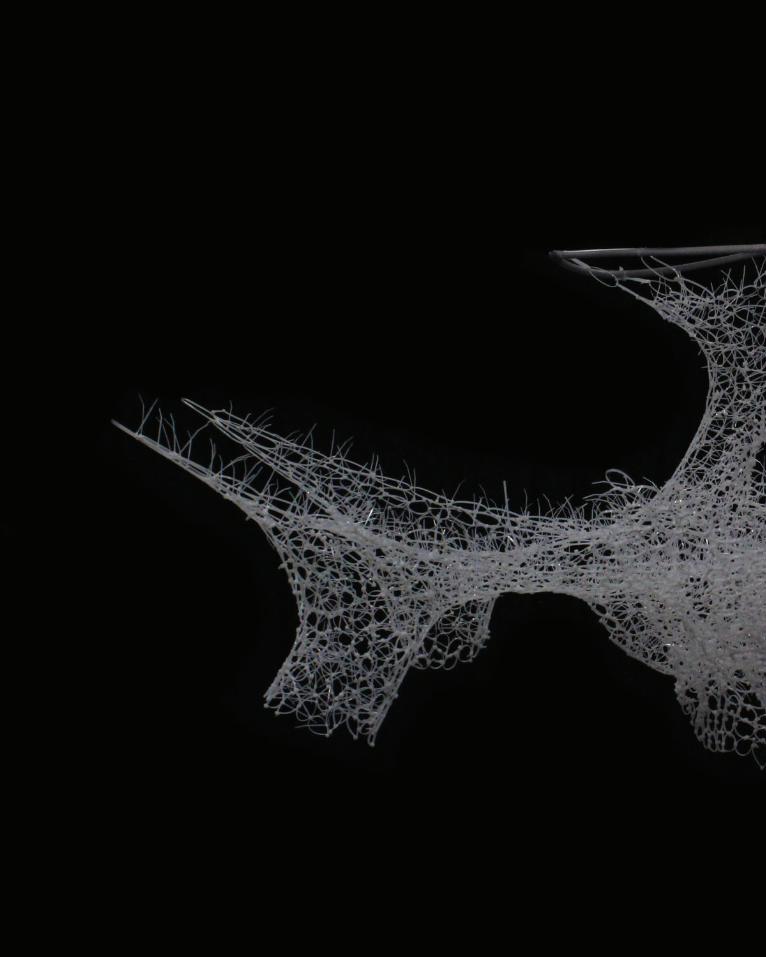
186
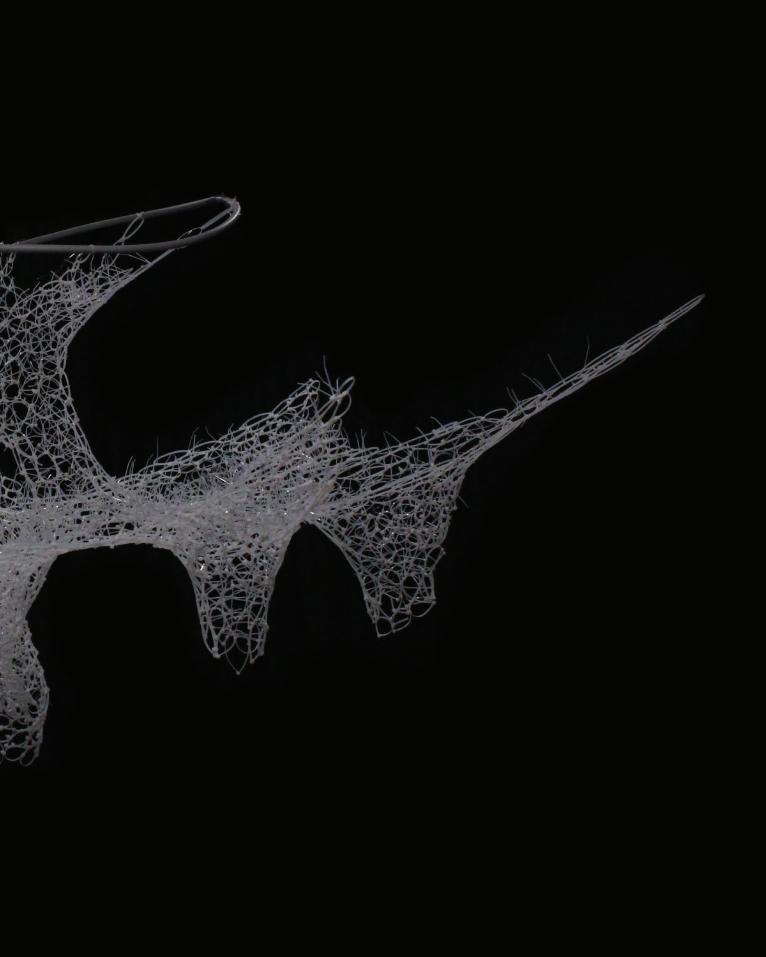
187

188