Embed Size (px)
Citation preview
Damping Performance of Dynamic VibrationAbsorber in Nonlinear Simple Beam with 1:3Internal ResonanceYi-Ren WangDepartment of Aerospace Engineering, Tamkang University, NewTaipei City, Tamsui Dist., 25137, Taiwan.
Hsueh-Ghi LuRD Center-Environmental Reliability QA Div., Enterprise Products Testing Department, Pegatron Corporation,Taipei City 11261, Taiwan.
(Received 20 October 2014; accepted 17 November 2016)
This study investigated the damping effects of a dynamic vibration absorber (DVA) attached to a hinged-hingednonlinear Euler-Bernoulli beam. The model constructed in this study was used to simulate suspended nonlinearelastic beam systems or vibrating elastic beam systems on a nonlinear Winkler-type foundation. This makesthe modeling in this study applicable to suspension bridges, railway tracks, and even carbon nanotubes. Thehinged-hinged beam in this study includes nonlinear stretching effects, which is why we adopted the methodof multiple scales (MOMS) to analyze the frequency responses of fixed points in various modes. The use ofamplitudes and vibration modes made it possible to examine the internal resonance. Our results indicate thatparticular elastic foundations or suspension systems can cause 1:3 internal resonance in a beam. The use of 3Dmaximum amplitude contour plots (3DMACPs) enabled us to obtain a comprehensive understanding of variousDVA parameters, including mass, spring coefficient, and the location of DVA on the beam, and thereby combinethem for optimal effect. Our results were verified using numerical calculations.
1. INTRODUCTION
Engineering from the scale of small mechanical componentsto that of aircraft wings and bridges must take into accountthe effects of vibration, which can cause fatigue, loosening ofparts, and failure. Vibration can be linear or nonlinear, withthe latter involving internal resonance that is complex and dif-ficult to analyze. As described by Nayfeh and Mook,1 in theevent that the natural vibration frequencies of various degreesof freedom (DOFs) are multiples of one another, excitationat high frequencies can increase amplitudes at low frequen-cies. This study sought to account for this unique nonlinearphenomenon. Nayfeh and Balachandran2 defined several sta-ble conditions in nonlinear systems and presented a numberof methods that could be used to determine system stability,and are therefore highly valuable as a reference in the anal-ysis of system stability. Nayfeh and Pai3 investigated vibra-tions in nonlinear Euler-Bernoulli beams. According to New-ton’s laws, Euler’s angle transformation, and the Karman-typestrain-displacement relationship in order to derive 3D and 2Dequations associated with nonlinear beams. These theoreti-cal models have greatly benefited related research. Nayfehand Mook1 also proposed a number of methods with whichto solve nonlinear systems, including the Poincare method, theLindstedt method, the average method, and MOMS, which ishighly conducive to the analysis of damped vibration systems.Ji and Zu4 studied the rotating shaft system of a Timoshenkobeam using MOMS to analyze the natural frequency responsesof nonlinear systems. Nayfeh and Nayfeh5 employed MOMSto identify nonlinear modes and nonlinear frequencies, where-
upon they applied the Galerkin method to the analysis of dy-namic responses in a nonlinear beam. Analysis of vibrationsin an elastic beam involves many factors. Van Horssen andBoertjens6 considered a suspension bridge under the influenceof nonlinear aerodynamic effects using the theoretical modelof a Euler-Bernoulli beam with linear springs to simulate vi-brations in the bridge. They discovered that energy can shiftbetween the first and third modes and that this is typical of non-linear internal resonance. Their study prompted a great dealof research based on theoretical models. Theories similar tothis, in which a beam is placed on an elastic foundation, havebeen widely applied to civil, mechanical, and aerospace engi-neering, by researchers such as Mundrey.7 Fu et al.8 reportednonlinear vibrations in embedded carbon nanotubes (CNTs),based on research involving the use of nonlinear 2D Euler-Bernoulli beams to simulate vibrations in CNTs on elastic ma-trices. Shen9 used the model of a nonlinear 2D Euler-Bernoullibeam to analyze vibrations in a post-buckling beam placed on adouble-layered elastic foundation, thereby demonstrating thatthe stiffness of elastic foundations has a significant influenceon the vibration behavior of nonlinear beams.
Wang and Chen10 developed a damping approach to vibra-tion reduction without the need to change the damper, butmerely enable its relocation by having a mass-spring-dampervibration absorber hung from the optimal damping location ona rotating mechanism (a CD-ROM drive or the coupling sys-tem of rotary wings and swashplates). Wang and Chang11 stud-ied nonlinear vibrations in a rigid plate using cubic springsto simulate supports at the four corners with two single-mass dampers hung from beneath the plate. The locations
International Journal of Acoustics and Vibration, Vol. 22, No. 2, 2017 (pp. 167–185) https://doi.org/10.20855/ijav.2017.22.2462 167

Y.-R. Wang, et al.: DAMPING PERFORMANCE OF DYNAMIC VIBRATION ABSORBER IN NONLINEAR SIMPLE BEAM WITH 1:3 INTERNAL. . .
of the dampers were adjusted to achieve optimal damping ef-fects. Dynamic vibration absorber (DVA) is a practical passivedamping device for vibrating systems. For a linear vibratingbeam, DVA can be pre-tuned to the modal frequency of thevibrating structure or the disturbance frequency to damp outthe beam vibration. Wang and Chang12 discussed a hinged-free linear Euler-Bernoulli beam placed on a nonlinear elas-tic foundation. They found that placing a DVA of appropriatemass could prevent internal resonance and suppress vibrationsin the beam. Nambu et al.13 studied the smart self-sensingactive DVA attached on a flexible beams supported string. Asmall cantilevered piezoelectric transducer was used to real-ize this active DVA. They showed improvement control ro-bustness upon passive DVAs. Tso et al.14 proposed a noveldesign method of hybrid dynamic vibration absorber (HVA) tosuppress broadband vibration of the whole structure instead ofjust one point of the structure. Samani and Pellicano15 identi-fied the optimal locations of a DVA applied to a simple beamsubjected to regularly spaced and concentrated moving loads.The nonlinear stiffness of a nonlinear DVA possesses com-plex dynamic properties such as quasi-periodic, chaotic, andsub-harmonic responses. They discovered that the dampingeffects of a nonlinear non-symmetric dissipation DVA are su-perior to those of a linear DVA. In contrast, Wang and Lin16
used internal resonance contour plots (IRCPs) and flutter speedcontour plots (FSCPs) to analyze nonlinear dynamic stability.Their results demonstrated that changing the location of thedamper can prevent internal resonance and inhibit vibrationsin the main body. Wang and Kuo17 examined the vibrationsof a hinged-free nonlinear beam placed on a nonlinear elasticfoundation. The 1:3 internal resonance in the first and secondmodes of the beam was found. An optimal location of an at-tached DVA was proposed to prevent internal resonance andsuppress vibrations. Wang and Tu18 investigated the damp-ing effects of a tuned mass damper (TMD) on a fixed-free 3Dnonlinear beam resting on a nonlinear elastic foundation withexisting internal resonances. They proposed that the locationsof the maximum amplitudes between node points in the modeshapes and near the free end of the beam display the best damp-ing effect for the fixed-free 3D beam. In the works of Wangand Kuo17 and Wang and Tu,18 the nonlinear geometry andnonlinear inertia were included in these two nonlinear beams.The conditions to trig the internal resonance were also inves-tigated in their researches. The various beam boundary condi-tions were examined for better understanding the DVA damp-ing effects on beam vibrations. Wang and Liang19 investigatedthe damping effects of vibration absorbers with a lumped masson a hinged-hinged beam. This kind of vibration absorber isable to mitigate vibrations in mechanical or civil engineeringstructures on an elastic foundation; however, they are not ap-plicable to all suspension systems. It is this shortcoming thatwe sought to address in this research.
Further consideration of resonance analysis of structures us-ing the analytical and numerical strategies can be found in thework of Ansari et al.20 They derived a geometrically nonlinearbeam model to simulate the nanobeam vibration under ther-mal environment. The material properties of nanobeams varythrough the thickness direction with functionally graded (FG)distribution. The method of multiple scales was applied to de-
termine the frequency response of the temperature and materialproperties. A 2-DOF nonlinear system (the main body and thecontroller (absorber)) with quadratic and cubic nonlinearitiesunder external and parametric bounded excitations was con-sidered in the work of Sayed and Kamel.21 The method ofmultiple scales was applied to determine the amplitudes andphases in the existence of internal resonance. The stabilityof the controlled system was studied. Ghayesh et al.22 in-vestigated the axially moving beam with a three-to-one inter-nal resonance. The coupled longitudinal and transverse dis-placements of the beam were studied numerically. The fre-quency response of the nonlinear forced system was solvedby the pseudo-arc length continuation method and direct timeintegration. Ghayesh and Amabili23 provided a detailed dis-cussion of an axially moving Timoshenko beam with an inter-nal resonance. They used the Galerkin’s scheme to discretizethe nonlinear partial differential equations into a set of non-linear ordinary differential equations. The pseudo-arc lengthcontinuation method was also employed to find the frequencyresponse of the nonlinear forced system. The dynamic and res-onant response were examined by the Poincare maps. Stabil-ity properties with and without internal resonance were pre-sented. Ansari et al.24 investigated the forced vibration ofnonlinear magneto-electro-thermo elastic (METE) nanobeams.The Galerkin technique was applied to obtain a time-varyingset of ordinary differential equations. The pseudo-arc lengthcontinuum scheme was also used to solve this nonlinear beamsystem. Ansari et al.25 applied the similar numerical strategiesin the analysis of the forced vibration behavior of reinforcedsingle-walled carbon nanotubes (SWCNTs). Different effectsof SWCNT parameters were examined by the frequency re-sponses. Their results showed that the amplitude peak reduceswhen the nanotube volume fraction or dimensionless dampingparameter gets larger. Ansari et al.26 also invested the sur-face stress effect on the vibrations of nanobeams. The general-ized differential quadrature method and the shifted Chebyshev-Gauss-Lobatto grid points were employed to solve the nonlin-ear problem. The frequency response of nanobeams includingthe effect of surface stress was investigated. Ansari et al.27
performed a numerical study of two-phase BiTiO3-CoFe2O4
composites nanobeams subjected to various boundary condi-tions. The Galerkin and pseudo arc-length methods were em-ployed for solving nonlinear problems. They also provided anovel technique of periodic time differential operators for thetime domain discretization. Ansari and Gholami28 further in-vestigated the surface stress and surface inertia effects on therectangular nanoplates. The equations of motion were solvednumerically for the rectangular Si and Al nanoplates with vari-ous boundary supports by means of the generalized differentialquadrature method. The hardening nonlinearity and surface ef-fects showed considerable influences on nanoplates.
This study considered a nonlinear hinged-hinged Euler-Bernoulli beam supported or suspended using nonlinearsprings, including internal resonance and the coupling of mul-tiple modes. This system is able to simulate a vibrating me-chanical system suspended or placed on an elastic medium,such as a suspension bridge or the tracks of subways or high-speed trains. This system can also be used to simulate CNTsplaced on an elastic matrix. The main body in this study was
168 International Journal of Acoustics and Vibration, Vol. 22, No. 2, 2017

Y.-R. Wang, et al.: DAMPING PERFORMANCE OF DYNAMIC VIBRATION ABSORBER IN NONLINEAR SIMPLE BEAM WITH 1:3 INTERNAL. . .
(a)
(b)
(c)
Figure 1. A schematic of the hinged-hinged beam system, (a) suspension beam, (b) Winkler type foundation, (c) relationship between beam displacement androtation angle.
subjected to a harmonic force. We used a mass-spring DVAto reduce vibrations, taking into account the effects of stretch-ing. The influence of parameters, such as the mass, elasticitycoefficient, and location of the DVA on damping performancewere analyzed extensively. We used 3D maximum amplitudecontour plots (3DMACPs) to identify the optimal combinationof parameters as well as numerical calculations to verify theaccuracy of the results.
2. DEVELOPMENT OF THE THEORETICALMODEL
The main body in this study comprised of a nonlinear elasticbeam supported or suspended by nonlinear springs to simulatean elastic foundation or suspension cables. Figure 1 illustratesthe coordinate system, wherem denotes the mass of the elasticbeam per unit length; A, E, and IA are the cross-section area,Young’s modulus, and moment of inertia of the beam, respec-tively; k is the liner spring constant of the elastic foundation; βsignifies the nonlinear spring constant; µ is the linear dampingcoefficient of the beam; and fs and gs denote the linear springconstant and the damping coefficient of the DVA, respectively.
2.1. Deduction and Non-Dimensionalizationof Nonlinear Equations of Motion
Figures 1a and 1b exhibit the hinged-hinged nonlinear beamemployed in this study. We referred to the nonlinear beam the-ory proposed by Nayfeh and Pai9 and used Newtonian’s Laws
to develop a complete model including the elastic foundationand the DVA. We first considered the initial status of the beamwhen it is straight and assumed that each cross-section is aplane that follows the stress-strain laws. According to Nayfehand Pai9 and from Fig. 1c, the axial strain e and the rotation an-
gle θ are related to u′ and W′
as e =
√(1 + u′)2 +W
′2 − 1,
cos θ = (1 + u′)/(1 + e), and sin θ = W′/(1 + e). As-
suming u and W are small but finite, then e and θ can befurther expanded as e = u′ + W
′2/2 − (u′W
′2)/2 . . . and
θ = tan−1(W′/(1 + u′)) = W
′ − u′W ′ + u′2W′+ u′2W
′ −W′3/3 . . . . Using Newton’s Laws, Euler’s angle transforma-
tion, and Taylor series expansion, we obtained the basic equa-tions of motion for the nonlinear beam. We excluded any ro-tations in the beam, limiting it to planar motions. Thus, theequations of motion for the 2D beam are as follows:
mu− EAu′′ = EA
(1
2W′2 − u′W ′2
)′+
EIA
[W′ (W′′′ − u′′′W ′ − 2u′′W
′′ − 3u′W′′′)]′
; (1)
mW − EIAWiv
= EA
(u′W
′ − u′2W ′ + 1
2W′3)′
+
EIA
[u′W
′′′+(u′W
′)′′ − (u′2 −W ′2)W ′′′ −u′(u′W
′)′′ − (u′2W ′ − 1
3W′3)′′ ]′
; (2)
International Journal of Acoustics and Vibration, Vol. 22, No. 2, 2017 169

Y.-R. Wang, et al.: DAMPING PERFORMANCE OF DYNAMIC VIBRATION ABSORBER IN NONLINEAR SIMPLE BEAM WITH 1:3 INTERNAL. . .
where ( )′ and (˙) denote d/dx and d/dt, respectively. Theu and W represent the beam displacement in the longitudinaldirection (x-axis) and transversal direction (vertical-axis), re-spectively. The system considered in this study is a slenderelastic beam; therefore, the longitudinal inertia force mu inEq. (1) can be disregarded. The beam is hinged at both ends,and no longitudinal forces were imposed. This made it neces-sary to consider the effects of stretching. The boundary condi-tions are as follows:
u(0, t) = 0; u(l, t) = 0; W (0, t) = 0;
W (l, t) = 0; W′′(0, t) = 0; W
′′(l, t) = 0. (3)
From Eq. (1), we can express the u′′ as
u′′ = −(
1
2W′2)′
+ . . . . (4)
The integral of Eq. (4) is
u′ = −1
2W′2
+ c1(t);
u = −1
2
∫ l
0
W′2dx+ c1(t)x+ c2(t). (5)
Substituting Eq. (5) into the boundary conditions in Eq. (3)produces
c2(t) = 0; c1(t) =1
2l
∫ l
0
W′2dx. (6)
After substituting Eqs. (5) and (6) into Eq. (2), we can simplifythe equations of motion to an equation in which vibrations arepresented in theW direction. We included the structural damp-ing term µW of the elastic beam, the linear and nonlinear elas-tic terms k[W + βW
3] of the support or suspension springs,
and the uniform distributed load F = FeiΩt , where µ is thestructural damping coefficient; k and β represent the linear andnonlinear elastic constant of the support or suspension springs,respectively. The hanging DVA was regarded an external forcefs[W (x, t)−WD]+gs[W (x, t)−WD] δ[x−lD], where fsand gs denote the spring constant and the damping coefficientof the DVA, respectively. It is also noted that l represents thebeam length and the WD and lD represent the displacementand the location of the DVA, respectively. We used Newton’slaws to deduce the equation of motion before reorganizing andnondimensionalizing it, thereby obtaining the following:
∗∗W +W iv + ω2W + µ
∗W +KW 3 +
k[W (x, τ)−WD
]+
λ[ ∗W (x, τ)−
∗WD
]δ[x− lD] =
1
2A
[∫ l
0
W ′2dx
]W ′′ + FeiΩτ . (7)
The boundary conditions in Eq. (3) are thus
W (0, τ) = 0; W ′′(0, τ) = 0;
W (l, τ) = 0; W ′′(l, τ) = 0. (8)
The non-dimensionalized equation of motion of the DVA is
m0
∗∗WD(τ)−
[k(u) + λ(
∗u)]
= 0; (9)
whereu(τ) = W (lD, τ)−WD(τ). (10)
Equation (7) is the non-dimensionalized equation of motion ofthe main body, in which ( )′ and (∗) represent d/dx and d/dτ ;ω2 is the ratio between the linear elasticity coefficient of thesupport or suspension springs and the elasticity coefficient ofthe elastic beam; µ is the non-dimensionalized beam dampingcoefficient; K is the ratio between the nonlinear vibration fre-quency of the supports or suspension springs and the vibrationfrequency of the elastic beam, lD is the non-dimensionalizedDVA position, A is the non-dimensional beam rigidity; and kand λ are the non-dimensionalized spring constant and damp-ing coefficient of the DVA, respectively. Appendix 1 containsthe definitions of the other non-dimensionalized coefficients.
2.2. Application of MOMSThis study adopted MOMS to analyze the frequency re-
sponse and fixed points of the nonlinear equation, whichinvolves dividing the time scale into fast and slow timescales. Suppose T0 is the fast-time term, T1, T2, . . . arethe slow-time terms, and W (x, τ, ε) = W0(x, t0, t1, . . .) +εW1(x, t0, t1, . . .), where ε is the time scale of small distur-bances and is an infinitesimal value. We also considered thedamping and nonlinear terms as well as the external force assmall disturbance terms and set the order at ε1 to facilitate anal-ysis. We substituted these principles into Eq. (7) and disre-garded the influence of high-order terms such as ε2, ε3, . . . onthe system. The terms of ε0 are as follows:
∂2W0
∂T 20
+∂4W0
∂x4+ ω2W0 = 0. (11)
The terms of ε1 are as follows:
∂2W1
∂T 20
+∂4W1
∂x4+ ω2W1 =
∂2W0
∂x2A
[1
2
∫ 1
0
(∂W0
∂x
)2
dx
]+
F −[k(u) + λ(
∗u)]δ[x− lD]− 2
∂2W0
∂T0∂T1−
µ∂W0
∂T0−KW 3
0 . (12)
The boundary conditions corresponding to ε0 and ε1 equationsare as follows: W (0, τ) = 0, W ′′(0, τ) = 0, W (l, τ) = 0,W ′′(l, τ) = 0. Considering that the DVA is linear, MOMSneed not be used to divide the time scale, such that only ε0 isconsidered in the DVA equation of motion.
3. ANALYSIS OF INTERNAL RESONANCECONDITIONS
3.1. Equation of Motion for the NonlinearBeam Without DVA
The process of modeling the system without the DVA is thesame as the development of the theoretical model in Section 2.Thus, we only provide a brief description below.
170 International Journal of Acoustics and Vibration, Vol. 22, No. 2, 2017
Y.-R. Wang, et al.: DAMPING PERFORMANCE OF DYNAMIC VIBRATION ABSORBER IN NONLINEAR SIMPLE BEAM WITH 1:3 INTERNAL. . .
After dropping the DVA from the equation of motion in theprevious section, we obtain the following:
∗∗W +W iv + ω2W =
1
2A
(∫ l
0
W ′2dx
)W ′′ − µ
∗W −KW 3 + FeiΩτ. (13)
In this model, the two ends are hinged; therefore, the boundaryconditions are
W (0, τ) = 0; W ′′(0, τ) = 0;
W (l, τ) = 0; W ′′(l, τ) = 0. (14)
Note that in this non-dimensionalized circumstance, l = 1.
3.2. Conditions of Internal Resonance in theBeam System without DVA
We applied MOMS and the terms comprising ε0 are as fol-lows:
∂2W0
∂T 20
+∂4W0
∂x4+ ω2W0 = 0. (15)
Terms comprising ε1 are as follows:
∂2W1
∂T 20
+∂4W1
∂x4+ ω2W1 =
1
2A∂2W0
∂x2
[∫ 1
0
(∂W0
∂x
)2
dx
]+
F − 2∂2W0
∂T0∂T1− µ∂W0
∂T0−KW 3
0 . (16)
Suppose that the general solution to W (x, τ) is
W (x, τ) =(A(T1)e−iζeiωT0 +A(T1)eiζe−iωT0
)φ(x); (17)
where ζ is the phase angle. Also, let
φ(x) = E1 sin γx+ E2 cos γx+ E3 sinh γx+ E4 cosh γx.(18)
By substituting the equation above into the boundary condi-tions, we obtain the eigenvalues γn = nπ/l, n = 1, 2, 3, . . . ,and l = 1, whereas the mode shape φn(x) can be expressed asφn(x) = sin γnx. After using orthogonal method, W0n(x, τ)can be written as
W0n(x, τ) =∞∑n=1
(Bn(T1)e−iζneiωnT0 +Bn(T1)eiζne−iωnT0
)φn(x) =
∞∑n=1
ξ0n(τ)φn(x). (19)
Using the orthogonal method, we multiply Eq. (15) by φn(x)and integrate it from 0 to l (l = 1 (normalized)) and obtain∗∗ξ0m(τ) +
(γ4m + ω2
)ξ0m(τ) = 0; (20)
∗∗ξ1m(τ) +
(γ4m + ω2
)ξ1m(τ) =
− 1
2γ2mξ0mA
[∫ 1
0
( ∞∑p=1
γ2pξ
20p cos2γpx
)dx
]+
F
∫ 1
0φmdx∫ 1
0φ2mdx
− 2∂2ξ0m(τ)
∂T0∂T1− µ∂ξ0m(τ)
∂T0−
K∫ 1
0φ2mdx
∫ 1
0
( ∞∑i
ξ0iφi
)( ∞∑j
ξ0jφj
)( ∞∑k
ξ0kφk
)φmdx;
(21)
and set the natural frequencies of the various modes in thesystem as ωn =
√γ4m + ω2. To determine the existence of
internal resonance in the beam system, we must derive theω2 conditions capable of causing internal resonance. Amongthese conditions, Eq. (21) contains ξ0iξ0jξ0k, an infinite se-ries of nonlinear terms. This hinders the determination ofinternal resonance with ω2; therefore, we used the methodproposed by Van Horssen6 and followed the procedure de-scribed by Wang and Liang19 to derive the internal reso-nance conditions created by ω2. We first observe the inte-gration term
∫ 1
0φi(x)φj(x)φk(x)φm(x)dx on the right side
of Eq. (21), which is the orthogonal product of φm(x) andφi(x)φj(x)φk(x). Based on the orthogonal method, the inte-gration term in Eq. (21) may contribute to the secular termsif it does not equal 0 and m = ±i ± j ± k. Further-more, as the dominant term in φm(x) is sin γmx, we canonly observe whether ±γi ± γj ± γk equals γm in the prod-uct terms in
∫ 1
0φi(x)φj(x)φk(x)φm(x)dx in order to confirm
the existence of orthogonality before addressing the questionof whether the harmonic frequencies extending from the har-monic combination are secular terms. As γm = nπ > 0, wecan eliminate −γm = γi + γj − γk and −γm = γi − γj + γkfrom the possibilities in ±γm = ±γi ± γj ± γk. Since γm =γi+γj −γk, −γm = γi−γj −γk, and γm = γi−γj +γk aresimilar; therefore, we need only to discuss three combinations:γm = γi+γj +γk, γm = γi−γj−γk, and γm = γi+γj−γkfrom the possibilities in ±γm = ±γi ± γj ± γk. Further-more, in the product ξ0iξ0jξ0k on the right side of Eq. (21),there exists secular terms that are equal to the harmonics onthe left side, which prevents the system from reaching con-vergence. Of these terms, only those that exist in the formof ei(±ωi±ωj±ωk)T0 are possible. Hence, we only consideredthe combinations in ωm = ±ωi ± ωj ± ωk, which is why wediscussed the following combinations according to conditionsdescribed above:
(A)
γm = γi + γj + γk(γ4m+ω2
)12 = ±
(γ4i +ω2
)12±(γ4j +ω2
)12±(γ4k+ω2
)12
;
(B)
γm = −γi − γj + γk(γ4m+ω2
)12 = ±
(γ4i +ω2
)12±(γ4j +ω2
)12±(γ4k+ω2
)12
;
(C)
γm = γi + γj − γk(γ4m+ω2
)12 = ±
(γ4i +ω2
)12±(γ4j +ω2
)12±(γ4k+ω2
)12.
International Journal of Acoustics and Vibration, Vol. 22, No. 2, 2017 171

Y.-R. Wang, et al.: DAMPING PERFORMANCE OF DYNAMIC VIBRATION ABSORBER IN NONLINEAR SIMPLE BEAM WITH 1:3 INTERNAL. . .
We determined the following ranges: when 0 ≤ ω2 ≤ 10π4
and γi, γj , γk ≥ π, solutions contributing to secular terms canbe found in these combinations; thus, the discussion on thecombinations and probabilities is as follows.
Case (A) γm = γi + γj + γk.
Combination (1):(γ4m + ω2
)12 =
(γ4i + ω2
)12 +(γ4j + ω2
)12 +(
γ4k + ω2
)12 . Using inequality h2 <
(h4 + ω2
)12 ≤ h2 −
a2 +(a4 + ω2
)12 and let γ2
m = γ2i + γ2
j + γ2k + λ, where
λ = 2(γiγj + γjγk + γiγk). This enables us to derive the
following inequality: γ2m <
(γ4m + ω2
)12 ≤ γ2
i + γ2j + γ2
k −3π2+3
(π4 + ω2
)12 , such that 2(γiγj+γjγk+γiγk) < −3π2+
3(π4 + ω2
)12 . We also know that if γ2
m− π2 +(π4 + ω2
)12 ≥(
γ4m + ω2
)12 > γ2
i + γ2j + γ2
k , we can get π2 −(π4 + ω2
)12 <
λ < −3π2 + 3(π4 + ω2
)12 and γi, γj , γk ≥ π, which means
that λ ≥ 6π2. If ω2 ≤ 8π4, then the inequality cannotbe satisfied. If γi = γj = γk = π, then γm = 3π and((3π)4 + ω2
)12 = 3
(π4 + ω2
)12 , whereby we have the solu-
tion ω2 = 9π4.Combination (2):
(γ4m + ω2
)12 =
(γ4i + ω2
)12 +(γ4j + ω2
)12 −(
γ4k + ω2
)12 . This combination has no solution. We can use the
analysis method from Combination (1); however, the symmet-ric relationship means that equations with a negative sign haveno solution.Combination (3):
(γ4m + ω2
)12 =
(γ4i + ω2
)12 −(γ4j + ω2
)12 −(
γ4k + ω2
)12 . This combination has no solution. We can use the
analysis method from Combination (1); however, the symmet-ric relationship means that equations with two negative signshave no solution.
Case (B) γm = −γi − γj + γk is the same as Case (A),because m and k are symmetric.
Case (C) γm = γi + γj − γk has solutions, but when ω2 =9π4, internal resonance cannot occur within any of the modeswith m = 1 ∼ 4.
Based on the above analysis, we can see that within the lim-ited range of ω2 < 10π4, 1:3 internal resonance occurs onlyin modes m = 1 and m = 3 when ω2 = 9π4. When m = 1,ω1 =
√γ4
1 + ω2 =√π4 + 9π4 =
√10π2; when m = 3,
ω3 =√γ4
3 + ω2 =√
(3π)4 + 9π4 = 3√
10π2, which meansthat 3ω1 = ω3. We need only consider the internal resonancein the 1st and 3rd modes.
3.3. Frequency Responses in Beam Systemwithout DVA
To analyze the frequency responses of the system and derivethe fixed point plots, we assume that the elastic beam is subjectto a uniform distributed force:
fmeirτ = fme
i(ωm+εσ)T0 = fm(eiεσT0eiωmT0
)=
fmeiσT1eiωmT0 .
With regard to the 1st mode (m = 1), we must select the sec-ular terms with harmonics ω1 and ω3 − 2ω1. Thus, from the
right side of Eq. (21), we select terms proportional to eiω1T0
and ei(ω3−2ω1)T0 (these are called secular terms):
− 1
2A
[γ4
1
(∫ 1
0
cos2γ1xdx
)(3B1B1B1e
−iζ1)
+
γ21γ
23
(∫ 1
0
cos2γ3xdx
)(2B1B3B3e
−iζ1) ]
+
A21F 1 − 2iω1B′1(T1)e−iζ1 − 2ω1ζ
′1B1(T1)e−iζ1 −
µiω1B1(T1)e−iζ1 −A31K
(6B1B3B3
∫ 1
0
φ21φ
23dx e
−iζ1 +
3B21B1
∫ 1
0
φ41dx e
−iζ1 + 3B2
1B3
∫ 1
0
φ31φ3dx e
i(2ζ1−ζ3)
).
(22)
In terms of the 3rd mode (m = 3), we must select the secularterms with harmonics ω3 and 3ω1. Thus, from the right side ofEq. (21) and let m = 3, we select terms proportional to eiω3T0
and ei3ω1T0 (these are called secular terms) as shown below:
− 1
2A
[γ4
3
(∫ 1
0
cos2γ3xdx
)(3B3B3B3e
−iζ3)
+
γ21γ
23
(∫ 1
0
cos2γ1xdx
)(2B3B1B1e
−iζ3) ]
+
A23F 3 − 2iω3B′3(T1)e−iζ3 − 2ω3ζ
′3B3(T1)e−iζ3 −
µiω3B3(T1)e−iζ3 −A33K
(B3
1
∫ 1
0
φ31φ3dx e
−i3ζ1 +
6B1B1B3
∫ 1
0
φ21φ
23dx e
−iζ3 + 3B23B3
∫ 1
0
φ43dx e
−iζ3).
(23)
The selected secular terms are designated as being equal to0 in order to derive a solvability condition. Below, we dis-cuss the conditions where we excite the 1st mode. We multi-ply the secular terms of the 1st mode by eiζ1 and let f1e
irτ =f1e
iσT1eiω1T0 , ΓA = σT1 + ζ1, and ΓB = 3ζ1 − ζ3. Theperiodic solutions of the beam correspond to the constant so-lutions (also called fixed points in nonlinear dynamics (seeChapter 5 in Nayfeh and Pai book3), which correspond toΓ′A = σ + ζ ′1 = 0, Γ′B = 3ζ ′1 − ζ ′3 = 0, and ∂B1
∂T1= ∂B3
∂T1= 0
in Eq. (23). Thus, the real part can be written as
− 1
2A
[γ4
1
(∫ 1
0
cos2γ1xdx
)(3B1B1B1
)+
γ21γ
23
(∫ 1
0
cos2γ3xdx
)(2B1B3B3
) ]+ 2ω1σB1(T1)−
A31K
(6B1B3B3
∫ 1
0
φ21φ
23dx+ 3B2
1B1
∫ 1
0
φ41dx+
3B2
1B3 cos ΓB
∫ 1
0
φ31φ3dx
)= −A21f1 cos ΓA; (24)
and the imaginary part as
− µω1B1(T1)−A31K
(3B
2
1B3 sin ΓB
∫ 1
0
φ31φ3dx
)=
−A21f1 sin ΓA. (25)
After calculating the sum of the squares of Eqs. (24) and (25)and eliminating the terms associated with time, we obtain the
172 International Journal of Acoustics and Vibration, Vol. 22, No. 2, 2017

Y.-R. Wang, et al.: DAMPING PERFORMANCE OF DYNAMIC VIBRATION ABSORBER IN NONLINEAR SIMPLE BEAM WITH 1:3 INTERNAL. . .
following:− 1
2A
[γ4
1
(∫ 1
0
cos2γ1xdx
)(3B1B1B1
)+
γ21γ
23
(∫ 1
0
cos2γ3xdx
)(2B1B3B3
) ]+ 2ω1σB1(T1)−
A31K
(6B1B3B3
∫ 1
0
φ21φ
23dx+ 3B2
1B1
∫ 1
0
φ41dx+
3B2
1B3 cos ΓB
∫ 1
0
φ31φ3dx
)2
+
− µω1B1(T1)−
A31K
(3B
2
1B3 sin ΓB
∫ 1
0
φ31φ3dx
)2
= A221f
21 . (26)
We then multiple the secular terms of the 3rd mode (Eq. (23))by eiζ3 . The real part can be written as
− 1
2A
[γ4
3
(∫ 1
0
cos2γ3xdx
)(3B3B3B3
)+
γ21γ
23
(∫ 1
0
cos2γ1xdx
)(2B3B1B1
) ]+ 6ω3σB3(T1)−
A33K
[(B3
1
∫ 1
0
φ31φ3dx
)cos(−ΓB) +
6B1B1B3
∫ 1
0
φ21φ
23dx+ 3B2
3B3
∫ 1
0
φ43dx
]= 0; (27)
and the imaginary part as
−µω3B3(T1)−A33K
[(B3
1
∫ 1
0
φ31φ3dx
)sin(−ΓB)
]= 0.
(28)
We solve Eqs. (26) to (28) using numerical methods, whichenables us to plot the fixed points plots for amplitudes B1 andB3 (since the solutions are corresponding to the fixed points of∂B1
∂T1= ∂B3
∂T1= 0) and tuned frequency σ in the system in order
to observe the internal resonance. Due to limitations regardingthe length of the manuscript, we will not go into details of theanalysis where we excite the 3rd mode, which is similar to thatof the 1st mode.
3.4. Verification of Internal ResonanceUsing the relationship between amplitude and frequency in
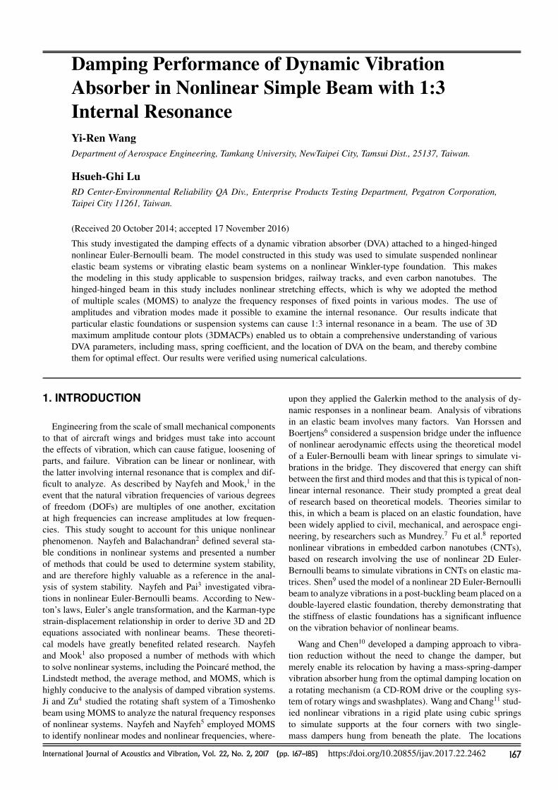
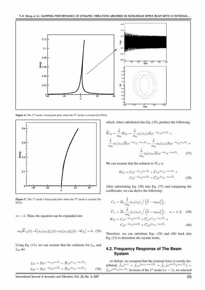
the nonlinear system without a DVA, we plotted the fixed pointplots to search for 1:3 internal resonance. The left part of Fig. 2displays the fixed points plots when the 1st mode (lower mode)is excited by a harmonic force. The horizontal axis measuresthe tuned frequency near the natural frequency in this mode,and the vertical axis measures the amplitude of vibration in thebeam. As can be seen in Fig. 2, multiple amplitudes may corre-spond to a single frequency. A system that resides within thisunstable region for long periods of time can undergo fatigueand damage. Figure 3 presents the fixed points plots of the 3rd
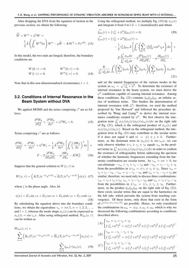
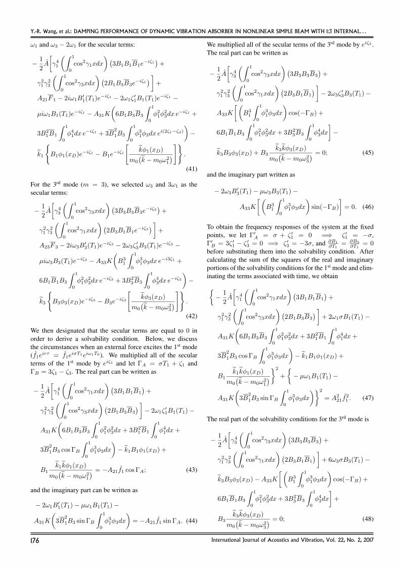
mode. When the 1st mode is being excited, the amplitudes ofthe 1st mode (Fig. 2) are greater than those of the 3rd mode(Fig. 3), which is normal. Fixed point plots of the 3rd modeunder excitation are presented in the left part of Fig. 4, andthe concurrent fixed point plots of the 1st mode are presentedin Fig. 5. A comparison of the two revealed that although it
was the 3rd mode that was being excited, the amplitudes in the1st mode were greater than those of the 3rd mode, due to theunique internal resonance associated with nonlinear systems.This proves that 1:3 internal resonance occurs in the 1st and 3rd
modes of the system.
3.5. Numerical VerificationTo ensure the internal resonance in the system, we employed
numerical calculations to verify the results in the fixed pointplots without the DVA (i.e., the solutions of Eqs. (26) to (28)).Since Eqs. (26) to (28) are the solvability conditions fromEq. (21), we substituted the vibration mode obtained usingEq. (21) into Eq. (13) and employed the orthogonal propertiesfor its integration, the result of which was then used to excitethe 1st mode, thus producing
∗∗ξ 1 + γ4
1ξ1 + µ∗ξ1 + ω2ξ1 +
k∫ 1
0φ2
1dxΓ1 +
1
2γ2
1ξ1
∫ 1
0
(γ2
1ξ21 cos2γ1x+ γ2
3ξ23 cos2γ3x
)dx = F
∫ 1
0φ1dx∫ 1
0φ2
1dx;
(29)
where
Γ1 =
∫ 1
0
(ξ31φ
31 + 3ξ2
1φ21ξ3φ3 + 3ξ1φ1ξ
23φ
23 + ξ3
3φ33
)φ1dx.
(30)When it was used to excite the 3rd mode, the outcome was
∗∗ξ 3 + γ4
3ξ3 + µ∗ξ3 + ω2ξ3 +
k∫ 1
0φ2
3dxΓ3 +
1
2γ2
3ξ3
∫ 1
0
(γ2
1ξ21 cos2γ1x+ γ2
3ξ23 cos2γ3x
)dx = F
∫ 1
0φ3dx∫ 1
0φ2
3dx;
(31)
where
Γ3 =
∫ 1
0
(ξ31φ
31 + 3ξ2
1φ21ξ3φ3 + 3ξ1φ1ξ
23φ
23 + ξ3
3φ33
)φ3dx.
(32)For the integration coefficients, please refer to Appendix 2.We used the Runge-Kutta (RK4) method to solve the dynamicequations (Eqs. (29) and (31)) and then drew time responsegraphs and Poincare maps. The right side of Fig. 2 presentsthe fixed point plot and the numerical verification graph of the1st mode; the upper graph displays the time responses, and thelower graph is the Poincare map. The horizontal axis of a fixedpoints plot represents the tuned frequency near the beam’s nat-ural frequency. Since the external forcing function was de-fined as fmeirτ = fme
i(ωm+εσ)T0 = fm(eiεσT0eiωmT0
)=
fmeiσT1eiωmT0 , we can see that when σ = 0, the dimension-
less forcing frequency r equals the beam’s mth natural fre-quency ωm. Physically, the fixed point plot displays the nonlin-ear steady-state (fixed point) frequency response near the sys-tem’s natural frequencies. The upper graph of Fig. 2 displaysthe time response graph obtained when σ = 4. The conver-gence value in this figure is the same as that of the fixed pointplot in the left side in Fig. 2 when σ = 4. The Poincare mapalso displays unstable in this case (chaos). The right side of
International Journal of Acoustics and Vibration, Vol. 22, No. 2, 2017 173
Y.-R. Wang, et al.: DAMPING PERFORMANCE OF DYNAMIC VIBRATION ABSORBER IN NONLINEAR SIMPLE BEAM WITH 1:3 INTERNAL. . .
Figure 2. The 1st mode’s fixed point plots when the 1st mode is excited (No DVA).
Figure 3. The 3rd mode’s fixed point plots when the 1st mode is excited (NoDVA).
Fig. 4 presents the fixed point plot and the numerical verifica-tion graph of the 3rd mode; again, the upper graph displays thetime responses, and the lower graph is the Poincare map forσ = 4. The convergence value of time response is the sameas in the left side in Fig. 4 when σ = 4. The Poincare mapalso displays unstable in this case (chaos). Both Figs. 2 and4 show that the internal resonance predicted in the fixed pointplots with no DVA is reasonable.
4. VIBRATION REDUCTION ANALYSIS OFDVA
This section expands on the results in Sections 2 and 3 byanalyzing the damping effects of a DVA on a suspended beamor a beam supported on an elastic foundation. We examined
the effects of the DVA fixed at various locations according tothe frequency responses of the overall system. The results arepresented in Section 5.
4.1. Analysis of DVA EquationWe assumed that the DVA motions constitute a single-point
force (xD denotes the location of the DVA). To enhance the in-fluence of the DVA and simplify the setup, we did not considerthe damping term of the DVA. Thus, the motion of equationfor ε1 can be written as
ε1 :∂2W1
∂T 20
+∂4W1
∂X4+ ω2W 1 =
∂2W0
∂X2
(1
2
∫ 1
0
(∂W0
∂X
)2
dx
)+ F − 2
∂2W0
∂T0∂T1−
µ∂W0
∂T0− kW 3
0 − k(W0(x, t)−WD
)δ(x−xD). (33)
The DVA equation is as follows:
m0
∗∗WD(t)− k
[ ∞∑m=1
Wm(x, t)−WD
]= 0. (34)
In Section 3, we established that 1:3 internal resonance occursin the main body between the modes of m = 1 and m = 3when ω = 3π2. Thus, we only discussed the 1st and the 3rd
modes (m = 1 and m = 3) of the system. It is noted thatthe spring force of the DVA is decided by the relative motionof the DVA (WD) and the beam (Wm). It can be expressedas k (Wm −WD). By using the Newton’s 2nd law, this forcecan be added on the beam shown in Eq. (33). As the DVA isconsidered an external force, we first solved the displacementof the DVA and then substituted it into the equation of motionfor the main body in Eq. (33). With Eq. (34), let m = 1 and
174 International Journal of Acoustics and Vibration, Vol. 22, No. 2, 2017
Y.-R. Wang, et al.: DAMPING PERFORMANCE OF DYNAMIC VIBRATION ABSORBER IN NONLINEAR SIMPLE BEAM WITH 1:3 INTERNAL. . .
Figure 4. The 3rd mode’s fixed point plots when the 3rd mode is excited (No DVA).
Figure 5. The 1st mode’s fixed point plots when the 3rd mode is excited (NoDVA).
m = 3. Then, the equation can be expanded into
m0
∗∗WD(t)−k
[φ1(xD)ξ1(t)+φ3(xD)ξ3(t)−WD
]= 0. (35)
Using Eq. (11), we can assume that the solutions for ξ10 andξ30 are
ξ10 = B1e−iζ1eiω1T0 +B1e
iζ1e−iω1T0 ;
ξ30 = B3e−iζ3eiω3T0 +B3e
iζ3e−iω3T0 ; (36)
which, when substituted into Eq. (35), produce the following:
∗∗WD +
k
m0WD =
k
m0φ1(xD)B1e
−iζ1eiω1T0 +
k
m0φ1(xD)B1e
−iζ1e−iω1T0 +k
m0φ3(xD)B3e
−iζ3eiω3T0 +
k
m0φ3(xD)B3e
−iζ3e−iω3T0 . (37)
We can assume that the solution to WD is
WD = C1e−iζ1eiω1T0 + C1e
iζ1e−iω1T0 +
C3e−iζ3eiω3T0 + C3e
iζ3e−iω3T0 . (38)
After substituting Eq. (38) into Eq. (37) and comparing thecoefficients, we can derive the following:
Cn = Bnk
m0φn(xD)
/(k −m0ω
2n
);
Cn = Bnk
m0φn(xD)
/(k −m0ω
2n
); n = 1, 3; (39)
WD = C1e−iζ1eiω1T0 + C1e
iζ1e−iω1T0 +
C3e−iζ3eiω3T0 + C3e
iζ3e−iω3T0 . (40)
Therefore, we can substitute Eqs. (39) and (40) back intoEq. (33) to determine the secular terms.
4.2. Frequency Response of The BeamSystem
As before, we assumed that the external force is evenly dis-tributed: fmeirτ = fme
i(ωm+εσ)T0 = fm(eiεσT0eiωmT0
)=
fmeiσT1eiωmT0 . In terms of the 1st mode (m = 1), we selected
International Journal of Acoustics and Vibration, Vol. 22, No. 2, 2017 175
Y.-R. Wang, et al.: DAMPING PERFORMANCE OF DYNAMIC VIBRATION ABSORBER IN NONLINEAR SIMPLE BEAM WITH 1:3 INTERNAL. . .
ω1 and ω3 − 2ω1 for the secular terms:
− 1
2A
[γ4
1
(∫ 1
0
cos2γ1xdx
)(3B1B1B1e
−iζ1)
+
γ21γ
23
(∫ 1
0
cos2γ3xdx
)(2B1B3B3e
−iζ1) ]
+
A21F 1 − 2iω1B′1(T1)e−iζ1 − 2ω1ζ
′1B1(T1)e−iζ1 −
µiω1B1(T1)e−iζ1 −A31K
(6B1B3B3
∫ 1
0
φ21φ
23dx e
−iζ1 +
3B21B1
∫ 1
0
φ41dx e
−iζ1 + 3B2
1B3
∫ 1
0
φ31φ3dx e
i(2ζ1−ζ3)
)−
k1
B1φ1(xD)e−iζ1 −B1e
−iζ1
[kφ1(xD)
m0
(k −m0ω2
1
)] .(41)
For the 3rd mode (m = 3), we selected ω3 and 3ω1 as thesecular terms:
− 1
2A
[γ4
3
(∫ 1
0
cos2γ3xdx
)(3B3B3B3e
−iζ3)
+
γ21γ
23
(∫ 1
0
cos2γ1xdx
)(2B3B1B1e
−iζ3) ]
+
A23F 3 − 2iω3B′3(T1)e−iζ3 − 2ω3ζ
′3B3(T1)e−iζ3 −
µiω3B3(T1)e−iζ3 −A33K
(B3
1
∫ 1
0
φ31φ3dx e
−i3ζ1 +
6B1B1B3
∫ 1
0
φ21φ
23dx e
−iζ3 + 3B23B3
∫ 1
0
φ43dx e
−iζ3)−
k3
B3φ3(xD)e−iζ3 −B3e
−iζ3
[kφ3(xD)
m0
(k −m0ω2
3
)] .(42)
We then designated that the secular terms are equal to 0 inorder to derive a solvability condition. Below, we discussthe circumstances when an external force excites the 1st mode(f1e
irτ = f1eiσT1eiω1T0 ). We multiplied all of the secular
terms of the 1st mode by eiζ1 and let ΓA = σT1 + ζ1 andΓB = 3ζ1 − ζ3. The real part can be written as
− 1
2A
[γ4
1
(∫ 1
0
cos2γ1xdx
)(3B1B1B1
)+
γ21γ
23
(∫ 1
0
cos2γ3xdx
)(2B1B3B3
) ]− 2ω1ζ
′1B1(T1)−
A31K
(6B1B3B3
∫ 1
0
φ21φ
23dx+ 3B2
1B1
∫ 1
0
φ41dx+
3B2
1B3 cos ΓB
∫ 1
0
φ31φ3dx
)− k1B1φ1(xD) +
B1k1kφ1(xD)
m0
(k −m0ω2
1
) = −A21f1 cos ΓA; (43)
and the imaginary part can be written as
− 2ω1B′1(T1)− µω1B1(T1)−
A31K
(3B
2
1B3 sin ΓB
∫ 1
0
φ31φ3dx
)= −A21f1 sin ΓA. (44)
We multiplied all of the secular terms of the 3rd mode by eiζ3 .The real part can be written as
− 1
2A
[γ4
3
(∫ 1
0
cos2γ3xdx
)(3B3B3B3
)+
γ21γ
23
(∫ 1
0
cos2γ1xdx
)(2B3B1B1
) ]− 2ω3ζ
′3B3(T1)−
A33K
[(B3
1
∫ 1
0
φ31φ3dx
)cos(−ΓB) +
6B1B1B3
∫ 1
0
φ21φ
23dx+ 3B2
3B3
∫ 1
0
φ43dx
]−
k3B3φ3(xD) +B3k3kφ3(xD)
m0
(k −m0ω2
3
) = 0; (45)
and the imaginary part written as
− 2ω3B′3(T1)− µω3B3(T1)−
A33K
[(B3
1
∫ 1
0
φ31φ3dx
)sin(−ΓB)
]= 0. (46)
To obtain the frequency responses of the system at the fixedpoints, we let Γ′A = σ + ζ ′1 = 0 =⇒ ζ ′1 = −σ,Γ′B = 3ζ ′1 − ζ ′3 = 0 =⇒ ζ ′3 = −3σ, and ∂B1
∂T1= ∂B3
∂T1= 0
before substituting them into the solvability condition. Aftercalculating the sum of the squares of the real and imaginaryportions of the solvability conditions for the 1st mode and elim-inating the terms associated with time, we obtain− 1
2A
[γ4
1
(∫ 1
0
cos2γ1xdx
)(3B1B1B1
)+
γ21γ
23
(∫ 1
0
cos2γ3xdx
)(2B1B3B3
) ]+ 2ω1σB1(T1)−
A31K
(6B1B3B3
∫ 1
0
φ21φ
23dx+ 3B2
1B1
∫ 1
0
φ41dx+
3B2
1B3 cos ΓB
∫ 1
0
φ31φ3dx
)− k1B1φ1(xD) +
B1k1kφ1(xD)
m0
(k −m0ω2
1
)2
+
− µω1B1(T1)−
A31K
(3B
2
1B3 sin ΓB
∫ 1
0
φ31φ3dx
)2
= A221f
21 . (47)
The real part of the solvability conditions for the 3rd mode is
− 1
2A
[γ4
3
(∫ 1
0
cos2γ3xdx
)(3B3B3B3
)+
γ21γ
23
(∫ 1
0
cos2γ1xdx
)(2B3B1B1
) ]+ 6ω3σB3(T1)−
k3B3φ3(xD)−A33K
[(B3
1
∫ 1
0
φ31φ3dx
)cos(−ΓB) +
6B1B1B3
∫ 1
0
φ21φ
23dx+ 3B2
3B3
∫ 1
0
φ43dx
]+
B3k3kφ3(xD)
m0
(k −m0ω2
3
) = 0; (48)
176 International Journal of Acoustics and Vibration, Vol. 22, No. 2, 2017
Y.-R. Wang, et al.: DAMPING PERFORMANCE OF DYNAMIC VIBRATION ABSORBER IN NONLINEAR SIMPLE BEAM WITH 1:3 INTERNAL. . .
(a) (b)
(c) (d)
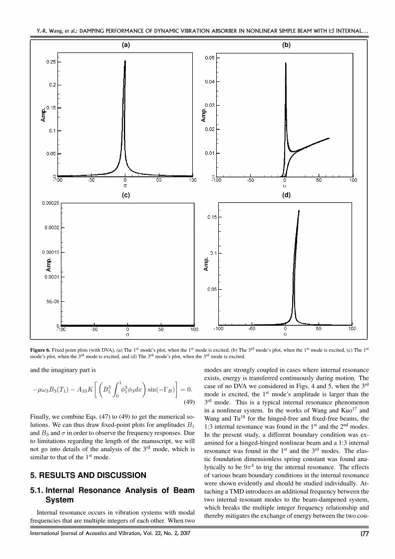
Figure 6. Fixed point plots (with DVA), (a) The 1st mode’s plot, when the 1st mode is excited, (b) The 3rd mode’s plot, when the 1st mode is excited, (c) The 1st
mode’s plot, when the 3rd mode is excited, and (d) The 3rd mode’s plot, when the 3rd mode is excited.
and the imaginary part is
−µω3B3(T1)−A33K
[(B3
1
∫ 1
0
φ31φ3dx
)sin(−ΓB)
]= 0.
(49)
Finally, we combine Eqs. (47) to (49) to get the numerical so-lutions. We can thus draw fixed-point plots for amplitudes B1
andB3 and σ in order to observe the frequency responses. Dueto limitations regarding the length of the manuscript, we willnot go into details of the analysis of the 3rd mode, which issimilar to that of the 1st mode.
5. RESULTS AND DISCUSSION
5.1. Internal Resonance Analysis of BeamSystem
Internal resonance occurs in vibration systems with modalfrequencies that are multiple integers of each other. When two
modes are strongly coupled in cases where internal resonanceexists, energy is transferred continuously during motion. Thecase of no DVA we considered in Figs. 4 and 5, when the 3rd
mode is excited, the 1st mode’s amplitude is larger than the3rd mode. This is a typical internal resonance phenomenonin a nonlinear system. In the works of Wang and Kuo17 andWang and Tu18 for the hinged-free and fixed-free beams, the1:3 internal resonance was found in the 1st and the 2nd modes.In the present study, a different boundary condition was ex-amined for a hinged-hinged nonlinear beam and a 1:3 internalresonance was found in the 1st and the 3rd modes. The elas-tic foundation dimensionless spring constant was found ana-lytically to be 9π4 to trig the internal resonance. The effectsof various beam boundary conditions in the internal resonancewere shown evidently and should be studied individually. At-taching a TMD introduces an additional frequency between thetwo internal resonant modes to the beam-dampened system,which breaks the multiple integer frequency relationship andthereby mitigates the exchange of energy between the two cou-
International Journal of Acoustics and Vibration, Vol. 22, No. 2, 2017 177

Y.-R. Wang, et al.: DAMPING PERFORMANCE OF DYNAMIC VIBRATION ABSORBER IN NONLINEAR SIMPLE BEAM WITH 1:3 INTERNAL. . .
Table 1. Normalized maximum amplitude of the 1st mode.
m0 k XD = 0.1 XD = 0.125 XD = 0.25 XD = 0.5
0.02 0.1 0.693029 0.652387 0.516591 0.4246620.02 0.2 0.698114 0.652374 0.51657 0.4268350.02 0.3 0.698111 0.65237 0.516564 0.4246310.02 0.4 0.695346 0.652365 0.516559 0.4246260.02 0.6 0.698107 0.652366 0.516557 0.4246240.02 0.7 0.695345 0.652364 0.516557 0.4246230.05 0.1 0.693113 0.652348 0.519716 0.4247110.05 0.2 0.692806 0.651563 0.516551 0.424560.05 0.3 0.695348 0.65175 0.51651 0.4248260.05 0.4 0.69299 0.651725 0.515925 0.4247940.05 0.6 0.692987 0.651722 0.515917 0.4247790.05 0.7 0.692984 0.651718 0.516463 0.4247720.07 0.1 0.828863 0.779646 0.620958 0.5092310.07 0.2 0.693079 0.653774 0.515912 0.4247770.07 0.3 0.69303 0.65152 0.519795 0.4246810.07 0.4 0.692987 0.652433 0.515934 0.4268120.07 0.6 0.692982 0.652428 0.515919 0.4245870.07 0.7 0.695312 0.652421 0.515907 0.426770.1 0.1 0.830796 0.780316 0.616474 0.5063210.1 0.2 0.693703 0.65157 0.516605 0.4245680.1 0.3 0.693088 0.652413 0.516048 0.4246790.1 0.4 0.692999 0.65231 0.515911 0.4245430.1 0.6 0.692989 0.651602 0.515879 0.4244840.1 0.7 0.695312 0.651801 0.51662 0.4244570.12 0.1 0.828966 0.779547 0.618058 0.5065930.12 0.2 0.693809 0.652407 0.516627 0.4261640.12 0.3 0.69366 0.65175 0.515989 0.4246140.12 0.4 0.693019 0.651601 0.516551 0.424730.12 0.6 0.693004 0.651583 0.516505 0.4246440.12 0.7 0.698082 0.655397 0.51609 0.4261710.15 0.1 0.829058 0.780938 0.617327 0.5066050.15 0.2 0.693002 0.651557 0.51656 0.4245860.15 0.3 0.693782 0.651755 0.516527 0.4247350.15 0.4 0.693064 0.652478 0.51659 0.4247340.15 0.6 0.698139 0.65245 0.516517 0.4245990.15 0.7 0.69301 0.652413 0.516082 0.424536
pled modes, thus resulting in a reduction in internal resonance.We employed numerical analysis to solve Eqs. (47) through(49), thereby obtaining the fixed points plots of the system.Figure 6 (the fixed point plots including the DVA) shows thatwhen the 3rd mode is excited, the amplitudes of the 1st mode(Fig. 6c) do not exceed those of the 3rd mode (Fig. 6d). Clearly,internal resonance does not occur. By comparing Fig. 6 withFigs. 2 through 5, we can see that the inclusion of the DVAin the system prevents 1:3 internal resonance in the 1st and3rd modes. It is possible that the damping effects of the DVAare directly associated with the vibrations of the main beam.In Eq. (7), the term k[W (x, τ) −WD]δ[x − lD] couples withW (x, t), which then merges with terms W iv and w2 to influ-ence (positively or negatively) the previous integer ratio of thefrequencies, 1:3. As a result, 1:3 internal resonance does notoccur.
5.2. Analyzing The Effectiveness of DVADamping
Using MOMS, eigen analysis, and fixed point plots, we es-tablished that 1:3 internal resonance occurs in the 1st and 3rd
modes of a main body without a DVA. A comprehensive viewof the two modes show that regardless of whether the 1st or 3rd
mode is excited, the maximum amplitudes in the 1st and 3rd
modes are 0.598675 and 0.11921, respectively. We thus usedthese amplitudes as the basis for comparisons used to evaluatethe effectiveness of damping. In previous sections, we already
Table 2. Normalized maximum amplitude of the 3rd mode.
m0 k XD = 0.1 XD = 0.125 XD = 0.25 XD = 0.5
0.02 0.1 1.464852 1.728147 1.478419 1.7781850.02 0.2 1.07284 1.229764 1.638418 2.2741890.02 0.3 1.467375 1.726061 1.78791 2.1197840.02 0.4 1.467676 1.725644 2.104751 2.4814690.02 0.6 1.027626 1.228464 2.177923 2.5557670.02 0.7 1.417364 1.725503 1.597176 2.6855150.05 0.1 1.40992 1.770635 1.378139 1.6686630.05 0.2 1.026374 1.26479 1.392248 1.7729260.05 0.3 1.439894 1.747833 1.431815 1.727150.05 0.4 1.442745 1.74515 1.531946 1.8392840.05 0.6 1.018009 1.255225 1.556726 1.8640860.05 0.7 1.444224 1.744312 1.597176 2.0484760.07 0.1 1.055878 1.606127 2.179459 2.2784830.07 0.2 1.404675 1.296659 1.34855 1.6631020.07 0.3 1.416868 1.765247 1.357211 1.6460240.07 0.4 1.423382 1.759675 1.39794 1.6913710.07 0.6 0.966909 1.274386 1.409035 1.7023370.07 0.7 1.426958 1.757671 1.427694 1.7225620.1 0.1 0.004963 0.001511 0.00313 0.0013220.1 0.2 0.836822 1.365858 1.33042 1.5796340.1 0.3 1.373034 1.797928 1.304739 1.5889340.1 0.4 1.389869 1.783871 1.290711 1.5736210.1 0.6 0.927665 1.305452 1.28927 1.5721920.1 0.7 1.398384 1.779369 1.287593 1.5702950.12 0.1 1.458676 1.184319 1.436823 1.594920.12 0.2 0.799082 1.437811 1.339805 1.5486110.12 0.3 1.334119 1.824971 1.288543 1.5713230.12 0.4 1.363762 1.801805 1.295016 1.5270460.12 0.6 0.891536 1.327901 1.240718 1.5200590.12 0.7 1.377175 1.794745 1.229752 1.5081420.15 0.1 1.33262 1.341661 1.690585 1.8226540.15 0.2 1.003977 1.6405 1.401304 1.5216380.15 0.3 1.25403 1.879512 1.28088 1.5631330.15 0.4 1.316419 1.832141 1.20584 1.4811790.15 0.6 0.887034 1.364301 1.192195 1.4677810.15 0.7 1.341841 1.819752 1.17053 1.444635
established that adding a DVA with another DOF to the modeldamages the natural vibration frequency ratios of the variousmodes, due to the fact that the additional DOF couples with theequation of motion of the beam. As a result, internal resonancedoes not occur. In this section, we examine various parametersof the DVA, including mass ratio, spring constant ratio, and lo-cation, to identify the combination with the optimal dampingeffects. Using the solvability condition and fixed point plots inSection 4, we derived the maximum amplitude in the 1st modewhen excited, and then normalized the results using the maxi-mum amplitude obtained in cases without a DVA (0.598675).To achieve this, we considered the mass ratio (the mass of theDVA / the mass of the beam) and the spring constant ratio (thespring constant of the DVA / the spring constant of the elas-tic foundation). The normalized maximum amplitudes of the1st mode are shown in Table 1. Similarly, we normalized themaximum amplitude in the 3rd mode when excited by usingthe maximum amplitude in cases without a DVA (0.11921).Again, the results are shown in Table 2. To avoid the diffi-culties associated with an excessive number of DVA parame-ters in the tables, we used 3D maximum amplitude projections(3DMACPs) to reveal the influence of parameters on dampingperformance. The results of 3DMACPs will be shown in nexttwo paragraphs.
This study uses the 3D projections to project the maximumamplitudes of various parameter combinations onto the mass-spring constant plane and combine various locations into a 3Dmaximum amplitude contour plot (3DMACP). Physically, the
178 International Journal of Acoustics and Vibration, Vol. 22, No. 2, 2017
Y.-R. Wang, et al.: DAMPING PERFORMANCE OF DYNAMIC VIBRATION ABSORBER IN NONLINEAR SIMPLE BEAM WITH 1:3 INTERNAL. . .
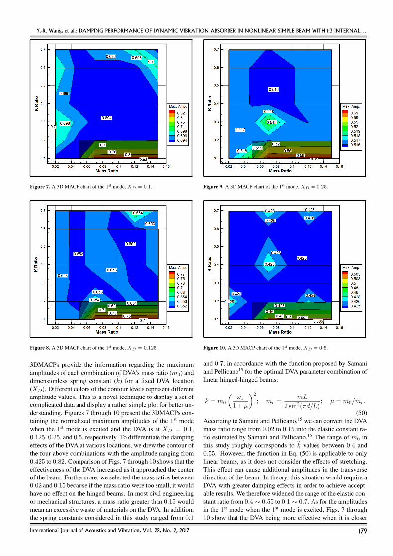
Figure 7. A 3D MACP chart of the 1st mode, XD = 0.1.
Figure 8. A 3D MACP chart of the 1st mode, XD = 0.125.
3DMACPs provide the information regarding the maximumamplitudes of each combination of DVA’s mass ratio (m0) anddimensionless spring constant (k) for a fixed DVA location(XD). Different colors of the contour levels represent differentamplitude values. This is a novel technique to display a set ofcomplicated data and display a rather simple plot for better un-derstanding. Figures 7 through 10 present the 3DMACPs con-taining the normalized maximum amplitudes of the 1st modewhen the 1st mode is excited and the DVA is at XD = 0.1,0.125, 0.25, and 0.5, respectively. To differentiate the dampingeffects of the DVA at various locations, we drew the contour ofthe four above combinations with the amplitude ranging from0.425 to 0.82. Comparison of Figs. 7 through 10 shows that theeffectiveness of the DVA increased as it approached the centerof the beam. Furthermore, we selected the mass ratios between0.02 and 0.15 because if the mass ratio were too small, it wouldhave no effect on the hinged beams. In most civil engineeringor mechanical structures, a mass ratio greater than 0.15 wouldmean an excessive waste of materials on the DVA. In addition,the spring constants considered in this study ranged from 0.1
Figure 9. A 3D MACP chart of the 1st mode, XD = 0.25.
Figure 10. A 3D MACP chart of the 1st mode, XD = 0.5.
and 0.7, in accordance with the function proposed by Samaniand Pellicano15 for the optimal DVA parameter combination oflinear hinged-hinged beams:
k = m0
(ω1
1 + µ
)2
; me =mL
2 sin2(πd/L); µ = m0/me.
(50)According to Samani and Pellicano,15 we can convert the DVAmass ratio range from 0.02 to 0.15 into the elastic constant ra-tio estimated by Samani and Pellicano.15 The range of m0 inthis study roughly corresponds to k values between 0.4 and0.55. However, the function in Eq. (50) is applicable to onlylinear beams, as it does not consider the effects of stretching.This effect can cause additional amplitudes in the transversedirection of the beam. In theory, this situation would require aDVA with greater damping effects in order to achieve accept-able results. We therefore widened the range of the elastic con-stant ratio from 0.4 ∼ 0.55 to 0.1 ∼ 0.7. As for the amplitudesin the 1st mode when the 1st mode is excited, Figs. 7 through10 show that the DVA being more effective when it is closer
International Journal of Acoustics and Vibration, Vol. 22, No. 2, 2017 179
Y.-R. Wang, et al.: DAMPING PERFORMANCE OF DYNAMIC VIBRATION ABSORBER IN NONLINEAR SIMPLE BEAM WITH 1:3 INTERNAL. . .
Figure 11. A 3D MACP chart of the 3rd mode, XD = 0.1.
Figure 12. A 3D MACP chart of the 3rd mode, XD = 0.125.
to the center of the beam a higher mass ratios do not actuallyhave significant damping effects. On the contrary, excessivelyhigh mass ratios can magnify the amplitudes in transverse vi-brations in the beam (because a DVA is included). We alsofound that such DVA designs are more effective in dampingthe 1st mode. Similarly, damping effects are better when theDVA is closer to the center of the beam. Nonetheless, com-binations with m0 between 0.05 and 0.15 and k less than 0.2must still be avoided.
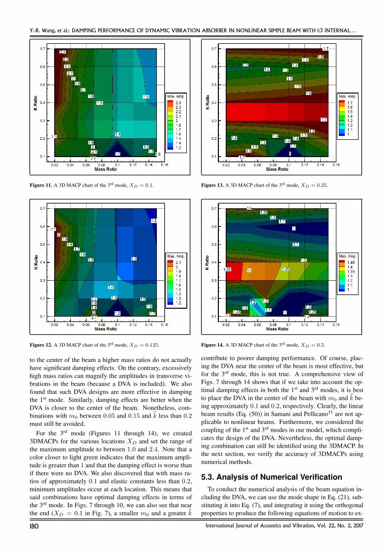
For the 3rd mode (Figures 11 through 14), we created3DMACPs for the various locations XD and set the range ofthe maximum amplitude to between 1.0 and 2.4. Note that acolor closer to light green indicates that the maximum ampli-tude is greater than 1 and that the damping effect is worse thanif there were no DVA. We also discovered that with mass ra-tios of approximately 0.1 and elastic constants less than 0.2,minimum amplitudes occur at each location. This means thatsaid combinations have optimal damping effects in terms ofthe 3rd mode. In Figs. 7 through 10, we can also see that nearthe end (XD = 0.1 in Fig. 7), a smaller m0 and a greater k
Figure 13. A 3D MACP chart of the 3rd mode, XD = 0.25.
Figure 14. A 3D MACP chart of the 3rd mode, XD = 0.5.
contribute to poorer damping performance. Of course, plac-ing the DVA near the center of the beam is most effective, butfor the 3rd mode, this is not true. A comprehensive view ofFigs. 7 through 14 shows that if we take into account the op-timal damping effects in both the 1st and 3rd modes, it is bestto place the DVA in the center of the beam with m0 and k be-ing approximately 0.1 and 0.2, respectively. Clearly, the linearbeam results (Eq. (50)) in Samani and Pellicano15 are not ap-plicable to nonlinear beams. Furthermore, we considered thecoupling of the 1st and 3rd modes in our model, which compli-cates the design of the DVA. Nevertheless, the optimal damp-ing combination can still be identified using the 3DMACP. Inthe next section, we verify the accuracy of 3DMACPs usingnumerical methods.
5.3. Analysis of Numerical VerificationTo conduct the numerical analysis of the beam equation in-
cluding the DVA, we can use the mode shape in Eq. (21), sub-stituting it into Eq. (7), and integrating it using the orthogonalproperties to produce the following equations of motion to ex-
180 International Journal of Acoustics and Vibration, Vol. 22, No. 2, 2017

Y.-R. Wang, et al.: DAMPING PERFORMANCE OF DYNAMIC VIBRATION ABSORBER IN NONLINEAR SIMPLE BEAM WITH 1:3 INTERNAL. . .
(a)
(b)
Figure 15. Numerical verification, (a) m0 = 0.15, k = 0.1, XD = 0.1, (b) m0 = 0.02, k = 0.7, XD = 0.1.
cite the 1st mode:
∗∗ξ 1 + γ4
1ξ1 + µ∗ξ1 + ω2ξ1 +
k∫ 1
0φ2
1dxΓ1 +
1
2γ2
1ξ1
∫ 1
0
(γ2
1ξ21 cos2γ1x+ γ2
3ξ23 cos2γ3x
)dx
fs [ξ1φ1(XD) + ξ3φ3(XD)−WDφ(XD)] = F
∫ 1
0φ1dx∫ 1
0φ2
1dx;
(51)
where
Γ1 =
∫ 1
0
(ξ31φ
31 + 3ξ2
1φ21ξ3φ3 + 3ξ1φ1ξ
23φ
23 + ξ3
3φ33
)φ1dx;
(52)
and to excite the 3rd mode:
∗∗ξ 3 + γ4
3ξ3 + µ∗ξ3 + ω2ξ3 +
k∫ 1
0φ2
3dxΓ3 +
1
2γ2
3ξ3
∫ 1
0
(γ2
1ξ21 cos2γ1x+ γ2
3ξ23 cos2γ3x
)dx
fs [ξ1φ1(XD) + ξ3φ3(XD)−WDφ(XD)] = F
∫ 1
0φ3dx∫ 1
0φ2
3dx;
(53)
where
Γ3 =
∫ 1
0
(ξ31φ
31 + 3ξ2
1φ21ξ3φ3 + 3ξ1φ1ξ
23φ
23 + ξ3
3φ33
)φ3dx.
(54)Please refer to Appendix 2 for the relevant integration coeffi-cients. We employed the RK4 approach to calculate displace-ments in the nonlinear beam with various parameter and loca-tion combinations when excited by a given external frequency.
International Journal of Acoustics and Vibration, Vol. 22, No. 2, 2017 181

Y.-R. Wang, et al.: DAMPING PERFORMANCE OF DYNAMIC VIBRATION ABSORBER IN NONLINEAR SIMPLE BEAM WITH 1:3 INTERNAL. . .
(a)
(b)
Figure 16. Numerical verification, (a) m0 = 0.15, k = 0.1, XD = 0.5, (b) m0 = 0.02, k = 0.7, XD = 0.5.
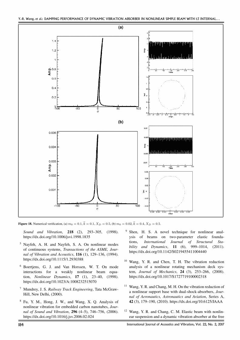
To verify the results from 3DMACPs (Figs. 7 to 14), we per-formed the numerical analysis and cross-referred the numeri-cal results, fixed points plots and Poincare maps (Figs. 15 to18). The left part of Fig. 15a displays the fixed point plot ofFig. 7 with m0 = 0.15, k = 0.1, and XD = 0.1 lain over thenumerical results of the maximum amplitudes. The right uppergraph of Fig. 15a displays the numerical result of time responseand the lower graph is the numerical result of Poincare map.Figure 15b shows the same with m0 = 0.02, k = 0.7, andXD = 0.1. The left part of Fig. 16a exhibits the fixed point plotof Fig. 10 with m0 = 0.15, k = 0.1, and XD = 0.5 lain overthe numerical results of the maximum amplitudes. The rightupper graph of Fig. 16a displays the time response, and thelower graph is the Poincare map. Figure 16b shows the samewith m0 = 0.02, k = 0.7, and XD = 0.5. As before, Fig. 17adisplays the fixed point plot of Fig. 11 withm0 = 0.1, k = 0.1,and XD = 0.1 lain over the numerical results of the maximumamplitudes, and Fig. 17b shows the same with m0 = 0.02,k = 0.7, and XD = 0.1. Figure 18a displays the fixed point
plot of Fig. 14 with m0 = 0.1, k = 0.1, and XD = 0.5lain over the numerical results of the maximum amplitudes,and Fig. 18b shows the same with m0 = 0.02, k = 0.4, andXD = 0.5. Comparing the 3DMACPs with the fixed pointplots and numerical method (time response), for each speci-fied value of m0, k, and XD, the maximum value of the fixedpoint plots agrees with the 3DMACP and the numerical results.We can see that the results are consistent, thereby demonstrat-ing the accuracy of the model developed in this study and theconcept of 3DMACPs.
6. CONCLUSIONS
In this study, we considered a hinged-hinged nonlinear beamsupported or suspended by nonlinear springs to simulate a sys-tem that is suspended or placed on an elastic foundation. Wesubjected the main body to a harmonic force. Both ends ofthe nonlinear elastic beam are hinged; therefore, we had takeinto account the effects of stretching. We added a DVA to
182 International Journal of Acoustics and Vibration, Vol. 22, No. 2, 2017

Y.-R. Wang, et al.: DAMPING PERFORMANCE OF DYNAMIC VIBRATION ABSORBER IN NONLINEAR SIMPLE BEAM WITH 1:3 INTERNAL. . .
(a)
(b)
Figure 17. Numerical verification, (a) m0 = 0.1, k = 0.1, XD = 0.1, (b) m0 = 0.02, k = 0.7, XD = 0.1.
the beam system and investigated its effectiveness in dampingwhen place in various locations. Using some elastic constantcombinations, 1:3 internal resonance occurred in the 1st and3rd modes. Placing the DVA at suitable locations was shownto prevent this, such that the damping effects of the DVA aremore apparent in the 1st mode than in the 3rd mode. Dampingperformance was more significant when the DVA was closerto the center of the beam; however, 3DMACPs showed thatoptimal parameter combinations could also be found when theDVA was placed in other locations. For the 1st mode, smallerelastic constants and larger mass ratios are not recommended.As for the 3rd mode, damping performance is better when theDVA is near the center of the beam; however, the best resultsare obtained when the mass ratio is approximately 0.1 and theelastic constant is less than 0.2. For the best damping perfor-mance in both the 1st and 3rd modes, the ideal combinationincludes the DVA at the center of the beam with the mass ratioand elastic constant of approximately 0.1 and 0.2, respectively.
ACKNOWLEDGEMENTS
This research was supported by the Ministry of Scienceand Technology of Taiwan, Republic of China (grant number:MOST 103-2221-E-032-047).
REFERENCES1 Nayfeh, A. H. and Mook, D. T. Nonlinear Oscillations,
Wiley-Interscience, New York, (1979).
2 Nayfeh, A. H. and Balachandran, B. Applied Nonlinear Dy-namics, Wiley-Interscience, New York, 158–172, (1995).
3 Nayfeh, A. H. and Pai, P. F. Linear and Nonlinear Struc-tural Mechanics, New York, (2004).
4 Ji, Z. and Zu, J. W. Method of multiple scalesfor vibration analysis of rotor-shaft systems withnon-linear bearing pedestal model, Journal of
International Journal of Acoustics and Vibration, Vol. 22, No. 2, 2017 183
Y.-R. Wang, et al.: DAMPING PERFORMANCE OF DYNAMIC VIBRATION ABSORBER IN NONLINEAR SIMPLE BEAM WITH 1:3 INTERNAL. . .
(a)
(b)
Figure 18. Numerical verification, (a) m0 = 0.1, k = 0.1, XD = 0.5, (b) m0 = 0.02, k = 0.4, XD = 0.5.
Sound and Vibration, 218 (2), 293–305, (1998).https://dx.doi.org/10.1006/jsvi.1998.1835
5 Nayfeh, A. H. and Nayfeh, S. A. On nonlinear modesof continuous systems, Transactions of the ASME, Jour-nal of Vibration and Acoustics, 116 (1), 129–136, (1994).https://dx.doi.org/10.1115/1.2930388
6 Boertjens, G. J. and Van Horssen, W. T. On modeinteractions for a weakly nonlinear beam equa-tion, Nonlinear Dynamics, 17 (1), 23–40, (1998).https://dx.doi.org/10.1023/A:1008232515070
7 Mundrey, J. S. Railway Track Engineering, Tata McGraw-Hill, New Delhi, (2000).
8 Fu, Y. M., Hong, J. W., and Wang, X. Q. Analysis ofnonlinear vibration for embedded carbon nanotubes, Jour-nal of Sound and Vibration, 296 (4–5), 746–756, (2006).https://dx.doi.org/10.1016/j.jsv.2006.02.024
9 Shen, H. S. A novel technique for nonlinear anal-ysis of beams on two-parameter elastic founda-tions, International Journal of Structural Sta-bility and Dynamics, 11 (6), 999–1014, (2011).https://dx.doi.org/10.1142/S0219455411004440
10 Wang, Y. R. and Chen, T. H. The vibration reductionanalysis of a nonlinear rotating mechanism deck sys-tem, Journal of Mechanics, 24 (3), 253–266, (2008).https://dx.doi.org/10.1017/S1727719100002318
11 Wang, Y. R. and Chang, M. H. On the vibration reduction ofa nonlinear support base with dual-shock-absorbers, Jour-nal of Aeronautics, Astronautics and Aviation, Series A,42 (3), 179–190, (2010). https://dx.doi.org/10.6125/JAAA
12 Wang, Y. R. and Chang, C. M. Elastic beam with nonlin-ear suspension and a dynamic vibration absorber at the free
184 International Journal of Acoustics and Vibration, Vol. 22, No. 2, 2017
Y.-R. Wang, et al.: DAMPING PERFORMANCE OF DYNAMIC VIBRATION ABSORBER IN NONLINEAR SIMPLE BEAM WITH 1:3 INTERNAL. . .
end, Transaction of the Canadian Society for MechanicalEngineering (TCSME), 38 (1), 107–137, (2014).
13 Nambu, Y., Yamamoto, S., and Chiba, M. A smartdynamic vibration absorber for suppressing the vibra-tion of a string supported by flexible beams, SmartMaterials and Structures, 23 (2), 025032, (2014).https://dx.doi.org/10.1088/0964-1726/23/2/025032
14 Tso, M. H., Yuan, J., and Wong, W. O. Suppression of ran-dom vibration in flexible structures using a hybrid vibrationabsorber, Journal of Sound and Vibration, 331 (5), 974–986, (2012). https://dx.doi.org/10.1016/j.jsv.2011.10.017
15 Samani, F. S. and Pellicano, F. Vibration reductionof beams under successive traveling loads by meansof linear and nonlinear dynamic absorbers, Journal ofSound and Vibration, 331 (10), 2272–2290, (2012).https://dx.doi.org/10.1016/j.jsv.2012.01.002
16 Wang, Y. R. and Lin, H. S. Stability analysis andvibration reduction for a two-dimensional non-linear system, International Journal of StructuralStability and Dynamics, 13 (5), 1350031, (2013).https://dx.doi.org/10.1142/S0219455413500314
17 Wang, Y. R. and and Kuo, T. H. Effects of a dynamicvibration absorber on nonlinear hinged-free beam,ASCE Journal of Engineering Mechanics, 142 (4),(2016). https://dx.doi.org/10.1061/(ASCE)EM.1943-7889.0001039
18 Wang, Y. R. and Tu, S. C. Influence of tuned mass damperon fixed-free 3D nonlinear beam embedded in nonlinearelastic foundation, Meccanica, 51 (10), 2377–2416, (2016).https://dx.doi.org/10.1007/s11012-016-0372-8
19 Wang, Y. R. and Liang, T. W. Application of lumped-massvibration absorber on the vibration reduction of a non-linear beam-spring-mass system with internal resonances,Journal of Sound and Vibration, 350, 140–170, (2015).https://dx.doi.org/10.1016/j.jsv.2015.04.002
20 Ansari, R., Pourashraf, T., and Gholami, R. An exact so-lution for the nonlinear forced vibration of functionallygraded nanobeams in thermal environment based on sur-face elasticity theory, Thin-Walled Structures, 93, 169–176,(2015). https://dx.doi.org/10.1016/j.tws.2015.03.013
21 Sayed, M. and Kamel, M. 1 to 2 and 1 to 3 internal reso-nance active absorber for non-linear vibrating system, Ap-plied Mathematical Modelling, 36 (1), 310–332, (2012).https://dx.doi.org/10.1016/j.apm.2011.05.057
22 Ghayesh, M. H., Kazemirad, S., and Amabili, M.Coupled longitudinal-transverse dynamics of anaxially moving beam with an internal resonance,Mechanism and Machine Theory, 52, 18–34, (2012).https://dx.doi.org/10.1016/j.mechmachtheory.2012.01.008
23 Ghayesh, M. H. and Amabili, M. Nonlinear dynamicsof an axially moving Timoshenko beam with an internalresonance, Nonlinear Dynamics, 73 (1), 39–52, (2013).https://dx.doi.org/10.1007/s11071-013-0765-3
24 Ansari, R., Hasrati, E., Gholami, R., and, Sadeghi,F. Nonlinear analysis of forced vibration of non-local third-order shear deformable beam modelof magneto–electro–thermo elastic nanobeams,Composites: Part B, 83, 226–241, (2015).https://dx.doi.org/10.1016/j.compositesb.2015.08.038
25 Ansari, R., Mohammadi, V., Faghih Shojaei, M.,Gholami, R., and Sadeghi, F. Nonlinear forcedvibration analysis of functionally graded car-bon nanotube-reinforced composite Timoshenkobeams, Composite Structures, 113, 316–327, (2014).https://dx.doi.org/10.1016/j.compstruct.2014.03.015
26 Ansari, R., Faghih Shojaei, M., Mohammadi, V., Gholami,R., and Sahmani, S. On the forced vibration analysis ofTimoshenko nanobeams based on the surface stress elas-ticity theory, Composites: Part B, 60, 158–166, (2014).https://dx.doi.org/j.compositesb.2013.12.066
27 Ansari, R., Gholami, R., and Rouhi, H. Size-dependent nonlinear forced vibration analysisof magneto-electro-thermo-elastic Timoshenkonanobeams based upon the nonlocal elasticity the-ory, Composite Structures, 126, 216–226, (2015).https://dx.doi.org/10.1016/j.compstruct.2015.02.068
28 Ansari, R. and Gholami, R. Surface effect on thelarge amplitude periodic forced vibration of first-ordershear deformable rectangular nanoplates with variousedge supports, Acta Astronautica, 118, 72–89, (2016).https://dx.doi.org/10.1016/j.actaastro.2015.09.020
APPENDIX 1
W =W
l; τ =
t
l2
(EIAρA
)1/2
; ω =
(EIA
ρAl4
)1/2
;
x =x
l; l =
l
l= 1; µ =
mul2
(ρAEIA)1/2
;
A =EAr2
EIA— non-dimensional beam rigidity, and r is the
beam cross-section radius; Ω = Ωl2(ρA
EIA
)1/2
;
ω2 =kl
4
EIA; K =
βr2kl4
EIA; m0 =
m
ρAl;
k =fs
ω2ρAl; λ =
gsωρAl
.
APPENDIX 2
km =k∫ 1
0sin2γmxdx
; A2m =
∫ 1
0sin γmxdx∫ 1
0sin2γmxdx
;
A3m =1∫ 1
0sin2γmxdx
.
International Journal of Acoustics and Vibration, Vol. 22, No. 2, 2017 185