Embed Size (px)
Citation preview

Loughborough UniversityInstitutional Repository
Damping effects introducedby a nonlinear vibrationabsorber in automotivedrivelines at idle engine
speeds
This item was submitted to Loughborough University's Institutional Repositoryby the/an author.
Citation: SAVVA, K. ... et al., 2016. Damping effects introduced by a non-linear vibration absorber in automotive drivelines at idle engine speeds. SAETechnical Paper 2016-01-1765, 2016, doi:10.4271/2016-01-1765.
Additional Information:
• This conference paper was published in the Proceedings of the 9th Inter-national Styrian Noise, Vibration & Harshness Congress: The EuropeanAutomotive Noise Conference, Graz, Austria, 22-24 June, 7pp. [ c© SAEInternational]
Metadata Record: https://dspace.lboro.ac.uk/2134/21525
Version: Accepted for publication
Publisher: c© SAE International
Rights: This work is made available according to the conditions of the Cre-ative Commons Attribution-NonCommercial-NoDerivatives 4.0 International(CC BY-NC-ND 4.0) licence. Full details of this licence are available at:https://creativecommons.org/licenses/by-nc-nd/4.0/
Please cite the published version.
Page 1 of 7
16SNVH-0087
Damping effects introduced by a nonlinear vibration absorber in automotive drivelines at idle engine speeds
Author, co-author (Do NOT enter this information. It will be pulled from participant tab in MyTechZone)
Affiliation (Do NOT enter this information. It will be pulled from participant tab in MyTechZone)
Abstract
Legislation on vehicle emissions and the requirements for fuel efficiency are currently the key development driving factors in the automotive industry. Research activities to comply with these targets point to engine downsizing and new boosting technologies, which have adverse effects on the NVH performance, durability and component life. As a consequence of engine downsizing, substantial torsional oscillations are generated due to high combustion pressures. Meanwhile, to attenuate torsional vibrations, the manufacturers have implemented absorbers that are tuned to certain frequency ranges, including clutch dampers, Dual Mass Flywheel (DMF) and centrifugal pendulum dampers. These devices add mass/inertia to the system, potentially introducing negative effects on other vehicle attributes, such as weight, driving performance and gear shiftability.
This paper provides a study of torsional damping effects of nonlinear vibration absorbers on drivetrain NVH refinement by attenuating torsional oscillations at the idling engine speeds. The nonlinear absorber concept presented operates on the principle of Targeted Energy Transfer (TET), whereby the energy excess (vibration) from a donor (primary powertrain system) is transferred to a receiver (nonlinear absorber) in a nearly irreversible manner. Thereafter, the received energy can be absorbed, dissipated, or redistributed. This potentially allows the absorber to operate over a broadband frequency range, whilst being light and compact, which is ideal for automotive powertrains. In the present work, simulations are performed using an automotive drivetrain (subsystem) model with a nonlinear absorber. The damping content of the absorber is varied to study its effect on the attenuation of torsional oscillations.
Introduction
In recent decades, the continuous demand for comfortable and quiet vehicles has encouraged the development of methods to improve performance, efficiency, and comfort levels [1, 2]. Some major sources of vibration are the excitations produced by combustion and reciprocating inertial dynamics [3-5]. Therefore, minimizing the transmission of vibration and noise generated by the internal combustion engine is a major concern.
Various methods have been developed and implemented to reduce powertrain vibrations. The common approaches relate to powertrain mounts and powertrain torque transfer paths. Engine and powertrain mounts are used for vibration isolation within the engine operational speed range, thus requiring their stiffness and damping to be frequency and amplitude dependent [6]. Other techniques, such as
Torque Roll Axis (TRA) [7] have also been developed to decouple the engine vibration modes from the vehicle chassis.
Reducing vibrations along the Powertrain Driveline route in manual transmissions is accomplished by clutch disc damper springs together with in-line clutch actuation damper mechanisms [8, 9]. More refined systems include Dual Mass Flywheels (DMF) with configurations specifically designed to reduce the torsional impulses in the manual transmission [10], while in combination with CPA (Centrifugal Pendulum vibration Absorbers), a further improvement of vibration attenuation is obtained especially at creep speeds. However, vibration energy in modern downsized turbocharged engines exists in a broadband response, for which the above mentioned classical methods do not respond effectively. The performance of the linear tuned vibration absorber can degrade over time also due to aging of the system, temperature or as the result of part-to-part variations, requiring additional adjustment or tuning parameters [11].
A specific class of absorbers, termed as Nonlinear Energy Sink (NES), has been proposed to mitigate broadband powertrain torsional vibrations more effectively [12]. An NES comprises essential nonlinear stiffness, thus it does not possess a preferential resonance frequency, generating a variety of nonlinear resonant conditions. When coupled to a linear structure an NES can absorb the energy excess in an irreversible manner.
Targeted Energy Transfer (TET) is a phenomenon where the vibration energy is directed from a primary source to a strongly nonlinear attachment [13]. The NES can act as broadband passive and adaptive controller by absorbing energy from the primary structure irreversibly. This occurs via transient resonance captures, made possible by the stiffness essential nonlinearity of the NES [14]. Gendelman [15] has studied the transient dynamics of a two-Degree-of-Freedom system comprising a damped linear oscillator which was weakly coupled to an essentially nonlinear, damped attachment. Vakakis [16] investigated TET pumping from an impulsively loaded linear system to a NES by assuming the linear system to be a chain of elastically interconnected particles. The underlying theory, principles and modalities of energy pumping through NES were discussed in [17-21]. The external disturbances are eliminated through NES passively, since the latter can generate a large number of nonlinear resonant conditions, through which substantial energy transfer takes place between the two oscillators.
Various TET applications have been presented in the literature. Mitigating the seismic structural response [22, 23], where Al-Shudefait et al. [24] implemented two vibro-impact (VI) NES absorbers to alleviate the seismic vibrations in a nine story building.

Page 2 of 7
Viguie et al. [20] implemented a discrete torsional NES to stabilise a drill-string system. Nevertheless, TET has not yet found any noticeable applications in automotive industry. In this regard, Wang et al. [21] investigated the ability of an NES absorber to mitigate the large accelerations transmitted to a passenger compartment of a vehicle subjected to shock-type transient loading at the chassis. They applied a single VI absorber to the chassis and examined whether the resulting energy transfer mechanism is an effective way to reduce the peak value of the inertial force measured at the passenger compartment. The study demonstrated that properly designed VI absorber (NES) can significantly decrease the maximum inertial force produced by external impulsive excitations. Haris et al. [12] studied application of NES to drivetrains in order to reduce the gearbox input shaft torsional vibrations over a broadband frequency range. The NES design assumed engine transient speeds conditions.
The current study focuses on the engine idle conditions, analysing the effect of NES on the variations of the loss factor, η (ratio of energy dissipated by the NES’s damping over the energy stored within it). The performance evaluation of the system also considers the reduction of amplitude of the transmission input shaft angular velocity. The aim is to investigate how the damping introduced by NES affects its ability to attenuate engine-transmitted torsional oscillations (i.e. engine order vibration).
DRIVETRAIN MODEL
The model of the Front-Wheel-Drive (FWD) drivetrain is presented in Figure 1, comprising a solid Flywheel (JF), clutch damper (JC) and the transmission input shaft (JIN). The engine input torque is introduced into the system by prescribing the motion of the flywheel �̇�𝜃𝐹𝐹, as a function of the crankshaft’s mean angular velocity (�̇�𝜽𝒇𝒇𝒇𝒇) and its main harmonic with peak amplitude (𝜽𝜽𝒇𝒇𝒇𝒇) at frequency (ωf), where:
�̇�𝜽𝑭𝑭= �̇�𝜽𝒇𝒇𝒇𝒇 + �̇�𝜽𝒇𝒇𝒇𝒇 × 𝒔𝒔𝒔𝒔𝒔𝒔(𝝎𝝎𝒇𝒇 × 𝒕𝒕) (1)
where, �̇�𝜽𝒇𝒇𝒇𝒇 = 84 rad/s, �̇�𝜽𝒇𝒇𝒇𝒇 = 8.4 rad/s and 𝝎𝝎𝒇𝒇 =168 rad/s
Figure 1: The drivetrain model
The transmitted torque from the flywheel to the clutch is via the friction lining interface, represented by torsional linear stiffness 𝑘𝑘1 and damping coefficient 𝑐𝑐1. Subsequently, the clutch assembly actuates its torsional spring 𝑘𝑘2 and damper element 𝑐𝑐2 which drive the transmission input shaft. The differential equations governing the system dynamics are:
�𝐽𝐽𝐹𝐹 0 00 JC 00 0 JIN
� ��̈�𝜃𝐹𝐹�̈�𝜃𝐶𝐶�̈�𝜃𝐼𝐼𝐼𝐼
� + �𝑐𝑐1 −𝑐𝑐1 0−𝑐𝑐1 𝑐𝑐1 + 𝑐𝑐2 −𝑐𝑐2
0 −𝑐𝑐2 𝑐𝑐2� ��̇�𝜃𝐹𝐹�̇�𝜃𝐶𝐶�̇�𝜃𝐼𝐼𝐼𝐼
� +
�𝑘𝑘1 −𝑘𝑘1 0𝑘𝑘1 𝑘𝑘1 + 𝑘𝑘2 −𝑘𝑘20 −𝑘𝑘2 𝑘𝑘2
� �𝜃𝜃𝐹𝐹𝜃𝜃𝐶𝐶𝜃𝜃𝐼𝐼𝐼𝐼
� = �𝑇𝑇𝐹𝐹00� (2)
Typical values for the elements of the stiffness [K], damping [C] and inertia [J] matrices used are listed in Table 1.
Table 1: Model parameters
Inertia [ kgm2] Stiffness [Nm/rad] Damping [Nms/rad]
JF = 0.113 𝑘𝑘1 =700 𝑐𝑐1 = 0.5
JC = 0.005 𝑘𝑘2 = 10000 𝑐𝑐2 = 0.5
JIN = 0.014
The model is built in the MSC ADAMS multi-body Software. Simulations were run under the previously described conditions. Figure 2 shows the corresponding velocity time histories of individual inertial components of the linear system. The velocity fluctuations of the transmission input shaft shows the effect of the flywheel vibration is amplified.
Figure 2: Angular velocity time histories of the drivetrain model components
DRIVETRAIN MODEL WITH A NONLINEAR ENERGY SINK
An NES attachment with cubic nonlinearity (Figure 3) was coupled to the clutch disk in an attempt to mitigate the angular velocity fluctuations of the transmission input shaft. The governing equations of the drivetrain with an NES coupled in parallel to the clutch disc are shown in the figure.
[𝐽𝐽]
⎣⎢⎢⎢⎡ �̈�𝜃𝐹𝐹�̈�𝜃𝐶𝐶�̈�𝜃𝐼𝐼𝐼𝐼�̈�𝜃𝐼𝐼 ⎦
⎥⎥⎥⎤
+ [𝐶𝐶𝐼𝐼]
⎣⎢⎢⎢⎡ �̇�𝜃𝐹𝐹�̇�𝜃𝐶𝐶�̇�𝜃𝐼𝐼𝐼𝐼�̇�𝜃𝐼𝐼 ⎦
⎥⎥⎥⎤
+ [𝐾𝐾𝐼𝐼] �
𝜃𝜃𝐹𝐹𝜃𝜃𝐶𝐶𝜃𝜃𝐼𝐼𝐼𝐼𝜃𝜃𝐼𝐼
� + �
0𝑘𝑘𝐼𝐼(𝜃𝜃𝐶𝐶 − 𝜃𝜃𝐼𝐼)3
0−𝑘𝑘𝐼𝐼(𝜃𝜃𝐶𝐶 − 𝜃𝜃𝐼𝐼)3
� = �
𝑇𝑇𝐹𝐹000
�
(3)
where:
Page 3 of 7
[𝐽𝐽] = �
𝐽𝐽𝐹𝐹 0 0 00 JC 0 00 0 JIN 00 0 0 𝐽𝐽𝐼𝐼𝑁𝑁𝑁𝑁
�
[𝐶𝐶𝐼𝐼] = �
𝑐𝑐1 −𝑐𝑐1 0 0−𝑐𝑐1 𝑐𝑐1 + 𝑐𝑐2 + 𝑐𝑐𝐼𝐼 −𝑐𝑐2 −𝑐𝑐𝐼𝐼
0 −𝑐𝑐2 𝑐𝑐2 00 −𝑐𝑐𝐼𝐼 0 𝑐𝑐𝐼𝐼
�
[𝐾𝐾𝐼𝐼] = �
𝑘𝑘1 𝑘𝑘 0 0−𝑘𝑘1 𝑘𝑘1 + 𝑘𝑘2 −𝑘𝑘2 0
0 −𝑘𝑘2 𝑘𝑘2 00 0 0 0
�
are respectively the inertia, damping and stiffness matrices of the system. The term 𝑘𝑘𝐼𝐼(𝜃𝜃𝑐𝑐 − 𝜃𝜃𝐼𝐼)3 is the torque produced by the cubic nonlinear spring.
Figure 3: Drivetrain model and NES configuration
A parametric study was performed to investigate the influence of certain design variables of the NES (stiffness, damping coefficient and inertia) on the attenuation of the input shaft oscillations. The simulations were run until steady state conditions were attained, with selected varying parameter(s) within the following predefined ranges;
• NES Inertia JNES = 2 – 20% of the input shaft inertia
• NES damping coefficient cN = 0.001 – 0.1 Nms/rad
• NES torsional stiffness kN = 103 – 106 Nm/rad3
RESULTS AND DISCUSSION
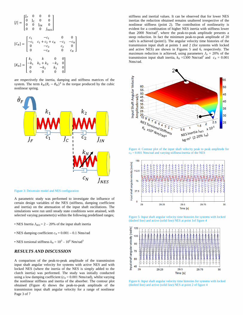
A comparison of the peak-to-peak amplitude of the transmission input shaft angular velocity for systems with active NES and with locked NES (where the inertia of the NES is simply added to the clutch inertia) was performed. The study was initially conducted using a low damping coefficient (cN = 0.001 Nms/rad), whilst varying the nonlinear stiffness and inertia of the absorber. The contour plot obtained (Figure 4) shows the peak-to-peak amplitude of the transmission input shaft angular velocity for a range of nonlinear
stiffness and inertial values. It can be observed that for lower NES inertias the reduction obtained remains unaltered irrespective of the nonlinear stiffness (point 2). The contribution of nonlinearity is evident for a combination of higher NES inertia with stiffness lower than 2000 Nm/rad3, where the peak-to-peak amplitude presents a steep reduction. In fact the minimum peak-to-peak amplitude of 20 rad/s is achieved (point1). The angular velocity time histories of the transmission input shaft at points 1 and 2 (for systems with locked and active NES) are shown in Figures 5 and 6, respectively. The maximum reduction is achieved, using parameters JN = 20% of the transmission input shaft inertia, kN =1300 Nm/rad3 and cN = 0.001 Nms/rad.
Figure 4: Contour plot of the input shaft velocity peak to peak amplitude for cN = 0.001 Nms/rad and varying stiffness/inertia of the NES
Figure 5: Input shaft angular velocity time histories for systems with locked (dashed line) and active (solid line) NES at point 1of figure 4
Figure 6: Input shaft angular velocity time histories for systems with locked (dashed line) and active (solid line) NES at point 2 of figure 4

Page 4 of 7
The performance of the NES damping is studied using the loss factor, η:
𝜂𝜂 = ∆𝑁𝑁2𝜋𝜋𝑁𝑁
(4)
∆𝐸𝐸 = ∮𝐹𝐹𝑐𝑐 𝑑𝑑𝑑𝑑 (5)
𝐸𝐸 = 14𝑘𝑘𝐼𝐼(𝜃𝜃𝐶𝐶 − 𝜃𝜃𝐼𝐼)4 (6)
where, ΔE is the energy loss per cycle, Fc is the damping torque, E is the maximum energy stored and (θc - θN) is the relative displacement between the clutch and the NES.
The nonlinear spring and damping torque for the two cases (active and locked NES) is shown in Figures 7 and 8. For the case, where the NES acts effectively, the nonlinear torque produced is clearly larger than when the NES exhibits small amplitude oscillations.
Figure 7: Nonlinear spring and damping torque at point 1 (contour plot of figure 4)
Figure 8: Nonlinear spring and damping torque at point 2 (contour plot of figure 4)
The offset along the cubic line (more evident in Figure 8) represents the dispersion of energy dissipation per cycle by the NES damper. Given that the torque in case 1 is significantly higher and the dissipated energy (Eq 5) depends on the relative velocity between the NES and the clutch, it can be concluded that at point 1 the energy dissipated per cycle by the NES damper is higher than at point 2. This is despite the maximum stored energy in case 1 being three orders of
magnitude higher than in case 2, the loss factor η = 0.003 (for point 1) compared with η = 0.0013 of point 2.
The damping coefficient was modified to cN = 0.1 Nms/rad and the parametric study was repeated for the same range of values as in the previous case. Contour plots were generated to identify the range of parameters, when the NES is seen to perform effectively.
Figure 9: Contour plot of the input shaft velocity peak to peak amplitude for cN = 0.1 Nms/rad and varying stiffness/inertia of the NES
As is shown by Figure 9, when cN = 0.1 Nms/rad the performance of the absorber changes significantly. The minimum peak-to-peak amplitude observed in this case is now 48 rad/s for JN = 20% of the transmission input shaft inertia and kN = 2100 Nm/rad3. The angular input shaft velocity time histories corresponding to the maximum amplitude reduction (point 1) and minimum amplitude reduction are respectively shown in Figures 10 and 11. The nonlinear spring and damping torque for point 1 is shown in Figure 12 with the brown line representing the spring torque and the area enclosed within the solid purple line showing the energy dissipated by the damper during loading and unloading.
Figure 10: Input shaft angular velocity time histories for locked (dashed line) and active (solid line) NES at point 1of figure 9

Page 5 of 7
Figure 11: Input shaft angular velocity time histories for locked (dashed line) and active (solid line) NES at point 2of figure 9
The loss factor in this case (cN = 0.1 Nms/rad) is η = 0.320 for point 1 and η = 0.042 for point 2. By comparing the two values it is concluded that at point 1 the energy dissipated per cycle by the NES damper is substantially higher than at point 2.
Figure 12: Nonlinear spring (solid line) and damping (dashed line) torque at point 1 (of figure 9)
The current study has shown the effect of damping introduced by a nonlinear vibration absorber and its ability to reduce vibrations at engine idling state. For the case of low damping coefficient (cN = 0.001 Nms/rad) it is observed that the most significant peak-to-peak amplitude reduction is obtained to be 82%, whilst the energy dissipated by the damper is fairly low (loss factor 0.003 at Table 2.). Conversely, in the system with a higher damping coefficient (cN = 0.1 Nms/rad) the energy dissipated per cycle is almost three orders of magnitude higher (a loss factor of 0.320), but the peak-to-peak amplitude reduction is 72%.
These results suggest that even though higher damping induces more energy dissipation through the NES damper, it does not necessarily result in the same level of reduction in the amplitude of oscillations of the primary system components. In general, higher damping dissipates a larger amount of system energy by limiting the relative displacement of the attachment, whereas in the case of low damping, this energy is stored by the nonlinear springs. On the other hand, high spring stiffness can block this relative motion. Thus, a large NES inertia can overcome the damping resistance, whilst allowing high relative displacement. This displays the NES interactions with the primary system. The latter is an indication of the NES performance. Furthermore, as simulation results have shown, the maximum torque produced by the NES with cN = 0.001 Nms/rad is 35 Nm (Figure 7), whereas the maximum torque produced for the NES with cN = 0.1
Nms/rad is only 25 Nm (Figure 12). This is observed in Figure 13, where the NES relative displacement (𝜽𝜽𝒄𝒄 − 𝜽𝜽𝒔𝒔) for cN = 0.001 Nms/rad is higher than that using cN = 0.1 Nms/rad.
Table 2: Loss factor comparison
Damping coefficient cN = 0.001 Nms/rad
Damping coefficient cN = 0.1 Nms/rad
Loss factor point 1 0.003 0.320
Loss factor point 2 0.0013 0.042
Figure 13: NES - clutch relative displacement comparison for low NES damping (solid line) and high NES damping (dashed line)
To confirm the previous conclusions the systems with locked and active NES were compared in terms of the peak-to-peak amplitudes of the input shaft velocity and the maximum percentage reduction, induced by the NES. This is then plotted as a function of the NES damping coefficient variation (Figure 14). It can be observed that as the damping coefficient increases, the percentage amplitude reduction decreases, indicating that even though more energy is dissipated at the NES damper, it actually stores less energy.
Figure 14: NES linear damping coefficient vs reduction of the input shaft velocity amplitude

Page 6 of 7
Conclusions and Future Work
The current study has successfully analysed the effect of damping on the NES capability to attenuate input shaft vibrations at the engine idle speed. The study has demonstrated the effectiveness of an NES in reducing vibrations of the primary system; mostly governed by the NES damping coefficient and its cyclic energy storage capability. Using computer simulations of a drivetrain model, coupled with an NES, it has been observed that a relatively light (and potentially compact) attachment can attenuate the vibration of the transmission input shaft. The size and weight of the NES are largely governed by the choice of structural material, the radius of rotation and the available space. As an example for an NES with a damping coefficient of cN = 0.1 Nms/rad, the required inertia is up to 10% of the transmission input shaft inertia (Figure 9). This equates to an NES of up to 1.0 kg mass. Similarly, in the study by Haris et al. [12] the required NES inertia was 11% of the transmission input shaft inertia. This would equate to an NES mass up to 0.5 kg. The difference in the NES mass in these studies is due to the inertia of the considered transmission input shaft. The transmission input shaft considered in [12] has a lower inertia than the one studied here. It is evident that the mass of the NES is indeed governed by the parameters of the studied application.
Nevertheless, the higher NES damping coefficient resulted in higher energy dissipation per cycle, but this condition directly reduces the NES capabilities of suppressing the primary system’s vibrations. Thus, the damping of the NES should be designed in relation to its ability to locally dissipate the energy, whilst oscillating extensively enabling it to capture the energy of the primary system. For future work, the aim of the investigation is to validate the numerical results by performing experimental testing, where the damping content of the NES can be varied.
References
1. Perera, M S M, Theodossiades, S and Rahnejat, H, 2007, 'A Multi-Physics Multi-Scale Approach in Engine Design Analysis', Proceedings of The Institution Of Mechanical Engineers, Part K: Journal Of Multi-Body Dynamics 221 (3): 335-348.
2. Koronias, G., Theodossiades, S., Rahnejat, H. and Saunders, T. 2011, 'Axle Whine Phenomenon in Light Trucks: A Combined Numerical and Experimental Investigation', Proceedings Of The Institution Of Mechanical Engineers, Part D: Journal Of Automobile Engineering 225 (7): 885-894.
3. Gnanakumarr, M., Theodossiades, S., and Rahnejat, H., "The Tribo-Contact Dynamics Phenomenon in Torsional Impact of Loose Gears - Promoting Gear Rattle", SAE Technical Paper 2002-01-2249, 2002, doi:10.4271/2002-01-2249.
4. Tangasawi, O, Theodossiades, S., Rahnejat, H. and Kelly, P. 2008, 'Non-Linear Vibro-Impact Phenomenon Belying Transmission Idle Rattle', Proceedings Of The Institution Of Mechanical Engineers, Part C: Journal Of Mechanical Engineering Science 222 (10): 1909-1923.
5. De la Cruz, M., Theodossiades, S., King, P. and Rahnejat, H. 2011, 'Transmission Drive Rattle With Thermo-Elastohydrodynamic Impacts: Numerical And Experimental Investigations', Int. J. Powertrains 1 (2): 137.
6. Yu Y, Naganathan NG, Dukkipati RV. “A literature review of automotive vehicle engine mounting systems”. Mechanism and Machine Theory. 2001; 36(1):123-42.
7. Jeong T, Singh R. “Analytical Methods of Decoupling the Automotive Engine Torque Roll Axis”. Journal of Sound and Vibration. 2000; 234:85-114.
8. Kelly, P., Rahnejat, H. and Biermann, J. W. "C553/013/98: Multi-body dynamics investigation of clutch pedal in-cycle vibration (whoop)." IMechE Conference Transactions, vol. 13, pp. 167-178. Mechanical Engineering Publications, 1998.
9. Reitz, A., J. W. Biermann, T. Schumacher, and P Kelly. "Special test benches to investigate driveline related NVH phenomena." In Proceedings of the Aachener Kolloquium Fahrzeug-und Motorentechnik. 1999.
10. Drexl H.J.,1987, “Torsional dampers and alternative systems to reduce driveline vibrations”. SAE paper, 870393.
11. Lee, Y.S., Vakakis; A.F., Bergman, L.A., McFarland, D.M. et al. “Passive non-linear targeted energy transfer and its applications to vibration absorption: A review”. Proc IMechE Part K: J Multi-body Dynamics. 2008; 222.
12. Haris A, Motato E, Theodossiades S, Vakakis A, Bergman L and McFarland D, Struve B,2015. “Targeted Energy Transfer in Automotive Powertrains”. Presented at the 13th International Conference Dynamical Systems - December 7-10, Lodz, Poland
13. Vakakis, A.F., Gendelman, O.V., Bergman, L.A., McFarland, D.M. et al., Nonlinear targeted energy transfer in mechanical and structural systems: Springer Science & Business Media; 2008.
14. Gendelman,O.V., Sapsis, T., Vakakis, A.F., Bergman, L.A. “Enhanced passive targeted energy transfer in strongly nonlinear mechanical oscillators”. Journal of Sound and Vibration. 2011; 330:1-8.
15. Gendelman, O.V. “Transition of energy to a nonlinear localized mode in a highly asymmetric system of two oscillators”. Nonlinear Dynamics. 2001; 25:237-53.
16. Vakakis, A.F. “Inducing Passive Nonlinear Energy Sinks in Vibrating Systems”. Journal of Vibration and Acoustics/Transactions of the ASME 2001; 123:324-32.
17. Hubbard, S.A., McFarland, D.M., Bergman, L.A., Vakakis, A.F. “Experimental Targeted Energy Transfer to a Rotary Nonlinear Energy Sink”. 51st AIAA/ASME/ASCE/AHS/ASC Structures, Structural Dynamics, and Materials Conference 18th AIAA/ASME/AHS Adaptive Structures Conference 12th2010. p. 3045.
18. Kerschen, G., Lee, Y.S., Vakakis, A.F., McFarland, D.M., et al. “Irreversible passive energy transfer in coupled oscillators with essential nonlinearity”. SIAM Journal on Applied Mathematics. 2005; 66(2):648-79
19. Sigalov, G., Gendelman, O., Al-Shudeifat, M., Manevitch, L. et al. “Resonance captures and targeted energy transfers in an inertially-coupled rotational nonlinear energy sink”. Nonlinear Dynamics. 2012; 69(4):1693-704.
20. Viguié, R., Kerschen, G., Golinval, J.C., McFarland D. et al. “Using passive nonlinear targeted energy transfer to stabilize drill-string systems”. Mechanical Systems and Signal Processing. 2009; 23(1):148-69.
21. Wang, D., Lee, Y., McFarland, D., Bergman, L. et al. “Mitigating the effect of impact loading on a vehicle using an essentially nonlinear absorber”. Vehicle System Dynamics. 2009; 47(10):1183-204.
22. Luo, J., Wierschem, NE., Hubbard, S.A., Fahnestock, L.A. et al. “Large-scale experimental evaluation and numerical simulation of a system of nonlinear energy sinks for seismic mitigation”. Engineering Structures. 2014; 77:34-48.
23. Wang, J., Wierschem, N., Spencer, B.F., Lu, X. “Experimental study of track nonlinear energy sinks for dynamic response reduction”. Engineering Structures. 2015; 94:9-15.
24. Al-Shudefait M, Vakakis A and Bergman L. A., (2016). Shock Mitigation by Means of Low to high frequency Nonlinear Targeted Energy Transfer in a Large-Scale Structure. Accepted

Page 7 of 7
for Publication, ASME Journal of Computational and Nonlinear Dynamics
Contact Information
Kelly Savva – [email protected]
Ahmed Haris – [email protected]
Eliot Motato – [email protected]
Mahdi Mohammad-Pour – [email protected]
Stephanos Theodossiades – [email protected]
Homer Rahnejat – [email protected]
Patrick Kelly - [email protected]
Alexander F Vakakis – [email protected]
Lawrence Bergman - [email protected]
Donald McFarland - [email protected]
Acknowledgments
The authors wish to express their gratitude to the EPSRC for the financial support extended to the “Targeted energy transfer in powertrains to reduce vibration-induced energy losses” Grant (EP/L019426/1), under which this research was carried out. Thanks are also due to Ford Motor Company and Raicam Clutch for their technical support.
Abbreviations
DMF Dual Mass Flywheel
NES Nonlinear Energy Sink
TET Targeted Energy Transfer
NVH Noise Vibration and Harshness
CPVA Centrifugal Pendulum Vibration Absorbers
TRA Torque Roll Axis
VI Vibro Impact