Embed Size (px)
Citation preview
Industrial Air Technology Corp. 1
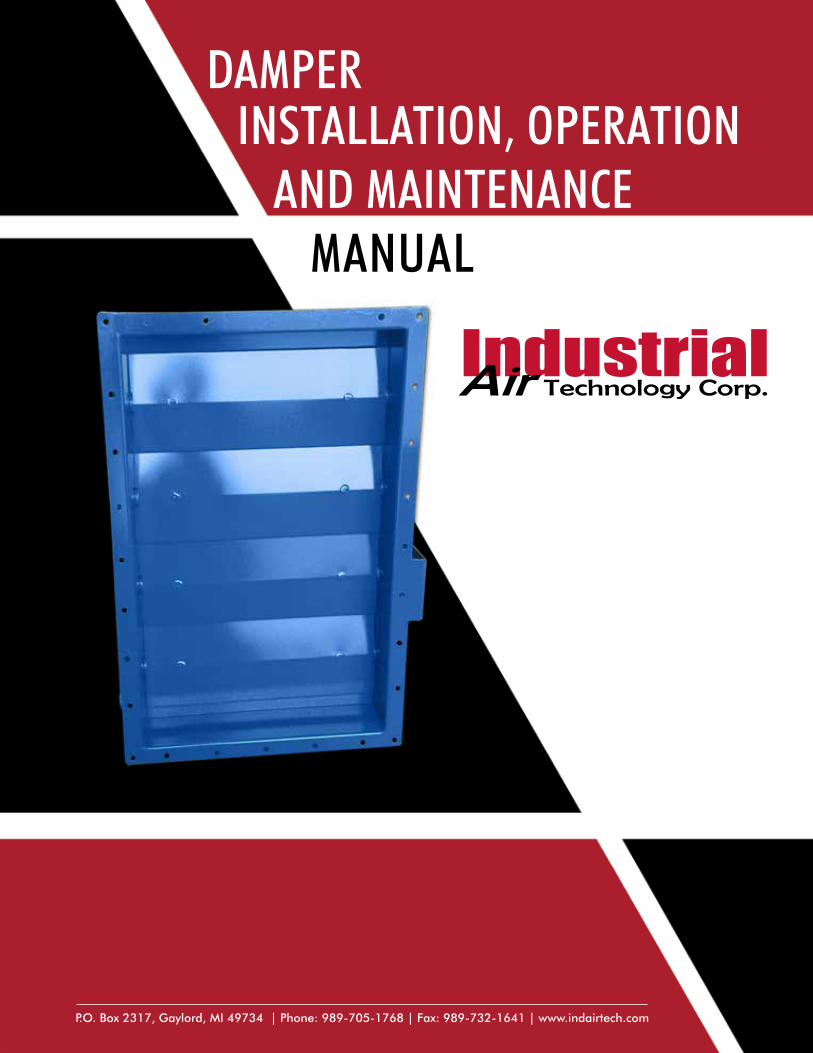
DAMPERINSTALLATION, OPERATION
AND MAINTENANCEMANUAL
P.O. Box 2317, Gaylord, MI 49734 | Phone: 989-705-1768 | Fax: 989-732-1641 | www.indairtech.com
2 Industrial Air Technology Corp.
1. GENERAL INFORMATION Industrial Air Technology Corp. dampers are designed for continuous duty in an industrial environment. They are engineered for predictable performance and trouble-free operation. Each damper is thoroughly inspected by trained factory personnel prior to shipping. When properly installed and maintained, the damper will be trouble free. This manual applies to all Industrial Air Technology Corp. dampers. Specially engineered dampers for unique applications may require additional instructions and will be included with the damper. Improper installation, modification, service or maintenance can lead to property damage, injury or death. Thoroughly read and adhere to the instructions in this manual and retain this manual with the damper for future reference.
2. SAFETY
The responsibility for providing safety accessories for Industrial Air Technology Corp. supplied equipment is that of the installer and user of the equipment.
WARNING
Dampers actuated by powered actuators (electric, pneumatic, hydraulic, etc.) must be reviewed for safety guarding of the moving parts on the damper, and actuator itself. The need for guarding of linkage, blades, and actuator components should be evaluated based on the specific installation at the end user’s facility. Where inlets and outlets are not ducted, screens are strongly recommended. Users and installers of this equipment should carefully read all accompanying literature pertaining to safe operation.
Industrial Air Technology Corp. dampers are designed to provide a long, trouble-free life, but do require maintenance and inspection as described in this manual.
WARNING
When maintenance is required, it is critical that these safety precautions are followed:
1. Turn off / disconnect all electrical and/or pneumatic connections.
2. Lock out electric and/or pneumatics.
3. Block damper blades or attach crane to prevent movement.
4. Be careful when removing heavy components (actuator, bearings, air cylinders, etc.)
Failure to follow these precautions could result in personal injury or damage to equipment.
3. RECEIVING AND INSPECTION All dampers ship f.o.b. from Gaylord, MI. Dampers are prepared for shipment according to the uniform freight classification rules of the carriers. The equipment is carefully inspected before shipment and it is the responsibility of the carrier that it is in perfect condition upon arrival.
When the carrier accepts a shipment and signs the bill of lading, the carrier becomes responsible for any subsequent shortages or damage, evident or concealed, and any claim must be made against the carrier.
Immediately upon receipt of a shipment, carefully inspect equipment for damage and shortage. If any damage and/or shortage is detected or suspected, the carrier must be asked to conduct an inspection. The consignee’s representative should not accept shipment without making a notation on the delivery receipt, indicating items not delivered or the apparent extent of damage.
When a shipment is opened and damage is found which was not evident externally (“concealed damage”), it is mandatory that the consignee request an immediate inspection by the carrier. Promptly file a claim against the final carrier.
4. HANDLINGThe damper should only be lifted by the flanges or lifting eyes provided for on the damper assembly. Never lift a damper by the blade(s), shaft, actuator or any damper part not designed for lifting. Lifting decisions must be left to trained personnel. Fork Lift/Crane capacity must be checked for sufficient lifting capacity. Dampers which are furnished with special coverings such as rubber, phenolic enamels, or other protective coatings, should be handled with extreme care as many of these coatings are easily damaged. Even a small chipped spot will break the continuity of the coating and destroy its value as a protective covering of the metal.
5. STORAGEDampers stored for any period of time before installation must be protected from dirt and moisture. Dampers should be stored on pallets and not directly on the ground or on concrete. They may be stacked with wood or spacers between flanges, do not allow damper to be supported by the blades. Never store with axels vertical. Ideally dampers should be stored inside, but if they must be stored outside use of a breathable tarp to cover the unit will aid in keeping it clean and dry. Do not use a black plastic tarp, as it will promote condensation.
For long term or outdoor storage (not recommended), the bearings should be purged monthly with new grease to remove condensation. Rotate the damper blades by hand at least once every two weeks to prevent the bearings from “setting” and in order to redistribute the grease on the bearing parts. The damper must be isolated from any near-by vibration. High over all vibration levels in the damper storage area may prematurely damage the damper and/or actuator.
Before startup following extended storage, purge the bearings with new grease.
1. General Information 2. Safety 3. Receiving and Inspection 4. Handling 5. Storage 6. Installation
Contents 7. Start Up 8. Maintenance 9. Troubleshooting 10. Field Service 11. Limited Warranty
Industrial Air Technology Corp. 3
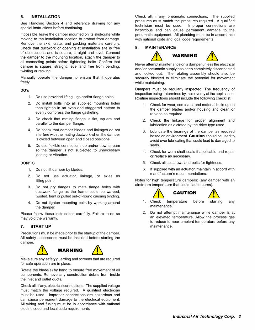
6. INSTALLATION See Handling Section 4 and reference drawing for any special instructions before continuing.
If possible, leave the damper mounted on its skid/crate while moving to the installation location to protect from damage. Remove the skid, crate, and packing materials carefully. Check that ductwork or opening at installation site is free of obstructions and is square, straight and level. Connect the damper to the mounting location, attach the damper to all connecting points before tightening bolts. Confirm that damper is square, straight, level and free from bending, twisting or racking.
Manually operate the damper to ensure that it operates freely.
DO’s1. Do use provided lifting lugs and/or flange holes.
2. Do install bolts into all supplied mounting holes then tighten in an even and staggered pattern to evenly compress the flange gasketing.
3. Do check that mating flange is flat, square and parallel to the damper flange.
4. Do check that damper blades and linkages do not interfere with the mating ductwork when the damper is cycled between open and closed positions.
5. Do use flexible connections up and/or downstream so the damper is not subjected to unnecessary loading or vibration.
DON’TS1. Do not lift damper by blades.
2. Do not use actuator, linkage, or axles as lifting point.
3. Do not pry flanges to mate flange holes with ductwork flange as the frame could be warped, twisted, bent or pulled out-of-round causing binding.
4. Do not tighten mounting bolts by working around the damper.
Please follow these instructions carefully. Failure to do so may void the warranty.
7. START UPPrecautions must be made prior to the startup of the damper. All safety accessories must be installed before starting the damper.
WARNING
Make sure any safety guarding and screens that are required for safe operation are in place.
Rotate the blade(s) by hand to ensure free movement of all components. Remove any construction debris from inside the inlet and outlet ducts.
Check all, if any, electrical connections. The supplied voltage must match the voltage required. A qualified electrician must be used. Improper connections are hazardous and can cause permanent damage to the electrical equipment. All wiring and fusing must be in accordance with national electric code and local code requirements
Check all, if any, pneumatic connections. The supplied pressures must match the pressures required. A qualified technician must be used. Improper connections are hazardous and can cause permanent damage to the pneumatic equipment. All plumbing must be in accordance with national code and local code requirements.
8. MAINTENANCE
WARNING
Never attempt maintenance on a damper unless the electrical and/ or pneumatic supply has been completely disconnected and locked out. The rotating assembly should also be securely blocked to eliminate the potential for movement while maintaining.
Dampers must be regularly inspected. The frequency of inspection being determined by the severity of the application. Routine inspections should include the following checklist:
1. Check for wear, corrosion, and material build up on the damper blades and/or housing and clean or replace as required.
2. Check the linkage for proper alignment and lubrication as dictated by the drive type used.
3. Lubricate the bearings of the damper as required based on environment. Caution should be used to avoid over lubricating that could lead to damaged to seals.
4. Check for worn shaft seals if applicable and repair or replace as necessary.
5. Check all setscrews and bolts for tightness.
6. If supplied with an actuator, maintain in accord with manufacturer’s recommendations.
Notes for high temperature dampers: (any damper with an airstream temperature that could cause burns).
CAUTION
1. Check temperature before starting any maintenance.
2. Do not attempt maintenance while damper is at an elevated temperature. Allow the process gas to reduce to near ambient temperature before any maintenance.
4 Industrial Air Technology Corp.
9. TROUBLESHOOTINGManually actuated damper’s blade(s) do not move:
1. Ensure damper is free of obstructions.
2. Check the linkage for binding.
3. Check that the damper is installed correctly as any twist or bend in the frame of the damper could prohibit smooth operation.
Electrically actuated dampers:
1. Actuator not responding.
A. Make sure the actuator is wired correctly and receiving the correct voltage.
B. Check limit switches to make sure they are set correctly.
C. If equipped with a manual override, check operation of handwheel. Confirm that clutch is engaging and/ or disengaging correctly.
D. Remove actuator from damper and check if it operates properly and that the amp draw is normal.
2. Actuator is operating, but blade(s) fail to move or only move limited distance.
A. Ensure damper is free of obstructions.
B. Check linkage for binding.
C. Check that the damper is installed correctly as any twist or bend in the frame of the damper could prohibit smooth operation.
D. Make sure that limit switches in the actuator are set correctly.
E. Make sure that end travel of the actuator is set correctly.
For more information see actuator manufacturer manual.
Pneumatically actuated dampers:
1. Actuator not responding.
A. Make sure the actuator is connected correctly and receiving the correct pressure.
B. Check limit switches to make sure they are set correctly.
C. If equipped with manual override, check operation of handwheel. Confirm that clutch is engaging and/or disengaging correctly.
D. Remove actuator from damper and check if it operates properly.
2. Actuator is operating, but blade(s) fail to move or only move limited distance.
A. Check that the damper is free of obstructions.
B. Check linkage for binding.
C. Check that the damper is installed correctly as any twist or bend in the frame of the damper could prohibit smooth operation.
D. Make sure that limit switches in the actuator are set correctly.
E. Make sure that end travel of the actuator is set correctly.
For more information see actuator manufacturer manual.
10. FIELD SERVICEField service such as on site assembly supervision, start up assistance, trouble shooting, repair, or balancing can be provided and purchased thru qualified third party personnel. Industrial Air Technology Corp. can assist you in aligning with these third parties. Contact IATC at 989-705-1768 for assistance.
11. LIMITED WARRANTYThe Seller warrants products of its own manufacture, against defects of material and workmanship under normal use and service for a period of eighteen (18) months from date of shipment or twelve (12) months from date of installation, whichever occurs first. This warranty does not apply to any Industrial Air Technology products and parts which have failed as a result of faulty installation or abuse, or incorrect electrical connections or alterations, made by others, or use under abnormal operating conditions or misapplication of the products and parts. Expenses incurred by Purchaser in repairing or replacing any defecting product will not be covered except where authorized in writing and signed by an officer of the Seller. Our obligation under the Warranty is limited to repairing or replacing (or allowing credit), at our option, without cost to the Purchaser, at our factory any part or parts thereof which shall, within such warranty period, be returned to us with transportation charges prepaid, and which our examination shall disclose to our satisfaction to have been defective. On equipment furnished by the Seller, but manufactured by others, such as motors and bearings, Seller extends the same warranty as Seller receives from the manufacturer thereof. Seller assumes no responsibility for material returned to our plant without our written permission.
Industrial Air Technology Corp. 5
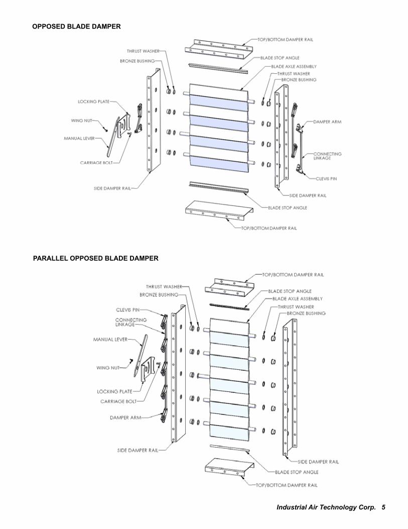
OPPOSED BLADE DAMPER
PARALLEL OPPOSED BLADE DAMPER
6 Industrial Air Technology Corp.
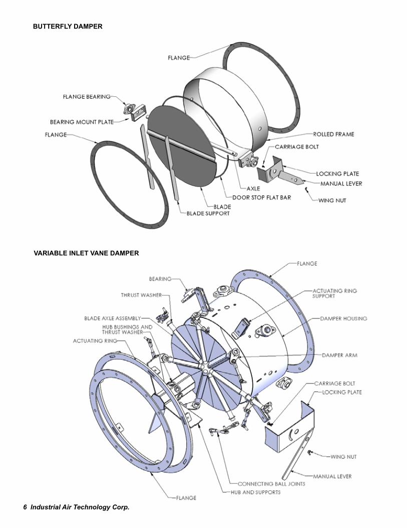
BUTTERFLY DAMPER
VARIABLE INLET VANE DAMPER

Industrial Air Technology Corp. 7

8 Industrial Air Technology Corp. P.O. Box 2317, Gaylord, MI 49734 | Phone: 989-705-1768 | Fax: 989-732-1641 | www.indairtech.com