Embed Size (px)
Citation preview
1 of 14
Damage Tolerance of Tow-Placed, Variable-Stiffness Laminates
Damage Tolerance of Tow-Placed, Variable Stiffness Laminates
17 November 2005
Cláudio Lopes
Zafer GürdalDelft University of Technology
AndPedro Camanho
Faculdade de Engenharia da Universidade do Porto
work supported by:
2 of 14
Damage Tolerance of Tow-Placed, Variable-Stiffness Laminates
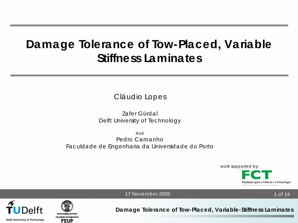
Main Goal
Development of methodologies to predict the structural integrity of fibre-
steered laminates
Experimental Investigation
• Material testing
• Progressive damage leading to structural collapse
• Structural damage produced by low-velocity impacts
Numerical Simulations
• Physically-based constitutive models able to represent
damage onset, progress and failure
• Finite Element Analysis
• Micromechanical models
3 of 14
Damage Tolerance of Tow-Placed, Variable-Stiffness Laminates
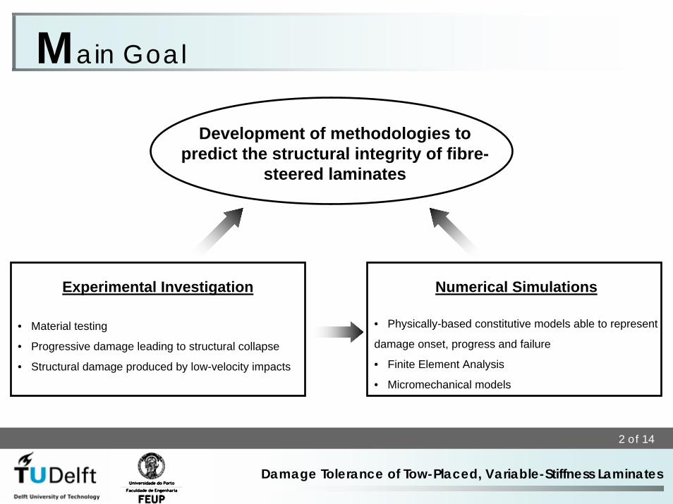
Tow-Placed, Variable-Stiffness LaminatesTow- Placement Technology
Tow-Placement Systems(e.g. Cicinnati, Hercules, Automated Dynamics)
• 7 degrees of freedom
• Full automation
• Off-line programming and simulation
• Fabrication of parts over 10m in length
• Multi-purpose tow-placement head
4 of 14
Damage Tolerance of Tow-Placed, Variable-Stiffness Laminates
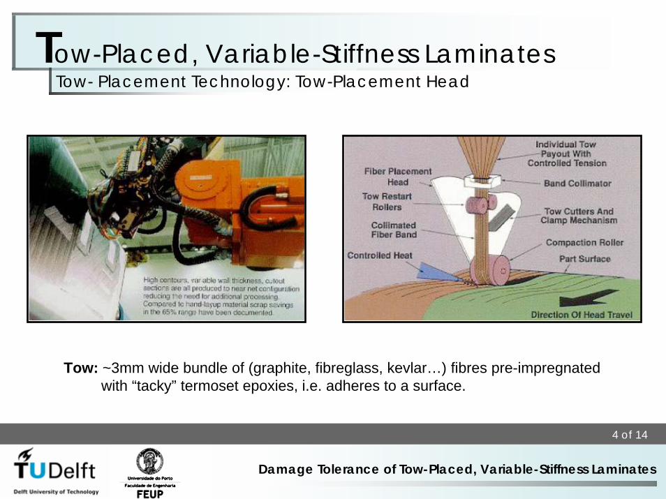
Tow-Placed, Variable-Stiffness LaminatesTow- Placement Technology: Tow-Placement Head
Tow: ~3mm wide bundle of (graphite, fibreglass, kevlar…) fibres pre-impregnated with “tacky” termoset epoxies, i.e. adheres to a surface.
5 of 14
Damage Tolerance of Tow-Placed, Variable-Stiffness Laminates
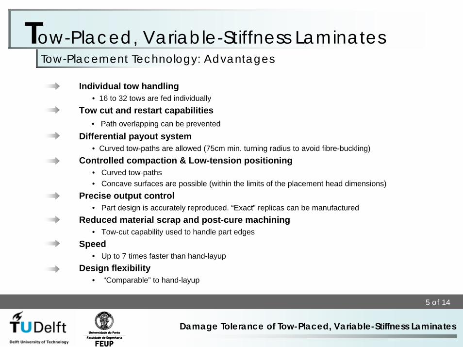
Tow-Placed, Variable-Stiffness LaminatesTow-Placement Technology: Advantages
Individual tow handling• 16 to 32 tows are fed individually
Tow cut and restart capabilities• Path overlapping can be prevented
Differential payout system• Curved tow-paths are allowed (75cm min. turning radius to avoid fibre-buckling)
Controlled compaction & Low-tension positioning• Curved tow-paths • Concave surfaces are possible (within the limits of the placement head dimensions)
Precise output control• Part design is accurately reproduced. “Exact” replicas can be manufactured
Reduced material scrap and post-cure machining• Tow-cut capability used to handle part edges
Speed• Up to 7 times faster than hand-layup
Design flexibility• “Comparable” to hand-layup
6 of 14
Damage Tolerance of Tow-Placed, Variable-Stiffness Laminates
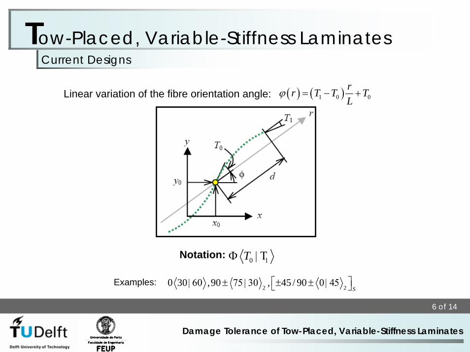
Tow-Placed, Variable-Stiffness LaminatesCurrent Designs
Linear variation of the fibre orientation angle: ( ) ( )1 0 0rr T T TL
ϕ = − +
0T 1Φ | ΤNotation:
2 20 30 ,90 , 45 / 90 0
S⎡ ⎤| 60 ± 75 | 30 ± ± | 45⎣ ⎦Examples:
7 of 14
Damage Tolerance of Tow-Placed, Variable-Stiffness Laminates
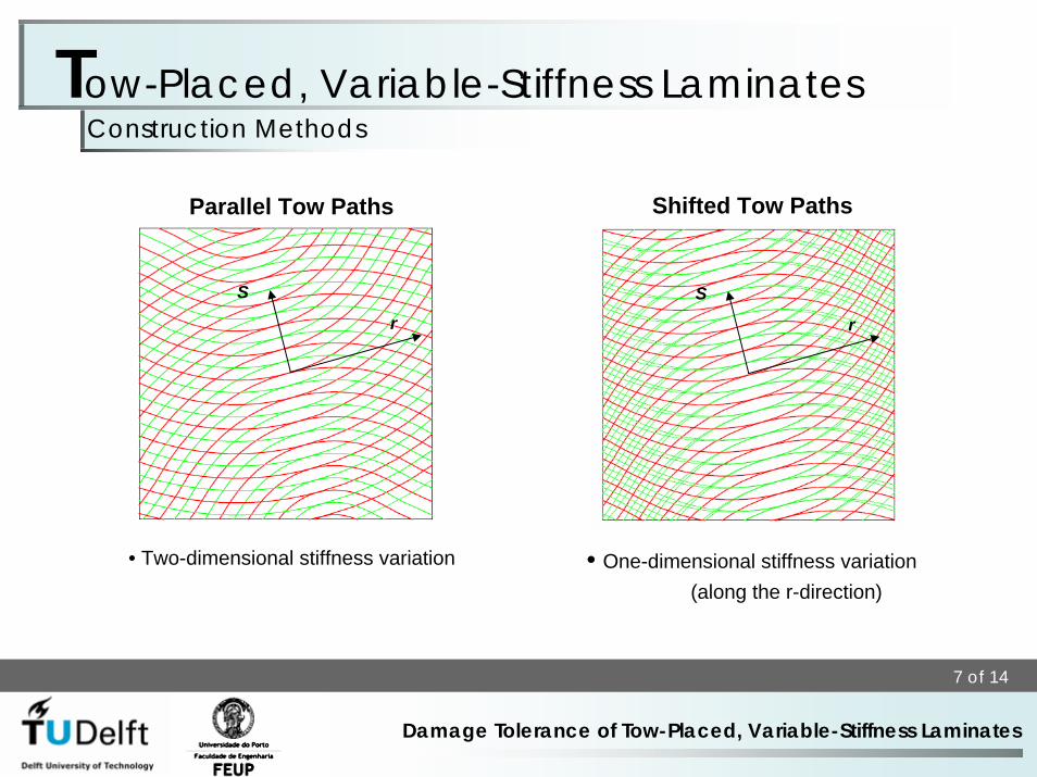
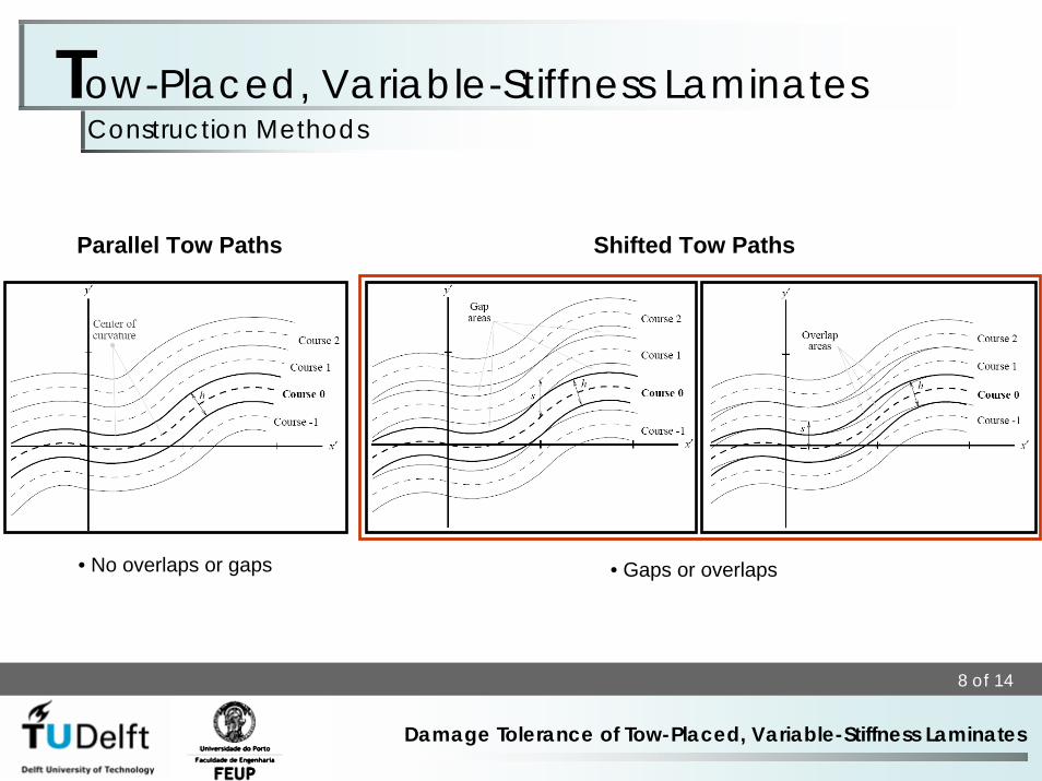
Tow-Placed, Variable-Stiffness LaminatesConstruction Methods
• Two-dimensional stiffness variation • One-dimensional stiffness variation (along the r-direction)
Shifted Tow PathsParallel Tow Paths
r
Sr
S
8 of 14
Damage Tolerance of Tow-Placed, Variable-Stiffness Laminates
Tow-Placed, Variable-Stiffness LaminatesConstruction Methods
Shifted Tow PathsParallel Tow Paths
• No overlaps or gaps • Gaps or overlaps
9 of 14
Damage Tolerance of Tow-Placed, Variable-Stiffness Laminates
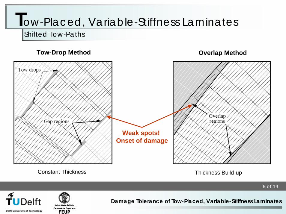
Tow-Placed, Variable-Stiffness LaminatesShifted Tow-Paths
Overlap MethodTow-Drop Method
Constant Thickness Thickness Build-up
Weak spots! Onset of damage
10 of 14
Damage Tolerance of Tow-Placed, Variable-Stiffness Laminates
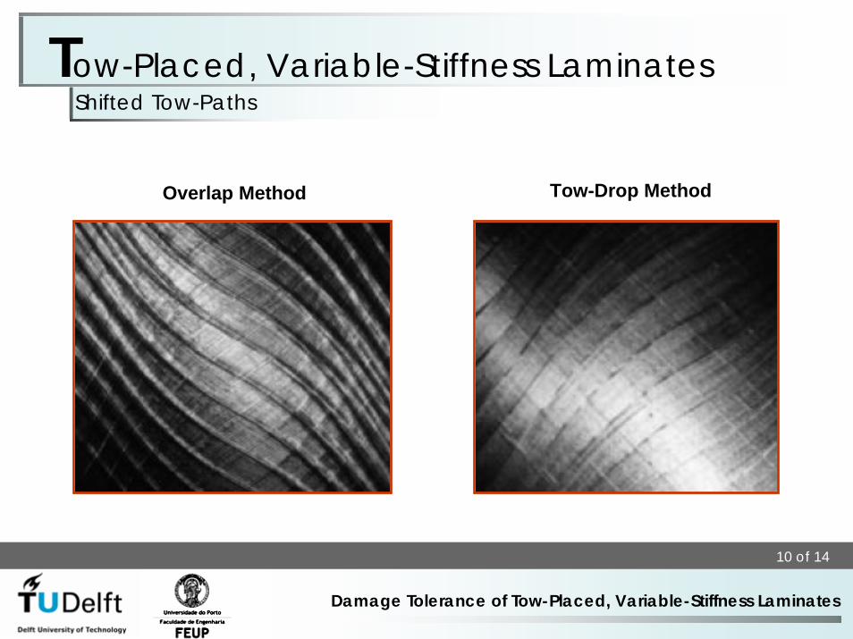
Overlap Method Tow-Drop Method
Tow-Placed, Variable-Stiffness LaminatesShifted Tow-Paths
11 of 14
Damage Tolerance of Tow-Placed, Variable-Stiffness Laminates
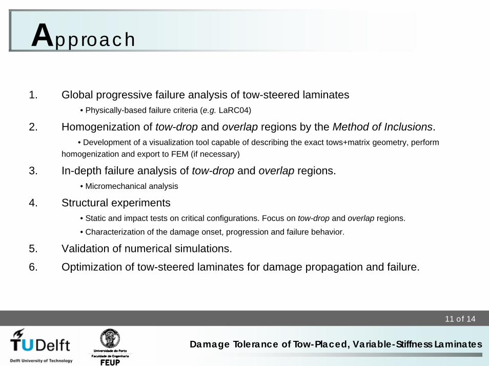
1. Global progressive failure analysis of tow-steered laminates• Physically-based failure criteria (e.g. LaRC04)
2. Homogenization of tow-drop and overlap regions by the Method of Inclusions.• Development of a visualization tool capable of describing the exact tows+matrix geometry, perform
homogenization and export to FEM (if necessary)
3. In-depth failure analysis of tow-drop and overlap regions.• Micromechanical analysis
4. Structural experiments• Static and impact tests on critical configurations. Focus on tow-drop and overlap regions.
• Characterization of the damage onset, progression and failure behavior.
5. Validation of numerical simulations.
6. Optimization of tow-steered laminates for damage propagation and failure.
Approach
12 of 14
Damage Tolerance of Tow-Placed, Variable-Stiffness Laminates
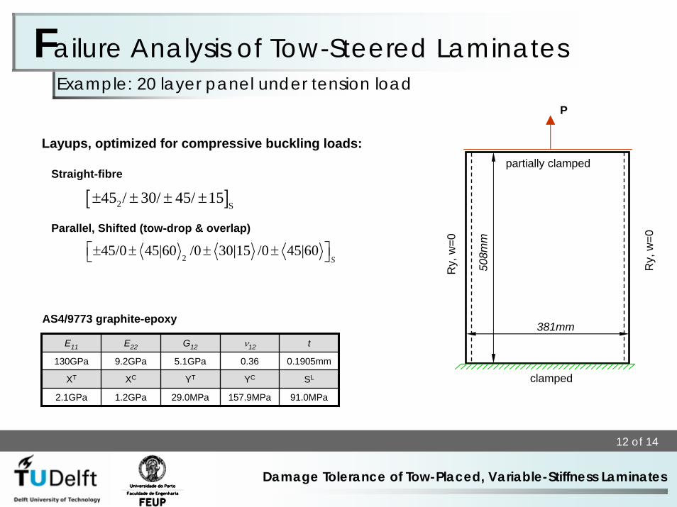
Layups, optimized for compressive buckling loads:
Straight-fibre
Parallel, Shifted (tow-drop & overlap)
Example: 20 layer panel under tension load
381mm
508m
m
clamped
Ry,
w=0
Ry,
w=0
partially clamped
Failure Analysis of Tow-Steered Laminates
E11 E22 G12 ν12 t
130GPa 9.2GPa 5.1GPa 0.36 0.1905mm
XT XC YT YC SL
2.1GPa 1.2GPa 29.0MPa 157.9MPa 91.0MPa
245/0 45|60 /0 30|15 /0 45|60
S⎡ ⎤± ± ± ±⎣ ⎦
[ ]2 S45 / 30/ 45/ 15± ± ± ±
P
AS4/9773 graphite-epoxy
13 of 14
Damage Tolerance of Tow-Placed, Variable-Stiffness Laminates
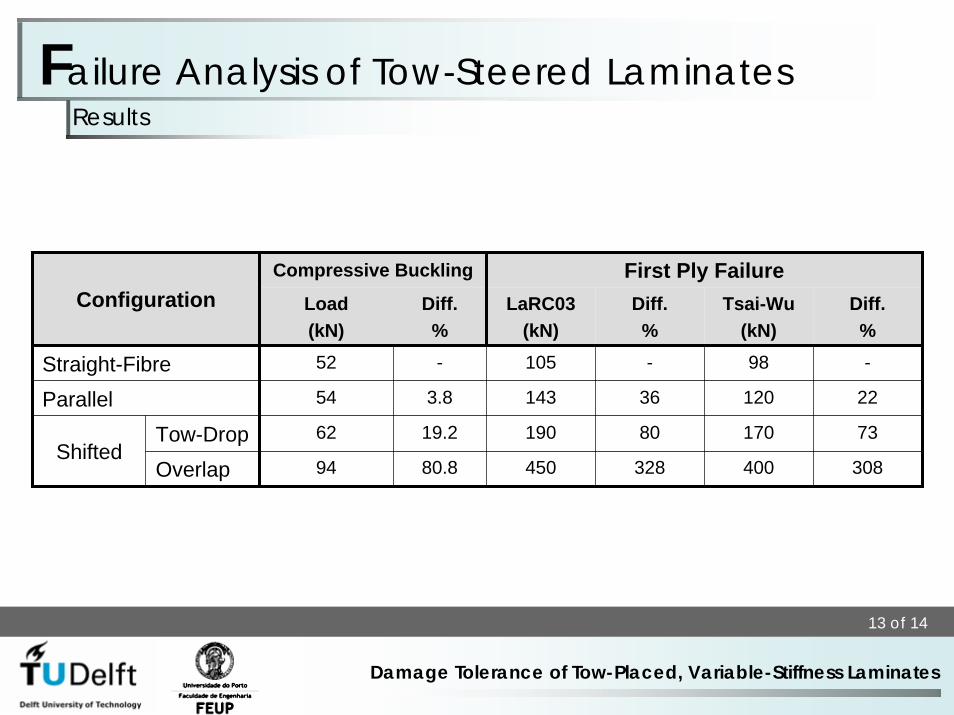
Failure Analysis of Tow-Steered LaminatesResults
Compressive Buckling First Ply FailureConfiguration Load
(kN)Diff.%
LaRC03(kN)
Diff.%
Tsai-Wu(kN)
Diff.%
- -
22
Tow-Drop 73
Overlap 308
36
80
328
98
120
170
400
52 -
54 3.8
19.2
80.8
62
94
105
143
190
Straight-FibreParallel
Shifted450
14 of 14
Damage Tolerance of Tow-Placed, Variable-Stiffness Laminates
Damage Tolerance of VS LaminatesAcknowledgements
Financiamento FCT/POCI
União EuropeiaFEDER
Governo da República Portuguesa