Embed Size (px)
Citation preview
Damage Effects of Pile Driving Vibration JOHN F. WISS, Wiss, Janney, Elstner and Assoc.
•PILE DRIVING, like dynamite blasts, nuclear blasts, and sonic booms, is a source of vibration which is frequently alleged to cause damage to structures. Unlike blasts, however, pile driving vibrations are produced by mechanical energy that is limited by the capabilities of the mechanical system. For example, a 5, 000-lb ram falling freely from a height of 3 ft cannot deliver more than 15, 000 ft-lb of energy on impact. Similarly, the maximum energy available from a double-acting steam hammer is limited by the steam pressure, the area of the piston, and the stroke.
On impact, the energy of the ram is imparted to the pile. It is distributed between rebound of the ram, elastic distortion of the pile, elastic and plastic deformation of ·the cushioning material, penetration of the pile, and elastic and plastic deformation of the earth surrounding the pile. The elastic deformation of the soil is propagated through the earth materials as elastic waves. The distribution of the available impact energy to the sources previously mentioned consists of interrelated functions, but the most important factor is the resistance of the soil to penetration by the pile. In a soft, easily penetrated soil, most of the energy is used in advancing the pile, and U1e least amount in the elastic deformation of the soil. In very hard, resistant soil the converse is true .
It is convenient to visualize the wave motion at the surface of the earth as being similar to the ripples produced on a smooth surface of water when a stone is thrown in. The wave length of the earth waves from pile driving is approximately 200 ft; this is the distance from the crest of one wave to the crest of the succeeding wave. Structures supported on the surface ride such waves in the same manner as a cork or box floating on the ripples of the water. Deeply embedded structures respond to a lesser degree in proportion to the orbital diameter of the earth particle motion which decreases exponentially with depth. For example, a structure embedded 200 ft below the surface would receive virtually no vibration. One at 100 ft would receive Yazth of the vibration experienced by a point on the surface. Regardless of depth, the magnitude of vibration intensity varies with the amount of energy transmitted to the soil, the physical properties of the soil, and the distance that the wave has traveled from the source.
Many instruments are capable of measuring the vibration intensities resulting from pile driving. Basically, such systems consist of a vibration sensor which converts the 1.1hy1:1ica.l motion of the earth or structure into electrical signals. These in turn are sufficiently strengthened by an electronic amplifier to drive a galvaniometer and produce a recording of vibration vs time. It is essential to record the vibration, because the impulses are transient, and the response of meters is not fast enough to follow the vibrations accurately. It is also important to record simultaneously the vibratory motion in three mutually perpendicular directions. Although the impact force is generally in the vertical direction, the maximum earth or structural vibration is not necessarily vertical.
The instrument most commonly used for measurement of earth or structural vibration resulting from pile driving is the portable tlu·ee-component seismograph. This unit is a mechanical optical system which utilizes seismic principles, is portable and battery operated, and produces a recording of displacement in three mutually perpendicular directions vs time. It is ideally suited for field recordings of the vibrations associated with pile driving.
Paper sponsored by Committee on Construction Practices-Structures and presented at the 45th Annual Meeting.
14
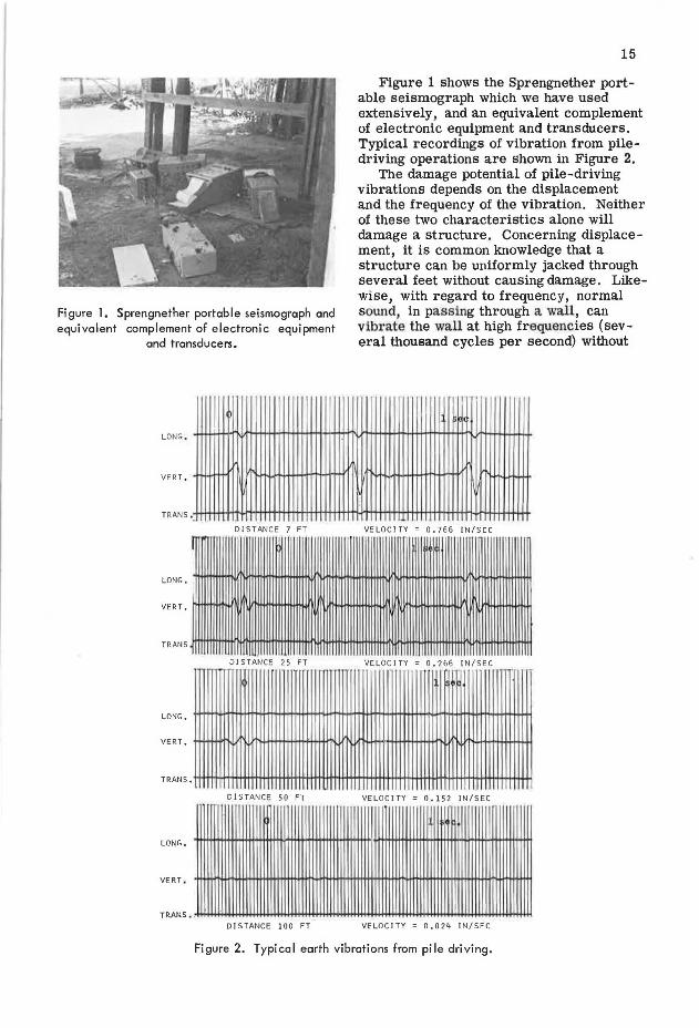
Figure l. Sprengnether portable seismograph and equivalent complement of electronic equipment
and transducers.
VERT,
LONG,
VERT,
TRANS
DISTANCE 25 FT .~ ......... ~... ~ ·"-~'"'-·
LONG,
VERT. ff+.!++f1"1,L.1~U.i'N+-+1+1.-i1+1+m1.<
DISTANCE 50 FT
VERT .
DISTANCE 10 0 FT
15
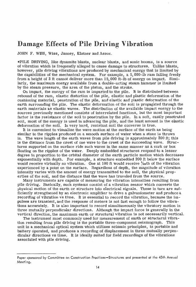
Figure 1 shows the Sprengnether portable seismograph which we have used extensively, and an equivalent complement of electronic equipment and transducers. Typical recordings of vibration from piledriving operations are shown in Figure 2.
The damage potential of pile-driving vibrations depends on the displacement and the frequency of the vibration. Neither of these two characteristics alone will damage a structure. Concerning displacement, it is common knowledge that a structure can be uniformly jacked through several feet without causing damage. Likewise, with regard to frequency, normal sound, in pas sing through a wall , can vibrate the wall at high frequencies (several thousand cycles per second) without
.
VELOCITY = 0,266 IN/SEC
VELOCITY = 0.152 IN/SEC
VELOCITY = 0.024 IN/SEC
Figure 2. Typical earth vibrations from pile driving.
r T •I -mI-.----0t~I ;/'"i°\
CJ "
A : AMPLITUDE OR DISP LACEMEN T (INCHES)
T • TIME (SECmJDS) FOR ONE CYC LE
f FREQUENCY ( CPS) = 1/ T
V = PAR T IC LE VEL OCITY (INCH ES ' E R SECOND)
v 2nfA
TYPICAL SOIL FREQUENCIES
(PILE DRIVINC. )
ALL UV I AL F IL L 5 -1 0 CPS
CLAY 1 5 -25 CPS
SAND 30 - 40 CP S
Figure 3. Particle velocity in alluvial Fill, clay, enc! send.
10 .0
9.0
(.) 8.0 LLJ (/)
' ~
7. 0
I
>- 6.0
!:::: (.) 0 5.0 _J
LLJ > 4 .0
LLJ _J (.) 3 .0
I-a: ~ 2 .0 a.
1. 0
0
SERIOUS CRACKING
CRACK JN<;
FINE CRACKS &
FALL OF LSE ~LASTER
CAUTION
NO NOTICEABLE
DAMAGE
LANGE FORS !SWEDE NJ
DAl1AGE
CAUTION
SAFE LU11T
EDWARDS ICANf-DAJ
~AJ•JR l'At'AGE
(FALL OF PLASTER, SER1nus CRACKING)
~ DAMAC-E (FHIE PLASTER CRAO:S, OPE~!HJC:
OF OLD CRACKS)
Cf,UTI ON
S AFE
BUM IN ES !U.S.A.)
10.0
9.0
8.0
7.0
6 .0
5 .0
4 .0
3.0
2.0
LO
0
Figure 4. Com;:icrison of damage criteria, residential-type structures.
..... 0)
e.o PLASTER CRACKS (RESIDENCES)
I RECOMMENDED SAFE LEVEL
(RESIDENCES)
u 7 m 1.01-------+---+-----//~ ,, _______ -1
' z // ~ o.e 1--------+---+----/ 7 g ~l ~ I /'11
d ~II :r 0.1 !----- 4/- 1_1 _____ -t-
~ ~¢_~_#:~1 ,_11_/-+---------1~
/ / //
"" I •I
ct; I
I
VENERGY - FT LB DISTANCE - FT
OBJECTIOtlABLE
0 IS TURB I NG
UNPLEASANT
WELL NOTICEABLE
PERCEPT! BLE
IMPERCEPTIBLE
17
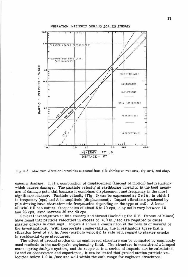
Figure 5. Maximum vibration intensities expected from pile driving on wet sand, dry sand, and clay.
causing damage. It is a combination of displacement (amount of motion) and frequency which causes damage. The particle velocity of earthborne vibration is the best measure of damage potential because it combines displacement and frequency in the moi::t significant manner. Particle velocity (Fig. 3) can be expressed as 2 TTfA, in which f is frequency (cps) and A is amplitude (displacement). Impact vibrations produced by pile driving have characteristic freque.1cies depending on the type of soil. A loose alluvial fill has natural frequencies of about 5 to 10 cps, clay soils vary between 15 and 25 cps, sand between 30 and 40 cps.
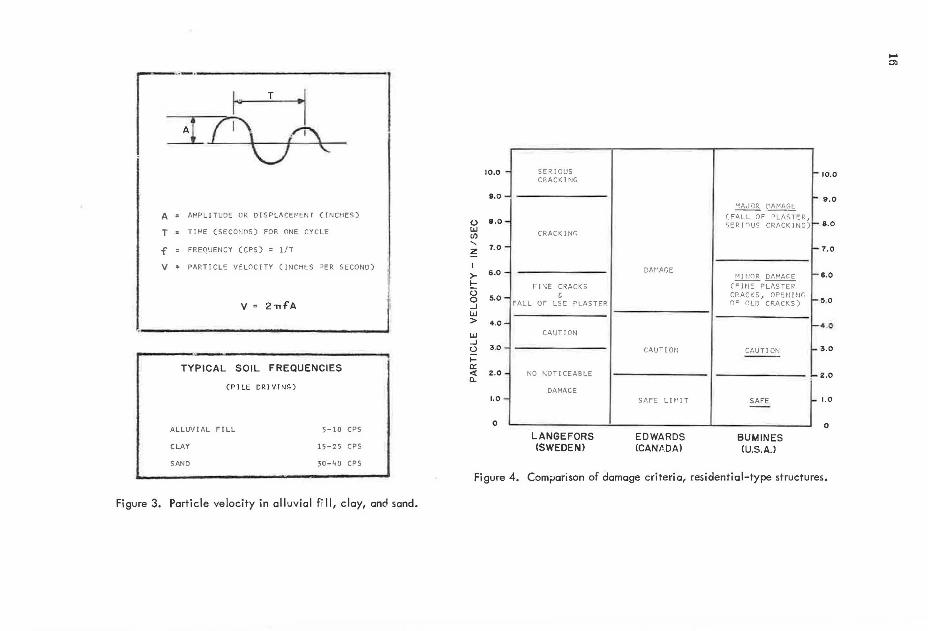
Several investigators in this country and abroad (including the U.S. Bureau of Mines) have found that particle velocities in excess of 4. 0 in. I sec are required to cause plaster cracks in dwellings. Figure 4 shows a comparison of the results of several of the investigations. With appropriate conservatism, the investigators agree that a vibration level of 2. 0 in. /sec (particle velocity) is safe with regard to plaster cracks in residential-type structures.
The effect of ground motion on an engineered structure can be computed by commonly used methods in the earthquake engineering field. The structure is considered a lumped mass-spring dashpot system, and its response to a series of impacts can be calculated. Based on observation and experience, it can be stated that ground motion particle velocities below 4. 0 in. /sec are well within the safe range for engineer structures.
18
.,
.... "' 0:
100
90
~ 80 0 u
u.. 0
J: .... "' z "' "' .... V>
,_ < 0
00 N
u.. 0
70
60
so
40
JO
20
10
-,_
I--
,__
/. 00
Yi
~ ~
fc • 3600 psi
I (28 1ctay)
10 20 JO
CURING TIME - DAYS
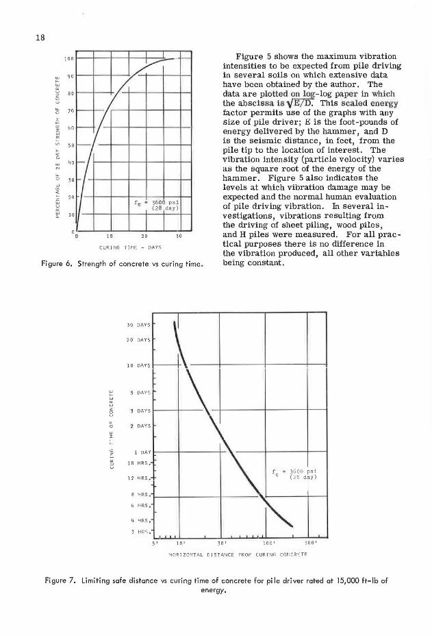
Figure 5 shows the maximum vibration intensities to be expected from pile driving in several soils on which extensive data have been obtained by the author. The data are plotted on log-log paper in which the abscissa is '\/E/ D. This scaled ener gy factor permits use of the graphs with any size of pile driver; E is the foot-pounds of energy delivered by the hammer, and D is the seismic distance, in feet, from the pile tip to the location of interest. The vibration intensity (particle velocity) varies as the square root of the energy of the hammer. Figure 5 also indicates the levels at which vibration damage may be expected and the normal human evaluation of pile driving vibration. In several investigations, vibrations resulting from the driving of sheet piling, wood piles, and H piles were measured. For all practical purposes there is no difference in
Figure 6. Strength of concrete vs curing time . the vibration produced, all other variables being constant.
JO DAYS
20 DAYS
10 DAYS
5 DAYS
J DAYS
LL 0 2 DAYS ., :>:: ;:::
"' 1 DAY ::: 0: 18 HRS. :::> u
12 HRS , f • 3600 p s i
c ( 28 day)
8 HRS .
6 HRS .
4 HRS ,
J HRS ,
5' 10' JO' 100 1 300 1
HORIZONTAL DISTANCE FROM CURINC CONCRETE
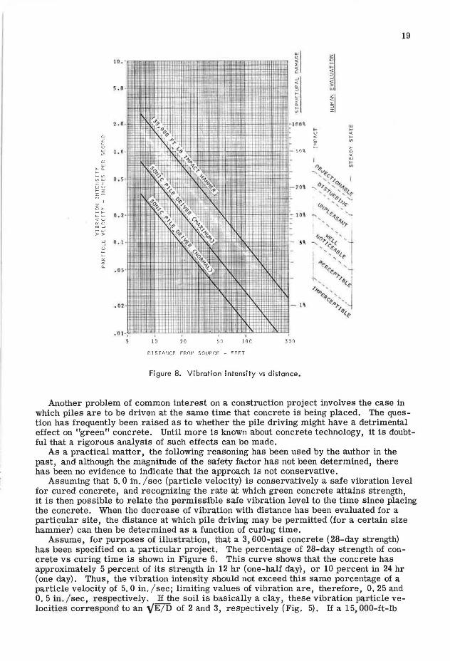
Figure 7. Limiting safe distance vs curing time of concrete for pile driver rated at 15,000 ft-lb of energy.
19
II z 0 ;:: "" :>
...J ...J
"' < c.. > :> "' ..
!I !:; 0. ... v
"' .... "" .... "'
50% >-0
"" w
"' .... w "e "' ~
"' v<l'c-
w ' ,.,, l :r: "'c,,s' ,""-'1e u z , ... '"v~ , (..t
...... o/,.. ...._
>- ~ ' 'G' ~ "c '
0 . 2 · """' e4 ... ._ u ', <l'--q, c ...J ', 'l' w > ..,,o,,..~e< ' ...... w 5, ...J -... ' c- < u ' ~-i ;:: I , - e< "' ' ~ "" "'"" ' ~ •-!> ' "e.., ,.,, '
e< / ~.. ~ 1'.o ' I ~-!> ', ~ "~,, '• ,.,,
el~
DISTANCE FP.OM SOURCE - FEET
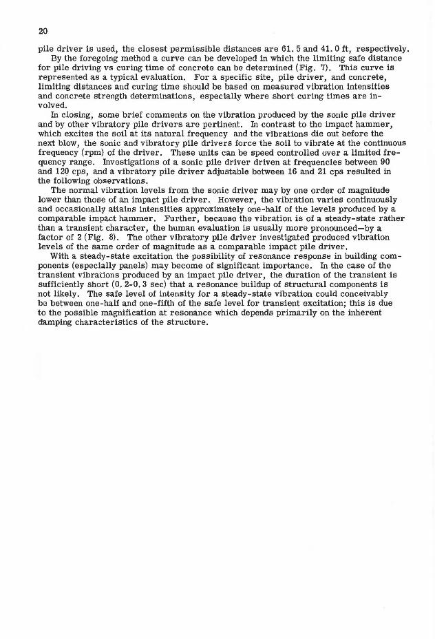
Figure 8. Vibration intensity vs distance.
Another problem of common interest on a construction project involves the case in which piles are to be driven at the same time that concrete is being placed. The question has frequently been raised as to whether the pile driving might have a detrimental effect on "green" concrete. Until more is known about concrete technology, it is doubtful that a rigorous analysis of such effects can be made.
As a practical matter, the following reasoning has been used by the author in the past, and although the magnitude of the safety factor has not been determined, there has been no evidence to indicate that the approach is not conservative.
Assuming that 5. 0 in. /sec (particle velocity) is conservatively a safe vibration level for cured concrete, and recognizing the rate at which green concrete attains strength, it is then possible to relate the permissible safe vibration level to the time since placing the concrete. When the decrease of vibration with distance has been evaluated for a particular site, the distance at which pile driving may be permitted (for a certain size hamnier) can then be determined as a function of curing time.
Assume, for purposes of illustration, that a 3, 600-psi concrete (28-day strength) has been specified on a particular project. The percentage of 28-day strength of concrete vs curing time is shown in Figure 6. This curve shows that the concrete has approximately 5 percent of its strength in 12 hr (one-half day), or 10 percent in 24 hr (one day). Thus, the vibration intensity should not exceed this same percentage of a particle velocity of 5. 0 in. /sec; limiting values of vibration are, therefore, 0. 25 and 0. 5 i.11. / sec, respectively. If the soil is basically a clay, these vibration particle velocities correspond to an '\/E/D of 2 and 3, respectively (Fig. 5). If a 15, 000-ft-lb
20
pile driver is used, the closest permissible distances are 61. 5 and 41. 0 ft, respectively. By the foregoing method a curve can be developed in which the limiting safe distance
for pile driving vs curing time of concrete can be determined (Fig. 7). This curve is represented as a typical evaluation. For a specific site, pile driver, and concrete, limiting distances and curing time should be based on measured vibration intensities and concrete strength determinations, especially where short curing times are involved.
In closing, some brief comments on the vibration produced by the sonic pile driver and by other vibratory pile drivers are pertinent. In contrast to the impact hammer, which excites the soil at its natural frequency and the vibrations die out before the next blow, the sonic and vibratory pile drivers force the soil to vibrate at the continuous frequency (rpm) of the driver. These units can be speed controlled over a limited frequency range. Investigations of a sonic pile driver driven at frequencies between 90 and 120 cps, and a vibratory pile driver adjustable between 16 and 21 cps resulted in the following observations.
The normal vibration levels from the sonic driver may by one order of magnitude lower than those of an impact pile driver. However, the vibration varies continuously and occasionally attains intensities approximately one-half of the levels produced by a comparable impact hammer. Further, because the vibration is of a steady-state rather than a transient character, the human evaluation is usually more pronounced-by a factor of 2 (Fig. 8). The other vibratory pile driver investigated produced vibration levels of the same order of magnitude as a comparable impact pile driver.
With a steady-state excitation the possibility of resonance response in building components (especially panels) may become of significant importance. In the case of the transient vibrations produced by an impact pile driver, the duration of the transient is sufficiently short (O. 2-0. 3 sec) that a resonance buildup of structural components is not likely. The safe level of intensity for a steady-state vibration could conceivably be between one-half and one-fifth of the safe level for transient excitation; this is due to the possible magnification at resonance which depends primarily on the inherent damping characteristics of the structure.