Embed Size (px)
Citation preview
CAPITOL COMPLEX MASTER PLAN
FINDINGS & RECOMMENDATIONS (F & R) NEEDS ASSESSMENT
DALE TOOLEY BUILDING, 690 KIPLING STREET (LAKEWOOD)
NOVEMBER 2014

F I N D I N G S & R E C O M M E N D AT I O N S ( F & R ) N E E D S A S S E S S M E N TD A L E T O O L E Y B U I L D I N G , 6 9 0 K I P L I N G S T R E E T ( L A K E W O O D )
November 2014Page 1
TABLE OF CONTENTS
EXECUTIVE SUMMARY
1.0 OVERVIEW
A. Architecture Overview
B. Structural Overview
C. Civil Overview
D. Mechanical, Electrical, and Plumbing Overview
E. Voice and Data Overview
F. Security Systems Overview
2.0 OVERALL BUILDING ASSESSMENT FINDINGS AND RECOMMENDATIONS
2.1 Architecture
A. Exterior Building Envelope/Site
B. Code Issues
C. General Accessibility Issues
D. Elevators
E. Environmental
F. Planned and On-going Projects
2.2 Structural
A. Exterior Building Envelope
B. Building Interior
C. Fall Protection
D. Planned and On-going Projects
5-6
7-16
7
8
9
10
12
14
17-92
17
33
43
46
46
47
48
51
51
52
TABLE OF CONTENTS
DA L E TO O L E Y BU I L D I N G6 9 0 K I P L I N G S T R E E T ( L A K E WO O D )
November 2014
F I N D I N G S & R E C O M M E N DAT I O N S ( F & R ) N E E D S A S S E S S M E N T

F I N D I N G S & R E C O M M E N D AT I O N S ( F & R ) N E E D S A S S E S S M E N TD A L E T O O L E Y B U I L D I N G , 6 9 0 K I P L I N G S T R E E T ( L A K E W O O D )November 2014Page 2
This page left intentionally blank.
F I N D I N G S & R E C O M M E N D AT I O N S ( F & R ) N E E D S A S S E S S M E N TD A L E T O O L E Y B U I L D I N G , 6 9 0 K I P L I N G S T R E E T ( L A K E W O O D )
November 2014Page 3
TABLE OF CONTENTS
2.3 Civil
A. Exterior Building Envelope/Site
B. Code Issues
C. Planned and On-going Projects
2.4 Mechanical, Electrical, and Plumbing
A. Overview of Existing Systems
B. Code Issues
C. Planned and On-going Projects
2.5 Voice and Data
A. Overview of Existing Systems
B. Code Issues
C. Planned and On-going Projects
2.6 Security Systems
A. Overview of Existing Systems
B. Code Issues
C. Planned and On-going Projects
3.0 FLOOR-BY-FLOOR ASSESSMENT FINDINGS AND RECOMMENDATIONS
A. Code Issues
B. General Accessibility Issues
C. Architectural Finishes and Interior Components
D. Structural
E. Voice and Data
F. Security Systems
4.0 LEVELS OF RENOVATION NEEDED
5.0 COST ESTIMATES
TABLE OF CONTENTS (CONTINUED)
53
57
60
61
74
77
78
83
83
84
90
91
93-112
93
93
93
110
111
111
113-114
115-132

F I N D I N G S & R E C O M M E N D AT I O N S ( F & R ) N E E D S A S S E S S M E N TD A L E T O O L E Y B U I L D I N G , 6 9 0 K I P L I N G S T R E E T ( L A K E W O O D )November 2014Page 4
This page left intentionally blank.
F I N D I N G S & R E C O M M E N D AT I O N S ( F & R ) N E E D S A S S E S S M E N TD A L E T O O L E Y B U I L D I N G , 6 9 0 K I P L I N G S T R E E T ( L A K E W O O D )
November 2014Page 5
EXECUTIVE SUMMARY
The purpose of this report is to provide a Findings & Recommendations (F&R) Needs Assessment of the Dale Tooley Building at 690 Kipling Street in Lakewood, Colorado. The report includes a description and evaluation of the existing conditions, recommendations, and cost estimates for the recommended work from the following focus areas: architecture (RNL), structural (Martin/Martin Consulting Engineers), civil (Martin/Martin Consulting Engineers), mechanical/electrical/plumbing (RMH Group), voice and data (Shen Milsom Wilke), security (Shen Milsom Wilke), and cost estimating (CBRE, Inc.). The project team, led by RNL, reviewed existing building documentation, drawings, and audit reports provided by the Owner, and conducted a site visit to identify and document the observable existing conditions of the building and its code and life safety issues.
In general the building is in fair condition. A fair condition rating refers to the fact that the Dale Tooley Building is usable but in serious need of repairs to address life safety and loss of use/reliability issues.
Although all recommendations presented in this report should be considered for implementation, the following are the top five priorities due to their impact on life safety (LS), loss of use/reliability (LOU), finishes (F), and overall energy efficiency:
1. Replace fire alarm. This recommendation encompasses life safety issues and is due to fire protection code issues and the age of the system.
High Level Cost Estimate: $239,328
2. Modernize elevators. This recommendation encompasses life safety issues and is due to the age of the elevator systems.
High Level Cost Estimate: $204,275
3. Upgrade the data center UPS. This recommendation encompasses loss of use/reliability issues and is due to the need for a UPS system that will provide adequate capacity, reliability, and redundancy.
High Level Cost Estimate: $224,328
4. Add electrical capacity. This recommendation encompasses loss of use/reliability issues and is due to the need for increased capacity.
High Level Cost Estimate: $1,018,827
EXECUTIVE SUMMARY
F I N D I N G S & R E C O M M E N D AT I O N S ( F & R ) N E E D S A S S E S S M E N TD A L E T O O L E Y B U I L D I N G , 6 9 0 K I P L I N G S T R E E T ( L A K E W O O D )November 2014Page 6
5. Replace windows. This recommendation encompasses loss of use/reliability issues and is due to the age and condition of the windows.
High Level Cost Estimate: $856,823
If all recommendations in this report are implemented as a single project, including the top 5 priorities, the high level cost estimate is:
$8,857,325
If all recommendations in this report are implemented system by system as multiple projects, including the top 5 priorities (systems), the high level cost estimate is:
$8,949,125
F I N D I N G S & R E C O M M E N D AT I O N S ( F & R ) N E E D S A S S E S S M E N TD A L E T O O L E Y B U I L D I N G , 6 9 0 K I P L I N G S T R E E T ( L A K E W O O D )
November 2014Page 7
1.0 OVERVIEW
1.0-A ARCHITECTURE OVERVIEW
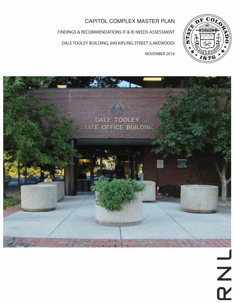
The Dale Tooley State Office Building was constructed in 1985, according to documentation provided by the Owner, and is located in Lakewood, Colorado on the northeast corner of 6th Avenue and Kipling Street. The building currently serves as government office space for the Colorado Department of Public Safety and houses servers for the Office of Information Technology. The Dale Tooley Building, consisting of a concrete and metal frame clad in brick, is a four-story building and grosses 67,035 square feet of space.
The architectural assessment of the Dale Tooley Building at 690 Kipling Street included reviews of the existing building documentation, drawings, and audit reports provided by the Owner, and a site visit to survey and document the existing conditions of the building and its code and life safety issues. During the site survey on October 1, 2013, building maintenance personnel provided building history and information on the layout, finishes, maintenance routines, systems, and the dates of repairs and upgrades. In general, the building is in fair condition. There are issues related to interior and exterior finish materials, building systems, code compliance, accessibility, and other items that require attention in the near term. One of the main concerns is related to the age and condition of the roof. Other concerns include code issues with the exits and the age and condition of the windows. These concerns encompass life safety, loss of use/reliability, and overall energy efficiency issues. These findings, along with recommendations for repairs, are detailed in the body of this report.
1.0 OVERVIEW
F I N D I N G S & R E C O M M E N D AT I O N S ( F & R ) N E E D S A S S E S S M E N TD A L E T O O L E Y B U I L D I N G , 6 9 0 K I P L I N G S T R E E T ( L A K E W O O D )November 2014Page 8
1.0-B STRUCTURAL OVERVIEW
Martin/Martin conducted a building condition assessment on October 1, 2013 of the Dale Tooley State Office Building located at 690 Kipling Street in Lakewood, Colorado. The purpose of our condition assessment was to identify structural defects, damage and deterioration.
The Dale Tooley State Office building was constructed in 1984. The structural framing consists of slab on metal deck supported by steel joists, steel girders and steel columns. The foundation system is unknown and construction drawings were not available.
The structural framing that was readily observable is in good condition. The loading dock area at the southeast corner had significant corrosion and deterioration.
RF antennas were observed on the roof with no warning signs. Proper signage should be provided to avoid exposing people to harmful radiation.
Parapets along the roof edge were found to be of inadequate height. A fall protection system should be provided for access near exposed edges to meet current safety codes.
F I N D I N G S & R E C O M M E N D AT I O N S ( F & R ) N E E D S A S S E S S M E N TD A L E T O O L E Y B U I L D I N G , 6 9 0 K I P L I N G S T R E E T ( L A K E W O O D )
November 2014Page 9
1.O-C CIVIL OVERVIEW
The Dale Tooley State Office Building site is approximately 2 acres and is located at 690 Kipling Street in Lakewood, Colorado. The existing site consists of the building, site landscaping, parking lot and street right-of-way including sidewalk and landscaping. The main building entrance is accessed from the parking lot on the west side. The condition of the site surrounding the building is consistent with an estimated age of 30+ years.
The site exterior is generally in fair condition. There are numerous locations around the building with broken and cracked concrete in need of repair or replacement. Broken surfaces in walking paths is a tripping hazard and a high safety concern. The main concern regarding the site is the drainage away from the building. The landscaped areas are flat and appear to slope back towards the building at some locations. Landscape should be modified to provide positive drainage away from the building to prevent saturating the foundation and causing loss of use. While the existing building functions in its current state, improvements can be made to improve drainage, comply with regulations and enhance aesthetics.
1.0 OVERVIEW
F I N D I N G S & R E C O M M E N D AT I O N S ( F & R ) N E E D S A S S E S S M E N TD A L E T O O L E Y B U I L D I N G , 6 9 0 K I P L I N G S T R E E T ( L A K E W O O D )November 2014Page 10
1.0-D MECHANICAL, ELECTRICAL, AND PLUMBING OVERVIEW
The 690 Kipling St. building is a four story building built around 1984. The building houses laboratories on the fourth floor and offices on the other three floors and the OIT data center on the first floor. The electrical and mechanical assessment of the building included review of the existing building documentation, drawings, and audit reports provided by the Owner. A site survey for the facility was performed to observe the existing electrical and mechanical equipment installation and assess code and building energy efficiency issues. During the site survey, information about the building history and on the electrical and mechanical systems conditions, maintenance routines, and installation dates was noted.
The main concerns regarding the Dale Tooley Building are related to the age of the fire alarm system, the age of the data center UPS, and the need for additional electrical capacity. The fire alarm system needs to be replaced with the new Notifer system used in the other government buildings. Upgrade the UPS system to provide more capacity, reliability, and redundancy. Upgrade the normal power electrical system to provide at least 50% more capacity for future growth.
The fire alarm system is a life safety system that protects life and property. It is critical to have a full detection system that is working properly.
The fire pump layout and clearances do not meet current code requirements. Provide a larger room and reconfigure the piping within the pump room. The sprinkler piping within the building is old and must be corroded from inside. The piping is susceptible to leaks and should be replaced to improve life safety in the building.
Energy Conservation
To conserve energy in this building a lighting control system that provides automatic daylight dimming and occupancy sensor shutoff will provide energy savings. Also, following the most up-to-date energy codes regarding how much light is used (watts per square feet) will reduce the number of fixtures required for each space. Supplemental task lighting can be used on the desk or in the cubicles to ensure occupants are able to perform their work effectively.
Since the tenants in the building can be different, sub-metering on each panelboard will help keep track of power usage. This will help notify building users of excess use of power so adjustments can be made to their usage.
F I N D I N G S & R E C O M M E N D AT I O N S ( F & R ) N E E D S A S S E S S M E N TD A L E T O O L E Y B U I L D I N G , 6 9 0 K I P L I N G S T R E E T ( L A K E W O O D )
November 2014Page 11
1.0 OVERVIEW
Providing automatic occupancy sensor shutoff power strips for desk equipment that does not need to be on constantly, when a person is away from their desk, will help reduce energy usage.
The HVAC unit serving the lab is at the end of its useful life and should be replaced with new high efficiency unit. This will improve the conditions in the lab and also save cooling energy cost. The airflows in the labs will need to be balanced by providing lab hood controls and new VAV boxes. This will allow maintaining the pressure difference between various rooms. The air distribution in the office spaces is via old Carrier VAV units. These units are not efficient and should be replaced with new VAVs with Direct Digital Controls (DDC). These changes in the labs and office areas will improve the space comfort conditions and also save energy. Providing new DDC controls will enable to use energy saving features which will save heating and cooling energy costs.
The possibility of replacing the electric heat with hydronic hot water heat should be investigated. This will improve the comfort conditions and also save heating energy costs.
F I N D I N G S & R E C O M M E N D AT I O N S ( F & R ) N E E D S A S S E S S M E N TD A L E T O O L E Y B U I L D I N G , 6 9 0 K I P L I N G S T R E E T ( L A K E W O O D )November 2014Page 12
1.0-E VOICE AND DATA OVERVIEW
The Voice and Data IT/Telecommunications Infrastructure assessment and findings report provides recommendations for the design and construction of the IT/Telecommunications Infrastructure required to support Voice/Data and other technology systems within the Dale Tooley building. It has been found that much of the building’s existing IT/Telecommunications infrastructure is not compliant with current industry standards and best practice installation methods. As well, the current infrastructure is such that it may not properly support many newer technology IP devices which are now considered to be standard in the industry such as VoIP phones and PoE type security cameras. Existing Cat5e cabling has bandwidth limitations as compared to that of more robust, industry standard Cat6/6A cable plant specifications. The complete IT systems infrastructure not only includes the cabling, but the cabling pathways and the spaces (or rooms) that support the network cabling. Technology spaces requiring to be properly outfitted in the building include the Main Distribution Facility (MDF) room, and distributed IDF rooms (minimum of one per floor). Backbone infrastructure shall include proper cabling pathways between MDF/IDF rooms, in order to support installation of both fiber and copper backbone cabling. Singlemode and laser optimized multimode fiber optic cables, along with Category 3 copper backbone cables should be installed from the MDF room to each IDF room to support the technology systems. Category 6 UTP cable shall be installed from the telecom outlets and IP field devices to termination hardware in the IDF rooms using the conduit and cable tray horizontal pathways. A proper grounding and bonding system must be provisioned for, and will provide a uniform ground within the telecommunications rooms, to ensure safe and reliable operation of the communications and low-voltage equipment and systems. These recommendations may be used for IT/Telecom Infrastructure program development, space planning, and budgeting of these systems at a conceptual design level. Industry standard and best practice design methods must be applied, including BICSI and TIA/EIA design and construction guidelines. For renovation projects, any applicable State Office of Information Technology (OIT) design criteria documents should be should be followed.
The following list prioritizes voice/data infrastructure upgrades required:
1. Necessary: Retrofit facility with proper MDF/IDF room distribution, which meets industry standard for telecommunication structured cabling system.
2. Necessary: Replace horizontal copper station cabling with Cat 6 network cabling.
F I N D I N G S & R E C O M M E N D AT I O N S ( F & R ) N E E D S A S S E S S M E N TD A L E T O O L E Y B U I L D I N G , 6 9 0 K I P L I N G S T R E E T ( L A K E W O O D )
November 2014Page 13
3. Necessary: Replace vertical and network backbone cabling with appropriate copper and fiber optic cabling.
4. Necessary: Provide voice/data infrastructure to support wireless access points (WAPs), for wireless network coverage throughout facility.
1.0 OVERVIEW
F I N D I N G S & R E C O M M E N D AT I O N S ( F & R ) N E E D S A S S E S S M E N TD A L E T O O L E Y B U I L D I N G , 6 9 0 K I P L I N G S T R E E T ( L A K E W O O D )November 2014Page 14
1.0-F SECURITY SYSTEMS OVERVIEW
The security systems design guidelines outline electronic security systems infrastructure which will enhance security operations and provide a safe and secure environment for persons and assets within the Dale Tooley Building. The security systems should be planned and designed to allow the security personnel the operational flexibility to provide various levels of security based on the threat level at a given time. Security systems should be designed such that they may be monitored remotely from centralized security monitoring locations. Best practice security design methodology should be applied, including crime prevention through environmental design (CPTED), layered security, integrated design, and concentric circles of protection. Additionally it is recommended that the following document be used a guideline for developing specific security design criteria for renovations: ASIS Facilities Physical Security Measures, IESNA G-1-03 Guideline for Security Lighting, Unified Facilities Criteria UFC 4-010-01.
For renovation projects, applicable State construction standards and design guidelines must be followed. Electronic security systems to be considered for implementation or upgrade include access control, intrusion detection, duress alarm, intercom, video surveillance, and emergency call system. The access control system (ACS) will be an expansion of the existing campus wide system currently installed throughout other State buildings. The ACS shall also serve as the primary security management system for monitoring intrusion alarms. The video surveillance system (VSS) should be comprised of IP digital cameras integrated with the existing VSS. The State’s existing wireless duress alarm system infrastructure should be expanded where needed to support new locations of wireless duress buttons.
Existing security systems in State facilities are generally controlled and monitored centrally from Colorado State Patrol’s Central Command Center (CCC), located in Denver CO.
Within the building, new head-end security control equipment is to be located in IDF or technology rooms, as coordinated with State IT technical staff. Equipment may include ACS control panels, power supplies, duress alarm panels, network video recorders, and UPS units.
All critical electronic security equipment should be backed-up with emergency power circuits or UPS units. State security personnel and other authorized staff may remotely monitor access control events, system alarms, and security video through network connected client workstations.
F I N D I N G S & R E C O M M E N D AT I O N S ( F & R ) N E E D S A S S E S S M E N TD A L E T O O L E Y B U I L D I N G , 6 9 0 K I P L I N G S T R E E T ( L A K E W O O D )
November 2014Page 15
For the Dale Tooley Building renovation work, requirements for security device additions/upgrades and specific security system functionality are to be coordinated with State security personnel during design and construction phases.
The following list prioritizes security system upgrades required:
1. Necessary: Replace/Repair existing Hirsch Access Control card readers.
2. Necessary: Replace analog security cameras with IP PoE minimum 1.2MP cameras.
3. Necessary: Replace existing coaxial CCTV cabling with CAT 6 network cabling, required to support item above.
4. Necessary: Verify functionality of access control devices and perimeter door alarms, replace if defective. Provide door sensor alarm on all perimeter doors.
5. Necessary: Verify functionality of wireless duress alarms. Provide duress alarms for all public interface counters and cash handling areas.
6. Recommended: Install IP security camera within main entrance/lobby.
7. Recommended: Install intercom station at facility main entrance door exterior. Must be intercom-over-IP (IoIP) based PoE intercom stations. Install IP camera to view intercom.
Consideration should be given in regards to the Installation and mounting details for any security related renovations. Due to the uniqueness of the buildings under consideration, design plans must be cognizant of maintaining the historical attributes of the buildings.
1.0 OVERVIEW

F I N D I N G S & R E C O M M E N D AT I O N S ( F & R ) N E E D S A S S E S S M E N TD A L E T O O L E Y B U I L D I N G , 6 9 0 K I P L I N G S T R E E T ( L A K E W O O D )November 2014Page 16
This page left intentionally blank.
F I N D I N G S & R E C O M M E N D AT I O N S ( F & R ) N E E D S A S S E S S M E N TD A L E T O O L E Y B U I L D I N G , 6 9 0 K I P L I N G S T R E E T ( L A K E W O O D )
November 2014Page 17
2.0 OVERALL BUILDING ASSESSMENT FINDINGS AND RECOMENDATIONS
2.1 ARCHITECTURE
2.1-A EXTERIOR BUILDING ENVELOPE/SITE
General
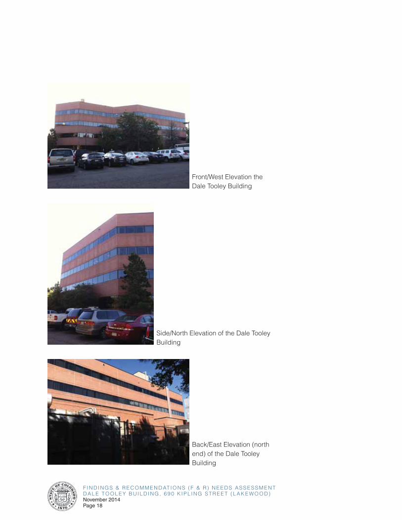
The Dale Tooley Building is a four-story tall building, supported by a
concrete and metal structural frame. The facade is clad in brick and has
continuous ribbon windows along each story. The main building entrance is
on the west side and is set back from the front edge of the building, creating
a two-story covered entryway. The main entrance is paved in concrete, with
brick framing the edges, and continues to a concrete sidewalk extending
around the sides of the building and serving the parking areas. There is a
second entrance for employees located on the north side of the building.
The roof contains a one-story elevator penthouse set back from the
elevations of the building. There is a lower roof above a two-story section
of the building along the length of the east elevation at the rear. The low
parapet is covered with a waterproof membrane on the inside face and
capped with a metal coping.
It was reported that there is currently no weather barrier in the exterior
walls and that water periodically leaks into the building during wet weather
conditions. It was also reported that the walls are not insulated.
The building envelope is in fair condition overall. Various elements are
showing the effects of deferred maintenance, others are simply damaged or
worn out. Some soiling of the brick has occurred under the windows around
the building’s exterior.
2.0 OVERALL BUILDING ASSESSMENT FINDINGS & RECOMMENDATIONS
F I N D I N G S & R E C O M M E N D AT I O N S ( F & R ) N E E D S A S S E S S M E N TD A L E T O O L E Y B U I L D I N G , 6 9 0 K I P L I N G S T R E E T ( L A K E W O O D )November 2014Page 18
Front/West Elevation the Dale Tooley Building
Side/North Elevation of the Dale Tooley Building
Back/East Elevation (north end) of the Dale Tooley Building
F I N D I N G S & R E C O M M E N D AT I O N S ( F & R ) N E E D S A S S E S S M E N TD A L E T O O L E Y B U I L D I N G , 6 9 0 K I P L I N G S T R E E T ( L A K E W O O D )
November 2014Page 19
2.0 OVERALL BUILDING ASSESSMENT FINDINGS & RECOMMENDATIONS
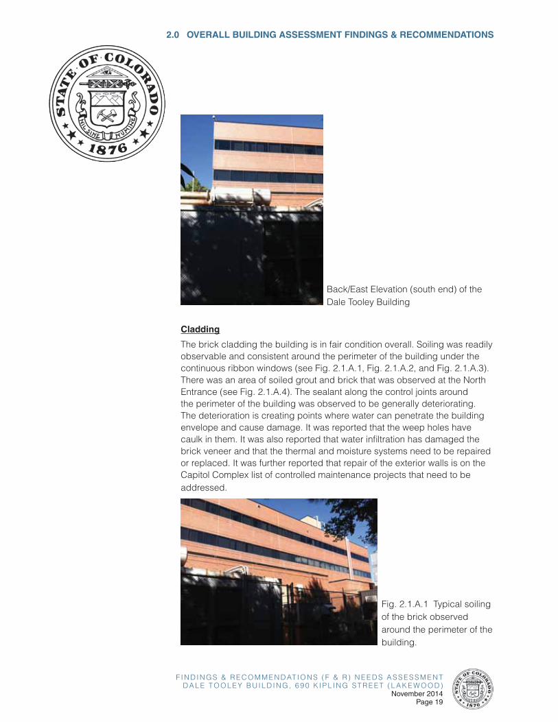
Back/East Elevation (south end) of the Dale Tooley Building
Cladding
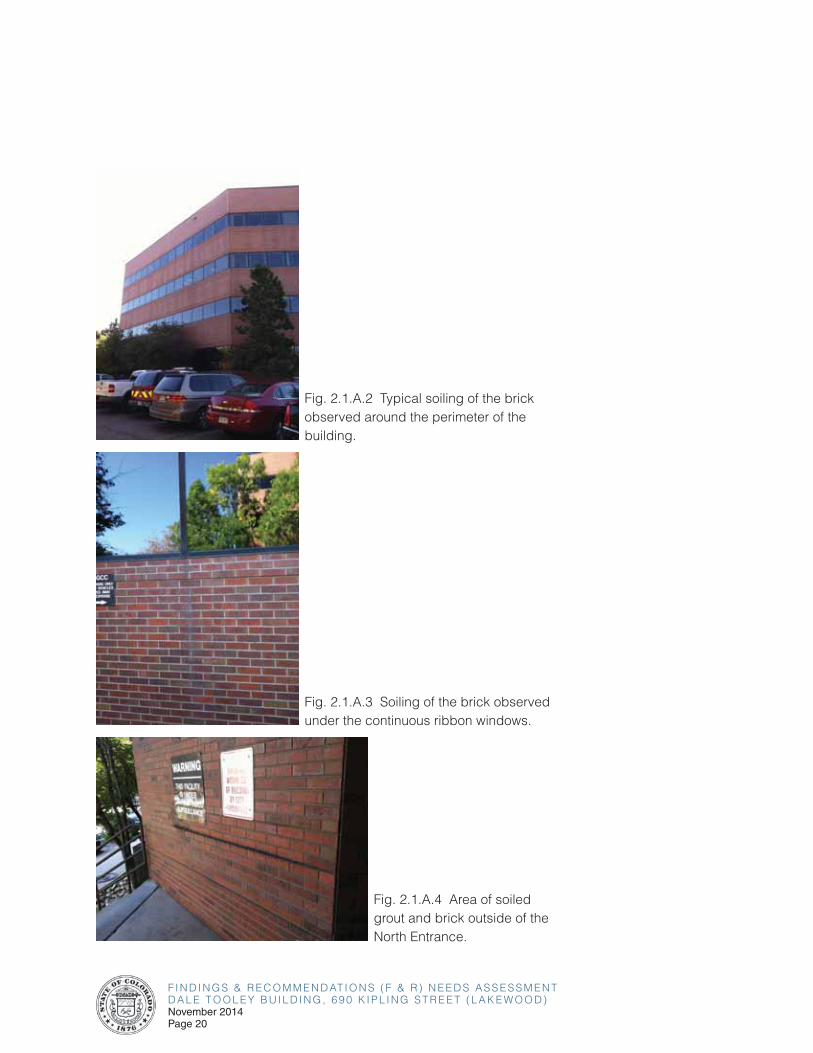
The brick cladding the building is in fair condition overall. Soiling was readily observable and consistent around the perimeter of the building under the continuous ribbon windows (see Fig. 2.1.A.1, Fig. 2.1.A.2, and Fig. 2.1.A.3). There was an area of soiled grout and brick that was observed at the North Entrance (see Fig. 2.1.A.4). The sealant along the control joints around the perimeter of the building was observed to be generally deteriorating. The deterioration is creating points where water can penetrate the building envelope and cause damage. It was reported that the weep holes have caulk in them. It was also reported that water infiltration has damaged the brick veneer and that the thermal and moisture systems need to be repaired or replaced. It was further reported that repair of the exterior walls is on the Capitol Complex list of controlled maintenance projects that need to be addressed.
Fig. 2.1.A.1 Typical soiling of the brick observed around the perimeter of the building.
F I N D I N G S & R E C O M M E N D AT I O N S ( F & R ) N E E D S A S S E S S M E N TD A L E T O O L E Y B U I L D I N G , 6 9 0 K I P L I N G S T R E E T ( L A K E W O O D )November 2014Page 20
Fig. 2.1.A.2 Typical soiling of the brick observed around the perimeter of the building.
Fig. 2.1.A.3 Soiling of the brick observed under the continuous ribbon windows.
Fig. 2.1.A.4 Area of soiled grout and brick outside of the North Entrance.
F I N D I N G S & R E C O M M E N D AT I O N S ( F & R ) N E E D S A S S E S S M E N TD A L E T O O L E Y B U I L D I N G , 6 9 0 K I P L I N G S T R E E T ( L A K E W O O D )
November 2014Page 21
2.0 OVERALL BUILDING ASSESSMENT FINDINGS & RECOMMENDATIONS
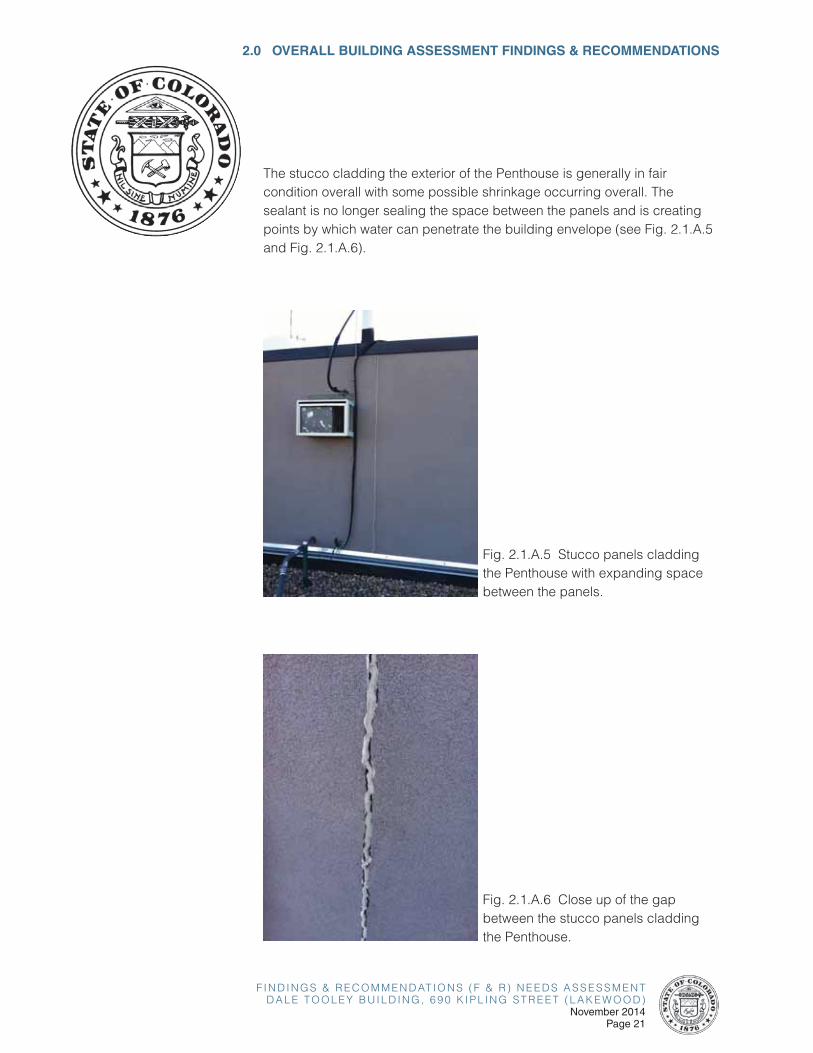
The stucco cladding the exterior of the Penthouse is generally in fair condition overall with some possible shrinkage occurring overall. The sealant is no longer sealing the space between the panels and is creating points by which water can penetrate the building envelope (see Fig. 2.1.A.5 and Fig. 2.1.A.6).
Fig. 2.1.A.5 Stucco panels cladding the Penthouse with expanding space between the panels.
Fig. 2.1.A.6 Close up of the gap between the stucco panels cladding the Penthouse.
F I N D I N G S & R E C O M M E N D AT I O N S ( F & R ) N E E D S A S S E S S M E N TD A L E T O O L E Y B U I L D I N G , 6 9 0 K I P L I N G S T R E E T ( L A K E W O O D )November 2014Page 22
Recommendations:
• Clean soiled/stained brick veneer around the building exterior.
• Remove existing sealant in control joints around the building exterior, including at the Penthouse, and replace with new sealant. Sealant, backup materials, and preformed joint fillers should be nonstaining.
• Repair or replace damaged brick veneer around the exterior of the building.
• Remove any material, including but not limited to caulk, from the weep holes around the exterior of the building. Repair or replace damaged weep holes as necessary.
• Insulate the exterior walls of the building as necessary to provide temperature control and energy savings.
• Further forensic investigation, such as a smoke test, is required prior to any recommendations regarding the potential installation of a weather barrier. Investigate and determine the cause of water infiltration around the exterior walls and repair as necessary.
Glazing Systems and Doors
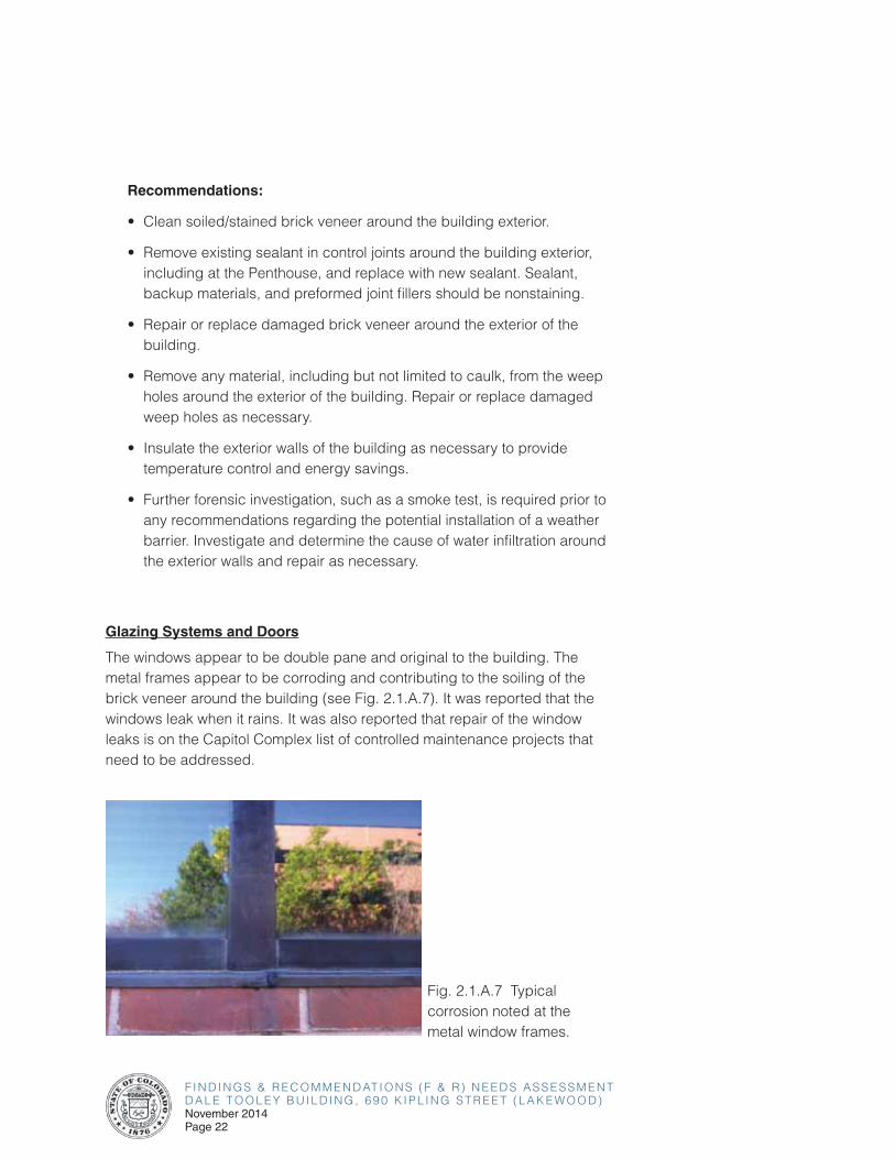
The windows appear to be double pane and original to the building. The metal frames appear to be corroding and contributing to the soiling of the brick veneer around the building (see Fig. 2.1.A.7). It was reported that the windows leak when it rains. It was also reported that repair of the window leaks is on the Capitol Complex list of controlled maintenance projects that need to be addressed.
Fig. 2.1.A.7 Typical corrosion noted at the metal window frames.

F I N D I N G S & R E C O M M E N D AT I O N S ( F & R ) N E E D S A S S E S S M E N TD A L E T O O L E Y B U I L D I N G , 6 9 0 K I P L I N G S T R E E T ( L A K E W O O D )
November 2014Page 23
2.0 OVERALL BUILDING ASSESSMENT FINDINGS & RECOMMENDATIONS
The single sets of glazed entrance doors at the West Entrance and the North Entrance appear to be in fair condition and original to the building. Minor deterioration of the weatherstripping was noted, allowing air leakage from the building. The emergency exit door, from roughly the middle of the east side of the building, appears to have been half-coated with some form of sealant or paint (see Fig. 2.1.A.8). The Penthouse door has minor areas of corrosion and paint which is wearing thin in several spots which could lead to further, and much more widespread, corrosion (see Fig. 2.1.A.9).
Fig. 2.1.A.8 Emergency exit doors near the middle of the east side of the building.
Fig. 2.1.A.9 Penthouse door with minor corrosion and paint wearing thin overall.
F I N D I N G S & R E C O M M E N D AT I O N S ( F & R ) N E E D S A S S E S S M E N TD A L E T O O L E Y B U I L D I N G , 6 9 0 K I P L I N G S T R E E T ( L A K E W O O D )November 2014Page 24
Recommendations:
• Replace existing windows with new energy efficient windows and
frames.
• Repair or replace the weatherstripping between all exterior doors and
their frames to prevent air leakage.
• Repair or replace the corroding door and frame at the Penthouse.
Roof
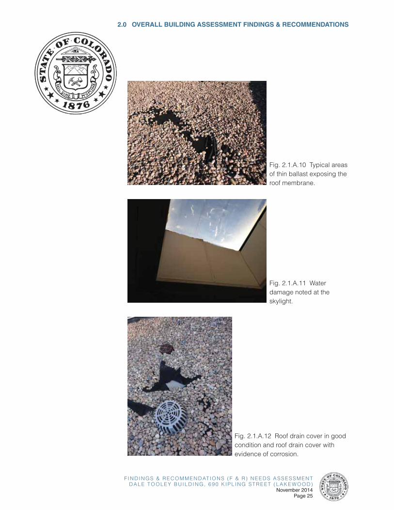
It was reported that the roof of the Dale Tooley Building is around ten years
old. The roof is ballasted and is thin or missing in spots, exposing the roof
membrane (see Fig. 2.1.A.10). It was further reported that the roof has
numerous issues with leaking, and that the leaking was especially apparent
during the recent rainy weather this past September (2013). Water damage
was readily observed to the ceiling of the Fourth Floor and to the skylight
(see Fig. 2.1.A.11). It was reported that the skylight needs to be replaced.
Some of the roof drain covers are in good condition and some are showing
evidence of corrosion (see Fig. 2.1.A.12, Fig. 2.1.A.13, and Fig. 2.1.A.14).
The sealant is deteriorating along the seams of the roofing membrane
and areas of the roofing membrane covering the inside face of the roof
parapet are bubbling (see Fig. 2.1.A.15, Fig. 2.1.A.16, and Fig. 2.1.A.17).
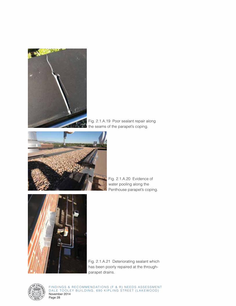
The coping along the parapet has areas of deteriorating sealant and areas
where the sealant has been repaired poorly along the seams of the coping
(see Fig. 2.1.A.18 and Fig. 2.1.A.19). The coping of the Penthouse parapet
appears to be flat and there is evidence of pooling water (see Fig. 2.1.A.20).
The sealant is deteriorating and has been poorly repaired around the
through-wall parapet drains (see Fig. 2.1.A.21). It was reported that the roof
needs to be replaced and that more stepping stones (concrete pavers) are
needed.
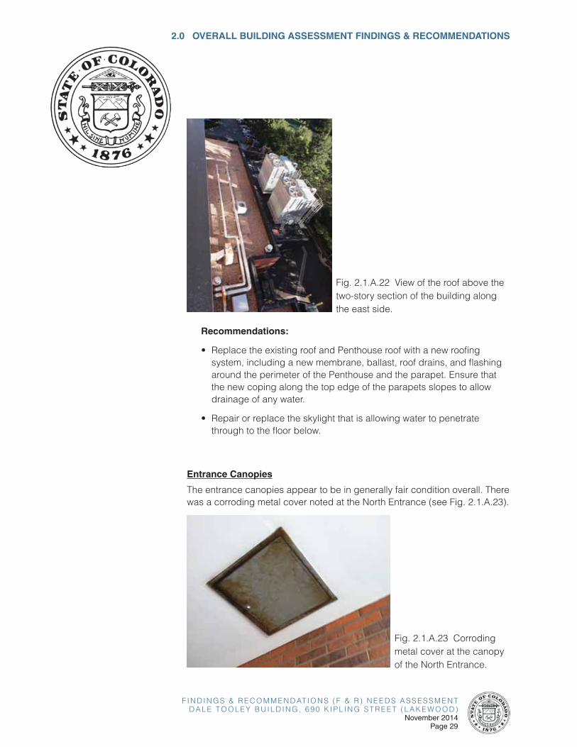
There is a roof covering the two-story portion of the building along the east
elevation which appeared to be in fair condition as observed from the main
roof above (see Fig. 2.1.A.22).
F I N D I N G S & R E C O M M E N D AT I O N S ( F & R ) N E E D S A S S E S S M E N TD A L E T O O L E Y B U I L D I N G , 6 9 0 K I P L I N G S T R E E T ( L A K E W O O D )
November 2014Page 25
2.0 OVERALL BUILDING ASSESSMENT FINDINGS & RECOMMENDATIONS
Fig. 2.1.A.10 Typical areas of thin ballast exposing the roof membrane.
Fig. 2.1.A.11 Water damage noted at the skylight.
Fig. 2.1.A.12 Roof drain cover in good condition and roof drain cover with evidence of corrosion.

F I N D I N G S & R E C O M M E N D AT I O N S ( F & R ) N E E D S A S S E S S M E N TD A L E T O O L E Y B U I L D I N G , 6 9 0 K I P L I N G S T R E E T ( L A K E W O O D )November 2014Page 26
Fig. 2.1.A.13 Corroding roof drain cover.
Fig. 2.1.A.14 Corroding roof exhaust vent.
Fig. 2.1.A.15 Deteriorating sealant along the seams of the roofing membrane covering the inside face of the parapet.

F I N D I N G S & R E C O M M E N D AT I O N S ( F & R ) N E E D S A S S E S S M E N TD A L E T O O L E Y B U I L D I N G , 6 9 0 K I P L I N G S T R E E T ( L A K E W O O D )
November 2014Page 27
2.0 OVERALL BUILDING ASSESSMENT FINDINGS & RECOMMENDATIONS
Fig. 2.1.A.16 Deteriorating sealant along the seams of the roofing membrane covering the inside face of the parapet.
Fig. 2.1.A.17 Deteriorating sealant along the seams of the roofing membrane and bubbling of the roofing membrane covering the inside face of the parapet.
Fig. 2.1.A.18 Poor sealant repair along the seams of the parapet’s coping and evidence of pooling water.
F I N D I N G S & R E C O M M E N D AT I O N S ( F & R ) N E E D S A S S E S S M E N TD A L E T O O L E Y B U I L D I N G , 6 9 0 K I P L I N G S T R E E T ( L A K E W O O D )November 2014Page 28
Fig. 2.1.A.19 Poor sealant repair along the seams of the parapet’s coping.
Fig. 2.1.A.20 Evidence of water pooling along the Penthouse parapet’s coping.
Fig. 2.1.A.21 Deteriorating sealant which has been poorly repaired at the through-parapet drains.
F I N D I N G S & R E C O M M E N D AT I O N S ( F & R ) N E E D S A S S E S S M E N TD A L E T O O L E Y B U I L D I N G , 6 9 0 K I P L I N G S T R E E T ( L A K E W O O D )
November 2014Page 29
2.0 OVERALL BUILDING ASSESSMENT FINDINGS & RECOMMENDATIONS
Fig. 2.1.A.22 View of the roof above the two-story section of the building along the east side.
Recommendations:
• Replace the existing roof and Penthouse roof with a new roofing system, including a new membrane, ballast, roof drains, and flashing around the perimeter of the Penthouse and the parapet. Ensure that the new coping along the top edge of the parapets slopes to allow drainage of any water.
• Repair or replace the skylight that is allowing water to penetrate through to the floor below.
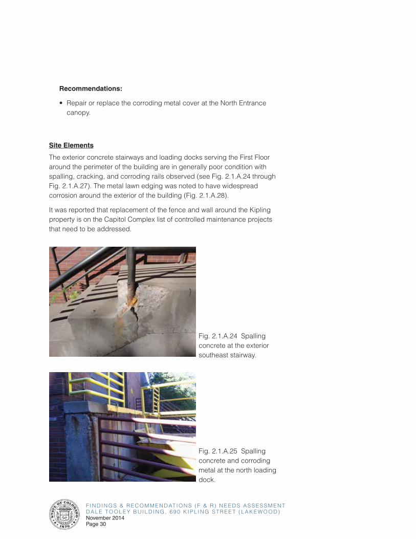
Entrance Canopies
The entrance canopies appear to be in generally fair condition overall. There was a corroding metal cover noted at the North Entrance (see Fig. 2.1.A.23).
Fig. 2.1.A.23 Corroding metal cover at the canopy of the North Entrance.
F I N D I N G S & R E C O M M E N D AT I O N S ( F & R ) N E E D S A S S E S S M E N TD A L E T O O L E Y B U I L D I N G , 6 9 0 K I P L I N G S T R E E T ( L A K E W O O D )November 2014Page 30
Recommendations:
• Repair or replace the corroding metal cover at the North Entrance canopy.
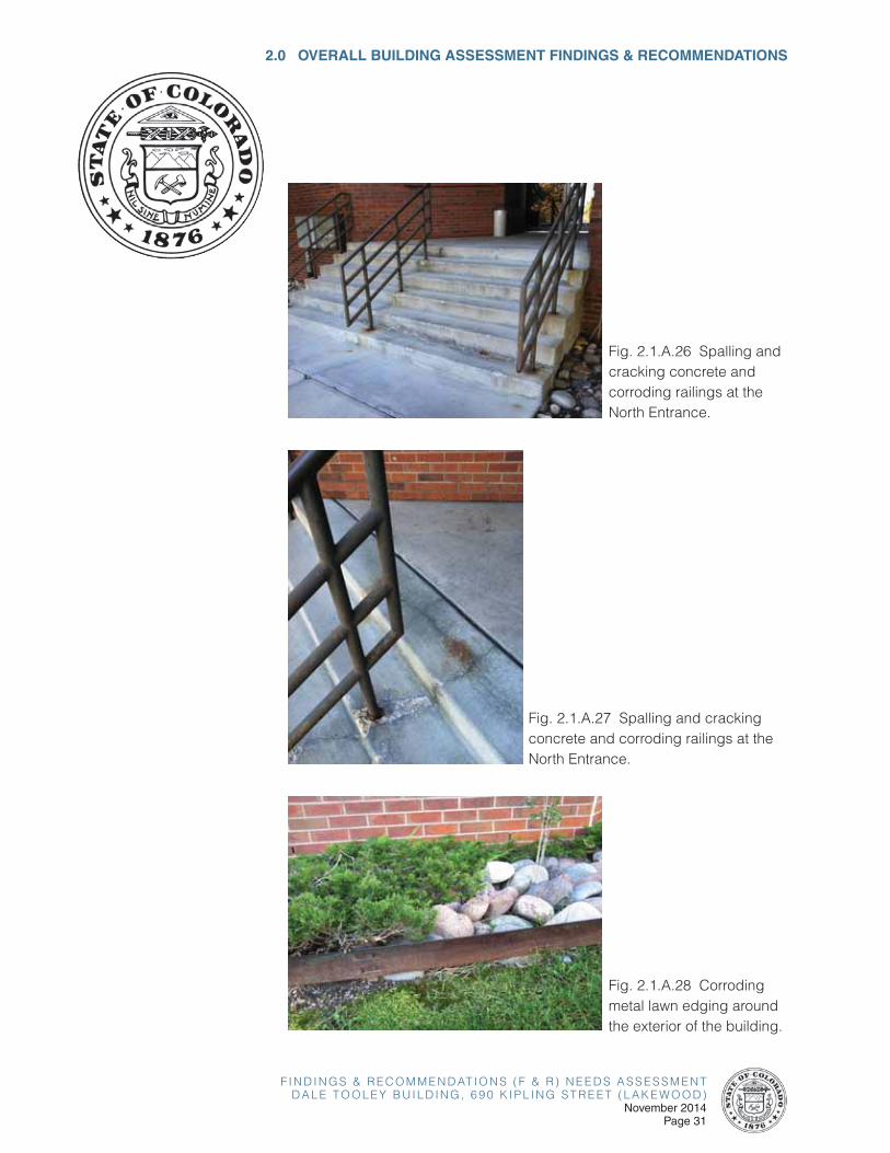
Site Elements
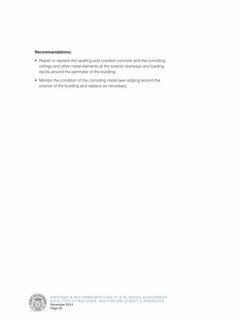
The exterior concrete stairways and loading docks serving the First Floor around the perimeter of the building are in generally poor condition with spalling, cracking, and corroding rails observed (see Fig. 2.1.A.24 through Fig. 2.1.A.27). The metal lawn edging was noted to have widespread corrosion around the exterior of the building (Fig. 2.1.A.28).
It was reported that replacement of the fence and wall around the Kipling property is on the Capitol Complex list of controlled maintenance projects that need to be addressed.
Fig. 2.1.A.24 Spalling concrete at the exterior southeast stairway.
Fig. 2.1.A.25 Spalling concrete and corroding metal at the north loading dock.
F I N D I N G S & R E C O M M E N D AT I O N S ( F & R ) N E E D S A S S E S S M E N TD A L E T O O L E Y B U I L D I N G , 6 9 0 K I P L I N G S T R E E T ( L A K E W O O D )
November 2014Page 31
2.0 OVERALL BUILDING ASSESSMENT FINDINGS & RECOMMENDATIONS
Fig. 2.1.A.26 Spalling and cracking concrete and corroding railings at the North Entrance.
Fig. 2.1.A.27 Spalling and cracking concrete and corroding railings at the North Entrance.
Fig. 2.1.A.28 Corroding metal lawn edging around the exterior of the building.
F I N D I N G S & R E C O M M E N D AT I O N S ( F & R ) N E E D S A S S E S S M E N TD A L E T O O L E Y B U I L D I N G , 6 9 0 K I P L I N G S T R E E T ( L A K E W O O D )November 2014Page 32
Recommendations:
• Repair or replace the spalling and cracked concrete and the corroding railings and other metal elements at the exterior stairways and loading docks around the perimeter of the building.
• Monitor the condition of the corroding metal lawn edging around the exterior of the building and replace as necessary.
F I N D I N G S & R E C O M M E N D AT I O N S ( F & R ) N E E D S A S S E S S M E N TD A L E T O O L E Y B U I L D I N G , 6 9 0 K I P L I N G S T R E E T ( L A K E W O O D )
November 2014Page 33
2.0 OVERALL BUILDING ASSESSMENT FINDINGS & RECOMMENDATIONS
2.1-B CODE ISSUES
Applicable Codes
The following approved building codes and standards adopted by State Buildings Programs (SBP) and other state agencies are identified as the minimum requirements to be applied to all state-owned buildings and physical facilities including capitol construction and controlled maintenance construction projects, as revised 7/2013.
The 2012 edition of the International Building Code (IBC)
(as adopted by the Colorado State Buildings Program as follows: Chapter 1 as amended, Chapters 2-35 and Appendices C and I)
The 2012 edition of the International Energy Conservation Code (IECC)
(as adopted by the Colorado State Buildings Program)
The National Fire Protection Association Standards (NFPA)
(as adopted by the Department of Public Safety/Division of Fire Safety as follows with editions shown in parentheses: NFPA-1 (2006), 11 (2005), 12 (2005), 12A (2004), 13 (2002), 13D (2002), 13R (2002), 14 (2003), 15 (2001), 16 (2003), 17 (2002), 17A (2002), 20 (2003), 22 (2003), 24 (2002), 25 (2002), 72 (2002), 409 (2004), 423 (2004), 750 (2003), and 2001 (2004))
The 2007 edition of ASME A17.1 Safety Code for Elevators and Escalators
(as adopted by the Department of Labor and Employment/Conveyance Section and as amended by ASME International)
The 2005 edition of ASME A17.3 Safety Code for Existing Elevators and Escalators
(as adopted by the Department of Labor and Employment/Conveyance Section and as amended by ASME International)
F I N D I N G S & R E C O M M E N D AT I O N S ( F & R ) N E E D S A S S E S S M E N TD A L E T O O L E Y B U I L D I N G , 6 9 0 K I P L I N G S T R E E T ( L A K E W O O D )November 2014Page 34
The 2003 edition of ICC/ANSI A117.1, Accessible and Usable Buildings and
Facilities
(as adopted by the Colorado General Assembly as follows: CRS 9-5-101, as
amended, for accessible housing)
Note: It is anticipated that compliance with the federal Americans with
Disabilities Act Accessibility Guidelines for Buildings and Facilities (ADAAG)
and Colorado Revised Statutes Section 9-5-101 will be met by compliance
with the 2012 International Building Code and ICC/ANSI A117.1. However,
each project may have unique aspects that may require individual attention
to these legislated mandates.
Building Construction Type
The building is 4 stories tall and has a total floor area of 67,035 square
feet. If this building was built today, it would be classified as Occupancy
Group B (primary use as a Business Group B occupancy includes, among
others, the use of a building or structure, or a portion thereof, for office,
professional or service-type transactions, including storage of records and
accounts) according to IBC’s Table 503 and the building would be classified
as Construction Type IB, which allows for 11 stories and 160 feet in height,
and unlimited floor area. Where a building is equipped throughout with an
approved automatic sprinkler system in accordance with Section 903.3.1.1,
the value specified in Table 503 for maximum height is increased by 20 feet
and the maximum number of stories is increased by one.
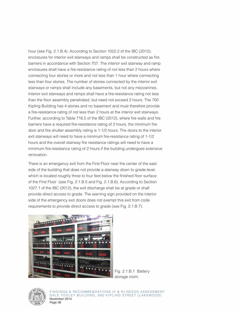
There is a battery storage room in the southeast corner of the First Floor (see
Fig. 2.1.B.1). Compliance with International Building Code and International
Fire Code requirements for stationary storage battery systems should be
verified as part of any future renovation plan.
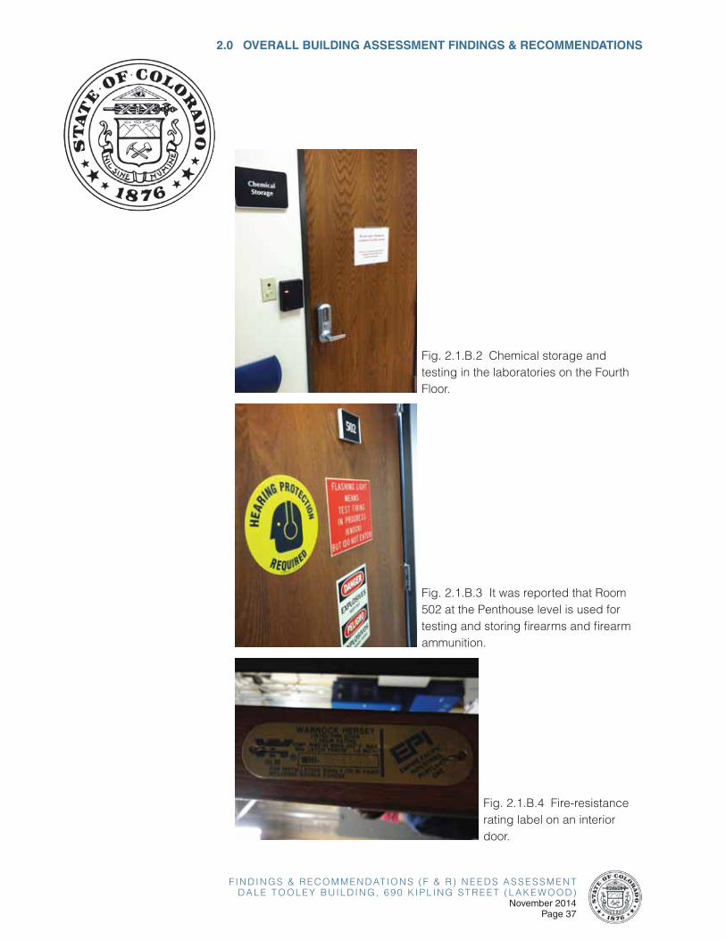
Unknown chemicals are being stored and tested in the laboratories on
the Fourth Floor (see Fig. 2.1.B.2). There is also an area located at the
Penthouse level in Room 502 where the testing of firearms and firearm
ammunition takes place (see Fig. 2.1.B.3). Compliance with International
Building Code, International Fire Code, and any applicable Life Safety Code
requirements for storage of hazardous materials should be verified as part of
any future renovation plan.
F I N D I N G S & R E C O M M E N D AT I O N S ( F & R ) N E E D S A S S E S S M E N TD A L E T O O L E Y B U I L D I N G , 6 9 0 K I P L I N G S T R E E T ( L A K E W O O D )
November 2014Page 35
2.0 OVERALL BUILDING ASSESSMENT FINDINGS & RECOMMENDATIONS
Egress Issues
Alterations, repairs, additions, and changes of occupancy to, or relocation
of, existing buildings and structures shall comply with the current provisions
for alterations, repairs, additions and changes of occupancy or relocation.
As an existing building, the Dale Tooley Building is exempt from current
code requirements for new construction as long as only minimal renovation
is done. If the building undergoes extensive renovation, the following issues
may need to be addressed per current code requirements.
According to Table 1014.3 of the IBC (2012), the common path of egress
travel for a building with an approved sprinkler system in a B-type
occupancy is 100 feet with an occupant load greater than 30. The plans
provided by the Owner appear to indicate that the common paths of egress
travel throughout the building, as it currently exists, comply with this code
requirement. The length of the longest common path of egress travel and
the occupancy loads of each floor should be verified as part of any future
renovation plan.
According to Table 1016.2 of the IBC (2012), the exit access travel distance
in a B-type occupancy with a sprinkler system is 300 feet. The approximate
greatest distance of travel that exists from the most remote point on any
of the Dale Tooley Building’s floor plans to an exit stairway is 163 feet
according to the plans provided by the Owner, which is well within the
300 feet allowed. Depending on the fire-resistance ratings of the interior
exit stairways, the distance of travel through the stairways to a public way
may be included in the greatest distance of travel calculation. If this is the
case, then the approximate greatest distance of travel that exists from the
most remote point on the Fourth Floor to an exit discharge to a public way
(traveling down through the south stairway to the First Floor and out through
the West exit) is 324 feet. If the building undergoes extensive renovation,
the fire rating of the exit stairways could result in the travel distance through
the stairways being included in the exit access travel distance. Assuming
the interior exit stairways meet required fire-resistance ratings, the greatest
distance of travel would only be measured to the exit stairway door instead
of to the public way, which is well within the 300 feet allowed by code. The
length of the greatest distance of travel and the occupancy loads of each
floor should be verified as part of any future renovation plans.
The fire-resistance rating of the doors in the building are listed as 1
F I N D I N G S & R E C O M M E N D AT I O N S ( F & R ) N E E D S A S S E S S M E N TD A L E T O O L E Y B U I L D I N G , 6 9 0 K I P L I N G S T R E E T ( L A K E W O O D )November 2014Page 36
hour (see Fig. 2.1.B.4). According to Section 1022.2 of the IBC (2012),
enclosures for interior exit stairways and ramps shall be constructed as fire
barriers in accordance with Section 707. The interior exit stairway and ramp
enclosures shall have a fire-resistance rating of not less than 2 hours where
connecting four stories or more and not less than 1 hour where connecting
less than four stories. The number of stories connected by the interior exit
stairways or ramps shall include any basements, but not any mezzanines.
Interior exit stairways and ramps shall have a fire-resistance rating not less
than the floor assembly penetrated, but need not exceed 2 hours. The 700
Kipling Building has 4 stories and no basement and must therefore provide
a fire-resistance rating of not less than 2 hours at the interior exit stairways.
Further, according to Table 716.5 of the IBC (2012), where fire walls and fire
barriers have a required fire-resistance rating of 2 hours, the minimum fire
door and fire shutter assembly rating is 1-1/2 hours. The doors to the interior
exit stairways will need to have a minimum fire-resistance rating of 1-1/2
hours and the overall stairway fire resistance ratings will need to have a
minimum fire-resistance rating of 2 hours if the building undergoes extensive
renovation.
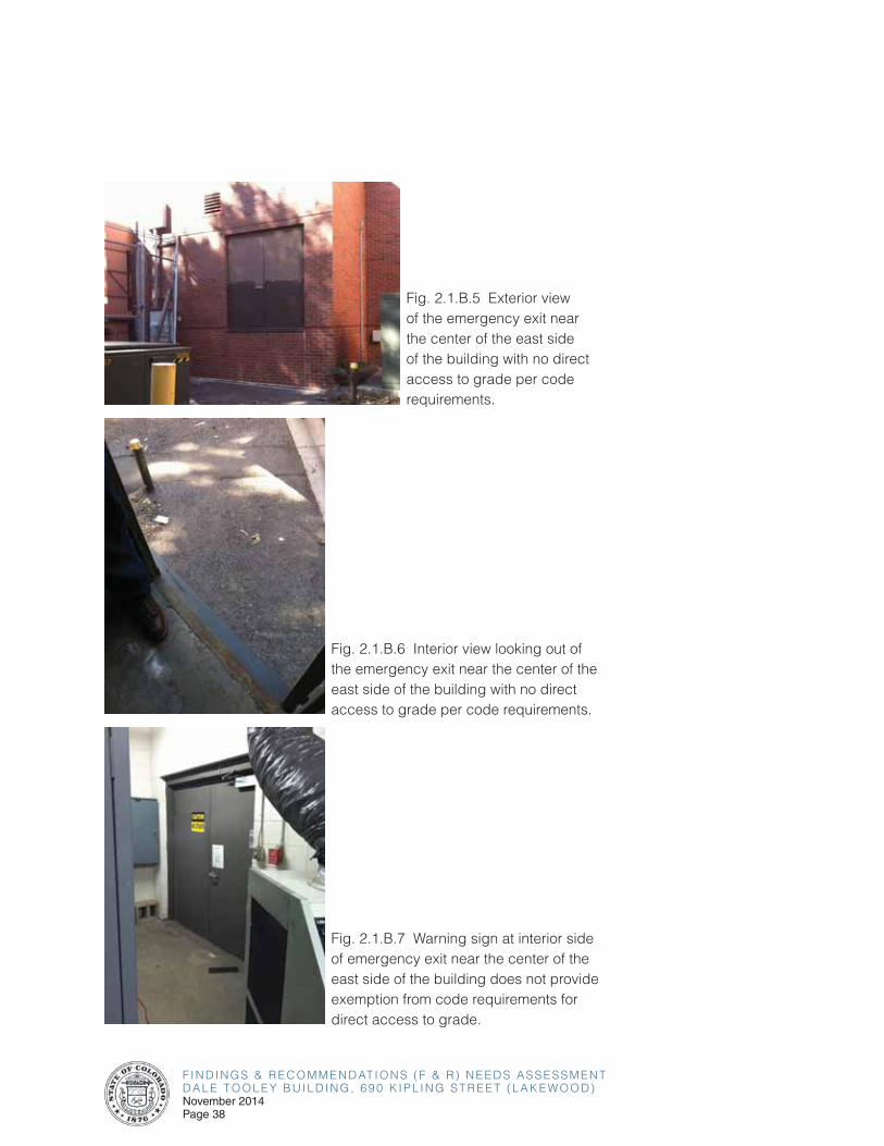
There is an emergency exit from the First Floor near the center of the east
side of the building that does not provide a stairway down to grade level,
which is located roughly three to four feet below the finished floor surface
of the First Floor (see Fig. 2.1.B.5 and Fig. 2.1.B.6). According to Section
1027.1 of the IBC (2012), the exit discharge shall be at grade or shall
provide direct access to grade. The warning sign provided on the interior
side of the emergency exit doors does not exempt this exit from code
requirements to provide direct access to grade (see Fig. 2.1.B.7).
Fig. 2.1.B.1 Battery storage room.
F I N D I N G S & R E C O M M E N D AT I O N S ( F & R ) N E E D S A S S E S S M E N TD A L E T O O L E Y B U I L D I N G , 6 9 0 K I P L I N G S T R E E T ( L A K E W O O D )
November 2014Page 37
Fig. 2.1.B.2 Chemical storage and testing in the laboratories on the Fourth Floor.
2.0 OVERALL BUILDING ASSESSMENT FINDINGS & RECOMMENDATIONS
Fig. 2.1.B.3 It was reported that Room 502 at the Penthouse level is used for testing and storing firearms and firearm ammunition.
Fig. 2.1.B.4 Fire-resistance rating label on an interior door.
F I N D I N G S & R E C O M M E N D AT I O N S ( F & R ) N E E D S A S S E S S M E N TD A L E T O O L E Y B U I L D I N G , 6 9 0 K I P L I N G S T R E E T ( L A K E W O O D )November 2014Page 38
Fig. 2.1.B.5 Exterior view of the emergency exit near the center of the east side of the building with no direct access to grade per code requirements.
Fig. 2.1.B.6 Interior view looking out of the emergency exit near the center of the east side of the building with no direct access to grade per code requirements.
Fig. 2.1.B.7 Warning sign at interior side of emergency exit near the center of the east side of the building does not provide exemption from code requirements for direct access to grade.
F I N D I N G S & R E C O M M E N D AT I O N S ( F & R ) N E E D S A S S E S S M E N TD A L E T O O L E Y B U I L D I N G , 6 9 0 K I P L I N G S T R E E T ( L A K E W O O D )
November 2014Page 39
Recommendations:
• Verify the fire-resistance ratings of the existing interior exit stairways and doors and upgrade as necessary per future renovation plans.
• Verify the presence and extent of any hazardous materials in the laboratories on the Fourth Floor in order to determine the code requirements that would apply to these spaces and to the building.
• Install an exterior stairway at the emergency exit near the center of the east side of the building to provide direct access to grade per code requirements.
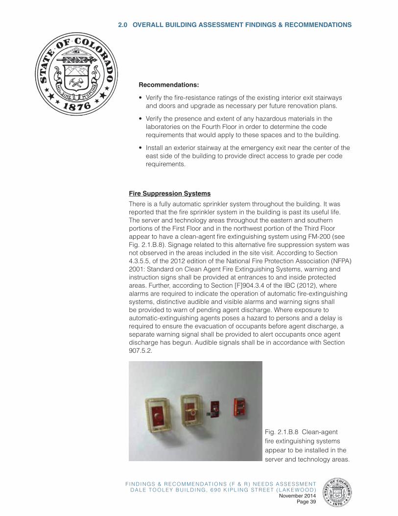
Fire Suppression Systems
There is a fully automatic sprinkler system throughout the building. It was reported that the fire sprinkler system in the building is past its useful life. The server and technology areas throughout the eastern and southern portions of the First Floor and in the northwest portion of the Third Floor appear to have a clean-agent fire extinguishing system using FM-200 (see Fig. 2.1.B.8). Signage related to this alternative fire suppression system was not observed in the areas included in the site visit. According to Section 4.3.5.5, of the 2012 edition of the National Fire Protection Association (NFPA) 2001: Standard on Clean Agent Fire Extinguishing Systems, warning and instruction signs shall be provided at entrances to and inside protected areas. Further, according to Section [F]904.3.4 of the IBC (2012), where alarms are required to indicate the operation of automatic fire-extinguishing systems, distinctive audible and visible alarms and warning signs shall be provided to warn of pending agent discharge. Where exposure to automatic-extinguishing agents poses a hazard to persons and a delay is required to ensure the evacuation of occupants before agent discharge, a separate warning signal shall be provided to alert occupants once agent discharge has begun. Audible signals shall be in accordance with Section 907.5.2.
2.0 OVERALL BUILDING ASSESSMENT FINDINGS & RECOMMENDATIONS
Fig. 2.1.B.8 Clean-agent fire extinguishing systems appear to be installed in the server and technology areas.
F I N D I N G S & R E C O M M E N D AT I O N S ( F & R ) N E E D S A S S E S S M E N TD A L E T O O L E Y B U I L D I N G , 6 9 0 K I P L I N G S T R E E T ( L A K E W O O D )November 2014Page 40
Recommendations:
• Provide signage for the alternative fire suppression systems in the server and technology areas throughout the building per National Fire Protection Association (NFPA) and International Building Code (IBC) requirements.
• Repair or replace the automatic sprinkler system throughout as required to comply with code requirements.
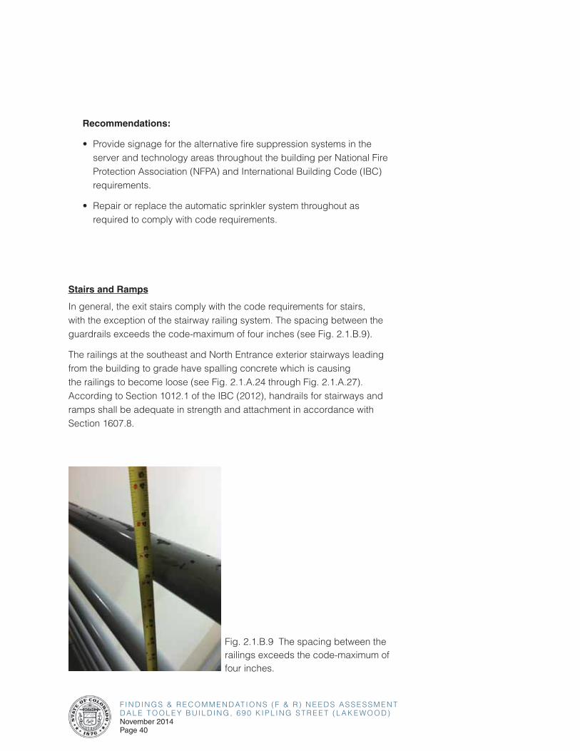
Stairs and Ramps
In general, the exit stairs comply with the code requirements for stairs, with the exception of the stairway railing system. The spacing between the guardrails exceeds the code-maximum of four inches (see Fig. 2.1.B.9).
The railings at the southeast and North Entrance exterior stairways leading from the building to grade have spalling concrete which is causing the railings to become loose (see Fig. 2.1.A.24 through Fig. 2.1.A.27). According to Section 1012.1 of the IBC (2012), handrails for stairways and ramps shall be adequate in strength and attachment in accordance with Section 1607.8.
Fig. 2.1.B.9 The spacing between the railings exceeds the code-maximum of four inches.
F I N D I N G S & R E C O M M E N D AT I O N S ( F & R ) N E E D S A S S E S S M E N TD A L E T O O L E Y B U I L D I N G , 6 9 0 K I P L I N G S T R E E T ( L A K E W O O D )
November 2014Page 41
Recommendations:
• Replace the existing stairway railing system with a new railing system that complies with the code requirements.
• Repair the spalling and cracking concrete at the southeastern and North Entrance exterior stairways and reattach the railing posts to provide a secure handrail per code requirements.
2.0 OVERALL BUILDING ASSESSMENT FINDINGS & RECOMMENDATIONS
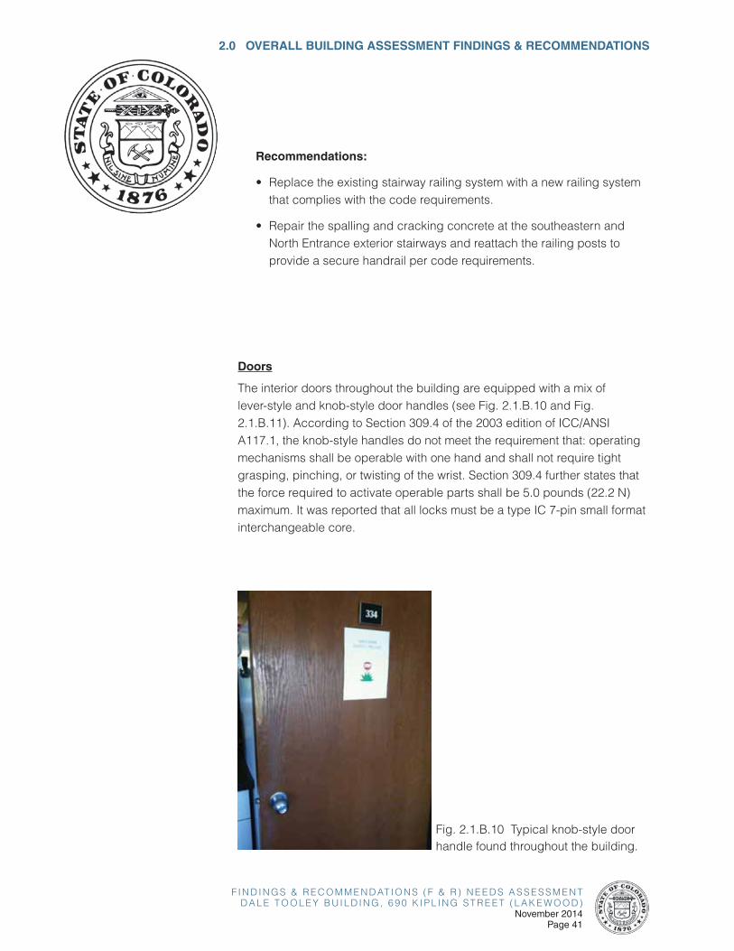
Fig. 2.1.B.10 Typical knob-style door handle found throughout the building.
Doors
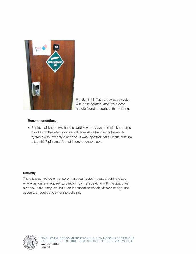
The interior doors throughout the building are equipped with a mix of lever-style and knob-style door handles (see Fig. 2.1.B.10 and Fig. 2.1.B.11). According to Section 309.4 of the 2003 edition of ICC/ANSI A117.1, the knob-style handles do not meet the requirement that: operating mechanisms shall be operable with one hand and shall not require tight grasping, pinching, or twisting of the wrist. Section 309.4 further states that the force required to activate operable parts shall be 5.0 pounds (22.2 N) maximum. It was reported that all locks must be a type IC 7-pin small format interchangeable core.
F I N D I N G S & R E C O M M E N D AT I O N S ( F & R ) N E E D S A S S E S S M E N TD A L E T O O L E Y B U I L D I N G , 6 9 0 K I P L I N G S T R E E T ( L A K E W O O D )November 2014Page 42
Recommendations:
• Replace all knob-style handles and key-code systems with knob-style handles on the interior doors with lever-style handles or key-code systems with lever-style handles. It was reported that all locks must be a type IC 7-pin small format interchangeable core.
Security
There is a controlled entrance with a security desk located behind glass where visitors are required to check in by first speaking with the guard via a phone in the entry vestibule. An identification check, visitor’s badge, and escort are required to enter the building.
Fig. 2.1.B.11 Typical key-code system with an integrated knob-style door handle found throughout the building.
F I N D I N G S & R E C O M M E N D AT I O N S ( F & R ) N E E D S A S S E S S M E N TD A L E T O O L E Y B U I L D I N G , 6 9 0 K I P L I N G S T R E E T ( L A K E W O O D )
November 2014Page 43
2.0 OVERALL BUILDING ASSESSMENT FINDINGS & RECOMMENDATIONS
2.1-C GENERAL ACCESSIBILITY ISSUES
The restrooms throughout the building appear to generally comply with accessibility standards. All of the restrooms are the same throughout the building. There is an additional unisex bathroom with a shower and a unisex locker room on the First Floor. It was noted that the generally accessible restrooms throughout provide one ambulatory accessible toilet compartment per restroom. None of the restrooms in the building provide a wheelchair accessible toilet compartment although there is signage on the restroom doors indicating wheelchair accessibility.
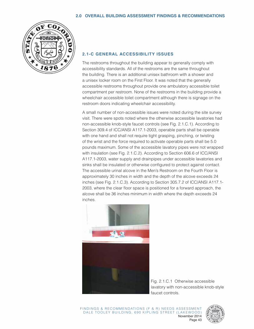
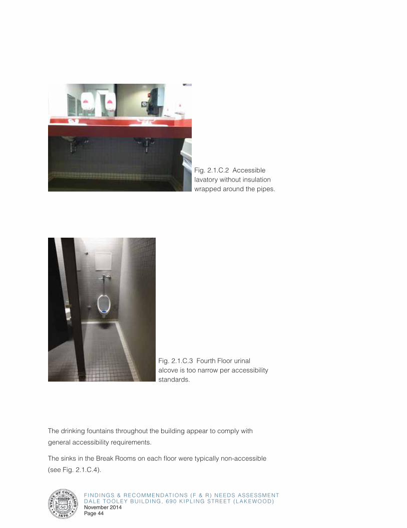
A small number of non-accessible issues were noted during the site survey visit. There were spots noted where the otherwise accessible lavatories had non-accessible knob-style faucet controls (see Fig. 2.1.C.1). According to Section 309.4 of ICC/ANSI A117.1-2003, operable parts shall be operable with one hand and shall not require tight grasping, pinching, or twisting of the wrist and the force required to activate operable parts shall be 5.0 pounds maximum. Some of the accessible lavatory pipes were not wrapped with insulation (see Fig. 2.1.C.2). According to Section 606.6 of ICC/ANSI A117.1-2003, water supply and drainpipes under accessible lavatories and sinks shall be insulated or otherwise configured to protect against contact. The accessible urinal alcove in the Men’s Restroom on the Fourth Floor is approximately 30 inches in width and the depth of the alcove exceeds 24 inches (see Fig. 2.1.C.3). According to Section 305.7.2 of ICC/ANSI A117.1-2003, where the clear floor space is positioned for a forward approach, the alcove shall be 36 inches minimum in width where the depth exceeds 24 inches.
Fig. 2.1.C.1 Otherwise accessible lavatory with non-accessible knob-style faucet controls.
F I N D I N G S & R E C O M M E N D AT I O N S ( F & R ) N E E D S A S S E S S M E N TD A L E T O O L E Y B U I L D I N G , 6 9 0 K I P L I N G S T R E E T ( L A K E W O O D )November 2014Page 44
Fig. 2.1.C.2 Accessible lavatory without insulation wrapped around the pipes.
Fig. 2.1.C.3 Fourth Floor urinal alcove is too narrow per accessibility standards.
The drinking fountains throughout the building appear to comply with
general accessibility requirements.
The sinks in the Break Rooms on each floor were typically non-accessible
(see Fig. 2.1.C.4).

F I N D I N G S & R E C O M M E N D AT I O N S ( F & R ) N E E D S A S S E S S M E N TD A L E T O O L E Y B U I L D I N G , 6 9 0 K I P L I N G S T R E E T ( L A K E W O O D )
November 2014Page 45
Fig. 2.1.C.4 Typical non-accessible sink found in the Break Rooms throughout.
Recommendations:
• Reconfigure restrooms to comply with accessibility guidelines, including providing a minimum of one wheelchair accessible toilet compartment per restroom.
• Replace any knob-style lavatory faucet controls with accessible lever-style faucet controls where not provided.
• Install insulation around accessible lavatory pipes where not provided.
• Reconfigure urinal alcoves to provide the required minimum width per accessibility standards for a forward approach where not provided.
• Install accessible sinks in the Break Rooms throughout where possible.
2.0 OVERALL BUILDING ASSESSMENT FINDINGS & RECOMMENDATIONS
F I N D I N G S & R E C O M M E N D AT I O N S ( F & R ) N E E D S A S S E S S M E N TD A L E T O O L E Y B U I L D I N G , 6 9 0 K I P L I N G S T R E E T ( L A K E W O O D )November 2014Page 46
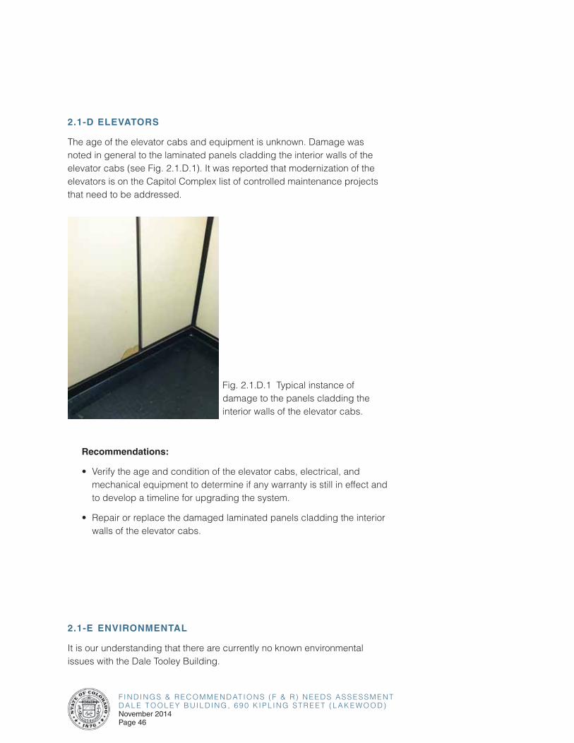
2.1-D ELEVATORS
The age of the elevator cabs and equipment is unknown. Damage was noted in general to the laminated panels cladding the interior walls of the elevator cabs (see Fig. 2.1.D.1). It was reported that modernization of the elevators is on the Capitol Complex list of controlled maintenance projects that need to be addressed.
Fig. 2.1.D.1 Typical instance of damage to the panels cladding the interior walls of the elevator cabs.
Recommendations:
• Verify the age and condition of the elevator cabs, electrical, and mechanical equipment to determine if any warranty is still in effect and to develop a timeline for upgrading the system.
• Repair or replace the damaged laminated panels cladding the interior walls of the elevator cabs.
2.1-E ENVIRONMENTAL
It is our understanding that there are currently no known environmental issues with the Dale Tooley Building.
F I N D I N G S & R E C O M M E N D AT I O N S ( F & R ) N E E D S A S S E S S M E N TD A L E T O O L E Y B U I L D I N G , 6 9 0 K I P L I N G S T R E E T ( L A K E W O O D )
November 2014Page 47
2.0 OVERALL BUILDING ASSESSMENT FINDINGS & RECOMMENDATIONS
2.1-F PLANNED AND ON-GOING PROJECTS
There are no known planned and on-going architectural projects for the building currently.
F I N D I N G S & R E C O M M E N D AT I O N S ( F & R ) N E E D S A S S E S S M E N TD A L E T O O L E Y B U I L D I N G , 6 9 0 K I P L I N G S T R E E T ( L A K E W O O D )November 2014Page 48
2.2 STRUCTURAL
2.2-A EXTERIOR BUILDING ENVELOPE
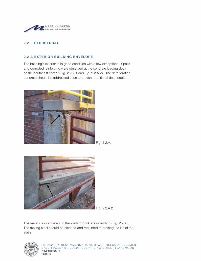
The building’s exterior is in good condition with a few exceptions. Spalls and corroded reinforcing were observed at the concrete loading dock on the southeast corner (Fig. 2.2.A.1 and Fig. 2.2.A.2). The deteriorating concrete should be addressed soon to prevent additional deterioration.
Fig. 2.2.A.1
Fig. 2.2.A.2
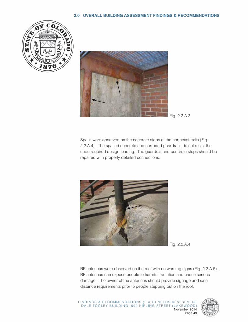
The metal stairs adjacent to the loading dock are corroding (Fig. 2.2.A.3). The rusting steel should be cleaned and repainted to prolong the life of the stairs.
F I N D I N G S & R E C O M M E N D AT I O N S ( F & R ) N E E D S A S S E S S M E N TD A L E T O O L E Y B U I L D I N G , 6 9 0 K I P L I N G S T R E E T ( L A K E W O O D )
November 2014Page 49
2.0 OVERALL BUILDING ASSESSMENT FINDINGS & RECOMMENDATIONS
Fig. 2.2.A.3
Spalls were observed on the concrete steps at the northeast exits (Fig. 2.2.A.4). The spalled concrete and corroded guardrails do not resist the code required design loading. The guardrail and concrete steps should be repaired with properly detailed connections.
Fig. 2.2.A.4
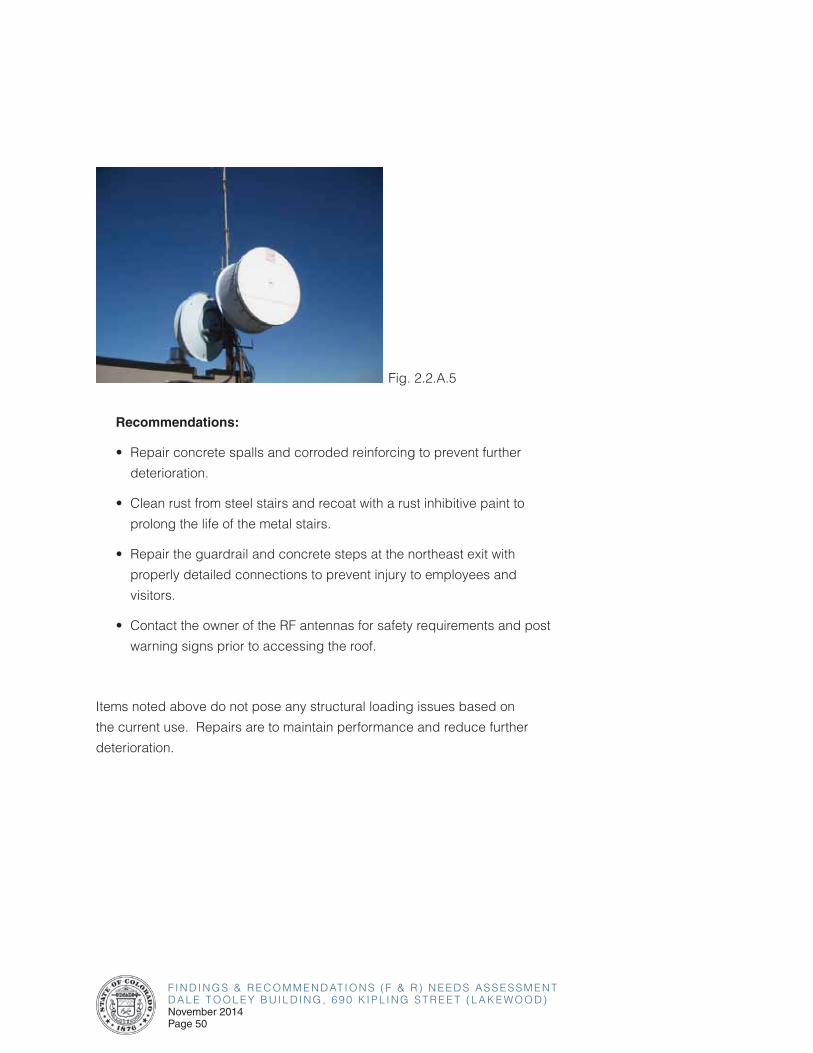
RF antennas were observed on the roof with no warning signs (Fig. 2.2.A.5). RF antennas can expose people to harmful radiation and cause serious damage. The owner of the antennas should provide signage and safe distance requirements prior to people stepping out on the roof.
F I N D I N G S & R E C O M M E N D AT I O N S ( F & R ) N E E D S A S S E S S M E N TD A L E T O O L E Y B U I L D I N G , 6 9 0 K I P L I N G S T R E E T ( L A K E W O O D )November 2014Page 50
Fig. 2.2.A.5
Recommendations:
• Repair concrete spalls and corroded reinforcing to prevent further
deterioration.
• Clean rust from steel stairs and recoat with a rust inhibitive paint to
prolong the life of the metal stairs.
• Repair the guardrail and concrete steps at the northeast exit with
properly detailed connections to prevent injury to employees and
visitors.
• Contact the owner of the RF antennas for safety requirements and post
warning signs prior to accessing the roof.
Items noted above do not pose any structural loading issues based on
the current use. Repairs are to maintain performance and reduce further
deterioration.

F I N D I N G S & R E C O M M E N D AT I O N S ( F & R ) N E E D S A S S E S S M E N TD A L E T O O L E Y B U I L D I N G , 6 9 0 K I P L I N G S T R E E T ( L A K E W O O D )
November 2014Page 51
2.0 OVERALL BUILDING ASSESSMENT FINDINGS & RECOMMENDATIONS
Fig. 2.2.B.1
Recommendations:
• Monitor the crack in the CMU wall for additional movement. Notify structural engineer if crack worsens.
Items noted above do not pose any structural loading issues based on the current use. Repairs are to maintain performance and reduce further deterioration.
2.2-B BUILDING INTERIOR
The overall condition of the structural framing that was readily observable was good. A minor crack was observed in the CMU wall at the northeast exit (Fig. 2.2.B.1). The crack should be monitored for additional movement.
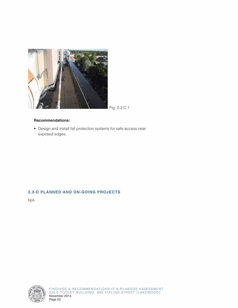
2.2-C FALL PROTECTION
Inadequate parapet heights were observed at the upper and lower roof levels (Fig. 2.2.C.1). The parapet height along the entire roof edge was measured to be approximately 24 inches tall. Parapets should be at least 42 inches tall or fall protection provided for access near the exposed edges
to meet current safety codes.
F I N D I N G S & R E C O M M E N D AT I O N S ( F & R ) N E E D S A S S E S S M E N TD A L E T O O L E Y B U I L D I N G , 6 9 0 K I P L I N G S T R E E T ( L A K E W O O D )November 2014Page 52
Fig. 2.2.C.1
Recommendations:
• Design and install fall protection systems for safe access near exposed edges.
2.2-D PLANNED AND ON-GOING PROJECTS
N/A
F I N D I N G S & R E C O M M E N D AT I O N S ( F & R ) N E E D S A S S E S S M E N TD A L E T O O L E Y B U I L D I N G , 6 9 0 K I P L I N G S T R E E T ( L A K E W O O D )
November 2014Page 53
2.0 OVERALL BUILDING ASSESSMENT FINDINGS & RECOMMENDATIONS
2.3 CIVIL
2.3-A EXTERIOR BUILDING ENVELOPE/SITE
General
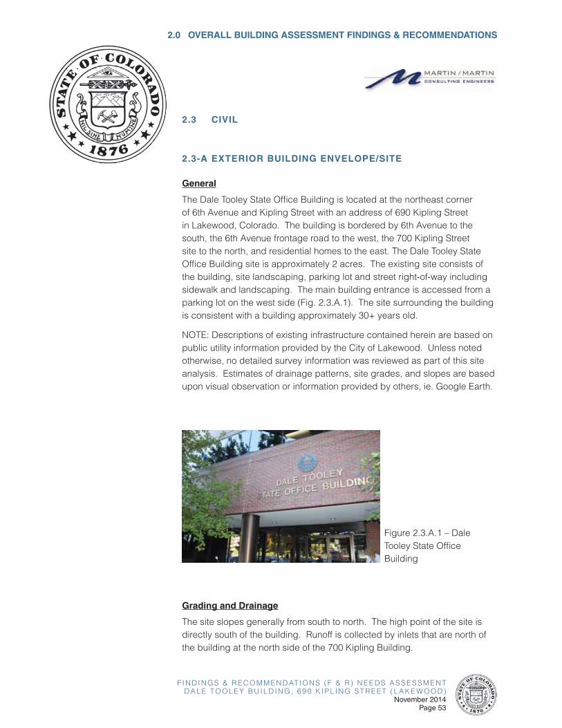
The Dale Tooley State Office Building is located at the northeast corner of 6th Avenue and Kipling Street with an address of 690 Kipling Street in Lakewood, Colorado. The building is bordered by 6th Avenue to the south, the 6th Avenue frontage road to the west, the 700 Kipling Street site to the north, and residential homes to the east. The Dale Tooley State Office Building site is approximately 2 acres. The existing site consists of the building, site landscaping, parking lot and street right-of-way including sidewalk and landscaping. The main building entrance is accessed from a parking lot on the west side (Fig. 2.3.A.1). The site surrounding the building is consistent with a building approximately 30+ years old.
NOTE: Descriptions of existing infrastructure contained herein are based on public utility information provided by the City of Lakewood. Unless noted otherwise, no detailed survey information was reviewed as part of this site analysis. Estimates of drainage patterns, site grades, and slopes are based upon visual observation or information provided by others, ie. Google Earth.
Figure 2.3.A.1 – Dale Tooley State Office Building
Grading and Drainage
The site slopes generally from south to north. The high point of the site is directly south of the building. Runoff is collected by inlets that are north of the building at the north side of the 700 Kipling Building.
F I N D I N G S & R E C O M M E N D AT I O N S ( F & R ) N E E D S A S S E S S M E N TD A L E T O O L E Y B U I L D I N G , 6 9 0 K I P L I N G S T R E E T ( L A K E W O O D )November 2014Page 54
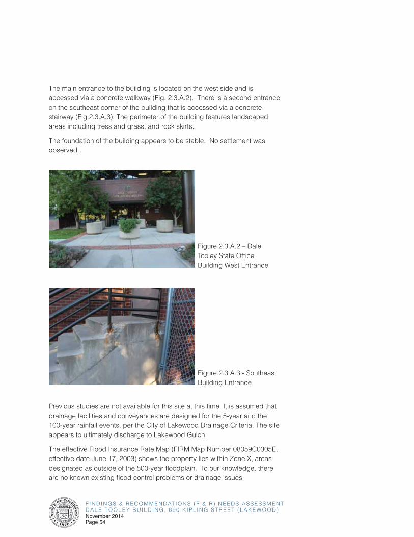
The main entrance to the building is located on the west side and is accessed via a concrete walkway (Fig. 2.3.A.2). There is a second entrance on the southeast corner of the building that is accessed via a concrete stairway (Fig 2.3.A.3). The perimeter of the building features landscaped areas including tress and grass, and rock skirts.
The foundation of the building appears to be stable. No settlement was observed.
Figure 2.3.A.2 – Dale Tooley State Office Building West Entrance
Figure 2.3.A.3 - Southeast Building Entrance
Previous studies are not available for this site at this time. It is assumed that drainage facilities and conveyances are designed for the 5-year and the 100-year rainfall events, per the City of Lakewood Drainage Criteria. The site appears to ultimately discharge to Lakewood Gulch.
The effective Flood Insurance Rate Map (FIRM Map Number 08059C0305E, effective date June 17, 2003) shows the property lies within Zone X, areas designated as outside of the 500-year floodplain. To our knowledge, there are no known existing flood control problems or drainage issues.
F I N D I N G S & R E C O M M E N D AT I O N S ( F & R ) N E E D S A S S E S S M E N TD A L E T O O L E Y B U I L D I N G , 6 9 0 K I P L I N G S T R E E T ( L A K E W O O D )
November 2014Page 55
2.0 OVERALL BUILDING ASSESSMENT FINDINGS & RECOMMENDATIONS
Utility Services
The building utility demands are unknown at this time. The building service line appears to connect to a 6 inch water line to the west of the building which is connected to a 12 inch main that runs through the parking lot and south to 6th Avenue. There are three fire hydrants located near the building. One is on the south edge of the site, another is located southwest of the building and the third is north of the building and is shared with the site for 700 Kipling. There are no known water pressure problems at this time.
The building is served by an 8 inch sanitary sewer line connecting to a 10 inch sanitary sewer main north of the site. Sanitary sewer is routed easterly at an estimated slope between 1 and 3% towards Lakewood High School and Independence Street. There are no known sanitary sewer capacity problems at this time.
Existing storm sewer collects site runoff from 2 inlets located off site to the north. The inlets are located on the 700 Kipling site and collect runoff from both the 690 Kipling and 700 Kipling sites. The first inlet is located in the northwest corner of the site and the other is in the northeast corner of the site. Inlets route runoff via a 12 inch storm sewer to a 48 inch main storm sewer line located north of the 700 Kipling site. The storm sewer is routed easterly along a similar path as the sanitary towards Independence Street. There are no known storm sewer problems at this time.
Existing dry and regulated utilities (electric and telecommunications) are assumed to be located in Kipling Street.
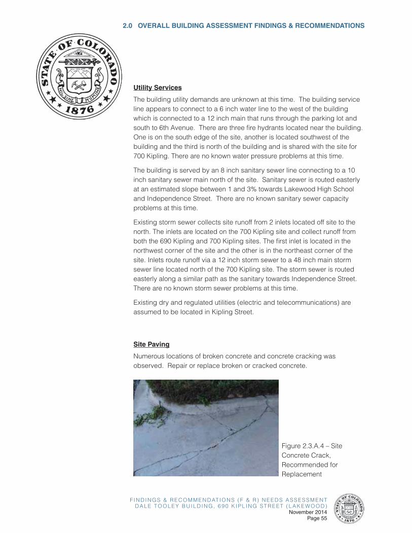
Site Paving
Numerous locations of broken concrete and concrete cracking was observed. Repair or replace broken or cracked concrete.
Figure 2.3.A.4 – Site Concrete Crack, Recommended for Replacement

F I N D I N G S & R E C O M M E N D AT I O N S ( F & R ) N E E D S A S S E S S M E N TD A L E T O O L E Y B U I L D I N G , 6 9 0 K I P L I N G S T R E E T ( L A K E W O O D )November 2014Page 56
Figure 2.3.A.5 – Broken Site Concrete, Recommended for Replacement
Figure 2.3.A.6 – Broken Site Concrete, Recommended for Replacement
Figure 2.3.A.7 – Broken Site Concrete, Recommended for Replacement
F I N D I N G S & R E C O M M E N D AT I O N S ( F & R ) N E E D S A S S E S S M E N TD A L E T O O L E Y B U I L D I N G , 6 9 0 K I P L I N G S T R E E T ( L A K E W O O D )
November 2014Page 57
2.0 OVERALL BUILDING ASSESSMENT FINDINGS & RECOMMENDATIONS
Recommendations:
• Concrete cracks approximately 1/8 inch wide or smaller showing no
differential movement can be sealed using an approved joint sealant.
Cracks should be routed and cleaned per an approved industry
method prior to sealing.
• Concrete panels showing numerous excessive cracking and/or
differential movement should be replaced.
• Replacement of concrete shall be completed in full stone segments,
i.e. to the nearest joint location. Repair the subgrade materials and
place new curb & gutter or sidewalk. Replace backfill materials
and repair/replace any landscaping/paving disturbed during repair
operations.
2.3-B CODE ISSUES
The site exterior was analyzed for general conformance with ADA; however
a complete accessibility audit is not included in the scope of services. The
site appears to comply with current standards.
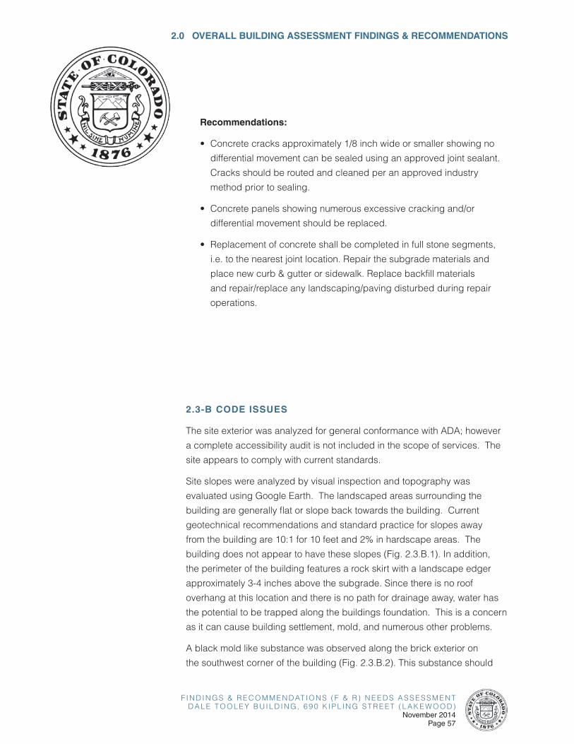
Site slopes were analyzed by visual inspection and topography was
evaluated using Google Earth. The landscaped areas surrounding the
building are generally flat or slope back towards the building. Current
geotechnical recommendations and standard practice for slopes away
from the building are 10:1 for 10 feet and 2% in hardscape areas. The
building does not appear to have these slopes (Fig. 2.3.B.1). In addition,
the perimeter of the building features a rock skirt with a landscape edger
approximately 3-4 inches above the subgrade. Since there is no roof
overhang at this location and there is no path for drainage away, water has
the potential to be trapped along the buildings foundation. This is a concern
as it can cause building settlement, mold, and numerous other problems.
A black mold like substance was observed along the brick exterior on
the southwest corner of the building (Fig. 2.3.B.2). This substance should
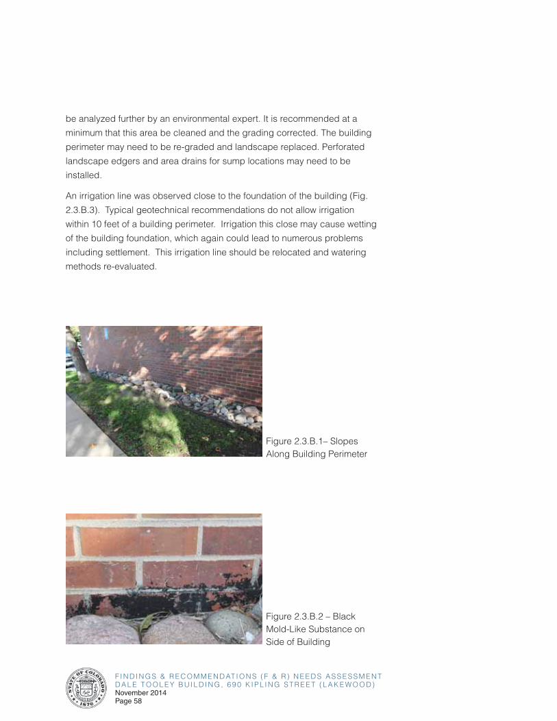
F I N D I N G S & R E C O M M E N D AT I O N S ( F & R ) N E E D S A S S E S S M E N TD A L E T O O L E Y B U I L D I N G , 6 9 0 K I P L I N G S T R E E T ( L A K E W O O D )November 2014Page 58
be analyzed further by an environmental expert. It is recommended at a
minimum that this area be cleaned and the grading corrected. The building
perimeter may need to be re-graded and landscape replaced. Perforated
landscape edgers and area drains for sump locations may need to be
installed.
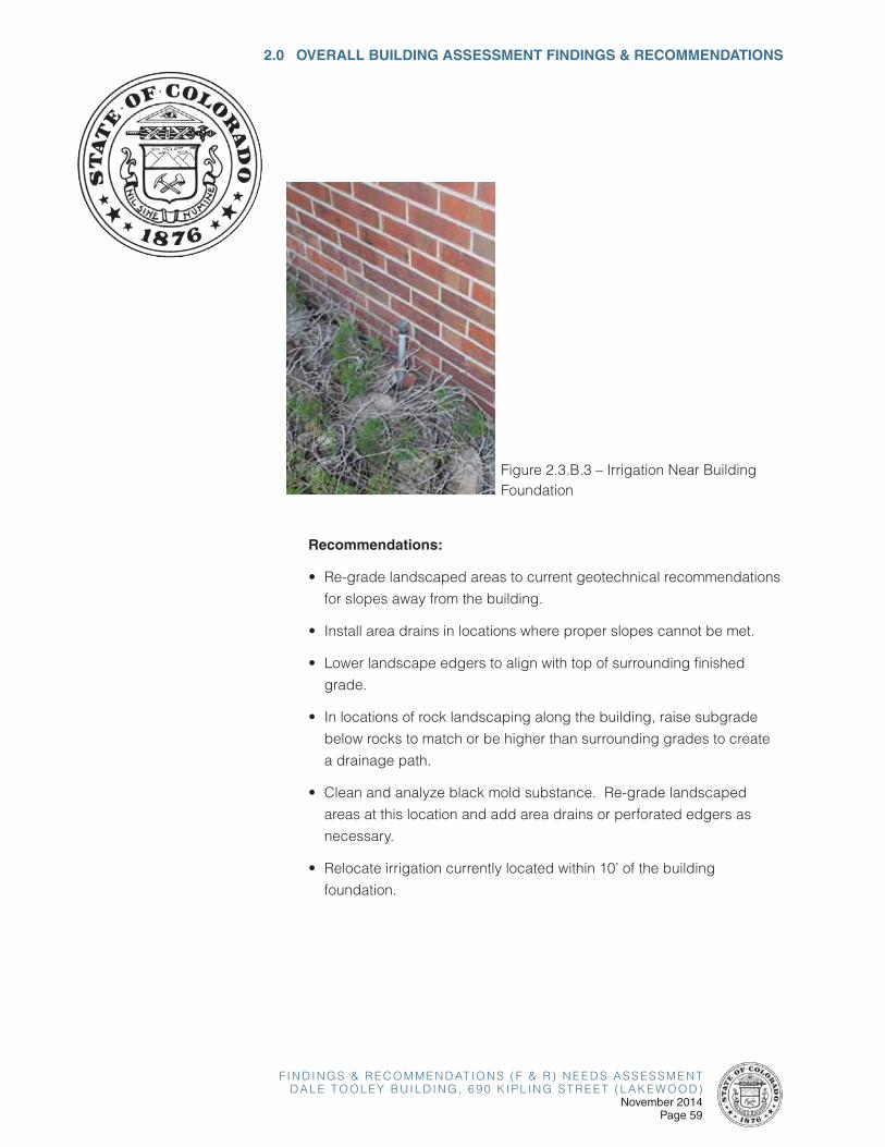
An irrigation line was observed close to the foundation of the building (Fig.
2.3.B.3). Typical geotechnical recommendations do not allow irrigation
within 10 feet of a building perimeter. Irrigation this close may cause wetting
of the building foundation, which again could lead to numerous problems
including settlement. This irrigation line should be relocated and watering
methods re-evaluated.
Figure 2.3.B.1– Slopes Along Building Perimeter
Figure 2.3.B.2 – Black Mold-Like Substance on Side of Building
F I N D I N G S & R E C O M M E N D AT I O N S ( F & R ) N E E D S A S S E S S M E N TD A L E T O O L E Y B U I L D I N G , 6 9 0 K I P L I N G S T R E E T ( L A K E W O O D )
November 2014Page 59
2.0 OVERALL BUILDING ASSESSMENT FINDINGS & RECOMMENDATIONS
Figure 2.3.B.3 – Irrigation Near Building Foundation
Recommendations:
• Re-grade landscaped areas to current geotechnical recommendations
for slopes away from the building.
• Install area drains in locations where proper slopes cannot be met.
• Lower landscape edgers to align with top of surrounding finished
grade.
• In locations of rock landscaping along the building, raise subgrade
below rocks to match or be higher than surrounding grades to create
a drainage path.
• Clean and analyze black mold substance. Re-grade landscaped
areas at this location and add area drains or perforated edgers as
necessary.
• Relocate irrigation currently located within 10’ of the building
foundation.
F I N D I N G S & R E C O M M E N D AT I O N S ( F & R ) N E E D S A S S E S S M E N TD A L E T O O L E Y B U I L D I N G , 6 9 0 K I P L I N G S T R E E T ( L A K E W O O D )November 2014Page 60
2.3-C PLANNED AND ON-GOING PROJECTS
There are no known site planned and on-going projects at this time.
F I N D I N G S & R E C O M M E N D AT I O N S ( F & R ) N E E D S A S S E S S M E N TD A L E T O O L E Y B U I L D I N G , 6 9 0 K I P L I N G S T R E E T ( L A K E W O O D )
November 2014Page 61
2.0 OVERALL BUILDING ASSESSMENT FINDINGS & RECOMMENDATIONS
2.4 MECHANICAL, ELECTRICAL, AND PLUMBING
2.4-A OVERVIEW OF EXISTING SYSTEMS
ELECTRICAL SYSTEMS
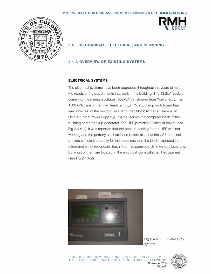
The electrical systems have been upgraded throughout the years to meet
the needs of the departments that work in the building. The 13.2kV feeders
come into the medium voltage 1500kVA transformer from Xcel energy. The
1500 kVA transformer then feeds a 480/277V, 2000 amp switchgear that
feeds the rest of the building including the 208/120V loads. There is an
Uninterrupted Power Supply (UPS) that serves the computer loads in the
building and a backup generator. The UPS provides 625kVA of power (see
Fig 2.4.A.1). It was reported that the backup cooling for the UPS was not
working and the primary unit has failed before also that the UPS does not
provide sufficient capacity for the loads now and the loads expected in the
future and is not redundant. Each floor has panelboards in various locations,
but most of them are located in the electrical room with the IT equipment
(see Fig 2.4.A.2).
Fig 2.4.A.1 – 625kVA UPS system

F I N D I N G S & R E C O M M E N D AT I O N S ( F & R ) N E E D S A S S E S S M E N TD A L E T O O L E Y B U I L D I N G , 6 9 0 K I P L I N G S T R E E T ( L A K E W O O D )November 2014Page 62
Fig 2.4.A.2 – Electrical room panelboards
Recommendations:
• Since many of the panelboards and distribution panels are original to the building, this equipment should be tested and repaired as needed. Per the recommendations of the testing agent, within the next five to ten years, some of the equipment may become more unreliable and will need to be replaced. A scheduled replacement is an option to prevent a failure at an inconvenient time.
• Replace the UPS system to provide enough capacity for the load now and the future load and is redundant.
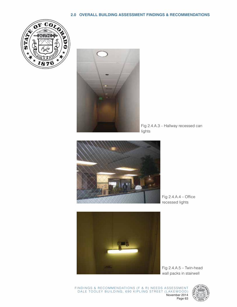
Lighting
In the office, hallways, and other areas, the lighting is provided by fluorescent T8 or compact fluorescent luminaires (see Fig 2.4.A.3 and Fig 2.4.A.4). Most of these luminaires are in good working condition; there were a few lamps that were burned out. Some energy saving automatic occupancy controls observed.
Emergency lighting is provided by a combination of twin-head wall packs and battery ballast in the fixtures (see Fig 2.4.A.5). Most of the twin-head wall packs appear to be original to the building and need to be replaced. The exit signs appear to be in good working condition.
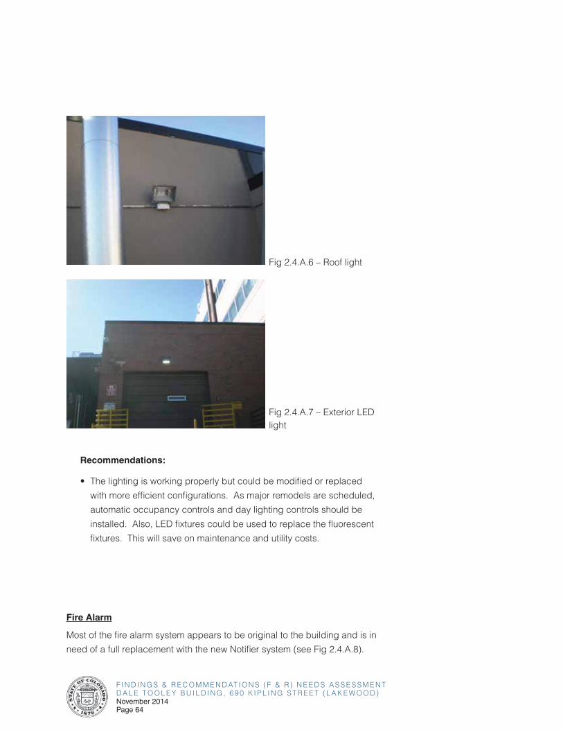
The roof lighting is provided by high intensity discharge (HID) sources (see Fig 2.4.A.6). One exterior light located by the loading dock is an LED type luminaire (see Fig 2.4.A.7). The parking lot lights are metal halide type. The parking lot lights have failed. The conduit system feeding the lights has failed. This will require a complete new parking lot lighting, conduit, and wire system.
F I N D I N G S & R E C O M M E N D AT I O N S ( F & R ) N E E D S A S S E S S M E N TD A L E T O O L E Y B U I L D I N G , 6 9 0 K I P L I N G S T R E E T ( L A K E W O O D )
November 2014Page 63
2.0 OVERALL BUILDING ASSESSMENT FINDINGS & RECOMMENDATIONS
Fig 2.4.A.3 – Hallway recessed can lights
Fig 2.4.A.4 – Office recessed lights
Fig 2.4.A.5 – Twin-head wall packs in stairwell
F I N D I N G S & R E C O M M E N D AT I O N S ( F & R ) N E E D S A S S E S S M E N TD A L E T O O L E Y B U I L D I N G , 6 9 0 K I P L I N G S T R E E T ( L A K E W O O D )November 2014Page 64
Fig 2.4.A.7 – Exterior LED light
Recommendations:
• The lighting is working properly but could be modified or replaced
with more efficient configurations. As major remodels are scheduled,
automatic occupancy controls and day lighting controls should be
installed. Also, LED fixtures could be used to replace the fluorescent
fixtures. This will save on maintenance and utility costs.
Fire Alarm
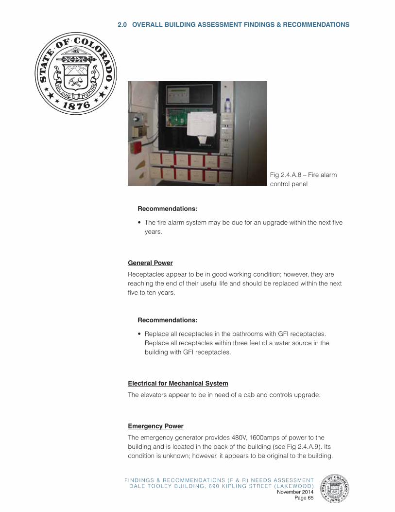
Most of the fire alarm system appears to be original to the building and is in
need of a full replacement with the new Notifier system (see Fig 2.4.A.8).
Fig 2.4.A.6 – Roof light
F I N D I N G S & R E C O M M E N D AT I O N S ( F & R ) N E E D S A S S E S S M E N TD A L E T O O L E Y B U I L D I N G , 6 9 0 K I P L I N G S T R E E T ( L A K E W O O D )
November 2014Page 65
2.0 OVERALL BUILDING ASSESSMENT FINDINGS & RECOMMENDATIONS
Fig 2.4.A.8 – Fire alarm control panel
Recommendations:
• The fire alarm system may be due for an upgrade within the next five years.
General Power
Receptacles appear to be in good working condition; however, they are reaching the end of their useful life and should be replaced within the next five to ten years.
Recommendations:
• Replace all receptacles in the bathrooms with GFI receptacles. Replace all receptacles within three feet of a water source in the building with GFI receptacles.
Electrical for Mechanical System
The elevators appear to be in need of a cab and controls upgrade.
Emergency Power
The emergency generator provides 480V, 1600amps of power to the building and is located in the back of the building (see Fig 2.4.A.9). Its condition is unknown; however, it appears to be original to the building.
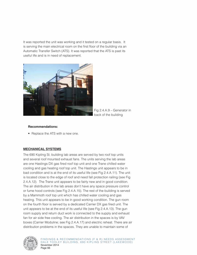
F I N D I N G S & R E C O M M E N D AT I O N S ( F & R ) N E E D S A S S E S S M E N TD A L E T O O L E Y B U I L D I N G , 6 9 0 K I P L I N G S T R E E T ( L A K E W O O D )November 2014Page 66
It was reported the unit was working and it tested on a regular basis. It is serving the main electrical room on the first floor of the building via an Automatic Transfer Switch (ATS). It was reported that the ATS is past its useful life and is in need of replacement.
Fig 2.4.A.9 – Generator in back of the building
Recommendations:
• Replace the ATS with a new one.
MECHANICAL SYSTEMS
The 690 Kipling St. building lab areas are served by two roof top units and several roof mounted exhaust fans. The units serving the lab areas are one Hastings DX gas fired roof top unit and one Trane chilled water cooling and gas heating roof top unit. The Hastings unit appears to be in bad condition and is at the end of its useful life (see Fig 2.4.A.11). The unit is located close to the edge of roof and need fall protection railing (see Fig 2.4.A.12). The Trane unit appears to be fairly new and in good condition. The air distribution in the lab areas don’t have any space pressure control or fume hood controls (see Fig 2.4.A.15). The rest of the building is served by a Mammoth roof top unit which has chilled water cooling and gas heating. This unit appears to be in good working condition. The gun room on the fourth floor is served by a dedicated Carrier DX gas fired unit. The unit appears to be at the end of its useful life (see Fig 2.4.A.13). The gun room supply and return duct work is connected to the supply and exhaust fan for air side free cooling. The air distribution in the spaces is by VAV boxes (Carrier Moduline; see Fig 2.4.A.17) and electric reheat. There are air distribution problems in the spaces. They are unable to maintain some of
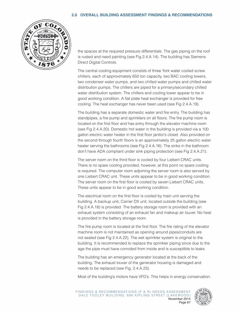
F I N D I N G S & R E C O M M E N D AT I O N S ( F & R ) N E E D S A S S E S S M E N TD A L E T O O L E Y B U I L D I N G , 6 9 0 K I P L I N G S T R E E T ( L A K E W O O D )
November 2014Page 67
2.0 OVERALL BUILDING ASSESSMENT FINDINGS & RECOMMENDATIONS
the spaces at the required pressure differentials. The gas piping on the roof is rusted and need painting (see Fig 2.4.A.14). The building has Siemens Direct Digital Controls.
The central cooling equipment consists of three York water cooled screw chillers, each of approximately 650 ton capacity, two BAC cooling towers, two condenser water pumps, and two chilled water pumps and chilled water distribution pumps. The chillers are piped for a primary/secondary chilled water distribution system. The chillers and cooling tower appear to be in good working condition. A flat plate heat exchanger is provided for free cooling. The heat exchanger has never been used (see Fig 2.4.A.19).
The building has a separate domestic water and fire entry. The building has standpipes, a fire pump and sprinklers on all floors. The fire pump room is located on the first floor and has entry through the elevator machine room (see Fig 2.4.A.20). Domestic hot water in the building is provided via a 100 gallon electric water heater in the first floor janitor’s closet. Also provided on the second through fourth floors is an approximately 25 gallon electric water heater serving the bathrooms (see Fig 2.4.A.16). The sinks in the bathroom don’t have ADA compliant under sink piping protection (see Fig 2.4.A.21).
The server room on the third floor is cooled by four Liebert CRAC units. There is no spare cooling provided, however, at this point no spare cooling is required. The computer room adjoining the server room is also served by one Liebert CRAC unit. These units appear to be in good working condition. The server room on the first floor is cooled by seven Liebert CRAC units. These units appear to be in good working condition.
The electrical room on the first floor is cooled by main unit serving the building. A backup unit, Carrier DX unit, located outside the building (see Fig 2.4.A.18) is provided. The battery storage room is provided with an exhaust system consisting of an exhaust fan and makeup air louver. No heat is provided in the battery storage room.
The fire pump room is located at the first floor. The fire rating of the elevator machine room is not maintained as opening around pipes/conduits are not sealed (see Fig 2.4.A.22). The wet sprinkler system is original to the building. It is recommended to replace the sprinkler piping since due to the age the pipe must have corroded from inside and is susceptible to leaks.
The building has an emergency generator located at the back of the building. The exhaust louver of the generator housing is damaged and needs to be replaced (see Fig. 2.4.A.23).
Most of the building’s motors have VFD’s. This helps in energy conservation.
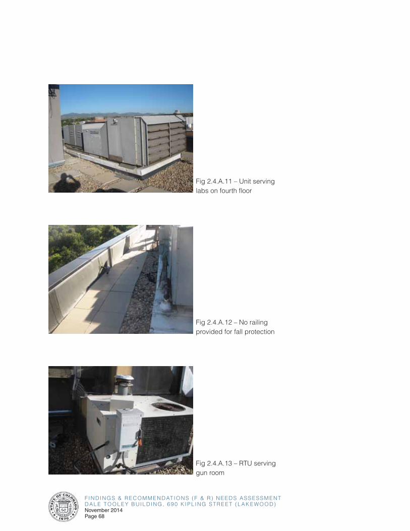
F I N D I N G S & R E C O M M E N D AT I O N S ( F & R ) N E E D S A S S E S S M E N TD A L E T O O L E Y B U I L D I N G , 6 9 0 K I P L I N G S T R E E T ( L A K E W O O D )November 2014Page 68
Fig 2.4.A.11 – Unit serving labs on fourth floor
Fig 2.4.A.12 – No railing provided for fall protection
Fig 2.4.A.13 – RTU serving gun room
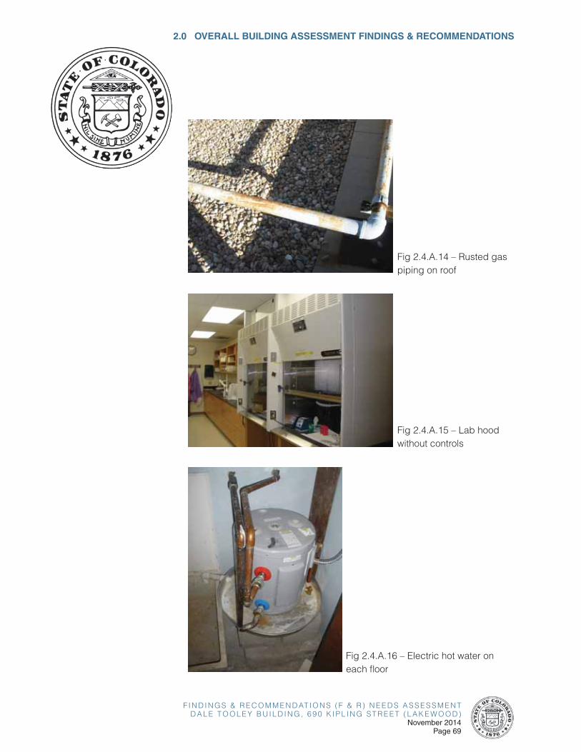
F I N D I N G S & R E C O M M E N D AT I O N S ( F & R ) N E E D S A S S E S S M E N TD A L E T O O L E Y B U I L D I N G , 6 9 0 K I P L I N G S T R E E T ( L A K E W O O D )
November 2014Page 69
2.0 OVERALL BUILDING ASSESSMENT FINDINGS & RECOMMENDATIONS
Fig 2.4.A.14 – Rusted gas piping on roof
Fig 2.4.A.15 – Lab hood without controls
Fig 2.4.A.16 – Electric hot water on each floor
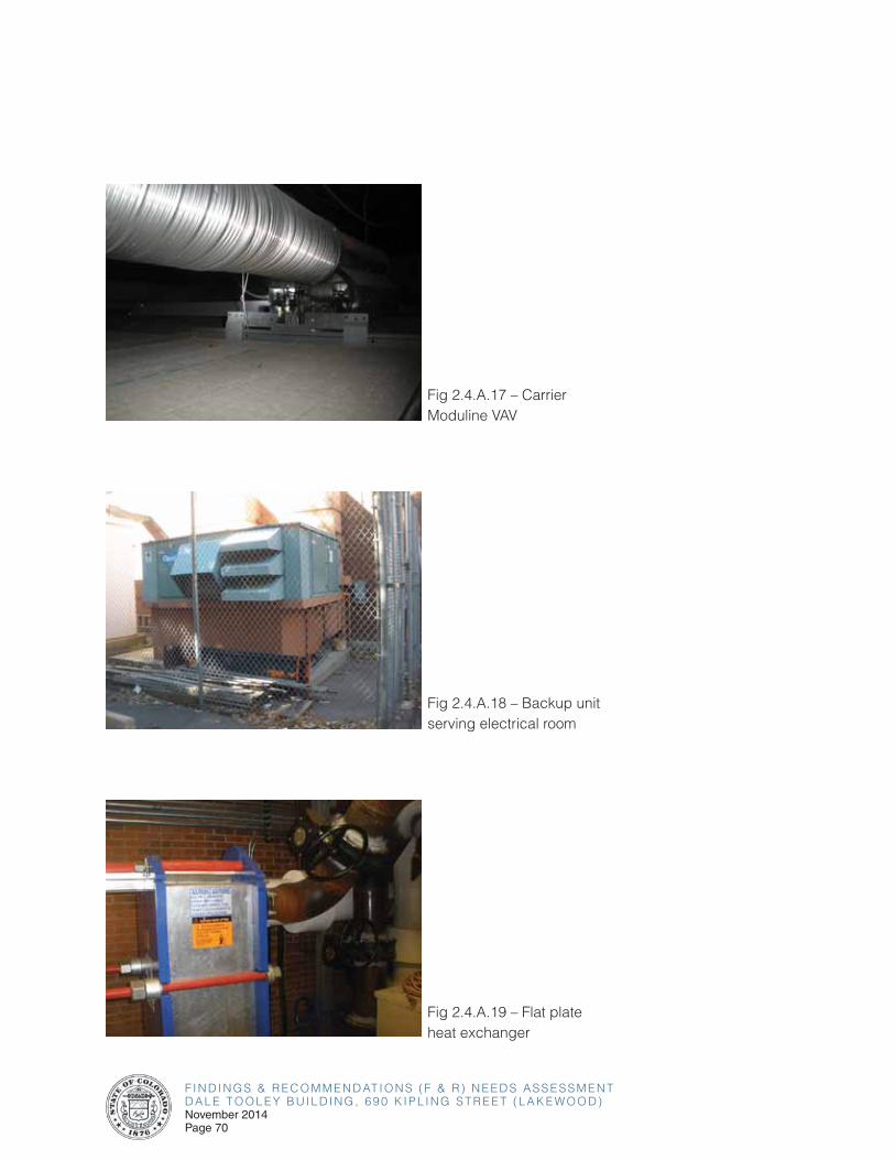
F I N D I N G S & R E C O M M E N D AT I O N S ( F & R ) N E E D S A S S E S S M E N TD A L E T O O L E Y B U I L D I N G , 6 9 0 K I P L I N G S T R E E T ( L A K E W O O D )November 2014Page 70
Fig 2.4.A.17 – Carrier Moduline VAV
Fig 2.4.A.18 – Backup unit serving electrical room
Fig 2.4.A.19 – Flat plate heat exchanger

F I N D I N G S & R E C O M M E N D AT I O N S ( F & R ) N E E D S A S S E S S M E N TD A L E T O O L E Y B U I L D I N G , 6 9 0 K I P L I N G S T R E E T ( L A K E W O O D )
November 2014Page 71
2.0 OVERALL BUILDING ASSESSMENT FINDINGS & RECOMMENDATIONS
Fig 2.4.A.20 – Fire Pump Room
Fig 2.4.A.21 – Under sink piping insulation cover not provided
Fig 2.4.A.22 – Opening around pipes not sealed
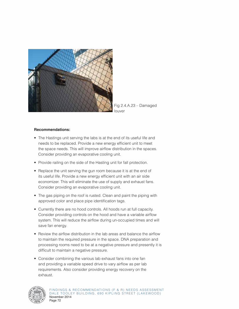
F I N D I N G S & R E C O M M E N D AT I O N S ( F & R ) N E E D S A S S E S S M E N TD A L E T O O L E Y B U I L D I N G , 6 9 0 K I P L I N G S T R E E T ( L A K E W O O D )November 2014Page 72
Recommendations:
• The Hastings unit serving the labs is at the end of its useful life and needs to be replaced. Provide a new energy efficient unit to meet the space needs. This will improve airflow distribution in the spaces. Consider providing an evaporative cooling unit.
• Provide railing on the side of the Hasting unit for fall protection.
• Replace the unit serving the gun room because it is at the end of its useful life. Provide a new energy efficient unit with an air side economizer. This will eliminate the use of supply and exhaust fans. Consider providing an evaporative cooling unit.
• The gas piping on the roof is rusted. Clean and paint the piping with approved color and place pipe identification tags.
• Currently there are no hood controls. All hoods run at full capacity. Consider providing controls on the hood and have a variable airflow system. This will reduce the airflow during un-occupied times and will save fan energy.
• Review the airflow distribution in the lab areas and balance the airflow to maintain the required pressure in the space. DNA preparation and processing rooms need to be at a negative pressure and presently it is difficult to maintain a negative pressure.
• Consider combining the various lab exhaust fans into one fan and providing a variable speed drive to vary airflow as per lab requirements. Also consider providing energy recovery on the exhaust.
Fig 2.4.A.23 – Damaged louver
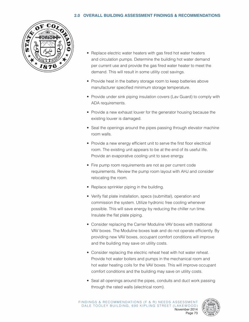
F I N D I N G S & R E C O M M E N D AT I O N S ( F & R ) N E E D S A S S E S S M E N TD A L E T O O L E Y B U I L D I N G , 6 9 0 K I P L I N G S T R E E T ( L A K E W O O D )
November 2014Page 73
2.0 OVERALL BUILDING ASSESSMENT FINDINGS & RECOMMENDATIONS
• Replace electric water heaters with gas fired hot water heaters
and circulation pumps. Determine the building hot water demand
per current use and provide the gas fired water heater to meet the
demand. This will result in some utility cost savings.
• Provide heat in the battery storage room to keep batteries above
manufacturer specified minimum storage temperature.
• Provide under sink piping insulation covers (Lav Guard) to comply with
ADA requirements.
• Provide a new exhaust louver for the generator housing because the
existing louver is damaged.
• Seal the openings around the pipes passing through elevator machine
room walls.
• Provide a new energy efficient unit to serve the first floor electrical
room. The existing unit appears to be at the end of its useful life.
Provide an evaporative cooling unit to save energy.
• Fire pump room requirements are not as per current code
requirements. Review the pump room layout with AHJ and consider
relocating the room.
• Replace sprinkler piping in the building.
• Verify flat plate installation, specs (submittal), operation and
commission the system. Utilize hydronic free cooling whenever
possible. This will save energy by reducing the chiller run time.
Insulate the flat plate piping.
• Consider replacing the Carrier Moduline VAV boxes with traditional
VAV boxes. The Moduline boxes leak and do not operate efficiently. By
providing new VAV boxes, occupant comfort conditions will improve
and the building may save on utility costs.
• Consider replacing the electric reheat heat with hot water reheat.
Provide hot water boilers and pumps in the mechanical room and
hot water heating coils for the VAV boxes. This will improve occupant
comfort conditions and the building may save on utility costs.
• Seal all openings around the pipes, conduits and duct work passing
through the rated walls (electrical room).
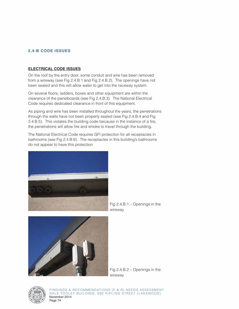
F I N D I N G S & R E C O M M E N D AT I O N S ( F & R ) N E E D S A S S E S S M E N TD A L E T O O L E Y B U I L D I N G , 6 9 0 K I P L I N G S T R E E T ( L A K E W O O D )November 2014Page 74
2.4-B CODE ISSUES
ELECTRICAL CODE ISSUES
On the roof by the entry door, some conduit and wire has been removed from a wireway (see Fig 2.4.B.1 and Fig 2.4.B.2). The openings have not been sealed and this will allow water to get into the raceway system.
On several floors, ladders, boxes and other equipment are within the clearance of the panelboards (see Fig 2.4.B.3). The National Electrical Code requires dedicated clearance in front of this equipment.
As piping and wire has been installed throughout the years, the penetrations through the walls have not been properly sealed (see Fig 2.4.B.4 and Fig 2.4.B.5). This violates the building code because in the instance of a fire, the penetrations will allow fire and smoke to travel through the building.
The National Electrical Code requires GFI protection for all receptacles in bathrooms (see Fig 2.4.B.6). The receptacles in this building’s bathrooms do not appear to have this protection.
Fig 2.4.B.1 – Openings in the wireway
Fig 2.4.B.2 – Openings in the wireway
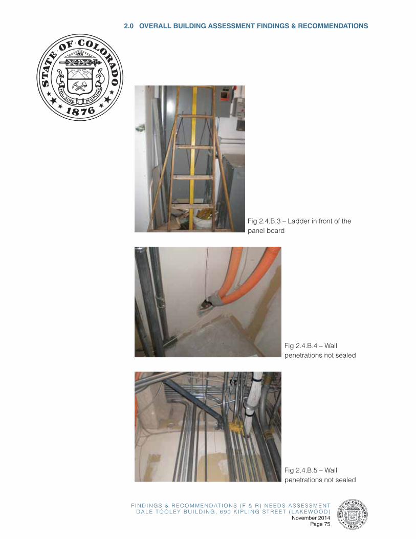
F I N D I N G S & R E C O M M E N D AT I O N S ( F & R ) N E E D S A S S E S S M E N TD A L E T O O L E Y B U I L D I N G , 6 9 0 K I P L I N G S T R E E T ( L A K E W O O D )
November 2014Page 75
2.0 OVERALL BUILDING ASSESSMENT FINDINGS & RECOMMENDATIONS
Fig 2.4.B.3 – Ladder in front of the panel board
Fig 2.4.B.4 – Wall penetrations not sealed
Fig 2.4.B.5 – Wall penetrations not sealed
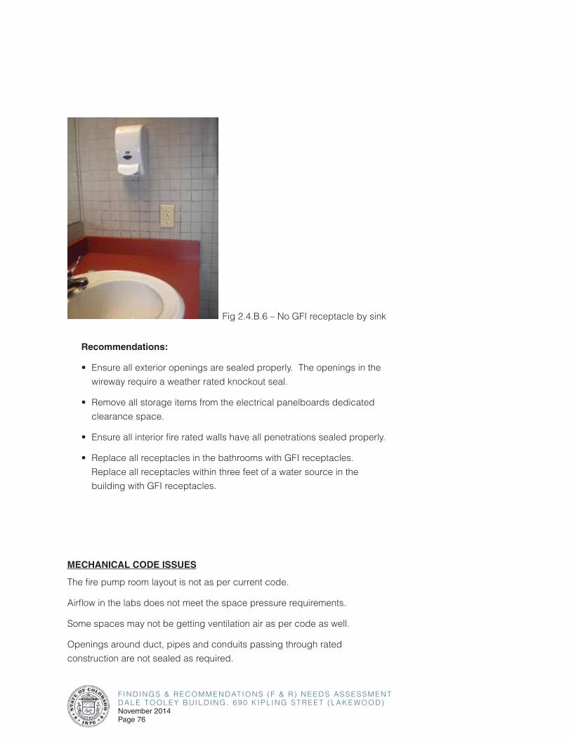
F I N D I N G S & R E C O M M E N D AT I O N S ( F & R ) N E E D S A S S E S S M E N TD A L E T O O L E Y B U I L D I N G , 6 9 0 K I P L I N G S T R E E T ( L A K E W O O D )November 2014Page 76
Recommendations:
• Ensure all exterior openings are sealed properly. The openings in the
wireway require a weather rated knockout seal.
• Remove all storage items from the electrical panelboards dedicated
clearance space.
• Ensure all interior fire rated walls have all penetrations sealed properly.
• Replace all receptacles in the bathrooms with GFI receptacles.
Replace all receptacles within three feet of a water source in the
building with GFI receptacles.
MECHANICAL CODE ISSUES
The fire pump room layout is not as per current code.
Airflow in the labs does not meet the space pressure requirements.
Some spaces may not be getting ventilation air as per code as well.
Openings around duct, pipes and conduits passing through rated
construction are not sealed as required.
Fig 2.4.B.6 – No GFI receptacle by sink
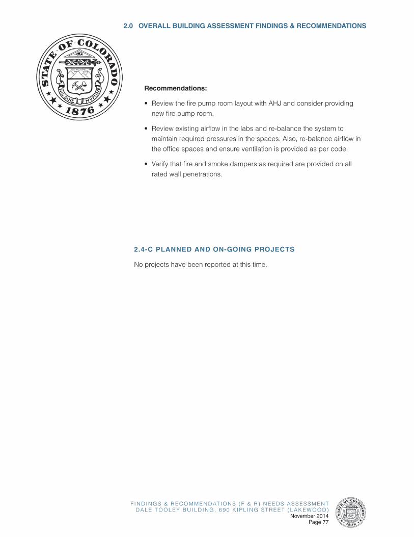
F I N D I N G S & R E C O M M E N D AT I O N S ( F & R ) N E E D S A S S E S S M E N TD A L E T O O L E Y B U I L D I N G , 6 9 0 K I P L I N G S T R E E T ( L A K E W O O D )
November 2014Page 77
2.0 OVERALL BUILDING ASSESSMENT FINDINGS & RECOMMENDATIONS
Recommendations:
• Review the fire pump room layout with AHJ and consider providing
new fire pump room.
• Review existing airflow in the labs and re-balance the system to
maintain required pressures in the spaces. Also, re-balance airflow in
the office spaces and ensure ventilation is provided as per code.
• Verify that fire and smoke dampers as required are provided on all
rated wall penetrations.
2.4-C PLANNED AND ON-GOING PROJECTS
No projects have been reported at this time.
F I N D I N G S & R E C O M M E N D AT I O N S ( F & R ) N E E D S A S S E S S M E N TD A L E T O O L E Y B U I L D I N G , 6 9 0 K I P L I N G S T R E E T ( L A K E W O O D )November 2014Page 78
2.5 VOICE AND DATA
2.5-A OVERVIEW OF EXISTING SYSTEMS
Findings
Note SMW provided voice/data survey and assessment scope for this building on March 28, 2014
• This Data Center is approximately 9075 square feet and this includes the associated warehouse space. The facility was built to house a main frame server system. The main frame has been removed. The overall room floor plan resembles a candy cane with the server room being the top “u” shape and the printer and command spaces being the handle. The command space was created for a quiet space for the operators to gather for meetings, strategies, and monitor disaster recovery from.
• The existing facility lacks a number of power and cooling features in the infrastructure. The only real redundancy can be found the power with two feeds to the building. There is an Automatic transfer Switch (ATO) to transfer power from one utility source to another utility source. An Ideal data center would have redundancy built in to the entire infrastructure eliminating all single points of failure.
• Reportedly, there is a detail report on the building and the entire infrastructure that outlines in more detail the deficiencies that exists. The power distribution is such that the most of the 120/208 volt power utilizes only one transformer. This portion of the power distribution is a single point of failure.
• This facility has a 24 inch high raised floor for both power and data wiring. In some underfloor locations there can be air restrictions due to the volume and concentration of the under floor wiring. The raised floor supporting structure is showing some rust. In some locations under the floor there are significant amounts of abounded cables.
• This facility has a FM 200 fire suppression system. However, there are some pipes in the warehouse into the data center, which do not have fire stopping. These holes will sacrifice the efficiency of the FM 200 system.
F I N D I N G S & R E C O M M E N D AT I O N S ( F & R ) N E E D S A S S E S S M E N TD A L E T O O L E Y B U I L D I N G , 6 9 0 K I P L I N G S T R E E T ( L A K E W O O D )
November 2014Page 79
2.0 OVERALL BUILDING ASSESSMENT FINDINGS & RECOMMENDATIONS
• Rows of server cabinets are not orientated correctly for best cooling air distribution. Some of the rows run east west while others run north south. Currently all of the Computer Room Air Conditioning (CRAC) units are positioned along the south wall. In some server rooms CRAC units are on opposite ends to help on air flow. There are three humidifiers scattered along the walls in the data center to provide humidification to the space. THE CRAC units are part of a chilled water system and the chilled water runs under the raised floor. A water leak detection system is installed under the floor.
• Reportedly, recently a water leak started in an office above the data center. This water leak ended up being a sprinkler head going off as the result of a space heater being left on in the office above.
• With virtualization of the servers, the plan is to move rows of server racks and better orientate them along with reducing their numbers. The UPS system is loaded up to 75% of its capacity. The UPS system is approximately 30 years old.
• Critical applications throughout the state are run from this site. Functions like voting, driver license, HCPF, food stamps, unemployment insurance, etc. This facility is manned 24/7.
• With this data center the Routine problems are: overheating because of the chiller system design, fresh air and night time set back are features of the cooling system which are not desired in the data center for this facility. At one time the facility had a centralized printer in a separate room adjacent to the server room. Printing is now done locally within the building. In the same room tape backup equipment was housed. This equipment has been removed, thus leaving the room vacant for the most part. The printer room and the server room share a wall under the floor for supply are to the equipment in the printer room space. This is significant because of the nearby abandoned cabling affecting the air flow.
• The UPS supports the data center and everything throughout the 690 Kipling facility, items like PCs and anything else that is plugged in. The UPS was designed only to carry the gap between an outage and when the generator power becomes available. In the data center, there are around 650 servers for the major systems. The power to the servers is distributed in the server room via PDUs (power distribution units). The existing PDUs are aging and in some cases, replacement parts are not readily available.
F I N D I N G S & R E C O M M E N D AT I O N S ( F & R ) N E E D S A S S E S S M E N TD A L E T O O L E Y B U I L D I N G , 6 9 0 K I P L I N G S T R E E T ( L A K E W O O D )November 2014Page 80
Recommendations:
The recommendations and guidelines within this section shall establish the Basis of Design for the IT Infrastructure portion of the renovation of the Dale Tooley building.
The building should be provisioned with the following pathways, spaces and cable media.
Telecommunications Rooms (i.e. Spaces)
1. Main Equipment Room (MDF) / Entrance Facility Room (EF)
• One consolidated Main Equipment Room (MDF) / Entrance Facility Room (EF) shall be installed within the building.
• This main MDF room will include both the Building Entrance Facility for supporting outside plant cabling and raceways and will be the main equipment room for installation of the low voltage and communications systems’ (also referred to as the Technology systems) head end equipment.
• The MDF room shall be a minimum of 12’ x 16’ in size, capable of supporting the installation of one row of racks, with approximately six (6) equipment racks / cabinets.
• The MDF room shall be installed on the first floor of the building. Avoid the basement due to potential flooding.
2. Telecommunications Rooms (IDFs)
• A minimum of one (1) telecommunications room (i.e. IDF rooms) will need to be installed on each floor and should be vertically stacked, floor-to-floor. Buildings with larger floor plates may require a 2nd IDF room on each floor, vertically stacked as a 2nd riser within the building.
• The IDF rooms shall be a minimum of 10’ x 12’ in size, capable of supporting the installation of one row of four (4) equipment racks.
3. Telecommunications Room Locations
• The TIA Standards requires one IDF room per floor and it shall be located as close as possible to the center of the area being served, preferably in the core area.
• Additional IDF rooms are required per floor when the floor area served
F I N D I N G S & R E C O M M E N D AT I O N S ( F & R ) N E E D S A S S E S S M E N TD A L E T O O L E Y B U I L D I N G , 6 9 0 K I P L I N G S T R E E T ( L A K E W O O D )
November 2014Page 81
2.0 OVERALL BUILDING ASSESSMENT FINDINGS & RECOMMENDATIONS
exceeds 10,000 square feet or the horizontal distribution distance to the field device or telecom outlet exceeds 295 feet (or 90 meters).
• Telecommunications rooms should not share a common wall with an electrical room due to potential electromagnetic interference (EMI) issues. If it is imperative due to constraints to place both of these rooms adjacent, then a double wall with a 1 foot internal separation should be considered or the layout of the electrical room should preclude mounting of equipment on the common wall.
Telecommunications Pathways (i.e. Conduit/Raceways)
1. Backbone Pathways
• Telecommunications pathways will need to be installed from the MDF room to each IDF room within the building.
• Provide a minimum of three (3) 4 inch conduits from the MDF room to each IDF riser within the building.
• Provide a minimum of three (3) 4 inch conduit sleeves vertically between stacked IDF rooms.
• Provide a telecommunications pathway up to the roof of the building to support future satellite antennas.
2. Horizontal Pathways
• Telecommunications pathways will need to be installed from telecom outlets and IP field devices to the IDF room serving the floor.
• Provide cable tray on each floor within the accessible ceiling spaces of the main corridors as the primary pathways from IDF rooms to telecommunications outlets and field devices.
• Cable tray shall be ladder type aluminum tray with a 9” rung spacing and a width of 18 inches in main corridors and 12 inches in secondary cable tray segments. Cable trays shall be 4 inches in depth.
• For facilities designated as historic buildings, alternate cable routing may require the use of surface mounted conduit and wireways, to comply with historic preservation codes. In these cases, the cable installation design must be coordinated with the State prior to construction.
• At the telecom outlet locations, provide 4” square back boxes that are
F I N D I N G S & R E C O M M E N D AT I O N S ( F & R ) N E E D S A S S E S S M E N TD A L E T O O L E Y B U I L D I N G , 6 9 0 K I P L I N G S T R E E T ( L A K E W O O D )November 2014Page 82
2-1/8” deep with a 1” conduit installed within the wall to the nearest accessible ceiling space, for routing cabling to cable tray.
• If outlets need to be surface mounted then provide 1” surface mounted raceway from the back box to the main telecom distribution pathways.
Telecommunications Cabling
1. Telecommunications Backbone Cables
• Furnish and install a 24-strand singlemode fiber cable and a 24-strand multimode fiber cable from the MDF room to each IDF room in the building. The multimode fiber cable will be OM4 50 micron laser optimized optical fiber.
• Install fiber optic cable in a 1-1/4” innerduct end to end.
• Furnish and install a 50-pair or 100-pair copper backbone cable from the MDF room to each IDF room in the building.
2. Telecommunications Horizontal Cabling
• Furnish and install a Category 6 unshielded, twisted pair (UTP) horizontal cable from telecom outlets and IP field devices to termination hardware in the IDF rooms.
3. Cabling within Single Occupancy Offices
• Provide a minimum of two telecommunications outlets, located on opposite walls, each with two data jacks. Install two Category 6 horizontal cables to each outlet from the IDF room serving the area.
4. Wireless Access Points (WAPs)
• For ceiling mounted WAPs, install two Category 6 horizontal cables to each WAP from the IDF room serving the area.
• Provide WAPs at 200 foot centers on each floor, mounted in accessible ceilings.
F I N D I N G S & R E C O M M E N D AT I O N S ( F & R ) N E E D S A S S E S S M E N TD A L E T O O L E Y B U I L D I N G , 6 9 0 K I P L I N G S T R E E T ( L A K E W O O D )
November 2014Page 83
2.0 OVERALL BUILDING ASSESSMENT FINDINGS & RECOMMENDATIONS
2.5-B CODE ISSUES
Findings
It is our understanding there are currently no major code issues in the building related to the existing voice/data IT/Telecommunications Infrastructure.
Recommendations:
For new renovation work, codes which would be applicable would include buy may not be limited to:
• International Code Council (ICC)
• National Electrical Code (NEC)
• Telecommunications Industry Association (TIA)
• Electronic Industries Alliance (EIA)
• Institute of Electrical and Electronics Engineers (IEEE)
• American National Standards Institute (ANSI)
• Underwriters Laboratories (UL)
• State/Local Governing Authorities Having Jurisdiction
2.5-C PLANNED AND ON-GOING PROJECTS
It is our understanding there are no known planned and/or on-going IT/Telecommunications Infrastructure projects for the Dale Tooley building currently.
F I N D I N G S & R E C O M M E N D AT I O N S ( F & R ) N E E D S A S S E S S M E N TD A L E T O O L E Y B U I L D I N G , 6 9 0 K I P L I N G S T R E E T ( L A K E W O O D )November 2014Page 84
2.6 SECURITY SYSTEMS
2.6-A OVERVIEW OF EXISTING SYSTEMS
Findings
Note SMW not scoped for this task did not provide survey work for Security.
It was reported that Hirsch access control card readers need to be upgraded.
For general security findings, see 2.1-B Code Issues: Security.
Recommendations:
The security systems design guidelines outline electronic security systems infrastructure which would enhance security operations and provide a safe and secure environment for persons and assets within the Dale Tooley building. The purpose of this recommendations report is to provide a description of electronic security system parameters which would provide a safe and secure environment for all those persons and assets within the facilities. It is intended to provide valuable information to both technical and non-technical readers for ongoing coordination with security program requirements.
The security systems should be planned and designed to allow the security personnel the operational flexibility to provide various levels of security based on the threat level at a given time. The systems must further provide capability to deliver the highest quality technology today and in the future for system expansion and change. Security system design shall employ various security technologies. Integrated security systems must be capable to function independently if required, as well as be monitored and controlled from CSP Central Command Center.
Recommended electronic security systems to be considered for implementation and/or upgrade include access control, intrusion detection, duress alarm, intercom, video surveillance, and emergency call system. These applications make it possible for security personnel to view activity both inside and outside the facilities from a central monitoring location or a network-connected security workstation at another location, so they can provide an appropriate response. Care shall be taken to ensure that
F I N D I N G S & R E C O M M E N D AT I O N S ( F & R ) N E E D S A S S E S S M E N TD A L E T O O L E Y B U I L D I N G , 6 9 0 K I P L I N G S T R E E T ( L A K E W O O D )
November 2014Page 85
2.0 OVERALL BUILDING ASSESSMENT FINDINGS & RECOMMENDATIONS
interior and exterior common circulation areas accessible to both staff and public will be properly monitored. Electronic security control and monitoring applications shall be implemented as appropriate to provide a safe and secure environment to the facility as a whole. This report is not designed as a specification, but rather as an outline to provide information on recommended security systems technology and design criteria.
The following security design methodologies, criteria and guidelines should be considered and used in development of the security program and physical/electronic security design for the building:
• Industry Standard / Best Practice Design
• Crime Prevention through Environmental Design (CPTED)
• Layered Security / Concentric Circles of Protection
• Integrated Design – Physical/Electronic/Operational
• ASIS Facilities Physical Security Measures
• IESNA G-1-03 Guideline for Security Lighting
• Unified Facilities Criteria UFC 4-010-01
• State of Colorado Design Standards, as applicable
The access control system (ACS) will be an expansion of the existing campus wide system currently installed throughout other State buildings, and utilize similar ACS door controllers and peripheral equipment. New proximity type card readers shall operate with the existing proximity card credentials. Door devices are to wire through a consolidation junction box above door, and be routed to nearest IDF room where door controllers and power supplies are located. ACS door controllers installed in telecommunications IDF rooms will connect to the buildings LAN for communication with the ACS server. New security equipment to be located within IDF rooms must be coordinated with State IT technical staff. Each access controlled door should be equipped with card reader, electrified lock, door position switch, and request to-exit-motion device (or hardware integral request-to-exit switch). All doors described as a card reader controlled access door will be outfitted with the standard equipment listed, unless specifically defined elsewhere to vary from this configuration. It is recommended that for new controlled doors, magnetic locks and electronic strikes not be used. Electrified lever sets and panic hardware should be equipped with request-to-exit switch in exit hardware. Specific
F I N D I N G S & R E C O M M E N D AT I O N S ( F & R ) N E E D S A S S E S S M E N TD A L E T O O L E Y B U I L D I N G , 6 9 0 K I P L I N G S T R E E T ( L A K E W O O D )November 2014Page 86
door hardware requirements for each controlled door location are to be coordinated with the State. The ACS shall also serve as the primary security management system for monitoring intrusion alarms. Intrusion alarms such as door status and motion detection alarms are to be integrated with and monitored through the access control security management system. Alarm device additions and modifications shall be coordinated with State during the design phase. Security personnel shall be able to monitor security system alarm notification devices through network connected client workstations, where authorized.
The video surveillance system (VSS) will implement IP digital HD type cameras integrated with the existing VSS. Where analog head-end equipment is located, IP camera digital signals are to be decoded to analog video signal. This will allow for future migration from any older analog equipment to an IP based network video solution. IP security video shall be managed by the existing server/recorders, and new network video recorders are to be installed where required to support the addition of new cameras. It is recommended for renovation work that older technology analog camera be replaced with IP digital security camera, connected to the VSS via building LAN. Security cameras may be made up of both fixed field of view and pan-tilt-zoom (PTZ) type, and should be IP, minimum HD quality, and be Power-over-Ethernet (PoE) devices. Camera network cabling shall pull to nearest IDF room, providing connectivity to the building LAN. IP camera network cabling shall terminate to building PoE network switches. Security personnel shall be able to monitor the security video surveillance system through network connected client workstations, where authorized.
Fixed point duress buttons may be located at designated points within the building, for staff use in emergency situations. Duress alarm buttons should be provided where appropriate, typically at public interface counters and other locations as designated. Duress alarm buttons may be interfaced to the security alarm management system, or intrusion alarm system, and report to a central monitoring station if required.
An Intercom Communication System (ICS) should be implemented to enhance security operations in the facility, for security personnel, staff and visitors. It is strongly recommended that an Intercom over IP (IoIP) Communications solution be used for this application. And IoIP system would provide superior audio quality utilizing the latest digital technology, and provide much greater flexibility for locating both master and sub-stations anywhere on the local area network via IP communications. Security personnel in CSP CCC would be provided with two-way audio communications to any remote building IP intercom sub-station.
F I N D I N G S & R E C O M M E N D AT I O N S ( F & R ) N E E D S A S S E S S M E N TD A L E T O O L E Y B U I L D I N G , 6 9 0 K I P L I N G S T R E E T ( L A K E W O O D )
November 2014Page 87
2.0 OVERALL BUILDING ASSESSMENT FINDINGS & RECOMMENDATIONS
Within the building, new head-end security control equipment is to be located in IDF or technology rooms, as coordinated with State IT technical staff. Equipment may include ACS control panels, power supplies, duress alarm panels, network video recorders, and UPS units. All critical electronic security equipment must be backed-up with emergency power circuits or UPS units. State security personnel and other authorized staff may remotely monitor access control events, system alarms, and security video through network connected client workstations. For building renovation work, requirements for security device additions/upgrades and specific security system functionality are to be coordinated with State security personnel during design and construction phases.
The security systems described above are generally controlled and monitored centrally, primarily from Colorado State Patrol’s Central Command Center (CCC), located in Denver CO. This should be confirmed for this facility prior to programming security criteria. The above listed security applications must be evaluated during renovation project schematic design phases to confirm applicability to the most current State electronic security systems standards. For any renovation work, security contractors should be pre-qualified prior to bidding, and will be required to work very closely with State security personnel during installation, commissioning and testing phases. All security installation work, construction standards, and operation requirements are to be closely coordinated with the State by the electronic security integrator.
Electronic security systems provided for the Dale Tooley building shall be an extension of existing State facility security system infrastructure, as described earlier in the report. It is generally recommended that the building be provided with electronic security applications and equipment as listed below:
Access controlled doors:
• Main entry
• Suite entries on each floor
• IDF rooms, recommended
• Sensitive spaces
Intrusion alarms:
• Access controlled doors
F I N D I N G S & R E C O M M E N D AT I O N S ( F & R ) N E E D S A S S E S S M E N TD A L E T O O L E Y B U I L D I N G , 6 9 0 K I P L I N G S T R E E T ( L A K E W O O D )November 2014Page 88
• Emergency egress only doors
• Perimeter doors
Intercom stations:
• Main entry, recommended
• Receiving dock door, recommended
Duress alarms:
• Public interface counters
• Cash handling locations
• Loading docks
Video surveillance cameras:
• Perimeter entry/exit doors
• Entry lobby/reception
• Elevator lobbies
• Emergency exit doors
• Loading docks
• Building exteriors
Security system cabling should generally share cable routes with that of the building structured network cabling system. The network cabling paths and riser locations generally provides the most direct route through a facility, and typically contain sufficient space for security cabling requirements. For facilities designated as historic buildings, alternate cable routing may require the use of surface mounted conduit and wireways, to comply with historic preservation codes. In these cases, the cable installation design must be coordinated with the State prior to construction. Data cabling required for IP security cameras should be provided and installed by the Telecommunications Contractor. This is the recommended design and construction method for provisioning of the IP camera network cabling to
F I N D I N G S & R E C O M M E N D AT I O N S ( F & R ) N E E D S A S S E S S M E N TD A L E T O O L E Y B U I L D I N G , 6 9 0 K I P L I N G S T R E E T ( L A K E W O O D )
November 2014Page 89
2.0 OVERALL BUILDING ASSESSMENT FINDINGS & RECOMMENDATIONS
support the VSS cabling infrastructure. State IT construction standards for network and security cabling types and jacket color must be adhered to. Security cabling should never be exposed and should be contained in protective conduit wherever cable is accessible to vandalism, accidental damage, or where it traverses any unsecured space. Security cabling shall be plenum rated where required by codes.
The security conduit pathway system should be coordinated with the electrical distribution system in order to maintain separation from motors or transformers, separation between parallel runs of telecommunications and electrical cabling, and separation from fluorescent lights.
Basic Security Conduit requirements:
• All security cabling located in in-accessible spaces shall be installed in conduit.
• All exposed security system cabling and shall be installed in conduit.
• All security system conduits shall be minimum ¾” unless otherwise required.
• All penetrations of rated walls shall be fire-stopped in an approved manner to prevent the passage of flame, smoke, and gas.
Head-end security control equipment shall generally be located in Intermediate Distribution Frame (IDF) rooms, or other technology rooms. Security equipment locations within IDF rooms must be coordinated with State IT technical staff during design phase. This equipment may include access control panels, duress alarm equipment, power supplies, network video recorders, and UPS units. Specific requirements and locations within the rooms will be determined during the design phase. Security cabling within IDF rooms shall be piped to wire gutters and or security equipment panels. Within IDF rooms, it is anticipated a 4’x8’ section of wall space shall be reserved for security equipment, and supplied with fire treated plywood backboard. All security equipment in the room should be located away from potential sources of electro-mechanical interference (EMI) and water infiltration. Rack mounted security equipment may share space in telecommunication equipment racks, where appropriate, and as coordinated State IT personnel. One dedicated 120VAC 20A power circuit shall generally be required at each security wall board location and at each security equipment rack. In the event of loss of building power, all mission critical electronic security equipment requiring continuous 120VAC power
F I N D I N G S & R E C O M M E N D AT I O N S ( F & R ) N E E D S A S S E S S M E N TD A L E T O O L E Y B U I L D I N G , 6 9 0 K I P L I N G S T R E E T ( L A K E W O O D )November 2014Page 90
shall be provided with back-up UPS units. All UPS units shall be stand-alone units dedicated for security, and shall be sized accordingly based on required run time.
2.6-B CODE ISSUES
Findings
It is our understanding there are currently no code issues in the building related to existing electronic security systems.
Recommendations:
For new renovation work, codes which would be applicable would include but may not be limited to:
• International Code Council (ICC)
• Americans with Disabilities Act (ADA)
• National Fire Alarm and Signaling Code (NFPA 72)
• National Fire Protection Association Life Safety Code (NFPA 101)
• National Electrical Code (NEC)
• Telecommunications Industry Association (TIA)
• Electronic Industries Alliance (EIA)
• American National Standards Institute (ANSI)
• Underwriters Laboratories (UL)
• State/Local Governing Authorities Having Jurisdiction
F I N D I N G S & R E C O M M E N D AT I O N S ( F & R ) N E E D S A S S E S S M E N TD A L E T O O L E Y B U I L D I N G , 6 9 0 K I P L I N G S T R E E T ( L A K E W O O D )
November 2014Page 91
2.0 OVERALL BUILDING ASSESSMENT FINDINGS & RECOMMENDATIONS
2.6-C PLANNED AND ON-GOING PROJECTS
It is our understanding there are no known planned and/or on-going Security System projects for the Dale Tooley building currently.

F I N D I N G S & R E C O M M E N D AT I O N S ( F & R ) N E E D S A S S E S S M E N TD A L E T O O L E Y B U I L D I N G , 6 9 0 K I P L I N G S T R E E T ( L A K E W O O D )November 2014Page 92
This page left intentionally blank.
F I N D I N G S & R E C O M M E N D AT I O N S ( F & R ) N E E D S A S S E S S M E N TD A L E T O O L E Y B U I L D I N G , 6 9 0 K I P L I N G S T R E E T ( L A K E W O O D )
November 2014Page 93
3.0 FLOOR-BY-FLOOR ASSESSMENT FINDINGS & RECOMMENDATIONS
3.0 FLOOR-BY-FLOOR ASSESSMENT FINDINGS AND RECOMENDATIONS
3.0-A CODE ISSUES
See 2.1-B Code Issues
3.0-B GENERAL ACCESSIBILITY ISSUES
See 2.1-C General Accessibility Issues
3.0-C ARCHITECTURAL FINISHES AND INTERIOR COMPONENTS
General Architecture Findings
It was reported that the Fourth Floor was remodeled around mid-July 2013. The remodeled areas appear to include the main corridors, elevator lobby, break room, and restroom entry vestibules. The finishes in the laboratories and restrooms, and the ceilings and doors throughout generally appeared to be original.
It was reported that the battery storage room in the southeast corner of the First Floor needs to be heated in the winter to maintain the necessary cell temperature.
Ceiling Finishes
The gypsum board ceiling in the entrance lobby, elevator lobby, and west corridor on the First Floor is in generally fair condition with soiling noted around the air diffusers (see Fig. 3.0.C.1). The gypsum board ceilings in the elevator lobbies throughout the building are in generally fair condition. There was a missing cover noted at a ceiling access hatch in the elevator lobby on the Fourth Floor (see Fig. 3.0.C.2). The gypsum board ceilings in the restrooms throughout the building are in generally fair condition with the exception of the ceiling in the First Floor Unisex Shower Room which has evidence of water damage (see Fig. 3.0.C.3).
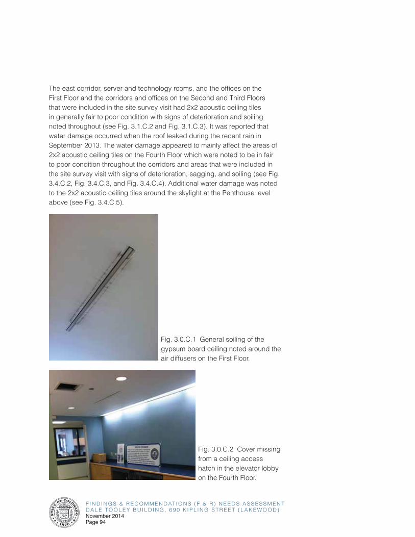
F I N D I N G S & R E C O M M E N D AT I O N S ( F & R ) N E E D S A S S E S S M E N TD A L E T O O L E Y B U I L D I N G , 6 9 0 K I P L I N G S T R E E T ( L A K E W O O D )November 2014Page 94
The east corridor, server and technology rooms, and the offices on the First Floor and the corridors and offices on the Second and Third Floors that were included in the site survey visit had 2x2 acoustic ceiling tiles in generally fair to poor condition with signs of deterioration and soiling noted throughout (see Fig. 3.1.C.2 and Fig. 3.1.C.3). It was reported that water damage occurred when the roof leaked during the recent rain in September 2013. The water damage appeared to mainly affect the areas of 2x2 acoustic ceiling tiles on the Fourth Floor which were noted to be in fair to poor condition throughout the corridors and areas that were included in the site survey visit with signs of deterioration, sagging, and soiling (see Fig. 3.4.C.2, Fig. 3.4.C.3, and Fig. 3.4.C.4). Additional water damage was noted to the 2x2 acoustic ceiling tiles around the skylight at the Penthouse level above (see Fig. 3.4.C.5).
Fig. 3.0.C.1 General soiling of the gypsum board ceiling noted around the air diffusers on the First Floor.
Fig. 3.0.C.2 Cover missing from a ceiling access hatch in the elevator lobby on the Fourth Floor.
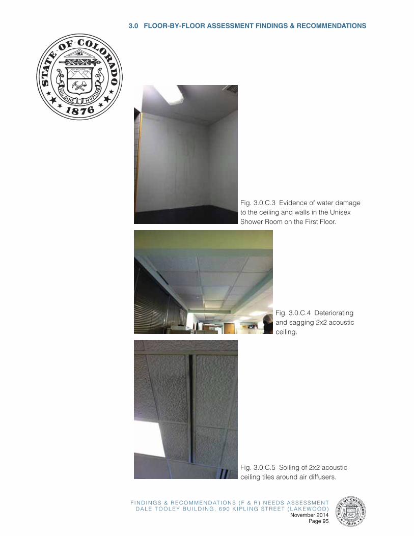
F I N D I N G S & R E C O M M E N D AT I O N S ( F & R ) N E E D S A S S E S S M E N TD A L E T O O L E Y B U I L D I N G , 6 9 0 K I P L I N G S T R E E T ( L A K E W O O D )
November 2014Page 95
Fig. 3.0.C.4 Deteriorating and sagging 2x2 acoustic ceiling.
Fig. 3.0.C.3 Evidence of water damage to the ceiling and walls in the Unisex Shower Room on the First Floor.
3.0 FLOOR-BY-FLOOR ASSESSMENT FINDINGS & RECOMMENDATIONS
Fig. 3.0.C.5 Soiling of 2x2 acoustic ceiling tiles around air diffusers.
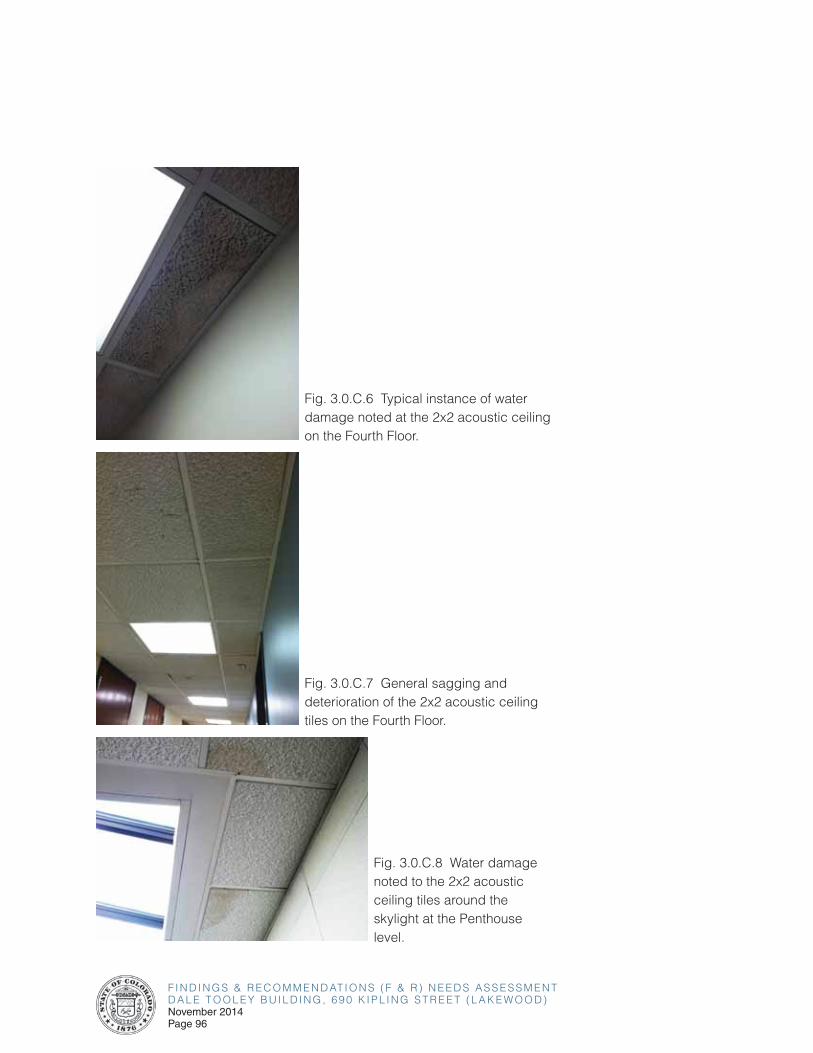
F I N D I N G S & R E C O M M E N D AT I O N S ( F & R ) N E E D S A S S E S S M E N TD A L E T O O L E Y B U I L D I N G , 6 9 0 K I P L I N G S T R E E T ( L A K E W O O D )November 2014Page 96
Fig. 3.0.C.6 Typical instance of water damage noted at the 2x2 acoustic ceiling on the Fourth Floor.
Fig. 3.0.C.7 General sagging and deterioration of the 2x2 acoustic ceiling tiles on the Fourth Floor.
Fig. 3.0.C.8 Water damage noted to the 2x2 acoustic ceiling tiles around the skylight at the Penthouse level.
F I N D I N G S & R E C O M M E N D AT I O N S ( F & R ) N E E D S A S S E S S M E N TD A L E T O O L E Y B U I L D I N G , 6 9 0 K I P L I N G S T R E E T ( L A K E W O O D )
November 2014Page 97
3.0 FLOOR-BY-FLOOR ASSESSMENT FINDINGS & RECOMMENDATIONS
Wall Finishes
The First Floor entrance lobby, elevator lobby, west corridor, and server and technology areas included in the site visit were noted to have gypsum board walls in fair condition. A few areas showed evidence of general wear-and-tear such as scuff marks and minor scrapes (see Fig. 3.0.C.9). There was a loose cord noted hanging out of a hole in the gypsum board wall just south of the First Floor entrance lobby (see Fig. 3.0.C.10). The gypsum board walls and areas of fabric panels cladding the walls in the Second and Third Floor elevator lobbies are in generally fair condition overall. A small area of damage was noted at one of the fabric panels (see Fig. 3.0.C.11). It was reported that all of the fabric should be replaced due to its age and condition. The office areas included in the site survey visit throughout the building were noted to have gypsum board walls in fair condition. An area of the gypsum board wall beneath the drinking fountains on the Third Floor was noted to be missing, exposing the internal elements of the wall (see Fig. 3.0.C.12). The recently painted gypsum board walls in the Fourth Floor elevator lobby, Break Room, and throughout the corridors are in generally good condition overall. The walls in the Fourth Floor laboratory spaces that could be observed through areas of glazing along the main corridors appeared to be in new to fair condition overall.
The wallcovering along the walls and wrapped around the north pair of doors in the First Floor east corridor was in generally poor condition throughout with areas of deterioration, peeling, and damage noted (see Fig. 3.0.C.13). The wallcovering throughout the Second and Third Floor corridors was in generally poor condition overall with areas of deterioration, peeling, and damage noted (see Fig. 3.0.C.14 and Fig. 3.0.C.15). The vinyl baseboard throughout the Second and Third Floor corridors is beginning to pull away from the walls in spots (see Fig. 3.0.C.16).
The gypsum board walls throughout the restrooms on the First Floor are in generally fair condition with the exception of the walls in the First Floor Unisex Shower Room which have evidence of water damage and an area that was repaired but left unfinished (see Fig. 3.0.C.3 and Fig. 3.0.C.17). Some minor damage was also noted to the gypsum board walls in the First Floor Women’s Restroom (see Fig. 3.0.C.18). The gypsum board walls and wallcovering in the Second through Fourth Floor restrooms are in generally fair condition.
The two-inch square wall tile in the restrooms throughout the building is in generally fair condition. An area of residue on the wall tile was noted in the First Floor Women’s Restroom (see Fig. 3.0.C.19).
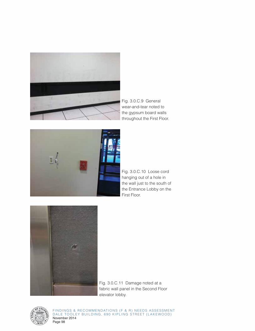
F I N D I N G S & R E C O M M E N D AT I O N S ( F & R ) N E E D S A S S E S S M E N TD A L E T O O L E Y B U I L D I N G , 6 9 0 K I P L I N G S T R E E T ( L A K E W O O D )November 2014Page 98
Fig. 3.0.C.9 General wear-and-tear noted to the gypsum board walls throughout the First Floor.
Fig. 3.0.C.10 Loose cord hanging out of a hole in the wall just to the south of the Entrance Lobby on the First Floor.
Fig. 3.0.C.11 Damage noted at a fabric wall panel in the Second Floor elevator lobby.
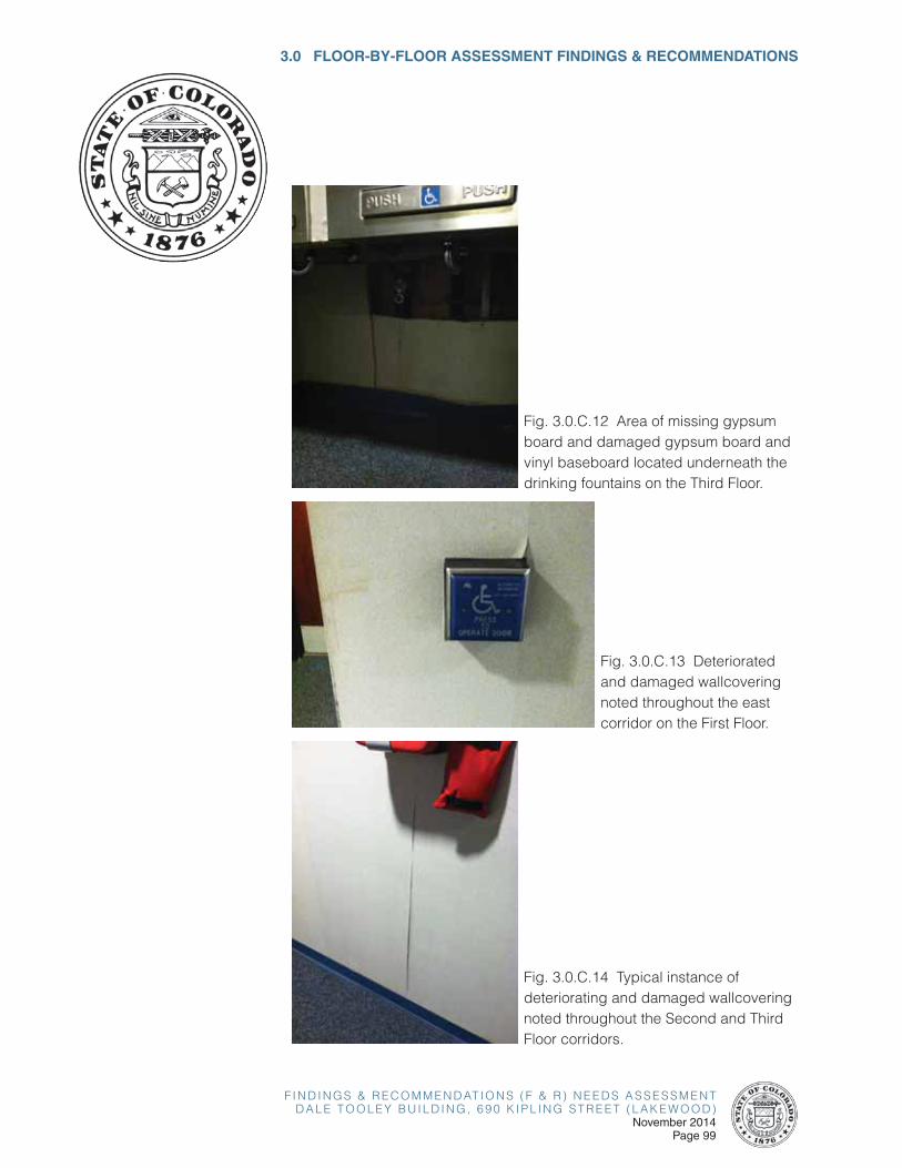
F I N D I N G S & R E C O M M E N D AT I O N S ( F & R ) N E E D S A S S E S S M E N TD A L E T O O L E Y B U I L D I N G , 6 9 0 K I P L I N G S T R E E T ( L A K E W O O D )
November 2014Page 99
3.0 FLOOR-BY-FLOOR ASSESSMENT FINDINGS & RECOMMENDATIONS
Fig. 3.0.C.12 Area of missing gypsum board and damaged gypsum board and vinyl baseboard located underneath the drinking fountains on the Third Floor.
Fig. 3.0.C.13 Deteriorated and damaged wallcovering noted throughout the east corridor on the First Floor.
Fig. 3.0.C.14 Typical instance of deteriorating and damaged wallcovering noted throughout the Second and Third Floor corridors.
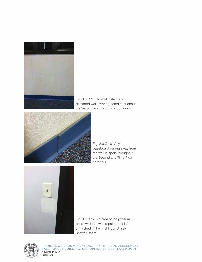
F I N D I N G S & R E C O M M E N D AT I O N S ( F & R ) N E E D S A S S E S S M E N TD A L E T O O L E Y B U I L D I N G , 6 9 0 K I P L I N G S T R E E T ( L A K E W O O D )November 2014Page 100
Fig. 3.0.C.15 Typical instance of damaged wallcovering noted throughout the Second and Third Floor corridors.
Fig. 3.0.C.16 Vinyl baseboard pulling away from the wall in spots throughout the Second and Third Floor corridors.
Fig. 3.0.C.17 An area of the gypsum board wall that was repaired but left unfinished in the First Floor Unisex Shower Room.
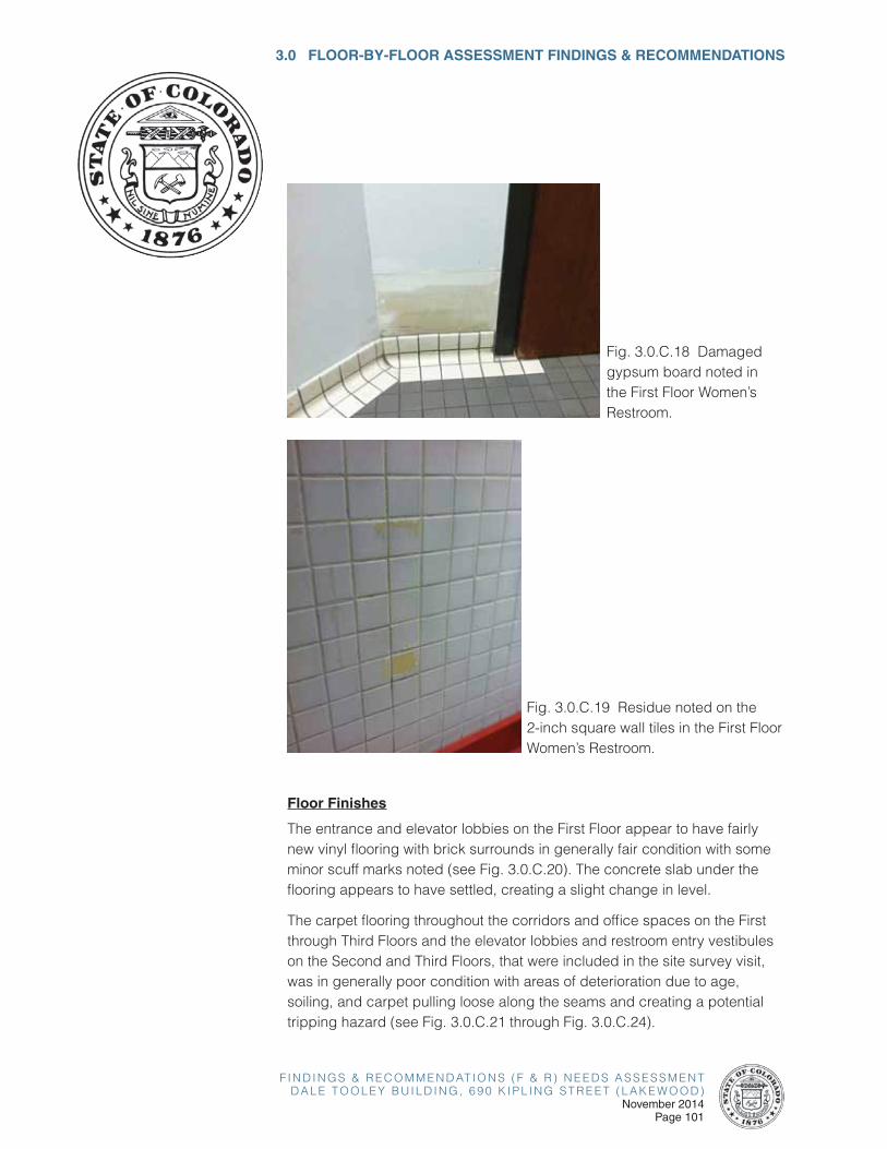
F I N D I N G S & R E C O M M E N D AT I O N S ( F & R ) N E E D S A S S E S S M E N TD A L E T O O L E Y B U I L D I N G , 6 9 0 K I P L I N G S T R E E T ( L A K E W O O D )
November 2014Page 101
3.0 FLOOR-BY-FLOOR ASSESSMENT FINDINGS & RECOMMENDATIONS
Fig. 3.0.C.18 Damaged gypsum board noted in the First Floor Women’s Restroom.
Fig. 3.0.C.19 Residue noted on the 2-inch square wall tiles in the First Floor Women’s Restroom.
Floor Finishes
The entrance and elevator lobbies on the First Floor appear to have fairly new vinyl flooring with brick surrounds in generally fair condition with some minor scuff marks noted (see Fig. 3.0.C.20). The concrete slab under the flooring appears to have settled, creating a slight change in level.
The carpet flooring throughout the corridors and office spaces on the First through Third Floors and the elevator lobbies and restroom entry vestibules on the Second and Third Floors, that were included in the site survey visit, was in generally poor condition with areas of deterioration due to age, soiling, and carpet pulling loose along the seams and creating a potential tripping hazard (see Fig. 3.0.C.21 through Fig. 3.0.C.24).
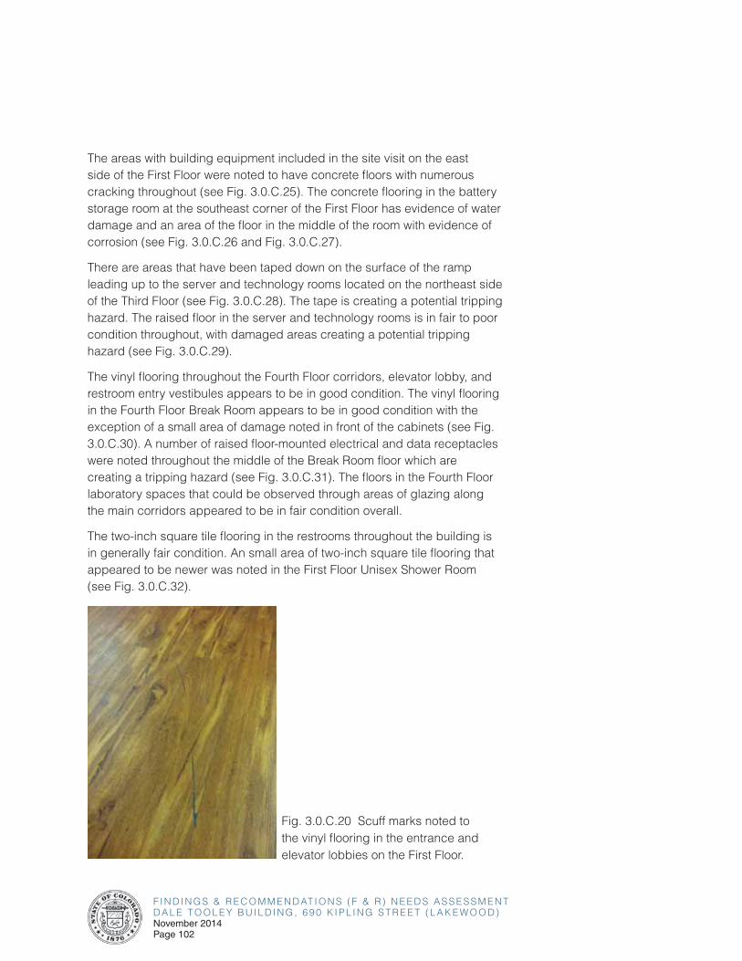
F I N D I N G S & R E C O M M E N D AT I O N S ( F & R ) N E E D S A S S E S S M E N TD A L E T O O L E Y B U I L D I N G , 6 9 0 K I P L I N G S T R E E T ( L A K E W O O D )November 2014Page 102
The areas with building equipment included in the site visit on the east side of the First Floor were noted to have concrete floors with numerous cracking throughout (see Fig. 3.0.C.25). The concrete flooring in the battery storage room at the southeast corner of the First Floor has evidence of water damage and an area of the floor in the middle of the room with evidence of corrosion (see Fig. 3.0.C.26 and Fig. 3.0.C.27).
There are areas that have been taped down on the surface of the ramp leading up to the server and technology rooms located on the northeast side of the Third Floor (see Fig. 3.0.C.28). The tape is creating a potential tripping hazard. The raised floor in the server and technology rooms is in fair to poor condition throughout, with damaged areas creating a potential tripping hazard (see Fig. 3.0.C.29).
The vinyl flooring throughout the Fourth Floor corridors, elevator lobby, and restroom entry vestibules appears to be in good condition. The vinyl flooring in the Fourth Floor Break Room appears to be in good condition with the exception of a small area of damage noted in front of the cabinets (see Fig. 3.0.C.30). A number of raised floor-mounted electrical and data receptacles were noted throughout the middle of the Break Room floor which are creating a tripping hazard (see Fig. 3.0.C.31). The floors in the Fourth Floor laboratory spaces that could be observed through areas of glazing along the main corridors appeared to be in fair condition overall.
The two-inch square tile flooring in the restrooms throughout the building is in generally fair condition. An small area of two-inch square tile flooring that appeared to be newer was noted in the First Floor Unisex Shower Room (see Fig. 3.0.C.32).
Fig. 3.0.C.20 Scuff marks noted to the vinyl flooring in the entrance and elevator lobbies on the First Floor.
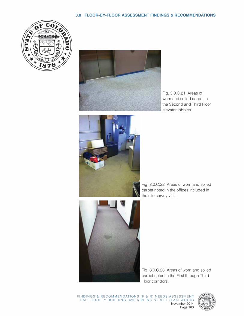
F I N D I N G S & R E C O M M E N D AT I O N S ( F & R ) N E E D S A S S E S S M E N TD A L E T O O L E Y B U I L D I N G , 6 9 0 K I P L I N G S T R E E T ( L A K E W O O D )
November 2014Page 103
3.0 FLOOR-BY-FLOOR ASSESSMENT FINDINGS & RECOMMENDATIONS
Fig. 3.0.C.22 Areas of worn and soiled carpet noted in the offices included in the site survey visit.
Fig. 3.0.C.21 Areas of worn and soiled carpet in the Second and Third Floor elevator lobbies.
Fig. 3.0.C.23 Areas of worn and soiled carpet noted in the First through Third Floor corridors.
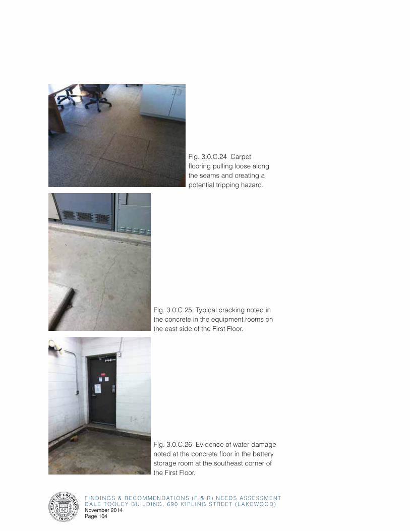
F I N D I N G S & R E C O M M E N D AT I O N S ( F & R ) N E E D S A S S E S S M E N TD A L E T O O L E Y B U I L D I N G , 6 9 0 K I P L I N G S T R E E T ( L A K E W O O D )November 2014Page 104
Fig. 3.0.C.24 Carpet flooring pulling loose along the seams and creating a potential tripping hazard.
Fig. 3.0.C.25 Typical cracking noted in the concrete in the equipment rooms on the east side of the First Floor.
Fig. 3.0.C.26 Evidence of water damage noted at the concrete floor in the battery storage room at the southeast corner of the First Floor.
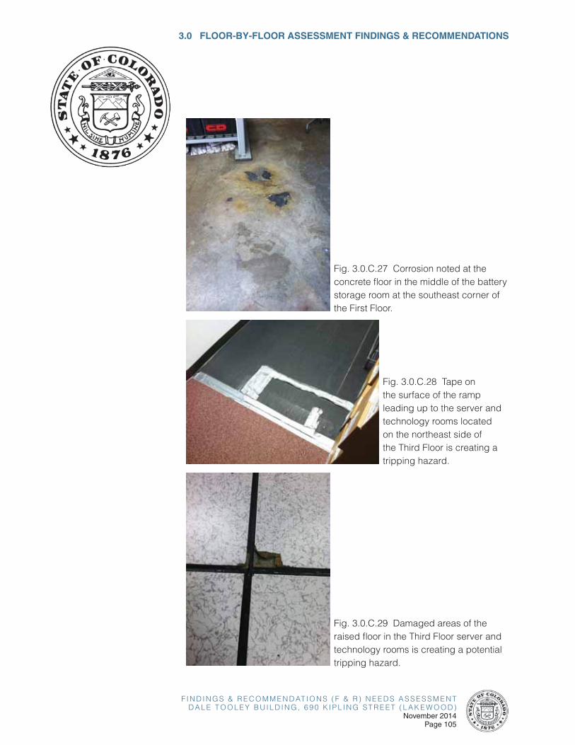
F I N D I N G S & R E C O M M E N D AT I O N S ( F & R ) N E E D S A S S E S S M E N TD A L E T O O L E Y B U I L D I N G , 6 9 0 K I P L I N G S T R E E T ( L A K E W O O D )
November 2014Page 105
3.0 FLOOR-BY-FLOOR ASSESSMENT FINDINGS & RECOMMENDATIONS
Fig. 3.0.C.27 Corrosion noted at the concrete floor in the middle of the battery storage room at the southeast corner of the First Floor.
Fig. 3.0.C.28 Tape on the surface of the ramp leading up to the server and technology rooms located on the northeast side of the Third Floor is creating a tripping hazard.
Fig. 3.0.C.29 Damaged areas of the raised floor in the Third Floor server and technology rooms is creating a potential tripping hazard.
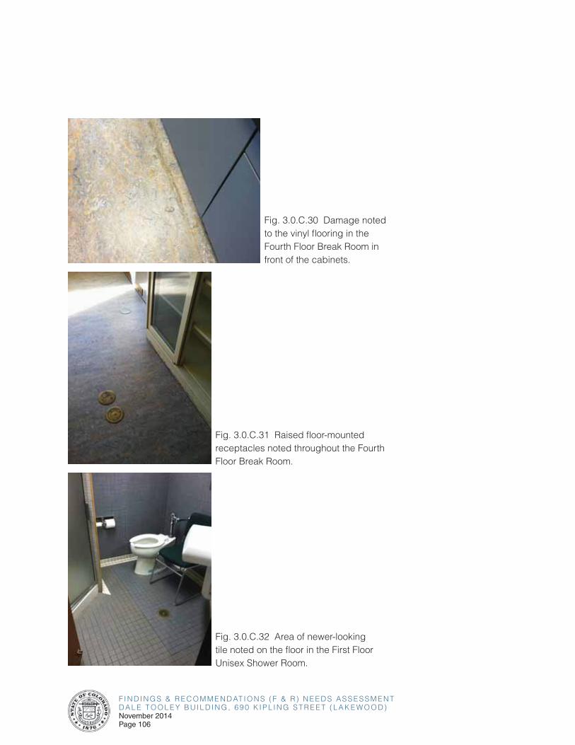
F I N D I N G S & R E C O M M E N D AT I O N S ( F & R ) N E E D S A S S E S S M E N TD A L E T O O L E Y B U I L D I N G , 6 9 0 K I P L I N G S T R E E T ( L A K E W O O D )November 2014Page 106
Fig. 3.0.C.31 Raised floor-mounted receptacles noted throughout the Fourth Floor Break Room.
Fig. 3.0.C.30 Damage noted to the vinyl flooring in the Fourth Floor Break Room in front of the cabinets.
Fig. 3.0.C.32 Area of newer-looking tile noted on the floor in the First Floor Unisex Shower Room.
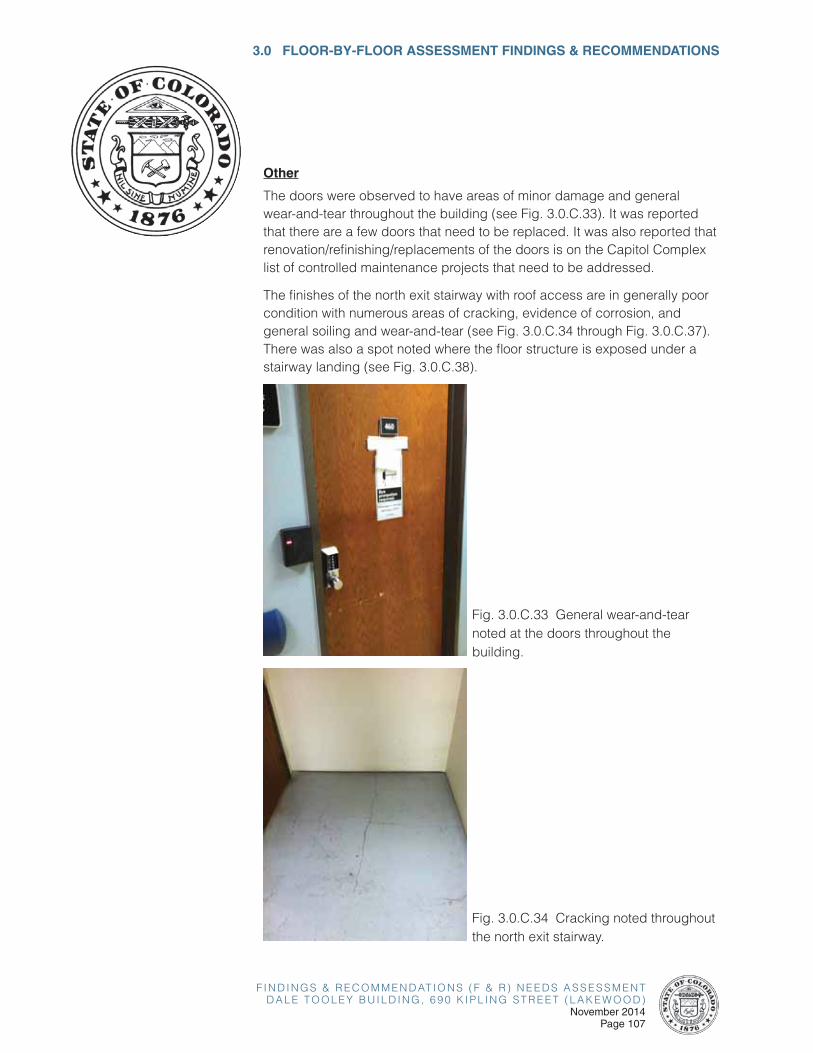
F I N D I N G S & R E C O M M E N D AT I O N S ( F & R ) N E E D S A S S E S S M E N TD A L E T O O L E Y B U I L D I N G , 6 9 0 K I P L I N G S T R E E T ( L A K E W O O D )
November 2014Page 107
3.0 FLOOR-BY-FLOOR ASSESSMENT FINDINGS & RECOMMENDATIONS
Fig. 3.0.C.34 Cracking noted throughout the north exit stairway.
Other
The doors were observed to have areas of minor damage and general wear-and-tear throughout the building (see Fig. 3.0.C.33). It was reported that there are a few doors that need to be replaced. It was also reported that renovation/refinishing/replacements of the doors is on the Capitol Complex list of controlled maintenance projects that need to be addressed.
The finishes of the north exit stairway with roof access are in generally poor condition with numerous areas of cracking, evidence of corrosion, and general soiling and wear-and-tear (see Fig. 3.0.C.34 through Fig. 3.0.C.37). There was also a spot noted where the floor structure is exposed under a stairway landing (see Fig. 3.0.C.38).
Fig. 3.0.C.33 General wear-and-tear noted at the doors throughout the building.

F I N D I N G S & R E C O M M E N D AT I O N S ( F & R ) N E E D S A S S E S S M E N TD A L E T O O L E Y B U I L D I N G , 6 9 0 K I P L I N G S T R E E T ( L A K E W O O D )November 2014Page 108
Fig. 3.0.C.35 Cracking noted throughout the north exit stairway.
Fig. 3.0.C.36 Corrosion noted at the bottom side of the north exit stairway with roof access.
Fig. 3.0.C.37 General soiling and wear-and-tear noted throughout the north exit stairway.
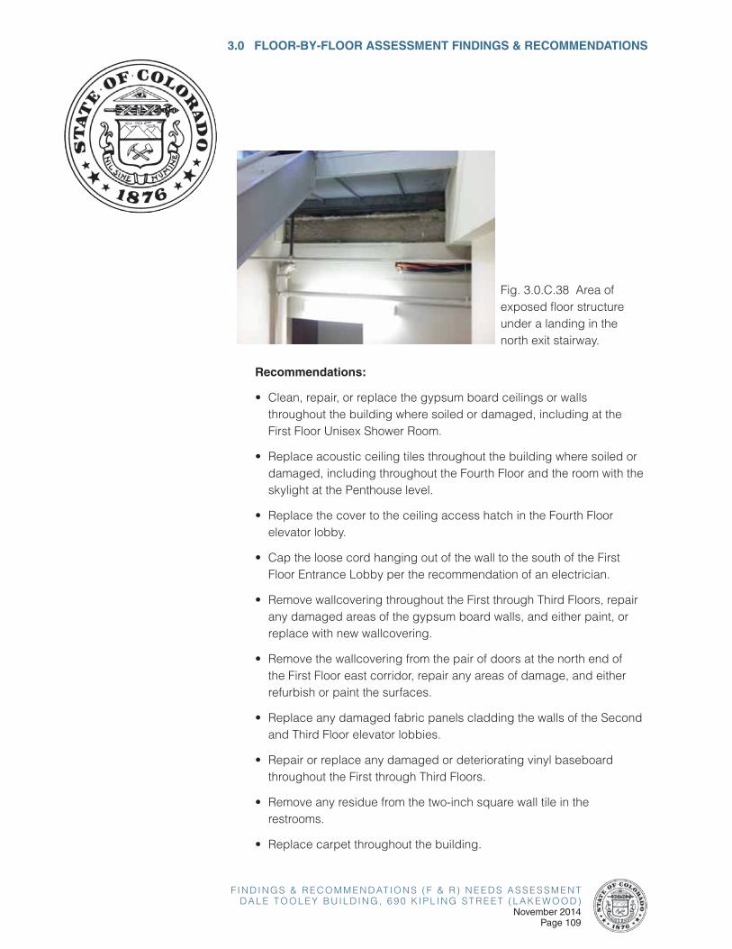
F I N D I N G S & R E C O M M E N D AT I O N S ( F & R ) N E E D S A S S E S S M E N TD A L E T O O L E Y B U I L D I N G , 6 9 0 K I P L I N G S T R E E T ( L A K E W O O D )
November 2014Page 109
3.0 FLOOR-BY-FLOOR ASSESSMENT FINDINGS & RECOMMENDATIONS
Recommendations:
• Clean, repair, or replace the gypsum board ceilings or walls throughout the building where soiled or damaged, including at the First Floor Unisex Shower Room.
• Replace acoustic ceiling tiles throughout the building where soiled or damaged, including throughout the Fourth Floor and the room with the skylight at the Penthouse level.
• Replace the cover to the ceiling access hatch in the Fourth Floor elevator lobby.
• Cap the loose cord hanging out of the wall to the south of the First Floor Entrance Lobby per the recommendation of an electrician.
• Remove wallcovering throughout the First through Third Floors, repair any damaged areas of the gypsum board walls, and either paint, or replace with new wallcovering.
• Remove the wallcovering from the pair of doors at the north end of the First Floor east corridor, repair any areas of damage, and either refurbish or paint the surfaces.
• Replace any damaged fabric panels cladding the walls of the Second and Third Floor elevator lobbies.
• Repair or replace any damaged or deteriorating vinyl baseboard throughout the First through Third Floors.
• Remove any residue from the two-inch square wall tile in the restrooms.
• Replace carpet throughout the building.
Fig. 3.0.C.38 Area of exposed floor structure under a landing in the north exit stairway.
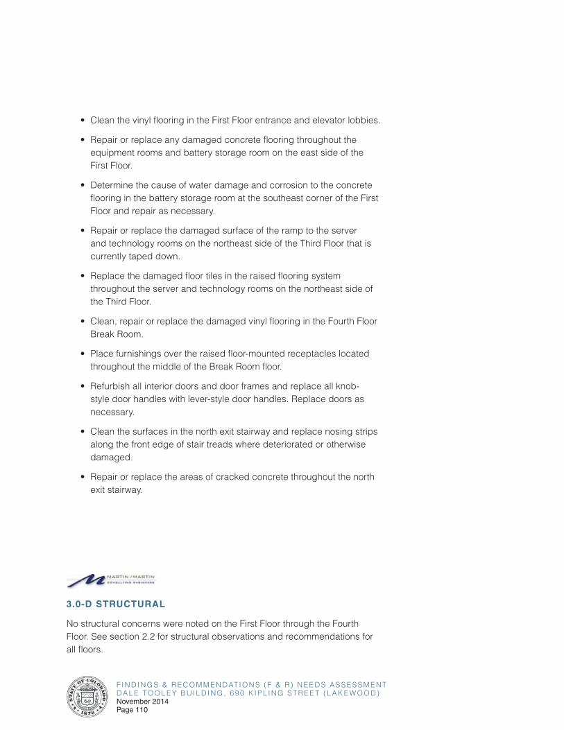
F I N D I N G S & R E C O M M E N D AT I O N S ( F & R ) N E E D S A S S E S S M E N TD A L E T O O L E Y B U I L D I N G , 6 9 0 K I P L I N G S T R E E T ( L A K E W O O D )November 2014Page 110
• Clean the vinyl flooring in the First Floor entrance and elevator lobbies.
• Repair or replace any damaged concrete flooring throughout the equipment rooms and battery storage room on the east side of the First Floor.
• Determine the cause of water damage and corrosion to the concrete flooring in the battery storage room at the southeast corner of the First Floor and repair as necessary.
• Repair or replace the damaged surface of the ramp to the server and technology rooms on the northeast side of the Third Floor that is currently taped down.
• Replace the damaged floor tiles in the raised flooring system throughout the server and technology rooms on the northeast side of the Third Floor.
• Clean, repair or replace the damaged vinyl flooring in the Fourth Floor Break Room.
• Place furnishings over the raised floor-mounted receptacles located throughout the middle of the Break Room floor.
• Refurbish all interior doors and door frames and replace all knob-style door handles with lever-style door handles. Replace doors as necessary.
• Clean the surfaces in the north exit stairway and replace nosing strips along the front edge of stair treads where deteriorated or otherwise damaged.
• Repair or replace the areas of cracked concrete throughout the north exit stairway.
3.0-D STRUCTURAL
No structural concerns were noted on the First Floor through the Fourth Floor. See section 2.2 for structural observations and recommendations for all floors.
F I N D I N G S & R E C O M M E N D AT I O N S ( F & R ) N E E D S A S S E S S M E N TD A L E T O O L E Y B U I L D I N G , 6 9 0 K I P L I N G S T R E E T ( L A K E W O O D )
November 2014Page 111
3.0 FLOOR-BY-FLOOR ASSESSMENT FINDINGS & RECOMMENDATIONS
3.0-E VOICE AND DATA
Refer to Section 2.5-A for IT/Telecom Infrastructure general recommendations, as applicable to each floor.
3.0-F SECURITY SYSTEMS
Refer to Section 2.6-A for Security System general recommendations, as applicable to each floor.

F I N D I N G S & R E C O M M E N D AT I O N S ( F & R ) N E E D S A S S E S S M E N TD A L E T O O L E Y B U I L D I N G , 6 9 0 K I P L I N G S T R E E T ( L A K E W O O D )November 2014Page 112
This page left intentionally blank.
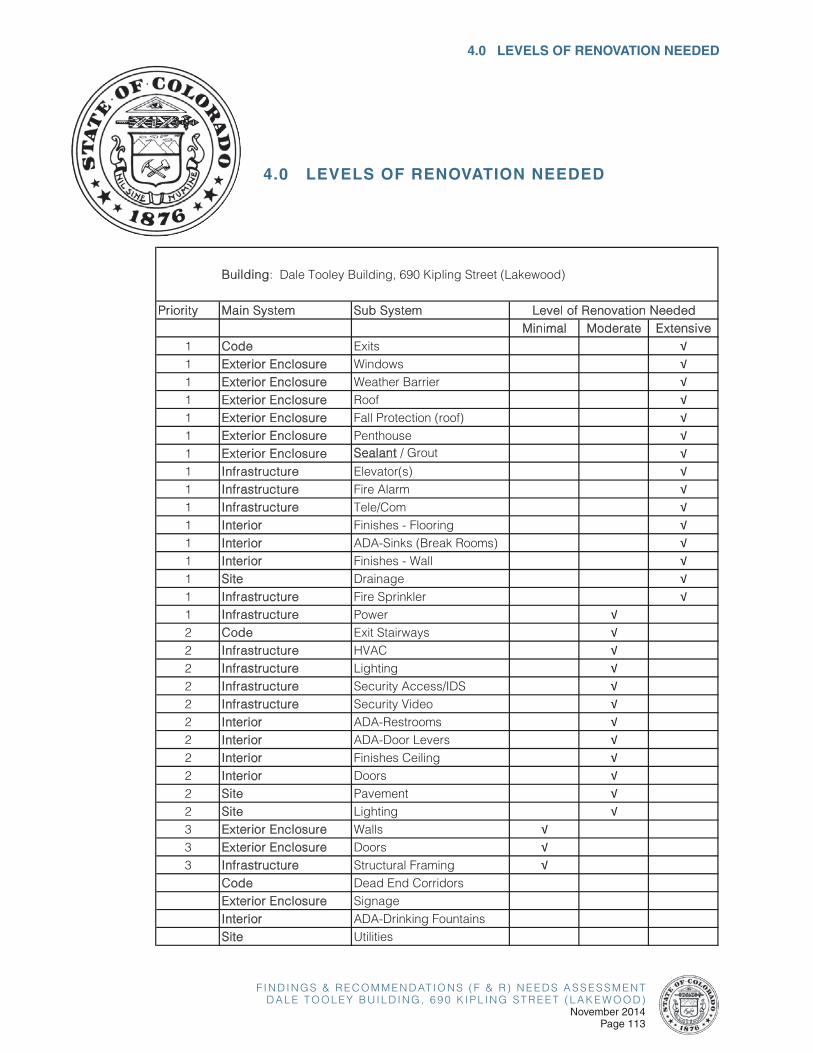
F I N D I N G S & R E C O M M E N D AT I O N S ( F & R ) N E E D S A S S E S S M E N TD A L E T O O L E Y B U I L D I N G , 6 9 0 K I P L I N G S T R E E T ( L A K E W O O D )
November 2014Page 113
4.0 LEVELS OF RENOVATION NEEDED
4.0 LEVELS OF RENOVATION NEEDED
Priority Main System Sub SystemMinimal Moderate Extensive
1 Code Exits �1 Exterior Enclosure Windows �1 Exterior Enclosure Weather Barrier �1 Exterior Enclosure Roof �1 Exterior Enclosure Fall Protection (roof) �1 Exterior Enclosure Penthouse �1 Exterior Enclosure Sealant / Grout �1 Infrastructure Elevator(s) �1 Infrastructure Fire Alarm �1 Infrastructure Tele/Com �1 Interior Finishes - Flooring �1 Interior ADA-Sinks (Break Rooms) �1 Interior Finishes - Wall �1 Site Drainage �1 Infrastructure Fire Sprinkler �1 Infrastructure Power �2 Code Exit Stairways �2 Infrastructure HVAC �2 Infrastructure Lighting �2 Infrastructure Security Access/IDS �2 Infrastructure Security Video �2 Interior ADA-Restrooms �2 Interior ADA-Door Levers �2 Interior Finishes Ceiling �2 Interior Doors �2 Site Pavement �2 Site Lighting �3 Exterior Enclosure Walls �3 Exterior Enclosure Doors �3 Infrastructure Structural Framing �
Code Dead End CorridorsExterior Enclosure Signage Interior ADA-Drinking FountainsSite Utilities
Building: Dale Tooley Building, 690 Kipling Street (Lakewood)
Level of Renovation Needed

F I N D I N G S & R E C O M M E N D AT I O N S ( F & R ) N E E D S A S S E S S M E N TD A L E T O O L E Y B U I L D I N G , 6 9 0 K I P L I N G S T R E E T ( L A K E W O O D )November 2014Page 114
This page left intentionally blank.
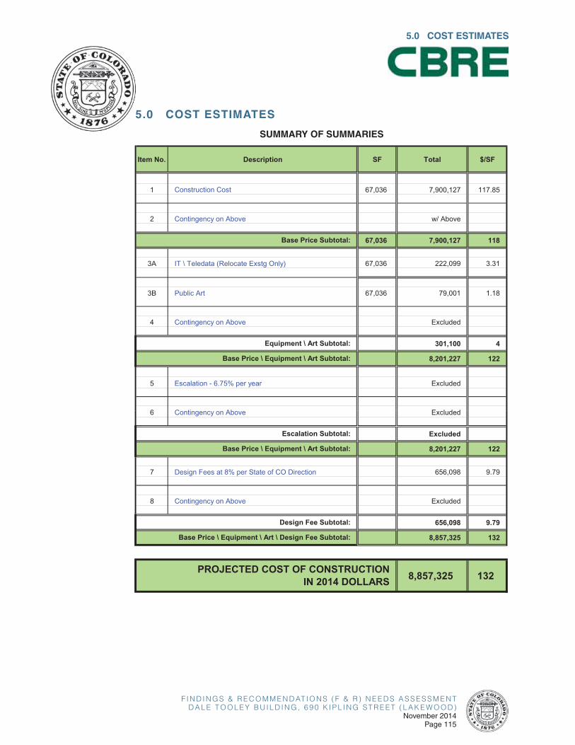
F I N D I N G S & R E C O M M E N D AT I O N S ( F & R ) N E E D S A S S E S S M E N TD A L E T O O L E Y B U I L D I N G , 6 9 0 K I P L I N G S T R E E T ( L A K E W O O D )
November 2014Page 115
5.0 COST ESTIMATES
5.0 COST ESTIMATES
SUMMARY OF SUMMARIES
Item No. Description SF Total $/SF
1 Construction Cost 67,036 7,900,127 117.85
2 Contingency on Above w/ Above
67,036 7,900,127 118
3A IT \ Teledata (Relocate Exstg Only) 67,036 222,099 3.31
3B Public Art 67,036 79,001 1.18
4 Contingency on Above Excluded
301,100 4
8,201,227 122
5 Escalation - 6.75% per year Excluded
6 C ti Ab E l d d
Base Price Subtotal:
Equipment \ Art Subtotal:
Base Price \ Equipment \ Art Subtotal:
6 Contingency on Above Excluded
Excluded
8,201,227 122
7 Design Fees at 8% per State of CO Direction 656,098 9.79
8 Contingency on Above Excluded
656,098 9.79
8,857,325 132
8,857,325 132PROJECTED COST OF CONSTRUCTIONIN 2014 DOLLARS
Escalation Subtotal:
Base Price \ Equipment \ Art Subtotal:
Design Fee Subtotal:
Base Price \ Equipment \ Art \ Design Fee Subtotal:
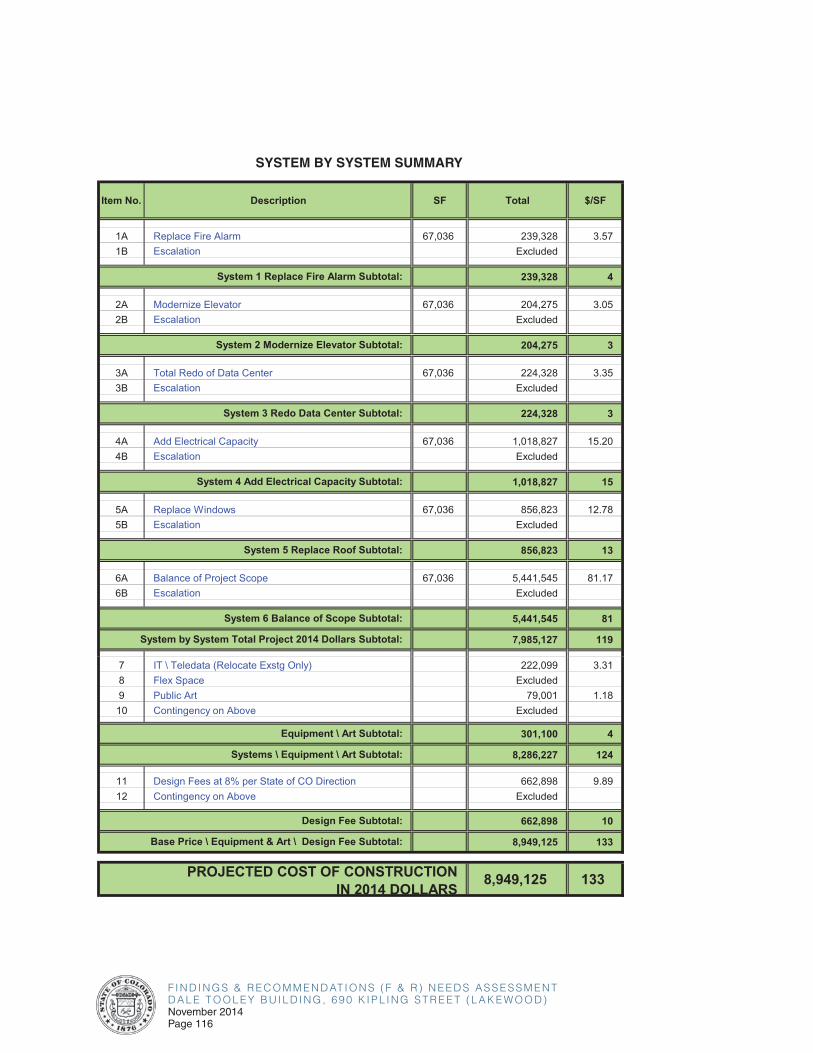
F I N D I N G S & R E C O M M E N D AT I O N S ( F & R ) N E E D S A S S E S S M E N TD A L E T O O L E Y B U I L D I N G , 6 9 0 K I P L I N G S T R E E T ( L A K E W O O D )November 2014Page 116
SYSTEM BY SYSTEM SUMMARY
Item No. Description SF Total $/SF
1A Replace Fire Alarm 67,036 239,328 3.571B Escalation Excluded
239,328 4
2A Modernize Elevator 67,036 204,275 3.052B Escalation Excluded
204,275 3
3A Total Redo of Data Center 67,036 224,328 3.353B Escalation Excluded
224,328 3
4A Add Electrical Capacity 67,036 1,018,827 15.204B Escalation Excluded
1,018,827 15
5A Replace Windows 67,036 856,823 12.785B Escalation Excluded
856,823 13
6A Balance of Project Scope 67,036 5,441,545 81.176B Escalation Excluded
5,441,545 81
7,985,127 119
System 1 Replace Fire Alarm Subtotal:
System 2 Modernize Elevator Subtotal:
System 3 Redo Data Center Subtotal:
System 4 Add Electrical Capacity Subtotal:
System 5 Replace Roof Subtotal:
System 6 Balance of Scope Subtotal:
System by System Total Project 2014 Dollars Subtotal:
7 IT \ Teledata (Relocate Exstg Only) 222,099 3.318 Flex Space Excluded9 Public Art 79,001 1.1810 Contingency on Above Excluded
301,100 4
8,286,227 124
11 Design Fees at 8% per State of CO Direction 662,898 9.8912 Contingency on Above Excluded
662,898 10
8,949,125 133
8,949,125 133
Base Price \ Equipment & Art \ Design Fee Subtotal:
Equipment \ Art Subtotal:
Systems \ Equipment \ Art Subtotal:
Design Fee Subtotal:
PROJECTED COST OF CONSTRUCTIONIN 2014 DOLLARS

F I N D I N G S & R E C O M M E N D AT I O N S ( F & R ) N E E D S A S S E S S M E N TD A L E T O O L E Y B U I L D I N G , 6 9 0 K I P L I N G S T R E E T ( L A K E W O O D )
November 2014Page 117
13 FF&E 54,911 1,372,775 25.0014 Move Management 67,036 81,159 1.2115 Escalation Excluded16 Contingency on Above Excluded
1,453,934
1,453,934 21.69
ADD ALTERNATE
Move Management Subtotal:
Add Alternate Subtotal:
5.0 COST ESTIMATES

F I N D I N G S & R E C O M M E N D AT I O N S ( F & R ) N E E D S A S S E S S M E N TD A L E T O O L E Y B U I L D I N G , 6 9 0 K I P L I N G S T R E E T ( L A K E W O O D )November 2014Page 118
FF&E DETAILED ESTIMATE - BASE
Amount CSI Sec. Total
01 50 00 Temporary Facilities and Controls Excluded
Flex Space for Multiple Moves and\or Tenant Holdover Excluded Per Owner
General Condtions & General Requirements Subtotal Excluded
11 90 00 Owner Furnished Equipment Excluded
11 99 00 A\V & IT Equipment 137,104
AV / IT @ Large Conference Rooms 5 EA 5,230.00 26,150
VOIP Telephone System 317 EA 280.00 88,800
New PC Computer Workstations 27 EA 810.00 22,154
State of CO Servers, Routers, Wireless Access and IT Equipment not w/Above Excluded
Equipment Subtotal 137,104
12 99 00 Furnishings 1,372,775
New Employee Workstations 54,911 SF 25.00 1,372,775
Minor Repair to Existing Employee Workstations EA 160.00 Excluded
Furnishings @ Large Conference Rooms EA 4,150.00 Excluded
Furnishings @ Medium Conference Rooms EA 2,905.00 Excluded
Furnishings @ Small Conference Rooms EA 1,260.00 Excluded
12 99 99 Art 79,001
Art in Public Places @ 1.0% of Construction Cost 1 LS 79,001.27 79,001
Furnishings Subtotal 1,451,776
13 49 00 Radiation Protection Excluded
Special Construction Subtotal Excluded
27 10 00 Structured Cabling 84,995
Teledata Cabling System Conduit & Wire Upgrades w/Const Cost
Teledata Cabling Terminations, Testing & Tone-Out 317 EA 268.00 84,995
27 41 00 Audio-Visual Systems Excluded
27 53 00 Distributed Systems Excluded
Communications Subtotal 84,995
34 99 99 Move Management 81,159
Moving Labor, Material, Equipment & Supervision 268 EA 243.00 65,159
Relocate Existing PC Computer Workstations 246 EA 65.00 16,000
Transportation Subtotal 81,159
Total FF&E, IT, & Move Management 3,510,069
CommentsQuantityTotal ProjectCSI
Section Description Unit Unit Cost

F I N D I N G S & R E C O M M E N D AT I O N S ( F & R ) N E E D S A S S E S S M E N TD A L E T O O L E Y B U I L D I N G , 6 9 0 K I P L I N G S T R E E T ( L A K E W O O D )
November 2014Page 119
DETAILED ESTIMATE - SUMMARY
5.0 COST ESTIMATES
67,036
$/GSF Section Totals
Total w/Burdens
02 Existing Conditions 1.89 126,650 175,749.35 03 Concrete 0.46 31,142 43,215.36 04 Masonry 5.56 372,842 517,384.68 05 Metals 4.23 283,693 393,674.99 06 Woods & Plastics 4.32 289,870 402,247.34 07 Thermal & Moisture 1.36 91,338 126,747.41 08 Doors & Glazing 11.21 751,204 1,042,430.3309 Finishes 21.97 1,472,809 2,043,787.3910 Specialties 1.18 79,146 109,829.15 11 Equipment 0.79 53,012 73,563.49 12 Furnishings 1.17 78,133 108,423.54 13 Special Construction Excluded14 Conveying Systems 2.09 140,000 194,275.15 21 Fire Supression 0.18 11,765 16,325.80 22 Plumbing 1.04 69,463 96,391.98 23 HVAC 10.93 732,841 1,016,949.0826 Electrical 10.68 716,179 993,827.15 27 Communications 2.30 154,451 214,328.43 28 Security w/2600031 Earthwork Excluded32 Exterior Improvements 3.56 238,510 330,976.10 33 Utilities Excluded34 Transportation Excluded
SUBTOTAL: CONSTRUCTION COST DETAIL 84.93 5,693,048 7,900,126.72
General Conditions (GC's Onsite Overhead) 9.80% 557,919 Materials Testing 0.10% 6,251 Design & Preconstruction Contingency 10.00% 625,722 Owner's Construction Contingency (after NTP) 5.00% 344,147 Permits 1.90% 137,315
SUBTOTAL: DIRECT CONSTRUCTION COSTS 109.86 7,364,401
General\Professional Liability Insurance 0.90% 66,280 Builder's Risk Insurance 1.50% 111,460 Performance & Payment Bond 1.10% 82,964 Bid Bond 0.20% 15,250 Tap Fees & Other Owner Soft Costs ExcludedGC's Offsite Overhead & Profit (Fee) 3.40% 259,772 Escalation\Year (to Mid-Point of Construction) 6.75%oject Summary
SUBTOTAL: DIRECT & INDIRECT CONSTRUCTION COSTS 117.85 7,900,127
Project GSFCSI
Division Description
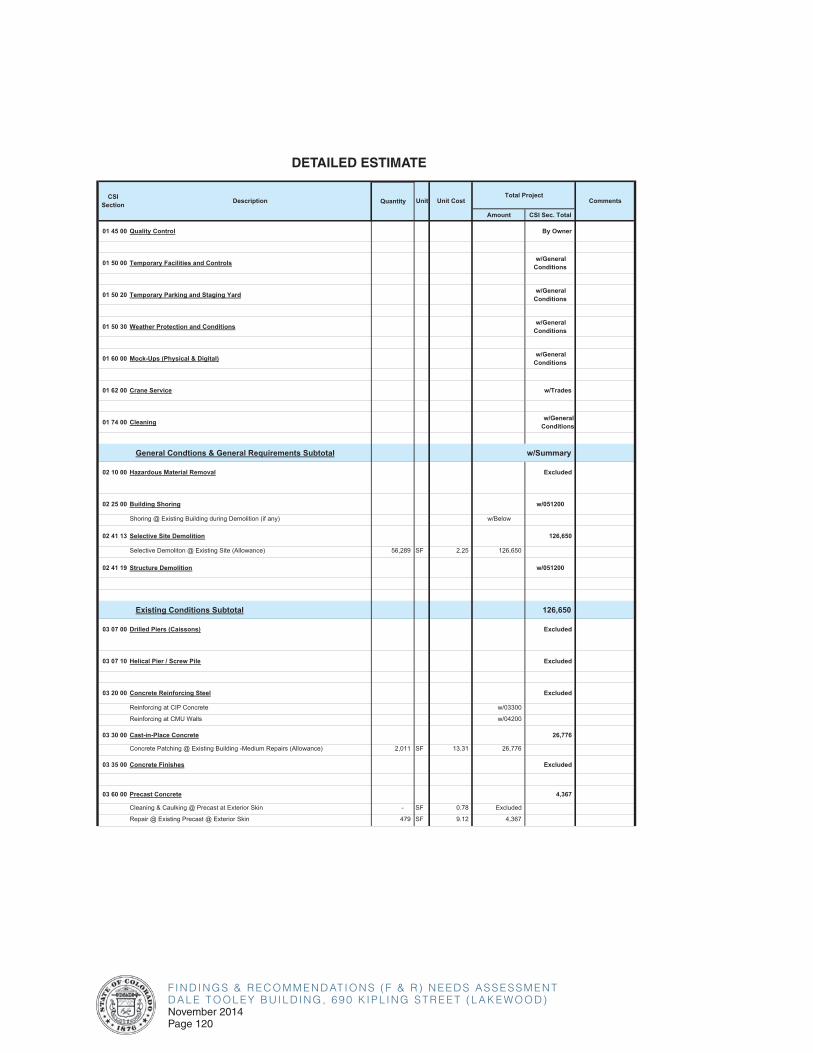
F I N D I N G S & R E C O M M E N D AT I O N S ( F & R ) N E E D S A S S E S S M E N TD A L E T O O L E Y B U I L D I N G , 6 9 0 K I P L I N G S T R E E T ( L A K E W O O D )November 2014Page 120
DETAILED ESTIMATE
Amount CSI Sec. Total
01 45 00 Quality Control By Owner
01 50 00 Temporary Facilities and Controls w/General Conditions
01 50 20 Temporary Parking and Staging Yard w/General Conditions
01 50 30 Weather Protection and Conditions w/General Conditions
01 60 00 Mock-Ups (Physical & Digital) w/General Conditions
01 62 00 Crane Service w/Trades
01 74 00 Cleaning w/GeneralConditions
General Condtions & General Requirements Subtotal w/Summary
02 10 00 Hazardous Material Removal Excluded
02 25 00 Building Shoring w/051200
Shoring @ Existing Building during Demolition (if any) w/Below
02 41 13 Selective Site Demolition 126,650
Selective Demoliton @ Existing Site (Allowance) 56,289 SF 2.25 126,650
02 41 19 Structure Demolition w/051200
Existing Conditions Subtotal 126,650
03 07 00 Drilled Piers (Caissons) Excluded
03 07 10 Helical Pier / Screw Pile Excluded
03 20 00 Concrete Reinforcing Steel Excluded
Reinforcing at CIP Concrete w/03300
Reinforcing at CMU Walls w/04200
03 30 00 Cast-in-Place Concrete 26,776
Concrete Patching @ Existing Building -Medium Repairs (Allowance) 2,011 SF 13.31 26,776
03 35 00 Concrete Finishes Excluded
03 60 00 Precast Concrete 4,367
Cleaning & Caulking @ Precast at Exterior Skin - SF 0.78 Excluded
Repair @ Existing Precast @ Exterior Skin 479 SF 9.12 4,367
CSISection Description Unit Unit Cost CommentsQuantity
Total Project
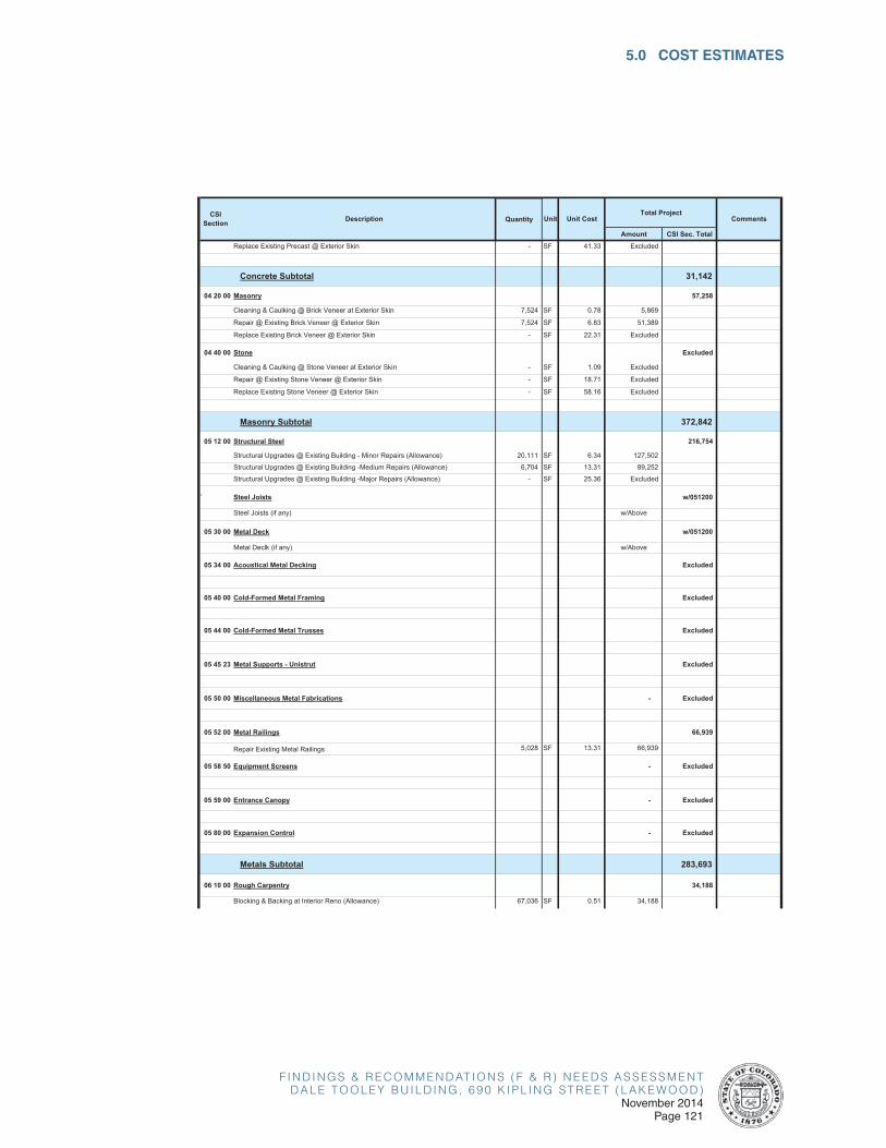
F I N D I N G S & R E C O M M E N D AT I O N S ( F & R ) N E E D S A S S E S S M E N TD A L E T O O L E Y B U I L D I N G , 6 9 0 K I P L I N G S T R E E T ( L A K E W O O D )
November 2014Page 121
5.0 COST ESTIMATES
Amount CSI Sec. Total
CSISection Description Unit Unit Cost CommentsQuantity
Total Project
Replace Existing Precast @ Exterior Skin - SF 41.33 Excluded
Concrete Subtotal 31,142
04 20 00 Masonry 57,258
Cleaning & Caulking @ Brick Veneer at Exterior Skin 7,524 SF 0.78 5,869
Repair @ Existing Brick Veneer @ Exterior Skin 7,524 SF 6.83 51,389
Replace Existing Brick Veneer @ Exterior Skin - SF 22.31 Excluded
04 40 00 Stone Excluded
Cleaning & Caulking @ Stone Veneer at Exterior Skin - SF 1.09 Excluded
Repair @ Existing Stone Veneer @ Exterior Skin - SF 18.71 Excluded
Replace Existing Stone Veneer @ Exterior Skin - SF 58.16 Excluded
Masonry Subtotal 372,842
05 12 00 Structural Steel 216,754
Structural Upgrades @ Existing Building - Minor Repairs (Allowance) 20,111 SF 6.34 127,502
Structural Upgrades @ Existing Building -Medium Repairs (Allowance) 6,704 SF 13.31 89,252
Structural Upgrades @ Existing Building -Major Repairs (Allowance) - SF 25.36 Excluded
` Steel Joists w/051200
Steel Joists (if any) w/Above
05 30 00 Metal Deck w/051200
Metal Declk (if any) w/Above
05 34 00 Acoustical Metal Decking Excluded
05 40 00 Cold-Formed Metal Framing Excluded
05 44 00 Cold-Formed Metal Trusses Excluded
05 45 23 Metal Supports - Unistrut Excluded
05 50 00 Miscellaneous Metal Fabrications - Excluded
05 52 00 Metal Railings 66,939
Repair Existing Metal Railings 5,028 SF 13.31 66,939
05 58 50 Equipment Screens - Excluded
05 59 00 Entrance Canopy - Excluded
05 80 00 Expansion Control - Excluded
Metals Subtotal 283,693
06 10 00 Rough Carpentry 34,188
Blocking & Backing at Interior Reno (Allowance) 67,036 SF 0.51 34,188
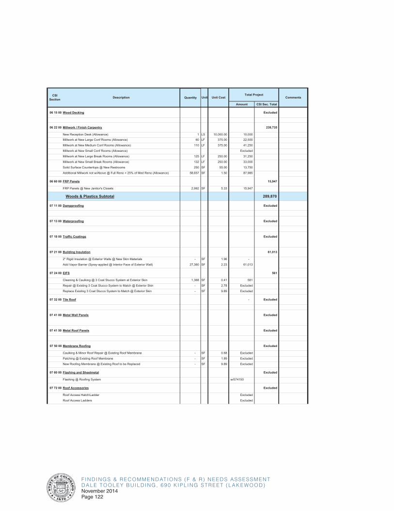
F I N D I N G S & R E C O M M E N D AT I O N S ( F & R ) N E E D S A S S E S S M E N TD A L E T O O L E Y B U I L D I N G , 6 9 0 K I P L I N G S T R E E T ( L A K E W O O D )November 2014Page 122
Amount CSI Sec. Total
CSISection Description Unit Unit Cost CommentsQuantity
Total Project
06 15 00 Wood Decking Excluded
06 22 00 Millwork / Finish Carpentry 239,735
New Reception Desk (Allowance) 1 LS 10,000.00 10,000
Millwork at New Large Conf Rooms (Allowance) 60 LF 375.00 22,500
Millwork at New Medium Conf Rooms (Allowance) 110 LF 375.00 41,250
Millwork at New Small Conf Rooms (Allowance) Excluded
Millwork at New Large Break Rooms (Allowance) 125 LF 250.00 31,250
Millwork at New Small Break Rooms (Allowance) 132 LF 250.00 33,000
Solid Surface Countertops @ New Restrooms 250 SF 55.00 13,750
Additional Millwork not w/Above @ Full Reno + 25% of Med Reno (Allowance) 58,657 SF 1.50 87,985
06 60 00 FRP Panels 15,947
FRP Panels @ New Janitor's Closets 2,992 SF 5.33 15,947
Woods & Plastics Subtotal 289,870
07 11 00 Dampproofing Excluded
07 13 00 Waterproofing Excluded
07 18 00 Traffic Coatings Excluded
07 21 00 Building Insulation 61,013
2" Rigid Insulation @ Exterior Walls @ New Skin Materials - SF 1.96 -
Add Vapor Barrier (Spray-applied @ Interior Face of Exterior Wall) 27,360 SF 2.23 61,013
07 24 00 EIFS 561
Cleaning & Caulking @ 3 Coat Stucco System at Exterior Skin 1,368 SF 0.41 561
Repair @ Existing 3 Coat Stucco System to Match @ Exterior Skin - SF 2.78 Excluded
Replace Existing 3 Coat Stucco System to Match @ Exterior Skin - SF 9.89 Excluded
07 32 00 Tile Roof - Excluded
07 41 00 Metal Wall Panels Excluded
07 41 50 Metal Roof Panels Excluded
07 50 00 Membrane Roofing Excluded
Caulking & Minor Roof Repair @ Existing Roof Membrane - SF 0.68 Excluded
Patching @ Existing Roof Membrane - SF 1.89 Excluded
New Roofing Membrane @ Existing Roof to be Replaced - SF 9.89 Excluded
07 60 00 Flashing and Sheetmetal Excluded
Flashing @ Roofing System w/074150
07 72 00 Roof Accessories Excluded
Roof Access Hatch\Ladder Excluded
Roof Access Ladders Excluded
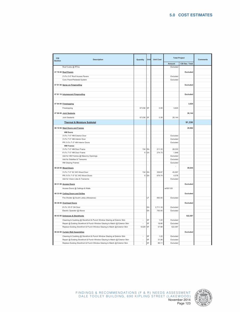
F I N D I N G S & R E C O M M E N D AT I O N S ( F & R ) N E E D S A S S E S S M E N TD A L E T O O L E Y B U I L D I N G , 6 9 0 K I P L I N G S T R E E T ( L A K E W O O D )
November 2014Page 123
5.0 COST ESTIMATES
Amount CSI Sec. Total
CSISection Description Unit Unit Cost CommentsQuantity
Total Project
Roof Curbs @ RTUs Excluded
07 76 00 Roof Pavers Excluded
2'-0"x 2'-0" Roof Access Pavers Excluded
Conc Paver\Pedestal System Excluded
07 81 00 Spray on Fireproofing Excluded
07 81 10 Intumescent Fireproofing Excluded
07 84 00 Firestopping 3,620
Firestopping 67,036 SF 0.05 3,620
07 90 00 Joint Sealants 26,144
Joint Sealants 67,036 SF 0.39 26,144
Thermal & Moisture Subtotal 91,338
08 10 00 Steel Doors and Frames 29,982
HM Doors
3'-0"x 7'-0" HM Exterior Door Excluded
3'-0"x 7'-0" HM Interior Door Excluded
PR 3'-0"x 7'-0" HM Interior Doors Excluded
HM Frames
3'-0"x 7'-0" HM Door Frame 134 EA 211.33 28,333
6'-0"x 7'-0" HM Door Frame 6 EA 274.73 1,648
Add for HM Frames @ Masonry Openings Excluded
Add for Sidelites & Transoms Excluded
HM Glazing Frames Excluded
08 20 00 Wood Doors-
49,645
3'-0"x 7'-0" SC WO Wood Door 134 EA 339.87 45,567
PR 3'-0"x 7'-0" SC WO Wood Doors 6 EA 679.74 4,078
Add for Vision Lites & Transoms Excluded
08 31 00 Access Doors Excluded
Access Doors @ Ceilings & Walls w/091120
08 33 00 Coiling Doors and Grilles Excluded
Fire Shutter @ South Lobby (Allowance) LF 950.00 Excluded
08 36 00 Overhead Doors Excluded
8'-0"x 10'-0" OH Door EA 2,711.16 Excluded
Electric Operator @ Above EA 700.00 Excluded
08 43 00 Entrances & Storefronts 522,587
Cleaning & Caulking @ Storefront & Punch Window Glazing at Exterior Skin - SF 1.22 Excluded
Repair @ Existing Storefront & Punch Window Glazing to Match @ Exterior Skin - SF 18.66 Excluded
Replace Existing Storefront & Punch Window Glazing to Match @ Exterior Skin 9,029 SF 57.88 522,587
08 44 00 Curtain Wall Assemblies Excluded
Cleaning & Caulking @ Storefront & Punch Window Glazing at Exterior Skin - SF 1.22 Excluded
Repair @ Existing Storefront & Punch Window Glazing to Match @ Exterior Skin - SF 31.06 Excluded
Replace Existing Storefront & Punch Window Glazing to Match @ Exterior Skin - SF 89.11 Excluded
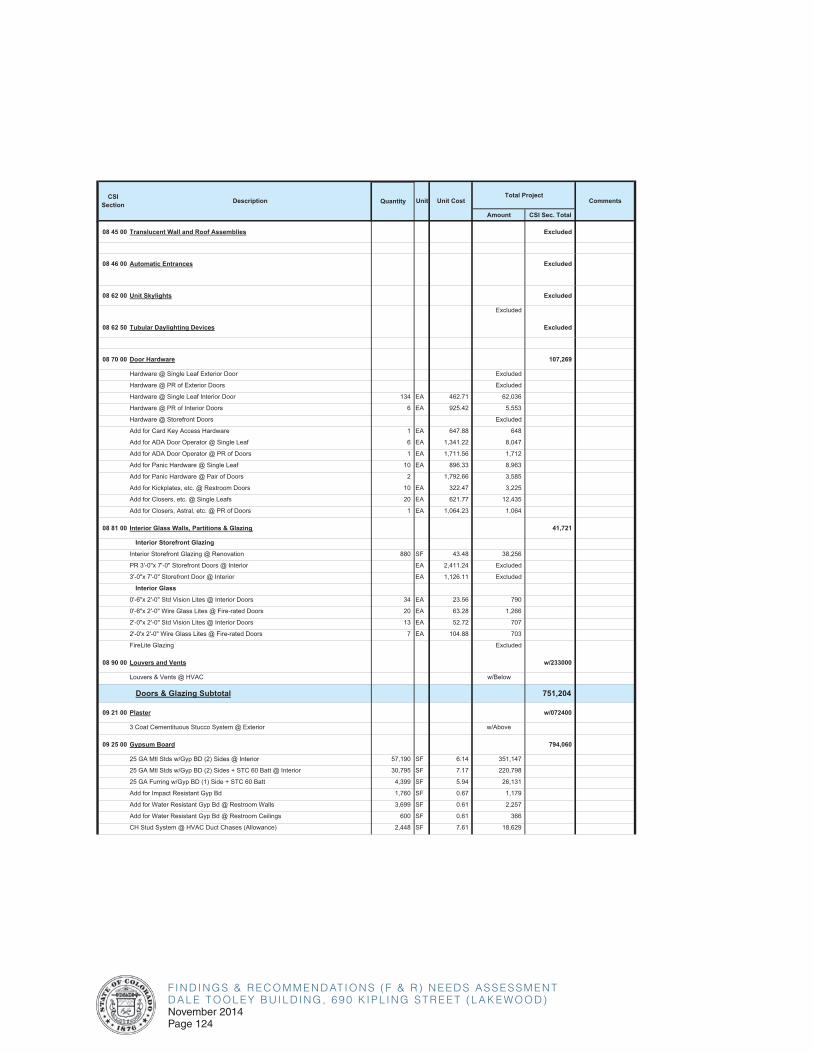
F I N D I N G S & R E C O M M E N D AT I O N S ( F & R ) N E E D S A S S E S S M E N TD A L E T O O L E Y B U I L D I N G , 6 9 0 K I P L I N G S T R E E T ( L A K E W O O D )November 2014Page 124
Amount CSI Sec. Total
CSISection Description Unit Unit Cost CommentsQuantity
Total Project
08 45 00 Translucent Wall and Roof Assemblies Excluded
08 46 00 Automatic Entrances Excluded
08 62 00 Unit Skylights Excluded
Excluded
08 62 50 Tubular Daylighting Devices Excluded
08 70 00 Door Hardware 107,269
Hardware @ Single Leaf Exterior Door Excluded
Hardware @ PR of Exterior Doors Excluded
Hardware @ Single Leaf Interior Door 134 EA 462.71 62,036
Hardware @ PR of Interior Doors 6 EA 925.42 5,553
Hardware @ Storefront Doors Excluded
Add for Card Key Access Hardware 1 EA 647.88 648
Add for ADA Door Operator @ Single Leaf 6 EA 1,341.22 8,047
Add for ADA Door Operator @ PR of Doors 1 EA 1,711.56 1,712
Add for Panic Hardware @ Single Leaf 10 EA 896.33 8,963
Add for Panic Hardware @ Pair of Doors 2 1,792.66 3,585
Add for Kickplates, etc. @ Restroom Doors 10 EA 322.47 3,225
Add for Closers, etc. @ Single Leafs 20 EA 621.77 12,435
Add for Closers, Astral, etc. @ PR of Doors 1 EA 1,064.23 1,064
08 81 00 Interior Glass Walls, Partitions & Glazing 41,721
Interior Storefront Glazing
Interior Storefront Glazing @ Renovation 880 SF 43.48 38,256
PR 3'-0"x 7'-0" Storefront Doors @ Interior EA 2,411.24 Excluded
3'-0"x 7'-0" Storefront Door @ Interior EA 1,126.11 Excluded
Interior Glass
0'-6"x 2'-0" Std Vision Lites @ Interior Doors 34 EA 23.56 790
0'-6"x 2'-0" Wire Glass Lites @ Fire-rated Doors 20 EA 63.28 1,266
2'-0"x 2'-0" Std Vision Lites @ Interior Doors 13 EA 52.72 707
2'-0'x 2'-0" Wire Glass Lites @ Fire-rated Doors 7 EA 104.88 703
FireLite Glazing Excluded
08 90 00 Louvers and Vents w/233000
Louvers & Vents @ HVAC w/Below
Doors & Glazing Subtotal 751,204
09 21 00 Plaster w/072400
3 Coat Cementituous Stucco System @ Exterior w/Above
09 25 00 Gypsum Board 794,060
25 GA Mtl Stds w/Gyp BD (2) Sides @ Interior 57,190 SF 6.14 351,147
25 GA Mtl Stds w/Gyp BD (2) Sides + STC 60 Batt @ Interior 30,795 SF 7.17 220,798
25 GA Furring w/Gyp BD (1) Side + STC 60 Batt 4,399 SF 5.94 26,131
Add for Impact Resistant Gyp Bd 1,760 SF 0.67 1,179
Add for Water Resistant Gyp Bd @ Restroom Walls 3,699 SF 0.61 2,257
Add for Water Resistant Gyp Bd @ Restroom Ceilings 600 SF 0.61 366
CH Stud System @ HVAC Duct Chases (Allowance) 2,448 SF 7.61 18,629
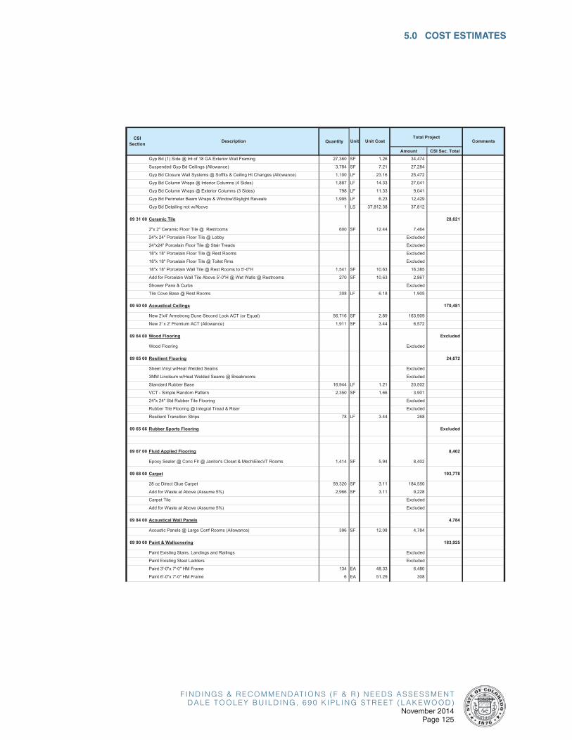
F I N D I N G S & R E C O M M E N D AT I O N S ( F & R ) N E E D S A S S E S S M E N TD A L E T O O L E Y B U I L D I N G , 6 9 0 K I P L I N G S T R E E T ( L A K E W O O D )
November 2014Page 125
5.0 COST ESTIMATES
Amount CSI Sec. Total
CSISection Description Unit Unit Cost CommentsQuantity
Total Project
Gyp Bd (1) Side @ Int of 18 GA Exterior Wall Framing 27,360 SF 1.26 34,474
Suspended Gyp Bd Ceilings (Allowance) 3,784 SF 7.21 27,284
Gyp Bd Closure Wall Systems @ Soffits & Ceiling Ht Changes (Allowance) 1,100 LF 23.16 25,472
Gyp Bd Column Wraps @ Interior Columns (4 Sides) 1,887 LF 14.33 27,041
Gyp Bd Column Wraps @ Exterior Columns (3 Sides) 798 LF 11.33 9,041
Gyp Bd Perimeter Beam Wraps & Window\Skylight Reveals 1,995 LF 6.23 12,429
Gyp Bd Detailing not w/Above 1 LS 37,812.38 37,812
09 31 00 Ceramic Tile 28,621
2"x 2" Ceramic Floor Tile @ Restrooms 600 SF 12.44 7,464
24"x 24" Porcelain Floor Tile @ Lobby Excluded
24"x24" Porcelain Floor Tile @ Stair Treads Excluded
18"x 18" Porcelain Floor Tile @ Rest Rooms Excluded
18"x 18" Porcelain Floor Tile @ Toilet Rms Excluded
18"x 18" Porcelain Wall Tile @ Rest Rooms to 5'-0"H 1,541 SF 10.63 16,385
Add for Porcelain Wall Tile Above 5'-0"H @ Wet Walls @ Restrooms 270 SF 10.63 2,867
Shower Pans & Curbs Excluded
Tile Cove Base @ Rest Rooms 308 LF 6.18 1,905
09 50 00 Acoustical Ceilings 170,481
New 2'x4' Armstrong Dune Second Look ACT (or Equal) 56,716 SF 2.89 163,909
New 2' x 2' Premium ACT (Allowance) 1,911 SF 3.44 6,572
09 64 00 Wood Flooring Excluded
Wood Flooring Excluded
09 65 00 Resilient Flooring 24,672
Sheet Vinyl w/Heat Welded Seams Excluded
3MM Linoleum w/Heat Welded Seams @ Breakrooms Excluded
Standard Rubber Base 16,944 LF 1.21 20,502
VCT - Simple Random Pattern 2,350 SF 1.66 3,901
24"x 24" Std Rubber Tile Flooring Excluded
Rubber Tile Flooring @ Integral Tread & Riser Excluded
Resilient Transition Strips 78 LF 3.44 268
09 65 66 Rubber Sports Flooring Excluded
09 67 00 Fluid Applied Flooring 8,402
Epoxy Sealer @ Conc Flr @ Janitor's Closet & Mech\Elec\IT Rooms 1,414 SF 5.94 8,402
09 68 00 Carpet 193,778
28 oz Direct Glue Carpet 59,320 SF 3.11 184,550
Add for Waste at Above (Assume 5%) 2,966 SF 3.11 9,228
Carpet Tile Excluded
Add for Waste at Above (Assume 5%) Excluded
09 84 00 Acoustical Wall Panels 4,784
Acoustic Panels @ Large Conf Rooms (Allowance) 396 SF 12.08 4,784
09 90 00 Paint & Wallcovering 183,925
Paint Existing Stairs, Landings and Railings Excluded
Paint Existing Steel Ladders Excluded
Paint 3'-0"x 7'-0" HM Frame 134 EA 48.33 6,480
Paint 6'-0"x 7'-0" HM Frame 6 EA 51.29 308
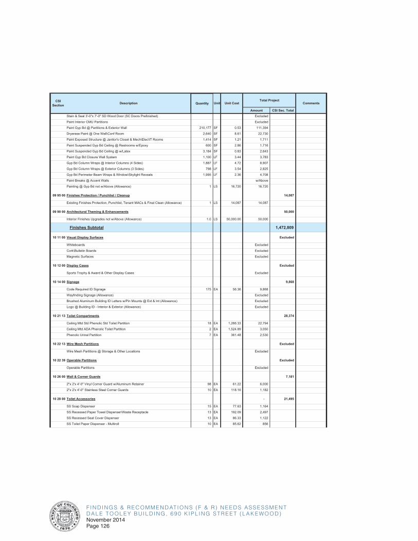
F I N D I N G S & R E C O M M E N D AT I O N S ( F & R ) N E E D S A S S E S S M E N TD A L E T O O L E Y B U I L D I N G , 6 9 0 K I P L I N G S T R E E T ( L A K E W O O D )November 2014Page 126
Amount CSI Sec. Total
CSISection Description Unit Unit Cost CommentsQuantity
Total Project
Stain & Seal 3'-0"x 7'-0" SD Wood Door (SC Doors Prefinished) Excluded
Paint Interior CMU Partitions Excluded
Paint Gyp Bd @ Partitions & Exterior Wall 210,177 SF 0.53 111,394
Dryerase Paint @ One Wall\Conf Room 2,640 SF 8.61 22,730
Paint Exposed Structure @ Janitor's Closet & Mech\Elec\IT Rooms 1,414 SF 1.21 1,711
Paint Suspended Gyp Bd Ceiling @ Restrooms w/Epoxy 600 SF 2.86 1,716
Paint Suspended Gyp Bd Ceiling @ w/Latex 3,184 SF 0.83 2,643
Paint Gyp Bd Closure Wall System 1,100 LF 3.44 3,783
Gyp Bd Column Wraps @ Interior Columns (4 Sides) 1,887 LF 4.72 8,907
Gyp Bd Column Wraps @ Exterior Columns (3 Sides) 798 LF 3.54 2,825
Gyp Bd Perimeter Beam Wraps & Window\Skylight Reveals 1,995 LF 2.36 4,708
Paint Breaks @ Accent Walls w/Above
Painting @ Gyp Bd not w/Above (Allowance) 1 LS 16,720 16,720
09 95 00 Finishes Protection / Punchlist / Cleanup 14,087
Existing Finishes Protection, Punchlist, Tenant MACs & Final Clean (Allowance) 1 LS 14,087 14,087
09 90 00 Architectural Theming & Enhancements 50,000
Interior Finishes Upgrades not w/Above (Allowance) 1.0 LS 50,000.00 50,000
Finishes Subtotal 1,472,809
10 11 00 Visual Display Surfaces Excluded
Whiteboards Excluded
Cork\Bulletin Boards Excluded
Magnetic Surfaces Excluded
10 12 00 Display Cases Excluded
Sports Trophy & Award & Other Display Cases Excluded
10 14 00 Signage 9,868
Code Required ID Signage 175 EA 56.36 9,868
Wayfinding Signage (Allowance) Excluded
Brushed Aluminum Building ID Letters w/Pin Mounts @ Ext & Int (Allowance) Excluded
Logo @ Building ID - Interior & Exterior (Allowance) Excluded
10 21 13 Toilet Compartments 28,374
Ceiling Mtd Std Phenolic Std Toilet Partition 18 EA 1,266.33 22,794
Ceiling Mtd ADA Phenolic Toilet Partition 2 EA 1,524.89 3,050
Phenolic Urinal Partition 7 EA 361.48 2,530
10 22 13 Wire Mesh Partitions Excluded
Wire Mesh Partitions @ Storage & Other Locations Excluded
10 22 39 Operable Partitions Excluded
Operable Partitions Excluded
10 26 00 Wall & Corner Guards 7,181
2"x 2'x 4'-0" Vinyl Corner Guard w/Aluminum Retainer 98 EA 61.22 6,000
2"x 2'x 4'-0" Stainless Steel Corner Guards 10 EA 118.16 1,182
10 28 00 Toilet Accessories - 21,495
SS Soap Dispenser 15 EA 77.63 1,164
SS Recessed Paper Towel Dispenser\Waste Receptacle 13 EA 192.09 2,497
SS Recessed Seat Cover Dispenser 13 EA 86.33 1,122
SS Toilet Paper Dispenser - Multiroll 10 EA 85.62 856
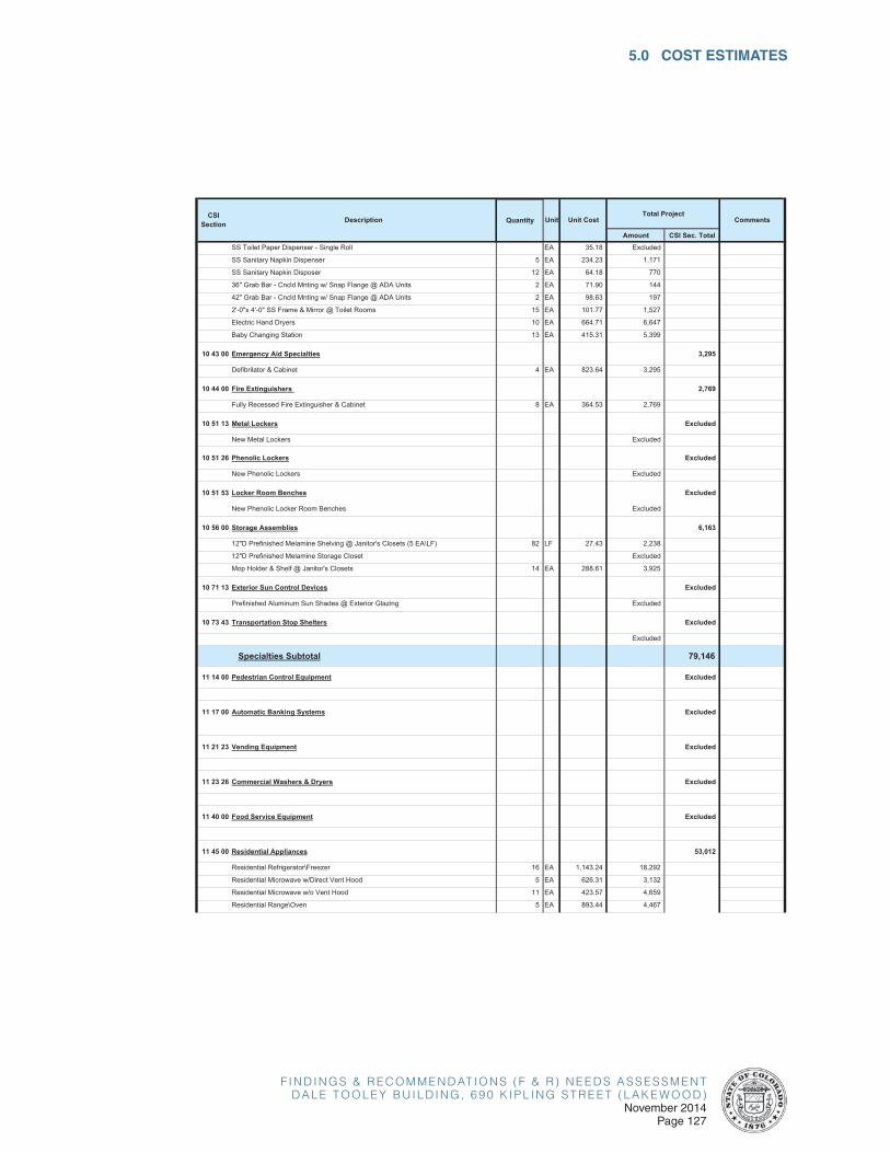
F I N D I N G S & R E C O M M E N D AT I O N S ( F & R ) N E E D S A S S E S S M E N TD A L E T O O L E Y B U I L D I N G , 6 9 0 K I P L I N G S T R E E T ( L A K E W O O D )
November 2014Page 127
5.0 COST ESTIMATES
Amount CSI Sec. Total
CSISection Description Unit Unit Cost CommentsQuantity
Total Project
SS Toilet Paper Dispenser - Single Roll EA 35.18 Excluded
SS Sanitary Napkin Dispenser 5 EA 234.23 1,171
SS Sanitary Napkin Disposer 12 EA 64.18 770
36" Grab Bar - Cncld Mnting w/ Snap Flange @ ADA Units 2 EA 71.90 144
42" Grab Bar - Cncld Mnting w/ Snap Flange @ ADA Units 2 EA 98.63 197
2'-0"x 4'-0" SS Frame & Mirror @ Toilet Rooms 15 EA 101.77 1,527
Electric Hand Dryers 10 EA 664.71 6,647
Baby Changing Station 13 EA 415.31 5,399
10 43 00 Emergency Aid Specialties 3,295
Defibrilator & Cabinet 4 EA 823.64 3,295
10 44 00 Fire Extinguishers 2,769
Fully Recessed Fire Extinguisher & Cabinet 8 EA 364.53 2,769
10 51 13 Metal Lockers Excluded
New Metal Lockers Excluded
10 51 26 Phenolic Lockers Excluded
New Phenolic Lockers Excluded
10 51 53 Locker Room Benches Excluded
New Phenolic Locker Room Benches Excluded
10 56 00 Storage Assemblies 6,163
12"D Prefinished Melamine Shelving @ Janitor's Closets (5 EA\LF) 82 LF 27.43 2,238
12"D Prefinished Melamine Storage Closet Excluded
Mop Holder & Shelf @ Janitor's Closets 14 EA 288.61 3,925
10 71 13 Exterior Sun Control Devices Excluded
Prefinished Aluminum Sun Shades @ Exterior Glazing Excluded
10 73 43 Transportation Stop Shelters Excluded
Excluded
Specialties Subtotal 79,146
11 14 00 Pedestrian Control Equipment Excluded
11 17 00 Automatic Banking Systems Excluded
11 21 23 Vending Equipment Excluded
11 23 26 Commercial Washers & Dryers Excluded
11 40 00 Food Service Equipment Excluded
11 45 00 Residential Appliances 53,012
Residential Refrigerator\Freezer 16 EA 1,143.24 18,292
Residential Microwave w/Direct Vent Hood 5 EA 626.31 3,132
Residential Microwave w/o Vent Hood 11 EA 423.57 4,659
Residential Range\Oven 5 EA 893.44 4,467
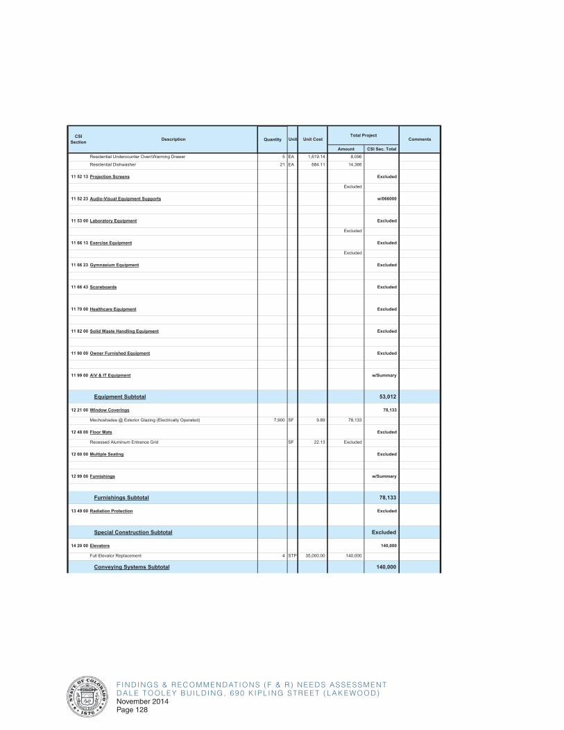
F I N D I N G S & R E C O M M E N D AT I O N S ( F & R ) N E E D S A S S E S S M E N TD A L E T O O L E Y B U I L D I N G , 6 9 0 K I P L I N G S T R E E T ( L A K E W O O D )November 2014Page 128
Amount CSI Sec. Total
CSISection Description Unit Unit Cost CommentsQuantity
Total Project
Residential Undercounter Oven\Warming Drawer 5 EA 1,619.14 8,096
Residential Dishwasher 21 EA 684.11 14,366
11 52 13 Projection Screens Excluded
Excluded
11 52 23 Audio-Visual Equipment Supports w/066000
11 53 00 Laboratory Equipment Excluded
Excluded
11 66 13 Exercise Equipment Excluded
Excluded
11 66 23 Gymnasium Equipment Excluded
11 66 43 Scoreboards Excluded
11 70 00 Healthcare Equipment Excluded
11 82 00 Solid Waste Handling Equipment Excluded
11 90 00 Owner Furnished Equipment Excluded
11 99 00 A\V & IT Equipment w/Summary
Equipment Subtotal 53,012
12 21 00 Window Coverings 78,133
Mechoshades @ Exterior Glazing (Electrically Operated) 7,900 SF 9.89 78,133
12 48 00 Floor Mats Excluded
Recessed Aluminum Entrance Grid SF 22.13 Excluded
12 60 00 Multiple Seating Excluded
12 99 00 Furnishings w/Summary
Furnishings Subtotal 78,133
13 49 00 Radiation Protection Excluded
Special Construction Subtotal Excluded
14 20 00 Elevators 140,000
Full Elevator Replacement 4 STP 35,000.00 140,000
Conveying Systems Subtotal 140,000
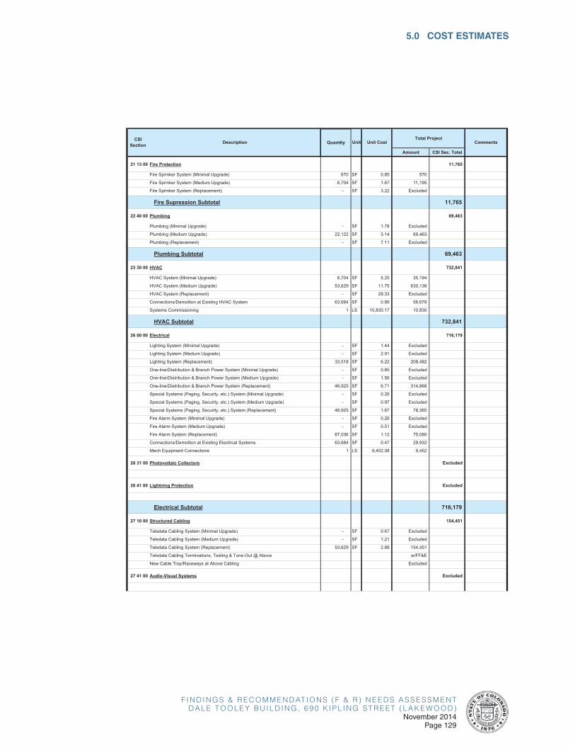
F I N D I N G S & R E C O M M E N D AT I O N S ( F & R ) N E E D S A S S E S S M E N TD A L E T O O L E Y B U I L D I N G , 6 9 0 K I P L I N G S T R E E T ( L A K E W O O D )
November 2014Page 129
5.0 COST ESTIMATES
Amount CSI Sec. Total
CSISection Description Unit Unit Cost CommentsQuantity
Total Project
21 13 00 Fire Protection 11,765
Fire Sprinker System (Minimal Upgrade) 670 SF 0.85 570
Fire Sprinker System (Medium Upgrade) 6,704 SF 1.67 11,195
Fire Sprinker System (Replacement) - SF 3.22 Excluded
Fire Supression Subtotal 11,765
22 40 00 Plumbing 69,463
Plumbing (Minimal Upgrade) - SF 1.78 Excluded
Plumbing (Medium Upgrade) 22,122 SF 3.14 69,463
Plumbing (Replacement) - SF 7.11 Excluded
Plumbing Subtotal 69,463
23 30 00 HVAC 732,841
HVAC System (Minimal Upgrade) 6,704 SF 5.25 35,194
HVAC System (Medium Upgrade) 53,629 SF 11.75 630,138
HVAC System (Replacement) - SF 29.33 Excluded
Connections/Demoltion at Existing HVAC System 63,684 SF 0.89 56,679
Systems Commissioning 1 LS 10,830.17 10,830
HVAC Subtotal 732,841
26 00 00 Electrical 716,179
Lighting System (Minimal Upgrade) - SF 1.44 Excluded
Lighting System (Medium Upgrade) - SF 2.91 Excluded
Lighting System (Replacement) 33,518 SF 6.22 208,482
One-line\Distribution & Branch Power System (Minimal Upgrade) - SF 0.85 Excluded
One-line\Distribution & Branch Power System (Medium Upgrade) - SF 1.56 Excluded
One-line\Distribution & Branch Power System (Replacement) 46,925 SF 6.71 314,868
Special Systems (Paging, Security, etc.) System (Minimal Upgrade) - SF 0.26 Excluded
Special Systems (Paging, Security, etc.) System (Medium Upgrade) - SF 0.97 Excluded
Special Systems (Paging, Security, etc.) System (Replacement) 46,925 SF 1.67 78,365
Fire Alarm System (Minimal Upgrade) - SF 0.26 Excluded
Fire Alarm System (Medium Upgrade) - SF 0.51 Excluded
Fire Alarm System (Replacement) 67,036 SF 1.12 75,080
Connections/Demoltion at Existing Electrical Systems 63,684 SF 0.47 29,932
Mech Equipment Connections 1 LS 9,452.08 9,452
26 31 00 Photovoltaic Collectors Excluded
26 41 00 Lightning Protection Excluded
Electrical Subtotal 716,179
27 10 00 Structured Cabling 154,451
Teledata Cabling System (Minimal Upgrade) - SF 0.67 Excluded
Teledata Cabling System (Medium Upgrade) - SF 1.21 Excluded
Teledata Cabling System (Replacement) 53,629 SF 2.88 154,451
Teledata Cabling Terminations, Testing & Tone-Out @ Above w/FF&E
New Cable Tray/Raceways at Above Cabling Excluded
27 41 00 Audio-Visual Systems Excluded
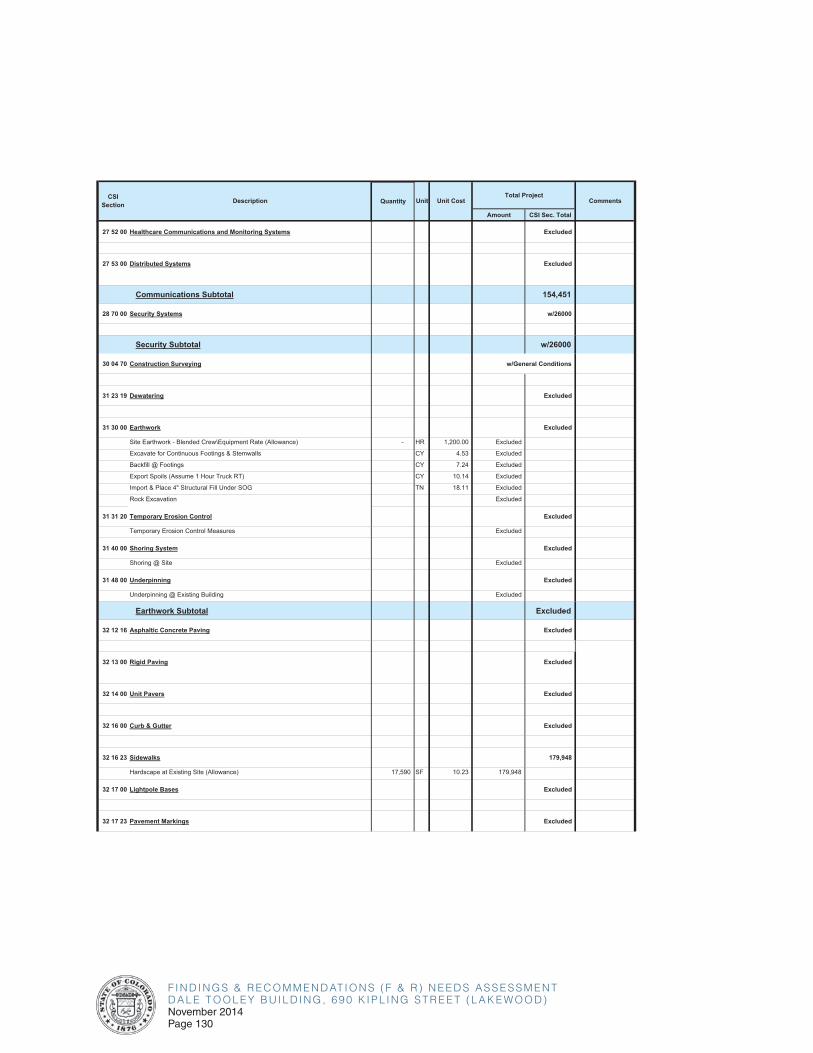
F I N D I N G S & R E C O M M E N D AT I O N S ( F & R ) N E E D S A S S E S S M E N TD A L E T O O L E Y B U I L D I N G , 6 9 0 K I P L I N G S T R E E T ( L A K E W O O D )November 2014Page 130
Amount CSI Sec. Total
CSISection Description Unit Unit Cost CommentsQuantity
Total Project
27 52 00 Healthcare Communications and Monitoring Systems Excluded
27 53 00 Distributed Systems Excluded
Communications Subtotal 154,451
28 70 00 Security Systems w/26000
Security Subtotal w/26000
30 04 70 Construction Surveying w/General Conditions
31 23 19 Dewatering Excluded
31 30 00 Earthwork Excluded
Site Earthwork - Blended Crew\Equipment Rate (Allowance) - HR 1,200.00 Excluded
Excavate for Continuous Footings & Stemwalls CY 4.53 Excluded
Backfill @ Footings CY 7.24 Excluded
Export Spoils (Assume 1 Hour Truck RT) CY 10.14 Excluded
Import & Place 4" Structural Fill Under SOG TN 18.11 Excluded
Rock Excavation Excluded
31 31 20 Temporary Erosion Control Excluded
Temporary Erosion Control Measures Excluded
31 40 00 Shoring System Excluded
Shoring @ Site Excluded
31 48 00 Underpinning Excluded
Underpinning @ Existing Building Excluded
Earthwork Subtotal Excluded
32 12 16 Asphaltic Concrete Paving Excluded
32 13 00 Rigid Paving Excluded
32 14 00 Unit Pavers Excluded
32 16 00 Curb & Gutter Excluded
32 16 23 Sidewalks 179,948
Hardscape at Existing Site (Allowance) 17,590 SF 10.23 179,948
32 17 00 Lightpole Bases Excluded
32 17 23 Pavement Markings Excluded
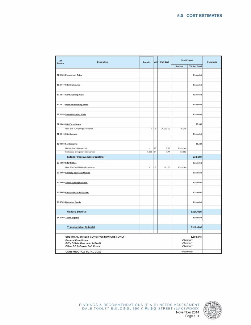
F I N D I N G S & R E C O M M E N D AT I O N S ( F & R ) N E E D S A S S E S S M E N TD A L E T O O L E Y B U I L D I N G , 6 9 0 K I P L I N G S T R E E T ( L A K E W O O D )
November 2014Page 131
5.0 COST ESTIMATES
Amount CSI Sec. Total
CSISection Description Unit Unit Cost CommentsQuantity
Total Project
32 31 00 Fences and Gates Excluded
32 31 17 Site Enclosures Excluded
32 32 13 CIP Retaining Walls Excluded
32 32 23 Modular Retaining Walls Excluded
32 32 50 Stone Retaining Walls Excluded
32 39 00 Site Furnishings 25,000
New Site Furnishings Allowance 1 LS 25,000.00 25,000
32 39 13 Site Signage Excluded
32 90 00 Landscaping 33,562
Native Seed (Allowance) - SF 0.81 Excluded
Softscape & Irrigation (Allowance) 7,036 SF 4.77 33,562
Exterior Improvements Subtotal 238,510
33 10 00 Site Utilities Excluded
New Wet\Dry Utilities (Allowance) - LF 121.00 Excluded
33 30 00 Sanitary Sewerage Utilities Excluded
33 40 00 Storm Drainage Utilities Excluded
33 46 00 Foundation Drain System Excluded
33 47 00 Detention Ponds Excluded
Utilities Subtotal Excluded
34 41 00 Traffic Signals Excluded
Transportation Subtotal Excluded
do not delete
do not delete
SUBTOTAL: DIRECT CONSTRUCTION COST ONLY 5,693,048 do not delete
General ConditionsGC's Offiste Overhead & Profit
do not delete
Other GC & Owner Soft Costs
do not delete CONSTRUCTION TOTAL COST w/Summary
w/Summaryw/Summary
w/Summary

F I N D I N G S & R E C O M M E N D AT I O N S ( F & R ) N E E D S A S S E S S M E N TD A L E T O O L E Y B U I L D I N G , 6 9 0 K I P L I N G S T R E E T ( L A K E W O O D )November 2014Page 132
This page left intentionally blank.


![[XLS]KDCB Music Library - Home | SESD Music Department · Web viewZoot Suit Riot Perry, Steve Kennard-Dale Kennard-Dale Kennard-Dale Kennard-Dale Kennard-Dale Kennard-Dale Kennard-Dale](https://img.dokumen.tips/doc/110x75/5b1a7c437f8b9a28258d8e9a/xlskdcb-music-library-home-sesd-music-web-viewzoot-suit-riot-perry-steve.jpg)