Embed Size (px)
Citation preview
STATE DEPARTMENT OF LIVESTOCK
MINISTRY OF AGRICULTURELIVESTOCK AND FISHERIES
Dairy ProductionStructures Manual
2
DAIRY PRODUCTION STRUCTURES MANUAL
Dairy Production Structures Manual
3
DAIRY PRODUCTION STRUCTURES MANUAL
Table of Contents
1.0 Introduction 41.1 Structures in a smallholder dairy production context 41.2 Challenges 41.3 Objective 4
2.0 Zero Grazing Unit 52.1 Description of a zero grazing unit 52.1.1 Parts of a zero grazing unit 52.1.2 Cubicles (resting area) 52.1.3 Walking area 62.1.4 Feed and water troughs 72.1.5 Milking area 72.1.6 Calf pen 72.1.7 Fodder-chopping area 82.1.8 Store 82.1.9 Slurry pit (manure collection) 82.2 Advantages of zero grazing 82.3 Disadvantages of zero grazing 82.4 Considerations for construction of a zero grazing unit 92.5 Construction plans and designs of a zero grazing unit 102.6 Construction materials required for of a zero grazing unit 132.7 Biogas technology 142.7.1 Description of biogas unit 142.7.2 Importance 142.7.3 Design 152.7.4 Materials and costs 15
3.0 Milking Parlour/Sheds 173.1 Description of a milking parlour 173.2 Importance 173.3 Materials and costs 23
4.0 Calf Pens 194.1 Description 194.2 Importance 194.3 Siting 194.4 Materials 194.5 Design 204.6 Economics 21
4
DAIRY PRODUCTION STRUCTURES MANUAL
5.0 Crush Pens 225.1 Description 225.2 Importance 225.3 Sitting 225.4 Materials and costs 225.5 Design 23
6.0 Storage Structures 256.1 Hay Barn 256.1.1 Description 256.1.2 Importance 256.1.3 Siting of hay barn 256.1.4 Design 256.1.5 Materials 266.1.6 Economics for standard hay barn to house 600 bales 276.2 Silo 296.2.1 Description 296.2.2 Importance 296.2.3 Types of silos 296.2.4 Siting of silos 306.2.5 Design 306.2.6 Materials 30
7.0 Feed and Water Troughs 317.1 Description 317.2 Materials 327.3 Cost 32
5
DAIRY PRODUCTION STRUCTURES MANUAL
1.0 Introduction
1.1 Structures in a smallholder dairy production contextVarious structures are required in dairy rearing systems, including animal housing, feeding and feed storage structures. Dairy structures are useful for:
i. Promoting easy handling of animals (using the crush)ii. Confining animals to keep them away from cropsiii. Providing clean and hygienic conditions (e.g. for milk production)iv. Close monitoring of animal status v. Controlling/monitoring exposure to disease and disease vectorsvi. Reducing feed wastagevii. Enhancing security of the animalsviii. Enhancing manure collectionix. Safekeeping of feed
This manual describes the various types of dairy structures: zero grazing units, milking parlours/sheds, calf pens, crush pens, including feed, water and mineral troughs. It also describes benefits and the resources needed for their construction.
1.2 ChallengesSmallholder dairy farmers normally work with limited resources including land. This poses challenges related to space for construction of dairy structures. The mainly resource-poor farmers also face limitations in terms of meeting costs associated with putting in place the required dairy structures. Most smallholder farmers also lack technical skills that are necessary to optimally work with their little resources to provide the appropriate dairy structures. This is because most technical manuals feature standard recommendations that are not convenient in the context of smallholders.
1.3 ObjectiveThe objective of this manual is therefore to provide simple, applicable and appropriate technical information for use by farmers and extension agents in choosing, designing and using smallholder dairy structures. The manual does not extensively address the aspects of farm planning. Towards this end, it is suggested that farmers can seek individual farm-specific advice and plans from the livestock extension agents.
6
DAIRY PRODUCTION STRUCTURES MANUAL
2.0 Zero Grazing Unit
2.1 Description of a zero grazing unitUnder the zero-grazing system, cattle are confined in one place where feed and water are brought to the animals. Other animal husbandry activities such as animal health, are also carried out under zero grazing. Zero-grazing is a good system for keeping dairy cattle in densely populated, high potential areas, where land per farm family is small. Other dairy cattle rearing systems which also require housing are semi-zero grazing and free grazing. Different dairy cattle rearing systems have different requirement for housing although they share some common needs.
In this booklet, explanations are given about the layout and construction of a zero-grazing unit. The guidelines contained here are mainly for farmers in high potential areas of Kenya. Because of climatic difference between the Coastal strip and the highland areas, a separate booklet has been prepared for farmers at the Coast.
2.1.1 Parts of a zero grazing unitThe basic parts in a semi-zero-grazing system are the feed and water troughs and the milking place. The cubicles and walking area are optional. These options, in both zero-grazing and semi zero-grazing systems, are necessary when the farmer has inadequate finance and cannot meet the labour and high skills demanded by the zero-grazing option.
The parts of a zero grazing unit can best be summarized in a table form as follows:
Table 1: Parts of a zero grazing unit
Basic (Essential) parts: Basic (Essential) Parts
1. The cubicles2. The walking area3. The feed and water troughs4. The milking place5. The calf pen6. The fodder chopping area
7. The store8. The manure storage9. Fodder cutter10. Roof water catchment11. Water tank12. A holding crush
2.1.2 Cubicles (resting area)Each cow has her own place in the resting area, called cubicle. The cubicles must be covered with a roof of mabati (iron sheets), grass thatch or makuti. A roof must be high enough so that it cannot be eaten by a cow if it is made of grass or if hay is stored under it. The measurements of the cubicle are very important. It should not be too small for the cow or too big to allow the cow to turn around inside the cubicle. The cubicle should be constructed such that the cow remains clean all the time.
One should construct a number of cubicles enough to be occupied by animals most of the time. Unoccupied cubicles are a waste of space and money. For a given number of cows to a unit, extra cubicles are required to house young-stock (heifers). If young bulls are to be kept inside the unit (although this is not recommended), then they must be provided with cubicles. When the bull matures, it is better to house it away from the unit.
7
DAIRY PRODUCTION STRUCTURES MANUAL
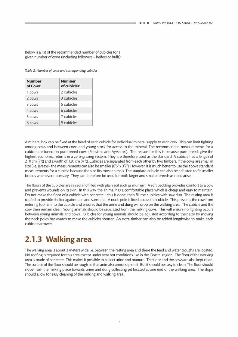
Below is a list of the recommended number of cubicles for a given number of cows (including followers – heifers or bulls):
Table 2: Number of cows and corresponding cubicles
Number of Cows:
Number of cubicles:
1 cows 2 cubicles
2 cows 3 cubicles
3 cows 5 cubicles
4 cows 6 cubicles
5 cows 7 cubicles
6 cows 9 cubicles
A mineral box can be fixed at the head of each cubicle for individual mineral supply to each cow. This can limit fighting among cows and between cows and young stock for access to the mineral. The recommended measurements for a cubicle are based on pure breed cows (Friesians and Ayrshires). The reason for this is because pure breeds give the highest economic returns in a zero-grazing system. They are therefore used as the standard. A cubicle has a length of 210 cm (7ft) and a width of 120 cm (4 ft). Cubicles are separated from each other by two timbers. If the cows are small in size (i.e. Jerseys), the measurements can also be smaller (6’6” x 3’7”). However, it is much better to use the above standard measurements for a cubicle because the size fits most animals. The standard cubicle can also be adjusted to fit smaller breeds whenever necessary. They can therefore be used for both larger and smaller breeds as need arise.
The floors of the cubicles are raised and filled with plain soil such as murrum. A soft bedding provides comfort to a cow and prevents wounds on its skin. In this way, the animal has a comfortable place which is cheap and easy to maintain. Do not make the floor of a cubicle with concrete. I this is done, then fill the cubicles with saw dust. The resting area is roofed to provide shelter against rain and sunshine. A neck-pole is fixed across the cubicle. This prevents the cow from entering too far into the cubicle and ensures that the urine and dung will drop on the walking area. The cubicle and the cow then remain clean. Young animals should be separated from the milking cows. This will ensure no fighting occurs between young animals and cows. Cubicles for young animals should be adjusted according to their size by moving the neck-poles backwards to make the cubicles shorter. An extra timber can also be added lengthwise to make each cubicle narrower.
2.1.3 Walking areaThe walking area is about 3 meters wide i.e. between the resting area and there the feed and water troughs are located. No roofing is required for this area except under very hot conditions like in the Coastal region. The floor of the working area is made of concrete. This makes it possible to collect urine and manure. The floor and the cows are also kept clean. The surface of the floor should be rough so that animals cannot slip on it. But it should be easy to clean. The floor should slope from the milking place towards urine and dung collecting pit located at one end of the walking area. The slope should allow for easy cleaning of the milking and walking area.
8
DAIRY PRODUCTION STRUCTURES MANUAL
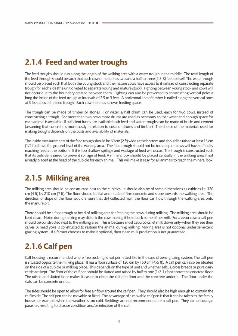
2.1.4 Feed and water troughsThe feed troughs should run along the length of the walking area with a water trough in the middle. The total length of the feed through should be such that each cow or heifer has two and a half to three (2.5-3) feet to itself. The water trough should be placed such that both the young stock and the mature cows have access to it instead of constructing separate trough for each side (the unit divided to separate young and mature stock). Fighting between young stock and cows will not occur due to the boundary created between them. Fighting can also be prevented to constructing vertical poles a long the inside of the feed trough at intervals of 2.5 to 3 feet. A horizontal line of timber is nailed along the vertical ones at 3 feet above the feed trough. Each cow then has its own feeding space.
The trough can be made of timber or stones. For water, a half drum can be used, each for two cows, instead of constructing a trough. For more than two cows more drums are used as necessary so that water and enough space for each animal is available. If sufficient funds are available both feed and water troughs can be made of bricks and cement (assuming that concrete is more costly in relation to costs of drums and timber). The choice of the materials used for making troughs depends on the costs and availability of materials.
The inside measurements of the feed trough should be 60 cm (2 ft) wide at the bottom and should be raised at least 15 cm (1/2 ft) above the ground level of the walking area. The feed trough should not be too deep or cows will have difficulty reaching feed at the bottom. If it is too shallow, spillage and wastage of feed will occur. The trough is constructed such that its outside is raised to prevent spillage of feed. A mineral box should be placed centrally in the walking area if not already placed at the head of the cubicle for each animal. This will make it easy for all animals to reach the mineral box.
2.1.5 Milking areaThe milking area should be constructed next to the cubicles. It should also be of same dimensions as cubicles i.e. 120 cm (4 ft) by 210 cm (7 ft). The floor should be flat and made of firm concrete and slope towards the walking area. The direction of slope of the floor would ensure that dirt collected from the floor can flow through the walking area onto the manure pit.
There should be a feed trough at head of milking area for feeding the cows during milking. The milking area should be kept clean. Noise during milking may disturb the cow making it hold back some of her milk. For a zebu cow, a calf pen should be constructed next to the milking area. This is because most zebu cows let milk down only-when they see their calves. A head yoke is constructed to restrain the animal during milking. Milking area is not optional under semi-zero grazing system. If a farmer chooses to make it optional, then clean milk production is not guaranteed.
2.1.6 Calf pen Calf housing is recommended where free suckling is not permitted like in the case of zero-grazing system. The calf pen is situated opposite the milking place. It has a floor surface of 120 cm by 150 cm (4x5 ft). A calf pen can also be situated on the side of a cubicle or milking place. This depends on the type of unit and whether zebus, cross breeds or pure dairy cattle are kept. The floor of the calf pen should be slatted and raised by half to one (1/2-1) foot above the concrete floor. The raised and slatted floor makes it easier to clean the calf pen floor and the concrete under it. The floor under the slats can be concrete or not.
The sides should be open to allow for free air flow around the calf pen. They should also be high enough to contain the calf inside. The calf pen can be movable or fixed. The advantage of a movable calf pen is that it can be taken to the family house, for example when the weather is too cold. Beddings are not recommended for a calf pen. They can encourage parasites resulting to disease condition and/or infection of the calf.
9
DAIRY PRODUCTION STRUCTURES MANUAL
2.1.7 Fodder-chopping area This place is for a fodder chopping equipment (chaff cutter) and the chopped fodder. It is situated opposite the store next to the calf pen. It is also placed under the roof. The fodder chopping area floor can be made of concrete to avoid the feed getting mixed with soil.
A fodder chopper is recommended if there are more than three cows in the unit and where labour on the farm, is generally inadequate. One can chop napier grass or any other fodder in an open space next to the unit, therefore, a fodder-chopping area is optional.
2.1.8 StoreIf required, a store can be attached to the zero-grazing unit next to the milking place and opposite the fodder-chopping area. In this way, concentrates, minerals, milk utensils and other small equipments can be stored near to the animals. A store is optional where finances are inadequate. It can however be built later-on when funds are available. Inputs like dairy meal and drugs are kept in the living house before a store is built. When building a store, rainwater collection facilities and cemented floor are optional.
2.1.9 Slurry pit (manure collection)The slurry can be stored in a small pit dug out of the soil. The pit mayor may not be cemented. Manure can also be stored as compost made from dung, urine and plant materials. In this case the compost is heaped next to the unit. Compost may be covered with soil or plastic. The dairy or livestock extension officer will provide the right measurements for the size of the pit to hold slurry (manure) for at-least two days for any number of cows in the unit.
2.2 Advantages of zero grazingThe main advantages of the zero-grazing system are:
• Cowsareconfinedandthereforeusemostoftheenergyfromfeedsforgrowthandmilkproduction.• Saveslandforotherenterprisesbyallowingtheuseofhighyieldingfoddercropslikenapier• Cleanmilkproductionispossible.• Goodcalfrearingispossible• Manurecanbeeasilycollectedforthebenefitoffoddercrops• Theanimalsarebetterprotectedagainstdiseases,especiallytick-bornediseases.• Closeobservationoftheanimalsispossible,makingheatdetectionandattendancetoanimalseasierandfaster.• Theanimalsarekeptinsidewhichismoresecureandprotectthemfromattackbypredators• Littleornotimeisspentonherdingtheanimals.Thereforelabourforotherfarmtasksissaved.
2.3 Disadvantages of zero grazingThe disadvantages of the zero-grazing system are:• Muchlabourisrequiredtotakefeedandwatertotheanimals.• Muchcapitalisrequiredforconstructionofa‘zero-grazingunit.• Thepossibilitythatanimalsarestressedbecauseoftoomuchconfinementinsidethezerograzingunitis
introduced by the National Dairy Development Project (NDDP) consists of the following parts listed below, some of which are optional.
10
DAIRY PRODUCTION STRUCTURES MANUAL
Zero-grazing system requires intensive (a lot of) labour for cutting and carrying napier grass, milking and a carrying water and other feed materials to the animals. This means that the tasks of some of the family members may increase. Proper planning is therefore required before starting a zero-grazing system. This will enable the farmer to appreciate the high financial and labour demands of zero-grazing before getting involved.
Because zero-grazing requires a lot of money (capital) for the construction of the unit, it can be done in steps by first constructing the essential parts of a zero-grazing unit. Other parts can be added later-on as money becomes available.One option is starting with semi-zero grazing as a first step before turning to full zero-grazing unit. This can be the case where farm size is large enough to allow for range grazing.
2.4 Considerations for construction of a zero grazing unitThe following are strongly-recommended as considerations during construction of a unit:
i. Ensurethatthefundi(constructor)issupervisedbyaLivestockExtensionOfficerduringtheconstructionoftheunit.This is necessary because some parts (ie walking area, troughs) once constructed are permanent. Mistakes made during construction can be very costly.
ii. Ensure that the correct site, considering the direction of wind, is chosen for the unit. The choice of site influences the security and protection of animals from rain, sunshine and other weather effects.
iii. The unit should be closer to the house and on the opposite side of the wind. The location of the unit in relation to the house should ensure minimal smell from manure pit. It should be noted that it is more important to protect an animal from the rain than from wind or sunshine.
iv. Use of local materials for construction of the unit will reduce cost.
v. Finally, one should as much as possible, carry out regular maintenance of the zero-grazing unit while in use. This is usually very important for the walking area.
11
DAIRY PRODUCTION STRUCTURES MANUAL
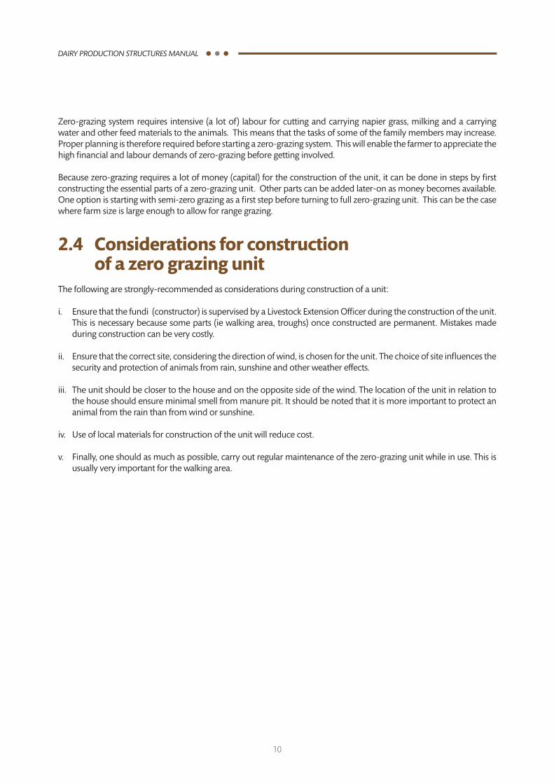
2.5 Construction plans and designs of a zero grazing uniti. Plan view – zero grazing units with 3 cubicles
Figure 2.1 Plan view – zero grazing unit with 3 cubicles
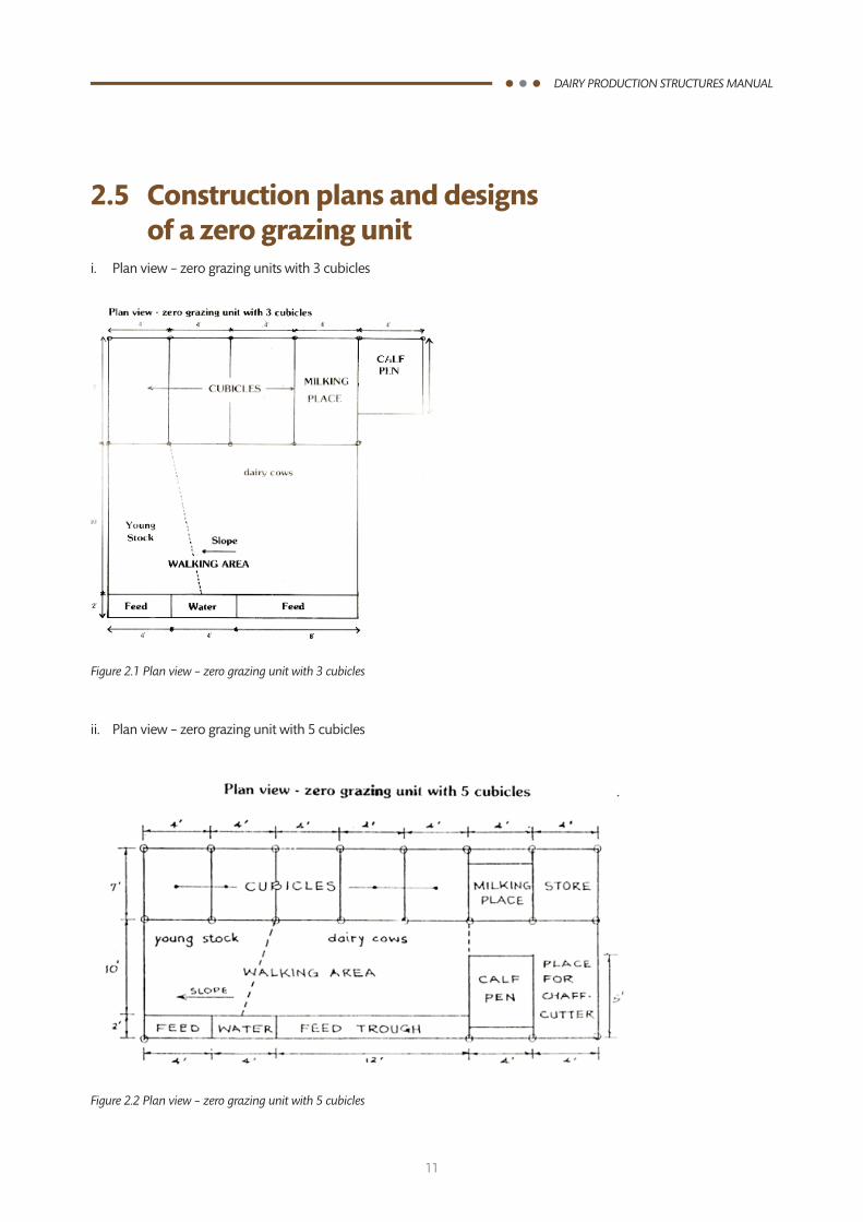
ii. Plan view – zero grazing unit with 5 cubicles
Figure 2.2 Plan view – zero grazing unit with 5 cubicles
12
DAIRY PRODUCTION STRUCTURES MANUAL
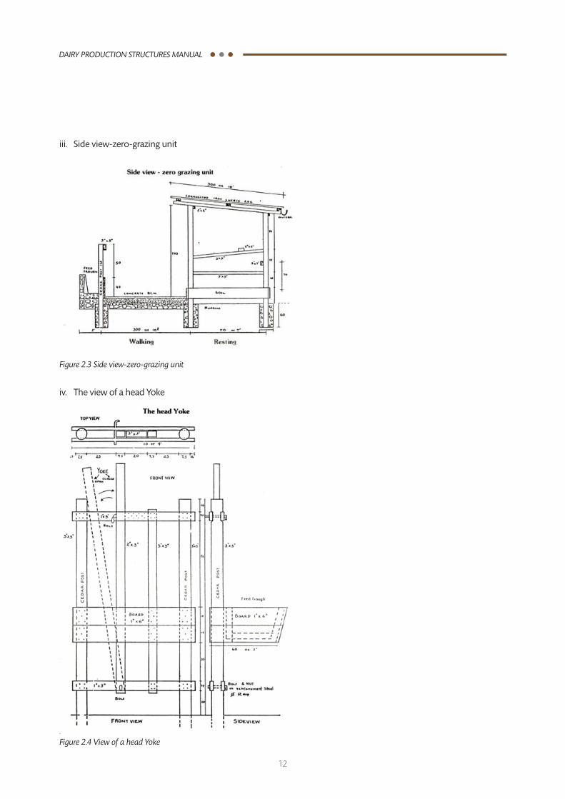
Figure 2.3 Side view-zero-grazing unit
iii. Side view-zero-grazing unit
iv. The view of a head Yoke
Figure 2.4 View of a head Yoke
13
DAIRY PRODUCTION STRUCTURES MANUAL
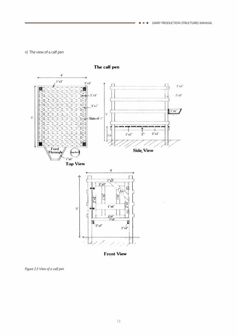
v) The view of a calf pen
Figure 2.5 View of a calf pen

14
DAIRY PRODUCTION STRUCTURES MANUAL
2.6 Construction materials required for of a zero grazing unit
Table 2.3 Materials for a zero grazing unit
Material Quantity
3 cubicle 5 cubicle
Strong posts (FT)
10 3 3
9.5 3 3
9 8 10
8.5 6 8
6 5* 6*
Timber (RFT)
4”x2” 190 250
3”x2” 330 370
2”x2” 100 100
3”x1” 13 13
8”x1” 15 15
Cement (Bags) 12 15
Iron Sheet (3M) 13 17
Ballast 4m3(1/2LorryLoad) 4m3(1/2LorryLoad)
Hardcore 3m3(1/2LorryLoad) 3m3(1/2LorryLoad)
Sand 3.5m3(1/2LorryLoad) 3.5m3(1/2LorryLoad)
Nails (Kg)
4” 3.5 3.5
3” 3.5 3.5
2’’ 2 2
Roofing nails 2 2
Additional materials for unit with roofed feeding area
Strong posts
7FT 2 3
6.5FT 3 5
Timber
3”x2” 52 80
Iron Sheet 2 3
* For a unit with a roofed feed area only 3 of the 6 FT posts are required.
15
DAIRY PRODUCTION STRUCTURES MANUAL
The Coastal region is very different climatically from the high potential areas where zero-grazing system is practiced. For this reason a specific booklet giving guidelines for the construction of a zero-grazing unit is available for farmers at the Coast. To prevent high investment costs, it is advisable to make use, as much as possible, of local materials and where possible from the farm. The cows will not notice the difference and will be equally productive.
2.7 Biogas technology
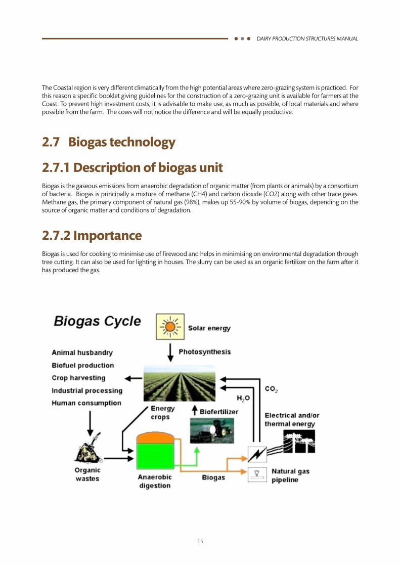
2.7.1 Description of biogas unitBiogas is the gaseous emissions from anaerobic degradation of organic matter (from plants or animals) by a consortium of bacteria. Biogas is principally a mixture of methane (CH4) and carbon dioxide (CO2) along with other trace gases. Methane gas, the primary component of natural gas (98%), makes up 55-90% by volume of biogas, depending on the source of organic matter and conditions of degradation.
2.7.2 ImportanceBiogas is used for cooking to minimise use of firewood and helps in minimising on environmental degradation through tree cutting. It can also be used for lighting in houses. The slurry can be used as an organic fertilizer on the farm after it has produced the gas.
16
DAIRY PRODUCTION STRUCTURES MANUAL
2.7.3 DesignThe biogas designs commonly used in Kenya are fixed dome, floating and plastic biodigesters. The choice of design and size of biogas unit depends on the financial ability of the farmer and the quantity of feeder material (primarily dung) available on the farm. The fixed dome design is most popular among smallholder dairy farmers due to its relative durability and physical security.
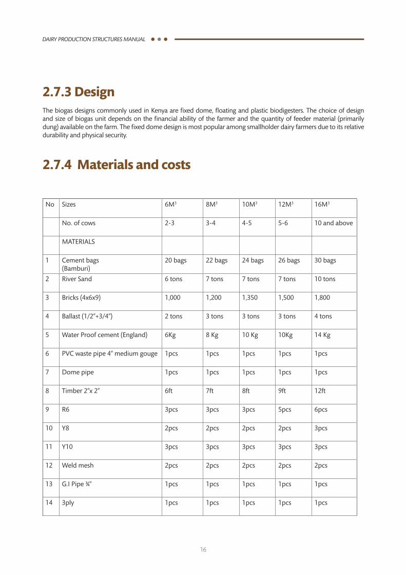
2.7.4 Materials and costs
No Sizes 6M3 8M3 10M3 12M3 16M3
No. of cows 2-3 3-4 4-5 5-6 10 and above
MATERIALS
1 Cement bags (Bamburi)
20 bags 22 bags 24 bags 26 bags 30 bags
2 River Sand 6 tons 7 tons 7 tons 7 tons 10 tons
3 Bricks (4x6x9) 1,000 1,200 1,350 1,500 1,800
4 Ballast (1/2”+3/4”) 2 tons 3 tons 3 tons 3 tons 4 tons
5 Water Proof cement (England) 6Kg 8 Kg 10 Kg 10Kg 14 Kg
6 PVC waste pipe 4” medium gouge 1pcs 1pcs 1pcs 1pcs 1pcs
7 Dome pipe 1pcs 1pcs 1pcs 1pcs 1pcs
8 Timber 2”x 2” 6ft 7ft 8ft 9ft 12ft
9 R6 3pcs 3pcs 3pcs 5pcs 6pcs
10 Y8 2pcs 2pcs 2pcs 2pcs 3pcs
11 Y10 3pcs 3pcs 3pcs 3pcs 3pcs
12 Weld mesh 2pcs 2pcs 2pcs 2pcs 2pcs
13 G.IPipe¾” 1pcs 1pcs 1pcs 1pcs 1pcs
14 3ply 1pcs 1pcs 1pcs 1pcs 1pcs
17
DAIRY PRODUCTION STRUCTURES MANUAL
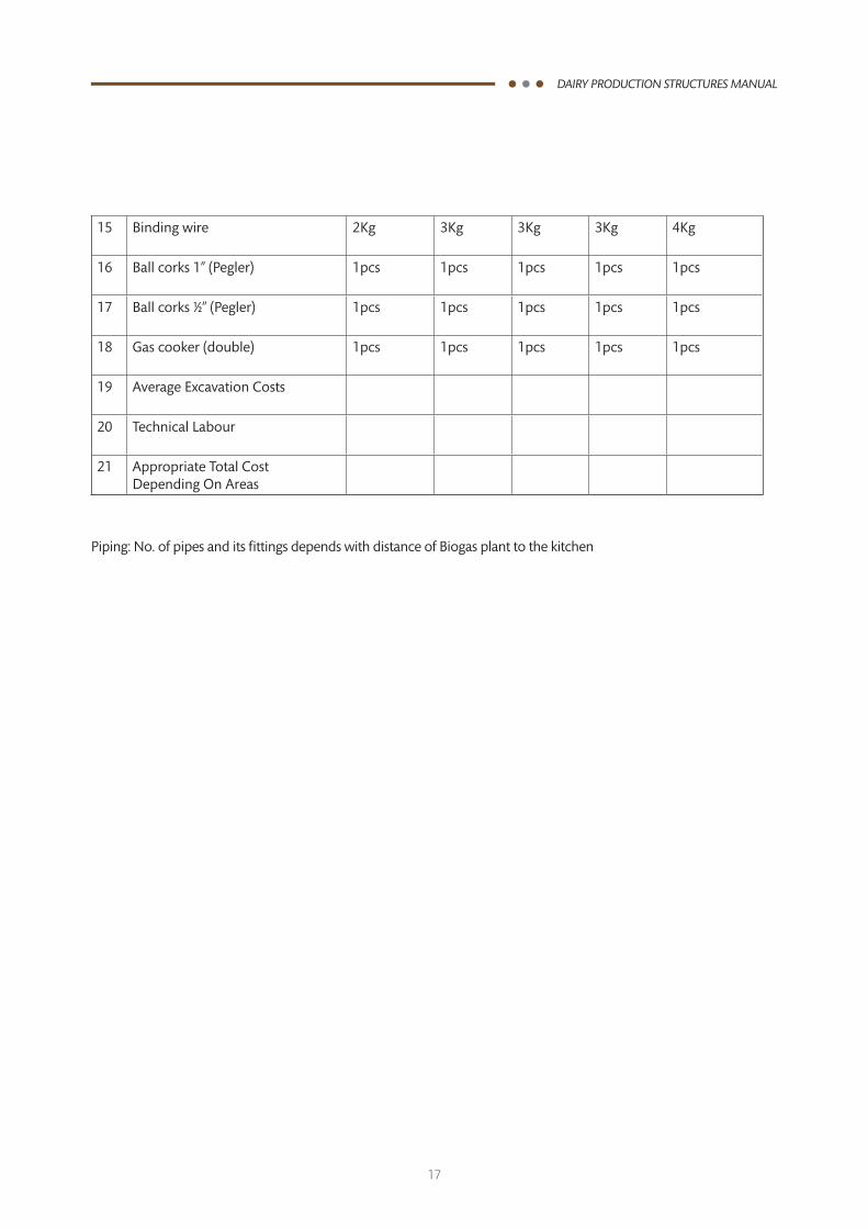
15 Binding wire 2Kg 3Kg 3Kg 3Kg 4Kg
16 Ball corks 1” (Pegler) 1pcs 1pcs 1pcs 1pcs 1pcs
17 Ball corks ½” (Pegler) 1pcs 1pcs 1pcs 1pcs 1pcs
18 Gascooker(double) 1pcs 1pcs 1pcs 1pcs 1pcs
19 Average Excavation Costs
20 TechnicalLabour
21 Appropriate Total Cost Depending On Areas
Piping: No. of pipes and its fittings depends with distance of Biogas plant to the kitchen
18
DAIRY PRODUCTION STRUCTURES MANUAL
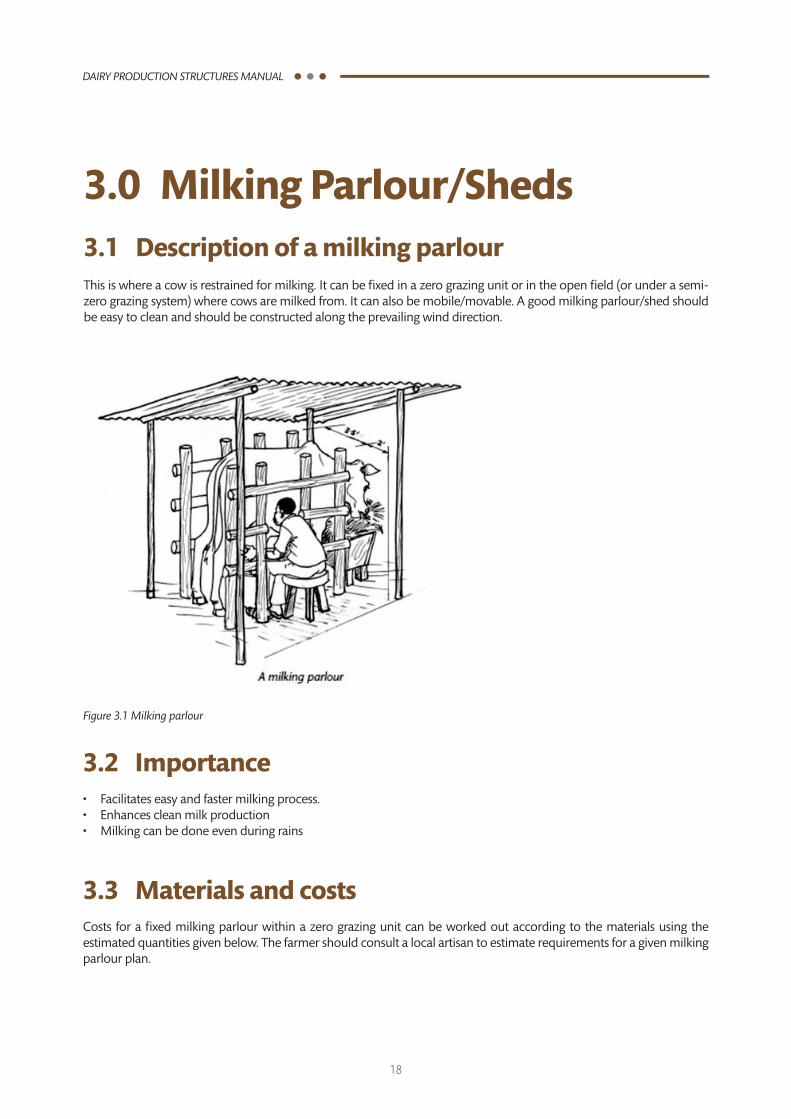
3.0 Milking Parlour/Sheds3.1 Description of a milking parlourThis is where a cow is restrained for milking. It can be fixed in a zero grazing unit or in the open field (or under a semi-zero grazing system) where cows are milked from. It can also be mobile/movable. A good milking parlour/shed should be easy to clean and should be constructed along the prevailing wind direction.
Figure 3.1 Milking parlour
3.2 Importance• Facilitateseasyandfastermilkingprocess.• Enhancescleanmilkproduction• Milkingcanbedoneevenduringrains
3.3 Materials and costsCosts for a fixed milking parlour within a zero grazing unit can be worked out according to the materials using the estimated quantities given below. The farmer should consult a local artisan to estimate requirements for a given milking parlour plan.
19
DAIRY PRODUCTION STRUCTURES MANUAL
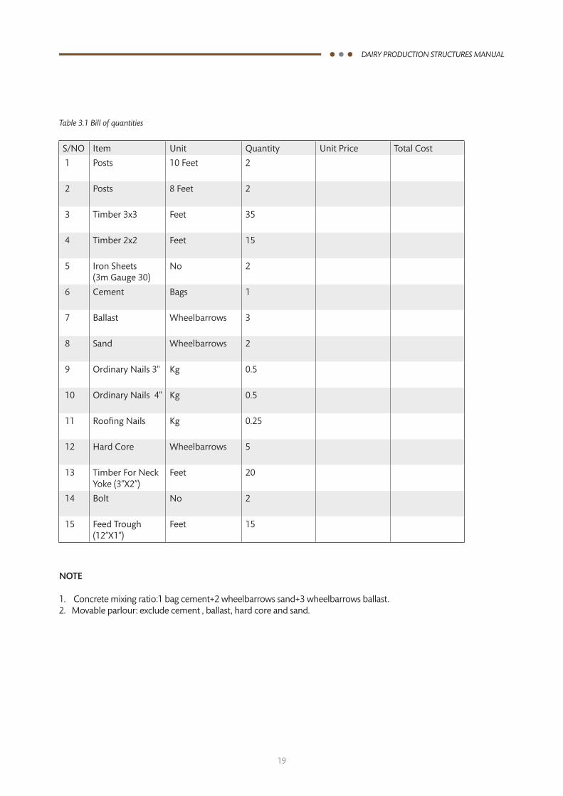
Table 3.1 Bill of quantities
S/NO Item Unit Quantity Unit Price Total Cost
1 Posts 10 Feet 2
2 Posts 8 Feet 2
3 Timber 3x3 Feet 35
4 Timber 2x2 Feet 15
5 Iron Sheets (3mGauge30)
No 2
6 Cement Bags 1
7 Ballast Wheelbarrows 3
8 Sand Wheelbarrows 2
9 Ordinary Nails 3" Kg 0.5
10 Ordinary Nails 4" Kg 0.5
11 Roofing Nails Kg 0.25
12 Hard Core Wheelbarrows 5
13 Timber For Neck Yoke (3”X2”)
Feet 20
14 Bolt No 2
15 Feed Trough (12”X1”)
Feet 15
NOTE
1. Concrete mixing ratio:1 bag cement+2 wheelbarrows sand+3 wheelbarrows ballast.2. Movable parlour: exclude cement , ballast, hard core and sand.
20
DAIRY PRODUCTION STRUCTURES MANUAL
4.0 Calf Pens4.1 DescriptionThis is a specially designed unit to house a growing calf. It can be fixed (within or separate from the zero grazing unit) or movable (common in ranches and free grazing systems). A calf pen allows close and frequent monitoring of the calf, eases planning and monitoring of the feeding regime and supports high standards of hygiene and disease control. However, it is a labour-intensive choice, since the calf is fully dependant on the stockowner for feed and water.
4.2 Importancei. Protection from adverse weather conditions and predators, ii. Avoid internal and external parasitesiii. Control feeding and management.iv. Allows monitoring by close observation
When it is not possible to have individual calf pens then group housing can be done though there are several disadvantages including:
i. Difficulty in feeding and management.ii. Disease control is difficult.iii. Decreased growth rate due to fights among calves iv. Calves suckling each other which could lead to ingested hair (tend to form hairballs).
4.3 Sitingi. It is normally placed inside the roofed and walled section of the zero gazing units. ii. can be situated on the side of the cubicle or opposite the milking placeiii. It may be permanent or movable.iv. Can also be build as a separate structure away from milking cows where calves are manyv. Should face away from the winds but allow free air circulation
4.4 Materials i. A calf pen should be constructed where possible from locally available materials. ii. The sides (walls) can be made of concrete or wooden poles or steel polesiii. Floor for fixed pens should be of concrete with bedding or wooden slatsiv. Movable pens can have a raised slatted floor (or an earth floor if the site has good drainage)v. Roof : should be of corrugated iron sheets or thatch.vi. Walls: wooden poles from farm timber or steel poles
21
DAIRY PRODUCTION STRUCTURES MANUAL
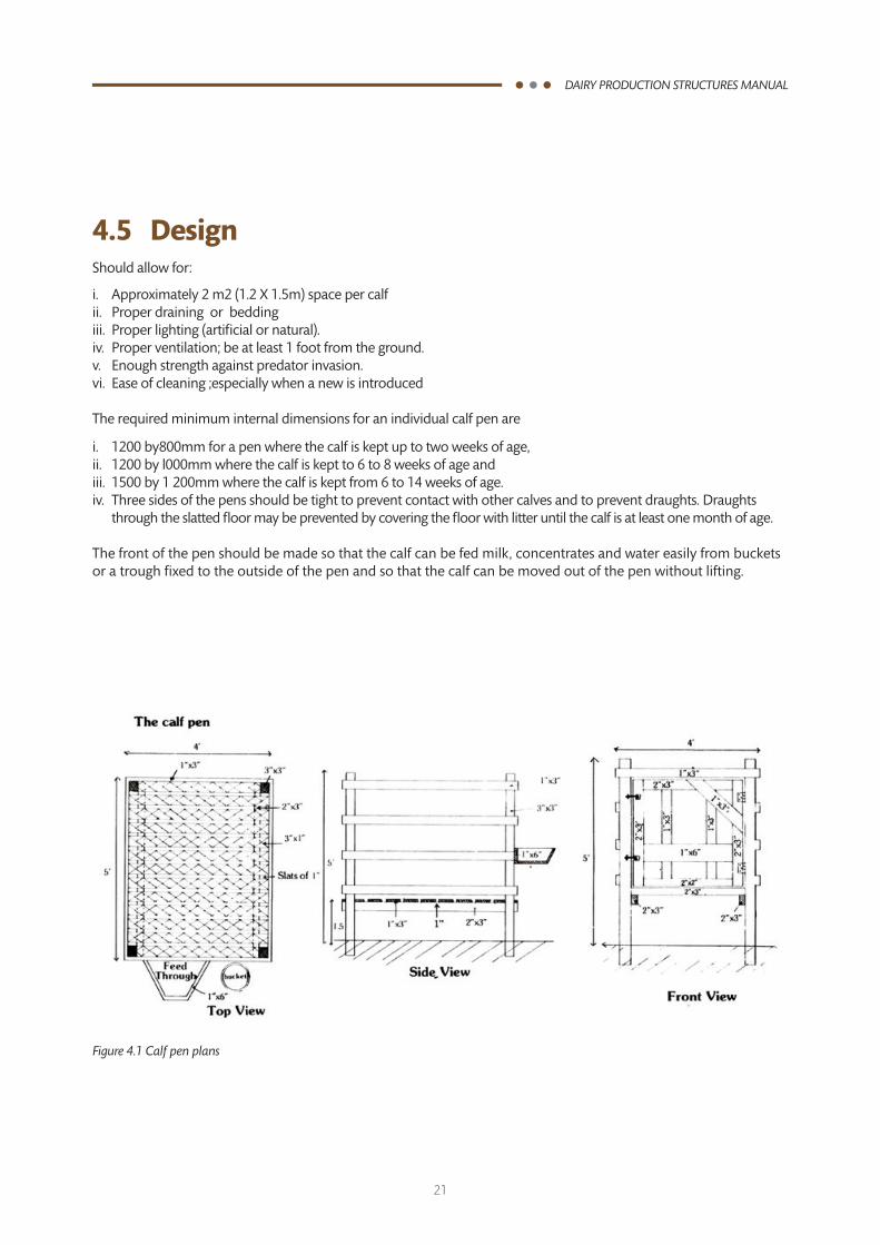
4.5 DesignShould allow for:
i. Approximately 2 m2 (1.2 X 1.5m) space per calfii. Proper draining or beddingiii. Proper lighting (artificial or natural).iv. Proper ventilation; be at least 1 foot from the ground.v. Enough strength against predator invasion.vi. Ease of cleaning ;especially when a new is introduced
The required minimum internal dimensions for an individual calf pen are
i. 1200 by800mm for a pen where the calf is kept up to two weeks of age, ii. 1200 by l000mm where the calf is kept to 6 to 8 weeks of age andiii. 1500 by 1 200mm where the calf is kept from 6 to 14 weeks of age.iv. Three sides of the pens should be tight to prevent contact with other calves and to prevent draughts. Draughts
through the slatted floor may be prevented by covering the floor with litter until the calf is at least one month of age.
The front of the pen should be made so that the calf can be fed milk, concentrates and water easily from buckets or a trough fixed to the outside of the pen and so that the calf can be moved out of the pen without lifting.
Figure 4.1 Calf pen plans
22
DAIRY PRODUCTION STRUCTURES MANUAL
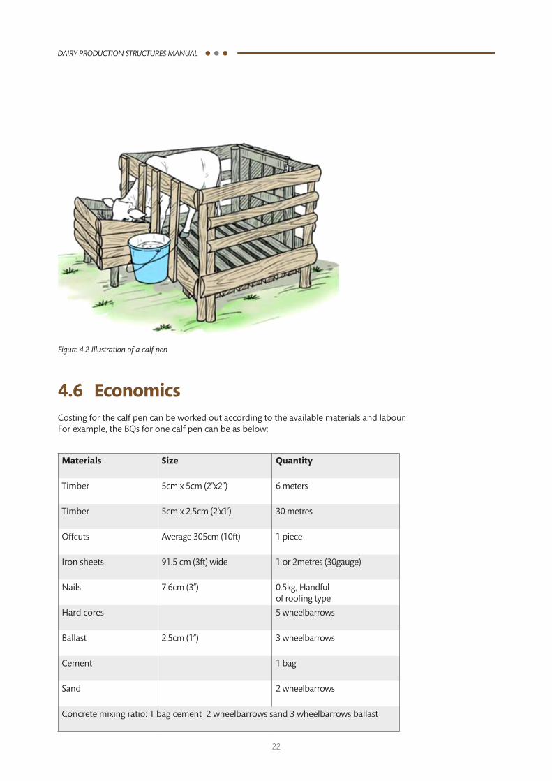
Figure 4.2 Illustration of a calf pen
4.6 EconomicsCosting for the calf pen can be worked out according to the available materials and labour.For example, the BQs for one calf pen can be as below:
Materials Size Quantity
Timber 5cm x 5cm (2’’x2’’) 6 meters
Timber 5cm x 2.5cm (2’x1’) 30 metres
Offcuts Average 305cm (10ft) 1 piece
Iron sheets 91.5 cm (3ft) wide 1 or 2metres (30gauge)
Nails 7.6cm (3’’) 0.5kg, Handful of roofing type
Hard cores 5 wheelbarrows
Ballast 2.5cm (1”) 3 wheelbarrows
Cement 1 bag
Sand 2 wheelbarrows
Concrete mixing ratio: 1 bag cement 2 wheelbarrows sand 3 wheelbarrows ballast
23
DAIRY PRODUCTION STRUCTURES MANUAL
5.0 Crush Pens5.1 DescriptionThis is a separate place for restraining an animal so that regular management practices (e.g. administering injections, deworming and hand spraying with insecticide) can be undertaken safely. Crush pens can be erected within or outside the zero grazing unit. Crush pens allow the stockowner to have close contact with the animal without risk of injury. It is also easier to make observations (external and internal organs) and administer drugs. However, the maintenance/repair costs will be high if constructed using fragile materials.
5.2 Importance.i. Restraining of the animal for easy handling by the owner or the livestock attendance that allows for;
• Administrationofdrugse.g.dewormersandotheroraldrugs,• Deworming,hooftrimming,eartagging,brandingetc,• Easyhandlingduringcalving,• Inspection/examinationofthecowbothexternallyandinternally,
ii. Breeding purposes(A.I. and Bull service),iii. Disease control (Spraying, vaccinations and treatment),iv. Safe-guarding the livestock owner or handler from risk of injuries.
5.3 Sitting i. The crush should be way from the Zero grazing unit on the leeward side.ii. Construction of the Crush pen to be done in to the direction of the wind.iii. It should be over 40m from the homesteads/neigbours.iv. It should be away from the milking area because milk is a good absorber of odour from the surrounding.
5.4 Materials and costsAlways use locally available materials. These include poles (roundish),frames ,Nails etc.
24
DAIRY PRODUCTION STRUCTURES MANUAL
No. MATERIAL SIZE QUANTITY UNIT COST (Kshs)
TOTAL COST(Kshs)
1 Timber 3”x2” 48 Rft of 6 pieces
2 Poles 6”x6’ 10
3 Nails 4” 0.5 kg
4 Hard core Assorted 4 wheelbarrows
5 Ballast 2,5cm(1”) 4 wheelbarrows
6 Cement - 1 bag (50kg)
7 Sand - 2 wheelbarrows
8 Transport costs - -
9 Labour - -
Total costs
Note: Costs of materials vary from place to place and from time to time. The farmer is advised to use locally available materials to save on cost of construction.
Assumptions
i. Cedar posts are locally available but may use treated poles.ii. It is recommended that the floor be firmed (cemented) for durability.
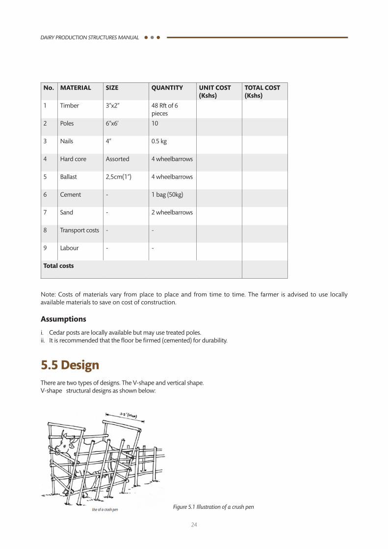
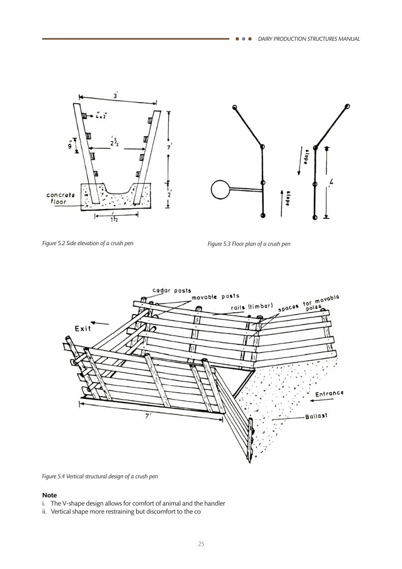
5.5 DesignThere are two types of designs. The V-shape and vertical shape.V-shape structural designs as shown below:
Figure 5.1 Illustration of a crush pen
25
DAIRY PRODUCTION STRUCTURES MANUAL
Figure 5.2 Side elevation of a crush pen Figure 5.3 Floor plan of a crush pen
Figure 5.4 Vertical structural design of a crush pen
Note i. The V-shape design allows for comfort of animal and the handlerii. Vertical shape more restraining but discomfort to the co
26
DAIRY PRODUCTION STRUCTURES MANUAL
6.0 Storage Structures6.1 Hay Barn
6.1.1 DescriptionA hay barn is used to store hay in (bales or loose), it is a simple structure constructed using locally available materials. A hay barn is useful to farmers who have a lot of grass and expect to use grass to feed cows later. It is also important to keep integrity of harvested hay so that cows are fed high quality dry forage.
6.1.2 Importancei. Protects hay against direct sunlight and rainii. Reduces loss of hay iii. Maintains quality of hayiv. Enables feed planningv. Prolongs the shelf life of hayvi. Provides security to hay
6.1.3 Siting of hay barnHay barn should be sited on a raised ground with good drainage and access to road. It should be situated close to zero grazing units. The ground and surrounding should be kept clean to avoid vermin such as rodents. Adequate space should be allowed for other farm implements i.e. tractor, lorry hand cats etc. and emergency equipments in case of fire. The open end should face away from the direction of wind. Hay ban should be located at least 75 ft from surrounding structures.
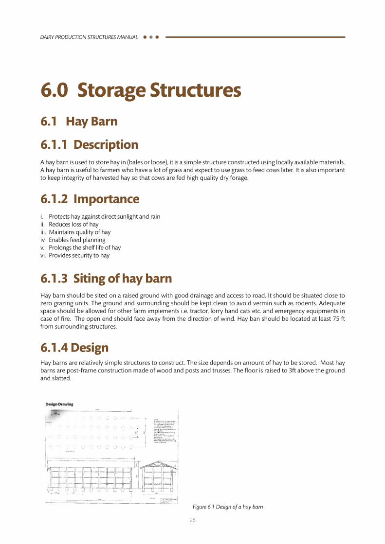
6.1.4 DesignHay barns are relatively simple structures to construct. The size depends on amount of hay to be stored. Most hay barns are post-frame construction made of wood and posts and trusses. The floor is raised to 3ft above the ground and slatted.
Figure 6.1 Design of a hay barn

27
DAIRY PRODUCTION STRUCTURES MANUAL
6.1.5 MaterialsAs a rule of the thumb, hay barn should be constructed from locally available materials. Depending on the size and design, one would need posts, corrugated iron sheets, nails and timber. It is recommended that the walls be well ventilated and made up of cheap but convenient materials such as off-cuts
6.1.6 Economics for standard hay barn to house 600 balesOne Acre of land, under good management can yield approximately 200 bales of Rhodes grass hay per harvesting each weighing approximately 15kg. A farmer would therefore, achieve 600 bales from three harvests in a year.
Table 6.1 Material estimates for a 600-bale hay barn
ITEM DESCRIPTION UNIT QUANTITY RATE (KSH) COST (KSH)
1 SITECLEARINGANDLEVELING
a. Clearing of vegetation, grass and tree stumps and removal of the same for safe disposal
M2 60.83 0 0
b. Site marking and layout Sum 1 3000 3000
2 FOUNDATION
a. Foundation holes
Excavation of foundation holes to a depth of 50cm and diameter 35cm at 125 x 148cm spacing to accommodate foundation posts
No 48 50 2400
b. Termite prevention and control
Apply anti termite pesticide in the dug foundation and wall posts holes using the correct concentration
L 1 1800 1800
c. Contrete collars
Prepare 1:3:6 concrete mix and pour in the foundation and walling holes.
M3
Ballast ton 3.5 2500 8,750
Sand ton 1.5 2500 3000
Cement bags 11 850 9,350
Foundation posts
Insert foundation timber treated posts 25cm diameter x 150cm lenght vertically in the fresh concrete filled holes.
No 28 900 25,200
28
DAIRY PRODUCTION STRUCTURES MANUAL
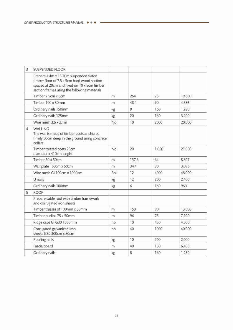
3 SUSPENDEDFLOOR
Prepare 4.4m x 13.70m suspended slated timber floor of 7.5 x 5cm hard wood section spaced at 20cm and fixed on 10 x 5cm timber section frames using the following materials
Timber 7.5cm x 5cm m 264 75 19,800
Timber 100 x 50mm m 48.4 90 4,356
Ordinary nails 150mm kg 8 160 1,280
Ordinary nails 125mm kg 20 160 3,200
Wire mesh 3.6 x 2.1m No 10 2000 20,000
4 WALLINGThe wall is made of timber posts anchored firmly 50cm deep in the ground using concrete collars
Timber treated posts 25cm diameter x 410cm lenght
No 20 1,050 21,000
Timber 50 x 50cm m 137.6 64 8,807
Wall plate 150cm x 50cm m 34.4 90 3,096
WiremeshGI100cmx1000cm Roll 12 4000 48,000
U nails kg 12 200 2,400
Ordinary nails 100mm kg 6 160 960
5 ROOF
Prepare cable roof with timber framework and corrugated iron sheets
Timber trusses of 100mm x 50mm m 150 90 13,500
Timber purlins 75 x 50mm m 96 75 7,200
RidgecapsGIG301500mm no 10 450 4,500
Corrugated galvanized iron sheetsG30300cmx80cm
no 40 1000 40,000
Roofing nails kg 10 200 2,000
Fascia board m 40 160 6,400
Ordinary nails kg 8 160 1,280
29
DAIRY PRODUCTION STRUCTURES MANUAL
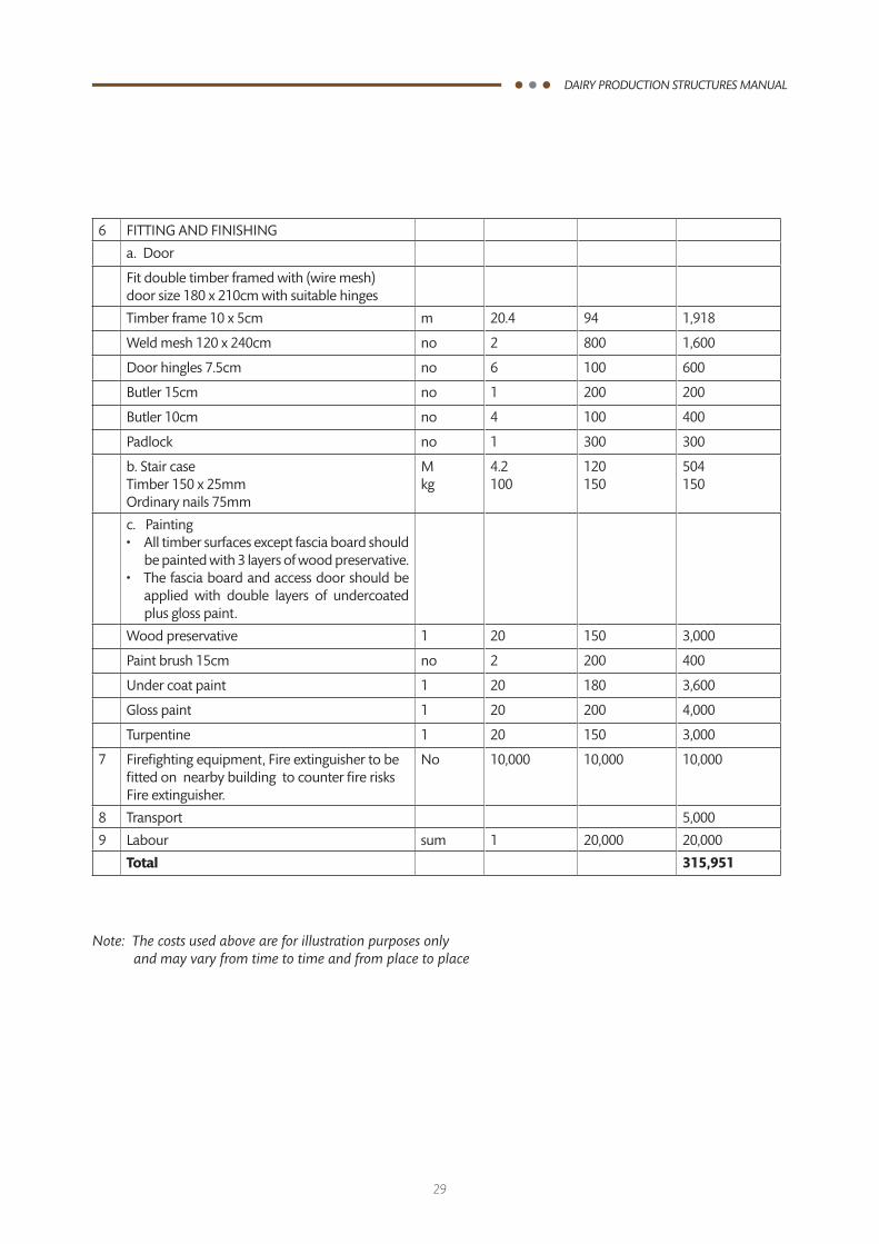
6 FITTINGANDFINISHING
a. Door
Fit double timber framed with (wire mesh) door size 180 x 210cm with suitable hinges
Timber frame 10 x 5cm m 20.4 94 1,918
Weld mesh 120 x 240cm no 2 800 1,600
Door hingles 7.5cm no 6 100 600
Butler 15cm no 1 200 200
Butler 10cm no 4 100 400
Padlock no 1 300 300
b. Stair case Timber 150 x 25mmOrdinary nails 75mm
Mkg
4.2100
120150
504150
c. Painting•Alltimbersurfacesexceptfasciaboardshould
be painted with 3 layers of wood preservative.•Thefasciaboardandaccessdoorshouldbe
applied with double layers of undercoated plus gloss paint.
Wood preservative 1 20 150 3,000
Paint brush 15cm no 2 200 400
Under coat paint 1 20 180 3,600
Glosspaint 1 20 200 4,000
Turpentine 1 20 150 3,000
7 Firefighting equipment, Fire extinguisher to be fitted on nearby building to counter fire risks Fire extinguisher.
No 10,000 10,000 10,000
8 Transport 5,000
9 Labour sum 1 20,000 20,000
Total 315,951
Note: The costs used above are for illustration purposes only and may vary from time to time and from place to place
30
DAIRY PRODUCTION STRUCTURES MANUAL
6.2 Silo
6.2.1 DescriptionA silo is used to store and secure silage. It is an air-tight and water-proof structure. A silo is an airtight place or receptacle for preserving green feed for future feeding on the farm. Silos can be either underground or above ground, the qualification being that the silo must allow compaction and be air tight. Five types are described here: tube, pit, above-ground, trench and tower. Silage can be made in large plastic sacks or tubes. The plastic must have no holes to ensure no air enters. This is popularly referred to as tube silage. Silage can also be made in pits that are dug vertically into the ground and then filled and compacted with the silage material.
6.2.2 ImportanceThe silo protects silage from air and water, which are the greatest enemy. It also enables feed planning since it is made in definite dimensions.
6.2.3 Types of silosTrench silo- Suitable for well-drained and sloppy areas Pit silo- Usually dug on the ground Above the ground/tower silo:-suitable for swampy areas
Diagram need to be clarified
31
DAIRY PRODUCTION STRUCTURES MANUAL
6.2.4 Siting of silosSilosareusuallysitedbasedontheirtypes.Generally,asiloshouldbesituatedclosetothepointofuseofthesilagei.e. Zero grazing unit and away from other farm structures to avoid disturbance.
6.2.5 DesignDesigns of silos depend on the sloppiness/gradient of the farm and site of the silo. The different types of silos have different designs.
6.2.6 MaterialsApart from the above ground/tower silo, other types of silos do not need any materials since they are dug on ground. To construct a tower silo one needs timber and nails. The amount if material needed depends on the material to be ensiled. As a general consideration, 1 acre of napier grass yields 7 tons per cutting and would require 5m x 3m x 1m silo. Pit and trench silos need labour to excavate ground to create the silo. Tower silo would need timber and nails. 5m x 3m x 1m silo would need 240 pieces of timber 6” by 1’’ each of 10 ft long and 8 kg of nails (4’’).
32
DAIRY PRODUCTION STRUCTURES MANUAL
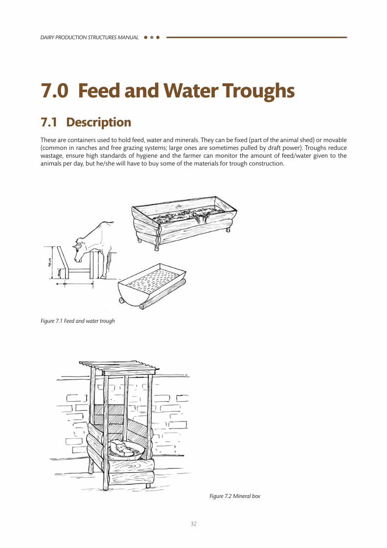
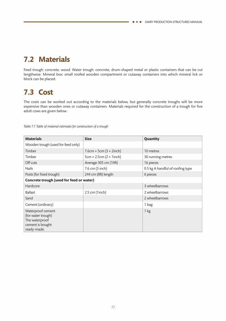
7.0 Feed and Water Troughs7.1 DescriptionThese are containers used to hold feed, water and minerals. They can be fixed (part of the animal shed) or movable (common in ranches and free grazing systems; large ones are sometimes pulled by draft power). Troughs reduce wastage, ensure high standards of hygiene and the farmer can monitor the amount of feed/water given to the animals per day, but he/she will have to buy some of the materials for trough construction.
Figure 7.1 Feed and water trough
Figure 7.2 Mineral box
33
DAIRY PRODUCTION STRUCTURES MANUAL
7.2 MaterialsFeed trough: concrete, wood. Water trough: concrete, drum-shaped metal or plastic containers that can be cut lengthwise. Mineral box: small roofed wooden compartment or cutaway containers into which mineral lick or block can be placed.
7.3 CostThe costs can be worked out according to the materials below, but generally concrete troughs will be more expensive than wooden ones or cutaway containers. Materials required for the construction of a trough for five adult cows are given below.
Table 7.1 Table of material estimates for construction of a trough
Materials Size Quantity
Wooden trough (used for feed only)
Timber 7.6cm × 5cm (3 × 2inch) 10 metres
Timber 5cm × 2.5cm (2 × 1inch) 30 running metres
Off cuts Average 305 cm (10ft) 16 pieces
Nails 7.6 cm (3 inch) 0.5 kg A handful of roofing type
Posts (for fixed trough) 244 cm (8ft) length 6 pieces
Concrete trough (used for feed or water)
Hardcore 3 wheelbarrows
Ballast 2.5 cm (1inch) 2 wheelbarrows
Sand 2 wheelbarrows
Cement (ordinary) 1 bag
Waterproof cement (for water trough) The waterproof cement is bought ready-made.
1 kg
34
DAIRY PRODUCTION STRUCTURES MANUAL
Notes
35
DAIRY PRODUCTION STRUCTURES MANUAL
Notes
36
DAIRY PRODUCTION STRUCTURES MANUAL
Smallholder Dairy Commercialization Programme (SDCP)Programme Coordination Unit
P.O. Box 12261-20100 Nakuru, Kenya.Tel: +254-51-2210851
E-mail: [email protected], [email protected] :www.sdcp.or.ke