Embed Size (px)
Citation preview
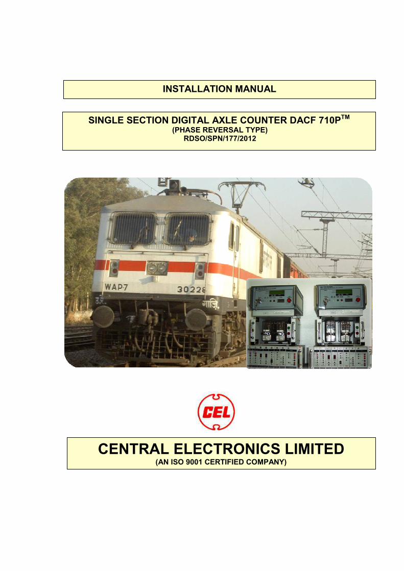
INSTALLATION MANUAL
SINGLE SECTION DIGITAL AXLE COUNTER DACF 710PTM
(PHASE REVERSAL TYPE) RDSO/SPN/177/2012
CENTRAL ELECTRONICS LIMITED (AN ISO 9001 CERTIFIED COMPANY)

DOCUMENT DATA SHEET
Title of Document : Installation Manual of SSDAC
Document Number
Version Number
Date of issue
:
:
CEL / DAC / IM – 04
Version 2.024.11.2017
System designed as per RDSO
Specification No. : RDSO / SPN / 177 / 2012 Ver. 3.0
Prepared By :
Railway Testing
System Production Division
Central Electronics Limited
Issued by : Production Engineering Department
Systems Division
Approved by : HOD, Systems Division
Central Electronics Limited
Approved by : Director Signal
RDSO, Lucknow
Abstract:
This document defines the installation & maintenance procedure for Single Section Digital Axle
Counter.
i

MESSAGE FROM OUR CMD
Dear SSDAC Customer,
We are privileged for your decision to choose SSDAC for modernization of signalling
in the Railways. The SSDAC comes to you backed by the trusted CEL brand and is part
of the Microprocessor and Software based Signalling Systems for Track Circuiting and
Block Working application.
We would want you to get acquainted with the details in the installation manual,
which will enable you to derive the best performance from your SSDAC. We look
forward to having you as a satisfied customer and hope to have you retain us, as your
first choice for any of your signalling needs.
Yours Sincerely
Chairman & Managing Director,
Central Electronics Limited.
ii
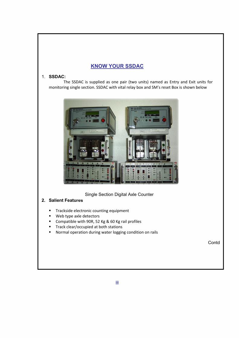
KNOW YOUR SSDAC
1. SSDAC: The SSDAC is supplied as one pair (two units) named as Entry and Exit units for
monitoring single section. SSDAC with vital relay box and SM’s reset Box is shown below
2. Salient Features
Trackside electronic counting equipment
Web type axle detectors
Compatible with 90R, 52 Kg & 60 Kg rail profiles
Track clear/occupied at both stations
Normal operation during water logging condition on rails
Contd
iii
Single Section Digital Axle Counter
3. System Design
Designed as per CENELEC, SIL-4 (European standard)
21 KHz & 23 KHz high frequency ‘Phase Reversal’ type axle detectors
Micro controller based design with 2 out of 2 decision
V 21 modem communication on ½ quad cable
Compatible to work on voice channel of OFC & Radio
Opto isolated relay drive for Q type 24V, 1000 ohm.
MTBF is greater than 20 years.
4. Application:
The system can be widely used in Railways for
Block Working
Intermediate block signaling
Auto signalling
Track circuiting for
i) Loop line ii) Main line iii) yard lines
5. Input, Output & Power Supply:
• Input: i) High Frequency axle detectors
ii) V 21 Modem
iii) Reset command of 48V dc.
• Output: i) Q type 24V, 1000 ohm Vital Relay.
ii) Q type 24V, 1000 ohm Prep. Relay.
iii) Monitor port RS232.
iv) Event logger card (Flash Memory).
• Power Supply: 24 V DC battery or 24 V DC from IPS
iv

For your kind attention
The Single Section Digital Axle Counter (SSDAC) is supplied with Phase reversal type Axle detectors. The
system model nos. is as follows:
The technical features of the above model are:
1. Phase reversal type Axle detectors. Track circuit connection into the system is not required for trolley
suppression.
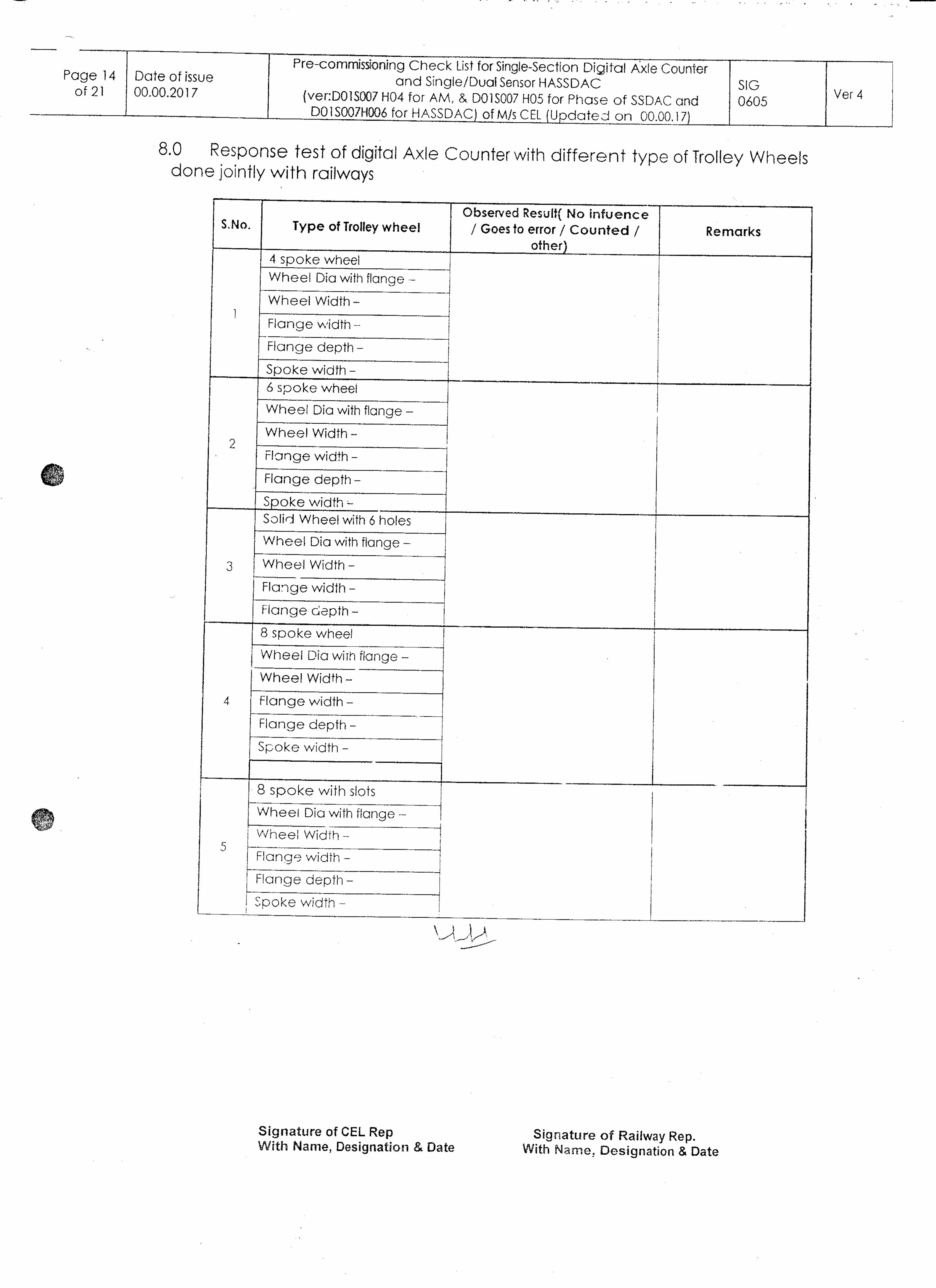
i) The push trolleys by which the system is not affected are
a) 4 spoke trolley; b) 8 spoke trolley; and c) rail dolly.
4/8 spokes push trollies shall have the following parameters for not affecting the system.
A) Flange Height < 22mm+/- 2mm, B) Flange width< 10mm, C) wheel base < 100 mm.
There shall be no Rim inside the wheel and orientation of spokes shall be in the plane to allow
passage to flux.
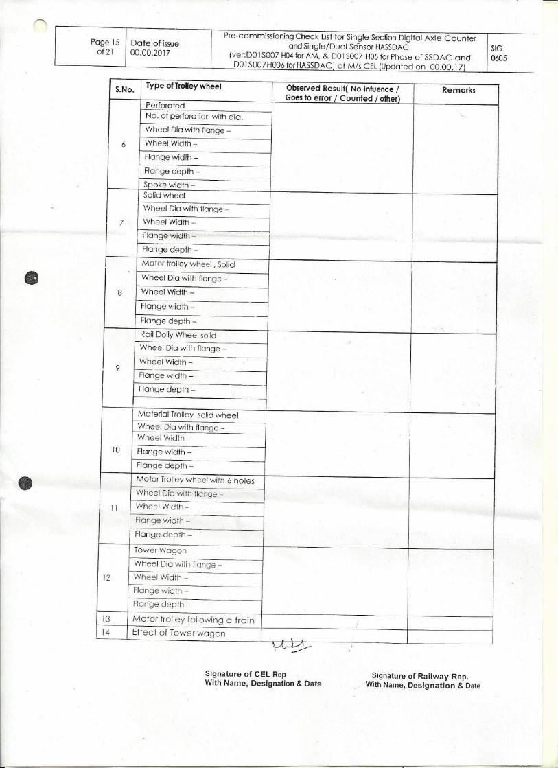
ii) The system counts the followingtrolleys:
a) Push trolley with perforated wheel; b) Dip lorry and c) Motor trolley.
b) Trolly with following parameters will be counted
A) Flange Height >28mm, B) Flange width> 15mm, C) Tyre base >110 mm.
Any variation in even one parameter of Push/Motor Trolley may lead the system to error.
Undetected Detected
2. Power Supply voltage required at input of system is 24V DC.
3. Resetting of axle counter only after registration of 1st
out count.
4. Surge Voltage Protection device SV-121 has been provided with additional protection module for
modem line for reset box.v.
S. No. Item Model No.
1.
2.
3.
4.
5.
SSDAC
Axle Detectors
Vital Relay Box with PR Relay
Reset Box
Surge Voltage Protection device
DACF – 710P
AD - 711
VR – 721
RB – 259
SV - 121
Please Note : - Kindly verify the version number of each card before its use and while ordering for spares in existing system. Based on the version number , feature may vary so you are requested to contact CEL for suitable guidance.For Modifying SSDAC version DACF-700A or DAC700AP to current model DACF-710A/P the following are required.
1. Replacement of Motherboard, MLB cards, Modem Card (AGC and above only).
2. Replacement of reset Box model - RB258 to model – RB259
3. Replacement of Surge Voltage Protection Device model from SV120 to SV121.
4. Additional pair of quad for displaying of packets information from location box to SM’s Room.
If all of the above modifications are carried out in each system, the features specified as per RDSO/SPN/177/2005 of DACF-710A/P will be available.
For Modifying Amplitude Model SSDAC to Phase Reversal Type SSDAC, the following are required
1. Replacement of Axle Detectors model AD-710 with AD-711.2. Modification of Signal Conditioner Cards 1 & 2
vi
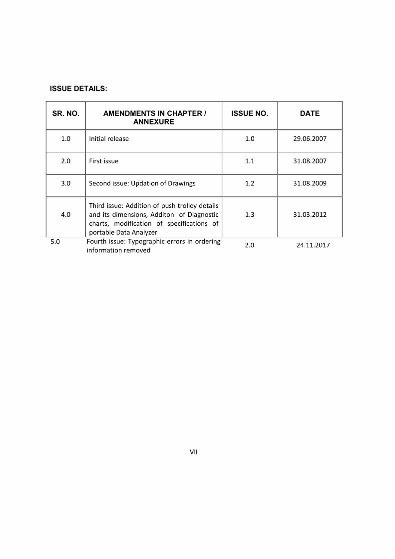
ISSUE DETAILS:
SR. NO. AMENDMENTS IN CHAPTER / ANNEXURE
ISSUE NO. DATE
1.0 Initial release 1.0 29.06.2007
2.0 First issue 1.1 31.08.2007
3.0 Second issue: Updation of Drawings 1.2 31.08.2009
4.0
Third issue: Addition of push trolley details
and its dimensions, Additon of Diagnostic
charts, modification of specifications of
portable Data Analyzer
1.3 31.03.2012
VII
5.0 Fourth issue: Typographic errors in ordering information removed
2.0 24.11.2017

viii
WARRANTY
At CEL, we understand the needs of Railways to provide reliable Signalling
systems. We have always strived to provide quality products to Railways.
CEL gives warranty for this product for 12 months from date of purchase by
the user against defects in material and workmanship. After expiry of this
period, you can still avail of the repair facility by paying for the same. The
warranty is subject to the following conditions
1. To provide the details of purchase date from CEL.
2. The defective card / unit must be delivered at the user's cost to service
centre in CEL.
3. The guarantee is not valid for the damages resulting from accidents,
mishandling, negligence, unauthorised repairs, tampering, loss of
components / accessories, exposure to extensive heat and temperature,
damped due to rain or any other chemical such as acid etc.
4. CEL’s liability for damages is restricted to repair/ replacement of the
defective parts.

OUR COMMITMENT
For more than 22 years CEL has harnessed the power of intellectual signalling
professionals to design and produce highly reliable products for Railway
Signalling Application. These include Universal Axle Counter, Block proving by
Axle Counter for Single and Double lines etc.
From the year 2000 CEL started working on innovative products based on
software and Micro controller technologies. We came up with Single Section
Digital Axle Counter conforming to CENELEC SIL-4 standard for track circuiting
and block proving application in Railways.
CEL has highly motivated professionals and specialists trained on the above
technologies. We reiterate and extend our commitment for modernisation of
signalling systems in railways. We are now manufacturing & supplying Single
Section Digital Axle Counters to Railways.
IX
x
IMPORTANT
Before Use
1. Please read all the instructions described in this manual carefully for proper installation of
SSDAC
2. After making connections to TX & Rx coils, check the presence of Rx coil signals, which
gives pulse output by means of LED glow on SCC1 & SCC2 cards. If not reverse the
connection of Rx coil cable.
3. The system has been provided with preparatory reset feature. In case of failure the reset
is to be applied by SM and the system comes to preparatory state. One train is to be
piloted in the section for system to become clear. Procedure for piloting should be
followed as per Station Working Rule in railways.
4. SSDAC and Reset Box are provided with sealing arrangement. The SSDAC top and back
covers are to be sealed. Reset Box in SM's Room is also to be sealed with metal seal. This
is to be done before commissioning at site.
For Best Performance
1. Provide battery and battery charger exclusively for this system. Do not add any other load
on this battery.
2. Maintain battery to provide steady 24V to the system. Check that no interruption takes
place on power supply.
3. Make sure to Switch off 24 V Power Supply to SSDAC before removing or reinserting the
card (spare) into the system.
4. Make sure that the system is connected to earth (1 Ohms) for protecting from lightning at
all locations of SSDAC.
5. Only twisted quad pair shall be used between two units for modem connection.
6. While resetting, Reset key and button shall not be pressed for more than 10 seconds. Ideal
time is 3 to 8 seconds

FOREWORD
Congratulations for your decision to purchase single section digital axle counter for
line / section verification to control and drive signals in Railways.
We assure you that the SSDAC opens new era of signalling system for providing track
circuiting and block working in Railways.
The contents of this manual have been divided into 18 chapters. The Installation
procedure, interconnections, measurements, commissioning, maintenance and
monitoring of system are described. The functions of SSDAC have been clearly
defined for better understanding and correct installation of system.
Chapter 1 to 3 System information
Chapter 4 & 5 specifies the System Installation procedure.
Chapter 6 gives Inter connection details
Chapter 7 is Measurement of signals.
Chapter 8 & 9 describes Communication & System software.
Chapter 10 describes LED indications and Error codes.
Chapter 11 is Earthing Instructions
Chapter 12 Surge Voltage & Lightning protection
Chapter 13 Resetting the system
Chapter 14 Commissioning of the system.
Chapter 15 is about Maintenance of system
Chapter 16 Tools & Spares
Chapter 17 Do’s & Don’ts
Chapter 18 Event logger recording & analysis
Author
Xi
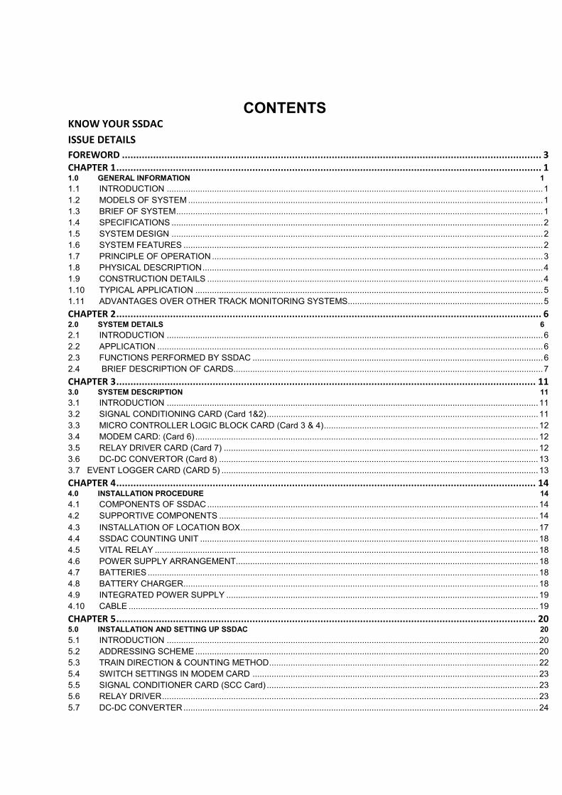
CONTENTS KNOW YOUR SSDAC
ISSUE DETAILS
FOREWORD .................................................................................................................................................... 3
CHAPTER 1 ...................................................................................................................................................... 1 1.0 GENERAL INFORMATION 1
1.1 INTRODUCTION .............................................................................................................................................................. 1 1.2 MODELS OF SYSTEM ..................................................................................................................................................... 1 1.3 BRIEF OF SYSTEM .......................................................................................................................................................... 1 1.4 SPECIFICATIONS ............................................................................................................................................................ 2 1.5 SYSTEM DESIGN ............................................................................................................................................................ 2 1.6 SYSTEM FEATURES ....................................................................................................................................................... 2 1.7 PRINCIPLE OF OPERATION ........................................................................................................................................... 3 1.8 PHYSICAL DESCRIPTION ............................................................................................................................................... 4 1.9 CONSTRUCTION DETAILS ............................................................................................................................................. 4 1.10 TYPICAL APPLICATION .................................................................................................................................................. 5 1.11 ADVANTAGES OVER OTHER TRACK MONITORING SYSTEMS.................................................................................. 5
CHAPTER 2 ...................................................................................................................................................... 6 2.0 SYSTEM DETAILS 6
2.1 INTRODUCTION .............................................................................................................................................................. 6 2.2 APPLICATION .................................................................................................................................................................. 6 2.3 FUNCTIONS PERFORMED BY SSDAC .......................................................................................................................... 6 2.4 BRIEF DESCRIPTION OF CARDS.................................................................................................................................. 7
CHAPTER 3 .................................................................................................................................................... 11 3.0 SYSTEM DESCRIPTION 11
3.1 INTRODUCTION ............................................................................................................................................................ 11 3.2 SIGNAL CONDITIONING CARD (Card 1&2) .................................................................................................................. 11 3.3 MICRO CONTROLLER LOGIC BLOCK CARD (Card 3 & 4) .......................................................................................... 12 3.4 MODEM CARD: (Card 6) ................................................................................................................................................ 12 3.5 RELAY DRIVER CARD (Card 7) .................................................................................................................................... 12 3.6 DC-DC CONVERTOR (Card 8) ...................................................................................................................................... 13 3.7 EVENT LOGGER CARD (CARD 5) ..................................................................................................................................... 13
CHAPTER 4 .................................................................................................................................................... 14 4.0 INSTALLATION PROCEDURE 14
4.1 COMPONENTS OF SSDAC ........................................................................................................................................... 14 4.2 SUPPORTIVE COMPONENTS ...................................................................................................................................... 14
4.3 INSTALLATION OF LOCATION BOX ............................................................................................................................. 17 4.4 SSDAC COUNTING UNIT .............................................................................................................................................. 18 4.5 VITAL RELAY ................................................................................................................................................................. 18 4.6 POWER SUPPLY ARRANGEMENT............................................................................................................................... 18 4.7 BATTERIES .................................................................................................................................................................... 18 4.8 BATTERY CHARGER..................................................................................................................................................... 18 4.9 INTEGRATED POWER SUPPLY ................................................................................................................................... 19 4.10 CABLE ............................................................................................................................................................................ 19
CHAPTER 5 .................................................................................................................................................... 20 5.0 INSTALLATION AND SETTING UP SSDAC 20
5.1 INTRODUCTION ............................................................................................................................................................ 20 5.2 ADDRESSING SCHEME ................................................................................................................................................ 20 5.3 TRAIN DIRECTION & COUNTING METHOD ................................................................................................................. 22 5.4 SWITCH SETTINGS IN MODEM CARD ........................................................................................................................ 23 5.5 SIGNAL CONDITIONER CARD (SCC Card) .................................................................................................................. 23 5.6 RELAY DRIVER .............................................................................................................................................................. 23 5.7 DC-DC CONVERTER ..................................................................................................................................................... 24
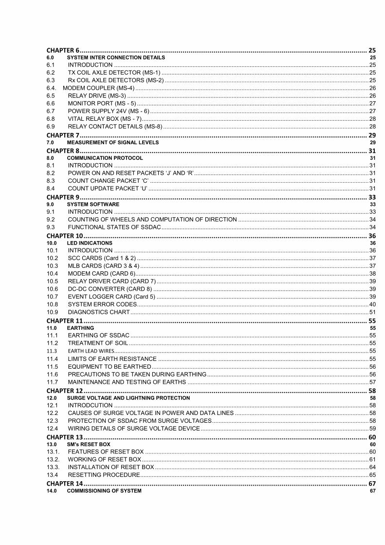
CHAPTER 6 .................................................................................................................................................... 25 6.0 SYSTEM INTER CONNECTION DETAILS 25
6.1 INTRODUCTION ............................................................................................................................................................ 25 6.2 TX COIL AXLE DETECTOR (MS-1) ............................................................................................................................... 25 6.3 Rx COIL AXLE DETECTORS (MS-2) ............................................................................................................................. 25 6.4. MODEM COUPLER (MS-4) ............................................................................................................................................... 26 6.5 RELAY DRIVE (MS-3) .................................................................................................................................................... 26 6.6 MONITOR PORT (MS - 5) .............................................................................................................................................. 27 6.7 POWER SUPPLY 24V (MS - 6) ...................................................................................................................................... 27 6.8 VITAL RELAY BOX (MS - 7) ........................................................................................................................................... 28 6.9 RELAY CONTACT DETAILS (MS-8) .............................................................................................................................. 28
CHAPTER 7 .................................................................................................................................................... 29 7.0 MEASUREMENT OF SIGNAL LEVELS 29
CHAPTER 8 .................................................................................................................................................... 31 8.0 COMMUNICATION PROTOCOL 31
8.1 INTRODUCTION ............................................................................................................................................................ 31 8.2 POWER ON AND RESET PACKETS ‘J’ AND ‘R’ ........................................................................................................... 31 8.3 COUNT CHANGE PACKET ‘C’ ...................................................................................................................................... 31 8.4 COUNT UPDATE PACKET ‘U’ ....................................................................................................................................... 31
CHAPTER 9 .................................................................................................................................................... 33 9.0 SYSTEM SOFTWARE 33
9.1 INTRODUCTION ............................................................................................................................................................ 33 9.2 COUNTING OF WHEELS AND COMPUTATION OF DIRECTION ................................................................................ 34 9.3 FUNCTIONAL STATES OF SSDAC ............................................................................................................................... 34
CHAPTER 10 .................................................................................................................................................. 36 10.0 LED INDICATIONS 36
10.1 INTRODUCTION ............................................................................................................................................................ 36 10.2 SCC CARDS (Card 1 & 2) .............................................................................................................................................. 37 10.3 MLB CARDS (CARD 3 & 4) ............................................................................................................................................ 37 10.4 MODEM CARD (CARD 6) ............................................................................................................................................... 38 10.5 RELAY DRIVER CARD (CARD 7) .................................................................................................................................. 39 10.6 DC-DC CONVERTER (CARD 8) .................................................................................................................................... 39 10.7 EVENT LOGGER CARD (Card 5) .................................................................................................................................. 39 10.8 SYSTEM ERROR CODES .............................................................................................................................................. 40 10.9 DIAGNOSTICS CHART .................................................................................................................................................. 51
CHAPTER 11 .................................................................................................................................................. 55 11.0 EARTHING 55
11.1 EARTHING OF SSDAC .................................................................................................................................................. 55 11.2 TREATMENT OF SOIL ................................................................................................................................................... 55 11.3 EARTH LEAD WIRES ............................................................................................................................................................ 55
11.4 LIMITS OF EARTH RESISTANCE ................................................................................................................................. 55 11.5 EQUIPMENT TO BE EARTHED ..................................................................................................................................... 56 11.6 PRECAUTIONS TO BE TAKEN DURING EARTHING ................................................................................................... 56 11.7 MAINTENANCE AND TESTING OF EARTHS ............................................................................................................... 57
CHAPTER 12 .................................................................................................................................................. 58 12.0 SURGE VOLTAGE AND LIGHTNING PROTECTION 58
12.1 INTRODCUTION ............................................................................................................................................................ 58 12.2 CAUSES OF SURGE VOLTAGE IN POWER AND DATA LINES .................................................................................. 58 12.3 PROTECTION OF SSDAC FROM SURGE VOLTAGES ................................................................................................ 58 12.4 WIRING DETAILS OF SURGE VOLTAGE DEVICE ....................................................................................................... 59
CHAPTER 13 .................................................................................................................................................. 60 13.0 SM's RESET BOX 60
13.1. FEATURES OF RESET BOX ......................................................................................................................................... 60 13.2. WORKING OF RESET BOX ........................................................................................................................................... 61 13.3. INSTALLATION OF RESET BOX ................................................................................................................................... 64 13.4 RESETTING PROCEDURE ............................................................................................................................................ 65
CHAPTER 14 .................................................................................................................................................. 67 14.0 COMMISSIONING OF SYSTEM 67
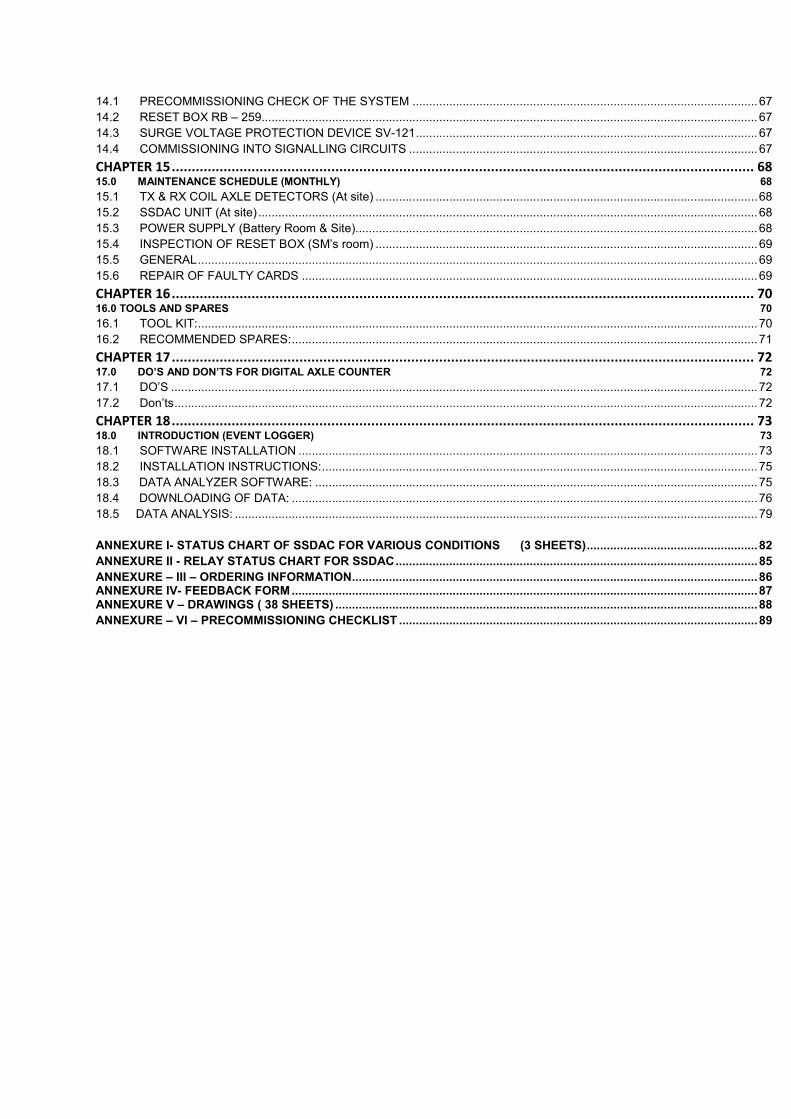
14.1 PRECOMMISSIONING CHECK OF THE SYSTEM ....................................................................................................... 67 14.2 RESET BOX RB – 259.................................................................................................................................................... 67 14.3 SURGE VOLTAGE PROTECTION DEVICE SV-121 ...................................................................................................... 67 14.4 COMMISSIONING INTO SIGNALLING CIRCUITS ........................................................................................................ 67
CHAPTER 15 .................................................................................................................................................. 68 15.0 MAINTENANCE SCHEDULE (MONTHLY) 68
15.1 TX & RX COIL AXLE DETECTORS (At site) .................................................................................................................. 68 15.2 SSDAC UNIT (At site) ..................................................................................................................................................... 68 15.3 POWER SUPPLY (Battery Room & Site) ........................................................................................................................ 68 15.4 INSPECTION OF RESET BOX (SM’s room) .................................................................................................................. 69 15.5 GENERAL ....................................................................................................................................................................... 69 15.6 REPAIR OF FAULTY CARDS ........................................................................................................................................ 69
CHAPTER 16 .................................................................................................................................................. 70 16.0 TOOLS AND SPARES 70
16.1 TOOL KIT: ....................................................................................................................................................................... 70 16.2 RECOMMENDED SPARES: ........................................................................................................................................... 71
CHAPTER 17 .................................................................................................................................................. 72 17.0 DO’S AND DON’TS FOR DIGITAL AXLE COUNTER 72
17.1 DO’S ............................................................................................................................................................................... 72 17.2 Don’ts .............................................................................................................................................................................. 72
CHAPTER 18 .................................................................................................................................................. 73 18.0 INTRODUCTION (EVENT LOGGER) 73
18.1 SOFTWARE INSTALLATION ......................................................................................................................................... 73 18.2 INSTALLATION INSTRUCTIONS: .................................................................................................................................. 75 18.3 DATA ANALYZER SOFTWARE: .................................................................................................................................... 75 18.4 DOWNLOADING OF DATA: ........................................................................................................................................... 76 18.5 DATA ANALYSIS: ............................................................................................................................................................ 79
ANNEXURE I- STATUS CHART OF SSDAC FOR VARIOUS CONDITIONS (3 SHEETS) ................................................... 82
ANNEXURE II - RELAY STATUS CHART FOR SSDAC ............................................................................................................ 85
ANNEXURE – III – ORDERING INFORMATION ......................................................................................................................... 86 ANNEXURE IV- FEEDBACK FORM ........................................................................................................................................... 87 ANNEXURE V – DRAWINGS ( 38 SHEETS) .............................................................................................................................. 88
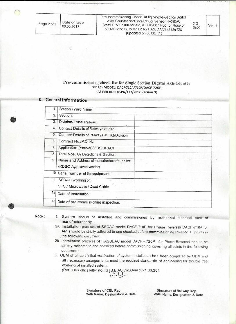
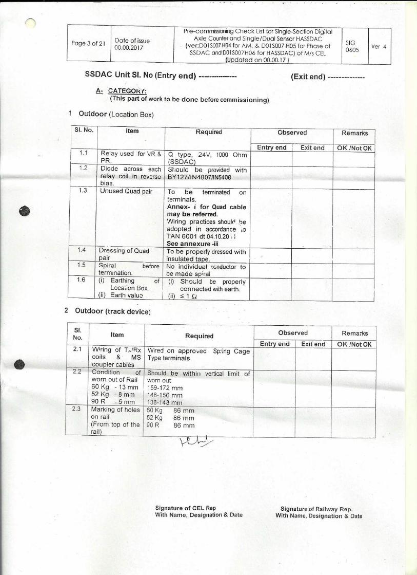
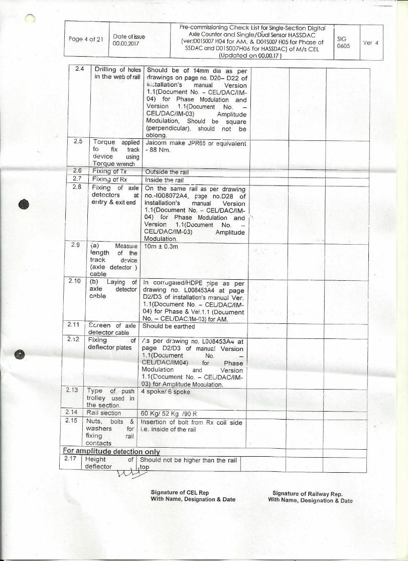
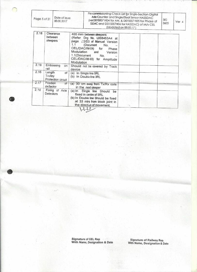
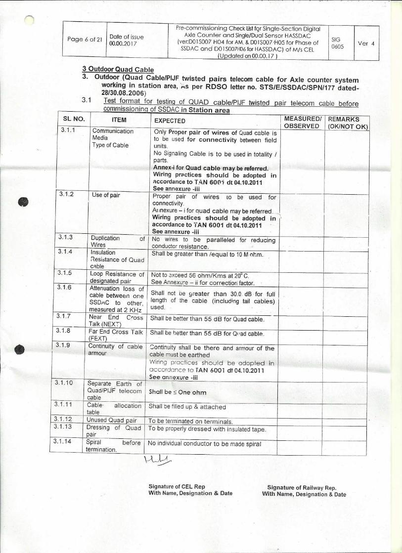
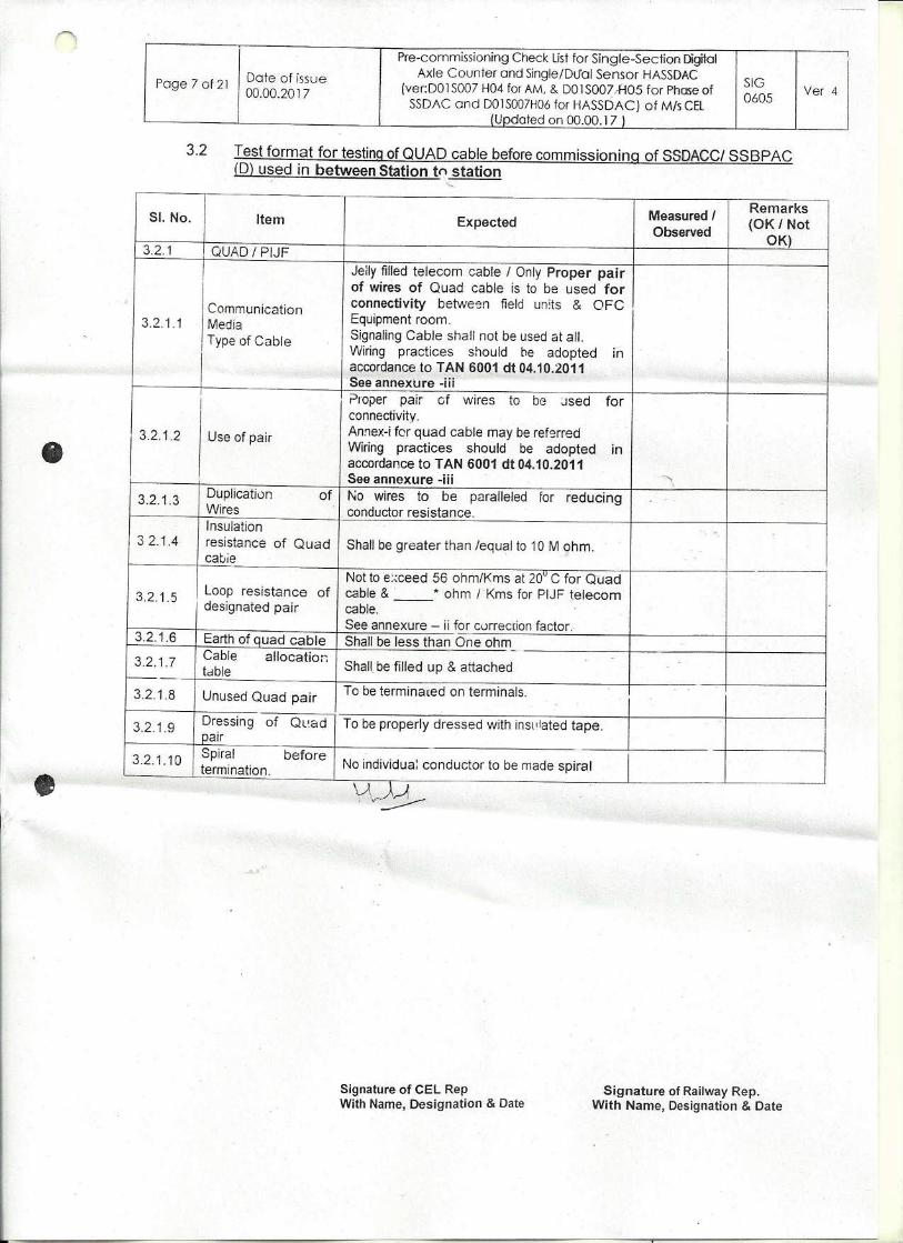
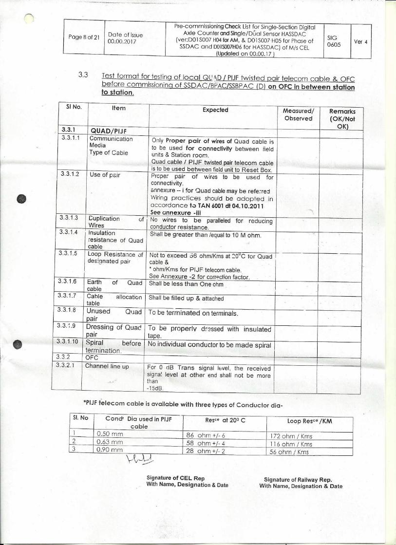
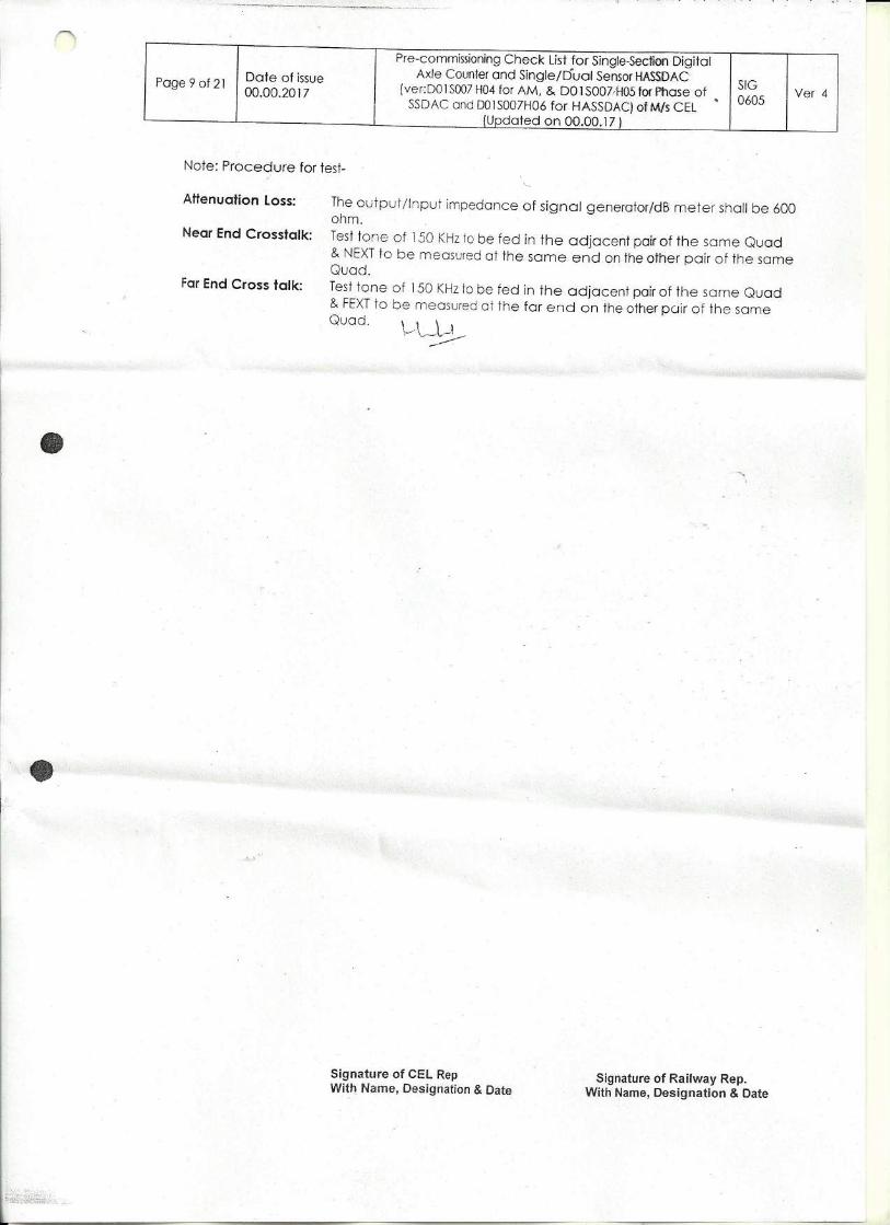
ANNEXURE – VI – PRECOMMISSIONING CHECKLIST ........................................................................................................... 89
1
CHAPTER 1
1.0 GENERAL INFORMATION
1.1 INTRODUCTION
Axle Counter is train detection equipment for use in Railways for monitoring a defined track
section to provide occupancy / clear status. The System detects the presence of a train in any
specified track section. The track section can be platform lines, yard lines, block section
between two stations.
The axle counters have been designed first with transistorized circuits and after that the
systems were made using ICs. Now CEL and RDSO have made an effort to design and develop
a Single Section Digital Axle Counter (SSDAC) using Micro Controller and software program.
The communication used in the system is by means of packets for exchange of information
between units. The communication is in duplex mode and is fail-safe. The Digital Axle Counter
model received by you is DACF-710P for monitoring single section.
1.2 MODELS OF SYSTEM
The Single Section Digital Axle Counter is manufactured and supplied in following model.
i. SSDAC for 2 Detection point DACF – 710P
ii. SSDAC for 2 Detection point DACF – 710A
The application of 2-Detection point system is for block section, platform lines, yard lines and
auto section.
1.3 BRIEF OF SYSTEM
The System consists of SSDAC units, TX/Rx coil Axle detectors and vital relays. The SSDAC Unit
is designed with High Frequency tuned circuits; pulse shaping circuits and Micro Controllers.
The system has been designed for installing on trackside at Outdoor. 2 units (one pair)
constitute one system for monitoring single-track section. The units are to be installed near
the trackside at the beginning and end of the track section i.e. outer limits of section. The
system is easy to install, Commission and maintain. The system is designed using Micro
controller along with other electronic circuits and programmed using dedicated software.
When any of these circuits fail, the system goes to fail-safe-condition. In case of failure in the
Single Section Digital Axle Counter the station master has to apply the reset and after that the
system goes to preparatory state. After which one pilot train has to be moved (piloted) in the
INSTALLATION MANUAL DACF-710P

2
section for system to become clear. This removes the dangers associated with system
becoming clear on direct traditional reset.
1.4 SPECIFICATIONS
The System has been designed to the RDSO Specification No: RDSO/SPN/177/2012.
1.5 SYSTEM DESIGN
The basic design of the system is based on counting the number of axles passing at each
detection point. These stored counts are transmitted to the second unit of the system and
vice versa by means of modem communication. The communication consists of digital packets
having details of counts, health and no error condition to arrive at the decision of clearance. If
counts registered at both detection points are equal, the section is cleared. Otherwise the
section is shown as occupied.
The design of the system is aimed at providing failsafe operation. The redundancy is built into
the system design by means of 2 out of 2 Micro Controller decision. This means two
computing elements are built in each system to check arrival and clearance of train from the
track section. The cards should be always in agreement for clearance of the section thereby
providing an authentic decision, otherwise goes to a fail-safe operation.
The Digital Axle Counter has two micro controllers and two separate data collection paths.
Both the micro controllers continuously communicate with each other to share respective
count information and to monitor each other’s health. The count information from both the
micro controllers is used to compute the final output.
The design of System consists of: -
a. 21 KHz & 23 KHz High frequency Axle detectors.
b. Micro controller based design with 2 out of 2 decision.
c. Counting through software.
d. Modem communication (2 wire).
e. Opto isolated vital relay drive.
f. Fail safe operation.
1.6 SYSTEM FEATURES
i. Trackside electronic counting equipment
ii. Web mounted type Axle Detectors
INSTALLATION MANUAL DACF-710P
3
iii. 4-spokes / 8-spokes push trolley wheel with wheel flange less than 22 mm and wheel base
less than 100 mm has no effect on the system (system remains NORMAL).The push trolleys
recommended for use with SSDAC is given in Drawing No – P008697 Page D34
iv. Compatible with 90R, 52 Kg & 60 Kg rail profiles
v. Easy to install, commission and maintain.
vi. Vital Relay output at both ends of the system.
The SSDAC model No – DACF-710 A/P supports the resetting of axle counter only on one
outcount. In this case the system will not accepts any resetting operation till outcount is
registered. The current model also supports the display of Error and Counts on the Reset
Box. For displaying the information one additional pair of quad cable is required from
location to station master’s reset panel.
1.7 PRINCIPLE OF OPERATION
The Digital Axle Counter System comprises of: -
i. Axle detectors AD 711
a. TX coils - 2 Nos.
b. RX coils - 2 Nos.
ii. SSDAC DACF 710P - 2 Nos.
iii. Vital Relay Box VR721- 2 Nos
iv. Reset Box RB 259 - 1 No. for common resetting (station area / platform)
- 2 Nos. for independent resetting
The Digital Axle Counter System works in combination of 2 units (1 pair) for one-track section.
One SSDAC Unit of the system is installed at each end of the track section along with one set
of TX and RX coil Axle detectors. The TX and RX coils are mounted on web of the rail at each
location. The system front end generates carrier signals that are fed to the rail mounted TX
coil Axle Detectors and receives these signals in Rx Coils at the respective location. When
wheels of the train pass over the detection point, the carrier signal is modulated by means of
phase reversal upto 180o in the Rx coils. The phase-modulated signal is compared with
standard reference signal and processed in the counting unit. The resultant signal is converted
into a wheel pulse. Each passing wheel generates a set of two pulses in quick succession i.e.
one after the other with some delay. This is shown in Drg. No L008077A3 (Page No D7) and Drg.
No.I007765A4 (Page No. D8).
INSTALLATION MANUAL DACF-710P
4
The SSDAC Unit monitors these wheel pulses A & B to detect the direction of movement of
train. It registers the counts of the number of wheels passing over the location and keeps the
total count. The first unit sends its count to the second unit located at the other end of the
track section at regular intervals. Similarly the first unit receives the count status from the
second unit of the system. Each unit of the system compares the self-count with the remote
count received from the other unit and evaluates the section status. The various supervisory
signals are also monitored and checked in the SSDAC unit. Each SSDAC unit of the system
drives its Vital Relay to energized condition (Pick up) at their location after verification of the
following:
i. The self-count and remote counts are matched and equal.
ii. The supervisory signals are normal at both locations.
The track section is shown as CLEAR when the Vital Relay is picked up. Otherwise the track
section is shown as OCCUPIED. The Vital Relay contacts can be used by the Railways at both
ends or at any one end as per requirement.
1.8 PHYSICAL DESCRIPTION
The SSDAC Unit of the Digital Axle Counter system is manufactured in a 3U height and 42T
width desktop enclosure. The system comprises of eight plug-in modules. All the cards are of
extended single Euro size (220mm x 100mm) that plugs into a motherboard in the sub rack.
Drawing no A007745A4 (Page No. D9) shows the front view of the system and the position of
PCBs. Drawing no I008442A4 (Page No. D10) shows the rear view of the system.
The cards must be inserted in the order of card 1 to 8 from left to right in the sub rack. The
various dimensions of the system are as follows.
• Width: 300.0 mm. (42 T)
• Height: 133.0 mm (3 U)
• Depth: 300.0 mm
1.9 CONSTRUCTION DETAILS
i. Web mounted axle detectors.
ii. Sub rack for SSDAC.
iii. Modular design of cards.
iv. Inter card shielding.
v. Motherboard for Inter Card Connections.
INSTALLATION MANUAL DACF-710P
5
1.10 TYPICAL APPLICATION
The SSDAC system can be used for monitoring single track section with 2 detection
points. Refer Drawing no B007743A4 (Page D1)
1.11 ADVANTAGES OVER OTHER TRACK MONITORING SYSTEMS
i. Eliminates the need for wooden sleepers.
ii. Monitors section length up to 18 KMs.
iii. Low power consumption. (2.0 A @ 24V DC for complete system)
iv. Cable requirement is ½ Quad.
v. Can also be used on OFC.
vi. Q type Vital Relay 24V, 1000 Ohm output at both locations.
vii. Trolley suppression track circuit is not required.
INSTALLATION MANUAL DACF-710P
6
CHAPTER 2
2.0 SYSTEM DETAILS
2.1 INTRODUCTION
The system comprises of trackside SSDAC units, which are installed near the detection points
of the railway track. The system implements the total function of Counting of train wheels and
its evaluation at both detection points. This includes
i. Phase reversal type TX and Rx coil Axle detectors.
ii. Generation of carrier signal.
iii. Demodulation of received signal.
iv. Pulse Shaping and Validation.
v. Pulse Counting.
vi. Transmission and Reception of Counts between two units of SSDAC.
vii. Output for Vital Relay.
viii. Read Back of Vital Relay
2.2 APPLICATION
The SSDAC - 2D can be used for track circuiting in loop lines, block sections etc.
The SSDAC operates in Independent Mode without central evaluator. In this mode 2 numbers
of SSDAC Units are used. The 1st
unit of SSDAC transmits its wheel count to 2nd
unit of SSDAC
and also receives the wheel count from 2nd
unit of SSDAC. Based on its internally counted
wheel and the wheel count received from second unit of SSDAC, the SSDAC computes the
status of the corresponding track section and outputs the same to the relay port. The
communication between SSDAC’s is through a 2 Wire internal modem.
2.3 FUNCTIONS PERFORMED BY SSDAC
The various functions performed by SSDAC Counting unit are described below.
2.3.1 TX AND RX COIL AXLE DETECTORS
Each detection point comprise of 1 no. of Transmitter coil and 1 no. of Receiver coil. The
SSDAC generates 21 KHz & 23 KHz carrier signals to the Transmitter coils respectively. These
signals are received in Receiver coils. The receiver signal is phase modulated with each train
wheel passing over the detection point.
INSTALLATION MANUAL DACF-710P
7
2.3.2 Demodulation of Received Signal
When the train wheels passes over the detection point, the receive signal gets
modulated. The modulated receive signal is demodulated in the signal conditioner
card to generate pulses corresponding to wheels passing over the detection point.
2.3.3 Pulse Shaping and Validation
The generated set of A & B pulses corresponding to the wheels passing over the
detection points are passed through time filters and validated for acceptance.
2.3.4 Pulse Counting
The set of A & B pulses validated are used to identify the direction of movement of
train thereby to increment or decrement pulse counts. These counts identify the
number of wheels moving into or out of the section through that particular detection
point.
2.3.5 Transmission and Reception of Counts between the two units of SSDAC
In Independent mode of operation, 1st
unit of SSDAC periodically sends its wheel
counts to the second unit of SSDAC. Similarly, the 1st
unit of SSDAC receives wheel
counts from 2nd
unit of SSDAC. The counts from both units are compared to compute
the Clear/Occupied condition of the respective track section.
2.3.6 Vital Relay Drive:
If the counts compared between SSDAC are matched and equal, then the vital relay is
driven to Pick Up by the Relay Driver card.
2.3.7 Vital Relay Read Back:
The Vital Relay potential free contacts are fed with voltages and these are read back in
the system to check the vital relay is driven to pick up or drop as per the command
given from the system.
2.4 BRIEF DESCRIPTION OF CARDS
The block diagram of the SSDAC is given in Drawing no B007744A4 (Page No. D6). The
SSDAC comprises of following functional card modules. The SSDAC system is based on
2-out-of-2 Micro Controller architecture. Both the Micro Controller cards receive the
wheel pulses from the signal conditioner cards. The wheel counts are counted
independently. Each of the two Micro Controllers receives the wheel count from the
remote Axle Counter system and computes the track status independently. Both the
Micro Controller cards give the command for relay driving the vital relay. If both the
INSTALLATION MANUAL DACF-710P
8
Micro Controller agrees on count status and health, the Vital Relay is driven to pick up
otherwise it remains dropped. Each unit of SSDAC consists of following modules.
These modules implement the functions described in section 2.1.
i. Signal Conditioner Cards
a Carrier Signal Generation
b Demodulation and Pulse generation.
(Card 1 & 2)
ii. Micro controller logic blocks (2 micro controllers)
a. Pulse counting.
b. 2 out of 2 decision
c. Vital Relay Command Read back
d. Preparatory Relay Drive Command
(Card 3&4)
iii. Event Logger Card (for monitoring failures, etc)
a. For storage of events in the system.
(Card 5)
iv. Modem Card
a. Serial I/O Multiplexer
b. Resetting Circuit
(Card 6)
v. Relay Driver Card
a. Output drive for vital relay & PR Relay
(Card 7)
vi. Power Supply Module (DC-DC converter)
a. All the supply voltages required in SSDAC are generated
(Card 8)
All the above cards are of extended single Euro size (220mm x 100mm), which plugs into
a motherboard in the sub rack. The cards must be inserted from card 1 to 8 starting from
left within the sub rack.
2.4.1 SIGNAL CONDITIONER CARD (SCC) (Card 1 & 2)
2.4.1.1 Carrier Signal Generation
Each card generates the carrier signals, which is transmitted, to its transmitter coil
mounted on each detection point.
SCC1 (21 KHz) to TX Coil A.
SCC2 (23 KHz) to TX Coil B.
2.4.1.2 Demodulation and Pulse generation
Each card demodulates its receiver signal from Rx coil A & B to generate pulses
corresponding to wheels passing over the detection point. These pulses are then
validated and fed to Micro Controller Logic Cards.
Rx Coil A to SCC1 (21 KHz).
INSTALLATION MANUAL DACF-710P
9
Rx Coil B to SCC2 (23 KHz).
2.4.2 MICRO-CONTROLLER LOGIC BLOCK CARD (MLB) (Card 3&4)
The Micro Controller logic block cards are the heart of the unit. Two identical cards have been
implemented to give 2-out-of-2 decision. These cards perform the functions related to
counting of pulses, count validation, communication through Modem with 2nd Unit of SSDAC
and decision making to give output. The input pulses are given to both the Micro Controller
Logic Blocks. Both the micro-controller cards continuously monitor each other’s health and
wheel counts. If the results are not matching then the system goes into Error state.
The results of count check and health between 2 micro controller cards are always match to
arrive at a clear decision by the system.
Vital relay read back feature is included in the Micro controller card to read back the vital
relay in occupied as well as in the clear state and checks as per the decision given from the
card.
2.4.3 MODEM CARD (Card 6)
V.21 Modem is used for communication between two units of SSDAC. The digital packets
generated by MLB cards are sent to remote unit on a pair of cable. Serial I/O Multiplexer is
used to select the micro controller card that will communicate with the modem on the remote
unit.
The SSDAC reset circuit is included in the modem card wherein the reset voltage window (36V
to 52V) and reset timing window (between 2 secs to 10 secs) functions has been provided. The
reset command will not respond for the cases outside these windows.
2.4.4 RELAY DRIVER CARD (Card 7)
The card module checks & generates the vital relay drive output to finally clear/occupied
status of the corresponding track section. The output is used to drive fail-safe vital relay.
2.4.5 DC-DC CONVERTER CARD (Card 8)
The Card receives 24V battery input and generates 5V, 12V, and 24V output with common
ground for all circuit requirements. A separate 15V with ISO ground is also provided for vital
Relay drive output.
2.4.6 EVENT LOGGER CARD (Card 5)
Event Logger card is designed to capture and store important signals from the remote and
local SSDAC units. The stored data can be downloaded from the event logger card for the
INSTALLATION MANUAL DACF-710P

10
purpose of analyzing the events occurring during the operations of the SSDAC. The data can
be analyzed with the help of CEL Data analyzer software.
INSTALLATION MANUAL DACF-710P
11
CHAPTER 3
3.0 SYSTEM DESCRIPTION
3.1 INTRODUCTION
The SSDAC Counting Unit comprises of the following cards.
i. Signal Conditioning Card Card 1 & 2 2 Nos.
ii. Micro Controller Logic Card 3 & 4 2 Nos.
iii. Event Logger Card 5 1 No.
iv. Modem Card 6 1 No.
v. Relay Driver Card 7 1 No
vi. DC-DC converter Card 8 1 No.
----------
Total: 8 Nos.
-----------
The card details are described in following sections.
3.2 SIGNAL CONDITIONING CARD (Card 1&2)
The Signal Conditioning Cards (SCC) generates high frequency (SCC1-21 KHz, SCC2-23 KHz)
carrier signals, which are transmitted to the two independent TX coils of axle detectors. The
two independent Rx coils receive these signals, which are at a phase difference upto 180o with
respect to reference signal of TX coils. The TX and Rx coils are mounted to the web of rails.
When the train wheels passes over the axle detectors, the Rx signal phase difference becomes
nearly to zero with respect to reference signal of TX coils. The SCC card processes the change
of phase difference from 180o to 0
o between the reference & Rx coil signals and converts it
into valid train pulses. The supervisory levels are also generated. The board generates TTL
compatible pulse and supervisory signals. The Oscillator, Pulse & Supervisory OK signal
indications are provided on the card. The SSDAC system with phase reversal type track devices
does not require short length DC track circuits (3 Rail Length.) and its TPR relay connections
for trolley suppression.
INSTALLATION MANUAL DACF-710P
12
3.3 MICRO CONTROLLER LOGIC BLOCK CARD (Card 3 & 4)
The Micro controller Logic Block Card (MLB) is the heart of the system. These cards implement
the wheel detection, train direction checking and wheel counting functions. In addition it
receives the remote wheel count and computes the status of the section for clear or occupied.
It also Checks various supervisory signal levels like supervisory of TX/Rx coils, presence of
various cards, LED check, communication link failure etc.
The card design is based on 8051 compatible micro controllers. The salient features of the
card are as follows: -
i. Micro controller is based on industry standard 89C51
ii. RS232C compatible serial port for modem connectivity
iii. 10K byte on chip Flash ROM for program storage
iv. 256 byte on chip RAM
v. Parallel ports for address/mode input, pulse inputs and Vital Relay output and relay
read back.
vi. Extensive LED display – A block of 8 LED indicators for count progress / error display, 2
independent LED indicators for section status.
3.4 MODEM CARD: (Card 6)
The Modem card being used is of V.21 type (2 wires) in Single Section Digital Axle Counter
(SSDAC). The card interfaces with serial RS232C port of both Micro controller Logic Block
cards. It multiplexes the two RS232 inputs and selects one of the two channels and provides
signal conversion from digital to analog and vice-versa as per CCITT V.21 standard. The board
uses OKI FSK modem IC.
i. The Salient features of the card include: -FSK Full Duplex modem chip
ii. V.21 mode of operation ( 2 wire )
iii. 300 Baud rate
iv. Multiplexes the two serial ports
v. Originator (Entry unit) and Answerer (Exit unit) for V21 selected.
vi. Automatic gain controls provided in receive path.
vii. SSDAC reset circuit including the reset voltage window and reset timing window
function.
3.5 RELAY DRIVER CARD (Card 7)
The Relay Driver card (RD) is the output card for driving Vital Relay for Single Section Digital
Axle Counter (SSDAC). The card is of extended Euro size card terminated with 64 pin standard
INSTALLATION MANUAL DACF-710P
13
Euro Connector. The card directly plugs into the motherboard of SSDAC. One RD card is used
in each SSDAC counting unit. The Relay Driver card receives the command of clear and clock
signals from MLB1 & MLB2 cards and drives the vital relay to energized condition (Pick up)
when section is clear. If a train occupies the section, the vital relay is dropped. The command
signals and vital relay Pick up is indicated on the card. The preparatory reset output after
system becomes normal after reset is driven from this card.
The main functions of the card are:
i. Dual Clock Checking circuits
ii. Opto isolator Circuit.
iii. Vital Relay Drive Output.
iv. Preparatory Reset (PR) Relay drive output.
3.6 DC-DC CONVERTOR (Card 8)
The DC-DC Converter card converts 24Vdc input to different DC Power supply required by the
SSDAC in an extended Euro size board that is plugged directly in to the SSDAC motherboard.
The main features of the board are: -
i. Low Ripple
ii. Wide input line regulation
iii. Very good load regulation
iv. Input/output protected for short circuit.
v. Immune to EMI/RFI Interference.
3.7 EVENT LOGGER CARD (CARD 5)
Please refer chapter 18 for details.
INSTALLATION MANUAL DACF-710P
14
CHAPTER 4
4.0 INSTALLATION PROCEDURE
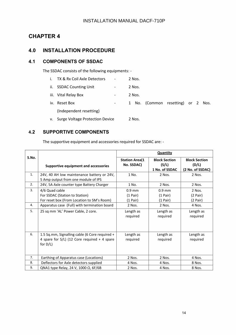
4.1 COMPONENTS OF SSDAC
The SSDAC consists of the following equipments: -
i. TX & Rx Coil Axle Detectors - 2 Nos.
ii. SSDAC Counting Unit - 2 Nos.
iii. Vital Relay Box - 2 Nos.
iv. Reset Box - 1 No. (Common resetting) or 2 Nos.
(Independent resetting)
v. Surge Voltage Protection Device 2 Nos.
4.2 SUPPORTIVE COMPONENTS
The supportive equipment and accessories required for SSDAC are: -
S.No.
Supportive equipment and accessories
Quantity
Station Area(1
No. SSDAC)
Block Section
(S/L)
1 No. of SSDAC
Block Section
(D/L)
(2 No. of SSDAC)
1. 24V, 40 AH low maintenance battery or 24V,
5 Amp output from one module of IPS
1 No. 2 Nos. 2 Nos.
2. 24V, 5A Axle counter type Battery Charger 1 No. 2 Nos. 2 Nos.
3. 4/6 Quad cable
For SSDAC (Station to Station)
For reset box (From Location to SM’s Room)
0.9 mm
(1 Pair)
(1 Pair)
0.9 mm
(1 Pair)
(1 Pair)
2 Nos.
(2 Pair)
(2 Pair)
4. Apparatus case (Full) with termination board 2 Nos. 2 Nos. 4 Nos.
5. 25 sq mm ‘AL’ Power Cable, 2 core. Length as
required
Length as
required
Length as
required
6. 1.5 Sq.mm, Signalling cable (6 Core required +
4 spare for S/L) (12 Core required + 4 spare
for D/L)
Length as
required
Length as
required
Length as
required
7. Earthing of Apparatus case (Locations) 2 Nos. 2 Nos. 4 Nos.
8. Deflectors for Axle detectors supplied 4 Nos. 4 Nos. 8 Nos.
9. QNA1 type Relay, 24 V, 1000 Ω, 6F/6B 2 Nos. 4 Nos. 8 Nos.
INSTALLATION MANUAL DACF-710P
15
INSTALLATION MANUAL DACF-710P
The axle detector unit consists of:
i. Web Type Transmitter Coils (TX coil)
ii. Web Type Receiver Coils (Rx coil)
iii. Rail Deflector Bracket Assembly
4.2.1 DETAILS FOR FIXING OF AXLE DETECTORS i. The Axle detectors should be installed after Advance starter (LSS) signal post and Home (HS)
signal post on UP and DN lines of Double line section for use in BPAC.
ii. The Axle detectors should be installed after Advance Starter Signal (LSS) Post for UP & DN
Lines of Single Line Section for use in BPACs.
iii. In main Lines, loop lines, yard area the Axle detectors can be fixed just after the starter signal
post of each line under monitoring of SSDAC.
iv. The Axle detectors separation between two sets of different SSDAC systems should be at
least 2 meters away so as to avoid mutual interference.
v. The detectors have to be fixed on the clear spacing between two sleepers.
vi. It should be ensured that the rail is not badly worn out causing the wheel flanges to graze
over the fittings.
vii. The design of the detector is suitable for 90R, 52Kg and 60Kg rails.
viii. The transmitter and Receiver coils are provided with 24/0.2 shielded cables of 10m lengths
and have to be taken to location box directly without any loops.
ix. Transmitter and Receiver cables should run separately at a minimum separation of 400mm in
different HDPE pipes. The cables have to be laid in the 40mm HDPE pipe for safety and
buried underground below ballast at the depth of approx. 0.3mts.
4.2.2 PROCEDURE FOR FIXING OF AXLE DETECTORS 4.2.2.1 MARKING & DRILLING HOLES ON WEB OF RAIL
i. The marking jig is to be fixed from top of the rail and tightened to the rail with clamp.
ii. The marking for 3 holes with punch is to be made on the Web of rail using marking jig (Drg
No. F008300 on page D29 & D29a).
iii. The marking for 3 holes is given at a distance of 0 - 170 - 340mm.
iv. For 90 R or 90Lb, 52 Kg & 60Kg mark is 86mm from top.
16
v. The drilling is to be carried out on the web of rail at marked places by using drill machine/
ratchet drill method. 3 Nos. of holes of 14 mm dia are made on the web as per the
markings.
vi. The burr is to be removed from the holes after drilling is over.
IMPORTANT: The marking and drilling of holes on the web to the dimensions given are very
important for proper working of the system.
4.2.2.2 FIXING OF AXLE DETECTORS (TRANSMITTER AND RECEIVER COIL)
(Drg No. A008446A3 on page D20, A008447A3 on page D21, A008448A3 on page
D22)
i. The Axle detectors are to be fixed on web of the rail at the drilled holes by means
of M12 bolts & nuts with spring washers and check nuts. (NOTE: the torque
wrench, specified in the checklist, should be used for tightening of nuts and bolts.)
ii. M12 x 100mm - 3 Nos. bolts & nuts are used for fixing the axle detectors. 2nd
nut is
with Nylon washer and is to be used on each bolt.
iii. Transmitter coil assembly (21 KHz & 23 KHz) should be fixed on the outer side of
rail. The transmitter assembly should sit properly on the web of rail.
iv. Receiver coil assembly (21 KHz & 23 KHz) should be fixed on the inner side of rail.
The receiver assembly should be placed properly on the web of rail.
v. It should be ensured that transmitter coil assembly and receiver coil assembly are
facing opposite to each other (21 KHz TX to 21 KHz Rx and 23 KHz TX to 23 KHz Rx)
on either side of rail with centre line of coils matching each other.
vi. The TX coil cables 21 KHz & 23 KHz are taken together in one HDPE pipe to the
location Box. Similarly both 21 KHz & 23 KHz Rx coils are taken together but
separately from TX coil cables to the location box.
vii. The 1st
set of Transmitter and Receiver Coils is made of 21 KHz signal and 2nd
set is
made of 23 KHz signal at each Location.
Very Important
viii. Both at the Entry & Exit of the section, the axle detectors should be fixed on same
rail i.e. either on left side or on right side rail of the track. This should not be
installed with 1st
set on left rail and 2nd
set on right rail of the track at Entry & Exit
of the section. The Drawing no I008072A4 (Page No. D28) is to be followed for correct
installation of axle detector.
INSTALLATION MANUAL DACF-710P
17
Note: If it is installed on alternate rails of the track, the counting will not match and the
system will not function normally for train movement.
4.2.3 FIXING OF RAIL DEFLECTOR
i. To protect axle detectors against the damage from hanging parts of train, rail
deflector plates (protectors) should be mounted on both sides of the axle detectors.
These should be installed in the sleeper space (approx 30 cm to 40 cm next to the
axle detectors). The deflector clamps are first fixed to bottom of rail. These deflector
plates are fitted to deflector clamp with bolts and nuts on each side.
ii. While fixing deflector plates, it should be ensured that the deflector plates are positioned in
front of transmitter and receiver coil.
4.3 INSTALLATION OF LOCATION BOX
4.3.1 LOCATION BOX (Full size)
i. The location box should be installed as close as possible to detection point so that the
length of Axle detector cable should not exceed 10m.
ii. The location box foundation should be cast at rail level and as per scheduled dimensions of
Railways. (Standard practice in railways).
iii. One Shelf should be provided in the location box for keeping SSDAC Counting Unit & Vital
Relay Box.
iv. The VR box consists of Dual relay i.e. VR & PR relay of Q Type, 24V and 1000Ω type hence
no external relay is required in the location box. The available contacts from the relay can
be extended to the station for the external circuits for PR & VR. Refer Drawing no
S008429A3 (page no D18 & D19)
4.3.2 TERMINAL BOARD
i. The incoming and outgoing cables from the Axle detectors, SSDAC unit, modem and cable
going to the remote SSDAC is terminated on a cable termination board inside the location
box. It should also have the facility for measuring various parameters.
ii. The incoming and outgoing cables are terminated on spring cage type connectors from M/s
WAGO or M/s Phoenix fitted on DIN rail fitted on Bakelite sheet of location box. The cables
from SSDAC, power supply; TX and RX coils are to be terminated as per detail shown in
Drawing no W008474A3 (page no D13) & I008477A3 (page no D11). Fuse with rating of 2A is to
be provided on 24V Power Supply to the system.
INSTALLATION MANUAL DACF-710P
18
4.4 SSDAC COUNTING UNIT
The SSDAC is installed on the wooden/ Hylam /NFTC plank inside the location box. This is
firmly fixed using clamps, nuts & bolts. Refer Drawing no I008477A3 (Page no. D11)
4.5 VITAL RELAY
The VR Box is to be installed on the same wooden/Hylam/NFTC plank inside the location box
where SSDAC unit has been installed. The VR Box is also firmly fixed using clamps, nuts &
bolts. Refer Drawing no I008477A3 (Page no. D11). VR Box also has yellow colour LED and it will
glow when PR relay is picked up. The PR relay contacts can be extended to relay room for
proving PPR relay.
4.6 POWER SUPPLY ARRANGEMENT
The power supply to SSDAC consists of
i) 24V, 40 AH Battery and 24V, 5A Battery charger or 24V, 5A dedicated module of IPS.
ii) Power cable for connection from battery to SSDAC unit
The power supply and its equipments for digital axle counter are shown in Drawing no
S008429A3 (Page No. D18). Only Axle counter type battery charger should be used. When
integrated Power Supply (IPS) of 24V, 5 A is used, its ripple content should be within limits.
The same 24V Battery can be used for advance and home location of UP & DN SSDAC units of
double line block section.
This power supply should not be used for any other signaling gear/systems.
4.7 BATTERIES
The 24V, 40 AH low Maintenance Battery (12 VX 2Nos.) or 24V; 40AH Battery Bank may be
used for powering the two units of SSDAC. The batteries are to be procured as per latest RDSO
specifications.
i. The batteries are kept on teak wood/ hard wood shelf on MS angles and are to be
installed in the battery room.
ii. Insulators are to be provided below the batteries.
iii. The charging of batteries has to be done as per manufacturer’s manual.
4.8 BATTERY CHARGER
i. The Axle counter type Battery Charger as per latest specification is to be procured and
installed in the equipment room. The battery chargers are usually kept on teak wood shelf
fixed on MS Angles.
INSTALLATION MANUAL DACF-710P
19
ii. The 24V, 5A battery charger has to be installed and connected to battery on auto mode.
The current consumption of each SSDAC unit is 1.0A @ 24V. For complete system (2
SSDAC units) it is 2.0A @ 24V.
4.9 INTEGRATED POWER SUPPLY
The 24V, 5A output from one of the modules of Integrated Power Supply (IPS) of approved
manufactures may be used to power SSDAC units instead of Battery.
4.10 CABLE
The connecting cable from Battery / IPS to SSDAC units at the site should be as given below:
i. 2 core, 25 sq. mm aluminium power cable.
ii. 12+4 spare conductors (double line) or 6+4 spare conductors (single line) of 1.5 sq. mm
signalling cable
iii. 4/6 Quad cable (1 Quad for double line or ½ quad for single line for station to station
communication and 1 Quad for location to SM’s Room for reset display)
INSTALLATION MANUAL DACF-710P
20
CHAPTER 5
5.0 INSTALLATION AND SETTING UP SSDAC
5.1 INTRODUCTION
This chapter provides necessary information for installation of SSDAC. This includes addressing
scheme, and it’s setting through 8-way dip switch, modem setting, etc.
5.2 ADDRESSING SCHEME
The SSDAC can be used in single sections of all type with 2 detection points (2D)
The Counting Units of SSDAC communicate with each other on regular basis and provides the
status and wheel count to each other. The Evaluation and final decision for driving the vital
relay to pickup is also built in the SSDAC units. The SSDAC system for 2D, therefore, monitors
and provides the track clear/occupancy status of the section.
2D system for Single Section (Refer Drawing no B007743A4, Page No. D1)
The 2D system is designed by means of one pair i.e. 2 SSDAC units. The units are manufactured
as Entry and Exit end units for single section. The Entry unit is to be installed at the beginning
of a section i.e. Adv. starter and the Exit unit is to be installed at the end of a section i.e. Home
of a block section. The units are connected to Axle detectors, vital relay, Reset Box and other
wiring as per the wiring diagram Drawing no L008453A4, Page No. D2 & D3
The SSDAC units are provided with unique address schemes for selection of 15 different pairs
of units by means of 8-way dip switch on motherboard. We have selected the first pair in
factory and units are supplied. However, for providing different pairs of units in station area/
Block section, the address scheme is given in Table 5.1. The user can also monitor the address
of SSDAC units using monitor port (as explained in Chapter 17)
Caution: The SSDAC units installed for a single section should not be either both Entry type
or units installed should not be both Exit type for 2 D section. This may result in continuous
configuration Error in the system. The Entry and Exit unit markings have been printed on the
units for easy identification of the system. For avoiding wrong installation it is advised that
the same serial no units should be installed for one section.
INSTALLATION MANUAL DACF-710P
21
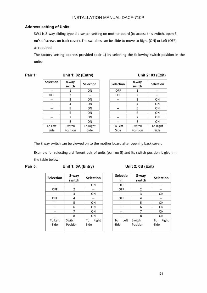
Address setting of Units:
SW1 is 8-way sliding type dip switch setting on mother board (to access this switch, open 6
no’s of screws on back cover). The switches can be slide to move to Right (ON) or Left (OFF)
as required.
The factory setting address provided (pair 1) by selecting the following switch position in the
units:
Pair 1: Unit 1: 02 (Entry) Unit 2: 03 (Exit)
Selection 8-way
switch Selection Selection
8-way
switch Selection
-- 1 ON OFF 1 --
OFF 2 -- OFF 2 --
-- 3 ON -- 3 ON
-- 4 ON -- 4 ON
-- 5 ON -- 5 ON
-- 6 ON -- 6 ON
-- 7 ON -- 7 ON
-- 8 ON -- 8 ON
To Left
Side
Switch
Position
To Right
Side
To Left
Side
Switch
Position
To Right
Side
The 8 way switch can be viewed on to the mother board after opening back cover.
Example for selecting a different pair of units (pair no 5) and its switch position is given in
the table below:
Pair 5: Unit 1: 0A (Entry) Unit 2: 0B (Exit)
Selection 8-way
switch Selection
Selectio
n
8-way
switch Selection
-- 1 ON OFF 1 --
OFF 2 -- OFF 2 --
-- 3 ON -- 3 ON
OFF 4 -- OFF 4 --
-- 5 ON -- 5 ON
-- 6 ON -- 6 ON
-- 7 ON -- 7 ON
-- 8 ON -- 8 ON
To Left
Side
Switch
Position
To Right
Side
To Left
Side
Switch
Position
To Right
Side
INSTALLATION MANUAL DACF-710P
22
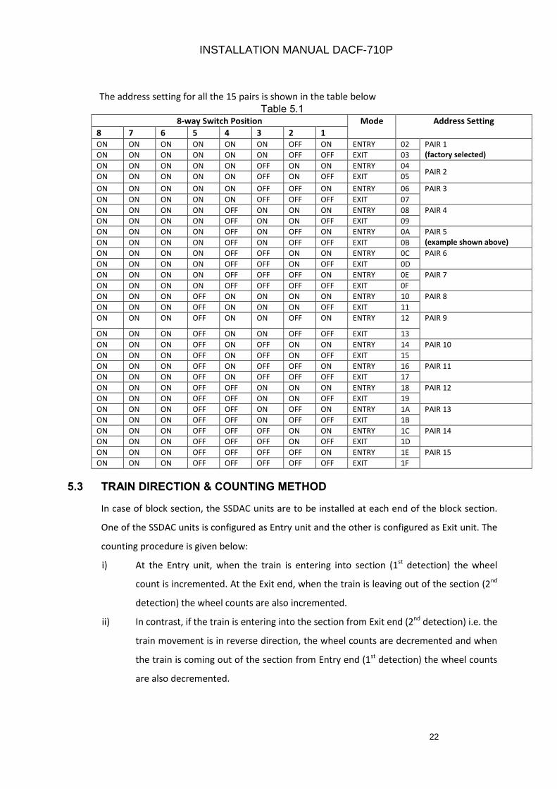
The address setting for all the 15 pairs is shown in the table below
Table 5.1 8-way Switch Position Mode Address Setting
8 7 6 5 4 3 2 1
ON ON ON ON ON ON OFF ON ENTRY 02 PAIR 1
(factory selected) ON ON ON ON ON ON OFF OFF EXIT 03
ON ON ON ON ON OFF ON ON ENTRY 04 PAIR 2
ON ON ON ON ON OFF ON OFF EXIT 05
ON ON ON ON ON OFF OFF ON ENTRY 06 PAIR 3
ON ON ON ON ON OFF OFF OFF EXIT 07
ON ON ON ON OFF ON ON ON ENTRY 08 PAIR 4
ON ON ON ON OFF ON ON OFF EXIT 09
ON ON ON ON OFF ON OFF ON ENTRY 0A PAIR 5
(example shown above) ON ON ON ON OFF ON OFF OFF EXIT 0B
ON ON ON ON OFF OFF ON ON ENTRY 0C PAIR 6
ON ON ON ON OFF OFF ON OFF EXIT 0D
ON ON ON ON OFF OFF OFF ON ENTRY 0E PAIR 7
ON ON ON ON OFF OFF OFF OFF EXIT 0F
ON ON ON OFF ON ON ON ON ENTRY 10 PAIR 8
ON ON ON OFF ON ON ON OFF EXIT 11
ON ON ON OFF ON ON OFF ON ENTRY 12 PAIR 9
ON ON ON OFF ON ON OFF OFF EXIT 13
ON ON ON OFF ON OFF ON ON ENTRY 14 PAIR 10
ON ON ON OFF ON OFF ON OFF EXIT 15
ON ON ON OFF ON OFF OFF ON ENTRY 16 PAIR 11
ON ON ON OFF ON OFF OFF OFF EXIT 17
ON ON ON OFF OFF ON ON ON ENTRY 18 PAIR 12
ON ON ON OFF OFF ON ON OFF EXIT 19
ON ON ON OFF OFF ON OFF ON ENTRY 1A PAIR 13
ON ON ON OFF OFF ON OFF OFF EXIT 1B
ON ON ON OFF OFF OFF ON ON ENTRY 1C PAIR 14
ON ON ON OFF OFF OFF ON OFF EXIT 1D
ON ON ON OFF OFF OFF OFF ON ENTRY 1E PAIR 15
ON ON ON OFF OFF OFF OFF OFF EXIT 1F
5.3 TRAIN DIRECTION & COUNTING METHOD
In case of block section, the SSDAC units are to be installed at each end of the block section.
One of the SSDAC units is configured as Entry unit and the other is configured as Exit unit. The
counting procedure is given below:
i) At the Entry unit, when the train is entering into section (1st
detection) the wheel
count is incremented. At the Exit end, when the train is leaving out of the section (2nd
detection) the wheel counts are also incremented.
ii) In contrast, if the train is entering into the section from Exit end (2nd
detection) i.e. the
train movement is in reverse direction, the wheel counts are decremented and when
the train is coming out of the section from Entry end (1st
detection) the wheel counts
are also decremented.
INSTALLATION MANUAL DACF-710P
23
iii) At Entry end if train enters into section (1st
detection), the counts are incremented
and when train shunts back from the same detection, the counts are decremented.
iii) At Exit end if train enters into section (2nd
detection), the counts are decremented
and when train shunts back from the same detection, the counts are incremented.
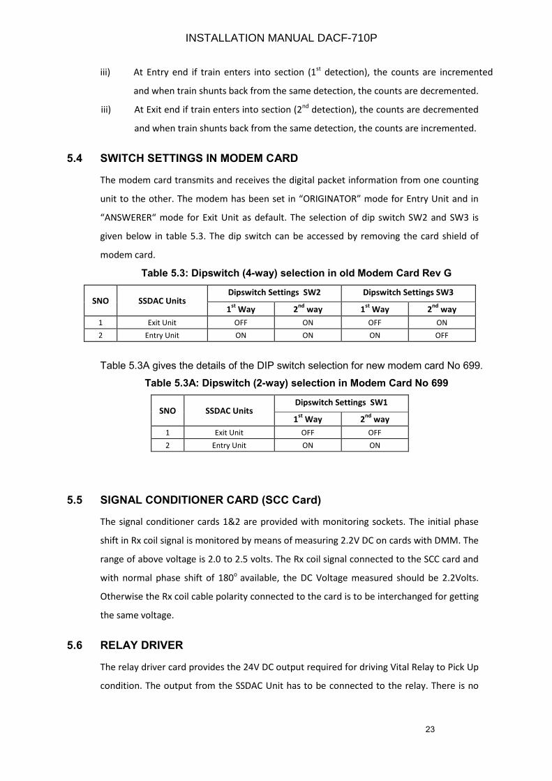
5.4 SWITCH SETTINGS IN MODEM CARD
The modem card transmits and receives the digital packet information from one counting
unit to the other. The modem has been set in “ORIGINATOR” mode for Entry Unit and in
“ANSWERER“ mode for Exit Unit as default. The selection of dip switch SW2 and SW3 is
given below in table 5.3. The dip switch can be accessed by removing the card shield of
modem card.
Table 5.3: Dipswitch (4-way) selection in old Modem Card Rev G
SNO SSDAC Units Dipswitch Settings SW2 Dipswitch Settings SW3
1st
Way 2nd
way 1st
Way 2nd
way
1 Exit Unit OFF ON OFF ON
2 Entry Unit ON ON ON OFF
Table 5.3A gives the details of the DIP switch selection for new modem card No 699.
Table 5.3A: Dipswitch (2-way) selection in Modem Card No 699
SNO SSDAC Units Dipswitch Settings SW1
1st
Way 2nd
way
1 Exit Unit OFF OFF
2 Entry Unit ON ON
5.5 SIGNAL CONDITIONER CARD (SCC Card)
The signal conditioner cards 1&2 are provided with monitoring sockets. The initial phase
shift in Rx coil signal is monitored by means of measuring 2.2V DC on cards with DMM. The
range of above voltage is 2.0 to 2.5 volts. The Rx coil signal connected to the SCC card and
with normal phase shift of 180o
available, the DC Voltage measured should be 2.2Volts.
Otherwise the Rx coil cable polarity connected to the card is to be interchanged for getting
the same voltage.
5.6 RELAY DRIVER
The relay driver card provides the 24V DC output required for driving Vital Relay to Pick Up
condition. The output from the SSDAC Unit has to be connected to the relay. There is no
INSTALLATION MANUAL DACF-710P

24
adjustment required in this card. The vital Relay is also checked (read back) in the
system as per the driving output.
5.7 DC-DC CONVERTER
The DC-DC converter card provides all DC supply voltages required for powering ON the
circuits of SSDAC. It takes 24V DC input from battery. The input range of DC-DC converter is
19.2V to 28.8V for normal working and provides specified constant output voltages in the
system.
INSTALLATION MANUAL DACF-710P
25
CHAPTER 6
6.0 SYSTEM INTER CONNECTION DETAILS
6.1 INTRODUCTION
This chapter provides the details for interconnection to be made between SSDAC counting
unit, TX / Rx axle detector, modem, Power Supply and other details. This includes the
details of MS Coupler connectors provided on SSDAC counting unit for external
connections.
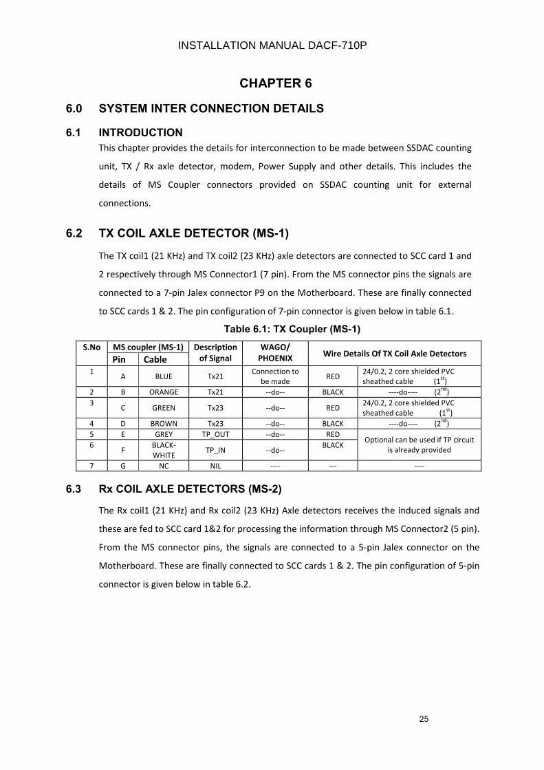
6.2 TX COIL AXLE DETECTOR (MS-1)
The TX coil1 (21 KHz) and TX coil2 (23 KHz) axle detectors are connected to SCC card 1 and
2 respectively through MS Connector1 (7 pin). From the MS connector pins the signals are
connected to a 7-pin Jalex connector P9 on the Motherboard. These are finally connected
to SCC cards 1 & 2. The pin configuration of 7-pin connector is given below in table 6.1.
Table 6.1: TX Coupler (MS-1)
S.No MS coupler (MS-1) Description
of Signal
WAGO/
PHOENIX Wire Details Of TX Coil Axle Detectors
Pin Cable 1
A BLUE Tx21 Connection to
be made RED
24/0.2, 2 core shielded PVC
sheathed cable (1st
)
2 B ORANGE Tx21 --do-- BLACK ----do---- (2nd
)
3 C GREEN Tx23 --do-- RED
24/0.2, 2 core shielded PVC
sheathed cable (1st
)
4 D BROWN Tx23 --do-- BLACK ----do---- (2nd
)
5 E GREY TP_OUT --do-- RED Optional can be used if TP circuit
is already provided 6
F BLACK-
WHITE TP_IN --do--
BLACK
7 G NC NIL ---- --- ----
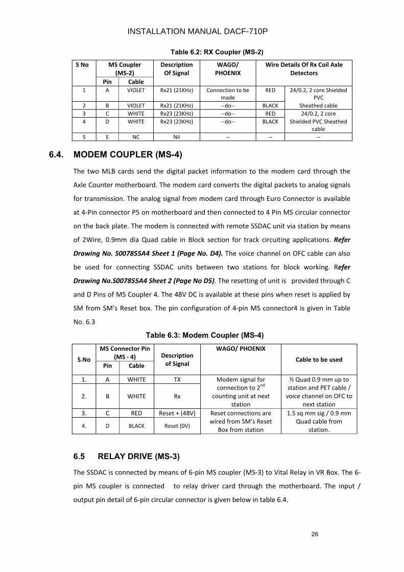
6.3 Rx COIL AXLE DETECTORS (MS-2)
The Rx coil1 (21 KHz) and Rx coil2 (23 KHz) Axle detectors receives the induced signals and
these are fed to SCC card 1&2 for processing the information through MS Connector2 (5 pin).
From the MS connector pins, the signals are connected to a 5-pin Jalex connector on the
Motherboard. These are finally connected to SCC cards 1 & 2. The pin configuration of 5-pin
connector is given below in table 6.2.
INSTALLATION MANUAL DACF-710P
26
Table 6.2: RX Coupler (MS-2)
S No MS Coupler
(MS-2)
Description
Of Signal
WAGO/
PHOENIX
Wire Details Of Rx Coil Axle
Detectors
Pin Cable
1 A VIOLET Rx21 (21KHz) Connection to be
made
RED 24/0.2, 2 core Shielded
PVC
2 B VIOLET Rx21 (21KHz) --do-- BLACK Sheathed cable
3 C WHITE Rx23 (23KHz) --do-- RED 24/0.2, 2 core
4 D WHITE Rx23 (23KHz) --do-- BLACK Shielded PVC Sheathed
cable
5 E NC Nil -- -- --
6.4. MODEM COUPLER (MS-4)
The two MLB cards send the digital packet information to the modem card through the
Axle Counter motherboard. The modem card converts the digital packets to analog signals
for transmission. The analog signal from modem card through Euro Connector is available
at 4-Pin connector P5 on motherboard and then connected to 4 Pin MS circular connector
on the back plate. The modem is connected with remote SSDAC unit via station by means
of 2Wire, 0.9mm dia Quad cable in Block section for track circuiting applications. Refer
Drawing No. S007855A4 Sheet 1 (Page No. D4). The voice channel on OFC cable can also
be used for connecting SSDAC units between two stations for block working. Refer
Drawing No.S007855A4 Sheet 2 (Page No D5). The resetting of unit is provided through C
and D Pins of MS Coupler 4. The 48V DC is available at these pins when reset is applied by
SM from SM’s Reset box. The pin configuration of 4-pin MS connector4 is given in Table
No. 6.3
Table 6.3: Modem Coupler (MS-4)
S.No
MS Connector Pin
(MS - 4) Description
of Signal
WAGO/ PHOENIX
Cable to be used Pin Cable
1. A WHITE TX Modem signal for
connection to 2nd
counting unit at next
station
½ Quad 0.9 mm up to
station and PET cable /
voice channel on OFC to
next station
2. B WHITE Rx
3. C RED Reset + (48V) Reset connections are
wired from SM’s Reset
Box from station
1.5 sq mm sig / 0.9 mm
Quad cable from
station. 4. D BLACK Reset (0V)
6.5 RELAY DRIVE (MS-3)
The SSDAC is connected by means of 6-pin MS coupler (MS-3) to Vital Relay in VR Box. The 6-
pin MS coupler is connected to relay driver card through the motherboard. The input /
output pin detail of 6-pin circular connector is given below in table 6.4.
INSTALLATION MANUAL DACF-710P
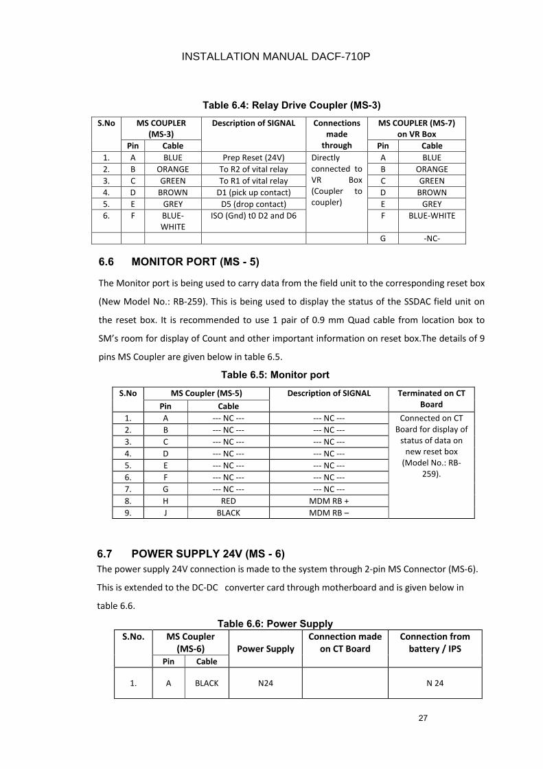
27
Table 6.4: Relay Drive Coupler (MS-3)
S.No MS COUPLER
(MS-3)
Description of SIGNAL Connections
made
through
MS COUPLER (MS-7)
on VR Box
Pin Cable Pin Cable
1. A BLUE Prep Reset (24V) Directly
connected to
VR Box
(Coupler to
coupler)
A BLUE
2. B ORANGE To R2 of vital relay B ORANGE
3. C GREEN To R1 of vital relay C GREEN
4. D BROWN D1 (pick up contact) D BROWN
5. E GREY D5 (drop contact) E GREY
6. F BLUE-
WHITE
ISO (Gnd) t0 D2 and D6 F BLUE-WHITE
G -NC-
6.6 MONITOR PORT (MS - 5)
The Monitor port is being used to carry data from the field unit to the corresponding reset box
(New Model No.: RB-259). This is being used to display the status of the SSDAC field unit on
the reset box. It is recommended to use 1 pair of 0.9 mm Quad cable from location box to
SM’s room for display of Count and other important information on reset box.The details of 9
pins MS Coupler are given below in table 6.5.
Table 6.5: Monitor port
6.7 POWER SUPPLY 24V (MS - 6)
The power supply 24V connection is made to the system through 2-pin MS Connector (MS-6).
This is extended to the DC-DC converter card through motherboard and is given below in
table 6.6.
Table 6.6: Power Supply
S.No. MS Coupler
(MS-6) Power Supply
Connection made
on CT Board
Connection from
battery / IPS
Pin Cable
1. A BLACK N24 N 24
S.No MS Coupler (MS-5) Description of SIGNAL Terminated on CT
Board Pin Cable
1. A --- NC --- --- NC --- Connected on CT
Board for display of
status of data on
new reset box
(Model No.: RB-
259).
2. B --- NC --- --- NC ---
3. C --- NC --- --- NC ---
4. D --- NC --- --- NC ---
5. E --- NC --- --- NC ---
6. F --- NC --- --- NC ---
7. G --- NC --- --- NC ---
8. H RED MDM RB +
9. J BLACK MDM RB –
INSTALLATION MANUAL DACF-710P
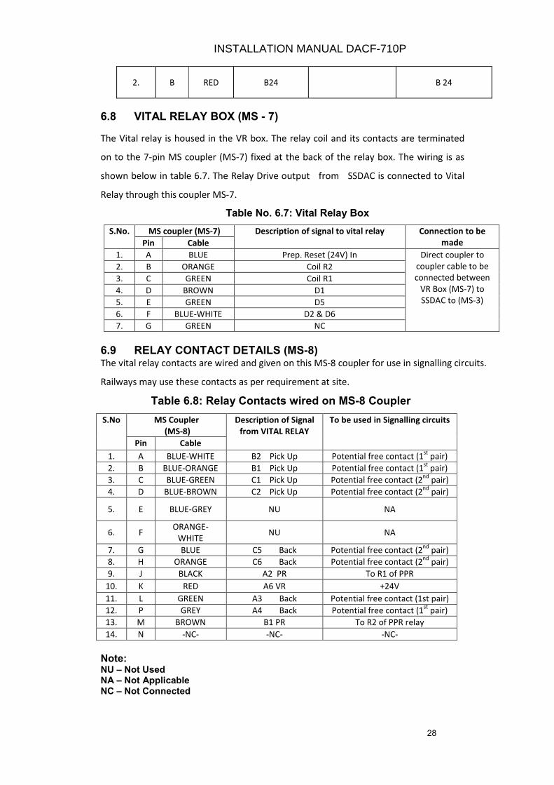
28
2. B RED B24 B 24
6.8 VITAL RELAY BOX (MS - 7)
The Vital relay is housed in the VR box. The relay coil and its contacts are terminated
on to the 7-pin MS coupler (MS-7) fixed at the back of the relay box. The wiring is as
shown below in table 6.7. The Relay Drive output from SSDAC is connected to Vital
Relay through this coupler MS-7.
Table No. 6.7: Vital Relay Box
S.No. MS coupler (MS-7) Description of signal to vital relay Connection to be
made Pin Cable
1. A BLUE Prep. Reset (24V) In Direct coupler to
coupler cable to be
connected between
VR Box (MS-7) to
SSDAC to (MS-3)
2. B ORANGE Coil R2
3. C GREEN Coil R1
4. D BROWN D1
5. E GREEN D5
6. F BLUE-WHITE D2 & D6
7. G GREEN NC
6.9 RELAY CONTACT DETAILS (MS-8) The vital relay contacts are wired and given on this MS-8 coupler for use in signalling circuits.
Railways may use these contacts as per requirement at site.
Table 6.8: Relay Contacts wired on MS-8 Coupler
S.No MS Coupler
(MS-8)
Description of Signal
from VITAL RELAY
To be used in Signalling circuits
Pin Cable
1. A BLUE-WHITE B2 Pick Up Potential free contact (1st
pair)
2. B BLUE-ORANGE B1 Pick Up Potential free contact (1st
pair)
3. C BLUE-GREEN C1 Pick Up Potential free contact (2nd
pair)
4. D BLUE-BROWN C2 Pick Up Potential free contact (2nd
pair)
5. E BLUE-GREY NU NA
6. F ORANGE-
WHITE NU NA
7. G BLUE C5 Back Potential free contact (2nd
pair)
8. H ORANGE C6 Back Potential free contact (2nd
pair)
9. J BLACK A2 PR To R1 of PPR
10. K RED A6 VR +24V
11. L GREEN A3 Back Potential free contact (1st pair)
12. P GREY A4 Back Potential free contact (1st
pair)
13. M BROWN B1 PR To R2 of PPR relay
14. N -NC- -NC- -NC-
Note: NU – Not Used NA – Not Applicable NC – Not Connected
INSTALLATION MANUAL DACF-710P

29
CHAPTER 7
7.0 MEASUREMENT OF SIGNAL LEVELS
The various signal input & output levels and its limits are given in the following tables. This
should be recorded and adjusted to correct levels wherever necessary.
7.1 24V DC SUPPLY (BATTERY)
Measure the DC 24V input to the system with charger on, charger off condition with all the
units connected (i.e. on load) or using dummy load.
S.No. Input Range near SSDAC unit
(In DC Volts)
Actual measured value
With Charger ON Charger OFF
1. 19.2 V to 28.8 V
Note : Keep Charger OFF for 15 mins before taking measurements
7.2 OSCILLATOR OUTPUT (TX Coils) Measure the oscillator output, frequency of TX coil Axle detectors.
S.No Parameter Limit TX Coil 1
(21KHz)
TX Coil 2
(23KHz)
1. Oscillator output 30V to 40Vrms
2. Oscillator Freq.
I) 20.80 to 21.20 KHz
II) 22.80 to 23.20 KHz
7.3 RECEIVER COIL OUTPUT
Measure the Rx coil signal output
S.No. Parameter Limit
mV rms
Measured
Value
1. Rx Coil 1 (21KHz) 275 to 600
2. Rx Coil 2 (23KHz) 275 to 600
INSTALLATION MANUAL DACF-710P
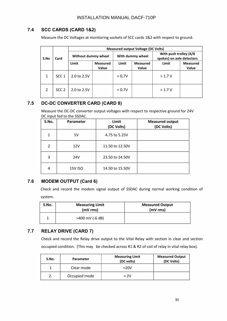
30
7.4 SCC CARDS (CARD 1&2)
Measure the DC Voltages at monitoring sockets of SCC cards 1&2 with respect to ground.
7.5 DC-DC CONVERTER CARD (CARD 8)
Measure the DC-DC converter output voltages with respect to respective ground for 24V
DC input fed to the SSDAC.
S.No. Parameter Limit
(DC Volts)
Measured output
(DC Volts)
1 5V 4.75 to 5.25V
2 12V 11.50 to 12.50V
3 24V 23.50 to 24.50V
4 15V ISO 14.50 to 15.50V
7.6 MODEM OUTPUT (Card 6)
Check and record the modem signal output of SSDAC during normal working condition of
system.
S.No. Measuring Limit
(mV rms)
Measured Output
(mV rms)
1 >400 mV (-6 dB)
7.7 RELAY DRIVE (CARD 7)
Check and record the Relay drive output to the Vital Relay with section in clear and section
occupied condition. (This may be checked across R1 & R2 of coil of relay in vital relay box).
S.No. Parameter Measuring Limit
(DC volts)
Measured Output
(DC Volts)
1 Clear mode >20V
2. Occupied mode < 2V
S.No Card
Measured output Voltage (DC Volts)
Without dummy wheel With dummy wheel With push trolley (4/8
spokes) on axle detectors
Limit Measured
Value
Limit Measured
Value
Limit Measured
Value
1 SCC 1 2.0 to 2.5V < 0.7V > 1.7 V
2 SCC 2 2.0 to 2.5V < 0.7V > 1.7 V
INSTALLATION MANUAL DACF-710P
31
CHAPTER 8
8.0 COMMUNICATION PROTOCOL
8.1 INTRODUCTION
The SSDAC counting units communicate with each other to share information regarding status
of wheel counts and health information. The communication protocol comprises of following
packets.
i Power On & Reset Packets ‘J’ and ‘R’
Ii Count Change Packet ‘C’
Iii Count Update Packet ‘U’
These packets are described in detail below.
8.2 POWER ON AND RESET PACKETS ‘J’ AND ‘R’
The Reset Packets are of two types - J Packet and R Packet. After Power ON to the system, the
SSDAC units are energized and are holding in stuck condition. The SSDAC Units are waiting for
Reset command from SM’s Reset box. After applying the Reset from SM’s reset box, the
resetting takes place in the units and SSDAC performs the self-test. After successfully
completing the self-test the local unit generates the J Packet and sends to the remote unit and
vice versa. This reset packet includes the system status. The R Packet is received from the
remote unit against the transmitted J Packet from local unit. Then both units go into hand
shaking mode and come to preparatory reset condition. The SSDAC keeps sending the J Packet
at regular intervals till R Packet is received from the other SSDAC.
8.3 COUNT CHANGE PACKET ‘C’
This packet is sent by the SSDAC if the count status changes from Matching to Mismatching.
This normally happens after the wheel count from 1st
wheel of train is detected in clear state.
This packet is basically used to warn the remote SSDAC that a train is entering the section
from this end and that the remote SSDAC to change the Status to OCCUPIED.
8.4 COUNT UPDATE PACKET ‘U’
The Count Update Packet is sent by an SSDAC to Remote SSDAC every 800 milliseconds. This
packet carries the Status of wheel count and health to the remote SSDAC and Vice Versa.
INSTALLATION MANUAL DACF-710P
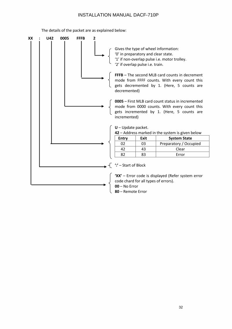
32
The details of the packet are as explained below:
XX : U42 0005 FFFB 2
Gives the type of wheel information:
‘0’ in preparatory and clear state.
‘1’ if non-overlap pulse i.e. motor trolley.
‘2’ if overlap pulse i.e. train.
FFFB – The second MLB card counts in decrement
mode from FFFF counts. With every count this
gets decremented by 1. (Here, 5 counts are
decremented)
0005 – First MLB card count status in incremented
mode from 0000 counts. With every count this
gets incremented by 1. (Here, 5 counts are
incremented)
U – Update packet.
42 – Address marked in the system is given below
Entry Exit System State
02 03 Preparatory / Occupied
42 43 Clear
82 83 Error
‘:’ – Start of Block
‘XX’ – Error code is displayed (Refer system error
code chard for all types of errors).
00 – No Error
80 – Remote Error
INSTALLATION MANUAL DACF-710P
33
CHAPTER 9
9.0 SYSTEM SOFTWARE
9.1 INTRODUCTION
As described in earlier chapters, the system is designed with two micro controller logic block
card (MLB) in the SSDAC. Both the MLB’s are performing exactly the same functions. Both the
MLB’s are receiving the pulse and supervisory signals from the Signal Conditioning cards. The
MLB’s are continuously monitoring and evaluating the pulse and supervisory signals coming
from the Signal Conditioning cards. The MLB’s validate the pulse signals from wheels and the
direction of train movement. Accordingly, the number of wheels is counted from passing
wheels over the detection points. Each MLB, after detecting pulses, keeps sending a copy of it
to the other MLB.
The MLB’s are programmed to perform the following functions.
i. Monitor and Receive Pulse signals
ii. Output Pulse signals to other MLB
iii. Detect the passing wheels and its direction.
iv. Count the wheels passing at the Axle detectors
v. Supervise the Axle detectors
vi. Code message packets for transmission to remote SSDAC
vii. Decode message packets received from the remote SSDAC
viii. Determine the number of axles in the section
ix. Control and supervise the status of Vital Relay
Each MLB keeps track of three different counts -
i. Primary Count Its own wheel count
ii. Secondary Count wheel count of 2nd
micro controller and
iii. Remote Count Count values of remote SSDAC unit.
Each MLB continuously monitors the Pulse input signals and filters them through software
filter. It then regenerates equivalent pulse output levels for transmission to the other MLB.
Therefore, the other MLB gets filtered pulse equivalent signals of the original pulse input
signals after a short delay of up to a maximum of 50 microseconds. Hence, each of the two
MLB’s checks the original pulse input signals and filtered pulse signals received from other
MLB and keeps two sets of wheel counts; Primary count for the original pulse inputs and
Secondary counts for the filtered pulse inputs received from the other MLB.
INSTALLATION MANUAL DACF-710P
34
In SSDAC unit, the first MLB card sends the primary count as well as the secondary count
to the remote SSDAC on regular basis of every 800 milliseconds using Update Count
Packet. When the SSDAC detects the first train wheel entering the Track Section, it sends
a Count Change Packet to the remote SSDAC.
9.2 COUNTING OF WHEELS AND COMPUTATION OF DIRECTION
There are two pulse inputs, PULSE1 (21 KHz) and PULSE2 (23 KHz), from the Signal
Conditioning cards. PULSE1 (21 KHz) is generated from the phase-modulated signal
received from Rx1 coil. Similarly, PULSE2 (23 KHz) is generated from the phase-
modulated signal received from Rx2 coil. PULSE1 (21 KHz) and PULSE2 (23 KHz) signals
are normally ‘high’ and go ‘low’ when a wheel passes over the respective Rx coil.
Sequence of PULSE1 (21 KHz)/PULSE2 (23 KHz) signals gives the direction of movement
of train. If PULSE1 (21 KHz) goes low before PULSE2 (23 KHz) then wheel is moving from
Rx1 coil to Rx2 coil. If PULSE2 (23 KHz) goes low before PULSE1 (21 KHz) then wheel is
moving from Rx2 coil to Rx1 coil.
Drawing no L008077A3 (Page No D7) & Drawing no I007765A4 (Page No D8) give the
typical types of PULSE1 (21 KHz) / PULSE2 (23 KHz) signals. (i) Shows a wheel crossing the
detection point and moving from Rx1 coil towards Rx2 coil. (ii) Shows a wheel crossing
the detection point and moving from Rx2 coil towards Rx1 coil.
This scheme of wheel counting is implemented in software using a State machine
approach. Change in pulse inputs result in change of state. Wheel direction from Rx1 coil
to Rx2 coil is taken as positive and wheel count is incremented. Similarly, wheel direction
from Rx2 coil to Rx1 coil is taken as negative and wheel count is decremented. It may be
noted that wheel count is incremented or decremented only when the wheel completely
crosses the detection point.
9.3 FUNCTIONAL STATES OF SSDAC
The SSDAC functional states are implemented as a set of four states. This is shown in
Drawing no L007758A3 (Page No. D26). At any point of time, the SSDAC is internally in
any one of the following four states.
i. Preparatory Reset Reset applied
ii. Clear Section clear
iii. Occupied Section occupied
iv. Disturbed Error in the system
These states are described below.
INSTALLATION MANUAL DACF-710P
35
9.3.1 PREPARATORY RESET STATE (RESET APPLIED)
This is the state of the system when the Reset is applied in the units. The Reset is to be
applied in SSDAC after ensuring that there is no train in the block section. After which
the SSDAC units performs Self Test and the units are normal the system goes to
preparatory state. The SSDAC comes to clear state after movement of a pilot train in the
section.
9.3.2 CLEAR STATE (SECTION CLEAR)
The SSDAC unit enters this state when the net counts value of the section matches
(wheel count are same in both the Counting Units of SSDAC in the section). The local
count value of both the MLB’s is identical and is same as that of the counts received from
the remote SSDAC. The health status of both the SSDAC units is also OK.
9.3.3 OCCUPIED STATE (SECTION OCCUPIED)
The SSDAC unit enters this state when the count value of the section is different between
the two units of SSDAC or when a wheel is occupying over a single Axle detector or due
to any error in the system it is shown as occupied.In SSDAC, VR drops in case any single
channel is influenced by train wheel and continues to be dropped till the channel is
restored. Such influence is allowed only twice and system goes to Error State.
9.3.4 DISTURBED STATE (ERROR IN THE SYSTEM)
The SSDAC unit enters the error state when: -
i. The counted wheels in the section becomes negative
ii. The count & health data of two MLB’s in the SSDAC unit is different
iii. Any card is removed from the unit
iv. An internal error is detected during self-test
v. The Vital Relay pick up and drop detected is improper
vi. The vital Relay is not plugged in vital relay box.
vii. Address setting of the unit is changed and disturbed during operation
viii. The communication link between two units of SSDAC is disconnected (open).
ix. The Axle detectors are giving low signals
x. The Axle detectors are showing open condition
xi. The watchdog timer gives time out
xii. Reset has been applied in one of the SSDAC units.
All the above errors are displayed in MLB cards by means of error code.
INSTALLATION MANUAL DACF-710P
36
CHAPTER 10
10.0 LED INDICATIONS
10.1 INTRODUCTION
The LED indications are provided on the facial plate i.e. on front side of different
modules of SSDAC to indicate OK or Error condition. These are as follows: -
1. SCC CARDS
i. OSC OK (Green LED)
ii. LD OK (Green LED)
iii. PULSE OK (Green LED)
iv. TP CON (Green LED)
The above LED’s (i) to (iii) will be glowing for OK condition. The LED (iv) TP circuit
is not operational and LED will be in OFF condition.
2. MLB CARDS
i. 8 LED BLOCK (All Red LED’s) - Normally OFF. Glows when error appears.
ii. Clear (Green LED) - Glows for clear condition
iii. Occupied (Red LED) - Glows for occupied condition
3. MODEM CARDi. TX (Green LED) - Transmitting the signal when LED is flashing.
ii. Rx (Green LED) - Receiving the signal when LED is flashing.
iii. MODE (Green LED) - Normally remains OFF. When system is made OFF and ON,
LED glows and again goes low when system enters self test after successful
reset.
iv. CD (Green LED) - Carrier is detected when LED is glowing.
4. RELAY DRIVER
i. MLB1 CLEAR (Green LED)
ii. MLB1 CLOCK (Green LED) - LED flashes when section is clear
iii. MLB2 CLEAR (Green LED)
iv. MLB2 CLOCK (Green LED)- LED flashes when section is clear
v. RELAY DRIVE (Green LED) - Remains OFF for section occupied and glows when
section is Clear.
All the above LED’s are lit for section clear condition
5. DC-DC CONVERTERi. + 5V (Red LED)
INSTALLATION MANUAL DACF-710P
37
ii. +12V (Red LED)
iii. +24V (Red LED)
iv. +15V ISO (Red LED)
All the above LED’s are lit for power supply OK condition.
6. EVENT LOGGER
i. Run (Green LED)
ii. LOG (Green LED)
iii. Dnld (Green LED)
10.2 SCC CARDS (Card 1 & 2)
i. OSC OK – This LED indication will indicate the normal working of the TX coil and the
oscillator. In case TX coil is short, the OSC OK indication will not glow. During train
movement, this LED continues to glow.
ii. LD OK – This LED indication will indicate the health of the Rx coil. The LEVEL
DETECTOR (LD) indication will indicate that the signal from Rx coils are normal and
above a certain level. The LD OK LED indication will be OFF in case of
a. Fault in Rx coil
b. Rx coil cable is disconnected
iii. PULSE OK – This LED indicates the normal signal from Rx coil and Pulse level in Card is
OK. This indication will not glow in case of
a. Fault in Rx coil.
b. Rx cables are connected in reverse polarity.
c. Rx coil cable is disconnected.
During train movement, this LED changes between OFF and ON. It is visible during slow
movement of train
iv. TP Con - This LED remains OFF permanently as trolley suppression circuit is not
required in phase reversal type system
10.3 MLB CARDS (CARD 3 & 4)
10.3.1 The errors occurring in the system during the operation of the SSDAC are encoded and are
indicated by means of the 8-LED block present on the front panel of the MLB cards. A
glowing LED implies a ‘1’ while OFF LED indicates a ‘0’. All the LED‘s are numbered as given
below. DS 1 to DS4 are designated for Least Significant Bits (LSB) and DS5 to DS8 are
designated for High Significant Bits (HSB). The Error is given in Hexa decimal code
INSTALLATION MANUAL DACF-710P
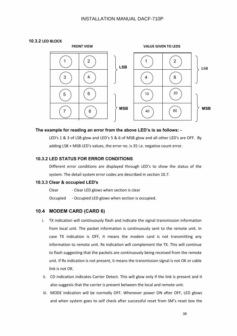
38
10.3.2 LED BLOCK
FRONT VIEW VALUE GIVEN TO LEDS
LSB
HSB HSB
MSB MSB
The example for reading an error from the above LED’s is as follows: -
LED's 1 & 3 of LSB glow and LED’s 5 & 6 of MSB glow and all other LED's are OFF. By
adding LSB + MSB LED’s values, the error no. is 35 i.e. negative count error.
10.3.2 LED STATUS FOR ERROR CONDITIONS
Different error conditions are displayed through LED’s to show the status of the
system. The detail system error codes are described in section 10.7.
10.3.3 Clear & occupied LED's
Clear - Clear LED glows when section is clear
Occupied - Occupied LED glows when section is occupied.
10.4 MODEM CARD (CARD 6)
i. TX indication will continuously flash and indicate the signal transmission information
from local unit. The packet information is continuously sent to the remote unit. In
case TX indication is OFF, it means the modem card is not transmitting any
information to remote unit. Rx indication will complement the TX. This will continue
to flash suggesting that the packets are continuously being received from the remote
unit. If Rx indication is not present, it means the transmission signal is not OK or cable
link is not OK.
ii. CD indication indicates Carrier Detect. This will glow only if the link is present and it
also suggests that the carrier is present between the local and remote unit.
iii. MODE indication will be normally OFF. Whenever power ON after OFF, LED glows
and when system goes to self check after successful reset from SM’s reset box the
11 2
4 3
5 6
8 7
1 2
8 4
10 20
80 40
INSTALLATION MANUAL DACF-710P
LSB
39
LED goes OFF. In error condition if reset is applied, MODE LED glows and
immediately goes OFF.
10.5 RELAY DRIVER CARD (CARD 7)
I. After counts are balanced in the section, the clear signal will be generated by MLB1 card
and MLB1 CLEAR LED indication will glow in this card. When the section is occupied MLB 1
detects occupied and this LED indication becomes OFF.
II. MLB1 CLOCK LED indicates the presence of Clock from MLB1 card after the counts are
balanced. The flashing of this LED indicates the presence of Clock to relay driver card. This
indication is OFF / ON depending on the interruption of clock from MLB1 when the section is
occupied by a train.
III. After counts are balanced in the section, the clear signal will be generated by MLB1 card
and MLB2 CLEAR LED indication in this card will glow. When the section is occupied MLB2
detects occupied and this LED indication becomes OFF.
IV. MLB2 CLOCK LED indicates the presence of Clock from MLB2 card after the counts are
balanced in the section. The flashing of this LED indicates the presence of Clock to relay
driver card. This indication is OFF / ON depending on the interruption of clock from MLB2
when a train occupies the section.
V. RELAY DRIVE LED indicates the presence of Relay Drive output (24V DC) to Q type relay
from Relay Driver card. The LED glows when the relay drive output is present. When Relay
Drive output is not present this LED is OFF.
10.6 DC-DC CONVERTER (CARD 8)
I. + 5V LED OK indication suggests the presence of +5V in the DC-DC converter card. This
indication is OFF during the failure of 5V in DC-DC converter card.
II. +12V LED OK indication suggests the presence of +12V in the DC-DC converter card. This
indication is OFF during the failure of 12V in DC-DC converter card.
III. +24V LED OK indication suggests the presence of +24V in the DC-DC converter card. This
indication is OFF during the failure of 24V in DC-DC converter card.
IV. +15V ISO LED OK indication suggests the presence of +15V ISO in the DC-DC converter card.
This indication is OFF during the failure of 15V ISO in DC-DC converter card.
10.7 EVENT LOGGER CARD (Card 5)
i. Run This LED blinks continuously indicating the normal working of the event logger card.
INSTALLATION MANUAL DACF-710P

40
ii. Log This LED blinks whenever data is being logged into the flash memory (approx, after
every 2 minutes)
iii. Dnld This LED is ON when data is being downloaded from the flash memory of the card and
becomes OFF when download is complete.
10.8 SYSTEM ERROR CODES
The two MLB cards continuously check and monitor the health of the system. During Normal
working condition of the system, there won’t be any error and all the LED’s are OFF. When the
system detects error, it will be displayed on these cards by means of flashing / glowing one or
more LED’s for the particular error. The list of error codes and their respective glow of LED’s are
given below. The corrective action may be taken accordingly.
S. NO ERROR ERROR
NUMBER (Hex
decimal)
ERROR DUE TO
1. SYSTEM NORMAL (NO ERROR) 00 NORMAL
2. ROM_TEST_DURING POST 11 ROM TEST DURING POST
3. RAM_TEST_DURING POST 12 RAM TEST DURING POST
4. SERIAL_TEST_DURING POST 13 SERIAL PORT TEST DURING POST
5. CARD_TEST_DURING POST 14 CARD PRESENCE TEST DURING POST
6. RELAY_TEST_DURIN POST 15 RELAY TEST FAIL DURING POST
7. ROM_TEST_DURING SYS WORKING 21 ROM TEST FAIL DURING SYSTEM WORKING
8. RAM_TEST_DURING SYS WORKING 22 RAM TEST FAIL DURING SYSTEM WORKING
9. CARD_TEST_DURING SYS WORKING 24 CARD PRESENCE FAIL DURING SYSTEM WORKING
10. LINK ERROR 30 LOSS OF CARRIER OR LINK
11. SEQUENCE ERROR 31 SEQUENCE OF INPUTS MISMATCH
12. SELF_COUNT_MISMATCH 32 SELF COUNT MISMATCH ERROR
13. INOUT_ERROR 33 MOVEMENT OF TRAIN BEFORE PREPARATORY RESET
14. OUT_B4_IN_ERROR 34 REGISTRATION OF OUTCOUNT BEFORE INCOUNT
15. NEGATIVE_COUNT_ERROR 35 NEGATIVE COUNT ERROR
16. SHUNT_ERROR 36 SHUNT ERROR
17. SUPERVISORY_ERROR 37 SUPERVISORY ERROR
18. INTERNAL_SHUNT_ERROR 38 INTERNAL SHUNT ERROR
19. COUNT UNEQUAL ERROR 39 COUNTS MISMATCH IN MLB OF SAME UNIT
20 COMMUNICATION_ERROR 40 CORRUPTION OF PACKETS
21 CRC_ERROR_CONST 41 CORRUPTION OF DATA
22. EOB_ERROR_CONST 42 CORRUPTION OF DATA
23. WHEEL_SHUNT_ERROR 43 WHEEL SHUNT ERROR
24. INDEPENDENT PULSE ERROR(FORWARD) 44 OCCURRENCE OF NON OVERLAPPING PULSE IN FORWARD
DIRECTION
25. INDEPENDENT PULSE ERROR(REVERSE) 45 OCCURRENCE OF NON OVERLAPPNG PULSE IN REVERSE
DIRECTION
26. EXIT MISMATCH ERROR 46 TRAIN / TROLLEY IN AND TROLLEY / TRAIN OUT.
27. TRAIN TROLLEY ERROR 47 FOLLOWING TROLLEY SHUNTS BACK.
28. NON OVERLAP B4 OVERLAP ERROR 48 TRAIN ENTERS AFTER MOTOR TROLLEY.
29. RELAY ERROR DURING POST (CLR) 50 RELAY ERROR DURING POST IN CLR STATE
30. RELAY ERROR DURING POST (OCC) 51 RELAY ERROR DURING POST IN OCC STATE.
31. RELAY ERROR DURING CLR STATE. 52 RELAY CONTACT NOT READ BACK IN CLR STATE
32. RELAY ERROR DURING OCC STATE 53 RELAY CONTACT NOT READ BACK IN OCC STATE
INSTALLATION MANUAL DACF-710P
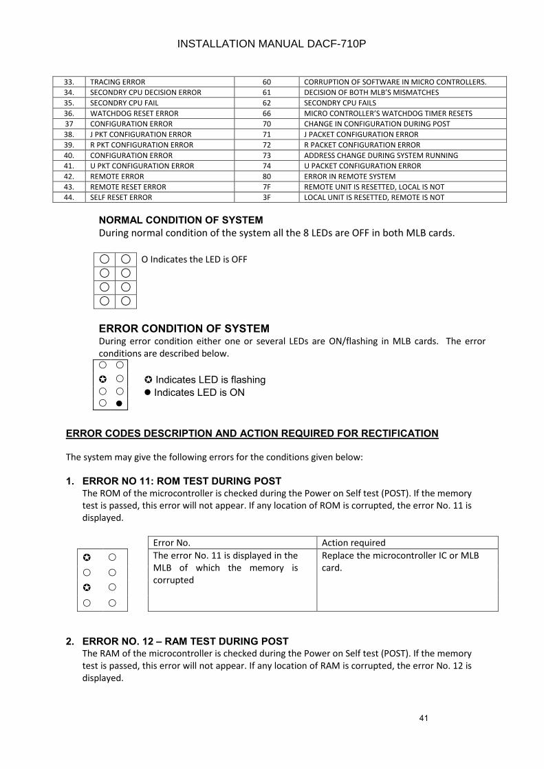
41
33. TRACING ERROR 60 CORRUPTION OF SOFTWARE IN MICRO CONTROLLERS.
34. SECONDRY CPU DECISION ERROR 61 DECISION OF BOTH MLB’S MISMATCHES
35. SECONDRY CPU FAIL 62 SECONDRY CPU FAILS
36. WATCHDOG RESET ERROR 66 MICRO CONTROLLER’S WATCHDOG TIMER RESETS
37 CONFIGURATION ERROR 70 CHANGE IN CONFIGURATION DURING POST
38. J PKT CONFIGURATION ERROR 71 J PACKET CONFIGURATION ERROR
39. R PKT CONFIGURATION ERROR 72 R PACKET CONFIGURATION ERROR
40. CONFIGURATION ERROR 73 ADDRESS CHANGE DURING SYSTEM RUNNING
41. U PKT CONFIGURATION ERROR 74 U PACKET CONFIGURATION ERROR
42. REMOTE ERROR 80 ERROR IN REMOTE SYSTEM
43. REMOTE RESET ERROR 7F REMOTE UNIT IS RESETTED, LOCAL IS NOT
44. SELF RESET ERROR 3F LOCAL UNIT IS RESETTED, REMOTE IS NOT
NORMAL CONDITION OF SYSTEM
During normal condition of the system all the 8 LEDs are OFF in both MLB cards.
O Indicates the LED is OFF
ERROR CONDITION OF SYSTEM During error condition either one or several LEDs are ON/flashing in MLB cards. The error
conditions are described below.
Indicates LED is flashing
Indicates LED is ON
ERROR CODES DESCRIPTION AND ACTION REQUIRED FOR RECTIFICATION
The system may give the following errors for the conditions given below:
1. ERROR NO 11: ROM TEST DURING POST
The ROM of the microcontroller is checked during the Power on Self test (POST). If the memory
test is passed, this error will not appear. If any location of ROM is corrupted, the error No. 11 is
displayed.
Error No. Action required
The error No. 11 is displayed in the
MLB of which the memory is
corrupted
Replace the microcontroller IC or MLB
card.
2. ERROR NO. 12 – RAM TEST DURING POSTThe RAM of the microcontroller is checked during the Power on Self test (POST). If the memory
test is passed, this error will not appear. If any location of RAM is corrupted, the error No. 12 is
displayed.
INSTALLATION MANUAL DACF-710P
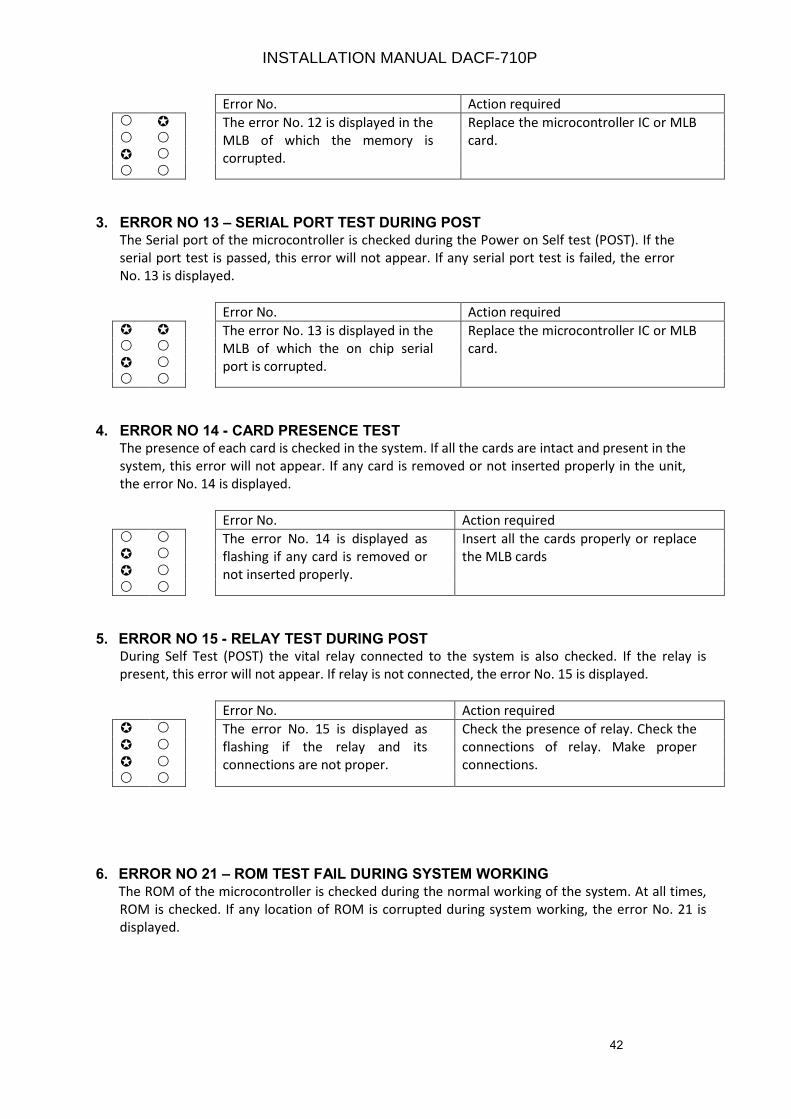
42
Error No. Action required
The error No. 12 is displayed in the
MLB of which the memory is
corrupted.
Replace the microcontroller IC or MLB
card.
3. ERROR NO 13 – SERIAL PORT TEST DURING POSTThe Serial port of the microcontroller is checked during the Power on Self test (POST). If the
serial port test is passed, this error will not appear. If any serial port test is failed, the error
No. 13 is displayed.
Error No. Action required
The error No. 13 is displayed in the
MLB of which the on chip serial
port is corrupted.
Replace the microcontroller IC or MLB
card.
4. ERROR NO 14 - CARD PRESENCE TESTThe presence of each card is checked in the system. If all the cards are intact and present in the
system, this error will not appear. If any card is removed or not inserted properly in the unit,
the error No. 14 is displayed.
Error No. Action required
The error No. 14 is displayed as
flashing if any card is removed or
not inserted properly.
Insert all the cards properly or replace
the MLB cards
5. ERROR NO 15 - RELAY TEST DURING POSTDuring Self Test (POST) the vital relay connected to the system is also checked. If the relay is
present, this error will not appear. If relay is not connected, the error No. 15 is displayed.
Error No. Action required
The error No. 15 is displayed as
flashing if the relay and its
connections are not proper.
Check the presence of relay. Check the
connections of relay. Make proper
connections.
6. ERROR NO 21 – ROM TEST FAIL DURING SYSTEM WORKING
The ROM of the microcontroller is checked during the normal working of the system. At all times,
ROM is checked. If any location of ROM is corrupted during system working, the error No. 21 is
displayed.
INSTALLATION MANUAL DACF-710P
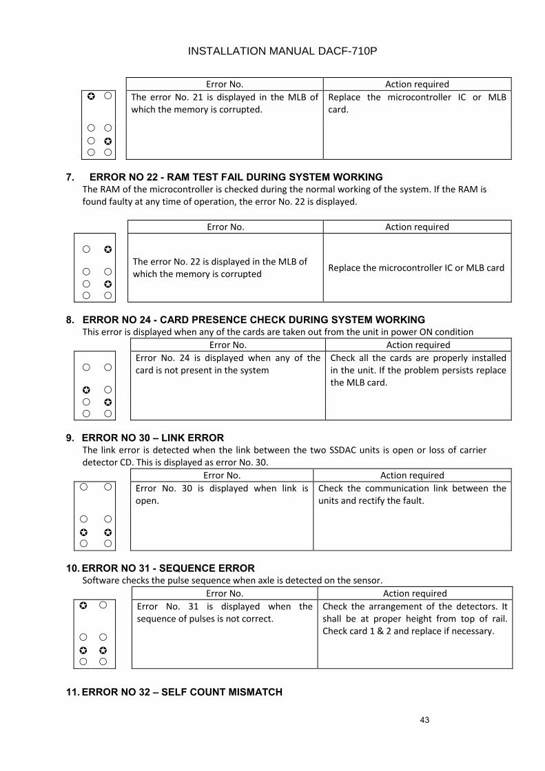
43
Error No. Action required
The error No. 21 is displayed in the MLB of
which the memory is corrupted.
Replace the microcontroller IC or MLB
card.
7. ERROR NO 22 - RAM TEST FAIL DURING SYSTEM WORKING
The RAM of the microcontroller is checked during the normal working of the system. If the RAM is
found faulty at any time of operation, the error No. 22 is displayed.
Error No. Action required
The error No. 22 is displayed in the MLB of
which the memory is corrupted Replace the microcontroller IC or MLB card
8. ERROR NO 24 - CARD PRESENCE CHECK DURING SYSTEM WORKINGThis error is displayed when any of the cards are taken out from the unit in power ON condition
Error No. Action required
Error No. 24 is displayed when any of the
card is not present in the system
Check all the cards are properly installed
in the unit. If the problem persists replace
the MLB card.
9. ERROR NO 30 – LINK ERROR
The link error is detected when the link between the two SSDAC units is open or loss of carrier
detector CD. This is displayed as error No. 30.
Error No. Action required
Error No. 30 is displayed when link is
open.
Check the communication link between the
units and rectify the fault.
10. ERROR NO 31 - SEQUENCE ERRORSoftware checks the pulse sequence when axle is detected on the sensor.
Error No. Action required
Error No. 31 is displayed when the
sequence of pulses is not correct.
Check the arrangement of the detectors. It
shall be at proper height from top of rail.
Check card 1 & 2 and replace if necessary.
11. ERROR NO 32 – SELF COUNT MISMATCH
INSTALLATION MANUAL DACF-710P
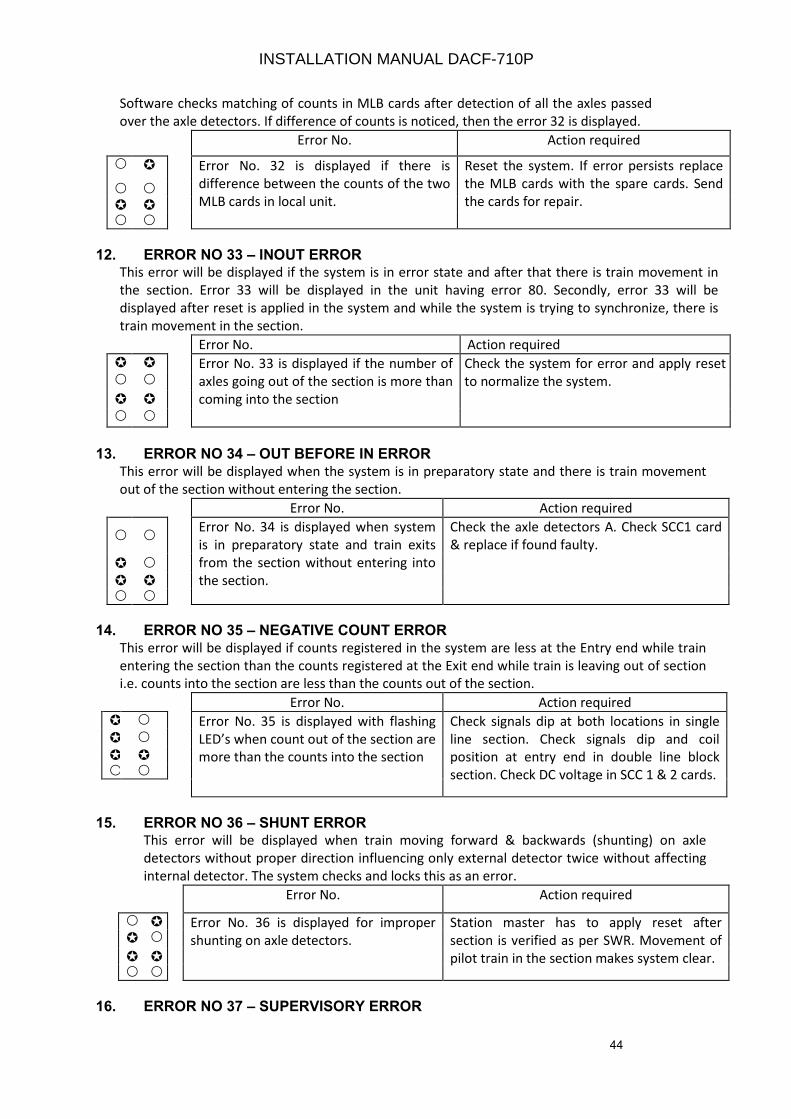
44
Software checks matching of counts in MLB cards after detection of all the axles passed
over the axle detectors. If difference of counts is noticed, then the error 32 is displayed.
Error No. Action required
Error No. 32 is displayed if there is
difference between the counts of the two
MLB cards in local unit.
Reset the system. If error persists replace
the MLB cards with the spare cards. Send
the cards for repair.
12. ERROR NO 33 – INOUT ERRORThis error will be displayed if the system is in error state and after that there is train movement in
the section. Error 33 will be displayed in the unit having error 80. Secondly, error 33 will be
displayed after reset is applied in the system and while the system is trying to synchronize, there is
train movement in the section.
Error No. Action required
Error No. 33 is displayed if the number of
axles going out of the section is more than
coming into the section
Check the system for error and apply reset
to normalize the system.
13. ERROR NO 34 – OUT BEFORE IN ERROR
This error will be displayed when the system is in preparatory state and there is train movement
out of the section without entering the section.
Error No. Action required
Error No. 34 is displayed when system
is in preparatory state and train exits
from the section without entering into
the section.
Check the axle detectors A. Check SCC1 card
& replace if found faulty.
14. ERROR NO 35 – NEGATIVE COUNT ERROR
This error will be displayed if counts registered in the system are less at the Entry end while train
entering the section than the counts registered at the Exit end while train is leaving out of section
i.e. counts into the section are less than the counts out of the section.
Error No. Action required
Error No. 35 is displayed with flashing
LED’s when count out of the section are
more than the counts into the section
Check signals dip at both locations in single
line section. Check signals dip and coil
position at entry end in double line block
section. Check DC voltage in SCC 1 & 2 cards.
15. ERROR NO 36 – SHUNT ERRORThis error will be displayed when train moving forward & backwards (shunting) on axle
detectors without proper direction influencing only external detector twice without affecting
internal detector. The system checks and locks this as an error.
Error No. Action required
Error No. 36 is displayed for improper
shunting on axle detectors.
Station master has to apply reset after
section is verified as per SWR. Movement of
pilot train in the section makes system clear.
16. ERROR NO 37 – SUPERVISORY ERROR
INSTALLATION MANUAL DACF-710P
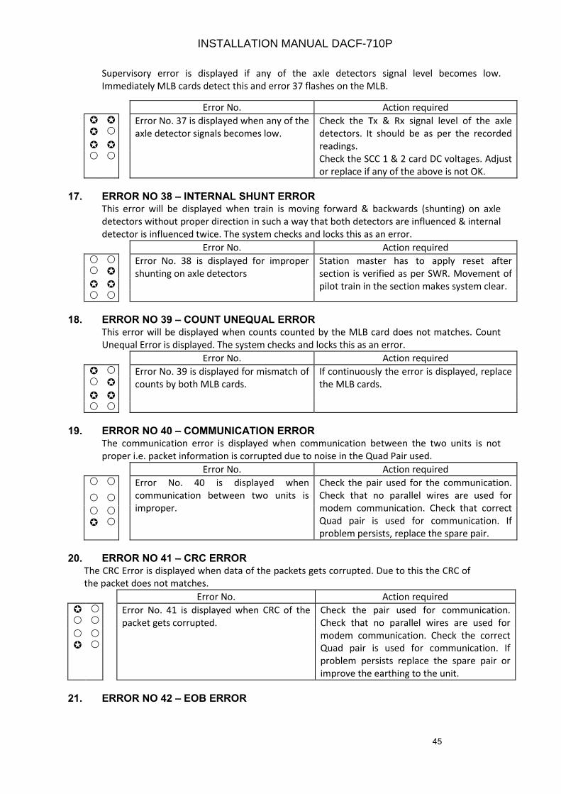
45
Supervisory error is displayed if any of the axle detectors signal level becomes low.
Immediately MLB cards detect this and error 37 flashes on the MLB.
Error No. Action required
Error No. 37 is displayed when any of the
axle detector signals becomes low.
Check the Tx & Rx signal level of the axle
detectors. It should be as per the recorded
readings.
Check the SCC 1 & 2 card DC voltages. Adjust
or replace if any of the above is not OK.
17. ERROR NO 38 – INTERNAL SHUNT ERRORThis error will be displayed when train is moving forward & backwards (shunting) on axle
detectors without proper direction in such a way that both detectors are influenced & internal
detector is influenced twice. The system checks and locks this as an error.
Error No. Action required
Error No. 38 is displayed for improper
shunting on axle detectors
Station master has to apply reset after
section is verified as per SWR. Movement of
pilot train in the section makes system clear.
18. ERROR NO 39 – COUNT UNEQUAL ERROR
This error will be displayed when counts counted by the MLB card does not matches. Count
Unequal Error is displayed. The system checks and locks this as an error.
Error No. Action required
Error No. 39 is displayed for mismatch of
counts by both MLB cards.
If continuously the error is displayed, replace
the MLB cards.
19. ERROR NO 40 – COMMUNICATION ERROR
The communication error is displayed when communication between the two units is not
proper i.e. packet information is corrupted due to noise in the Quad Pair used.
Error No. Action required
Error No. 40 is displayed when
communication between two units is
improper.
Check the pair used for the communication.
Check that no parallel wires are used for
modem communication. Check that correct
Quad pair is used for communication. If
problem persists, replace the spare pair.
20. ERROR NO 41 – CRC ERROR
The CRC Error is displayed when data of the packets gets corrupted. Due to this the CRC of
the packet does not matches.
Error No. Action required
Error No. 41 is displayed when CRC of the
packet gets corrupted.
Check the pair used for communication.
Check that no parallel wires are used for
modem communication. Check the correct
Quad pair is used for communication. If
problem persists replace the spare pair or
improve the earthing to the unit.
21. ERROR NO 42 – EOB ERROR
INSTALLATION MANUAL DACF-710P

46
The EOB error is displayed when data of the packets gets corrupted. Due to this the End of
packet is not detected.
Error No. Action required
Error No. 42 is displayed End of packet
information gets corrupted.
Check link between the two units. Check the
modem cards and apply reset in the system.
22. ERROR NO 43 – WHEEL SHUNT ERRORThis is the Error related to the sequence of pulses from the axle detectors and SCC cards.
Error No. Action required
Error No. 43 is displayed when the
sequence of pulses is disturbed.
Check whether the position of axle detectors
is OK and correct. Check for failure due to
motor trolley, perforated push trolley, dip
lorry, etc and apply reset in the system.
23. ERROR NO 44 – INDEPENDENT PULSES ERROR(FORWARD)The Error occurs if the wheel is moved in such a way that independent pulses are generated by
system in forward direction. This happens only if motor trolley wheel that are similar in diameter is
moved beyond the permissible limit.
Error No. Action required
Error No. 44 is displayed when both the
channels are giving independent pulses in
forward direction.
Check whether the position of axle detectors
is OK and correct. Check for failure due to
motor trolley, perforated push trolley, dip
lorry, etc and apply reset in the system.
24. ERROR NO 45 – INDEPENDENT PULSES ERROR(REVERSE)
The Error occurs if the wheel is moved in such a way that independent pulses are generated
by system in reverse direction. This happens only if motor trolley wheel that are similar in
diameter is moved beyond the permissible limit.
Error No. Action required
Error No. 45 is displayed when both the
channels are giving independent pulses
in reverse direction.
Check whether the position of axle
detectors is OK and correct. Check for
failure due to motor trolley, perforated
push trolley, dip lorry, etc and apply
reset in the system.
25. ERROR NO 46 – EXIT MISMATCH ERRORThis error is displayed if the section occupancy and section clearance by different type of wheel
i.e. section is occupied by train but clears by motor trolley wheel and vice versa.
Error No. Action required
Error No. 46 is displayed Reset the system.
INSTALLATION MANUAL DACF-710P
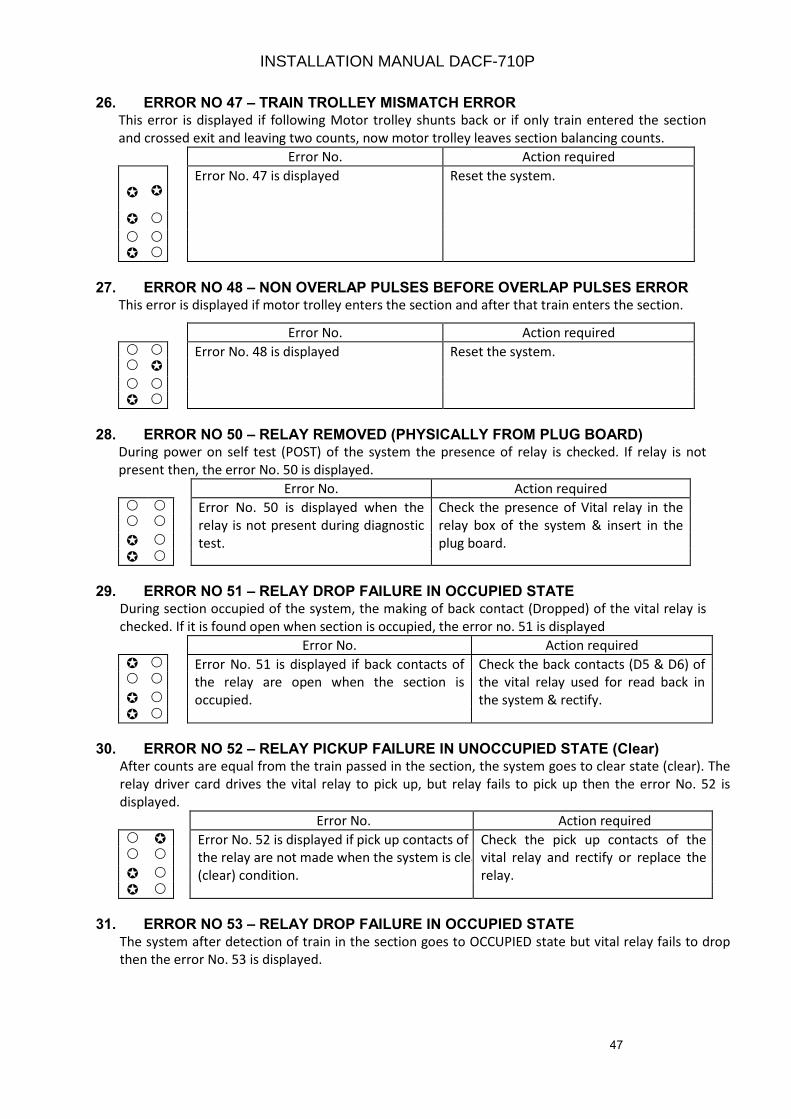
47
26. ERROR NO 47 – TRAIN TROLLEY MISMATCH ERRORThis error is displayed if following Motor trolley shunts back or if only train entered the section
and crossed exit and leaving two counts, now motor trolley leaves section balancing counts.
Error No. Action required
Error No. 47 is displayed Reset the system.
27. ERROR NO 48 – NON OVERLAP PULSES BEFORE OVERLAP PULSES ERRORThis error is displayed if motor trolley enters the section and after that train enters the section.
Error No. Action required
Error No. 48 is displayed Reset the system.
28. ERROR NO 50 – RELAY REMOVED (PHYSICALLY FROM PLUG BOARD)During power on self test (POST) of the system the presence of relay is checked. If relay is not
present then, the error No. 50 is displayed.
Error No. Action required
Error No. 50 is displayed when the
relay is not present during diagnostic
test.
Check the presence of Vital relay in the
relay box of the system & insert in the
plug board.
29. ERROR NO 51 – RELAY DROP FAILURE IN OCCUPIED STATEDuring section occupied of the system, the making of back contact (Dropped) of the vital relay is
checked. If it is found open when section is occupied, the error no. 51 is displayed
Error No. Action required
Error No. 51 is displayed if back contacts of
the relay are open when the section is
occupied.
Check the back contacts (D5 & D6) of
the vital relay used for read back in
the system & rectify.
30. ERROR NO 52 – RELAY PICKUP FAILURE IN UNOCCUPIED STATE (Clear)After counts are equal from the train passed in the section, the system goes to clear state (clear). The
relay driver card drives the vital relay to pick up, but relay fails to pick up then the error No. 52 is
displayed.
Error No. Action required
Error No. 52 is displayed if pick up contacts of
the relay are not made when the system is clear
(clear) condition.
Check the pick up contacts of the
vital relay and rectify or replace the
relay.
31. ERROR NO 53 – RELAY DROP FAILURE IN OCCUPIED STATE
The system after detection of train in the section goes to OCCUPIED state but vital relay fails to drop
then the error No. 53 is displayed.
INSTALLATION MANUAL DACF-710P
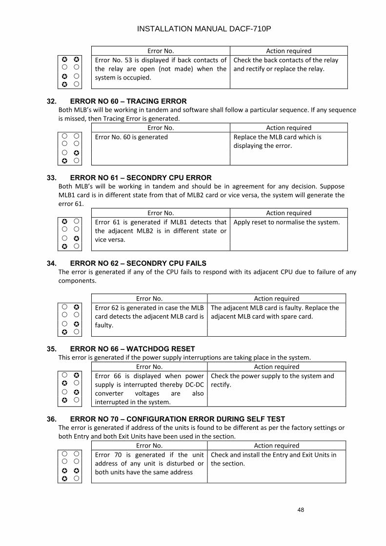
48
Error No. Action required
Error No. 53 is displayed if back contacts of
the relay are open (not made) when the
system is occupied.
Check the back contacts of the relay
and rectify or replace the relay.
32. ERROR NO 60 – TRACING ERRORBoth MLB’s will be working in tandem and software shall follow a particular sequence. If any sequence
is missed, then Tracing Error is generated.
Error No. Action required
Error No. 60 is generated Replace the MLB card which is
displaying the error.
33. ERROR NO 61 – SECONDRY CPU ERRORBoth MLB’s will be working in tandem and should be in agreement for any decision. Suppose
MLB1 card is in different state from that of MLB2 card or vice versa, the system will generate the
error 61.
Error No. Action required
Error 61 is generated if MLB1 detects that
the adjacent MLB2 is in different state or
vice versa.
Apply reset to normalise the system.
34. ERROR NO 62 – SECONDRY CPU FAILSThe error is generated if any of the CPU fails to respond with its adjacent CPU due to failure of any
components.
Error No. Action required
Error 62 is generated in case the MLB
card detects the adjacent MLB card is
faulty.
The adjacent MLB card is faulty. Replace the
adjacent MLB card with spare card.
35. ERROR NO 66 – WATCHDOG RESETThis error is generated if the power supply interruptions are taking place in the system.
Error No. Action required
Error 66 is displayed when power
supply is interrupted thereby DC-DC
converter voltages are also
interrupted in the system.
Check the power supply to the system and
rectify.
36. ERROR NO 70 – CONFIGURATION ERROR DURING SELF TESTThe error is generated if address of the units is found to be different as per the factory settings or
both Entry and both Exit Units have been used in the section.
Error No. Action required
Error 70 is generated if the unit
address of any unit is disturbed or
both units have the same address
Check and install the Entry and Exit Units in
the section.
INSTALLATION MANUAL DACF-710P
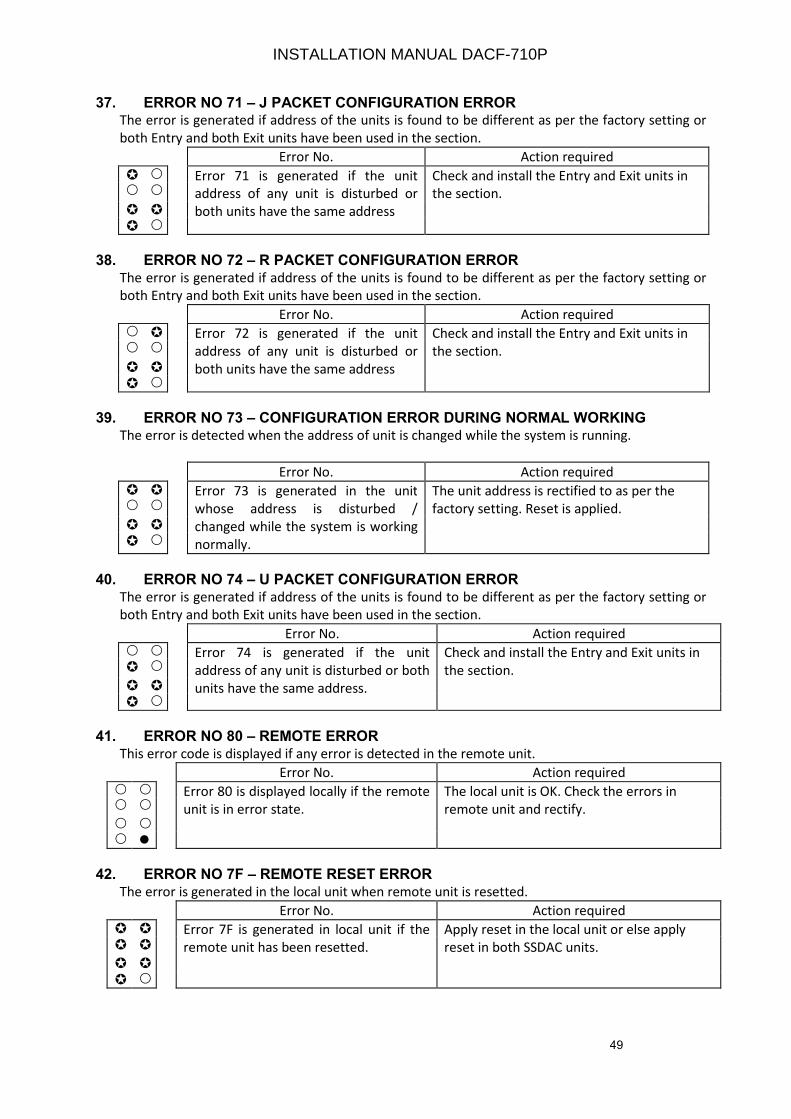
49
37. ERROR NO 71 – J PACKET CONFIGURATION ERRORThe error is generated if address of the units is found to be different as per the factory setting or
both Entry and both Exit units have been used in the section.
Error No. Action required
Error 71 is generated if the unit
address of any unit is disturbed or
both units have the same address
Check and install the Entry and Exit units in
the section.
38. ERROR NO 72 – R PACKET CONFIGURATION ERROR
The error is generated if address of the units is found to be different as per the factory setting or
both Entry and both Exit units have been used in the section.
Error No. Action required
Error 72 is generated if the unit
address of any unit is disturbed or
both units have the same address
Check and install the Entry and Exit units in
the section.
39. ERROR NO 73 – CONFIGURATION ERROR DURING NORMAL WORKING
The error is detected when the address of unit is changed while the system is running.
Error No. Action required
Error 73 is generated in the unit
whose address is disturbed /
changed while the system is working
normally.
The unit address is rectified to as per the
factory setting. Reset is applied.
40. ERROR NO 74 – U PACKET CONFIGURATION ERROR
The error is generated if address of the units is found to be different as per the factory setting or
both Entry and both Exit units have been used in the section.
Error No. Action required
Error 74 is generated if the unit
address of any unit is disturbed or both
units have the same address.
Check and install the Entry and Exit units in
the section.
41. ERROR NO 80 – REMOTE ERROR
This error code is displayed if any error is detected in the remote unit.
Error No. Action required
Error 80 is displayed locally if the remote
unit is in error state.
The local unit is OK. Check the errors in
remote unit and rectify.
42. ERROR NO 7F – REMOTE RESET ERROR
The error is generated in the local unit when remote unit is resetted.
Error No. Action required
Error 7F is generated in local unit if the
remote unit has been resetted.
Apply reset in the local unit or else apply
reset in both SSDAC units.
INSTALLATION MANUAL DACF-710P
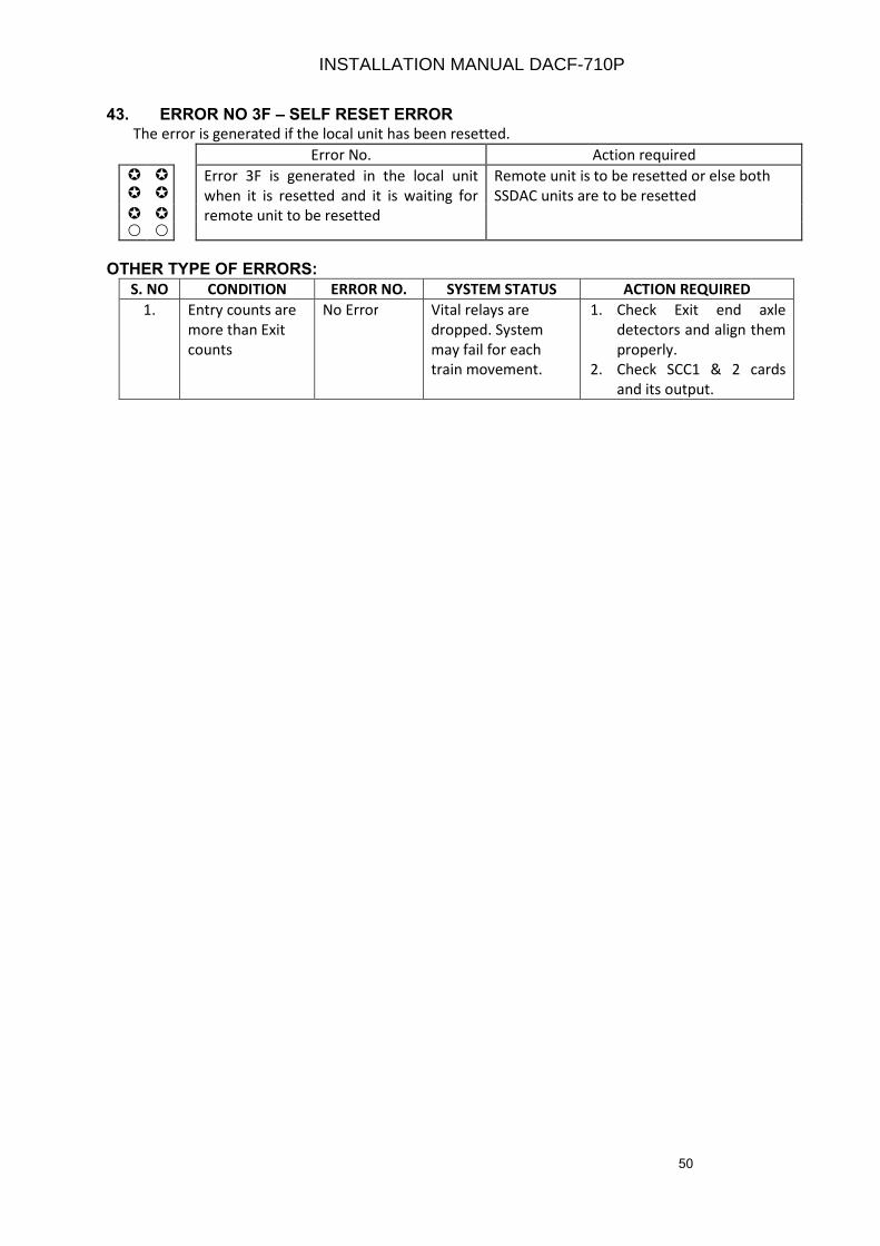
50
43. ERROR NO 3F – SELF RESET ERRORThe error is generated if the local unit has been resetted.
Error No. Action required
Error 3F is generated in the local unit
when it is resetted and it is waiting for
remote unit to be resetted
Remote unit is to be resetted or else both
SSDAC units are to be resetted
OTHER TYPE OF ERRORS:
S. NO CONDITION ERROR NO. SYSTEM STATUS ACTION REQUIRED
1. Entry counts are
more than Exit
counts
No Error Vital relays are
dropped. System
may fail for each
train movement.
1. Check Exit end axle
detectors and align them
properly.
2. Check SCC1 & 2 cards
and its output.
INSTALLATION MANUAL DACF-710P
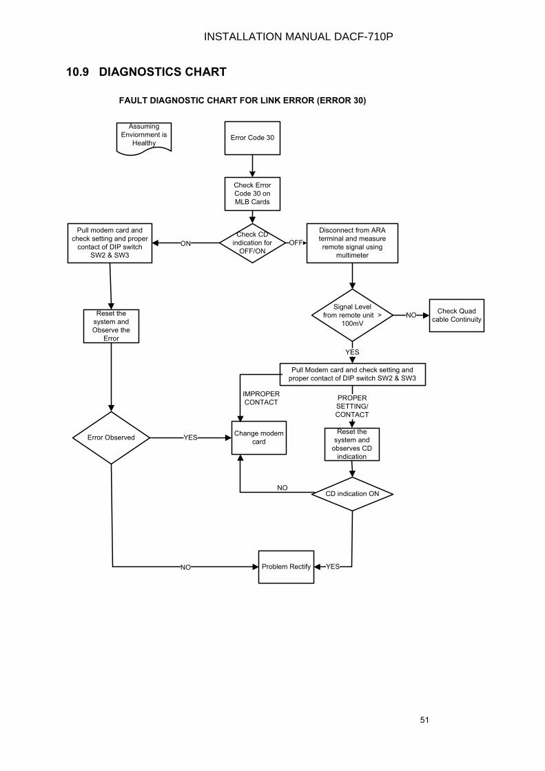
51
10.9 DIAGNOSTICS CHART
Assuming
Enviornment is
HealthyError Code 30
Check Error
Code 30 on
MLB Cards
Check CD
indication for
OFF/ON
Disconnect from ARA
terminal and measure
remote signal using
multimeter
OFF
Signal Level
from remote unit >
100mV
NOCheck Quad
cable Continuity
Pull Modem card and check setting and
proper contact of DIP switch SW2 & SW3
YES
PROPER SETTING/CONTACT
Reset the
system and
observes CD
indication
CD indication ON
Problem Rectify YES
Error ObservedChange modem
card
IMPROPER
CONTACT
ON
YES
Pull modem card and
check setting and proper
contact of DIP switch
SW2 & SW3
NO
Reset the
system and
Observe the
Error
NO
FAULT DIAGNOSTIC CHART FOR LINK ERROR (ERROR 30)
INSTALLATION MANUAL DACF-710P

52
INSTALLATION MANUAL DACF-710P
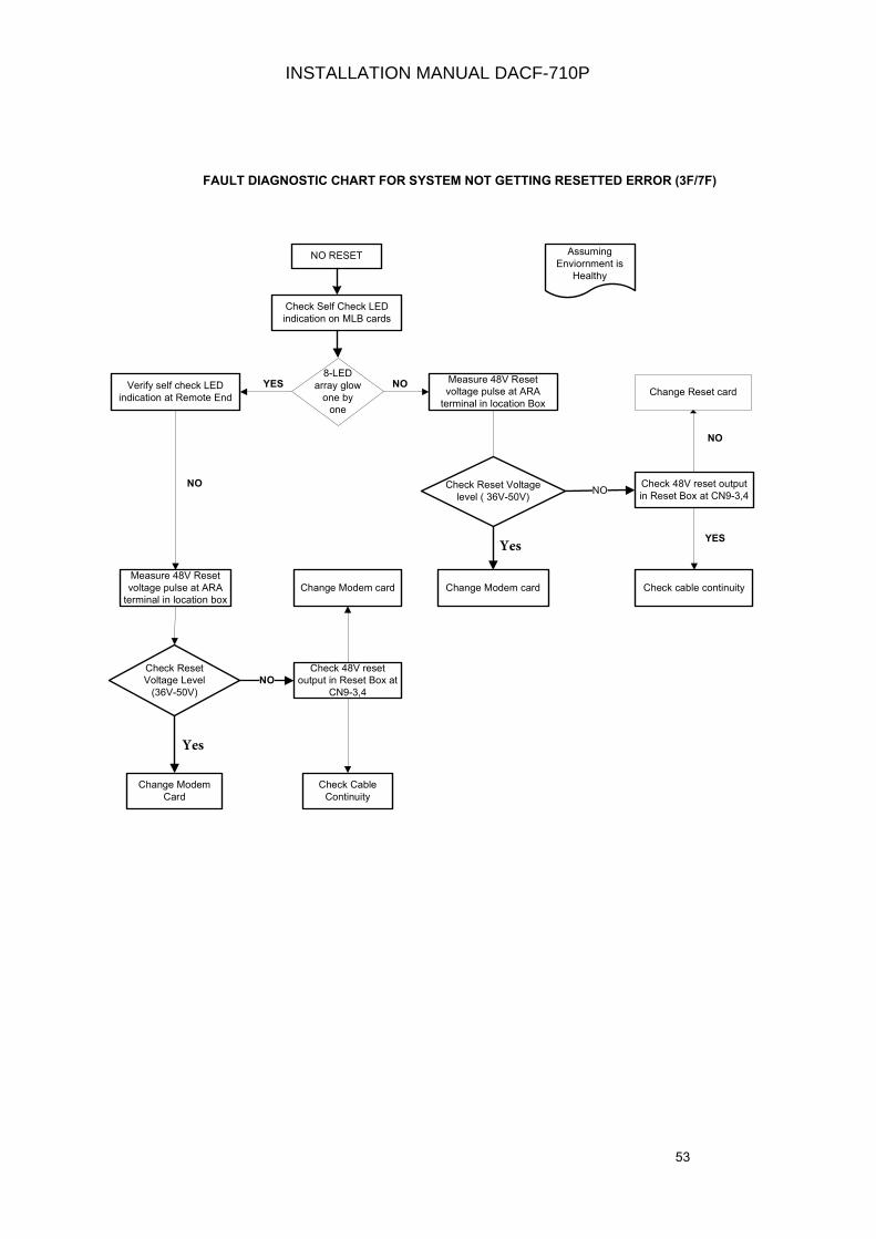
53
Assuming
Enviornment is
Healthy
NO RESET
Check Self Check LED
indication on MLB cards
Check Reset Voltage
level ( 36V-50V)NO
Check 48V reset output
in Reset Box at CN9-3,4
Change Modem card
Change Modem
Card
Check Reset
Voltage Level
(36V-50V)
FAULT DIAGNOSTIC CHART FOR SYSTEM NOT GETTING RESETTED ERROR (3F/7F)
Change Modem card
NO
Check 48V reset
output in Reset Box at
CN9-3,4
Check Cable
Continuity
8-LED
array glow
one by
one
Measure 48V Reset
voltage pulse at ARA
terminal in location Box
Verify self check LED
indication at Remote EndChange Reset card
Check cable continuity
YES NO
Measure 48V Reset
voltage pulse at ARA
terminal in location box
NO
YES
NO
INSTALLATION MANUAL DACF-710P
Yes
Yes
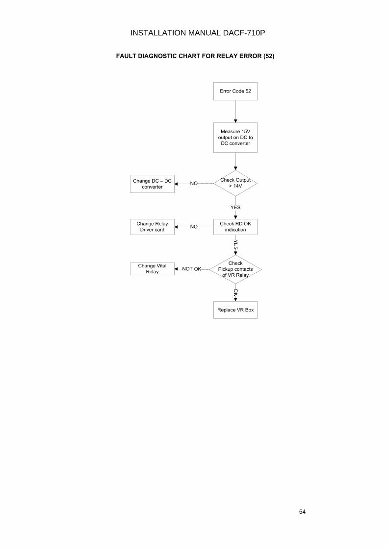
54
Error Code 52
Measure 15V
output on DC to
DC converter
Check Output
> 14VChange DC – DC
converter
Check RD OK
indication
Check
Pickup contacts
of VR Relay
Change Relay
Driver card
Change Vital
Relay
Replace VR Box
NO
NO
NOT OK
YES
FAULT DIAGNOSTIC CHART FOR RELAY ERROR (52)
INSTALLATION MANUAL DACF-710P

55
CHAPTER 11
11.0 EARTHING
11.1 EARTHING OF SSDAC
The Earth Electrode and its details of installation are shown in Drg. No. I007755A4 (Page No.
D30) and shall normally consist of one or more galvanized iron pipes of not less than 38 mm
internal diameter and not less than 2.5 mtr. in length with spike at one end and a lug at the
other end for connecting with earth lead. The pipe is embedded vertically, leaving the portion
above the ground.
11.2 TREATMENT OF SOIL
i. To reduce the resistivity of the soil, it is necessary to absorb and retain the moisture normally
contained in the soil. For this purpose, “Earth resistance improvement material” procured
from RDSO recommended firms should be used. Instructions given by manufacturer/supplier
of this item should be followed to get its full advantage and maintenance free earth.
ii. The Earthing arrangement should be located in the natural soil, as far as possible. The made
up soil is likely to result in poor earthing and may be eroded by weather and is not suitable.
11.3 EARTH LEAD WIRES
The lead wires connecting the installation and the earth electrode shall ordinarily be of
stranded copper wire of 29 sq. mm (19 strand wires of 1.4 mm diameter). Copper wire has
been specified because GI wires usually are having greater corrosion. However, in areas where
copper wire may be frequently stolen due to theft, ACSR of size 64 sq. mm (19 strands of 2.11
mm diameter) may be used.
11.4 LIMITS OF EARTH RESISTANCE
The maximum values of earth resistance specified for Earthing of SSDAC and its accessories
are as follows
S.No Value
1 i. Apparatus case connected to Earth (SSDAC and vital Relay Box is
housed in Apparatus case and Connected to earth at outdoor.)
ii. All cable connected to same earth
< 1 ohms
2 Reset box connected to earth (Indoor) near SM’s Room. < 1 ohms
INSTALLATION MANUAL DACF-710P
56
11.5 EQUIPMENT TO BE EARTHED
A Common Earth should be provided for SSDAC for items 1 (i & ii) of the above at the
outdoor
i. The Apparatus Case is to be connected to earth (the chassis of SSDAC & Vital Relay Box
should be properly connected to apparatus case).
ii. Metallic sheath and armouring of all the underground main cables are to be earthed
a. In R.E area, the metallic sheath and armouring of main telecom cables are earthed at
both ends.
b. In R.E area, the armouring of jelly filled cable shall be earthed at both ends.
iii. The Earthing shall be provided at every location box where cables are terminated.
iv. Earth already available for other equipment may be used for earthing of Reset Box near
SM’s Room / Cabin etc.
11.6 PRECAUTIONS TO BE TAKEN DURING EARTHING
i. The earth electrodes shall be free from paint, enamel or grease.
ii. Under ordinary condition of soil, G.I or M.S electrode is used.
iii. In areas where corrosion is likely to be excessive, it is preferable to use either copper or
copper clad electrode.
iv. The length of electrode should be of minimum 2.5m length.
v. When a rocky area is encountered at a depth of less than 2m, the electrode may be buried
inclined with the inclination being limited to 30° from vertical.
vi. The diameter of earth electrode is such that it can easily withstand the strain of driving in
rocky areas.
vii. The earth lead should be of adequate size to offer negligible resistance.
viii. In case, the earth lead wire is buried underground, it should be protected from corrosion
by an application of suitable anti-corrosive paint or bitumen or varnish.
ix. Where the earthing arrangement for other equipment is required in railways, the distance
between earthing electrodes shall not be less than 2m.
x. The Earth leads for separate earthing arrangements should be electrically insulated from
each other throughout and also from metallic structures in contact with the different
earthing arrangements.
xi. The minimum clearance of equipment earths provided by the electrical department (RE) of
the Railways or of the other administration should be 20 meters away from SSDAC Axle
Counter earth.
INSTALLATION MANUAL DACF-710P

57
xii. In places where the soil is extensively corrosive, the soil may be chemically examined
before deciding the material of the earth electrode.
xiii. The earth wire should be soldered to the screen/armouring and securely connected to the
earth electrode.
11.7 MAINTENANCE AND TESTING OF EARTHS
I. All earth connections should be examined at an interval of not more than one month, to
ensure that all connections are intact and soldered joints are in proper condition.
II. Resistance of every earth should be measured at an interval not exceeding one year. Earth
Resistance, date of last test and location of earth should be entered in the register/ signal
failures register. Earth resistance and date of testing should also be painted on the wall of a
nearby structure post at a convenient place.
INSTALLATION MANUAL DACF-710P
58
CHAPTER 12
12.0 SURGE VOLTAGE AND LIGHTNING PROTECTION
12.1 INTRODCUTION
Transient surge voltages arise as a result of Lightning discharge, switching operations in
electrical systems and electrostatic discharge. These surge voltages often destroy the
electronic equipment to a large extent.
12.2 CAUSES OF SURGE VOLTAGE IN POWER AND DATA LINES
The coupling of surge voltages from one system to another system can be Galvanic,
inductive or capacitive. The three types of coupling are explained here using the example
of lightning discharge.
Galvanic Discharge
High Lightning current amplitudes cause a surge voltage at the grounding resistance, which
in turn couples into the connected lines via equipotential bus bar.
Inductive Coupling
Inductive coupling into a conductor occurs through the magnetic field of another current
carrying conductor, following transformer principle.
Capacitive Coupling
Capacitive coupling always occurs via the electric field between two points with a high
potential difference.
12.3 PROTECTION OF SSDAC FROM SURGE VOLTAGES
In order to prevent surge voltages from destroying the equipment, all the input lines of
SSDAC i.e. Power Supply (24V), Reset (48V) & both the Modem lines i.e. SSDAC to SSDAC &
SSDAC to reset box is to be routed through surge voltage protection devices for effectively
protecting the system.
These devices (6 numbers) are mounted in a box and supplied along with the system (as
per drawing no A008427A4, page no D31). One number of SVPD box is to be installed at
each location and wired to the SSDAC (as per drawing no. W008556A4, page no D32 &
D33).
INSTALLATION MANUAL DACF-710P

59
In addition to these surge modules, added protection is given for input 24V line that acts as
a filter for 24V DC. It helps in filtering out the surge entering in the system during
changeovers etc.
12.4 WIRING DETAILS OF SURGE VOLTAGE DEVICE
SVPD unit is supplied by two types of protection devices. The wiring details of each type
are to be done as per supplied item.
Currently CEL supplies two types of Surge devices. OBO make & Phoenix make. The wiring
details of each of these devices are required to be done as per drawing enclosed.
OBO make
For these devices, kindly refer to the drawing no W008556A on page D32.
Phoenix make
For these devices, kindly refer to the drawing no W008556A on page D33.
Note It is recommended to use as shorter wire as possible for connections and earthing to these
devices for better protection. In case of lightening, Do replace these modules in case of its damage
due to lightening with fresh modules
INSTALLATION MANUAL DACF-710P
60
CHAPTER 13
13.0 SM's RESET BOX
(Drawing no F008443A4, Page No. D16 & W008444A4, Page No. D17)
The reset box is a tabletop model has been designed as per RDSO Drawing No S/2000/3. It has
the following components
1. The LED indications displaying the section status
a. Section Clear green indication LED of 10mm.
b. Section Occupied Red indication LED of 10mm.
c. Power ON Yellow indication of 3mm.
d. Prep. Reset Green indication of 3mm.
e. Line Verif. Yellow indication of 3mm.
2. SM’s Key actuator
3. Push Button Red colour
4. Counter for recording the number of reset operations.
5. 20 X 2 LCD display with Backlit
6. 4 Keys Keypad for setting the date and time operation.
7. 9 pin D-sub connector is given on the back panel of reset box which can be used for
downloading the data from flash for analysis purpose.
8. Miniature reset switch for refreshing the LCD display.
13.1. FEATURES OF RESET BOX
The new reset box (RB-259) supplied by SSDAC consists of two cards.
Card 1 of reset box is Interface card or controller block which is plugged in ECN2 connector of
motherboard.
i. This interface card is used to provide interface with the SSDAC unit on a pair of cable (2
wire of Quad is preferred).This communication from reset box and SSDAC unit is used for
transmission of packets from SSDAC to the reset box. These packets are then processed in
the reset box to display the information in the form of Axle Counts and Error Code of both
local unit and remote unit.
ii. It has onboard flash memory which stores the serial packets of the local unit. In order to
analyse the local SSDAC packets, this data can be downloaded from the flash by using any
windows compatible PC.
INSTALLATION MANUAL DACF-710P
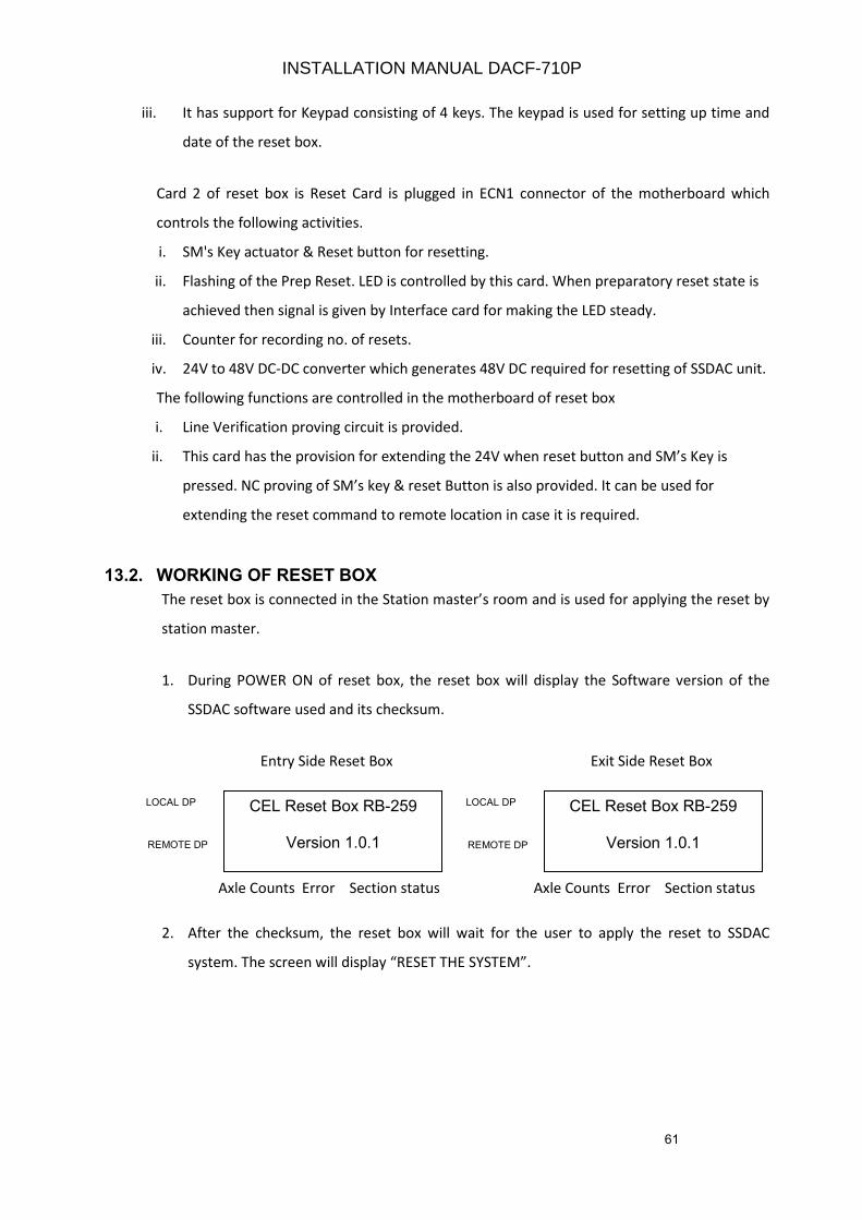
61
iii. It has support for Keypad consisting of 4 keys. The keypad is used for setting up time and
date of the reset box.
Card 2 of reset box is Reset Card is plugged in ECN1 connector of the motherboard which
controls the following activities.
i. SM's Key actuator & Reset button for resetting.
ii. Flashing of the Prep Reset. LED is controlled by this card. When preparatory reset state is
achieved then signal is given by Interface card for making the LED steady.
iii. Counter for recording no. of resets.
iv. 24V to 48V DC-DC converter which generates 48V DC required for resetting of SSDAC unit.
The following functions are controlled in the motherboard of reset box
i. Line Verification proving circuit is provided.
ii. This card has the provision for extending the 24V when reset button and SM’s Key is
pressed. NC proving of SM’s key & reset Button is also provided. It can be used for
extending the reset command to remote location in case it is required.
13.2. WORKING OF RESET BOX
The reset box is connected in the Station master’s room and is used for applying the reset by
station master.
1. During POWER ON of reset box, the reset box will display the Software version of the
SSDAC software used and its checksum.
Entry Side Reset Box Exit Side Reset Box
Axle Counts Error Section status Axle Counts Error Section status
2. After the checksum, the reset box will wait for the user to apply the reset to SSDAC
system. The screen will display “RESET THE SYSTEM”.
CEL Reset Box RB-259
Version 1.0.1
LOCAL DP
REMOTE DP
CEL Reset Box RB-259
Version 1.0.1
LOCAL DP
REMOTE DP
INSTALLATION MANUAL DACF-710P
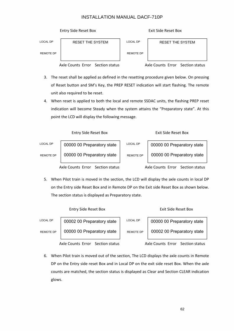
62
Entry Side Reset Box Exit Side Reset Box
Axle Counts Error Section status Axle Counts Error Section status
3. The reset shall be applied as defined in the resetting procedure given below. On pressing
of Reset button and SM’s Key, the PREP RESET indication will start flashing. The remote
unit also required to be reset.
4. When reset is applied to both the local and remote SSDAC units, the flashing PREP reset
indication will become Steady when the system attains the “Preparatory state”. At this
point the LCD will display the following message.
Entry Side Reset Box Exit Side Reset Box
Axle Counts Error Section status Axle Counts Error Section status
5. When Pilot train is moved in the section, the LCD will display the axle counts in local DP
on the Entry side Reset Box and in Remote DP on the Exit side Reset Box as shown below.
The section status is displayed as Preparatory state.
Entry Side Reset Box Exit Side Reset Box
Axle Counts Error Section status Axle Counts Error Section status
6. When Pilot train is moved out of the section, The LCD displays the axle counts in Remote
DP on the Entry side reset Box and in Local DP on the exit side reset Box. When the axle
counts are matched, the section status is displayed as Clear and Section CLEAR indication
glows.
RESET THE SYSTEM LOCAL DP
REMOTE DP
RESET THE SYSTEM LOCAL DP
REMOTE DP
00000 00 Preparatory state
00000 00 Preparatory state
LOCAL DP
REMOTE DP
00000 00 Preparatory state
00000 00 Preparatory state
LOCAL DP
REMOTE DP
00002 00 Preparatory state
00000 00 Preparatory state
LOCAL DP
REMOTE DP
00000 00 Preparatory state
00002 00 Preparatory state
LOCAL DP
REMOTE DP
INSTALLATION MANUAL DACF-710P
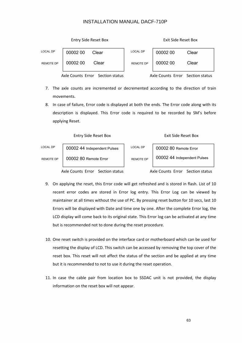
63
Entry Side Reset Box Exit Side Reset Box
Axle Counts Error Section status Axle Counts Error Section status
7. The axle counts are incremented or decremented according to the direction of train
movements.
8. In case of failure, Error code is displayed at both the ends. The Error code along with its
description is displayed. This Error code is required to be recorded by SM’s before
applying Reset.
Entry Side Reset Box Exit Side Reset Box
Axle Counts Error Section status Axle Counts Error Section status
9. On applying the reset, this Error code will get refreshed and is stored in flash. List of 10
recent error codes are stored in Error log entry. This Error Log can be viewed by
maintainer at all times without the use of PC. By pressing reset button for 10 secs, last 10
Errors will be displayed with Date and time one by one. After the complete Error log, the
LCD display will come back to its original state. This Error log can be activated at any time
but is recommended not to done during the reset procedure.
10. One reset switch is provided on the interface card or motherboard which can be used for
resetting the display of LCD. This switch can be accessed by removing the top cover of the
reset box. This reset will not affect the status of the section and be applied at any time
but it is recommended to not to use it during the reset operation.
11. In case the cable pair from location box to SSDAC unit is not provided, the display
information on the reset box will not appear.
00002 00 Clear
00002 00 Clear
LOCAL DP
REMOTE DP
00002 00 Clear
00002 00 Clear
LOCAL DP
REMOTE DP
00002 44 Independent Pulses
00002 80 Remote Error
LOCAL DP
REMOTE DP
00002 80 Remote Error
00002 44 Independent Pulses
LOCAL DP
REMOTE DP
INSTALLATION MANUAL DACF-710P
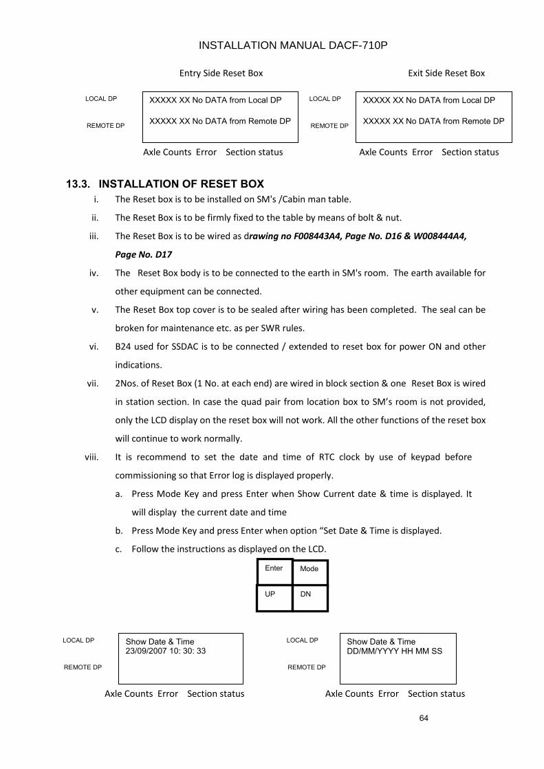
64
13.3. INSTALLATION OF RESET BOX
i. The Reset box is to be installed on SM's /Cabin man table.
ii. The Reset Box is to be firmly fixed to the table by means of bolt & nut.
iii. The Reset Box is to be wired as drawing no F008443A4, Page No. D16 & W008444A4,
Page No. D17
iv. The Reset Box body is to be connected to the earth in SM's room. The earth available for
other equipment can be connected.
v. The Reset Box top cover is to be sealed after wiring has been completed. The seal can be
broken for maintenance etc. as per SWR rules.
vi. B24 used for SSDAC is to be connected / extended to reset box for power ON and other
indications.
vii. 2Nos. of Reset Box (1 No. at each end) are wired in block section & one Reset Box is wired
in station section. In case the quad pair from location box to SM’s room is not provided,
only the LCD display on the reset box will not work. All the other functions of the reset box
will continue to work normally.
viii. It is recommend to set the date and time of RTC clock by use of keypad before
commissioning so that Error log is displayed properly.
a. Press Mode Key and press Enter when Show Current date & time is displayed. It
will display the current date and time
b. Press Mode Key and press Enter when option “Set Date & Time is displayed.
c. Follow the instructions as displayed on the LCD.
Entry Side Reset Box Exit Side Reset Box
Axle Counts Error Section status Axle Counts Error Section status
Axle Counts Error Section status Axle Counts Error Section status
XXXXX XX No DATA from Local DP
XXXXX XX No DATA from Remote DP
LOCAL DP
REMOTE DP
XXXXX XX No DATA from Local DP
XXXXX XX No DATA from Remote DP
LOCAL DP
REMOTE DP
Enter Mode
UP DN
Show Date & Time 23/09/2007 10: 30: 33
LOCAL DP
REMOTE DP
Show Date & Time DD/MM/YYYY HH MM SS
LOCAL DP
REMOTE DP
INSTALLATION MANUAL DACF-710P
65
13.4 RESETTING PROCEDURE
13.4.1 SSDAC WHEN USED FOR TRACK CIRCUITING AT STATIONS
• COMMON RESETTING
The common resetting of both SSDAC units is to be carried out when used for track
circuiting such as platform lines, yard lines etc. The provision for LV proving is also
provided for its use if required. Kindly refer drawing no S008429A3 on Page no. D18 for wiring
details
The design of reset box of modified SSDAC is such that the SM's Reset operation is
essential & absolutely necessary for carrying out the resetting in SSDAC. The Reset
operation is positive type & built in to the design of reset box & SSDAC using additional
hardware. The external Relays for resetting are not required. The danger of accidental
resetting in SSDAC due to power disconnection and reconnection is avoided with this type
of reset circuit.
• RESETTING OPERATION
1. i. Insert SM's key, turn right and keep pressed.
ii. Press Reset button for 3 to 5 seconds.
iii. Release SM's Key and Reset Button
iv. Turn left, remove SM's key and keep in safe custody.
2. With the above operation from step 1 (i) & (ii) the 48V DC from the reset box is extended
and connected to the SSDAC, the 48V DC activates the reset circuit in modem card (card 6)
of SSDAC unit and generates reset command to the Micro Controllers in MLB1 and MLB2
cards (Card 3 & 4)
3. Reset command to Microcontrollers will not be generated if system is in clear / preparatory
/ occupied state. System can be resetted if it is in error state or out counts were registered
after occupied state.
4. The SSDAC units are reset and counts become zero. The self test is carried out in both the
units. The SSDAC unit attains the preparatory reset state. The PR & PPR Relays pick up and
preparatory reset LED indication glows on the reset box in SM's room. Resetting operation
by both stations is required and is necessary in BPAC use.
5. The counter reading also increments by 1 count through the Prep. Reset command after a
gap of 5 sec. approximately. The counter reading should be recorded.
6. One pilot train is to be passed in the section to make the system normal. Thereafter, the
vital relay picks up.
INSTALLATION MANUAL DACF-710P
66
13.4.2 SSDAC WHEN USED IN BLOCK SECTIONS
• INDEPENDENT RESETTING
The independent resetting of SSDAC units at each station is to be carried out when used in
block sections. Sometime it may be required to prove the SM’s Key and Button and extend
24V for remote location for its use in railways circuit. Kindly refer drawing no S008429A3 on
Page no. D18 for wiring detail
The design of reset box of modified SSDAC is such that the SM's resetting operation from
both stations is essential and absolutely necessary for carrying out the resetting in SSDAC.
The Reset operation is positive type and built in to the design of reset box and SSDAC using
additional hardware. The external Relays for resetting are not required. The danger of
accidental resetting in SSDAC due to power disconnection and reconnection is avoided with
this type of resetting circuit.
• RESETTING OPERATION
Both sides resetting operation is required with or without time gap in BPAC use. The
procedure for resetting is as follows: -
1. i. Insert SM's key, turn right and keep pressed.
ii. Press Reset button for 3 to 5 secs
iii. Preparatory LED starts flashing.
iv. Release SM's Key and Reset Button
v. Turn left, remove SM's key and keep in safe custody.
2. With the above operation from step 1(I) & (ii) the 48V dc from the reset box is extended and
connected to the SSDAC, this 48V DC activates the reset circuit in modem card (card 6) of
SSDAC unit and generates reset command to the Micro Controllers in MLB 1 and MLB2 cards
(Card 3 & 4).
3 Reset command to Microcontrollers will not be generated if system is in clear / preparatory /
occupied state. System can be resetted if it is in error state or out counts were registered
after occupied state.
4. The SSDAC units are reset and counts become zero. The self-test is carried out in both the
units. The SSDAC units attain the preparatory reset state. The PR & PPR relays pick up and
preparatory reset LED indication glows on the reset box in SM's room. Resetting operation
by both stations is required and is necessary in BPAC use.
5. The counter reading also increments by 1 count through the Prep. Reset command after a
gap of 5 sec approx. The counter reading should be recorded.
6. One pilot train is to be passed in the section to make the system normal. Thereafter, the vital
relay picks up at both stations.
INSTALLATION MANUAL DACF-710P
67
CHAPTER 14
14.0 COMMISSIONING OF SYSTEM
14.1 PRECOMMISSIONING CHECK OF THE SYSTEM
After installation of the system, the measurements as per pre-commissioning check list
given in Annexure III are taken and recorded. The readings should be within limits.
14.2 RESET BOX RB – 259
The reset box controls the Resetting of SSDAC units at site. The reset box also consists of
line (section) status i.e. clear/occupied indications. The wiring of reset box installed at
Station Master’s room cabin is to be checked and verified as per the wiring details of the
reset box given in Drawing no W007742A4 (Page No. D17) & S008433A3 (Page No D18
& D19)
14.3 SURGE VOLTAGE PROTECTION DEVICE SV-121
The Surge Voltage protection device is to be installed at each location along with every
SSDAC unit. Each device is to be wired as per wiring details given in Chapter 12.
14.4 COMMISSIONING INTO SIGNALLING CIRCUITS
Parallel working of the system should be done first. The system is to be commissioned in
the signalling circuits after watching its performance during the parallel operation for 3
to 4 days for train movements in the section. It is to be ensured that the system is
working satisfactorily before commissioning. After commissioning, it is to be further
observed that system is working satisfactorily for a few more days. The failure register
may be opened with the Station Master for record of resets in the system.
INSTALLATION MANUAL DACF-710P
68
CHAPTER 15
15.0 MAINTENANCE SCHEDULE (MONTHLY)
15.1 TX & RX COIL AXLE DETECTORS (At site)
i. Measure the TX coil (21 KHz & 23 KHz) signal levels and record them. These
measurements are to be tallied with the previous readings. These should be within the
specified limits and should not change more than ±10%.
ii. Measure the Rx coil (21 KHz & 23 KHz) signal levels and record them. These
measurements are to be tallied with the previous readings. These should be within the
specified limits and should not change more than ±10%.
iii. Check the M12 Bolts & Nuts of web mounted TX & Rx coil Axle detectors. All the nuts
should be in tight condition.
iv. Check and tighten the deflector plates if found loose.
15.2 SSDAC UNIT (At site)
i. The 2.2V DC signal levels of card 1&2 of the SSDAC Counting Units are measured and
recorded. The level should be between 2.0 to 2.5V DC.
ii. DC-DC converter output voltages should be measured and recorded. The outputs
measured should remain within the specified limits and match with the previous readings.
iii. The modem card output should be measured and recorded. The reading should match
with the previous readings
iv. Check the relay driver output and it should be >20 V DC. This reading is recorded.
v. Ensure that screws of modules are tight.
vi. Ensure that MS circular connectors are tight.
15.3 POWER SUPPLY (Battery Room & Site)
i. The 24V DC power supply should be measured and recorded. The 24V DC should remain
within specified limits.
ii. Inspect the battery charger and check its charging current and ensure it is properly
charging the battery.
iii. Any interference with power supply and connections of SSDAC is likely to cause failure.
This should be done only after ensuring that no train is occupying or approaching the
section.
INSTALLATION MANUAL DACF-710P
69
15.4 INSPECTION OF RESET BOX (SM’s room)
i. Monitor the reset box while the train is occupying the section. The occupied (red)
LED should be glowing.
ii. When the train clears the section, the clear LED (green) glows.
iii. The Reset to the system is controlled through the key actuator & Reset button of
reset box. This should not be disturbed.
iv. The LCD displays all the information regarding the system as given in Chapter 13.
15.5 GENERAL
I. Check all the cable connections on the CT board of apparatus case at both locations.
Ensure that these are in tight condition.
II. Check the deflector plates of the Axle detectors are in normal position. If found loose
this should be properly tightened.
15.6 REPAIR OF FAULTY CARDS
i. Before declaring any card is faulty, the fault should be analysed and confirmed.
ii. Repair of cards is a highly technical job and is not possible at site. Hence Railways
should not carry it out. The card should be sent to CEL for repair.
INSTALLATION MANUAL DACF-710P
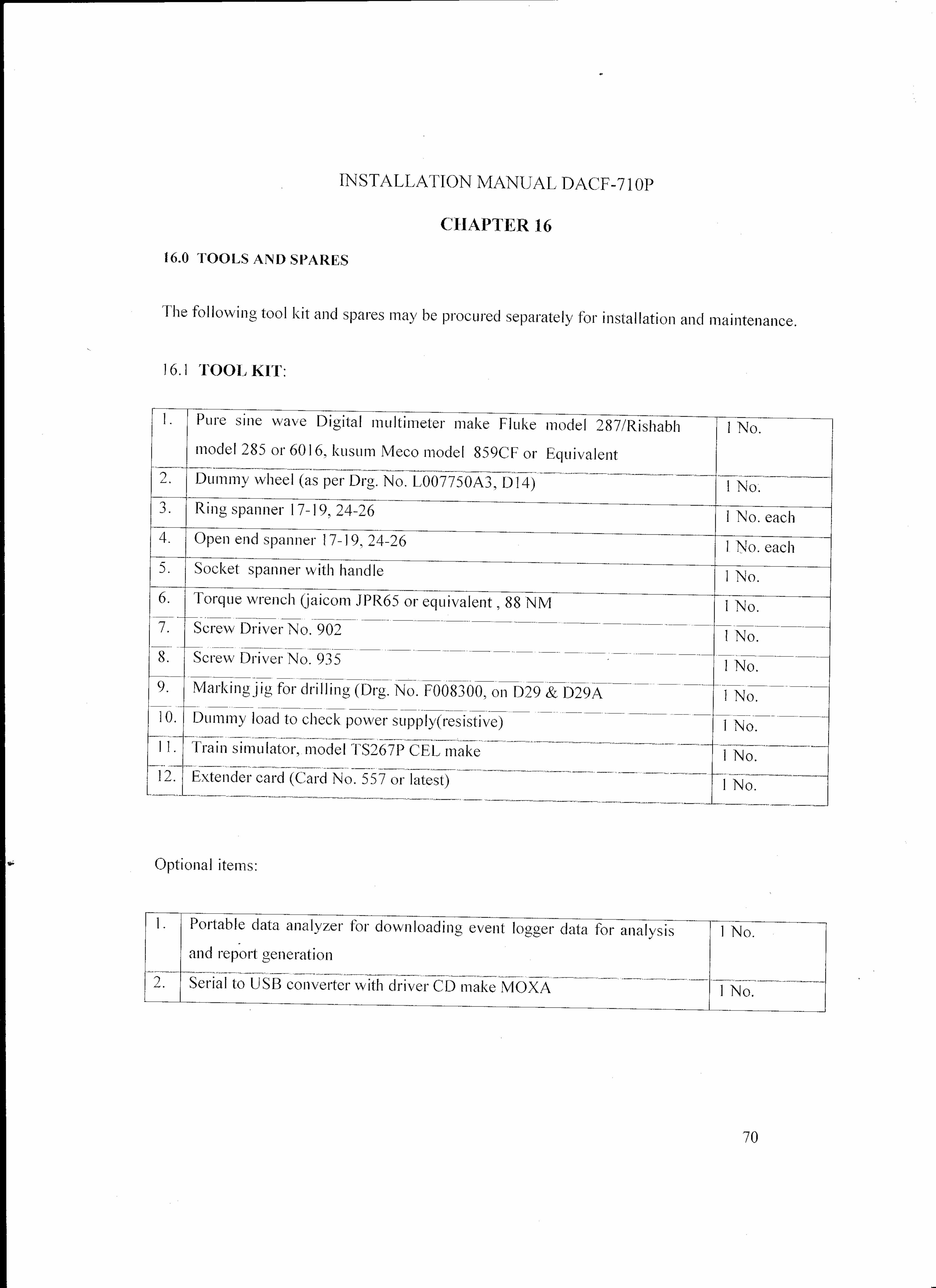
71
16.2 RECOMMENDED SPARES:
The following spares are to be procured separately for 5 nos. of Single Section Digital Axle Counter working in field
1. SCC 1&2 cards (Card 1 & 2) 2 Nos.
2. MLB 1&2 cards (Card 3 & 4) 2 Nos.
3. Modem card (Card 6) 1 No.
4. Relay driver (Card 7) 1 No.
5. Event Logger Card (Card 5) 2 Nos.
6. DC-DC converter (Card 8) 1 No.
7. Axle detectors (AD711) 21 KHz/23KHz (TX coil) 1 No.
8. Axle detectors (AD711) 21 KHz/ 23 KHz (Rx coil) 1 No.
9. Hardware for mounting axle detectors 1 Set
10. MS circular connectors (6 No.)consisting of 1 Set
a. MS1 – 7 pin – TX Coil – 1 each
b. MS2 – 5 pin – RX coil – 1 each
c. MS3 – 6 pin - Vital Relay – 1 each
d. MS4 – 4 pin – Modem – 1 each
e. MS5 – 9 pin – Monitor – 1 each
f. MS6 – 2 pin – DC Power – 1 each
11. Reset box RB-259 1 No.
12. SSDAC unit (housing with mother board, without cards) 1 No.
13. Vital Relay Box with Relay 24V, 1000 ohm, Q type 1 No.
14. Surge voltage protection device box (SV-121) 1 No.
INSTALLATION MANUAL DACF-710P
72
CHAPTER 17
17.0 DO’S AND DON’TS FOR DIGITAL AXLE COUNTER
17.1 DO’S
i. The inter connection drawings are to be followed for connecting the Transmitter & Receiver
coils. Tx1 is 21 KHz, Tx2 is 23 KHz & Rx1 and Rx2 coils are 21 KHz & 23 KHz, respectively.
ii. Ensure that Receiver and Transmitter coil cables have been laid in different pipes.
iii. Ensure that both the TX coils & Rx coils are having proper alignment on Rail.
iv. Ensure that packing of sleepers with ballast on both sides of Axle detector is proper.
v. Check that metal sheaths of the outdoor cable are connected to earth at both ends
vi. The recommended cables for wiring of the system at site should be used.
vii. The steady Battery voltage 24V should be maintained.
viii. The cable connections should not be connected loosely.
ix. The M.S Circular connectors of SSDAC are checked and maintained firmly.
x. The SSDAC & Reset box is provided with sealing arrangement. They should be sealed at site.
xi. Resetting should be done only after ensuring that there is no train in the section
17.2 Don’ts
i. Don’t install the Axle detectors near the rail joint (should be more than 6 sleepers away).
ii. Don’t install the Axle detectors where the rail is badly worn out.
iii. Don’t cut or join the Transmitter / Receiver cables supplied along with the coil. It would
result in change of frequency of signal.
iv. Don’t lay the TX and RX coil cables in the same pipe.
v. Don’t use any other outdoor cable other than the recommended cables.
vi. Avoid installing the Axle detectors on curve of rail / too much slope of rail to the possible
extent.
vii. Don’t remove the cards from SSDAC units under power ON condition of system.
viii. Remove card if necessary after Switching OFF the power to the unit.
INSTALLATION MANUAL DACF-710P
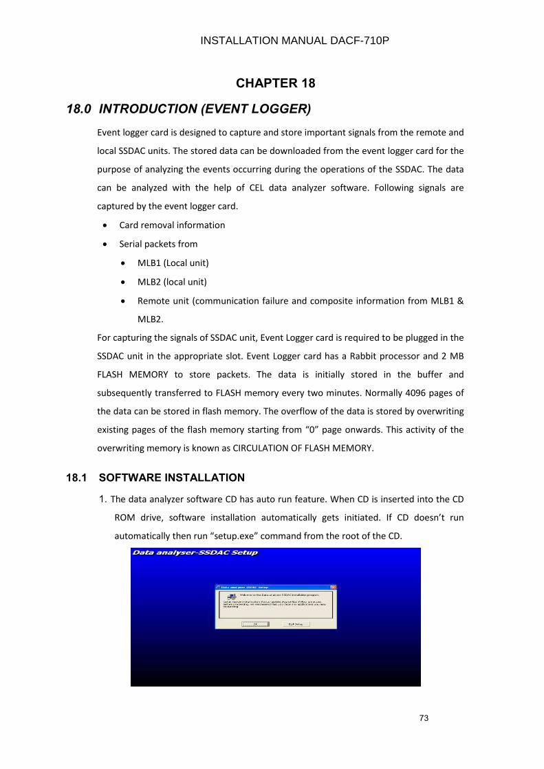
73
CHAPTER 18
18.0 INTRODUCTION (EVENT LOGGER)
Event logger card is designed to capture and store important signals from the remote and
local SSDAC units. The stored data can be downloaded from the event logger card for the
purpose of analyzing the events occurring during the operations of the SSDAC. The data
can be analyzed with the help of CEL data analyzer software. Following signals are
captured by the event logger card.
• Card removal information
• Serial packets from
• MLB1 (Local unit)
• MLB2 (local unit)
• Remote unit (communication failure and composite information from MLB1 &
MLB2.
For capturing the signals of SSDAC unit, Event Logger card is required to be plugged in the
SSDAC unit in the appropriate slot. Event Logger card has a Rabbit processor and 2 MB
FLASH MEMORY to store packets. The data is initially stored in the buffer and
subsequently transferred to FLASH memory every two minutes. Normally 4096 pages of
the data can be stored in flash memory. The overflow of the data is stored by overwriting
existing pages of the flash memory starting from “0” page onwards. This activity of the
overwriting memory is known as CIRCULATION OF FLASH MEMORY.
18.1 SOFTWARE INSTALLATION
1. The data analyzer software CD has auto run feature. When CD is inserted into the CD
ROM drive, software installation automatically gets initiated. If CD doesn’t run
automatically then run “setup.exe” command from the root of the CD.
INSTALLATION MANUAL DACF-710P
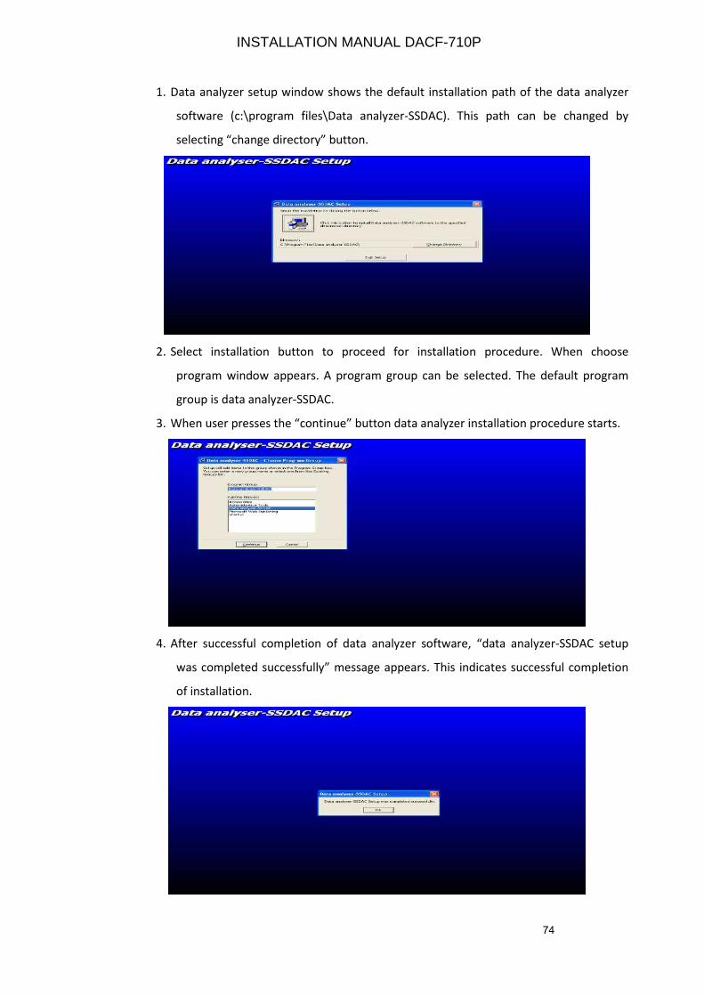
74
1. Data analyzer setup window shows the default installation path of the data analyzer
software (c:\program files\Data analyzer-SSDAC). This path can be changed by
selecting “change directory” button.
2. Select installation button to proceed for installation procedure. When choose
program window appears. A program group can be selected. The default program
group is data analyzer-SSDAC.
3. When user presses the “continue” button data analyzer installation procedure starts.
4. After successful completion of data analyzer software, “data analyzer-SSDAC setup
was completed successfully” message appears. This indicates successful completion
of installation.
INSTALLATION MANUAL DACF-710P
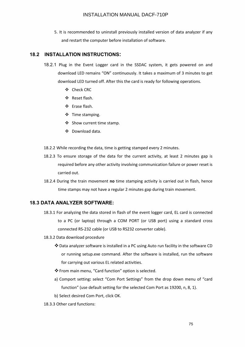
75
5. It is recommended to uninstall previously installed version of data analyzer if any
and restart the computer before installation of software.
18.2 INSTALLATION INSTRUCTIONS:
18.2.1 Plug in the Event Logger card in the SSDAC system, it gets powered on and
download LED remains “ON” continuously. It takes a maximum of 3 minutes to get
download LED turned off. After this the card is ready for following operations.
Check CRC
Reset flash.
Erase flash.
Time stamping.
Show current time stamp.
Download data.
18.2.2 While recording the data, time is getting stamped every 2 minutes.
18.2.3 To ensure storage of the data for the current activity, at least 2 minutes gap is
required before any other activity involving communication failure or power reset is
carried out.
18.2.4 During the train movement no time stamping activity is carried out in flash, hence
time stamps may not have a regular 2 minutes gap during train movement.
18.3 DATA ANALYZER SOFTWARE:
18.3.1 For analyzing the data stored in flash of the event logger card, EL card is connected
to a PC (or laptop) through a COM PORT (or USB port) using a standard cross
connected RS-232 cable (or USB to RS232 converter cable).
18.3.2 Data download procedure
Data analyzer software is installed in a PC using Auto run facility in the software CD
or running setup.exe command. After the software is installed, run the software
for carrying out various EL related activities.
From main menu, “Card function” option is selected.
a) Comport setting: select “Com Port Settings” from the drop down menu of “card
function” (use default setting for the selected Com Port as 19200, n, 8, 1).
b) Select desired Com Port, click OK.
18.3.3 Other card functions:
INSTALLATION MANUAL DACF-710P
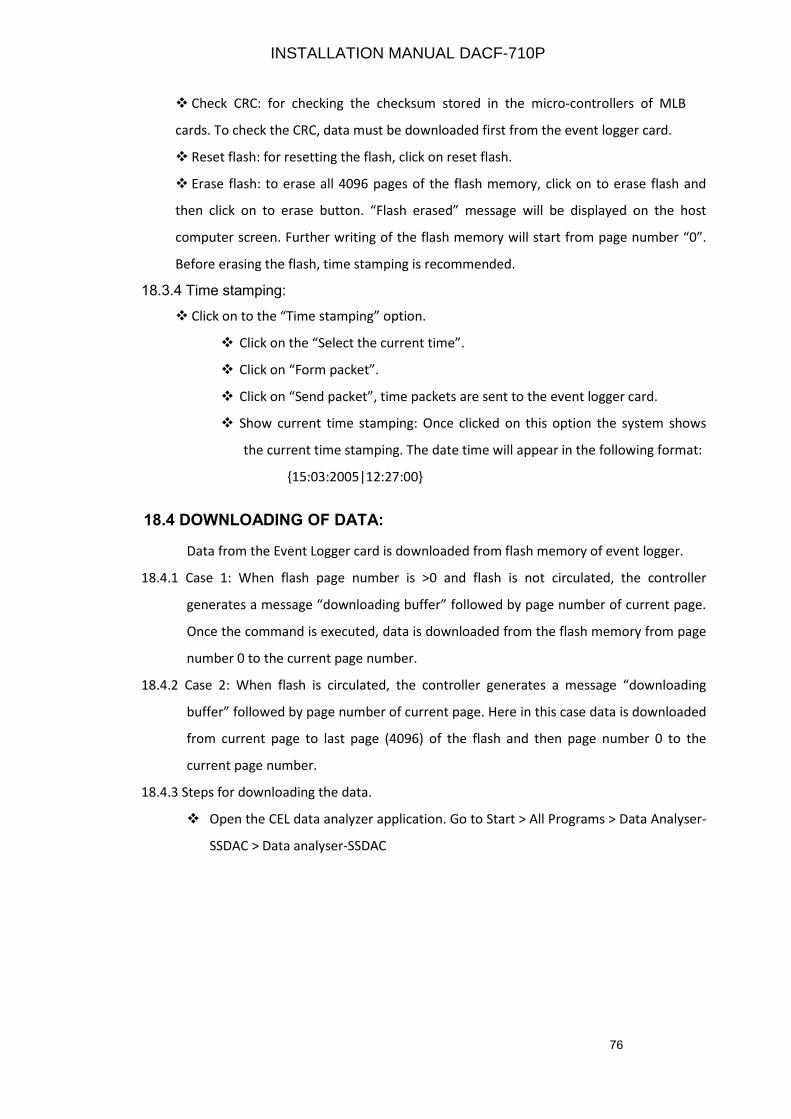
76
Check CRC: for checking the checksum stored in the micro-controllers of MLB
cards. To check the CRC, data must be downloaded first from the event logger card.
Reset flash: for resetting the flash, click on reset flash.
Erase flash: to erase all 4096 pages of the flash memory, click on to erase flash and
then click on to erase button. “Flash erased” message will be displayed on the host
computer screen. Further writing of the flash memory will start from page number “0”.
Before erasing the flash, time stamping is recommended.
18.3.4 Time stamping:
Click on to the “Time stamping” option.
Click on the “Select the current time”.
Click on “Form packet”.
Click on “Send packet”, time packets are sent to the event logger card.
Show current time stamping: Once clicked on this option the system shows
the current time stamping. The date time will appear in the following format:
15:03:2005|12:27:00
18.4 DOWNLOADING OF DATA:
Data from the Event Logger card is downloaded from flash memory of event logger.
18.4.1 Case 1: When flash page number is >0 and flash is not circulated, the controller
generates a message “downloading buffer” followed by page number of current page.
Once the command is executed, data is downloaded from the flash memory from page
number 0 to the current page number.
18.4.2 Case 2: When flash is circulated, the controller generates a message “downloading
buffer” followed by page number of current page. Here in this case data is downloaded
from current page to last page (4096) of the flash and then page number 0 to the
current page number.
18.4.3 Steps for downloading the data.
Open the CEL data analyzer application. Go to Start > All Programs > Data Analyser-
SSDAC > Data analyser-SSDAC
INSTALLATION MANUAL DACF-710P
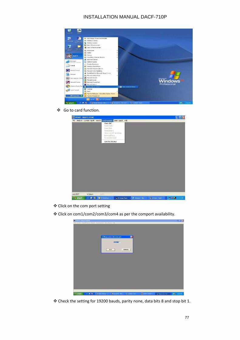
77
Go to card function.
Click on the com port setting
Click on com1/com2/com3/com4 as per the comport availability.
Check the setting for 19200 bauds, parity none, data bits 8 and stop bit 1.
INSTALLATION MANUAL DACF-710P
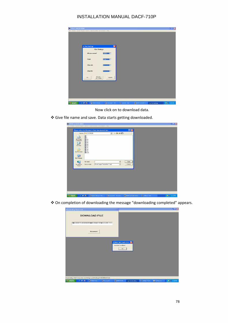
78
Now click on to download data.
Give file name and save. Data starts getting downloaded.
On completion of downloading the message “downloading completed” appears.
INSTALLATION MANUAL DACF-710P
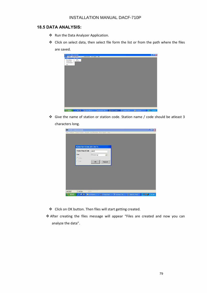
79
18.5 DATA ANALYSIS:
Run the Data Analyzer Application.
Click on select data, then select file form the list or from the path where the files
are saved.
Give the name of station or station code. Station name / code should be atleast 3
characters long.
Click on OK button. Then files will start getting created.
After creating the files message will appear “Files are created and now you can
analyze the data”.
INSTALLATION MANUAL DACF-710P
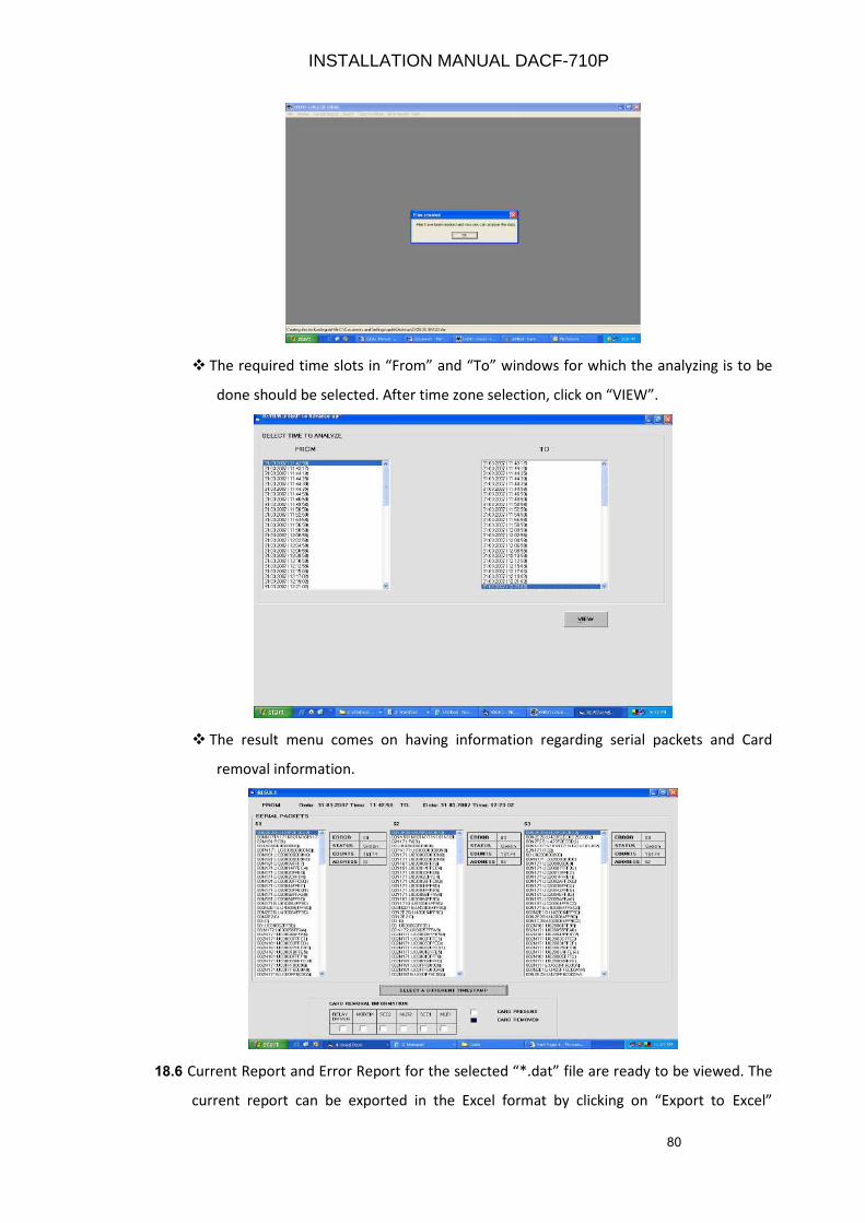
80
The required time slots in “From” and “To” windows for which the analyzing is to be
done should be selected. After time zone selection, click on “VIEW”.
The result menu comes on having information regarding serial packets and Card
removal information.
18.6 Current Report and Error Report for the selected “*.dat” file are ready to be viewed. The
current report can be exported in the Excel format by clicking on “Export to Excel”
INSTALLATION MANUAL DACF-710P
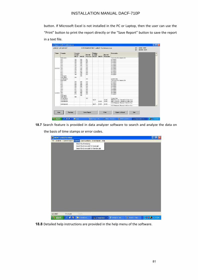
81
button. If Microsoft Excel is not installed in the PC or Laptop, then the user can use the
“Print” button to print the report directly or the “Save Report” button to save the report
in a text file.
18.7 Search feature is provided in data analyzer software to search and analyze the data on
the basis of time stamps or error codes.
18.8 Detailed help instructions are provided in the help menu of the software.
INSTALLATION MANUAL DACF-710P
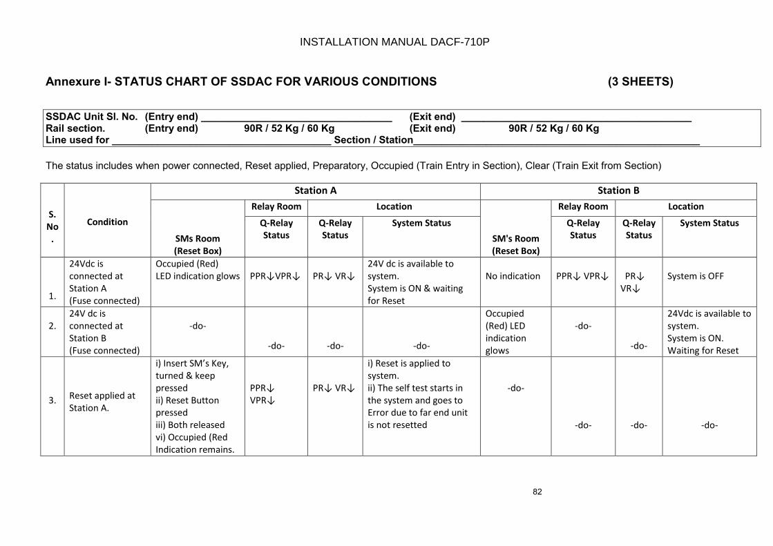
82
Annexure I- STATUS CHART OF SSDAC FOR VARIOUS CONDITIONS (3 SHEETS)
SSDAC Unit Sl. No. (Entry end) __________________________________ (Exit end) _________________________________________ Rail section. (Entry end) 90R / 52 Kg / 60 Kg (Exit end) 90R / 52 Kg / 60 Kg Line used for _______________________________________ Section / Station___________________________________________________
The status includes when power connected, Reset applied, Preparatory, Occupied (Train Entry in Section), Clear (Train Exit from Section)
S.
No
.
Condition
Station A Station B
SMs Room
(Reset Box)
Relay Room Location
SM's Room
(Reset Box)
Relay Room Location
Q-Relay
Status
Q-Relay
Status
System Status Q-Relay
Status
Q-Relay
Status
System Status
1.
24Vdc is
connected at
Station A
(Fuse connected)
Occupied (Red)
LED indication glows PPR↓VPR↓ PR↓ VR↓
24V dc is available to
system.
System is ON & waiting
for Reset
No indication PPR↓ VPR↓ PR↓
VR↓
System is OFF
2.
24V dc is
connected at
Station B
(Fuse connected)
-do-
-do- -do- -do-
Occupied
(Red) LED
indication
glows
-do-
-do-
24Vdc is available to
system.
System is ON.
Waiting for Reset
3. Reset applied at
Station A.
i) Insert SM’s Key,
turned & keep
pressed
ii) Reset Button
pressed
iii) Both released
vi) Occupied (Red
Indication remains.
PPR↓
VPR↓
PR↓ VR↓
i) Reset is applied to
system.
ii) The self test starts in
the system and goes to
Error due to far end unit
is not resetted
-do-
-do- -do- -do-
INSTALLATION MANUAL DACF-710P
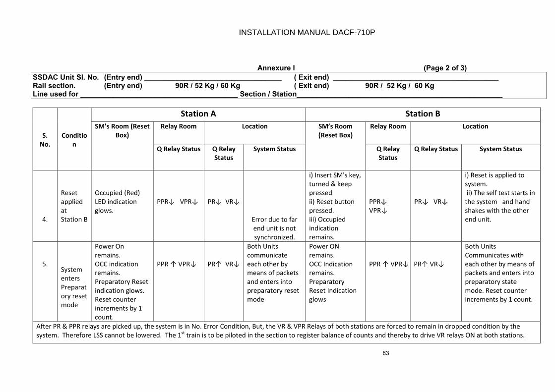
83
Annexure I (Page 2 of 3)
SSDAC Unit Sl. No. (Entry end) __________________________________ ( Exit end) _________________________________________ Rail section. (Entry end) 90R / 52 Kg / 60 Kg ( Exit end) 90R / 52 Kg / 60 Kg Line used for _______________________________________ Section / Station___________________________________________________
S.
No.
Conditio
n
Station A Station B
SM’s Room (Reset
Box)
Relay Room Location SM’s Room
(Reset Box)
Relay Room Location
Q Relay Status Q Relay
Status
System Status Q Relay
Status
Q Relay Status System Status
4.
Reset
applied
at
Station B
Occupied (Red)
LED indication
glows.
PPR↓ VPR↓ PR↓ VR↓
Error due to far
end unit is not
synchronized.
i) Insert SM's key,
turned & keep
pressed
ii) Reset button
pressed.
iii) Occupied
indication
remains.
PPR↓
VPR↓
PR↓ VR↓
i) Reset is applied to
system.
ii) The self test starts in
the system and hand
shakes with the other
end unit.
5. System
enters
Preparat
ory reset
mode
Power On
remains.
OCC indication
remains.
Preparatory Reset
indication glows.
Reset counter
increments by 1
count.
PPR ↑ VPR↓ PR↑ VR↓
Both Units
communicate
each other by
means of packets
and enters into
preparatory reset
mode
Power ON
remains.
OCC Indication
remains.
Preparatory
Reset Indication
glows
PPR ↑ VPR↓ PR↑ VR↓
Both Units
Communicates with
each other by means of
packets and enters into
preparatory state
mode. Reset counter
increments by 1 count.
After PR & PPR relays are picked up, the system is in No. Error Condition, But, the VR & VPR Relays of both stations are forced to remain in dropped condition by the
system. Therefore LSS cannot be lowered. The 1st
train is to be piloted in the section to register balance of counts and thereby to drive VR relays ON at both stations.
INSTALLATION MANUAL DACF-710P
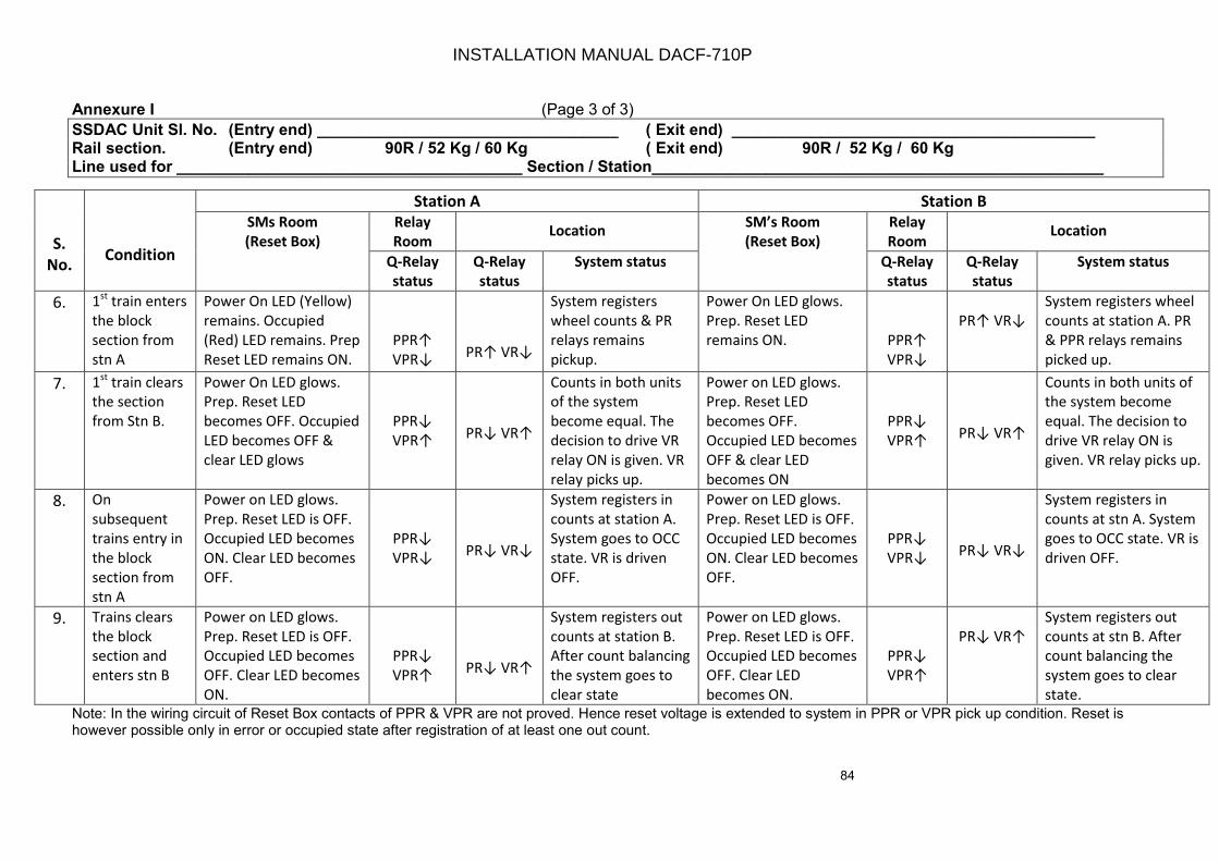
84
Annexure I (Page 3 of 3)
SSDAC Unit Sl. No. (Entry end) __________________________________ ( Exit end) _________________________________________ Rail section. (Entry end) 90R / 52 Kg / 60 Kg ( Exit end) 90R / 52 Kg / 60 Kg Line used for _______________________________________ Section / Station___________________________________________________
S.
No. Condition
Station A Station B
SMs Room
(Reset Box)
Relay
Room Location
SM’s Room
(Reset Box)
Relay
Room Location
Q-Relay
status
Q-Relay
status
System status Q-Relay
status
Q-Relay
status
System status
6. 1st
train enters
the block
section from
stn A
Power On LED (Yellow)
remains. Occupied
(Red) LED remains. Prep
Reset LED remains ON.
PPR↑
VPR↓ PR↑ VR↓
System registers
wheel counts & PR
relays remains
pickup.
Power On LED glows.
Prep. Reset LED
remains ON. PPR↑
VPR↓
PR↑ VR↓
System registers wheel
counts at station A. PR
& PPR relays remains
picked up.
7. 1st
train clears
the section
from Stn B.
Power On LED glows.
Prep. Reset LED
becomes OFF. Occupied
LED becomes OFF &
clear LED glows
PPR↓
VPR↑ PR↓ VR↑
Counts in both units
of the system
become equal. The
decision to drive VR
relay ON is given. VR
relay picks up.
Power on LED glows.
Prep. Reset LED
becomes OFF.
Occupied LED becomes
OFF & clear LED
becomes ON
PPR↓
VPR↑ PR↓ VR↑
Counts in both units of
the system become
equal. The decision to
drive VR relay ON is
given. VR relay picks up.
8. On
subsequent
trains entry in
the block
section from
stn A
Power on LED glows.
Prep. Reset LED is OFF.
Occupied LED becomes
ON. Clear LED becomes
OFF.
PPR↓
VPR↓ PR↓ VR↓
System registers in
counts at station A.
System goes to OCC
state. VR is driven
OFF.
Power on LED glows.
Prep. Reset LED is OFF.
Occupied LED becomes
ON. Clear LED becomes
OFF.
PPR↓
VPR↓ PR↓ VR↓
System registers in
counts at stn A. System
goes to OCC state. VR is
driven OFF.
9. Trains clears
the block
section and
enters stn B
Power on LED glows.
Prep. Reset LED is OFF.
Occupied LED becomes
OFF. Clear LED becomes
ON.
PPR↓
VPR↑ PR↓ VR↑
System registers out
counts at station B.
After count balancing
the system goes to
clear state
Power on LED glows.
Prep. Reset LED is OFF.
Occupied LED becomes
OFF. Clear LED
becomes ON.
PPR↓
VPR↑
PR↓ VR↑
System registers out
counts at stn B. After
count balancing the
system goes to clear
state.
Note: In the wiring circuit of Reset Box contacts of PPR & VPR are not proved. Hence reset voltage is extended to system in PPR or VPR pick up condition. Reset is however possible only in error or occupied state after registration of at least one out count.
INSTALLATION MANUAL DACF-710P
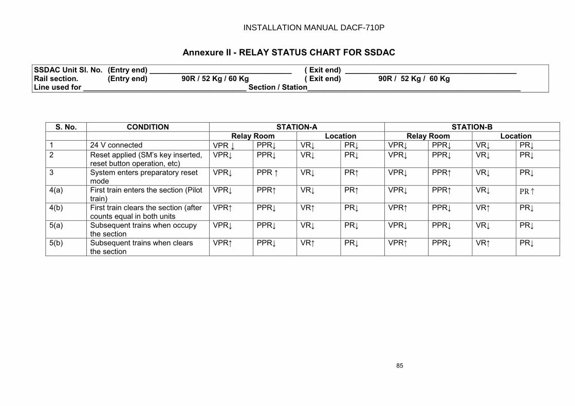
85
Annexure II - RELAY STATUS CHART FOR SSDAC
SSDAC Unit Sl. No. (Entry end) __________________________________ ( Exit end) _________________________________________ Rail section. (Entry end) 90R / 52 Kg / 60 Kg ( Exit end) 90R / 52 Kg / 60 Kg Line used for _______________________________________ Section / Station___________________________________________________
S. No. CONDITION STATION-A STATION-B
Relay Room Location Relay Room Location
1 24 V connected VPR ↓ PPR↓ VR↓ PR↓ VPR↓ PPR↓ VR↓ PR↓
2 Reset applied (SM’s key inserted, reset button operation, etc)
VPR↓ PPR↓ VR↓ PR↓ VPR↓ PPR↓ VR↓ PR↓
3 System enters preparatory reset mode
VPR↓ PPR ↑ VR↓ PR↑ VPR↓ PPR↑ VR↓ PR↓
4(a) First train enters the section (Pilot train)
VPR↓ PPR↑ VR↓ PR↑ VPR↓ PPR↑ VR↓
4(b) First train clears the section (after counts equal in both units
VPR↑ PPR↓ VR↑ PR↓ VPR↑ PPR↓ VR↑ PR↓
5(a) Subsequent trains when occupy the section
VPR↓ PPR↓ VR↓ PR↓ VPR↓ PPR↓ VR↓ PR↓
5(b) Subsequent trains when clears the section
VPR↑ PPR↓ VR↑ PR↓ VPR↑ PPR↓ VR↑ PR↓
INSTALLATION MANUAL DACF-710P
PR↑
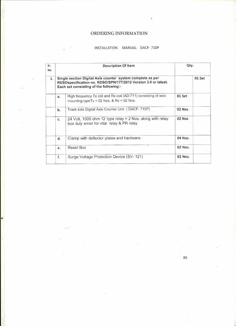
ORDERING INFORMATION

- 87 -
Annexure IV- FEEDBACK FORM
1. Purchase Order (P.O.) No. :
2. Consignee details :
3. Systems purchased directly from CEL : or through contractor
4. Sr. No. of the Systems :
5. Date of Receipt of System :
6. Date of Installation :
7. Type of Track Circuiting : For ex. Platform line, Block Working
8. Systems received in good condition : (any damage noticed during transit)
9. System has been installed by Railways or : Contractor
10. System Installation Manual received. : System has been installed as perinstructions given in the manual
11. Fault observed during system working :
12. The overall performance of the system :
13. Any suggestion for making improvement of : the system. Please specify
Dated:
Signature and Designation (Customer Railway)
INSTALLATION MANUAL DACF-710P

- 88 -
ANNEXURE V – DRAWINGS ( 38 SHEETS)
INSTALLATION MANUAL DACF-710P
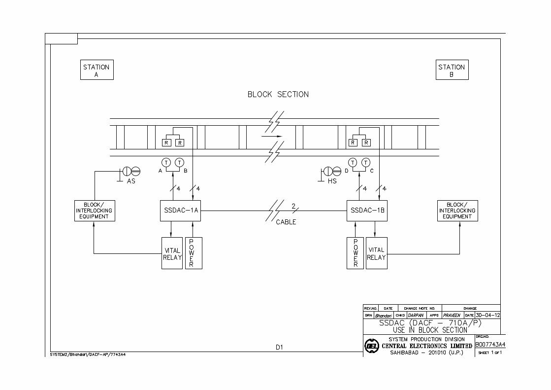
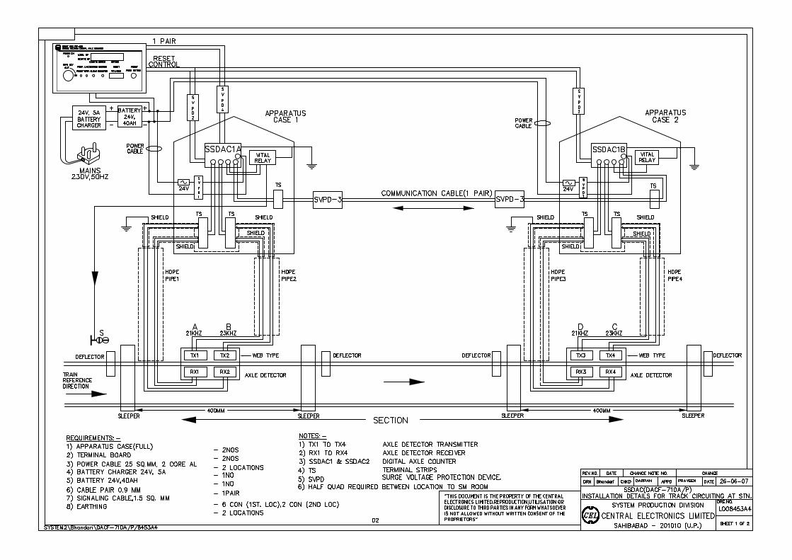

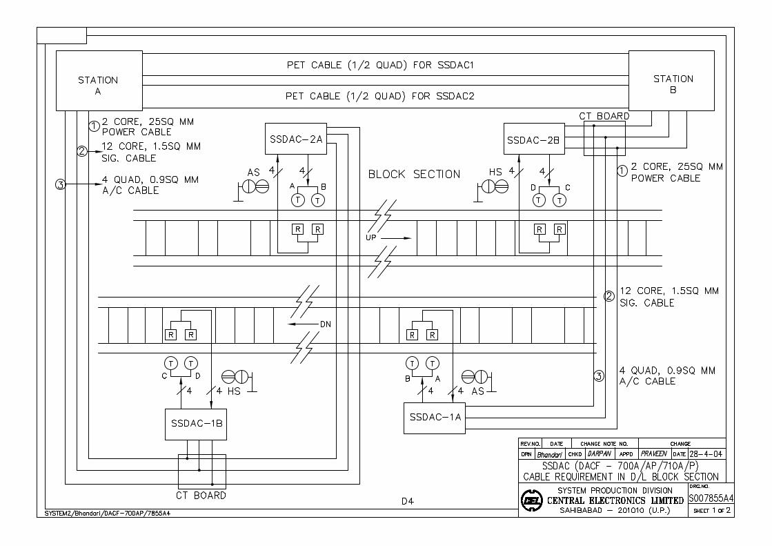
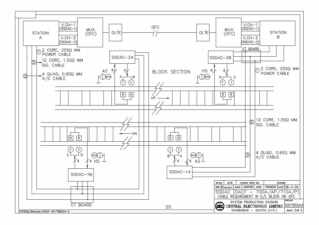
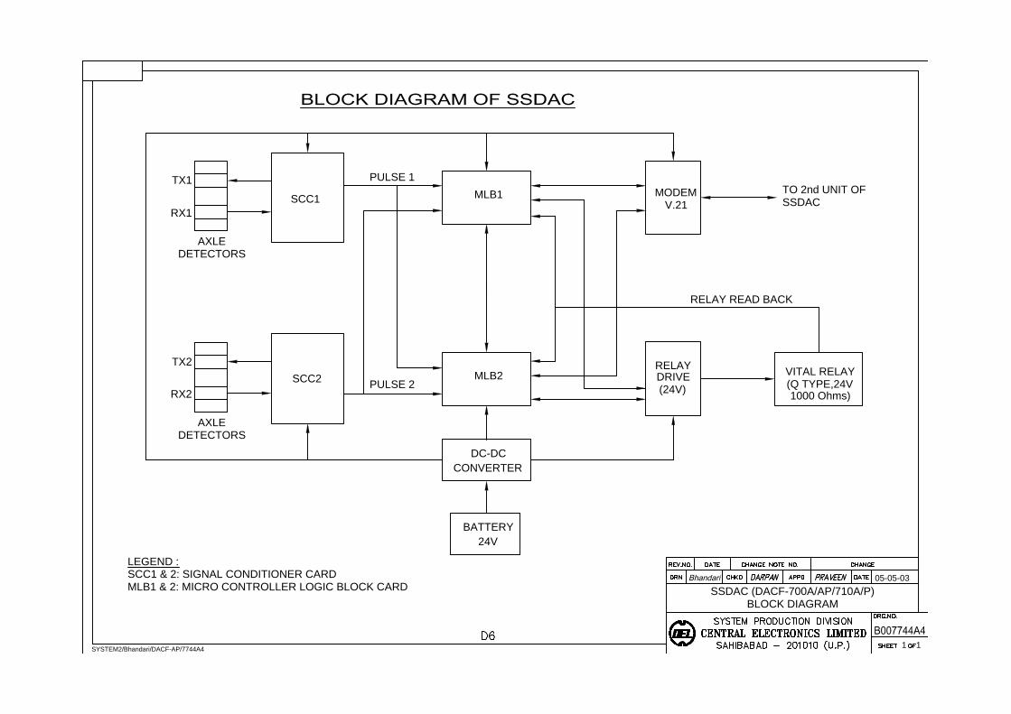
SCC1
TX1
RX1
AXLE
DETECTORS
MLB1
MODEM
V.21
DETECTORS
RX2
TX2
AXLE
SCC2
MLB2
DRIVE
(24V)
VITAL RELAY
(Q TYPE,24V
RELAY
CONVERTER
DC-DC
24V
BATTERY
TO 2nd UNIT OF
SSDAC
SSDAC (DACF-700A/AP/710A/P)
BLOCK DIAGRAM
05-05-03
1 1
SYSTEM2/Bhandari/DACF-AP/7744A4
LEGEND :
SCC1 & 2: SIGNAL CONDITIONER CARD
MLB1 & 2: MICRO CONTROLLER LOGIC BLOCK CARD
PULSE 1
PULSE 2
RELAY READ BACK
1000 Ohms)
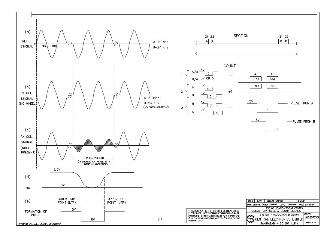
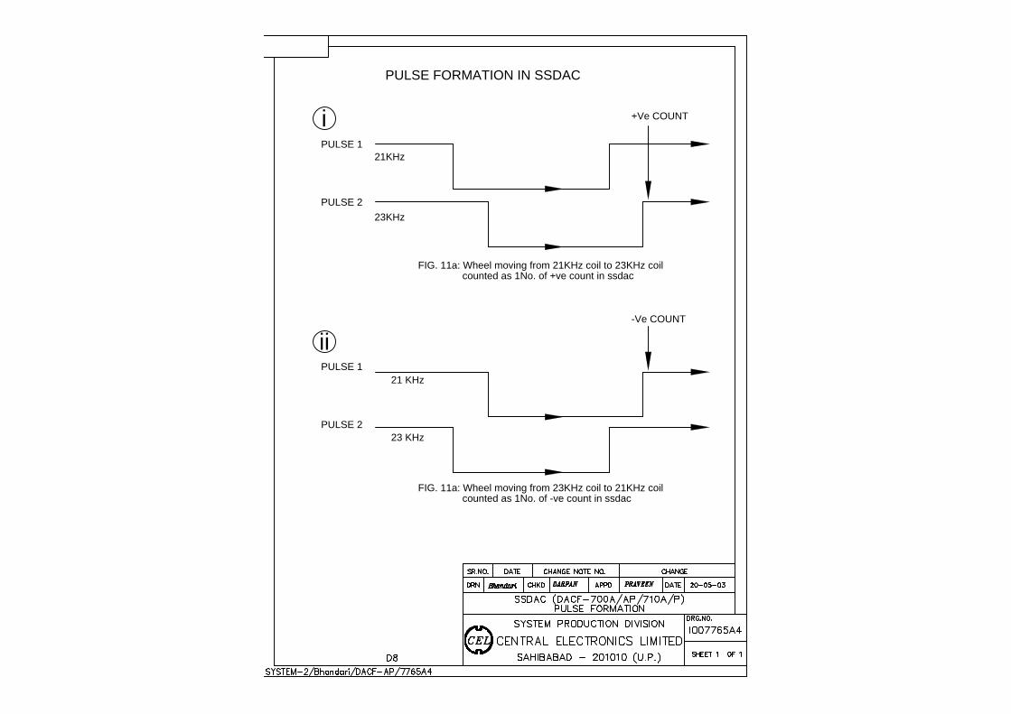
PULSE FORMATION IN SSDAC
PULSE 1
PULSE 2
FIG. 11a: Wheel moving from 21KHz coil to 23KHz coil
counted as 1No. of +ve count in ssdac
PULSE 2
PULSE 1
counted as 1No. of -ve count in ssdac
FIG. 11a: Wheel moving from 23KHz coil to 21KHz coil
+Ve COUNT
-Ve COUNT
21 KHz
21KHz
23KHz
i
ii
23 KHz
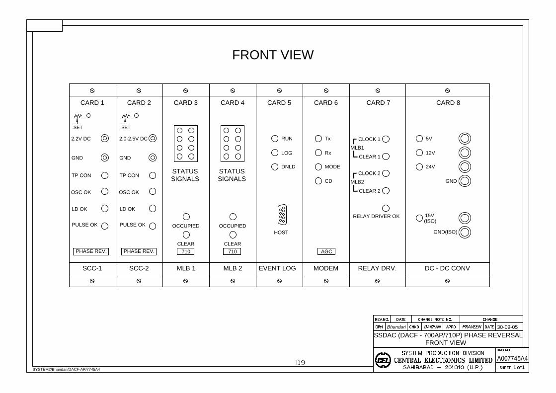
CARD 1 CARD 2 CARD 3 CARD 5 CARD 6
2.2V DC
GND
TP CON
OSC OK
LD OK
PULSE OK
SCC-1 SCC-2 MLB 1
STATUS
SIGNALS
OCCUPIED
CLEAR CLEAR
MLB 2
OCCUPIED
CARD 4
SIGNALS
STATUS
MODEM
Tx
Rx
MODE
CD
CARD 7
RELAY DRV.
CLOCK 1
CLEAR 1
MLB1
MLB2
CLEAR 2
CLOCK 2
RELAY DRIVER OK
CARD 8
DC - DC CONV
15V
24V
12V
5V
GND(ISO)
GND
30-09-05
SSDAC (DACF - 700AP/710P) PHASE REVERSAL
FRONT VIEW
1 1
SYSTEM2/Bhandari/DACF-AP/7745A4
FRONT VIEW
(ISO)
RUN
DNLD
LOG
EVENT LOG
SET
PHASE REV.
OSC OK
PHASE REV.
PULSE OK
LD OK
2.0-2.5V DC
TP CON
GND
SET
710 710
HOST
AGC
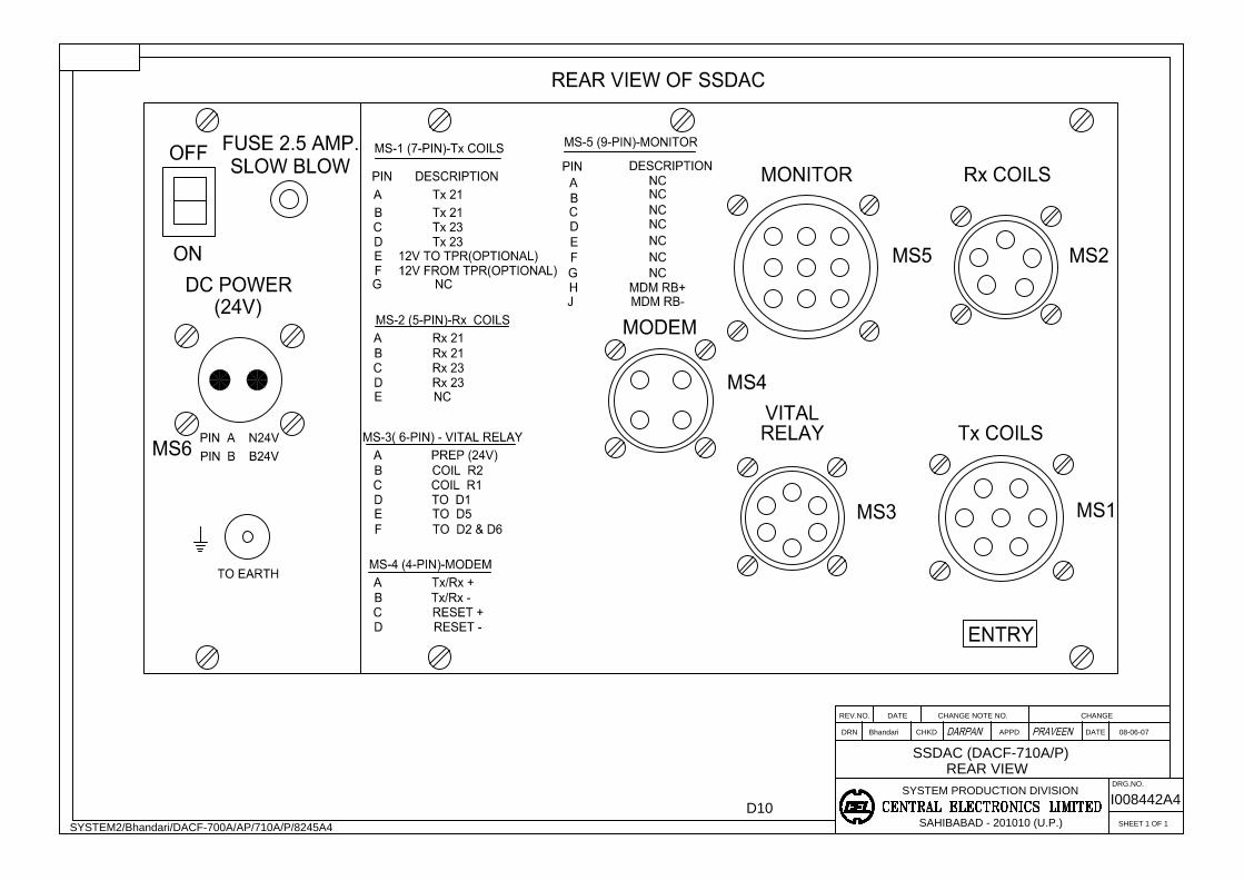
APPD
SAHIBABAD - 201010 (U.P.)
SYSTEM PRODUCTION DIVISION
CHKDDRN
REV.NO. DATE CHANGE NOTE NO.
SHEET 1 OF 1
CHANGE
DATE
DRG.NO.
Bhandari
REAR VIEW
SYSTEM2/Bhandari/DACF-700A/AP/710A/P/8245A4
08-06-07
I008442A4
SSDAC (DACF-710A/P)
D10
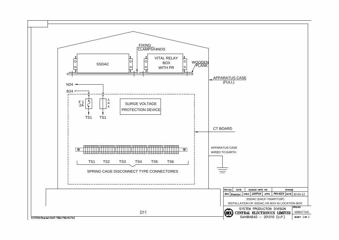
N24
B24
F 1
TS1 TS1
TS1
SPRING CAGE DISCONNECT TYPE CONNECTORES
SSDAC
VITAL RELAY
BOX
FIXING
WOODEN
30-04-12
1 1
I008477A3
SSDAC (DACF-700AP/710P)
INSTALLATION OF SSDAC,VR BOX IN LOCATION BOX
CLAMPSX4NOS
A
R
A
PLANK
APPARATUS CASE
(FULL)
2A
CT BOARD
APPARATUS CASE
WIRED TO EARTH
SURGE VOLTAGE
PROTECTION DEVICE
WITH PR
1 2 3 4 5 6 7 8 1 2 3 4 5 6 7 8 1 2 3 4 5 6 7 8 1 2 3 4 5 6 7 8 1 2 3 4 5 6 7 8 1 2 3 4 5 6 7 8
TS2 TS3 TS4 TS5 TS6
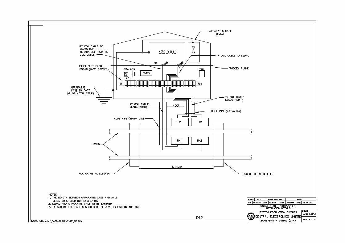
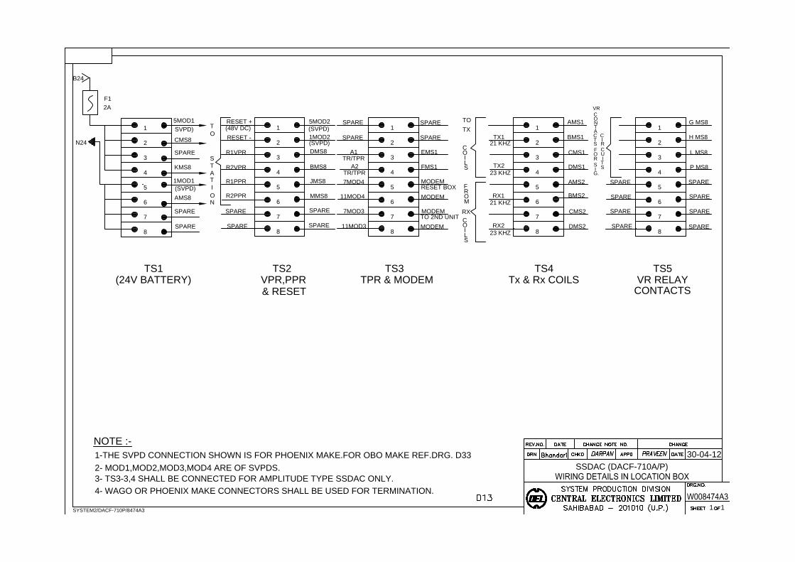
5MOD1
CMS8
SPARE
KMS8
AMS8
SPARE
SPARE
1
MMS8
JMS8
BMS8
DMS8
RESET +
RESET -
R1VPR
R2VPR
R1PPR
R2PPR
TS1 TS2 TS4 TS5
N24
B24
F1
30-04-12
SSDAC (DACF-710A/P)
1 1
SYSTEM2/DACF-710P/8474A3
NOTE :-
(24V BATTERY) VPR,PPR TPR & MODEM Tx & Rx COILS VR RELAY
2A
O
N
A
I
T
S
T
T
O
& RESET
CONTACTS
(48V DC)
SVPD)
1MOD1
(SVPD)
5MOD2
(SVPD)
1MOD2
(SVPD)
1-THE SVPD CONNECTION SHOWN IS FOR PHOENIX MAKE.FOR OBO MAKE REF.DRG. D33
2- MOD1,MOD2,MOD3,MOD4 ARE OF SVPDS.
SPARE
3- TS3-3,4 SHALL BE CONNECTED FOR AMPLITUDE TYPE SSDAC ONLY.
4- WAGO OR PHOENIX MAKE CONNECTORS SHALL BE USED FOR TERMINATION.
SPARE
SPARE
SPARE
2
3
4
5
6
7
8
1
2
3
4
5
6
7
8
MODEM
MODEM
FMS1
EMS1
SPARE
SPARE
A1
A2
7MOD4
11MOD4
SPARE
SPARE
7MOD3
11MOD3MODEM
MODEM
1
2
3
4
5
6
7
8
BMS2
AMS2
DMS1
CMS1
21 KHZ
AMS1
BMS1
DMS2
CMS2
1
2
3
4
5
6
7
8
P MS8
L MS8
G MS8
H MS8
SPARE
SPARESPARE
SPARE
1
2
3
4
5
6
7
8
TR/TPR
TR/TPR
RESET BOX
TO 2ND UNIT
SPARE
SPARE
SPARE
SPARE
VR
TO
TX
RX
TX1
23 KHZ
TX2
21 KHZ
RX1
23 KHZ
RX2
C
O
I
L
S
F
R
O
M
C
O
I
L
S
C
O
N
T
A
C
T
S
F
R
O
S
I
G.
C
I
R
C
U
I
T
S
TS3
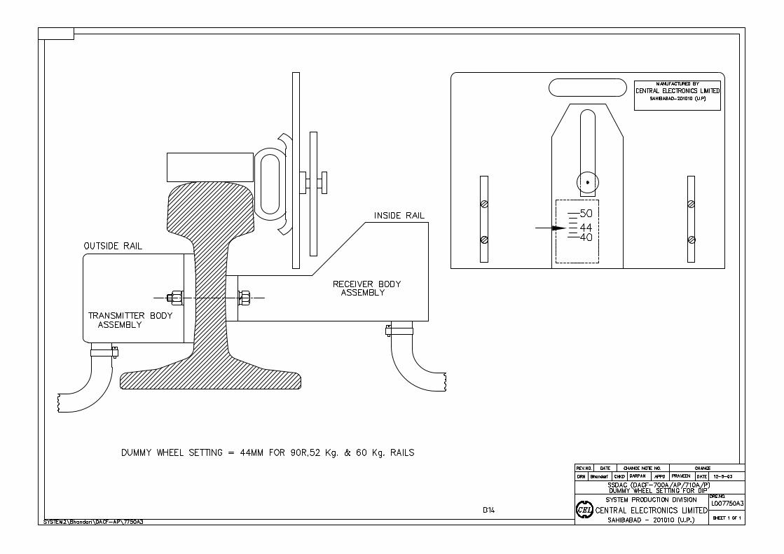
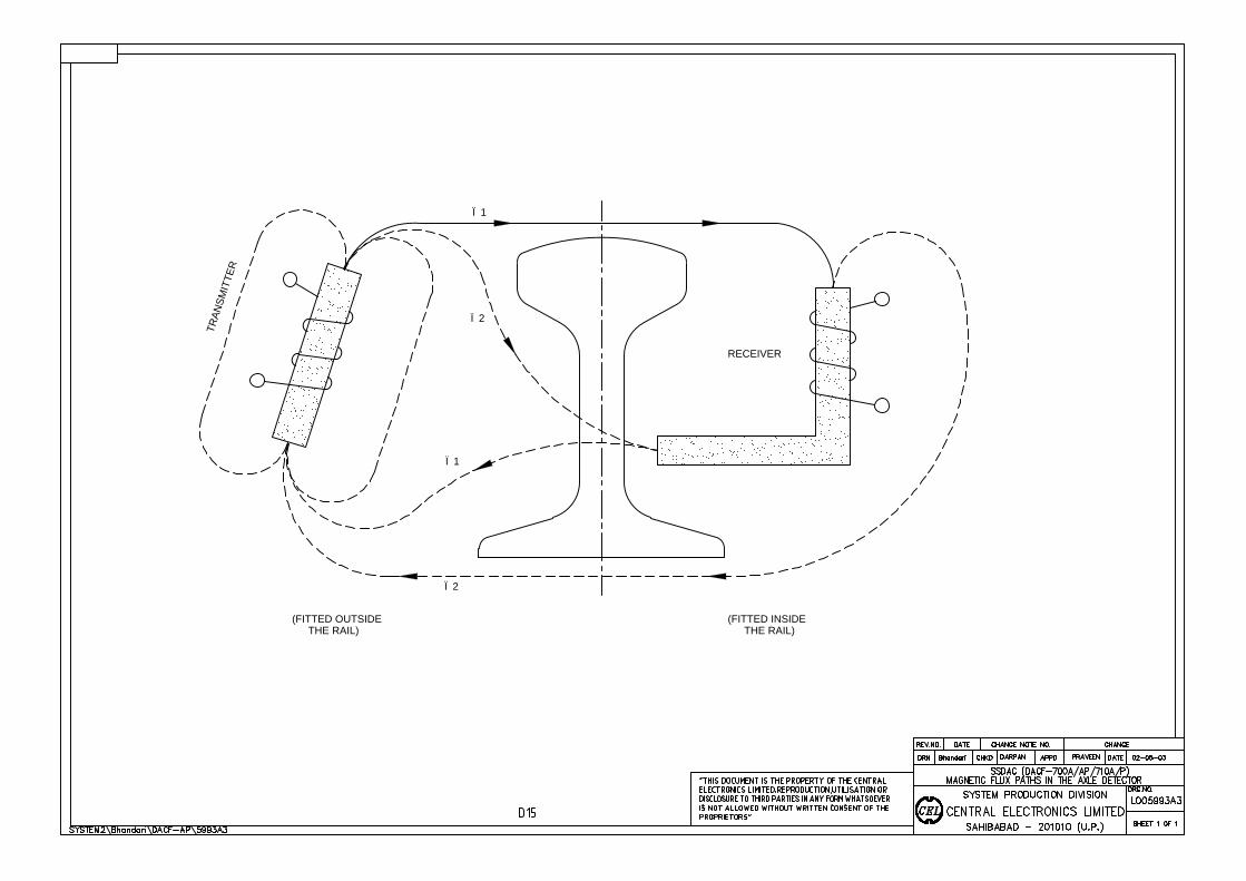
RECEIVER
T
R
A
N
S
M
I
T
T
E
R
Ï2
Ï2
Ï1
Ï1
(FITTED INSIDE
THE RAIL)
(FITTED OUTSIDE
THE RAIL)
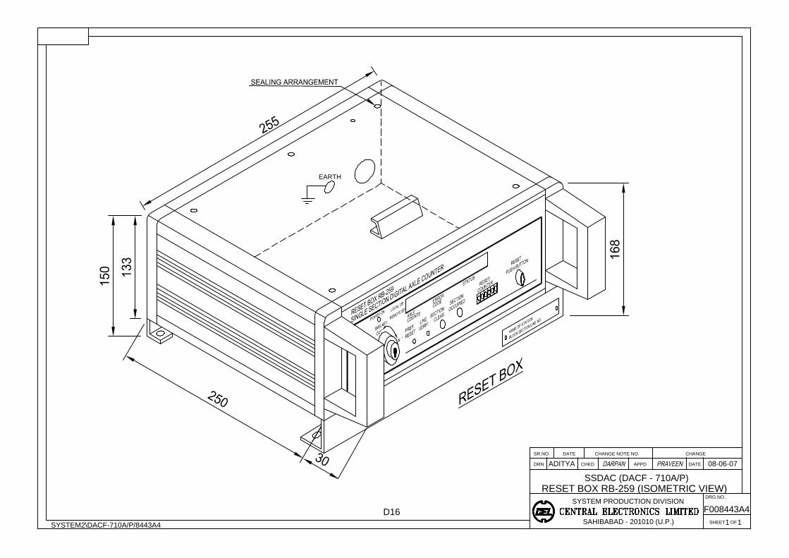
RESET BOX RB-259 (ISOMETRIC VIEW)
ADITYA 08-06-07
SYSTEM2\DACF-710A/P/8443A4
SSDAC (DACF - 710A/P)
CHANGE NOTE NO.
SYSTEM PRODUCTION DIVISION
SAHIBABAD - 201010 (U.P.)
DATESR.NO.
DRN CHKD
1 1
F008443A4
SHEET OF
APPD
DRG.NO.
CHANGE
DATE
D16
EARTH

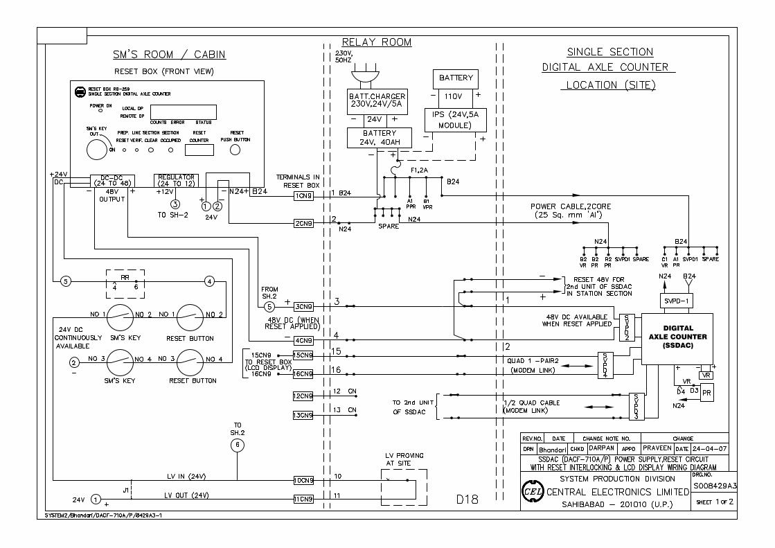
DIGITALAXLE COUNTER
(SSDAC)
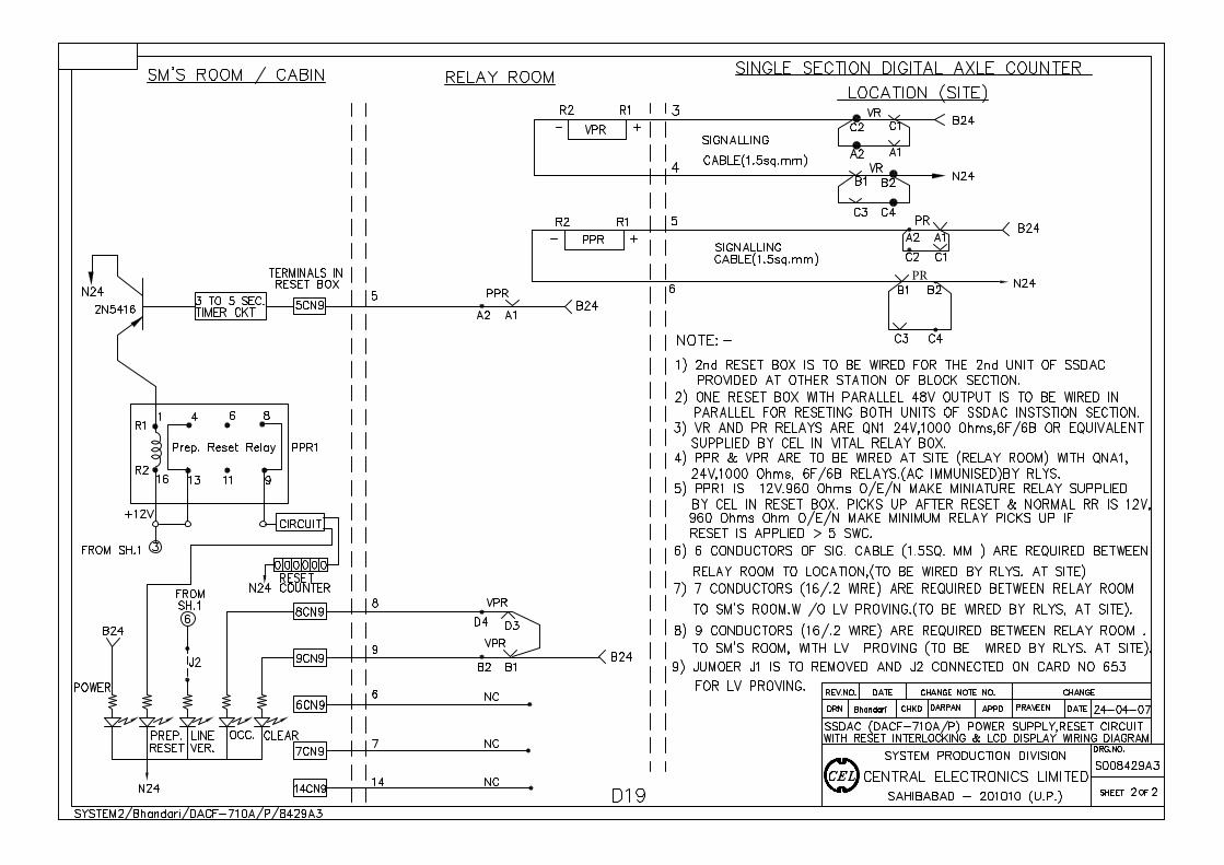
PR
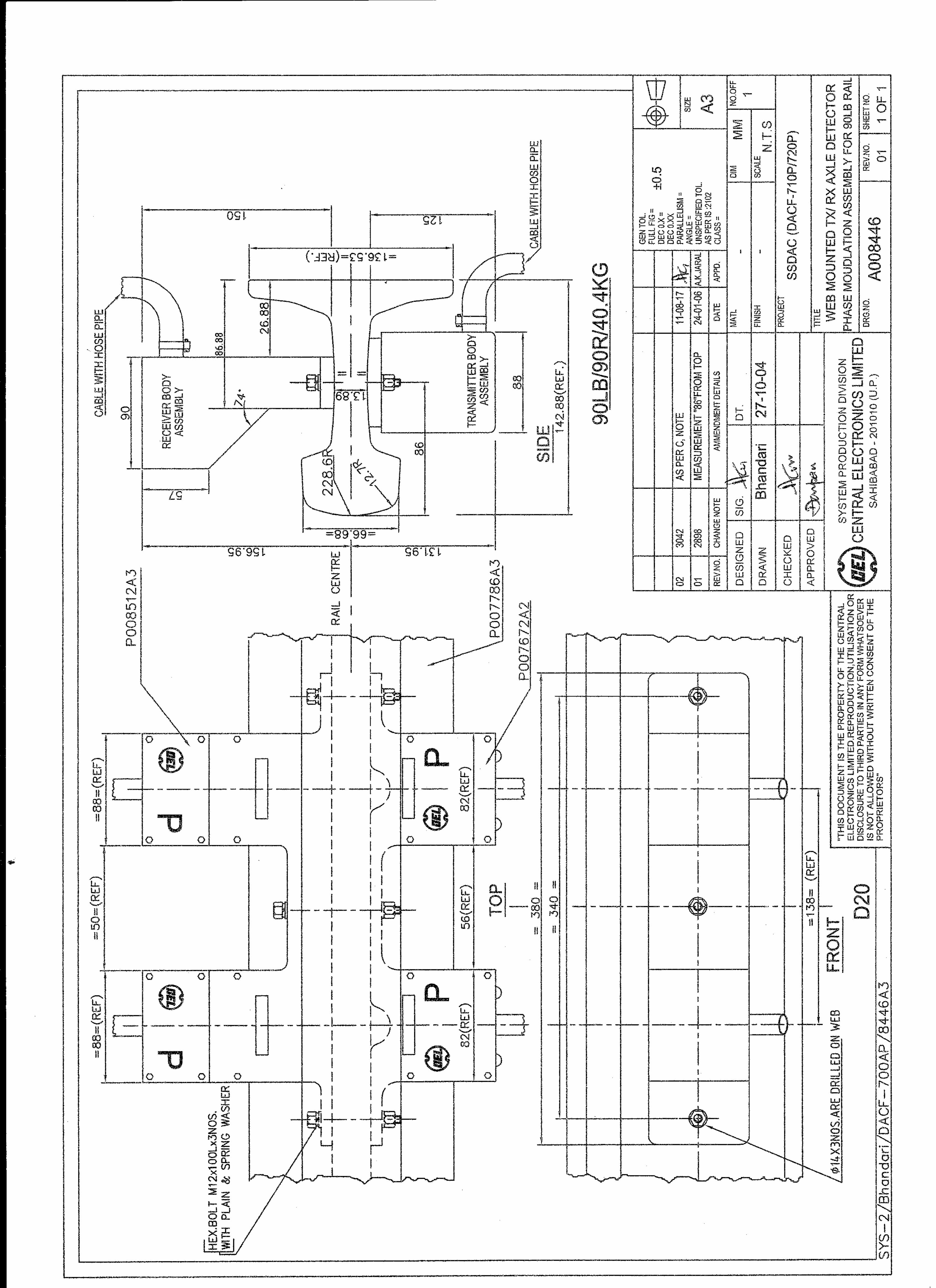
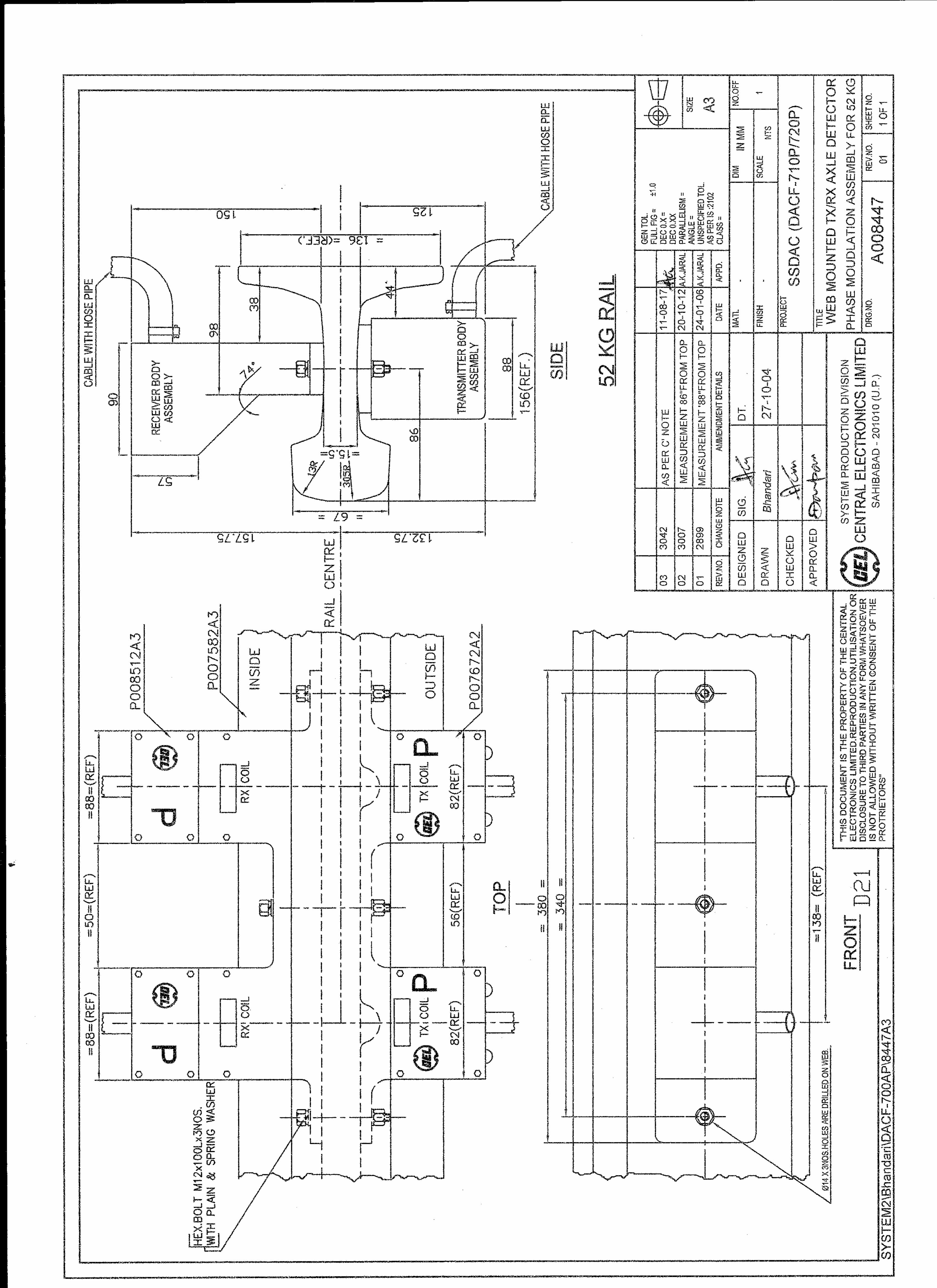
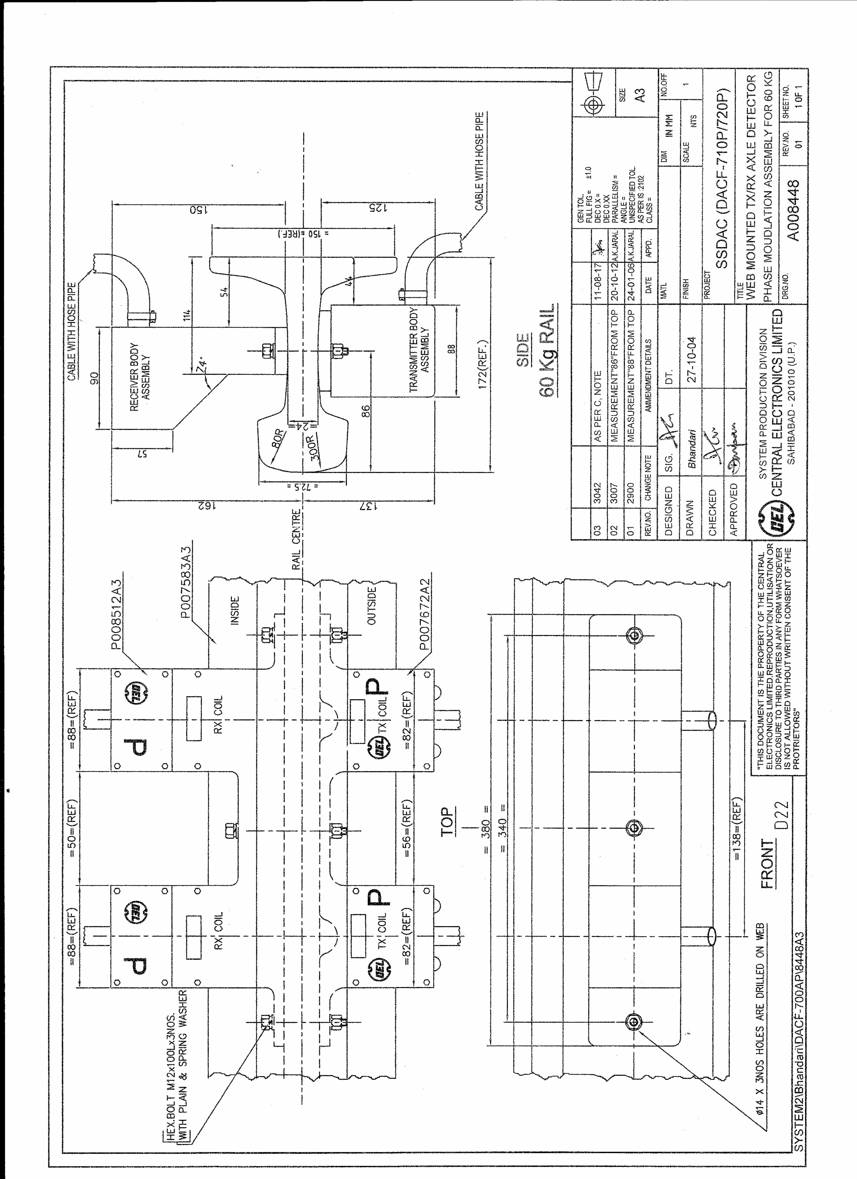
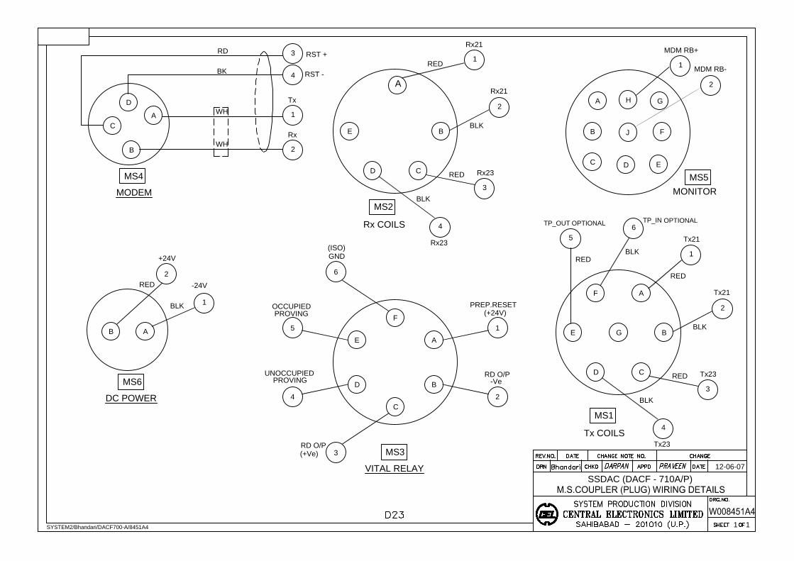
AF
E B
D C
G
5
6
1
2
3
4
RED
BLK
RED
BLK
RED
BLK
Tx21
Tx21
Tx23
Tx23
Rx23
Rx21
RED
E
1
BLK
D
4
BLK
C
RED
B
3
Rx23
Rx21
2
A
F
E A
D
C
B
6
5
4
3
PROVING
OCCUPIED
RD O/P
GND
VITAL RELAY
B A
+24V
2
RED
-24V
BLK
DC POWER
12-06-07
1 1
SSDAC (DACF - 710A/P)
SYSTEM2/Bhandari/DACF700-A/8451A4
MS1
Tx COILS
MS2
Rx COILS
MS6
MS3
(ISO)
UNOCCUPIED
PROVING
1
2
(+Ve)
-Ve
RD O/P
PREP.RESET
(+24V)
MODEM
Rx
C
MS4
A
D
B
2
1
Tx
1
WH
WH
RST +
RD
BK
RST -
4
3
TP_OUT
TP_IN
C
B
J
D
A
H
F
E
G
MDM RB-
MDM RB+
1
2
MONITOR
MS5
OPTIONAL
OPTIONAL
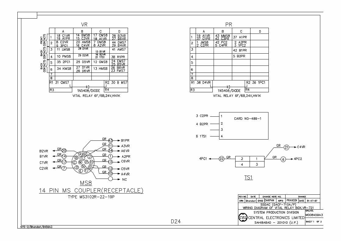
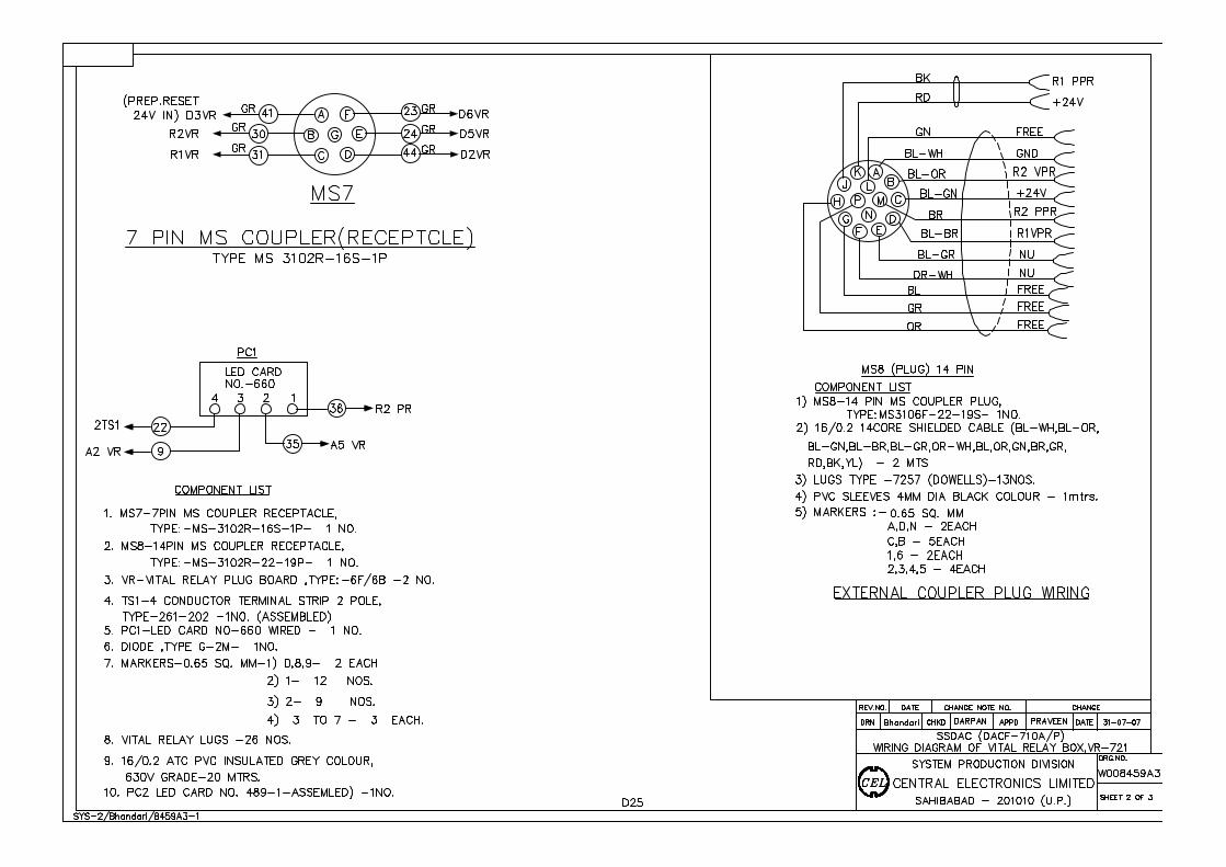
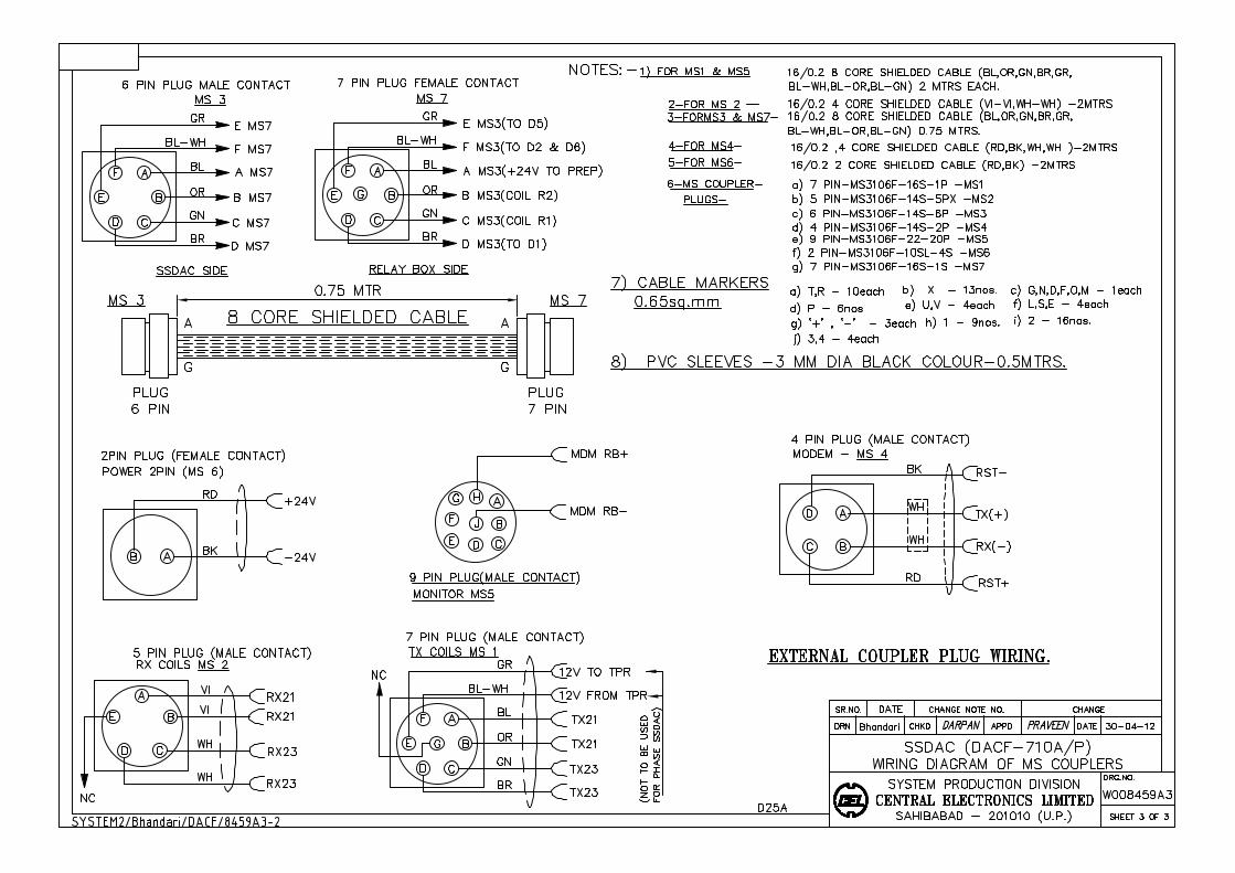
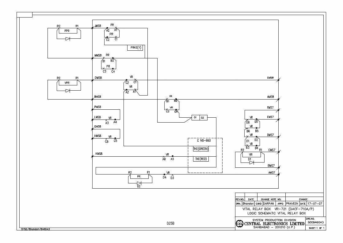
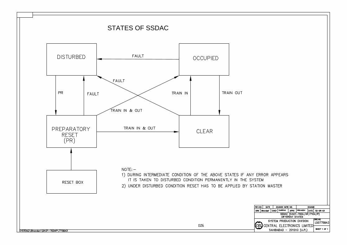
STATES OF SSDAC
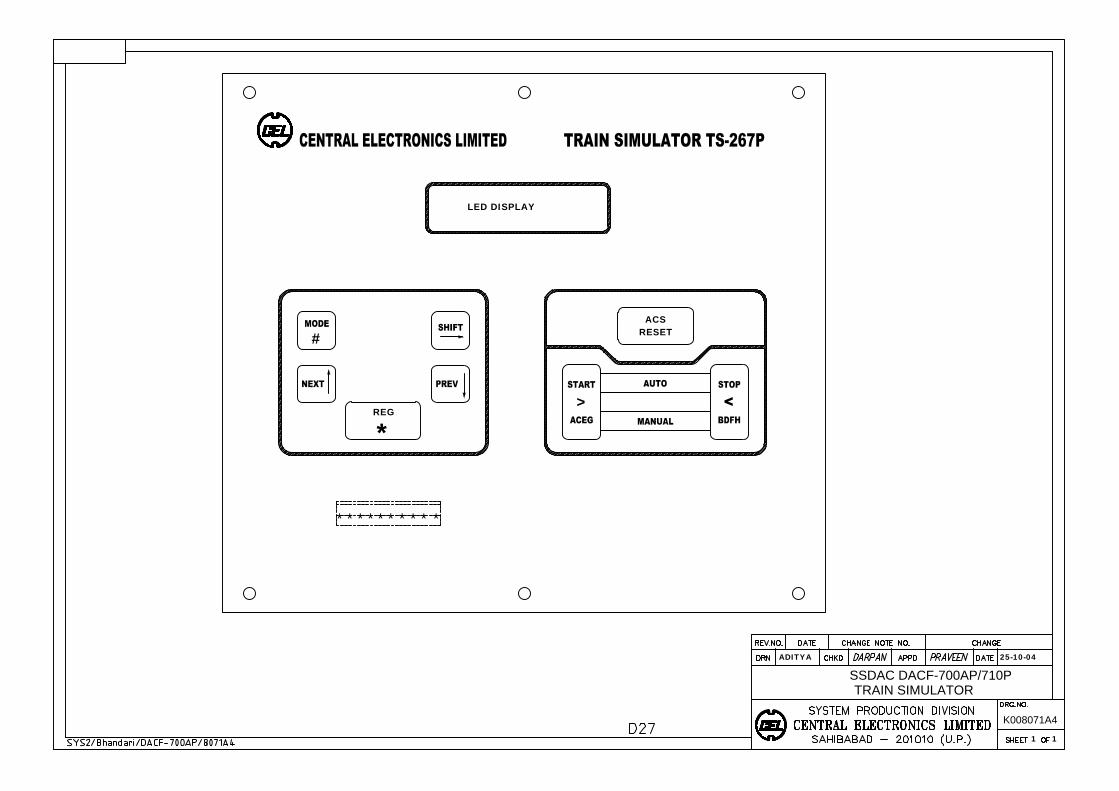
#
REG
*
ACSRESET
>
LED DISPLAY
* * * * * * * * * *
TRAIN SIMULATOR
ADITYA 25-10-04
K008071A4
1 1
SSDAC DACF-700AP/710P
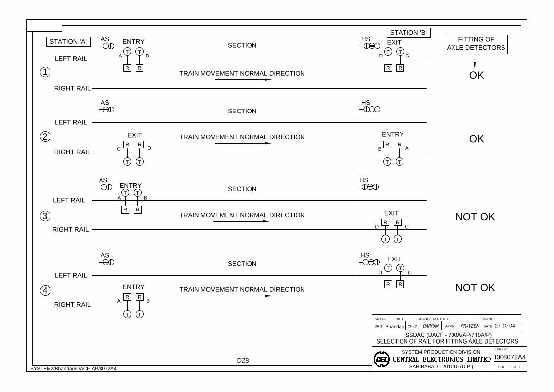
APPD
SAHIBABAD - 201010 (U.P.)
SYSTEM PRODUCTION DIVISION
CHKDDRN
SR.NO. DATE CHANGE NOTE NO.
SHEET 1 OF 1
CHANGE
DATE
DRG.NO.
Bhandari
SYSTEM2/Bhandari/DACF-AP/8072A4
27-10-04
AS
RIGHT RAIL
I008072A4
LEFT RAIL
HS
TRAIN MOVEMENT NORMAL DIRECTION
T
R
ENTRY
EXIT
1
AXLE DETECTORS
OK
RIGHT RAIL
LEFT RAIL
AS
ENTRY
EXIT
HS
OK
STATION 'B'
STATION 'A'
RIGHT RAIL
LEFT RAIL
AS
ENTRY
EXIT
NOT OK
RIGHT RAIL
LEFT RAIL
AS
ENTRY
EXIT
NOT OK
2
3
4
A B
A B
D C
D C
D C
A
B
D
C
A B
FITTING OF
SECTION
SECTION
TRAIN MOVEMENT NORMAL DIRECTION
TRAIN MOVEMENT NORMAL DIRECTION
SECTION
TRAIN MOVEMENT NORMAL DIRECTION
SECTION
HS
HS
T
R
TT
R R
R R
T TT T
RR
TT
R R
RR
TT
T T
R R
RR
TT
D28
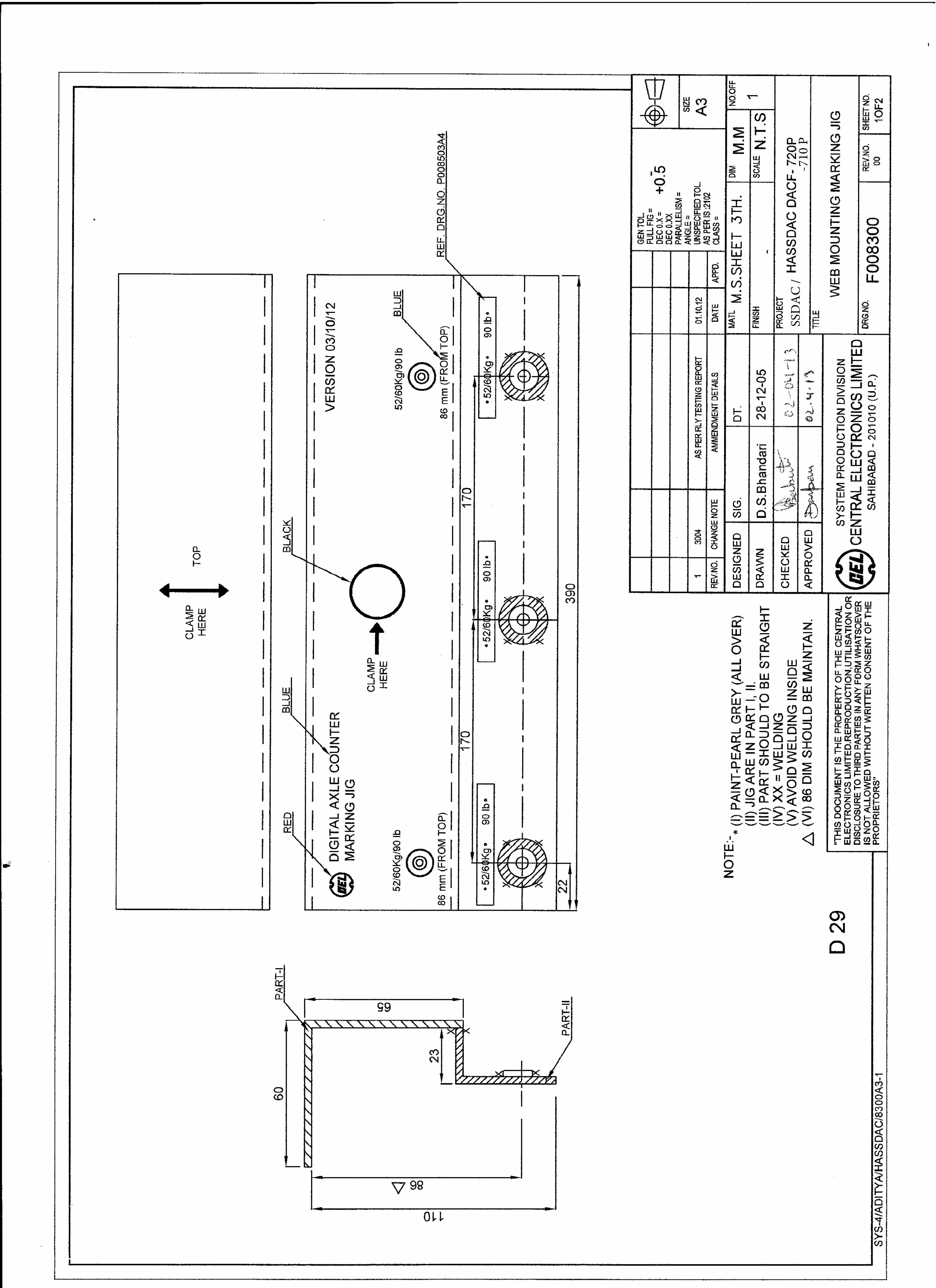
SSD
AC
/-7
10 P
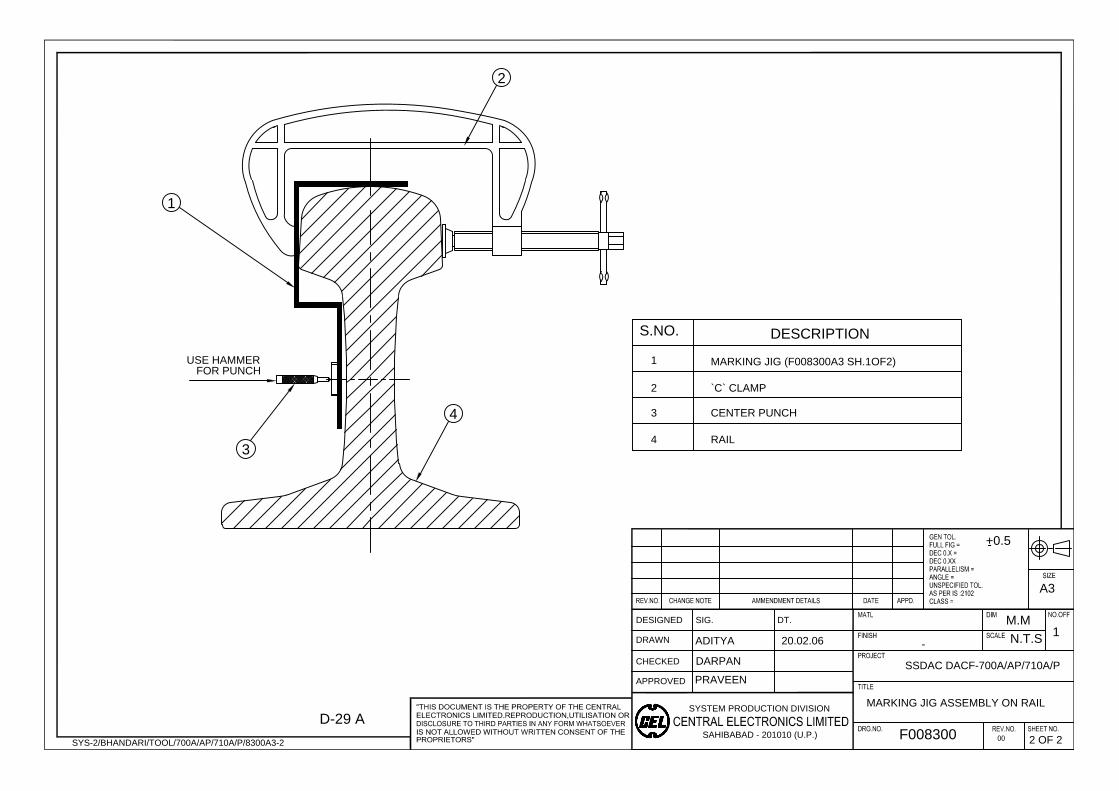
SYSTEM PRODUCTION DIVISION
SAHIBABAD - 201010 (U.P.)
DESIGNED
DRAWN
CHECKED
APPROVED
SIG. DT.
M.M
N.T.S
1
ADITYA
SSDAC DACF-700A/AP/710A/P
A3
+0.5
-
MARKING JIG ASSEMBLY ON RAIL
-
F008300
SYS-2/BHANDARI/TOOL/700A/AP/710A/P/8300A3-2
20.02.06
2 OF 2
FOR PUNCH
3
1
2
S.NO.
DESCRIPTION
1
2
3
MARKING JIG (F008300A3 SH.1OF2)
`C` CLAMP
CENTER PUNCH
D-29 A
4
4 RAIL
USE HAMMER
DARPAN
PRAVEEN
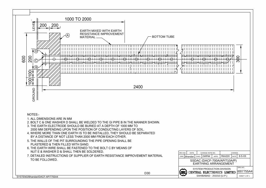
APPD
SAHIBABAD - 201010 (U.P.)
SYSTEM PRODUCTION DIVISION
CHKDDRN
REV.NO. DATE CHANGE NOTE NO.
SHEET 1 OF 1
CHANGE
DATE
DRG.NO.
Bhandari
SYSTEM2/Bhandari/DACF-AP/7755A4
8-5-03
EARTH MIXED WITH EARTH
EARTHING ARRANGEMENT
I007755A4
LE
VE
LG
RO
UN
D
A
D
C
B
BOTTOM TUBE
SSDAC (DACF-700A/AP/710A/P)
D30
RESISTANCE IMPROVEMENT
MATERIAL
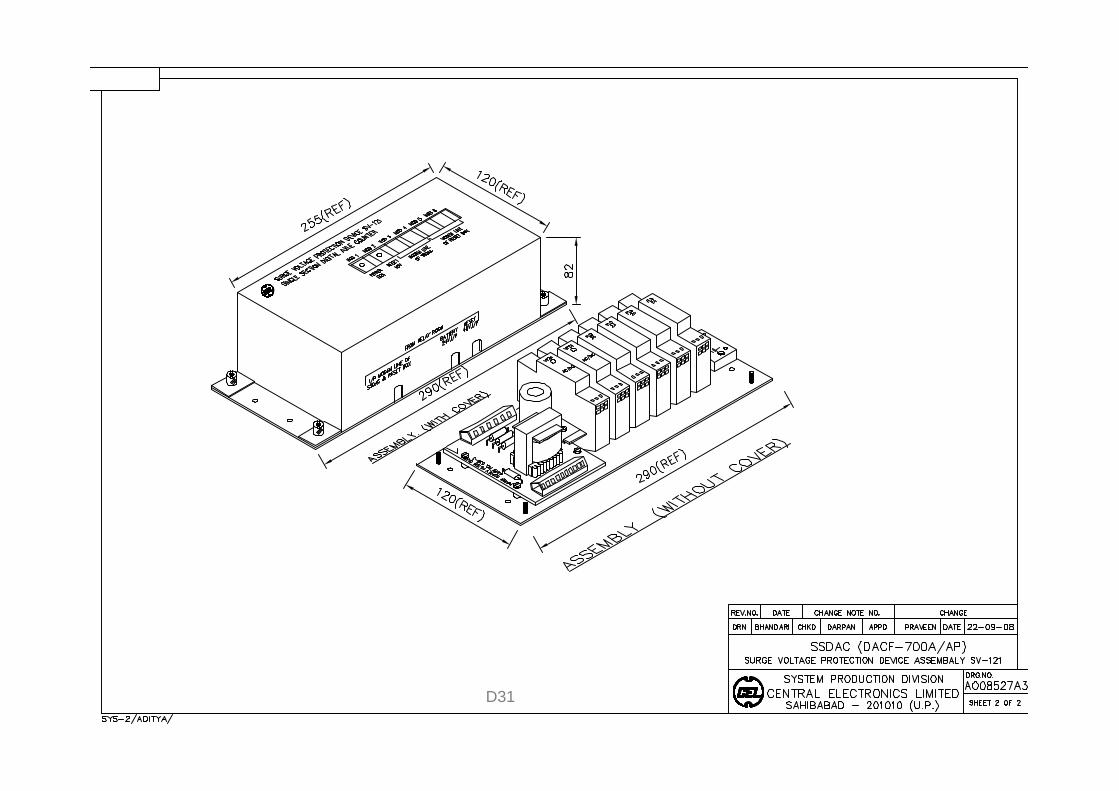
D31
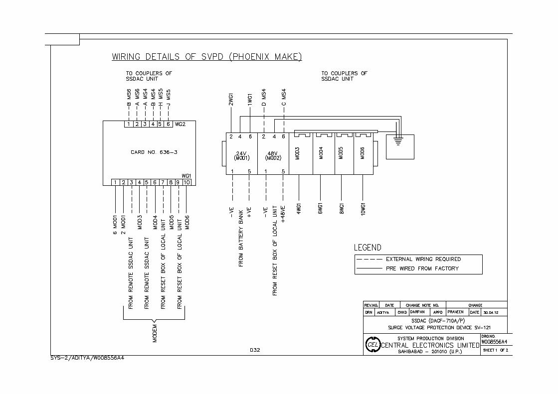
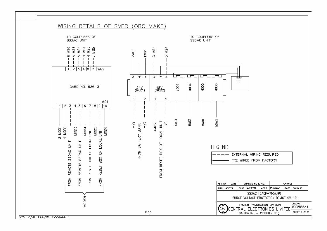
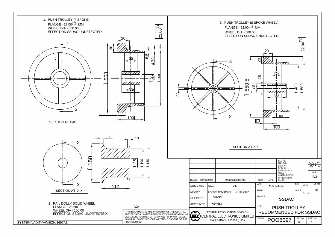
SYSTEM PRODUCTION DIVISION
SAHIBABAD - 201010 (U.P.)
DESIGNED
DRAWN
CHECKED
APPROVED
SIG. DT.
SYSTEM4/ADITYA/MECH/8697A3
A3
7
6.5
10
10
Ï100
Ï130
PUSH TROLLEY
X
X
X
X
SECTION AT X-X
4.7
3
22
.0
0
20
Ï25
=65=
=80=
Ï25
112
100
30
POO8697
0 1
M.M.
N.T.S.
01
1. PUSH TROLLEY (4 SPOKE)
FLANGE - 22.00 MM
WHEEL DIA - 500.00
2. RAIL DOLLY SOLID WHEEL
FLANGE - 25mm
WHEEL DIA - 100.00
Ï150
Ï558
Ï28
7.5
X
X
28
20
100
80
65
3. PUSH TROLLEY (8 SPOKE WHEEL)
WHEEL DIA - 500.00
Ï550.5
88
Ï483
Ï500
Ï73
10
M.S. ALLOY.
SSDAC
SHASHI BHUSHAN
21.04.2012
8
SECTION AT X-X
SECTION AT X-X
+
-
2
22
.0
0
+
-
2
Ï500
+
-
2
FLANGE - 22.00 MM
+
-
2
EFFECT ON SSDAC-UNDETECTED
EFFECT ON SSDAC-UNDETECTED
EFFECT ON SSDAC-UNDETECTED
RECOMMENDED FOR SSDAC
D34

- 89 -
ANNEXURE – VI – PRECOMMISSIONING CHECKLIST
INSTALLATION MANUAL DACF-710P