Embed Size (px)
Citation preview
DA-927A DA-928A
Please read this manual before using the machine. Please keep this manual within easy reach for quick reference.
TWIN NEEDLE / THREE NEEDLE FEED OFF THE ARM DOUBLE
CHAIN STITCHER
INSTRUCTIONMANUAL
DA-927A, DA-928A i
Thank you very much for buying a BROTHER sewing machine. Before using your new machine, please read the safety instructions and the explanations given in the instruction manual. With industrial sewing machines, it is normal to carry out work while positioned directly in front of moving parts such as the needle and thread take-up, and consequently there is always a danger of injury that can be caused by these parts. Follow the instructions from training personnel and instructors regarding safe and correct operation before operating the machine so that you will know how to use it correctly.
SAFETY INSTRUCTIONS
[1] Safety indications and their meanings This instruction manual and the indications and symbols that are used on the machine itself are provided in order to ensure safe operation of this machine and to prevent accidents and injury to yourself or other people. The meanings of these indications and symbols are given below.
Indications
CAUTION The instructions which follow this term indicate situations where failure to follow the instructions may result in minor or moderate injury.
Symbols
· · · · · This symbol (△) indicates something that you should be careful of. The picture inside the triangle indicates the nature of the caution that must be taken. (For example, the symbol at left means “beware of injury”.)
· · · · · This symbol ( ) indicates something that you must not do.
· · · · · This symbol (●) indicates something that you must do. The picture inside the circle indicates the
nature of the thing that must be done. (For example, the symbol at left means “you must make the ground connection”.)
DA-927A, DA-928A ii
[2] Notes on safety
CAUTION Environmental requirements
Use the sewing machine in an area which is free from sources of strong electrical noise such as electrical line noise or static electric noise. Sources of strong electrical noise may cause problems with correct operation.
Any fluctuations in the power supply voltage should be within 10% of the rated voltage for the machine. Voltage fluctuations which are greater than this may cause problems with correct operation.
The power supply capacity should be greater than the requirements for the sewing machine's power consumption. Insufficient power supply capacity may cause problems with correct operation.
The ambient temperature should be within the range of 5C to 35C during use. Temperatures which are lower or higher than this may cause problems with correct operation.
The relative humidity should be within the range of 45% to 85% during use, and no dew formation should occur in any devices. Excessively dry or humid environments and dew formation may cause problems with correct operation.
In the event of an electrical storm, turn off the power and disconnect the power cord from the wall outlet. Lightning may cause problems with correct operation.
Installation
Machine installation should only be carried out by a qualified technician.
Contact your Brother dealer or a qualified electrician for any electrical work that may need to be done.
The sewing machine weighs approximately 49 kg (108lb). The installation should be carried out by two or more people.
Do not connect the power cord until installation is complete. The machine may operate if the treadle is depressed by mistake, which could result in injury.
Be sure to connect the ground. If the ground connection is not secure, you run a high risk of receiving a serious electric shock, and problems with correct operation may also occur.
All cords should be secured at least 25 mm away from any moving parts. Furthermore, do not excessively bend the cords or secure them too firmly with staples. If this is not observed, fire or electric shocks may result.
If using a work table which has casters, the casters should be secured in such a way so that they cannot move.
Be sure to wear protective goggles and gloves when handling the lubricating oil, so that it does not get into your eyes or onto your skin. If care is not taken, inflammation can result. Furthermore, do not drink the lubricating oil. Diarrhea or vomiting may result. Keep the oil out of the reach of children.
DA-927A, DA-928A iii
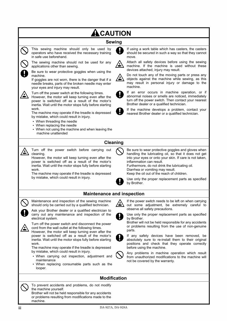
CAUTION Sewing
This sewing machine should only be used by operators who have received the necessary training in safe use beforehand.
The sewing machine should not be used for any applications other than sewing.
Be sure to wear protective goggles when using the machine. If goggles are not worn, there is the danger that if a needle breaks, parts of the broken needle may enter your eyes and injury may result.
Turn off the power switch at the following times. However, the motor will keep turning even after the power is switched off as a result of the motor’s inertia. Wait until the motor stops fully before starting work. The machine may operate if the treadle is depressed by mistake, which could result in injury. When threading the needle When replacing the needle When not using the machine and when leaving the
machine unattended
If using a work table which has casters, the casters should be secured in such a way so that they cannot move.
Attach all safety devices before using the sewing machine. If the machine is used without these devices attached, injury may result.
Do not touch any of the moving parts or press any objects against the machine while sewing, as this may result in personal injury or damage to the machine.
If an error occurs in machine operation, or if abnormal noises or smells are noticed, immediately turn off the power switch. Then contact your nearest Brother dealer or a qualified technician.
If the machine develops a problem, contact your nearest Brother dealer or a qualified technician.
Cleaning
Turn off the power switch before carrying out cleaning. However, the motor will keep turning even after the power is switched off as a result of the motor’s inertia. Wait until the motor stops fully before starting work. The machine may operate if the treadle is depressed by mistake, which could result in injury.
Be sure to wear protective goggles and gloves when handling the lubricating oil, so that it does not get into your eyes or onto your skin. If care is not taken, inflammation can result. Furthermore, do not drink the lubricating oil. Diarrhea or vomiting may result. Keep the oil out of the reach of children.
Use only the proper replacement parts as specified by Brother.
Maintenance and inspection
Maintenance and inspection of the sewing machine should only be carried out by a qualified technician.
Ask your Brother dealer or a qualified electrician to carry out any maintenance and inspection of the electrical system.
Turn off the power switch and disconnect the power cord from the wall outlet at the following times. However, the motor will keep turning even after the power is switched off as a result of the motor’s inertia. Wait until the motor stops fully before starting work. The machine may operate if the treadle is depressed by mistake, which could result in injury. When carrying out inspection, adjustment and
maintenance When replacing consumable parts such as the
looper.
If the power switch needs to be left on when carrying out some adjustment, be extremely careful to observe all safety precautions.
Use only the proper replacement parts as specified by Brother. Brother will not be held responsible for any accidents or problems resulting from the use of non-genuine parts.
If any safety devices have been removed, be absolutely sure to re-install them to their original positions and check that they operate correctly before using the machine.
Any problems in machine operation which result from unauthorized modifications to the machine will not be covered by the warranty.
Modification
To prevent accidents and problems, do not modify the machine yourself. Brother will not be held responsible for any accidents or problems resulting from modifications made to the machine.
DA-927A, DA-928A iv
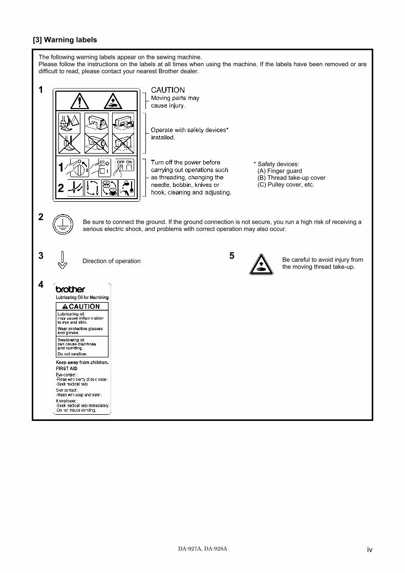
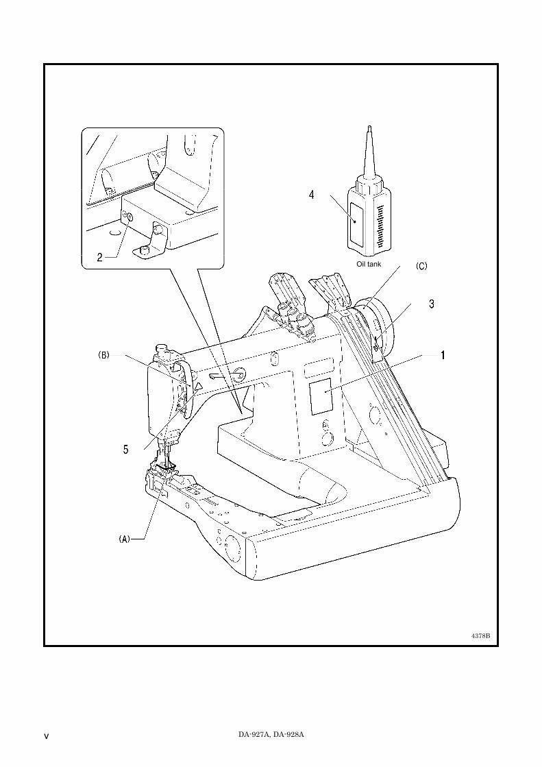
[3] Warning labels
The following warning labels appear on the sewing machine. Please follow the instructions on the labels at all times when using the machine. If the labels have been removed or are difficult to read, please contact your nearest Brother dealer.
1
2 Be sure to connect the ground. If the ground connection is not secure, you run a high risk of receiving a serious electric shock, and problems with correct operation may also occur.
3 Direction of operation
5 Be careful to avoid injury from the moving thread take-up.
4
* Safety devices: (A) Finger guard (B) Thread take-up cover (C) Pulley cover, etc.
DA-927A, DA-928A v
4378B
Oil tank
DA-927A, DA-928A
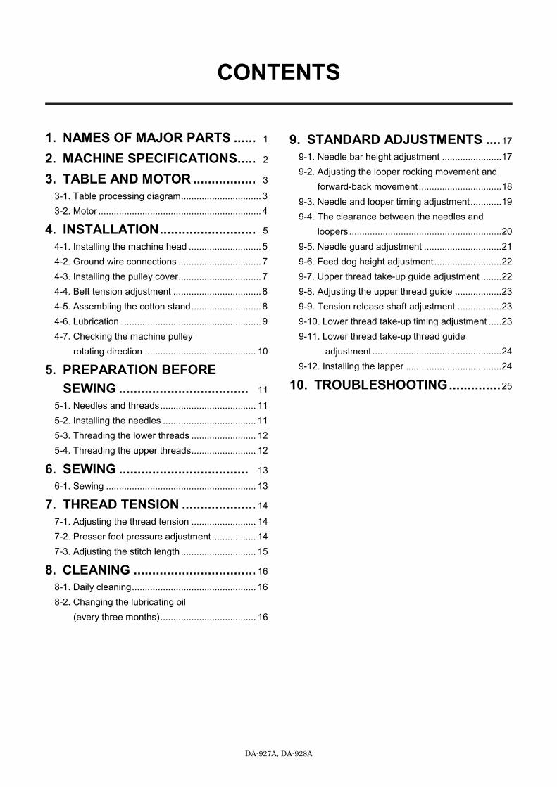
CONTENTS
1. NAMES OF MAJOR PARTS ...... 1
2. MACHINE SPECIFICATIONS ..... 2 3. TABLE AND MOTOR ................. 3
3-1. Table processing diagram ............................... 3 3-2. Motor ............................................................... 4
4. INSTALLATION .......................... 5 4-1. Installing the machine head ............................ 5 4-2. Ground wire connections ................................ 7 4-3. Installing the pulley cover ................................ 7 4-4. BeIt tension adjustment .................................. 8 4-5. Assembling the cotton stand ........................... 8 4-6. Lubrication....................................................... 9 4-7. Checking the machine pulley
rotating direction ........................................... 10
5. PREPARATION BEFORE SEWING ................................... 11
5-1. Needles and threads ..................................... 11 5-2. Installing the needles .................................... 11 5-3. Threading the lower threads ......................... 12 5-4. Threading the upper threads ......................... 12
6. SEWING ................................... 13 6-1. Sewing .......................................................... 13
7. THREAD TENSION .................... 14 7-1. Adjusting the thread tension ......................... 14 7-2. Presser foot pressure adjustment ................. 14 7-3. Adjusting the stitch length ............................. 15
8. CLEANING ................................. 16 8-1. Daily cleaning ................................................ 16 8-2. Changing the lubricating oil
(every three months) ..................................... 16
9. STANDARD ADJUSTMENTS .... 17 9-1. Needle bar height adjustment ....................... 17 9-2. Adjusting the looper rocking movement and
forward-back movement ................................ 18 9-3. Needle and looper timing adjustment ............ 19 9-4. The clearance between the needles and
loopers ........................................................... 20 9-5. Needle guard adjustment .............................. 21 9-6. Feed dog height adjustment .......................... 22 9-7. Upper thread take-up guide adjustment ........ 22 9-8. Adjusting the upper thread guide .................. 23 9-9. Tension release shaft adjustment ................. 23 9-10. Lower thread take-up timing adjustment ..... 23 9-11. Lower thread take-up thread guide
adjustment .................................................. 24 9-12. Installing the lapper ..................................... 24
10. TROUBLESHOOTING .............. 25
DA-927A, DA-928A
1. NAMES OF MAJOR PARTS
1
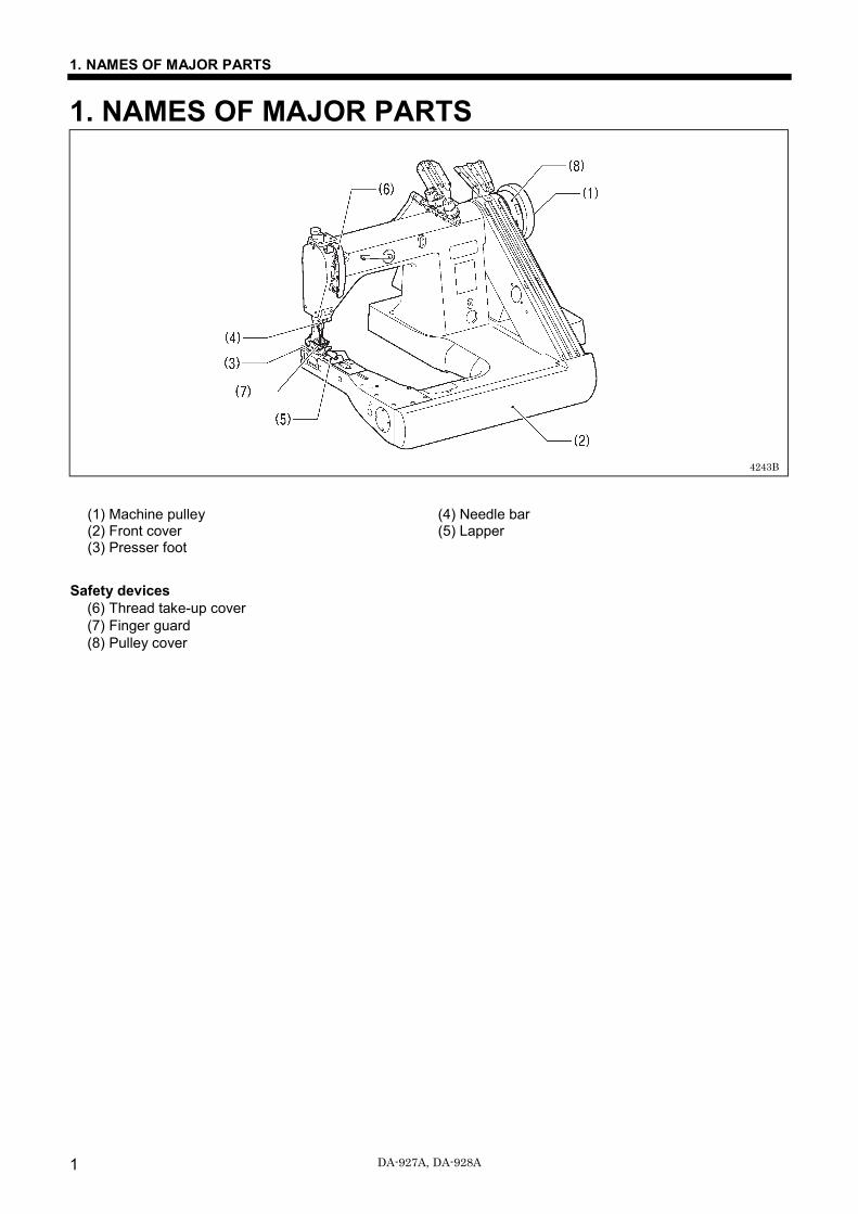
1. NAMES OF MAJOR PARTS
(1) Machine pulley (4) Needle bar (2) Front cover (5) Lapper (3) Presser foot
Safety devices (6) Thread take-up cover (7) Finger guard (8) Pulley cover
4243B
DA-927A, DA-928A
2. MACHINE SPECIFICATIONS
2
2. MACHINE SPECIFICATIONS
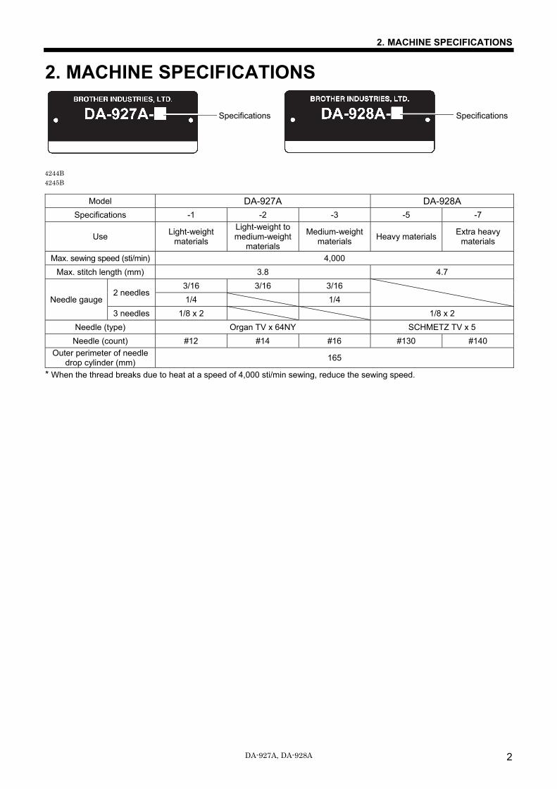
Model DA-927A DA-928A Specifications -1 -2 -3 -5 -7
Use Light-weight materials
Light-weight to medium-weight
materials
Medium-weight materials Heavy materials Extra heavy
materials
Max. sewing speed (sti/min) 4,000 Max. stitch length (mm) 3.8 4.7
Needle gauge 2 needles
3/16 3/16 3/16
1/4 1/4 3 needles 1/8 x 2 1/8 x 2
Needle (type) Organ TV x 64NY SCHMETZ TV x 5 Needle (count) #12 #14 #16 #130 #140
Outer perimeter of needle drop cylinder (mm) 165
* When the thread breaks due to heat at a speed of 4,000 sti/min sewing, reduce the sewing speed.
Specifications Specifications
4244B 4245B
3. TABLE AND MOTOR
DA-927A, DA-928A 3
3. TABLE AND MOTOR
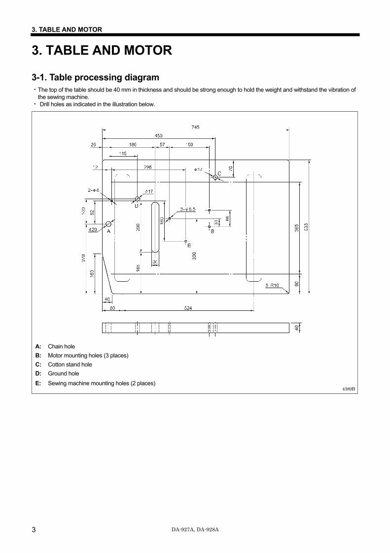
3-1. Table processing diagram ・The top of the table should be 40 mm in thickness and should be strong enough to hold the weight and withstand the vibration of
the sewing machine. ・ Drill holes as indicated in the illustration below.
A: Chain hole
B: Motor mounting holes (3 places)
C: Cotton stand hole
D: Ground hole
E: Sewing machine mounting holes (2 places)
4389B
3. TABLE AND MOTOR
DA-927A, DA-928A 4
3-2. Motor
CAUTION All cords should be secured at least 25 mm away from any moving parts. Furthermore, do not excessively bend the cords or secure them too firmly with staples. If this is not observed, fire or electric shocks may result.
Install the correct belt cover which corresponds to the motor being used.
<Motor>
・ Use a 400-watt 2-pole clutch motor. ・ Refer to the instruction manual for the motor for details on installing and using the motor.
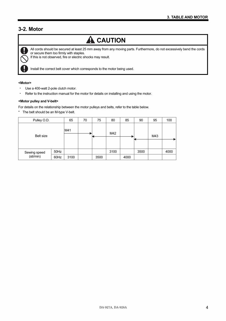
<Motor pulley and V-belt>
For details on the relationship between the motor pulleys and belts, refer to the table below.
* The belt should be an M-type V-belt.
Pulley O.D. 65 70 75 80 85 90 95 100
Belt size
Sewing speed (sti/min)
50Hz 3100 3500 4000
60Hz 3100 3500 4000
M42 M43
M41
4. INSTALLATION
5 DA-927A, DA-928A
4. INSTALLATION
CAUTION Machine installation should only be carried out by a qualified technician.
Contact your Brother dealer or a qualified electrician for any electrical work that may need to be done.
The sewing machine weighs approximately 49 kg. The installation should be carried out by two or more people.
Do not connect the power cord until installation is complete. The machine may operate if the treadle is depressed by mistake, which could result in injury.
Be sure to connect the ground. If the ground connection is not secure, you run a high risk of receiving a serious electric shock, and problems with correct operation may also occur.
Install the pulley cover to the machine head.
<Cautions regarding table and legs> When installing the legs to the table, adjust the heights of the legs so that the machine head can be set up horizontally. If the machine head is not horizontal, it will adversely affect the lubrication of the needle bar mechanism, and seizing or abnormal wear may occur.
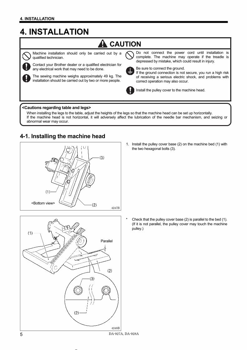
4-1. Installing the machine head 1. Install the pulley cover base (2) on the machine bed (1) with
the two hexagonal bolts (3).
* Check that the pulley cover base (2) is parallel to the bed (1). (If it is not parallel, the pulley cover may touch the machine pulley.)
4248B
4247B
<Bottom view>
Parallel
4. INSTALLATION
6 DA-927A, DA-928A
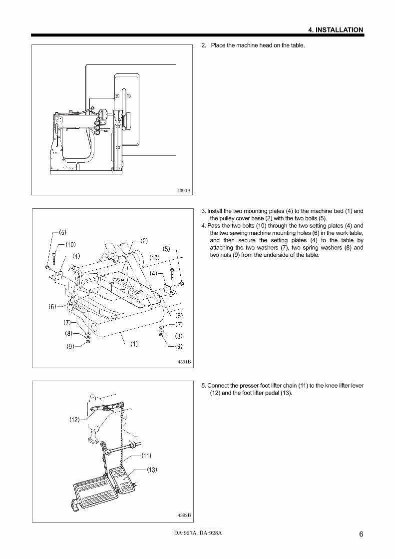
2. Place the machine head on the table.
3. Install the two mounting plates (4) to the machine bed (1) and the pulley cover base (2) with the two bolts (5).
4. Pass the two bolts (10) through the two setting plates (4) and the two sewing machine mounting holes (6) in the work table, and then secure the setting plates (4) to the table by attaching the two washers (7), two spring washers (8) and two nuts (9) from the underside of the table.
5. Connect the presser foot lifter chain (11) to the knee lifter lever (12) and the foot lifter pedal (13).
4390B
4392B
4391B
4. INSTALLATION
7 DA-927A, DA-928A
4-2. Ground wire connections
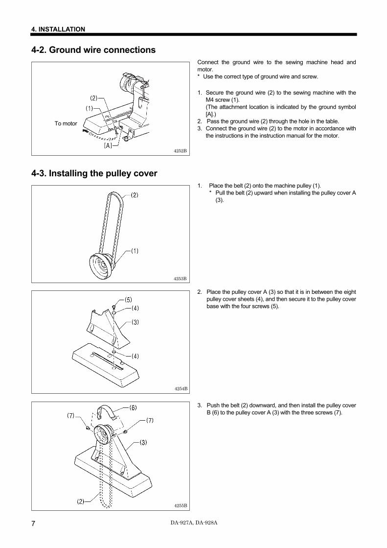
Connect the ground wire to the sewing machine head and motor. * Use the correct type of ground wire and screw. 1. Secure the ground wire (2) to the sewing machine with the
M4 screw (1). (The attachment location is indicated by the ground symbol [A].)
2. Pass the ground wire (2) through the hole in the table. 3. Connect the ground wire (2) to the motor in accordance with
the instructions in the instruction manual for the motor.
4-3. Installing the pulley cover
1. Place the belt (2) onto the machine pulley (1). * Pull the belt (2) upward when installing the pulley cover A
(3).
2. Place the pulley cover A (3) so that it is in between the eight pulley cover sheets (4), and then secure it to the pulley cover base with the four screws (5).
3. Push the belt (2) downward, and then install the pulley cover B (6) to the pulley cover A (3) with the three screws (7).
4252B
4253B
4255B
4254B
To motor
4. INSTALLATION
8 DA-927A, DA-928A
4-4. Belt tension adjustment
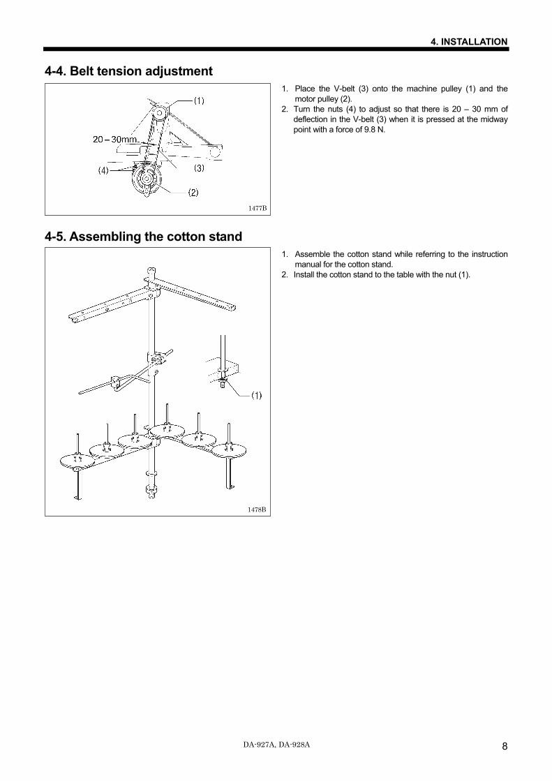
1. Place the V-belt (3) onto the machine pulley (1) and the motor pulley (2).
2. Turn the nuts (4) to adjust so that there is 20 – 30 mm of deflection in the V-belt (3) when it is pressed at the midway point with a force of 9.8 N.
4-5. Assembling the cotton stand
1. Assemble the cotton stand while referring to the instruction manual for the cotton stand.
2. Install the cotton stand to the table with the nut (1).
1477B
1478B
4. INSTALLATION
9 DA-927A, DA-928A
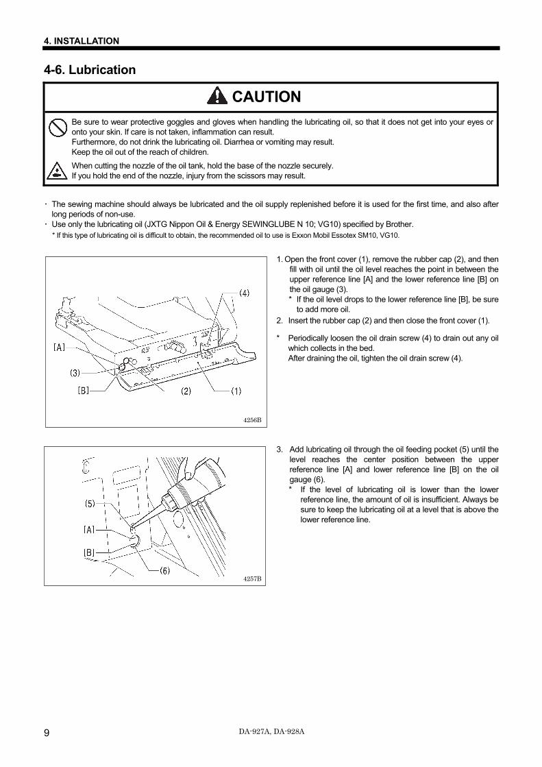
4-6. Lubrication
CAUTION Be sure to wear protective goggles and gloves when handling the lubricating oil, so that it does not get into your eyes or onto your skin. If care is not taken, inflammation can result. Furthermore, do not drink the lubricating oil. Diarrhea or vomiting may result. Keep the oil out of the reach of children.
When cutting the nozzle of the oil tank, hold the base of the nozzle securely. If you hold the end of the nozzle, injury from the scissors may result.
・ The sewing machine should always be lubricated and the oil supply replenished before it is used for the first time, and also after
long periods of non-use. ・ Use only the lubricating oil (JXTG Nippon Oil & Energy SEWINGLUBE N 10; VG10) specified by Brother.
* If this type of lubricating oil is difficult to obtain, the recommended oil to use is Exxon Mobil Essotex SM10, VG10.
1. Open the front cover (1), remove the rubber cap (2), and then
fill with oil until the oil level reaches the point in between the upper reference line [A] and the lower reference line [B] on the oil gauge (3). * If the oil level drops to the lower reference line [B], be sure
to add more oil. 2. Insert the rubber cap (2) and then close the front cover (1).
* Periodically loosen the oil drain screw (4) to drain out any oil which collects in the bed. After draining the oil, tighten the oil drain screw (4).
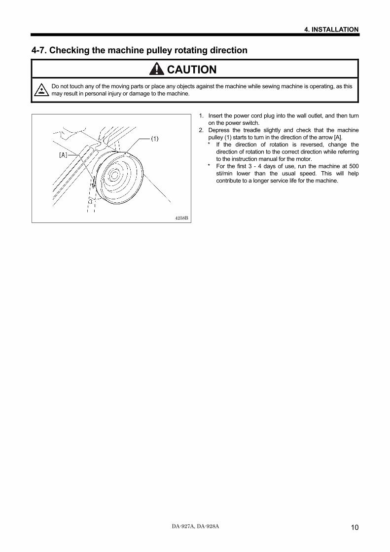
3. Add lubricating oil through the oil feeding pocket (5) until the level reaches the center position between the upper reference line [A] and lower reference line [B] on the oil gauge (6). * If the level of lubricating oil is lower than the lower
reference line, the amount of oil is insufficient. Always be sure to keep the lubricating oil at a level that is above the lower reference line.
4257B
4256B
4. INSTALLATION
10 DA-927A, DA-928A
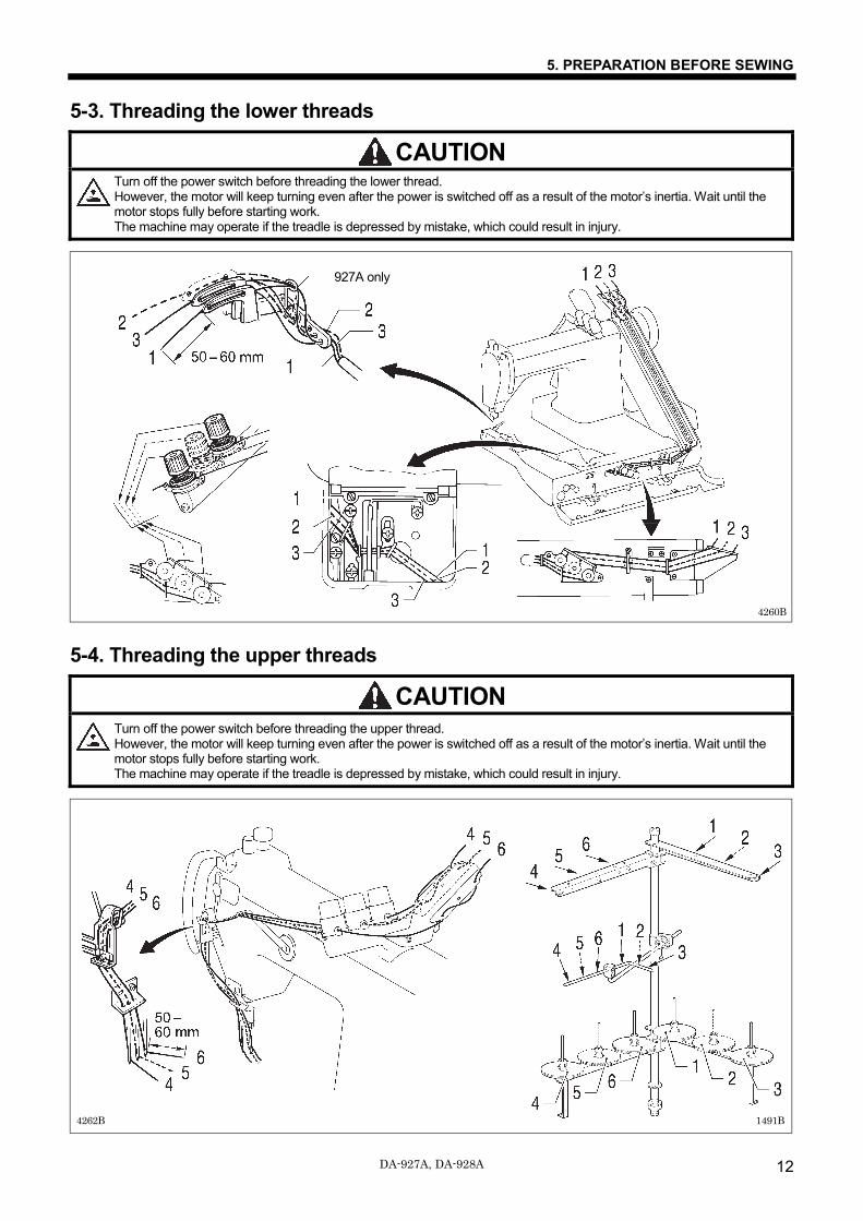
4-7. Checking the machine pulley rotating direction
CAUTION Do not touch any of the moving parts or place any objects against the machine while sewing machine is operating, as this may result in personal injury or damage to the machine.
1. Insert the power cord plug into the wall outlet, and then turn on the power switch.
2. Depress the treadle slightly and check that the machine pulley (1) starts to turn in the direction of the arrow [A]. * If the direction of rotation is reversed, change the
direction of rotation to the correct direction while referring to the instruction manual for the motor.
* For the first 3 - 4 days of use, run the machine at 500 sti/min lower than the usual speed. This will help contribute to a longer service life for the machine.
4258B

5. PREPARATION BEFORE SEWING
11 DA-927A, DA-928A
5. PREPARATION BEFORE SEWING 5-1. Needles and threads The needle and threads to be used vary depending on sewing conditions. Select the correct ones by referring to the table below.
Needle count Thread
Upper thread Lower thread TV x 64#12 (Organ)
TV x 5#80 (SCHMETZ) Spun yarn #60 Spun yarn #80
TV x 64#14 (Organ) TV x 5#90 (SCHMETZ)
Spun yarn #60 Spun yarn #60
TV x 64#16 (Organ) TV x 5#100 (SCHMETZ)
Spun yarn #50 Spun yarn #50
TV x 64#21(Organ) TV x 5#130 (SCHMETZ)
Spun yarn #30 Spun yarn #30
TV x 64#22(Organ) TV x 5#140 (SCHMETZ)
Spun yarn #20 Spun yarn #30
5-2. Installing the needles
CAUTION Turn off the power switch before installing the needle. However, the motor will keep turning even after the power is switched off as a result of the motor’s inertia. Wait until the motor stops fully before starting work. The machine may operate if the treadle is depressed by mistake, which could result in injury.
1. Turn the machine pulley until needle clamp (1) is raised to the
highest position. 2. Loosen the three set screws (2), hold the three needles (3)
with their long grooved side facing front, insert them into the needle clamp (1) all the way, and fasten the needle with the three set screws (2).
4259B
5. PREPARATION BEFORE SEWING
12 DA-927A, DA-928A
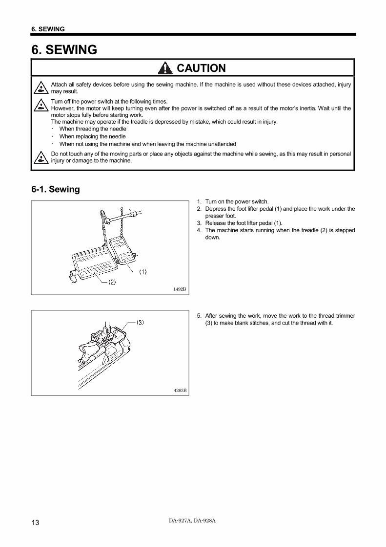
5-3. Threading the lower threads
CAUTION Turn off the power switch before threading the lower thread. However, the motor will keep turning even after the power is switched off as a result of the motor’s inertia. Wait until the motor stops fully before starting work. The machine may operate if the treadle is depressed by mistake, which could result in injury.
5-4. Threading the upper threads
CAUTION Turn off the power switch before threading the upper thread. However, the motor will keep turning even after the power is switched off as a result of the motor’s inertia. Wait until the motor stops fully before starting work. The machine may operate if the treadle is depressed by mistake, which could result in injury.
1491B 4262B
4260B
927A only
6. SEWING
13 DA-927A, DA-928A
6. SEWING CAUTION
Attach all safety devices before using the sewing machine. If the machine is used without these devices attached, injury may result.
Turn off the power switch at the following times. However, the motor will keep turning even after the power is switched off as a result of the motor’s inertia. Wait until the motor stops fully before starting work. The machine may operate if the treadle is depressed by mistake, which could result in injury. ・ When threading the needle ・ When replacing the needle ・ When not using the machine and when leaving the machine unattended
Do not touch any of the moving parts or place any objects against the machine while sewing, as this may result in personal injury or damage to the machine.
6-1. Sewing 1. Turn on the power switch. 2. Depress the foot lifter pedal (1) and place the work under the
presser foot. 3. Release the foot lifter pedal (1). 4. The machine starts running when the treadle (2) is stepped
down.
5. After sewing the work, move the work to the thread trimmer (3) to make blank stitches, and cut the thread with it.
4263B
1492B
7. THREAD TENSION
14 DA-927A, DA-928A
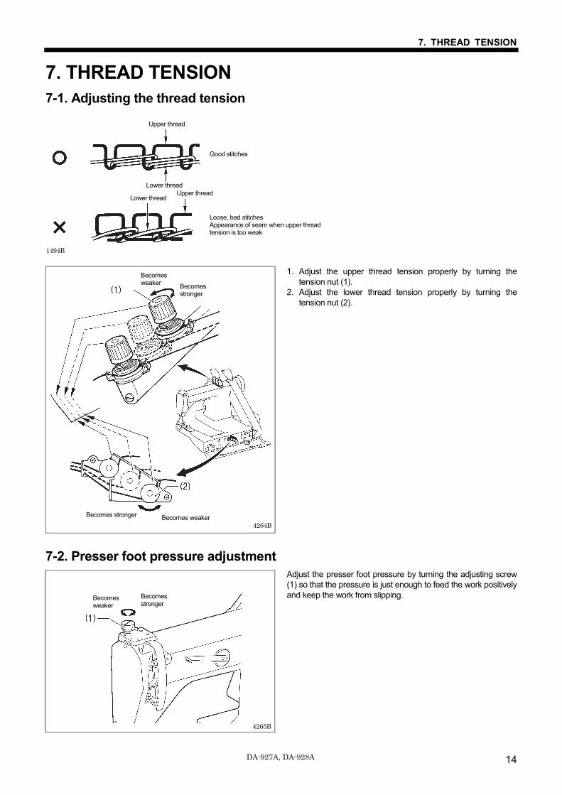
7. THREAD TENSION 7-1. Adjusting the thread tension
1. Adjust the upper thread tension properly by turning the tension nut (1).
2. Adjust the lower thread tension properly by turning the tension nut (2).
7-2. Presser foot pressure adjustment Adjust the presser foot pressure by turning the adjusting screw (1) so that the pressure is just enough to feed the work positively and keep the work from slipping.
Good stitches
Loose, bad stitches Appearance of seam when upper thread tension is too weak
1494B
4264B
Becomes weaker
Upper thread
Lower thread Lower thread
Upper thread
Becomes weaker
Becomes stronger
Becomes stronger
4265B
Becomes weaker
Becomes stronger
7. THREAD TENSION
15 DA-927A, DA-928A
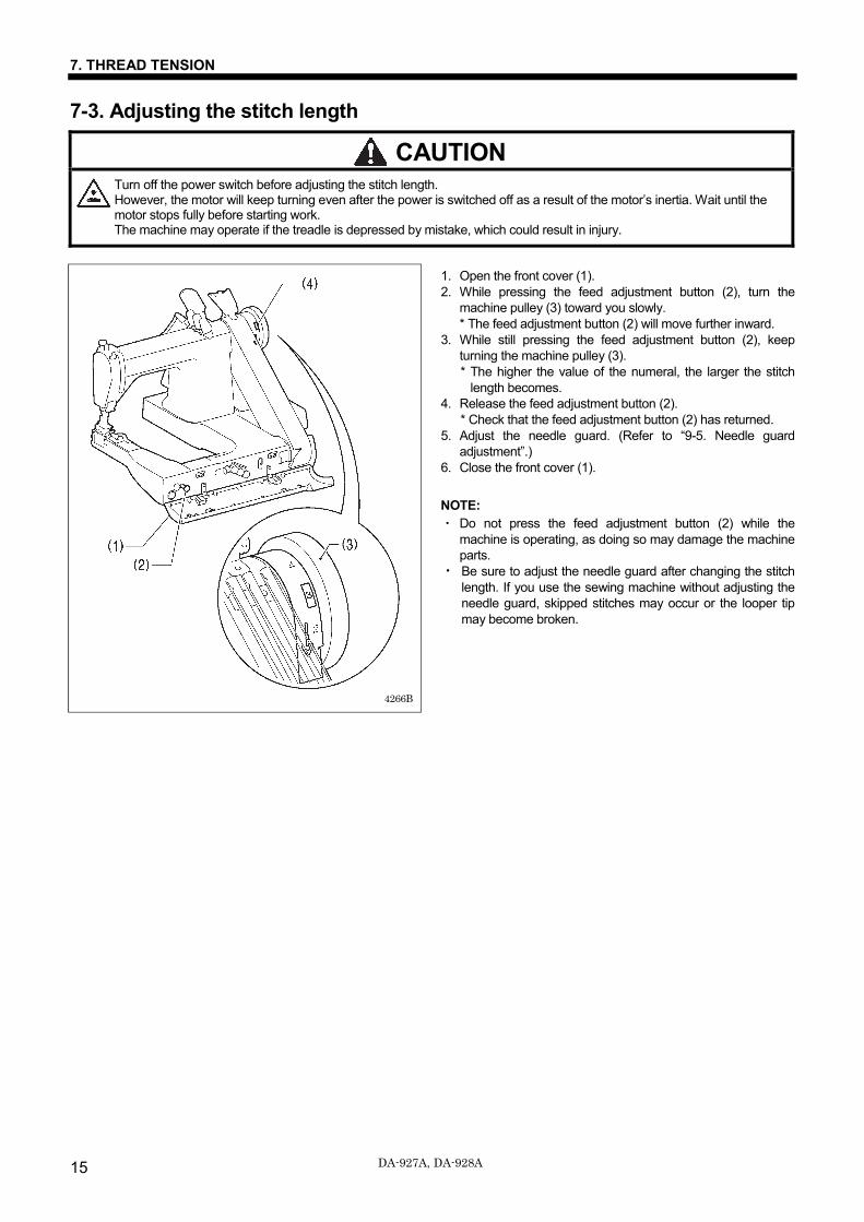
7-3. Adjusting the stitch length
CAUTION Turn off the power switch before adjusting the stitch length. However, the motor will keep turning even after the power is switched off as a result of the motor’s inertia. Wait until the motor stops fully before starting work. The machine may operate if the treadle is depressed by mistake, which could result in injury.
1. Open the front cover (1). 2. While pressing the feed adjustment button (2), turn the
machine pulley (3) toward you slowly. * The feed adjustment button (2) will move further inward.
3. While still pressing the feed adjustment button (2), keep turning the machine pulley (3). * The higher the value of the numeral, the larger the stitch
length becomes. 4. Release the feed adjustment button (2).
* Check that the feed adjustment button (2) has returned. 5. Adjust the needle guard. (Refer to “9-5. Needle guard
adjustment”.) 6. Close the front cover (1). NOTE: ・ Do not press the feed adjustment button (2) while the
machine is operating, as doing so may damage the machine parts.
・ Be sure to adjust the needle guard after changing the stitch length. If you use the sewing machine without adjusting the needle guard, skipped stitches may occur or the looper tip may become broken.
4266B
8. CLEANING
16 DA-927A, DA-928A
8. CLEANING The following cleaning operations should be carried out each day in order to maintain the performance of this machine and to ensure a long service life. Furthermore, if the sewing machine has not been used for a long period of time, carry out the following cleaning procedures before using it again.
CAUTION Turn off the power switch before carrying out cleaning. The motor will keep turning even after the power is switched off as a result of the motor’s inertia. Wait until the motor stops fully before starting work. The machine may operate if the treadle is depressed by mistake, which could result in injury.
Be sure to wear protective goggles and gloves when handling the lubricating oil, so that it does not get into your eyes or onto your skin. If care is not taken, inflammation can result. Furthermore, do not drink the lubricating oil. Diarrhea or vomiting may result. Keep the oil out of the reach of children.
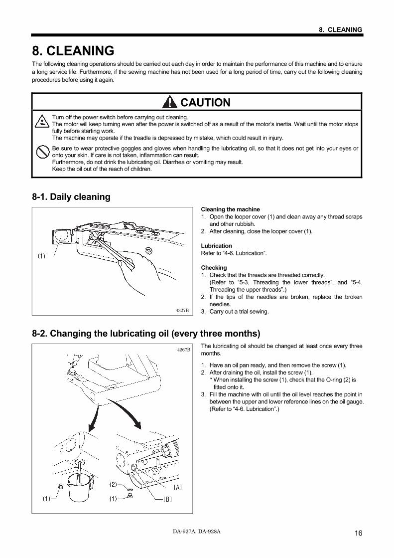
8-1. Daily cleaning Cleaning the machine 1. Open the looper cover (1) and clean away any thread scraps
and other rubbish. 2. After cleaning, close the looper cover (1). Lubrication Refer to “4-6. Lubrication”. Checking 1. Check that the threads are threaded correctly.
(Refer to “5-3. Threading the lower threads”, and “5-4. Threading the upper threads”.)
2. If the tips of the needles are broken, replace the broken needles.
3. Carry out a trial sewing.
8-2. Changing the lubricating oil (every three months) The lubricating oil should be changed at least once every three months.
1. Have an oil pan ready, and then remove the screw (1). 2. After draining the oil, install the screw (1).
* When installing the screw (1), check that the O-ring (2) is fitted onto it.
3. Fill the machine with oil until the oil level reaches the point in between the upper and lower reference lines on the oil gauge. (Refer to “4-6. Lubrication”.)
4327B
4267B
9. STANDARD ADJUSTMENTS
DA-927A, DA-928A 17
9. STANDARD ADJUSTMENTS CAUTION
Maintenance and inspection of the sewing machine should only be carried out by qualified personnel.
Ask your Brother dealer or a qualified electrician to carry out any maintenance and inspection of the electrical system.
Turn off the power switch and disconnect the power cord from the wall outlet at the following times. However, the motor will keep turning even after the power is switched off as a result of the motor’s inertia. Wait until the motor stops fully before starting work. The machine may operate if the treadle is depressed by mistake, which could result in injury.
• When carrying out inspection, adjustment and maintenance
• When replacing consumable parts such as the looper
If any safety devices have been removed, be absolutely sure to re-install them to their original positions and check that they operate correctly before using the machine.
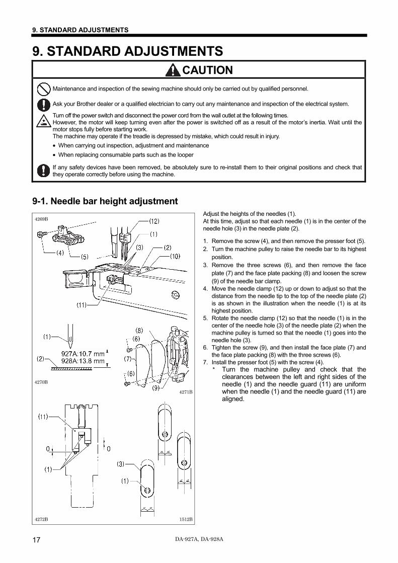
9-1. Needle bar height adjustment Adjust the heights of the needles (1). At this time, adjust so that each needle (1) is in the center of the needle hole (3) in the needle plate (2).
1. Remove the screw (4), and then remove the presser foot (5). 2. Turn the machine pulley to raise the needle bar to its highest
position. 3. Remove the three screws (6), and then remove the face
plate (7) and the face plate packing (8) and loosen the screw (9) of the needle bar clamp.
4. Move the needle clamp (12) up or down to adjust so that the distance from the needle tip to the top of the needle plate (2) is as shown in the illustration when the needle (1) is at its highest position.
5. Rotate the needle clamp (12) so that the needle (1) is in the center of the needle hole (3) of the needle plate (2) when the machine pulley is turned so that the needle (1) goes into the needle hole (3).
6. Tighten the screw (9), and then install the face plate (7) and the face plate packing (8) with the three screws (6).
7. Install the presser foot (5) with the screw (4). * Turn the machine pulley and check that the
clearances between the left and right sides of the needle (1) and the needle guard (11) are uniform when the needle (1) and the needle guard (11) are aligned.
1512B
4270B
4271B
4272B
4269B
9. STANDARD ADJUSTMENTS
18 DA-927A, DA-928A
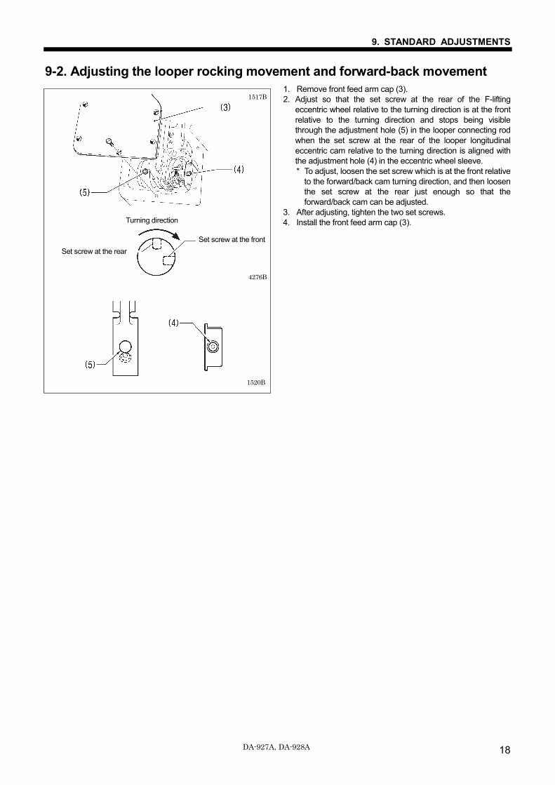
9-2. Adjusting the looper rocking movement and forward-back movement 1. Remove front feed arm cap (3). 2. Adjust so that the set screw at the rear of the F-lifting
eccentric wheel relative to the turning direction is at the front relative to the turning direction and stops being visible through the adjustment hole (5) in the looper connecting rod when the set screw at the rear of the looper longitudinal eccentric cam relative to the turning direction is aligned with the adjustment hole (4) in the eccentric wheel sleeve. * To adjust, loosen the set screw which is at the front relative
to the forward/back cam turning direction, and then loosen the set screw at the rear just enough so that the forward/back cam can be adjusted.
3. After adjusting, tighten the two set screws. 4. Install the front feed arm cap (3).
Turning direction
4276B
1517B
Set screw at the rear
Set screw at the front
1520B
Turning direction
9. STANDARD ADJUSTMENTS
DA-927A, DA-928A 19
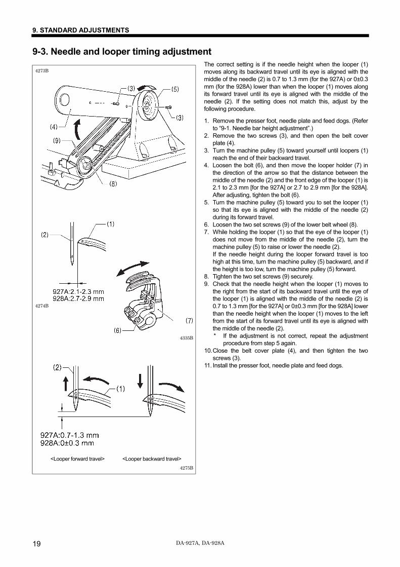
9-3. Needle and looper timing adjustment The correct setting is if the needle height when the looper (1) moves along its backward travel until its eye is aligned with the middle of the needle (2) is 0.7 to 1.3 mm (for the 927A) or 0±0.3 mm (for the 928A) lower than when the looper (1) moves along its forward travel until its eye is aligned with the middle of the needle (2). If the setting does not match this, adjust by the following procedure. 1. Remove the presser foot, needle plate and feed dogs. (Refer
to “9-1. Needle bar height adjustment”.) 2. Remove the two screws (3), and then open the belt cover
plate (4). 3. Turn the machine pulley (5) toward yourself until loopers (1)
reach the end of their backward travel. 4. Loosen the bolt (6), and then move the looper holder (7) in
the direction of the arrow so that the distance between the middle of the needle (2) and the front edge of the looper (1) is 2.1 to 2.3 mm [for the 927A] or 2.7 to 2.9 mm [for the 928A]. After adjusting, tighten the bolt (6).
5. Turn the machine pulley (5) toward you to set the looper (1) so that its eye is aligned with the middle of the needle (2) during its forward travel.
6. Loosen the two set screws (9) of the lower belt wheel (8). 7. While holding the looper (1) so that the eye of the looper (1)
does not move from the middle of the needle (2), turn the machine pulley (5) to raise or lower the needle (2). If the needle height during the looper forward travel is too high at this time, turn the machine pulley (5) backward, and if the height is too low, turn the machine pulley (5) forward.
8. Tighten the two set screws (9) securely. 9. Check that the needle height when the looper (1) moves to
the right from the start of its backward travel until the eye of the looper (1) is aligned with the middle of the needle (2) is 0.7 to 1.3 mm [for the 927A] or 0±0.3 mm [for the 928A] lower than the needle height when the looper (1) moves to the left from the start of its forward travel until its eye is aligned with the middle of the needle (2). * If the adjustment is not correct, repeat the adjustment
procedure from step 5 again. 10. Close the belt cover plate (4), and then tighten the two
screws (3). 11. Install the presser foot, needle plate and feed dogs.
4274B
4335B
4275B <Looper forward travel> <Looper backward travel>
4273B
9. STANDARD ADJUSTMENTS
20 DA-927A, DA-928A
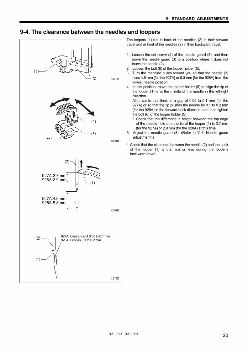
9-4. The clearance between the needles and loopers The loopers (1) run in back of the needles (2) in their forward travel and in front of the needles (2) in their backward travel. 1. Loosen the set screw (4) of the needle guard (3), and then
move the needle guard (3) to a position where it does not touch the needle (2).
2. Loosen the bolt (6) of the looper holder (5). 3. Turn the machine pulley toward you so that the needle (2)
rises 4.9 mm [for the 927A] or 5.3 mm [for the 928A] from the lowest needle position.
4. In this position, move the looper holder (5) to align the tip of the looper (1) is at the middle of the needle in the left-right direction. Also, set to that there is a gap of 0.05 to 0.1 mm (for the 927A) or so that the tip pushes the needle by 0.1 to 0.2 mm (for the 928A) in the forward-back direction, and then tighten the bolt (6) of the looper holder (5). * Check that the difference in height between the top edge
of the needle hole and the tip of the looper (1) is 2.7 mm (for the 927A) or 2.9 mm (for the 928A) at this time.
5. Adjust the needle guard (3). (Refer to “9-5. Needle guard adjustment”.)
* Check that the clearance between the needle (2) and the back of the looper (1) is 0.2 mm or less during the looper's backward travel.
4329B
4328B
927A: Clearance of 0.05 to 0.1 mm 928A: Pushes 0.1 to 0.2 mm
4277B
4330B
9. STANDARD ADJUSTMENTS
DA-927A, DA-928A 21
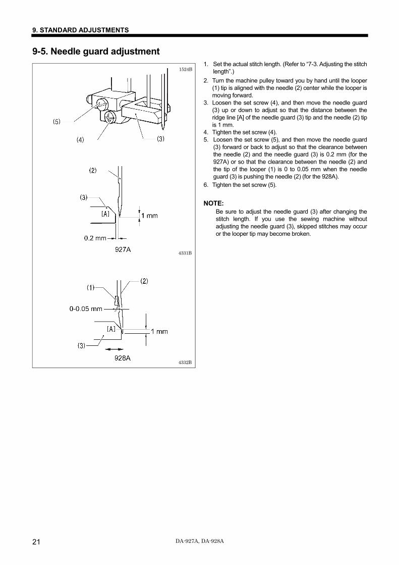
9-5. Needle guard adjustment 1. Set the actual stitch length. (Refer to “7-3. Adjusting the stitch
length”.)
2. Turn the machine pulley toward you by hand until the looper (1) tip is aligned with the needle (2) center while the looper is moving forward.
3. Loosen the set screw (4), and then move the needle guard (3) up or down to adjust so that the distance between the ridge line [A] of the needle guard (3) tip and the needle (2) tip is 1 mm.
4. Tighten the set screw (4). 5. Loosen the set screw (5), and then move the needle guard
(3) forward or back to adjust so that the clearance between the needle (2) and the needle guard (3) is 0.2 mm (for the 927A) or so that the clearance between the needle (2) and the tip of the looper (1) is 0 to 0.05 mm when the needle guard (3) is pushing the needle (2) (for the 928A).
6. Tighten the set screw (5).
NOTE: Be sure to adjust the needle guard (3) after changing the
stitch length. If you use the sewing machine without adjusting the needle guard (3), skipped stitches may occur or the looper tip may become broken.
4332B
1524B
4331B
9. STANDARD ADJUSTMENTS
22 DA-927A, DA-928A
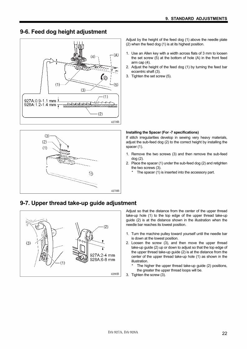
9-6. Feed dog height adjustment Adjust by the height of the feed dog (1) above the needle plate (2) when the feed dog (1) is at its highest position. 1. Use an Allen key with a width across flats of 3 mm to loosen
the set screw (5) at the bottom of hole (A) in the front feed arm cap (4).
2. Adjust the height of the feed dog (1) by turning the feed bar eccentric shaft (3).
3. Tighten the set screw (5).
Installing the Spacer (For -7 specifications) If stitch irregularities develop in sewing very heavy materials, adjust the sub-feed dog (2) to the correct height by installing the spacer (1).
1. Remove the two screws (3) and then remove the sub-feed dog (2).
2. Place the spacer (1) under the sub-feed dog (2) and retighten the two screws (3). * The spacer (1) is inserted into the accessory part.
9-7. Upper thread take-up guide adjustment Adjust so that the distance from the center of the upper thread take-up hole (1) to the top edge of the upper thread take-up guide (2) is at the distance shown in the illustration when the needle bar reaches its lowest position. 1. Turn the machine pulley toward yourself until the needle bar
is down at the lowest position. 2. Loosen the screw (3), and then move the upper thread
take-up guide (2) up or down to adjust so that the top edge of the upper thread take-up guide (2) is at the distance from the center of the upper thread take-up hole (1) as shown in the illustration. * The higher the upper thread take-up guide (2) positions,
the greater the upper thread loops will be. 3. Tighten the screw (3).
針板
4279B
4280B
4278B
9. STANDARD ADJUSTMENTS
DA-927A, DA-928A 23
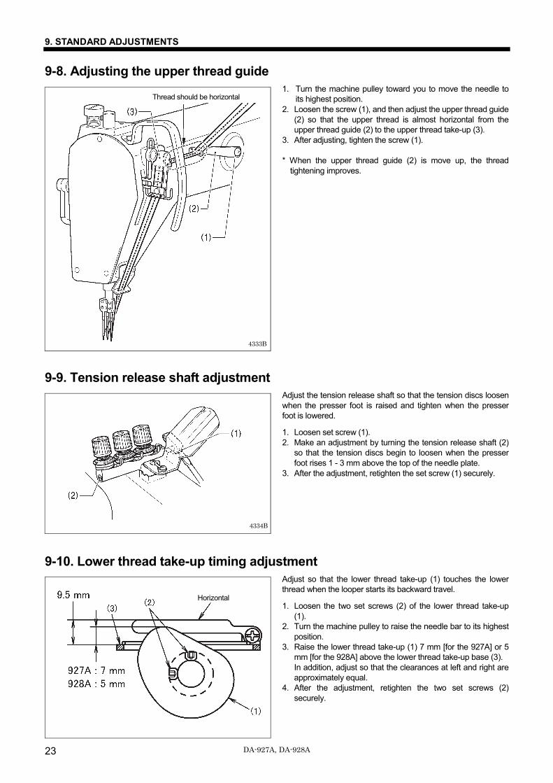
9-8. Adjusting the upper thread guide 1. Turn the machine pulley toward you to move the needle to
its highest position. 2. Loosen the screw (1), and then adjust the upper thread guide
(2) so that the upper thread is almost horizontal from the upper thread guide (2) to the upper thread take-up (3).
3. After adjusting, tighten the screw (1). * When the upper thread guide (2) is move up, the thread
tightening improves.
9-9. Tension release shaft adjustment Adjust the tension release shaft so that the tension discs loosen when the presser foot is raised and tighten when the presser foot is lowered.
1. Loosen set screw (1). 2. Make an adjustment by turning the tension release shaft (2)
so that the tension discs begin to loosen when the presser foot rises 1 - 3 mm above the top of the needle plate.
3. After the adjustment, retighten the set screw (1) securely.
9-10. Lower thread take-up timing adjustment Adjust so that the lower thread take-up (1) touches the lower thread when the looper starts its backward travel. 1. Loosen the two set screws (2) of the lower thread take-up
(1). 2. Turn the machine pulley to raise the needle bar to its highest
position. 3. Raise the lower thread take-up (1) 7 mm [for the 927A] or 5
mm [for the 928A] above the lower thread take-up base (3). In addition, adjust so that the clearances at left and right are approximately equal.
4. After the adjustment, retighten the two set screws (2) securely.
4334B
Thread should be horizontal
4333B
Horizontal
9. STANDARD ADJUSTMENTS
24 DA-927A, DA-928A
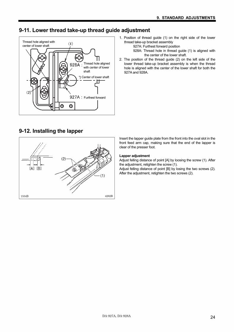
9-11. Lower thread take-up thread guide adjustment 1. Position of thread guide (1) on the right side of the lower
thread take-up bracket assembly 927A: Furthest forward position 928A: Thread hole in thread guide (1) is aligned with
the center of the lower shaft. 2. The position of the thread guide (2) on the left side of the
lower thread take-up bracket assembly is when the thread hole is aligned with the center of the lower shaft for both the 927A and 928A.
9-12. Installing the lapper Insert the lapper guide plate from the front into the oval slot in the front feed arm cap, making sure that the end of the lapper is clear of the presser foot. Lapper adjustment Adjust felling distance of point [A] by loosing the screw (1). After the adjustment, retighten the screw (1). Adjust felling distance of point [B] by losing the two screws (2). After the adjustment, retighten the two screws (2).
4282B 1534B
糸穴下軸中心一致
下軸中心
最前
Center of lower shaft
Thread hole aligned with center of lower shaft
Furthest forward
Thread hole aligned with center of lower shaft
10. TROUBLESHOOTING
DA-927A, DA-928A 25
10. TROUBLESHOOTING
If there is a problem with operation, first check that the threads are correctly threaded and that the needle is correctly installed. Please check the following points before calling for repairs or service. If the following remedies do not fix the problem, turn off the power switch and consult a qualified technician or the place of
purchase.
CAUTION Turn off the power switch and disconnect the power cord from the wall outlet before carrying out troubleshooting. The motor will keep turning even after the power is switched off as a result of the motor’s inertia. Wait until the motor stops fully before starting work. The machine may operate if the treadle is depressed by mistake, which could result in injury.
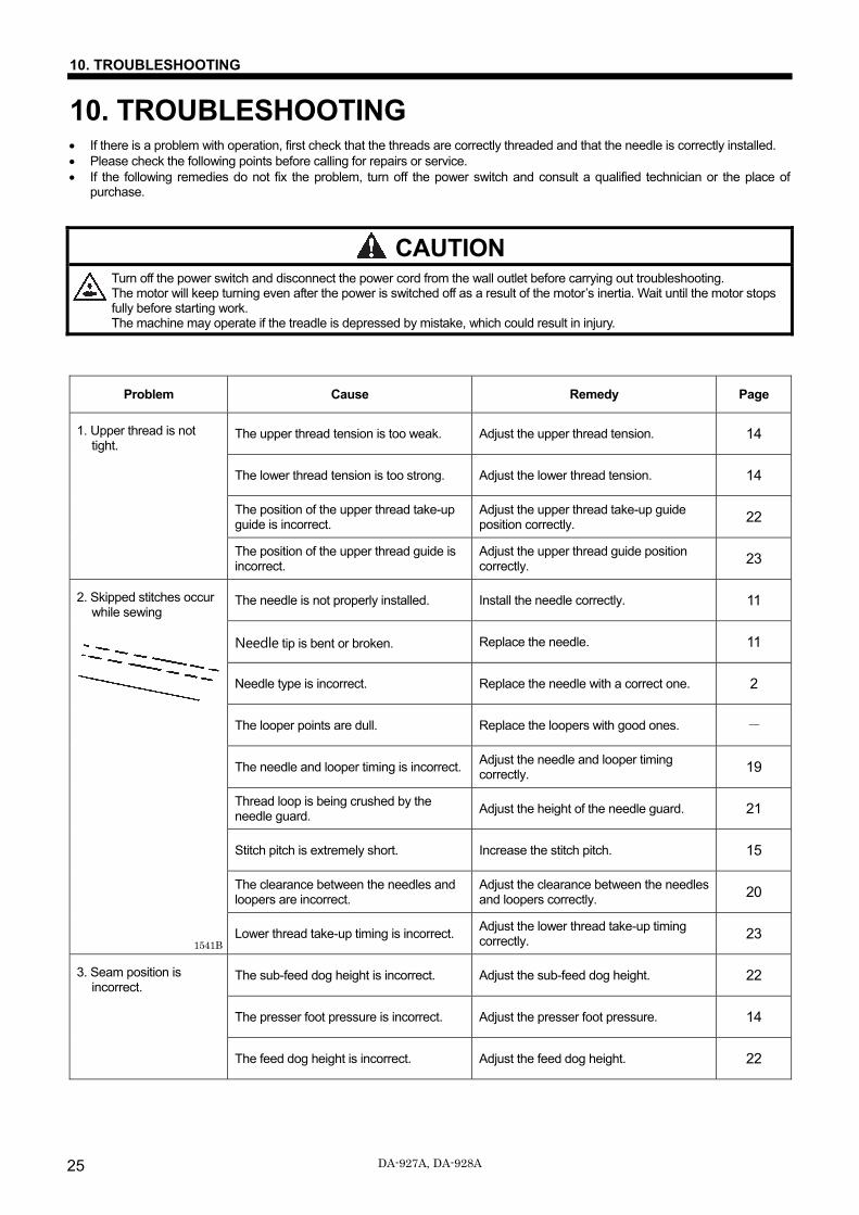
Problem Cause Remedy Page
1. Upper thread is not tight.
The upper thread tension is too weak. Adjust the upper thread tension. 14
The lower thread tension is too strong. Adjust the lower thread tension. 14
The position of the upper thread take-up guide is incorrect.
Adjust the upper thread take-up guide position correctly. 22
The position of the upper thread guide is incorrect.
Adjust the upper thread guide position correctly. 23
2. Skipped stitches occur while sewing
The needle is not properly installed. Install the needle correctly. 11
Needle tip is bent or broken. Replace the needle. 11
Needle type is incorrect. Replace the needle with a correct one. 2
The looper points are dull. Replace the loopers with good ones. -
The needle and looper timing is incorrect. Adjust the needle and looper timing correctly. 19
Thread loop is being crushed by the needle guard.
Adjust the height of the needle guard. 21
Stitch pitch is extremely short. Increase the stitch pitch. 15
The clearance between the needles and loopers are incorrect.
Adjust the clearance between the needles and loopers correctly. 20
Lower thread take-up timing is incorrect. Adjust the lower thread take-up timing correctly. 23
3. Seam position is incorrect.
The sub-feed dog height is incorrect. Adjust the sub-feed dog height. 22
The presser foot pressure is incorrect. Adjust the presser foot pressure. 14
The feed dog height is incorrect. Adjust the feed dog height. 22
1541B
10. TROUBLESHOOTING
DA-927A, DA-928A 26
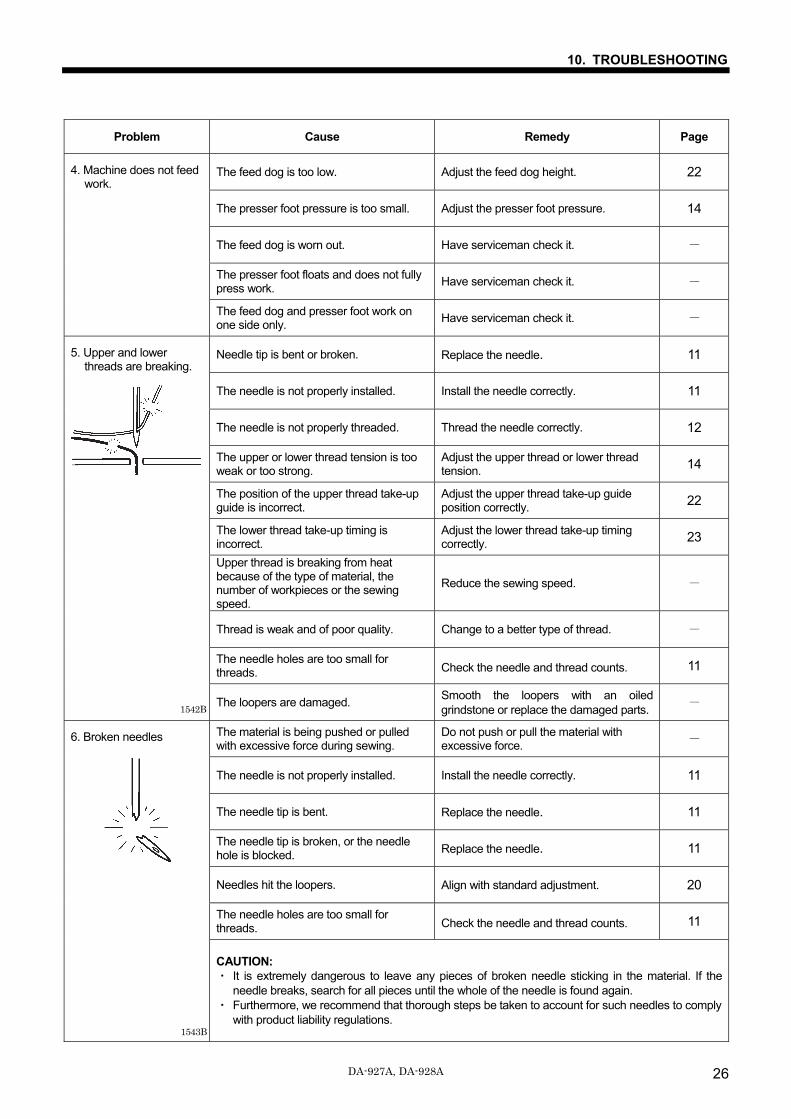
Problem Cause Remedy Page
4. Machine does not feed work.
The feed dog is too low. Adjust the feed dog height. 22
The presser foot pressure is too small. Adjust the presser foot pressure. 14
The feed dog is worn out. Have serviceman check it. -
The presser foot floats and does not fully press work.
Have serviceman check it. -
The feed dog and presser foot work on one side only. Have serviceman check it. -
5. Upper and lower threads are breaking.
Needle tip is bent or broken. Replace the needle. 11
The needle is not properly installed. Install the needle correctly. 11
The needle is not properly threaded. Thread the needle correctly. 12
The upper or lower thread tension is too weak or too strong.
Adjust the upper thread or lower thread tension. 14
The position of the upper thread take-up guide is incorrect.
Adjust the upper thread take-up guide position correctly. 22
The lower thread take-up timing is incorrect.
Adjust the lower thread take-up timing correctly. 23
Upper thread is breaking from heat because of the type of material, the number of workpieces or the sewing speed.
Reduce the sewing speed. -
Thread is weak and of poor quality. Change to a better type of thread. -
The needle holes are too small for threads. Check the needle and thread counts. 11
The loopers are damaged. Smooth the loopers with an oiled grindstone or replace the damaged parts. -
6. Broken needles
The material is being pushed or pulled with excessive force during sewing.
Do not push or pull the material with excessive force. -
The needle is not properly installed. Install the needle correctly. 11
The needle tip is bent. Replace the needle. 11
The needle tip is broken, or the needle hole is blocked. Replace the needle. 11
Needles hit the loopers. Align with standard adjustment. 20
The needle holes are too small for threads. Check the needle and thread counts. 11
CAUTION: ・ It is extremely dangerous to leave any pieces of broken needle sticking in the material. If the
needle breaks, search for all pieces until the whole of the needle is found again. ・ Furthermore, we recommend that thorough steps be taken to account for such needles to comply
with product liability regulations.
1542B
1543B
INSTRUCTION MANUAL
© 2018-2020 Brother Industries, Ltd. All Rights Reserved. This is the original instructions.
DA-927A, DA-928AI9031299B E2020.05.B (2)
* Please note that the contents of this manual may differ slightly from the actual product purchased as a result of product improvements.