Embed Size (px)
Citation preview
g GE MULTILIN
12/22/2004 D:\Documenty\gepm\Russia\kep\D60-setting example.doc Rev. A1Ilia Voloh
D60 Line Distance relay Setting Example
Provided for D60 model D60-C00-HCH-F8A-H6P-M6P-P6C
Primary FunctionsThis relay provides 3-pole tripping functions and initiates autoreclosure. The primary purpose of this relay is 3-zone stepped line phase and ground distance protection, pilot Permissive Overreaching Tripping scheme. Distance is blocked by VT Fuse Failure, Power Swing Detect and load Enchroachment. Line Pickup (switch onto the fault) backs up distance on line energization. Autoreclose can be initiated externally (from L90 relay, for example) and is supervised by synchrocheck. Relay has inputs from breaker auxiliary contacts, panel pushbuttons, RTU etc, also outputs for trip, alarm, status that are collected by the HMI and RTU.
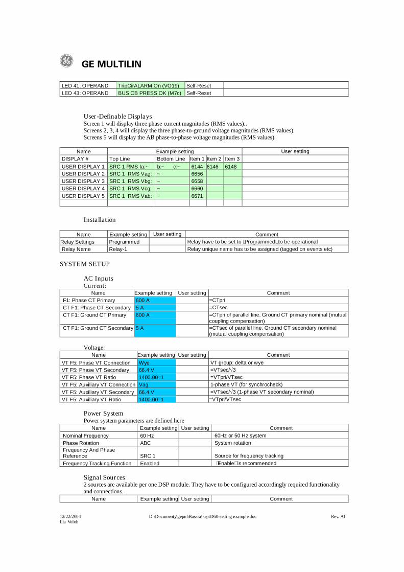
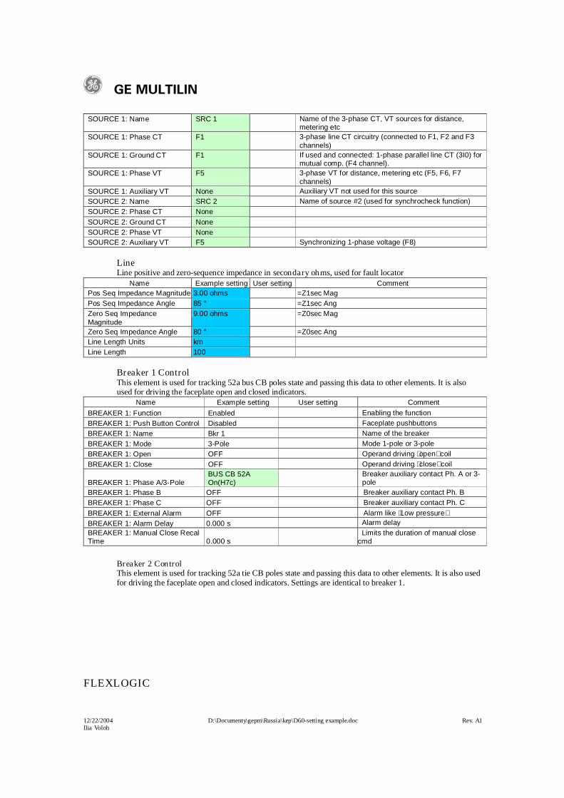
VT: VTpri=161000/3V, VTsec=115/3V, VTR= VTpri/ VTsec=161000/115=1400CT: CTpri=600, CTsec=5A. CTR= CTpri/ CTsec=600/5=120 Protected Line:
Length: L=100 kmLine impedance: Z1pri=3585, Z0pri=10580
8531400
1203511
*VTR
CTR*priZsecZ
8091400
12010500
*VTR
CTR*priZsecZ
Normal system impedance of the source behind relay: Sb=60,
1451400
12060.
*VTR
CTR*ZbsecZb
Normal system impedance of the source in front of the relay: Sf=70,
61400
1200 *VTR
CTR*ZfsecZf
Minimum system impedance of the source behind relay: Sb_min=80Minimum system impedance of the source in front of the relay: Sf_min=90Minimum SLG end of the line fault current with infeed from behind source only is:
A)**(*
*
)priZpriZ*min_Sb*(*
*VTprimin_IFgr 672
1053528033
3161000
01233
31
Minimum SLG end of the line fault current flowing in the relay with infeed from both sources:
Amin_SfpriZmin_Sb
min_Sf*
min_SfpriZmin_Sbmin_Sf*)priZmin_Sb(
min_SfpriZmin_Sbmin_Sf*)priZmin_Sb(
**
*VTprimin_IFgr 255
1
00
11
23
32
Minimum Three-phase end of the line fault current flowing in the relay with infeed from both sources:
~ ~Zb ZfZ1, Z0
g GE MULTILIN
12/22/2004 D:\Documenty\gepm\Russia\kep\D60-setting example.doc Rev. A1Ilia Voloh
Amin_SfprimZmin_Sb
min_Sf*
min_SfprimZmin_Sbmin_Sf*)primZmin_Sb(
*
VTprimmin_phIF 885
111
33
Minimum phase-to-phase end of the line fault current flowing in the relay with infeed from both sources:
Amin*_phIF
min_phIF 7672
332
Maximum load current allowed is: IL = 600A =1.0pu, load impedance is
3.13IL*3
CTRsec*VTsecZL
PRODUCT SETUP
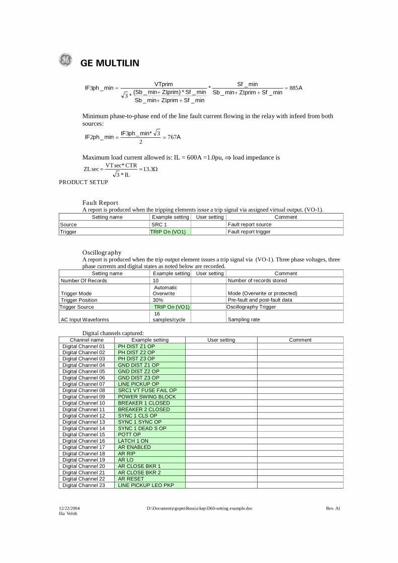
Fault Report A report is produced when the tripping elements issue a trip signal via assigned virtual output. (VO-1).
Setting name Example setting User setting CommentFault Report Source SRC 1 Fault report sourceFault Report Trigger TRIP On (VO1) Fault report trigger
OscillographyA report is produced when the trip output element issues a trip signal via (VO-1). Three phase voltages, three phase currents and digital states as noted below are recorded.
Setting name Example setting User setting Comment Number Of Records 10 Number of records stored
Trigger Mode Automatic Overwrite Mode (Overwrite or protected)
Trigger Position 30% Pre-fault and post-fault dataTrigger Source TRIP On (VO1) Oscillography Trigger
AC Input Waveforms 16 samples/cycle Sampling rate
Digital channels captured:Channel name Example setting User setting Comment
Digital Channel 01 PH DIST Z1 OPDigital Channel 02 PH DIST Z2 OPDigital Channel 03 PH DIST Z3 OPDigital Channel 04 GND DIST Z1 OPDigital Channel 05 GND DIST Z2 OPDigital Channel 06 GND DIST Z3 OPDigital Channel 07 LINE PICKUP OPDigital Channel 08 SRC1 VT FUSE FAIL OPDigital Channel 09 POWER SWING BLOCKDigital Channel 10 BREAKER 1 CLOSEDDigital Channel 11 BREAKER 2 CLOSEDDigital Channel 12 SYNC 1 CLS OPDigital Channel 13 SYNC 1 SYNC OPDigital Channel 14 SYNC 1 DEAD S OPDigital Channel 15 POTT OPDigital Channel 16 LATCH 1 ONDigital Channel 17 AR ENABLEDDigital Channel 18 AR RIPDigital Channel 19 AR LODigital Channel 20 AR CLOSE BKR 1Digital Channel 21 AR CLOSE BKR 2Digital Channel 22 AR RESETDigital Channel 23 LINE PICKUP LEO PKP
g GE MULTILIN
12/22/2004 D:\Documenty\gepm\Russia\kep\D60-setting example.doc Rev. A1Ilia Voloh
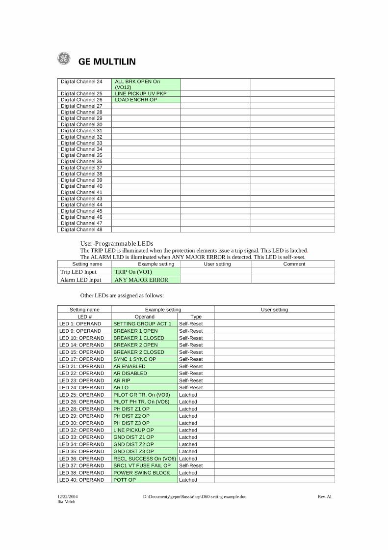
Digital Channel 24 ALL BRK OPEN On (VO12)
Digital Channel 25 LINE PICKUP UV PKPDigital Channel 26 LOAD ENCHR OPDigital Channel 27Digital Channel 28Digital Channel 29Digital Channel 30Digital Channel 31Digital Channel 32Digital Channel 33Digital Channel 34Digital Channel 35Digital Channel 36Digital Channel 37Digital Channel 38Digital Channel 39Digital Channel 40Digital Channel 41Digital Channel 43Digital Channel 44Digital Channel 45Digital Channel 46Digital Channel 47Digital Channel 48
User-Programmable LEDs The TRIP LED is illuminated when the protection elements issue a trip signal. This LED is latched.The ALARM LED is illuminated when ANY MAJOR ERROR is detected. This LED is self-reset.
Setting name Example setting User setting Comment
Trip LED Input TRIP On (VO1)Alarm LED Input ANY MAJOR ERROR
Other LEDs are assigned as follows:
Setting name Example setting User settingLED # Operand Type
LED 1: OPERAND SETTING GROUP ACT 1 Self-Reset LED 9: OPERAND BREAKER 1 OPEN Self-Reset LED 10: OPERAND BREAKER 1 CLOSED Self-Reset LED 14: OPERAND BREAKER 2 OPEN Self-Reset LED 15: OPERAND BREAKER 2 CLOSED Self-Reset LED 17: OPERAND SYNC 1 SYNC OP Self-Reset LED 21: OPERAND AR ENABLED Self-Reset LED 22: OPERAND AR DISABLED Self-Reset LED 23: OPERAND AR RIP Self-Reset LED 24: OPERAND AR LO Self-Reset LED 25: OPERAND PILOT GR TR. On (VO9) Latched LED 26: OPERAND PILOT PH TR. On (VO8) Latched LED 28: OPERAND PH DIST Z1 OP Latched LED 29: OPERAND PH DIST Z2 OP LatchedLED 30: OPERAND PH DIST Z3 OP Latched
LED 32: OPERAND LINE PICKUP OP Latched LED 33: OPERAND GND DIST Z1 OP Latched LED 34: OPERAND GND DIST Z2 OP Latched LED 35: OPERAND GND DIST Z3 OP Latched LED 36: OPERAND RECL SUCCESS On (VO6) Latched LED 37: OPERAND SRC1 VT FUSE FAIL OP Self-Reset LED 38: OPERAND POWER SWING BLOCK Latched LED 40: OPERAND POTT OP Latched
g GE MULTILIN
12/22/2004 D:\Documenty\gepm\Russia\kep\D60-setting example.doc Rev. A1Ilia Voloh
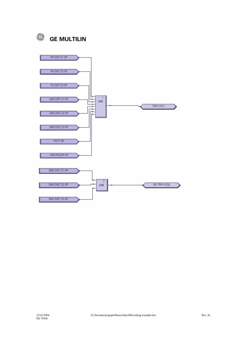
GND DIST Z1 OP
GND DIST Z2 OP
GND DIST Z3 OP
OROROR2
GR TRIP (VO2)
PH DIST Z1 OP
PH DIST Z2 OP
PH DIST Z3 OP
GND DIST Z1 OP
GND DIST Z2 OP
GND DIST Z3 OP
POTT OP
LINE PICKUP OP
OROROR1
TRIP (VO1)
g GE MULTILIN
12/22/2004 D:\Documenty\gepm\Russia\kep\D60-setting example.doc Rev. A1Ilia Voloh
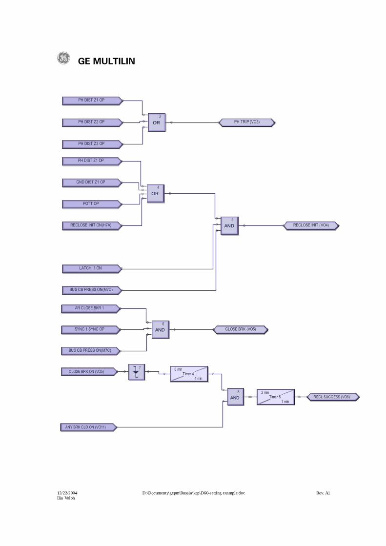
PH DIST Z1 OP
PH DIST Z2 OP
PH DIST Z3 OP
OROROR3
PH TRIP (VO3)
PH DIST Z1 OP
GND DIST Z1 OP
POTT OP
RECLOSE INIT ON(H7A)
OROROR4
LATCH 1 ON
BUS CB PRESS ON(M7C)
ANDANDAND5
RECLOSE INIT (VO4)
AR CLOSE BKR 1
SYNC 1 SYNC OP
BUS CB PRESS ON(M7C)
ANDANDAND6
CLOSE BRK (VO5)
CLOSE BRK ON (VO5)7 0 min
Timer 44 min
ANY BRK CLD ON (VO11)
ANDANDAND8 2 min
Timer 51 min
RECL SUCCESS (VO6)
g GE MULTILIN
12/22/2004 D:\Documenty\gepm\Russia\kep\D60-setting example.doc Rev. A1Ilia Voloh
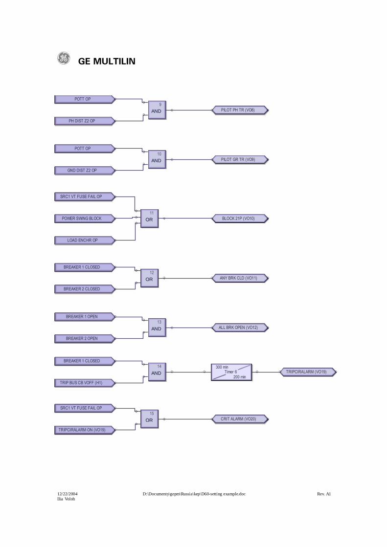
POTT OP
PH DIST Z2 OP
ANDANDAND9
PILOT PH TR (VO8)
POTT OP
GND DIST Z2 OP
ANDANDAND10
PILOT GR TR (VO9)
SRC1 VT FUSE FAIL OP
POWER SWING BLOCK
LOAD ENCHR OP
OROROR11
BLOCK 21P (VO10)
BREAKER 1 CLOSED
BREAKER 2 CLOSED
OROROR12
ANY BRK CLD (VO11)
BREAKER 1 OPEN
BREAKER 2 OPEN
ANDANDAND13
ALL BRK OPEN (VO12)
BREAKER 1 CLOSED
TRIP BUS CB VOFF (H1)
ANDANDAND14 300 min
Timer 6200 min
TRIPCIRALARM (VO19)
SRC1 VT FUSE FAIL OP
TRIPCIRALARM ON (VO19)
OROROR15
CRIT ALARM (VO20)

g GE MULTILIN
12/22/2004 D:\Documenty\gepm\Russia\kep\D60-setting example.doc Rev. A1Ilia Voloh
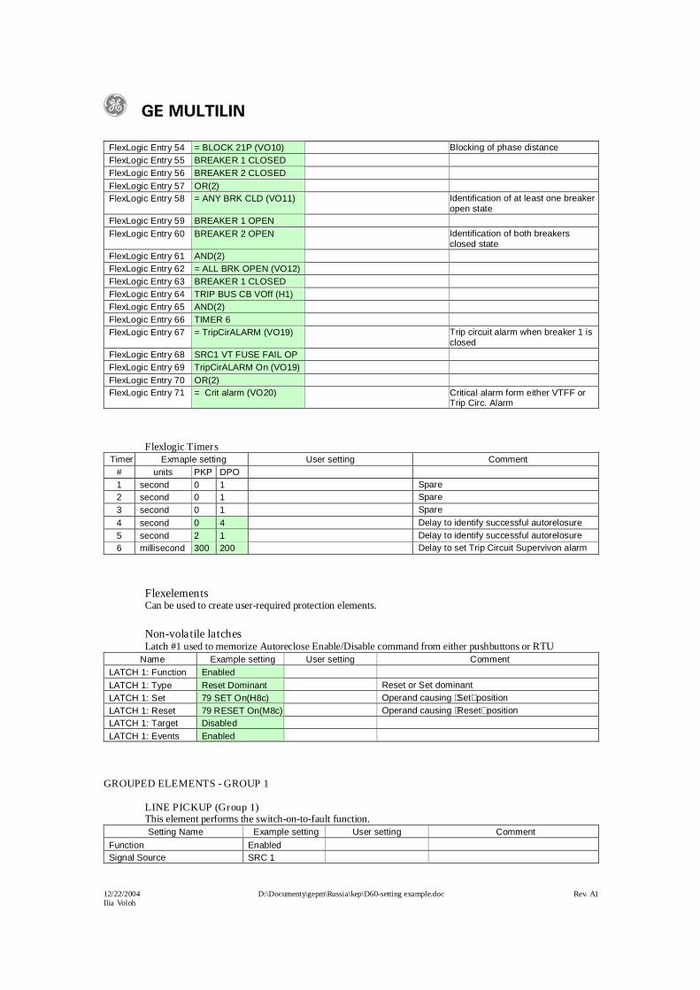
Entry Example setting User setting CommentFlexLogic Entry 1 PH DIST Z1 OP Function assigned to cause a tripFlexLogic Entry 2 PH DIST Z2 OP Function assigned to cause a tripFlexLogic Entry 3 PH DIST Z3 OP Function assigned to cause a tripFlexLogic Entry 4 GND DIST Z1 OP Function assigned to cause a tripFlexLogic Entry 5 GND DIST Z2 OP Function assigned to cause a tripFlexLogic Entry 6 GND DIST Z3 OP Function assigned to cause a tripFlexLogic Entry 7 POTT OP Function assigned to cause a tripFlexLogic Entry 8 LINE PICKUP OP Function assigned to cause a tripFlexLogic Entry 9 OR(8)FlexLogic Entry 10 = TRIP (VO1) Tripping gate assigned to Trip
contacts FlexLogic Entry 11 GND DIST Z1 OPFlexLogic Entry 12 GND DIST Z2 OPFlexLogic Entry 13 GND DIST Z3 OPFlexLogic Entry 14 OR(3)FlexLogic Entry 15 = GR TRIP (VO2) Any Ground Distance zone
operationFlexLogic Entry 16 PH DIST Z1 OPFlexLogic Entry 17 PH DIST Z2 OPFlexLogic Entry 18 PH DIST Z3 OPFlexLogic Entry 19 OR(3)FlexLogic Entry 20 = PH TRIP (VO3) Any Phase Distance zone operationFlexLogic Entry 21 PH DIST Z1 OPFlexLogic Entry 22 GND DIST Z1 OPFlexLogic Entry 23 POTT OPFlexLogic Entry 24 RECLOSE INIT On(H7a)FlexLogic Entry 25 OR(4)FlexLogic Entry 26 LATCH 1 ONFlexLogic Entry 27 BUS CB PRESS On(M7c)FlexLogic Entry 28 AND(3)FlexLogic Entry 29 = RECLOSE INIT (VO4) Gate assigned to initiate recloseFlexLogic Entry 30 AR CLOSE BKR 1FlexLogic Entry 31 SYNC 1 SYNC OPFlexLogic Entry 32 BUS CB PRESS On(M7c)FlexLogic Entry 33 AND(3)FlexLogic Entry 34 = CLOSE BRK (VO5) Breaker close command,
autoreclose with synchcheckFlexLogic Entry 35 CLOSE BRK On (VO5)FlexLogic Entry 36 NEGATIVE ONE SHOTFlexLogic Entry 37 TIMER 4FlexLogic Entry 38 ANY BRK CLD On (VO11) At least one breaker closedFlexLogic Entry 39 AND(2)FlexLogic Entry 40 TIMER 5FlexLogic Entry 41 = RECL SUCCESS (VO6) Identification of successful
reclosureFlexLogic Entry 42 POTT OPFlexLogic Entry 43 PH DIST Z2 OPFlexLogic Entry 44 AND(2)FlexLogic Entry 45 = PILOT PH TR (VO8) Identification of pilot phase tripFlexLogic Entry 46 POTT OPFlexLogic Entry 47 GND DIST Z2 OPFlexLogic Entry 48 AND(2)FlexLogic Entry 49 = PILOT GR TR (VO9) Identification of pilot ground tripFlexLogic Entry 50 SRC1 VT FUSE FAIL OPFlexLogic Entry 51 POWER SWING BLOCKFlexLogic Entry 52 LOAD ENCHR OPFlexLogic Entry 53 OR(3)
g GE MULTILIN
12/22/2004 D:\Documenty\gepm\Russia\kep\D60-setting example.doc Rev. A1Ilia Voloh
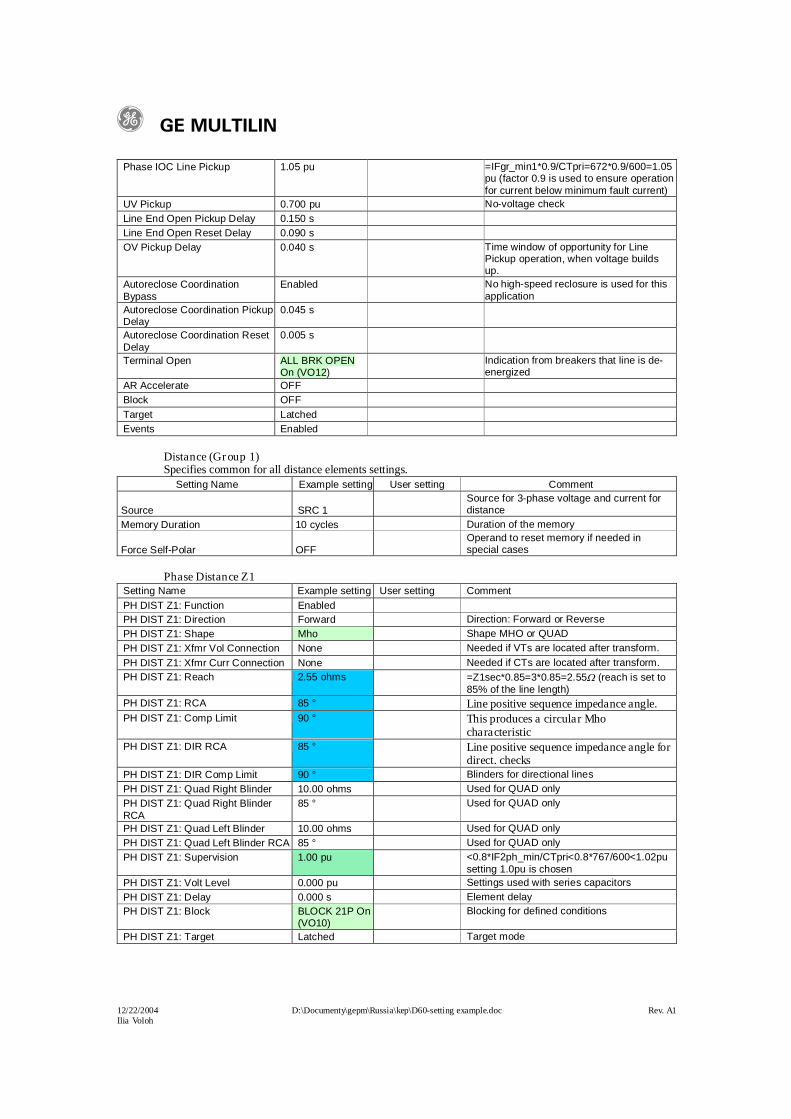
Phase IOC Line Pickup 1.05 pu =IFgr_min1*0.9/CTpri=672*0.9/600=1.05pu (factor 0.9 is used to ensure operation for current below minimum fault current)
UV Pickup 0.700 pu No-voltage checkLine End Open Pickup Delay 0.150 sLine End Open Reset Delay 0.090 sOV Pickup Delay 0.040 s Time window of opportunity for Line
Pickup operation, when voltage builds up.
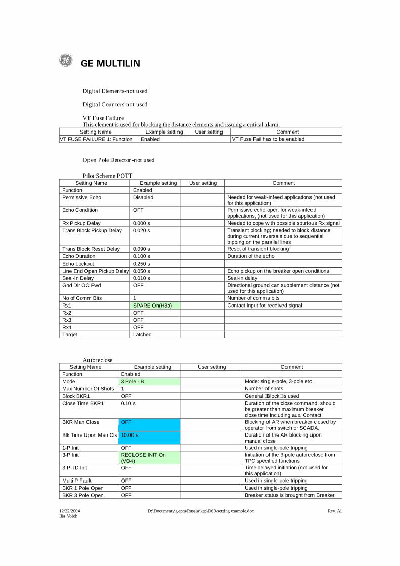
Autoreclose Coordination Bypass
Enabled No high-speed reclosure is used for this application
Autoreclose Coordination Pickup Delay
0.045 s
Autoreclose Coordination Reset Delay
0.005 s
Terminal Open ALL BRK OPEN On (VO12)
Indication from breakers that line is de-energized
AR Accelerate OFFBlock OFFTarget LatchedEvents Enabled
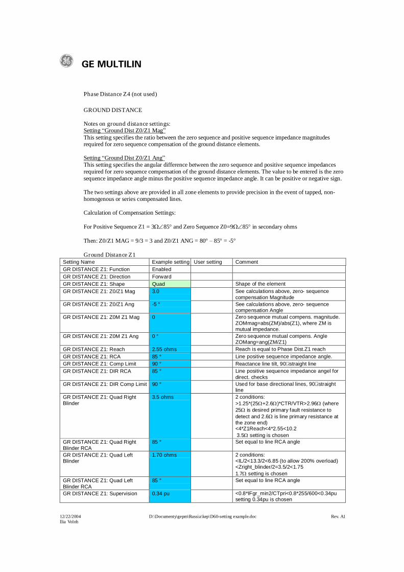
Distance (Group 1)Specifies common for all distance elements settings.
Setting Name Example setting User setting Comment
Source SRC 1Source for 3-phase voltage and current for distance
Memory Duration 10 cycles Duration of the memory
Force Self-Polar OFFOperand to reset memory if needed in special cases
Phase Distance Z1 Setting Name Example setting User setting CommentPH DIST Z1: Function EnabledPH DIST Z1: Direction Forward Direction: Forward or ReversePH DIST Z1: Shape Mho Shape MHO or QUADPH DIST Z1: Xfmr Vol Connection None Needed if VTs are located after transform. PH DIST Z1: Xfmr Curr Connection None Needed if CTs are located after transform.PH DIST Z1: Reach 2.55 ohms =Z1sec*0.85=3*0.85=2.55 (reach is set to
85% of the line length)PH DIST Z1: RCA 85 ° Line positive sequence impedance angle.PH DIST Z1: Comp Limit 90 ° This produces a circular Mho
characteristicPH DIST Z1: DIR RCA 85 ° Line positive sequence impedance angle for
direct. checksPH DIST Z1: DIR Comp Limit 90 ° Blinders for directional linesPH DIST Z1: Quad Right Blinder 10.00 ohms Used for QUAD onlyPH DIST Z1: Quad Right Blinder RCA
85 ° Used for QUAD only
PH DIST Z1: Quad Left Blinder 10.00 ohms Used for QUAD onlyPH DIST Z1: Quad Left Blinder RCA 85 ° Used for QUAD onlyPH DIST Z1: Supervision 1.00 pu <0.8*IF2ph_min/CTpri<0.8*767/600<1.02pu
setting 1.0pu is chosenPH DIST Z1: Volt Level 0.000 pu Settings used with series capacitorsPH DIST Z1: Delay 0.000 s Element delayPH DIST Z1: Block BLOCK 21P On
(VO10)Blocking for defined conditions
PH DIST Z1: Target Latched Target mode
g GE MULTILIN
12/22/2004 D:\Documenty\gepm\Russia\kep\D60-setting example.doc Rev. A1Ilia Voloh
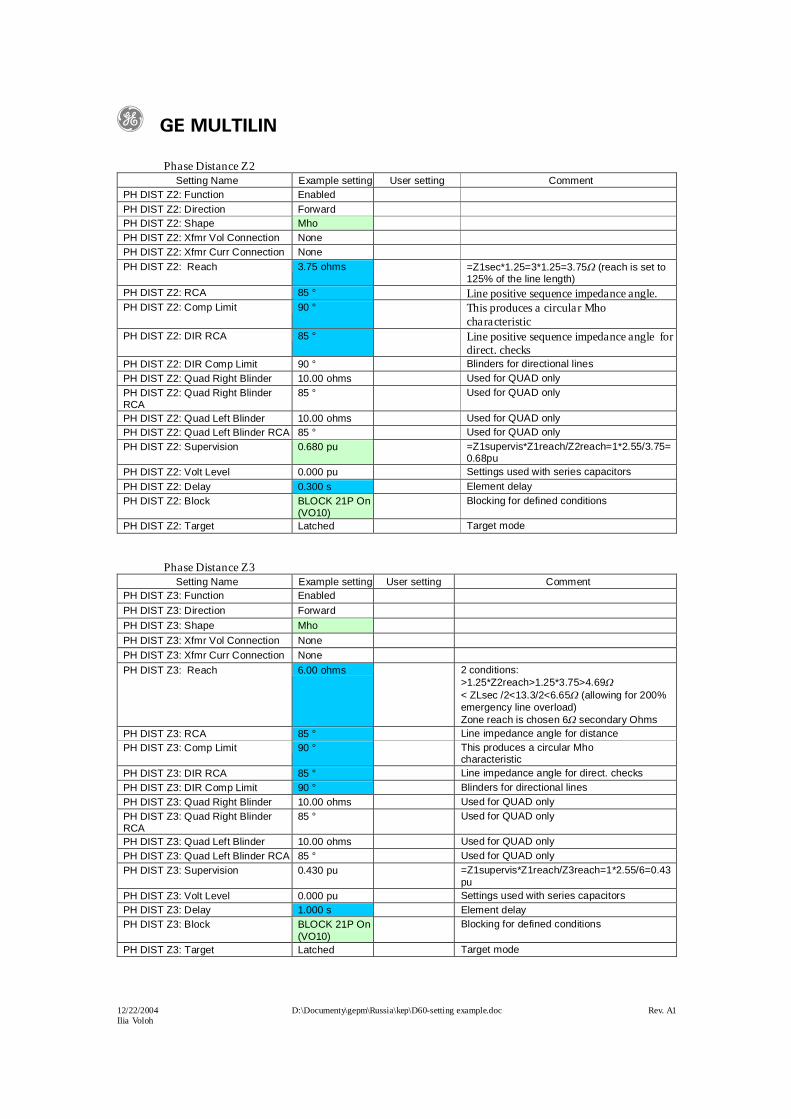
Phase Distance Z2Setting Name Example setting User setting Comment
PH DIST Z2: Function EnabledPH DIST Z2: Direction ForwardPH DIST Z2: Shape MhoPH DIST Z2: Xfmr Vol Connection NonePH DIST Z2: Xfmr Curr Connection NonePH DIST Z2: Reach 3.75 ohms =Z1sec*1.25=3*1.25=3.75 (reach is set to
125% of the line length)PH DIST Z2: RCA 85 ° Line positive sequence impedance angle.PH DIST Z2: Comp Limit 90 ° This produces a circular Mho
characteristicPH DIST Z2: DIR RCA 85 ° Line positive sequence impedance angle for
direct. checksPH DIST Z2: DIR Comp Limit 90 ° Blinders for directional linesPH DIST Z2: Quad Right Blinder 10.00 ohms Used for QUAD onlyPH DIST Z2: Quad Right Blinder RCA
85 ° Used for QUAD only
PH DIST Z2: Quad Left Blinder 10.00 ohms Used for QUAD onlyPH DIST Z2: Quad Left Blinder RCA 85 ° Used for QUAD onlyPH DIST Z2: Supervision 0.680 pu =Z1supervis*Z1reach/Z2reach=1*2.55/3.75=
0.68puPH DIST Z2: Volt Level 0.000 pu Settings used with series capacitorsPH DIST Z2: Delay 0.300 s Element delayPH DIST Z2: Block BLOCK 21P On
(VO10)Blocking for defined conditions
PH DIST Z2: Target Latched Target mode
Phase Distance Z3Setting Name Example setting User setting Comment
PH DIST Z3: Function EnabledPH DIST Z3: Direction ForwardPH DIST Z3: Shape MhoPH DIST Z3: Xfmr Vol Connection NonePH DIST Z3: Xfmr Curr Connection NonePH DIST Z3: Reach 6.00 ohms 2 conditions:
>1.25*Z2reach>1.25*3.75>4.69< ZLsec /2<13.3/2<6.65 (allowing for 200% emergency line overload)Zone reach is chosen 6 secondary Ohms
PH DIST Z3: RCA 85 ° Line impedance angle for distancePH DIST Z3: Comp Limit 90 ° This produces a circular Mho
characteristicPH DIST Z3: DIR RCA 85 ° Line impedance angle for direct. checksPH DIST Z3: DIR Comp Limit 90 ° Blinders for directional linesPH DIST Z3: Quad Right Blinder 10.00 ohms Used for QUAD onlyPH DIST Z3: Quad Right Blinder RCA
85 ° Used for QUAD only
PH DIST Z3: Quad Left Blinder 10.00 ohms Used for QUAD onlyPH DIST Z3: Quad Left Blinder RCA 85 ° Used for QUAD onlyPH DIST Z3: Supervision 0.430 pu =Z1supervis*Z1reach/Z3reach=1*2.55/6=0.43
puPH DIST Z3: Volt Level 0.000 pu Settings used with series capacitorsPH DIST Z3: Delay 1.000 s Element delayPH DIST Z3: Block BLOCK 21P On
(VO10)Blocking for defined conditions
PH DIST Z3: Target Latched Target mode
g GE MULTILIN
12/22/2004 D:\Documenty\gepm\Russia\kep\D60-setting example.doc Rev. A1Ilia Voloh
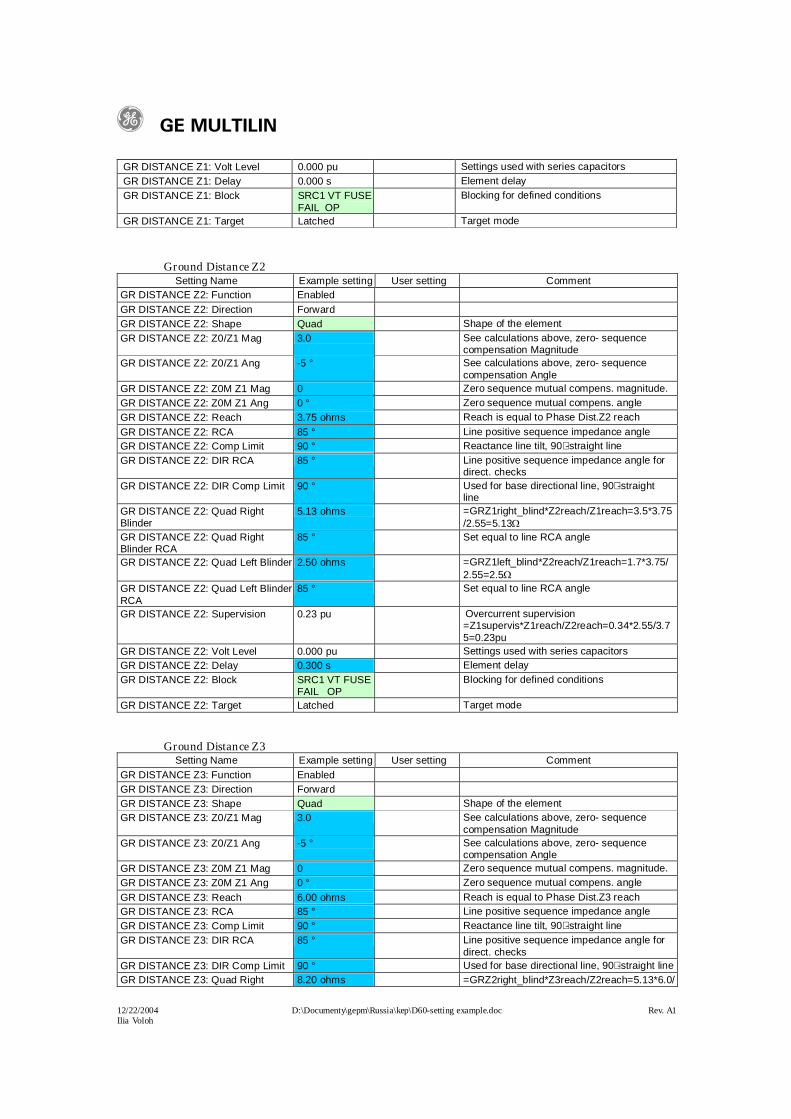
Blinder 3.75=8.2GR DISTANCE Z3: Quad Right Blinder RCA
85 ° Set equal to line RCA angle
GR DISTANCE Z3: Quad Left Blinder 4.00 ohms =GRZ2left_blind*Z3reach/Z2reach=2.5*6.0/3.75=4.0
GR DISTANCE Z3: Quad Left Blinder RCA
85 ° Set equal to line RCA angle
GR DISTANCE Z3: Supervision 0.15 pu Overcurrent supervision=Z1supervis*Z1reach/Z2reach=0.34*2.55/6=0.15pu
GR DISTANCE Z3: Volt Level 0.000 pu Settings used with series capacitorsGR DISTANCE Z3: Delay 1.000 s Element delayGR DISTANCE Z3: Block SRC1 VT FUSE
FAIL OPBlocking for defined conditions
GR DISTANCE Z3: Target Latched Target mode
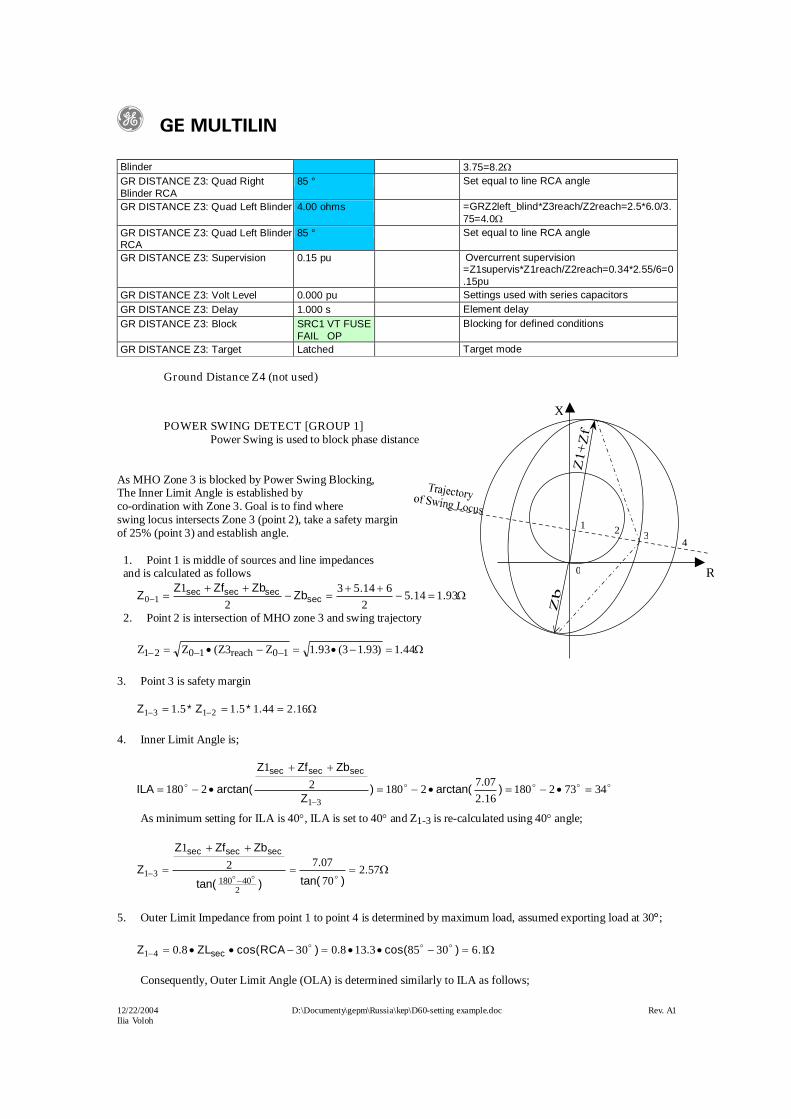
Ground Distance Z4 (not used)
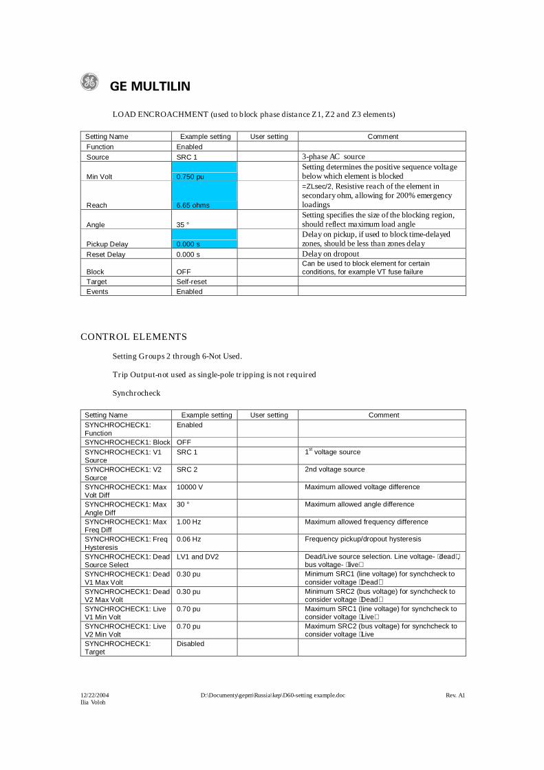
POWER SWING DETECT [GROUP 1]Power Swing is used to block phase distance
As MHO Zone 3 is blocked by Power Swing Blocking,The Inner Limit Angle is established by co-ordination with Zone 3. Goal is to find where swing locus intersects Zone 3 (point 2), take a safety marginof 25% (point 3) and establish angle.
1. Point 1 is middle of sources and line impedances and is calculated as follows
9311452
614532
110 ..
.Zb
ZbZfZZ sec
secsecsec
2. Point 2 is intersection of MHO zone 3 and swing trajectory
44.1)93.13(93.1Z3Z(ZZ 10reach1021
3. Point 3 is safety margin
1624415151 2131 ..*.Z*.Z
4. Inner Limit Angle is;
34732180162077
218021
218031
)..
arctan()Z
ZbZfZ
arctan(ILA
secsecsec
As minimum setting for ILA is 40, ILA is set to 40 and Z1-3 is re-calculated using 40 angle;
57270
07721
240180
31 .)tan(
.
)tan(
ZbZfZ
Z
secsecsec
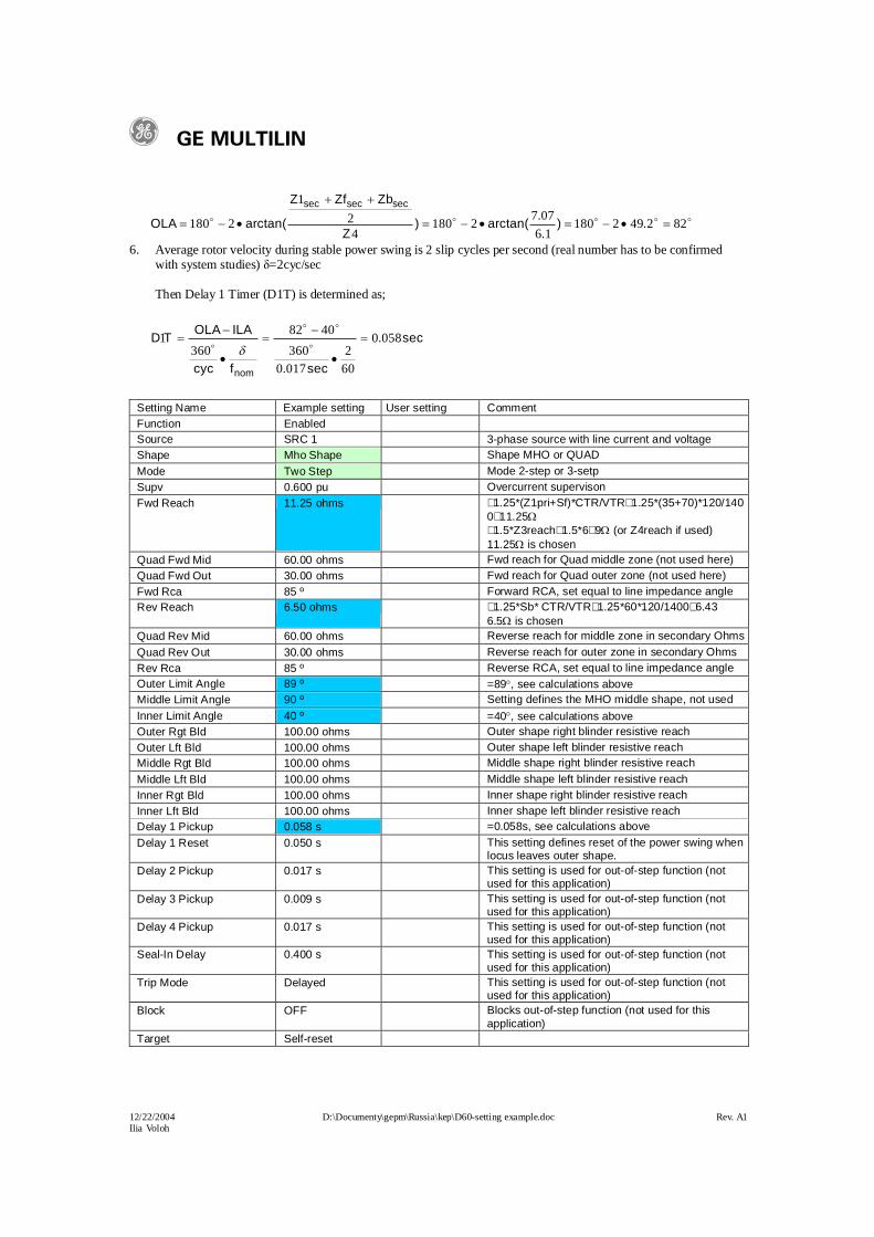
5. Outer Limit Impedance from point 1 to point 4 is determined by maximum load, assumed exporting load at 30;
16308531380308041 .)cos(..)RCAcos(ZL.Z sec
Consequently, Outer Limit Angle (OLA) is determined similarly to ILA as follows;
2 3
0
1
4
R
X
g GE MULTILIN
12/22/2004 D:\Documenty\gepm\Russia\kep\D60-setting example.doc Rev. A1Ilia Voloh
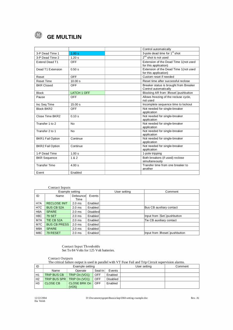
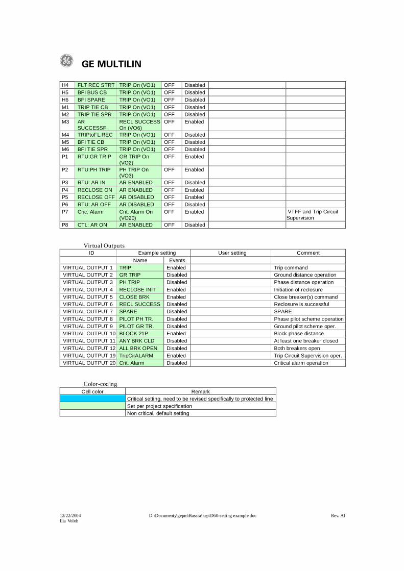
H4 FLT REC STRT TRIP On (VO1) OFF Disabled H5 BFI BUS CB TRIP On (VO1) OFF Disabled H6 BFI SPARE TRIP On (VO1) OFF Disabled M1 TRIP TIE CB TRIP On (VO1) OFF Disabled M2 TRIP TIE SPR TRIP On (VO1) OFF Disabled M3 AR
SUCCESSF.RECL SUCCESS On (VO6)
OFF Enabled
M4 TRIPtoFL.REC TRIP On (VO1) OFF Disabled M5 BFI TIE CB TRIP On (VO1) OFF Disabled M6 BFI TIE SPR TRIP On (VO1) OFF Disabled P1 RTU:GR TRIP GR TRIP On
(VO2)OFF Enabled
P2 RTU:PH TRIP PH TRIP On (VO3)
OFF Enabled
P3 RTU: AR IN AR ENABLED OFF Disabled P4 RECLOSE ON AR ENABLED OFF Enabled P5 RECLOSE OFF AR DISABLED OFF Enabled P6 RTU: AR OFF AR DISABLED OFF Disabled P7 Cric. Alarm Crit. Alarm On
(VO20)OFF Enabled VTFF and Trip Circuit
Supervision P8 CTL: AR ON AR ENABLED OFF Disabled
Virtual OutputsID Example setting User setting Comment
Name EventsVIRTUAL OUTPUT 1 TRIP Enabled Trip command VIRTUAL OUTPUT 2 GR TRIP Disabled Ground distance operationVIRTUAL OUTPUT 3 PH TRIP Disabled Phase distance operationVIRTUAL OUTPUT 4 RECLOSE INIT Enabled Initiation of reclosureVIRTUAL OUTPUT 5 CLOSE BRK Enabled Close breaker(s) command VIRTUAL OUTPUT 6 RECL SUCCESS Disabled Reclosure is successfulVIRTUAL OUTPUT 7 SPARE Disabled SPAREVIRTUAL OUTPUT 8 PILOT PH TR. Disabled Phase pilot scheme operation VIRTUAL OUTPUT 9 PILOT GR TR. Disabled Ground pilot scheme oper.VIRTUAL OUTPUT 10 BLOCK 21P Enabled Block phase distanceVIRTUAL OUTPUT 11 ANY BRK CLD Disabled At least one breaker closedVIRTUAL OUTPUT 12 ALL BRK OPEN Disabled Both breakers openVIRTUAL OUTPUT 19 TripCirALARM Enabled Trip Circuit Supervision oper.VIRTUAL OUTPUT 20 Crit. Alarm Disabled Critical alarm operation
Color-codingCell color Remark
Critical setting, need to be revised specifically to protected line Set per project specification Non critical, default setting
g GE MULTILIN
12/22/2004 D:\Documenty\gepm\Russia\kep\D60-setting example.doc Rev. A1Ilia Voloh