Embed Size (px)
Citation preview
GE Digital Energy
D20/D200
Installation and Operations Guide 994-0078 Version 2.00 Revision 9
GE Information
D20/D200 Installation and Operations Guide GE Digital Energy
994-0078-2.00-9 GE Information
ii
COPYRIGHT NOTICE
© 2007-2014, General Electric Canada. All rights reserved.
The Software Product described in this documentation may only be used in accordance with the applicable License Agreement. The Software Product and Associated Material are deemed to be “commercial computer software” and “commercial computer software documentation,” respectively, pursuant to DFAR Section 227.7202 and FAR Section 12.212, as applicable, and are delivered with Restricted Rights. Such restricted rights are those identified in the License Agreement, and as set forth in the “Restricted Rights Notice” contained in paragraph (g) (3) (Alternate III) of FAR 52.227-14, Rights in Data-General, including Alternate III (June 1987).
If applicable, any use, modification, reproduction release, performance, display or disclosure of the Software Product and Associated Material by the U.S. Government shall be governed solely by the terms of the License Agreement and shall be prohibited except to the extent expressly permitted by the terms of the License Agreement.
The information contained in this online publication is the exclusive property of General Electric Canada, except as otherwise indicated. You may view, copy and print documents and graphics incorporated in this online publication (the “Documents”) subject to the following: (1) the Documents may be used solely for personal, informational, non-commercial purposes; (2) the Documents may not be modified or altered in any way; and (3) General Electric Canada withholds permission for making the Documents or any portion thereof accessible via the internet. Except as expressly provided herein, you may not use, copy, print, display, reproduce, publish, license, post, transmit or distribute the Documents in whole or in part without the prior written permission of General Electric Canada. If applicable, any use, modification, reproduction, release, performance, display, or disclosure of the Software Product and Associated Material by the U.S. Government shall be governed solely by the terms of the License Agreement and shall be prohibited except to the extent expressly permitted by the terms of the License Agreement.
The information contained in this online publication is subject to change without notice. The software described in this online publication is supplied under license and may be used or copied only in accordance with the terms of such license.
TRADEMARK NOTICES
GE and are trademarks and service marks of General Electric Canada.
* Trademarks of General Electric Canada.
Microsoft® and Windows® are claimed as a registered trademark by Microsoft Corporation, which is not affiliated with GE.
Microsoft Windows™ is claimed as a trademark by Microsoft Corporation, which is not affiliated with GE.
Motorola® is claimed as a registered trademark by Motorola Inc., which is not affiliated with GE.
Schroff® is claimed as a registered trademark by Schroff GmbH, which is not affiliated with GE.
Tadiran® is claimed as a registered trademark by Tadiran Telecommunications Inc., which is not affiliated with GE.
Telenetics® is claimed as a registered trademark by Telenetics Corporation, which is not affiliated with GE.
Other company or product names mentioned in this document may be trademarks or registered trademarks of their respective companies. Other company or product names mentioned in this document may be trademarks or registered trademarks of their respective companies.
GE Digital Energy D20/D200 Installation and Operations Guide
GE Information 994-0078-2.00-9 1
Contents Sections Use this D20/D200 Installation and Operations Guide for installing, operating and
maintaining your D20 or D200. The guide is divided into the following sections.
Topic See Page
Section 1: Installation and Commissioning.
Product Support and Safety 2
About this Guide 10
Getting Started: Required Steps 11
Familiarization 13
Connections and Configuration 42
Power-up and Test 89
Section 2: Operation and Maintenance.
D20/D200 Software Configuration 99
Operation 115
Servicing 118
Appendices
Appendix A: Product Combinations 122
Appendix B: 68K Monitor Commands 127
D20/D200 Installation and Operations Guide GE Digital Energy
994-0078-2.00-9 GE Information
2
Product Support and Safety Getting help If you need help with any aspect of your GE Digital Energy product, you have a few
options.
Search Technical Support
The GE Energy Web site provides fast access to technical information, such as manuals, release notes and knowledge base topics. Visit us on the Web at:
http://www.gedigitalenergy.com/
Contact Customer Support
The GE Energy Customer Service Center is open 24 hours a day, seven days a week for you to talk directly to a GE representative.
In the U.S. and Canada, call toll-free: 1 877 547 8630
International customers, please call: +1 905 927 7070
Or e-mail to [email protected]
Have the following information ready to give to Customer Service:
• Ship to address (the address that the product is to be returned to)
• Bill to address (the address that the invoice is to be sent to)
• Contact name
• Contact phone number
• Contact fax number
• Contact e-mail address
• Product number / serial number
• Description of problem The Customer Service centre will provide you with a case number for your reference.
Product returns
Before you return a product, please contact the GE Digital Energy Customer Service Center to obtain a Return Merchandise Authorization number and complete instructions for return shipments.
A Return Merchandise Authorization (RMA) number must accompany all equipment being returned for repair, servicing, or for any other reason.
Note: Product returns will not be accepted without a Return Merchandise Authorization number.
!
Trying to resolve problems using methods that are not recommended by GE Energy may result in damage or injury to persons and property.
GE Digital Energy D20/D200 Installation and Operations Guide
GE Information 994-0078-2.00-9 3
Product Support and Safety, continued
Warranty GE Energy warrants each D20 and D200 product to be free of defects in material and workmanship under normal use and service for a period of 18 months from the date of shipment from the factory.
In the event of a failure covered by warranty, GE Energy will undertake to repair or replace the unit without charge, providing that the warrantor has determined that it is defective.
Warranty shall not apply to any unit which has been subject to:
• Misuse • Negligence • Accident • Incorrect installation • Use of this product in a manner not specified by GE Energy in this Guide. • Alterations by anyone other than GE Energy, or an authorized representative. GE Energy is not liable for special, indirect or consequential damages, or for loss of profit or expenses sustained as a result of a product malfunction, incorrect application or adjustment.
Note The above terms are subject to change at any time, or as stipulated in contractual agreements.
Safety Precautions
Follow all safety precautions and instructions in this manual:
• Only qualified personnel should work on the D20/D200. Maintenance personnel should be familiar with hazards associated with electrical equipment.
• All AC voltage and current terminals are protected from accidental contact by mechanical safety shields. The D20/D200 is designed so that field wiring does not have to be touched or disconnected when removing field-replaceable printed circuit boards (PCBs).
• All components within the D20/D200 are susceptible to damage from electrostatic discharge. Observe standard ESD precautions.

D20/D200 Installation and Operations Guide GE Digital Energy
994-0078-2.00-9 GE Information
4
Product Support and Safety, continued
!
Hazardous Voltages
Hazardous Voltages can cause shock, burns or death.
• Due to the common bus architecture of D20 I/O peripherals, an energized condition may exist due to induced voltage or unrelated voltage backfeed even though specific parts of the circuit have been de-energized and presumed to be safe. Qualified personnel shall confirm the circuit is de-energized before commissioning or servicing the equipment
• Disconnect and lockout all power sources before servicing and removing components.
• Short all current transformer primaries before servicing. • The D20/D200 is designed to allow some components to be hot-swapped: they
can be safely removed and re-installed without powering down the unit: − Peripherals − Connectors under plastic covers carry hazardous voltages. Removal of plastic
cover will expose hazardous voltages.
Warning Symbols !
Caution (refer to accompanying documentation)
Caution Risk of electric shock
Earth/Ground Terminal
Protective Ground Terminal
Power Supply Off (Stand-by Mode)
Power Supply On
Direct Current
Alternating Current
GE Digital Energy D20/D200 Installation and Operations Guide
GE Information 994-0078-2.00-9 5
Product Support and Safety, continued
Operating Environment
• The D20/D200’s enclosure is intended for indoor use primarily to provide protection against accidental contact with the enclosed modules and voltages. Do not place the product in environments where unusual conditions exist (windblown dust and dirt, liquids, etc.) without a secondary protective enclosure.
• For proper fire protection, the D20/D200 must be installed in an enclosure that includes a metal floor with no openings.
• Never operate the D20/D200 in the field with any blanking panels removed. Operation with the front panel open may alter product performance specifications, and allow component damage from debris entering the unit.
!
Protection during
Maintenance
Ensure that the D20/D200 is protected from falling debris during maintenance.
Small metallic particles (such as wire clippings) can fall through the ventilation holes on the top of the unit, possibly damaging or interfering with the safe and reliable operation of the D20/D200.
If you cover the unit for maintenance, remove cover before operating to provide adequate cooling airflow.
Operation in Residential Areas
The D20/D200 generates radio frequency energy. If it is not operated and used in accordance with the instructions provided in this guide, it may cause harmful interference to radio communications in a residential area. Users are required to correct interference at their own expense.
!
Rack Spacing for free airflow
When mounting multiple D20/D200s in a rack (or if mounting a D20/D200 in a rack with other equipment) verify that there is at least one rack unit (RU) space above and below the D20/D200 to allow for cooling airflow (1 RU = 1.75 inches).
!
WESMAINT Cable
Use only a standard PROMAINT cable (GE Energy part number 977-0048) when you are connecting to the D20ME or ME II’s front-panel WESMAINT connector. Use of any other cable may cause serious damage.
D20/D200 Installation and Operations Guide GE Digital Energy
994-0078-2.00-9 GE Information
6
Product Support and Safety, continued
Do’s and Don’ts
Follow these practices at all times:
1. Surge and noise suppression components used on the D20 and D200 are designed to conduct during transients to prevent nuisance operation or damage to internal components. To ensure shunting of transients from line to ground, the D20’s and D200’s earth ground stud must be connected to a low impedance ground using braided cable or heavy solid copper conductor (12 AWG recommended). When making ground connections, ensure that all surfaces that are used for grounding are free of dirt, residue and corrosion. A coating such as glyptol can be used to protect these connections from oxidation and dirt deposits.
2. Ensure that cable shields are grounded at either the D20 or D200 auxiliary ground stud or at the field equipment. Do not ground the shields at more than one point because a potential difference may exist between grounds causing ground loops and undesirable noise sources.
3. Ensure that all nuts and screws are properly tightened.
4. Always replace fuses with the same type and rating used by GE Energy. For fuse types and ratings, see “Servicing”, page 118.
5. When connecting to communications equipment such as modems or radios, always use appropriate surge protectors to protect the communication ports.
6. To prevent interference with communications, route all communication cables away from power-carrying cables.
7. Always fuse-protect field sources.
8. Always configure the jumpers in your D20 or D200 prior to connecting field I/O.
9. Follow all instructions in this guide as they are presented.
10. Do not operate the D20 or D200 if it has been dropped or damaged. Return it to GE Energy for inspections and repair.
11. The D20 and D200 power supplies use switching technology. For proper operation, the input voltage must be within specified limits prior to turning on the D20’s or D200’s power switch.
12. Do not apply voltages outside the range of the product specifications. Voltages outside the specified range may lead to premature product failure.
13. Do not modify the D20 or D200 without prior written authorization form GE Energy.
!
Protective Earth/Ground
Make sure the D20 or D200 is grounded using the protective ground stud.
Connection must be provided with separate green/yellow wire connected between the D20 or D200 and the protective earth system of the facility. Minimum 12 AWG is recommended.
GE Digital Energy D20/D200 Installation and Operations Guide
GE Information 994-0078-2.00-9 7
CE Mark Compliance Information Overview Individual products of the D20 and D200 automation product family are classified
according to EU Directive 2004/108/EC as subassemblies / finished appliances exclusively intended for an industrial assembly operation for incorporation into other apparatus. They are not apparatus in the sense of the EMC Directive.
To achieve CE mark compliance, the end user shall be responsible for ensuring the final system/installation conforms to all requirements of the European Union Electromagnetic Compatibility (EMC) and Low Voltage (LV) Directives. Products installed in secondary EMC grade protection metallic cabinets and following proper installation practices depicted in D20/D200 User Manual should meet CE mark requirements.
For information regarding current regulatory compliance status of your order, please contact your local sales representative or email us at [email protected].
Classification of D20/D200 Products from the EMC Directive Perspective
The D20 and D200 line of products are intelligent, industrial grade control devices targeted for automation and control of electrical substations. These products are designed as modular and scalable devices allowing the non-consumer end user to build a system of virtually any size and complexity. The number of options and configurations can be large; therefore, trained personnel must be involved in the design and integration of the final system. Refer to the explanatory note below.
Due to the inherent complexity and almost limitless variations of final systems, it is not possible for the manufacturer to guarantee compliance in the factory of individual D20/D200 modules in a final system, with the exception of pre-assembled RTU cabinets. Therefore, the end user shall be responsible for ensuring the final system/installation complies with all requirements of the EMC and LV Directives.
Radiated Emissions and Radiated Immunity Considerations
The D20 and D200 products have been designed and hardened to operate in the harsh industrial environment of electrical substations. When placed in service, the final system must conform to the objectives of the EMC Directive. To meet RF emissions and RF susceptibility according to CISPR 11 Class “A”, all D20 and D200 products must be installed in an EMC grade secondary metallic protective enclosure/cabinet. Additional EMC countermeasures may have to be applied depending on complexity and size of the system.
D20/D200 Installation and Operations Guide GE Digital Energy
994-0078-2.00-9 GE Information
8
CE Mark Compliance Information, continued
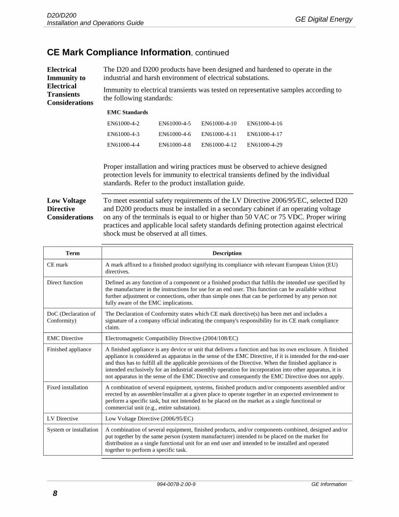
Electrical Immunity to Electrical Transients Considerations
The D20 and D200 products have been designed and hardened to operate in the industrial and harsh environment of electrical substations.
Immunity to electrical transients was tested on representative samples according to the following standards:
EMC Standards
EN61000-4-2 EN61000-4-5 EN61000-4-10 EN61000-4-16
EN61000-4-3 EN61000-4-6 EN61000-4-11 EN61000-4-17
EN61000-4-4 EN61000-4-8 EN61000-4-12 EN61000-4-29
Proper installation and wiring practices must be observed to achieve designed protection levels for immunity to electrical transients defined by the individual standards. Refer to the product installation guide.
Low Voltage Directive Considerations
To meet essential safety requirements of the LV Directive 2006/95/EC, selected D20 and D200 products must be installed in a secondary cabinet if an operating voltage on any of the terminals is equal to or higher than 50 VAC or 75 VDC. Proper wiring practices and applicable local safety standards defining protection against electrical shock must be observed at all times.
Term Description
CE mark A mark affixed to a finished product signifying its compliance with relevant European Union (EU) directives.
Direct function Defined as any function of a component or a finished product that fulfils the intended use specified by the manufacturer in the instructions for use for an end user. This function can be available without further adjustment or connections, other than simple ones that can be performed by any person not fully aware of the EMC implications.
DoC (Declaration of Conformity)
The Declaration of Conformity states which CE mark directive(s) has been met and includes a signature of a company official indicating the company's responsibility for its CE mark compliance claim.
EMC Directive Electromagnetic Compatibility Directive (2004/108/EC)
Finished appliance A finished appliance is any device or unit that delivers a function and has its own enclosure. A finished appliance is considered as apparatus in the sense of the EMC Directive, if it is intended for the end-user and thus has to fulfill all the applicable provisions of the Directive. When the finished appliance is intended exclusively for an industrial assembly operation for incorporation into other apparatus, it is not apparatus in the sense of the EMC Directive and consequently the EMC Directive does not apply.
Fixed installation A combination of several equipment, systems, finished products and/or components assembled and/or erected by an assembler/installer at a given place to operate together in an expected environment to perform a specific task, but not intended to be placed on the market as a single functional or commercial unit (e.g., entire substation).
LV Directive Low Voltage Directive (2006/95/EC)
System or installation A combination of several equipment, finished products, and/or components combined, designed and/or put together by the same person (system manufacturer) intended to be placed on the market for distribution as a single functional unit for an end user and intended to be installed and operated together to perform a specific task.
GE Digital Energy D20/D200 Installation and Operations Guide
GE Information 994-0078-2.00-9 9
CE Mark Compliance Information, continued
Explanatory Note
Consumer products (those sold to the public through retail) are designed to be installed by “untrained” personnel in the standard functional environment (e.g. PC enclosure), using only basic tools and a provided user’s manual. Additional adjustments to achieve EMC or LVD compliance are not required. Such products must bear the CE mark logo.
GE products are industrial grade products and are not available for sale through retail. These products require trained personnel for installation and may require additional adjustments, configuration or placement in a protective environment to meet requirements of EMC or LV Directives. Such products typically are not required to bear the CE mark logo.
Example
A clear distinction exists between a digital input card for a PC and the D20 digital input module. A PC digital input card is a consumer product, sold over the counter. An untrained person can install this card without specialized knowledge of EMC using only the supplied user ‘s manual. This PC digital input card should meet the intent of EMC & LV Directives when installed in a standard PC enclosure, for which it was designed and tested. Whereas, the D20 digital input module can be installed in numerous configurations and environments but by trained personnel.
D20/D200 Installation and Operations Guide GE Digital Energy
994-0078-2.00-9 GE Information
10
About this Guide The D20 and D200
The D20 and D200 remote terminal units belong to the same product family.
Using this Guide
Use this guide for installing, operating and maintaining your D20 or D200. The guide applies to both products. Separate sections are provided where there are significant differences between the two.
Many optional add-ons are available for customizing the D20 or D200 for specific operational requirements. This guide is restricted to a standard D20/D200 assembly with peripherals.
GE Digital Energy D20/D200 Installation and Operations Guide
GE Information 994-0078-2.00-9 11
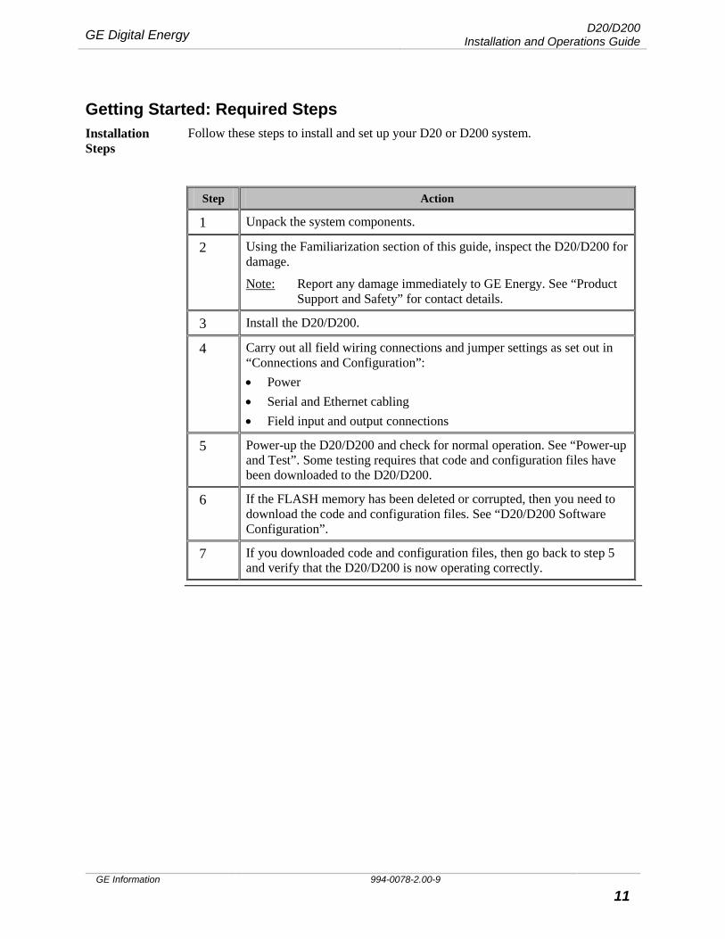
Getting Started: Required Steps Installation Steps
Follow these steps to install and set up your D20 or D200 system.
Step Action
1 Unpack the system components.
2 Using the Familiarization section of this guide, inspect the D20/D200 for damage.
Note: Report any damage immediately to GE Energy. See “Product Support and Safety” for contact details.
3 Install the D20/D200.
4 Carry out all field wiring connections and jumper settings as set out in “Connections and Configuration”: • Power • Serial and Ethernet cabling • Field input and output connections
5 Power-up the D20/D200 and check for normal operation. See “Power-up and Test”. Some testing requires that code and configuration files have been downloaded to the D20/D200.
6 If the FLASH memory has been deleted or corrupted, then you need to download the code and configuration files. See “D20/D200 Software Configuration”.
7 If you downloaded code and configuration files, then go back to step 5 and verify that the D20/D200 is now operating correctly.
D20/D200 Installation and Operations Guide GE Digital Energy
994-0078-2.00-9 GE Information
12
Getting Started: Required Steps, continued
Installation Tools, Equipment and Accessories
Before you begin to install your D20/D200, gather the required tools, equipment and accessories:
• Flathead screwdriver with 0.6 x 3.5 mm blade (for terminal block wiring) • #2 Phillips screwdriver (for rack mounting the unit) • Wire cutters (for field wiring) • Wire strippers (for field wiring) • Wire crimping tool (for field wiring) • Tie-wraps (for organizing wiring and cables) • Multimeter (for testing voltages and I/O points) • Needle nose pliers (for setting jumpers, for example) • PROM puller (only required if you are going to be upgrading or installing
PROMs in the field) Depending on how you are going to be labeling your cables and wires, you may need:
• Heat shrink label printer • Heat gun (for shrinking)
GE Digital Energy D20/D200 Installation and Operations Guide
GE Information 994-0078-2.00-9 13
Familiarization Introduction Use this section to become familiar with the various components that make up a D20
or D200 system.
What are the D20 and D200?
The D20 is a standalone remote terminal unit (RTU). It consists of one or more main processor boards, peripheral I/O modules, termination panels, power supply, and communication equipment.
These components, combined with software applications, form the D20 RTU System.
The D20 acts as a data concentrator and central processor. Field data gathered through the peripheral modules and external Intelligent Electronic Devices (IEDs) are stored in the system database and can be accessed by the application programs loaded into the D20.
The D20 design has horizontally mounted processor boards, with multiple boards in some versions.
The D200 shares the same overall design concept as the D20 but it has vertically mounted processor boards. The D200 can use multiple D20ME/ME II processor boards, up to a maximum of eight nodes.
The D20 and D200 are available in a Kit form, for self-assembly, and as factory-assembled RTUs.
Separate Peripherals
Peripheral I/O boards operate independently of the main chassis and main processors. This means that: • You can use a D20 or a D200 without direct connection to peripheral boards so
that it acts as a Master Data Concentrator to other RTUs. • You can hot-swap the peripherals without powering down the main processor.
Assembling a D20
Many add-on options are available for the D20 & D200 systems, to provide different operational performance and functions. Typically, the D20 and D200 systems will consist of a Main Chassis with required Peripheral I/O boards.
D20/D200 Installation and Operations Guide GE Digital Energy
994-0078-2.00-9 GE Information
14
Familiarization, continued
D20 Chassis The D20 chassis is available in two versions:
• Standard single slot with one horizontal Eurocard slot for mounting the D20ME/ME II board for the non-VME compatible version.
• Full VME equipped with five horizontal expansion slots for VME compatible printed circuit boards.
Table The D20 has a 3U horizontal slot chassis for 19” rack mounting. There are two types of chassis:
Chassis Type Part # Description
D20 non-VME
(1 slot horizontal)
500-0305 Single Slot MX Chassis with backplane, external power connections, and 7 serial I/O ports
D20 VME
(5 slot horizontal)
500-0280 MX Chassis with 5 card VME backplane
Chassis Compatibility
See “Appendix A: Product Combinations”, for the possible matching of main processor board, Ethernet and memory expansion card combinations with Chassis types.
D20 Kit Components
D20 Main Chassis kit contains: • Chassis • Main processor board • Power supply • WESMAINT maintenance port cable • Software loaded into the main processor, See “D20ME/ME II Factory Fitted
Software” on page 25. • Termination panel: included on the 500-0305 single-slot, not included on the
500-0280 MX with VME backplane. Modems are options for the Main Chassis kit.
GE Digital Energy D20/D200 Installation and Operations Guide
GE Information 994-0078-2.00-9 15
Familiarization, continued
Other Components
To complete a basic D20 implementation, several other components are required: • Peripheral I/O modules • D.20 Link for communication between the main board and the peripherals • Interposing Relay Panels, the need for which depends upon the load
characteristics of the device that is controlled by the D20K or D20C control peripherals. If this rating exceeds the contact rating of the D20K or D20C control peripheral boards, then an Interposing Relay Panel is required. See “Interposing Relays” page 34.
• When using bit-based synchronous protocols a Universal Protocol Converter (UPC) board is required to convert from byte to bit and back. The D20/D200 communicates asynchronously over its serial ports. Note: The jumper settings on the UPC are protocol-specific. See “Universal
Protocol Converter” page 34.
Other System Configurations
• If you are building a redundant system, you will need additional cables to link the active and standby units. See “D20/D200 Redundancy”, page 39.
D20/D200 Installation and Operations Guide GE Digital Energy
994-0078-2.00-9 GE Information
16
Familiarization, continued
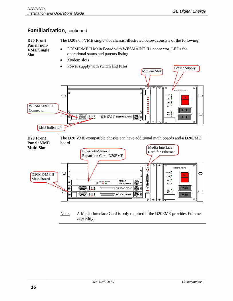
D20 Front Panel: non-VME Single Slot
The D20 non-VME single-slot chassis, illustrated below, consists of the following:
• D20ME/ME II Main Board with WESMAINT II+ connector, LEDs for operational status and patents listing
• Modem slots • Power supply with switch and fuses
D20 Front Panel: VME Multi Slot
The D20 VME-compatible chassis can have additional main boards and a D20EME board.
Note: A Media Interface Card is only required if the D20EME provides Ethernet capability.
Modem Slot Power Supply
WESMAINT II+ Connector
LED Indicators
D20ME/ME II Main Board
Ethernet/Memory Expansion Card, D20EME
Media Interface Card for Ethernet
GE Digital Energy D20/D200 Installation and Operations Guide
GE Information 994-0078-2.00-9 17
Familiarization, continued
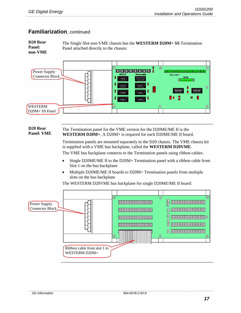
D20 Rear Panel: non-VME
The Single Slot non-VME chassis has the WESTERM D20M+ SS Termination Panel attached directly to the chassis:
D20 Rear Panel: VME
The Termination panel for the VME version for the D20ME/ME II is the WESTERM D20M+. A D20M+ is required for each D20ME/ME II board.
Termination panels are mounted separately to the D20 chassis. The VME chassis kit is supplied with a VME bus backplane, called the WESTERM D20VME. The VME bus backplane connects to the Termination panels using ribbon cables:
• Single D20ME/ME II to the D20M+ Termination panel with a ribbon cable from Slot 1 on the bus backplane
• Multiple D20ME/ME II boards to D20M+ Termination panels from multiple slots on the bus backplane
The WESTERM D20VME bus backplane for single D20ME/ME II board:
Power Supply Connector Block
Ribbon cable from slot 1 to WESTERM D20M+
Power Supply Connector Block
WESTERM D20M+ SS Panel
D20/D200 Installation and Operations Guide GE Digital Energy
994-0078-2.00-9 GE Information
18
Familiarization, continued
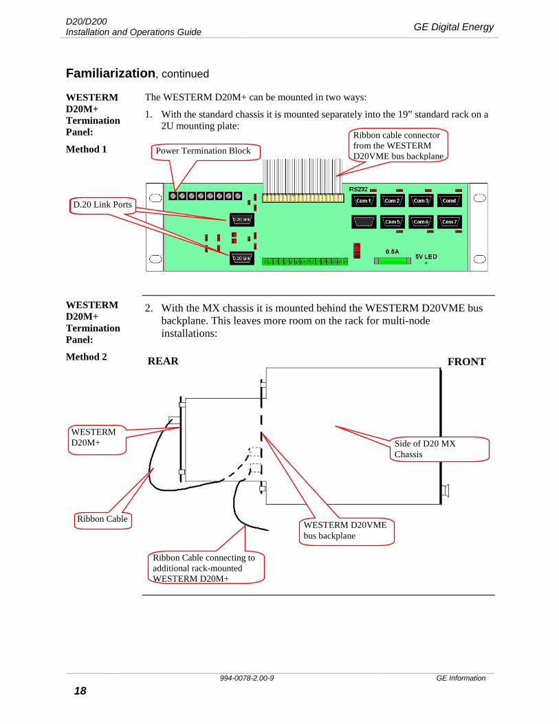
WESTERM D20M+ Termination Panel:
Method 1
The WESTERM D20M+ can be mounted in two ways:
1. With the standard chassis it is mounted separately into the 19” standard rack on a 2U mounting plate:
WESTERM D20M+ Termination Panel:
Method 2
2. With the MX chassis it is mounted behind the WESTERM D20VME bus backplane. This leaves more room on the rack for multi-node installations:
Side of D20 MX Chassis
Ribbon Cable
FRONT REAR
WESTERM D20M+
WESTERM D20VME bus backplane
Ribbon cable connector from the WESTERM D20VME bus backplane Power Termination Block
Ribbon Cable connecting to additional rack-mounted WESTERM D20M+
D.20 Link Ports D.20 Link Ports
GE Digital Energy D20/D200 Installation and Operations Guide
GE Information 994-0078-2.00-9 19
Familiarization, continued
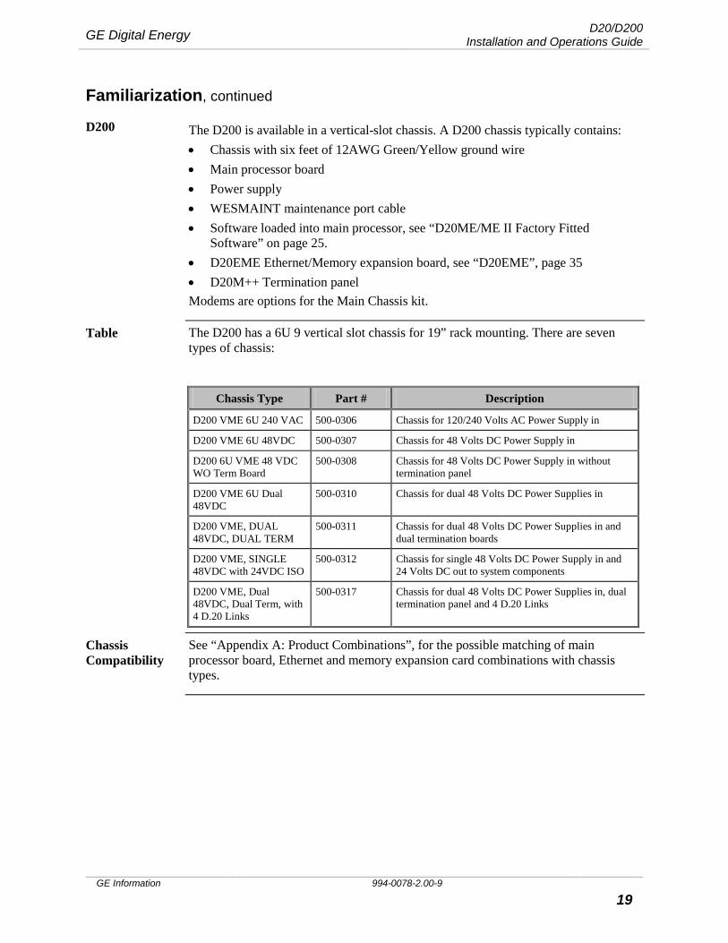
D200 The D200 is available in a vertical-slot chassis. A D200 chassis typically contains: • Chassis with six feet of 12AWG Green/Yellow ground wire • Main processor board • Power supply • WESMAINT maintenance port cable • Software loaded into main processor, see “D20ME/ME II Factory Fitted
Software” on page 25. • D20EME Ethernet/Memory expansion board, see “D20EME”, page 35 • D20M++ Termination panel Modems are options for the Main Chassis kit.
Table The D200 has a 6U 9 vertical slot chassis for 19” rack mounting. There are seven types of chassis:
Chassis Type Part # Description
D200 VME 6U 240 VAC 500-0306 Chassis for 120/240 Volts AC Power Supply in
D200 VME 6U 48VDC 500-0307 Chassis for 48 Volts DC Power Supply in
D200 6U VME 48 VDC WO Term Board
500-0308 Chassis for 48 Volts DC Power Supply in without termination panel
D200 VME 6U Dual 48VDC
500-0310 Chassis for dual 48 Volts DC Power Supplies in
D200 VME, DUAL 48VDC, DUAL TERM
500-0311 Chassis for dual 48 Volts DC Power Supplies in and dual termination boards
D200 VME, SINGLE 48VDC with 24VDC ISO
500-0312 Chassis for single 48 Volts DC Power Supply in and 24 Volts DC out to system components
D200 VME, Dual 48VDC, Dual Term, with 4 D.20 Links
500-0317 Chassis for dual 48 Volts DC Power Supplies in, dual termination panel and 4 D.20 Links
Chassis Compatibility
See “Appendix A: Product Combinations”, for the possible matching of main processor board, Ethernet and memory expansion card combinations with chassis types.
D20/D200 Installation and Operations Guide GE Digital Energy
994-0078-2.00-9 GE Information
20
Familiarization, continued
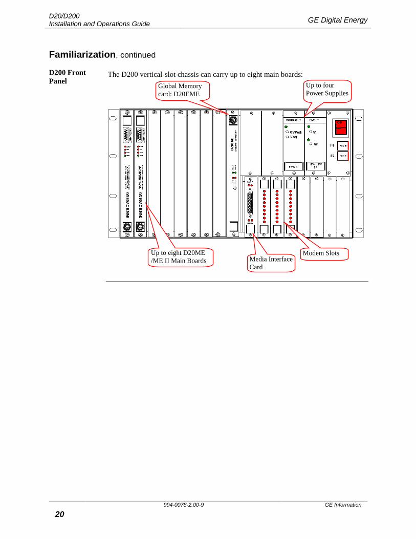
D200 Front Panel
The D200 vertical-slot chassis can carry up to eight main boards:
Global Memory card: D20EME
Up to four Power Supplies
Modem Slots Up to eight D20ME /ME II Main Boards Media Interface
Card
GE Digital Energy D20/D200 Installation and Operations Guide
GE Information 994-0078-2.00-9 21
Familiarization, continued
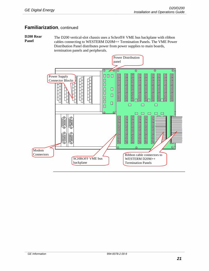
D200 Rear Panel
The D200 vertical-slot chassis uses a Schroff® VME bus backplane with ribbon cables connecting to WESTERM D20M++ Termination Panels. The VME Power Distribution Panel distributes power from power supplies to main boards, termination panels and peripherals.
Ribbon cable connectors to WESTERM D20M++ Termination Panels
Ribbon cable connectors to WESTERM D20M++ Termination Panels
SCHROFF VME bus backplane
Power Distribution panel
Power Supply Connector Blocks
Modem Connectors

D20/D200 Installation and Operations Guide GE Digital Energy
994-0078-2.00-9 GE Information
22
Familiarization, continued
WESTERM D20M++ Termination Panel
The D200 uses the WESTERM D20M++ Termination Panel. Up to four D20ME/ME II boards can be connected to each Termination Panel.
Note There are cases when you will need a second termination panel:
• If you have more than four main boards and you want to utilize at least one serial communication port for each board
• If more than 28 serial ports are required Contact GE Energy for further information.
Banks of RS-232 Serial Communication Ports for separate nodes
Power Termination Block
Grounding Block
Ribbon cable connections Ribbon cable connections Ribbon cable connections Ribbon cable connectors D.20 Link Ports
GE Digital Energy D20/D200 Installation and Operations Guide
GE Information 994-0078-2.00-9 23
Familiarization, continued
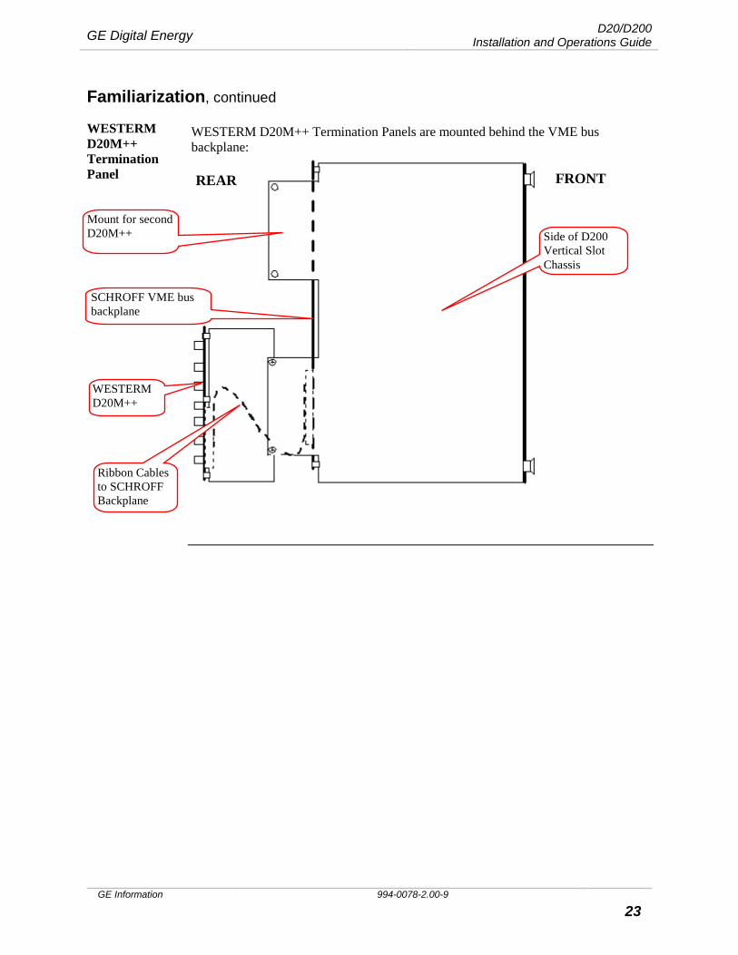
WESTERM D20M++ Termination Panel
WESTERM D20M++ Termination Panels are mounted behind the VME bus backplane:
FRONT REAR
Side of D200 Vertical Slot Chassis
SCHROFF VME bus backplane
Ribbon Cables to SCHROFF Backplane
WESTERM D20M++
Mount for second D20M++

D20/D200 Installation and Operations Guide GE Digital Energy
994-0078-2.00-9 GE Information
24
Familiarization, continued
D20ME Main Module
The D20ME is the: • Main module of the D20/D200. It functions as a data concentrator and central
processor of field data, and • Acts as a master controller over other D20 peripheral I/O modules, which act as
slaves.
The D20 I/O peripheral modules perform the primary processing of data. This increases the speed and efficiency of the D20 by reducing the workload on the main processor.
D20ME: Four Versions
• The D20ME non-VME is designed for use in single-processor D20 devices • The D20ME VME is designed to fit in a standard D20 or D200 VME chassis and
has access to: − External global memory − VME-based peripherals, such as Ethernet cards
• The D20ME II is available in VME and non-VME versions. It is functionally identical to the D20ME; however, it has the added capability to select, on a per-channel basis, RS-232 or RS-485 interfacing.
Table The following table lists D20ME/ME II part numbers and typical applications.
Board Type Part # Description
D20ME 526-2004 D20ME module suitable for non-VME D20 (single processor) applications.
D20ME – VME 526-2005 D20ME module suitable for VME D20 and D200 applications requiring multiple processors and/or Ethernet support.
D20ME II (non VME) 526-2006 D20ME II module, supporting RS-232 and RS-485 interfaces, suitable for non-VME (single processor) applications.
D20ME II (VME) 526-2007 D20ME II module, supporting RS-232 and RS-485 interfaces, suitable for VME D20 and D200 applications requiring multiple processors and/or Ethernet support.
Note All D20ME module types can be used with D20 Base firmware or CCU Base firmware.
You must select which base system to use when choosing the module type in Config Pro.
LED Indicators See “Operations: D20ME/ME II Main Board” on page 115 for information about LED indicators.
GE Digital Energy D20/D200 Installation and Operations Guide
GE Information 994-0078-2.00-9 25
Familiarization, continued
D20ME/ME II Factory Fitted Software
The D20ME/ME II has Base software, which resides on the BootROM installed at the factory.
Each D20ME/ME II board undergoes factory testing. The level of testing depends on the type of system you have ordered. See “D20/D200 Software Configuration” page 99.
D20ME: Serial I/O Architecture
• Supports eight serial channels, and utilizes a serial I/O (SIO) chip (called the "Octart")
• Serial channels are routed to the DB-9 connectors on the back of the chassis • One channel (COM0) from the rear panel is also routed to the WESMAINT
DB-9 connector on the face plate of the processor card.
Note: Use only a standard PROMAINT cable (GE Energy part number 977-0048) when you are connecting to the D20ME or ME II’s front-panel WESMAINT connector. Use of any other cable may cause serious damage.
Serial Performance
The following table gives the serial communication performance of the D20ME. The information below is provided only as a guideline for comparison.
Note 1: The aggregate limits of the modules are dependent on the quantity and processing load of other applications running in the modules.
Note 2: The actual communication speed of any port is defined by and limited to speeds that individual applications support. Some applications and base systems may not support baud rates higher than 9600.
Parameter D20ME/ME II Limit
Aggregate serial communications limit of module, half-duplex
7 ports at 38.4 kbps, plus WESMAINT
Enhanced Feature: 68K Monitor Speed Change
Using the Monitor's BAUD command, the communication speed of the WESMAINT port can be changed to a higher or lower rate. The most common reasons for increasing the WESMAINT port speed are to reduce the time required to:
• Download application code file to the flash memory, and to • Carry out a configuration download. Refer to “Appendix B: Changing the Baud Rate”, page 127 for more information.
D20/D200 Installation and Operations Guide GE Digital Energy
994-0078-2.00-9 GE Information
26
Familiarization, continued
D20: Supplying Power
There are various power supply options for a D20 system:
• Standard Chassis-mounted Power Supplies • Auxiliary Power Supplies • Redundant Power Supplies
D20 Power Supply
The chassis-mounted power supply modules are switch-mode converters that provide output power for the D20ME/ME II board, VME cards, modems and D20 Peripheral I/O modules, as required.
External Power Supplies
If you have an extended system with more than five peripherals, then the chassis-mounted D20 Power Supply will not be adequate. You will need to install an external power supply.
Redundant Power Supplies
A redundant power supply provides fail-over protection and ensures continuous power to the unit.
GE Digital Energy D20/D200 Installation and Operations Guide
GE Information 994-0078-2.00-9 27
Familiarization, continued
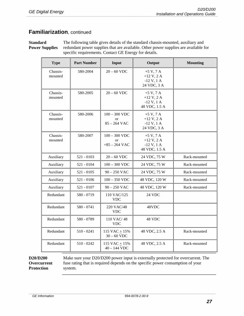
Standard Power Supplies
The following table gives details of the standard chassis-mounted, auxiliary and redundant power supplies that are available. Other power supplies are available for specific requirements. Contact GE Energy for details.
Type Part Number Input Output Mounting
Chassis-mounted
580-2004 20 – 60 VDC +5 V, 7 A +12 V, 2 A -12 V, 1 A
24 VDC, 3 A
Chassis-mounted
580-2005 20 – 60 VDC +5 V, 7 A +12 V, 2 A -12 V, 1 A
48 VDC, 1.5 A
Chassis-mounted
580-2006 100 – 300 VDC or
85 – 264 VAC
+5 V, 7 A +12 V, 2 A -12 V, 1 A
24 VDC, 3 A
Chassis-mounted
580-2007 100 – 300 VDC or
+85 – 264 VAC
+5 V, 7 A +12 V, 2 A -12 V, 1 A
48 VDC, 1.5 A
Auxiliary 521 - 0103 20 – 60 VDC 24 VDC, 75 W Rack-mounted
Auxiliary 521 - 0104 100 – 300 VDC 24 VDC, 75 W Rack-mounted
Auxiliary 521 - 0105 90 – 250 VAC 24 VDC, 75 W Rack-mounted
Auxiliary 521 - 0106 100 – 350 VDC 48 VDC, 120 W Rack-mounted
Auxiliary 521 - 0107 90 – 250 VAC 48 VDC, 120 W Rack-mounted
Redundant 580 - 0719 110 VAC/125 VDC
24 VDC
Redundant 580 - 0741 220 VAC/48 VDC
48VDC
Redundant 580 - 0789 110 VAC/ 48 VDC
48 VDC
Redundant 510 - 0241 115 VAC + 15% 30 – 60 VDC
48 VDC, 2.5 A Rack-mounted
Redundant 510 - 0242 115 VAC + 15% 40 – 144 VDC
48 VDC, 2.5 A Rack-mounted
D20/D200 Overcurrent Protection
Make sure your D20/D200 power input is externally protected for overcurrent. The fuse rating that is required depends on the specific power consumption of your system.
D20/D200 Installation and Operations Guide GE Digital Energy
994-0078-2.00-9 GE Information
28
Familiarization, continued
Modems Two D20 modems are available for communications to a host computer or to other IEDs:
• WESDAC 202/V.23 is a 1200-baud Bell 202 or CCITT V.23 standard modem designed for 300 to 1200 baud asynchronous operation on unconditioned lines and supports the majority of SCADA/EMS applications. It is available in a 19" rack mount or 3U vertical mount configuration in the D20 chassis.
• WESDAC 212/V.23 is a 1200-baud Bell 212 standard modem, (auto answer only), used for dial-up access to the D20. This modem is available for mounting only as a 3U vertical mount.
Third-party Modems
Third-party modems can be used to meet specific customer requirements. These modems are connected to the D20/D200 via standard RS-232 connections.
WESMAINT Cable
For maintenance work on a D20 or D200 you will need a WESMAINT port cable to connect to the D20 and D200. These are available in either 8’ or 15’ lengths.
Also use this type of cable to connect to Promaint for maintenance work on the D20 Peripheral I/O modules.
For WESMAINT cable DB-9 connector pinouts, see “WESMAINT Cable Pinouts”, page 88.
I/O Peripherals Peripheral I/O modules are intelligent modules containing an on-board microprocessor. They are configured as slaves to the D20ME/ME II main processor. In this way, specific I/O processing is distributed throughout the RTU to the appropriate I/O module. There are five types of I/O peripherals:
• D20A analog input • D20S digital inputs • D20K digital output • D20C combination input/output • D20AC alternating current analog input Optional High Voltage peripherals are available for the D20 and D200.
GE Digital Energy D20/D200 Installation and Operations Guide
GE Information 994-0078-2.00-9 29
Familiarization, continued
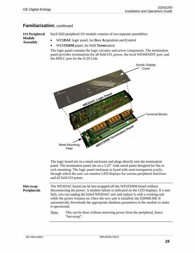
I/O Peripheral Module Assembly
Each D20 peripheral I/O module consists of two separate assemblies:
• WESDAC logic panel, for Data Acquisition and Control • WESTERM panel, for field Termination The logic panel contains the logic circuitry and active components. The termination panel provides terminations for all field I/O, power, the local WESMAINT port, and the HDLC port for the D.20 Link.
Acrylic DisplayCover
Terminal Blocks
WESTERM Termination Panel
WESDAC Logic Panel
Metal MountingPlate
The logic board sits in a metal enclosure and plugs directly into the termination panel. The termination panel sits on a 5.25" wide metal panel designed for flat or rack mounting. The logic panel enclosure is faced with semi-transparent acrylic, through which the user can monitor LED displays for various peripheral functions and all field I/O points.
Hot-swap Peripherals
The WESDAC board can be hot-swapped off the WESTERM board without disconnecting the power. A module failure is indicated on the LED displays. If a unit fails, you can unplug the failed WESDAC unit and replace it with a working unit while the power remains on. Once the new unit is installed, the D20ME/ME II automatically downloads the appropriate database parameters to the module to make it operational.
Note: This can be done without removing power from the peripheral, hence “hot-swap”.

D20/D200 Installation and Operations Guide GE Digital Energy
994-0078-2.00-9 GE Information
30
Familiarization, continued
D20A Analog Input Peripheral
The D20A peripheral is a 32-point analog input interface module for the D20.
The D20A WESDAC logic module plugs directly into a D20A WESTERM termination panel, which provides three screw compression type terminals for each input (+, -, shield) and sockets for analog scaling networks. DB25 and barrier strip termination options are also available. Provision is made for configuring analog loop supply from the D20A or externally. Loop voltage is fused and can be monitored.
An on/off-line indication is passed to the D20/D200, where it can be used as a pseudo status.
D20S Digital Input Peripheral
The D20S can accept up to 64 digital inputs.
The WESDAC D20S logic module plugs directly into a WESTERM D20S termination panel equipped with screw compression type terminals for field terminations. DB25 and barrier strip termination options are also available.
The D20S termination panel is jumper-configurable for contact wetting supplied from the D20S or an external source. Wetting voltage is fused and monitored.
An on/off-line indication is passed to the D20/D200, where it can be used as a pseudo status.
D20K Control Output Peripheral
The D20K is a 32-point control output interface module for the D20. It supports up 32 trip/close pairs, 32 individual controls and/or 16 raise/lower pairs.
The D20K logic module plugs directly into a D20K termination panel, which is equipped with screw compression type field terminations. DB25 and barrier strip termination options are also available.
A Local/Remote switch and control output fusing are also provided. The Local/Remote switch is a manually operated switch used to disable D20K relay coil power during maintenance. An on/off-line indication is passed to the D20/D200, where it can be used as a pseudo status. Fuse protection complete with monitoring of fuse status is provided for control output power supplied from an internal source.
Interposing relays can be supplied using D20KI panels.

GE Digital Energy D20/D200 Installation and Operations Guide
GE Information 994-0078-2.00-9 31
Familiarization, continued
D20C Combination I/O Peripheral
The D20C is a combination I/O module that is used for small-point-count applications. The D20C can be configured with:
• 16 digital inputs
• 8 momentary or dual function trip/close control outputs
• 16 analog inputs
• 8 analog inputs and 8 analog outputs. The D20C performs all the I/O processes similar to the other D20 I/O modules, but uses a faster clock speed to meet the increased processing power demand.
Interposing relays may be supplied using a WESTERM D20KI, as with the D20K.
A Local/Remote switch is provided to turn off relay coil power, and put the module off-line. An on/off-line indication is sent to the D20/D200, which is available to the host as a pseudo-status.
D20C Daughter Boards
D20C1 and D20C2 daughter boards are available as options for the D20C peripheral. They are mounted on the D20C WESDAC to give additional analog inputs and analog outputs, as shown below:
Table: D20C Options
WESDAC Board Digital Inputs
Digital Outputs
Analog Inputs
Analog Outputs
D20C 16 8
D20C with D20C1 Daughter Board 16 8 16
D20C with D20C2 Daughter Board 16 8 8 8
D20AC Analog Input Peripheral
The D20AC peripheral, which is the alternating current analog input module for the D20 product line, provides:
• Up to six 50/60Hz voltage inputs • Up to nine 50/60Hz current inputs • One DC input To provide isolation, the termination panel uses current and potential transformers on the AC inputs, and an isolation transformer on the DC input. The current inputs utilize a compressor to achieve an eight-times reduction of the input signal. The AC current and voltage inputs, and the DC input are buffered before being multiplexed into the analog-to-digital (A/D) converter section.
D20/D200 Installation and Operations Guide GE Digital Energy
994-0078-2.00-9 GE Information
32
Familiarization, continued
Promaint Promaint is the maintenance facility for the peripheral modules. Use it to:
• View data • Force control points to verify that the board is functioning correctly • Calibrate a D20C Board Note Promaint access to the D20C board requires an additional daughter card,
the WESDAC D20C WESMAINT Interface: 540 –0162.
D.20 Peripheral Link
Communications between the D20 main processor and the D20 peripheral I/O modules are carried over a high-speed, high-level data link (HDLC) called the D.20 Link. The D.20 Link has the following features:
• RS-485 serial link, half duplex, 250 kbps • D.20 protocol using HDLC format with Manchester encoding • Supports up to 31 D20 I/O peripheral modules in a standard configuration • Repeater/extension modules may be used to extend this limit to a maximum of
128 (D20) and 256 (D200) peripheral I/O modules Media options: • RS-485, 24 AWG twisted pair, for applications up to 330 meters • Multi-Mode Glass Fiber (GFO), up to 2 km • Plastic Fiber (PFO), up to 60 meters Notes: If you are using the D20 or D200 as a Master Data Concentrator, then the
D.20 Link connectors are not used.
The D.20 Link can also be used to supply power to peripherals on smaller D20 horizontal slot chassis systems. See “Peripherals: Supplying Power”, page 54.
Second D.20 Link
Redundant D.20 communication channels are available on all peripherals. Daughter boards are required to support this functionality:
• Part number: 540-0207, for the A, S and K boards • Part number: 540-0209 for the C board
GE Digital Energy D20/D200 Installation and Operations Guide
GE Information 994-0078-2.00-9 33
Familiarization, continued
Extended Communi-cations
To extend communications to multiple peripherals, use the D.20 Communications Interface or the D.20 Splitter, each of which will allow peripherals to be sited remotely from the D20.
In conjunction with the D.20 RS-485 Adaptor, the D.20 Communications Interface acts as a communication repeater to overcome the limit of 31 peripherals on a single RS-485 link.
The D.20 Communications Interface can be used in conjunction with any of the following plug-in adaptors:
• D.20 RS-485 Interface • GFO/PFO Adaptors The D.20 Splitter can be used only with the GFO/PFO adaptors.
D.20 Comm Interface
Use the D.20 Communication Interface module when you require one-to-one communication links with peripherals.
D.20 Splitter Use the D.20 Splitter when you require one-to-four communication links with peripherals, especially if peripherals are clustered in different areas of the substation.
D.20 RS-485 Interface
The D.20 RS-485 Interface provides the repeater function, which can only be implemented on the D.20 Communications Interface.
GFO and PFO Adaptors
Glass Fiber Optic (GFO) and Plastic Fiber Optic (PFO) adaptors are used to provide either glass or plastic fiber optical cable extensions to the D.20 Link. These allow interference free links to peripherals that are sited at a remote distance from the main D20 installation.
Extended Power
When power requirements for multiple peripherals exceed the base system limitations, use the D.20 DC Interface module.
D.20 DC Interface
The D.20 DC Interface module is used:
• As power input for additional peripherals on a D.20 Link • For power supply to peripherals on a D200 vertical slot multi-node
implementation which cannot use the D20 Link for peripheral power supply
D20/D200 Installation and Operations Guide GE Digital Energy
994-0078-2.00-9 GE Information
34
Familiarization, continued
Interposing Relays
The required rating of the relays on the K and C boards is determined by the loading characteristics of the device that the boards control.
If the load rating of the controlled device exceeds the K or C board relay rating, then you will need an Interposing Relay panel.
Universal Protocol Converter
A Universal Protocol Converter (UPC) is required when the D20/D200 has to communicate with a device that uses a synchronous communications format. The function of the UPC is to convert between the D20/D200’s asynchronous format, and the device’s synchronous format.
See “Universal Protocol Converter”, page 88 for UPC configuration.
GE Digital Energy D20/D200 Installation and Operations Guide
GE Information 994-0078-2.00-9 35
Familiarization, continued
D20EME The D20 Ethernet/Memory Expansion (EME) kit can be installed in a D20 or D200 to add expanded (Global) memory and/or Ethernet capability.
D20EME kits are offered in a variety of options to address common requirements for D20 and D200 systems, including:
• Ethernet only systems • Expanded (or Global) memory only applications • Combined Ethernet and Global memory systems
Applications of the D20EME
The D20EME kit can be used in two main applications:
• New installations • Upgrade or replacement applications.
Upgrades and Replacements
• When upgrading a D20 VME or D200 from a GreenSpring Ethernet card to an Ethernet EME card, you need to re-install software into the D20ME/ME II processor.
• Upgrading a D200 to use a memory-only EME does not require new firmware, but may require a new configuration.
• If you are adding Ethernet capability to an existing D20 VME, first verify that the D20’s power supply is capable of handling the additional load. For further advice, contact GE for assistance.
• The interconnect cable that links the EME main board to the MIC card must be routed inside the D20 or D200 chassis. Routing the cable outside the chassis may cause excessive EMI radiation and/or interfere with operation.
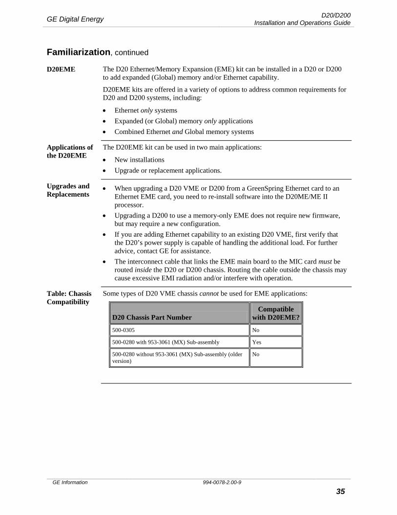
Table: Chassis Compatibility
Some types of D20 VME chassis cannot be used for EME applications:
D20 Chassis Part Number Compatible
with D20EME?
500-0305 No
500-0280 with 953-3061 (MX) Sub-assembly Yes
500-0280 without 953-3061 (MX) Sub-assembly (older version)
No
D20/D200 Installation and Operations Guide GE Digital Energy
994-0078-2.00-9 GE Information
36
Familiarization, continued
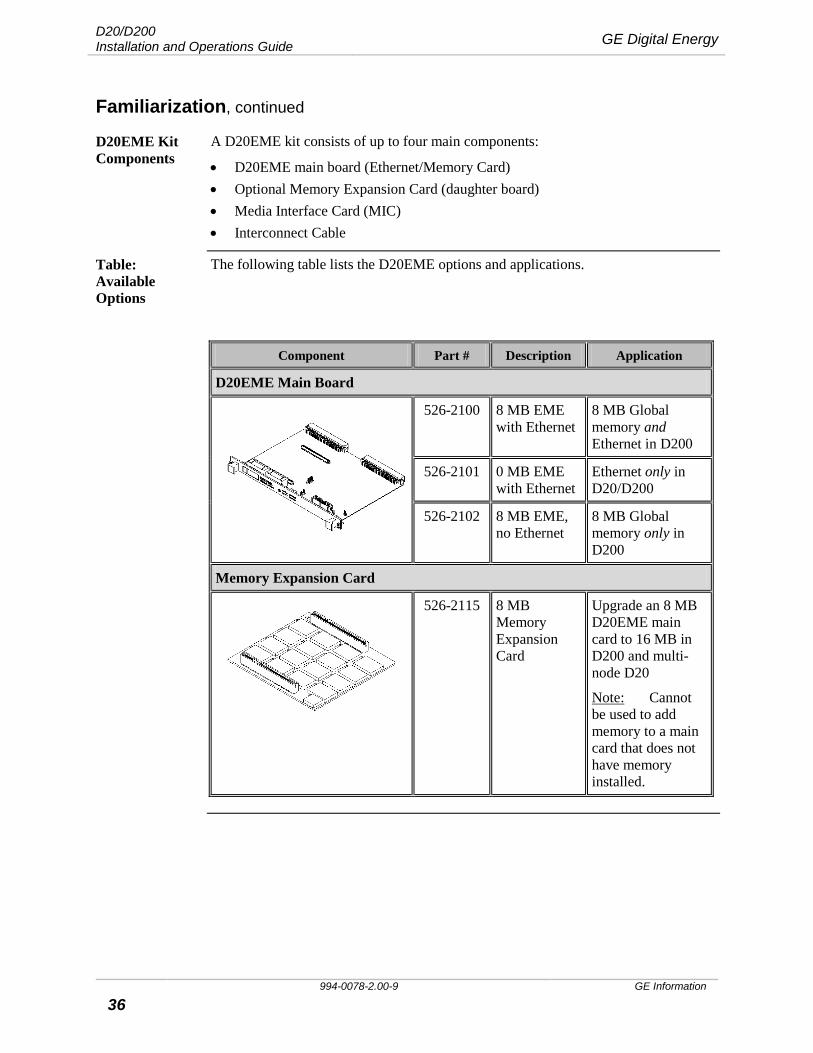
D20EME Kit Components
A D20EME kit consists of up to four main components:
• D20EME main board (Ethernet/Memory Card) • Optional Memory Expansion Card (daughter board) • Media Interface Card (MIC) • Interconnect Cable
Table: Available Options
The following table lists the D20EME options and applications.
Component Part # Description Application
D20EME Main Board
526-2100 8 MB EME with Ethernet
8 MB Global memory and Ethernet in D200
526-2101 0 MB EME with Ethernet
Ethernet only in D20/D200
526-2102 8 MB EME, no Ethernet
8 MB Global memory only in D200
Memory Expansion Card
526-2115 8 MB Memory Expansion Card
Upgrade an 8 MB D20EME main card to 16 MB in D200 and multi-node D20
Note: Cannot be used to add memory to a main card that does not have memory installed.

GE Digital Energy D20/D200 Installation and Operations Guide
GE Information 994-0078-2.00-9 37
Familiarization, continued
Table: Available Options (continued)
Component Part # Description Application
Media Interface Card
526-2110 10BASE-T, Ethernet
Twisted-pair Ethernet dual interface used with Ethernet EME card in D20/D200.
526-2111 10BASE2, Ethernet
Coaxial Ethernet dual interface used with Ethernet EME card in D20/D200.
526-2112 10BASE-FL, Ethernet
Fiber-optic Ethernet dual interface used with Ethernet EME card in D20/D200.
Interconnect Cable
977-0298
Interconnect Cable for Ethernet kits
Included only with “Ethernet” kits.
Carries power and Ethernet signaling from the main EME card to the MIC card.
Notes • A Memory Expansion only kit contains the Memory Expansion Card only • The main boards used in D20s or D200s must have CCU (Central Control Unit,
term used to describe the D200 multi-processor system) base software to access either the Ethernet or global memory facilities over a VME backplane
D20/D200 Installation and Operations Guide GE Digital Energy
994-0078-2.00-9 GE Information
38
Familiarization, continued
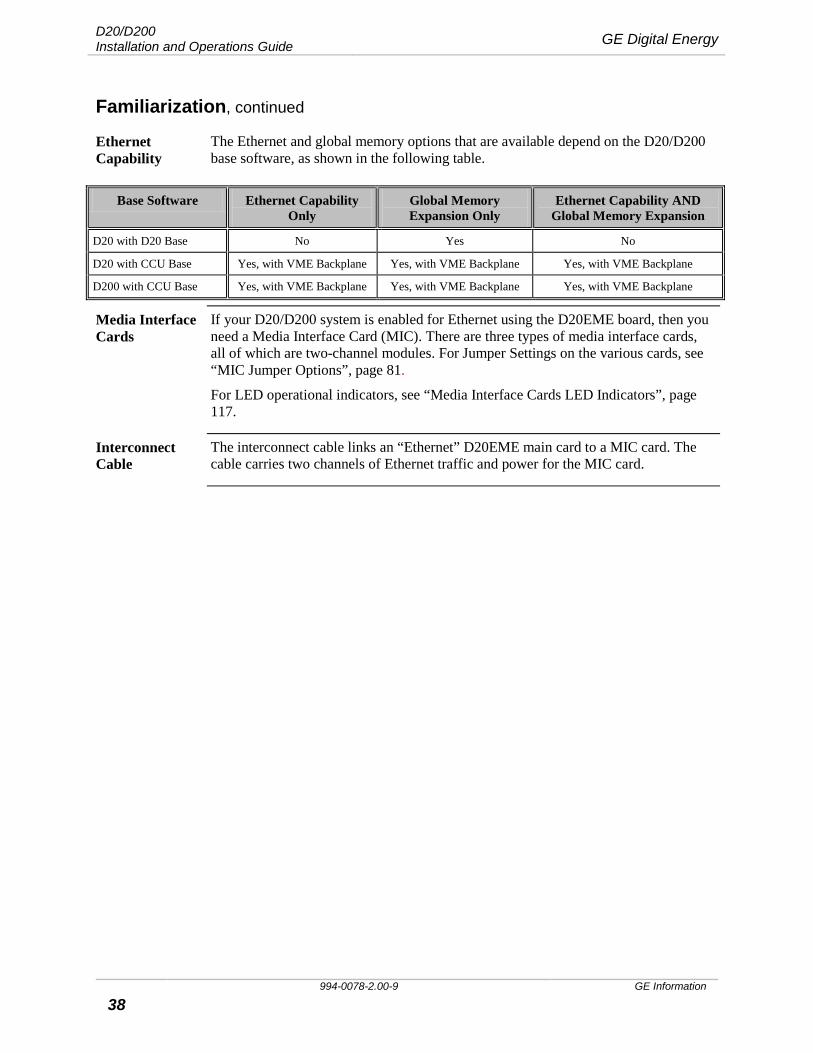
Ethernet Capability
The Ethernet and global memory options that are available depend on the D20/D200 base software, as shown in the following table.
Base Software Ethernet Capability Only
Global Memory Expansion Only
Ethernet Capability AND Global Memory Expansion
D20 with D20 Base No Yes No
D20 with CCU Base Yes, with VME Backplane Yes, with VME Backplane Yes, with VME Backplane
D200 with CCU Base Yes, with VME Backplane Yes, with VME Backplane Yes, with VME Backplane
Media Interface Cards
If your D20/D200 system is enabled for Ethernet using the D20EME board, then you need a Media Interface Card (MIC). There are three types of media interface cards, all of which are two-channel modules. For Jumper Settings on the various cards, see “MIC Jumper Options”, page 81.
For LED operational indicators, see “Media Interface Cards LED Indicators”, page 117.
Interconnect Cable
The interconnect cable links an “Ethernet” D20EME main card to a MIC card. The cable carries two channels of Ethernet traffic and power for the MIC card.
GE Digital Energy D20/D200 Installation and Operations Guide
GE Information 994-0078-2.00-9 39
Familiarization, continued
D20/D200 Redundancy
D20/D200 equipment redundancy requires: • A second CCU (Central Control Unit, a term used to describe the D200 multi-
processor system), and • One or more RS-232 Switch Panels. Note: The quiescent current of the +12 V power supply input on the RS-232 Switch
Panel is 15 mA. The maximum power requirement on the +12 V input during operation is 230 mA.
Through a toggle switch on the RS-232 Switch Panel, you designate one of the CCUs as the Active unit. If the Active unit hardware or software fails, the Active CCU is automatically switched offline, and the Standby unit is switched through to the field equipment (i.e., it is made Active).
The RS-232 Switch Panel is not equipped with EMI protection circuitry. If the connection length exceeds 3m, a Serial Surge Protection Panel (GE item number 540-0249) or equivalent protection device should be installed.
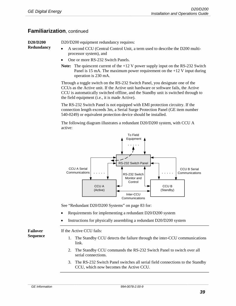
The following diagram illustrates a redundant D20/D200 system, with CCU A active:
CCU A(Active)
CCU B(Standby)
RS-232 SwitchMonitor and
Control
Inter-CCUCommunications
To Field Equipment
CCU A SerialCommunications
CCU B SerialCommunications. . . . . . . . . .
. . . . .
RS-232 Switch Panel
See “Redundant D20/D200 Systems” on page 83 for:
• Requirements for implementing a redundant D20/D200 system
• Instructions for physically assembling a redundant D20/D200 system
Failover Sequence
If the Active CCU fails:
1. The Standby CCU detects the failure through the inter-CCU communications link.
2. The Standby CCU commands the RS-232 Switch Panel to switch over all serial connections.
3. The RS-232 Switch Panel switches all serial field connections to the Standby CCU, which now becomes the Active CCU.

D20/D200 Installation and Operations Guide GE Digital Energy
994-0078-2.00-9 GE Information
40
Familiarization, continued
D20/D200 Redundancy Failover
In the example on page 39, if CCU A fails, CCU B becomes active, as shown below:
CCU A(Failed)
CCU B(Active)
RS-232 SwitchMonitor and
Control
Inter-CCUCommunications
To FieldEquipment
CCU A SerialCommunications
CCU B SerialCommunications. . . . . . . . . .
. . . . .
RS-232 Switch Panel
RS-232 Switch Panel: Indicators
The RS-232 Switch Panel has two sets of indicator LEDs:
• PWR A/PWR B: When lit, power and communications are received from the designated CCU. Normally, both LEDs are lit.
• CCU A/CCU B: Normally, one LED is lit, indicating the Active CCU.
RS-232 Switch Panel: Active/Standby Switch
The Active/Standby switch on the front of the RS-232 Switch Panel is used to:
• Restore a previously failed CCU to Active status, once it has been repaired. • Manually force a CCU to Active status, so routine maintenance can be
performed on the other CCU. For instructions on operating the Active/Standby switch, refer to “RS-232 Switch Panel: Active/Standby Switch Operation” on page 117
CCU Indicator LEDs
Active/Standby Switch
Power Indicator LEDs
GE Digital Energy D20/D200 Installation and Operations Guide
GE Information 994-0078-2.00-9 41
Familiarization, continued
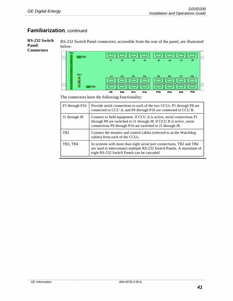
RS-232 Switch Panel: Connectors
RS-232 Switch Panel connectors, accessible from the rear of the panel, are illustrated below:
The connectors have the following functionality:
P1 through P16 Provide serial connections to each of the two CCUs. P1 through P8 are connected to CCU A, and P9 through P16 are connected to CCU B.
J1 through J8 Connect to field equipment. If CCU A is active, serial connections P1 through P8 are switched to J1 through J8. If CCU B is active, serial connections P9 through P16 are switched to J1 through J8.
TB1 Connect the monitor and control cables (referred to as the Watchdog cables) from each of the CCUs.
TB2, TB4 In systems with more than eight serial port connections, TB2 and TB4 are used to interconnect multiple RS-232 Switch Panels. A maximum of eight RS-232 Switch Panels can be cascaded.
D20/D200 Installation and Operations Guide GE Digital Energy
994-0078-2.00-9 GE Information
42
Connections and Configuration This Section Use this section to:
• Set external jumper configurations • Make field wiring connections
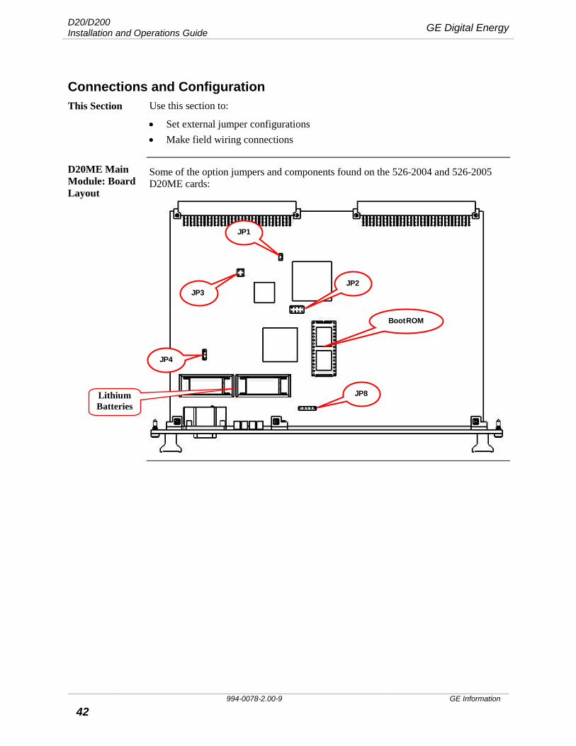
D20ME Main Module: Board Layout
Some of the option jumpers and components found on the 526-2004 and 526-2005 D20ME cards:
JP1
JP4
JP3 JP2
JP8
BootROM
Lithium Batteries
GE Digital Energy D20/D200 Installation and Operations Guide
GE Information 994-0078-2.00-9 43
Connections and Configuration, continued
D20ME Jumpering, continued
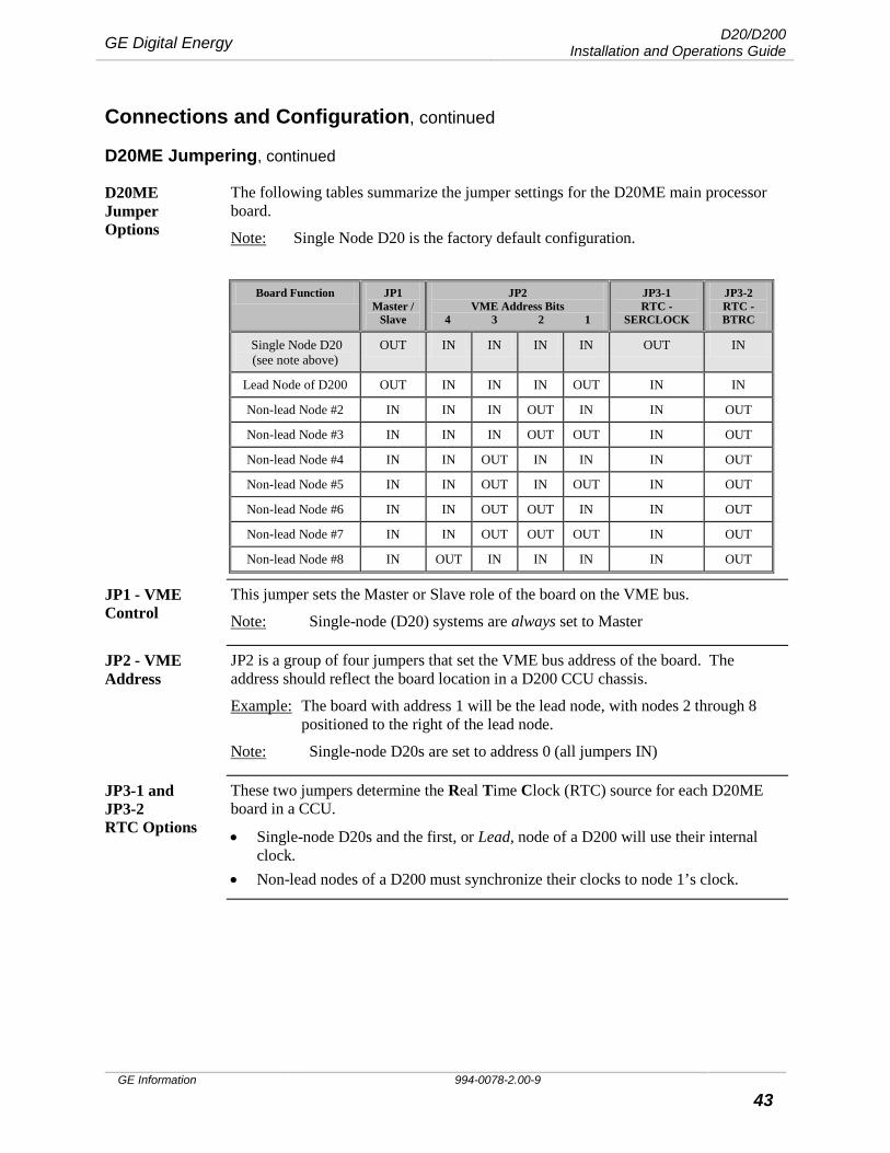
D20ME Jumper Options
The following tables summarize the jumper settings for the D20ME main processor board.
Note: Single Node D20 is the factory default configuration.
Board Function JP1 Master /
Slave
JP2 VME Address Bits
4 3 2 1
JP3-1 RTC -
SERCLOCK
JP3-2 RTC - BTRC
Single Node D20 (see note above)
OUT IN IN IN IN OUT IN
Lead Node of D200 OUT IN IN IN OUT IN IN
Non-lead Node #2 IN IN IN OUT IN IN OUT
Non-lead Node #3 IN IN IN OUT OUT IN OUT
Non-lead Node #4 IN IN OUT IN IN IN OUT
Non-lead Node #5 IN IN OUT IN OUT IN OUT
Non-lead Node #6 IN IN OUT OUT IN IN OUT
Non-lead Node #7 IN IN OUT OUT OUT IN OUT
Non-lead Node #8 IN OUT IN IN IN IN OUT
JP1 - VME Control
This jumper sets the Master or Slave role of the board on the VME bus.
Note: Single-node (D20) systems are always set to Master
JP2 - VME Address
JP2 is a group of four jumpers that set the VME bus address of the board. The address should reflect the board location in a D200 CCU chassis.
Example: The board with address 1 will be the lead node, with nodes 2 through 8 positioned to the right of the lead node.
Note: Single-node D20s are set to address 0 (all jumpers IN)
JP3-1 and JP3-2 RTC Options
These two jumpers determine the Real Time Clock (RTC) source for each D20ME board in a CCU.
• Single-node D20s and the first, or Lead, node of a D200 will use their internal clock.
• Non-lead nodes of a D200 must synchronize their clocks to node 1’s clock.

D20/D200 Installation and Operations Guide GE Digital Energy
994-0078-2.00-9 GE Information
44
Connections and Configuration, continued
D20ME Jumpering, continued
JP4 - Watchdog This 2-position jumper enables or disables the hardware Watchdog.
Note: The Watchdog should never be left disabled during normal operation of the D20ME.
JP4 Pins Jumper Position Function
Pin 1 = SLOWCK Pin 3 = /WD
pin 1 to 2 (center) disables the hardware Watchdog.
pin 3 to 2 (center) enables the hardware Watchdog.
JP8 – Battery Backup Enable/disable
The D20ME card has two 3.6V lithium batteries to maintain NVRAM contents in the event of a power failure.
Important: Disconnect the batteries if the board is to be stored for extended periods.
Jumper Position Function
JP8 pin 1 to 2 disconnects the batteries from the NVRAM
pin 3 to 2 connects the batteries to the NVRAM
pins 4 to 5 always jumpered
Other Jumpers Jumpers JP5, JP6 and JP7 are not user configurable. They are for factory test only.
GE Digital Energy D20/D200 Installation and Operations Guide
GE Information 994-0078-2.00-9 45
Connections and Configuration, continued
D20ME II Jumpering
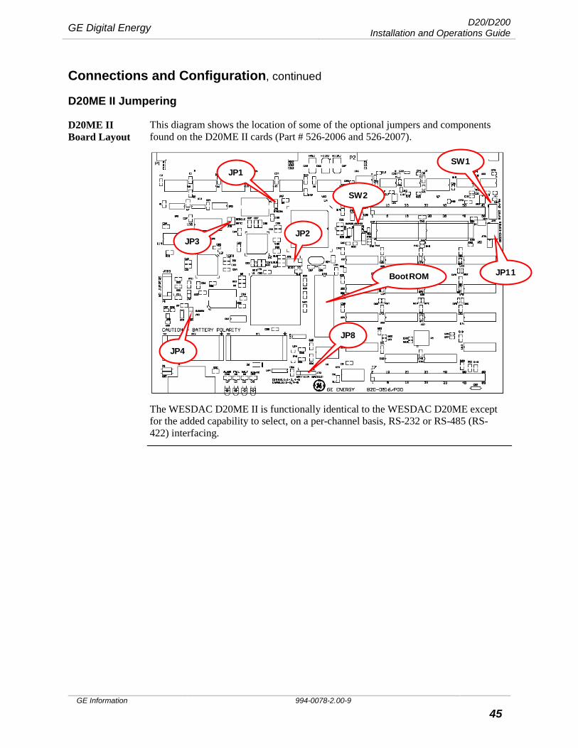
D20ME II Board Layout
This diagram shows the location of some of the optional jumpers and components found on the D20ME II cards (Part # 526-2006 and 526-2007).
The WESDAC D20ME II is functionally identical to the WESDAC D20ME except for the added capability to select, on a per-channel basis, RS-232 or RS-485 (RS-422) interfacing.
JP1
JP4
JP3 JP2
JP8
BootROM JP11
SW1
SW2

D20/D200 Installation and Operations Guide GE Digital Energy
994-0078-2.00-9 GE Information
46
Connections and Configuration, continued
D20ME II Jumpering, continued
Table: VME Jumper Options
The following tables summarize the jumper settings for each board function and position that is installed in a CCU for D20 or D200:
Single Node For D20 or D200:
Board Function JP1 Master /
Slave
JP2 VME Address Bits
4 3 2 1
JP3-1 RTC -
SERCLOCK
JP3-2 RTC - BRTC
Single Node OUT IN IN IN IN OUT IN
Multi-Node For D20 or D200:
Board Function JP1 Master /
Slave
JP2 VME Address Bits
4 3 2 1
JP3-1 RTC -
SERCLOCK
JP3-2 RTC - BRTC
Node #1 OUT IN IN IN OUT IN IN
Node #2 IN IN IN OUT IN IN OUT
Node #3 IN IN IN OUT OUT IN OUT
Node #4 IN IN OUT IN IN IN OUT
Node #5 IN IN OUT IN OUT IN OUT
Node #6 IN IN OUT OUT IN IN OUT
Node #7 IN IN OUT OUT OUT IN OUT
Node #8 IN OUT IN IN IN IN OUT
Notes: • Single Node is the factory default configuration.
• If you have a single-node implementation with Ethernet or Memory expansion or both, configure jumpers as Single Node.

GE Digital Energy D20/D200 Installation and Operations Guide
GE Information 994-0078-2.00-9 47
Connections and Configuration, continued
D20ME II Jumpering, continued
JP1 - VME Control
This jumper sets the Master or Slave function of the board on the VME bus.
Note: Single-node D20 systems are always set to Master.
JP2 - VME Address
JP2 is a group of four jumpers that set the VME bus address of the board. The address should reflect the board location in a D200 CCU chassis.
Example: The board with address 1 will be the lead node, with nodes 2 through 8 positioned to the right of the lead node.
Note: Single-node D20s are set to address 0 (all jumpers IN).
JP3-1 and JP3-2 RTC Options
These two jumpers determine the Real-Time Clock (RTC) source for each D20ME II board in a CCU:
• Single-node D20s and the first, or lead, node of a D200 both use an internal clock.
• Non-lead nodes of a D200 synchronize the clocks to the clock of the lead node.
Table: JP4 - Watchdog Enable/Disable
This two-position jumper enables or disables the hardware Watchdog.
Note: Never leave the Watchdog disabled during normal D20ME II operation.
Jumper Position Function
JP4
Pin 1 = SLOWCK Pin 3 = /WD
pin 1 to 2 (center)
Disables the hardware Watchdog.
pin 3 to 2 (center)
Enables the hardware Watchdog.
Table: JP8 – Battery Backup Enable/Disable
The D20ME II card has two 3.6V Lithium batteries, Tadiran® TL-2150 or equivalent, to maintain NVRAM contents in the event of a power failure.
Important: Disconnect the batteries if you are storing the board for extended periods of time.
Jumper Position Function
JP8 pin 1 to 2 Disconnects the batteries from the NVRAM
pin 3 to 2 Connects the batteries to the NVRAM
pins 4 to 5 Always jumpered

D20/D200 Installation and Operations Guide GE Digital Energy
994-0078-2.00-9 GE Information
48
Connections and Configuration, continued
D20ME II Jumpering, continued
SW1
RS-485 2W/4W
When set for RS-485 mode (see SW2), each serial communication port channel must be set for either RS-485 2-wire with the switch ON, or RS-485 4-wire (RS422) with the switch OFF. RS-232 is the factory default setting for the D20ME Processor with the switch OFF.
Note: In order for RS485 (2-wire/4-wire) to operate, the RTS ON/OFF setting must be enabled and both DCD and CTS must be disabled in Config Pro specific to the protocol being used for that serial port. RTS must be toggled ON for RS485 2-wire transmissions and may be set continuously ON for RS485 4-wire data transmissions.
Note: When operating a serial communication channel in RS-232 mode always have the corresponding switch OFF.
SW1 (pins) Serial Comm Port RS-485 2-wire
RS-485 4-wire
RS-232
1-16 1 ON OFF OFF
2-15 2 ON OFF OFF
3-14 3 ON OFF OFF
4-13 4 ON OFF OFF
5-12 5 ON OFF OFF
6-11 6 ON OFF OFF
7-10 7 ON OFF OFF
SW2
RS-485/RS-232 Mode Selection
SW2 allows each serial communication port channel to be set for either RS-485 (RS-422) mode with the switch ON, or for the default setting of RS-232 mode with the switch OFF.
JP10 (pins) Serial Comm Port RS-485(RS-422) mode
RS-232 mode
1-16 1 ON OFF
2-15 2 ON OFF
3-14 3 ON OFF
4-13 4 ON OFF
5-12 5 ON OFF
6-11 6 ON OFF
7-10 7 ON OFF
GE Digital Energy D20/D200 Installation and Operations Guide
GE Information 994-0078-2.00-9 49
Connections and Configuration, continued
D20ME II Jumpering, continued
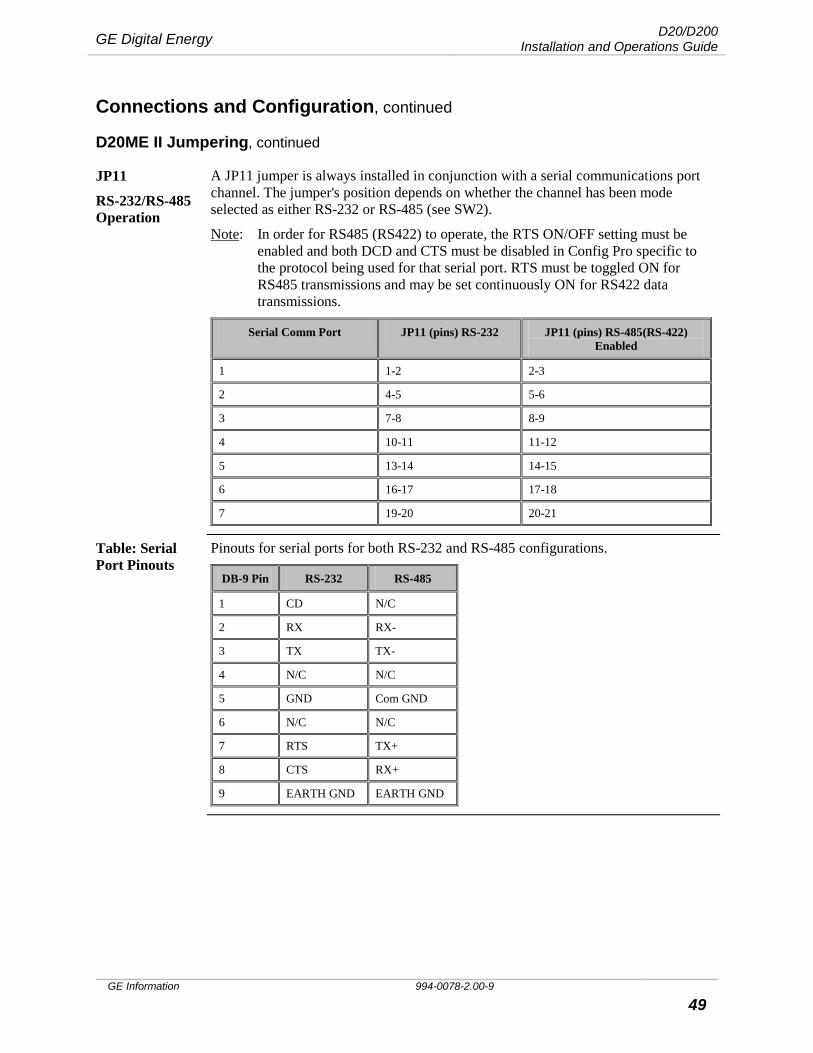
JP11
RS-232/RS-485 Operation
A JP11 jumper is always installed in conjunction with a serial communications port channel. The jumper's position depends on whether the channel has been mode selected as either RS-232 or RS-485 (see SW2).
Note: In order for RS485 (RS422) to operate, the RTS ON/OFF setting must be enabled and both DCD and CTS must be disabled in Config Pro specific to the protocol being used for that serial port. RTS must be toggled ON for RS485 transmissions and may be set continuously ON for RS422 data transmissions.
Serial Comm Port JP11 (pins) RS-232 JP11 (pins) RS-485(RS-422) Enabled
1 1-2 2-3
2 4-5 5-6
3 7-8 8-9
4 10-11 11-12
5 13-14 14-15
6 16-17 17-18
7 19-20 20-21
Table: Serial Port Pinouts
Pinouts for serial ports for both RS-232 and RS-485 configurations.
DB-9 Pin RS-232 RS-485
1 CD N/C
2 RX RX-
3 TX TX-
4 N/C N/C
5 GND Com GND
6 N/C N/C
7 RTS TX+
8 CTS RX+
9 EARTH GND EARTH GND
D20/D200 Installation and Operations Guide GE Digital Energy
994-0078-2.00-9 GE Information
50
Connections and Configuration, continued
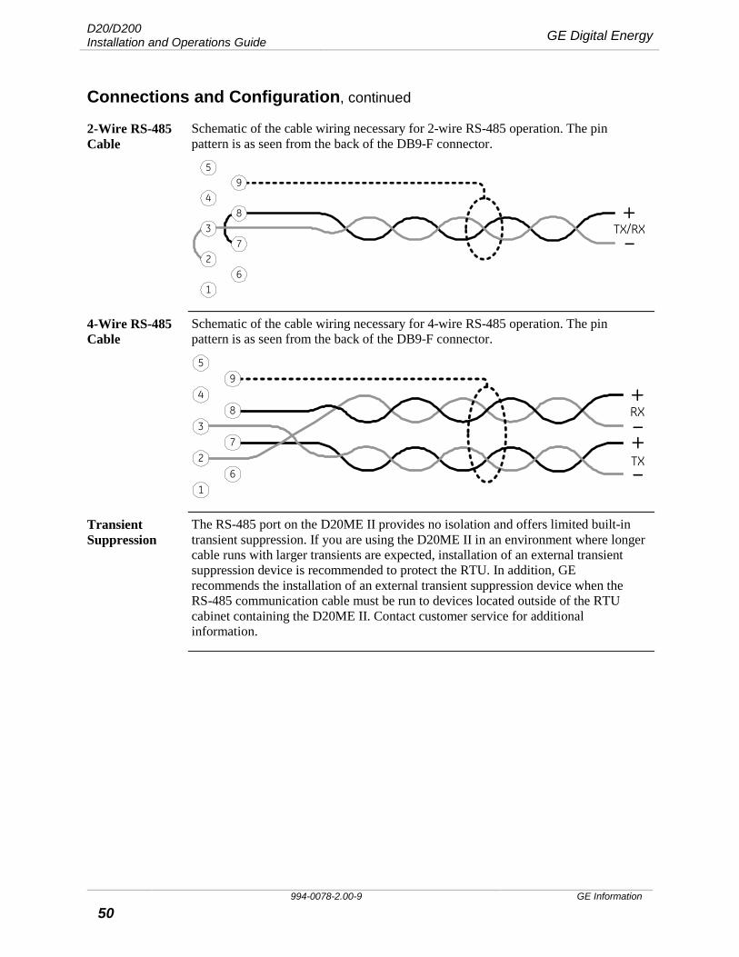
2-Wire RS-485 Cable
Schematic of the cable wiring necessary for 2-wire RS-485 operation. The pin pattern is as seen from the back of the DB9-F connector.
59
4
72
61
+–
TX/RX38
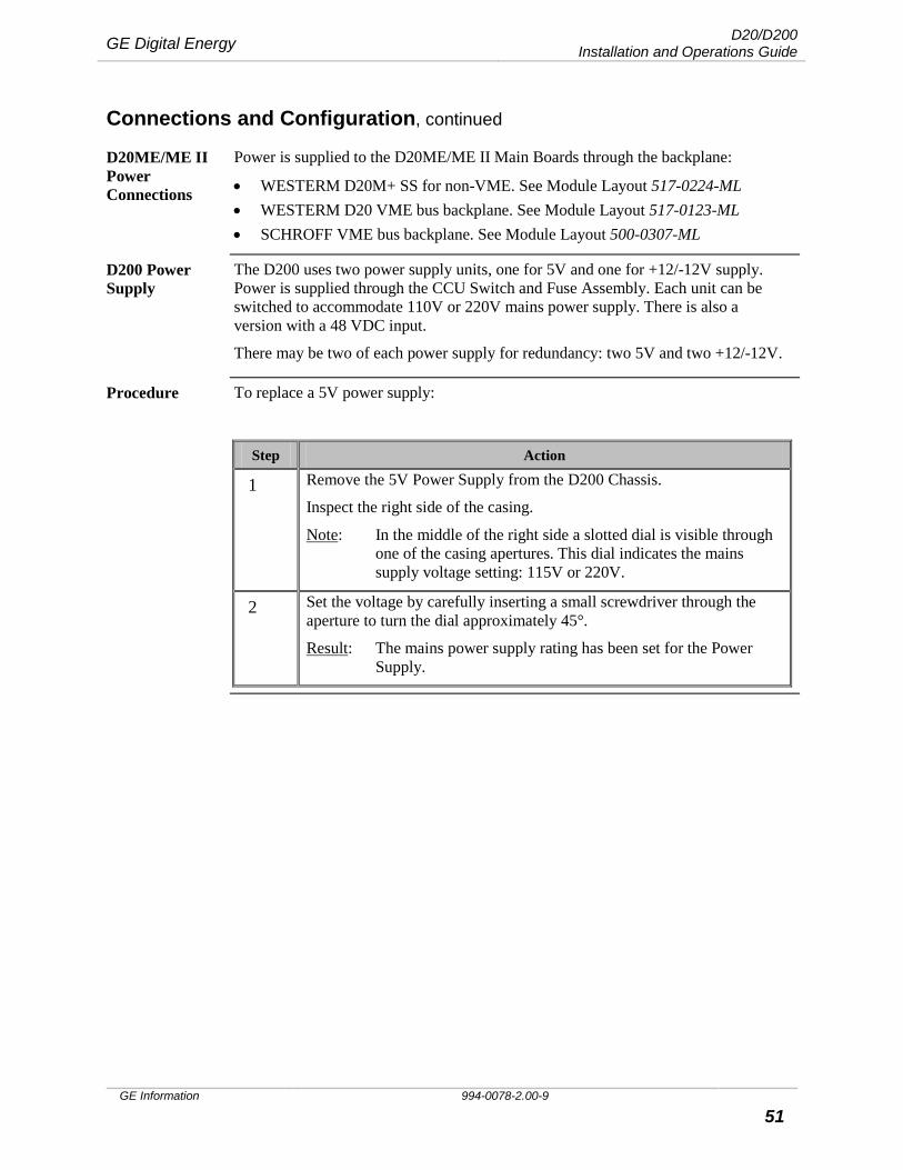
4-Wire RS-485 Cable
Schematic of the cable wiring necessary for 4-wire RS-485 operation. The pin pattern is as seen from the back of the DB9-F connector.
59
4
37
61
+
+–
–8
2
RX
TX
Transient Suppression
The RS-485 port on the D20ME II provides no isolation and offers limited built-in transient suppression. If you are using the D20ME II in an environment where longer cable runs with larger transients are expected, installation of an external transient suppression device is recommended to protect the RTU. In addition, GE recommends the installation of an external transient suppression device when the RS-485 communication cable must be run to devices located outside of the RTU cabinet containing the D20ME II. Contact customer service for additional information.
GE Digital Energy D20/D200 Installation and Operations Guide
GE Information 994-0078-2.00-9 51
Connections and Configuration, continued
D20ME/ME II Power Connections
Power is supplied to the D20ME/ME II Main Boards through the backplane:
• WESTERM D20M+ SS for non-VME. See Module Layout 517-0224-ML • WESTERM D20 VME bus backplane. See Module Layout 517-0123-ML • SCHROFF VME bus backplane. See Module Layout 500-0307-ML
D200 Power Supply
The D200 uses two power supply units, one for 5V and one for +12/-12V supply. Power is supplied through the CCU Switch and Fuse Assembly. Each unit can be switched to accommodate 110V or 220V mains power supply. There is also a version with a 48 VDC input.
There may be two of each power supply for redundancy: two 5V and two +12/-12V.
Procedure To replace a 5V power supply:
Step Action
1 Remove the 5V Power Supply from the D200 Chassis.
Inspect the right side of the casing.
Note: In the middle of the right side a slotted dial is visible through one of the casing apertures. This dial indicates the mains supply voltage setting: 115V or 220V.
2 Set the voltage by carefully inserting a small screwdriver through the aperture to turn the dial approximately 45°.
Result: The mains power supply rating has been set for the Power Supply.
D20/D200 Installation and Operations Guide GE Digital Energy
994-0078-2.00-9 GE Information
52
Connections and Configuration, continued
Procedure To switch +12/-12V power supply:
Step Action
1 Remove the +12/-12V Power Supply from the D200 Chassis.
Inspect the right side of the casing.
Note: In the middle at the bottom of the right side a toggle switch is visible through one of the casing apertures. This switch indicates the mains supply voltage setting: 220V/110V.
2 Set the voltage as required by carefully toggling the switch through an aperture in the underside of the casing.
Result: The mains power supply rating has been set for the Power Supply.
GE Digital Energy D20/D200 Installation and Operations Guide
GE Information 994-0078-2.00-9 53
Connections and Configuration, continued
Termination Panels: Jumper Settings
There are three WESTERM Termination Panels. For jumper configuration settings for each of these boards see the Module Layout drawings:
• WESTERM D20M+ SS for non-VME see 517-0224-ML • WESTERM D20M+ for VME see 517-0225-ML • WESTERM D20M++ for VME see 517-0245-ML
Termination Panels: Power Supply
Power connections to the WESTERM Termination Panels are made on connector blocks:
• TB1 on the WESTERM D20M+ SS and WESTERM D20M+ • TB2 on the WESTERM D20M++
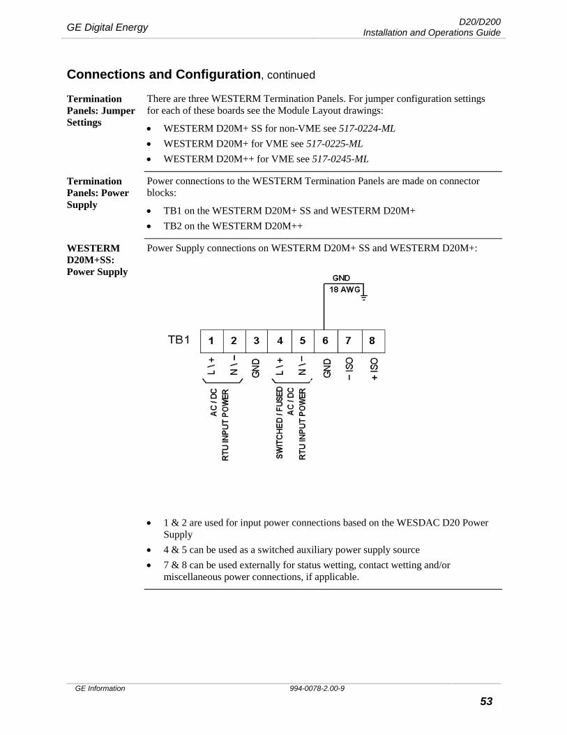
WESTERM D20M+SS: Power Supply
Power Supply connections on WESTERM D20M+ SS and WESTERM D20M+:
• 1 & 2 are used for input power connections based on the WESDAC D20 Power
Supply • 4 & 5 can be used as a switched auxiliary power supply source • 7 & 8 can be used externally for status wetting, contact wetting and/or
miscellaneous power connections, if applicable.
D20/D200 Installation and Operations Guide GE Digital Energy
994-0078-2.00-9 GE Information
54
Connections and Configuration, continued
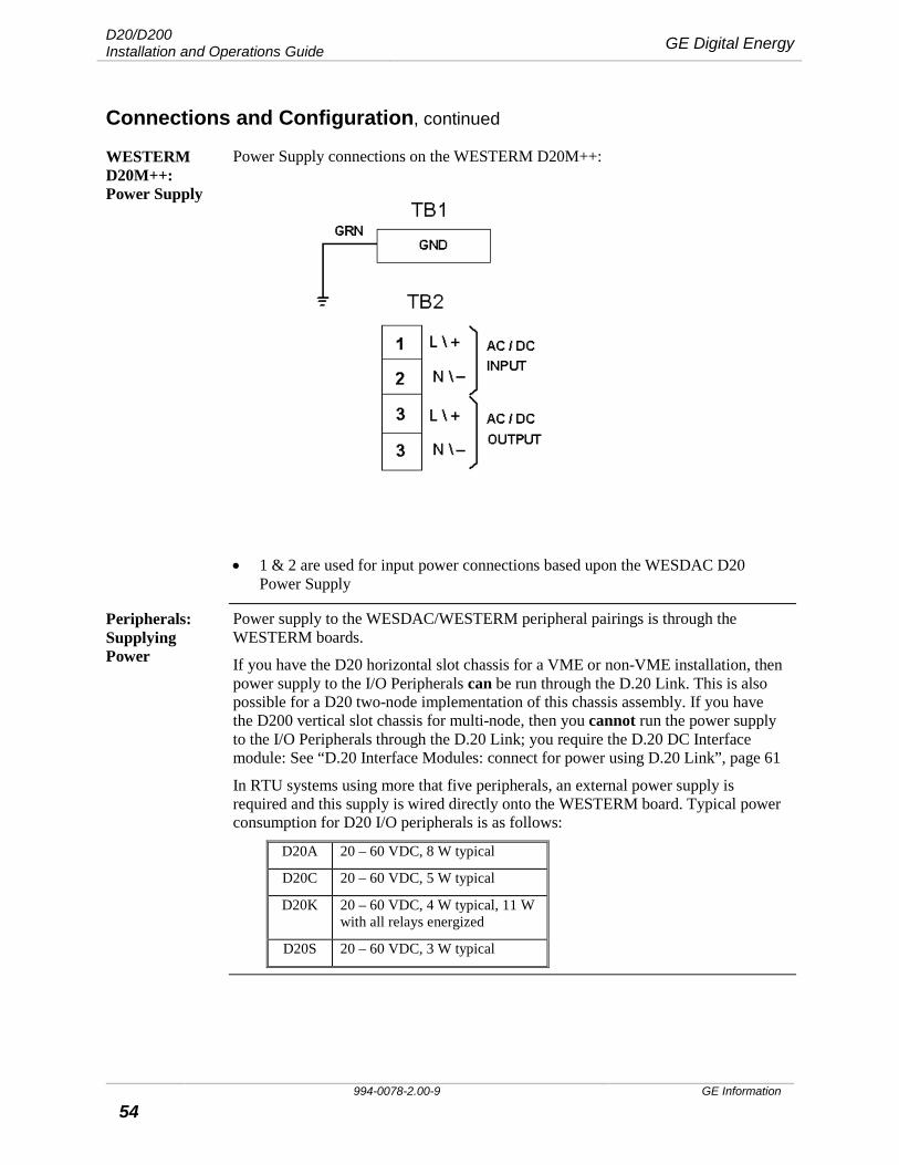
WESTERM D20M++: Power Supply
Power Supply connections on the WESTERM D20M++:
• 1 & 2 are used for input power connections based upon the WESDAC D20
Power Supply
Peripherals: Supplying Power
Power supply to the WESDAC/WESTERM peripheral pairings is through the WESTERM boards.
If you have the D20 horizontal slot chassis for a VME or non-VME installation, then power supply to the I/O Peripherals can be run through the D.20 Link. This is also possible for a D20 two-node implementation of this chassis assembly. If you have the D200 vertical slot chassis for multi-node, then you cannot run the power supply to the I/O Peripherals through the D.20 Link; you require the D.20 DC Interface module: See “D.20 Interface Modules: connect for power using D.20 Link”, page 61
In RTU systems using more that five peripherals, an external power supply is required and this supply is wired directly onto the WESTERM board. Typical power consumption for D20 I/O peripherals is as follows:
D20A 20 – 60 VDC, 8 W typical
D20C 20 – 60 VDC, 5 W typical
D20K 20 – 60 VDC, 4 W typical, 11 W with all relays energized
D20S 20 – 60 VDC, 3 W typical
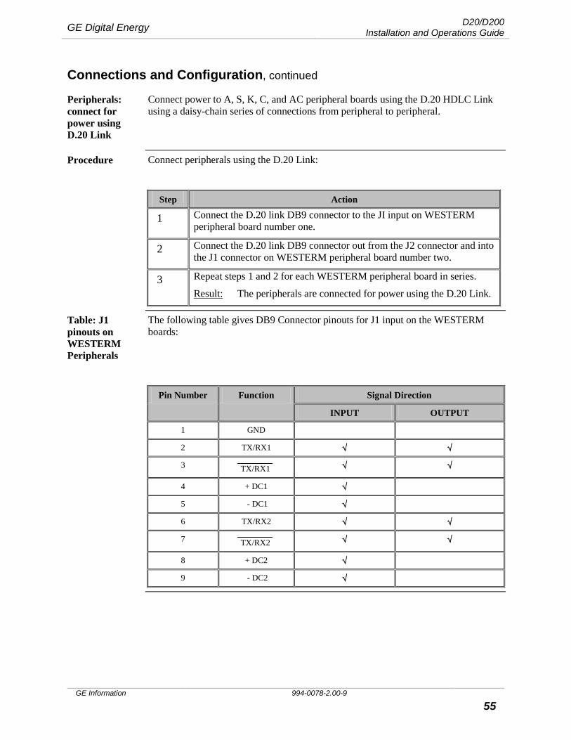
GE Digital Energy D20/D200 Installation and Operations Guide
GE Information 994-0078-2.00-9 55
Connections and Configuration, continued
Peripherals: connect for power using D.20 Link
Connect power to A, S, K, C, and AC peripheral boards using the D.20 HDLC Link using a daisy-chain series of connections from peripheral to peripheral.
Procedure Connect peripherals using the D.20 Link:
Step Action
1 Connect the D.20 link DB9 connector to the JI input on WESTERM peripheral board number one.
2 Connect the D.20 link DB9 connector out from the J2 connector and into the J1 connector on WESTERM peripheral board number two.
3 Repeat steps 1 and 2 for each WESTERM peripheral board in series.
Result: The peripherals are connected for power using the D.20 Link.
Table: J1 pinouts on WESTERM Peripherals
The following table gives DB9 Connector pinouts for J1 input on the WESTERM boards:
Pin Number Function Signal Direction
INPUT OUTPUT
1 GND
2 TX/RX1 √ √
3 TX/RX1 √ √
4 + DC1 √
5 - DC1 √
6 TX/RX2 √ √
7 TX/RX2 √ √
8 + DC2 √
9 - DC2 √

D20/D200 Installation and Operations Guide GE Digital Energy
994-0078-2.00-9 GE Information
56
Connections and Configuration, continued
WESTERM D20A: External Loop Supply
For connections to an external power supply for current loop powered transducers, use TB1-49 and TB1-99 on the WESTERM D20A:
Jumpers Z3 and Z4 must be set for loop supply routing. Fuse F2 provides overcurrent protection on the positive leg of the selected loop supply. See “WESTERM D20A: Jumpers”, page 66.
WESTERM D20S: External DC Supply
For connections to an external DC power source for status input wetting, use TB1-65 and TB1-131 on the WESTERM D20S:
Jumpers Z2 and Z3 must be set for external supply source. Since bipolar status inputs are allowed, the polarity of the external supply can be connected either way, depending on the application. Fuses F2 and F3 provide fusing on each leg of the supply. See “WESTERM D20S: Jumpers”, page 67.
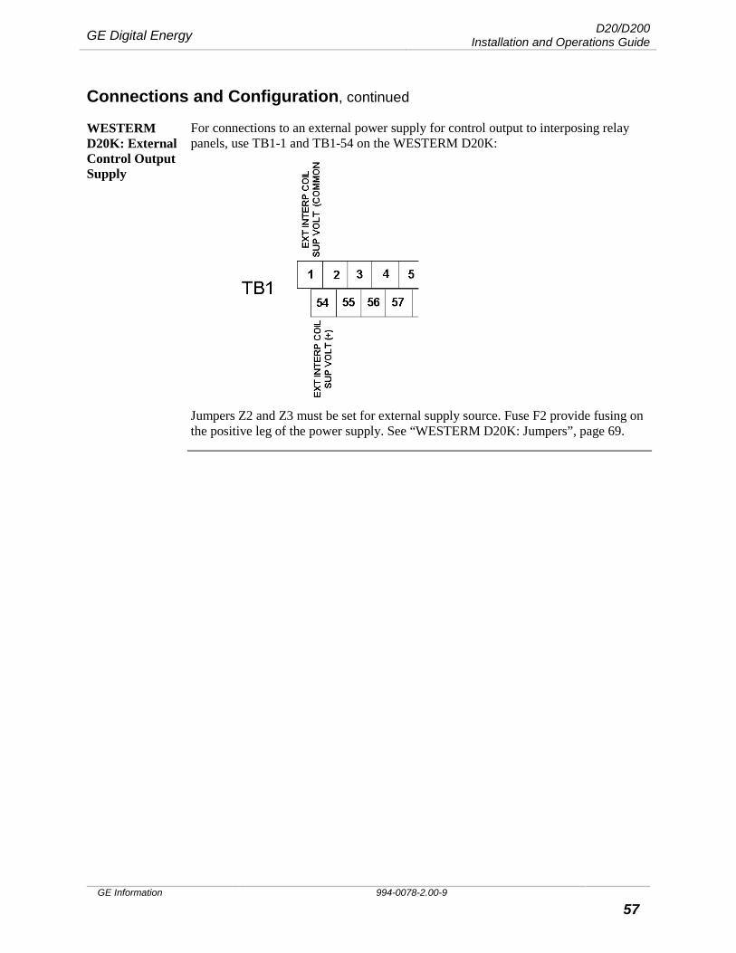
GE Digital Energy D20/D200 Installation and Operations Guide
GE Information 994-0078-2.00-9 57
Connections and Configuration, continued
WESTERM D20K: External Control Output Supply
For connections to an external power supply for control output to interposing relay panels, use TB1-1 and TB1-54 on the WESTERM D20K:
Jumpers Z2 and Z3 must be set for external supply source. Fuse F2 provide fusing on the positive leg of the power supply. See “WESTERM D20K: Jumpers”, page 69.
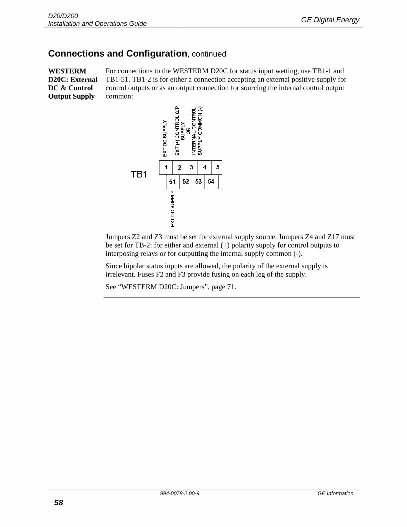
D20/D200 Installation and Operations Guide GE Digital Energy
994-0078-2.00-9 GE Information
58
Connections and Configuration, continued
WESTERM D20C: External DC & Control Output Supply
For connections to the WESTERM D20C for status input wetting, use TB1-1 and TB1-51. TB1-2 is for either a connection accepting an external positive supply for control outputs or as an output connection for sourcing the internal control output common:
Jumpers Z2 and Z3 must be set for external supply source. Jumpers Z4 and Z17 must be set for TB-2: for either and external (+) polarity supply for control outputs to interposing relays or for outputting the internal supply common (-).
Since bipolar status inputs are allowed, the polarity of the external supply is irrelevant. Fuses F2 and F3 provide fusing on each leg of the supply.
See “WESTERM D20C: Jumpers”, page 71.
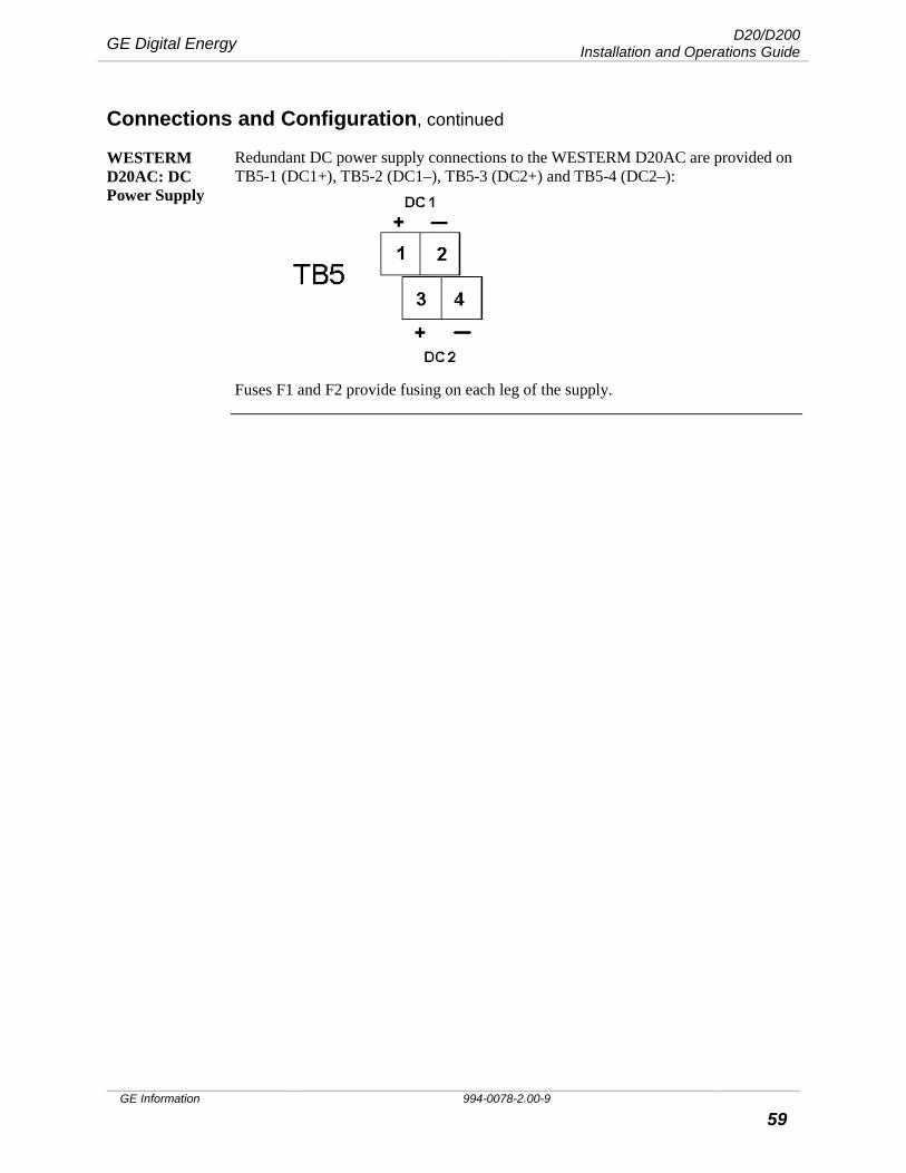
GE Digital Energy D20/D200 Installation and Operations Guide
GE Information 994-0078-2.00-9 59
Connections and Configuration, continued
WESTERM D20AC: DC Power Supply
Redundant DC power supply connections to the WESTERM D20AC are provided on TB5-1 (DC1+), TB5-2 (DC1–), TB5-3 (DC2+) and TB5-4 (DC2–):
Fuses F1 and F2 provide fusing on each leg of the supply.
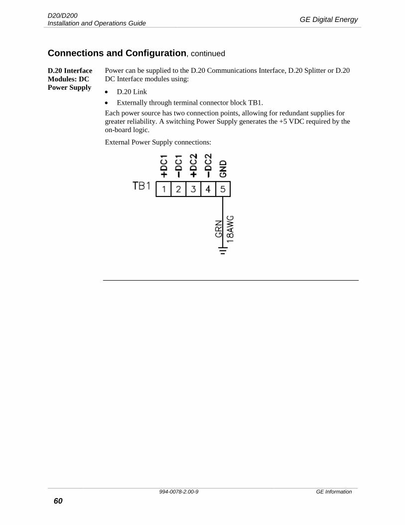
D20/D200 Installation and Operations Guide GE Digital Energy
994-0078-2.00-9 GE Information
60
Connections and Configuration, continued
D.20 Interface Modules: DC Power Supply
Power can be supplied to the D.20 Communications Interface, D.20 Splitter or D.20 DC Interface modules using:
• D.20 Link • Externally through terminal connector block TB1. Each power source has two connection points, allowing for redundant supplies for greater reliability. A switching Power Supply generates the +5 VDC required by the on-board logic.
External Power Supply connections:
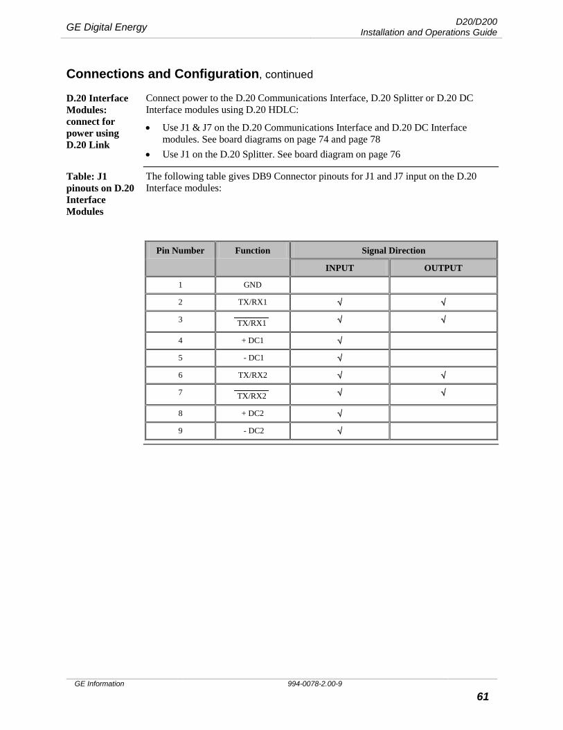
GE Digital Energy D20/D200 Installation and Operations Guide
GE Information 994-0078-2.00-9 61
Connections and Configuration, continued
D.20 Interface Modules: connect for power using D.20 Link
Connect power to the D.20 Communications Interface, D.20 Splitter or D.20 DC Interface modules using D.20 HDLC:
• Use J1 & J7 on the D.20 Communications Interface and D.20 DC Interface modules. See board diagrams on page 74 and page 78
• Use J1 on the D.20 Splitter. See board diagram on page 76
Table: J1 pinouts on D.20 Interface Modules
The following table gives DB9 Connector pinouts for J1 and J7 input on the D.20 Interface modules:
Pin Number Function Signal Direction
INPUT OUTPUT
1 GND
2 TX/RX1 √ √
3 TX/RX1 √ √
4 + DC1 √
5 - DC1 √
6 TX/RX2 √ √
7 TX/RX2 √ √
8 + DC2 √
9 - DC2 √
D20/D200 Installation and Operations Guide GE Digital Energy
994-0078-2.00-9 GE Information
62
Connections and Configuration, continued
I/O Peripheral Boards: Jumper Settings
Jumper location and configuration settings are given below. You can also refer to the Module Layouts for these boards:
• D20A Analog Input − WESDAC D20A see 511-0101-ML − WESTERM D20A see 517-0163-ML
• D20S Digital Input − WESDAC D20S see 507-0101-ML − WESTERM D20S see 517-0165-ML
• D20K Control Output − WESDAC D20K see 508-0101-ML − WESTERM D20K see 517-0164-ML
• D20C Combination I/O − WESDAC D20C see 504-0002-ML − WESTERM D20C see 517-0169-ML
• D20AC (Alternating Current) Analog Input − WESDAC D20AC see 511-0104-ML for 40 – 150V power and 511-0106-ML
for 20 – 60V power
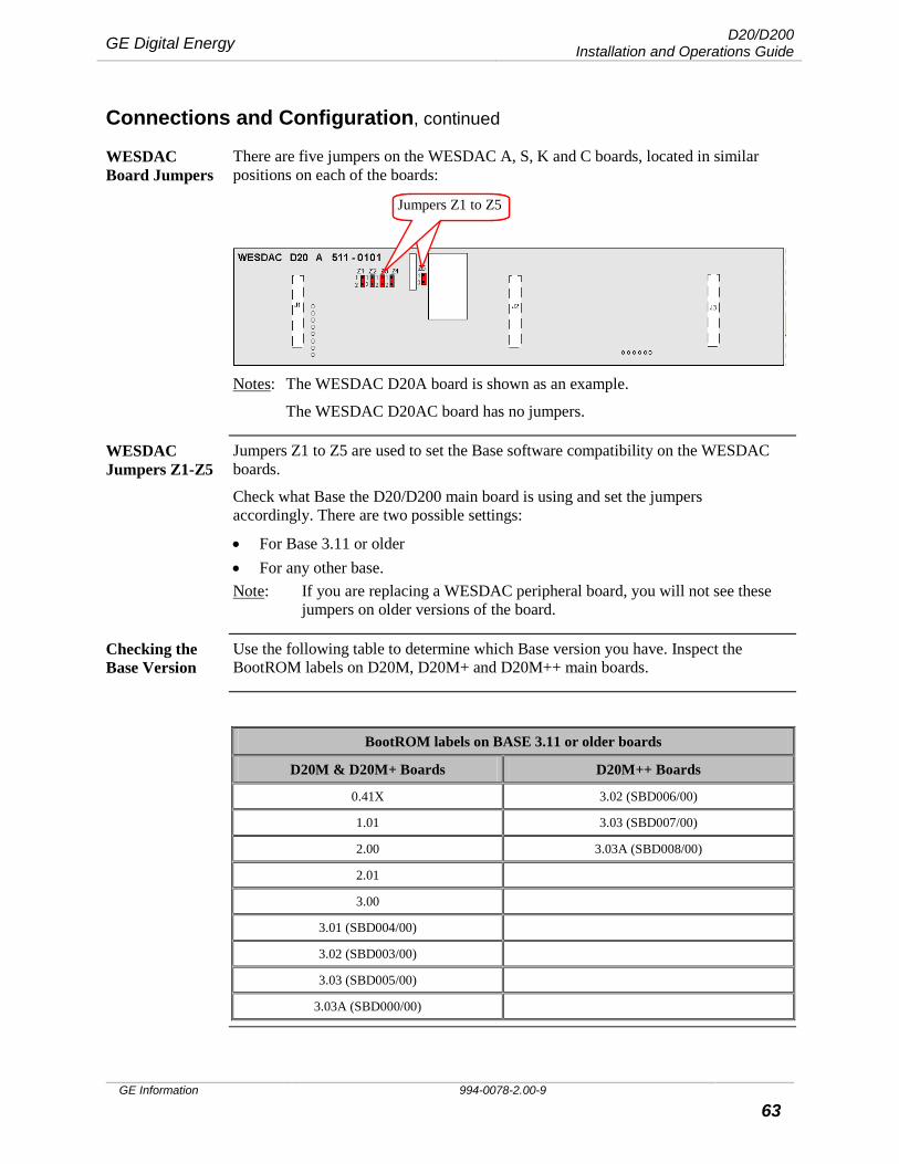
GE Digital Energy D20/D200 Installation and Operations Guide
GE Information 994-0078-2.00-9 63
Connections and Configuration, continued
WESDAC Board Jumpers
There are five jumpers on the WESDAC A, S, K and C boards, located in similar positions on each of the boards:
Notes: The WESDAC D20A board is shown as an example.
The WESDAC D20AC board has no jumpers.
WESDAC Jumpers Z1-Z5
Jumpers Z1 to Z5 are used to set the Base software compatibility on the WESDAC boards.
Check what Base the D20/D200 main board is using and set the jumpers accordingly. There are two possible settings:
• For Base 3.11 or older • For any other base. Note: If you are replacing a WESDAC peripheral board, you will not see these
jumpers on older versions of the board.
Checking the Base Version
Use the following table to determine which Base version you have. Inspect the BootROM labels on D20M, D20M+ and D20M++ main boards.
BootROM labels on BASE 3.11 or older boards
D20M & D20M+ Boards D20M++ Boards
0.41X 3.02 (SBD006/00)
1.01 3.03 (SBD007/00)
2.00 3.03A (SBD008/00)
2.01
3.00
3.01 (SBD004/00)
3.02 (SBD003/00)
3.03 (SBD005/00)
3.03A (SBD000/00)
Jumpers Z1 to Z5 Jumpers Z1 to Z5
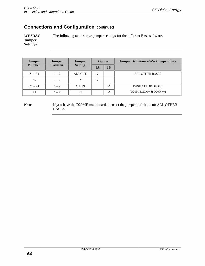
D20/D200 Installation and Operations Guide GE Digital Energy
994-0078-2.00-9 GE Information
64
Connections and Configuration, continued
WESDAC Jumper Settings
The following table shows jumper settings for the different Base software.
Jumper Number
Jumper Position
Jumper Setting
Option Jumper Definition – S/W Compatibility
1A 1B
Z1 – Z4 1 – 2 ALL OUT √ ALL OTHER BASES
Z5 1 – 2 IN √
Z1 – Z4 1 – 2 ALL IN √ BASE 3.11 OR OLDER
(D20M, D20M+ & D20M++) Z5 1 – 2 IN √
Note If you have the D20ME main board, then set the jumper definition to: ALL OTHER
BASES.
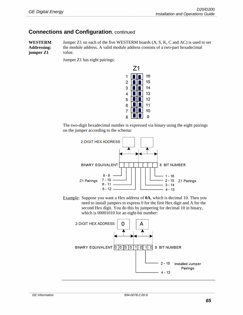
GE Digital Energy D20/D200 Installation and Operations Guide
GE Information 994-0078-2.00-9 65
Connections and Configuration, continued
WESTERM Addressing: jumper Z1
Jumper Z1 on each of the five WESTERM boards (A, S, K, C and AC) is used to set the module address. A valid module address consists of a two-part hexadecimal value.
Jumper Z1 has eight pairings:
The two-digit hexadecimal number is expressed via binary using the eight pairings on the jumper according to the schema:
Example: Suppose you want a Hex address of 0A, which is decimal 10. Then you
need to install jumpers to express 0 for the first Hex digit and A for the second Hex digit. You do this by jumpering for decimal 10 in binary, which is 00001010 for an eight-bit number:

D20/D200 Installation and Operations Guide GE Digital Energy
994-0078-2.00-9 GE Information
66
Connections and Configuration, continued
WESTERM D20A: Jumpers
Jumper locations on the WESTERM D20A:
To set Module address jumpering on Z1, see “WESTERM Addressing”, page 65.
Use jumpers:
• Z2 to enable/disable low loop supply voltage sensing • Z3 and Z4 to set Analog loop supply.
WESTERM D20A: Jumper Settings
The following table gives jumper settings for Z2, Z3 and Z4.
Jumper Number
Jumper Position
Jumper Setting
Option 1 Jumper Definition – Low Loop Supply
1A 1B
Z2 1 – 2 IN √ Enable bypass for low loop supply sensing
1 – 2 OUT √ Disable bypass for low loop supply sensing
Option 2 Jumper Definition – Analog Loop Supply
2A 2B 2C
Z3 & Z4 1 – 2 IN √ Internal Analog loop supply provided by DC1 or DC2
2 – 3 IN √ External Analog loop supply on TB1-1 & 3
1 – 2 & 2 – 3 OUT √ Not required
Z1
Z2
Z3
Z4
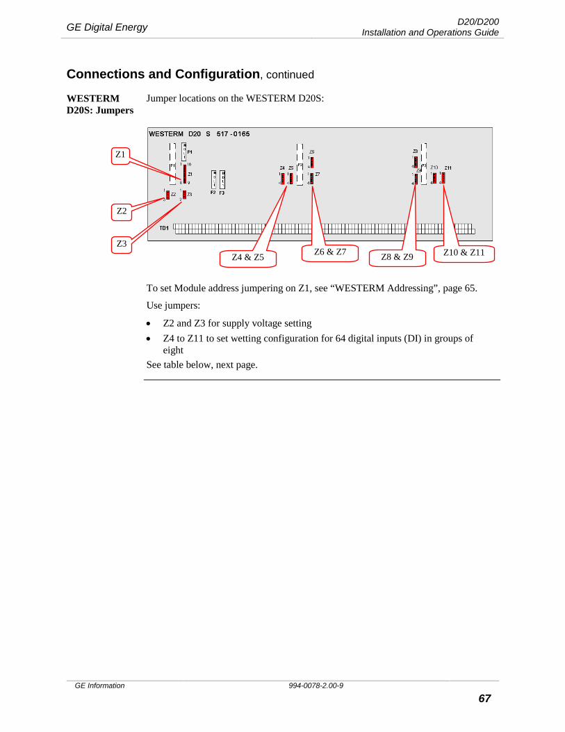
GE Digital Energy D20/D200 Installation and Operations Guide
GE Information 994-0078-2.00-9 67
Connections and Configuration, continued
WESTERM D20S: Jumpers
Jumper locations on the WESTERM D20S:
To set Module address jumpering on Z1, see “WESTERM Addressing”, page 65.
Use jumpers:
• Z2 and Z3 for supply voltage setting • Z4 to Z11 to set wetting configuration for 64 digital inputs (DI) in groups of
eight See table below, next page.
Z1
Z2
Z3 Z4 & Z5 Z6 & Z7 Z8 & Z9 Z10 & Z11
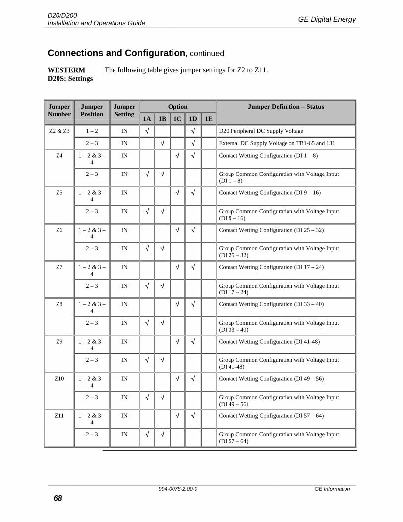
D20/D200 Installation and Operations Guide GE Digital Energy
994-0078-2.00-9 GE Information
68
Connections and Configuration, continued
WESTERM D20S: Settings
The following table gives jumper settings for Z2 to Z11.
Jumper Number
Jumper Position
Jumper Setting
Option Jumper Definition – Status
1A 1B 1C 1D 1E
Z2 & Z3 1 – 2 IN √ √ D20 Peripheral DC Supply Voltage
2 – 3 IN √ √ External DC Supply Voltage on TB1-65 and 131
Z4 1 – 2 & 3 – 4
IN √ √ Contact Wetting Configuration (DI 1 – 8)
2 – 3 IN √ √ Group Common Configuration with Voltage Input (DI 1 – 8)
Z5 1 – 2 & 3 – 4
IN √ √ Contact Wetting Configuration (DI 9 – 16)
2 – 3 IN √ √ Group Common Configuration with Voltage Input (DI 9 – 16)
Z6 1 – 2 & 3 – 4
IN √ √ Contact Wetting Configuration (DI 25 – 32)
2 – 3 IN √ √ Group Common Configuration with Voltage Input (DI 25 – 32)
Z7 1 – 2 & 3 – 4
IN √ √ Contact Wetting Configuration (DI 17 – 24)
2 – 3 IN √ √ Group Common Configuration with Voltage Input (DI 17 – 24)
Z8 1 – 2 & 3 – 4
IN √ √ Contact Wetting Configuration (DI 33 – 40)
2 – 3 IN √ √ Group Common Configuration with Voltage Input (DI 33 – 40)
Z9 1 – 2 & 3 – 4
IN √ √ Contact Wetting Configuration (DI 41-48)
2 – 3 IN √ √ Group Common Configuration with Voltage Input (DI 41-48)
Z10 1 – 2 & 3 – 4
IN √ √ Contact Wetting Configuration (DI 49 – 56)
2 – 3 IN √ √ Group Common Configuration with Voltage Input (DI 49 – 56)
Z11 1 – 2 & 3 – 4
IN √ √ Contact Wetting Configuration (DI 57 – 64)
2 – 3 IN √ √ Group Common Configuration with Voltage Input (DI 57 – 64)
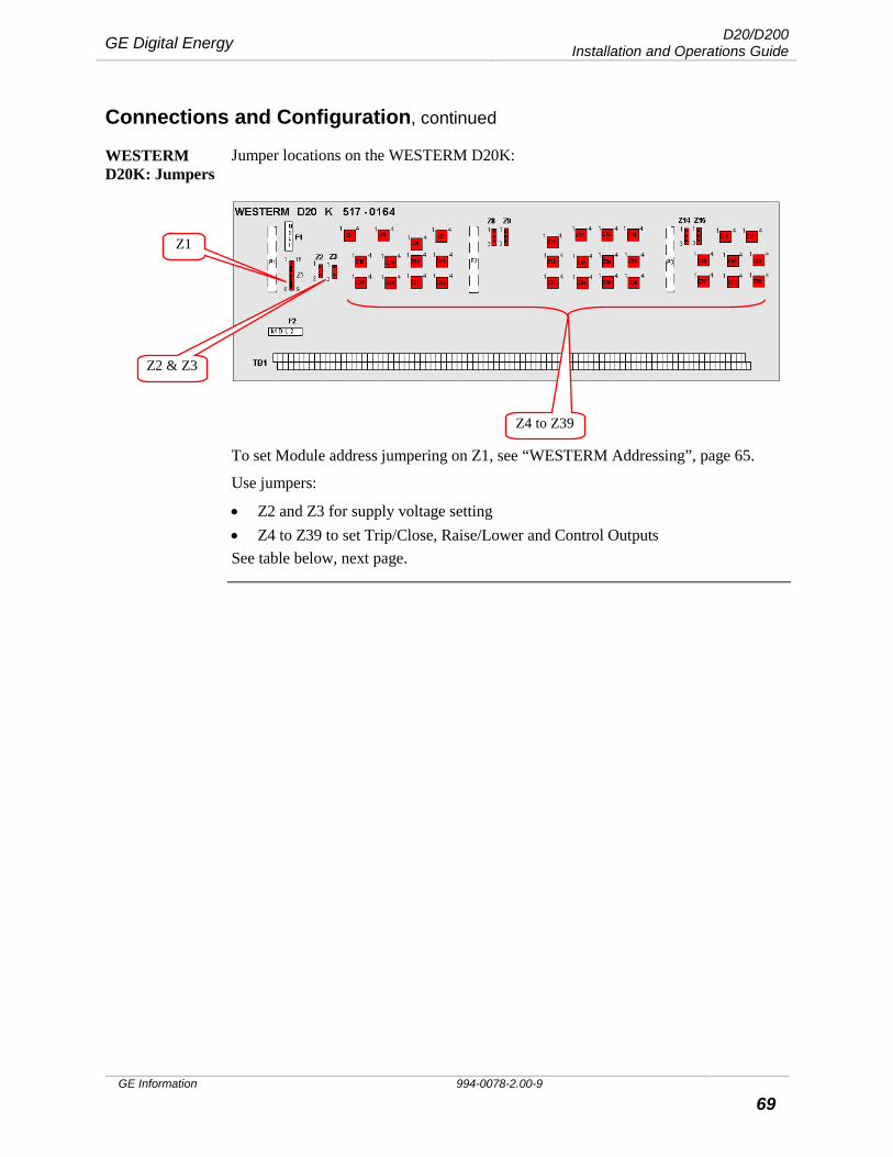
GE Digital Energy D20/D200 Installation and Operations Guide
GE Information 994-0078-2.00-9 69
Connections and Configuration, continued
WESTERM D20K: Jumpers
Jumper locations on the WESTERM D20K:
To set Module address jumpering on Z1, see “WESTERM Addressing”, page 65.
Use jumpers:
• Z2 and Z3 for supply voltage setting • Z4 to Z39 to set Trip/Close, Raise/Lower and Control Outputs See table below, next page.
Z1
Z2 & Z3
Z4 to Z39
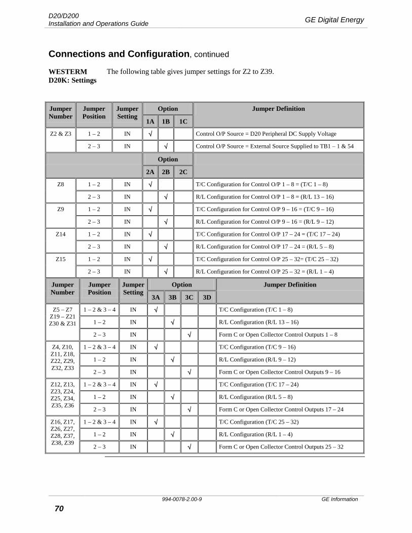
D20/D200 Installation and Operations Guide GE Digital Energy
994-0078-2.00-9 GE Information
70
Connections and Configuration, continued
WESTERM D20K: Settings
The following table gives jumper settings for Z2 to Z39.
Jumper Number
Jumper Position
Jumper Setting
Option Jumper Definition
1A 1B 1C
Z2 & Z3 1 – 2 IN √ Control O/P Source = D20 Peripheral DC Supply Voltage
2 – 3 IN √ Control O/P Source = External Source Supplied to TB1 – 1 & 54
Option
2A 2B 2C
Z8 1 – 2 IN √ T/C Configuration for Control O/P 1 – 8 = (T/C 1 – 8)
2 – 3 IN √ R/L Configuration for Control O/P 1 – 8 = (R/L 13 – 16)
Z9 1 – 2 IN √ T/C Configuration for Control O/P 9 – 16 = (T/C 9 – 16)
2 – 3 IN √ R/L Configuration for Control O/P 9 – 16 = (R/L 9 – 12)
Z14 1 – 2 IN √ T/C Configuration for Control O/P 17 – 24 = (T/C 17 – 24)
2 – 3 IN √ R/L Configuration for Control O/P 17 – 24 = (R/L 5 – 8)
Z15 1 – 2 IN √ T/C Configuration for Control O/P 25 – 32= (T/C 25 – 32)
2 – 3 IN √ R/L Configuration for Control O/P 25 – 32 = (R/L 1 – 4)
Jumper Number
Jumper Position
Jumper Setting
Option Jumper Definition
3A 3B 3C 3D
Z5 – Z7 Z19 – Z21 Z30 & Z31
1 – 2 & 3 – 4 IN √ T/C Configuration (T/C 1 – 8)
1 – 2 IN √ R/L Configuration (R/L 13 – 16)
2 – 3 IN √ Form C or Open Collector Control Outputs 1 – 8
Z4, Z10, Z11, Z18, Z22, Z29, Z32, Z33
1 – 2 & 3 – 4 IN √ T/C Configuration (T/C 9 – 16)
1 – 2 IN √ R/L Configuration (R/L 9 – 12)
2 – 3 IN √ Form C or Open Collector Control Outputs 9 – 16
Z12, Z13, Z23, Z24, Z25, Z34, Z35, Z36
1 – 2 & 3 – 4 IN √ T/C Configuration (T/C 17 – 24)
1 – 2 IN √ R/L Configuration (R/L 5 – 8)
2 – 3 IN √ Form C or Open Collector Control Outputs 17 – 24
Z16, Z17, Z26, Z27, Z28, Z37, Z38, Z39
1 – 2 & 3 – 4 IN √ T/C Configuration (T/C 25 – 32)
1 – 2 IN √ R/L Configuration (R/L 1 – 4)
2 – 3 IN √ Form C or Open Collector Control Outputs 25 – 32
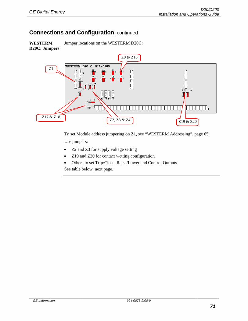
GE Digital Energy D20/D200 Installation and Operations Guide
GE Information 994-0078-2.00-9 71
Connections and Configuration, continued
WESTERM D20C: Jumpers
Jumper locations on the WESTERM D20C:
To set Module address jumpering on Z1, see “WESTERM Addressing”, page 65.
Use jumpers:
• Z2 and Z3 for supply voltage setting • Z19 and Z20 for contact wetting configuration • Others to set Trip/Close, Raise/Lower and Control Outputs See table below, next page.
Z1
Z2, Z3 & Z4 JPs Z17 & Z18
Z9 to Z16
Z19 & Z20 Z17 & Z18

D20/D200 Installation and Operations Guide GE Digital Energy
994-0078-2.00-9 GE Information
72
Connections and Configuration, continued
WESTERM D20C: Settings
The following table gives jumper settings for Z2 to Z20.
Jumper Number
Jumper Position
Jumper Setting
Option 1 Jumper Definition – Status
1A 1B 1C 1D
Z2 & Z3 1 – 2 IN √ √ D20 Peripheral DC Supply Voltage
2 – 3 IN √ √ External DC Supply Voltage on TB1 – 1 & 51
Z19 & Z20
1 – 2, 3 – 4 IN √ √ Contact Wetting Configuration
2 – 3 IN √ √ Group Common Configuration
Option 2 Jumper Definition – Control Wetting Source/Relay Common
2A 2B
Z4 & Z17 1 – 2 IN √ Internal Control Common Supplied on TB1 – 2
2 – 3 IN √ External Control O/P Voltage Source to be Supplied on TB1 – 2
Option 3 Jumper Definition – Control O/P Configuration
3A 3B 3C 3D 3E 3F
Z5 1 – 2 IN √ √ √ √ √ Master T/C source to C control O/P 1 & 2 = (T/C 1 & 2)
2 – 3 IN √ R/L source to C control O/P 1 & 2 = (R/L 4)
Z6 1 – 2 IN √ √ √ √ Master T/C source to C control O/P 3 & 4 = (T/C 3 & 4)
2 – 3 IN √ √ R/L source to C control O/P 3 & 4 = (R/L 3)
Z7 1 – 2 IN √ √ √ Master T/C source to C control O/P 5 & 6 = (T/C 5 & 6)
2 – 3 IN √ √ √ R/L source to C control O/P 5 & 6 = (R/L 2)
Z8 1 – 2 IN √ √ Master T/C source to C control O/P 7 & 8 = (T/C 7 & 8)
2 – 3 IN √ √ √ √ R/L source to C control O/P 7 & 8 = (R/L 1)
Z9 & Z13 1 – 2, 3 – 4 IN √ √ √ √ T/C Configuration (T/C 1 & 2)
1 – 2 IN √ R/L Configuration (R/L 4)
2 – 3 IN √ From C Control Outputs 1 & 2
Z10 & Z14
1 – 2, 3 – 4 IN √ √ √ T/C Configuration (T/C 3 & 4)
1 – 2 IN √ √ R/L Configuration (R/L 3)
2 – 3 IN √ Form C Control Outputs 3 & 4
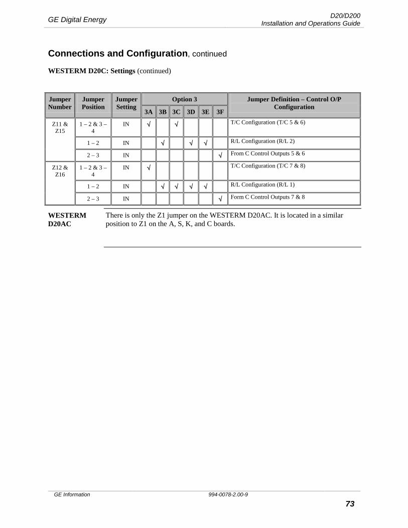
GE Digital Energy D20/D200 Installation and Operations Guide
GE Information 994-0078-2.00-9 73
Connections and Configuration, continued
WESTERM D20C: Settings (continued)
Jumper Number
Jumper Position
Jumper Setting
Option 3 Jumper Definition – Control O/P Configuration
3A 3B 3C 3D 3E 3F
Z11 & Z15
1 – 2 & 3 – 4
IN √ √ T/C Configuration (T/C 5 & 6)
1 – 2 IN √ √ √ R/L Configuration (R/L 2)
2 – 3 IN √ From C Control Outputs 5 & 6
Z12 & Z16
1 – 2 & 3 – 4
IN √ T/C Configuration (T/C 7 & 8)
1 – 2 IN √ √ √ √ R/L Configuration (R/L 1)
2 – 3 IN √ Form C Control Outputs 7 & 8
WESTERM D20AC
There is only the Z1 jumper on the WESTERM D20AC. It is located in a similar position to Z1 on the A, S, K, and C boards.
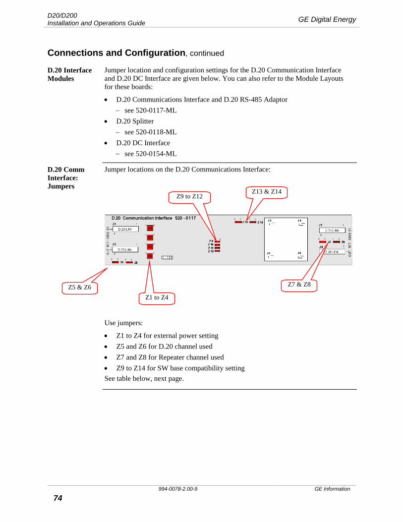
D20/D200 Installation and Operations Guide GE Digital Energy
994-0078-2.00-9 GE Information
74
Connections and Configuration, continued
D.20 Interface Modules
Jumper location and configuration settings for the D.20 Communication Interface and D.20 DC Interface are given below. You can also refer to the Module Layouts for these boards:
• D.20 Communications Interface and D.20 RS-485 Adaptor − see 520-0117-ML
• D.20 Splitter − see 520-0118-ML
• D.20 DC Interface − see 520-0154-ML
D.20 Comm Interface: Jumpers
Jumper locations on the D.20 Communications Interface:
Use jumpers:
• Z1 to Z4 for external power setting • Z5 and Z6 for D.20 channel used • Z7 and Z8 for Repeater channel used • Z9 to Z14 for SW base compatibility setting See table below, next page.
Z5 & Z6 Z1 to Z4
Z7 & Z8
Z9 to Z12 Z13 & Z14
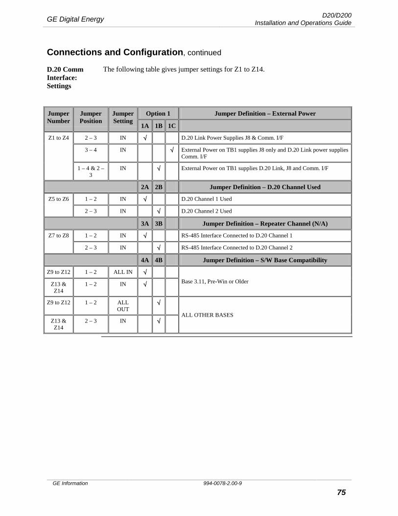
GE Digital Energy D20/D200 Installation and Operations Guide
GE Information 994-0078-2.00-9 75
Connections and Configuration, continued
D.20 Comm Interface: Settings
The following table gives jumper settings for Z1 to Z14.
Jumper Number
Jumper Position
Jumper Setting
Option 1 Jumper Definition – External Power
1A 1B 1C
Z1 to Z4 2 – 3 IN √ D.20 Link Power Supplies J8 & Comm. I/F
3 – 4 IN √ External Power on TB1 supplies J8 only and D.20 Link power supplies Comm. I/F
1 – 4 & 2 – 3
IN √ External Power on TB1 supplies D.20 Link, J8 and Comm. I/F
2A 2B Jumper Definition – D.20 Channel Used
Z5 to Z6 1 – 2 IN √ D.20 Channel 1 Used
2 – 3 IN √ D.20 Channel 2 Used
3A 3B Jumper Definition – Repeater Channel (N/A)
Z7 to Z8 1 – 2 IN √ RS-485 Interface Connected to D.20 Channel 1
2 – 3 IN √ RS-485 Interface Connected to D.20 Channel 2
4A 4B Jumper Definition – S/W Base Compatibility
Z9 to Z12 1 – 2 ALL IN √ Base 3.11, Pre-Win or Older Z13 &
Z14 1 – 2 IN √
Z9 to Z12 1 – 2 ALL OUT
√
ALL OTHER BASES Z13 &
Z14 2 – 3 IN √
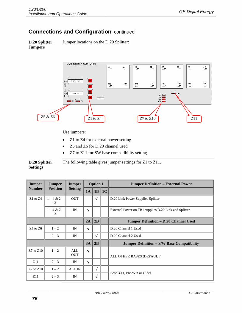
D20/D200 Installation and Operations Guide GE Digital Energy
994-0078-2.00-9 GE Information
76
Connections and Configuration, continued
D.20 Splitter: Jumpers
Jumper locations on the D.20 Splitter:
Use jumpers:
• Z1 to Z4 for external power setting • Z5 and Z6 for D.20 channel used • Z7 to Z11 for SW base compatibility setting
D.20 Splitter: Settings
The following table gives jumper settings for Z1 to Z11.
Jumper Number
Jumper Position
Jumper Setting
Option 1 Jumper Definition – External Power
1A 1B 1C
Z1 to Z4 1 – 4 & 2 – 3
OUT √ D.20 Link Power Supplies Splitter
1 – 4 & 2 – 3
IN √ External Power on TB1 supplies D.20 Link and Splitter
2A 2B Jumper Definition – D.20 Channel Used
Z5 to Z6 1 – 2 IN √ D.20 Channel 1 Used
2 – 3 IN √ D.20 Channel 2 Used
3A 3B Jumper Definition – S/W Base Compatibility
Z7 to Z10 1 – 2 ALL OUT
√ ALL OTHER BASES (DEFAULT)
Z11 2 – 3 IN √
Z7 to Z10 1 – 2 ALL IN √ Base 3.11, Pre-Win or Older
Z11 2 – 3 IN √
Z5 & Z6 Z1 to Z4 Z7 to Z10 Z11
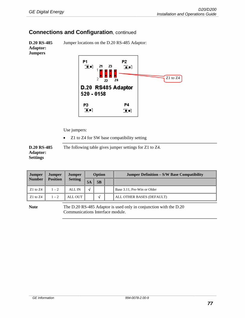
GE Digital Energy D20/D200 Installation and Operations Guide
GE Information 994-0078-2.00-9 77
Connections and Configuration, continued
D.20 RS-485 Adaptor: Jumpers
Jumper locations on the D.20 RS-485 Adaptor:
Use jumpers:
• Z1 to Z4 for SW base compatibility setting
D.20 RS-485 Adaptor: Settings
The following table gives jumper settings for Z1 to Z4.
Jumper Number
Jumper Position
Jumper Setting
Option Jumper Definition – S/W Base Compatibility
5A 5B
Z1 to Z4 1 – 2 ALL IN √ Base 3.11, Pre-Win or Older
Z1 to Z4 1 – 2 ALL OUT √ ALL OTHER BASES (DEFAULT)
Note The D.20 RS-485 Adaptor is used only in conjunction with the D.20 Communications Interface module.
Z1 to Z4
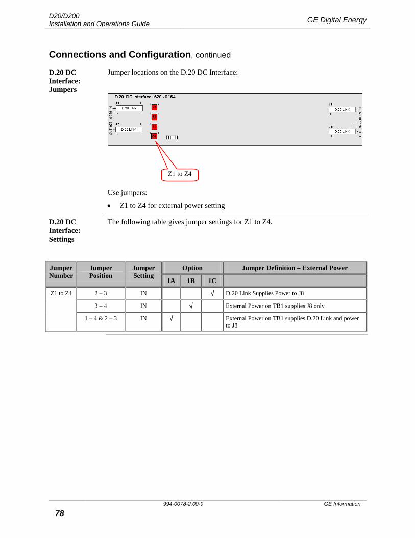
D20/D200 Installation and Operations Guide GE Digital Energy
994-0078-2.00-9 GE Information
78
Connections and Configuration, continued
D.20 DC Interface: Jumpers
Jumper locations on the D.20 DC Interface:
Use jumpers:
• Z1 to Z4 for external power setting
D.20 DC Interface: Settings
The following table gives jumper settings for Z1 to Z4.
Jumper Number
Jumper Position
Jumper Setting
Option Jumper Definition – External Power
1A 1B 1C
Z1 to Z4 2 – 3 IN √ D.20 Link Supplies Power to J8
3 – 4 IN √ External Power on TB1 supplies J8 only
1 – 4 & 2 – 3 IN √ External Power on TB1 supplies D.20 Link and power to J8
Z1 to Z4

GE Digital Energy D20/D200 Installation and Operations Guide
GE Information 994-0078-2.00-9 79
Connections and Configuration, continued
D20EME The D20EME is a self-configuring product. That is, the D20EME main board has no jumpers or switches to define parameters such as:
• VME interrupts • Ethernet bus address • Global memory starting address • Global memory size
EME Main Board Jumper & Component Locations
The following diagram identifies the location of the key components:
J2
JP5
J1
P4 D11 D12
Lithium Batteries BT1 & BT2

D20/D200 Installation and Operations Guide GE Digital Energy
994-0078-2.00-9 GE Information
80
Connections and Configuration, continued
Table: Main Components
This table identifies some of the D20EME main board’s important components.
Component Name Function
JP5 Battery disconnect jumper
Removable jumper when storing board for extended periods.
BT1, BT2 Lithium batteries Maintain NVRAM in the event of a power failure.
J1, J2 Connectors To connect the optional memory expansion daughter board.
P4 Connector Power and communication link to MIC.
D11-A BATT 1 LED Lights when battery voltage drops below 3 Volts. Replace battery immediately.
D11-B BATT 2 LED
D12-A POWER LED +5 Volts power is available.
D12-B ACCESS LED Indicates D20EME is being accessed from VME bus.
D20EME LEDs For LED operation See “D20EME LEDs”, page 116.
Memory Expansion Card
The Memory Expansion card has no user-configurable options.
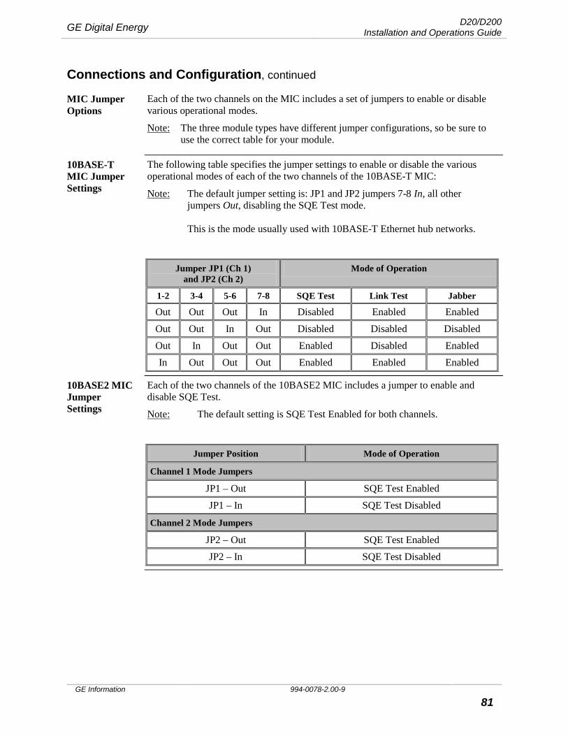
GE Digital Energy D20/D200 Installation and Operations Guide
GE Information 994-0078-2.00-9 81
Connections and Configuration, continued
MIC Jumper Options
Each of the two channels on the MIC includes a set of jumpers to enable or disable various operational modes.
Note: The three module types have different jumper configurations, so be sure to use the correct table for your module.
10BASE-T MIC Jumper Settings
The following table specifies the jumper settings to enable or disable the various operational modes of each of the two channels of the 10BASE-T MIC:
Note: The default jumper setting is: JP1 and JP2 jumpers 7-8 In, all other jumpers Out, disabling the SQE Test mode. This is the mode usually used with 10BASE-T Ethernet hub networks.
Jumper JP1 (Ch 1) and JP2 (Ch 2)
Mode of Operation
1-2 3-4 5-6 7-8 SQE Test Link Test Jabber
Out Out Out In Disabled Enabled Enabled Out Out In Out Disabled Disabled Disabled Out In Out Out Enabled Disabled Enabled In Out Out Out Enabled Enabled Enabled
10BASE2 MIC Jumper Settings
Each of the two channels of the 10BASE2 MIC includes a jumper to enable and disable SQE Test.
Note: The default setting is SQE Test Enabled for both channels.
Jumper Position Mode of Operation
Channel 1 Mode Jumpers
JP1 – Out SQE Test Enabled JP1 – In SQE Test Disabled
Channel 2 Mode Jumpers
JP2 – Out SQE Test Enabled JP2 – In SQE Test Disabled

D20/D200 Installation and Operations Guide GE Digital Energy
994-0078-2.00-9 GE Information
82
Connections and Configuration, continued
10BASE-FL MIC Jumper Settings
Each of the two channels of the 10BASE-FL MIC includes a set of three jumpers to enable and disable various operational modes.
Note: The default jumpering is all jumpers out, enabling SQE test and Jabber, disabling loop back.
Jumper Mode of Operation
Channel 1 Mode Jumpers – JP1
1-2 3-4 5-6 SQE Test Jabber Loop back
Out Out Enabled Enabled In Out Disabled Enabled
Out In Disabled Disabled In Enabled
Out Disabled
Channel 2 Mode Jumpers – JP2
1-2 3-4 5-6 SQE Test Jabber Loop back
Out Out Enabled Enabled In Out Disabled Enabled
Out In Disabled Disabled In Enabled
Out Disabled
10BASE-FL Fiber Cable Connectors
The 10BASE-FL module has four ST-Type bayonet fiber-optic cable connectors on the rear edge of the card.
The positions of the input and output connectors for each channel are shown in the diagram to the right.
Note: Labels can be seen on the PCB stencil, beside each of the connectors.
LAN AReceive
LAN BReceive
LAN ATransmit
LAN BTransmit
Rear View of10BASE-FL MIC

GE Digital Energy D20/D200 Installation and Operations Guide
GE Information 994-0078-2.00-9 83
Connections and Configuration, continued
Redundant D20/D200 Systems
To implement a redundant D20/D200 system, you need: • A second CCU, built and configured the same as the first CCU • RS-232 Switch Panel(s) • Two RS-232 Switch Panel Monitor and Control cables, referred to as Watchdog
cables, connecting each CCU to the RS-232 Switch Panel. Refer to “Procedure: Installing Watchdog Cables” on page 85 for details.
• One inter-CCU communications cable, providing either a Ping connection, or a (D.20) HDLC connection, between CCUs A and B. The method used depends on the availability of serial and D.20 ports. As appropriate, refer to: − “Procedure: Installing a Ping Cable” on page 85 − “Procedure: Installing an HDLC Cable” on page 86.
• Serial communication cables. The number of serial cables depends on your system configuration. Serial connections from CCUs to your field equipment are cabled and switched through the RS-232 Switch Panel. The RS-232 Switch Panel switches up to eight communications links to the Standby CCU, in the event of a failure of the Active CCU. See “Procedure: Connecting Serial Communi-cation Cables” on page 86 for details.
Note: Refer to “Required Components” on page 84 for component part numbers and functions.
Note: Refer to “D20/D200 Redundancy” on page 39 for a description of D20/D200 redundancy.
Note: The RS-232 Switch Panel is not equipped with EMI protection circuitry. If the connection length exceeds 3m, a Serial Surge Protection Panel (GE item number 540-0249) or equivalent protection device should be installed.
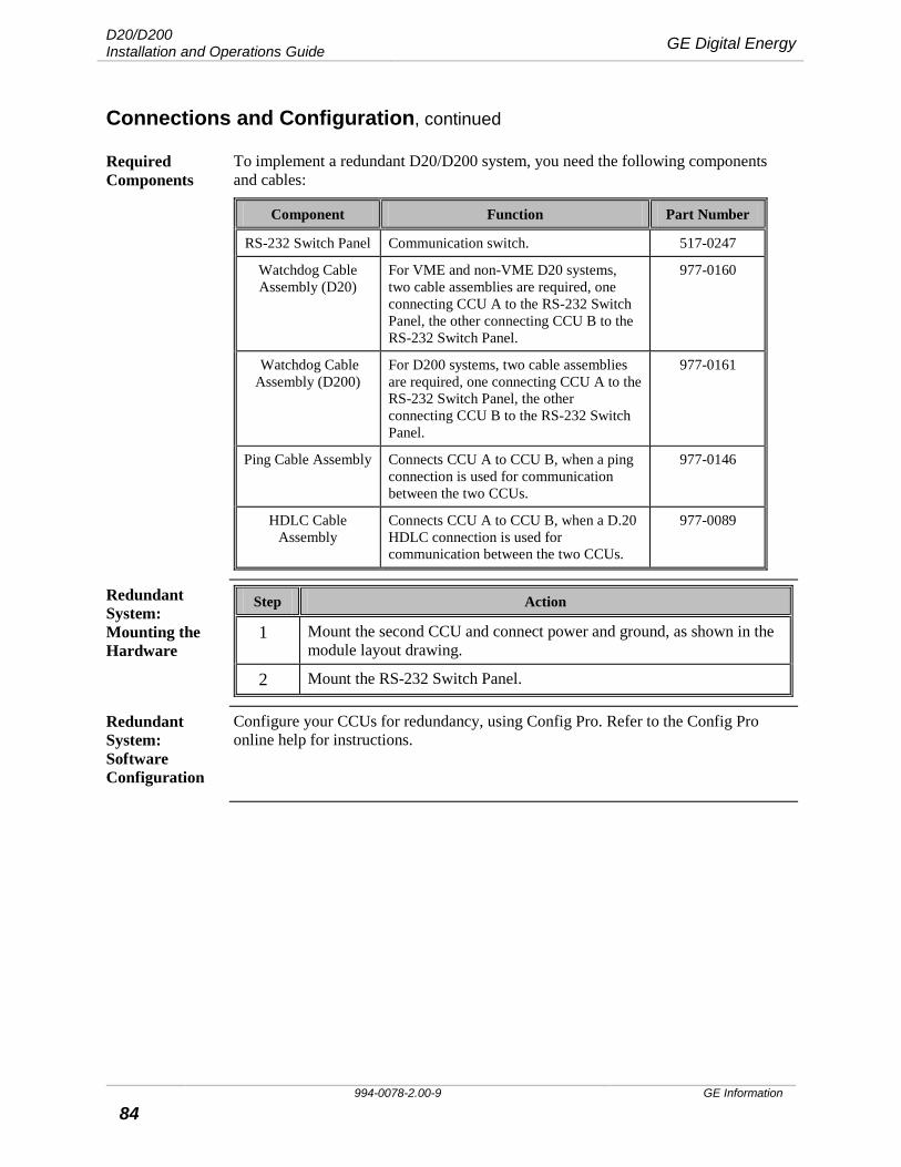
D20/D200 Installation and Operations Guide GE Digital Energy
994-0078-2.00-9 GE Information
84
Connections and Configuration, continued
Required Components
To implement a redundant D20/D200 system, you need the following components and cables:
Component Function Part Number
RS-232 Switch Panel Communication switch. 517-0247
Watchdog Cable Assembly (D20)
For VME and non-VME D20 systems, two cable assemblies are required, one connecting CCU A to the RS-232 Switch Panel, the other connecting CCU B to the RS-232 Switch Panel.
977-0160
Watchdog Cable Assembly (D200)
For D200 systems, two cable assemblies are required, one connecting CCU A to the RS-232 Switch Panel, the other connecting CCU B to the RS-232 Switch Panel.
977-0161
Ping Cable Assembly Connects CCU A to CCU B, when a ping connection is used for communication between the two CCUs.
977-0146
HDLC Cable Assembly
Connects CCU A to CCU B, when a D.20 HDLC connection is used for communication between the two CCUs.
977-0089
Redundant System: Mounting the Hardware
Step Action
1 Mount the second CCU and connect power and ground, as shown in the module layout drawing.
2 Mount the RS-232 Switch Panel.
Redundant System: Software Configuration
Configure your CCUs for redundancy, using Config Pro. Refer to the Config Pro online help for instructions.
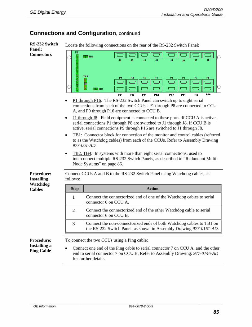
GE Digital Energy D20/D200 Installation and Operations Guide
GE Information 994-0078-2.00-9 85
Connections and Configuration, continued
RS-232 Switch Panel: Connectors
Locate the following connections on the rear of the RS-232 Switch Panel:
• P1 through P16: The RS-232 Switch Panel can switch up to eight serial connections from each of the two CCUs - P1 through P8 are connected to CCU A, and P9 through P16 are connected to CCU B.
• J1 through J8: Field equipment is connected to these ports. If CCU A is active, serial connections P1 through P8 are switched to J1 through J8. If CCU B is active, serial connections P9 through P16 are switched to J1 through J8.
• TB1: Connector block for connection of the monitor and control cables (referred to as the Watchdog cables) from each of the CCUs. Refer to Assembly Drawing 977-061-AD
• TB2, TB4: In systems with more than eight serial connections, used to interconnect multiple RS-232 Switch Panels, as described in “Redundant Multi-Node Systems” on page 86.
Procedure: Installing Watchdog Cables
Connect CCUs A and B to the RS-232 Switch Panel using Watchdog cables, as follows:
Step Action
1 Connect the connectorized end of one of the Watchdog cables to serial connector 6 on CCU A.
2 Connect the connectorized end of the other Watchdog cable to serial connector 6 on CCU B.
3 Connect the non-connectorized ends of both Watchdog cables to TB1 on the RS-232 Switch Panel, as shown in Assembly Drawing 977-0161-AD.
Procedure: Installing a Ping Cable
To connect the two CCUs using a Ping cable:
• Connect one end of the Ping cable to serial connector 7 on CCU A, and the other end to serial connector 7 on CCU B. Refer to Assembly Drawing: 977-0146-AD for further details.
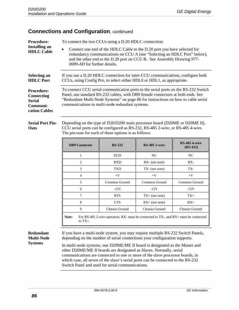
D20/D200 Installation and Operations Guide GE Digital Energy
994-0078-2.00-9 GE Information
86
Connections and Configuration, continued
Procedure: Installing an HDLC Cable
To connect the two CCUs using a D.20 HDLC connection:
• Connect one end of the HDLC Cable to the D.20 port you have selected for redundancy communications on CCU A (see “Selecting an HDLC Port” below), and the other end to the D.20 port on CCU B. See Assembly Drawing 977-0089-AD for further details.
Selecting an HDLC Port
If you use a D.20 HDLC connection for inter-CCU communications, configure both CCUs, using Config Pro, to select either HDL0 or HDL1, as appropriate.
Procedure: Connecting Serial Communi-cation Cables
To connect CCU serial communication ports to the serial ports on the RS-232 Switch Panel, use standard RS-232 cables, with DB9 female connectors at both ends. See “Redundant Multi-Node Systems” on page 86 for instructions on how to cable serial communications in multi-node redundant systems.
Serial Port Pin-Outs
Depending on the type of D20/D200 main processor board (D20ME or D20ME II), CCU serial ports can be configured as RS-232, RS-485 2-wire, or RS-485 4-wire. The pin-outs for each of these options is as follows:
DB9 Connector RS-232 RS-485 2-wire RS-485 4-wire (RS-422)
1 DCD NC NC
2 RXD RX- (see note) RX-
3 TXD TX- (see note) TX-
4 +V +V +V
5 Common Ground Common Ground Common Ground
6 -12V -12V -12V
7 RTS TX+ (see note) TX+
8 CTS RX+ (see note) RX+
9 Chassis Ground Chassis Ground Chassis Ground
Note: For RS-485 2-wire operation, RX- must be connected to TX-, and RX+ must be connected to TX+.
Redundant Multi-Node Systems
If you have a multi-node system, you may require multiple RS-232 Switch Panels, depending on the number of serial connections your configuration supports.
In multi-node systems, one D20ME/ME II board is designated as the Master and other D20ME/ME II boards are designated as Slaves. Normally, serial communications are connected to one or more of the slave processor boards, in which case, all seven of the slave’s serial ports can be connected to the RS-232 Switch Panel and used for serial communications.
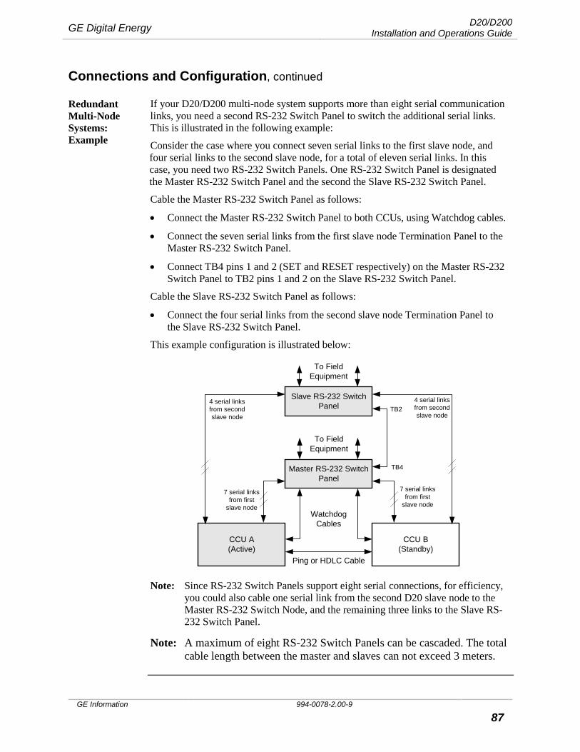
GE Digital Energy D20/D200 Installation and Operations Guide
GE Information 994-0078-2.00-9 87
Connections and Configuration, continued
Redundant Multi-Node Systems: Example
If your D20/D200 multi-node system supports more than eight serial communication links, you need a second RS-232 Switch Panel to switch the additional serial links. This is illustrated in the following example:
Consider the case where you connect seven serial links to the first slave node, and four serial links to the second slave node, for a total of eleven serial links. In this case, you need two RS-232 Switch Panels. One RS-232 Switch Panel is designated the Master RS-232 Switch Panel and the second the Slave RS-232 Switch Panel.
Cable the Master RS-232 Switch Panel as follows:
• Connect the Master RS-232 Switch Panel to both CCUs, using Watchdog cables.
• Connect the seven serial links from the first slave node Termination Panel to the Master RS-232 Switch Panel.
• Connect TB4 pins 1 and 2 (SET and RESET respectively) on the Master RS-232 Switch Panel to TB2 pins 1 and 2 on the Slave RS-232 Switch Panel.
Cable the Slave RS-232 Switch Panel as follows:
• Connect the four serial links from the second slave node Termination Panel to the Slave RS-232 Switch Panel.
This example configuration is illustrated below:
Master RS-232 SwitchPanel
CCU A(Active)
CCU B(Standby)
WatchdogCables
Ping or HDLC Cable
To FieldEquipment
Slave RS-232 SwitchPanel
To FieldEquipment
TB4
TB2
7 serial linksfrom first
slave node
7 serial linksfrom first
slave node
4 serial linksfrom secondslave node
4 serial linksfrom secondslave node
Note: Since RS-232 Switch Panels support eight serial connections, for efficiency, you could also cable one serial link from the second D20 slave node to the Master RS-232 Switch Node, and the remaining three links to the Slave RS-232 Switch Panel.
Note: A maximum of eight RS-232 Switch Panels can be cascaded. The total cable length between the master and slaves can not exceed 3 meters.

D20/D200 Installation and Operations Guide GE Digital Energy
994-0078-2.00-9 GE Information
88
Connections and Configuration, continued
Testing Redundancy
Once you have correctly connected and configured your D20/D200 redundant system, power up and test the system for fail over.
Universal Protocol Converter
The UPC contains a jumper field that is configured specifically for each protocol. Jumpers are pre-set at the factory and should not have to be changed.
See the Configuration Guide for the protocol for the jumper settings that are required.
WESMAINT Cable Pinouts
WESMAINT cable DB-9 connectors pinouts:
GE Digital Energy D20/D200 Installation and Operations Guide
GE Information 994-0078-2.00-9 89
Power-up and Test Power-up and test the D20/D200
Once you have made all field wiring and communication connections and have completed the necessary hardware configuration, the next step is to power-up the D20/D200 and verify that it is functioning properly.
Use this section of the guide to prepare for powering-up and learn how to correctly perform the power-up and other tests:
• What is needed to test: WESMAINT II+ facility, 68K Monitor and Config Pro • How to power-up the D20/D200 and conduct the BOOT Test: Power On Self-
Test • How to carry out a redundant system test
Note Before any of the tests and procedures in this section can be performed, a valid configuration file must be loaded into the D20/D200’s NVRAM.
If you have replaced the main board of the D20/D200, then you will need to restore the configuration file so that diagnostic tests can be performed.
If this power-up and test procedure reveals that your D20/D200 is not functioning properly due to software malfunction, then you need to download code and configuration files.
See “D20/D200 Software Configuration”, page 99 and refer to the Config Pro On Line Help.
Required for Testing
The system components that are required for configuring and testing the D20/D200 are:
• WESMAINT II+ facility • 68K Monitor • Config Pro system
!
Important Checks
To prevent burning out the main processor board, make two important checks before switching on the D20 or D200:
• Check that the external power supply input level is correct for the Power Supply fitted to the chassis. See “Standard Power Supplies”, page 27
• If you have 125VDC or 110VAC input, then jumpers Z22 and Z23 on the WESTERM D20M+: 517 – 0225 or 517 – 0224 must be jumpered 2 – 3.

D20/D200 Installation and Operations Guide GE Digital Energy
994-0078-2.00-9 GE Information
90
Power-up and Test, continued
Accessing WESMAINT II+ Using a Terminal
You can use a VT100-compatible terminal or a terminal emulation program to directly access the WESMAINT II+ facility. Config Pro’s Terminal Emulator is an example of a suitable terminal emulation program.
Note: For further information about using WESMAINT II+ software to perform any of the test procedures in this section, refer to the WESMAINT II+ User’s Guide.
Note Microsoft Windows™ HyperTerminal can be used for terminal emulation but it is NOT recommended because code and configuration file download times are considerably increased.
68K Monitor The 68K Monitor is a debugging and diagnostics tool that is accessible as a menu selection in WESMAINT II+, or from a basic login prompt if WESMAINT is not available.
Note: For further information about using the 68K Monitor, refer to the 68K Monitor User’s Guide.
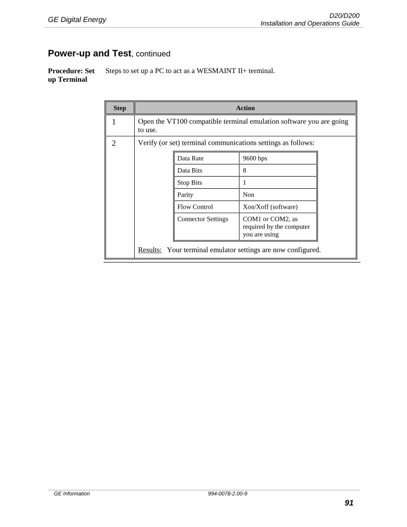
GE Digital Energy D20/D200 Installation and Operations Guide
GE Information 994-0078-2.00-9 91
Power-up and Test, continued
Procedure: Set up Terminal
Steps to set up a PC to act as a WESMAINT II+ terminal.
Step Action
1 Open the VT100 compatible terminal emulation software you are going to use.
2 Verify (or set) terminal communications settings as follows:
Data Rate 9600 bps
Data Bits 8
Stop Bits 1
Parity Non
Flow Control Xon/Xoff (software)
Connector Settings COM1 or COM2, as required by the computer you are using
Results: Your terminal emulator settings are now configured.
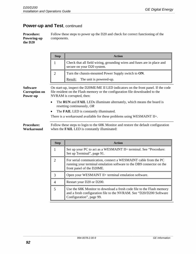
D20/D200 Installation and Operations Guide GE Digital Energy
994-0078-2.00-9 GE Information
92
Power-up and Test, continued
Procedure: Powering-up the D20
Follow these steps to power up the D20 and check for correct functioning of the components.
Step Action
1 Check that all field wiring, grounding wires and fuses are in place and secure on your D20 system.
2 Turn the chassis-mounted Power Supply switch to ON.
Result: The unit is powered-up.
Software Corruption on Power-up
On start-up, inspect the D20ME/ME II LED indicators on the front panel. If the code file resident on the Flash memory or the configuration file downloaded to the NVRAM is corrupted, then:
• The RUN and FAIL LEDs illuminate alternately, which means the board is resetting continuously, OR
• The FAIL LED is constantly illuminated. There is a workaround available for these problems using WESMAINT II+.
Procedure: Workaround
Follow these steps to login to the 68K Monitor and restore the default configuration when the FAIL LED is constantly illuminated:
Step Action
1 Set up your PC to act as a WESMAINT II+ terminal. See “Procedure: Set up Terminal”, page 91.
2 For serial communication, connect a WESMAINT cable from the PC running your terminal emulation software to the DB9 connector on the front panel of the D20ME.
3 Open your WESMAINT II+ terminal emulation software.
4 Restart your D20 or D200.
5 Use the 68K Monitor to download a fresh code file to the Flash memory and a fresh configuration file to the NVRAM. See “D20/D200 Software Configuration”, page 99.
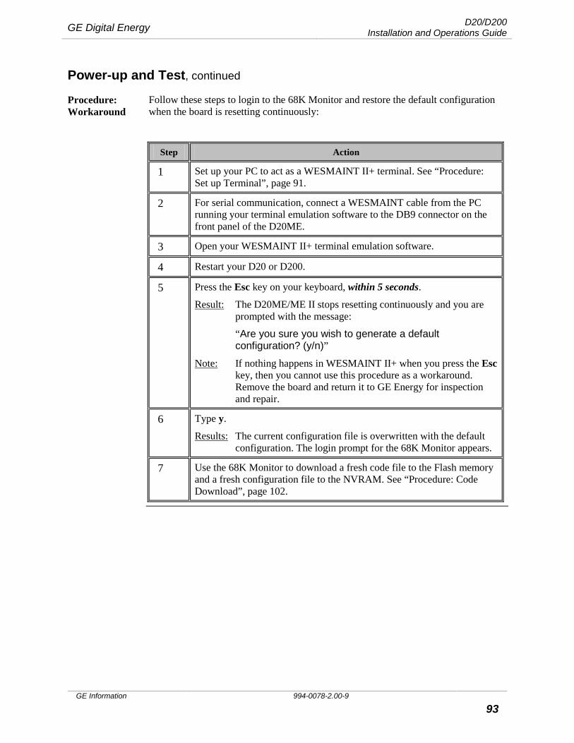
GE Digital Energy D20/D200 Installation and Operations Guide
GE Information 994-0078-2.00-9 93
Power-up and Test, continued
Procedure: Workaround
Follow these steps to login to the 68K Monitor and restore the default configuration when the board is resetting continuously:
Step Action
1 Set up your PC to act as a WESMAINT II+ terminal. See “Procedure: Set up Terminal”, page 91.
2 For serial communication, connect a WESMAINT cable from the PC running your terminal emulation software to the DB9 connector on the front panel of the D20ME.
3 Open your WESMAINT II+ terminal emulation software.
4 Restart your D20 or D200.
5 Press the Esc key on your keyboard, within 5 seconds.
Result: The D20ME/ME II stops resetting continuously and you are prompted with the message:
“Are you sure you wish to generate a default configuration? (y/n)”
Note: If nothing happens in WESMAINT II+ when you press the Esc key, then you cannot use this procedure as a workaround. Remove the board and return it to GE Energy for inspection and repair.
6 Type y.
Results: The current configuration file is overwritten with the default configuration. The login prompt for the 68K Monitor appears.
7 Use the 68K Monitor to download a fresh code file to the Flash memory and a fresh configuration file to the NVRAM. See “Procedure: Code Download”, page 102.

D20/D200 Installation and Operations Guide GE Digital Energy
994-0078-2.00-9 GE Information
94
Power-up and Test, continued
On-Line Start-up Test
The D20 and D200 automatically boots up when the power is switched on. Internal processes perform a series of routines. Self-diagnostic tests are performed followed by the spawning of all the software applications that reside in the unit’s memory.
The self-diagnostic tests generate PASS or FAIL messages that can be viewed in your terminal emulator WESMAINT II+ screen. You can also see the results of the application spawning process.
Pass/Fail tests are carried out on the:
• BootROM • User RAM • NVRAM • EPROM memory • Root process The self-diagnostics also return measures on memory sizes for:
• RAM • EPROM • NVRAM The board ID address is returned, which is useful for multi-node systems.
The LNVRAM CRC test verifies that the configuration header is valid. If this fails, then the D20ME/ME II starts using only the BootROM applications and operating system. See “Configuration File Download”, page 107.
Code and Configuration files
If the code and configuration files compiled for your specific system are already downloaded, then you can login straightaway to WESMAINT II+ for powering-up and testing.
If your system-specific code and configuration files are not downloaded, then you need to power-up with the default configuration. You can then login to the 68K Monitor, download your system-specific files and restart the D20 or D200 for testing.
See “D20/D200 Software Configuration”, page 99 and Config Pro On Line Help.
Further Testing For further specific testing, log in to WESMAINT II+. See the WESMAINT II+ Users Guide and WESMAINT user guides for specific applications.
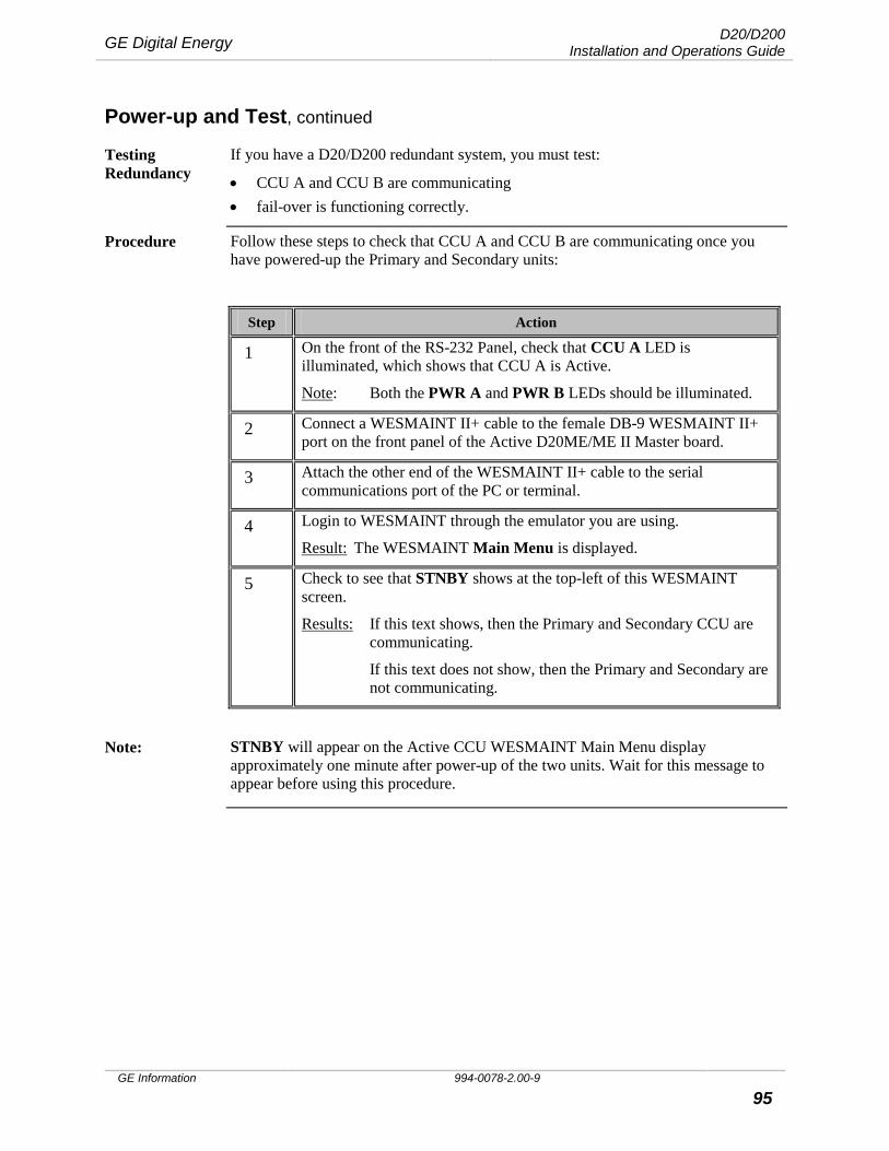
GE Digital Energy D20/D200 Installation and Operations Guide
GE Information 994-0078-2.00-9 95
Power-up and Test, continued
Testing Redundancy
If you have a D20/D200 redundant system, you must test:
• CCU A and CCU B are communicating • fail-over is functioning correctly.
Procedure Follow these steps to check that CCU A and CCU B are communicating once you have powered-up the Primary and Secondary units:
Step Action
1 On the front of the RS-232 Panel, check that CCU A LED is illuminated, which shows that CCU A is Active.
Note: Both the PWR A and PWR B LEDs should be illuminated.
2 Connect a WESMAINT II+ cable to the female DB-9 WESMAINT II+ port on the front panel of the Active D20ME/ME II Master board.
3 Attach the other end of the WESMAINT II+ cable to the serial communications port of the PC or terminal.
4 Login to WESMAINT through the emulator you are using.
Result: The WESMAINT Main Menu is displayed.
5 Check to see that STNBY shows at the top-left of this WESMAINT screen.
Results: If this text shows, then the Primary and Secondary CCU are communicating.
If this text does not show, then the Primary and Secondary are not communicating.
Note: STNBY will appear on the Active CCU WESMAINT Main Menu display
approximately one minute after power-up of the two units. Wait for this message to appear before using this procedure.
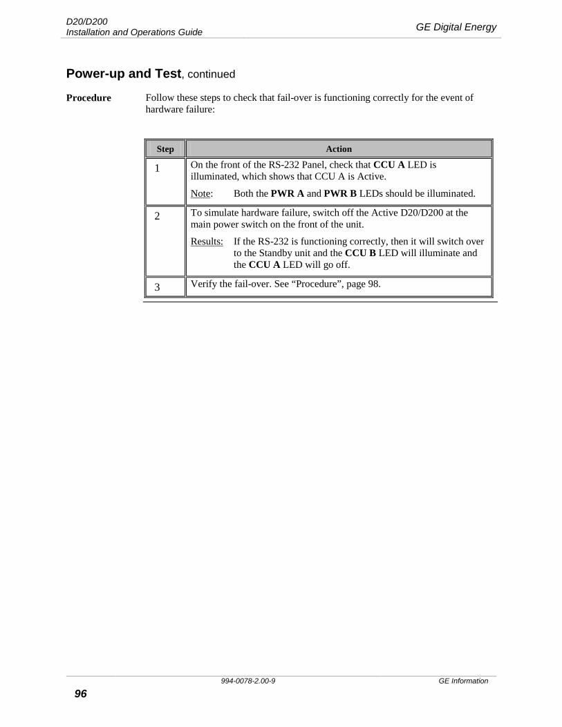
D20/D200 Installation and Operations Guide GE Digital Energy
994-0078-2.00-9 GE Information
96
Power-up and Test, continued
Procedure Follow these steps to check that fail-over is functioning correctly for the event of hardware failure:
Step Action
1 On the front of the RS-232 Panel, check that CCU A LED is illuminated, which shows that CCU A is Active.
Note: Both the PWR A and PWR B LEDs should be illuminated.
2 To simulate hardware failure, switch off the Active D20/D200 at the main power switch on the front of the unit.
Results: If the RS-232 is functioning correctly, then it will switch over to the Standby unit and the CCU B LED will illuminate and the CCU A LED will go off.
3 Verify the fail-over. See “Procedure”, page 98.
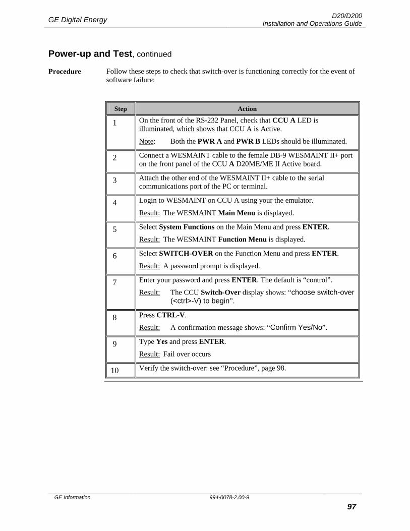
GE Digital Energy D20/D200 Installation and Operations Guide
GE Information 994-0078-2.00-9 97
Power-up and Test, continued
Procedure Follow these steps to check that switch-over is functioning correctly for the event of software failure:
Step Action
1 On the front of the RS-232 Panel, check that CCU A LED is illuminated, which shows that CCU A is Active.
Note: Both the PWR A and PWR B LEDs should be illuminated.
2 Connect a WESMAINT cable to the female DB-9 WESMAINT II+ port on the front panel of the CCU A D20ME/ME II Active board.
3 Attach the other end of the WESMAINT II+ cable to the serial communications port of the PC or terminal.
4 Login to WESMAINT on CCU A using your the emulator.
Result: The WESMAINT Main Menu is displayed.
5 Select System Functions on the Main Menu and press ENTER.
Result: The WESMAINT Function Menu is displayed.
6 Select SWITCH-OVER on the Function Menu and press ENTER.
Result: A password prompt is displayed.
7 Enter your password and press ENTER. The default is “control”.
Result: The CCU Switch-Over display shows: “choose switch-over (<ctrl>-V) to begin”.
8 Press CTRL-V.
Result: A confirmation message shows: “Confirm Yes/No”.
9 Type Yes and press ENTER.
Result: Fail over occurs
10 Verify the switch-over: see “Procedure”, page 98.
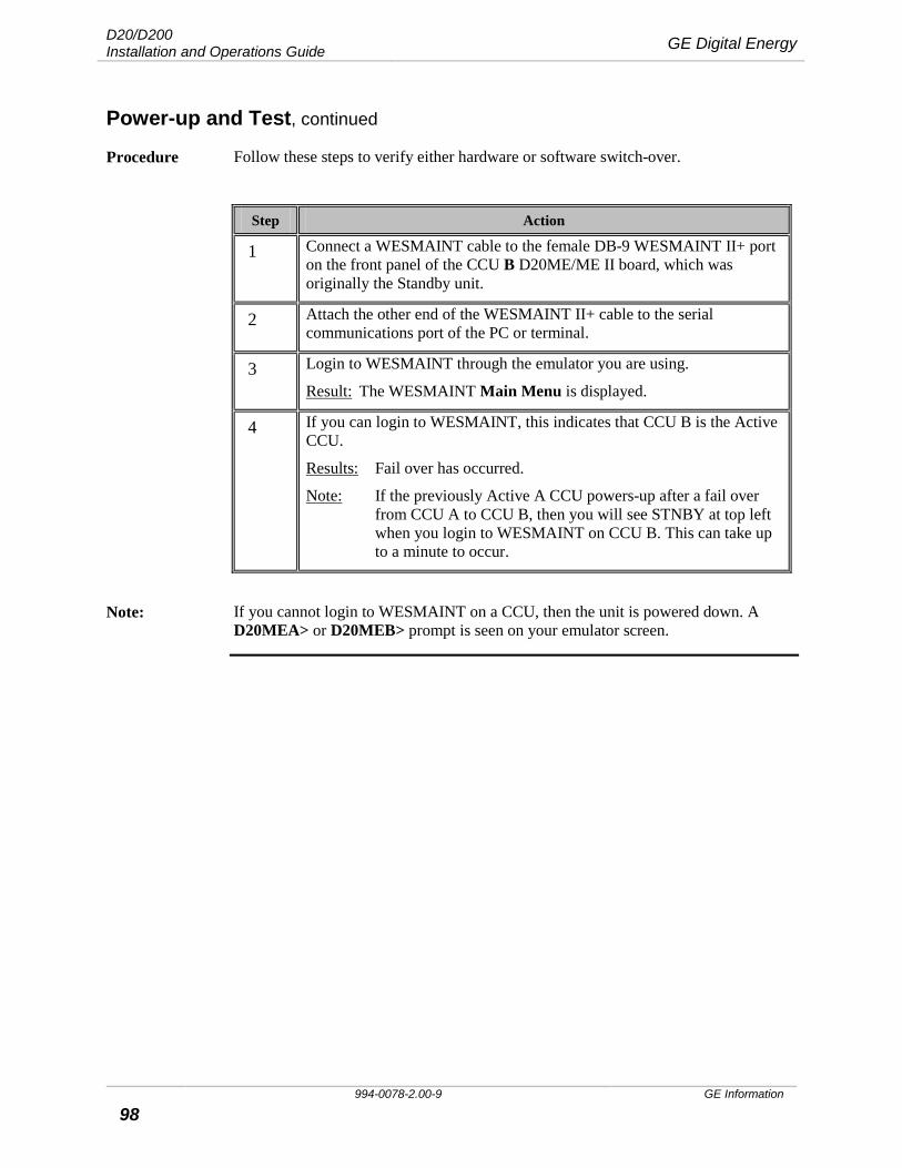
D20/D200 Installation and Operations Guide GE Digital Energy
994-0078-2.00-9 GE Information
98
Power-up and Test, continued
Procedure Follow these steps to verify either hardware or software switch-over.
Step Action
1 Connect a WESMAINT cable to the female DB-9 WESMAINT II+ port on the front panel of the CCU B D20ME/ME II board, which was originally the Standby unit.
2 Attach the other end of the WESMAINT II+ cable to the serial communications port of the PC or terminal.
3 Login to WESMAINT through the emulator you are using.
Result: The WESMAINT Main Menu is displayed.
4 If you can login to WESMAINT, this indicates that CCU B is the Active CCU.
Results: Fail over has occurred.
Note: If the previously Active A CCU powers-up after a fail over from CCU A to CCU B, then you will see STNBY at top left when you login to WESMAINT on CCU B. This can take up to a minute to occur.
Note: If you cannot login to WESMAINT on a CCU, then the unit is powered down. A
D20MEA> or D20MEB> prompt is seen on your emulator screen.
GE Digital Energy D20/D200 Installation and Operations Guide
GE Information 994-0078-2.00-9 99
D20/D200 Software Configuration This Section Use this section as a guide for:
• An introduction to the software components used in the D20ME/ME II module • How to identify the type of Base software installed on your D20ME/ME II
module • An overview of the software tools you will use • How to download code and configuration files to the Flash memory on your
D20ME/ME II module or modules on your system using a serial connection
D20 and D200 Software: Introduction
The D20ME has Base software installed at manufacture, which resides in the BootROM. When the D20ME is first powered up, the Base system builds a default configuration header file in the NVRAM memory. The default configuration allows the D20ME to start and run the 68K Monitor. You use the 68K Monitor to perform the necessary software download to the D20ME.
The D20/D200 is factory tested. The level of software testing that is performed on the D20 or D200 before it leaves the factory depends upon the type of delivery and system:
• If you have not ordered software, then the D20ME has been powered-up in the factory and checked to see that the 68K Monitor login comes up
• If you have ordered software, then your project-specific code and configuration files have been downloaded
• For multi-node systems, a default code and configuration file has been loaded to carry out further tests.
To meet the full operational requirements of a specific RTU system, the D20ME main processor board requires two valid files to be loaded:
• A code file, which resides in the EPROM or Flash memory • A configuration file, which consist of applications and which resides in the
NVRAM Use this section to load the project-specific code and configuration files that have been built for the specific operational needs of your RTU system.
When to Download
Instances where you may need to download code and configuration files to your D20/D200:
• When you want to change firmware or configuration settings. • If the D20 or D200 has performed self-diagnostics and determined that the
FLASH memory is either erased or corrupted. • When test messages indicate that the FLASH memory has been erased or
corrupted or that a valid configuration file header cannot be found in the NVRAM.
• After maintenance or replacement work that has deleted the FLASH code files.

D20/D200 Installation and Operations Guide GE Digital Energy
994-0078-2.00-9 GE Information
100
D20/D200 Software Configuration, continued
Base Types There are two types of Base system software: D20 Base and CCU Base.
Identification of Base Type
The D20ME module Base Type is determined by the version of BootROM installed, which identifies how the module will be used. Since the download method depends on which BootROM is installed, the Base type of the module must be known before downloading flash code. The BootROM label indicates which type you have:
Module Base Type BootROM Label
D20ME D20 Base SBU0000/xx
D20ME CCU Base SBU0001/xx
Note The /xx suffix in the BootROM Label is the revision number of the software
Alternate Identification Method
If the D20ME module is already installed into a device and difficult to remove, you can identify the Base Type through the WESMAINT monitor See “Procedure: Identify Base”, page 101.
Prerequisites for Code Download
The items following must be available before a flash code file can be loaded into a D20ME:
• Windows PC with terminal emulation communication software loaded. • The code file, in the Motorola® S-record format, preferably located on a local
hard drive. − If the file is located on a network or floppy drive, the download may be
significantly slower. − This file typically will be named: down.shx or salxxxx.shx
• A WESMAINT cable for connecting the PC to the D20ME WESMAINT port on the front-panel.
• The D20ME module must: − have its hardware option jumpers set − be installed into a D20 or D200 chassis, ready to power-up
Note: If you are upgrading from a D20M++ board to a D20ME board, you must use the .shx file for the ME board, not the .bin file.

GE Digital Energy D20/D200 Installation and Operations Guide
GE Information 994-0078-2.00-9 101
D20/D200 Software Configuration, continued
Setup WESMAINT II+ terminal
To set up a PC to act as a WESMAINT II+ terminal, see “Power-up and Test”, page 89.
Procedure: Identify Base
If the D20ME BootROM Base Type is already known, skip this procedure.
Step Action
Configure and Connect PC to D20ME
1 Connect a WESMAINT cable from the PC’s com port to the D20ME front panel WESMAINT port.
Identify D20ME Type
2 Restart the D20ME (power off-on cycle) while watching the PC monitor.
If the first line of output text is: Board type is:
P149-0 D20ME BOOTROM D20 Base
P130-0, GE Energy Services CCUME BootROM CCU Base
D20ME: Flash Memory
The following table shows possibles allocation of the 2 MB FLASH memory. Check that the settings for memory mapping in Config Pro match the allocation.
Software Allocation Typical Allocation
D20 Base 1MB or 2MB 1MB is the typical allocation for this Base
CCU Base 1MB or 2MB 2MB is the typical allocation for this Base
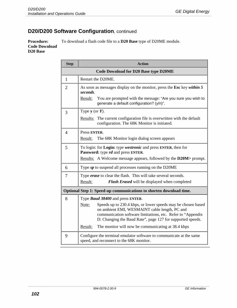
D20/D200 Installation and Operations Guide GE Digital Energy
994-0078-2.00-9 GE Information
102
D20/D200 Software Configuration, continued
Procedure: Code Download D20 Base
To download a flash code file to a D20 Base type of D20ME module.
Step Action
Code Download for D20 Base type D20ME
1 Restart the D20ME.
2 As soon as messages display on the monitor, press the Esc key within 5 seconds. Result: You are prompted with the message: “Are you sure you wish to
generate a default configuration? (y/n)”.
3 Type y (or Y).
Results: The current configuration file is overwritten with the default configuration. The 68K Monitor is initiated.
4 Press ENTER. Result: The 68K Monitor login dialog screen appears
5 To login: for Login: type westronic and press ENTER, then for Password: type rd and press ENTER. Results: A Welcome message appears, followed by the D20M> prompt.
6 Type sp to suspend all processes running on the D20ME
7 Type erase to clear the flash. This will take several seconds. Result: Flash Erased will be displayed when completed
Optional Step 1: Speed-up communications to shorten download time.
8 Type Baud 38400 and press ENTER. Note: Speeds up to 230.4 kbps, or lower speeds may be chosen based
on ambient EMI, WESMAINT cable length, PC and communication software limitations, etc. Refer to “Appendix D: Changing the Baud Rate”, page 127 for supported speeds.
Result: The monitor will now be communicating at 38.4 kbps
9 Configure the terminal emulator software to communicate at the same speed, and reconnect to the 68K monitor.
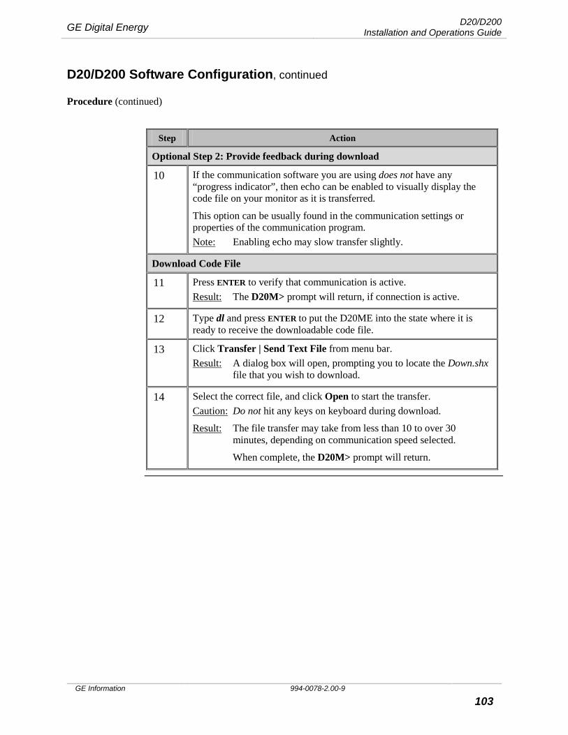
GE Digital Energy D20/D200 Installation and Operations Guide
GE Information 994-0078-2.00-9 103
D20/D200 Software Configuration, continued
Procedure (continued)
Step Action
Optional Step 2: Provide feedback during download
10 If the communication software you are using does not have any “progress indicator”, then echo can be enabled to visually display the code file on your monitor as it is transferred.
This option can be usually found in the communication settings or properties of the communication program. Note: Enabling echo may slow transfer slightly.
Download Code File
11 Press ENTER to verify that communication is active. Result: The D20M> prompt will return, if connection is active.
12 Type dl and press ENTER to put the D20ME into the state where it is ready to receive the downloadable code file.
13 Click Transfer | Send Text File from menu bar. Result: A dialog box will open, prompting you to locate the Down.shx
file that you wish to download.
14 Select the correct file, and click Open to start the transfer. Caution: Do not hit any keys on keyboard during download.
Result: The file transfer may take from less than 10 to over 30 minutes, depending on communication speed selected.
When complete, the D20M> prompt will return.
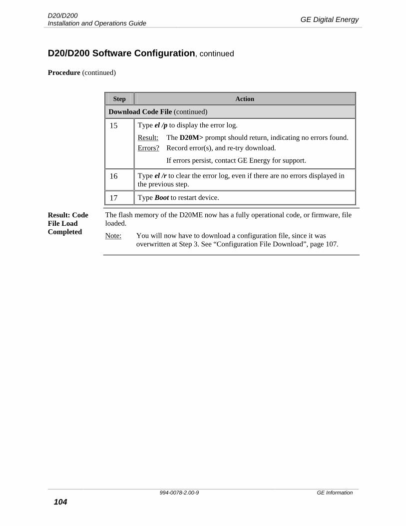
D20/D200 Installation and Operations Guide GE Digital Energy
994-0078-2.00-9 GE Information
104
D20/D200 Software Configuration, continued
Procedure (continued)
Step Action
Download Code File (continued)
15 Type el /p to display the error log.
Result: The D20M> prompt should return, indicating no errors found. Errors? Record error(s), and re-try download.
If errors persist, contact GE Energy for support.
16 Type el /r to clear the error log, even if there are no errors displayed in the previous step.
17 Type Boot to restart device.
Result: Code File Load Completed
The flash memory of the D20ME now has a fully operational code, or firmware, file loaded.
Note: You will now have to download a configuration file, since it was overwritten at Step 3. See “Configuration File Download”, page 107.

GE Digital Energy D20/D200 Installation and Operations Guide
GE Information 994-0078-2.00-9 105
D20/D200 Software Configuration, continued
Procedure: Code Download CCU Base
To download of a flash code file to a CCU type of D20ME module.
Step Action
Code Download for CCU Base type D20ME
1 Restart the D20ME.
2 When messages appear on the monitor, press SPACEBAR within 5 seconds. Result: You are prompted with the message: “Are you sure you wish to
abort the flash boot? (y/n)”.
3 Type y (or Y) to abort the normal startup.
4 Press ENTER. Result: The login dialog appears.
5 To login: for Login: type westronic and press ENTER, then for Password: type rd and press ENTER. Result: After a Welcome message, the D20MES> prompt will appear.
6 Type sp to suspend all processes running on the D20ME
7 Type erase to clear the flash. This will take several seconds. Result: The monitor will display, before returning the D20MES>
prompt:
Erasing FLASH memory < \ Checking FLASH contents… \
Continued on next page
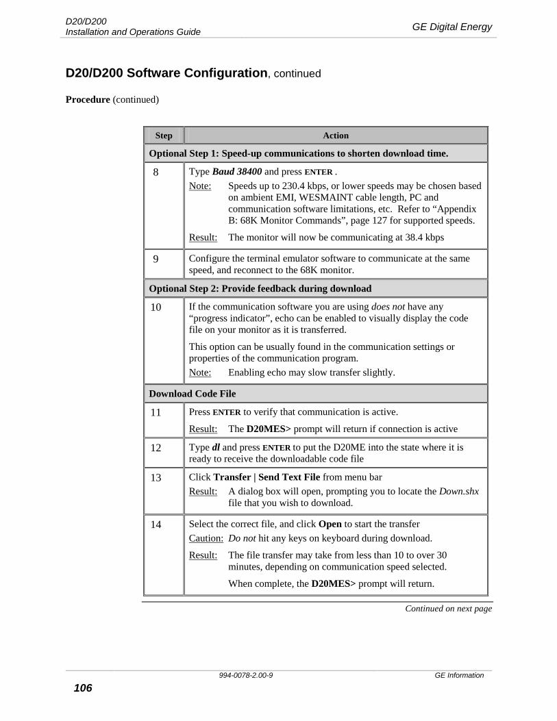
D20/D200 Installation and Operations Guide GE Digital Energy
994-0078-2.00-9 GE Information
106
D20/D200 Software Configuration, continued
Procedure (continued)
Step Action
Optional Step 1: Speed-up communications to shorten download time.
8 Type Baud 38400 and press ENTER . Note: Speeds up to 230.4 kbps, or lower speeds may be chosen based
on ambient EMI, WESMAINT cable length, PC and communication software limitations, etc. Refer to “Appendix B: 68K Monitor Commands”, page 127 for supported speeds.
Result: The monitor will now be communicating at 38.4 kbps
9 Configure the terminal emulator software to communicate at the same speed, and reconnect to the 68K monitor.
Optional Step 2: Provide feedback during download
10 If the communication software you are using does not have any “progress indicator”, echo can be enabled to visually display the code file on your monitor as it is transferred.
This option can be usually found in the communication settings or properties of the communication program. Note: Enabling echo may slow transfer slightly.
Download Code File
11 Press ENTER to verify that communication is active.
Result: The D20MES> prompt will return if connection is active
12 Type dl and press ENTER to put the D20ME into the state where it is ready to receive the downloadable code file
13 Click Transfer | Send Text File from menu bar Result: A dialog box will open, prompting you to locate the Down.shx
file that you wish to download.
14 Select the correct file, and click Open to start the transfer Caution: Do not hit any keys on keyboard during download.
Result: The file transfer may take from less than 10 to over 30 minutes, depending on communication speed selected.
When complete, the D20MES> prompt will return.
Continued on next page
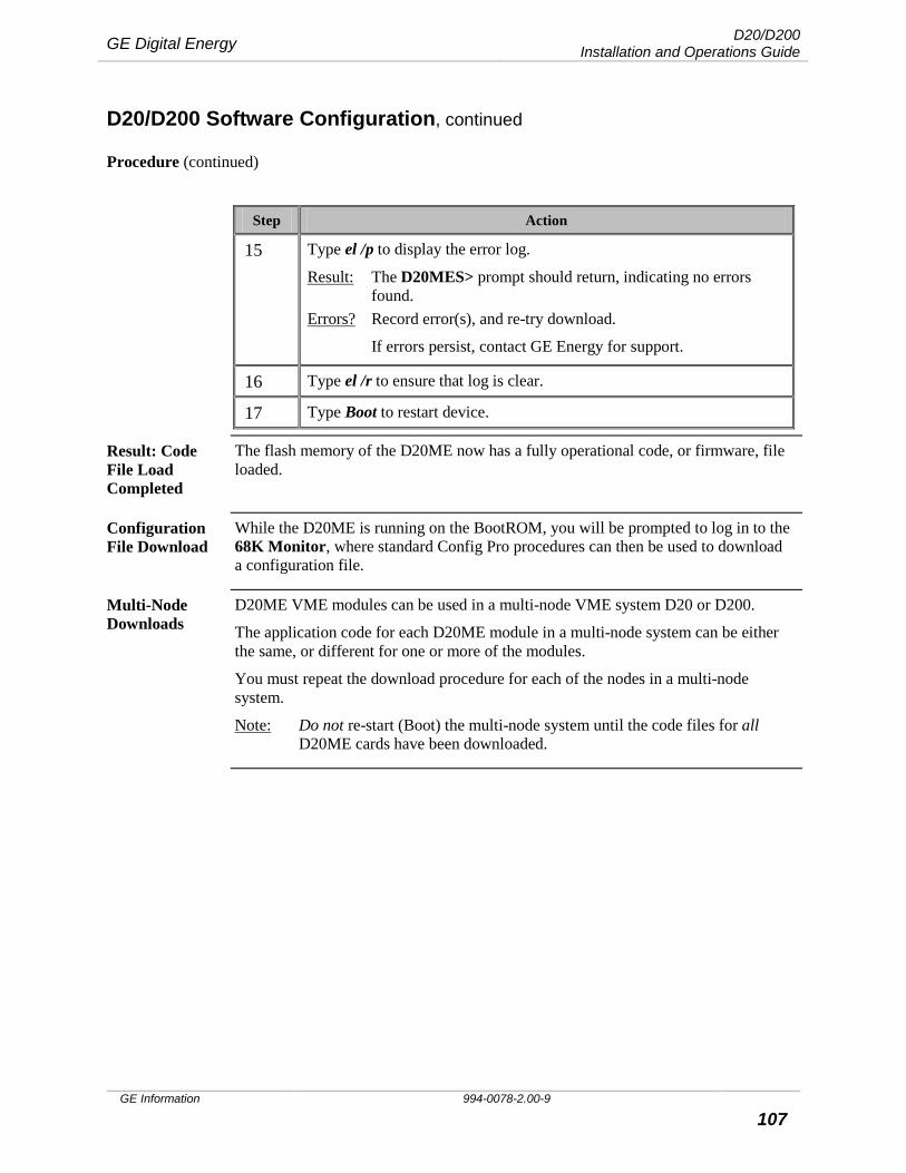
GE Digital Energy D20/D200 Installation and Operations Guide
GE Information 994-0078-2.00-9 107
D20/D200 Software Configuration, continued
Procedure (continued)
Step Action
15 Type el /p to display the error log.
Result: The D20MES> prompt should return, indicating no errors found.
Errors? Record error(s), and re-try download.
If errors persist, contact GE Energy for support.
16 Type el /r to ensure that log is clear.
17 Type Boot to restart device.
Result: Code File Load Completed
The flash memory of the D20ME now has a fully operational code, or firmware, file loaded.
Configuration File Download
While the D20ME is running on the BootROM, you will be prompted to log in to the 68K Monitor, where standard Config Pro procedures can then be used to download a configuration file.
Multi-Node Downloads
D20ME VME modules can be used in a multi-node VME system D20 or D200.
The application code for each D20ME module in a multi-node system can be either the same, or different for one or more of the modules.
You must repeat the download procedure for each of the nodes in a multi-node system.
Note: Do not re-start (Boot) the multi-node system until the code files for all D20ME cards have been downloaded.
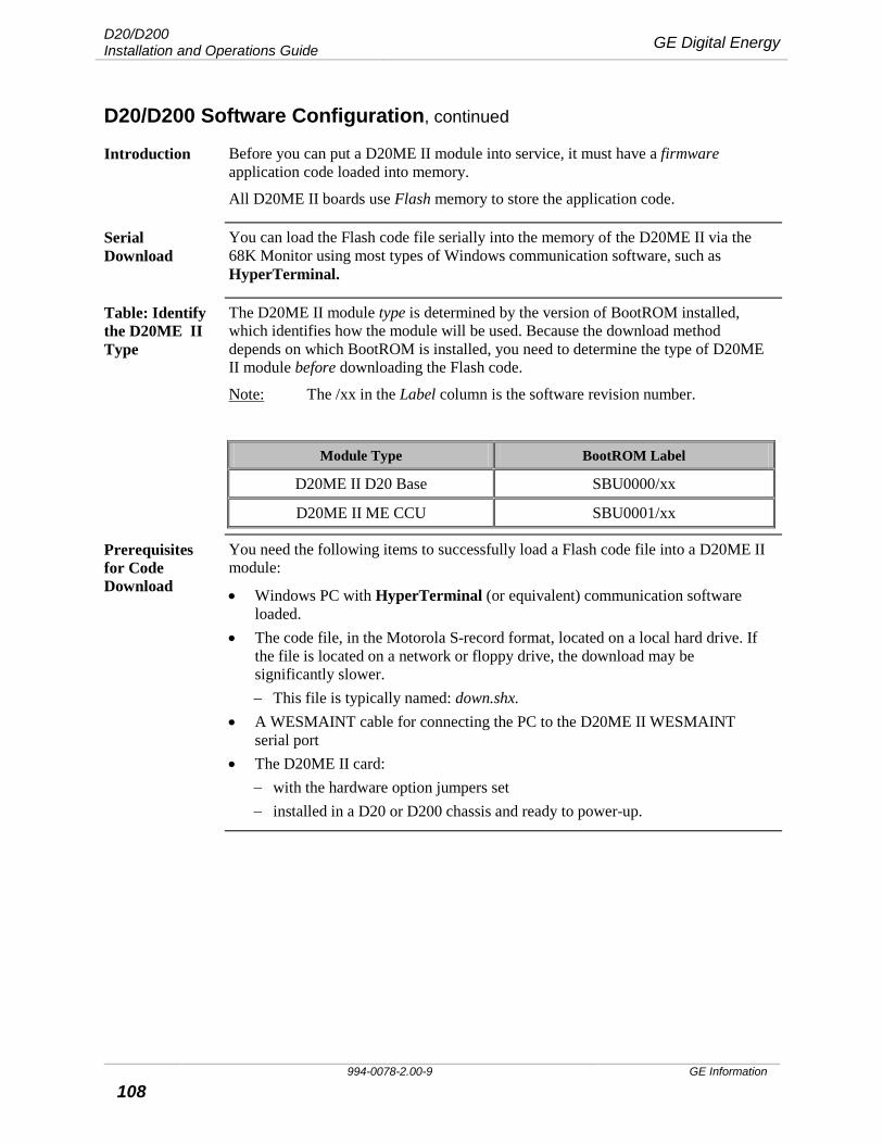
D20/D200 Installation and Operations Guide GE Digital Energy
994-0078-2.00-9 GE Information
108
D20/D200 Software Configuration, continued
Introduction Before you can put a D20ME II module into service, it must have a firmware application code loaded into memory.
All D20ME II boards use Flash memory to store the application code.
Serial Download
You can load the Flash code file serially into the memory of the D20ME II via the 68K Monitor using most types of Windows communication software, such as HyperTerminal.
Table: Identify the D20ME II Type
The D20ME II module type is determined by the version of BootROM installed, which identifies how the module will be used. Because the download method depends on which BootROM is installed, you need to determine the type of D20ME II module before downloading the Flash code.
Note: The /xx in the Label column is the software revision number.
Module Type BootROM Label
D20ME II D20 Base SBU0000/xx
D20ME II ME CCU SBU0001/xx
Prerequisites for Code Download
You need the following items to successfully load a Flash code file into a D20ME II module:
• Windows PC with HyperTerminal (or equivalent) communication software loaded.
• The code file, in the Motorola S-record format, located on a local hard drive. If the file is located on a network or floppy drive, the download may be significantly slower. − This file is typically named: down.shx.
• A WESMAINT cable for connecting the PC to the D20ME II WESMAINT serial port
• The D20ME II card: − with the hardware option jumpers set − installed in a D20 or D200 chassis and ready to power-up.
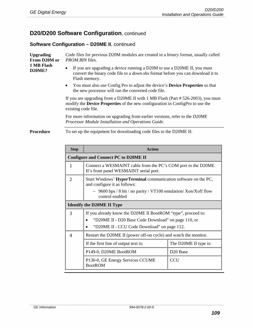
GE Digital Energy D20/D200 Installation and Operations Guide
GE Information 994-0078-2.00-9 109
D20/D200 Software Configuration, continued
Software Configuration – D20ME II, continued
Upgrading From D20M or 1 MB Flash D20ME?
Code files for previous D20M modules are created in a binary format, usually called PROM.BIN files.
• If you are upgrading a device running a D20M to use a D20ME II, you must convert the binary code file to a down.shx format before you can download it to Flash memory.
• You must also use Config Pro to adjust the device’s Device Properties so that the new processor will run the converted code file.
If you are upgrading from a D20ME II with 1 MB Flash (Part # 526-2003), you must modify the Device Properties of the new configuration in ConfigPro to use the existing code file.
For more information on upgrading from earlier versions, refer to the D20ME Processor Module Installation and Operations Guide.
Procedure To set up the equipment for downloading code files to the D20ME II:
Step Action
Configure and Connect PC to D20ME II
1 Connect a WESMAINT cable from the PC’s COM port to the D20ME II’s front panel WESMAINT serial port.
2 Start Windows’ HyperTerminal communication software on the PC, and configure it as follows:
− 9600 bps / 8 bit / no parity / VT100 emulation/ Xon/Xoff flow control enabled
Identify the D20ME II Type
3 If you already know the D20ME II BootROM “type”, proceed to: • “D20ME II - D20 Base Code Download” on page 110, or • “D20ME II - CCU Code Download” on page 112.
4 Restart the D20ME II (power off-on cycle) and watch the monitor.
If the first line of output text is: The D20ME II type is:
P149-0, D20ME BootROM D20 Base
P130-0, GE Energy Services CCUME BootROM
CCU
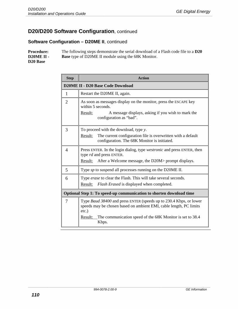
D20/D200 Installation and Operations Guide GE Digital Energy
994-0078-2.00-9 GE Information
110
D20/D200 Software Configuration, continued
Software Configuration – D20ME II, continued
Procedure: D20ME II - D20 Base
The following steps demonstrate the serial download of a Flash code file to a D20 Base type of D20ME II module using the 68K Monitor.
Step Action
D20ME II - D20 Base Code Download
1 Restart the D20ME II, again.
2 As soon as messages display on the monitor, press the ESCAPE key within 5 seconds. Result: A message displays, asking if you wish to mark the
configuration as “bad”.
3 To proceed with the download, type y. Result: The current configuration file is overwritten with a default
configuration. The 68K Monitor is initiated.
4 Press ENTER. In the login dialog, type westronic and press ENTER, then type rd and press ENTER. Result: After a Welcome message, the D20M> prompt displays.
5 Type sp to suspend all processes running on the D20ME II.
6 Type erase to clear the Flash. This will take several seconds. Result: Flash Erased is displayed when completed.
Optional Step 1: To speed-up communication to shorten download time
7 Type Baud 38400 and press ENTER (speeds up to 230.4 Kbps, or lower speeds may be chosen based on ambient EMI, cable length, PC limits etc.) Result: The communication speed of the 68K Monitor is set to 38.4
Kbps.
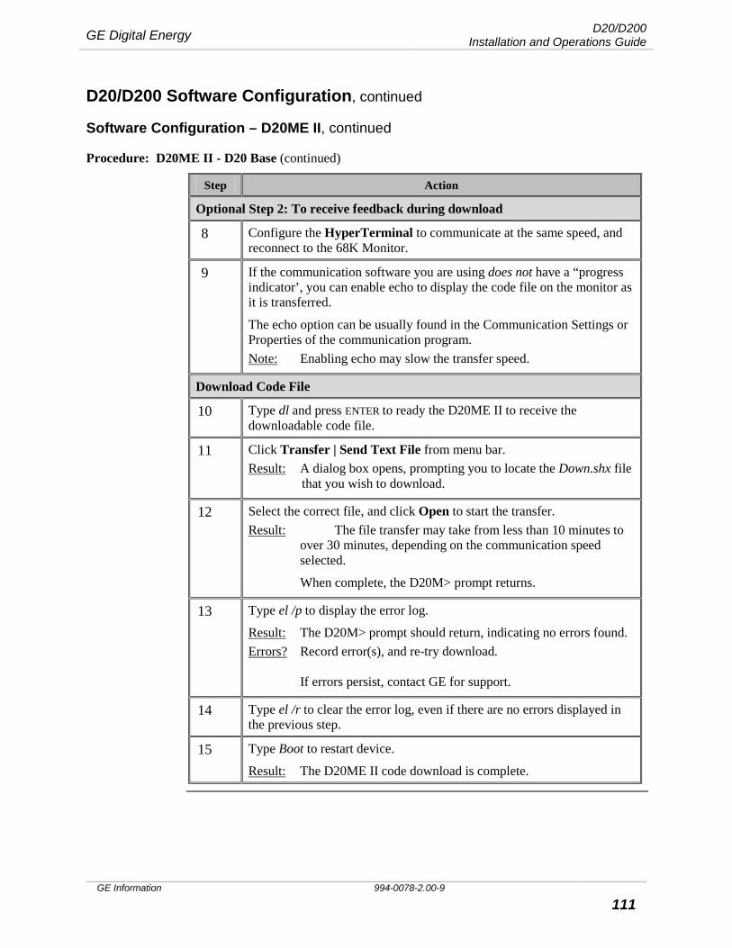
GE Digital Energy D20/D200 Installation and Operations Guide
GE Information 994-0078-2.00-9 111
D20/D200 Software Configuration, continued
Software Configuration – D20ME II, continued
Procedure: D20ME II - D20 Base (continued)
Step Action
Optional Step 2: To receive feedback during download
8 Configure the HyperTerminal to communicate at the same speed, and reconnect to the 68K Monitor.
9 If the communication software you are using does not have a “progress indicator’, you can enable echo to display the code file on the monitor as it is transferred.
The echo option can be usually found in the Communication Settings or Properties of the communication program. Note: Enabling echo may slow the transfer speed.
Download Code File
10 Type dl and press ENTER to ready the D20ME II to receive the downloadable code file.
11 Click Transfer | Send Text File from menu bar. Result: A dialog box opens, prompting you to locate the Down.shx file
that you wish to download.
12 Select the correct file, and click Open to start the transfer. Result: The file transfer may take from less than 10 minutes to
over 30 minutes, depending on the communication speed selected.
When complete, the D20M> prompt returns.
13 Type el /p to display the error log.
Result: The D20M> prompt should return, indicating no errors found. Errors? Record error(s), and re-try download.
If errors persist, contact GE for support.
14 Type el /r to clear the error log, even if there are no errors displayed in the previous step.
15 Type Boot to restart device.
Result: The D20ME II code download is complete.
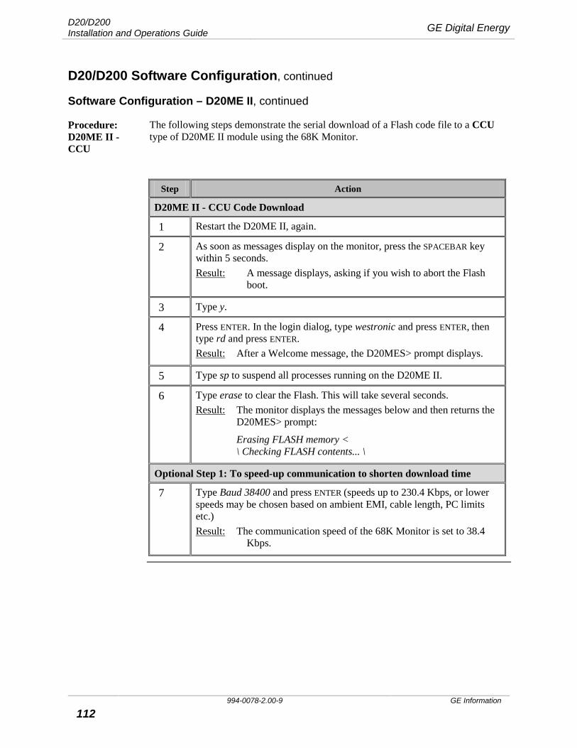
D20/D200 Installation and Operations Guide GE Digital Energy
994-0078-2.00-9 GE Information
112
D20/D200 Software Configuration, continued
Software Configuration – D20ME II, continued
Procedure: D20ME II - CCU
The following steps demonstrate the serial download of a Flash code file to a CCU type of D20ME II module using the 68K Monitor.
Step Action
D20ME II - CCU Code Download
1 Restart the D20ME II, again.
2 As soon as messages display on the monitor, press the SPACEBAR key within 5 seconds. Result: A message displays, asking if you wish to abort the Flash
boot.
3 Type y.
4 Press ENTER. In the login dialog, type westronic and press ENTER, then type rd and press ENTER. Result: After a Welcome message, the D20MES> prompt displays.
5 Type sp to suspend all processes running on the D20ME II.
6 Type erase to clear the Flash. This will take several seconds. Result: The monitor displays the messages below and then returns the
D20MES> prompt:
Erasing FLASH memory < \ Checking FLASH contents... \
Optional Step 1: To speed-up communication to shorten download time
7 Type Baud 38400 and press ENTER (speeds up to 230.4 Kbps, or lower speeds may be chosen based on ambient EMI, cable length, PC limits etc.) Result: The communication speed of the 68K Monitor is set to 38.4
Kbps.
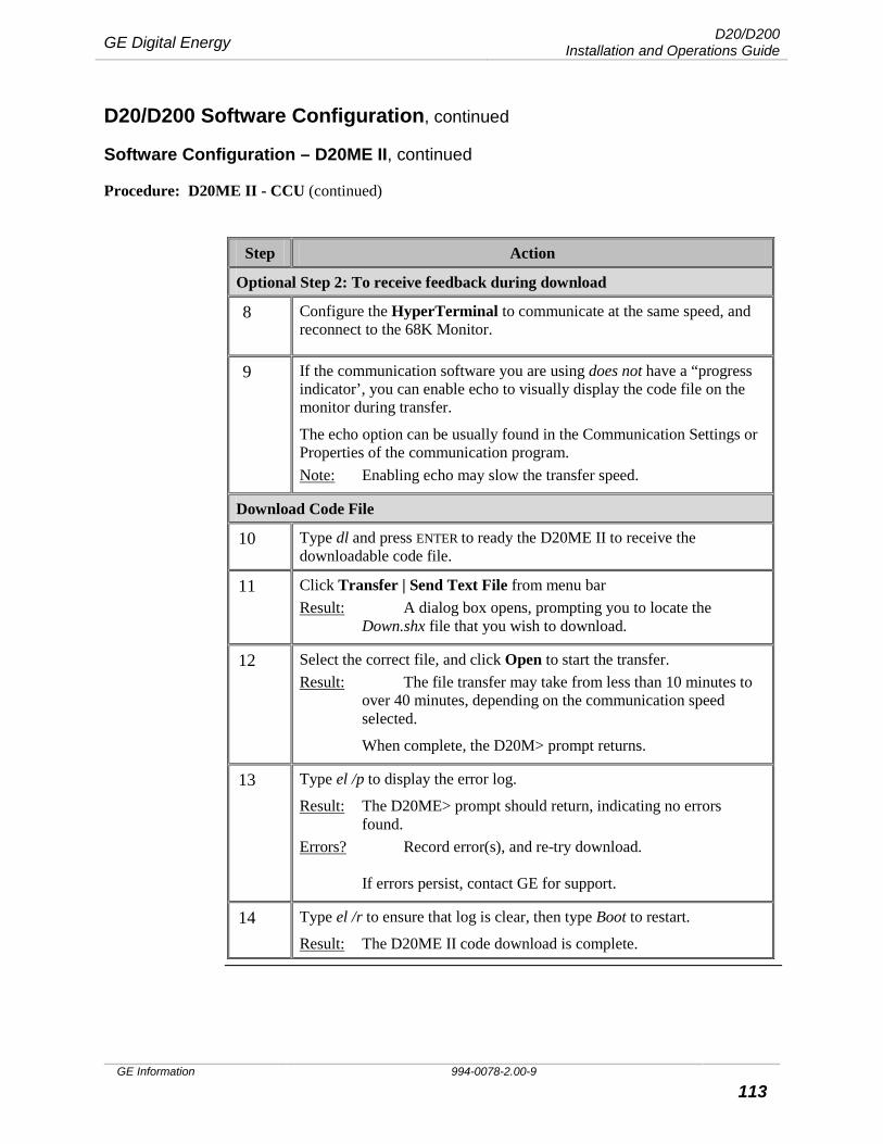
GE Digital Energy D20/D200 Installation and Operations Guide
GE Information 994-0078-2.00-9 113
D20/D200 Software Configuration, continued
Software Configuration – D20ME II, continued
Procedure: D20ME II - CCU (continued)
Step Action
Optional Step 2: To receive feedback during download
8 Configure the HyperTerminal to communicate at the same speed, and reconnect to the 68K Monitor.
9 If the communication software you are using does not have a “progress indicator’, you can enable echo to visually display the code file on the monitor during transfer.
The echo option can be usually found in the Communication Settings or Properties of the communication program. Note: Enabling echo may slow the transfer speed.
Download Code File
10 Type dl and press ENTER to ready the D20ME II to receive the downloadable code file.
11 Click Transfer | Send Text File from menu bar Result: A dialog box opens, prompting you to locate the
Down.shx file that you wish to download.
12 Select the correct file, and click Open to start the transfer. Result: The file transfer may take from less than 10 minutes to
over 40 minutes, depending on the communication speed selected.
When complete, the D20M> prompt returns.
13 Type el /p to display the error log.
Result: The D20ME> prompt should return, indicating no errors found. Errors? Record error(s), and re-try download.
If errors persist, contact GE for support.
14 Type el /r to ensure that log is clear, then type Boot to restart.
Result: The D20ME II code download is complete.
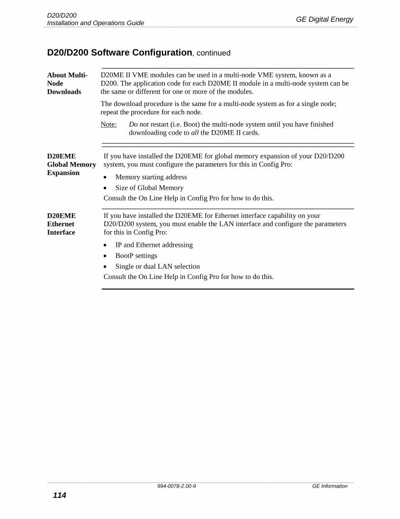
D20/D200 Installation and Operations Guide GE Digital Energy
994-0078-2.00-9 GE Information
114
D20/D200 Software Configuration, continued
About Multi-Node Downloads
D20ME II VME modules can be used in a multi-node VME system, known as a D200. The application code for each D20ME II module in a multi-node system can be the same or different for one or more of the modules.
The download procedure is the same for a multi-node system as for a single node; repeat the procedure for each node.
Note: Do not restart (i.e. Boot) the multi-node system until you have finished downloading code to all the D20ME II cards.
D20EME Global Memory Expansion
If you have installed the D20EME for global memory expansion of your D20/D200 system, you must configure the parameters for this in Config Pro:
• Memory starting address • Size of Global Memory Consult the On Line Help in Config Pro for how to do this.
D20EME Ethernet Interface
If you have installed the D20EME for Ethernet interface capability on your D20/D200 system, you must enable the LAN interface and configure the parameters for this in Config Pro:
• IP and Ethernet addressing • BootP settings • Single or dual LAN selection Consult the On Line Help in Config Pro for how to do this.
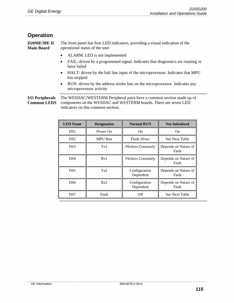
GE Digital Energy D20/D200 Installation and Operations Guide
GE Information 994-0078-2.00-9 115
Operation D20ME/ME II Main Board
The front panel has four LED indicators, providing a visual indication of the operational status of the unit:
• ALARM: LED is not implemented • FAIL: driven by a programmed signal. Indicates that diagnostics are running or
have failed • HALT: driven by the halt line input of the microprocessor. Indicates that MPU
has stopped • RUN: driven by the address strobe line on the microprocessor. Indicates any
microprocessor activity
I/O Peripherals Common LEDS
The WESDAC/WESTERM Peripheral pairs have a common section made up of components on the WESDAC and WESTERM boards. There are seven LED indicators on this common section.
LED Name Designation Normal RUN Not Initialized
DS1 Power On On On
DS2 MPU Run Flash 10/sec See Next Table
DS3 Tx1 Flickers Constantly Depends on Nature of Fault
DS4 Rx1 Flickers Constantly Depends on Nature of Fault
DS5 Tx2 Configuration Dependent
Depends on Nature of Fault
DS6 Rx2 Configuration Dependent
Depends on Nature of Fault
DS7 Fault Off See Next Table

D20/D200 Installation and Operations Guide GE Digital Energy
994-0078-2.00-9 GE Information
116
Operation, continued
LEDs vs. MCU Status
The MPU Run and Fault LEDs, DS2 and DS7, together indicate the MCU’s operating status.
MPU Run LED Fault LED Flash Period
(s)
MCU Operating Status
Flash Off 0.1 Applications downloaded and operating
Flash Off 0.75 Applications downloaded but not operating
Flash (alternating)
Flash (alternating)
0.75 Applications not downloaded and only ROM operating
Off Flash 0.5 EPROM checksum error
Flash (simultaneously)
Flash (simultaneously)
0.5 RAM error: device address error
D20 Power Supply LEDs
On the chassis-mounted D20 Power Supplies there are LED indicators for each of the supply voltages. The indicators are illuminated green when that voltage is present.
D20EME LEDs The following table explains the operational function of the four LED indicators:
Name Function
BATT 1 LED Lights when battery voltage drops below 3 Volts. Replace battery immediately.
BATT 2 LED
POWER LED +5 Volts power is available.
ACCESS LED Indicates D20EME is being accessed from VME bus.
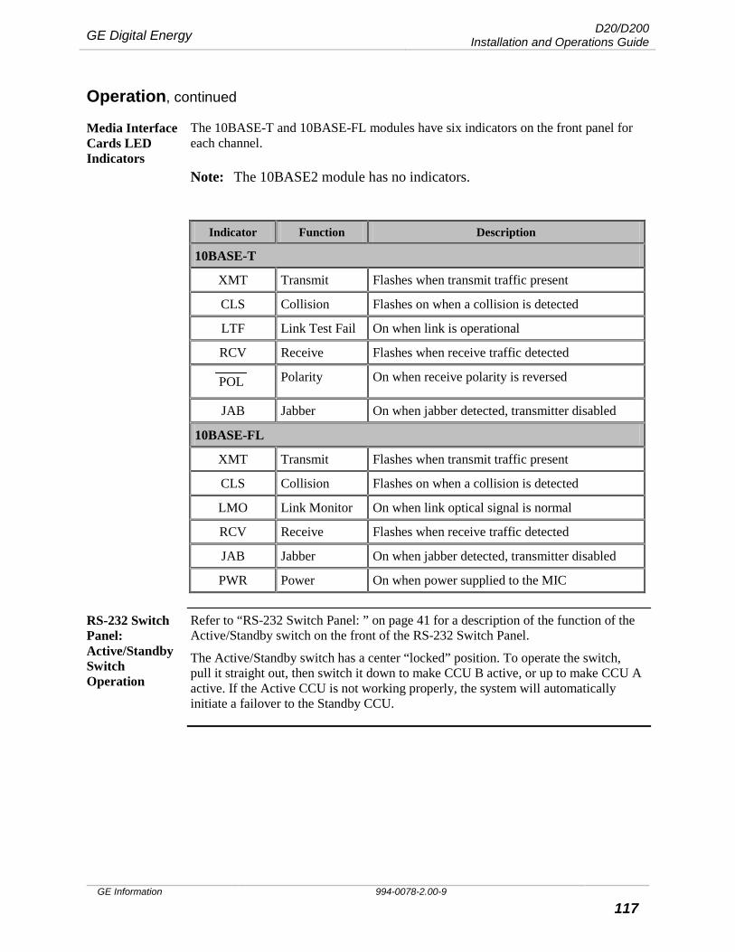
GE Digital Energy D20/D200 Installation and Operations Guide
GE Information 994-0078-2.00-9 117
Operation, continued
Media Interface Cards LED Indicators
The 10BASE-T and 10BASE-FL modules have six indicators on the front panel for each channel.
Note: The 10BASE2 module has no indicators.
Indicator Function Description
10BASE-T
XMT Transmit Flashes when transmit traffic present
CLS Collision Flashes on when a collision is detected
LTF Link Test Fail On when link is operational
RCV Receive Flashes when receive traffic detected
POL Polarity On when receive polarity is reversed
JAB Jabber On when jabber detected, transmitter disabled
10BASE-FL
XMT Transmit Flashes when transmit traffic present
CLS Collision Flashes on when a collision is detected
LMO Link Monitor On when link optical signal is normal
RCV Receive Flashes when receive traffic detected
JAB Jabber On when jabber detected, transmitter disabled
PWR Power On when power supplied to the MIC
RS-232 Switch Panel: Active/Standby Switch Operation
Refer to “RS-232 Switch Panel: ” on page 41 for a description of the function of the Active/Standby switch on the front of the RS-232 Switch Panel.
The Active/Standby switch has a center “locked” position. To operate the switch, pull it straight out, then switch it down to make CCU B active, or up to make CCU A active. If the Active CCU is not working properly, the system will automatically initiate a failover to the Standby CCU.
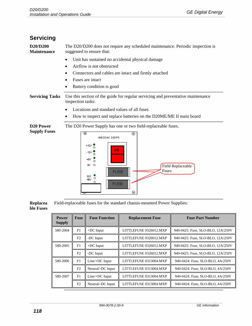
D20/D200 Installation and Operations Guide GE Digital Energy
994-0078-2.00-9 GE Information
118
Servicing D20/D200 Maintenance
The D20/D200 does not require any scheduled maintenance. Periodic inspection is suggested to ensure that:
• Unit has sustained no accidental physical damage • Airflow is not obstructed • Connectors and cables are intact and firmly attached • Fuses are intact • Battery condition is good
Servicing Tasks Use this section of the guide for regular servicing and preventative maintenance inspection tasks:
• Locations and standard values of all fuses • How to inspect and replace batteries on the D20ME/ME II main board
D20 Power Supply Fuses
The D20 Power Supply has one or two field-replaceable fuses.
Replaceable Fuses
Field-replaceable fuses for the standard chassis-mounted Power Supplies:
Power Supply
Fuse Fuse Function Replacement Fuse Fuse Part Number
580-2004 F1 +DC Input LITTLEFUSE 0326012.MXP 940-0425: Fuse, SLO-BLO, 12A/250V
F2 -DC Input LITTLEFUSE 0326012.MXP 940-0425: Fuse, SLO-BLO, 12A/250V
580-2005 F1 +DC Input LITTLEFUSE 0326012.MXP 940-0425: Fuse, SLO-BLO, 12A/250V
F2 -DC Input LITTLEFUSE 0326012.MXP 940-0425: Fuse, SLO-BLO, 12A/250V
580-2006 F1 Line/+DC Input LITTLEFUSE 0313004.MXP 940-0424: Fuse, SLO-BLO, 4A/250V
F2 Neutral/-DC Input LITTLEFUSE 0313004.MXP 940-0424: Fuse, SLO-BLO, 4A/250V
580-2007 F1 Line/+DC Input LITTLEFUSE 0313004.MXP 940-0424: Fuse, SLO-BLO, 4A/250V
F2 Neutral/-DC Input LITTLEFUSE 0313004.MXP 940-0424: Fuse, SLO-BLO, 4A/250V
Field Replaceable Fuses Field Replaceable Fuses
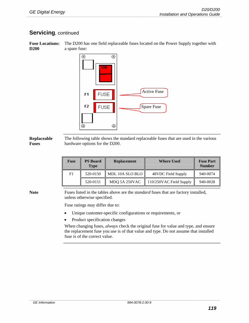
GE Digital Energy D20/D200 Installation and Operations Guide
GE Information 994-0078-2.00-9 119
Servicing, continued
Fuse Locations: D200
The D200 has one field replaceable fuses located on the Power Supply together with a spare fuse:
Replaceable Fuses
The following table shows the standard replaceable fuses that are used in the various hardware options for the D200.
Fuse PS Board Type
Replacement Where Used Fuse Part Number
F1 520-0150 MDL 10A SLO BLO 48VDC Field Supply 940-0074
520-0151 MDQ 5A 250VAC 110/250VAC Field Supply 940-0028
Note Fuses listed in the tables above are the standard fuses that are factory installed, unless otherwise specified.
Fuse ratings may differ due to:
• Unique customer-specific configurations or requirements, or • Product specification changes When changing fuses, always check the original fuse for value and type, and ensure the replacement fuse you use is of that value and type. Do not assume that installed fuse is of the correct value.
Spare Fuse
Active Fuse
D20/D200 Installation and Operations Guide GE Digital Energy
994-0078-2.00-9 GE Information
120
Servicing, continued
Batteries The D20ME/ME II Main board has two lithium batteries located near the front of the board. These maintain the contents of the NVRAM in the event that power is removed from the module. See “D20ME Main Module: Board Layout” page 42.
Battery life should exceed five years:
• If the D20ME is never powered down, or • If the batteries are disconnected, by removing jumper JP8 Battery life is shortened if they are left connected while the D20ME is powered down for extended periods.
Battery Checking
To check battery voltage, use a meter or other measuring device that has high input impedance. (10MΩ or higher)
The batteries have a nominal voltage of 3.6 volts. Batteries with a voltage of 3.0 volts or less should be changed.
!
• If you remove one or both of the batteries from the D20ME, configuration data and any other database information stored in NVRAM is lost.
• You have to download the configuration file after battery changing to restore operation.
Cleaning & Handling of Batteries
• Use non-conductive cleaning solution to prevent battery performance deterioration.
• Dry batteries at a temperature below 85° C to prevent seal deformation, which may result in leakage.
• Avoid: − inversion of polarity − exposure to high temperatures, such as soldering or spot-welding − excessive force to terminals
• Wear gloves or finger caps when handling batteries to keep them clean. • For long-term storage,
− keep at temperatures and humidity below normal − avoid shorting or loading while stored.
!
• There are many electronic components near the battery that are sensitive to electrostatic discharge
• Observe extreme caution and proper procedures when servicing components that are sensitive to electrostatic discharge
GE Digital Energy D20/D200 Installation and Operations Guide
GE Information 994-0078-2.00-9 121
Servicing, continued
!
Do not disassemble, crush, puncture, or incinerate the battery.
Handle a damaged or leaking battery with extreme care. If you touch the electrolyte, wash the exposed skin with soap and water. If the electrolyte contacts your eye, flush the eye with water for 15 minutes. If you have inhaled the electrolyte, move to fresh air, and monitor breathing and circulation. In each case, seek immediate medical attention.
Recycling of Batteries
The D20ME lithium battery is recyclable and does not contain mercury, cadmium, or lead in levels above those regulated by the European Union. Recycle the battery according to local waste management regulations.
In accordance with European Directive 2006/66/EC, batteries are marked with the crossed out wheeled bin, which indicates that they cannot be disposed of as unsorted municipal waste in the European Union. Users of batteries must use the collection points available to customers for the return, recycling, and treatment of batteries. Customer participation is important to minimize the negative effects of batteries to the environment and sustain available natural resources. For more information see www.weeerohsinfo.com.
Procedure: Change Battery
To change each D20ME battery, follow these steps:
Note: It is recommended that both batteries be changed as a set.
Step Action
Battery Removal
1 Using a plastic or other non-conductive tool, pry the black plastic retaining clip holding the battery away from the battery holder.
2 When free, the battery and clip can be removed together.
Result: The battery and clips are removed.
3 Remove the clip from the battery.
Battery Replacement
4 Place new battery into battery holder, carefully noting proper polarity.
5 Replace retaining clip across the center of the battery, and press down until it clicks into the retaining notches in the battery holder.
6 Repeat steps 1 through 5 for other battery.
Result: New batteries are installed.
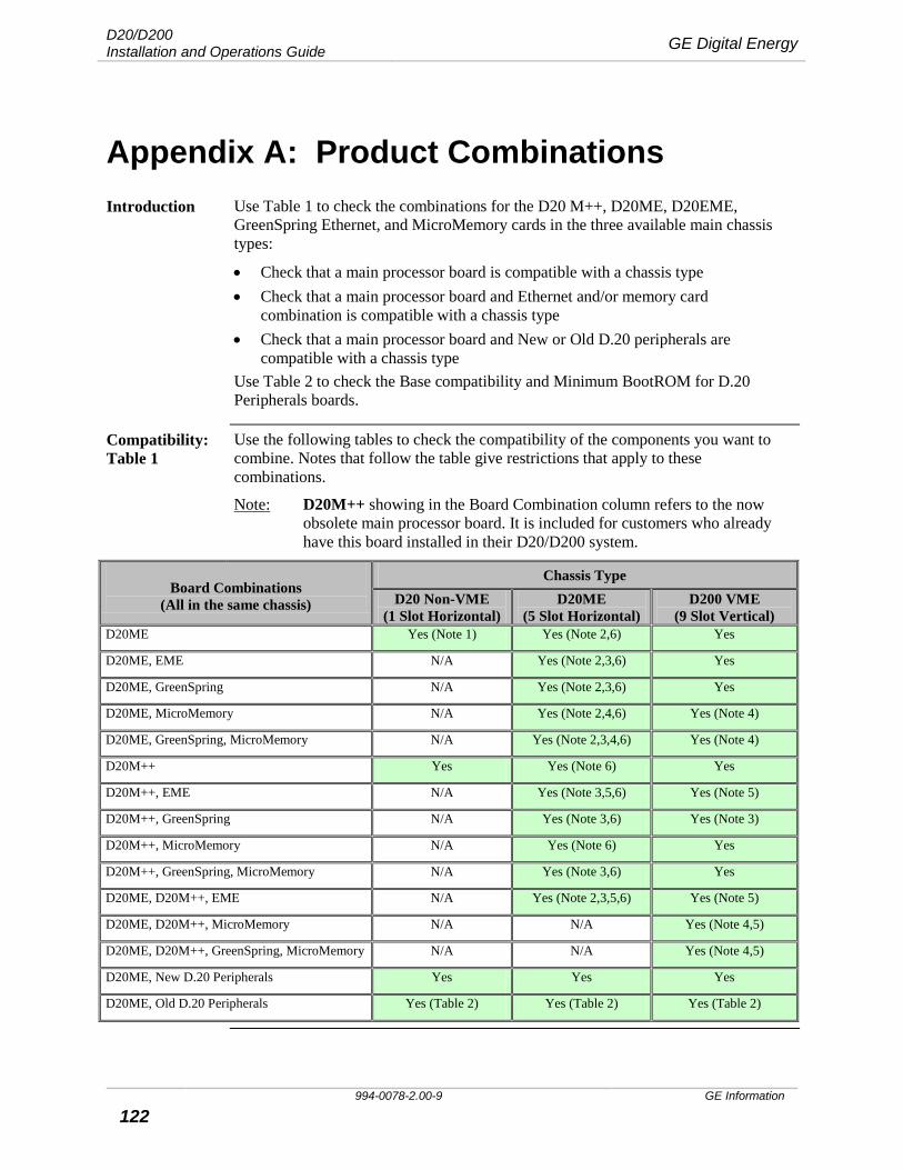
D20/D200 Installation and Operations Guide GE Digital Energy
994-0078-2.00-9 GE Information
122
Appendix A: Product Combinations Introduction Use Table 1 to check the combinations for the D20 M++, D20ME, D20EME,
GreenSpring Ethernet, and MicroMemory cards in the three available main chassis types:
• Check that a main processor board is compatible with a chassis type • Check that a main processor board and Ethernet and/or memory card
combination is compatible with a chassis type • Check that a main processor board and New or Old D.20 peripherals are
compatible with a chassis type Use Table 2 to check the Base compatibility and Minimum BootROM for D.20 Peripherals boards.
Compatibility: Table 1
Use the following tables to check the compatibility of the components you want to combine. Notes that follow the table give restrictions that apply to these combinations.
Note: D20M++ showing in the Board Combination column refers to the now obsolete main processor board. It is included for customers who already have this board installed in their D20/D200 system.
Board Combinations
(All in the same chassis)
Chassis Type D20 Non-VME
(1 Slot Horizontal) D20ME
(5 Slot Horizontal) D200 VME
(9 Slot Vertical) D20ME Yes (Note 1) Yes (Note 2,6) Yes
D20ME, EME N/A Yes (Note 2,3,6) Yes
D20ME, GreenSpring N/A Yes (Note 2,3,6) Yes
D20ME, MicroMemory N/A Yes (Note 2,4,6) Yes (Note 4)
D20ME, GreenSpring, MicroMemory N/A Yes (Note 2,3,4,6) Yes (Note 4)
D20M++ Yes Yes (Note 6) Yes
D20M++, EME N/A Yes (Note 3,5,6) Yes (Note 5)
D20M++, GreenSpring N/A Yes (Note 3,6) Yes (Note 3)
D20M++, MicroMemory N/A Yes (Note 6) Yes
D20M++, GreenSpring, MicroMemory N/A Yes (Note 3,6) Yes
D20ME, D20M++, EME N/A Yes (Note 2,3,5,6) Yes (Note 5)
D20ME, D20M++, MicroMemory N/A N/A Yes (Note 4,5)
D20ME, D20M++, GreenSpring, MicroMemory N/A N/A Yes (Note 4,5)
D20ME, New D.20 Peripherals Yes Yes Yes
D20ME, Old D.20 Peripherals Yes (Table 2) Yes (Table 2) Yes (Table 2)
GE Digital Energy D20/D200 Installation and Operations Guide
GE Information 994-0078-2.00-9 123
Product Combinations, continued Notes 1. Not all non-VME backplanes pass: use 517-0224-05A, 517-0254-02 or newer.
The VME D20ME, 526-2005, does NOT work with non-VME backplanes. You must use the non-VME D20ME, 526-2004.
2. Not all SIO communication panels pass: use 517-0225-09 or newer. The non-VME D20ME, 526-2004, does NOT work with VME backplanes. You must use the VME D20ME, 526-2005.
3. Ethernet cards should only be installed in the new D20 MX Chassis, or a D200 chassis. Older D20 horizontal chassis have no place for the interface cable between the D20EME and the MIC to run inside the chassis. Although you can physically bring this cable out the back of the chassis between the metalwork and the PCB, it invalidates the compliance to industrial emissions standards.
4. Do not use 16MB Micro Memory cards with the D20ME. Use 8MB card(s) as required. 16MB Micro Memory cards can be used with D20M++ cards.
5. D20 M++ cards cannot be used with D20ME or D20EME cards in systems with more than three processor boards. Occasional crashes can occur in these systems.
6. There are some limitations to the number of nodes you can have in a D20 VME Chassis: − Due to the mounting arrangement of the Serial I/O communications interface
panel on a D20 chassis, it is not always practical to have more than one node. On the 500-0280 MX Chassis you can have one rack mounted com panel (517-0225) and one rear mounted com panel (571-0230), supplying physical com channels for two processor nodes. Additional nodes could be dedicated to Ethernet and automation applications if desired.
− The D20 Power Supply +5V output can supply up to 5A. Each D20ME requires 1A, and the D20EME requires 110mA. The remaining power can be used to line power 5V devices on the RS-232 communication ports. This means the D20 Power Supply can power up to 4 D20ME cards and 1 D20EME.
− The D20 Power Supply +12V output can supply a maximum of 1A. The D20EME requires 0.6A. The remaining power can be used to line power 12V devices on the RS-232 communication ports. In practice, this means that the D20 Power Supply can power either a D20EME, or a few modems. If both Ethernet and modems, or several modems, are required then an external 12V power supply is generally required. Common Power Consumption Ratings: • D20EME w/ MIC 0.60A @ +12V • D20ME 0.10A @ +12V • WESDAC 202 Modem 0.10A @ +12V • Telenetics® Modem 0.35A @ +12V
Example: 1 D20ME, 1 D20EME w/ 10BaseT, and 1 Telenetics Modem exceeds the available +12V Capacity
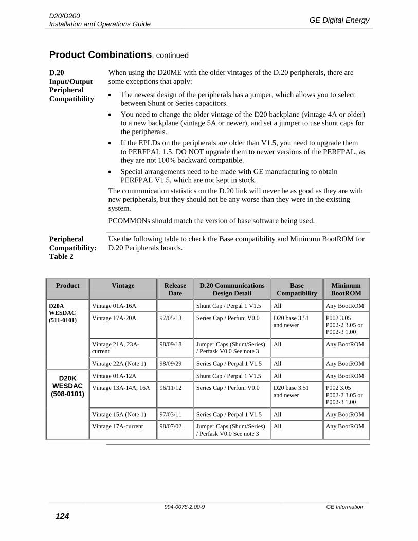
D20/D200 Installation and Operations Guide GE Digital Energy
994-0078-2.00-9 GE Information
124
Product Combinations, continued
D.20 Input/Output Peripheral Compatibility
When using the D20ME with the older vintages of the D.20 peripherals, there are some exceptions that apply:
• The newest design of the peripherals has a jumper, which allows you to select between Shunt or Series capacitors.
• You need to change the older vintage of the D20 backplane (vintage 4A or older) to a new backplane (vintage 5A or newer), and set a jumper to use shunt caps for the peripherals.
• If the EPLDs on the peripherals are older than V1.5, you need to upgrade them to PERFPAL 1.5. DO NOT upgrade them to newer versions of the PERFPAL, as they are not 100% backward compatible.
• Special arrangements need to be made with GE manufacturing to obtain PERFPAL V1.5, which are not kept in stock.
The communication statistics on the D.20 link will never be as good as they are with new peripherals, but they should not be any worse than they were in the existing system.
PCOMMONs should match the version of base software being used.
Peripheral Compatibility: Table 2
Use the following table to check the Base compatibility and Minimum BootROM for D.20 Peripherals boards.
Product Vintage Release Date
D.20 Communications Design Detail
Base Compatibility
Minimum BootROM
D20A WESDAC (511-0101)
Vintage 01A-16A Shunt Cap / Perpal 1 V1.5 All Any BootROM
Vintage 17A-20A 97/05/13 Series Cap / Perfuni V0.0 D20 base 3.51 and newer
P002 3.05 P002-2 3.05 or P002-3 1.00
Vintage 21A, 23A-current
98/09/18 Jumper Caps (Shunt/Series) / Perfask V0.0 See note 3
All Any BootROM
Vintage 22A (Note 1) 98/09/29 Series Cap / Perpal 1 V1.5 All Any BootROM
D20K WESDAC (508-0101)
Vintage 01A-12A Shunt Cap / Perpal 1 V1.5 All Any BootROM
Vintage 13A-14A, 16A 96/11/12 Series Cap / Perfuni V0.0 D20 base 3.51 and newer
P002 3.05 P002-2 3.05 or P002-3 1.00
Vintage 15A (Note 1) 97/03/11 Series Cap / Perpal 1 V1.5 All Any BootROM
Vintage 17A-current 98/07/02 Jumper Caps (Shunt/Series) / Perfask V0.0 See note 3
All Any BootROM
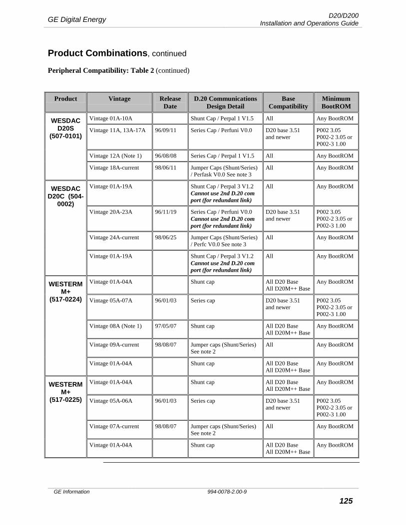
GE Digital Energy D20/D200 Installation and Operations Guide
GE Information 994-0078-2.00-9 125
Product Combinations, continued
Peripheral Compatibility: Table 2 (continued)
Product Vintage Release Date
D.20 Communications Design Detail
Base Compatibility
Minimum BootROM
WESDAC D20S
(507-0101)
Vintage 01A-10A Shunt Cap / Perpal 1 V1.5 All Any BootROM
Vintage 11A, 13A-17A 96/09/11 Series Cap / Perfuni V0.0 D20 base 3.51 and newer
P002 3.05 P002-2 3.05 or P002-3 1.00
Vintage 12A (Note 1) 96/08/08 Series Cap / Perpal 1 V1.5 All Any BootROM
Vintage 18A-current 98/06/11 Jumper Caps (Shunt/Series) / Perfask V0.0 See note 3
All Any BootROM
WESDAC D20C (504-
0002)
Vintage 01A-19A Shunt Cap / Perpal 3 V1.2 Cannot use 2nd D.20 com port (for redundant link)
All Any BootROM
Vintage 20A-23A 96/11/19 Series Cap / Perfuni V0.0 Cannot use 2nd D.20 com port (for redundant link)
D20 base 3.51 and newer
P002 3.05 P002-2 3.05 or P002-3 1.00
Vintage 24A-current 98/06/25 Jumper Caps (Shunt/Series) / Perfc V0.0 See note 3
All Any BootROM
Vintage 01A-19A Shunt Cap / Perpal 3 V1.2 Cannot use 2nd D.20 com port (for redundant link)
All Any BootROM
WESTERM M+
(517-0224)
Vintage 01A-04A Shunt cap All D20 Base All D20M++ Base
Any BootROM
Vintage 05A-07A 96/01/03 Series cap D20 base 3.51 and newer
P002 3.05 P002-2 3.05 or P002-3 1.00
Vintage 08A (Note 1) 97/05/07 Shunt cap All D20 Base All D20M++ Base
Any BootROM
Vintage 09A-current 98/08/07 Jumper caps (Shunt/Series) See note 2
All Any BootROM
Vintage 01A-04A Shunt cap All D20 Base All D20M++ Base
Any BootROM
WESTERM M+
(517-0225)
Vintage 01A-04A Shunt cap All D20 Base All D20M++ Base
Any BootROM
Vintage 05A-06A 96/01/03 Series cap D20 base 3.51 and newer
P002 3.05 P002-2 3.05 or P002-3 1.00
Vintage 07A-current 98/08/07 Jumper caps (Shunt/Series) See note 2
All Any BootROM
Vintage 01A-04A Shunt cap All D20 Base All D20M++ Base
Any BootROM
D20/D200 Installation and Operations Guide GE Digital Energy
994-0078-2.00-9 GE Information
126
Product Combinations, continued
Notes 1. Temporary Vintage (limited distribution)
2. Selection for Shunt or Series capacitor is made using a jumper setting.
3. Selection is made using a combination jumper setting: (i) for a Shunt or Series capacitor and (ii) for an EPLD.
GE Digital Energy D20/D200 Installation and Operations Guide
GE Information 994-0078-2.00-9 127
Appendix B: 68K Monitor Commands Introduction This appendix outlines some of the 68K Monitor commands that can be used when
working with D20ME. Instructions in this chapter are excerpts from the 68K Monitor User's Guide. Refer to the 68K Monitor User's Guide (P136-0UG) for information about other commands not listed here.
Changing the Baud Rate
The D20ME/ME II Monitor has the ability to change the communication speed of the WESMAINT port. This is useful when downloading large files.
Example: A 1 MB code file may take upwards of 40 minutes to download at 9600 bps (the default). At 38400 bps, the transfer is only 10 – 15 minutes.
Note: Most PCs cannot exceed 115,200 bps, and some terminal programs (Windows Terminal for example) may have other restrictions. Check the program's User's Guide for help.
SET BAUD RATE command
The SET BAUD RATE command changes the data rate of the WESMAINT port to a user-supplied value.
Command Format BAUD baud_rate
Variables None
Parameters baud_rate = the new data rate for the port, in bps.
Example Type BAUD 4800 and press ENTER. Results: The monitor switches to communicate at 4800 bps.
Special Considerations
See warning above.
WARNING: Speed change made using the SET BAUD RATE command are not saved in NVRAM; the monitor will return to 9600 bps after a restart. It is recommended that this command be only used to speed up a serial download, and not to redefine the operational state.
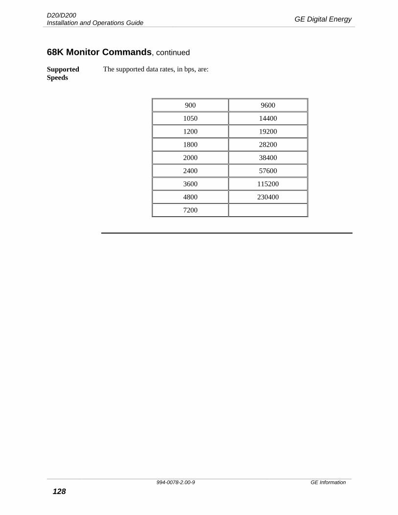
D20/D200 Installation and Operations Guide GE Digital Energy
994-0078-2.00-9 GE Information
128
68K Monitor Commands, continued
Supported Speeds
The supported data rates, in bps, are:
900 9600
1050 14400
1200 19200
1800 28200
2000 38400
2400 57600
3600 115200
4800 230400
7200
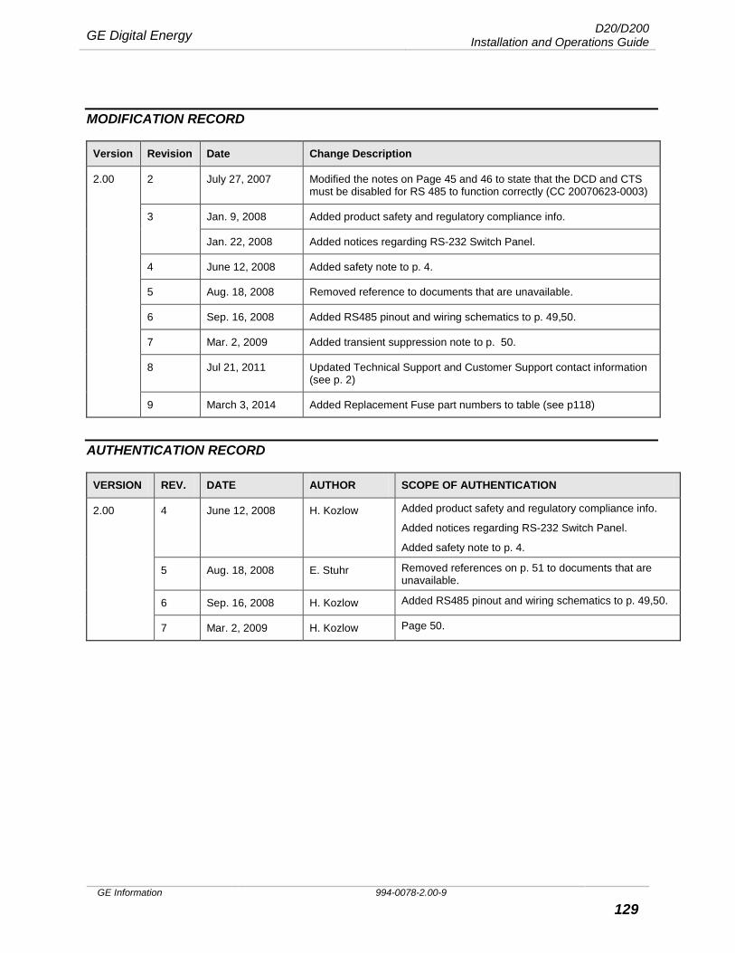
GE Digital Energy D20/D200 Installation and Operations Guide
GE Information 994-0078-2.00-9 129
MODIFICATION RECORD
Version Revision Date Change Description
2.00 2 July 27, 2007 Modified the notes on Page 45 and 46 to state that the DCD and CTS must be disabled for RS 485 to function correctly (CC 20070623-0003)
3 Jan. 9, 2008 Added product safety and regulatory compliance info.
Jan. 22, 2008 Added notices regarding RS-232 Switch Panel.
4 June 12, 2008 Added safety note to p. 4.
5 Aug. 18, 2008 Removed reference to documents that are unavailable.
6 Sep. 16, 2008 Added RS485 pinout and wiring schematics to p. 49,50.
7 Mar. 2, 2009 Added transient suppression note to p. 50.
8 Jul 21, 2011 Updated Technical Support and Customer Support contact information (see p. 2)
9 March 3, 2014 Added Replacement Fuse part numbers to table (see p118)
AUTHENTICATION RECORD
VERSION REV. DATE AUTHOR SCOPE OF AUTHENTICATION
2.00 4 June 12, 2008 H. Kozlow Added product safety and regulatory compliance info.
Added notices regarding RS-232 Switch Panel.
Added safety note to p. 4.
5 Aug. 18, 2008 E. Stuhr Removed references on p. 51 to documents that are unavailable.
6 Sep. 16, 2008 H. Kozlow Added RS485 pinout and wiring schematics to p. 49,50.
7 Mar. 2, 2009 H. Kozlow Page 50.