Embed Size (px)
Citation preview

GPH®
KATALOG/CATALOGUE
VERBINDUNGS- UND ANSCHLUSSTECHNIK • WERKZEUGECONNECTION TECHNOLOGY • TOOLS
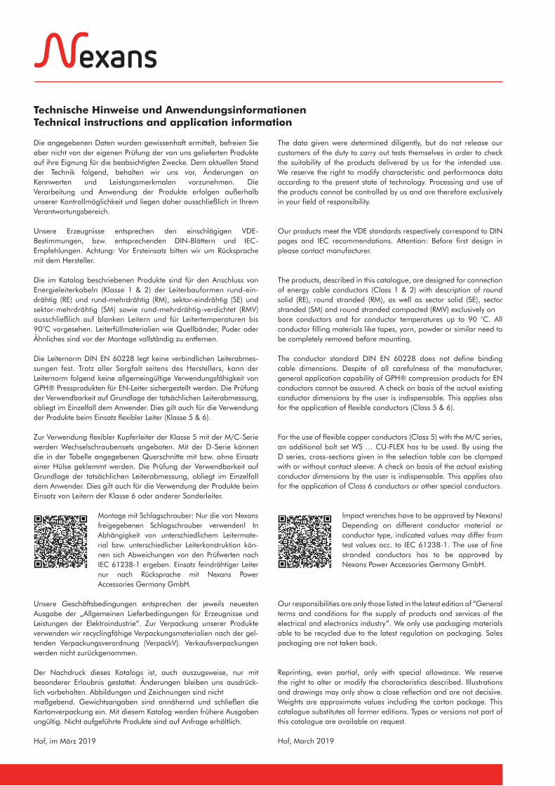
Technische Hinweise und AnwendungsinformationenTechnical instructions and application information
Die angegebenen Daten wurden gewissenhaft ermittelt, befreien Sie aber nicht von der eigenen Prüfung der von uns gelieferten Produkte auf ihre Eignung für die beabsichtigten Zwecke. Dem aktuellen Stand der Technik folgend, behalten wir uns vor, Änderungen an Kennwerten und Leistungsmerkmalen vorzunehmen. Die Verarbeitung und Anwendung der Produkte erfolgen außerhalb unserer Kontrollmöglichkeit und liegen daher ausschließlich in Ihrem Verantwortungsbereich.
Unsere Erzeugnisse entsprechen den einschlägigen VDE-Bestimmungen, bzw. entsprechenden DIN-Blättern und IEC-Empfehlungen. Achtung: Vor Ersteinsatz bitten wir um Rücksprache mit dem Hersteller.
Die im Katalog beschriebenen Produkte sind für den Anschluss von Energieleiterkabeln (Klasse 1 & 2) der Leiterbauformen rund-ein-drähtig (RE) und rund-mehrdrähtig (RM), sektor-eindrähtig (SE) und sektor-mehrdrähtig (SM) sowie rund-mehrdrähtig-verdichtet (RMV) ausschließlich auf blanken Leitern und für Leitertemperaturen bis 90°C vorgesehen. Leiterfüllmaterialien wie Quellbänder, Puder oder Ähnliches sind vor der Montage vollständig zu entfernen.
Die Leiternorm DIN EN 60228 legt keine verbindlichen Leiterabmes-sungen fest. Trotz aller Sorgfalt seitens des Herstellers, kann der Leiternorm folgend keine allgemeingültige Verwendungsfähigkeit von GPH® Pressprodukten für EN-Leiter sichergestellt werden. Die Prüfung der Verwendbarkeit auf Grundlage der tatsächlichen Leiterabmessung, obliegt im Einzelfall dem Anwender. Dies gilt auch für die Verwendung der Produkte beim Einsatz flexibler Leiter (Klasse 5 & 6).
Zur Verwendung flexibler Kupferleiter der Klasse 5 mit der M/C-Serie werden Wechselschraubensets angeboten. Mit der D-Serie können die in der Tabelle angegebenen Querschnitte mit bzw. ohne Einsatz einer Hülse geklemmt werden. Die Prüfung der Verwendbarkeit auf Grundlage der tatsächlichen Leiterabmessung, obliegt im Einzelfall dem Anwender. Dies gilt auch für die Verwendung der Produkte beim Einsatz von Leitern der Klasse 6 oder anderer Sonderleiter.
Montage mit Schlagschrauber: Nur die von Nexans freigegebenen Schlagschrauber verwenden! In Abhängigkeit von unterschiedlichem Leitermate-rial bzw. unterschiedlicher Leiterkonstruktion kön-nen sich Abweichungen von den Prüfwerten nach IEC 61238-1 ergeben. Einsatz feindrähtiger Leiter nur nach Rücksprache mit Nexans Power Accessories Germany GmbH.
Unsere Geschäftsbedingungen entsprechen der jeweils neuesten Ausgabe der „Allgemeinen Lieferbedingungen für Erzeugnisse und Leistungen der Elektroindustrie“. Zur Verpackung unserer Produkte verwenden wir recyclingfähige Verpackungsmaterialien nach der gel-tenden Verpackungsverordnung (VerpackV). Verkaufsverpackungen werden nicht zurückgenommen.
Der Nachdruck dieses Katalogs ist, auch auszugsweise, nur mit besonderer Erlaubnis gestattet. Änderungen bleiben uns ausdrück-lich vorbehalten. Abbildungen und Zeichnungen sind nicht maßgebend. Gewichtsangaben sind annähernd und schließen die Kartonverpackung ein. Mit diesem Katalog werden frühere Ausgaben ungültig. Nicht aufgeführte Produkte sind auf Anfrage erhältlich.
Hof, im März 2019
The data given were determined diligently, but do not release our customers of the duty to carry out tests themselves in order to check the suitability of the products delivered by us for the intended use. We reserve the right to modify characteristic and performance data according to the present state of technology. Processing and use of the products cannot be controlled by us and are therefore exclusively in your field of responsibility.
Our products meet the VDE standards respectively correspond to DIN pages and IEC recommendations. Attention: Before first design in please contact manufacturer.
The products, described in this catalogue, are designed for connection of energy cable conductors (Class 1 & 2) with description of round solid (RE), round stranded (RM), as well as sector solid (SE), sector stranded (SM) and round stranded compacted (RMV) exclusively onbare conductors and for conductor temperatures up to 90 °C. All conductor filling materials like tapes, yarn, powder or similar need to be completely removed before mounting.
The conductor standard DIN EN 60228 does not define binding cable dimensions. Despite of all carefulness of the manufacturer, general application capability of GPH® compression products for EN conductors cannot be assured. A check on basis of the actual existing conductor dimensions by the user is indispensable. This applies also for the application of flexible conductors (Class 5 & 6).
For the use of flexible copper conductors (Class 5) with the M/C series, an additional bolt set WS … CU-FLEX has to be used. By using the D series, cross-sections given in the selection table can be clamped with or without contact sleeve. A check on basis of the actual existing conductor dimensions by the user is indispensable. This applies also for the application of Class 6 conductors or other special conductors.
Impact wrenches have to be approved by Nexans! Depending on different conductor material or conductor type, indicated values may differ from test values acc. to IEC 61238-1. The use of fine stranded conductors has to be approved by Nexans Power Accessories Germany GmbH.
Our responsibilities are only those listed in the latest edition of “General terms and conditions for the supply of products and services of the electrical and electronics industry”. We only use packaging materials able to be recycled due to the latest regulation on packaging. Sales packaging are not taken back.
Reprinting, even partial, only with special allowance. We reserve the right to alter or modify the characteristics described. Illustrations and drawings may only show a close reflection and are not decisive. Weights are approximate values including the carton package. This catalogue substitutes all former editions. Types or versions not part of this catalogue are available on request.
Hof, March 2019
22-0
2-20
19 V
ersi
on 0
1 G
PH-K
atal
og
1
Bitte technische Informationen beachten. Please note technical information.
Nexans Power Accessories Germany GmbH • Ferdinand-Porsche-Str. 12 • 95028 Hof/Saale • Tel.: +49 9281 [email protected] • www.nexans-power-accessories.com
Nexans Power AccessoriesConnection technology & cable accessories
Nexans Power AccessoriesVerbindungstechnik & Energiekabelgarnituren
Nexans Power Accessories ist seit mehr als 60 Jahren führend auf dem Gebiet der Verbindungstechnik und vorgefertigter Ener-giekabelgarnituren tätig. Das Unternehmen ist weltweit in über 40 Ländern vertreten.
Nexans macht Energie lebendig – als weltweit führender Her-steller mit einem umfassenden Sortiment modernster Kabel- und Anschlusslösungen. Seit über einem Jahrhundert überzeugt Nexans vor allem durch seine Innovationskraft, die es dem Konzern ermög-licht, gemeinsam mit seinen Kunden den Weg in eine sicherere, in-telligentere und erfolgreichere Zukunft zu gehen. Als bedeutender Akteur der Energiewende ist Nexans heute in vier großen Geschäfts-bereichen tätig: Building & Territories (Utilities, intelligente Netze, E-Mobilität), High Voltage & Projects (Offshore-Windparks, Unter-seenetze, Land High Voltage), Telecom & Data (Datenübertragung, Telekommunikationsnetze, Hyperscale-Rechenzentren, LAN-Verka-belungslösungen) sowie Industry & Solutions (erneuerbare Energien, Transport, Öl- und Gasindustrie, Automatisierung).
Nexans Power Accessories ist der führende europäische Anbieter von Nieder-, Mittel- und Hochspannungsgarnituren sowie Verbin-dungs- und Anschlusstechnik für Energiekabel in Übertragungs- und Verteilnetzen.
Neben dem Standardprogramm an Press- und Schraubtechnik der Marke GPH® werden auch individuelle Lösungen entwickelt und gefertigt. Nexans konfektioniert einbaufertige Kabellängen und er-stellt geprüfte, kundenspezifische Kabelbrücken für industrielle An-wendungen. Umfangreiches Zubehör und vielseitige Montageschu-lungen machen Nexans zum starken Partner bei der Übertragung und Verteilung von Energie.
Energiekabelgarnituren und Armaturen von Nexans Power Acces-sories haben Industriestandards gesetzt und europäische Normen geprägt. Ein in allen Bereichen hohes Qualitätsbewusstsein ist eine zentrale Komponente der Unternehmensphilosophie. Neben der Zertifizierung nach DIN EN ISO 9001 sind wir auch in den wichtigen Sektoren Umwelt, Energie und Arbeitssicherheit zertifiziert.
Nexans Power Accessories has been a leader in pre-assembled cable accessories for more than 60 years. The company is repre-sented in more than 40 countries worldwide.
Nexans brings energy to life through an extensive range of advanced cabling and connectivity solutions. For over 120 years, innovation has been the company’s hallmark, enabling Nexans to drive a safer, smarter and more efficient future together with its customers. Today, the Nexans Group is committed to facilitating energy transition by empowering its customers in four main busi-ness areas: Building & Territories (including utilities, smart grids, e-mobility), High Voltage & Projects (covering offshore wind farms, submarine interconnections, land high voltage), Telecom & Data (covering data transmission, telecom networks, hyperscale data centers, LAN) and Industry & Solutions (including renewables, trans-portation, Oil & Gas, automation).
Nexans Power Accessories is the leading European specialized innovator, manufacturer and distributor of low, medium and high voltage accessories as well as connection technology for energy transmission and distribution networks.
The standard product range of GPH® compression or mechanical connectors and cable lugs is developed and produced as well as customized solutions such as ferrules and lugs for high voltage applications. Nexans also develops and manufactures ready-to-install pre-assembled cable lengths and customized factory tested cable bridges. An extensive range of additional equipment and a variety of dedicated installation training and tooling make Nexans a strong partner in the transmission and distribution of energy.
Nexans Power Accessories have set industrial standards and shaped European norms. Quality and environmental awareness are central components of the corporate philosophy and management system. In addition to being certified according to DIN EN ISO 9001, we are also certified in the important sectors of environmental protec-tion, energy and occupational safety.
Nexans Power Accessories Germany GmbH • Ferdinand-Porsche-Str. 12 • 95028 Hof/Saale • Tel.: +49 9281 [email protected] • www.nexans-power-accessories.com
22-0
2-20
19 V
ersi
on 0
1 G
PH-K
atal
og
Bitte technische Informationen beachten. Please note technical information.
Nexans Power Accessories Germany GmbH • Ferdinand-Porsche-Str. 12 • 95028 Hof/Saale • Tel.: +49 9281 [email protected] • www.nexans-power-accessories.com
2
Artikel / Item
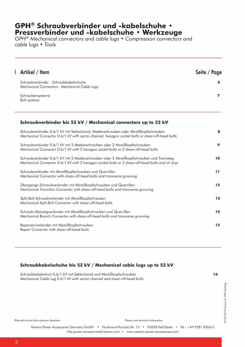
Schraubverbinder - Schraubkabelschuhe 6Mechanical Connectors - Mechanical Cable Lugs
Schraubensysteme 7Bolt systems
Seite / Page
Schraubverbinder bis 52 kV / Mechanical connectors up to 52 kV
Schraubverbinder 0,6/1 kV mit Sektorkanal, Madenschrauben oder Abreißkopfschrauben 8Mechanical Connector 0.6/1 kV with sector channel, hexagon socket bolts or shear-off-head bolts
Schraubverbinder 0,6/1 kV mit 2 Madenschrauben oder 2 Abreißkopfschrauben 9Mechanical Connector 0.6/1 kV with 2 hexagon socket bolts or 2 shear-off-head bolts
Schraubverbinder 0,6/1 kV mit 2 Madenschrauben oder 2 Abreißkopfschrauben und Trennsteg 10Mechanical Connector 0.6/1 kV with 2 hexagon socket bolts or 2 shear-off-head bolts and oil stop
Schraubverbinder mit Abreißkopfschrauben und Querrillen 11 Mechanical Connector with shear-off-head bolts and transverse grooving
Übergangs-Schraubverbinder mit Abreißkopfschrauben und Querrillen 12Mechanical Transition Connector with shear-off-head bolts and transverse grooving
Split-Bolt Schraubverbinder mit Abreißkopfschrauben 13Mechanical Split-Bolt Connector with shear-off-head bolts
Schraub-Abzweigverbinder mit Abreißkopfschrauben und Querrillen 14Mechanical Branch Connector with shear-off-head bolts and transverse grooving
Reparaturverbinder mit Abreißkopfschrauben 15Repair Connector with shear-off-head bolts
Schraubkabelschuhe bis 52 kV / Mechanical cable lugs up to 52 kV
Schraubkabelschuh 0,6/1 kV mit Sektorkanal und Abreißkopfschrauben 16Mechanical Cable Lug 0.6/1 kV with sector channel and shear-off-head bolts
GPH® Schraubverbinder und -kabelschuhe • Pressverbinder und -kabelschuhe • WerkzeugeGPH® Mechanical connectors and cable lugs • Compression connectors and cable lugs • Tools
22-0
2-20
19 V
ersi
on 0
1 G
PH-K
atal
og
3
Bitte technische Informationen beachten. Please note technical information.
Nexans Power Accessories Germany GmbH • Ferdinand-Porsche-Str. 12 • 95028 Hof/Saale • Tel.: +49 9281 [email protected] • www.nexans-power-accessories.com
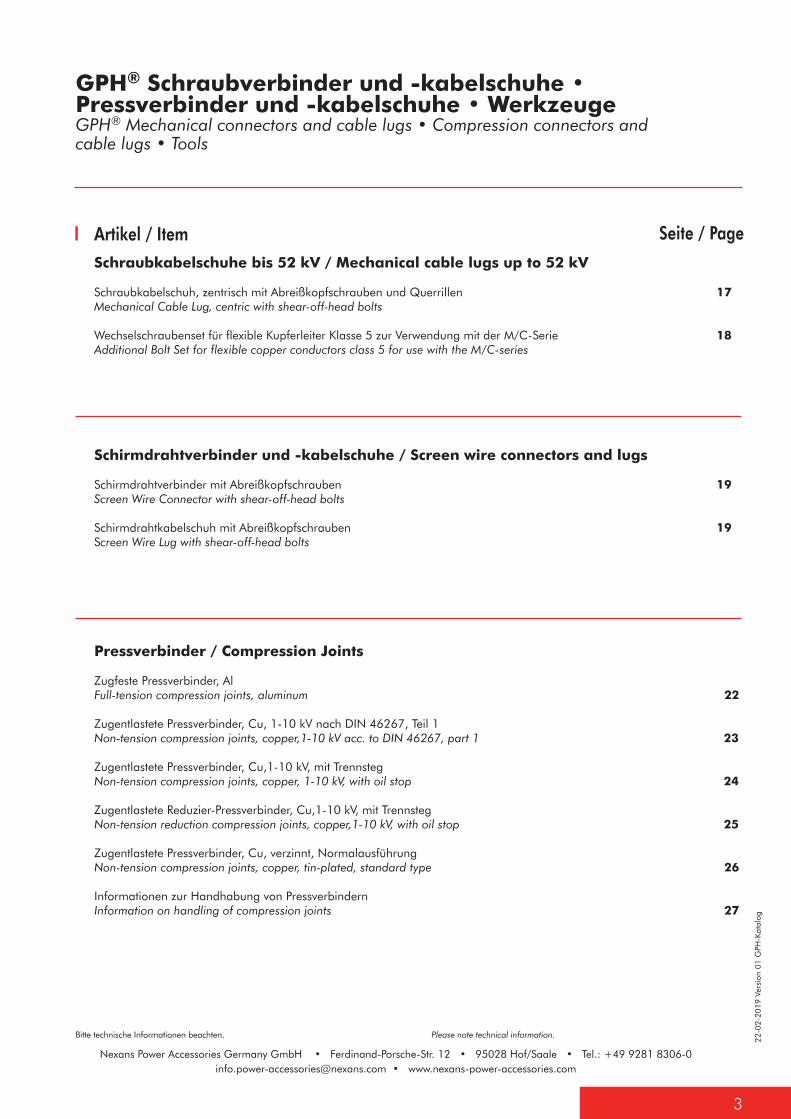
Seite / PageArtikel / ItemSchraubkabelschuhe bis 52 kV / Mechanical cable lugs up to 52 kV
Schraubkabelschuh, zentrisch mit Abreißkopfschrauben und Querrillen 17Mechanical Cable Lug, centric with shear-off-head bolts
Wechselschraubenset für flexible Kupferleiter Klasse 5 zur Verwendung mit der M/C-Serie 18Additional Bolt Set for flexible copper conductors class 5 for use with the M/C-series
Schirmdrahtverbinder und -kabelschuhe / Screen wire connectors and lugs
Schirmdrahtverbinder mit Abreißkopfschrauben 19Screen Wire Connector with shear-off-head bolts
Schirmdrahtkabelschuh mit Abreißkopfschrauben 19Screen Wire Lug with shear-off-head bolts
GPH® Schraubverbinder und -kabelschuhe • Pressverbinder und -kabelschuhe • WerkzeugeGPH® Mechanical connectors and cable lugs • Compression connectors and cable lugs • Tools
Pressverbinder / Compression Joints
Zugfeste Pressverbinder, Al Full-tension compression joints, aluminum 22 Zugentlastete Pressverbinder, Cu, 1-10 kV nach DIN 46267, Teil 1 Non-tension compression joints, copper,1-10 kV acc. to DIN 46267, part 1 23
Zugentlastete Pressverbinder, Cu,1-10 kV, mit Trennsteg Non-tension compression joints, copper, 1-10 kV, with oil stop 24
Zugentlastete Reduzier-Pressverbinder, Cu,1-10 kV, mit Trennsteg Non-tension reduction compression joints, copper,1-10 kV, with oil stop 25
Zugentlastete Pressverbinder, Cu, verzinnt, Normalausführung Non-tension compression joints, copper, tin-plated, standard type 26
Informationen zur Handhabung von Pressverbindern Information on handling of compression joints 27

22-0
2-20
19 V
ersi
on 0
1 G
PH-K
atal
og
Bitte technische Informationen beachten. Please note technical information.
Nexans Power Accessories Germany GmbH • Ferdinand-Porsche-Str. 12 • 95028 Hof/Saale • Tel.: +49 9281 [email protected] • www.nexans-power-accessories.com
4
GPH® Schraubverbinder und -kabelschuhe • Pressverbinder und -kabelschuhe • WerkzeugeGPH® Mechanical connectors and cable lugs • Compression connectors and cable lugs • Tools
Artikel / Item
Presskabelschuhe / Compression Cable Lugs
Presskabelschuhe, Cu, nach DIN 46235 / Compression cable lugs, copper, acc. to DIN 46235 28
Presskabelschuhe, Cu, längsdicht / Compression cable lugs, copper, longitudinally sealed 31
Presskabelschuhe, Cu, Normalausführung / Compression cable lugs, copper, standard type 33
Presskabelschuhe, Al, nach DIN 46329, längsdicht Compression cable lugs, aluminum, longitudinally sealed acc. to DIN 46329 35
Cupal Scheibe, Al/Cu / Cupal Disc, Al/Cu 37
Pressabzweigklemmen, Cu, H-Form / Copper compression tap connectors, H-shape 37
Informationen zur Handhabung von Presskabelschuhen / Information on handling of compression cable lugs 38
Werkzeuge / Tools
Gegenhalter / Holding tool 40 Kabelschneider / Cable cutter 40 Werkzeugkoffer/ Tool set 41 Abisolierzange / Insulation stripping tool 41 Drehmomentverstärker DMV65 mit Werkzeugkoffer 42Torque amplifier DMV65 with tool case
Drehmomentverstärker DMV65, potentialgetrennt, mit Werkzeugkoffer 43Torque amplifier DMV65, isolated, with tool case Drehmomentverstärker iDMV65 mit integriertem Antrieb und Werkzeugkoffer 44Torque amplifier iDMV65, with integrated drive and tool case
ASKO COMPACT Akku-Schlagschrauber mit Werkzeugkoffer 45ASKO COMPACT Impact wrench with tool case
Innensechskant-Einsätze, schlagschraubergeeignet, für 1/2" Werkzeugaufnahme 46
Allen Key 1/2" for impact wrenches
Außensechskant-Einsätze, schlagschraubergeeignet, für 1/2"
Werkzeugaufnahme 46
Socket for 1/2" for impact wrenches
Mechanische Presszange MHP 10/300 Mechanical compression tool MHP 10/300 47
Presswerkzeug-Einsätze für mechanische Presszange MHP 10/300Hexagonal crimping dies for mechanical compression tool MHP 10/300 47
Seite / Page

5
GPH® SCHRAUBVERBINDER /SCHRAUBKABELSCHUHE Mechanical Connectors / Cable Lugs
Nexans Power Accessories Germany GmbH • Ferdinand-Porsche-Str. 12 • 95028 Hof/Saale • Tel.: +49 9281 [email protected] • www.nexans-power-accessories.com
22-0
2-20
19 V
ersi
on 0
1 G
PH-K
atal
og
Bitte technische Informationen beachten. Please note technical information.
Nexans Power Accessories Germany GmbH • Ferdinand-Porsche-Str. 12 • 95028 Hof/Saale • Tel.: +49 9281 [email protected] • www.nexans-power-accessories.com
6
GPH® Schraubverbinder • SchraubkabelschuheGPH® Mechanical Connectors • Mechanical Cable Lugs
Mechanical connectors by GPH® are a reliable and efficient way of connecting different conductor cross sections and conductor materials for 1 kV up to 52 kV. All connectors are available with either hexagon socket bolts or shear-off-head bolts.
Connector Body:- high-strength aluminum alloy- rolled thread
Bolts:- electro tin-plated, aluminum bolts excepted- lubricated with special grease
Advantages of shear-off-head bolts:- easy installation- bolt heads shear-off at the required torque moment- no torque wrench required
Economy:- low stock required because two connector types cover the most common cross sections- no crimping tools required
Electrical test:- tested acc. to VDE 0220, IEC 61238-1- The test was done with manual assembly. In dependence of different conductor material and/or different conductor constructions as well as when using impact wrenches the values may differ from the test results.
Availability:- different sizes available- individual customised problem solutions and special designs on request
Abbreviations of various conductor types:- rm = round stranded- sm = sector stranded - re = round solid- se = sector solid
Do you have further questions? Please, contact us!
GPH® Schraubverbinder sind eine zuverlässige und wirt-schaftliche Art der Verbindung gleicher oder verschieden-artiger Leiterquerschnitte und Leitermaterialien für 1 kV bis 52 kV. Alle Verbinder sind je nach Einsatzbereich mit Madenschrauben oder drehmomentbegrenzten Abreiß-kopfschrauben lieferbar.
Verbinderkörper:- hochfeste Alu-Legierung- Gewinde geformt
Schrauben:- galvanisch verzinnt, Alu-Schrauben ausgenommen- mit Spezialfett versehen
Vorteile der Abreißkopfschraube:- einfache Montage- der Schraubenkopf reißt bei gefordertem Anzugsmoment ab- kein Drehmomentschlüssel erforderlich
Wirtschaftlichkeit:- geringe Lagerhaltung, da je ein Schraubverbinder mehrere Pressverbindertypen ersetzen kann- keine Presswerkzeuge erforderlich
Elektrische Prüfung:- geprüft nach VDE 0220 bzw. IEC 61238-1- Der Prüfaufbau erfolgte mit Handmontage. In Abhängigkeit von unterschiedlichem Leitermaterial bzw. unterschiedlicher Leiterkonstruktion sowie bei der Verwendung von Schlagschraubern können sich Abweichungen von den Prüfwerten ergeben.
Lieferauswahl:- lieferbar in verschiedenen Größen- individuelle Problemlösungen und Sonderanfertigungen auf Anfrage
Abkürzungen der verschiedenen Leitertypen- rm = rund-mehrdrähtig- sm = sektor-mehrdrähtig- re = rund-eindrähtig- se = sektor-eindrähtig
Haben Sie weitere Fragen? Rufen Sie uns an oder schreiben Sie uns!
22-0
2-20
19 V
ersi
on 0
1 G
PH-K
atal
og
7
Bitte technische Informationen beachten. Please note technical information.
Nexans Power Accessories Germany GmbH • Ferdinand-Porsche-Str. 12 • 95028 Hof/Saale • Tel.: +49 9281 [email protected] • www.nexans-power-accessories.com
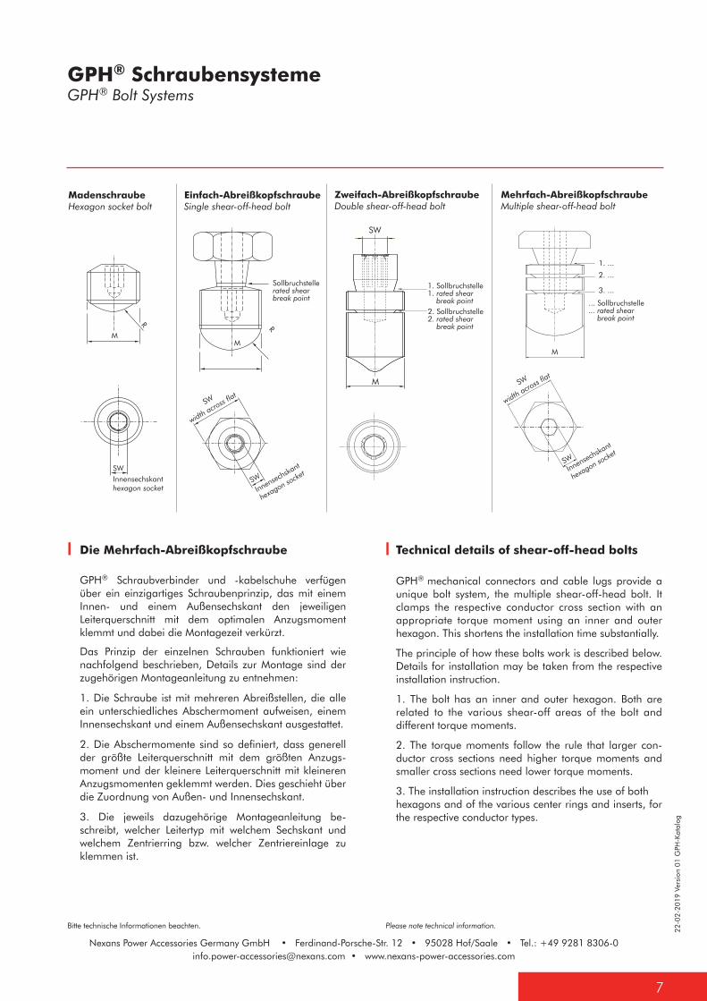
Technical details of shear-off-head bolts
GPH® mechanical connectors and cable lugs provide a unique bolt system, the multiple shear-off-head bolt. It clamps the respective conductor cross section with an appropriate torque moment using an inner and outer hexagon. This shortens the installation time substantially.
The principle of how these bolts work is described below. Details for installation may be taken from the respective installation instruction.
1. The bolt has an inner and outer hexagon. Both are related to the various shear-off areas of the bolt and different torque moments.
2. The torque moments follow the rule that larger con-ductor cross sections need higher torque moments and smaller cross sections need lower torque moments.
3. The installation instruction describes the use of both hexagons and of the various center rings and inserts, for the respective conductor types.
Die Mehrfach-Abreißkopfschraube
GPH® Schraubverbinder und -kabelschuhe verfügen über ein einzigartiges Schraubenprinzip, das mit einem Innen- und einem Außensechskant den jeweiligen Leiterquerschnitt mit dem optimalen Anzugsmoment klemmt und dabei die Montagezeit verkürzt.
Das Prinzip der einzelnen Schrauben funktioniert wie nachfolgend beschrieben, Details zur Montage sind der zugehörigen Montageanleitung zu entnehmen:
1. Die Schraube ist mit mehreren Abreißstellen, die alle ein unterschiedliches Abschermoment aufweisen, einem Innensechskant und einem Außensechskant ausgestattet.
2. Die Abschermomente sind so definiert, dass generell der größte Leiterquerschnitt mit dem größten Anzugs-moment und der kleinere Leiterquerschnitt mit kleineren Anzugsmomenten geklemmt werden. Dies geschieht über die Zuordnung von Außen- und Innensechskant.
3. Die jeweils dazugehörige Montageanleitung be-schreibt, welcher Leitertyp mit welchem Sechskant und welchem Zentrierring bzw. welcher Zentriereinlage zu klemmen ist.
GPH® SchraubensystemeGPH® Bolt Systems
1. Sollbruchstelle1. rated shear break point
Sollbruchstellerated shearbreak point
SWInnensechskanthexagon socket
2. Sollbruchstelle2. rated shear break point
M
SW
SW
width across f
lat
SWInnensechska
nt
hexagon socke
t
MM
R
R
M
SWInnensechska
nt
hexagon socke
t
SW
width across f
lat
... Sollbruchstelle
... rated shear break point
1. ...
2. ...
3. ...
MadenschraubeHexagon socket bolt
Einfach-AbreißkopfschraubeSingle shear-off-head bolt
Zweifach-AbreißkopfschraubeDouble shear-off-head bolt
Mehrfach-AbreißkopfschraubeMultiple shear-off-head bolt

Nexans Power Accessories Germany GmbH • Ferdinand-Porsche-Str. 12 • 95028 Hof/Saale • Tel.: +49 9281 [email protected] • www.nexans-power-accessories.com
22-0
2-20
19 V
ersi
on 0
1 G
PH-K
atal
og
Bitte technische Informationen beachten. Please note technical information.
Nexans Power Accessories Germany GmbH • Ferdinand-Porsche-Str. 12 • 95028 Hof/Saale • Tel.: +49 9281 [email protected] • www.nexans-power-accessories.com
8
GPH® Schraubverbinder 0,6/1 kV mit Sektorkanal,Madenschrauben oder AbreißkopfschraubenGPH® Mechanical Connector 0.6/1 kV with sector channel, hexagon socket bolts or shear-off-head bolts
Listen-Nr.Cat. no.
AL in mm² nach EN 60228
AL in mm² acc. to EN 60228
CU in mm² nach EN 60228CU in mm²
acc. to EN 60228
CU Klasse 5in mm2
nach EN 60228CU class 5 in mm2
acc. to EN 60228
Maße in mm
Dimensions mm
WerkzeugAußen- & Innen-
Sechskant Tool/outer and inner
hexagon
rmroundstrand.
smsector strand.
reround solid
sesector solid
rmroundstrand.
smsector strand.
reround solid
ohne Hülsewithout contact sleeve
mit Hülsewith
contact sleeve
L D d Abscher-schraubeshear-off-head bolt
Maden-schraubehexagon
socket bolt
D1,5-16 SV(-T/-S)-V-K1),3) 10-16 10-16 1,0-16 1,0-16 1,0-16 30 12 6,1 SW8
D1,5-16 SV(-T/-S)-V1),3) 1,0-16 1,0-16 1,0-16 30 12 6,1 SW34)
D1,5-35 SV(-T/-S)-V-K3) 10-35 35 10-35 35 1,5-35 35 1,5-35 1,5-35 36 16 9,0 SW52)
D10-35 SV(-T/-S)-V(-K)3) 10-35 35 10-35 35 10-35 35 10-35 10-35 36 16 9,0 SW8 SW5
D25-50 SV(-T/-S)-V(-K) 25-50 35-50 25-50 35-50 25-50 35-50 25-35 50 25-357) 36 18 10,0 SW8 SW5
D4-50 SV(-T/-S)-V-K 10-50 35-50 10-50 35-50 4-50 35-50 4-35 50 4-357) 36 18 10,0 SW52)
D16-95 SV(-T/-S)-V(-K) 16-95 35-95 16-95 35-95 16-95 35-95 16-35 95 16-707) 55 25 14,0 SW10 SW6
D25-150 SV(-T/-S)-V-K 25-150 35-150 25-150 35-150 25-150 35-150 16-35 120-150 25-957) 70 28 17,0 SW62) 5)
D35-150 SV(-T/-S)-V(-K) 35-150 35-150 50-150 50-150 35-150 35-150 35 120-150 35-957) 70 28 17,0 SW135) SW65)
D25-185 SV(-T/-S)-V-K6) 25-185 35-185 25-185 35-185 25-185 35-185 25-35 150 25-1207) 80 32 19,0 SW62)
D70-185 SV(-T/-S)-V(-K)6) 70-185 70-185 70-185 70-185 70-185 70-185 150-185 70-1207) 80 32 19,0 SW13 SW6
D50-240 SV(-T/-S)-V-K6) 50-240 50-240 50-240 50-240 50-240 50-240 240 50-1857) 120 35 22,0 SW82)
D120-240 SV(-T/-S)-V(-K)6) 120-240 120-240 120-240 120-240 120-240 120-240 240 120-1857) 120 35 22,0 SW13 SW6
D50-300 SV(-T/-S)-V(-K) 6) 50-300 50-300 50-300 50-300 50-240 50-240 240 95-185 128 38 23,0 SW82)
D150-300 SV(-T/-S)-V(-K)6) 150-300 150-300 150-300 150-300 150-240 150-240 240 150-185 128 38 23,0 SW13 SW8
D25-185 SV-T-V-K
D...-S
D...-T
D1,5-16 SV-S-V-K
1) Verbinderkörper: Messing2) Zweifach-Abreißkopfschraube 3) Ohne Sektorkanal4) Madenschraube, Stahl
1) Connector Body: brass2) Double shear-off-head bolt 3) Without sector channel 4) Hexagon socket bolt, steel
Verbinderkörper
Werkstoff: Alu-Legierung Ausführung:
D...-S: mit Sichtloch D...-T: mit Trennsteg
Oberfläche:
D...-V: galvanisch verzinnt
Schrauben
Werkstoff: Alu-Legierung
Oberfläche: blank
Ausführung:
D...: mit Madenschrauben D...-K: mit Abreißkopf- schrauben
Connector Body
Material: high strength aluminum alloy Type:
D...-S: with inspection hole D...-T: with oil stop
Surface:
D...-V: tin-plated
Bolts
Material: high strength aluminum alloy
Surface: uncoated
Type: D...: with hexagon socket bolts D...-K: with shear-off-head bolts
5) Schraube, Messing (verzinnt)6) Mit vier Abreißkopfschrauben7) Kontakthülsen auf Anfrage erhältlich
5) Bolt, brass (tin-plated)6) With four shear-off-head bolts7) Contact sleeves available on request
22-0
2-20
19 V
ersi
on 0
1 G
PH-K
atal
og
9
Bitte technische Informationen beachten. Please note technical information.
Nexans Power Accessories Germany GmbH • Ferdinand-Porsche-Str. 12 • 95028 Hof/Saale • Tel.: +49 9281 [email protected] • www.nexans-power-accessories.com
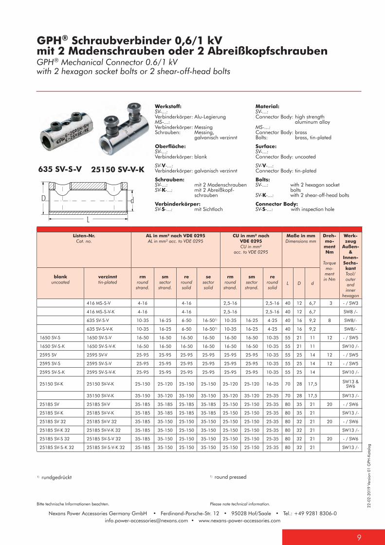
635 SV-S-V 25150 SV-V-K
Material: SV-...: Connector Body: high strength aluminum alloy MS-...: Connector Body: brass Bolts: brass, tin-plated
Surface: SV-...: Connector Body: uncoated
SV-V-...: Connector Body: tin-plated
Bolts: SV-...: with 2 hexagon socket bolts SV-K-...: with 2 shear-off-head bolts
Connector Body: SV-S-...: with inspection hole
Werkstoff: SV-...: Verbinderkörper: Alu-Legierung MS-...: Verbinderkörper: Messing Schrauben: Messing, galvanisch verzinnt
Oberfläche: SV-...: Verbinderkörper: blank
SV-V-...: Verbinderkörper: galvanisch verzinnt
Schrauben: SV-...: mit 2 Madenschrauben SV-K-...: mit 2 Abreißkopf- schrauben
Verbinderkörper: SV-S-...: mit Sichtloch
1) rundgedrückt 1) round pressed
GPH® Schraubverbinder 0,6/1 kV mit 2 Madenschrauben oder 2 AbreißkopfschraubenGPH® Mechanical Connector 0.6/1 kV with 2 hexagon socket bolts or 2 shear-off-head bolts
Listen-Nr.Cat. no.
AL in mm² nach VDE 0295AL in mm² acc. to VDE 0295
CU in mm² nach VDE 0295CU in mm²
acc. to VDE 0295
Maße in mmDimensions mm
Dreh-mo-ment Nm
Torque mo-ment in Nm
Werk-zeug
Außen- &
Innen- Sechs-kant Tool/ outer and inner
hexagon
blankuncoated
verzinnttin-plated
rmroundstrand.
smsector strand.
reround solid
sesector solid
rmroundstrand.
smsector strand.
reround solid
L D d
416 MS-S-V 4-16 4-16 2,5-16 2,5-16 40 12 6,7 3 - / SW3
416 MS-S-V-K 4-16 4-16 2,5-16 2,5-16 40 12 6,7 SW8 /-
635 SV-S-V 10-35 16-25 6-50 16-501) 10-35 16-25 4-25 40 16 9,2 8 SW8/-
635 SV-S-V-K 10-35 16-25 6-50 16-501) 10-35 16-25 4-25 40 16 9,2 SW8/-
1650 SV-S 1650 SV-S-V 16-50 16-50 16-50 16-50 16-50 16-50 10-35 55 21 11 12 - / SW5
1650 SV-S-K 1650 SV-S-V-K 16-50 16-50 16-50 16-50 16-50 16-50 10-35 55 21 11 SW10 /-
2595 SV 2595 SV-V 25-95 25-95 25-95 25-95 25-95 25-95 10-35 55 25 14 12 - / SW5
2595 SV-S 2595 SV-S-V 25-95 25-95 25-95 25-95 25-95 25-95 10-35 55 25 14 12 - / SW5
2595 SV-S-K 2595 SV-S-V-K 25-95 25-95 25-95 25-95 25-95 25-95 10-35 55 25 14 SW10 /-
25150 SV-K 25150 SV-V-K 25-150 25-120 25-150 25-150 25-120 25-120 16-35 70 28 17,5 SW13 &SW6
35150 SV-V-K 35-150 35-120 35-150 35-150 35-120 35-120 25-35 70 28 17,5 SW13 /-
25185 SV 25185 SV-V 35-185 35-185 25-185 35-185 25-150 25-150 25-35 80 35 21 20 - / SW6
25185 SV-K 25185 SV-V-K 35-185 35-185 25-185 35-185 25-150 25-150 25-35 80 35 21 SW13 /-
25185 SV 32 25185 SV-V 32 35-185 35-150 25-150 35-150 25-150 25-150 25-35 80 32 21 20 - / SW6
25185 SV-K 32 25185 SV-V-K 32 35-185 35-150 25-150 35-150 25-150 25-150 25-35 80 32 21 SW13 /-
25185 SV-S 32 25185 SV-S-V 32 35-185 35-150 25-150 35-150 25-150 25-150 25-35 80 32 21 20 - / SW6
25185 SV-S-K 32 25185 SV-S-V-K 32 35-185 35-150 25-150 35-150 25-150 25-150 25-35 80 32 21 SW13 /-
Nexans Power Accessories Germany GmbH • Ferdinand-Porsche-Str. 12 • 95028 Hof/Saale • Tel.: +49 9281 [email protected] • www.nexans-power-accessories.com
22-0
2-20
19 V
ersi
on 0
1 G
PH-K
atal
og
Bitte technische Informationen beachten. Please note technical information.
Nexans Power Accessories Germany GmbH • Ferdinand-Porsche-Str. 12 • 95028 Hof/Saale • Tel.: +49 9281 [email protected] • www.nexans-power-accessories.com
10
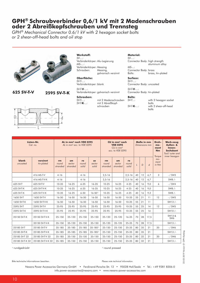
625 SV-T-V 2595 SV-T-K
Material: SV-...: Connector Body: high strength aluminum alloy MS-..: Connector Body: brass Bolts: brass, tin-plated
Surface: SV-T-...: Connector Body: uncoated
SV-T-V-...: Connector Body: tin-plated
Bolts: SV-T...: with 2 hexagon socket bolts SV-T-K-...: with 2 shear-off-head bolts
Werkstoff: SV-...: Verbinderkörper: Alu-Legierung MS-...: Verbinderkörper: Messing Schrauben: Messing, galvanisch verzinnt
Oberfläche: SV-T-...: Verbinderkörper: blank
SV-T-V-...: Verbinderkörper: galvanisch verzinnt
Schrauben: SV-T-...: mit 2 Madenschrauben SV-T-K-...: mit 2 Abreißkopf- schrauben
1) rundgedrückt 1) round pressed
GPH® Schraubverbinder 0,6/1 kV mit 2 Madenschrauben oder 2 Abreißkopfschrauben und TrennstegGPH® Mechanical Connector 0.6/1 kV with 2 hexagon socket bolts or 2 shear-off-head bolts and oil stop
Listen-Nr.Cat. no.
AL in mm² nach VDE 0295AL in mm² acc. to VDE 0295
CU in mm² nach VDE 0295CU in mm²
acc. to VDE 0295
Maße in mmDimensions mm
Dreh-mo-ment Nm
Torque mo-ment in Nm
Werk-zeugAußen- &
Innen- Sechskant
Tool/ outer and inner hexagon
blankuncoated
verzinnttin-plated
rmround
stranded
smsector
stranded
reround solid
sesector solid
rmround
stranded
smsector
stranded
reround solid
L D d
416 MS-T-V 4-16 4-16 2,5-16 2,5-16 40 12 6,7 3 - / SW3
416 MS-T-V-K 4-16 4-16 2,5-16 2,5-16 40 12 6,7 SW8 /-
625 SV-T 625 SV-T-V 10-35 16-25 6-35 16-35 10-25 16-25 4-25 40 16 9,0 6 - / SW4
625 SV-T-K 625 SV-T-V-K 10-35 16-25 6-35 16-35 10-25 16-25 4-25 40 16 9,0 SW8 /-
635 SV-T-K 635 SV-T-V-K 10-35 16-25 6-50 16-501) 10-35 16-25 4-25 40 16 9,2 SW8 /-
1650 SV-T 1650 SV-T-V 16-50 16-50 16-50 16-50 16-50 16-50 10-35 55 21 11 12 - / SW5
1650 SV-T-K 1650 SV-T-V-K 16-50 16-50 16-50 16-50 16-50 16-50 10-35 55 21 11 SW13 /-
2595 SV-T 2595 SV-T-V 25-95 25-95 25-95 25-95 25-95 25-95 10-35 55 25 14 12 - / SW5
2595 SV-T-K 2595 SV-T-V-K 25-95 25-95 25-95 25-95 25-95 25-95 10-35 55 25 14 SW10 /-
25150 SV-T-K 25150 SV-T-V-K 25-150 25-120 25-150 25-150 25-120 25-120 16-35 70 28 17,5 SW13 &SW6
35150 SV-T-V-K 35-150 35-120 35-150 35-150 35-120 35-120 25-35 70 28 17,5 SW13 /-
25185 SV-T 25185 SV-T-V 35-185 35-185 25-185 35-1851) 25-150 25-150 25-35 80 35 21 20 - / SW6
25185 SV-T-K 25185 SV-T-V-K 35-185 35-185 25-185 35-1851) 25-150 25-150 25-35 80 35 21 SW13 /-
25185 SV-T 32 25185 SV-T-V 32 35-185 35-150 25-150 35-150 25-150 25-150 25-35 80 32 21 20 - / SW6
25185 SV-T-K 32 25185 SV-T-V-K 32 35-185 35-150 25-150 35-150 25-150 25-150 25-35 80 32 21 SW13 /-
22-0
2-20
19 V
ersi
on 0
1 G
PH-K
atal
og
11
Bitte technische Informationen beachten. Please note technical information.
Nexans Power Accessories Germany GmbH • Ferdinand-Porsche-Str. 12 • 95028 Hof/Saale • Tel.: +49 9281 [email protected] • www.nexans-power-accessories.com
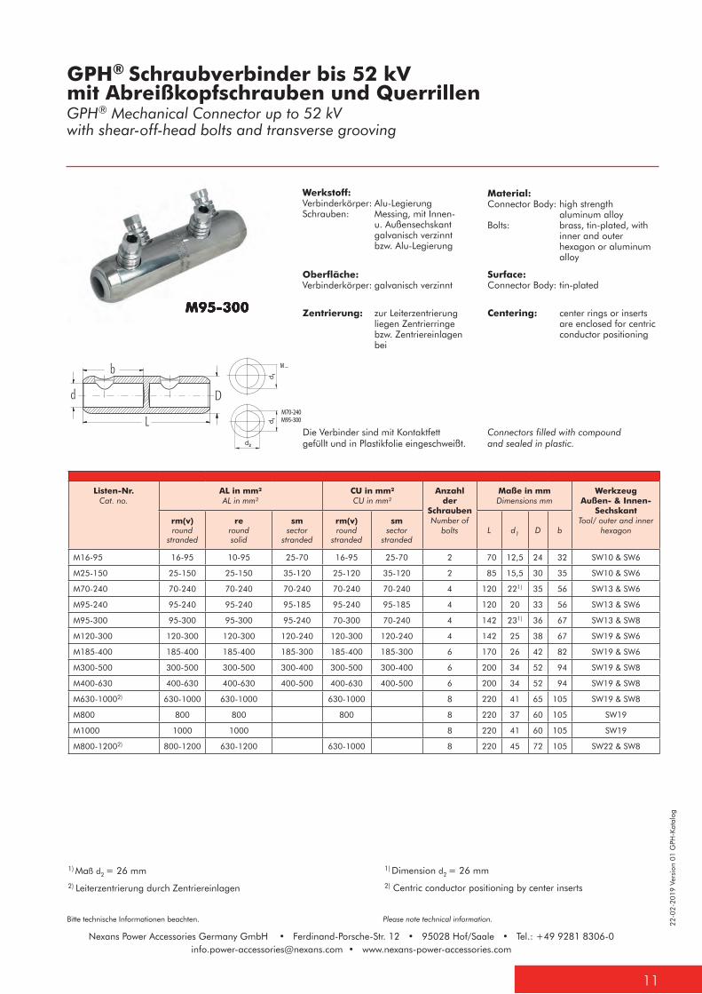
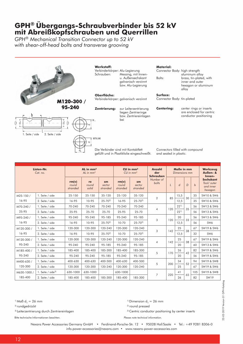
Material:Connector Body: high strength aluminum alloyBolts: brass, tin-plated, with inner and outer hexagon or aluminum alloy
Surface:Connector Body: tin-plated
Centering: center rings or inserts are enclosed for centric conductor positioning
Werkstoff:Verbinderkörper: Alu-LegierungSchrauben: Messing, mit Innen- u. Außensechskant galvanisch verzinnt bzw. Alu-Legierung
Oberfläche:Verbinderkörper: galvanisch verzinnt
Zentrierung: zur Leiterzentrierung liegen Zentrierringe bzw. Zentriereinlagen bei
1) Maß d2 = 26 mm
2) Leiterzentrierung durch Zentriereinlagen
1) Dimension d2 = 26 mm
2) Centric conductor positioning by center inserts
GPH® Schraubverbinder bis 52 kV mit Abreißkopfschrauben und QuerrillenGPH® Mechanical Connector up to 52 kV with shear-off-head bolts and transverse grooving
M95-300
Listen-Nr.Cat. no.
AL in mm²AL in mm²
CU in mm² CU in mm²
Anzahl der
SchraubenNumber of
bolts
Maße in mmDimensions mm
WerkzeugAußen- & Innen-
Sechskant Tool/ outer and inner
hexagon rm(v)round
stranded
reround solid
smsector
stranded
rm(v)round
stranded
smsector
strandedL d1 D b
M16-95 16-95 10-95 25-70 16-95 25-70 2 70 12,5 24 32 SW10 & SW6
M25-150 25-150 25-150 35-120 25-120 35-120 2 85 15,5 30 35 SW10 & SW6
M70-240 70-240 70-240 70-240 70-240 70-240 4 120 221) 35 56 SW13 & SW6
M95-240 95-240 95-240 95-185 95-240 95-185 4 120 20 33 56 SW13 & SW6
M95-300 95-300 95-300 95-240 70-300 70-240 4 142 231) 36 67 SW13 & SW8
M120-300 120-300 120-300 120-240 120-300 120-240 4 142 25 38 67 SW19 & SW6
M185-400 185-400 185-400 185-300 185-400 185-300 6 170 26 42 82 SW19 & SW6
M300-500 300-500 300-500 300-400 300-500 300-400 6 200 34 52 94 SW19 & SW8
M400-630 400-630 400-630 400-500 400-630 400-500 6 200 34 52 94 SW19 & SW8
M630-10002) 630-1000 630-1000 630-1000 8 220 41 65 105 SW19 & SW8
M800 800 800 800 8 220 37 60 105 SW19
M1000 1000 1000 8 220 41 60 105 SW19
M800-12002) 800-1200 630-1200 630-1000 8 220 45 72 105 SW22 & SW8
M95-300
M ...
M70-240M95-300
Connectors filled with compound and sealed in plastic.
Die Verbinder sind mit Kontaktfett gefüllt und in Plastikfolie eingeschweißt.
Nexans Power Accessories Germany GmbH • Ferdinand-Porsche-Str. 12 • 95028 Hof/Saale • Tel.: +49 9281 [email protected] • www.nexans-power-accessories.com
22-0
2-20
19 V
ersi
on 0
1 G
PH-K
atal
og
Bitte technische Informationen beachten. Please note technical information.
Nexans Power Accessories Germany GmbH • Ferdinand-Porsche-Str. 12 • 95028 Hof/Saale • Tel.: +49 9281 [email protected] • www.nexans-power-accessories.com
12
M ...
M70-240
M ...
M70-240
Material:Connector Body: high strength aluminum alloyBolts: brass, tin-plated, with inner and outer hexagon or aluminum alloy
Surface:Connector Body: tin-plated
Centering: center rings or inserts are enclosed for centric conductor positioning
Werkstoff:Verbinderkörper: Alu-LegierungSchrauben: Messing, mit Innen- u. Außensechskant galvanisch verzinnt bzw. Alu-Legierung
Oberfläche:Verbinderkörper: galvanisch verzinnt
Zentrierung: zur Leiterzentrierung liegen Zentrieringe bzw. Zentriereinlagen bei
2) rundgedrückt3) Leiterzentrierung durch Zentriereinlagen
2) round pressed3) Centric conductor positioning by center inserts
GPH® Übergangs-Schraubverbinder bis 52 kV mit Abreißkopfschrauben und QuerrillenGPH® Mechanical Transition Connector up to 52 kV with shear-off-head bolts and transverse grooving
M120-300 / 95-240
1. Seite / side 2. Seite / side
1) Maß d1 = 26 mm 1) Dimension d1 = 26 mm
Listen-Nr.Cat. no.
AL in mm²AL in mm²
CU in mm² CU in mm²
Anzahl der
SchraubenNumber of
bolts
Maße in mmDimensions mm
WerkzeugAußen- &
Innen- Sechskant Tool/ outer and inner hexagon
rm(v)round
stranded
reround solid
smsector
stranded
rm(v)round
stranded
smsector
strandedL d D b
M25-150 /
16-95
1. Seite / side 25-150 25-150 35-120 25-120 35-1202 85
15,530
35 SW10 & SW6
2. Seite / side 16-95 10-95 25-702) 16-95 25-702) 12,5 35 SW10 & SW6
M70-240 /
25-95
1. Seite / side 70-240 70-240 70-240 70-240 70-2404 120
221)
3556 SW13 & SW6
2. Seite / side 25-95 25-70 25-70 25-95 25-70 221) 56 SW13 & SW6
M95-240 /
16-95
1. Seite / side 95-240 95-240 95-185 95-240 95-1853 120
2033
56 SW13 & SW6
2. Seite / side 16-95 10-95 25-702) 10-70 25-702) 12,5 56 SW6
M120-300 /
16-95
1. Seite / side 120-300 120-300 120-240 120-300 120-2403 142
2538
67 SW19 & SW6
2. Seite / side 16-95 10-95 25-702) 10-70 25-702) 12,5 32 SW6
M120-300 /
95-240
1. Seite / side 120-300 120-300 120-240 120-300 120-2404 142
2538
67 SW19 & SW6
2. Seite / side 95-240 95-240 95-185 95-240 95-185 20 60 SW13 & SW6
M185-400 /
95-240
1. Seite / side 185-400 185-400 185-300 185-400 185-3005 170
2642
82 SW19 & SW6
2. Seite / side 95-240 95-240 95-185 95-240 95-185 20 56 SW19 & SW6
M400-630 /
120-300
1. Seite / side 400-630 400-630 400-500 400-630 400-5005 200
3452
94 SW19 & SW8
2. Seite / side 120-300 120-300 120-240 120-300 120-240 25 67 SW19 & SW6
M630-1000 /
185-400
1. Seite / side3) 630-1000 630-1000 630-10007 220
4165
105 SW19 & SW8
2. Seite / side 185-400 185-400 185-300 185-400 185-300 26 82 SW19
M120-300 / 95-240
Connectors filled with compound and sealed in plastic.
Die Verbinder sind mit Kontaktfett gefüllt und in Plastikfolie eingeschweißt.
1
22-0
2-20
19 V
ersi
on 0
1 G
PH-K
atal
og
13
Bitte technische Informationen beachten. Please note technical information.
Nexans Power Accessories Germany GmbH • Ferdinand-Porsche-Str. 12 • 95028 Hof/Saale • Tel.: +49 9281 [email protected] • www.nexans-power-accessories.com
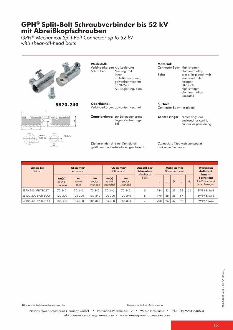
Material: Connector Body: high strength aluminum alloy Bolts: brass, tin-plated, with inner and outer hexagon SB70-240: high strength aluminum alloy, uncoated
Werkstoff: Verbinderkörper: Alu-Legierung Schrauben: Messing, mit Innen- u. Außensechskant, galvanisch verzinnt SB70-240: Alu-Legierung, blank
Oberfläche: Verbinderkörper: galvanisch verzinnt
Zentrierringe: zur Leiterzentrierung liegen Zentrierringe bei
SB120-300SB185-400
SB70-240
L
SB120-300SB185-400
SB70-240
L
SB70-240
GPH® Split-Bolt Schraubverbinder bis 52 kVmit AbreißkopfschraubenGPH® Mechanical Split-Bolt Connector up to 52 kVwith shear-off-head bolts
Listen-Nr.Cat. no.
AL in mm² AL in mm²
CU in mm² CU in mm²
Anzahl der SchraubenNumber of
bolts
Maße in mmDimensions mm
WerkzeugAußen- &
Innen- Sechskant
Tool/ outer and inner hexagon
rm(v)round
stranded
reround solid
smsector
stranded
rm(v)round
stranded
smsector
strandedL d1 D b d2
SB70-240 SPLIT-BOLT 70-240 70-240 70-240 70-240 70-240 5 144 22 35 56 26 SW13 & SW6
SB120-300 SPLIT-BOLT 120-300 120-300 120-240 120-300 120-240 5 170 25 38 67 SW19 & SW6
SB185-400 SPLIT-BOLT 185-400 185-400 185-300 185-400 185-300 7 200 26 42 82 SW19 & SW6
Surface: Connector Body: tin-plated
Center rings: center rings are enclosed for centric conductor positioning
Connectors filled with compound and sealed in plastic.
Die Verbinder sind mit Kontaktfett gefüllt und in Plastikfolie eingeschweißt.
Nexans Power Accessories Germany GmbH • Ferdinand-Porsche-Str. 12 • 95028 Hof/Saale • Tel.: +49 9281 [email protected] • www.nexans-power-accessories.com
22-0
2-20
19 V
ersi
on 0
1 G
PH-K
atal
og
Bitte technische Informationen beachten. Please note technical information.
Nexans Power Accessories Germany GmbH • Ferdinand-Porsche-Str. 12 • 95028 Hof/Saale • Tel.: +49 9281 [email protected] • www.nexans-power-accessories.com
14
L b2
b1 d1d2
D
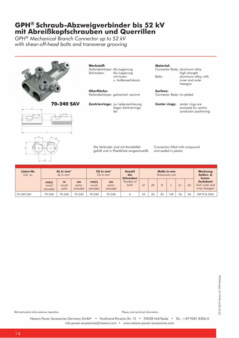
Material:Connector Body: aluminum alloy high strengthBolts: aluminum alloy, with inner and outer hexagon Surface:Connector Body: tin-plated
Center rings: center rings are enclosed for centric conductor positioning
Werkstoff:Verbinderkörper: Alu-LegierungSchrauben: Alu-Legierung mit Innen- u. Außensechskant,
Oberfläche:Verbinderkörper: galvanisch verzinnt
Zentrierringe: zur Leiterzentrierung liegen Zentrierringe bei
70-240 SAV
GPH® Schraub-Abzweigverbinder bis 52 kV mit Abreißkopfschrauben und QuerrillenGPH® Mechanical Branch Connector up to 52 kVwith shear-off-head bolts and transverse grooving
Listen-Nr.Cat. no.
AL in mm² AL in mm²
CU in mm² CU in mm²
Anzahl der
SchraubenNumber of
bolts
Maße in mmDimensions mm
WerkzeugAußen- &
Innen- Sechskant
Tool/ outer and inner hexagon
rm(v)round
stranded
reround solid
smsector
stranded
rm(v)round
stranded
smsector
strandedd1 d2 D L b1 b2
70-240 SAV 70-240 70-240 70-240 70-240 70-240 6 22 26 35 140 56 34 SW19 & SW6
L b2
b1 d1d2
D
70-240 SAV
Connectors filled with compound and sealed in plastic.
Die Verbinder sind mit Kontaktfett gefüllt und in Plastikfolie eingeschweißt.
22-0
2-20
19 V
ersi
on 0
1 G
PH-K
atal
og
15
Bitte technische Informationen beachten. Please note technical information.
Nexans Power Accessories Germany GmbH • Ferdinand-Porsche-Str. 12 • 95028 Hof/Saale • Tel.: +49 9281 [email protected] • www.nexans-power-accessories.com
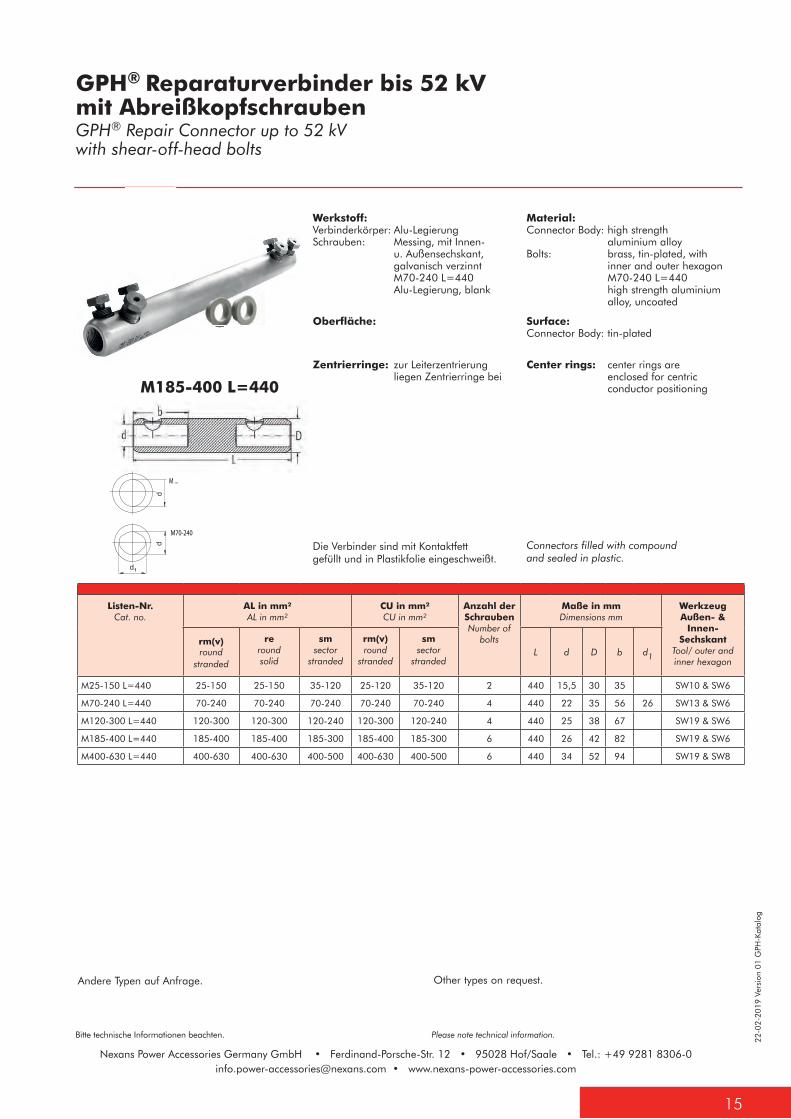
Werkstoff:Verbinderkörper: Alu-LegierungSchrauben: Messing, mit Innen- u. Außensechskant, galvanisch verzinnt M70-240 L=440 Alu-Legierung, blank
Oberfläche:Verbinderkörper: galvanisch verzinnt
Zentrierringe: zur Leiterzentrierung liegen Zentrierringe bei
Die Verbinder sind mit Kontaktfett gefüllt und in Plastikfolie eingeschweißt.
Andere Typen auf Anfrage. Other types on request.
M185-400 L=440
GPH® Reparaturverbinder bis 52 kVmit AbreißkopfschraubenGPH® Repair Connector up to 52 kVwith shear-off-head bolts
Material:Connector Body: high strength aluminium alloyBolts: brass, tin-plated, with inner and outer hexagon M70-240 L=440 high strength aluminium alloy, uncoated
Surface:Connector Body: tin-plated
Center rings: center rings are enclosed for centric conductor positioning
Connectors filled with compound and sealed in plastic.
Listen-Nr.Cat. no.
AL in mm² AL in mm²
CU in mm² CU in mm²
Anzahl der SchraubenNumber of
bolts
Maße in mmDimensions mm
WerkzeugAußen- &
Innen- Sechskant
Tool/ outer and inner hexagon
rm(v)round
stranded
reround solid
smsector
stranded
rm(v)round
stranded
smsector
strandedL d D b d1
M25-150 L=440 25-150 25-150 35-120 25-120 35-120 2 440 15,5 30 35 SW10 & SW6
M70-240 L=440 70-240 70-240 70-240 70-240 70-240 4 440 22 35 56 26 SW13 & SW6
M120-300 L=440 120-300 120-300 120-240 120-300 120-240 4 440 25 38 67 SW19 & SW6
M185-400 L=440 185-400 185-400 185-300 185-400 185-300 6 440 26 42 82 SW19 & SW6
M400-630 L=440 400-630 400-630 400-500 400-630 400-500 6 440 34 52 94 SW19 & SW8
M ...
M70-240
Nexans Power Accessories Germany GmbH • Ferdinand-Porsche-Str. 12 • 95028 Hof/Saale • Tel.: +49 9281 [email protected] • www.nexans-power-accessories.com
22-0
2-20
19 V
ersi
on 0
1 G
PH-K
atal
og
Bitte technische Informationen beachten. Please note technical information.
Nexans Power Accessories Germany GmbH • Ferdinand-Porsche-Str. 12 • 95028 Hof/Saale • Tel.: +49 9281 [email protected] • www.nexans-power-accessories.com
16
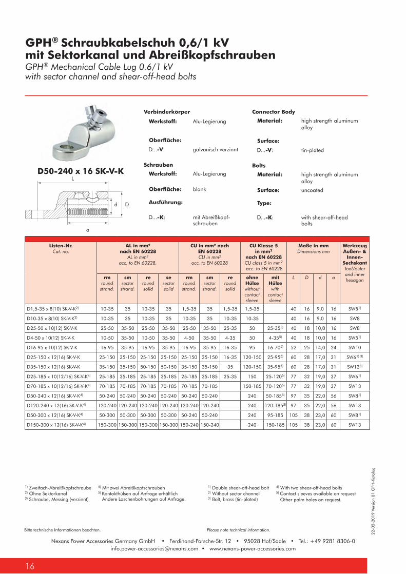
GPH® Schraubkabelschuh 0,6/1 kV mit Sektorkanal und Abreißkopfschrauben GPH® Mechanical Cable Lug 0.6/1 kV with sector channel and shear-off-head bolts
Listen-Nr.Cat. no.
AL in mm²nach EN 60228
AL in mm² acc. to EN 60228,
CU in mm² nach EN 60228CU in mm²
acc. to EN 60228
CU Klasse 5 in mm2
nach EN 60228CU class 5 in mm2
acc. to EN 60228
Maße in mmDimensions mm
WerkzeugAußen- &
Innen- Sechskant Tool/outer and inner hexagonrm
roundstrand.
smsector strand.
reround solid
sesector solid
rmroundstrand.
smsector strand.
reround solid
ohne Hülsewithout contact sleeve
mit Hülsewith
contact sleeve
L D d a
D1,5-35 x 8(10) SK-V-K2) 10-35 35 10-35 35 1,5-35 35 1,5-35 1,5-35 40 16 9,0 16 SW51)
D10-35 x 8(10) SK-V-K2) 10-35 35 10-35 35 10-35 35 10-35 10-35 40 16 9,0 16 SW8
D25-50 x 10(12) SK-V-K 25-50 35-50 25-50 35-50 25-50 35-50 25-35 50 25-355) 40 18 10,0 16 SW8
D4-50 x 10(12) SK-V-K 10-50 35-50 10-50 35-50 4-50 35-50 4-35 50 4-355) 40 18 10,0 16 SW51)
D16-95 x 10(12) SK-V-K 16-95 35-95 16-95 35-95 16-95 35-95 16-35 95 16-705) 52 25 14,0 24 SW10
D25-150 x 12(16) SK-V-K 25-150 35-150 25-150 35-150 25-150 35-150 16-35 120-150 25-955) 60 28 17,0 31 SW61) 3)
D35-150 x 12(16) SK-V-K 35-150 35-150 50-150 50-150 35-150 35-150 35 120-150 35-955) 60 28 17,0 31 SW133)
D25-185 x 10(12/16) SK-V-K4) 25-185 35-185 25-185 35-185 25-185 35-185 25-35 150 25-1205) 77 32 19,0 37 SW61)
D70-185 x 10(12/16) SK-V-K4) 70-185 70-185 70-185 70-185 70-185 70-185 150-185 70-1205) 77 32 19,0 37 SW13
D50-240 x 12(16) SK-V-K4) 50-240 50-240 50-240 50-240 50-240 50-240 240 50-1855) 97 35 22,0 56 SW81)
D120-240 x 12(16) SK-V-K4) 120-240 120-240 120-240 120-240 120-240 120-240 240 120-1855) 97 35 22,0 56 SW13
D50-300 x 12(16) SK-V-K4) 50-300 50-300 50-300 50-300 50-240 50-240 240 95-185 105 38 23,0 60 SW81)
D150-300 x 12(16) SK-V-K4) 150-300 150-300 150-300 150-300 150-240 150-240 240 150-185 105 38 23,0 60 SW13
D50-240 x 16 SK-V-K
1) Zweifach-Abreißkopfschraube 4) Mit zwei Abreißkopfschrauben2) Ohne Sektorkanal 5) Kontakthülsen auf Anfrage erhältlich3) Schraube, Messing (verzinnt)
1) Double shear-off-head bolt 4) With two shear-off-head bolts2) Without sector channel 5) Contact sleeves available on request3) Bolt, brass (tin-plated)
Verbinderkörper
Werkstoff: Alu-Legierung
Oberfläche:
D...-V: galvanisch verzinnt
Schrauben
Werkstoff: Alu-Legierung
Oberfläche: blank
Ausführung: D...-K: mit Abreißkopf- schrauben
Connector Body
Material: high strength aluminum alloy Surface:
D...-V: tin-plated
Bolts
Material: high strength aluminum alloy
Surface: uncoated
Type: D...-K: with shear-off-head bolts
Andere Laschenbohrungen auf Anfrage. Other palm holes on request.
a
L
Dd
22-0
2-20
19 V
ersi
on 0
1 G
PH-K
atal
og
17
Bitte technische Informationen beachten. Please note technical information.
Nexans Power Accessories Germany GmbH • Ferdinand-Porsche-Str. 12 • 95028 Hof/Saale • Tel.: +49 9281 [email protected] • www.nexans-power-accessories.com
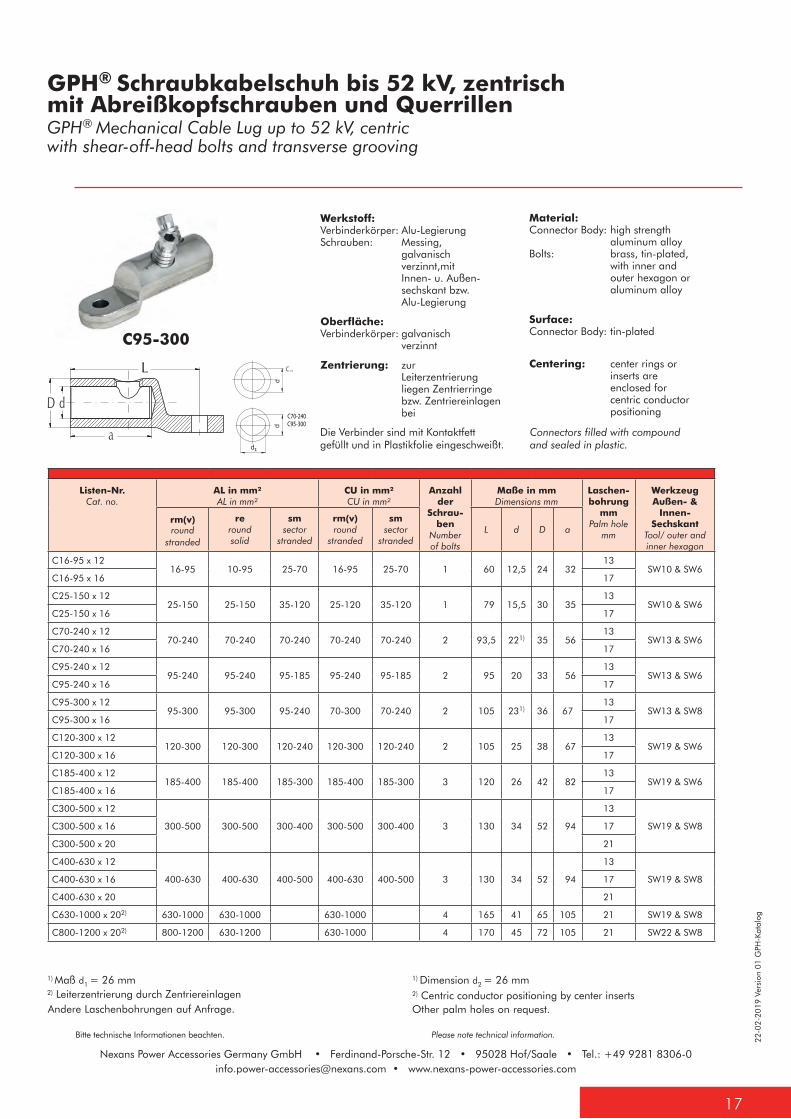
GPH® Schraubkabelschuh bis 52 kV, zentrischmit Abreißkopfschrauben und QuerrillenGPH® Mechanical Cable Lug up to 52 kV, centricwith shear-off-head bolts and transverse grooving
Material:Connector Body: high strength aluminum alloyBolts: brass, tin-plated, with inner and outer hexagon or aluminum alloy
Surface:Connector Body: tin-plated
Centering: center rings or inserts are enclosed for centric conductor positioning
Werkstoff:Verbinderkörper: Alu-LegierungSchrauben: Messing, galvanisch verzinnt,mit Innen- u. Außen- sechskant bzw. Alu-Legierung
Oberfläche:Verbinderkörper: galvanisch verzinnt
Zentrierung: zur Leiterzentrierung liegen Zentrierringe bzw. Zentriereinlagen bei
C95-300
C ...
C70-240C95-300
1) Maß d1 = 26 mm2) Leiterzentrierung durch Zentriereinlagen
1) Dimension d2 = 26 mm2) Centric conductor positioning by center inserts
Andere Laschenbohrungen auf Anfrage. Other palm holes on request.
Listen-Nr.Cat. no.
AL in mm² AL in mm²
CU in mm² CU in mm²
Anzahl der
Schrau-ben
Number of bolts
Maße in mmDimensions mm
Laschen-bohrung
mmPalm hole
mm
WerkzeugAußen- &
Innen- Sechskant
Tool/ outer and inner hexagon
rm(v)round
stranded
reround solid
smsector
stranded
rm(v)round
stranded
smsector
strandedL d D a
C16-95 x 1216-95 10-95 25-70 16-95 25-70 1 60 12,5 24 32
13SW10 & SW6
C16-95 x 16 17
C25-150 x 1225-150 25-150 35-120 25-120 35-120 1 79 15,5 30 35
13SW10 & SW6
C25-150 x 16 17
C70-240 x 1270-240 70-240 70-240 70-240 70-240 2 93,5 221) 35 56
13SW13 & SW6
C70-240 x 16 17
C95-240 x 1295-240 95-240 95-185 95-240 95-185 2 95 20 33 56
13SW13 & SW6
C95-240 x 16 17
C95-300 x 1295-300 95-300 95-240 70-300 70-240 2 105 231) 36 67
13SW13 & SW8
C95-300 x 16 17
C120-300 x 12120-300 120-300 120-240 120-300 120-240 2 105 25 38 67
13SW19 & SW6
C120-300 x 16 17
C185-400 x 12185-400 185-400 185-300 185-400 185-300 3 120 26 42 82
13SW19 & SW6
C185-400 x 16 17
C300-500 x 12
300-500 300-500 300-400 300-500 300-400 3 130 34 52 94
13
SW19 & SW8C300-500 x 16 17
C300-500 x 20 21
C400-630 x 12
400-630 400-630 400-500 400-630 400-500 3 130 34 52 94
13
SW19 & SW8C400-630 x 16 17
C400-630 x 20 21
C630-1000 x 202) 630-1000 630-1000 630-1000 4 165 41 65 105 21 SW19 & SW8
C800-1200 x 202) 800-1200 630-1200 630-1000 4 170 45 72 105 21 SW22 & SW8
Connectors filled with compound and sealed in plastic.
Die Verbinder sind mit Kontaktfett gefüllt und in Plastikfolie eingeschweißt.1
Nexans Power Accessories Germany GmbH • Ferdinand-Porsche-Str. 12 • 95028 Hof/Saale • Tel.: +49 9281 [email protected] • www.nexans-power-accessories.com
22-0
2-20
19 V
ersi
on 0
1 G
PH-K
atal
og
Bitte technische Informationen beachten. Please note technical information.
Nexans Power Accessories Germany GmbH • Ferdinand-Porsche-Str. 12 • 95028 Hof/Saale • Tel.: +49 9281 [email protected] • www.nexans-power-accessories.com
18
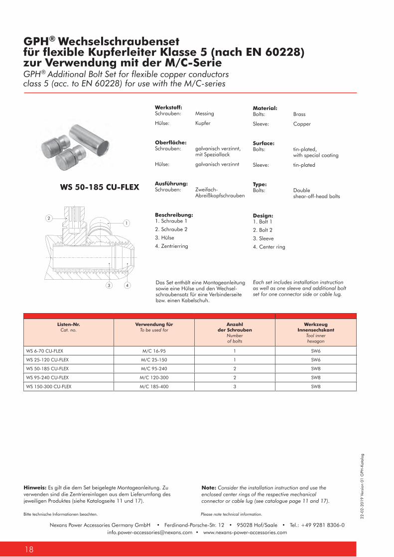
Material:Bolts: Brass
Sleeve: Copper
Surface:Bolts: tin-plated, with special coating
Sleeve: tin-plated
Type: Bolts: Double shear-off-head bolts
Design: 1. Bolt 1
2. Bolt 2
3. Sleeve
4. Center ring
Werkstoff:Schrauben: Messing
Hülse: Kupfer
Oberfläche:Schrauben: galvanisch verzinnt, mit Speziallack
Hülse: galvanisch verzinnt
Ausführung: Schrauben: Zweifach- Abreißkopfschrauben
Beschreibung: 1. Schraube 1
2. Schraube 2
3. Hülse
4. Zentrierring
GPH® Wechselschraubenset für flexible Kupferleiter Klasse 5 (nach EN 60228)zur Verwendung mit der M/C-SerieGPH® Additional Bolt Set for flexible copper conductors class 5 (acc. to EN 60228) for use with the M/C-series
Listen-Nr.Cat. no.
Verwendung fürTo be used for
Anzahl der Schrauben
Number of bolts
Werkzeug Innensechskant
Tool inner hexagon
WS 6-70 CU-FLEX M/C 16-95 1 SW6
WS 25-120 CU-FLEX M/C 25-150 1 SW6
WS 50-185 CU-FLEX M/C 95-240 2 SW8
WS 95-240 CU-FLEX M/C 120-300 2 SW8
WS 150-300 CU-FLEX M/C 185-400 3 SW8
WS 50-185 CU-FLEX
Das Set enthält eine Montageanleitung sowie eine Hülse und den Wechsel-schraubensatz für eine Verbinderseite bzw. einen Kabelschuh.
Each set includes installation instruction as well as one sleeve and additional bolt set for one connector side or cable lug.
Hinweis: Es gilt die dem Set beigelegte Montageanleitung. Zu verwenden sind die Zentriereinlagen aus dem Lieferumfang des jeweiligen Produktes (siehe Katalogseite 11 und 17).
Note: Consider the installation instruction and use the enclosed center rings of the respective mechanical connector or cable lug (see catalogue page 11 and 17).
1
3 4
2

22-0
2-20
19 V
ersi
on 0
1 G
PH-K
atal
og
19
Bitte technische Informationen beachten. Please note technical information.
Nexans Power Accessories Germany GmbH • Ferdinand-Porsche-Str. 12 • 95028 Hof/Saale • Tel.: +49 9281 [email protected] • www.nexans-power-accessories.com
GPH® Schirmdrahtverbinder / -kabelschuhmit AbreißkopfschraubenGPH® Screen Wire Connector / Lugwith shear-off-head bolts
1070 MS-RD 1070/1 x ... MS
Material:Connector Body: brass
Bolts: brass, tin-plated AF 10
Surface:Connector body: tin-plated
Werkstoff:Verbinderkörper: Messing
Schrauben: Messing, galvanisch verzinnt, SW 10
Oberfläche:Verbinderkörper: galvanisch verzinnt
Listen-Nr.Cat. no.
CU in mm²CU in mm²
Flachdraht ALFlat wire AL
Maße in mmDimensions mm
Laschen-bohrung
mm Palm hole
mmAnzahlQuantity
MaßDimension
L D b d a
Schirmdrahtverbinder / Screen Wire Connector
1070 MS-RD 10-50 3-13 1 mm x 5,2 mm 40 16,5 10,2
Schirmdrahtkabelschuh / Screen Wire Lug
1070/1 x 10 MS 10-50 3-13 1 mm x 5,2 mm 39 16 16 10,5 20 10,5
1070/1 x 12 MS 10-50 3-13 1 mm x 5,2 mm 41 16 19 10,5 20 13
Listen-Nr.Cat. no.
CU in mm²CU in mm²
Flachdraht ALFlat wire AL
Maße in mmDimensions mm
Laschen-bohrung
mm Palm hole
mmAnzahlQuantity
MaßDimension
L D b d a
SWL 10-50 x 10 10-50 3-13 1 mm x 4,8 mm 40 18 24 10 16 10,5
SWL 10-50 x 12 10-50 3-13 1 mm x 4,8 mm 40 18 24 10 16 13
SWL 16-95 x 12 16-95 52 25 25 14 24 13
Werkstoff: Verbinderkörper: Alu-Legierung
Schrauben: Alu-Legierung, blank
Oberfläche:Verbinderkörper: galvanisch verzinnt
Material: Connector Body: high strength
aluminum alloy
Bolts: high strength aluminum alloy, uncoatedSurface:Connector body: tin-plated
SWL 10-50 x 10
b
SWL 10-50 x 10
a
L
Dd
D
Ø d
a
b
l
D
Ø d
a
b
l
Ø D
l
Ø d
16,5

20
21
GPH® PRESSVERBINDER / PRESSKABELSCHUHECompression Joints / Compression Cable Lugs
Nexans Power Accessories Germany GmbH • Ferdinand-Porsche-Str. 12 • 95028 Hof/Saale • Tel.: +49 9281 [email protected] • www.nexans-power-accessories.com
22-0
2-20
19 V
ersi
on 0
1 G
PH-K
atal
og
Bitte technische Informationen beachten. Please note technical information.
Nexans Power Accessories Germany GmbH • Ferdinand-Porsche-Str. 12 • 95028 Hof/Saale • Tel.: +49 9281 [email protected] • www.nexans-power-accessories.com
22
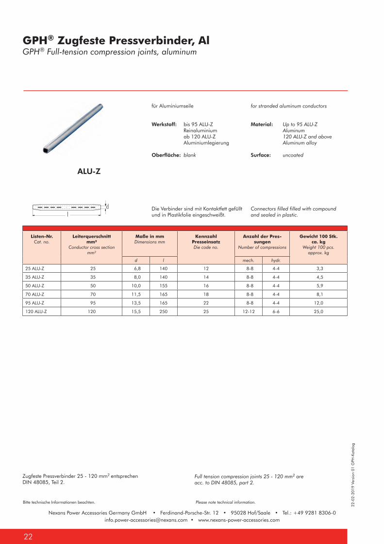
ALU-Z
Zugfeste Pressverbinder 25 - 120 mm2 entsprechen DIN 48085, Teil 2.
Full tension compression joints 25 - 120 mm2 are acc. to DIN 48085, part 2.
for stranded aluminum conductors
Material: Up to 95 ALU-Z Aluminum 120 ALU-Z and above Aluminum alloy
Surface: uncoated
Connectors filled filled with compound and sealed in plastic.
für Aluminiumseile
Werkstoff: bis 95 ALU-Z Reinaluminium ab 120 ALU-Z Aluminiumlegierung
Oberfläche: blank
Die Verbinder sind mit Kontaktfett gefüllt und in Plastikfolie eingeschweißt.
GPH® Zugfeste Pressverbinder, AlGPH® Full-tension compression joints, aluminum
Listen-Nr.Cat. no.
Leiterquerschnitt mm²
Conductor cross section mm²
Maße in mmDimensions mm
Kennzahl PresseinsatzDie code no.
Anzahl der Pres-sungen
Number of compressions
Gewicht 100 Stk. ca. kg
Weight 100 pcs. approx. kg
d l mech. hydr.
25 ALU-Z 25 6,8 140 12 8-8 4-4 3,3
35 ALU-Z 35 8,0 140 14 8-8 4-4 4,5
50 ALU-Z 50 10,0 155 16 8-8 4-4 5,9
70 ALU-Z 70 11,5 165 18 8-8 4-4 8,1
95 ALU-Z 95 13,5 165 22 8-8 4-4 12,0
120 ALU-Z 120 15,5 250 25 12-12 6-6 25,0
22-0
2-20
19 V
ersi
on 0
1 G
PH-K
atal
og
23
Bitte technische Informationen beachten. Please note technical information.
Nexans Power Accessories Germany GmbH • Ferdinand-Porsche-Str. 12 • 95028 Hof/Saale • Tel.: +49 9281 [email protected] • www.nexans-power-accessories.com
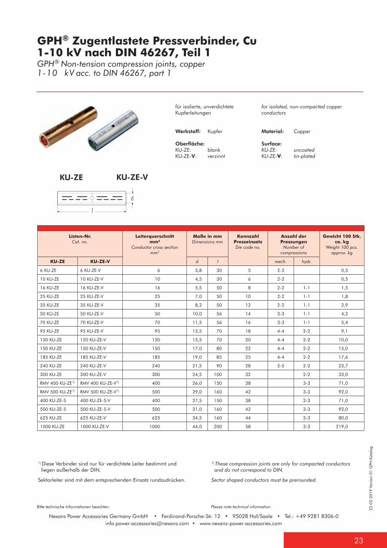
KU-ZE KU-ZE-V
Sektorleiter sind mit dem entsprechenden Einsatz rundzudrücken.
1) Diese Verbinder sind nur für verdichtete Leiter bestimmt und liegen außerhalb der DIN.
1) These compression joints are only for compacted conductors and do not correspond to DIN.
Sector shaped conductors must be prerounded.
for isolated, non-compacted copper conductors
Material: Copper
Surface:KU-ZE: uncoatedKU-ZE-V: tin-plated
für isolierte, unverdichtete Kupferleitungen
Werkstoff: Kupfer
Oberfläche:KU-ZE: blankKU-ZE-V: verzinnt
GPH® Zugentlastete Pressverbinder, Cu 1-10 kV nach DIN 46267, Teil 1 GPH® Non-tension compression joints, copper1-10 kV acc. to DIN 46267, part 1
Listen-Nr.Cat. no.
Leiterquerschnitt mm²
Conductor cross section mm²
Maße in mmDimensions mm
Kennzahl PresseinsatzDie code no.
Anzahl der Pressungen
Number of compressions
Gewicht 100 Stk. ca. kg
Weight 100 pcs. approx. kg
KU-ZE KU-ZE-V d l mech. hydr.
6 KU-ZE 6 KU-ZE-V 6 3,8 30 5 2-2 0,5
10 KU-ZE 10 KU-ZE-V 10 4,5 30 6 2-2 0,5
16 KU-ZE 16 KU-ZE-V 16 5,5 50 8 2-2 1-1 1,5
25 KU-ZE 25 KU-ZE-V 25 7,0 50 10 2-2 1-1 1,8
35 KU-ZE 35 KU-ZE-V 35 8,2 50 12 2-2 1-1 2,9
50 KU-ZE 50 KU-ZE-V 50 10,0 56 14 3-3 1-1 4,2
70 KU-ZE 70 KU-ZE-V 70 11,5 56 16 3-3 1-1 5,4
95 KU-ZE 95 KU-ZE-V 95 13,5 70 18 4-4 2-2 9,1
120 KU-ZE 120 KU-ZE-V 120 15,5 70 20 4-4 2-2 10,0
150 KU-ZE 150 KU-ZE-V 150 17,0 80 22 4-4 2-2 15,0
185 KU-ZE 185 KU-ZE-V 185 19,0 85 25 4-4 2-2 17,6
240 KU-ZE 240 KU-ZE-V 240 21,5 90 28 5-5 2-2 23,7
300 KU-ZE 300 KU-ZE-V 300 24,5 100 32 2-2 33,0
RMV 400 KU-ZE1) RMV 400 KU-ZE-V1) 400 26,0 150 38 3-3 71,0
RMV 500 KU-ZE1) RMV 500 KU-ZE-V1) 500 29,0 160 42 3-3 92,0
400 KU-ZE-S 400 KU-ZE-S-V 400 27,5 150 38 3-3 71,0
500 KU-ZE-S 500 KU-ZE-S-V 500 31,0 160 42 3-3 92,0
625 KU-ZE 625 KU-ZE-V 625 34,5 160 44 3-3 80,0
1000 KU-ZE 1000 KU-ZE-V 1000 44,0 200 58 3-3 219,0
Nexans Power Accessories Germany GmbH • Ferdinand-Porsche-Str. 12 • 95028 Hof/Saale • Tel.: +49 9281 [email protected] • www.nexans-power-accessories.com
22-0
2-20
19 V
ersi
on 0
1 G
PH-K
atal
og
Bitte technische Informationen beachten. Please note technical information.
Nexans Power Accessories Germany GmbH • Ferdinand-Porsche-Str. 12 • 95028 Hof/Saale • Tel.: +49 9281 [email protected] • www.nexans-power-accessories.com
24
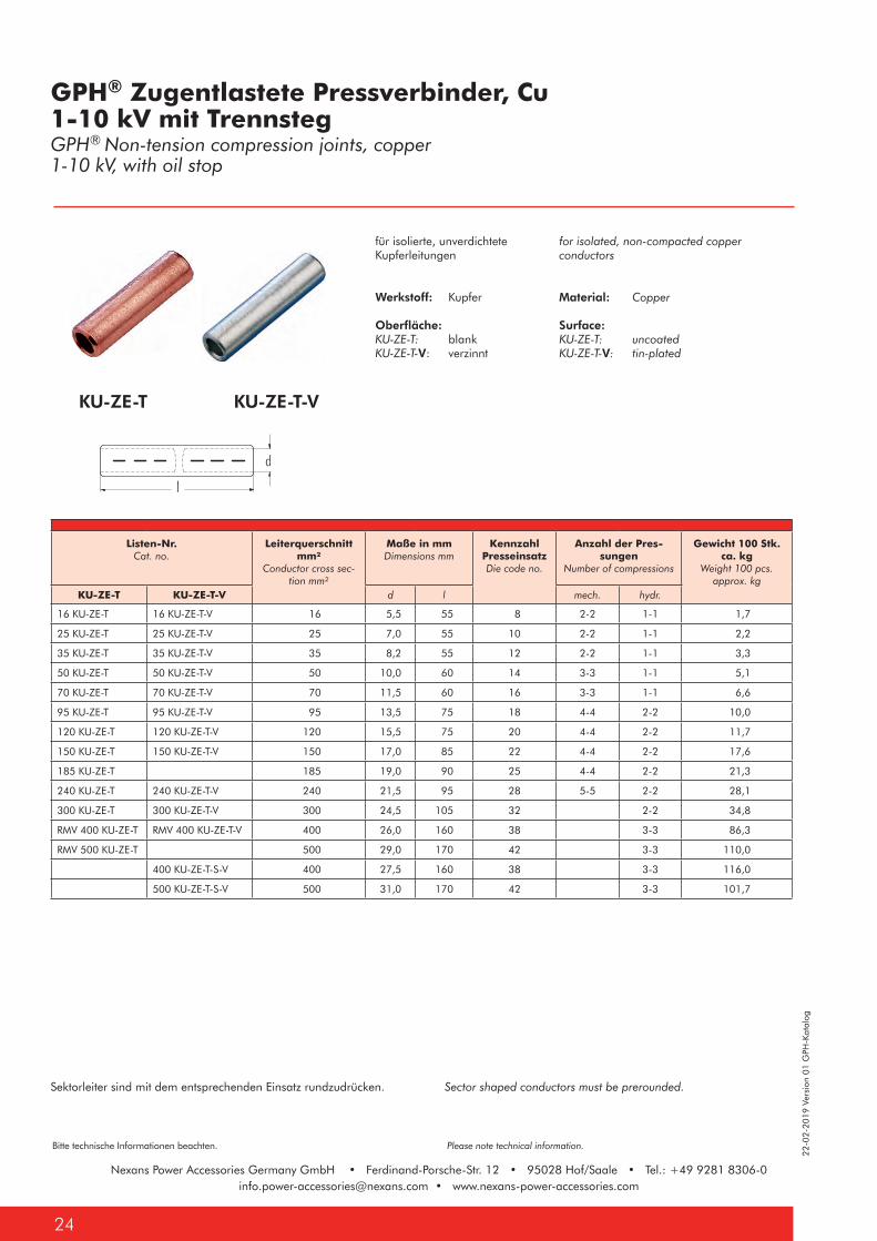
KU-ZE-T KU-ZE-T-V
Sektorleiter sind mit dem entsprechenden Einsatz rundzudrücken. Sector shaped conductors must be prerounded.
for isolated, non-compacted copper conductors
Material: Copper
Surface: KU-ZE-T: uncoatedKU-ZE-T-V: tin-plated
für isolierte, unverdichtete Kupferleitungen
Werkstoff: Kupfer
Oberfläche: KU-ZE-T: blankKU-ZE-T-V: verzinnt
GPH® Zugentlastete Pressverbinder, Cu1-10 kV mit Trennsteg GPH® Non-tension compression joints, copper1-10 kV, with oil stop
Listen-Nr.Cat. no.
Leiterquerschnitt mm²
Conductor cross sec-tion mm²
Maße in mmDimensions mm
Kennzahl PresseinsatzDie code no.
Anzahl der Pres-sungen
Number of compressions
Gewicht 100 Stk. ca. kg
Weight 100 pcs. approx. kg
KU-ZE-T KU-ZE-T-V d l mech. hydr.
16 KU-ZE-T 16 KU-ZE-T-V 16 5,5 55 8 2-2 1-1 1,7
25 KU-ZE-T 25 KU-ZE-T-V 25 7,0 55 10 2-2 1-1 2,2
35 KU-ZE-T 35 KU-ZE-T-V 35 8,2 55 12 2-2 1-1 3,3
50 KU-ZE-T 50 KU-ZE-T-V 50 10,0 60 14 3-3 1-1 5,1
70 KU-ZE-T 70 KU-ZE-T-V 70 11,5 60 16 3-3 1-1 6,6
95 KU-ZE-T 95 KU-ZE-T-V 95 13,5 75 18 4-4 2-2 10,0
120 KU-ZE-T 120 KU-ZE-T-V 120 15,5 75 20 4-4 2-2 11,7
150 KU-ZE-T 150 KU-ZE-T-V 150 17,0 85 22 4-4 2-2 17,6
185 KU-ZE-T 185 19,0 90 25 4-4 2-2 21,3
240 KU-ZE-T 240 KU-ZE-T-V 240 21,5 95 28 5-5 2-2 28,1
300 KU-ZE-T 300 KU-ZE-T-V 300 24,5 105 32 2-2 34,8
RMV 400 KU-ZE-T RMV 400 KU-ZE-T-V 400 26,0 160 38 3-3 86,3
RMV 500 KU-ZE-T 500 29,0 170 42 3-3 110,0
400 KU-ZE-T-S-V 400 27,5 160 38 3-3 116,0
500 KU-ZE-T-S-V 500 31,0 170 42 3-3 101,7
22-0
2-20
19 V
ersi
on 0
1 G
PH-K
atal
og
25
Bitte technische Informationen beachten. Please note technical information.
Nexans Power Accessories Germany GmbH • Ferdinand-Porsche-Str. 12 • 95028 Hof/Saale • Tel.: +49 9281 [email protected] • www.nexans-power-accessories.com
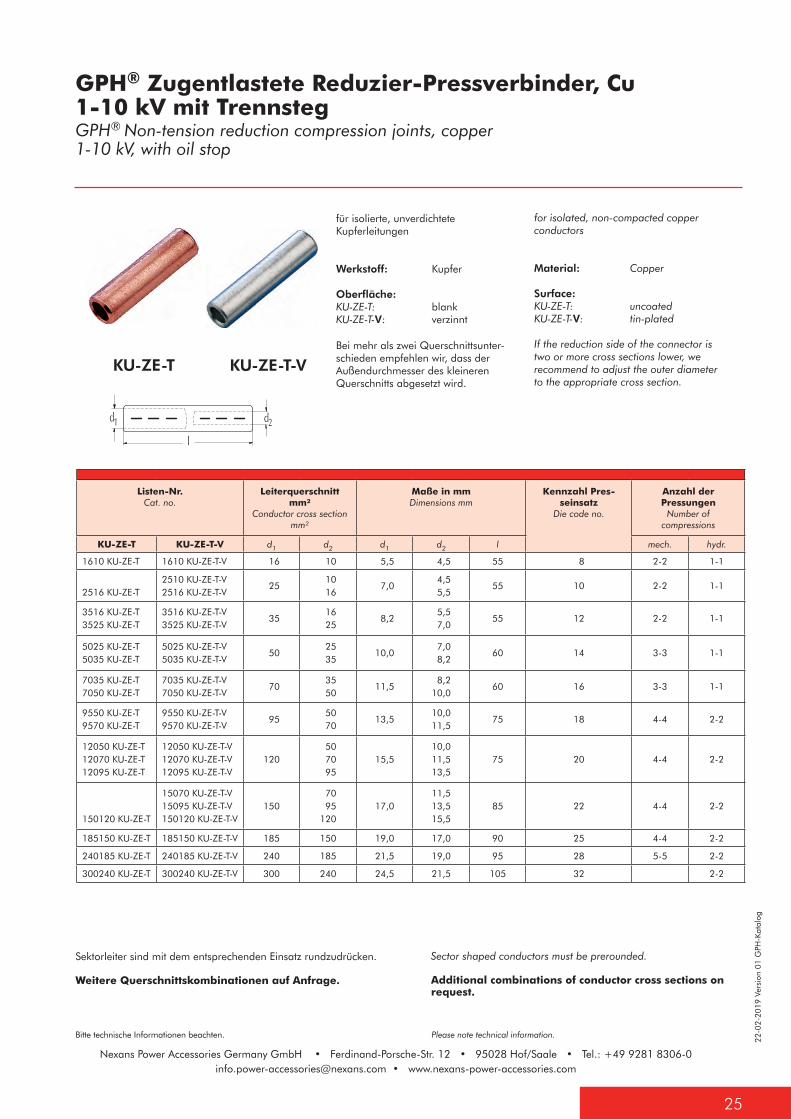
Sektorleiter sind mit dem entsprechenden Einsatz rundzudrücken.
Weitere Querschnittskombinationen auf Anfrage.
Sector shaped conductors must be prerounded.
Additional combinations of conductor cross sections on request.
KU-ZE-T KU-ZE-T-V
for isolated, non-compacted copper conductors
Material: Copper
Surface: KU-ZE-T: uncoatedKU-ZE-T-V: tin-plated
If the reduction side of the connector is two or more cross sections lower, we recommend to adjust the outer diameter to the appropriate cross section.
für isolierte, unverdichtete Kupferleitungen
Werkstoff: Kupfer
Oberfläche: KU-ZE-T: blankKU-ZE-T-V: verzinnt
Bei mehr als zwei Querschnittsunter-schieden empfehlen wir, dass der Außendurchmesser des kleineren Querschnitts abgesetzt wird.
GPH® Zugentlastete Reduzier-Pressverbinder, Cu1-10 kV mit Trennsteg GPH® Non-tension reduction compression joints, copper1-10 kV, with oil stop
Listen-Nr.Cat. no.
Leiterquerschnitt mm²
Conductor cross section mm²
Maße in mmDimensions mm
Kennzahl Pres-seinsatz
Die code no.
Anzahl der Pressungen
Number of compressions
KU-ZE-T KU-ZE-T-V d1 d2 d1 d2 l mech. hydr.
1610 KU-ZE-T 1610 KU-ZE-T-V 16 10 5,5 4,5 55 8 2-2 1-1
2516 KU-ZE-T2510 KU-ZE-T-V2516 KU-ZE-T-V
25 10 16
7,0 4,5 5,5
55 10 2-2 1-1
3516 KU-ZE-T3525 KU-ZE-T
3516 KU-ZE-T-V3525 KU-ZE-T-V
35 16 25
8,2 5,5 7,0
55 12 2-2 1-1
5025 KU-ZE-T5035 KU-ZE-T
5025 KU-ZE-T-V5035 KU-ZE-T-V
50 25 35
10,0 7,0 8,2
60 14 3-3 1-1
7035 KU-ZE-T7050 KU-ZE-T
7035 KU-ZE-T-V7050 KU-ZE-T-V
70 35 50
11,5 8,210,0
60 16 3-3 1-1
9550 KU-ZE-T9570 KU-ZE-T
9550 KU-ZE-T-V9570 KU-ZE-T-V
95 50 70
13,510,011,5
75 18 4-4 2-2
12050 KU-ZE-T12070 KU-ZE-T12095 KU-ZE-T
12050 KU-ZE-T-V12070 KU-ZE-T-V12095 KU-ZE-T-V
120 50 70 95
15,510,011,513,5
75 20 4-4 2-2
150120 KU-ZE-T
15070 KU-ZE-T-V15095 KU-ZE-T-V150120 KU-ZE-T-V
150 70 95120
17,011,513,515,5
85 22 4-4 2-2
185150 KU-ZE-T 185150 KU-ZE-T-V 185 150 19,0 17,0 90 25 4-4 2-2
240185 KU-ZE-T 240185 KU-ZE-T-V 240 185 21,5 19,0 95 28 5-5 2-2
300240 KU-ZE-T 300240 KU-ZE-T-V 300 240 24,5 21,5 105 32 2-2
Nexans Power Accessories Germany GmbH • Ferdinand-Porsche-Str. 12 • 95028 Hof/Saale • Tel.: +49 9281 [email protected] • www.nexans-power-accessories.com
22-0
2-20
19 V
ersi
on 0
1 G
PH-K
atal
og
Bitte technische Informationen beachten. Please note technical information.
Nexans Power Accessories Germany GmbH • Ferdinand-Porsche-Str. 12 • 95028 Hof/Saale • Tel.: +49 9281 [email protected] • www.nexans-power-accessories.com
26
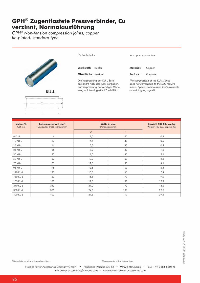
KU-L
for copper conductors
Material: Copper
Surface: tin-plated
The compression of the KU-L Series does not correspond to the DIN require-ments. Special compression tools available on catalogue page 47.
für Kupferleiter
Werkstoff: Kupfer
Oberfläche: verzinnt
Die Verpressung der KU-L Serieentspricht nicht den DIN Vorgaben.Zur Verpressung notwendiges Werk-zeug auf Katalogseite 47 erhältlich.
GPH® Zugentlastete Pressverbinder, Cuverzinnt, NormalausführungGPH® Non-tension compression joints, coppertin-plated, standard type
Listen-Nr.Cat. no.
Leiterquerschnitt mm² Conductor cross section mm²
Maße in mmDimensions mm
Gewicht 100 Stk. ca. kgWeight 100 pcs. approx. kg
d l
6 KU-L 6 3,5 25 0,4
10 KU-L 10 4,5 30 0,5
16 KU-L 16 5,5 35 0,9
25 KU-L 25 7,0 40 1,2
35 KU-L 35 8,5 45 2,1
50 KU-L 50 10,0 50 2,8
70 KU-L 70 12,0 55 4,1
95 KU-L 95 13,5 60 5,4
120 KU-L 120 15,0 65 7,4
150 KU-L 150 16,5 70 9,0
185 KU-L 185 19,0 80 12,2
240 KU-L 240 21,0 90 15,2
300 KU-L 300 24,0 100 22,8
400 KU-L 400 27,5 110 29,6
22-0
2-20
19 V
ersi
on 0
1 G
PH-K
atal
og
27
Bitte technische Informationen beachten. Please note technical information.
Nexans Power Accessories Germany GmbH • Ferdinand-Porsche-Str. 12 • 95028 Hof/Saale • Tel.: +49 9281 [email protected] • www.nexans-power-accessories.com
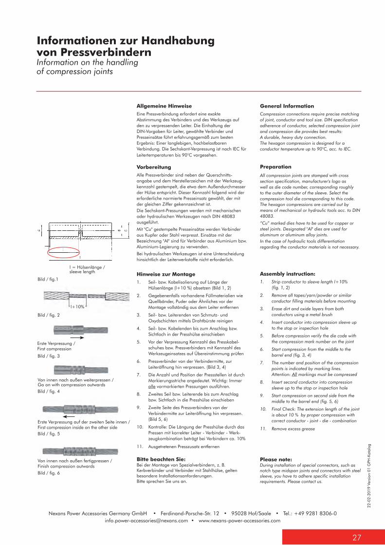
Allgemeine HinweiseEine Pressverbindung erfordert eine exakte Abstimmung des Verbinders und des Werkzeugs auf den zu verpressenden Leiter. Die Einhaltung der DIN-Vorgaben für Leiter, gewählte Verbinder und Presseinsätze führt erfahrungsgemäß zum besten Ergebnis: Einer langlebigen, hochbelastbaren Verbindung. Die Sechskant-Verpressung ist nach IEC für Leitertemperaturen bis 90°C vorgesehen.
VorbereitungAlle Pressverbinder sind neben der Querschnitts-angabe und dem Herstellerzeichen mit der Werkzeug-kennzahl gestempelt, die etwa dem Außendurchmesser der Hülse entspricht. Dieser Kennzahl folgend wird der erforderliche normierte Presseinsatz gewählt, der mit der gleichen Ziffer gekennzeichnet ist.Die Sechskant-Pressungen werden mit mechanischen oder hydraulischen Werkzeugen nach DIN 48083 ausgeführt.
Mit "Cu" gestempelte Presseinsätze werden Verbinder aus Kupfer oder Stahl verpresst. Einsätze mit der Bezeichnung "AI" sind für Verbinder aus Aluminium bzw. Aluminium-Legierung zu verwenden.
Bei hydraulischen Werkzeugen ist eine Unterscheidung hinsichtlich der Leiterwerkstoffe nicht erforderlich.
Hinweise zur Montage1. Seil- bzw. Kabelisolierung auf Länge der
Hülsenlänge (l+10 %) absetzen (Bild 1, 2)
2. Gegebenenfalls vorhandene Füllmaterialien wie Quellbänder, Puder oder Ähnliches vor der Montage vollständig aus dem Leiter entfernen
3. Seil- bzw. Leiterenden von Schmutz- und Oxydschichten mittels Drahtbürste reinigen
4. Seil- bzw. Kabelenden bis zum Anschlag bzw. Sichtloch in der Presshülse einschieben
5. Vor der Verpressung Kennzahl des Presskabel-schuhes bzw. Pressverbinders mit Kennzahl des Werkzeugeinsatzes auf Übereinstimmung prüfen
6. Pressverbinder von der Verbindermitte, zur Leiteröffnung hin verpressen. (Bild 3, 4)
7. Die Anzahl und Position der Pressstellen ist durch Markierungsstriche angedeutet. Wichtig: Immer alle vormarkierten Pressungen ausführen.
8. Zweites Seil bzw. Leiterende bis zum Anschlagbzw. Sichtloch in die Presshülse einschieben
9. Zweite Seite des Pressverbinders von der Verbindermitte zur Leiteröffnung hin verpressen. (Bild 5, 6)
10. Kontrolle: Die Längung der Presshülse durch das Pressen mit korrekter Leiter - Verbinder - Werk-zeugkombination beträgt bei Verbindern ca. 10%
11. Ausgetretenen Presszusatz entfernen
General Information Compression connections require precise matching of joint, conductor and tool size. DIN specification adherence of conductor, selected compression joint and compression die provides best results: A durable, heavy duty connection. The hexagon compression is designed for a conductor temperature up to 90°C, acc. to IEC.
Preparation
All compression joints are stamped with cross section specification, manufacturer's logo as well as die code number, corresponding roughly to the outer diameter of the sleeve. Select the compression tool die corresponding to this code.The hexagon compressions are carried out by means of mechanical or hydraulic tools acc. to DIN 48083.
“Cu” marked dies have to be used for copper or steel joints. Designated "Al" dies are used for aluminum or aluminum alloy joints.In the case of hydraulic tools differentiation regarding the conductor materials is not necessary.
Assembly instruction:1. Strip conductor to sleeve length l+10%
(fig. 1, 2)
2. Remove all tapes/yarn/powder or similar conductor filling materials before mounting
3. Erase dirt and oxide layers from both conductors using a metal brush
4. Insert conductor into compression sleeve up to the stop or inspection hole
5. Before compression verify the die code with the compression mark number on the joint
6. Start compression from the middle to the barrel end (fig. 3, 4)
7. The number and position of the compression points is indicated by marking lines. Attention: All markings must be compressed
8. Insert second conductor into compression sleeve up to the stop or inspection hole
9. Start compression on second side from the middle to the barrel end (fig. 5, 6)
10. Final Check: The extension length of the joint is about 10 % by proper compression with correct conductor - joint - die - combination
11. Remove excess grease
Informationen zur Handhabung von PressverbindernInformation on the handlingof compression joints
l = Hülsenlänge / sleeve length
l+10%
Bitte beachten Sie:Bei der Montage von Spezialverbindern, z. B. Kerbverbinder und Verbinder mit Stahlhülse, gelten besondere Installationsanforderungen. Bitte sprechen Sie uns an.
Please note:During installation of special connectors, such as notch type midspan joints and connectors with steel sleeve, you have to adhere specific installation requirements. Please contact us.
Bild / fig. 3
Bild / fig. 4
Bild / fig. 5
Bild / fig. 6
Von innen nach außen fertigpressen /Finish compression outwards
Erste Verpressung auf der zweiten Seite innen /First compression inside on the other side
Von innen nach außen weiterpressen /Go on with compression outwards
Erste Verpressung / First compression
Bild / fig. 2
Bild / fig.1
Nexans Power Accessories Germany GmbH • Ferdinand-Porsche-Str. 12 • 95028 Hof/Saale • Tel.: +49 9281 [email protected] • www.nexans-power-accessories.com
22-0
2-20
19 V
ersi
on 0
1 G
PH-K
atal
og
Bitte technische Informationen beachten. Please note technical information.
Nexans Power Accessories Germany GmbH • Ferdinand-Porsche-Str. 12 • 95028 Hof/Saale • Tel.: +49 9281 [email protected] • www.nexans-power-accessories.com
28
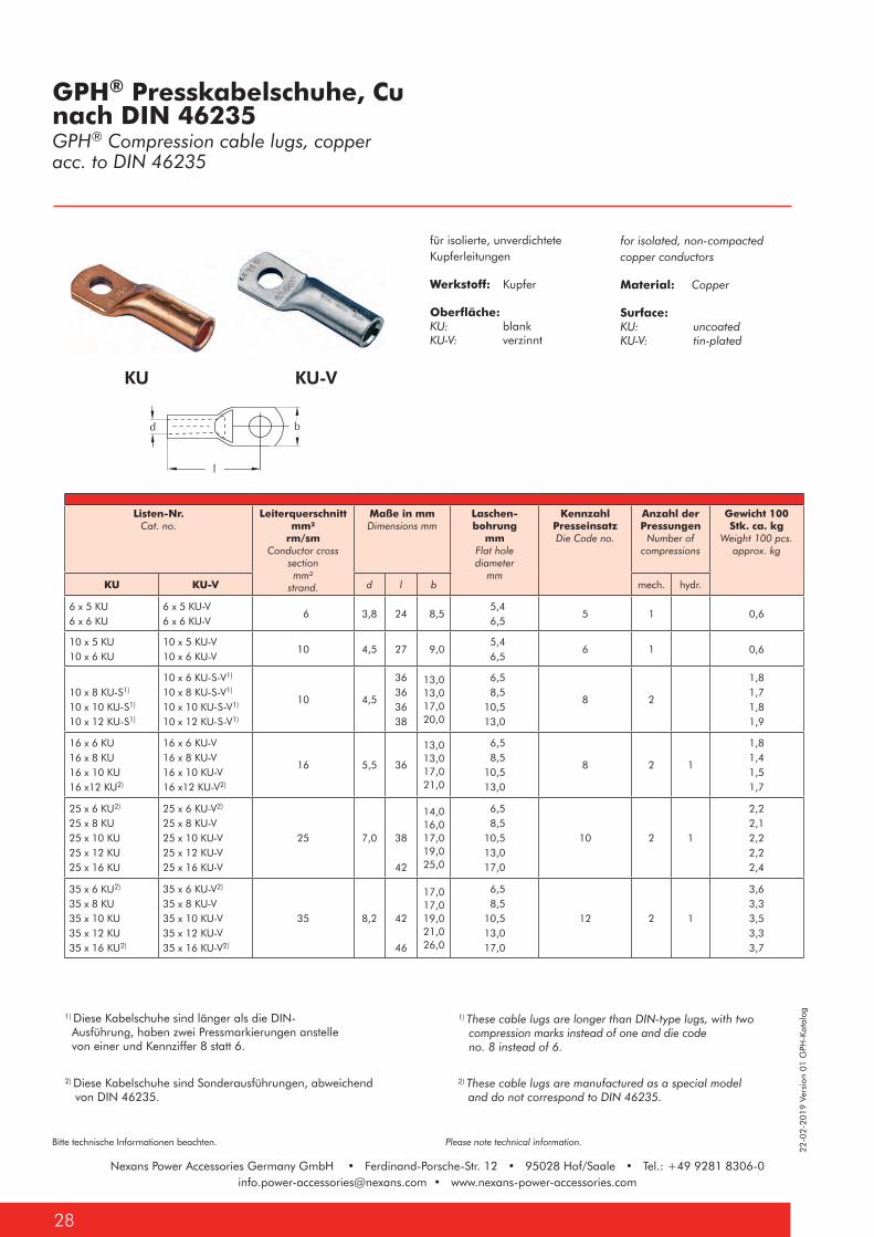
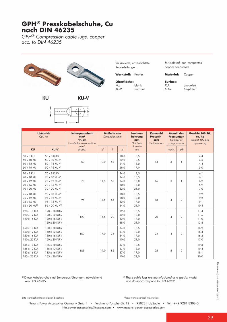
KU-V
1) Diese Kabelschuhe sind länger als die DIN- Ausführung, haben zwei Pressmarkierungen anstelle von einer und Kennziffer 8 statt 6.
1) These cable lugs are longer than DIN-type lugs, with two compression marks instead of one and die code no. 8 instead of 6.
KU
2) These cable lugs are manufactured as a special model and do not correspond to DIN 46235.
2) Diese Kabelschuhe sind Sonderausführungen, abweichend von DIN 46235.
for isolated, non-compacted copper conductors
Material: Copper
Surface: KU: uncoatedKU-V: tin-plated
für isolierte, unverdichtete Kupferleitungen
Werkstoff: Kupfer
Oberfläche: KU: blankKU-V: verzinnt
GPH® Presskabelschuhe, Cu nach DIN 46235GPH® Compression cable lugs, copper acc. to DIN 46235
Listen-Nr.Cat. no.
Leiterquerschnitt mm²
rm/smConductor cross
section mm²
strand.
Maße in mmDimensions mm
Laschen-bohrung
mmFlat hole diameter
mm
Kennzahl PresseinsatzDie Code no.
Anzahl der Pressungen
Number of compressions
Gewicht 100 Stk. ca. kg
Weight 100 pcs. approx. kg
KU KU-V d l b mech. hydr.
6 x 5 KU6 x 6 KU
6 x 5 KU-V6 x 6 KU-V
6 3,8 24 8,5 5,4 6,5
5 1 0,6
10 x 5 KU10 x 6 KU
10 x 5 KU-V10 x 6 KU-V
10 4,5 27 9,0 5,4 6,5
6 1 0,6
10 x 8 KU-S1)
10 x 10 KU-S1)
10 x 12 KU-S1)
10 x 6 KU-S-V1)
10 x 8 KU-S-V1)
10 x 10 KU-S-V1)
10 x 12 KU-S-V1)
10 4,5
36363638
13,013,017,020,0
6,5 8,510,513,0
8 2
1,81,71,81,9
16 x 6 KU16 x 8 KU16 x 10 KU16 x12 KU2)
16 x 6 KU-V16 x 8 KU-V16 x 10 KU-V16 x12 KU-V2)
16 5,5 36
13,013,017,021,0
6,5 8,510,513,0
8 2 1
1,81,41,51,7
25 x 6 KU2)
25 x 8 KU25 x 10 KU25 x 12 KU25 x 16 KU
25 x 6 KU-V2)
25 x 8 KU-V25 x 10 KU-V25 x 12 KU-V25 x 16 KU-V
25 7,0 38
42
14,016,017,019,025,0
6,5 8,510,513,017,0
10 2 1
2,22,12,22,22,4
35 x 6 KU2)
35 x 8 KU35 x 10 KU35 x 12 KU35 x 16 KU2)
35 x 6 KU-V2)
35 x 8 KU-V35 x 10 KU-V35 x 12 KU-V35 x 16 KU-V2)
35 8,2 42
46
17,017,019,021,026,0
6,5 8,510,513,017,0
12 2 1
3,63,33,53,33,7
22-0
2-20
19 V
ersi
on 0
1 G
PH-K
atal
og
29
Bitte technische Informationen beachten. Please note technical information.
Nexans Power Accessories Germany GmbH • Ferdinand-Porsche-Str. 12 • 95028 Hof/Saale • Tel.: +49 9281 [email protected] • www.nexans-power-accessories.com
Listen-Nr.Cat. no.
Leiterquerschnitt mm²
rm/smConductor cross section
mm² strand.
Maße in mmDimensions mm
Laschen-bohrung
mmFlat hole diameter
mm
Kennzahl Pressein-
satzDie Code no.
Anzahl der Pressungen
Number of compressions
Gewicht 100 Stk. ca. kg
Weight 100 pcs. approx. kg
KU KU-V d l b mech. hydr.
50 x 8 KU50 x 10 KU50 x 12 KU50 x 16 KU
50 x 8 KU-V50 x 10 KU-V50 x 12 KU-V50 x 16 KU-V
50 10,0 52
20,022,024,028,0
8,510,513,017,0
14 3 1
4,4 4,5 4,4 5,0
70 x 8 KU70 x 10 KU70 x 12 KU70 x 16 KU70 x 20 KU
70 x 8 KU-V70 x 10 KU-V70 x 12 KU-V70 x 16 KU-V70 x 20 KU-V
70 11,5 55
24,024,024,030,032,0
8,510,513,017,021,0
16 3 1
6,1 6,1 6,2 5,9 7,0
95 x 10 KU95 x 12 KU95 x 16 KU95 x 20 KU2)
95 x 10 KU-V95 x 12 KU-V95 x 16 KU-V95 x 20 KU-V2)
95 13,5 65
28,028,032,034,0
10,513,017,021,0
18 4 2
9,2 9,2 9,110,4
120 x 10 KU120 x 12 KU120 x 16 KU
120 x 10 KU-V120 x 12 KU-V120 x 16 KU-V120 x 20 KU-V
120 15,5 70
32,032,032,038,0
10,513,017,021,0
20 4 2
11,411,611,012,8
150 x 10 KU150 x 12 KU150 x 16 KU150 x 20 KU
150 x 10 KU-V150 x 12 KU-V150 x 16 KU-V150 x 20 KU-V
150 17,0 78
34,034,034,040,0
10,513,017,021,0
22 4 2
16,916,416,317,0
185 x 10 KU185 x 12 KU185 x 16 KU185 x 20 KU
185 x 10 KU-V185 x 12 KU-V185 x 16 KU-V185 x 20 KU-V
185 19,0 82
37,037,037,040,0
10,513,017,021,0
25 5 2
19,319,419,120,0
KU KU-V
2) Diese Kabelschuhe sind Sonderausführungen, abweichend von DIN 46235.
2) These cable lugs are manufactured as a special model and do not correspond to DIN 46235.
GPH® Presskabelschuhe, Cu nach DIN 46235GPH® Compression cable lugs, copper acc. to DIN 46235
for isolated, non-compacted copper conductors
Material: Copper
Surface: KU: uncoatedKU-V: tin-plated
für isolierte, unverdichtete Kupferleitungen
Werkstoff: Kupfer
Oberfläche: KU: blankKU-V: verzinnt
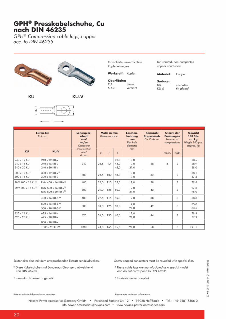
Nexans Power Accessories Germany GmbH • Ferdinand-Porsche-Str. 12 • 95028 Hof/Saale • Tel.: +49 9281 [email protected] • www.nexans-power-accessories.com
22-0
2-20
19 V
ersi
on 0
1 G
PH-K
atal
og
Bitte technische Informationen beachten. Please note technical information.
Nexans Power Accessories Germany GmbH • Ferdinand-Porsche-Str. 12 • 95028 Hof/Saale • Tel.: +49 9281 [email protected] • www.nexans-power-accessories.com
30
KU KU-V
2) These cable lugs are manufactured as a special model and do not correspond to DIN 46235.
3) Inside diameter adapted.
2) Diese Kabelschuhe sind Sonderausführungen, abweichend von DIN 46235.
3) Innendurchmesser angepaßt.
Sektorleiter sind mit dem entsprechenden Einsatz rundzudrücken. Sector shaped conductors must be rounded with special dies.
GPH® Presskabelschuhe, Cu nach DIN 46235GPH® Compression cable lugs, copper acc. to DIN 46235
Listen-Nr.Cat. no.
Leiterquer-schnitt mm²
rm/smConductor
cross section mm²
strand.
Maße in mmDimensions mm
Laschen-bohrung
mmFlat hole diameter
mm
Kennzahl PresseinsatzDie Code no.
Anzahl der Pressungen
Number of compressions
Gewicht 100 Stk. ca. kg
Weight 100 pcs. approx. kg
KU KU-V d l b mech. hydr.
240 x 12 KU240 x 16 KU240 x 20 KU
240 x 12 KU-V240 x 16 KU-V240 x 20 KU-V
240 21,5 9242,042,045,0
13,017,021,0
28 5 2 28,5 28,9 28,0
300 x 12 KU2)
300 x 16 KU300 x 12 KU-V2)
300 x 16 KU-V300 24,5 100 48,0
13,017,0
32 2 38,1 37,5
RMV 400 x 16 KU3) RMV 400 x 16 KU-V3) 400 26,0 115 55,0 17,0 38 3 79,8
RMV 500 x 16 KU3) RMV 500 x 16 KU-V3)
RMV 500 x 20 KU-V3) 500 29,0 125 60,017,021,0
42 3 97,8 96,0
400 x 16 KU-S-V 400 27,5 115 55,0 17,0 38 3 68,8
500 x 16 KU-S-V
500 x 20 KU-S-V500 31,0 125 60,0
17,021,0
42 3 85,0 83,5
625 x 16 KU625 x 20 KU
625 x 16 KU-V625 x 20 KU-V
625 34,5 135 60,017,021,0
44 3 79,4 77,9
800 x 20 KU-V
1000 x 20 KU-V 1000 44,0 165 85,0 21,0 58 3 191,1
for isolated, non-compacted copper conductors
Material: Copper
Surface: KU: uncoatedKU-V: tin-plated
für isolierte, unverdichtete Kupferleitungen
Werkstoff: Kupfer
Oberfläche: KU: blankKU-V: verzinnt
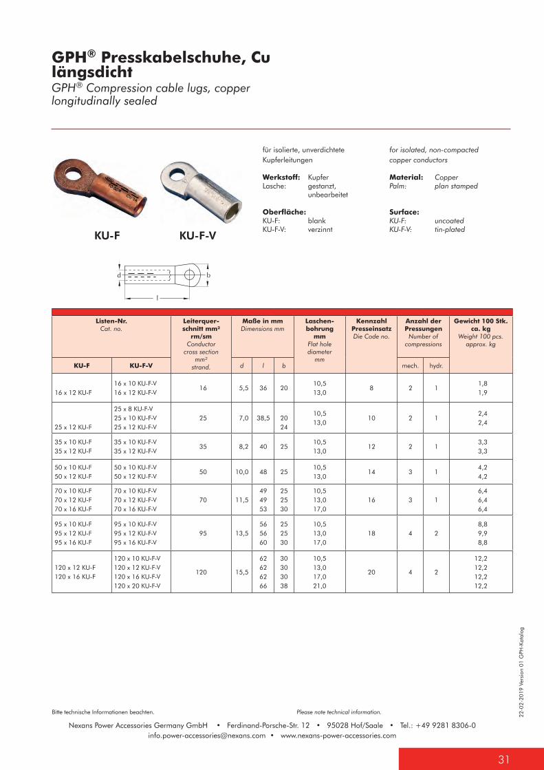
22-0
2-20
19 V
ersi
on 0
1 G
PH-K
atal
og
31
Bitte technische Informationen beachten. Please note technical information.
Nexans Power Accessories Germany GmbH • Ferdinand-Porsche-Str. 12 • 95028 Hof/Saale • Tel.: +49 9281 [email protected] • www.nexans-power-accessories.com
KU-F KU-F-V
for isolated, non-compacted copper conductors
Material: CopperPalm: plan stamped
Surface: KU-F: uncoatedKU-F-V: tin-plated
für isolierte, unverdichtete Kupferleitungen
Werkstoff: KupferLasche: gestanzt, unbearbeitet
Oberfläche:KU-F: blankKU-F-V: verzinnt
GPH® Presskabelschuhe, CulängsdichtGPH® Compression cable lugs, copper longitudinally sealed
Listen-Nr.Cat. no.
Leiterquer-schnitt mm²
rm/smConductor
cross section mm²
strand.
Maße in mmDimensions mm
Laschen-bohrung
mmFlat hole diameter
mm
Kennzahl PresseinsatzDie Code no.
Anzahl der Pressungen
Number of compressions
Gewicht 100 Stk. ca. kg
Weight 100 pcs. approx. kg
KU-F KU-F-V d l b mech. hydr.
16 x 12 KU-F16 x 10 KU-F-V16 x 12 KU-F-V
16 5,5 36 2010,513,0
8 2 1 1,8 1,9
25 x 12 KU-F
25 x 8 KU-F-V25 x 10 KU-F-V25 x 12 KU-F-V
25 7,0 38,5 2024
10,513,0
10 2 1 2,4 2,4
35 x 10 KU-F35 x 12 KU-F
35 x 10 KU-F-V35 x 12 KU-F-V
35 8,2 40 2510,513,0
12 2 1 3,3 3,3
50 x 10 KU-F50 x 12 KU-F
50 x 10 KU-F-V50 x 12 KU-F-V
50 10,0 48 2510,513,0
14 3 1 4,2 4,2
70 x 10 KU-F70 x 12 KU-F70 x 16 KU-F
70 x 10 KU-F-V70 x 12 KU-F-V70 x 16 KU-F-V
70 11,5494953
252530
10,513,017,0
16 3 1 6,4 6,4 6,4
95 x 10 KU-F95 x 12 KU-F95 x 16 KU-F
95 x 10 KU-F-V95 x 12 KU-F-V95 x 16 KU-F-V
95 13,5565660
252530
10,513,017,0
18 4 2 8,8 9,9 8,8
120 x 12 KU-F120 x 16 KU-F
120 x 10 KU-F-V120 x 12 KU-F-V120 x 16 KU-F-V120 x 20 KU-F-V
120 15,5
62626266
30303038
10,513,017,021,0
20 4 2
12,212,212,212,2
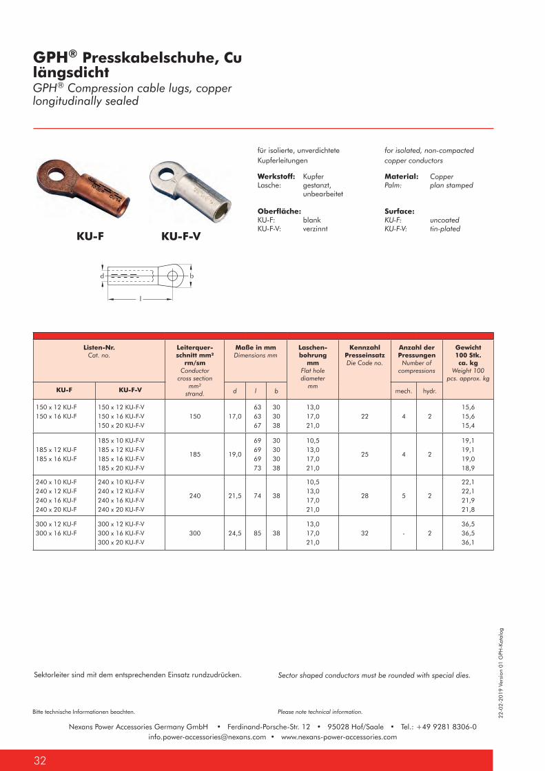
Nexans Power Accessories Germany GmbH • Ferdinand-Porsche-Str. 12 • 95028 Hof/Saale • Tel.: +49 9281 [email protected] • www.nexans-power-accessories.com
22-0
2-20
19 V
ersi
on 0
1 G
PH-K
atal
og
Bitte technische Informationen beachten. Please note technical information.
Nexans Power Accessories Germany GmbH • Ferdinand-Porsche-Str. 12 • 95028 Hof/Saale • Tel.: +49 9281 [email protected] • www.nexans-power-accessories.com
32
KU-F KU-F-V
GPH® Presskabelschuhe, CulängsdichtGPH® Compression cable lugs, copperlongitudinally sealed
Listen-Nr.Cat. no.
Leiterquer-schnitt mm²
rm/smConductor
cross section mm²
strand.
Maße in mmDimensions mm
Laschen-bohrung
mmFlat hole diameter
mm
Kennzahl PresseinsatzDie Code no.
Anzahl der Pressungen
Number of compressions
Gewicht 100 Stk. ca. kg
Weight 100 pcs. approx. kg
KU-F KU-F-V d l b mech. hydr.
150 x 12 KU-F150 x 16 KU-F
150 x 12 KU-F-V150 x 16 KU-F-V150 x 20 KU-F-V
150 17,0 63 63 67
303038
13,017,021,0
22 4 215,615,615,4
185 x 12 KU-F185 x 16 KU-F
185 x 10 KU-F-V185 x 12 KU-F-V185 x 16 KU-F-V185 x 20 KU-F-V
185 19,0
69 69 69 73
30303038
10,513,017,021,0
25 4 2
19,119,119,018,9
240 x 10 KU-F240 x 12 KU-F240 x 16 KU-F240 x 20 KU-F
240 x 10 KU-F-V240 x 12 KU-F-V240 x 16 KU-F-V240 x 20 KU-F-V
240 21,5 74 38
10,513,017,021,0
28 5 2
22,122,121,921,8
300 x 12 KU-F300 x 16 KU-F
300 x 12 KU-F-V300 x 16 KU-F-V300 x 20 KU-F-V
300 24,5 85 3813,017,021,0
32 - 236,536,536,1
Sector shaped conductors must be rounded with special dies.Sektorleiter sind mit dem entsprechenden Einsatz rundzudrücken.
for isolated, non-compacted copper conductors
Material: CopperPalm: plan stamped
Surface: KU-F: uncoatedKU-F-V: tin-plated
für isolierte, unverdichtete Kupferleitungen
Werkstoff: KupferLasche: gestanzt, unbearbeitet
Oberfläche:KU-F: blankKU-F-V: verzinnt

22-0
2-20
19 V
ersi
on 0
1 G
PH-K
atal
og
33
Bitte technische Informationen beachten. Please note technical information.
Nexans Power Accessories Germany GmbH • Ferdinand-Porsche-Str. 12 • 95028 Hof/Saale • Tel.: +49 9281 [email protected] • www.nexans-power-accessories.com
KU-L KU-L-S
for isolated, non-compacted copper conductors
Material: Copper
Surface: tin-plated
KU-L: without inspection holeKU-L-S: with inspection hole
The compression of the KU-L Series does not accord to the DIN require-ments. Special compression tools are available on catalogue page 47.
für isolierte, unverdichtete Kupferleitungen
Werkstoff: Kupfer
Oberfläche: verzinnt
KU-L: ohne SichtlochKU-L-S: mit Sichtloch
Die Verpressung der KU-L Serieentspricht nicht den DIN Vorgaben.Zur Verpressung notwendiges Werk-zeug auf Katalogseite 47 erhältlich.
GPH® Presskabelschuhe Cu, Normalausführung, mit und ohne Sichtloch, galvanisch verzinntGPH® Compression cable lugs, copper, standard type,with and without inspection hole, tin-plated
Listen-Nr.Cat. no.
Leiterquerschnitt mm² rm/sm
Conductor cross section mm² strand.
Maße in mmDimensions mm
Laschenbohrung mm
Flat hole diameter mm
Gewicht 100 Stk. ca. kg
Weight 100 pcs. approx. kgKU-L KU-L-S d a l b
6 x 5 KU-L6 x 6 KU-L6 x 8 KU-L6 x 10 KU-L
6 x 5 KU-L-S6 x 6 KU-L-S6 x 8 KU-L-S6 x 10 KU-L-S
6 3,5 9
21212121
10,511,515,517,0
5,4 6,5 8,510,5
0,40,40,40,5
10 x 5 KU-L10 x 6 KU-L10 x 8 KU-L10 x 10 KU-L
10 x 5 KU-L-S10 x 6 KU-L-S10 x 8 KU-L-S10 x 10 KU-L-S
10 4,5 9
212123
25,5
12,012,014,517,0
5,5 6,5 8,510,5
0,40,40,40,5
16 x 5 KU-L16 x 6 KU-L16 x 8 KU-L16 x 10 KU-L16 x 12 KU-L
16 x 5 KU-L-S16 x 6 KU-L-S16 x 8 KU-L-S16 x 10 KU-L-S16 x 12 KU-L-S
16 5,5 12
2626283032
12,012,013,517,020,0
5,5 6,5 8,510,513,0
0,50,70,80,80,8
25 x 6 KU-L25 x 8 KU-L25 x 10 KU-L25 x 12 KU-L
25 x 6 KU-L-S25 x 8 KU-L-S25 x 10 KU-L-S25 x 12 KU-L-S
25 7,0 13
27293334
14,016,017,520,0
6,5 8,510,513,0
1,01,01,11,0
35 x 6 KU-L35 x 8 KU-L35 x 10 KU-L35 x 12 KU-L
35 x 6 KU-L-S35 x 8 KU-L-S35 x 10 KU-L-S35 x 12 KU-L-S
35 8,5 15
31323437
18,018,018,022,0
6,5 8,510,513,0
1,01,01,11,0
50 x 8 KU-L50 x 10 KU-L50 x 12 KU-L50 x 16 KU-L
50 x 8 KU-L-S50 x 10 KU-L-S50 x 12 KU-L-S
50 10,0 16
36393946
20,021,021,026,0
8,510,513,017,0
3,13,23,33,2
70 x 8 KU-L70 x 10 KU-L70 x 12 KU-L70 x 16 KU-L
70 x 8 KU-L-S70 x 10 KU-L-S70 x 12 KU-L-S70 x 16 KU-L-S
70 12,0 19
41404250
23,023,023,029,0
8,510,513,017,0
3,53,63,63,6
Sector shaped conductors must be rounded with special dies.Sektorleiter sind mit dem entsprechenden Einsatz rundzudrücken.
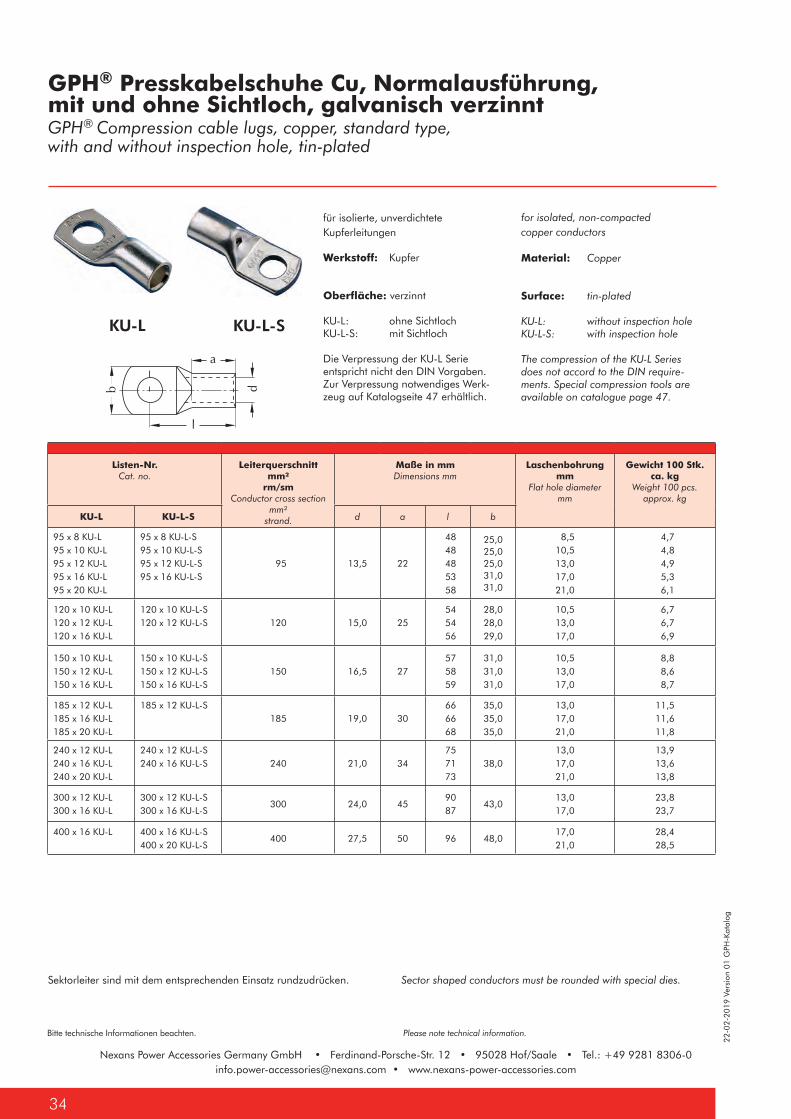
Nexans Power Accessories Germany GmbH • Ferdinand-Porsche-Str. 12 • 95028 Hof/Saale • Tel.: +49 9281 [email protected] • www.nexans-power-accessories.com
22-0
2-20
19 V
ersi
on 0
1 G
PH-K
atal
og
Bitte technische Informationen beachten. Please note technical information.
Nexans Power Accessories Germany GmbH • Ferdinand-Porsche-Str. 12 • 95028 Hof/Saale • Tel.: +49 9281 [email protected] • www.nexans-power-accessories.com
34
KU-L KU-L-S
for isolated, non-compacted copper conductors
Material: Copper
Surface: tin-plated
KU-L: without inspection holeKU-L-S: with inspection hole
The compression of the KU-L Series does not accord to the DIN require-ments. Special compression tools are available on catalogue page 47.
für isolierte, unverdichtete Kupferleitungen
Werkstoff: Kupfer
Oberfläche: verzinnt
KU-L: ohne SichtlochKU-L-S: mit Sichtloch
Die Verpressung der KU-L Serieentspricht nicht den DIN Vorgaben.Zur Verpressung notwendiges Werk-zeug auf Katalogseite 47 erhältlich.
GPH® Presskabelschuhe Cu, Normalausführung, mit und ohne Sichtloch, galvanisch verzinntGPH® Compression cable lugs, copper, standard type,with and without inspection hole, tin-plated
Listen-Nr.Cat. no.
Leiterquerschnitt mm²
rm/smConductor cross section
mm² strand.
Maße in mmDimensions mm
Laschenbohrung mm
Flat hole diameter mm
Gewicht 100 Stk. ca. kg
Weight 100 pcs. approx. kg
KU-L KU-L-S d a l b
95 x 8 KU-L95 x 10 KU-L95 x 12 KU-L95 x 16 KU-L95 x 20 KU-L
95 x 8 KU-L-S95 x 10 KU-L-S95 x 12 KU-L-S95 x 16 KU-L-S
95 13,5 22
48 48 48 53 58
25,025,025,031,031,0
8,510,513,017,021,0
4,7 4,8 4,9 5,3 6,1
120 x 10 KU-L120 x 12 KU-L120 x 16 KU-L
120 x 10 KU-L-S120 x 12 KU-L-S 120 15,0 25
54 54 56
28,028,029,0
10,513,017,0
6,7 6,7 6,9
150 x 10 KU-L150 x 12 KU-L150 x 16 KU-L
150 x 10 KU-L-S150 x 12 KU-L-S150 x 16 KU-L-S
150 16,5 27 57 58 59
31,031,031,0
10,513,017,0
8,8 8,6 8,7
185 x 12 KU-L185 x 16 KU-L185 x 20 KU-L
185 x 12 KU-L-S185 19,0 30
66 66 68
35,035,035,0
13,017,021,0
11,511,611,8
240 x 12 KU-L240 x 16 KU-L240 x 20 KU-L
240 x 12 KU-L-S240 x 16 KU-L-S 240 21,0 34
75 71 73
38,013,017,021,0
13,913,613,8
300 x 12 KU-L300 x 16 KU-L
300 x 12 KU-L-S300 x 16 KU-L-S
300 24,0 45 90 87
43,013,017,0
23,823,7
400 x 16 KU-L 400 x 16 KU-L-S400 x 20 KU-L-S
400 27,5 50 96 48,017,021,0
28,428,5
Sector shaped conductors must be rounded with special dies.Sektorleiter sind mit dem entsprechenden Einsatz rundzudrücken.
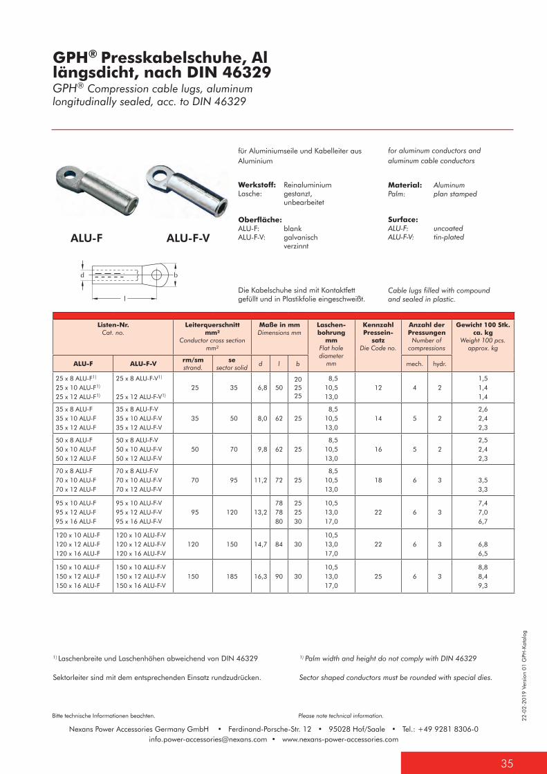
22-0
2-20
19 V
ersi
on 0
1 G
PH-K
atal
og
35
Bitte technische Informationen beachten. Please note technical information.
Nexans Power Accessories Germany GmbH • Ferdinand-Porsche-Str. 12 • 95028 Hof/Saale • Tel.: +49 9281 [email protected] • www.nexans-power-accessories.com
Sector shaped conductors must be rounded with special dies.Sektorleiter sind mit dem entsprechenden Einsatz rundzudrücken.
ALU-F-VALU-F
for aluminum conductors and aluminum cable conductors
Material: AluminumPalm: plan stamped
Surface: ALU-F: uncoatedALU-F-V: tin-plated
Cable lugs filled with compound and sealed in plastic.
für Aluminiumseile und Kabelleiter aus Aluminium
Werkstoff: ReinaluminiumLasche: gestanzt, unbearbeitet
Oberfläche: ALU-F: blankALU-F-V: galvanisch verzinnt
Die Kabelschuhe sind mit Kontaktfett gefüllt und in Plastikfolie eingeschweißt.
GPH® Presskabelschuhe, Allängsdicht, nach DIN 46329GPH® Compression cable lugs, aluminum longitudinally sealed, acc. to DIN 46329
Listen-Nr.Cat. no.
Leiterquerschnitt mm²
Conductor cross section mm²
Maße in mmDimensions mm
Laschen-bohrung
mmFlat hole diameter
mm
Kennzahl Pressein-
satzDie Code no.
Anzahl der Pressungen
Number of compressions
Gewicht 100 Stk. ca. kg
Weight 100 pcs. approx. kg
ALU-F ALU-F-V rm/smstrand.
sesector solid
d l b mech. hydr.
25 x 8 ALU-F1)
25 x 10 ALU-F1)
25 x 12 ALU-F1)
25 x 8 ALU-F-V1)
25 x 12 ALU-F-V1)
25 35 6,8 50202525
8,510,513,0
12 4 21,51,41,4
35 x 8 ALU-F35 x 10 ALU-F35 x 12 ALU-F
35 x 8 ALU-F-V35 x 10 ALU-F-V35 x 12 ALU-F-V
35 50 8,0 62 25 8,510,513,0
14 5 22,62,42,3
50 x 8 ALU-F50 x 10 ALU-F50 x 12 ALU-F
50 x 8 ALU-F-V50 x 10 ALU-F-V50 x 12 ALU-F-V
50 70 9,8 62 25 8,510,513,0
16 5 22,52,42,3
70 x 8 ALU-F70 x 10 ALU-F70 x 12 ALU-F
70 x 8 ALU-F-V70 x 10 ALU-F-V70 x 12 ALU-F-V
70 95 11,2 72 25 8,510,513,0
18 6 3 3,53,3
95 x 10 ALU-F95 x 12 ALU-F95 x 16 ALU-F
95 x 10 ALU-F-V 95 x 12 ALU-F-V95 x 16 ALU-F-V
95 120 13,2787880
252530
10,513,017,0
22 6 37,47,06,7
120 x 10 ALU-F120 x 12 ALU-F120 x 16 ALU-F
120 x 10 ALU-F-V120 x 12 ALU-F-V120 x 16 ALU-F-V
120 150 14,7 84 3010,513,017,0
22 6 3 6,86,5
150 x 10 ALU-F150 x 12 ALU-F150 x 16 ALU-F
150 x 10 ALU-F-V150 x 12 ALU-F-V150 x 16 ALU-F-V
150 185 16,3 90 3010,513,017,0
25 6 38,88,49,3
1) Laschenbreite und Laschenhöhen abweichend von DIN 46329 1) Palm width and height do not comply with DIN 46329
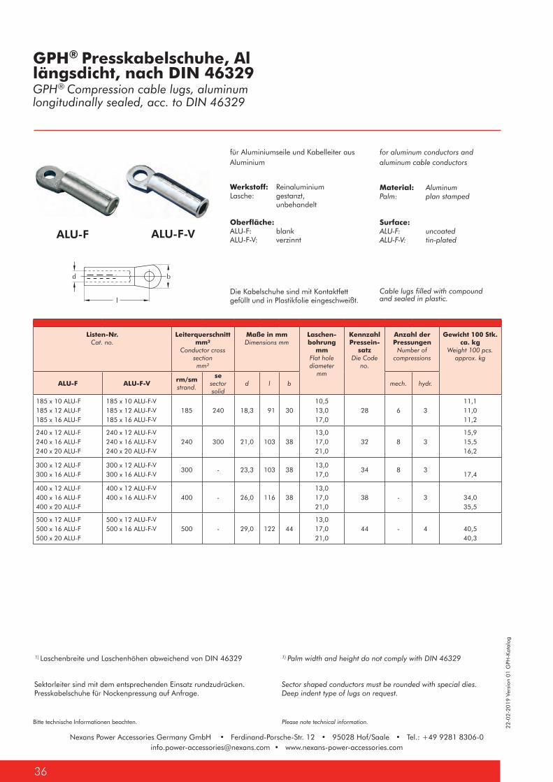
Nexans Power Accessories Germany GmbH • Ferdinand-Porsche-Str. 12 • 95028 Hof/Saale • Tel.: +49 9281 [email protected] • www.nexans-power-accessories.com
22-0
2-20
19 V
ersi
on 0
1 G
PH-K
atal
og
Bitte technische Informationen beachten. Please note technical information.
Nexans Power Accessories Germany GmbH • Ferdinand-Porsche-Str. 12 • 95028 Hof/Saale • Tel.: +49 9281 [email protected] • www.nexans-power-accessories.com
36
Sektorleiter sind mit dem entsprechenden Einsatz rundzudrücken.Presskabelschuhe für Nockenpressung auf Anfrage.
Sector shaped conductors must be rounded with special dies.Deep indent type of lugs on request.
GPH® Presskabelschuhe, Allängsdicht, nach DIN 46329GPH® Compression cable lugs, aluminumlongitudinally sealed, acc. to DIN 46329
ALU-F ALU-F-V
for aluminum conductors and aluminum cable conductors
Material: AluminumPalm: plan stamped
Surface: ALU-F: uncoatedALU-F-V: tin-plated
Cable lugs filled with compound and sealed in plastic.
für Aluminiumseile und Kabelleiter aus Aluminium
Werkstoff: ReinaluminiumLasche: gestanzt, unbehandelt
Oberfläche: ALU-F: blankALU-F-V: verzinnt
Die Kabelschuhe sind mit Kontaktfett gefüllt und in Plastikfolie eingeschweißt.
Listen-Nr.Cat. no.
Leiterquerschnitt mm²
Conductor cross section mm²
Maße in mmDimensions mm
Laschen-bohrung
mmFlat hole diameter
mm
Kennzahl Pressein-
satzDie Code
no.
Anzahl der Pressungen
Number of compressions
Gewicht 100 Stk. ca. kg
Weight 100 pcs. approx. kg
ALU-F ALU-F-V rm/smstrand.
sesector solid
d l b mech. hydr.
185 x 10 ALU-F185 x 12 ALU-F185 x 16 ALU-F
185 x 10 ALU-F-V185 x 12 ALU-F-V185 x 16 ALU-F-V
185 240 18,3 91 3010,513,017,0
28 6 311,111,011,2
240 x 12 ALU-F240 x 16 ALU-F240 x 20 ALU-F
240 x 12 ALU-F-V240 x 16 ALU-F-V240 x 20 ALU-F-V
240 300 21,0 103 3813,017,021,0
32 8 315,915,516,2
300 x 12 ALU-F300 x 16 ALU-F
300 x 12 ALU-F-V300 x 16 ALU-F-V
300 - 23,3 103 3813,017,0
34 8 317,4
400 x 12 ALU-F400 x 16 ALU-F400 x 20 ALU-F
400 x 12 ALU-F-V400 x 16 ALU-F-V 400 - 26,0 116 38
13,017,021,0
38 - 3 34,035,5
500 x 12 ALU-F 500 x 16 ALU-F500 x 20 ALU-F
500 x 12 ALU-F-V500 x 16 ALU-F-V 500 - 29,0 122 44
13,017,021,0
44 - 4 40,540,3
1) Laschenbreite und Laschenhöhen abweichend von DIN 46329 1) Palm width and height do not comply with DIN 46329

22-0
2-20
19 V
ersi
on 0
1 G
PH-K
atal
og
37
Bitte technische Informationen beachten. Please note technical information.
Nexans Power Accessories Germany GmbH • Ferdinand-Porsche-Str. 12 • 95028 Hof/Saale • Tel.: +49 9281 [email protected] • www.nexans-power-accessories.com
Cupal-Scheibe, Al/Cu Cupal discaluminum/copper
aluminum sheet, copper-plated on one side; the plating is 30% of the total thickness of the sheet
Material: Aluminum / Copper
einseitig mit Kupfer plattiertes Aluminiumblech mit einer Kupferauflage von 30% der Gesamtblechstärke
Werkstoff: Aluminium / Kupfer
Listen-Nr.Cat. no.
für Schraube for bolt
Maße in mmDimensions mm
Cupal-Scheibe d1 d2 s
M8 Cupalscheibe M8 18 8,5 1
M10 Cupalscheibe M10 22 11,0 2
M12 Cupalscheibe M12 28 13,0 2
M14 Cupalscheibe M14 28 15,0 2
M16 Cupalscheibe M16 35 17,0 2
M20 Cupalscheibe M20 36 21,0 1
Pressabzweigklemmen, Cu, H-Form Copper compression tap connectors, H-shape
KU-H
for copper conductors
Material: Copper
Surface: KU-H: uncoatedKU-H-V: tin-plated
für Kupferleiter
Werkstoff: Kupfer Oberfläche: KU-H: blankKU-H-V: verzinnt
Listen-Nr.Cat. no.
Querschnitt mm² Hauptleiter
Cross section mm² Main conductor
Abzweig Tap Conductor
Durchmesser mm HauptleiterDiameter mm
Main conductor
AbzweigTap Conductor
KU-H KU-H-V
2 x 50 KU-H 2 x 50 KU-H-V 50 50 9,0 9,0
2 x 70 KU-H 2 x 70 KU-H-V 70 70 10,5 10,5
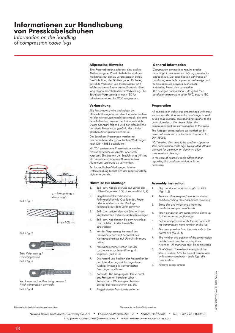
22-0
2-20
19 V
ersi
on 0
1 G
PH-K
atal
og
Bitte technische Informationen beachten. Please note technical information.
Nexans Power Accessories Germany GmbH • Ferdinand-Porsche-Str. 12 • 95028 Hof/Saale • Tel.: +49 9281 [email protected] • www.nexans-power-accessories.com
38
Allgemeine HinweiseEine Pressverbindung erfordert eine exakte Abstimmung der Presskabelschuhe und des Werkzeugs auf den zu verpressenden Leiter. Die Einhaltung der DIN-Vorgaben für Leiter, gewählte Verbinder und Presseinsätze führt erfahrungsgemäß zum besten Ergebnis: Einer langlebigen, hochbelastbaren Verbindung. Die Sechskant-Verpressung ist nach IEC für Leitertemperaturen bis 90°C vorgesehen.
VorbereitungAlle Presskabelschuhe sind neben der Querschnittsangabe und dem Herstellerzeichen mit der Werkzeugkennzahl gestempelt, die etwa dem Außendurchmesser der Hülse entspricht. Dieser Kennzahl folgend wird der erforderliche normierte Presseinsatz gewählt, der mit der gleichen Ziffer gekennzeichnet ist.
Die Sechskant-Pressungen werden mit mechanischen oder hydraulischen Werkzeugen nach DIN 48083 ausgeführt.
Mit "Cu" gestempelte Presseinsätze werden Presskabelschuhe aus Kupfer oder Stahl verpresst. Einsätze mit der Bezeichnung "AI" sind für Presskabelschuhe aus Aluminium bzw. Aluminium-Legierung zu verwenden.
Bei hydraulischen Werkzeugen ist eine Unterscheidung hinsichtlich der Leiterwerkstoffe nicht erforderlich.
Hinweise zur Montage1. Seil- bzw. Kabelisolierung auf Länge der
Hülsenlänge (a+10 %) absetzen (Bild 1, 2)
2. Gegebenenfalls vorhandene Füllmaterialien wie Quellbänder, Puder oder Ähnliches vor der Montage vollständig aus dem Leiter entfernen
3. Seil- bzw. Leiterenden von Schmutz- und Oxydschichten mittels Drahtbürste reinigen
4. Seil- bzw. Kabelenden bis zum Anschlag/bzw. Sichtloch in der Presshülse einschieben
5. Vor der Verpressung Kennzahl des Presskabelschuhs mit Kennzahl des Werkzeugeinsatzes auf Übereinstimmung prüfen
6. Presskabelschuhe werden von der Laschenseite zur Leiteröffnung hin verpresst. (Bild 3, 4)
7. Die Anzahl und Position der Pressstellen ist durch Markierungsstriche angedeutet. Wichtig: Immer alle vormarkierten Pressungen ausführen.
8. Kontrolle: Die Längung der Hülse durch das Pressen mit korrekter Leiter - Kabelschuh - Werkzeugkombination beträgt bei Kabelschuhen ca. 5%.
9. Ausgetretenen Presszusatz entfernen
General Information Compression connections require precise matching of compression cable lugs, conductor and tool size. DIN specification adherence of conductor, selected compression cable lugs and compression die provides best results: A durable, heavy duty connection. The hexagon compression is designed for a conductor temperature up to 90°C, acc. to IEC.
a = Hülsenlänge / sleeve length
Bild / fig. 1
Bild / fig. 2
Erste Verpressung /First compression
Von innen nach außen fertig pressen /Finish compression outwards
a+10%
Informationen zur Handhabung von PresskabelschuhenInformation on the handlingof compression cable lugs
Bild / fig. 3
Bild / fig. 4
Assembly instruction:1. Strip conductor to sleeve length a+10%
(fig. 1, 2)
2. Remove all tapes/yarn/powder or similar conductor filling materials before mounting
3. Erase dirt and oxide layers from the conductor using a metal brush
4. Insert conductor into compression sleeve up to the stop or inspection hole
5. Before compression verify the die code with the compression mark number on the lug
6. Start compression from the palm side to the barrel end (fig. 3, 4)
7. The number and position of the compression points is indicated by marking lines. Attention: All markings must be compressed
8. Final Check: The extension length of the sleeve is about 5 % by correct compression with correct conductor - cable lug - die - combination
9. Remove excess grease
Preparation
All compression cable lugs are stamped with cross section specification, manufacturer's logo as well as die code number, corresponding roughly to the outer diameter of the sleeve. Select the compression tool die corresponding to this code.
The hexagon compressions are carried out by means of mechanical or hydraulic tools acc. to DIN 48083.
“Cu” marked dies have to be used for copper or steel compression cable lugs. Designated "Al" dies are used for aluminum or aluminum alloy compression cable lugs.
In the case of hydraulic tools differentiation regarding the conductor materials is not necessary.
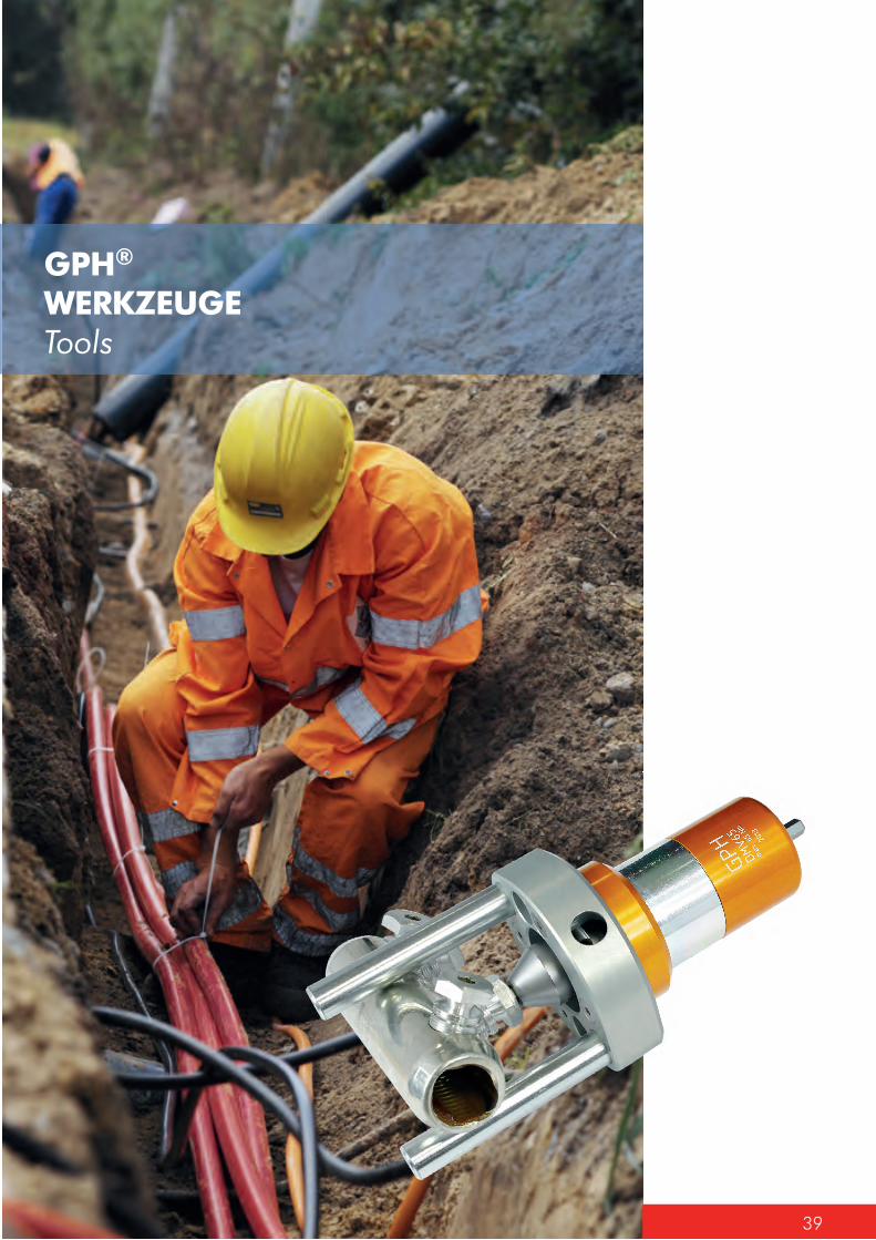
39
GPH® WERKZEUGETools
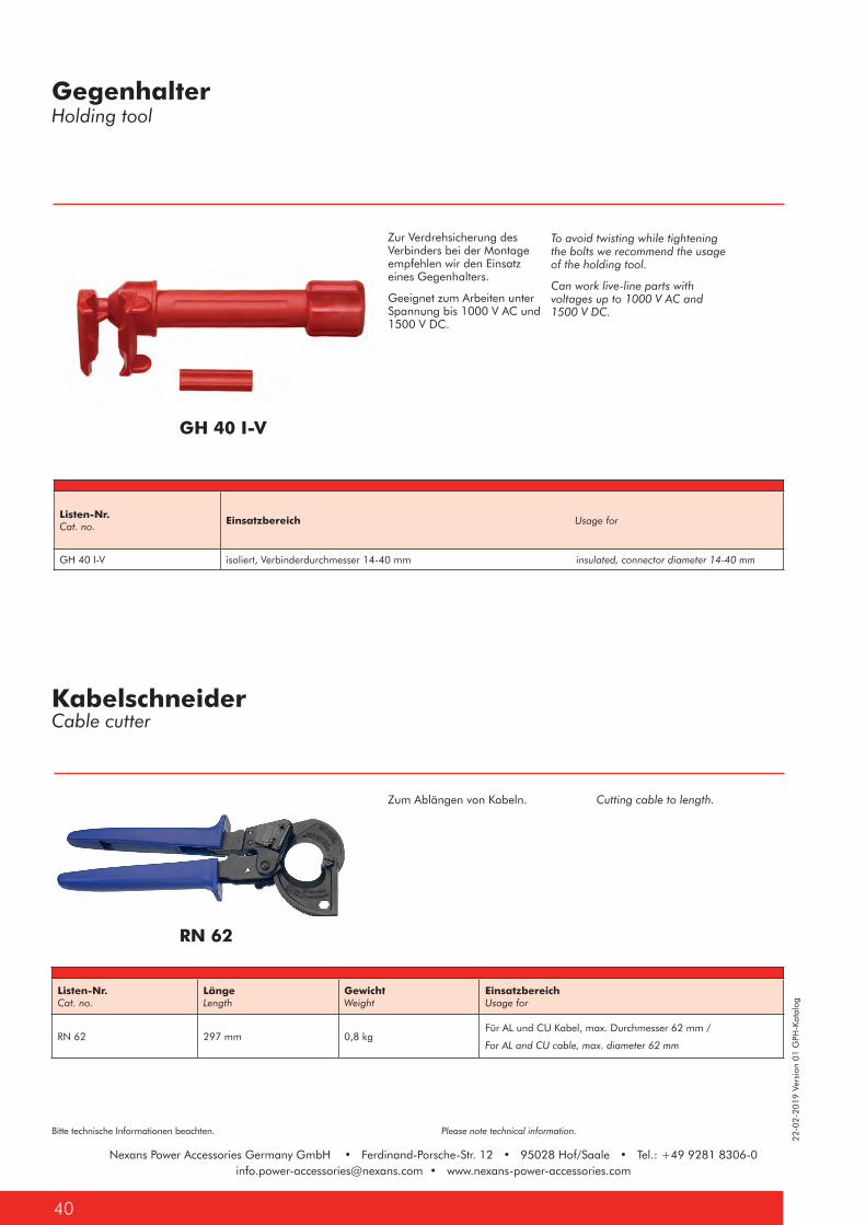
Nexans Power Accessories Germany GmbH • Ferdinand-Porsche-Str. 12 • 95028 Hof/Saale • Tel.: +49 9281 [email protected] • www.nexans-power-accessories.com
22-0
2-20
19 V
ersi
on 0
1 G
PH-K
atal
og
Bitte technische Informationen beachten. Please note technical information.
Nexans Power Accessories Germany GmbH • Ferdinand-Porsche-Str. 12 • 95028 Hof/Saale • Tel.: +49 9281 [email protected] • www.nexans-power-accessories.com
40
To avoid twisting while tightening the bolts we recommend the usage of the holding tool.
Can work live-line parts with voltages up to 1000 V AC and 1500 V DC.
Zur Verdrehsicherung des Verbinders bei der Montage empfehlen wir den Einsatz eines Gegenhalters.
Geeignet zum Arbeiten unter Spannung bis 1000 V AC und 1500 V DC.
Zum Ablängen von Kabeln. Cutting cable to length.
GH 40 I-V
GegenhalterHolding tool
KabelschneiderCable cutter
Listen-Nr.Cat. no.
Einsatzbereich Usage for
GH 40 I-V isoliert, Verbinderdurchmesser 14-40 mm insulated, connector diameter 14-40 mm
Listen-Nr.Cat. no.
LängeLength
GewichtWeight
EinsatzbereichUsage for
RN 62 297 mm 0,8 kgFür AL und CU Kabel, max. Durchmesser 62 mm /
For AL and CU cable, max. diameter 62 mm
RN 62
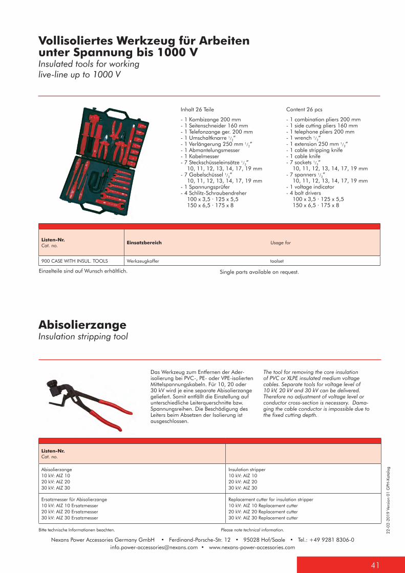
22-0
2-20
19 V
ersi
on 0
1 G
PH-K
atal
og
41
Bitte technische Informationen beachten. Please note technical information.
Nexans Power Accessories Germany GmbH • Ferdinand-Porsche-Str. 12 • 95028 Hof/Saale • Tel.: +49 9281 [email protected] • www.nexans-power-accessories.com
Content 26 pcs
- 1 combination pliers 200 mm - 1 side cutting pliers 160 mm - 1 telephone pliers 200 mm - 1 wrench 1/2” - 1 extension 250 mm 1/2” - 1 cable stripping knife - 1 cable knife - 7 sockets 1/2” 10, 11, 12, 13, 14, 17, 19 mm - 7 spanners 1/2” 10, 11, 12, 13, 14, 17, 19 mm - 1 voltage indicator - 4 bolt drivers 100 x 3,5 · 125 x 5,5 150 x 6,5 · 175 x 8
The tool for removing the core insulation of PVC or XLPE insulated medium voltage cables. Separate tools for voltage level of 10 kV, 20 kV and 30 kV can be delivered. Therefore no adjustment of voltage level or conductor cross-section is necessary. Dama-ging the cable conductor is impossible due to the fixed cutting depth.
Inhalt 26 Teile
- 1 Kombizange 200 mm - 1 Seitenschneider 160 mm - 1 Telefonzange ger. 200 mm - 1 Umschaltknarre 1/2” - 1 Verlängerung 250 mm 1/2” - 1 Abmantelungsmesser - 1 Kabelmesser - 7 Steckschüsseleinsätze 1/2” 10, 11, 12, 13, 14, 17, 19 mm - 7 Gabelschüssel 1/2” 10, 11, 12, 13, 14, 17, 19 mm - 1 Spannungsprüfer - 4 Schlitz-Schraubendreher 100 x 3,5 · 125 x 5,5 150 x 6,5 · 175 x 8
Das Werkzeug zum Entfernen der Ader-isolierung bei PVC-, PE- oder VPE-isolierten Mittelspannungskabeln. Für 10, 20 oder 30 kV wird je eine separate Abisolierzange geliefert. Somit entfällt die Einstellung auf unterschiedliche Leiterquerschnitte bzw. Spannungsreihen. Die Beschädigung des Leiters beim Absetzen der Isolierung ist ausgeschlossen.
Einzelteile sind auf Wunsch erhältlich. Single parts available on request.
AbisolierzangeInsulation stripping tool
Vollisoliertes Werkzeug für Arbeiten unter Spannung bis 1000 VInsulated tools for working live-line up to 1000 V
Listen-Nr.Cat. no.
Einsatzbereich Usage for
900 CASE WITH INSUL. TOOLS Werkzeugkoffer toolset
Listen-Nr.Cat. no.
Abisolierzange10 kV: AIZ 1020 kV: AIZ 2030 kV: AIZ 30
Insulation stripper10 kV: AIZ 1020 kV: AIZ 2030 kV: AIZ 30
Ersatzmesser für Abisolierzange10 kV: AIZ 10 Ersatzmesser20 kV: AIZ 20 Ersatzmesser30 kV: AIZ 30 Ersatzmesser
Replacement cutter for insulation stripper10 kV: AIZ 10 Replacement cutter20 kV: AIZ 20 Replacement cutter30 kV: AIZ 30 Replacement cutter
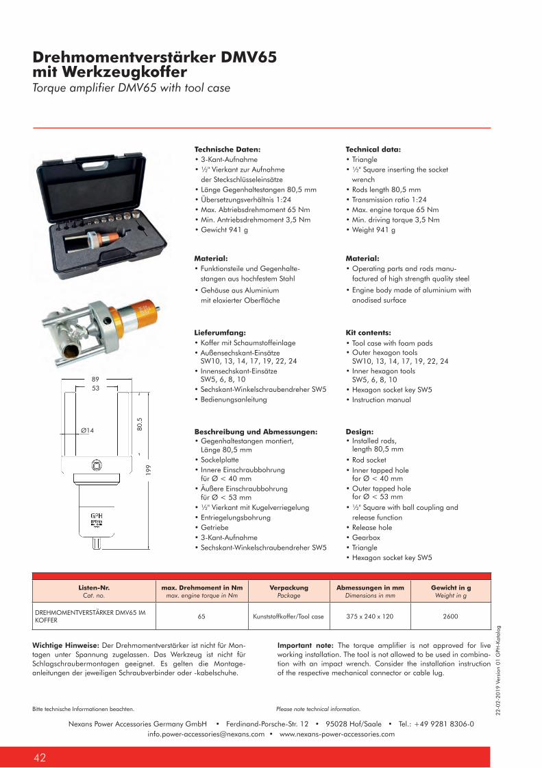
Nexans Power Accessories Germany GmbH • Ferdinand-Porsche-Str. 12 • 95028 Hof/Saale • Tel.: +49 9281 [email protected] • www.nexans-power-accessories.com
22-0
2-20
19 V
ersi
on 0
1 G
PH-K
atal
og
Bitte technische Informationen beachten. Please note technical information.
Nexans Power Accessories Germany GmbH • Ferdinand-Porsche-Str. 12 • 95028 Hof/Saale • Tel.: +49 9281 [email protected] • www.nexans-power-accessories.com
42
Drehmomentverstärker DMV65 mit WerkzeugkofferTorque amplifier DMV65 with tool case
Technische Daten:• 3-Kant-Aufnahme• ½" Vierkant zur Aufnahme der Steckschlüsseleinsätze• Länge Gegenhaltestangen 80,5 mm• Übersetzungsverhältnis 1:24• Max. Abtriebsdrehmoment 65 Nm• Min. Antriebsdrehmoment 3,5 Nm• Gewicht 941 g
Listen-Nr.Cat. no.
max. Drehmoment in Nmmax. engine torque in Nm
VerpackungPackage
Abmessungen in mmDimensions in mm
Gewicht in gWeight in g
DREHMOMENTVERSTÄRKER DMV65 IM KOFFER
65 Kunststoffkoffer/Tool case 375 x 240 x 120 2600
Wichtige Hinweise: Der Drehmomentverstärker ist nicht für Mon-tagen unter Spannung zugelassen. Das Werkzeug ist nicht für Schlagschraubermontagen geeignet. Es gelten die Montage-anleitungen der jeweiligen Schraubverbinder oder -kabelschuhe.
Important note: The torque amplifier is not approved for live working installation. The tool is not allowed to be used in combina-tion with an impact wrench. Consider the installation instruction of the respective mechanical connector or cable lug.
PRODUKTDATENBLATT Mod. Nr.: DMV65
Drehmomentverstärker DMV65Art. Nr.: xxxxxx
Datum: 45/13 DAbmessungen in mm
Normen :
-
Anwendung:
- Der Drehmomentverstärker DMV65 ist geeignet zum schonenden Abreisen von Schraubverbindern mit handelsüblichen Akkuschraubern.
Materialien:
- Funktionsteile aus hochlegiertem Stahl.- Gehäuse aus Aluminium mit eloxierter Oberfläche.- Scheibe aus Aluminium mit eloxierter Oberfläche.- Stange aus hochlegiertem Stahl mit verzinkter Oberfläche.
Technische Eigenschaften
- 3-Kant Aufnahme zur Aufnahme von handelsüblichen Akkuschrauber-Dreibackenfutter.- ½“ Vierkant zum Aufnehmen von handelsüblichen Steckschlüsseleinsätzen und Inbus Einsätzen.- Übersetzungsverhältnis 1:24- Länge Stange: 80,5mm- Maximales Abtriebsdrehmoment von 65Nm- Minimales Antriebsdrehmoment von 3,5Nm- Antrieb bricht bei Fallhöhe 1m auf Betonboden nicht ab, fest eingeschraubte Gabeln verbiegen nicht- Einseitiges Anliegen an Verbinderkörper und 65Nm Anzugsmoment: Gabeln verbiegen nicht nach.- Keine Ausfälle durch normale Verschmutzungen bei regulären Gebrauch in Baustellenumgebung (keine grobe
Verschmutzung durch Sand, etc.!!!)- Schutzart: IP54- ACHTUNG: Nicht für Schlagschrauber geeignet!!!
Beschriftung:
- Logo: “ “- Modellnummer: “DMV65“- Max. Drehmoment: “max. 65Nm“- Baujahr: “2013“
Lieferumfang: • Koffer mit Schaumstoffeinlage• Außensechskant-Einsätze SW10, 13, 14, 17, 19, 22, 24• Innensechskant-Einsätze SW5, 6, 8, 10• Sechskant-Winkelschraubendreher SW5• Bedienungsanleitung
Kit contents: • Tool case with foam pads
Technical data:• Triangle• ½" Square inserting the socket wrench• Rods length 80,5 mm• Transmission ratio 1:24• Max. engine torque 65 Nm• Min. driving torque 3,5 Nm• Weight 941 g
Material:• Operating parts and rods manu- factured of high strength quality steel
Material:• Funktionsteile und Gegenhalte- stangen aus hochfestem Stahl
• Gehäuse aus Aluminium mit eloxierter Oberfläche
• Engine body made of aluminium with anodised surface
• Outer hexagon tools SW10, 13, 14, 17, 19, 22, 24
• Hexagon socket key SW5• Instruction manual
Beschreibung und Abmessungen:• Gegenhaltestangen montiert, Länge 80,5 mm • Sockelplatte• Innere Einschraubbohrung für Ø < 40 mm• Äußere Einschraubbohrung für Ø < 53 mm• ½" Vierkant mit Kugelverriegelung• Entriegelungsbohrung• Getriebe• 3-Kant-Aufnahme• Sechskant-Winkelschraubendreher SW5
Design:
• ½" Square with ball coupling and release function• Release hole• Gearbox• Triangle• Hexagon socket key SW5
• Outer tapped hole for Ø < 53 mm
• Inner tapped hole for Ø < 40 mm
• Installed rods, length 80,5 mm• Rod socket
• Inner hexagon tools SW5, 6, 8, 10
Ø14
8953
80.5
199

22-0
2-20
19 V
ersi
on 0
1 G
PH-K
atal
og
43
Bitte technische Informationen beachten. Please note technical information.
Nexans Power Accessories Germany GmbH • Ferdinand-Porsche-Str. 12 • 95028 Hof/Saale • Tel.: +49 9281 [email protected] • www.nexans-power-accessories.com
Drehmomentverstärker DMV65 potentialgetrennt, mit WerkzeugkofferTorque amplifier DMV65, isolated, with tool case
Technische Daten: • 3-Kant-Aufnahme • ½" Vierkant zur Aufnahme der Steckschlüsseleinsätze • Länge Gegenhaltestangen 81 mm • Übersetzungsverhältnis 1:24 • Max. Abtriebsdrehmoment 65 Nm • Min. Antriebsdrehmoment 3,5 Nm • Gewicht 1380 g
Listen-Nr.Cat. no.
max. Drehmoment in Nmmax. engine torque in Nm
VerpackungPackage
Abmessungen in mmDimensions in mm
Gewicht in gWeight in g
DREHMOMENTVERSTÄRKER POTENTIALGETRENNT DMV65
65 Kunststoffkoffer/Tool case 375 x 240 x 120 3000
Wichtige Hinweise: Laut Herstellereignungsprüfung in Anlehnung an EN 60900, ist die Potentialtrennung zwischen Monteur und Verbinder durch dieses Werkzeug gewährleistet, ersetzt jedoch nicht das Tragen der Persönlichen Schutzausrüstung (PSA). Der Kontakt zu benachbarten Verbindern ist zu vermeiden. Das Werkzeug ist nicht für Schlagschraubermontagen geeignet. Es gelten die Montage- anleitungen der jeweiligen Schraubverbinder oder -kabelschuhe.
Important note: According to manufacturer self-test referring to EN 60900, the electrical isolation between installer and connector is given by the tool. Nevertheless, wearing of personal protective equipment (PPE) is mandatory. The contact with other connectors nearby has to be avoided. The tool is not allowed to be used in combination with an impact wrench. Consider the installation instruction of the respective mechanical connector or cable lug.
Technical data: • Triangle • ½" Square inserting the socket wrench • Rods length 81 mm • Transmission ratio 1:24 • Max. engine torque 65 Nm • Min. driving torque 3,5 Nm • Weight 1380 g
Beschreibung und Abmessungen:• Gegenhaltestangen montiert, isoliert, Länge 81 mm • Abdeckplatte• Innere Einschraubbohrung für Ø < 36 mm• Äußere Einschraubbohrung für Ø < 48 mm• Getriebe, isoliert• 3-Kant-Aufnahme• Sechskant-Winkelschraubendreher SW5
Design:
• Gearbox, insulated• Triangle • Hexagon socket key SW5
• Outer tapped hole
for Ø < 48 mm
• Inner tapped hole for Ø < 36 mm
• Installed rods, insulated length 81 mm• Cover plate
Lieferumfang: • Koffer mit Schaumstoffeinlage• Außensechskant-Einsätze SW10, 13, 14, 17, 19, 22, 24• Innensechskant-Einsätze SW5, 6, 8, 10• Sechskant-Winkelschraubendreher SW5• Bedienungsanleitung
Kit contents: • Tool case with foam pads • Outer hexagon tools SW10, 13, 14, 17, 19, 22, 24
• Hexagon socket key SW5 • Instruction manual
• Inner hexagon tools SW5, 6, 8, 10
Material:Material:• Funktionsteile und Gegenhaltestangen aus hochfestem Stahl mit kunststoff- ummantelten Oberflächen (Polyamid PA)
• Operating parts and rods manufactured of high strength quality steel with plastic- covered surfaces (Polyamide PA)
• Engine body made of aluminum with plastic cover (Polyoxymethylene POM)
• Aluminiumgehäuse mit Kunststoff- abdeckung (Polyoxymethylen POM)
51
8123
9
Ø16
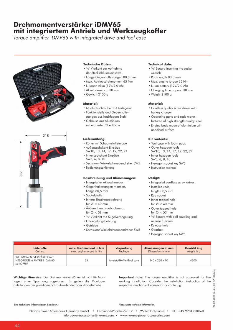
Nexans Power Accessories Germany GmbH • Ferdinand-Porsche-Str. 12 • 95028 Hof/Saale • Tel.: +49 9281 [email protected] • www.nexans-power-accessories.com
22-0
2-20
19 V
ersi
on 0
1 G
PH-K
atal
og
Bitte technische Informationen beachten. Please note technical information.
Nexans Power Accessories Germany GmbH • Ferdinand-Porsche-Str. 12 • 95028 Hof/Saale • Tel.: +49 9281 [email protected] • www.nexans-power-accessories.com
44
Drehmomentverstärker iDMV65 mit integriertem Antrieb und WerkzeugkofferTorque amplifier iDMV65 with integrated drive and tool case
Technische Daten: • ½" Vierkant zur Aufnahme der Steckschlüsseleinsätze • Länge Gegenhaltestangen 80,5 mm • Max. Abtriebsdrehmoment 65 Nm • Li-Ionen Akku (12V/2,0 Ah) • Akkuladezeit ca. 30 min • Gewicht 2100 g
Listen-Nr.Cat. no.
max. Drehmoment in Nmmax. engine torque in Nm
VerpackungPackage
Abmessungen in mmDimensions in mm
Gewicht in gWeight in g
DREHMOMENTVERSTÄRKER MIT INTEGRIERTEM ANTRIEB iDMV65IM KOFFER
65 Kunststoffkoffer/Tool case 340 x 230 x 70 4200
Wichtige Hinweise: Der Drehmomentverstärker ist nicht für Mon-tagen unter Spannung zugelassen. Es gelten die Montage-anleitungen der jeweiligen Schraubverbinder oder -kabelschuhe.
Important note: The torque amplifier is not approved for live working installation. Consider the installation instruction of the respective mechanical connector or cable lug.
Lieferumfang: • Koffer mit Schaumstoffeinlage• Außensechskant-Einsätze SW10, 13, 14, 17, 19, 22, 24• Innensechskant-Einsätze SW5, 6, 8, 10• Sechskant-Winkelschraubendreher SW5• Bedienungsanleitung
Kit contents: • Tool case with foam pads
Technical data: • ½" Square inserting the socket wrench • Rods length 80,5 mm • Max. engine torque 65 Nm • Li-Ion battery (12V/2,0 Ah) • Charging time approx. 30 min • Weight 2100 g
Material: • Cordless quality screw driver with battery charger • Operating parts and rods manu- factured of high strength quality steel
Material: • Qualitätsschrauber mit Ladegerät • Funktionsteile und Gegenhalte- stangen aus hochfestem Stahl • Gehäuse aus Aluminium mit eloxierter Oberfläche • Engine body made of aluminium with
anodised surface
• Outer hexagon tools SW10, 13, 14, 17, 19, 22, 24
• Hexagon socket key SW5 • Instruction manual
Beschreibung und Abmessungen:• Intergrierter Akkuschrauber• Gegenhaltestangen montiert, Länge 80,5 mm• Sockelplatte• Innere Einschraubbohrung für Ø < 40 mm• Äußere Einschraubbohrung für Ø < 53 mm• ½" Vierkant mit Kugelverriegelung• Entriegelungsbohrung• Getriebe• Sechskant-Winkelschraubendreher SW5
Design:
• ½" Square with ball coupling and release function• Release hole• Gearbox • Hexagon socket key SW5
• Outer tapped hole for Ø < 53 mm
• Inner tapped hole for Ø < 40 mm
• Integrated cordless screw driver
• Rod socket
• Inner hexagon tools SW5, 6, 8, 10
• Installed rods, length 80,5 mm
218
336
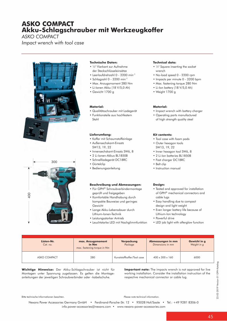
22-0
2-20
19 V
ersi
on 0
1 G
PH-K
atal
og
45
Bitte technische Informationen beachten. Please note technical information.
Nexans Power Accessories Germany GmbH • Ferdinand-Porsche-Str. 12 • 95028 Hof/Saale • Tel.: +49 9281 [email protected] • www.nexans-power-accessories.com
ASKO COMPACT Akku-Schlagschrauber mit WerkzeugkofferASKO COMPACT Impact wrench with tool case
Technische Daten:• ½" Vierkant zur Aufnahme der Steckschlüsseleinsätze• Leerlaufdrehzahl 0 - 2200 min-1
• Schlagzahl 0 - 3200 min-1
• Max. Anzugsmoment 280 Nm• Li-Ionen Akku (18 V/5,0 Ah)• Gewicht 1700 g
Listen-Nr.Cat. no.
max. Anzugsmoment in Nm
max. fastening torque in Nm
VerpackungPackage
Abmessungen in mmDimensions in mm
Gewicht in gWeight in g
ASKO COMPACT 280 Kunststoffkoffer/Tool case 400 x 300 x 160 6000
Wichtige Hinweise: Der Akku-Schlagschrauber ist nicht für Montagen unter Spannung zugelassen. Es gelten die Montage-anleitungen der jeweiligen Schraubverbinder oder -kabelschuhe.
Important note: The impacts wrench is not approved for liveworking installation. Consider the installation instruction of therespective mechanical connector or cable lug.
Lieferumfang: • Koffer mit Schaumstoffeinlage• Außensechskant-Einsatz SW13, 19, 22• Innensechskant-Einsatz SW6, 8• 2 Li-Ionen-Akkus BL1850B• Schnellladegerät DC18RC• Gürtelclip• Bedienungsanleitung
Kit contents: • Tool case with foam pads• Outer hexagon tools SW13, 19, 22• Inner hexagon tool SW6, 8• 2 Li-Ion batteries BL1850B• Fast charger DC18RC• Belt clip• Instruction manual
Technical data:• ½" Square inserting the socket wrench• No-load speed 0 - 2200 rpm• Impacts per minute 0 - 3200 bpm• Max. fastening torque 280 Nm• Li-Ion battery (18 V/5,0 Ah)• Weight 1700 g
Material:• Impact wrench with battery charger• Operating parts manufactured of high strength quality steel
Material:• Qualitätsschrauber mit Ladegerät• Funktionsteile aus hochfestem Stahl
Beschreibung und Abmessungen:• Für GPH® Schraubverbindermontage geprüft und freigegeben• Komfortable Handhabung durch kompakte Bauweise und geringes Gewicht• Lange Akku-Lebensdauer durch Lithium-Ionen-Technik• Leistungsstarker Antrieb• Leuchtstarke LED mit Nachglimmfunktion
Design:• Tested and approved for installation of GPH® mechanical connectors and cable lugs• Easy handling due to compact design and light weight• Even longer battery life because of Lithium-Ion technology• Powerful drive• LED job light with afterglow function
300
400
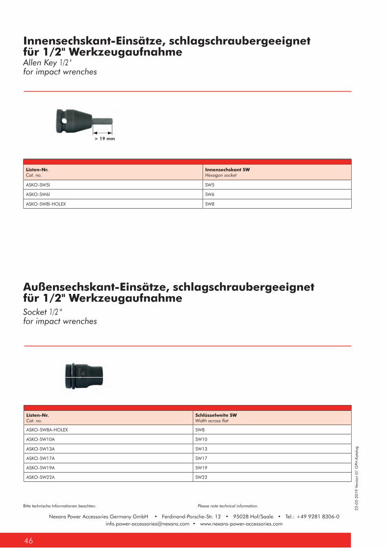
Nexans Power Accessories Germany GmbH • Ferdinand-Porsche-Str. 12 • 95028 Hof/Saale • Tel.: +49 9281 [email protected] • www.nexans-power-accessories.com
22-0
2-20
19 V
ersi
on 0
1 G
PH-K
atal
og
Bitte technische Informationen beachten. Please note technical information.
Nexans Power Accessories Germany GmbH • Ferdinand-Porsche-Str. 12 • 95028 Hof/Saale • Tel.: +49 9281 [email protected] • www.nexans-power-accessories.com
46
> 19 mm
Innensechskant-Einsätze, schlagschraubergeeignet für 1/2" Werkzeugaufnahme
Außensechskant-Einsätze, schlagschraubergeeignet für 1/2" Werkzeugaufnahme
Allen Key 1/2 "for impact wrenches
Socket 1/2 "for impact wrenches
Listen-Nr.Cat. no.
Innensechskant SWHexagon socket
ASKO-SW5l SW5
ASKO-SW6l SW6
ASKO-SW8l-HOLEX SW8
Listen-Nr.Cat. no.
Schlüsselweite SWWidth across flat
ASKO-SW8A-HOLEX SW8
ASKO-SW10A SW10
ASKO-SW13A SW13
ASKO-SW17A SW17
ASKO-SW19A SW19
ASKO-SW22A SW22
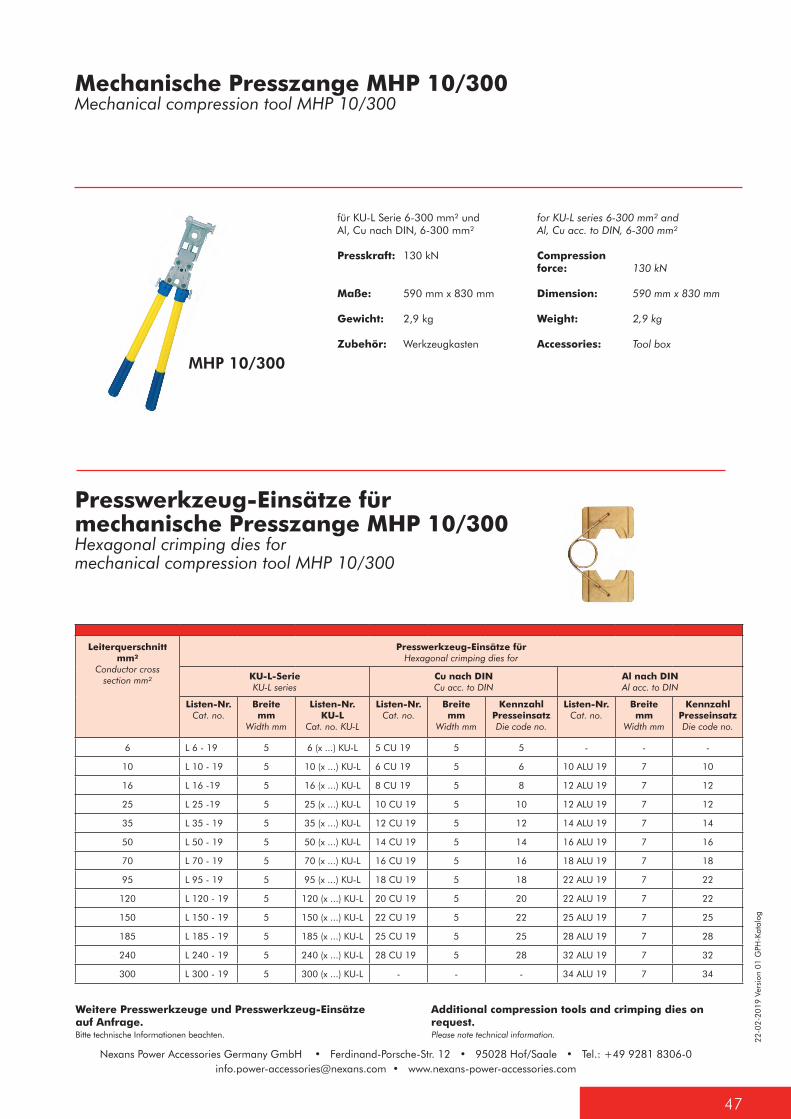
22-0
2-20
19 V
ersi
on 0
1 G
PH-K
atal
og
47
Bitte technische Informationen beachten. Please note technical information.
Nexans Power Accessories Germany GmbH • Ferdinand-Porsche-Str. 12 • 95028 Hof/Saale • Tel.: +49 9281 [email protected] • www.nexans-power-accessories.com
MHP 10/300
für KU-L Serie 6-300 mm² und Al, Cu nach DIN, 6-300 mm²
Presskraft: 130 kN
Maße: 590 mm x 830 mm
Gewicht: 2,9 kg
Zubehör: Werkzeugkasten
for KU-L series 6-300 mm² and Al, Cu acc. to DIN, 6-300 mm²
Compression force: 130 kN
Dimension: 590 mm x 830 mm
Weight: 2,9 kg
Accessories: Tool box
Mechanische Presszange MHP 10/300Mechanical compression tool MHP 10/300
Presswerkzeug-Einsätze für mechanische Presszange MHP 10/300Hexagonal crimping dies formechanical compression tool MHP 10/300
Leiterquerschnitt mm²
Conductor cross section mm²
Presswerkzeug-Einsätze fürHexagonal crimping dies for
KU-L-SerieKU-L series
Cu nach DINCu acc. to DIN
Al nach DINAl acc. to DIN
Listen-Nr.Cat. no.
Breite mm
Width mm
Listen-Nr. KU-L
Cat. no. KU-L
Listen-Nr.Cat. no.
Breite mm
Width mm
Kennzahl PresseinsatzDie code no.
Listen-Nr.Cat. no.
Breite mm
Width mm
Kennzahl PresseinsatzDie code no.
6 L 6 - 19 5 6 (x ...) KU-L 5 CU 19 5 5 - - -
10 L 10 - 19 5 10 (x ...) KU-L 6 CU 19 5 6 10 ALU 19 7 10
16 L 16 -19 5 16 (x ...) KU-L 8 CU 19 5 8 12 ALU 19 7 12
25 L 25 -19 5 25 (x ...) KU-L 10 CU 19 5 10 12 ALU 19 7 12
35 L 35 - 19 5 35 (x ...) KU-L 12 CU 19 5 12 14 ALU 19 7 14
50 L 50 - 19 5 50 (x ...) KU-L 14 CU 19 5 14 16 ALU 19 7 16
70 L 70 - 19 5 70 (x ...) KU-L 16 CU 19 5 16 18 ALU 19 7 18
95 L 95 - 19 5 95 (x ...) KU-L 18 CU 19 5 18 22 ALU 19 7 22
120 L 120 - 19 5 120 (x ...) KU-L 20 CU 19 5 20 22 ALU 19 7 22
150 L 150 - 19 5 150 (x ...) KU-L 22 CU 19 5 22 25 ALU 19 7 25
185 L 185 - 19 5 185 (x ...) KU-L 25 CU 19 5 25 28 ALU 19 7 28
240 L 240 - 19 5 240 (x ...) KU-L 28 CU 19 5 28 32 ALU 19 7 32
300 L 300 - 19 5 300 (x ...) KU-L - - - 34 ALU 19 7 34
Weitere Presswerkzeuge und Presswerkzeug-Einsätze auf Anfrage.
Additional compression tools and crimping dies on request.
22-0
2-20
19 V
ersi
on 0
1 G
PH-K
atal
og
Bitte technische Informationen beachten. Please note technical information.
Nexans Power Accessories Germany GmbH • Ferdinand-Porsche-Str. 12 • 95028 Hof/Saale • Tel.: +49 9281 [email protected] • www.nexans-power-accessories.com
48
NotizenNotes

Nexans Power Accessories Germany GmbHFerdinand-Porsche-Str. 1295028 Hof/Saale Tel.: +49 9281 8306-0
info.power-accessories@nexans.comwww.nexans-power-accessories.com
Find out more about Nexans Power Accessories.