Embed Size (px)
Citation preview
Cycling Design GuideOctober 2006
Nottinghamshire County Council Cycling Design Guide 2006 Index
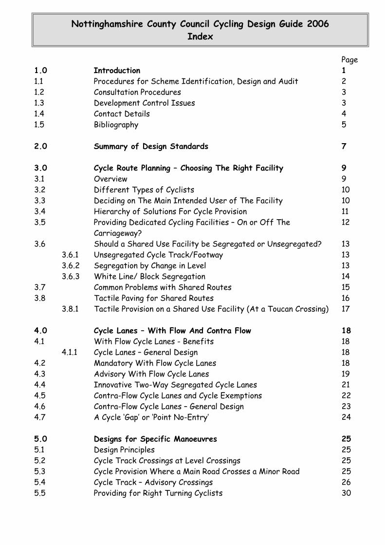
Page 1.0 Introduction 1 1.1 Procedures for Scheme Identification, Design and Audit 2 1.2 Consultation Procedures 3 1.3 Development Control Issues 3 1.4 Contact Details 4 1.5 Bibliography
5
2.0 Summary of Design Standards
7
3.0 Cycle Route Planning – Choosing The Right Facility 9 3.1 Overview 9 3.2 Different Types of Cyclists 10 3.3 Deciding on The Main Intended User of The Facility 10 3.4 Hierarchy of Solutions For Cycle Provision 11 3.5 Providing Dedicated Cycling Facilities – On or Off The
Carriageway? 12
3.6 Should a Shared Use Facility be Segregated or Unsegregated? 13 3.6.1 Unsegregated Cycle Track/Footway 13 3.6.2 Segregation by Change in Level 13 3.6.3 White Line/ Block Segregation 14 3.7 Common Problems with Shared Routes 15 3.8 Tactile Paving for Shared Routes 16 3.8.1 Tactile Provision on a Shared Use Facility (At a Toucan Crossing) 17
4.0 Cycle Lanes – With Flow And Contra Flow 18 4.1 With Flow Cycle Lanes - Benefits 18 4.1.1 Cycle Lanes – General Design 18 4.2 Mandatory With Flow Cycle Lanes 18 4.3 Advisory With Flow Cycle Lanes 19 4.4 Innovative Two-Way Segregated Cycle Lanes 21 4.5 Contra-Flow Cycle Lanes and Cycle Exemptions 22 4.6 Contra-Flow Cycle Lanes – General Design 23 4.7 A Cycle ‘Gap’ or ‘Point No-Entry’ 24
5.0 Designs for Specific Manoeuvres 25 5.1 Design Principles 25 5.2 Cycle Track Crossings at Level Crossings 25 5.3 Cycle Provision Where a Main Road Crosses a Minor Road 25 5.4 Cycle Track – Advisory Crossings 26 5.5 Providing for Right Turning Cyclists 30
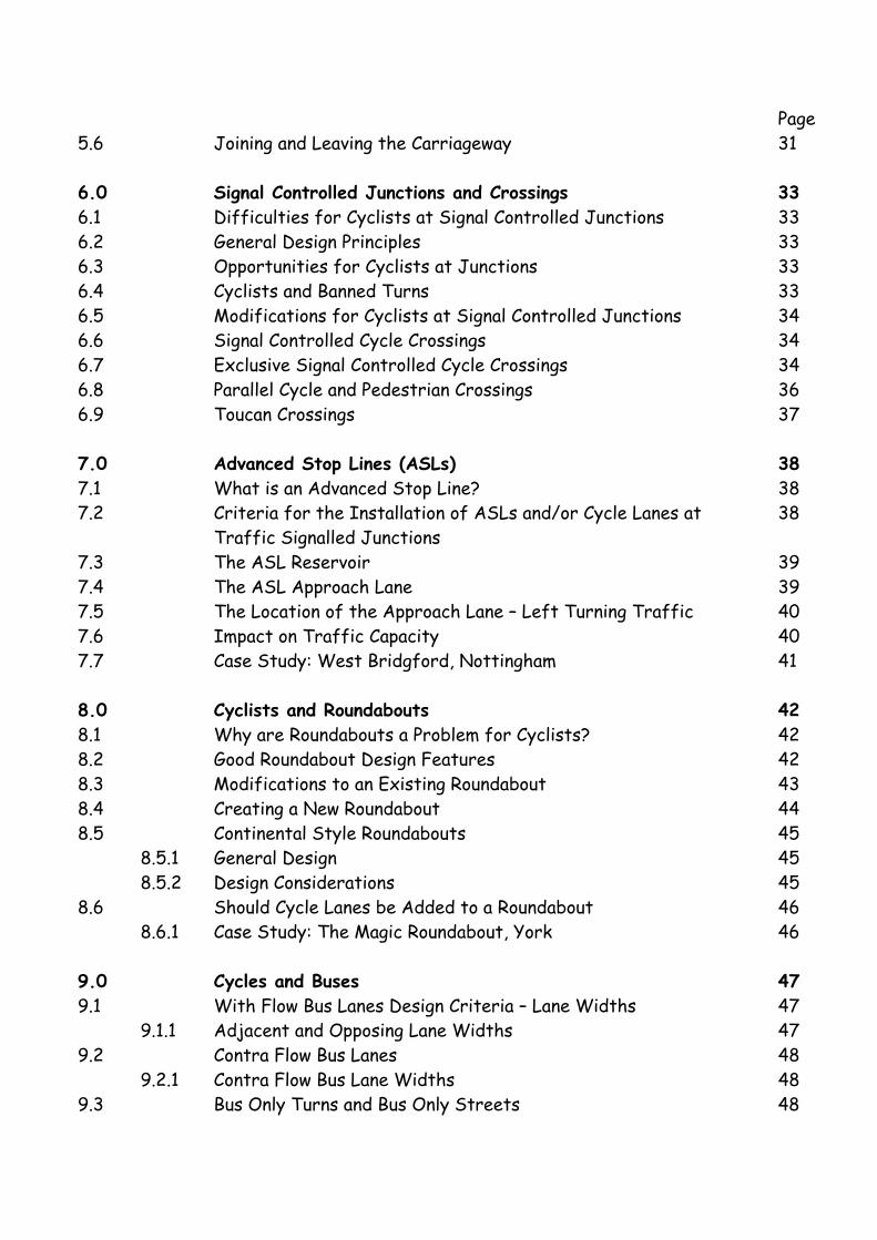
Page 5.6 Joining and Leaving the Carriageway 31 6.0 Signal Controlled Junctions and Crossings 33 6.1 Difficulties for Cyclists at Signal Controlled Junctions 33 6.2 General Design Principles 33 6.3 Opportunities for Cyclists at Junctions 33 6.4 Cyclists and Banned Turns 33 6.5 Modifications for Cyclists at Signal Controlled Junctions 34 6.6 Signal Controlled Cycle Crossings 34 6.7 Exclusive Signal Controlled Cycle Crossings 34 6.8 Parallel Cycle and Pedestrian Crossings 36 6.9 Toucan Crossings 37
7.0 Advanced Stop Lines (ASLs) 38 7.1 What is an Advanced Stop Line? 38 7.2 Criteria for the Installation of ASLs and/or Cycle Lanes at
Traffic Signalled Junctions 38
7.3 The ASL Reservoir 39 7.4 The ASL Approach Lane 39 7.5 The Location of the Approach Lane – Left Turning Traffic 40 7.6 Impact on Traffic Capacity 40 7.7 Case Study: West Bridgford, Nottingham 41
8.0 Cyclists and Roundabouts 42 8.1 Why are Roundabouts a Problem for Cyclists? 42 8.2 Good Roundabout Design Features 42 8.3 Modifications to an Existing Roundabout 43 8.4 Creating a New Roundabout 44 8.5 Continental Style Roundabouts 45 8.5.1 General Design 45 8.5.2 Design Considerations 45 8.6 Should Cycle Lanes be Added to a Roundabout 46 8.6.1 Case Study: The Magic Roundabout, York 46
9.0 Cycles and Buses 47 9.1 With Flow Bus Lanes Design Criteria – Lane Widths 47 9.1.1 Adjacent and Opposing Lane Widths 47 9.2 Contra Flow Bus Lanes 48 9.2.1 Contra Flow Bus Lane Widths 48 9.3 Bus Only Turns and Bus Only Streets 48
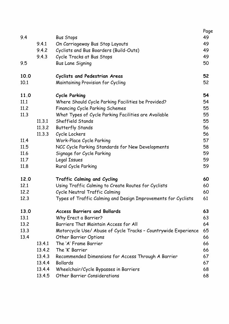
Page 9.4 Bus Stops 49 9.4.1 On Carriageway Bus Stop Layouts 49 9.4.2 Cyclists and Bus Boarders (Build-Outs) 49 9.4.3 Cycle Tracks at Bus Stops 49 9.5 Bus Lane Signing 50
10.0 Cyclists and Pedestrian Areas 52 10.1 Maintaining Provision for Cycling 52
11.0 Cycle Parking 54 11.1 Where Should Cycle Parking Facilities be Provided? 54 11.2 Financing Cycle Parking Schemes 55 11.3 What Types of Cycle Parking Facilities are Available 55 11.3.1 Sheffield Stands 55 11.3.2 Butterfly Stands 56 11.3.3 Cycle Lockers 56 11.4 Work-Place Cycle Parking 57 11.5 NCC Cycle Parking Standards for New Developments 58 11.6 Signage for Cycle Parking 59 11.7 Legal Issues 59 11.8 Rural Cycle Parking 59
12.0 Traffic Calming and Cycling 60 12.1 Using Traffic Calming to Create Routes for Cyclists 60 12.2 Cycle Neutral Traffic Calming 60 12.3 Types of Traffic Calming and Design Improvements for Cyclists 61
13.0 Access Barriers and Bollards 63 13.1 Why Erect a Barrier? 63 13.2 Barriers That Maintain Access for All 64 13.3 Motorcycle Use/ Abuse of Cycle Tracks – Countrywide Experience 65 13.4 Other Barrier Options 66 13.4.1 The ‘A’ Frame Barrier 66 13.4.2 The ‘K’ Barrier 66 13.4.3 Recommended Dimensions for Access Through A Barrier 67 13.4.4 Bollards 67 13.4.4 Wheelchair/Cycle Bypasses in Barriers 68 13.4.5 Other Barrier Considerations 68
Page 14.0 Signing for Cycling Facilities 69 14.1 Directional Signing 70 14.2 Sign Installation 70 14.3 Mounting Heights, Clearances and Sign Size 70 14.4 Signing Summary 71
15.0 Markings and Materials 77 15.1 Cycle Logos 77 15.2 White Lining 77
16.0 Legal Issues 79 16.1 Definitions 79 16.2 Converting Footways 80 16.3 Converting Footpaths 81 16.4 Bridleways 82 16.5 Towpaths 82 16.6 Procedure for Creating a New Cycle Track (Non-Highway) 82
NCC Cycling Design Guide 2006
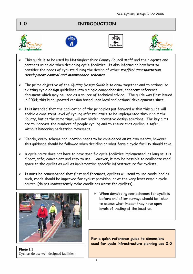
1.0 INTRODUCTION
For a quick reference guide to dimensions used for cycle infrastructure planning see 2.0
This guide is to be used by Nottinghamshire County Council staff and their agents and partners as an aid when designing cycle facilities. It also informs on how best to consider the needs of cyclists during the design of other traffic/ transportation, development control and maintenance schemes.
The prime objective of the Cycling Design Guide is to draw together and to rationalise
existing cycle design guidelines into a single comprehensive, coherent reference document which may be used as a source of technical advice. The guide was first issued in 2004; this is an updated version based upon local and national developments since.
It is intended that the application of the principles put forward within this guide will
enable a consistent level of cycling infrastructure to be implemented throughout the County, but at the same time, will not hinder innovative design solutions. The key aims are to increase the numbers of people cycling and to ensure that cycling is safer, without hindering pedestrian movement.
Clearly, every scheme and location needs to be considered on its own merits, however
this guidance should be followed when deciding on what form a cycle facility should take.
A cycle route does not have to have specific cycle facilities implemented, as long as it is direct, safe, convenient and easy to use. However, it may be possible to reallocate road space to the cyclist as well as implementing specific infrastructure for cyclists.
It must be remembered that first and foremost, cyclists will tend to use roads, and as
such, roads should be improved for cyclist provision, or at the very least remain cycle neutral (do not inadvertently make conditions worse for cyclists).
When developing new schemes for cyclists before and after surveys should be taken to assess what impact they have upon levels of cycling at the location.
Photo 1.1 Cyclists do use well designed facilities!
1
NCC Cycling Design Guide 2006
2
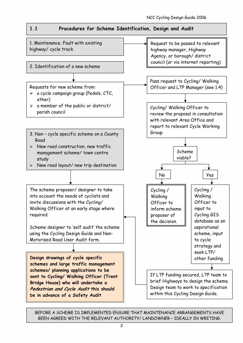
1.1 Procedures for Scheme Identification, Design and Audit
Pass request to Cycling/ Walking Officer and LTP Manager (see 1.4)Requests for new scheme from:
a cycle campaign group (Pedals, CTC, other)
a member of the public or district/ parish council
Cycling / Walking Officer to inform scheme proposer of the decision.
Cycling / Walking Officer to input to Cycling GIS database as an aspirational scheme, input to cycle strategy and seek LTP/ other funding
The scheme proposer/ designer to take into account the needs of cyclists and invite discussions with the Cycling/ Walking Officer at an early stage where required. Scheme designer to ‘self audit’ the scheme using the Cycling Design Guide and Non-Motorised Road User Audit form.
Design drawings of cycle specific schemes and large traffic management schemes/ planning applications to be sent to Cycling/ Walking Officer (Trent Bridge House) who will undertake a Pedestrian and Cycle Audit this should be in advance of a Safety Audit
If LTP funding secured, LTP team to brief Highways to design the scheme. Design team to work to specification within this Cycling Design Guide.
No
Scheme viable?
Cycling/ Walking Officer to review the proposal in consultation with relevant Area Office and report to relevant Cycle Working Group 3. Non – cycle specific scheme on a County
Road New road construction, new traffic
management scheme/ town centre study
New road layout/ new trip destination
2. Identification of a new scheme
Request to be passed to relevant highway manager, Highway Agency, or borough/ district council (or via internet reporting)
1. Maintenance. Fault with existing highway/ cycle track
Yes
BEFORE A SCHEME IS IMPLEMENTED ENSURE THAT MAINTENANCE ARRANGEMENTS HAVE BEEN AGREED WITH THE RELEVANT AUTHORITY/ LANDOWNER – IDEALLY IN WRITING.
NCC Cycling Design Guide 2006
3
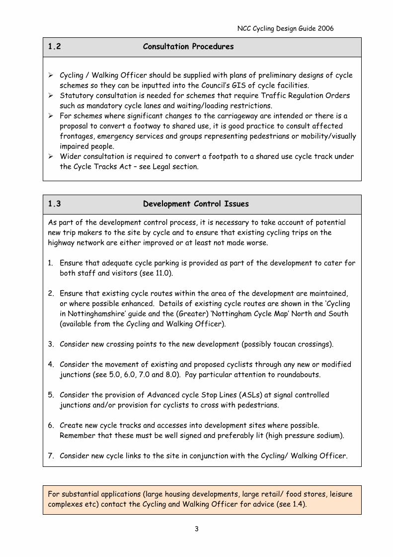
1.2 Consultation Procedures
Cycling / Walking Officer should be supplied with plans of preliminary designs of cycle
schemes so they can be inputted into the Council’s GIS of cycle facilities. Statutory consultation is needed for schemes that require Traffic Regulation Orders
such as mandatory cycle lanes and waiting/loading restrictions. For schemes where significant changes to the carriageway are intended or there is a
proposal to convert a footway to shared use, it is good practice to consult affected frontages, emergency services and groups representing pedestrians or mobility/visually impaired people.
Wider consultation is required to convert a footpath to a shared use cycle track under the Cycle Tracks Act – see Legal section.
As part of the development control process, it is necessary to take account of potential new trip makers to the site by cycle and to ensure that existing cycling trips on the highway network are either improved or at least not made worse. 1. Ensure that adequate cycle parking is provided as part of the development to cater for
both staff and visitors (see 11.0). 2. Ensure that existing cycle routes within the area of the development are maintained,
or where possible enhanced. Details of existing cycle routes are shown in the ‘Cycling in Nottinghamshire’ guide and the (Greater) ‘Nottingham Cycle Map’ North and South (available from the Cycling and Walking Officer).
3. Consider new crossing points to the new development (possibly toucan crossings). 4. Consider the movement of existing and proposed cyclists through any new or modified
junctions (see 5.0, 6.0, 7.0 and 8.0). Pay particular attention to roundabouts. 5. Consider the provision of Advanced cycle Stop Lines (ASLs) at signal controlled
junctions and/or provision for cyclists to cross with pedestrians. 6. Create new cycle tracks and accesses into development sites where possible.
Remember that these must be well signed and preferably lit (high pressure sodium). 7. Consider new cycle links to the site in conjunction with the Cycling/ Walking Officer.
1.3 Development Control Issues
For substantial applications (large housing developments, large retail/ food stores, leisure complexes etc) contact the Cycling and Walking Officer for advice (see 1.4).
NCC Cycling Design Guide 2006
4
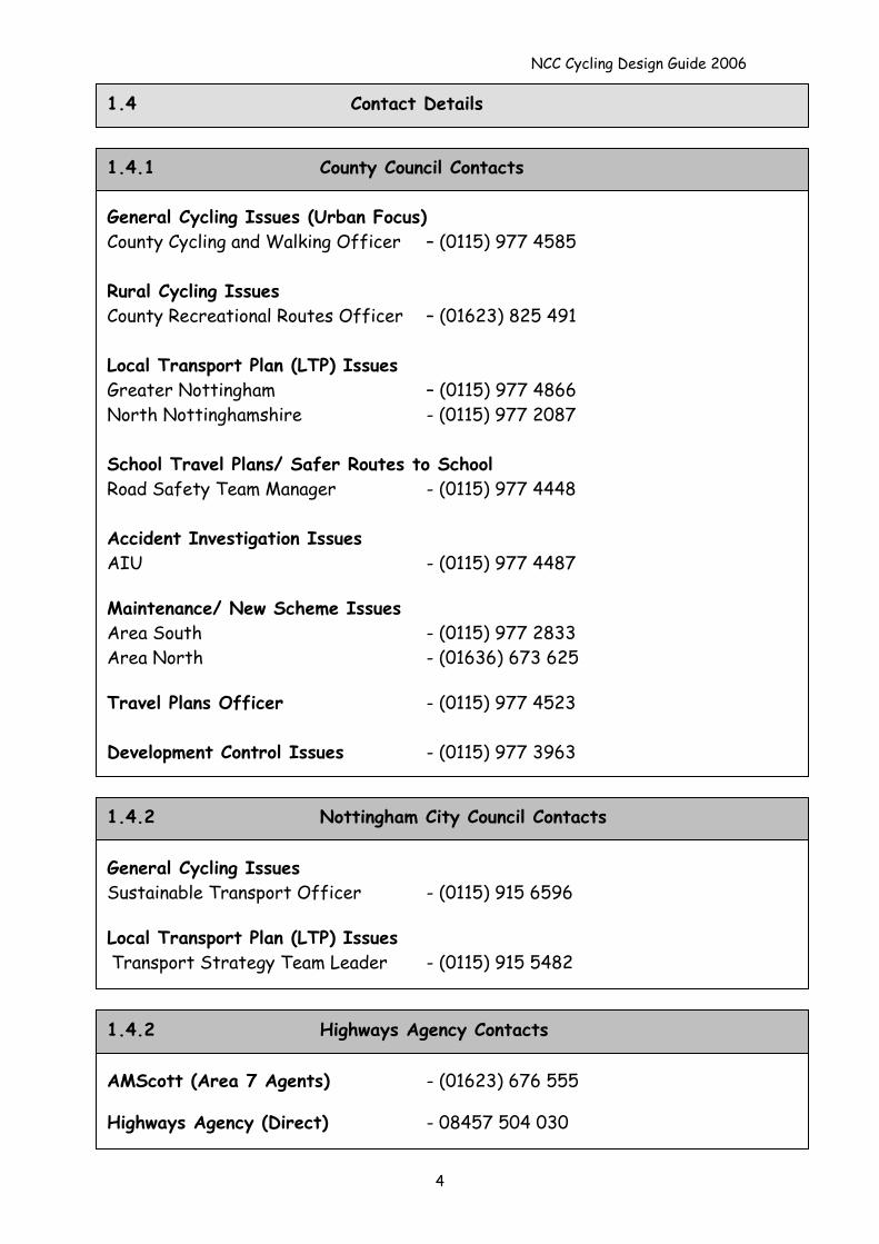
1.4 Contact Details
General Cycling Issues (Urban Focus) County Cycling and Walking Officer – (0115) 977 4585 Rural Cycling Issues County Recreational Routes Officer – (01623) 825 491 Local Transport Plan (LTP) Issues Greater Nottingham – (0115) 977 4866 North Nottinghamshire - (0115) 977 2087 School Travel Plans/ Safer Routes to School Road Safety Team Manager - (0115) 977 4448 Accident Investigation Issues AIU - (0115) 977 4487 Maintenance/ New Scheme Issues Area South - (0115) 977 2833 Area North - (01636) 673 625 Travel Plans Officer - (0115) 977 4523 Development Control Issues - (0115) 977 3963
1.4.1 County Council Contacts
General Cycling Issues Sustainable Transport Officer - (0115) 915 6596 Local Transport Plan (LTP) Issues Transport Strategy Team Leader - (0115) 915 5482
1.4.2 Nottingham City Council Contacts
AMScott (Area 7 Agents) - (01623) 676 555 Highways Agency (Direct) - 08457 504 030
1.4.2 Highways Agency Contacts
NCC Cycling Design Guide 2006
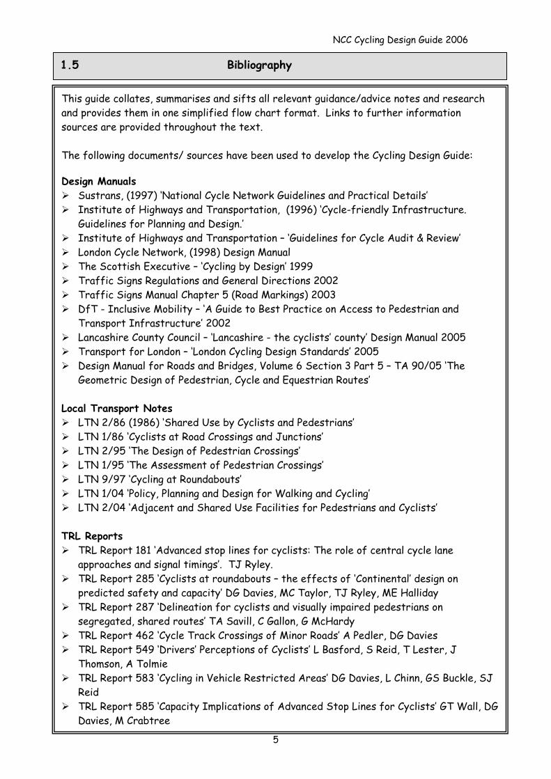
1.5 Bibliography
5
This guide collates, summarises and sifts all relevant guidance/advice notes and research and provides them in one simplified flow chart format. Links to further information sources are provided throughout the text. The following documents/ sources have been used to develop the Cycling Design Guide: Design Manuals
Sustrans, (1997) ‘National Cycle Network Guidelines and Practical Details’ Institute of Highways and Transportation, (1996) ‘Cycle-friendly Infrastructure.
Guidelines for Planning and Design.’ Institute of Highways and Transportation – ‘Guidelines for Cycle Audit & Review’ London Cycle Network, (1998) Design Manual The Scottish Executive – ‘Cycling by Design’ 1999 Traffic Signs Regulations and General Directions 2002 Traffic Signs Manual Chapter 5 (Road Markings) 2003 DfT - Inclusive Mobility – ‘A Guide to Best Practice on Access to Pedestrian and
Transport Infrastructure’ 2002 Lancashire County Council – ‘Lancashire - the cyclists’ county’ Design Manual 2005 Transport for London – ‘London Cycling Design Standards’ 2005 Design Manual for Roads and Bridges, Volume 6 Section 3 Part 5 – TA 90/05 ‘The
Geometric Design of Pedestrian, Cycle and Equestrian Routes’ Local Transport Notes
LTN 2/86 (1986) ‘Shared Use by Cyclists and Pedestrians’ LTN 1/86 ‘Cyclists at Road Crossings and Junctions’ LTN 2/95 ‘The Design of Pedestrian Crossings’ LTN 1/95 ‘The Assessment of Pedestrian Crossings’ LTN 9/97 ‘Cycling at Roundabouts’ LTN 1/04 ‘Policy, Planning and Design for Walking and Cycling’ LTN 2/04 ‘Adjacent and Shared Use Facilities for Pedestrians and Cyclists’
TRL Reports
TRL Report 181 ‘Advanced stop lines for cyclists: The role of central cycle lane approaches and signal timings’. TJ Ryley.
TRL Report 285 ‘Cyclists at roundabouts – the effects of ‘Continental’ design on predicted safety and capacity’ DG Davies, MC Taylor, TJ Ryley, ME Halliday
TRL Report 287 ‘Delineation for cyclists and visually impaired pedestrians on segregated, shared routes’ TA Savill, C Gallon, G McHardy
TRL Report 462 ‘Cycle Track Crossings of Minor Roads’ A Pedler, DG Davies TRL Report 549 ‘Drivers’ Perceptions of Cyclists’ L Basford, S Reid, T Lester, J
Thomson, A Tolmie TRL Report 583 ‘Cycling in Vehicle Restricted Areas’ DG Davies, L Chinn, GS Buckle, SJ
Reid TRL Report 585 ‘Capacity Implications of Advanced Stop Lines for Cyclists’ GT Wall, DG
Davies, M Crabtree
NCC Cycling Design Guide 2006
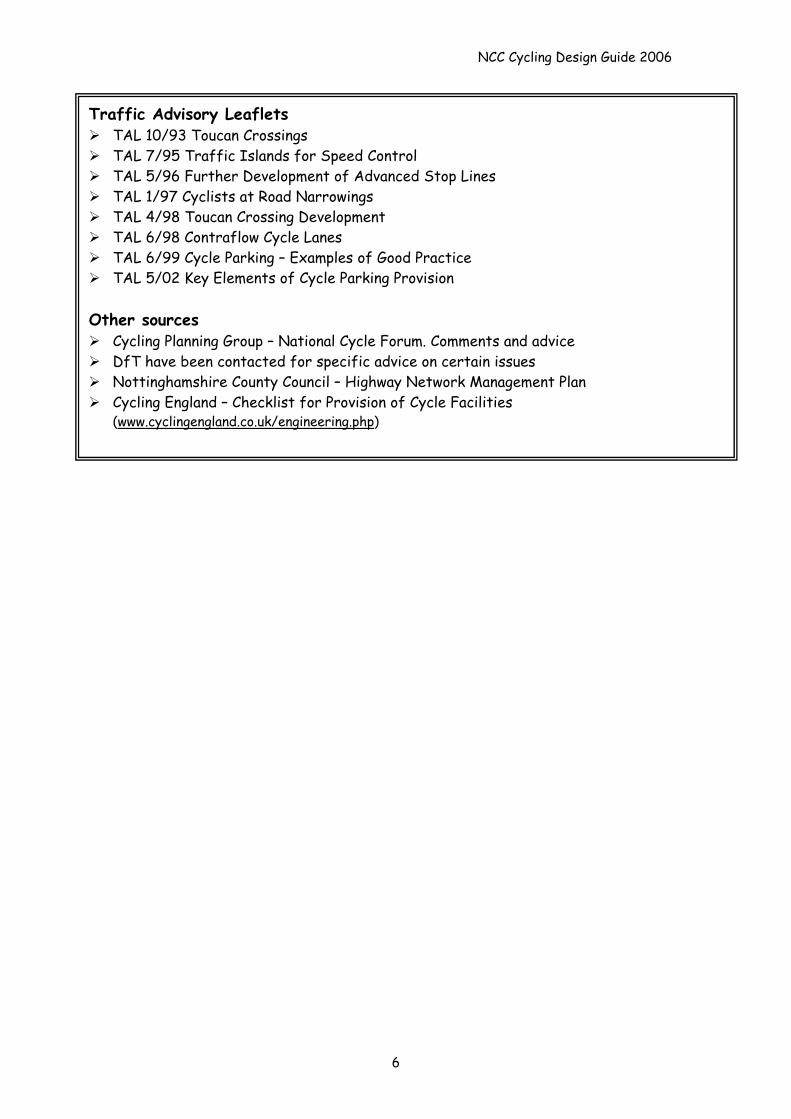
Traffic Advisory Leaflets TAL 10/93 Toucan Crossings TAL 7/95 Traffic Islands for Speed Control TAL 5/96 Further Development of Advanced Stop Lines TAL 1/97 Cyclists at Road Narrowings TAL 4/98 Toucan Crossing Development TAL 6/98 Contraflow Cycle Lanes TAL 6/99 Cycle Parking – Examples of Good Practice TAL 5/02 Key Elements of Cycle Parking Provision
Other sources
Cycling Planning Group – National Cycle Forum. Comments and advice DfT have been contacted for specific advice on certain issues Nottinghamshire County Council – Highway Network Management Plan Cycling England – Checklist for Provision of Cycle Facilities
(www.cyclingengland.co.uk/engineering.php)
6
NCC Cycling Design Guide 2006
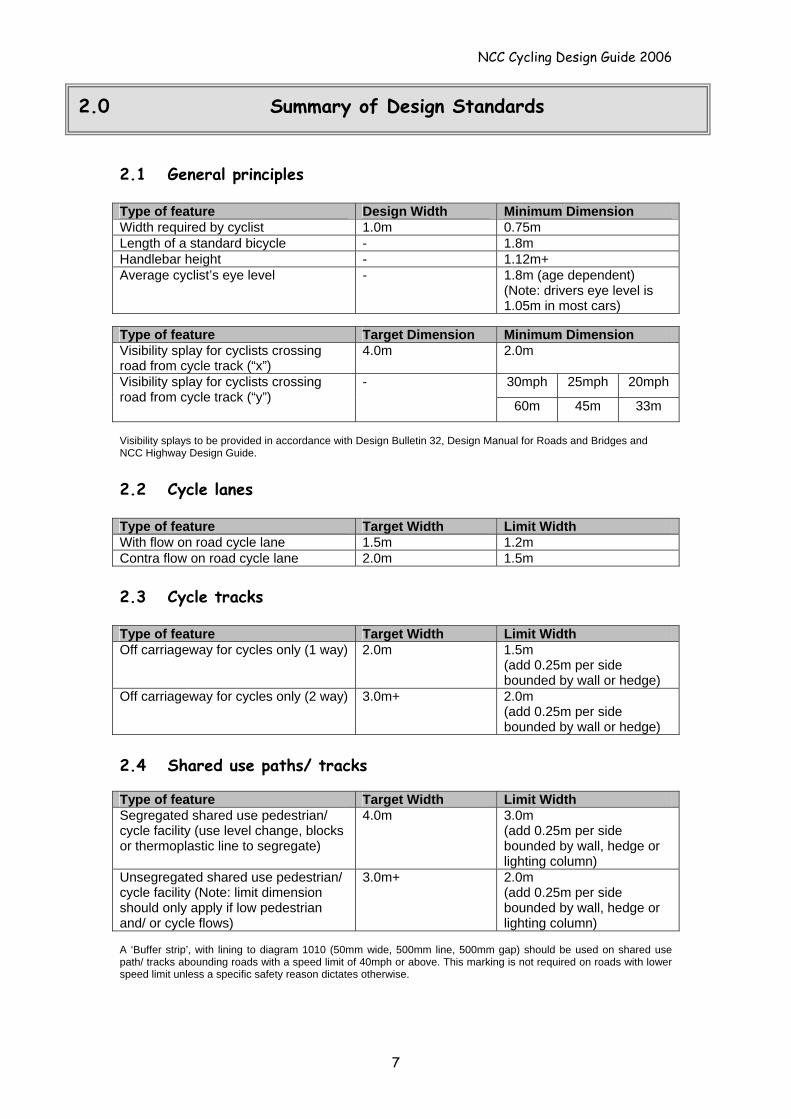
2.0 Summary of Design Standards
2.1 General principles Type of feature Design Width Minimum Dimension Width required by cyclist 1.0m 0.75m Length of a standard bicycle - 1.8m Handlebar height - 1.12m+ Average cyclist’s eye level - 1.8m (age dependent)
(Note: drivers eye level is 1.05m in most cars)
Type of feature Target Dimension Minimum Dimension Visibility splay for cyclists crossing road from cycle track (“x”)
4.0m 2.0m
30mph 25mph 20mph Visibility splay for cyclists crossing road from cycle track (“y”)
-
60m 45m 33m Visibility splays to be provided in accordance with Design Bulletin 32, Design Manual for Roads and Bridges and NCC Highway Design Guide. 2.2 Cycle lanes Type of feature Target Width Limit Width With flow on road cycle lane 1.5m 1.2m Contra flow on road cycle lane 2.0m 1.5m 2.3 Cycle tracks Type of feature Target Width Limit Width Off carriageway for cycles only (1 way) 2.0m 1.5m
(add 0.25m per side bounded by wall or hedge)
Off carriageway for cycles only (2 way) 3.0m+ 2.0m (add 0.25m per side bounded by wall or hedge)
2.4 Shared use paths/ tracks Type of feature Target Width Limit Width Segregated shared use pedestrian/ cycle facility (use level change, blocks or thermoplastic line to segregate)
4.0m 3.0m (add 0.25m per side bounded by wall, hedge or lighting column)
Unsegregated shared use pedestrian/ cycle facility (Note: limit dimension should only apply if low pedestrian and/ or cycle flows)
3.0m+ 2.0m (add 0.25m per side bounded by wall, hedge or lighting column)
A ‘Buffer strip’, with lining to diagram 1010 (50mm wide, 500mm line, 500mm gap) should be used on shared use path/ tracks abounding roads with a speed limit of 40mph or above. This marking is not required on roads with lower speed limit unless a specific safety reason dictates otherwise.
7
NCC Cycling Design Guide 2006
8
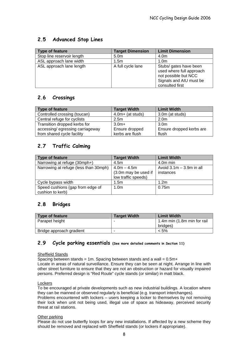
2.5 Advanced Stop Lines Type of feature Target Dimension Limit Dimension Stop line reservoir length 5.0m 4.0m ASL approach lane width 1.5m 1.0m ASL approach lane length A full cycle lane Stubs/ gates have been
used where full approach not possible but NCC Signals and AIU must be consulted first
2.6 Crossings Type of feature Target Width Limit Width Controlled crossing (toucan) 4.0m+ (at studs) 3.0m (at studs) Central refuge for cyclists 2.5m 2.0m Transition dropped kerbs for accessing/ egressing carriageway from shared cycle facility
3.0m+ Ensure dropped kerbs are flush
3.0m Ensure dropped kerbs are flush
2.7 Traffic Calming Type of feature Target Width Limit Width Narrowing at refuge (30mph+) 4.5m 4.0m min Narrowing at refuge (less than 30mph) 4.0m – 4.5m
(3.0m may be used if low traffic speeds)
Avoid 3.1m – 3.9m in all instances
Cycle bypass width 1.5m 1.2m Speed cushions (gap from edge of cushion to kerb)
1.0m 0.75m
2.8 Bridges Type of feature Target Width Limit Width Parapet height - 1.4m min (1.8m min for rail
bridges) Bridge approach gradient - < 5% 2.9 Cycle parking essentials (See more detailed comments in Section 11)
Sheffield Stands Spacing between stands = 1m. Spacing between stands and a wall = 0.5m+ Locate in areas of natural surveillance. Ensure they can be seen at night. Arrange in line with other street furniture to ensure that they are not an obstruction or hazard for visually impaired persons. Preferred design is “Red Route” cycle stands (or similar) in matt black. Lockers To be encouraged at private developments such as new industrial buildings. A location where they can be manned or observed regularly is beneficial (e.g. transport interchanges). Problems encountered with lockers – users keeping a locker to themselves by not removing their lock when unit not being used, illegal use of space as hideaway, perceived security threat at rail stations. Other parking Please do not use butterfly loops for any new installations. If affected by a new scheme they should be removed and replaced with Sheffield stands (or lockers if appropriate).
NCC Cycling Design Guide 2006
3.0 Cycle Route Planning - Choosing the Right Facility
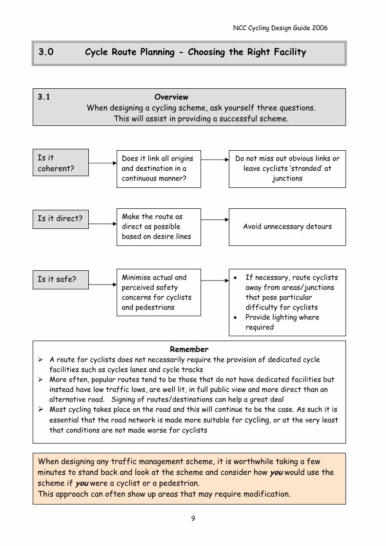
3.1 Overview When designing a cycling scheme, ask yourself three questions.
This will assist in providing a successful scheme.
Do not miss out obvious links or leave cyclists ‘stranded’ at
junctions
Does it link all origins and destination in a continuous manner?
Is it coherent?
Avoid unnecessary detours
Make the route as direct as possible based on desire lines
Is it direct?
• If necessary, route cyclists away from areas/junctions that pose particular difficulty for cyclists
• Provide lighting where required
Minimise actual and perceived safety concerns for cyclists and pedestrians
Is it safe?
Remember A route for cyclists does not necessarily require the provision of dedicated cycle
facilities such as cycles lanes and cycle tracks More often, popular routes tend to be those that do not have dedicated facilities but
instead have low traffic lows, are well lit, in full public view and more direct than an alternative road. Signing of routes/destinations can help a great deal
Most cycling takes place on the road and this will continue to be the case. As such it is essential that the road network is made more suitable for cycling, or at the very least that conditions are not made worse for cyclists
When designing any traffic management scheme, it is worthwhile taking a few minutes to stand back and look at the scheme and consider how you would use the scheme if you were a cyclist or a pedestrian. This approach can often show up areas that may require modification.
9
NCC Cycling Design Guide 2006
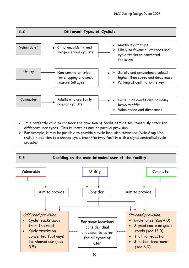
3.2 Different Types of Cyclists
It is perfectly valid to consider the provision of facilities that simultaneously cater for different user types. This is known as dual or parallel provision.
For example, it may be possible to provide a cycle lane with Advanced Cycle Stop Line (ASL) in addition to a shared cycle track/footway facility with a signal controlled cycle crossing.
‘Vulnerable ‘
Children, elderly, and inexperienced cyclists
‘Utility’
‘Commuter’
Non-commuter trips for shopping and social reasons (all ages)
Adults who are fairly regular cyclists
Safety and convenience valued higher than speed and directness
Parking at destination is key
Cycle in all conditions including heavy traffic
Value speed and directness
3.3 Deciding on the main intended user of the facility
Mostly short trips Likely to favour quiet roads and
cycle tracks on converted footways
Vulnerable Utility
Aim to provide Aim to provide Consider
Commuter
10
For some locations consider dual
provision to cater for all types of
user
On-road provision. • Cycle lanes (see 4.0) • Signed route on quiet
roads (see 13.0). • Traffic reduction • Junction treatment
(see 6.0)
Off road provision • Cycle tracks away
from the road • Cycle tracks on
converted footways i.e. shared use (see 3.5)
NCC Cycling Design Guide 2006
Source: IHT Cycle Friendly Infrastructure 1996 3.4 Hierarchy of Solutions for Cycle Provision
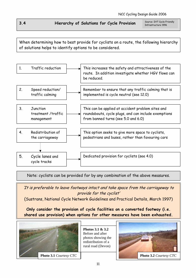
When determining how to best provide for cyclists on a route, the following hierarchy of solutions helps to identify options to be considered.
This increases the safety and attractiveness of the route. In addition investigate whether HGV flows can be reduced.
1. Traffic reduction
2. Speed reduction/ traffic calming
Remember to ensure that any traffic calming that is implemented is cycle neutral (see 12.0)
This can be applied at accident problem sites and roundabouts, cycle plugs, and can include exemptions from banned turns (see 5.0 and 6.0)
3. Junction treatment /traffic management
4. Redistribution of the carriageway
This option seeks to give more space to cyclists, pedestrians and buses, rather than favouring cars
Dedicated provision for cyclists (see 4.0) 5. Cycle lanes and cycle tracks
Note: cyclists can be provided for by any combination of the above measures.
‘It is preferable to leave footways intact and take space from the carriageway to provide for the cyclist’
(Sustrans, National Cycle Network Guidelines and Practical Details, March 1997)
Only consider the provision of cycle facilities on a converted footway (i.e. shared use provision) when options for other measures have been exhausted.
Photo 3.1 Courtesy CTC
Photos 3.1 & 3.2 Before and after photos showing the redistribution of a rural road (Devon)
Photo 3.2 Courtesy CTC
11
NCC Cycling Design Guide 2006
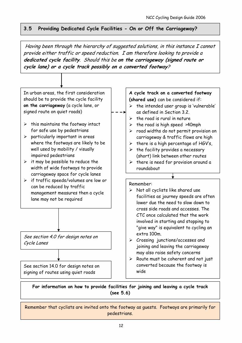
3.5 Providing Dedicated Cycle Facilities - On or Off the Carriageway?
Having been through the hierarchy of suggested solutions, in this instance I cannot provide either traffic or speed reduction. I am therefore looking to provide a dedicated cycle facility. Should this be on the carriageway (signed route or cycle lane) or a cycle track possibly on a converted footway?
A cycle track on a converted footway (shared use) can be considered if:
the intended user group is ‘vulnerable’ as defined in Section 3.2.
the road is rural in nature the road is high speed >40mph road widths do not permit provision on
carriageway & traffic flows are high there is a high percentage of HGV’s, the facility provides a necessary
(short) link between other routes there is need for provision around a
roundabout
In urban areas, the first consideration should be to provide the cycle facility on the carriageway (a cycle lane, or signed route on quiet roads)
this maintains the footway intact for safe use by pedestrians
particularly important in areas where the footways are likely to be well used by mobility / visually impaired pedestrians
it may be possible to reduce the width of wide footways to provide carriageway space for cycle lanes
if traffic speeds/volumes are low or can be reduced by traffic management measures then a cycle lane may not be required
Remember: Not all cyclists like shared use
facilities as journey speeds are often lower due the need to slow down to cross side roads and accesses. The CTC once calculated that the work involved in starting and stopping to "give way" is equivalent to cycling an extra 100m.
Crossing junctions/accesses and joining and leaving the carriageway may also raise safety concerns
Route must be coherent and not just converted because the footway is wide
See section 4.0 for design notes on Cycle Lanes
See section 14.0 for design notes on signing of routes using quiet roads
For information on how to provide facilities for joining and leaving a cycle track (see 5.6)
12
Remember that cyclists are invited onto the footway as guests. Footways are primarily for pedestrians.
NCC Cycling Design Guide 2006
13
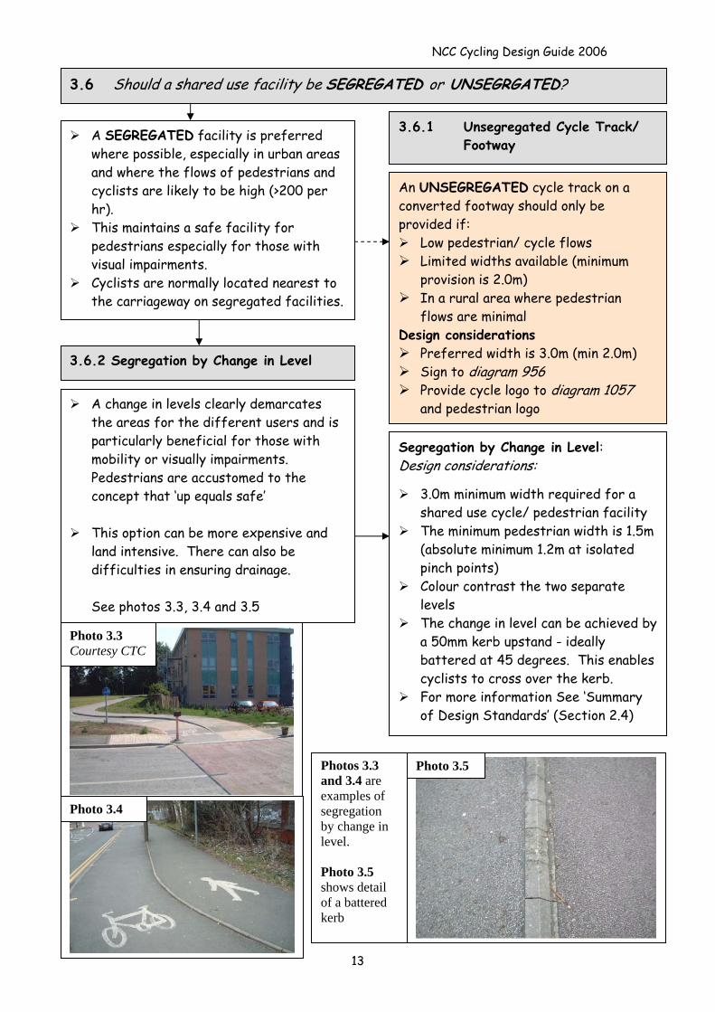
3.6 Should a shared use facility be SEGREGATED or UNSEGRGATED?
A SEGREGATED facility is preferred where possible, especially in urban areas and where the flows of pedestrians and cyclists are likely to be high (>200 per hr).
This maintains a safe facility for pedestrians especially for those with visual impairments.
Cyclists are normally located nearest to the carriageway on segregated facilities.
Photo 3.4
Photo 3.3 Courtesy CTC
Photos 3.3 and 3.4 are examples of segregation by change in level. Photo 3.5 shows detail of a battered kerb
Photo 3.5
An UNSEGREGATED cycle track on a converted footway should only be provided if:
Low pedestrian/ cycle flows Limited widths available (minimum
provision is 2.0m) In a rural area where pedestrian
flows are minimal Design considerations
Preferred width is 3.0m (min 2.0m) Sign to diagram 956 Provide cycle logo to diagram 1057
and pedestrian logo
Segregation by Change in Level: Design considerations:
3.0m minimum width required for a shared use cycle/ pedestrian facility
The minimum pedestrian width is 1.5m (absolute minimum 1.2m at isolated pinch points)
Colour contrast the two separate levels
The change in level can be achieved by a 50mm kerb upstand - ideally battered at 45 degrees. This enables cyclists to cross over the kerb.
For more information See ‘Summary of Design Standards’ (Section 2.4)
A change in levels clearly demarcates the areas for the different users and is particularly beneficial for those with mobility or visually impairments. Pedestrians are accustomed to the concept that ‘up equals safe’
This option can be more expensive and
land intensive. There can also be difficulties in ensuring drainage.
See photos 3.3, 3.4 and 3.5
3.6.1 Unsegregated Cycle Track/ Footway
3.6.2 Segregation by Change in Level
NCC Cycling Design Guide 2006
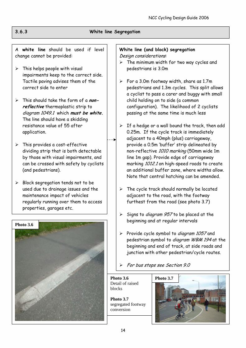
3.6.3 White line Segregation
A white line should be used if level change cannot be provided:
This helps people with visual impairments keep to the correct side. Tactile paving advises them of the correct side to enter
This should take the form of a non-reflective thermoplastic strip to diagram 1049.1 which must be white. The line should have a skidding resistance value of 55 after application.
This provides a cost-effective
dividing strip that is both detectable by those with visual impairments, and can be crossed with safety by cyclists (and pedestrians).
Block segregation tends not to be
used due to drainage issues and the maintenance impact of vehicles regularly running over them to access properties, garages etc.
White line (and block) segregation Design considerations:
The minimum width for two way cycles and pedestrians is 3.0m
For a 3.0m footway width, share as 1.7m
pedestrians and 1.3m cycles. This split allows a cyclist to pass a carer and buggy with small child holding on to side (a common configuration). The likelihood of 2 cyclists passing at the same time is much less
If a hedge or a wall bound the track, then add
0.25m. If the cycle track is immediately adjacent to a 40mph (plus) carriageway, provide a 0.5m ‘buffer’ strip delineated by non-reflective 1010 marking (50mm wide 1m line 1m gap). Provide edge of carriageway marking 1012.1 on high-speed roads to create an additional buffer zone, where widths allow. Note that central hatching can be amended.
The cycle track should normally be located
adjacent to the road, with the footway furthest from the road (see photo 3.7)
Signs to diagram 957 to be placed at the
beginning and at regular intervals
Provide cycle symbol to diagram 1057 and pedestrian symbol to diagram WBM 194 at the beginning and end of track, at side roads and junction with other pedestrian/cycle routes.
For bus stops see Section 9.0
Photo 3.7 Photo 3.6 Detail of raised blocks Photo 3.7 segregated footway conversion
Photo 3.6
14
NCC Cycling Design Guide 2006
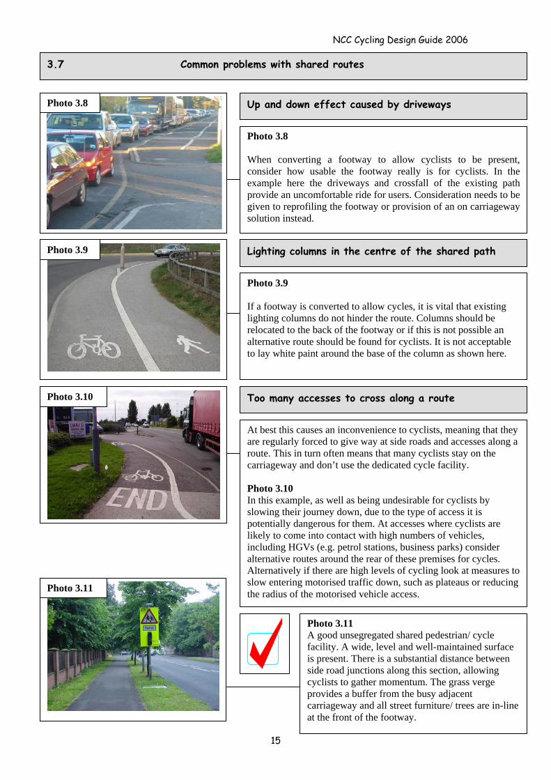
3.7 Common problems with shared routes
15
Photo 3.8 Up and down effect caused by driveways
Photo 3.8 When converting a footway to allow cyclists to be present, consider how usable the footway really is for cyclists. In the example here the driveways and crossfall of the existing path provide an uncomfortable ride for users. Consideration needs to be given to reprofiling the footway or provision of an on carriageway solution instead.
Photo 3.9 Lighting columns in the centre of the shared path
Photo 3.9 If a footway is converted to allow cycles, it is vital that existing lighting columns do not hinder the route. Columns should be relocated to the back of the footway or if this is not possible an alternative route should be found for cyclists. It is not acceptable to lay white paint around the base of the column as shown here.
Photo 3.11
Too many accesses to cross along a route
At best this causes an inconvenience to cyclists, meaning that they are regularly forced to give way at side roads and accesses along a route. This in turn often means that many cyclists stay on the carriageway and don’t use the dedicated cycle facility. Photo 3.10 In this example, as well as being undesirable for cyclists by slowing their journey down, due to the type of access it is potentially dangerous for them. At accesses where cyclists are likely to come into contact with high numbers of vehicles, including HGVs (e.g. petrol stations, business parks) consider alternative routes around the rear of these premises for cycles. Alternatively if there are high levels of cycling look at measures to slow entering motorised traffic down, such as plateaus or reducing the radius of the motorised vehicle access.
Photo 3.10
Photo 3.11 A good unsegregated shared pedestrian/ cycle facility. A wide, level and well-maintained surface is present. There is a substantial distance between side road junctions along this section, allowing cyclists to gather momentum. The grass verge provides a buffer from the busy adjacent carriageway and all street furniture/ trees are in-line at the front of the footway.
NCC Cycling Design Guide 2006
3.8 Tactile paving for shared routes
Photo 3.12
General tactile and dropped kerb issues:
Upstand at dropped kerb – flush on cycle routes
Tactile depth – 1200mm when in-line for pedestrians, 400mm when off direct line of travel (this is less likely to apply on a cycle route than just indented dropped kerbs on a normal footpath), 800mm for crossings away from junctions (e.g. dropped kerbs leading to a central refuge). At all controlled junctions the tactile depth is to be a minimum of 800mm (1200mm if it is in-line)
Opposite dropped kerbs to line up Gradient on approach to dropped kerb
should be 1 in 20 (1 in 12 absolute max)
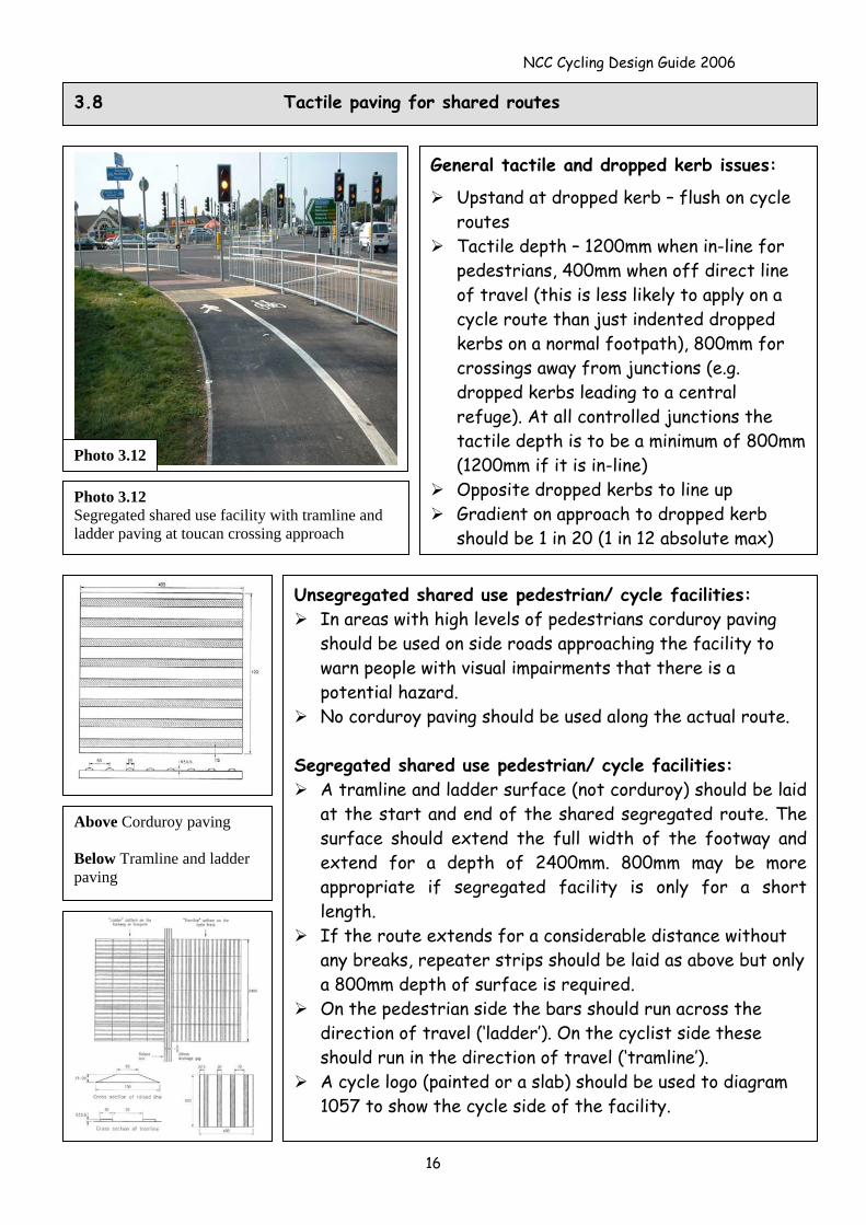
Photo 3.12 Segregated shared use facility with tramline and ladder paving at toucan crossing approach
Above Corduroy paving Below Tramline and ladder paving
Unsegregated shared use pedestrian/ cycle facilities: In areas with high levels of pedestrians corduroy paving
should be used on side roads approaching the facility to warn people with visual impairments that there is a potential hazard.
No corduroy paving should be used along the actual route. Segregated shared use pedestrian/ cycle facilities:
A tramline and ladder surface (not corduroy) should be laid at the start and end of the shared segregated route. The surface should extend the full width of the footway and extend for a depth of 2400mm. 800mm may be more appropriate if segregated facility is only for a short length.
If the route extends for a considerable distance without any breaks, repeater strips should be laid as above but only a 800mm depth of surface is required.
On the pedestrian side the bars should run across the direction of travel (‘ladder’). On the cyclist side these should run in the direction of travel (‘tramline’).
A cycle logo (painted or a slab) should be used to diagram 1057 to show the cycle side of the facility.
16
NCC Cycling Design Guide 2006
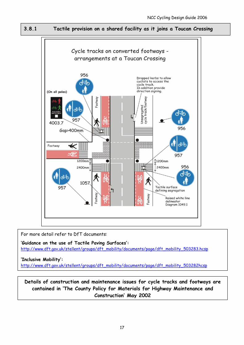
3.8.1 Tactile provision on a shared facility as it joins a Toucan Crossing
For more detail refer to DfT documents:
‘Guidance on the use of Tactile Paving Surfaces’: http://www.dft.gov.uk/stellent/groups/dft_mobility/documents/page/dft_mobility_503283.hcsp
‘Inclusive Mobility’: http://www.dft.gov.uk/stellent/groups/dft_mobility/documents/page/dft_mobility_503282hcsp
Details of construction and maintenance issues for cycle tracks and footways are contained in ‘The County Policy for Materials for Highway Maintenance and
Construction’ May 2002
17
NCC Cycling Design Guide 2006
4.0 Cycle Lanes
Raises drivers’ awareness to the presence of cyclists (particularly at side roads) Cyclists’ generally feel safer when using cycle lanes They enable cyclists to bypass queuing traffic Shows a clear commitment to improving conditions for cyclists
4.1 With Flow Cycle Lanes – Benefits
Preferred width 1.5m, min. width 1.2m, (absolute min width for short sections 1.0m) If cycle lane is on an uphill gradient, provide as wide a cycle lane as possible to account for
‘uphill wobble’ The adjacent traffic lane should ideally 3.0m or more, however, narrower widths (for
advisory cycle lanes only) can be provided on quieter roads – for an example see photo 4.3 Take care when providing cycle lanes in situations where there are parking bays. Do not
place cyclists in a situation where they are disadvantaged by using the lane (see 4.3) Wide nearside lanes can be considered as an alternative to cycle lanes Before creating lanes, inspect the road surface and improve covers/ gullies as required If traffic lanes widths are narrow and footways wide, consider widening the carriageway or
(as a last resort) providing a shared use facility on one of the footways For details on how to join to/from a cycle track on a converted footway see 5.6
4.1.1 Cycle Lanes - General design
18
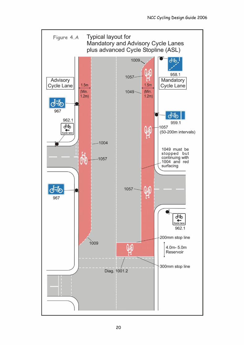
4.2 Mandatory With-Flow Cycle Lanes (see Fig4.A)
Lining: Use diagram 1009 at start of the lane Then provide 150mm solid white line to diagram
1049. This line must be stopped at all side road junctions, but not cross-overs to private residences. They must also be stopped at zebra, puffin/pelican, toucan and signal controlled crossings
Advisory cycle lane markings to diagram 1004 can be used across side roads to maintain continuity
Provide red surfacing as required in line with County Policy
Cycle logo 1057 to be used at the start and at frequent intervals along the lane (50-200m). They should also be used across side roads
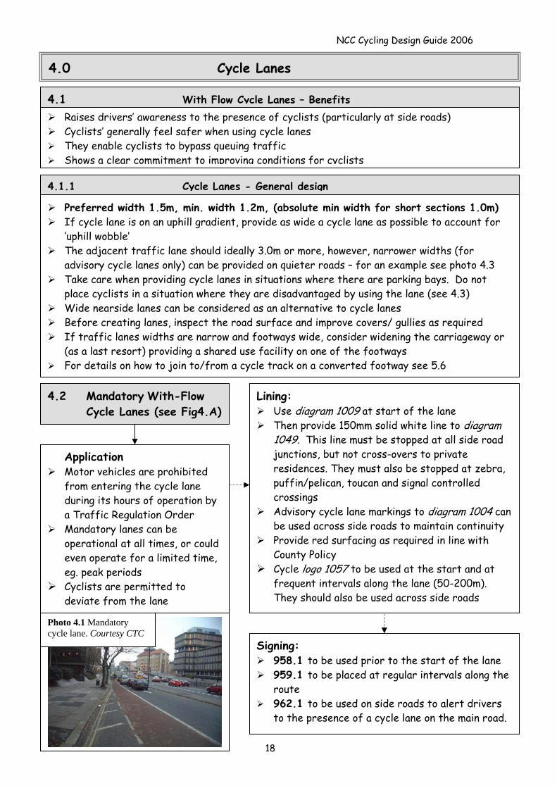
Photo 4.1 Mandatory cycle lane. Courtesy CTC
Application Motor vehicles are prohibited
from entering the cycle lane during its hours of operation by a Traffic Regulation Order
Mandatory lanes can be operational at all times, or could even operate for a limited time, eg. peak periods
Cyclists are permitted to deviate from the lane
Signing: 958.1 to be used prior to the start of the lane 959.1 to be placed at regular intervals along the
route 962.1 to be used on side roads to alert drivers
to the presence of a cycle lane on the main road.
NCC Cycling Design Guide 2006
4.3 Advisory With-Flow Cycle Lanes (see Fig 4.A)
Lining: Use diagram 1009 at start of the lane.
Use broken white line to diagram 1004 for the
cycle lane. These markings must be stopped at zig-zag marking for zebra and puffin/pelican, crossings and at yellow bus stop cage markings, but can be taken across side roads.
Ideally red surfacing should be provided in line with County policy – especially crossing side roads.
Cycle logo to diagram 1057 to be used at the start and at frequent intervals (50-200m). They should also be used across side roads (at the mid point of the minor road junction). Use in combination with sign 967.
Application: No statutory procedures are
required for the implementation of an advisory cycle lane.
Motor vehicles are allowed to enter the cycle lane marking
Advisory cycle lanes can suffer from on-street parking, although peak hour waiting and loading restrictions could be considered as part of a scheme.
Take care when providing cycle lanes where there is a central refuge
Consider the provision of cycle lanes when roads are re-surfaced.
Signing: 967 to be used to emphasise the lane (provide at
start and repeat as required, in combination with marking 1057)
962.1 can be used on side roads to alert drivers to the presence of a cycle lane on the main road Parking bays
Cycle lanes can be continued around the outside of parking/loading bays
The cycle lane should be 1.5m wide and ideally be red surfaced
Use diagram. 1004 A buffer zone of 1.0m should be
provided between the edge of the parking bay and the cycle lane, to allow for car doors opening (0.5m min.)
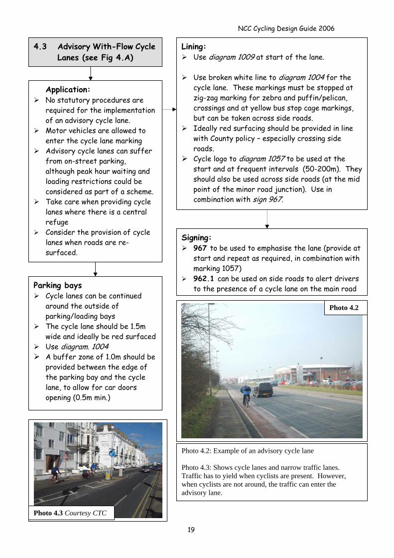
Photo 4.2
Photo 4.3 Courtesy CTC
Photo 4.2: Example of an advisory cycle lane Photo 4.3: Shows cycle lanes and narrow traffic lanes. Traffic has to yield when cyclists are present. However, when cyclists are not around, the traffic can enter the advisory lane.
19
NCC Cycling Design Guide 2006
Figure 4.A
20
NCC Cycling Design Guide 2006
4.4 Innovative Two-Way Segregated Cycle Lanes
Photo 4.4 Courtesy Alex Sully
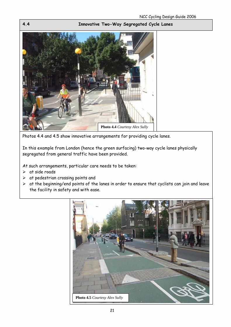
Photos 4.4 and 4.5 show innovative arrangements for providing cycle lanes. In this example from London (hence the green surfacing) two-way cycle lanes physically segregated from general traffic have been provided. At such arrangements, particular care needs to be taken:
at side roads at pedestrian crossing points and at the beginning/end points of the lanes in order to ensure that cyclists can join and leave
the facility in safety and with ease.
Photo 4.5 Courtesy Alex Sully
21
NCC Cycling Design Guide 2006
4.5 Contra-Flow Cycle Lanes and Cycle Exemptions
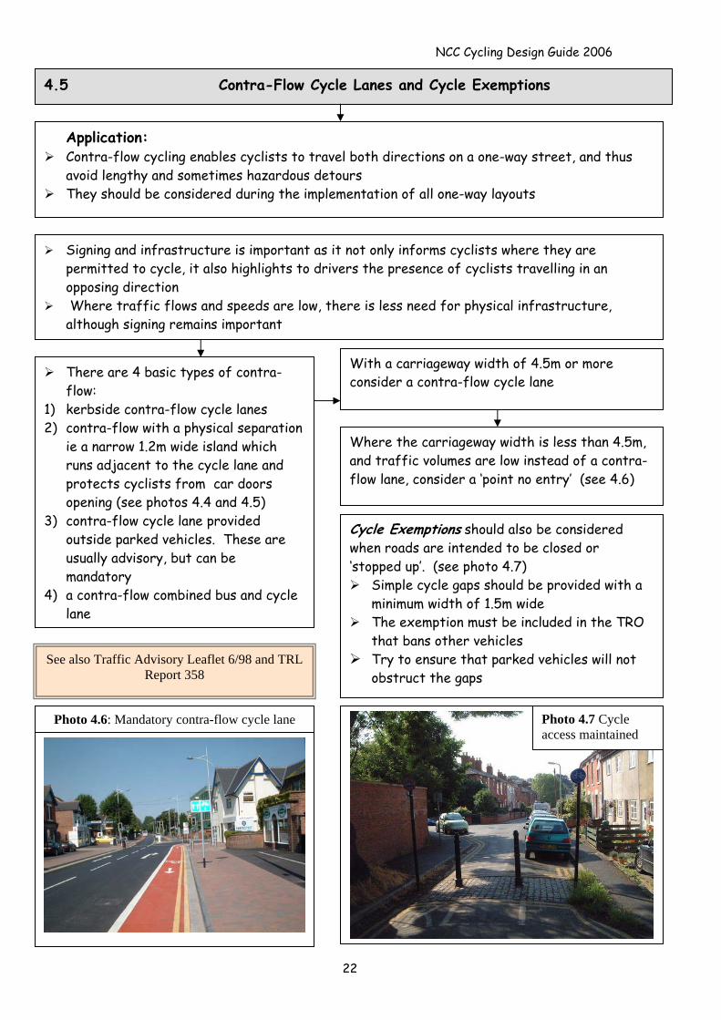
Application: Contra-flow cycling enables cyclists to travel both directions on a one-way street, and thus
avoid lengthy and sometimes hazardous detours They should be considered during the implementation of all one-way layouts
There are 4 basic types of contra-flow:
1) kerbside contra-flow cycle lanes 2) contra-flow with a physical separation
ie a narrow 1.2m wide island which runs adjacent to the cycle lane and protects cyclists from car doors opening (see photos 4.4 and 4.5)
3) contra-flow cycle lane provided outside parked vehicles. These are usually advisory, but can be mandatory
4) a contra-flow combined bus and cycle lane
With a carriageway width of 4.5m or more consider a contra-flow cycle lane
Signing and infrastructure is important as it not only informs cyclists where they are permitted to cycle, it also highlights to drivers the presence of cyclists travelling in an opposing direction
Where traffic flows and speeds are low, there is less need for physical infrastructure, although signing remains important
Where the carriageway width is less than 4.5m, and traffic volumes are low instead of a contra-flow lane, consider a ‘point no entry’ (see 4.6)
Cycle Exemptions should also be considered when roads are intended to be closed or ‘stopped up’. (see photo 4.7)
Simple cycle gaps should be provided with a minimum width of 1.5m wide
The exemption must be included in the TRO that bans other vehicles
Try to ensure that parked vehicles will not obstruct the gaps
See also Traffic Advisory Leaflet 6/98 and TRL Report 358
Photo 4.6: Mandatory contra-flow cycle lane Photo 4.7 Cycle access maintained
22
NCC Cycling Design Guide 2006
Fig. 3.3
Figures 4.B to 4.D based on TAL 6/98
Fig 4C
Fig4.B
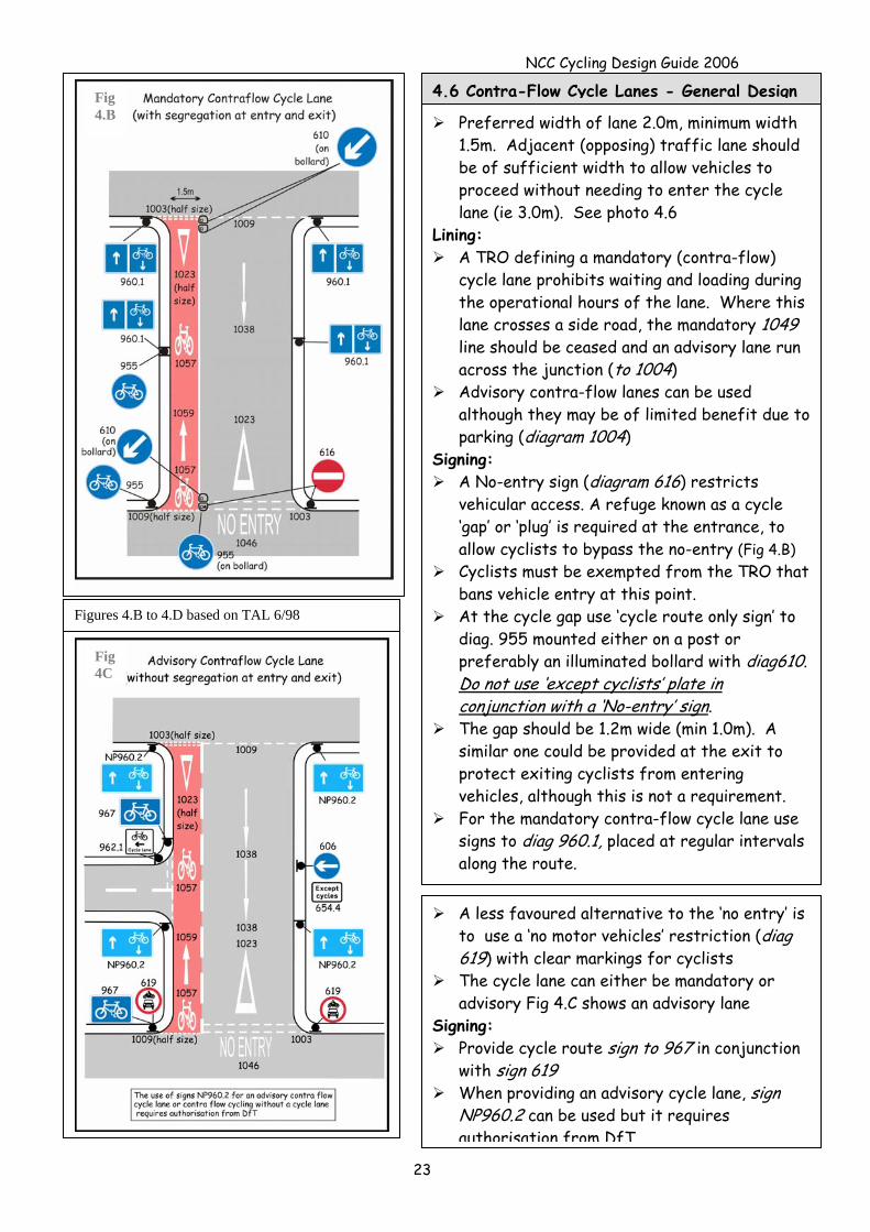
4.6 Contra-Flow Cycle Lanes - General Design
Preferred width of lane 2.0m, minimum width 1.5m. Adjacent (opposing) traffic lane should be of sufficient width to allow vehicles to proceed without needing to enter the cycle lane (ie 3.0m). See photo 4.6
Lining: A TRO defining a mandatory (contra-flow)
cycle lane prohibits waiting and loading during the operational hours of the lane. Where this lane crosses a side road, the mandatory 1049 line should be ceased and an advisory lane run across the junction (to 1004)
Advisory contra-flow lanes can be used although they may be of limited benefit due to parking (diagram 1004)
Signing: A No-entry sign (diagram 616) restricts
vehicular access. A refuge known as a cycle ‘gap’ or ‘plug’ is required at the entrance, to allow cyclists to bypass the no-entry (Fig 4.B)
Cyclists must be exempted from the TRO that bans vehicle entry at this point.
At the cycle gap use ‘cycle route only sign’ to diag. 955 mounted either on a post or preferably an illuminated bollard with diag610. Do not use ‘except cyclists’ plate in conjunction with a ‘No-entry’ sign.
The gap should be 1.2m wide (min 1.0m). A similar one could be provided at the exit to protect exiting cyclists from entering vehicles, although this is not a requirement.
For the mandatory contra-flow cycle lane use signs to diag 960.1, placed at regular intervals along the route.
A less favoured alternative to the ‘no entry’ is to use a ‘no motor vehicles’ restriction (diag 619) with clear markings for cyclists
The cycle lane can either be mandatory or advisory Fig 4.C shows an advisory lane
Signing: Provide cycle route sign to 967 in conjunction
with sign 619 When providing an advisory cycle lane, sign
NP960.2 can be used but it requires authorisation from DfT
23
NCC Cycling Design Guide 2006
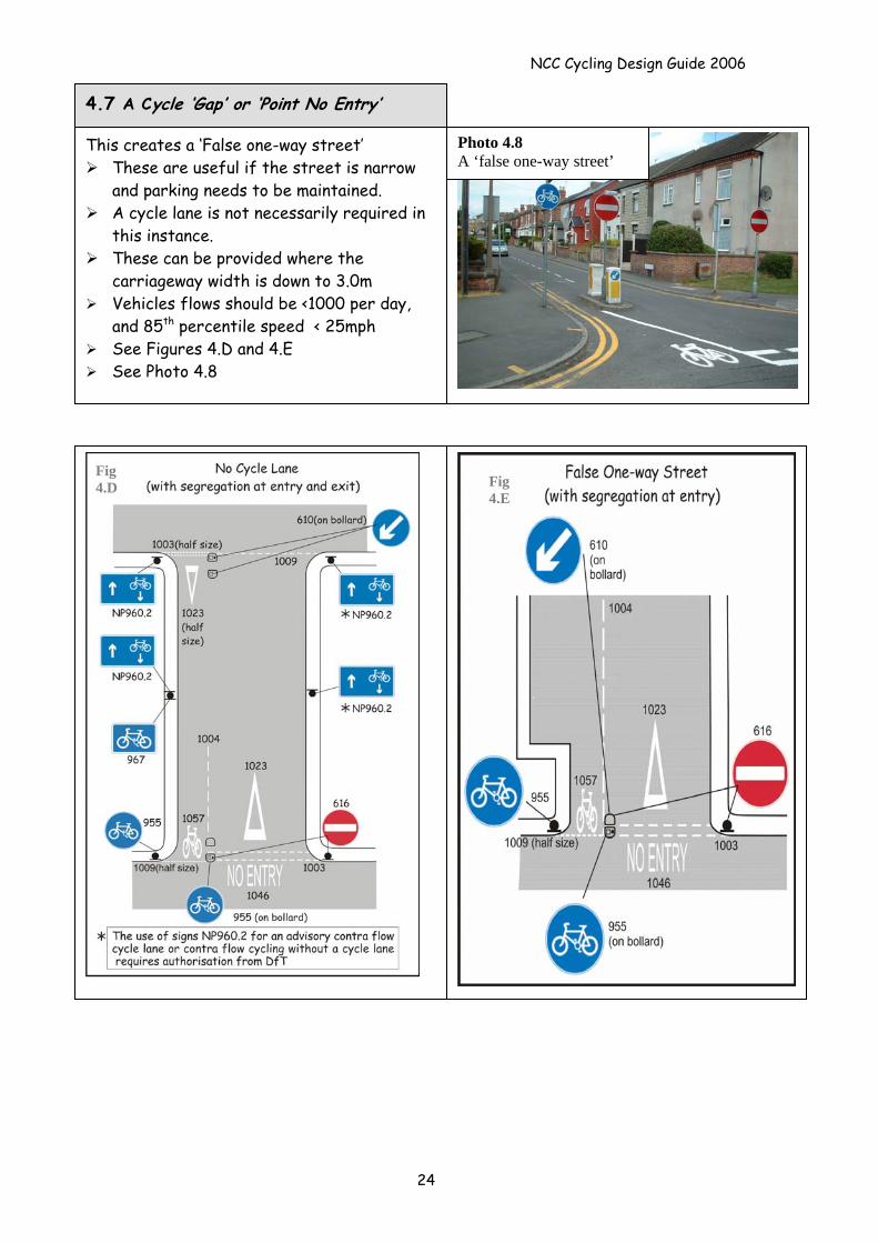
This creates a ‘False one-way street’
These are useful if the street is narrow and parking needs to be maintained.
A cycle lane is not necessarily required in this instance.
These can be provided where the carriageway width is down to 3.0m
Vehicles flows should be <1000 per day, and 85th percentile speed < 25mph
See Figures 4.D and 4.E See Photo 4.8
4.7 A Cycle ‘Gap’ or ‘Point No Entry’
Photo 4.8 A ‘false one-way street’
Fig 4.D Fig
4.E
24
NCC Cycling Design Guide 2006
25
5.0 Designs for specific manoeuvres
This section provides advice on providing for cycle track crossing points of major and minor roads and also suggests methods for assisting cyclists who wish to make a right turn (see 5.4) Information regarding priority and signal controlled arrangements is provided in Section 6.0
5.1 Design Principles
Cyclists should be within the normal field of vision for drivers. ‘Designs that place the cyclist in front of and reasonably close to the driver tend to be safer’ (IHT 1997)
Free flowing arrangements including segregated left turn lanes and merge lanes can
be particularly hazardous for cyclists
5.2 Cycle Track Crossings at Level Crossings
These require special attention and early discussion with the railway infrastructure company and the HMRI is required
Any traffic signs and road /footway markings over the crossing will need to be authorised in a revised Level Crossing Order
5.3 Cycle Provision Where a Main Road Crosses a Minor Road
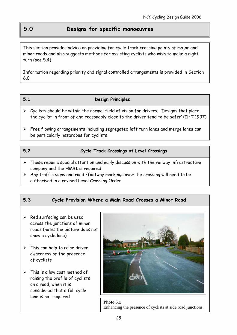
Red surfacing can be used
across the junctions of minor roads (note: the picture does not show a cycle lane)
This can help to raise driver
awareness of the presence of cyclists
This is a low cost method of
raising the profile of cyclists on a road, when it is considered that a full cycle lane is not required
Photo 5.1 Enhancing the presence of cyclists at side road junctions
NCC Cycling Design Guide 2006
26
Crossing a Minor Road/ Private access Crossing a Major Road
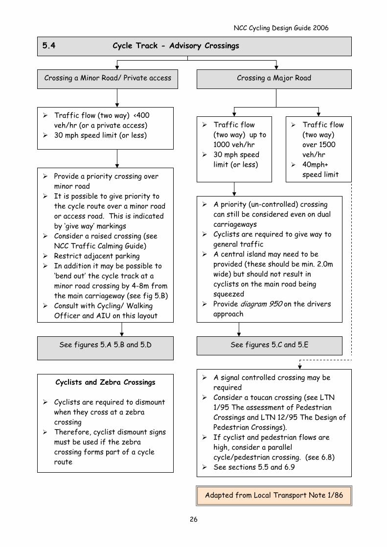
Traffic flow (two way) up to 1000 veh/hr
30 mph speed limit (or less)
A priority (un-controlled) crossing can still be considered even on dual carriageways
Cyclists are required to give way to general traffic
A central island may need to be provided (these should be min. 2.0m wide) but should not result in cyclists on the main road being squeezed
Provide diagram 950 on the drivers approach
Traffic flow (two way) over 1500 veh/hr
40mph+ speed limit Provide a priority crossing over
minor road It is possible to give priority to
the cycle route over a minor road or access road. This is indicated by ‘give way’ markings
Consider a raised crossing (see NCC Traffic Calming Guide)
Restrict adjacent parking In addition it may be possible to
‘bend out’ the cycle track at a minor road crossing by 4-8m from the main carriageway (see fig 5.B)
Consult with Cycling/ Walking Officer and AIU on this layout
Traffic flow (two way) <400 veh/hr (or a private access)
30 mph speed limit (or less)
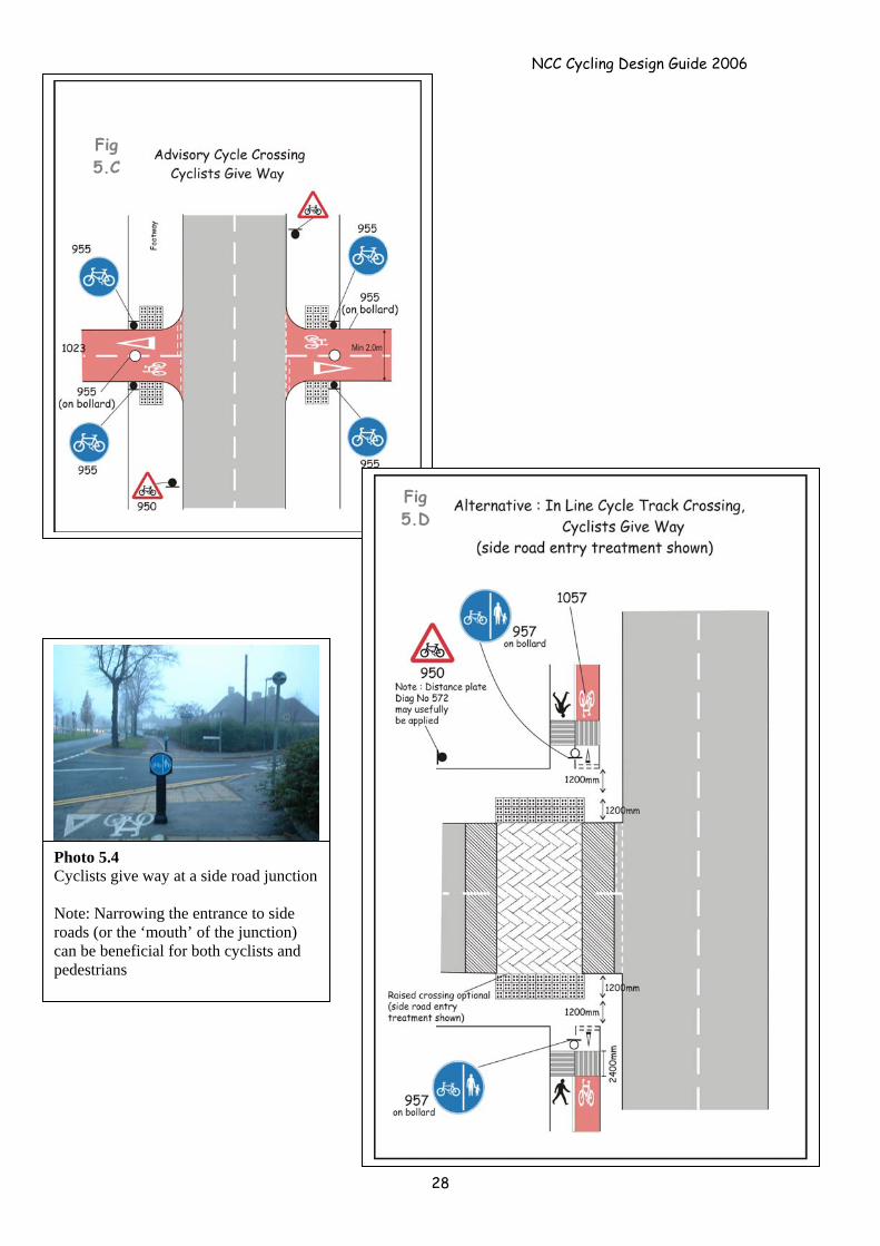
5.4 Cycle Track - Advisory Crossings
See figures 5.A 5.B and 5.D See figures 5.C and 5.E
A signal controlled crossing may be required
Consider a toucan crossing (see LTN 1/95 The assessment of Pedestrian Crossings and LTN 12/95 The Design of Pedestrian Crossings).
If cyclist and pedestrian flows are high, consider a parallel cycle/pedestrian crossing. (see 6.8)
See sections 5.5 and 6.9
Cyclists and Zebra Crossings
Cyclists are required to dismount when they cross at a zebra crossing
Therefore, cyclist dismount signs must be used if the zebra crossing forms part of a cycle route
Adapted from Local Transport Note 1/86
NCC Cycling Design Guide 2006
Poop Popo
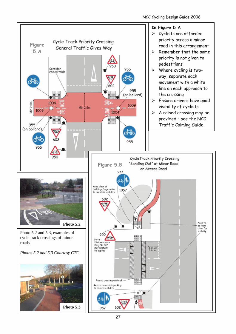
Photo 5.2
Photo 5.2 and 5.3, examples of cycle track crossings of minor roads Photos 5.2 and 5.3 Courtesy CTC
Photo 5.3
In Figure 5.A Cyclists are afforded
priority across a minor road in this arrangement
Remember that the same priority is not given to pedestrians
Where cycling is two-way, separate each movement with a white line on each approach to the crossing
Ensure drivers have good visibility of cyclists
A raised crossing may be provided – see the NCC Traffic Calming Guide
Figure 5.B
Figure 5.A
27
NCC Cycling Design Guide 2006
Polo zoo
Photo 5.4 Cyclists give way at a side road junction Note: Narrowing the entrance to side roads (or the ‘mouth’ of the junction) can be beneficial for both cyclists and pedestrians
Fig 5.D
Fig 5.C
28
NCC Cycling Design Guide 2006
Polp Plopo
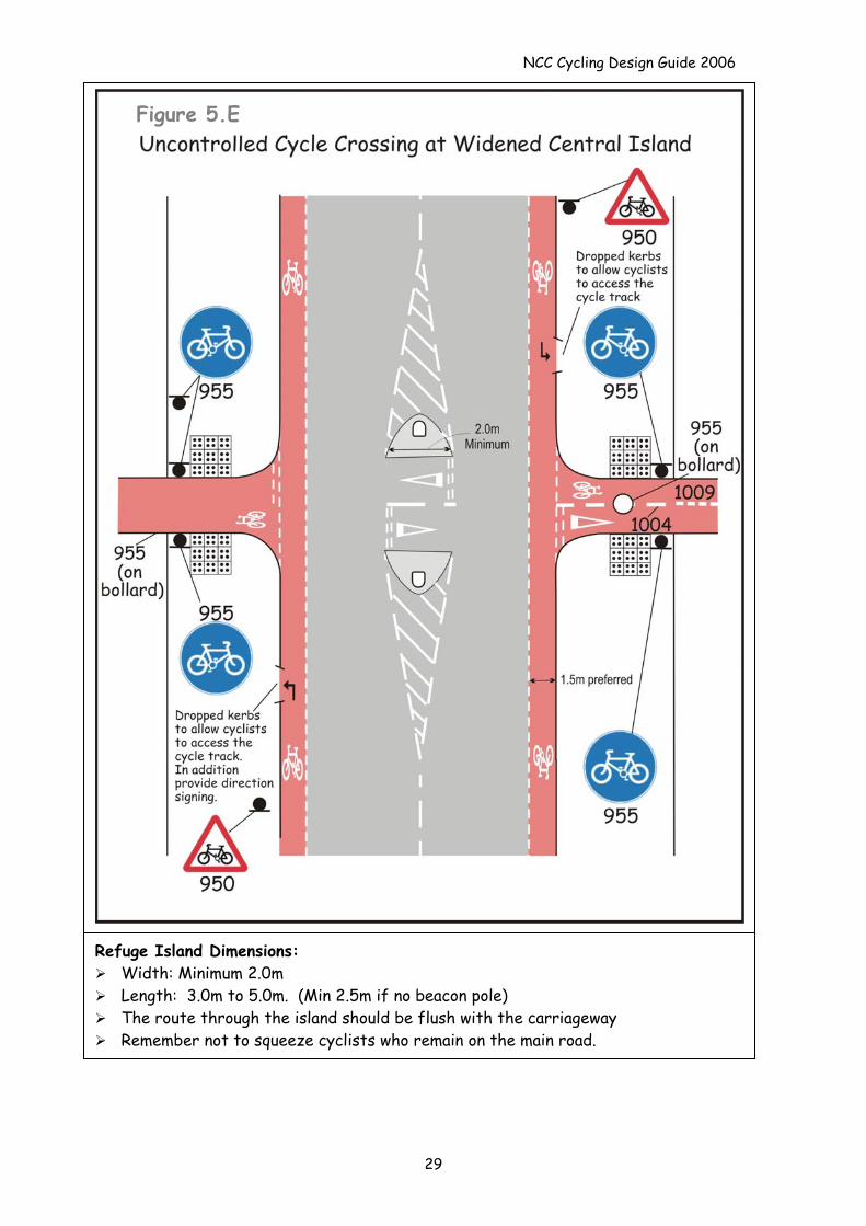
Refuge Island Dimensions: Width: Minimum 2.0m Length: 3.0m to 5.0m. (Min 2.5m if no beacon pole) The route through the island should be flush with the carriageway Remember not to squeeze cyclists who remain on the main road.
Figure 5.E
29
NCC Cycling Design Guide 2006
30
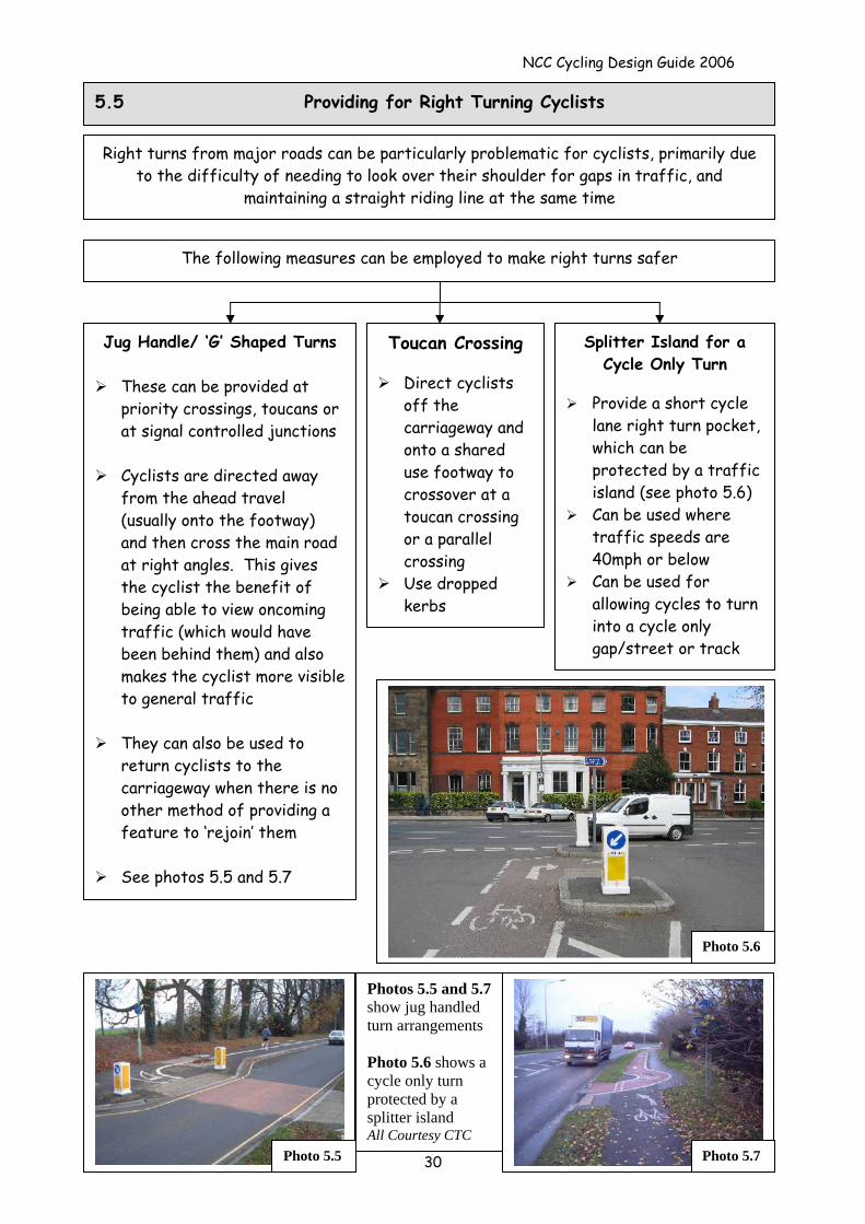
5.5 Providing for Right Turning Cyclists
Right turns from major roads can be particularly problematic for cyclists, primarily due to the difficulty of needing to look over their shoulder for gaps in traffic, and
maintaining a straight riding line at the same time
The following measures can be employed to make right turns safer
Jug Handle/ ‘G’ Shaped Turns
These can be provided at priority crossings, toucans or at signal controlled junctions
Cyclists are directed away
from the ahead travel (usually onto the footway) and then cross the main road at right angles. This gives the cyclist the benefit of being able to view oncoming traffic (which would have been behind them) and also makes the cyclist more visible to general traffic
They can also be used to
return cyclists to the carriageway when there is no other method of providing a feature to ‘rejoin’ them
See photos 5.5 and 5.7
Toucan Crossing
Direct cyclists off the carriageway and onto a shared use footway to crossover at a toucan crossing or a parallel crossing
Use dropped kerbs
Splitter Island for a Cycle Only Turn
Provide a short cycle
lane right turn pocket, which can be protected by a traffic island (see photo 5.6)
Can be used where traffic speeds are 40mph or below
Can be used for allowing cycles to turn into a cycle only gap/street or track
Photo 5.6
Photo 5.5
Photos 5.5 and 5.7show jug handled turn arrangements Photo 5.6 shows a cycle only turn protected by a splitter island All Courtesy CTC
Photo 5.7
NCC Cycling Design Guide 2006
31
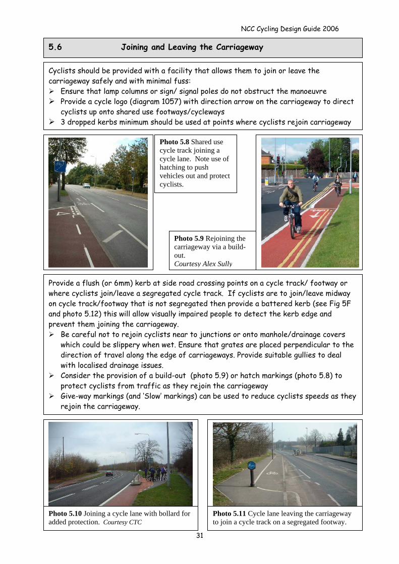
5.6 Joining and Leaving the Carriageway
Cyclists should be provided with a facility that allows them to join or leave the carriageway safely and with minimal fuss:
Ensure that lamp columns or sign/ signal poles do not obstruct the manoeuvre Provide a cycle logo (diagram 1057) with direction arrow on the carriageway to direct
cyclists up onto shared use footways/cycleways 3 dropped kerbs minimum should be used at points where cyclists rejoin carriageway
Photo 5.9 Rejoining the carriageway via a build-out. Courtesy Alex Sully
Photo 5.8 Shared use cycle track joining a cycle lane. Note use of hatching to push vehicles out and protect cyclists.
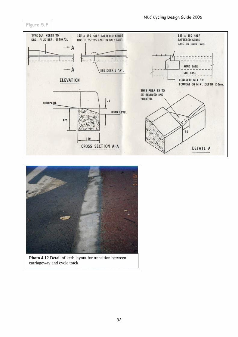
Provide a flush (or 6mm) kerb at side road crossing points on a cycle track/ footway or where cyclists join/leave a segregated cycle track. If cyclists are to join/leave midway on cycle track/footway that is not segregated then provide a battered kerb (see Fig 5F and photo 5.12) this will allow visually impaired people to detect the kerb edge and prevent them joining the carriageway.
Be careful not to rejoin cyclists near to junctions or onto manhole/drainage covers which could be slippery when wet. Ensure that grates are placed perpendicular to the direction of travel along the edge of carriageways. Provide suitable gullies to deal with localised drainage issues.
Consider the provision of a build-out (photo 5.9) or hatch markings (photo 5.8) to protect cyclists from traffic as they rejoin the carriageway
Give-way markings (and ‘Slow’ markings) can be used to reduce cyclists speeds as they rejoin the carriageway.
Photo 5.10 Joining a cycle lane with bollard for added protection. Courtesy CTC
Photo 5.11 Cycle lane leaving the carriageway to join a cycle track on a segregated footway.
NCC Cycling Design Guide 2006
Figure 5.F
Photo 4.12 Detail of kerb layout for transition between carriageway and cycle track
32
NCC Cycling Design Guide 2006
33
6.0 Signal Controlled Junctions and Crossings
6.1 Difficulties for Cyclists at Signal Controlled Junctions
Junctions and road crossings are dangerous parts of a cyclist’s route About 8% of cycling accidents in Nottinghamshire occur at signal controlled junctions
(accident data for the 3 years 2000-02) Major complex junctions can form a barrier to movement as cyclists can be fearful of
travelling through them Narrow lanes at stop lines (less than 3.0m) can result in cyclists being squeezed by traffic
It is possible with careful design to make junctions safer and more appealing for cyclists
6.2 General Design Principles
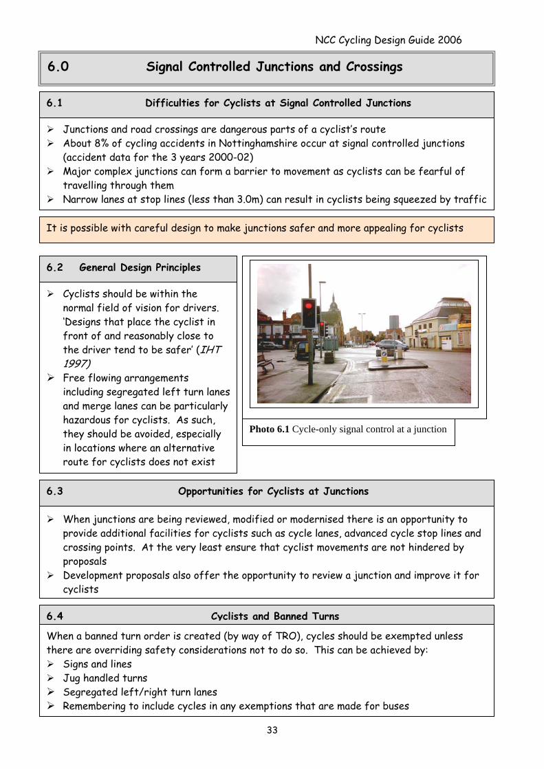
Cyclists should be within the normal field of vision for drivers. ‘Designs that place the cyclist in front of and reasonably close to the driver tend to be safer’ (IHT 1997)
Free flowing arrangements including segregated left turn lanes and merge lanes can be particularly hazardous for cyclists. As such, they should be avoided, especially in locations where an alternative route for cyclists does not exist
Photo 6.1 Cycle-only signal control at a junction
When junctions are being reviewed, modified or modernised there is an opportunity to provide additional facilities for cyclists such as cycle lanes, advanced cycle stop lines and crossing points. At the very least ensure that cyclist movements are not hindered by proposals
Development proposals also offer the opportunity to review a junction and improve it for cyclists
6.3 Opportunities for Cyclists at Junctions
6.4 Cyclists and Banned Turns
When a banned turn order is created (by way of TRO), cycles should be exempted unless there are overriding safety considerations not to do so. This can be achieved by:
Signs and lines Jug handled turns Segregated left/right turn lanes Remembering to include cycles in any exemptions that are made for buses
NCC Cycling Design Guide 2006
34
Cycle phases can be introduced at signal controlled junctions Cycle only stages can also be provided, when cyclists are provided with their own lane and
signals. These can be triggered by detectors, but it may be useful to provide a push button as well in case of failure to detect the cycle
Intergreens can be extended at wide junctions, to allow cyclists more time to safely clear the junction
Cycle crossing facilities can be incorporated into a junction and combined with pedestrian phases
Provide cycle lanes and Advanced Cycle Stoplines to help cyclists avoid queuing traffic. (see separate ASL Guide in Section 7)
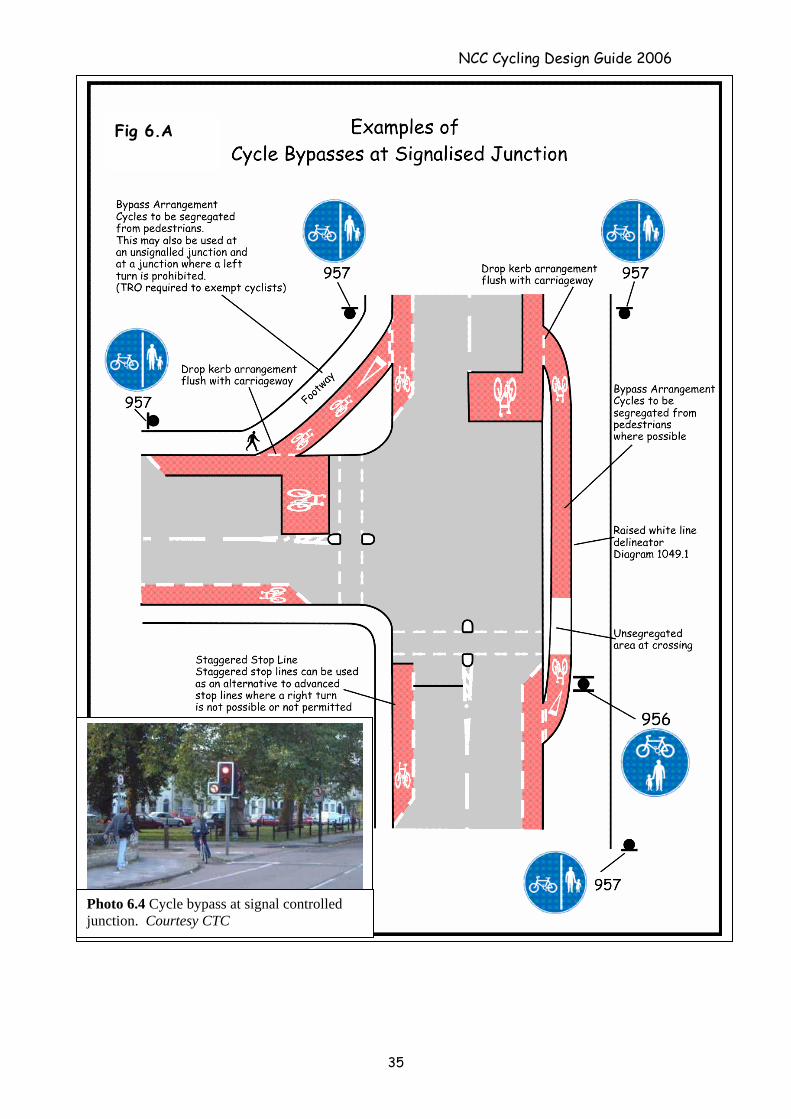
Provide cycle by-passes. Cyclists can be taken up onto a segregated shared use footway and can be provided with their own free-flow left turn or by pass for an unrestricted straight ahead movement (SEE FIGURE 6.A and photo 6.4)
6.5 Modifications for Cyclists at Signal Controlled Junctions
Cycle crossings facilities can be added to new and existing junctions and combined with pedestrian phases (see photo 5.6)
Provide a cycle aspect in addition to the ‘green man’ aspect Ensure that shared use signing is provided on the approaches and that clear direction
signing for cycling is included in the scheme
6.6 Signal Controlled Cycle Crossings
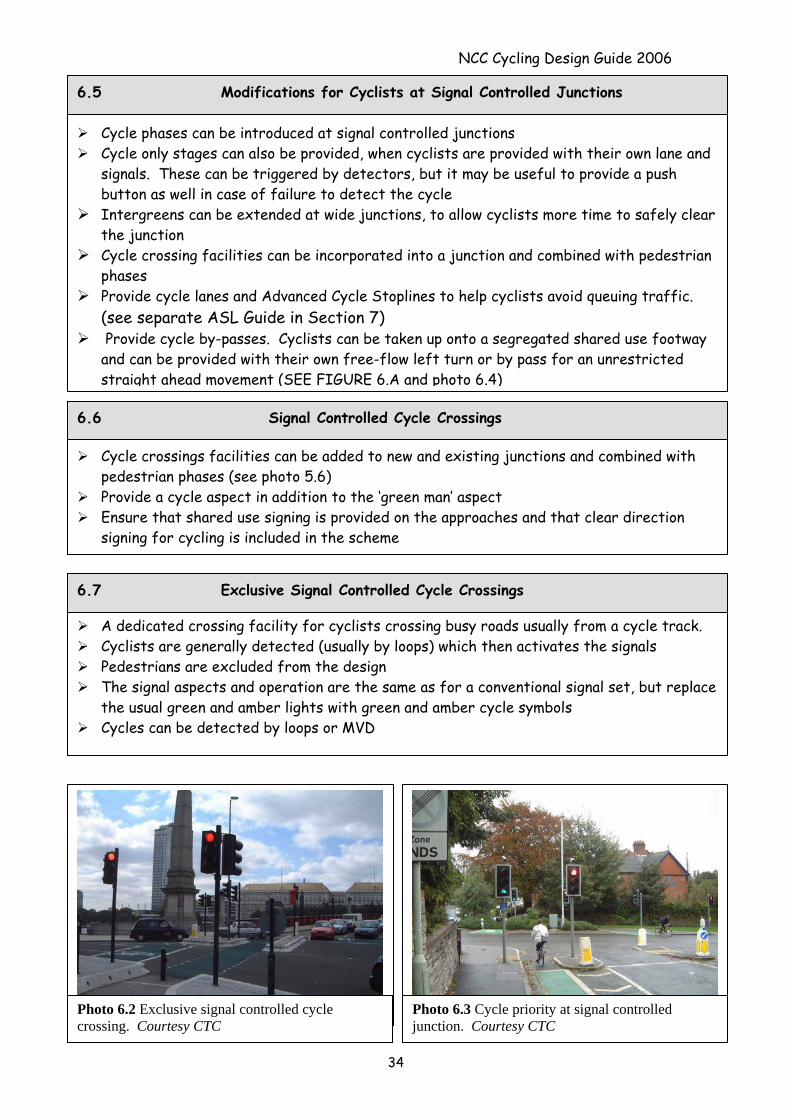
A dedicated crossing facility for cyclists crossing busy roads usually from a cycle track. Cyclists are generally detected (usually by loops) which then activates the signals Pedestrians are excluded from the design The signal aspects and operation are the same as for a conventional signal set, but replace
the usual green and amber lights with green and amber cycle symbols Cycles can be detected by loops or MVD
6.7 Exclusive Signal Controlled Cycle Crossings
Photo 6.2 Exclusive signal controlled cycle crossing. Courtesy CTC
Photo 6.3 Cycle priority at signal controlled junction. Courtesy CTC
NCC Cycling Design Guide 2006
35
Photo 6.4 Cycle bypass at signal controlled junction. Courtesy CTC
Fig 6.A
NCC Cycling Design Guide 2006
36
6.8 Parallel Cycle and Pedestrian Crossings
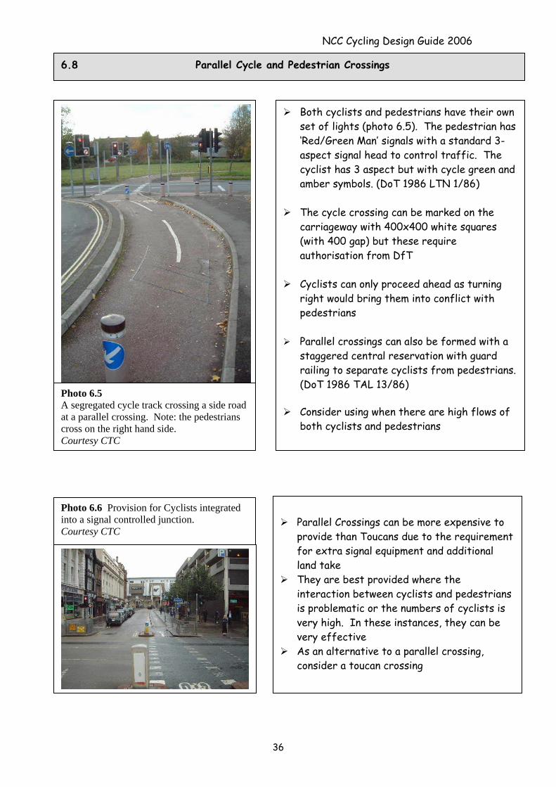
Photo 6.5 A segregated cycle track crossing a side road at a parallel crossing. Note: the pedestrians cross on the right hand side. Courtesy CTC
Both cyclists and pedestrians have their own set of lights (photo 6.5). The pedestrian has ‘Red/Green Man’ signals with a standard 3-aspect signal head to control traffic. The cyclist has 3 aspect but with cycle green and amber symbols. (DoT 1986 LTN 1/86)
The cycle crossing can be marked on the
carriageway with 400x400 white squares (with 400 gap) but these require authorisation from DfT
Cyclists can only proceed ahead as turning
right would bring them into conflict with pedestrians
Parallel crossings can also be formed with a
staggered central reservation with guard railing to separate cyclists from pedestrians. (DoT 1986 TAL 13/86)
Consider using when there are high flows of
both cyclists and pedestrians
Parallel Crossings can be more expensive to
provide than Toucans due to the requirement for extra signal equipment and additional land take
They are best provided where the interaction between cyclists and pedestrians is problematic or the numbers of cyclists is very high. In these instances, they can be very effective
As an alternative to a parallel crossing, consider a toucan crossing
Photo 6.6 Provision for Cyclists integrated into a signal controlled junction. Courtesy CTC
NCC Cycling Design Guide 2006
6.9 Toucan Crossings
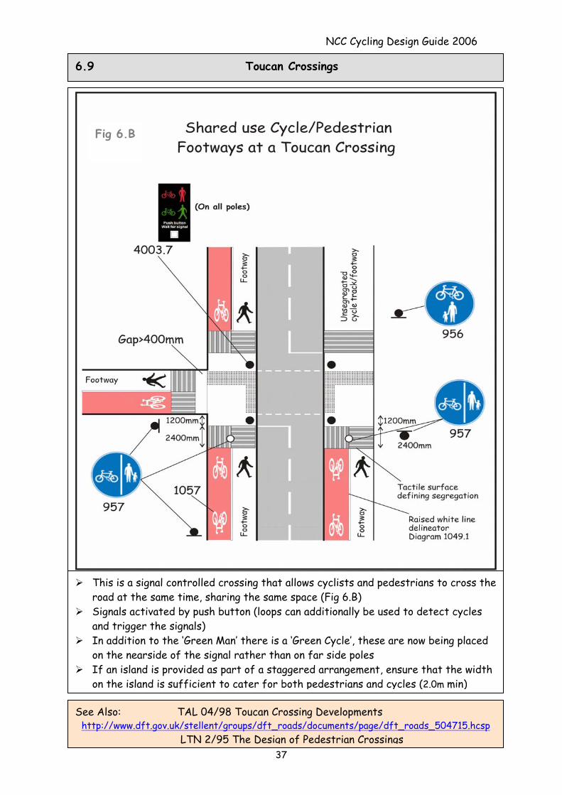
Fig 6.B
This is a signal controlled crossing that allows cyclists and pedestrians to cross the road at the same time, sharing the same space (Fig 6.B)
Signals activated by push button (loops can additionally be used to detect cycles and trigger the signals)
In addition to the ‘Green Man’ there is a ‘Green Cycle’, these are now being placed on the nearside of the signal rather than on far side poles
If an island is provided as part of a staggered arrangement, ensure that the width on the island is sufficient to cater for both pedestrians and cycles (2.0m min)
37
See Also: TAL 04/98 Toucan Crossing Developments http://www.dft.gov.uk/stellent/groups/dft_roads/documents/page/dft_roads_504715.hcsp
LTN 2/95 The Design of Pedestrian Crossings
NCC Cycling Design Guide 2006
7.0 Advanced Stop Lines (ASLs)
7.1 What is an Advanced Cycle Stop Line?
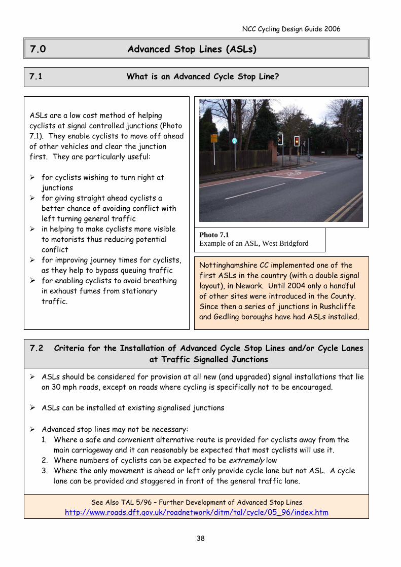
ASLs are a low cost method of helping cyclists at signal controlled junctions (Photo 7.1). They enable cyclists to move off ahead of other vehicles and clear the junction first. They are particularly useful:
for cyclists wishing to turn right at junctions
for giving straight ahead cyclists a better chance of avoiding conflict with left turning general traffic
in helping to make cyclists more visible to motorists thus reducing potential conflict
for improving journey times for cyclists, as they help to bypass queuing traffic
for enabling cyclists to avoid breathing in exhaust fumes from stationary traffic.
Photo 7.1 Example of an ASL, West Bridgford
Nottinghamshire CC implemented one of the first ASLs in the country (with a double signal layout), in Newark. Until 2004 only a handful of other sites were introduced in the County. Since then a series of junctions in Rushcliffe and Gedling boroughs have had ASLs installed.
ASLs should be considered for provision at all new (and upgraded) signal installations that lie on 30 mph roads, except on roads where cycling is specifically not to be encouraged.
ASLs can be installed at existing signalised junctions
Advanced stop lines may not be necessary:
1. Where a safe and convenient alternative route is provided for cyclists away from the main carriageway and it can reasonably be expected that most cyclists will use it.
2. Where numbers of cyclists can be expected to be extremely low 3. Where the only movement is ahead or left only provide cycle lane but not ASL. A cycle
lane can be provided and staggered in front of the general traffic lane.
See Also TAL 5/96 – Further Development of Advanced Stop Lines http://www.roads.dft.gov.uk/roadnetwork/ditm/tal/cycle/05_96/index.htm
7.2 Criteria for the Installation of Advanced Cycle Stop Lines and/or Cycle Lanes at Traffic Signalled Junctions
38
NCC Cycling Design Guide 2006
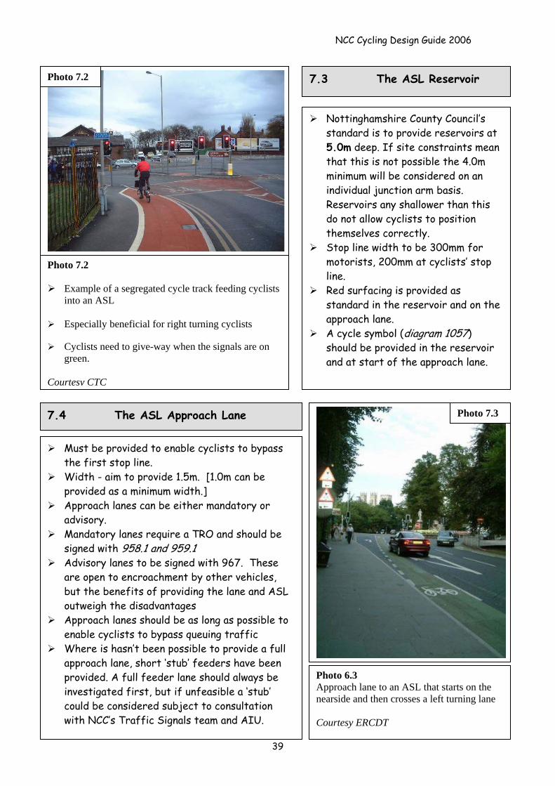
Photo 7.2
Example of a segregated cycle track feeding cyclists into an ASL
Especially beneficial for right turning cyclists
Cyclists need to give-way when the signals are on
green. Courtesy CTC
Photo 7.2 7.3 The ASL Reservoir
Nottinghamshire County Council’s standard is to provide reservoirs at 5.0m deep. If site constraints mean that this is not possible the 4.0m minimum will be considered on an individual junction arm basis. Reservoirs any shallower than this do not allow cyclists to position themselves correctly.
Stop line width to be 300mm for motorists, 200mm at cyclists’ stop line.
Red surfacing is provided as standard in the reservoir and on the approach lane.
A cycle symbol (diagram 1057) should be provided in the reservoir and at start of the approach lane.
7.4 The ASL Approach Lane Photo 7.3
Photo 6.3 Approach lane to an ASL that starts on the nearside and then crosses a left turning lane Courtesy ERCDT
39
Must be provided to enable cyclists to bypass the first stop line.
Width - aim to provide 1.5m. [1.0m can be provided as a minimum width.]
Approach lanes can be either mandatory or advisory.
Mandatory lanes require a TRO and should be signed with 958.1 and 959.1
Advisory lanes to be signed with 967. These are open to encroachment by other vehicles, but the benefits of providing the lane and ASL outweigh the disadvantages
Approach lanes should be as long as possible to enable cyclists to bypass queuing traffic
Where is hasn’t been possible to provide a full approach lane, short ‘stub’ feeders have been provided. A full feeder lane should always be investigated first, but if unfeasible a ‘stub’ could be considered subject to consultation with NCC’s Traffic Signals team and AIU.
NCC Cycling Design Guide 2006
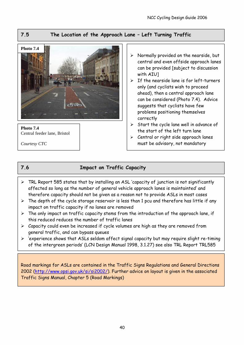
7.5 The Location of the Approach Lane – Left Turning Traffic
Photo 7.4 Normally provided on the nearside, but
central and even offside approach lanes can be provided [subject to discussion with AIU]
If the nearside lane is for left-turners only (and cyclists wish to proceed ahead), then a central approach lane can be considered (Photo 7.4). Advice suggests that cyclists have few problems positioning themselves correctly
Start the cycle lane well in advance of the start of the left turn lane
Central or right side approach lanes must be advisory, not mandatory
Photo 7.4 Central feeder lane, Bristol Courtesy CTC
7.6 Impact on Traffic Capacity
TRL Report 585 states that by installing an ASL ‘capacity of junction is not significantly affected so long as the number of general vehicle approach lanes is maintainted’ and therefore capacity should not be given as a reason not to provide ASLs in most cases
The depth of the cycle storage reservoir is less than 1 pcu and therefore has little if any impact on traffic capacity if no lanes are removed
The only impact on traffic capacity stems from the introduction of the approach lane, if this reduced reduces the number of traffic lanes
Capacity could even be increased if cycle volumes are high as they are removed from general traffic, and can bypass queues
‘experience shows that ASLs seldom affect signal capacity but may require slight re-timing of the intergreen periods’ (LCN Design Manual 1998, 3.1.27) see also TRL Report TRL585
Road markings for ASLs are contained in the Traffic Signs Regulations and General Directions 2002 (http://www.opsi.gov.uk/si/si2002/). Further advice on layout is given in the associated Traffic Signs Manual, Chapter 5 (Road Markings)
40
NCC Cycling Design Guide 2006
7.7 Case Study: West Bridgford, Nottingham
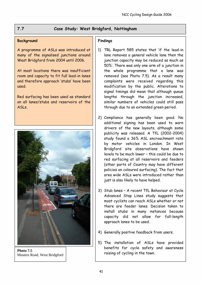
Background A programme of ASLs was introduced at many of the signalised junctions around West Bridgford from 2004 until 2006. At most locations there was insufficient room and capacity to fit full lead-in lanes and therefore approach ‘stubs’ have been used. Red surfacing has been used as standard on all lanes/stubs and reservoirs of the ASLs.
Findings 1) TRL Report 585 states that ‘if the lead-in
lane removes a general vehicle lane then the junction capacity may be reduced as much as 50%’. There was only one arm of a junction in the whole programme that a lane was removed (see Photo 7.5). As a result many complaints were received regarding this modification by the public. Alterations to signal timings did mean that although queue lengths through the junction increased, similar numbers of vehicles could still pass through due to an extended green period.
2) Compliance has generally been good. No
additional signing has been used to warn drivers of the new layouts, although some publicity was released. A TfL (2002-2004) study found a 36% ASL encroachment rate by motor vehicles in London. In West Bridgford site observations have shown levels to be much lower – this could be due to red surfacing at all reservoirs and feeders (other parts of Country may have different policies on coloured surfacing). The fact that area wide ASLs were introduced rather than just is also likely to have helped.
3) Stub lanes – A recent TfL Behaviour at Cycle
Advanced Stop Lines study suggests that most cyclists can reach ASLs whether or not there are feeder lanes. Decision taken to install stubs in many instances because capacity did not allow for full-length approach lanes to be used.
4) Generally positive feedback from users. 5) The installation of ASLs have provided
benefits for cycle safety and awareness raising of cycling in the town.
Photo 7.5 Musters Road, West Bridgford
41
NCC Cycling Design Guide 2006
8.0 Cyclists and Roundabouts
Roundabouts, and in particular, large roundabouts can be a feared feature of the road network for cyclists. Some cyclists may change their route, or even divert to another mode of travel because of their desire to avoid travelling through roundabouts.
There is good reason for the cyclists’ fear as they are generally over represented in accidents at roundabouts. Between 1999-2001 7% of all cycle accidents in the County occurred at roundabouts.
Roundabouts with flared entries and large roundabouts that allow high speeds are particularly hazardous.
The greater the number of arms, then the greater the problem. The majority of accidents (50%) involving cyclists on roundabouts occur when a cyclist on
the roundabout is struck by a vehicle entering the roundabout (TRL Report 285). There appears to be some failure or inability of drivers to see circulating cyclists.
Another common type of accident for cyclists using roundabouts is when a cyclist, crossing one of the exits from the roundabout and continuing around the roundabout, is hit by a motor vehicle exiting the roundabout.
8.1 Why are Roundabouts a Problem for Cyclists?
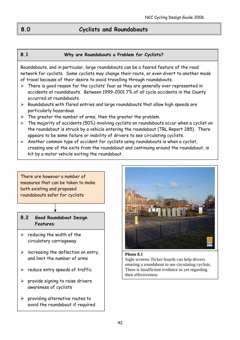
Photo 8.1 Sight screens/ flicker boards can help drivers entering a roundabout to see circulating cyclists. There is insufficient evidence as yet regarding their effectiveness
There are however a number of measures that can be taken to make both existing and proposed roundabouts safer for cyclists
reducing the width of the circulatory carriageway
increasing the deflection on entry,
and limit the number of arms
reduce entry speeds of traffic
provide signing to raise drivers awareness of cyclists
providing alternative routes to
avoid the roundabout if required
8.2 Good Roundabout Design Features:
42
NCC Cycling Design Guide 2006
43
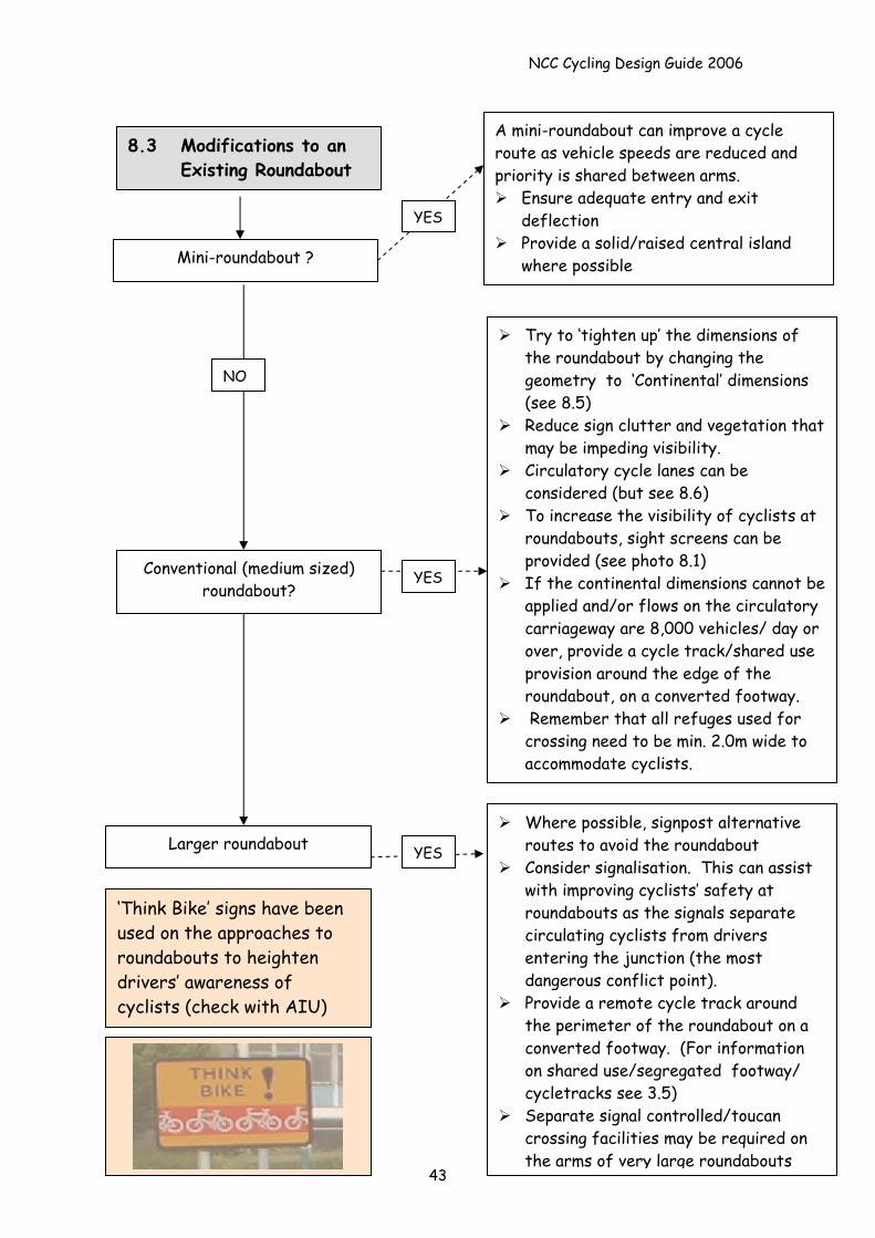
8.3 Modifications to an Existing Roundabout
Mini-roundabout ?
Conventional (medium sized) roundabout?
Larger roundabout
YES
YES
YES
‘Think Bike’ signs have been used on the approaches to roundabouts to heighten drivers’ awareness of cyclists (check with AIU)
NO
Where possible, signpost alternative routes to avoid the roundabout
Consider signalisation. This can assist with improving cyclists’ safety at roundabouts as the signals separate circulating cyclists from drivers entering the junction (the most dangerous conflict point).
Provide a remote cycle track around the perimeter of the roundabout on a converted footway. (For information on shared use/segregated footway/ cycletracks see 3.5)
Separate signal controlled/toucan crossing facilities may be required on the arms of very large roundabouts
Try to ‘tighten up’ the dimensions of the roundabout by changing the geometry to ‘Continental’ dimensions (see 8.5)
Reduce sign clutter and vegetation that may be impeding visibility.
Circulatory cycle lanes can be considered (but see 8.6)
To increase the visibility of cyclists at roundabouts, sight screens can be provided (see photo 8.1)
If the continental dimensions cannot be applied and/or flows on the circulatory carriageway are 8,000 vehicles/ day or over, provide a cycle track/shared use provision around the edge of the roundabout, on a converted footway.
Remember that all refuges used for crossing need to be min. 2.0m wide to accommodate cyclists.
A mini-roundabout can improve a cycle route as vehicle speeds are reduced and priority is shared between arms.
Ensure adequate entry and exit deflection
Provide a solid/raised central island where possible
NCC Cycling Design Guide 2006
44
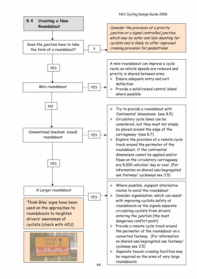
8.4 Creating a New Roundabout
?
Consider the provision of a priority junction or a signal controlled junction, which may be safer and less daunting for cyclists and is likely to offer improved crossing provision for pedestrians
Does the junction have to take the form of a roundabout?
YES
YES
Conventional (medium sized) roundabout
A Larger roundabout Where possible, signpost alternative
routes to avoid the roundabout Consider signalisation, which can assist
with improving cyclists safety at roundabouts as the signals separate circulating cyclists from drivers entering the junction (the most dangerous conflict point)
Provide a remote cycle track around the perimeter of the roundabout on a converted footway. (For information on shared use/segregated use footway/ cycleway see 3.5)
Separate toucan crossing facilities may be required on the arms of very large roundabouts
YES‘Think Bike’ signs have been used on the approaches to roundabouts to heighten drivers’ awareness of cyclists (check with AIU)
NO
YES
Try to provide a roundabout with ‘Continental’ dimensions (see 8.5)
Circulatory cycle lanes can be considered, but they must not simply be placed around the edge of the carriageway –(see 8.7)
Explore the provision of a remote cycle track around the perimeter of the roundabout, if the continental dimensions cannot be applied and/or flows on the circulatory carriageway are 8,000 vehicles/ day or over. (For information on shared use/segregated use footway/ cycleways see 3.5)
Mini-roundabout
A mini-roundabout can improve a cycle route as vehicle speeds are reduced and priority is shared between arms.
Ensure adequate entry and exit deflection
Provide a solid/raised central island where possible
YES
NCC Cycling Design Guide 2006
45
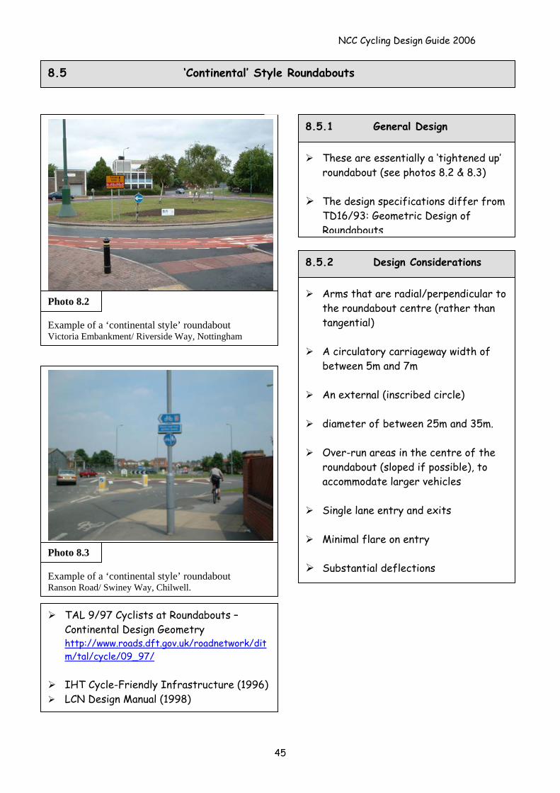
8.5 ‘Continental’ Style Roundabouts
Arms that are radial/perpendicular to the roundabout centre (rather than tangential)
A circulatory carriageway width of
between 5m and 7m
An external (inscribed circle)
diameter of between 25m and 35m.
Over-run areas in the centre of the roundabout (sloped if possible), to accommodate larger vehicles
Single lane entry and exits
Minimal flare on entry
Substantial deflections
These are essentially a ‘tightened up’ roundabout (see photos 8.2 & 8.3)
The design specifications differ from
TD16/93: Geometric Design of Roundabouts
8.5.2 Design Considerations
8.5.1 General Design
Example of a ‘continental style’ roundabout Victoria Embankment/ Riverside Way, Nottingham
Photo 8.2
Example of a ‘continental style’ roundabout Ranson Road/ Swiney Way, Chilwell.
Photo 8.3
TAL 9/97 Cyclists at Roundabouts – Continental Design Geometry http://www.roads.dft.gov.uk/roadnetwork/ditm/tal/cycle/09_97/
IHT Cycle-Friendly Infrastructure (1996) LCN Design Manual (1998)
NCC Cycling Design Guide 2006
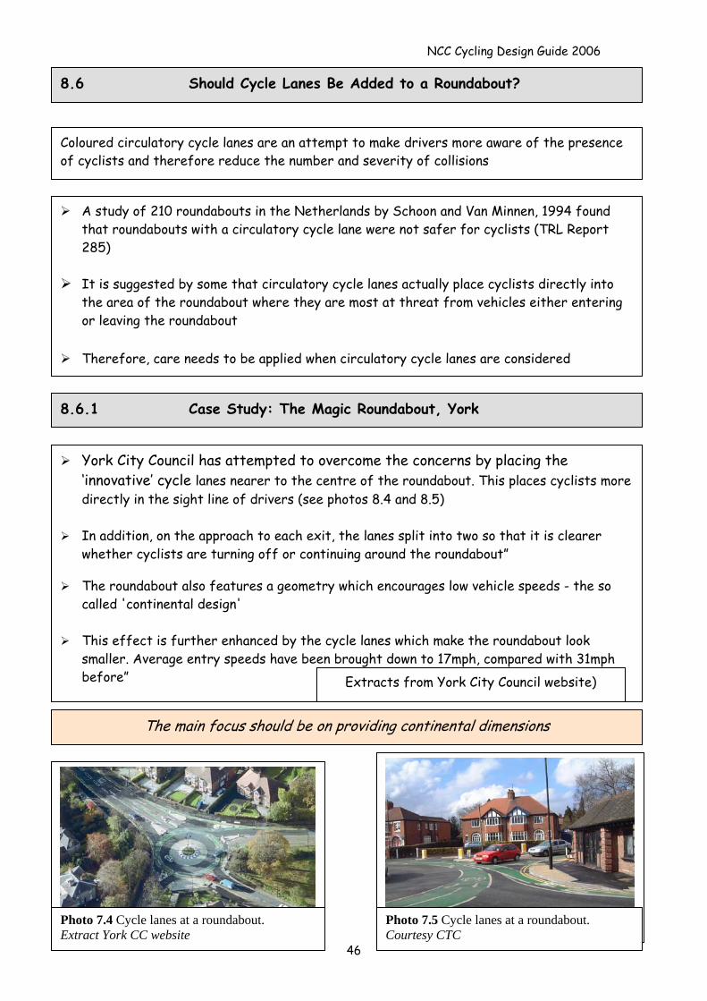
8.6 Should Cycle Lanes Be Added to a Roundabout?
Coloured circulatory cycle lanes are an attempt to make drivers more aware of the presence of cyclists and therefore reduce the number and severity of collisions
A study of 210 roundabouts in the Netherlands by Schoon and Van Minnen, 1994 found that roundabouts with a circulatory cycle lane were not safer for cyclists (TRL Report 285)
It is suggested by some that circulatory cycle lanes actually place cyclists directly into
the area of the roundabout where they are most at threat from vehicles either entering or leaving the roundabout
Therefore, care needs to be applied when circulatory cycle lanes are considered
8.6.1 Case Study: The Magic Roundabout, York
York City Council has attempted to overcome the concerns by placing the ‘innovative’ cycle lanes nearer to the centre of the roundabout. This places cyclists more directly in the sight line of drivers (see photos 8.4 and 8.5)
In addition, on the approach to each exit, the lanes split into two so that it is clearer
whether cyclists are turning off or continuing around the roundabout”
The roundabout also features a geometry which encourages low vehicle speeds - the so called 'continental design'
This effect is further enhanced by the cycle lanes which make the roundabout look
smaller. Average entry speeds have been brought down to 17mph, compared with 31mph before” Extracts from York City Council website)
The main focus should be on providing continental dimensions
Photo 7.5 Cycle lanes at a roundabout. Courtesy CTC
Photo 7.4 Cycle lanes at a roundabout. Extract York CC website
46
NCC Cycling Design Guide 2006
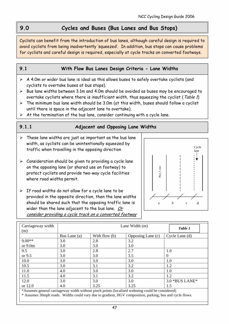
9.0 Cycles and Buses (Bus Lanes and Bus Stops)
Cyclists can benefit from the introduction of bus lanes, although careful design is required to avoid cyclists from being inadvertently ‘squeezed’. In addition, bus stops can cause problems for cyclists and careful design is required, especially at cycle tracks on converted footways.
9.1 With Flow Bus Lanes Design Criteria - Lane Widths
Carriageway width (m)
Lane Width (m)
Bus Lane (a) With flow (b) Opposing Lane (c) Cycle Lane (d) 9.00** or 9.0m
3.0 3.0
2.8 3.0
3.2 3.0
9.5 or 9.5
3.0 3.0
2.8 3.0
2.7 3.5
1.0 0
10.0 3.0 3.0 3.0 1.0 10.5 3.0 3.1 3.2 1.2 11.0 4.0 3.0 3.0 1.0 11.5 4.0 3.1 3.2 1.2 12.0 or 12.0
3.0 4.0
3.0 3.25
3.0 3.25
3.0 *BUS LANE* 1.5
*Assumes general carriageway width without pinch points (localised widening could be considered) * Assumes 30mph roads. Widths could vary due to gradient, HGV composition, parking, bus and cycle flows.
A 4.0m or wider bus lane is ideal as this allows buses to safely overtake cyclists (and cyclists to overtake buses at bus stops).
Bus lane widths between 3.1m and 4.0m should be avoided as buses may be encouraged to overtake cyclists where there is insufficient width, thus squeezing the cyclist (Table 1)
The minimum bus lane width should be 3.0m (at this width, buses should follow a cyclist until there is space in the adjacent lane to overtake).
At the termination of the bus lane, consider continuing with a cycle lane.
These lane widths are just as important as the bus lane width, as cyclists can be unintentionally squeezed by traffic when travelling in the opposing direction
Consideration should be given to providing a cycle lane
on the opposing lane (or shared use on footway) to protect cyclists and provide two-way cycle facilities where road widths permit.
If road widths do not allow for a cycle lane to be
provided in the opposite direction, then the lane widths should be shared such that the opposing traffic lane is wider than the lane adjacent to the bus lane. Or consider providing a cycle track on a converted footway
9.1.1 Adjacent and Opposing Lane Widths
Bus
Lane
Cycle lane
a b c d
Table 1
47
NCC Cycling Design Guide 2006
48
9.2 Contra-Flow Bus Lanes
Cyclists should be able to use contra flow bus lanes although particular attention needs to be paid to:
Whether the cyclist can enter and leave the lane safely including the consideration of signal control at junctions at both ends of the contra-flow lane
The danger of buses leaving the confines of an unsegregated contra-flow lane to overtake a cyclist
Safety for cyclists at side road junctions
9.2.1 Contra-Flow Bus Lane Widths
Where no physical separation is provided such as barriers, islands then a 3.2m lane is acceptable for short lengths (4.0m is preferred)
Where physical separation exists, try to provide 4.0m, unless cycle numbers are extremely low
9.3 Bus Only Turns and Bus Only Streets
Cyclists should be permitted to make all manoeuvres that buses can unless there are overriding safety implications of allowing this
A cycle by-pass should be provided at the entrance to a bus only street that is signed as ‘no-entry except buses’
Photo 9.1 Bus and Cycle Lane with additional unsegregated shared path/ cycle track on a converted footway (note blue 956 sign).
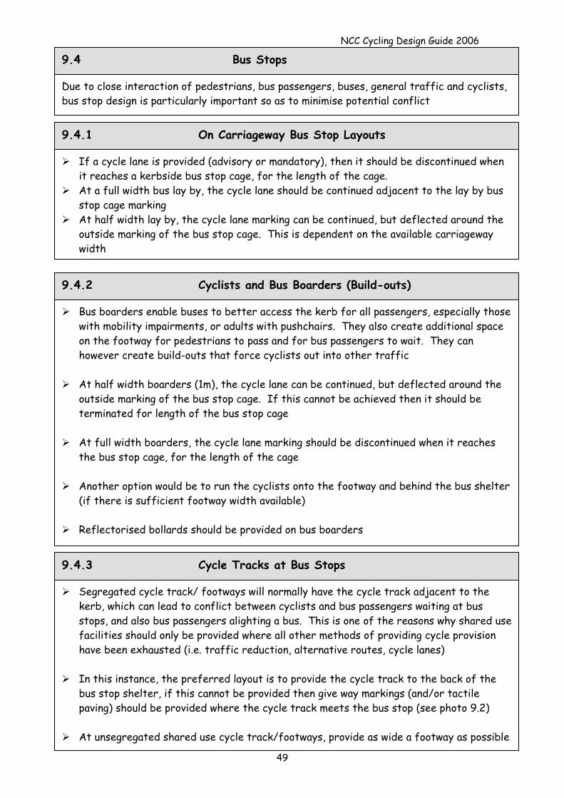
NCC Cycling Design Guide 2006
Due to close interaction of pedestrians, bus passengers, buses, general traffic and cyclists, bus stop design is particularly important so as to minimise potential conflict
9.4 Bus Stops
9.4.1 On Carriageway Bus Stop Layouts
If a cycle lane is provided (advisory or mandatory), then it should be discontinued when it reaches a kerbside bus stop cage, for the length of the cage.
At a full width bus lay by, the cycle lane should be continued adjacent to the lay by bus stop cage marking
At half width lay by, the cycle lane marking can be continued, but deflected around the outside marking of the bus stop cage. This is dependent on the available carriageway width
49
9.4.2 Cyclists and Bus Boarders (Build-outs)
Bus boarders enable buses to better access the kerb for all passengers, especially those with mobility impairments, or adults with pushchairs. They also create additional space on the footway for pedestrians to pass and for bus passengers to wait. They can however create build-outs that force cyclists out into other traffic
At half width boarders (1m), the cycle lane can be continued, but deflected around the
outside marking of the bus stop cage. If this cannot be achieved then it should be terminated for length of the bus stop cage
At full width boarders, the cycle lane marking should be discontinued when it reaches
the bus stop cage, for the length of the cage
Another option would be to run the cyclists onto the footway and behind the bus shelter (if there is sufficient footway width available)
Reflectorised bollards should be provided on bus boarders
Segregated cycle track/ footways will normally have the cycle track adjacent to the kerb, which can lead to conflict between cyclists and bus passengers waiting at bus stops, and also bus passengers alighting a bus. This is one of the reasons why shared use facilities should only be provided where all other methods of providing cycle provision have been exhausted (i.e. traffic reduction, alternative routes, cycle lanes)
In this instance, the preferred layout is to provide the cycle track to the back of the
bus stop shelter, if this cannot be provided then give way markings (and/or tactile paving) should be provided where the cycle track meets the bus stop (see photo 9.2)
At unsegregated shared use cycle track/footways, provide as wide a footway as possible
9.4.3 Cycle Tracks at Bus Stops
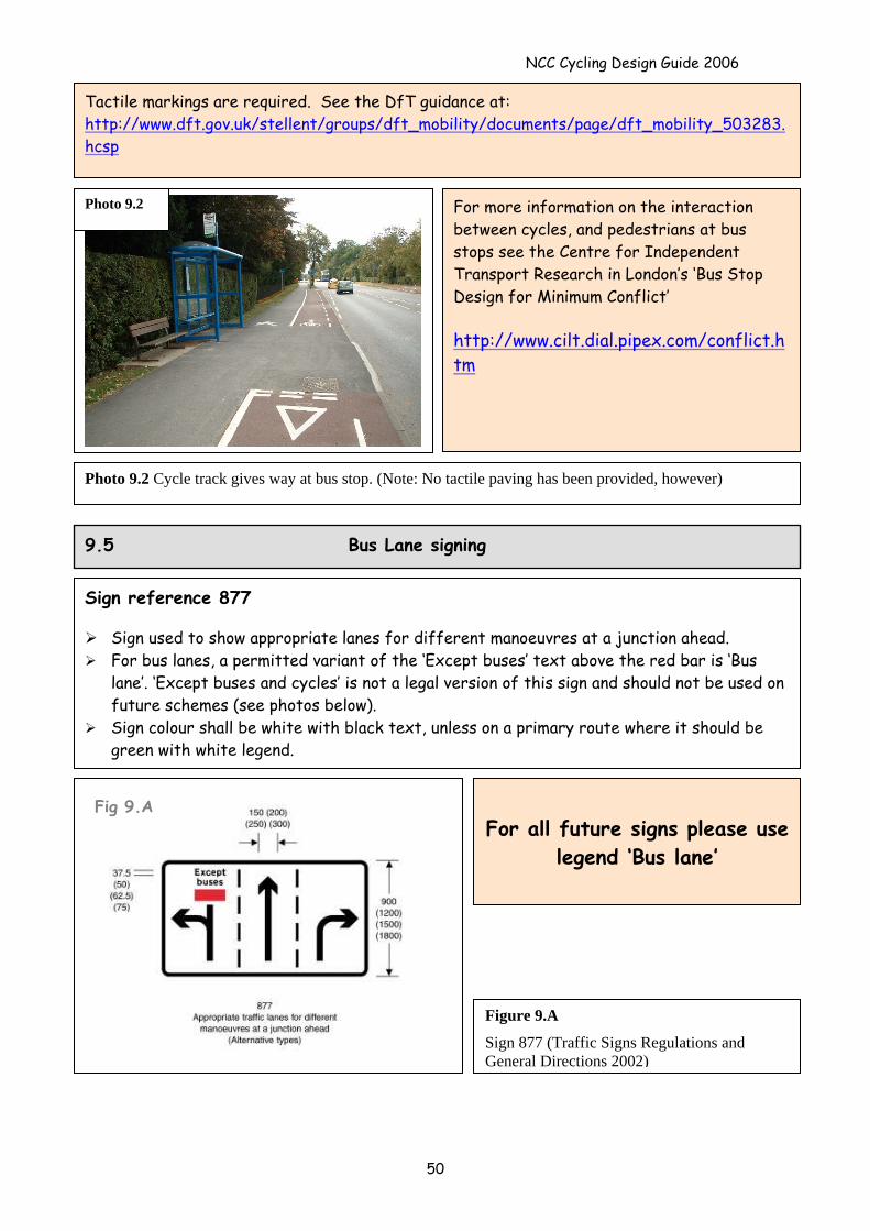
NCC Cycling Design Guide 2006
Photo 9.2 Cycle track gives way at bus stop. (Note: No tactile paving has been provided, however)
For more information on the interaction between cycles, and pedestrians at bus stops see the Centre for Independent Transport Research in London’s ‘Bus Stop Design for Minimum Conflict’ http://www.cilt.dial.pipex.com/conflict.htm
Tactile markings are required. See the DfT guidance at: http://www.dft.gov.uk/stellent/groups/dft_mobility/documents/page/dft_mobility_503283.hcsp
9.5 Bus Lane signing
Sign reference 877
Sign used to show appropriate lanes for different manoeuvres at a junction ahead. For bus lanes, a permitted variant of the ‘Except buses’ text above the red bar is ‘Bus
lane’. ‘Except buses and cycles’ is not a legal version of this sign and should not be used on future schemes (see photos below).
Sign colour shall be white with black text, unless on a primary route where it should be green with white legend.
Fig 9.A
Photo 9.2
For all future signs please use
legend ‘Bus lane’
Figure 9.A
Sign 877 (Traffic Signs Regulations and General Directions 2002)
50
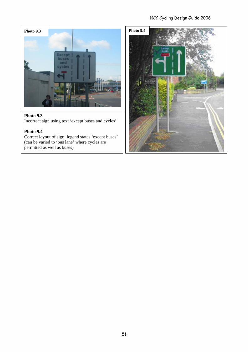
NCC Cycling Design Guide 2006
Photo 9.4Photo 9.3
Photo 9.3 Incorrect sign using text ‘except buses and cycles’ Photo 9.4 Correct layout of sign; legend states ‘except buses’ (can be varied to ‘bus lane’ where cycles are permitted as well as buses)
51
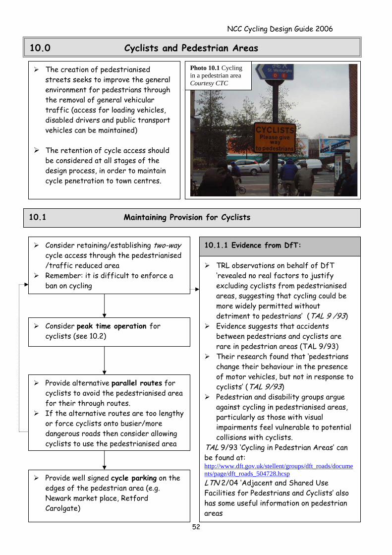
NCC Cycling Design Guide 2006
10.0 Cyclists and Pedestrian Areas
The creation of pedestrianised streets seeks to improve the general environment for pedestrians through the removal of general vehicular traffic (access for loading vehicles, disabled drivers and public transport vehicles can be maintained)
The retention of cycle access should
be considered at all stages of the design process, in order to maintain cycle penetration to town centres.
Photo 10.1 Cycling in a pedestrian area Courtesy CTC
10.1 Maintaining Provision for Cyclists
52
Consider retaining/establishing two-way cycle access through the pedestrianised /traffic reduced area
Remember: it is difficult to enforce a ban on cycling
Consider peak time operation for cyclists (see 10.2)
Provide alternative parallel routes for cyclists to avoid the pedestrianised area for their through routes.
If the alternative routes are too lengthy or force cyclists onto busier/more dangerous roads then consider allowing cyclists to use the pedestrianised area
TRL observations on behalf of DfT ‘revealed no real factors to justify excluding cyclists from pedestrianised areas, suggesting that cycling could be more widely permitted without detriment to pedestrians’ (TAL 9 /93)
Evidence suggests that accidents between pedestrians and cyclists are rare in pedestrian areas (TAL 9/93)
Their research found that ‘pedestrians change their behaviour in the presence of motor vehicles, but not in response to cyclists’ (TAL 9/93)
Pedestrian and disability groups argue against cycling in pedestrianised areas, particularly as those with visual impairments feel vulnerable to potential collisions with cyclists.
TAL 9/93 ‘Cycling in Pedestrian Areas’ can be found at: http://www.dft.gov.uk/stellent/groups/dft_roads/documents/page/dft_roads_504728.hcsp LTN 2/04 ‘Adjacent and Shared Use Facilities for Pedestrians and Cyclists’ also has some useful information on pedestrian areas
10.1.1 Evidence from DfT:
Provide well signed cycle parking on the edges of the pedestrian area (e.g. Newark market place, Retford Carolgate)
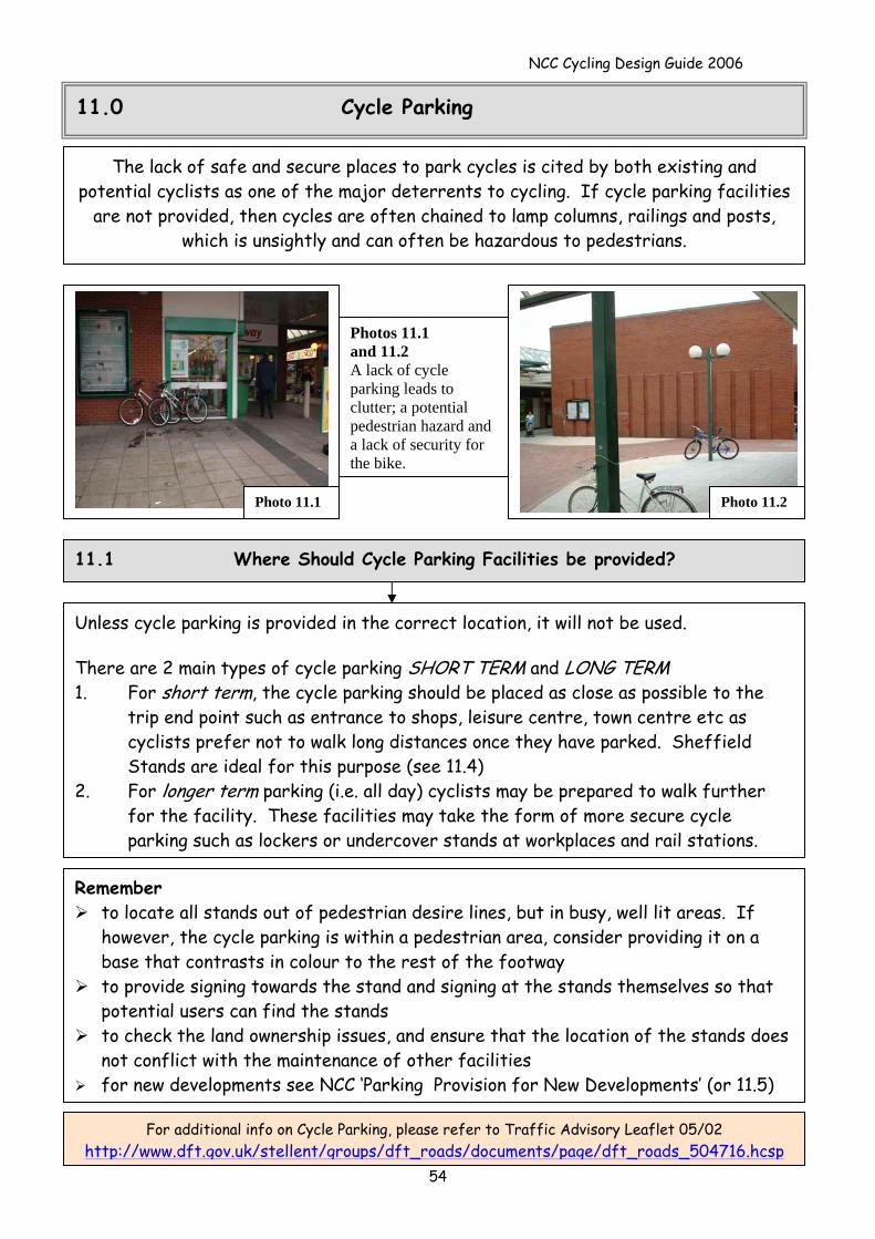
NCC Cycling Design Guide 2006
11.0 Cycle Parking
The lack of safe and secure places to park cycles is cited by both existing and potential cyclists as one of the major deterrents to cycling. If cycle parking facilities
are not provided, then cycles are often chained to lamp columns, railings and posts, which is unsightly and can often be hazardous to pedestrians.
54
Unless cycle parking is provided in the correct location, it will not be used. There are 2 main types of cycle parking SHORT TERM and LONG TERM 1. For short term, the cycle parking should be placed as close as possible to the
trip end point such as entrance to shops, leisure centre, town centre etc as cyclists prefer not to walk long distances once they have parked. Sheffield Stands are ideal for this purpose (see 11.4)
2. For longer term parking (i.e. all day) cyclists may be prepared to walk further for the facility. These facilities may take the form of more secure cycle parking such as lockers or undercover stands at workplaces and rail stations.
For additional info on Cycle Parking, please refer to Traffic Advisory Leaflet 05/02 http://www.dft.gov.uk/stellent/groups/dft_roads/documents/page/dft_roads_504716.hcsp
Remember to locate all stands out of pedestrian desire lines, but in busy, well lit areas. If
however, the cycle parking is within a pedestrian area, consider providing it on a base that contrasts in colour to the rest of the footway
to provide signing towards the stand and signing at the stands themselves so that potential users can find the stands
to check the land ownership issues, and ensure that the location of the stands does not conflict with the maintenance of other facilities
for new developments see NCC ‘Parking Provision for New Developments’ (or 11.5)
11.1 Where Should Cycle Parking Facilities be provided?
Photo 10.2
Photo 11.2 Photo 11.1
Photos 11.1 and 11.2 A lack of cycle parking leads to clutter; a potential pedestrian hazard and a lack of security for the bike.
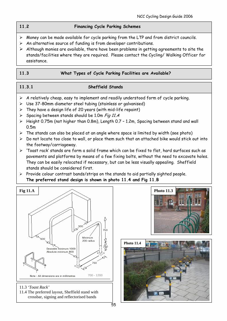
NCC Cycling Design Guide 2006
11.2 Financing Cycle Parking Schemes
Money can be made available for cycle parking from the LTP and from district councils. An alternative source of funding is from developer contributions. Although monies are available, there have been problems in getting agreements to site the
stands/facilities where they are required. Please contact the Cycling/ Walking Officer for assistance.
11.3 What Types of Cycle Parking Facilities are Available?
11.3.1 Sheffield Stands
A relatively cheap, easy to implement and readily understood form of cycle parking. Use 37-80mm diameter steel tubing (stainless or galvanised) They have a design life of 20 years (with mid-life repaint) Spacing between stands should be 1.0m Fig 11.A Height 0.75m (not higher than 0.8m), Length 0.7 – 1.2m, Spacing between stand and wall
0.5m The stands can also be placed at an angle where space is limited by width (see photo) Do not locate too close to wall, or place them such that an attached bike would stick out into
the footway/carriageway. ‘Toast rack’ stands are form a solid frame which can be fixed to flat, hard surfaces such as
pavements and platforms by means of a few fixing bolts, without the need to excavate holes. They can be easily relocated if necessary, but can be less visually appealing. Sheffield stands should be considered first.
Provide colour contrast bands/strips on the stands to aid partially sighted people. The preferred stand design is shown in photo 11.4 and Fig 11.B
Fig 11.A
700 - 1200
Photo 11.3
Photo 11.4
55
11.3 ‘Toast Rack’ 11.4 The preferred layout, Sheffield stand with crossbar, signing and reflectorised bands
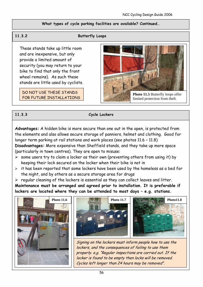
NCC Cycling Design Guide 2006
What types of cycle parking facilities are available? Continued…
These stands take up little room and are inexpensive, but only provide a limited amount of security (you may return to your bike to find that only the front wheel remains). As such these stands are little used by cyclists.
DO NOT USE THESE STANDS FOR FUTURE INSTALLATIONS
Photo 11.5 Butterfly loops offer limited protection from theft.
11.3.2 Butterfly Loops
56
11.3.3 Cycle Lockers
Advantages: A hidden bike is more secure than one out in the open, is protected from the elements and also allows secure storage of panniers, helmet and clothing. Good for longer term parking at rail stations and work places (see photos 11.6 – 11.8) Disadvantages: More expensive than Sheffield stands, and they take up more space (particularly in town centres). They are open to misuse:
some users try to claim a locker as their own (preventing others from using it) by keeping their lock secured on the locker when their bike is not in
it has been reported that some lockers have been used by the homeless as a bed for the night, and by others as a secure storage area for drugs
regular cleaning of the lockers is essential as they can collect leaves and litter. Maintenance must be arranged and agreed prior to installation. It is preferable if lockers are located where they can be attended to most days – e.g. stations.
Photo 11.6 Photo 11.7 Photo11.8
Signing on the lockers must inform people how to use the lockers, and the consequences of failing to use them properly. e.g. “Regular inspections are carried out. If the locker is found to be empty then locks will be removed. Cycles left longer than 24 hours may be removed”.
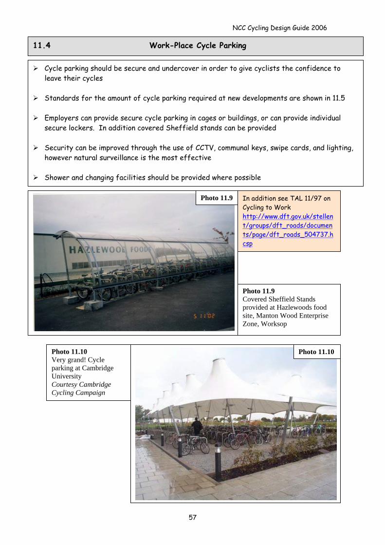
NCC Cycling Design Guide 2006
57
11.4 Work-Place Cycle Parking
Cycle parking should be secure and undercover in order to give cyclists the confidence to leave their cycles
Standards for the amount of cycle parking required at new developments are shown in 11.5
Employers can provide secure cycle parking in cages or buildings, or can provide individual
secure lockers. In addition covered Sheffield stands can be provided
Security can be improved through the use of CCTV, communal keys, swipe cards, and lighting, however natural surveillance is the most effective
Shower and changing facilities should be provided where possible
Photo 11.9 In addition see TAL 11/97 on Cycling to Work http://www.dft.gov.uk/stellent/groups/dft_roads/documents/page/dft_roads_504737.hcsp
Photo 11.9 Covered Sheffield Stands provided at Hazlewoods food site, Manton Wood Enterprise Zone, Worksop
Photo 11.10 Very grand! Cycle parking at Cambridge University Courtesy Cambridge Cycling Campaign
Photo 11.10
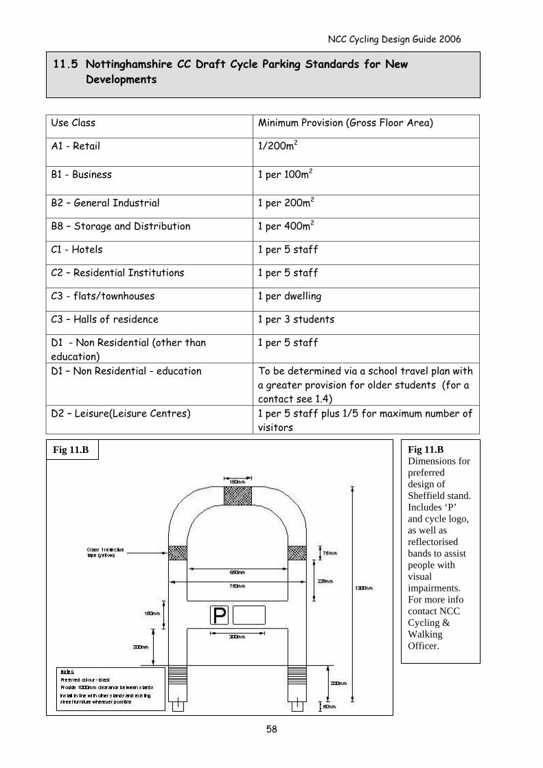
NCC Cycling Design Guide 2006
11.5 Nottinghamshire CC Draft Cycle Parking Standards for New Developments
58
Use Class Minimum Provision (Gross Floor Area)
A1 - Retail 1/200m2
B1 - Business 1 per 100m2
B2 – General Industrial 1 per 200m2
B8 – Storage and Distribution 1 per 400m2
C1 - Hotels 1 per 5 staff
C2 – Residential Institutions 1 per 5 staff
C3 - flats/townhouses 1 per dwelling
C3 – Halls of residence 1 per 3 students
D1 - Non Residential (other than education)
1 per 5 staff
D1 – Non Residential - education To be determined via a school travel plan with a greater provision for older students (for a contact see 1.4)
D2 – Leisure(Leisure Centres) 1 per 5 staff plus 1/5 for maximum number of visitors
Fig 11.B Dimensions for preferred design of Sheffield stand. Includes ‘P’ and cycle logo, as well as reflectorised bands to assist people with visual impairments. For more info contact NCC Cycling & Walking Officer.
Fig 11.B
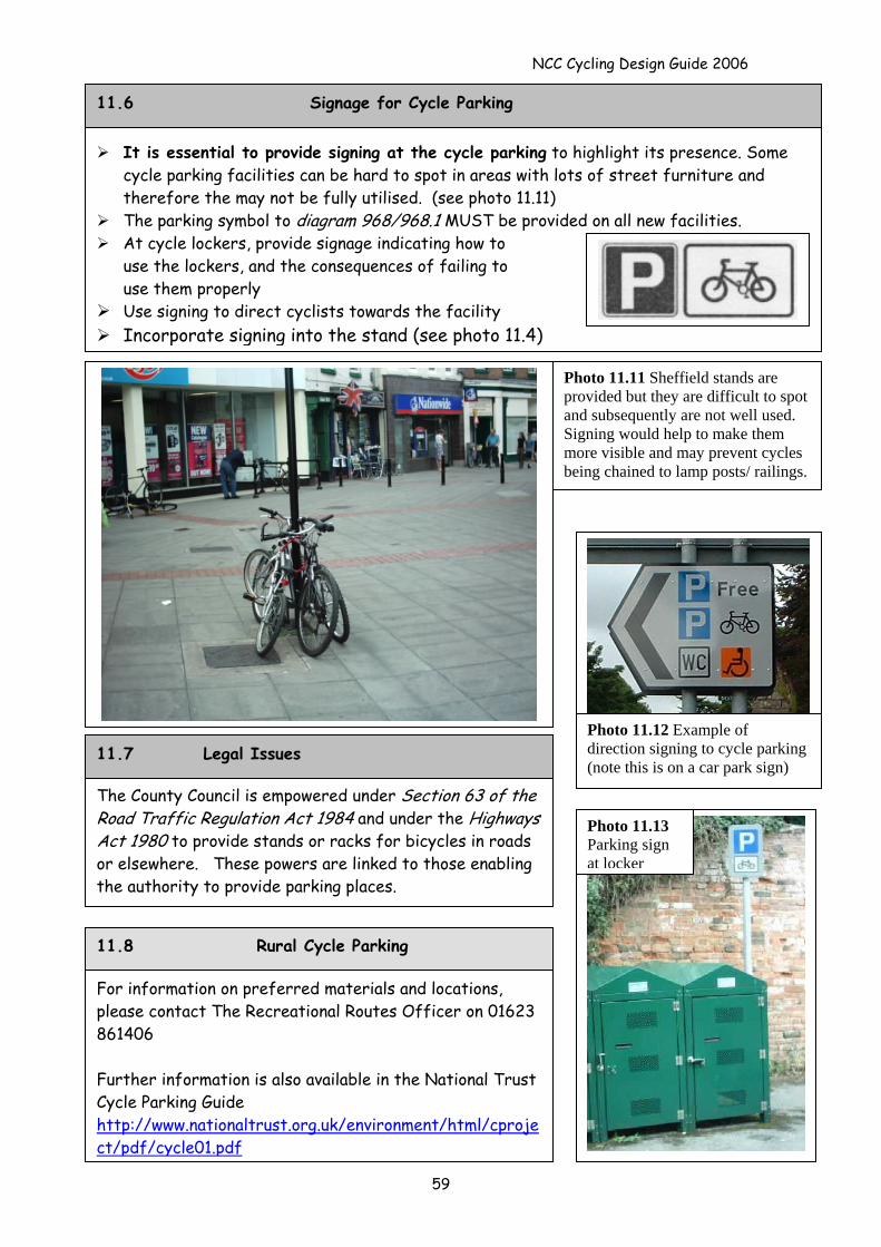
NCC Cycling Design Guide 2006
The County Council is empowered under Section 63 of the Road Traffic Regulation Act 1984 and under the Highways Act 1980 to provide stands or racks for bicycles in roads or elsewhere. These powers are linked to those enabling the authority to provide parking places.
For information on preferred materials and locations, please contact The Recreational Routes Officer on 01623 861406 Further information is also available in the National Trust Cycle Parking Guide http://www.nationaltrust.org.uk/environment/html/cproject/pdf/cycle01.pdf
11.8 Rural Cycle Parking
11.7 Legal Issues
Photo 11.13 Parking sign at locker
Photo 11.11 Sheffield stands are provided but they are difficult to spot and subsequently are not well used. Signing would help to make them more visible and may prevent cycles being chained to lamp posts/ railings.
Photo 11.12 Example of direction signing to cycle parking (note this is on a car park sign)
It is essential to provide signing at the cycle parking to highlight its presence. Some cycle parking facilities can be hard to spot in areas with lots of street furniture and therefore the may not be fully utilised. (see photo 11.11)
The parking symbol to diagram 968/968.1 MUST be provided on all new facilities. At cycle lockers, provide signage indicating how to
use the lockers, and the consequences of failing to use them properly
Use signing to direct cyclists towards the facility Incorporate signing into the stand (see photo 11.4)
11.6 Signage for Cycle Parking
59
NCC Cycling Design Guide 2006
60
12.0 Traffic Calming and Cycling
This section does not offer design guidance for a scheme, but instead focuses on advice to limit the impact of the schemes on cyclists.
Traffic calming schemes offer an opportunity to improve conditions for cyclists by reducing traffic volumes and traffic speeds. They must however be designed to take cyclists needs into account and ensure that they do not inadvertently make cycling more difficult.
Cyclists should not in themselves be used as a traffic calming measure Please refer to the NCC Traffic Calming Design Guide for specific design guidance
Traffic calming can be considered on a route as a traffic management tool to improve conditions for cyclists. See Section 3.3 on highlighting traffic calming within the hierarchy of solutions.
Traffic calming also lessens the need to separate cyclists from motorists and has general benefits for residents.
It may however be difficult to get political support for a traffic calming scheme whose sole aim is to improve conditions for cyclists.
12.1 Using Traffic Calming to Create Routes for Cyclists
It is essential that when traffic management schemes are being considered that cycle access is maintained, and the design of the scheme in question does not hamper cycle progression. Traffic calming schemes must be designed to be CYCLE NEUTRAL, so that they do not have a negative impact on cyclists. Some of the physical traffic calming measures employed can cause problems for cyclists such as:
creating pinch points reducing the amount of road space to share with other traffic creating vertical upstands creating blind spots creating difficulties when providing for parking and traffic calming drainage and ponding problems debris collecting in cycle gaps due to difficulty cleansing the street
12.2 Cycle Neutral Traffic Calming
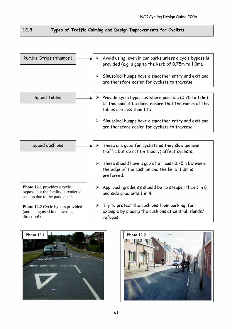
NCC Cycling Design Guide 2006
12.3 Types of Traffic Calming and Design Improvements for Cyclists
Avoid using, even in car parks unless a cycle bypass is provided (e.g. a gap to the kerb of 0.75m to 1.0m).
Sinusoidal humps have a smoother entry and exit and
are therefore easier for cyclists to traverse.
Rumble Strips (‘thumps’)
Provide cycle bypasses where possible (0.75 to 1.0m). If this cannot be done, ensure that the ramps of the tables are less than 1:15.
Sinusoidal humps have a smoother entry and exit and
are therefore easier for cyclists to traverse.
Speed Tables
These are good for cyclists as they slow general traffic but do not (in theory) affect cyclists.
These should have a gap of at least 0.75m between
the edge of the cushion and the kerb, 1.0m is preferred.
Approach gradients should be no steeper than 1 in 8
and side gradients 1 in 4.
Try to protect the cushions from parking, for example by placing the cushions at central islands/ refuges
Speed Cushions
Photo 12.1 provides a cycle bypass, but the facility is rendered useless due to the parked car. Photo 12.2 Cycle bypass provided (and being used in the wrong direction!)
Photo 12.1 Photo 12.2
61
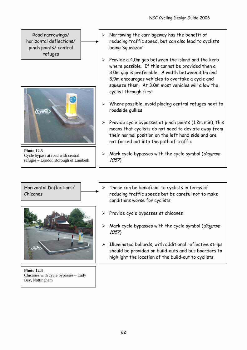
NCC Cycling Design Guide 2006
Narrowing the carriageway has the benefit of reducing traffic speed, but can also lead to cyclists being ‘squeezed’
Provide a 4.0m gap between the island and the kerb
where possible. If this cannot be provided then a 3.0m gap is preferable. A width between 3.1m and 3.9m encourages vehicles to overtake a cycle and squeeze them. At 3.0m most vehicles will allow the cyclist through first
Where possible, avoid placing central refuges next to
roadside gullies
Provide cycle bypasses at pinch points (1.2m min), this means that cyclists do not need to deviate away from their normal position on the left hand side and are not forced out into the path of traffic
Mark cycle bypasses with the cycle symbol (diagram
1057)
Road narrowings/ horizontal deflections/ pinch points/ central
refuges
Photo 12.3 Cycle bypass at road with central refuges – London Borough of Lambeth
These can be beneficial to cyclists in terms of reducing traffic speeds but be careful not to make conditions worse for cyclists
Provide cycle bypasses at chicanes
Mark cycle bypasses with the cycle symbol (diagram
1057)
Illuminated bollards, with additional reflective strips should be provided on build-outs and bus boarders to highlight the location of the build-out to cyclists
Horizontal Deflections/ Chicanes
Photo 12.4 Chicanes with cycle bypasses – Lady Bay, Nottingham
62
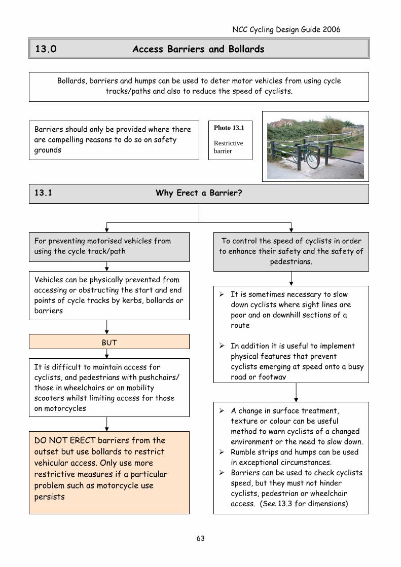
NCC Cycling Design Guide 2006
13.0 Access Barriers and Bollards
Bollards, barriers and humps can be used to deter motor vehicles from using cycle tracks/paths and also to reduce the speed of cyclists.
Photo 13.1 Restrictive barrier
Barriers should only be provided where there are compelling reasons to do so on safety grounds
13.1 Why Erect a Barrier?
For preventing motorised vehicles from using the cycle track/path
To control the speed of cyclists in order to enhance their safety and the safety of
pedestrians.
Vehicles can be physically prevented from accessing or obstructing the start and end points of cycle tracks by kerbs, bollards or barriers
It is sometimes necessary to slow down cyclists where sight lines are poor and on downhill sections of a route
In addition it is useful to implement
physical features that prevent cyclists emerging at speed onto a busy road or footway
BUT
It is difficult to maintain access for cyclists, and pedestrians with pushchairs/ those in wheelchairs or on mobility scooters whilst limiting access for those on motorcycles A change in surface treatment,
texture or colour can be useful method to warn cyclists of a changed environment or the need to slow down.
Rumble strips and humps can be used in exceptional circumstances.
Barriers can be used to check cyclists speed, but they must not hinder cyclists, pedestrian or wheelchair access. (See 13.3 for dimensions)
DO NOT ERECT barriers from the outset but use bollards to restrict vehicular access. Only use more restrictive measures if a particular problem such as motorcycle use persists
63
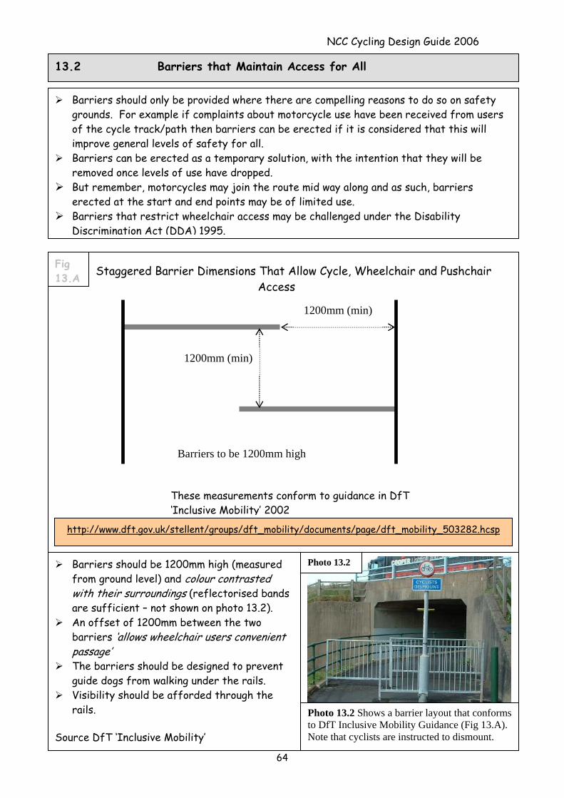
NCC Cycling Design Guide 2006
64
Barriers should be 1200mm high (measured from ground level) and colour contrasted with their surroundings (reflectorised bands are sufficient – not shown on photo 13.2).
An offset of 1200mm between the two barriers ‘allows wheelchair users convenient passage’
The barriers should be designed to prevent guide dogs from walking under the rails.
Visibility should be afforded through the rails.
Source DfT ‘Inclusive Mobility’
Barriers should only be provided where there are compelling reasons to do so on safety grounds. For example if complaints about motorcycle use have been received from users of the cycle track/path then barriers can be erected if it is considered that this will improve general levels of safety for all.
Barriers can be erected as a temporary solution, with the intention that they will be removed once levels of use have dropped.
But remember, motorcycles may join the route mid way along and as such, barriers erected at the start and end points may be of limited use.
Barriers that restrict wheelchair access may be challenged under the Disability Discrimination Act (DDA) 1995.
1200mm (min)
1200mm (min)
These measurements conform to guidance in DfT ‘Inclusive Mobility’ 2002
Barriers to be 1200mm high
Staggered Barrier Dimensions That Allow Cycle, Wheelchair and Pushchair Access
http://www.dft.gov.uk/stellent/groups/dft_mobility/documents/page/dft_mobility_503282.hcsp
Fig 13.A
Photo 13.2
Photo 13.2 Shows a barrier layout that conforms to DfT Inclusive Mobility Guidance (Fig 13.A). Note that cyclists are instructed to dismount.
13.2 Barriers that Maintain Access for All
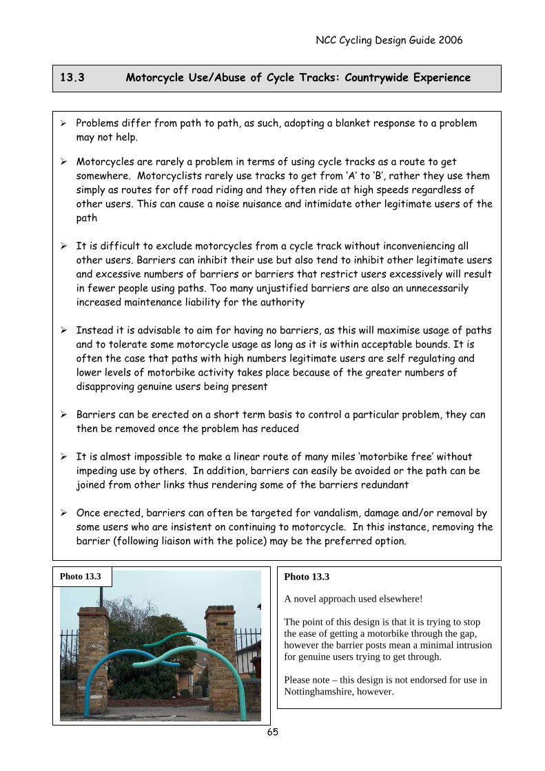
NCC Cycling Design Guide 2006
65
Problems differ from path to path, as such, adopting a blanket response to a problem may not help.
Motorcycles are rarely a problem in terms of using cycle tracks as a route to get
somewhere. Motorcyclists rarely use tracks to get from ‘A’ to ‘B’, rather they use them simply as routes for off road riding and they often ride at high speeds regardless of other users. This can cause a noise nuisance and intimidate other legitimate users of the path
It is difficult to exclude motorcycles from a cycle track without inconveniencing all
other users. Barriers can inhibit their use but also tend to inhibit other legitimate users and excessive numbers of barriers or barriers that restrict users excessively will result in fewer people using paths. Too many unjustified barriers are also an unnecessarily increased maintenance liability for the authority
Instead it is advisable to aim for having no barriers, as this will maximise usage of paths
and to tolerate some motorcycle usage as long as it is within acceptable bounds. It is often the case that paths with high numbers legitimate users are self regulating and lower levels of motorbike activity takes place because of the greater numbers of disapproving genuine users being present
Barriers can be erected on a short term basis to control a particular problem, they can
then be removed once the problem has reduced
It is almost impossible to make a linear route of many miles ‘motorbike free’ without impeding use by others. In addition, barriers can easily be avoided or the path can be joined from other links thus rendering some of the barriers redundant
Once erected, barriers can often be targeted for vandalism, damage and/or removal by
some users who are insistent on continuing to motorcycle. In this instance, removing the barrier (following liaison with the police) may be the preferred option.
13.3 Motorcycle Use/Abuse of Cycle Tracks: Countrywide Experience
Photo 13.3 A novel approach used elsewhere! The point of this design is that it is trying to stop the ease of getting a motorbike through the gap, however the barrier posts mean a minimal intrusion for genuine users trying to get through. Please note – this design is not endorsed for use in Nottinghamshire, however.
Photo 13.3
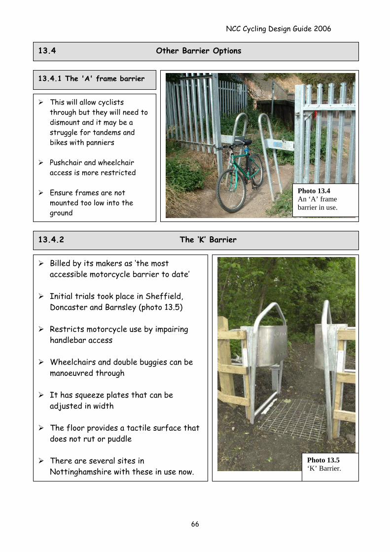
NCC Cycling Design Guide 2006
13.4 Other Barrier Options
13.4.1 The 'A' frame barrier
Photo 13.4 An ‘A’ frame barrier in use.
This will allow cyclists through but they will need to dismount and it may be a struggle for tandems and bikes with panniers
Pushchair and wheelchair
access is more restricted
Ensure frames are not mounted too low into the ground
13.4.2 The ‘K’ Barrier
Billed by its makers as ‘the most accessible motorcycle barrier to date’
Initial trials took place in Sheffield,
Doncaster and Barnsley (photo 13.5)
Restricts motorcycle use by impairing handlebar access
Wheelchairs and double buggies can be
manoeuvred through
It has squeeze plates that can be adjusted in width
The floor provides a tactile surface that
does not rut or puddle
There are several sites in Nottinghamshire with these in use now.
Photo 13.5 ‘K’ Barrier.
66
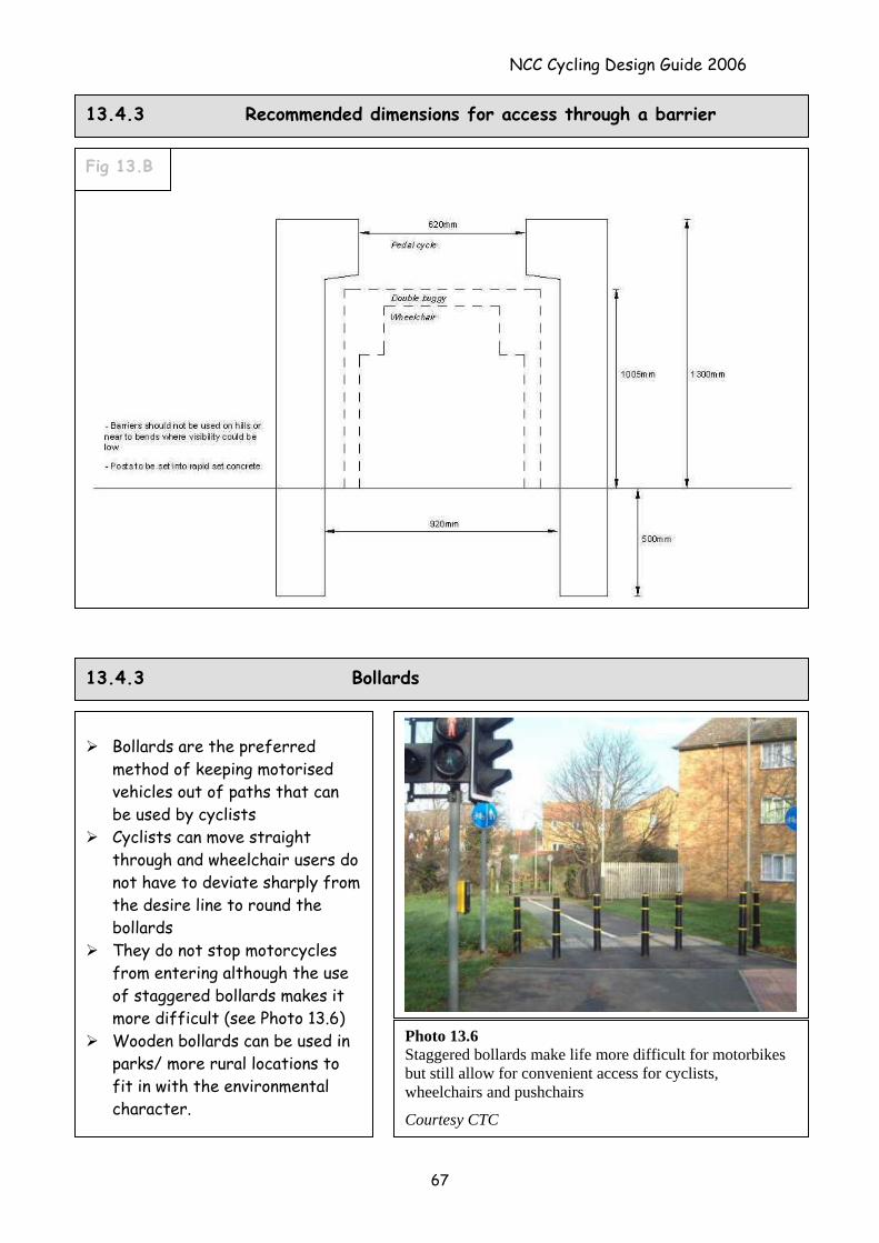
NCC Cycling Design Guide 2006
13.4.3 Recommended dimensions for access through a barrier
Fig 13.B
13.4.3 Bollards
Bollards are the preferred method of keeping motorised vehicles out of paths that can be used by cyclists
Cyclists can move straight through and wheelchair users do not have to deviate sharply from the desire line to round the bollards
They do not stop motorcycles from entering although the use of staggered bollards makes it more difficult (see Photo 13.6)
Wooden bollards can be used in parks/ more rural locations to fit in with the environmental character.
Photo 13.6 Staggered bollards make life more difficult for motorbikes but still allow for convenient access for cyclists, wheelchairs and pushchairs
Courtesy CTC
67
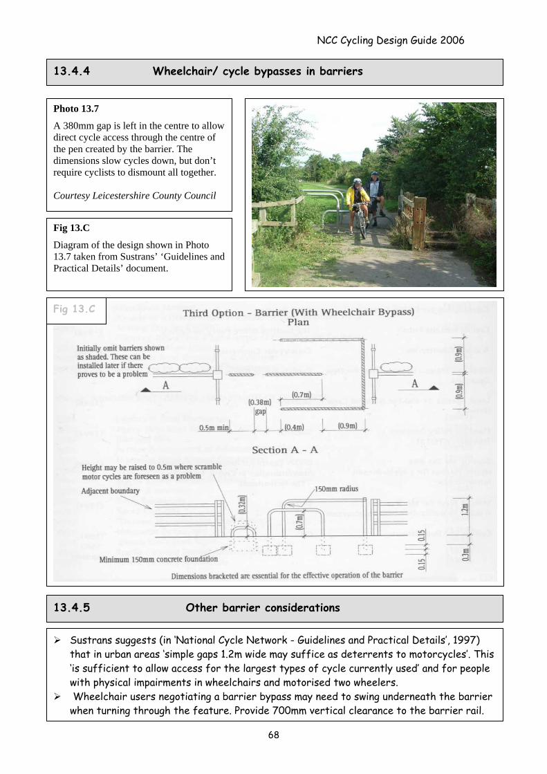
NCC Cycling Design Guide 2006
Sustrans suggests (in ‘National Cycle Network - Guidelines and Practical Details’, 1997) that in urban areas ‘simple gaps 1.2m wide may suffice as deterrents to motorcycles’. This ‘is sufficient to allow access for the largest types of cycle currently used’ and for people with physical impairments in wheelchairs and motorised two wheelers.
Wheelchair users negotiating a barrier bypass may need to swing underneath the barrier when turning through the feature. Provide 700mm vertical clearance to the barrier rail.
Photo 13.7
A 380mm gap is left in the centre to allow direct cycle access through the centre of the pen created by the barrier. The dimensions slow cycles down, but don’t require cyclists to dismount all together. Courtesy Leicestershire County Council
13.4.4 Wheelchair/ cycle bypasses in barriers
13.4.5 Other barrier considerations
Diagram of the design shown in Photo 13.7 taken from Sustrans’ ‘Guidelines and Practical Details’ document.
Fig 13.C
Fig 13.C
68
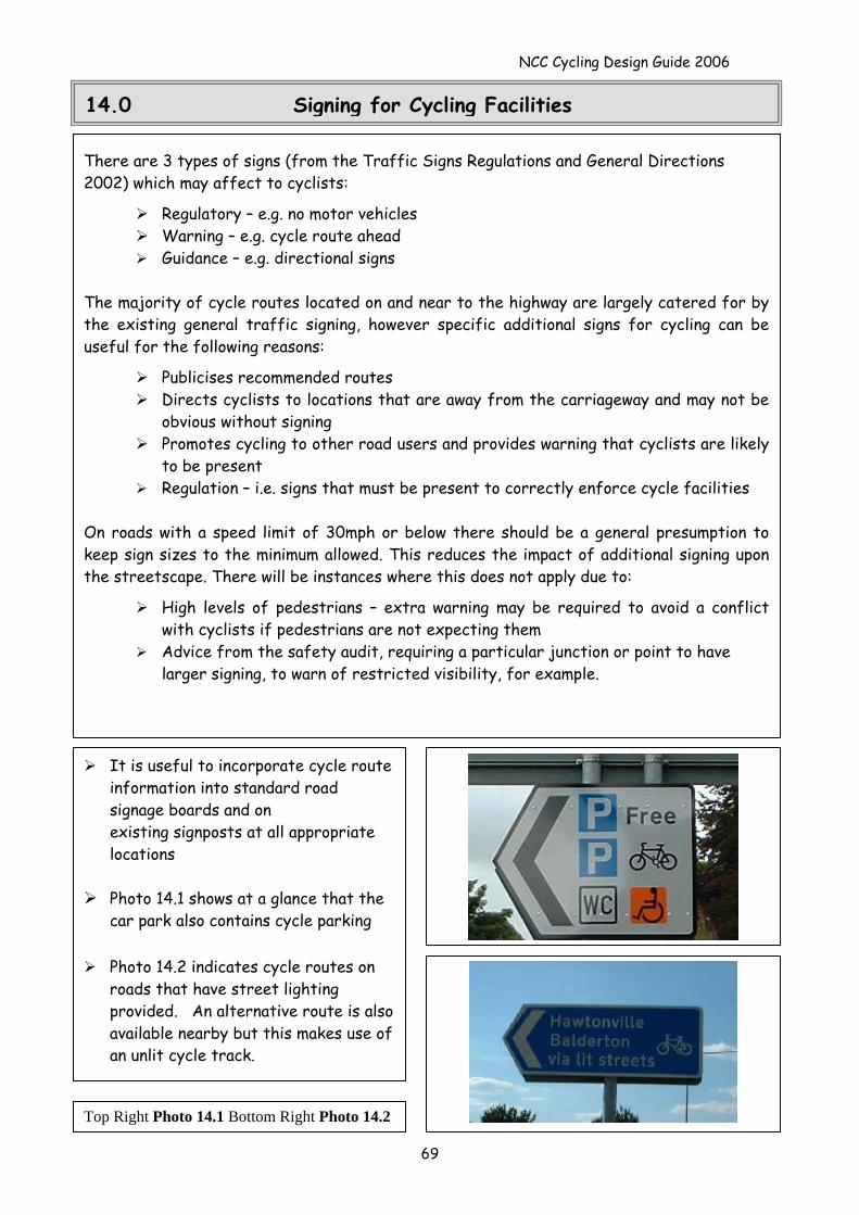
NCC Cycling Design Guide 2006
14.0 Signing for Cycling Facilities
There are 3 types of signs (from the Traffic Signs Regulations and General Directions 2002) which may affect to cyclists:
Regulatory – e.g. no motor vehicles Warning – e.g. cycle route ahead Guidance – e.g. directional signs
The majority of cycle routes located on and near to the highway are largely catered for by the existing general traffic signing, however specific additional signs for cycling can be useful for the following reasons:
Publicises recommended routes Directs cyclists to locations that are away from the carriageway and may not be
obvious without signing Promotes cycling to other road users and provides warning that cyclists are likely
to be present Regulation – i.e. signs that must be present to correctly enforce cycle facilities
On roads with a speed limit of 30mph or below there should be a general presumption to keep sign sizes to the minimum allowed. This reduces the impact of additional signing upon the streetscape. There will be instances where this does not apply due to:
High levels of pedestrians – extra warning may be required to avoid a conflict with cyclists if pedestrians are not expecting them
Advice from the safety audit, requiring a particular junction or point to have larger signing, to warn of restricted visibility, for example.
It is useful to incorporate cycle route information into standard road signage boards and on existing signposts at all appropriate locations
Photo 14.1 shows at a glance that the
car park also contains cycle parking
Photo 14.2 indicates cycle routes on roads that have street lighting provided. An alternative route is also available nearby but this makes use of an unlit cycle track.
Top Right Photo 14.1 Bottom Right Photo 14.2
69
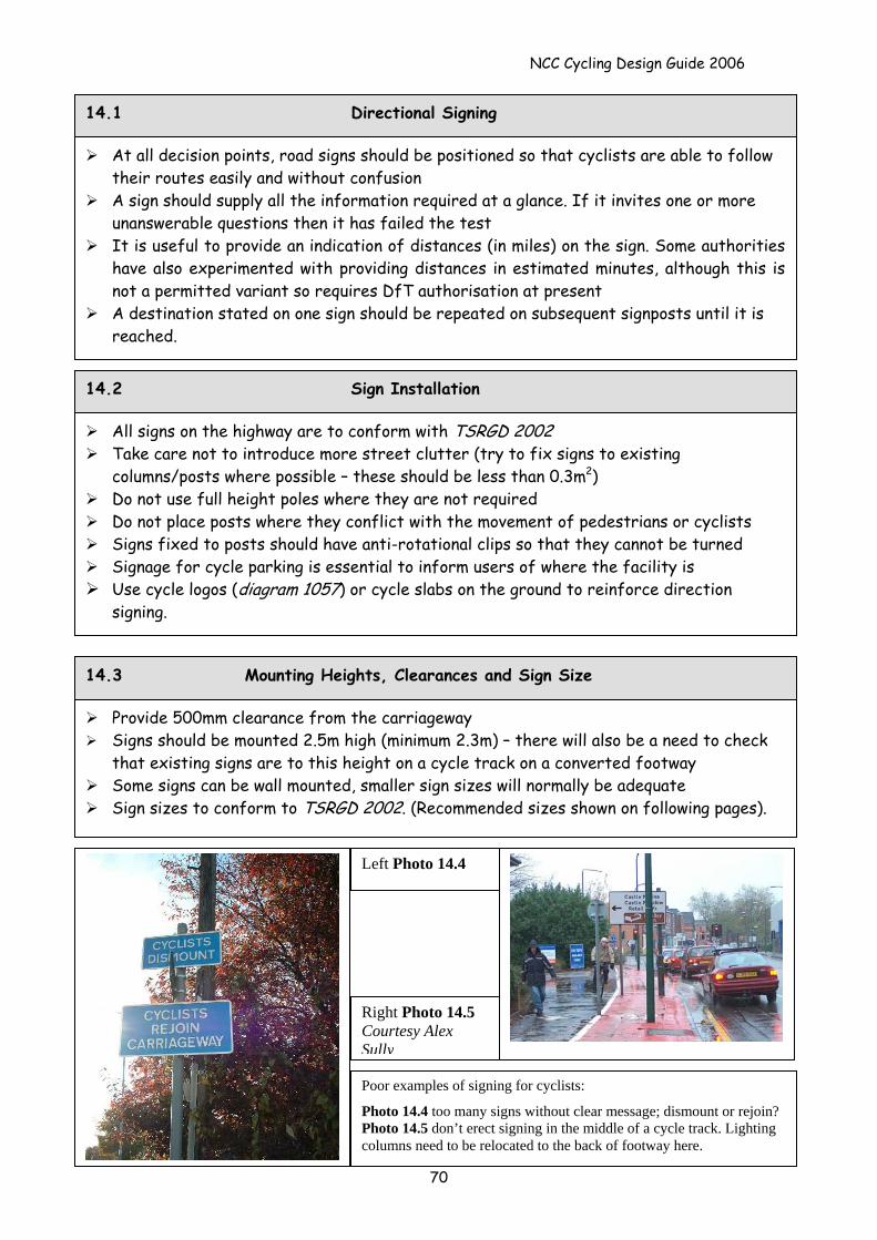
NCC Cycling Design Guide 2006
14.1 Directional Signing
At all decision points, road signs should be positioned so that cyclists are able to follow their routes easily and without confusion
A sign should supply all the information required at a glance. If it invites one or more unanswerable questions then it has failed the test
It is useful to provide an indication of distances (in miles) on the sign. Some authorities have also experimented with providing distances in estimated minutes, although this is not a permitted variant so requires DfT authorisation at present
A destination stated on one sign should be repeated on subsequent signposts until it is reached.
All signs on the highway are to conform with TSRGD 2002 Take care not to introduce more street clutter (try to fix signs to existing
columns/posts where possible – these should be less than 0.3m2) Do not use full height poles where they are not required Do not place posts where they conflict with the movement of pedestrians or cyclists Signs fixed to posts should have anti-rotational clips so that they cannot be turned Signage for cycle parking is essential to inform users of where the facility is Use cycle logos (diagram 1057) or cycle slabs on the ground to reinforce direction
signing.
14.2 Sign Installation
Provide 500mm clearance from the carriageway Signs should be mounted 2.5m high (minimum 2.3m) – there will also be a need to check
that existing signs are to this height on a cycle track on a converted footway Some signs can be wall mounted, smaller sign sizes will normally be adequate Sign sizes to conform to TSRGD 2002. (Recommended sizes shown on following pages).
14.3 Mounting Heights, Clearances and Sign Size
70
Poor examples of signing for cyclists:
Photo 14.4 too many signs without clear message; dismount or rejoin? Photo 14.5 don’t erect signing in the middle of a cycle track. Lighting columns need to be relocated to the back of footway here.
Right Photo 14.5 Courtesy Alex Sully
Left Photo 14.4
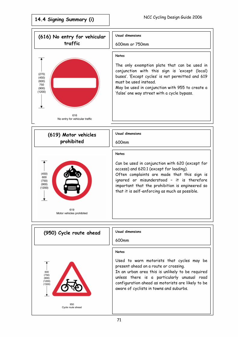
14.4 Signing Summary (i) NCC Cycling Design Guide 2006
71
Notes The only exemption plate that can be used in conjunction with this sign is ‘except (local) buses’. ‘Except cycles’ is not permitted and 619 must be used instead. May be used in conjunction with 955 to create a ‘false’ one way street with a cycle bypass.
Usual dimensions 600mm or 750mm
(616) No entry for vehicular traffic
Notes Can be used in conjunction with 620 (except for access) and 620.1 (except for loading). Often complaints are made that this sign is ignored or misunderstood – it is therefore important that the prohibition is engineered so that it is self-enforcing as much as possible.
Usual dimensions 600mm
(619) Motor vehicles prohibited
Notes Used to warn motorists that cycles may be present ahead on a route or crossing. In an urban area this is unlikely to be required unless there is a particularly unusual road configuration ahead as motorists are likely to be aware of cyclists in towns and suburbs.
Usual dimensions 600mm
(950) Cycle route ahead
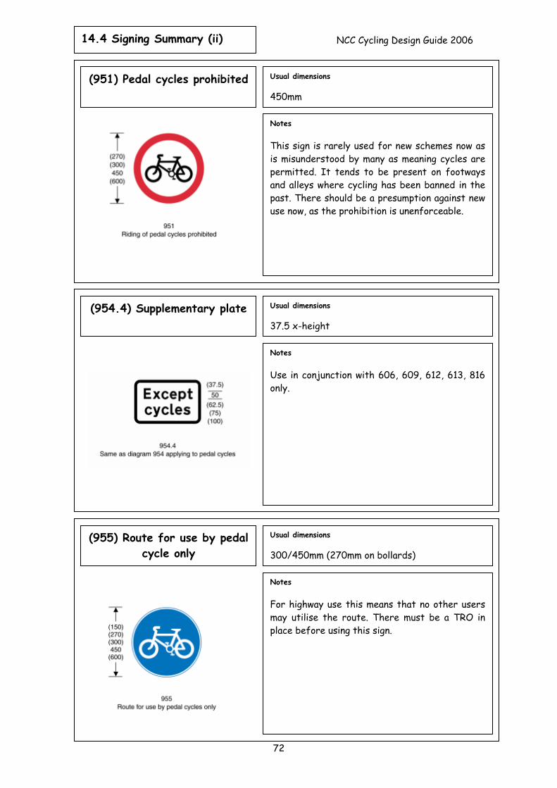
14.4 Signing Summary (ii) NCC Cycling Design Guide 2006
72
Notes This sign is rarely used for new schemes now as is misunderstood by many as meaning cycles are permitted. It tends to be present on footways and alleys where cycling has been banned in the past. There should be a presumption against new use now, as the prohibition is unenforceable.
Usual dimensions 450mm
(951) Pedal cycles prohibited
Notes Use in conjunction with 606, 609, 612, 613, 816 only.
Usual dimensions 37.5 x-height
(954.4) Supplementary plate
Notes For highway use this means that no other users may utilise the route. There must be a TRO in place before using this sign.
Usual dimensions 300/450mm (270mm on bollards)
(955) Route for use by pedal cycle only
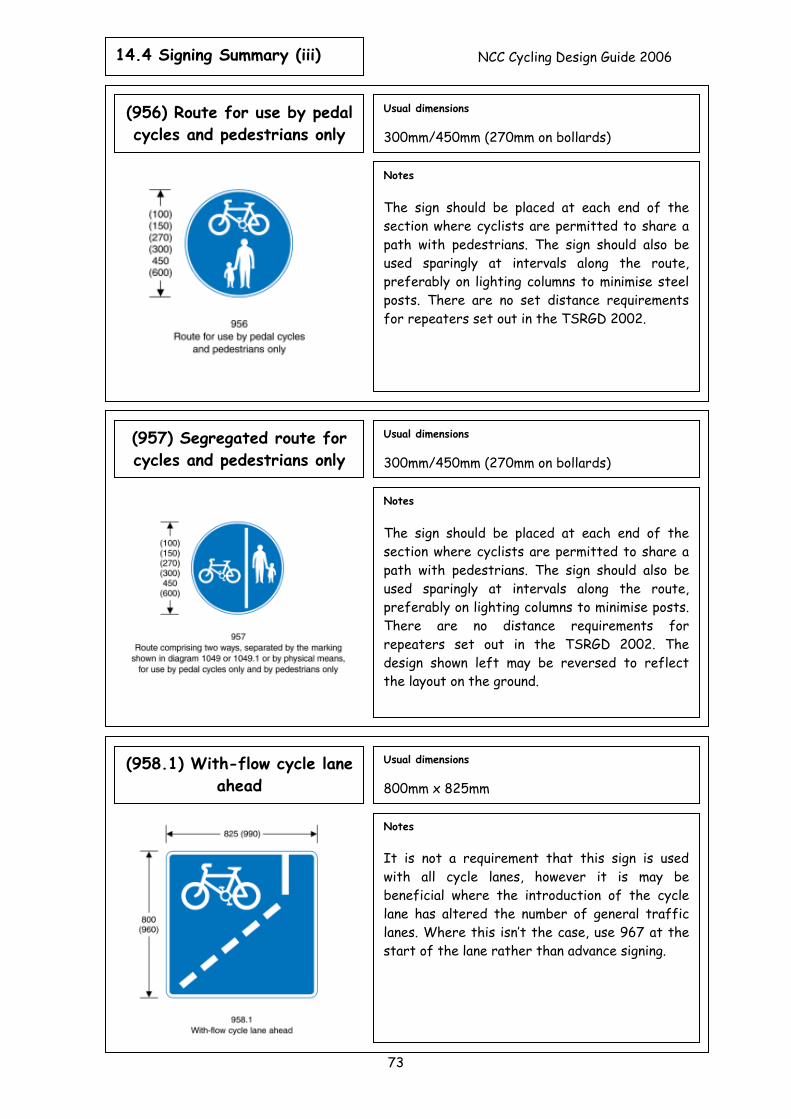
14.4 Signing Summary (iii) NCC Cycling Design Guide 2006
73
Notes The sign should be placed at each end of the section where cyclists are permitted to share a path with pedestrians. The sign should also be used sparingly at intervals along the route, preferably on lighting columns to minimise posts. There are no distance requirements for repeaters set out in the TSRGD 2002. The design shown left may be reversed to reflect the layout on the ground.
Usual dimensions 300mm/450mm (270mm on bollards)
(957) Segregated route for cycles and pedestrians only
Notes The sign should be placed at each end of the section where cyclists are permitted to share a path with pedestrians. The sign should also be used sparingly at intervals along the route, preferably on lighting columns to minimise steel posts. There are no set distance requirements for repeaters set out in the TSRGD 2002.
Usual dimensions 300mm/450mm (270mm on bollards)
(956) Route for use by pedal cycles and pedestrians only
Notes It is not a requirement that this sign is used with all cycle lanes, however it is may be beneficial where the introduction of the cycle lane has altered the number of general traffic lanes. Where this isn’t the case, use 967 at the start of the lane rather than advance signing.
Usual dimensions 800mm x 825mm
(958.1) With-flow cycle lane ahead
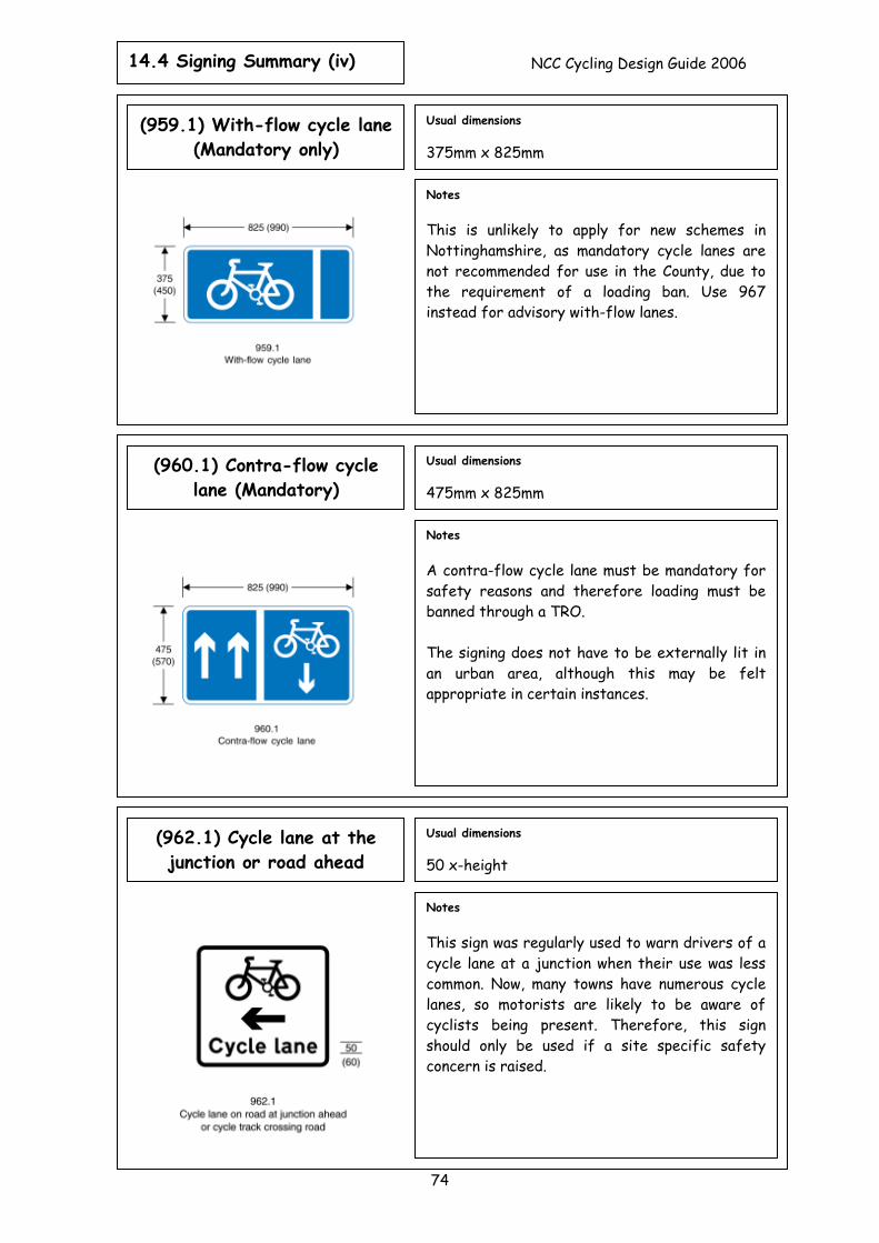
14.4 Signing Summary (iv) NCC Cycling Design Guide 2006
74
Notes This sign was regularly used to warn drivers of a cycle lane at a junction when their use was less common. Now, many towns have numerous cycle lanes, so motorists are likely to be aware of cyclists being present. Therefore, this sign should only be used if a site specific safety concern is raised.
Usual dimensions 50 x-height
(962.1) Cycle lane at the junction or road ahead
Notes A contra-flow cycle lane must be mandatory for safety reasons and therefore loading must be banned through a TRO. The signing does not have to be externally lit in an urban area, although this may be felt appropriate in certain instances.
Usual dimensions 475mm x 825mm
(960.1) Contra-flow cycle lane (Mandatory)
Notes This is unlikely to apply for new schemes in Nottinghamshire, as mandatory cycle lanes are not recommended for use in the County, due to the requirement of a loading ban. Use 967 instead for advisory with-flow lanes.
Usual dimensions 375mm x 825mm
(959.1) With-flow cycle lane (Mandatory only)
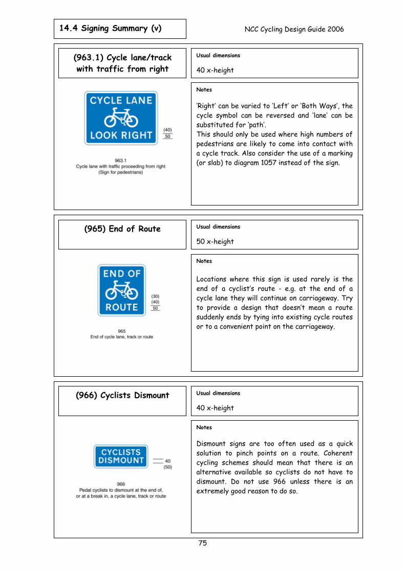
14.4 Signing Summary (v) NCC Cycling Design Guide 2006
75
Notes ‘Right’ can be varied to ‘Left’ or ‘Both Ways’, the cycle symbol can be reversed and ‘lane’ can be substituted for ‘path’. This should only be used where high numbers of pedestrians are likely to come into contact with a cycle track. Also consider the use of a marking (or slab) to diagram 1057 instead of the sign.
Usual dimensions 40 x-height
(963.1) Cycle lane/track with traffic from right
Notes Locations where this sign is used rarely is the end of a cyclist’s route - e.g. at the end of a cycle lane they will continue on carriageway. Try to provide a design that doesn’t mean a route suddenly ends by tying into existing cycle routes or to a convenient point on the carriageway.
Usual dimensions 50 x-height
(965) End of Route
Notes Dismount signs are too often used as a quick solution to pinch points on a route. Coherent cycling schemes should mean that there is an alternative available so cyclists do not have to dismount. Do not use 966 unless there is an extremely good reason to do so.
Usual dimensions 40 x-height
(966) Cyclists Dismount
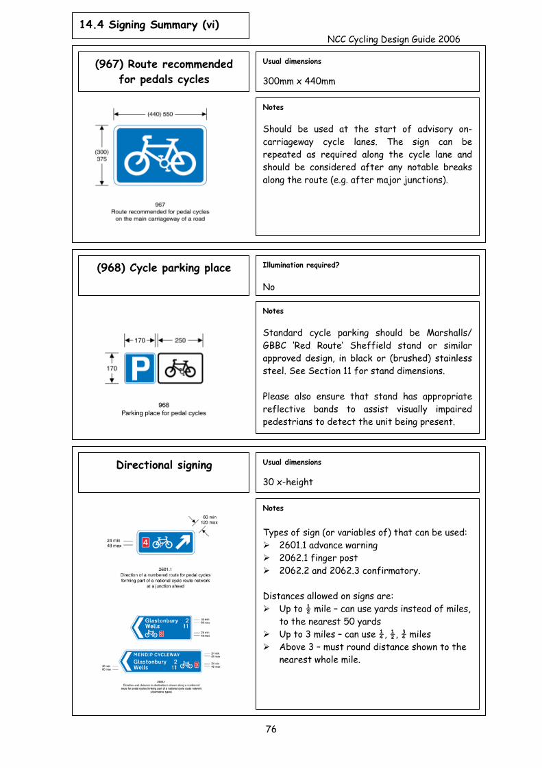
14.4 Signing Summary (vi) NCC Cycling Design Guide 2006
76
Notes Should be used at the start of advisory on-carriageway cycle lanes. The sign can be repeated as required along the cycle lane and should be considered after any notable breaks along the route (e.g. after major junctions).
Usual dimensions 300mm x 440mm
(967) Route recommended for pedals cycles
Notes Standard cycle parking should be Marshalls/ GBBC ‘Red Route’ Sheffield stand or similar approved design, in black or (brushed) stainless steel. See Section 11 for stand dimensions. Please also ensure that stand has appropriate reflective bands to assist visually impaired pedestrians to detect the unit being present.
Illumination required? No
(968) Cycle parking place
Usual dimensions 30 x-height
Notes Types of sign (or variables of) that can be used:
2601.1 advance warning 2062.1 finger post 2062.2 and 2062.3 confirmatory.
Distances allowed on signs are:
Up to ½ mile – can use yards instead of miles, to the nearest 50 yards
Up to 3 miles – can use ¼, ½, ¾ miles Above 3 – must round distance shown to the
nearest whole mile.
Directional signing
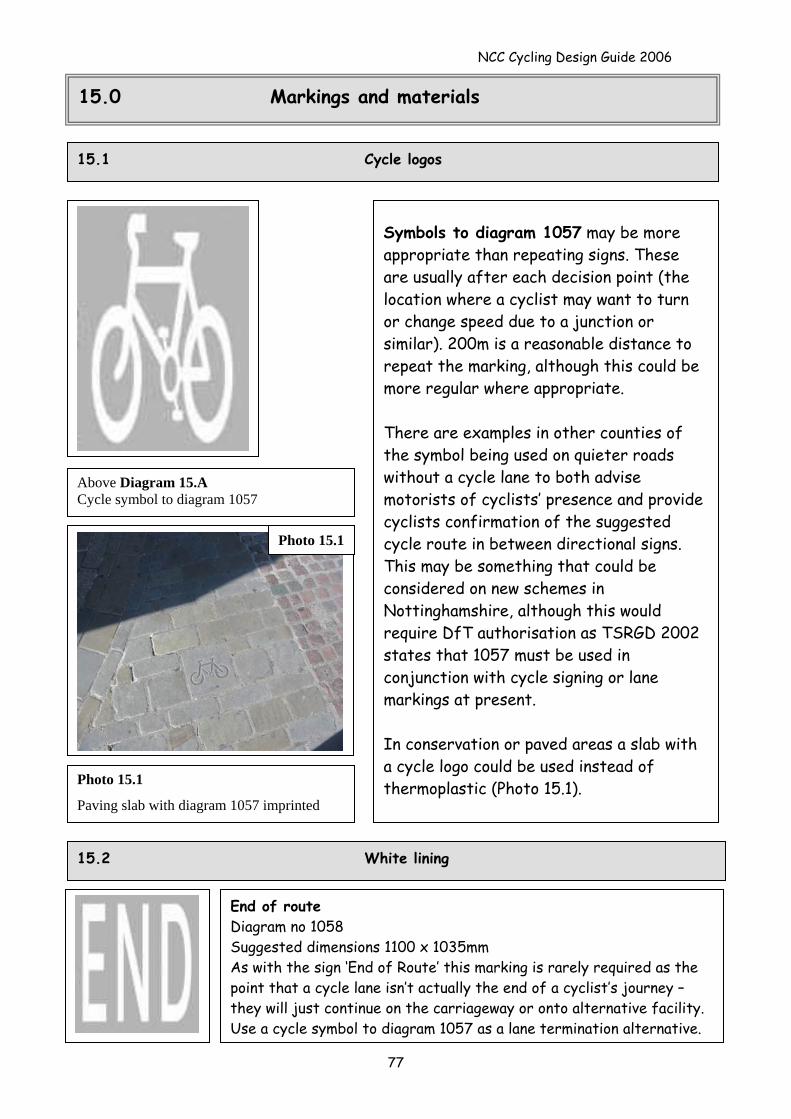
NCC Cycling Design Guide 2006
15.0 Markings and materials
15.1 Cycle logos
Symbols to diagram 1057 may be more appropriate than repeating signs. These are usually after each decision point (the location where a cyclist may want to turn or change speed due to a junction or similar). 200m is a reasonable distance to repeat the marking, although this could be more regular where appropriate. There are examples in other counties of the symbol being used on quieter roads without a cycle lane to both advise motorists of cyclists’ presence and provide cyclists confirmation of the suggested cycle route in between directional signs. This may be something that could be considered on new schemes in Nottinghamshire, although this would require DfT authorisation as TSRGD 2002 states that 1057 must be used in conjunction with cycle signing or lane markings at present. In conservation or paved areas a slab with a cycle logo could be used instead of thermoplastic (Photo 15.1).
Above Diagram 15.A Cycle symbol to diagram 1057
Photo 15.1
Photo 15.1
Paving slab with diagram 1057 imprinted
15.2 White lining
End of route Diagram no 1058 Suggested dimensions 1100 x 1035mm As with the sign ‘End of Route’ this marking is rarely required as the point that a cycle lane isn’t actually the end of a cyclist’s journey – they will just continue on the carriageway or onto alternative facility. Use a cycle symbol to diagram 1057 as a lane termination alternative.
77
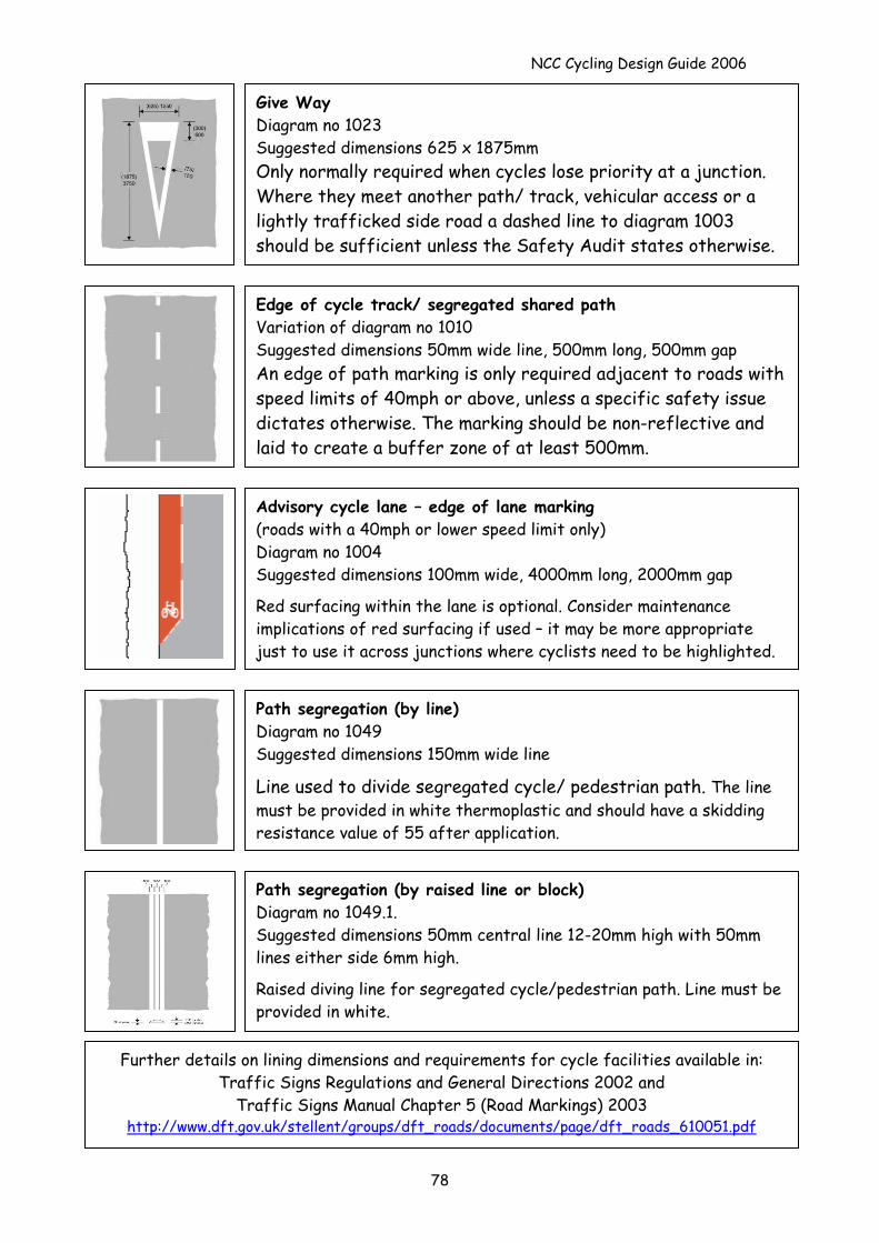
NCC Cycling Design Guide 2006
Give Way Diagram no 1023 Suggested dimensions 625 x 1875mm Only normally required when cycles lose priority at a junction. Where they meet another path/ track, vehicular access or a lightly trafficked side road a dashed line to diagram 1003 should be sufficient unless the Safety Audit states otherwise.
Edge of cycle track/ segregated shared path Variation of diagram no 1010 Suggested dimensions 50mm wide line, 500mm long, 500mm gap An edge of path marking is only required adjacent to roads with speed limits of 40mph or above, unless a specific safety issue dictates otherwise. The marking should be non-reflective and laid to create a buffer zone of at least 500mm.
Path segregation (by line) Diagram no 1049 Suggested dimensions 150mm wide line
Line used to divide segregated cycle/ pedestrian path. The line must be provided in white thermoplastic and should have a skidding resistance value of 55 after application.
Path segregation (by raised line or block) Diagram no 1049.1. Suggested dimensions 50mm central line 12-20mm high with 50mm lines either side 6mm high.
Raised diving line for segregated cycle/pedestrian path. Line must be provided in white.
Further details on lining dimensions and requirements for cycle facilities available in: Traffic Signs Regulations and General Directions 2002 and
Traffic Signs Manual Chapter 5 (Road Markings) 2003 http://www.dft.gov.uk/stellent/groups/dft_roads/documents/page/dft_roads_610051.pdf
Advisory cycle lane – edge of lane marking (roads with a 40mph or lower speed limit only) Diagram no 1004 Suggested dimensions 100mm wide, 4000mm long, 2000mm gap
Red surfacing within the lane is optional. Consider maintenance implications of red surfacing if used – it may be more appropriate just to use it across junctions where cyclists need to be highlighted.
78
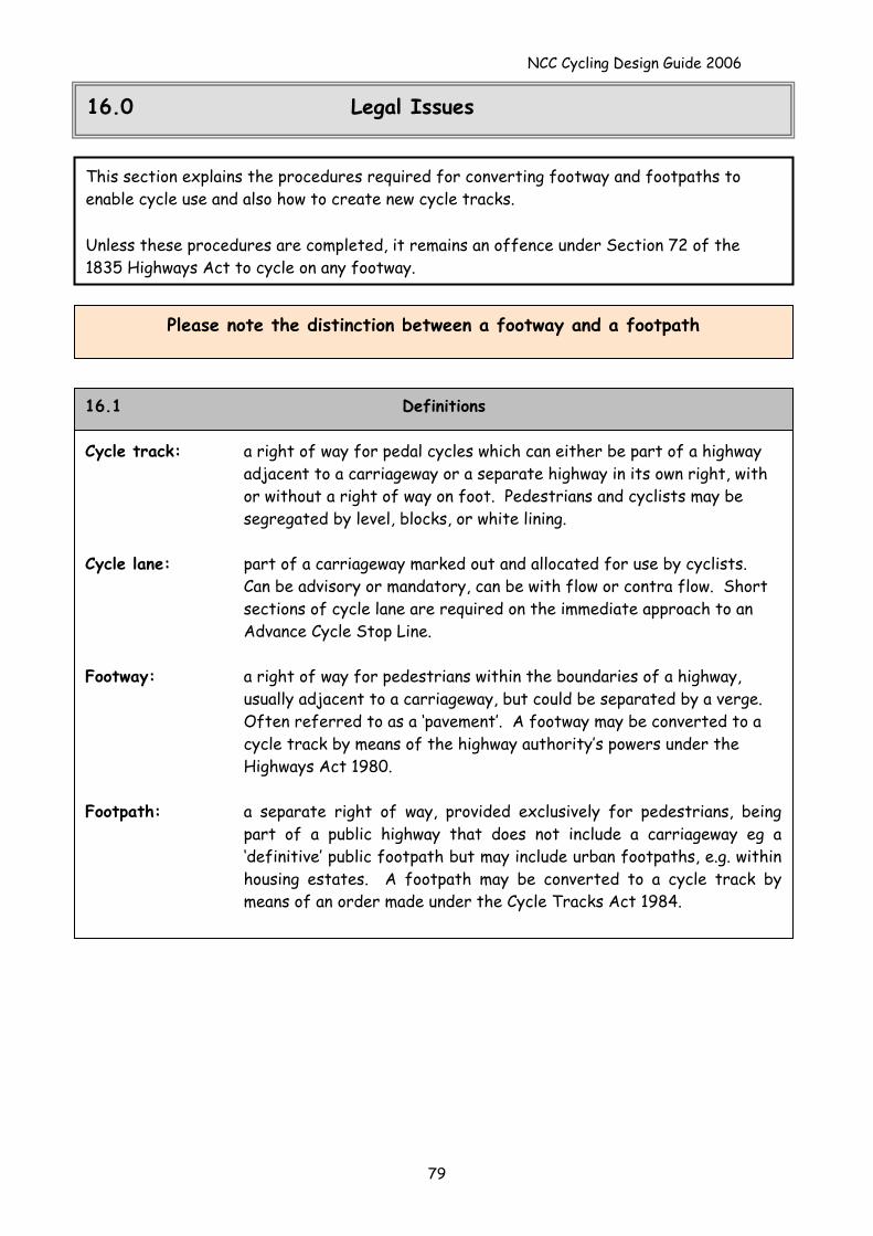
NCC Cycling Design Guide 2006
16.0 Legal Issues
This section explains the procedures required for converting footway and footpaths to enable cycle use and also how to create new cycle tracks. Unless these procedures are completed, it remains an offence under Section 72 of the 1835 Highways Act to cycle on any footway.
Please note the distinction between a footway and a footpath
: Cycle track: a right of way for pedal cycles which can either be part of a highway
adjacent to a carriageway or a separate highway in its own right, with or without a right of way on foot. Pedestrians and cyclists may be segregated by level, blocks, or white lining.
Cycle lane: part of a carriageway marked out and allocated for use by cyclists.
Can be advisory or mandatory, can be with flow or contra flow. Short sections of cycle lane are required on the immediate approach to an Advance Cycle Stop Line.
Footway: a right of way for pedestrians within the boundaries of a highway,
usually adjacent to a carriageway, but could be separated by a verge. Often referred to as a ‘pavement’. A footway may be converted to a cycle track by means of the highway authority’s powers under the Highways Act 1980.
Footpath: a separate right of way, provided exclusively for pedestrians, being
part of a public highway that does not include a carriageway eg a ‘definitive’ public footpath but may include urban footpaths, e.g. within housing estates. A footpath may be converted to a cycle track by means of an order made under the Cycle Tracks Act 1984.
16.1 Definitions
79
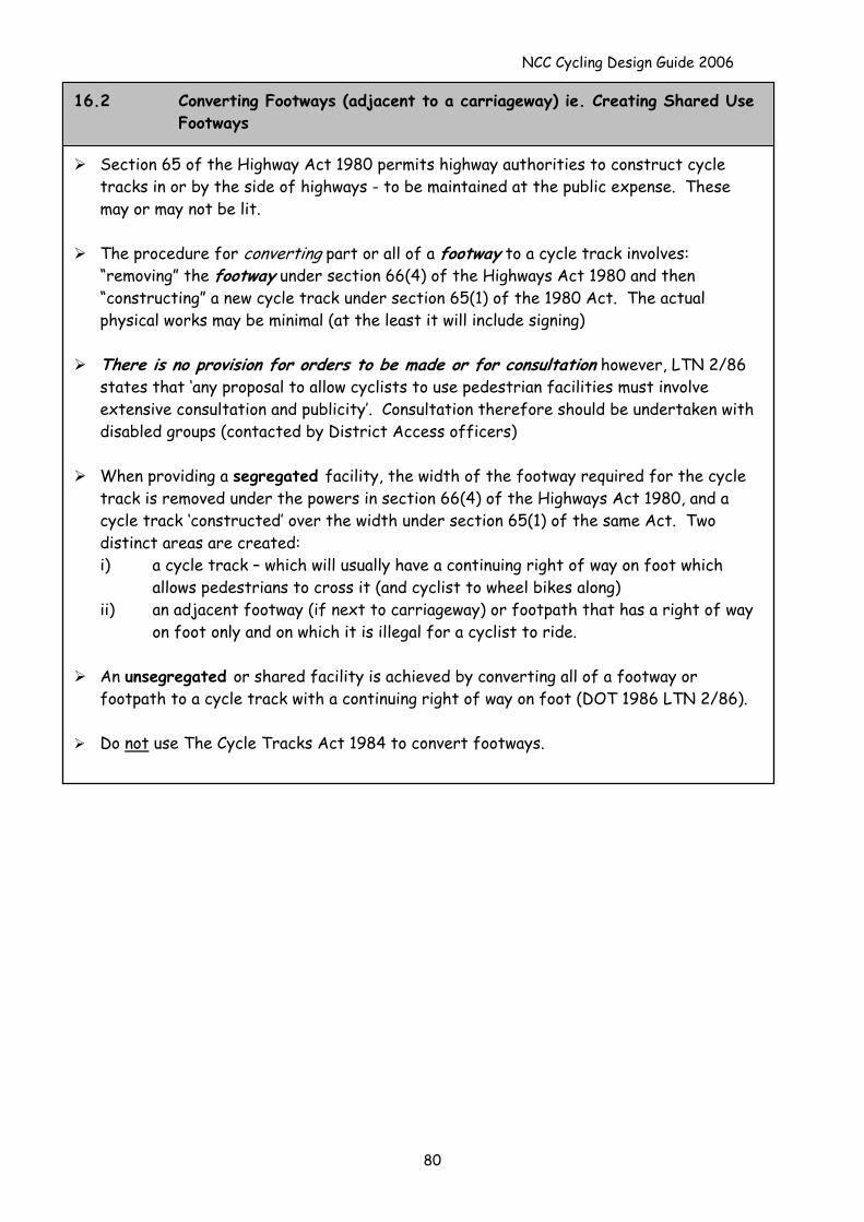
NCC Cycling Design Guide 2006
Section 65 of the Highway Act 1980 permits highway authorities to construct cycle
tracks in or by the side of highways - to be maintained at the public expense. These may or may not be lit.
The procedure for converting part or all of a footway to a cycle track involves:
“removing” the footway under section 66(4) of the Highways Act 1980 and then “constructing” a new cycle track under section 65(1) of the 1980 Act. The actual physical works may be minimal (at the least it will include signing)
There is no provision for orders to be made or for consultation however, LTN 2/86
states that ‘any proposal to allow cyclists to use pedestrian facilities must involve extensive consultation and publicity’. Consultation therefore should be undertaken with disabled groups (contacted by District Access officers)
When providing a segregated facility, the width of the footway required for the cycle
track is removed under the powers in section 66(4) of the Highways Act 1980, and a cycle track ‘constructed’ over the width under section 65(1) of the same Act. Two distinct areas are created: i) a cycle track – which will usually have a continuing right of way on foot which
allows pedestrians to cross it (and cyclist to wheel bikes along) ii) an adjacent footway (if next to carriageway) or footpath that has a right of way
on foot only and on which it is illegal for a cyclist to ride.
An unsegregated or shared facility is achieved by converting all of a footway or footpath to a cycle track with a continuing right of way on foot (DOT 1986 LTN 2/86).
Do not use The Cycle Tracks Act 1984 to convert footways.
16.2 Converting Footways (adjacent to a carriageway) ie. Creating Shared Use Footways
80
NCC Cycling Design Guide 2006
81
16.3 Converting Footpaths
These orders are made under section 3 of the Cycle Tracks Act 1984 and the procedures in Cycle Tracks Regulation 1984 (SI 1984/1431).
Under decision J1.34, the Planning Committee has delegated powers to the Highway
Services Group Manager to convert footpaths into cycle tracks. Any proposals to convert should therefore be directed to the Highway Services Group Manager in the first instance prior to discussions with legal.
This allows for the conversion of all or part of the footpath to a cycle track with a right
of way on foot, where the County Council is the highway authority (there is no authority to create a cycle track on a private footpath). On conversion, the footpath becomes a highway, that is maintainable at public expense (section 36 of the Highways Act 1980) even if the footpath had not previously had that status.
If Agricultural Land is involved, written consent of all those having a legal interest in the
land needs to be obtained.
Procedure for making an order. On making an order, the Highway authority shall consult with the following: i) one or more organisation representing people who use the footpath to which the
order relates or are likely to be affected by any provisions of the order, unless it appears to the authority that there is no such organisation which can appropriately be considered.
ii) Any other local authority, parish council or community council within whose area the said footpath is situated.
iii) Those statutory undertakers whose operational land is crossed by the said footpath iv) The chief officer of police of any police area in which the said footpath is siutated. • Publish and display notices in newspapers and on site. • A model order is available on request (this is from DoT 1986)
A local authority can make and confirm an order under section 3 (1984) if there are no unwithdrawn objections. If unwithdrawn objections remain, the order has to be confirmed by the Secretary of State, and usually a public local inquiry is held. In the event of a public inquiry please contact the Cycling Officer for information.
If the order is made, then the footpath must be deleted from the definitive map of
footpaths. If only part of the footpath is converted then the will be two distinct but adjacent ways, a cycle track and a footpath. As the footpath remains in existence, it can remain on the definitive map.
An alternative method is to create a new cycle track adjacent to the existing footpath
under the Highways Act 1980. This will result in a footpath running adjacent to a cycle track (which is highway). This is dependent on land ownership (landowners can dedicate the land to highway). Land owners can also give permissive access to the land.
NCC Cycling Design Guide 2006
Cyclists are permitted to use bridleways, as are pedestrians and horses (1968 Countryside
Act), although the surface material may not necessarily be best suited to cycling. Bridleways cannot be converted to cycle tracks (and indeed there is no need to do so).
16.4 Bridleways
Cyclists are permitted to cycle on some canal towpaths (note that permits are required for some).
16.5 Towpaths
1. Identify the land owners over which the track is proposed, by way of enquiries in the
locality and the posting of site notices. Undertake a Commons Registration search. 2. Complete the relevant notices and certificates required under section 27 of the Town
and Country Planning Act 1971 depending on whether ownership is known 3. Obtain deemed planning permission under Regulation 4 of the Town and Country Planning
General Regulations 1976. Consult with the District Council involved. 4. Seek planning permission to construct a cycle track from relevant committee 5. Construct a cycle track under section 24 of the Highways Act 1980 6. A cycle track can be defined for use by cycles only.
16.6 Procedure for creating a new cycle track (non-highway)
82