Embed Size (px)
Citation preview
General rights Copyright and moral rights for the publications made accessible in the public portal are retained by the authors and/or other copyright owners and it is a condition of accessing publications that users recognise and abide by the legal requirements associated with these rights.
Users may download and print one copy of any publication from the public portal for the purpose of private study or research.
You may not further distribute the material or use it for any profit-making activity or commercial gain
You may freely distribute the URL identifying the publication in the public portal If you believe that this document breaches copyright please contact us providing details, and we will remove access to the work immediately and investigate your claim.
Downloaded from orbit.dtu.dk on: Aug 15, 2019
Cyclic distillation technology - A mini-review
Bîldea, Costin Sorin; Ptru, Ctlin; Jørgensen, Sten Bay; Abildskov, Jens; Kiss, Anton A.
Published in:Journal of Chemical Technology and Biotechnology
Link to article, DOI:10.1002/jctb.4887
Publication date:2016
Document VersionPeer reviewed version
Link back to DTU Orbit
Citation (APA):Bîldea, C. S., Ptru, C., Jørgensen, S. B., Abildskov, J., & Kiss, A. A. (2016). Cyclic distillation technology - Amini-review. Journal of Chemical Technology and Biotechnology, 91, 1215-1223.https://doi.org/10.1002/jctb.4887
Acc
epte
d A
rticl
eCyclic distillation technology – A mini-review
Costin Sorin Bîldea,1 Cătălin Pătruţ,1
Sten Bay Jørgensen,2 Jens Abildskov,2 Anton A. Kiss3,4 1 University “Politehnica” of Bucharest, Polizu 1-7, 011061 Bucharest, Romania.
2 CAPEC-PROCESS, Department of Chemical and Biochemical Engineering. Building 229,
Technical University of Denmark, 2800 Kgs. Lyngby, Denmark 3 AkzoNobel – Supply Chain, Research & Development, Process Technology SRG,
Zutphenseweg 10, 7418 AJ Deventer, The Netherlands. E-mail: [email protected] 4 Sustainable Process Technology Group, Faculty of Science and Technology, University of
Twente, PO Box 217, 7500 AE, Enschede, The Netherlands
Abstract
Process intensification in distillation systems has received much attention during the past
decades, with the aim of increasing both energy and separation efficiency. Various
techniques, such as internal heat-integrated distillation, membrane distillation, rotating packed
bed, dividing-wall columns and reactive distillation were studied and reported in literature.
All these techniques employ the conventional continuous counter-current contact of vapor and
liquid phases. Cyclic distillation technology is based on an alternative operating mode using
separate phase movement which leads to key practical advantages in both chemical and
biochemical processes. This article provides a mini-review of cyclic distillation technology.
The topics covered include the working principle, design and control methods, main benefits
and limitations as well as current industrial applications. Cyclic distillation can be rather
easily implemented in existing columns by simply changing the internals and the operating
mode, thus bringing new life in old distillation towers by significantly increasing the column
throughput, reducing the energy requirements and offering a better separation performance.
Keywords: cyclic distillation, periodic operation, process design, control, applications
This article has been accepted for publication and undergone full peer review but has not been through the copyediting, typesetting, pagination and proofreading process, which may lead to differences between this version and the Version of Record. Please cite this article as doi: 10.1002/jctb.4887
This article is protected by copyright. All rights reserved.
Acc
epte
d A
rticl
e* Corresponding authors’ e-mail addresses: [email protected], [email protected]
1. Introduction
In distillation technology, process intensification (PI) has received much attention with the
key objective of increasing both energy and separation efficiency.1,2 Most distillation
techniques employ the conventional continuous counter-current contact of vapor-liquid phases
which flow simultaneously through the column. This mini-review paper gives an overview of
an alternative operating mode – known as (periodic) cyclic distillation – based on separate
phase movement that leads to key advantages. Cyclic distillation can be rather easily
implemented in existing columns by simply changing the internals and the operating mode.
As a result, the column efficiency and throughput can be significantly increased, while
reducing the energy requirements and offering a better separation performance. The topics
covered include a review of the different ways to achieve the periodic (cycling) operation, the
equipment, hydrodynamics, simulation and design models, control and industrial applications.
Note that the development of cyclic distillation was hampered by the fact that most simulation
or design models of cyclic distillation were developed at a time when the available computing
power was low and expensive. Consequently, the accuracy of the results was limited. The
early models considered only binary mixtures and employed drastic simplifying assumptions
such as linear equilibrium, infinite reboiler and negligible condenser holdup. These simplified
assumptions were relaxed by later studies that provided more realistic models. Also, non-
iterative design algorithms were only recently suggested and applied for mixtures with
general non-linear VLE. There is now a renewed interest in cyclic distillation due to the
availability of design and control methods, backed up by increased computing power, as well
as the introductions of special trays that allow better control of phase movement.
2. Cyclic operation modes
Cyclic operation aims at maximizing the driving force between the gas and liquid phase on
each separation stage as well as minimizing mixing of liquids of different composition. Cyclic
operation can be achieved by controlled cycling, stepwise periodic operation, a combination
of these two methods, or by stage switching.
• Controlled cycling consists of a repeating sequence of a vapor flow period (VFP), when
the liquid flow is interrupted, followed by a liquid flow period (LFP) when the liquid
simultaneously drains down the column, moving from each tray to the tray below (ideally
without mixing) – as shown in Figure 1.3 With this type of operation, no downcomers are
This article is protected by copyright. All rights reserved.

Acc
epte
d A
rticl
eneeded hence the plates are simpler, cheaper and more flexible. In the classical realization
of Cannon and co-workers,4 the time for each period is imposed using a timer which
controls the valve in the vapor line connecting the reboiler to the distillation tower. There
is an analogy between the controlled cyclic distillation and conventional distillation, with
liquid-phase concentration gradients across the plates of the column (the so-called Lewis
case 2) which results from substitution of time as the independent variable in the former
case for distance in the latter. This means that separate phase movement and lack of
mixing between the liquid from different trays (which have different compositions) will
result in improved distillation performance.
Liquid
Vapour
to reboiler
to condenser
LiquidLiquid
VapourVapour
Feed
to reboiler
to condenser
LiquidLiquid
VapourVapour
Feed
to reboiler
to condenser
LiquidLiquid
VapourVapour
FeedFeed
to reboiler
to condenser
LiquidLiquid
VapourVapour
FeedFeed
to condenser
Liquid
Vapour
to reboiler
FeedFeedFeed
to condenser
Liquid
Vapour
to reboiler
FeedFeedFeedFeed
a b c
2
1
3
NF
NT
NT-1
NT-2
Figure 1. Cyclic distillation with simultaneous tray drainage works by alternating a vapor-
flow period (a) with a liquid flow-period (b) then repeat with another vapor-flow period (c)
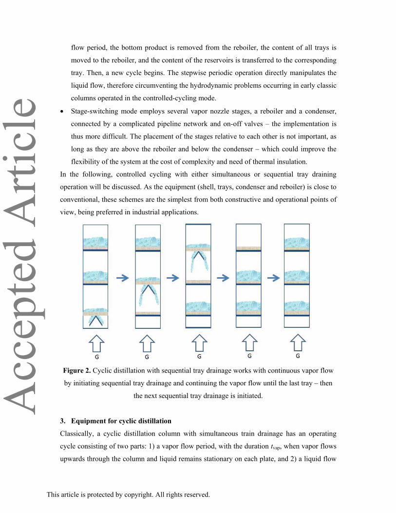
• With a special tray design (shown in Figure 2), using cyclic operated perforated sheet or
slate (COPS) type trays it is possible to introduce a new operational principle for periodic
cycling separation based on sequential tray draining, where the trays are emptied
sequentially rather than simultaneously, while the vapor flow is maintained throughout.5,6
• For stepwise periodic operation,7 each tray is fitted with an inlet and an outlet normally
closed by on-off valves and has a side reservoir large enough to contain one tray-holdup –
which makes the setup more expensive. The trays have no downcomers but they can be
completely emptied through their outlet directly into the reboiler. During the vapor-flow
period, the condensate is sequentially collected in the reservoirs. At the end of the vapor-
This article is protected by copyright. All rights reserved.
Acc
epte
d A
rticl
eflow period, the bottom product is removed from the reboiler, the content of all trays is
moved to the reboiler, and the content of the reservoirs is transferred to the corresponding
tray. Then, a new cycle begins. The stepwise periodic operation directly manipulates the
liquid flow, therefore circumventing the hydrodynamic problems occurring in early classic
columns operated in the controlled-cycling mode.
• Stage-switching mode employs several vapor nozzle stages, a reboiler and a condenser,
connected by a complicated pipeline network and on-off valves – the implementation is
thus more difficult. The placement of the stages relative to each other is not important, as
long as they are above the reboiler and below the condenser – which could improve the
flexibility of the system at the cost of complexity and need of thermal insulation.
In the following, controlled cycling with either simultaneous or sequential tray draining
operation will be discussed. As the equipment (shell, trays, condenser and reboiler) is close to
conventional, these schemes are the simplest from both constructive and operational points of
view, being preferred in industrial applications.
Figure 2. Cyclic distillation with sequential tray drainage works with continuous vapor flow
by initiating sequential tray drainage and continuing the vapor flow until the last tray – then
the next sequential tray drainage is initiated.
3. Equipment for cyclic distillation
Classically, a cyclic distillation column with simultaneous train drainage has an operating
cycle consisting of two parts: 1) a vapor flow period, with the duration tvap, when vapor flows
upwards through the column and liquid remains stationary on each plate, and 2) a liquid flow
This article is protected by copyright. All rights reserved.
Acc
epte
d A
rticl
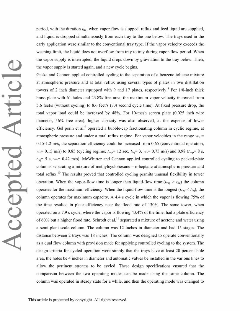
eperiod, with the duration tliq, when vapor flow is stopped, reflux and feed liquid are supplied,
and liquid is dropped simultaneously from each tray to the one below. The trays used in the
early application were similar to the conventional tray type. If the vapor velocity exceeds the
weeping limit, the liquid does not overflow from tray to tray during vapor-flow period. When
the vapor supply is interrupted, the liquid drops down by gravitation to the tray below. Then,
the vapor supply is started again, and a new cycle begins.
Gaska and Cannon applied controlled cycling to the separation of a benzene-toluene mixture
at atmospheric pressure and at total reflux using several types of plates in two distillation
towers of 2 inch diameter equipped with 9 and 17 plates, respectively.8 For 1/8-inch thick
brass plate with 61 holes and 23.8% free area, the maximum vapor velocity increased from
5.6 feet/s (without cycling) to 8.6 feet/s (7.4 second cycle time). At fixed pressure drop, the
total vapor load could be increased by 48%. For 10-mesh screen plate (0.025 inch wire
diameter, 56% free area), higher capacity was also observed, at the expense of lower
efficiency. Gel’perin et al.9 operated a bubble-cap fractionating column in cyclic regime, at
atmospheric pressure and under a total reflux regime. For vapor velocities in the range wv =
0.15-1.2 m/s, the separation efficiency could be increased from 0.65 (conventional operation,
wv= 0.15 m/s) to 0.85 (cycling regime, tvap= 12 sec, tliq= 3, wv= 0.75 m/s) and 0.98 (tvap= 8 s,
tliq= 5 s, wv= 0.42 m/s). McWhirter and Cannon applied controlled cycling to packed-plate
columns separating a mixture of methylcyclohexane – n-heptane at atmospheric pressure and
total reflux.10 The results proved that controlled cycling permits unusual flexibility in tower
operation. When the vapor-flow time is longer than liquid-flow time (tvap > tliq) the column
operates for the maximum efficiency. When the liquid-flow time is the longest (tvap < tliq), the
column operates for maximum capacity. A 4.4 s cycle in which the vapor is flowing 75% of
the time resulted in plate efficiency near the flood rate of 130%. The same tower, when
operated on a 7.9 s cycle, where the vapor is flowing 43.4% of the time, had a plate efficiency
of 60% but a higher flood rate. Schrodt et al.11 separated a mixture of acetone and water using
a semi-plant scale column. The column was 12 inches in diameter and had 15 stages. The
distance between 2 trays was 18 inches. The column was designed to operate conventionally
as a dual flow column with provision made for applying controlled cycling to the system. The
design criteria for cycled operation were simply that the trays have at least 20 percent hole
area, the holes be 4 inches in diameter and automatic valves be installed in the various lines to
allow the pertinent streams to be cycled. These design specifications ensured that the
comparison between the two operating modes can be made using the same column. The
column was operated in steady state for a while, and then the operating mode was changed to
This article is protected by copyright. All rights reserved.
Acc
epte
d A
rticl
ecycling. For conventional operating mode, the column had a very narrow operating range.
Maximum efficiency was obtained at a feed rate of 1.25 gal/min and a reflux ratio of 3.8. The
average tray efficiency was 49.5 %. When the operation was changed from conventional to
cycled, it was possible to put twice or more material through the cycled column at efficiencies
comparable to those for conventional operation. Moreover, the tray temperatures started to
drop off, which means that the separation was improving. The benefits of cycled operation are
thus increased throughput and improved separation. Another effect of controlled cycling was
a somewhat broader operating range. Even though the authors confirmed that higher
efficiency can be obtained at semi-plant scale level, they also observed problems with
maintaining simultaneous draining of liquid from the different trays in columns with more
than a dozen trays.11 The lowest trays drained completely before the upper trays started to
drain. This behavior was later rationalized by simulations of Larsen and Kümmel.12 Schrodt et
al.11 concluded that to avoid this draining problem, a maximum of 10 trays may be used or
some pressure equalization device must be mounted. To solve the problem of the incomplete
separation between liquid and vapor flows, Furzer proposed the use an external manifold to
equalize the tray pressures during flow switching intervals.13,14 In this way a more uniform
liquid holdup distribution could be achieved. The main disadvantage of the manifold was that
vapor could bypass the plates during the vapor flow period. However, for an exponentially
varying area manifold the decrease of the separating ability (observed with constant or
linearly varying area) was controllable, and a favorable increase in separating ability could be
obtained. In order to overcome the problem of liquid mixing during the liquid flow period,
Szony and Furzer presented a new tray design for periodic cycling of distillation columns.15
The new tray design consisted of a sieve plate and inclined surfaces which introduced an
effective liquid time delay. Simulations of periodically cycled columns predicted
improvements in column performance of more than 200% for systems with nonlinear
equilibrium curves. Experiments distilling methanol-water mixtures have verified those
predictions for periodic cycling with a single plate. Although the predicted efficiencies of
200% were not realized due to vapor movement hindering the tray action, a wide range of
operating conditions provided good overall column efficiencies of 140%.
For many years, it was difficult to make Cannon’s classical realization produce theoretical
performance. Many attempts were made to approach the theoretical limit. Even with manifold
and special devices on the trays to delay the liquid, satisfactory performance could not be
made in distillation. For stripping and absorption it is easier to obtain theoretical performance.
By the mid-1980s the most promising realizations were those of Baron,7 Hentrich and
This article is protected by copyright. All rights reserved.
Acc
epte
d A
rticl
eVogelpohl,16 and Matsubara.17
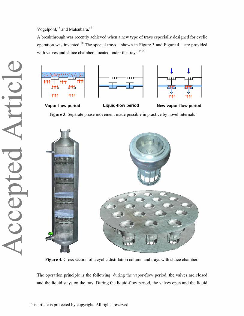
A breakthrough was recently achieved when a new type of trays especially designed for cyclic
operation was invented.18 The special trays – shown in Figure 3 and Figure 4 – are provided
with valves and sluice chambers located under the trays.19,20
Vapour-flow period Liquid-flow period Vapour-flow periodVapor-flow period Liquid-flow period New vapor-flow period Figure 3. Separate phase movement made possible in practice by novel internals
Figure 4. Cross section of a cyclic distillation column and trays with sluice chambers
The operation principle is the following: during the vapor-flow period, the valves are closed
and the liquid stays on the tray. During the liquid-flow period, the valves open and the liquid
This article is protected by copyright. All rights reserved.
Acc
epte
d A
rticl
eflows from the tray to the sluice chamber below. When another vapor-flow period begins, the
sluice chamber is opened and the liquid flows to the empty tray below. By using this type of
tray there are no complications related to the increased number of trays.
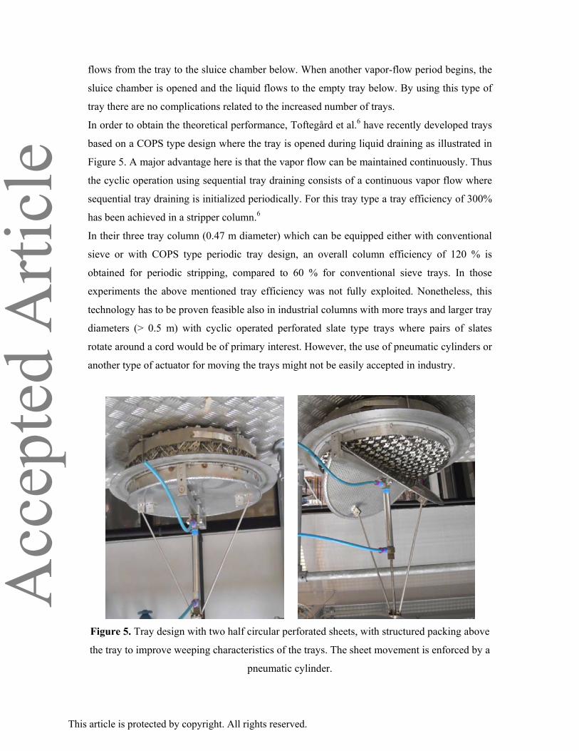
In order to obtain the theoretical performance, Toftegård et al.6 have recently developed trays
based on a COPS type design where the tray is opened during liquid draining as illustrated in
Figure 5. A major advantage here is that the vapor flow can be maintained continuously. Thus
the cyclic operation using sequential tray draining consists of a continuous vapor flow where
sequential tray draining is initialized periodically. For this tray type a tray efficiency of 300%
has been achieved in a stripper column.6
In their three tray column (0.47 m diameter) which can be equipped either with conventional
sieve or with COPS type periodic tray design, an overall column efficiency of 120 % is
obtained for periodic stripping, compared to 60 % for conventional sieve trays. In those
experiments the above mentioned tray efficiency was not fully exploited. Nonetheless, this
technology has to be proven feasible also in industrial columns with more trays and larger tray
diameters (> 0.5 m) with cyclic operated perforated slate type trays where pairs of slates
rotate around a cord would be of primary interest. However, the use of pneumatic cylinders or
another type of actuator for moving the trays might not be easily accepted in industry.
Figure 5. Tray design with two half circular perforated sheets, with structured packing above
the tray to improve weeping characteristics of the trays. The sheet movement is enforced by a
pneumatic cylinder.
This article is protected by copyright. All rights reserved.
Acc
epte
d A
rticl
e
4. Hydrodynamics
The performance of cyclic distillation with simultaneous tray drainage is reduced if the
assumptions of no liquid flow during the vapor-flow period and no liquid mixing during the
liquid-flow period are not fulfilled. A number of experimental and theoretical studies
investigated the applicability of these assumptions. Duffy and Furzer considered a single sieve
plate column operated with periodic cycling.21 They developed a mathematical model
assuming zero weeping rate and plug flow of liquid during the liquid drain period.
Experimentally, no weeping could only be obtained by introducing baffles to control fluid
oscillations on the plate. Experimental measurements of the ratio of the slopes of the
equilibrium and operating lines, the Murphree plate efficiency, the fraction of the liquid
holdup transferred per cycle, and the separation factor X on a computer controlled column
provided the first reliable confirmation of the improvements in separating ability, predicted by
the theory. Furzer studied the fluid flow in a distillation column, by measurements of the
discrete residence time distribution.22 The column (100 mm in diameter) was fitted with 5
sieve plates of 14.8% free area with a 6.1 mm hole diameter on a 635 mm plate spacing. An
analysis of the discrete residence time distribution yielded the parameters in the (2S) model
that describes the fluid flow. The author concluded that modifications to the column internals
were required to alter these parameters, if the maximum separation improvements were to be
obtained. In a follow-up paper, Furzer modeled a periodically cycled plate column, where a
liquid bypass described the nonideal liquid draining.23 A numerical solution over a wide range
of parameters provided a closed envelope of feasible solutions. A region of this envelope
enclosed favorable operating values of the parameters, while the other region is unfavorable.
Measurements of the parameters for nonideal liquid draining in a 600 mm diameter column
fitted with sieve plates lead to predictions of only small improvements in separation
performance. Modifications of internals were required to move the parameters into a more
favorable position in the solution envelope. Goss and Furzer studied both fluid mixing and the
mass transfer separations of mixtures of methylcyclohexane and n-heptane under periodically
cycled conditions in a five plate distillation column, 100 mm in diameter.24 Both the fluid
mixing and mass transfer could be successfully analyzed using the (2S) model to describe the
liquid movement in the column. Only moderate improvements in separation could be obtained
with sieve plates and packed sieve plate columns operated in cycling mode.
In order to investigate the non-ideal liquid mixing, a system consisting of a plate column was
modeled to allow the generation of the discrete residence time distribution.25 The parameters
This article is protected by copyright. All rights reserved.
Acc
epte
d A
rticl
ein the model were evaluated by measurements of entrainment, holdup, and the step response
of the column under direct computer control. A least-squares minimization technique
provided confirmation of the modeling procedures. Larsen and Kümmel described a model for
controlled cycling in tray columns.12 Gas phase dynamics and hydrodynamic relations were
included in the proposed model. The model contains total and component mass balance,
energy balance, hydraulics and pressure drop equations. Gas phase dynamics was found to
play an important role for cyclic operation of distillation columns, whereas the effect of gas
phase dynamics can be ignored for absorption columns. In a 5-tray distillation column
reasonable separation between liquid and vapor flow periods could be achieved, but with
increasing number of trays the switch-over from one period to another becomes less ideal. For
a ten tray column the flow situation is unacceptable. The simulations also showed that the
plug flow condition in the liquid flow period is most difficult to satisfy in the top and bottom
of the column. The risk of flooding on some trays, and other trays running dry, increases
when the numbers of trays increases. The hydrodynamic behavior may be improved by
changing the geometry of some of the trays. Hydrodynamics of liquid holdup in periodically
cycled plate towers were also modeled, simulated, and experimentally confirmed.26,27 The
model developed was applied to the prediction of the holdup distribution and the investigation
of hydrodynamic problems. An effective manifold arrangement was proposed to minimize the
uneven liquid draining encountered in previous experimental studies.
5. Mathematical models and solution methods
The first models for cyclic distillation were developed at a time when the available computing
power was low and expensive. Consequently, drastic assumptions that were employed lead to
limited accuracy of the results. Up to the mid-1980s most published solution algorithms used
very limited models, e.g. where feed only was allowed on the top tray or the point efficiency
had to be unity, or the thermodynamic relations were linear. Linear models may provide
analytical results that enhance process understanding, and are often adequate for describing
stripping, absorption and high purity distillation. In contrast, when nonlinearities (e.g. the
thermodynamic relations) have to be taken into account as in most distillation processes,
analytical results are seldom available hence graphical or numerical methods have to be relied
on instead. Clearly, this gain in accuracy is at the expense of losing the analytical results.
SIMULATION MODELS
Statistical models. For a bubble-cap fractionating column operated in a cyclic regime, at
This article is protected by copyright. All rights reserved.
Acc
epte
d A
rticl
eatmospheric pressure and under total reflux, Gel’perin et al.9 derived a statistical model which
describes the influence of the vapor velocity in the column, of the duration of the vapor
period, and of the duration of the liquid period on efficiency of separation. The efficiency of
separation was evaluated from mean efficiency of every plate which was calculated from
measured data. They varied the vapor period time from 6 to 12 s and liquid period time from 1
to 7 s. The mean vapor velocity in the free column section varied between 0.1 and 1.6 m/s.
From the experimental data they obtained a linear regression equation which adequately
described the process at a 5% significance level.
Linear models. Stationary profile methods were presented by Chien et al.,28 Duffy and
Furzer,21 and Baron et al.7 These models were formulated in matrix notation and used Laplace
transformation for obtaining solutions. Instead of Laplace transformation, matrix
manipulation tools may be used directly as is commonly done in control theory. In this way,
arbitrarily complex linear models may be formulated. Typical assumptions are:21 linear
equilibrium; vapor of constant composition entering the bottom plate during vapor flow
period; and liquid feed supplied to the top plate. The closed form involves solution matrices
suitable for rapid calculation on a computer. Dale and Furzer used the Zakian's method to
invert the Laplace transform of the time response.29 For a 5-plate column, they compared the
accuracy and computing time of the Zakian's method and Runge-Kutta-Merson algorithm.
They concluded that Zakian’s method would be preferable, unless exceptional accuracy was
required. It should be remarked that the computational power available today would certainly
favor numerical integration algorithms.
Non-linear models. The first treatments of non-linear models was to simulate the system in
dynamic mode until stationary operation was attained. However, this may require simulation
of many flow periods, since convergence of the dynamic nonlinear processes model to the
periodic state may be particularly time-consuming. Sommerfeld et al.30 performed analog
computer simulations of a controlled cycling rectification to determine the effect of local
point efficiency, slope of equilibrium lines, amount of liquid dropped during the liquid flow
period, and other parameters on the overall column and individual plate efficiencies. They
showed that cyclic operation leads to improved separation ability. Total reflux was
considered, while distillation with intermediate feed stream was not investigated.
Toftegård and Jorgensen modified the integration method of Petzold in order to obtain an
efficient algorithm for dynamic simulation of controlled cycled chemical processes.31 The
authors tested the method by solving a binary separation in a controlled cycled column with
three ideal trays and feed entering on the middle tray, a reboiler and a condenser. Constant
This article is protected by copyright. All rights reserved.
Acc
epte
d A
rticl
erelative volatility was considered. The liquid period was assumed to have negligible duration.
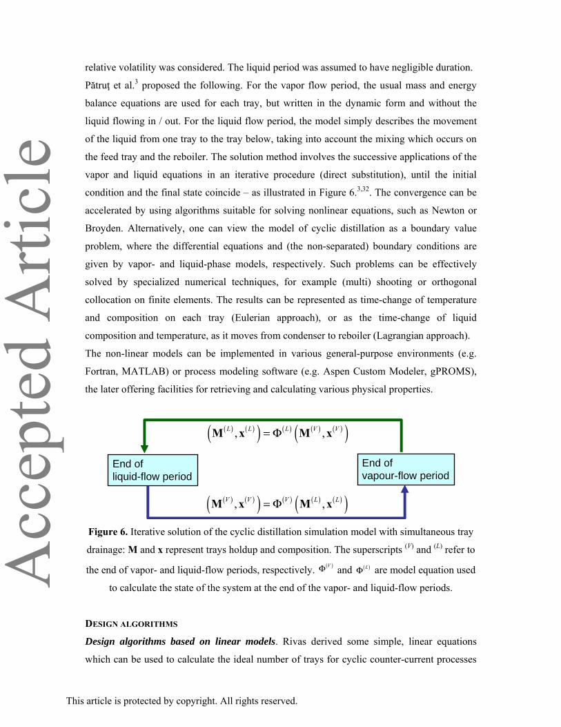
Pătruţ et al.3 proposed the following. For the vapor flow period, the usual mass and energy
balance equations are used for each tray, but written in the dynamic form and without the
liquid flowing in / out. For the liquid flow period, the model simply describes the movement
of the liquid from one tray to the tray below, taking into account the mixing which occurs on
the feed tray and the reboiler. The solution method involves the successive applications of the
vapor and liquid equations in an iterative procedure (direct substitution), until the initial
condition and the final state coincide – as illustrated in Figure 6.3,32. The convergence can be
accelerated by using algorithms suitable for solving nonlinear equations, such as Newton or
Broyden. Alternatively, one can view the model of cyclic distillation as a boundary value
problem, where the differential equations and (the non-separated) boundary conditions are
given by vapor- and liquid-phase models, respectively. Such problems can be effectively
solved by specialized numerical techniques, for example (multi) shooting or orthogonal
collocation on finite elements. The results can be represented as time-change of temperature
and composition on each tray (Eulerian approach), or as the time-change of liquid
composition and temperature, as it moves from condenser to reboiler (Lagrangian approach).
The non-linear models can be implemented in various general-purpose environments (e.g.
Fortran, MATLAB) or process modeling software (e.g. Aspen Custom Modeler, gPROMS),
the later offering facilities for retrieving and calculating various physical properties.
( ) ( )( ) ( ) ( ) ( )( ), ,V V V L L= ΦM x M x
( ) ( )( ) ( ) ( ) ( )( ), ,L L L V V= ΦM x M x
End of liquid-flow period
End of vapour-flow period
Figure 6. Iterative solution of the cyclic distillation simulation model with simultaneous tray
drainage: M and x represent trays holdup and composition. The superscripts (V) and (L) refer to
the end of vapor- and liquid-flow periods, respectively. ( )VΦ and ( )LΦ are model equation used
to calculate the state of the system at the end of the vapor- and liquid-flow periods.
DESIGN ALGORITHMS
Design algorithms based on linear models. Rivas derived some simple, linear equations
which can be used to calculate the ideal number of trays for cyclic counter-current processes
This article is protected by copyright. All rights reserved.
Acc
epte
d A
rticl
efor a given set of operating conditions.33 The model assumed: negligible column vapor holdup
in comparison to liquid holdup; constant vapor flow rates during vapor flow period; constant
and equal liquid holdup for rectifying section and stripping section; binary mixture;
equilibrium stages; linear equilibrium relationship; and plug flow of liquid from stage to stage
during the LFP. The first five conditions are the usual simplifying assumptions made when
designing ideal conventional columns. The linear equilibrium relationship condition is valid
for processes such as absorption and stripping. The condition related to plug flow of liquid
from stage to stage during the liquid flow period states that there is no mixing of liquid from
two adjacent plates during the liquid flow period. However, some mixing is inevitable and
this will tend to decrease the separating ability of the column. The authors also showed that
the performance can be predicted by using operating line and equilibrium equations, similarly
to conventional distillation. However, deriving the operating line equation is not trivial as the
liquid and vapor compositions are both unknown functions of time. In order to obtain an
analytical solution, Rivas used the following properties of the composition profiles:33 during
the vapor flow period, the composition of the more volatile component decays with time
without maximum, minimum, or inflection points; the differential equation for the plate above
the reboiler can be solved because the composition of the vapor flowing into this plate is
constant, which is true only for infinite reboiler holdup. It was assumed that over a small
range of composition the equilibrium curve is given by a straight line. For a very large
column, the profile of the top plate must approach a straight line since the composition at the
beginning and at the end of the period are nearly equal. After deriving the equation that
represents the concentration profile on the stages, an equation to calculate the number of
stages necessary for a given separation was derived.
For the linear equilibrium case, Toftegård and Jorgensen computed stationary profiles for
periodic cycled separation columns.34 They wrote the mass balance in a dimensionless, matrix
form. The authors also propose a tray-by-tray design method, applied to the purification of a
mixture following the linear equilibrium relationship y = 2·x, from a mole fraction of 0.01 to
0.0001. A similar matrix representation was used by Chien et al.28 The computational method
for obtaining the theoretical number of stages employs two pseudo-equilibrium curves on a
modified McCabe Thiele diagram.
Design algorithms based on nonlinear models. Toftegård and Jorgensen wrote the nonlinear
model of the binary, cyclic distillation in a form that is suitable for finding the number of
trays necessary to achieve a certain separation.35 Their model is based on a Rayleigh type
equation for the reboiler. At the pseudo-steady state, the liquid concentration at the end of the
This article is protected by copyright. All rights reserved.
Acc
epte
d A
rticl
eVFP must correspond to the bottom product concentration. Then, knowing the length of the
VFP allows one to integrate backwards in time until the concentration at the beginning of the
VFP is reached. With a mass balance, this can yield the liquid concentration on the tray above
at the end of the VFP. Then, a similar integration is done (backwards in time) on the tray
above the reboiler, followed by mole balance considerations to give the liquid composition on
the next tray. Continuing in this way until the top product purity has been exceeded allows the
determination of the number of stages. The feed stage is then selected as the tray where the
difference between the liquid concentration and the feed stream is the smallest. This approach
can be seen as the method of steps for solving a delay-differential equations model, as
described by Pătruţ et al.3 Comparing the results obtained using the nonlinear and linear
design model, the authors concluded that the assumptions used for deriving the linear model
are not valid. Thus, the number of trays necessary to perform the separation of an equimolar
benzene-toluene mixture into 95% pure product is 8 for periodic operation and 16 for
conventional operation, while the linear model of Rivas predicted 5.3 stages.33
Maleta et al.18 included the mass transfer kinetics in the form of local point efficiency. They
present a simple graphical method for designing tray columns operated in cyclic mode. The
model of a binary column consists in: mass balance of light component on the tray during the
vapor-flow period; mass balance during liquid-flow period; mass transfer kinetics included by
means of the local point efficiency; equilibrium between vapor phase and liquid phase. For
linear equilibrium relationship, the equations can be solved analytically to find the
concentration profiles on each stage. Other issues considered were: cell model of the
imperfect flow and residence time distribution (RTD) experiments.
Pătruţ et al.3 formulated the design model as a set of delay-differential equations, describing
the change of liquid state as it moves backwards in time, from reboiler to condenser, being in
contact with the vapor coming from the tray below. The time needed to go up the column
from the reboiler (given bottoms composition) to the condenser (known distillate
composition) gives the total number of trays, taking into account the vapor period.
A key problem is that all these models were developed by various groups using different
programming languages. As so far none of these models is available in process simulators, it
is extremely important that the software vendors will work on including these models in the
commercial process simulators (e.g. Aspen Plus, ChemCAD, gPROMS).
6. Control of cyclic distillation columns
The first papers about cyclic distillation specify the reboiler duty and the time for the vapor-
This article is protected by copyright. All rights reserved.
Acc
epte
d A
rticl
eand liquid-flow periods as the control variables. McWhirter and Cannon controlled the boilup
rate by a pressure regulator on the steam used to heat the still.10 In order to control vapor and
liquid flows, the columns were provided with solenoid valves controlled by a cycle
timer.4,10,36. It should be noted that this is an open loop operation mode, as vapor-flow and
liquid-flow periods are handled without any information from the process. On contrary,
during closed loop operation, process measurements (e.g. concentration or temperature) are
used to modify the cycling in order to obtain the desired concentration of a specific stream.
Matsubara et al.37 considered the periodic control of a continuous multistage distillation
column. For an objective function including separating efficiency and the utility cost, the
authors note that optimality is achieved when the flow rates of feed, vapor, reflux, distillate
and bottoms and the holdups of condenser and reboiler are variable.
Experimental feedback control of a periodically cycled gas stripping column has been
implemented by Dale and Furzer.38 The control scheme investigated was variable period
control, where the vapor flow period was adjusted from cycle to cycle to control the exit
liquid composition leaving the bottom plate of the column. The control algorithm was direct
digital control incorporating proportional and integral terms, in incremental form: the average
composition of the bottom product is subtracted from the desired value to yield the control
error for that cycle. The control input - duration of the vapor flow period for the next cycle - is
computed using that error. After computer simulation, experiments were performed on a 5
plates, 2 ft diameter column. Air was used to strip ammonia from a 0.3M aqueous solution. A
20 kW fan was switched on and off by means of mechanically linked butterfly valves.
Periodic cycling of the liquid was achieved by pumping feed liquid from the feed tank either
back or to the column, by means of a 3-way valve. The pump operated continuously,
eliminating the need for rapid switching it on and off. In order to ensure a constant amount of
liquid was added to the column during each cycle, a differential pressure cell measured the
changing pressure drop across the top plate. This solved a major problem in periodic cycling -
that of maintaining the correct liquid flow inputs. The composition was measured by a
conductivity cell in the exit liquid flow stream. The measured conductivity value was
averaged over one cycle, although a one-cycle delay resulted from this method. Temperature
was also measured, and a correction was applied to the conductivity. Temperatures and
pressure drops across several plates were also monitored. The vapor flow period was limited
to a range of 10 sec (to allow for sufficient time to pump the liquid and drain from the column
past the conductivity cell) to 10 min 25 sec (limited time which could be counted on the
system clock). A two term direct computer control (DCC) algorithm programmed on a remote
This article is protected by copyright. All rights reserved.
Acc
epte
d A
rticl
ereal-time minicomputer adjusted the vapor flow period to study the rejection of a step
disturbance in the feed. Computer simulations of the control scheme using a basic model of
the periodically cycled stripping column gave reasonable agreement with the parameters
tested. Further refinement of the model in describing column hydrodynamics is required, for
accurate simulation. The authors mention a number of interesting problems posed by periodic
operation: overall material and mass balances must be maintained; in contrast to conventional
operation, where only small changes of flow rates are required, periodic operation modifies
the inputs between minimum and maximum values; it is necessary to control not only the
actual flow rate, but also the total amount of flow of each input (this is particularly important
during the liquid drain period); there must be stable hydrodynamic operation of the column;
the liquid drain time must be carefully chosen to maintain the desired holdup; some method of
product composition measurement is necessary. According to Schrodt,39 both instantaneous
and averaged measurements are necessary, as the control mechanism must maintain both the
repeating pattern of the instantaneous variables and their average.
Matsubara et al.17 proposed the use of relay feedback for control of plate columns noting that
the task of periodic control of a chemical process is to keep the process in the neighborhood
of a periodic state. In principle one has three ways of generating a periodic state.
1. Forced oscillation. The output of a periodic function generator is applied to the process as
the control input and as a result a forced oscillation will appear in the process.
2. Self-excited oscillation due to internal feedback. All the control inputs are always held
constant. Even in such a situation a self-excited oscillation may sometimes appear in the
process due to the internal recycle of material / heat caused by dispersion, mixing, etc.
3. Self-excited oscillation due to external feedback. Appropriate output variables of the
process are measured and fed back to a controller which generates the control input. Then,
a self-excited oscillation will appear in the process with the external feedback loop.
The first and second control schemes are open-loop controls, while the third is a closed-loop
control. The advantage of a closed-loop periodic control scheme is that it can suppress the
effects of disturbances that enter the process, while an open loop periodic control cannot.
Matsubara et al.17 analyzed what for long appeared to be the best possible control, provided
product composition could be measured on-line without dynamic effects. They used the
simulation example of Dale and Furzer38 to which the relay feedback periodic control was
applied. The strategy, proposed in an earlier paper by the same group,37 is to measure the
product concentration: when it reaches the desired value, the vapor flow is interrupted and
product is taken out. Then the liquid flow period follows and then the next vapor flow period
This article is protected by copyright. All rights reserved.
Acc
epte
d A
rticl
eand so forth. This simple strategy produces perfect control action, provided that concentration
can be monitored continuously without delays. Thus, the realization of Matsubara’s results
may not be easy in practice. Performing computer simulations for a column with four stages,
stage Murphree efficiency ε = 0.8 and feed composition disturbances, the forced oscillation
scheme resulted in significant deviations of the product purity from the required value.
Adding an averaged output regulator resulted in much smaller deviations which quickly died
out. The forced oscillation scheme using relay feedback gave perfect composition control,
although this could be unattainable in real applications due to imperfect mixing and
measurement inaccuracies.
Both the controller of Matsubara et al.17 and of Dale and Furzer38 are SISO controllers. This
gives some limits in the control performance, for example fluctuations in the measured
concentration following changes in the feed concentration. A multi-input multi-output
(MIMO) controller should be able to take into account the interactions between all
measurements and all manipulated variables. Furthermore, MIMO controller designed from a
properly formulated model automatically may include a feed forward component, such that
some fluctuations are reduced if not eliminated. However to design a MIMO controller it is
necessary to have an adequate model of the process dynamics. Toftegård and Jørgensen
published preliminary studies on identification and control of a periodic cycled distillation
column with 9 trays for separation of benzene/toluene.40 They aimed at a multi-variable
adaptive multi-input single-output controller. The controller uses the vapor flow period length
as controller output to control distillate composition. More measurements (3 in total) than
controller outputs means that more information on the process is used, that is, it corresponds
to a build-in feed forward part. The tested controller was adaptive, meaning that it finds the
process parameters itself, also if these change during operation.
In a simulation study considering the separation of an ethanol / n-propanol mixture, Pătruţ et
al.3 suggested a control scheme in which temperatures near the top and the bottom of the
column are measured at the end of vapor-flow period. Then, the reflux amount and vapor flow
rate are adjusted by a discrete time PI-controller, similarly to the well-known L-V control
structure of conventional distillation.
While the design and control of cyclic distillation has been largely explored and investigated
with good results, the optimization topic is practically missing from the open literature.
7. Industrial applications
Schrodt et al.11 were the first who investigated the applicability of the cyclic operation mode
This article is protected by copyright. All rights reserved.

Acc
epte
d A
rticl
eto industrial scale distillation. They separated a mixture of acetone and water using a semi-
plant scale column. The column was 12 inches in diameter and had 15 stages. The distance
between trays was 18 inches. Their column was designed to operate conventionally as a dual
flow column with provision made for applying controlled cycling to the system. The design
criteria for cycled operation were simply that the trays have at least 20 per cent hole area, the
holes be 4 inches in diameter and automatic valves be installed in the various lines to allow
the pertinent streams to be cycled. These design specifications insured that a comparison
between the two operating modes can be made using the same column. Uniform flow of
liquid from the trays during liquid-flow period was not achieved. The higher efficiencies can
be achieved by cycling operation only if plug flow can be obtained. Plug flow means that the
liquid that flows from a tray to the tray below is not mixed with the liquid from the tray
above. The observations indicated that only columns with up to 10-12 trays could be operated
without serious flow problems. The pressure was measured at the bottom of the column and
the temperatures on trays 1 and 3 (numbered from the bottom of column to the top). The cycle
times varied from 2.3 to 8 seconds for liquid-flow period and from 5 to 10 seconds for vapor-
flow period. The ratio between vapor-flow time and liquid-flow time varied from 1 to 4. It
was noticed that the maximum efficiency obtained in cyclic mode was lower than the
maximum efficiency obtained in conventional operating mode.
They reached the conclusion that the promises of earlier small-scale efforts were not
completely realized in the larger column. Simple modification of existing equipment will
result in some substantial improvement as long as the number of trays is less than 12. In order
to achieve plug flow it will be necessary to modify the tray design or to install some type of
pressure-equalizing manifold on columns with more than 10 or 12 trays. However the promise
of 100% efficiency increases and 2 to 3 times capacity increases is still valid. It was possible
to distill to the same degree of purity 3 gal/min of feed while cycling as compared to 1.25
gal/min for conventional operation.11
Nowadays, when the tray design has improved, the advantages of cyclic operated distillation
columns can be seen at industrial scale. Since 2005, MaletaCD implemented (built and
installed commercial scale plants) several cyclic distillation columns with 5 up to 42 trays and
column diameters of 0.4-1.7 m.32 Among them, a cyclic distillation column with simultaneous
tray drainage is implemented at industrial scale in the food industry (Lipnitsky Alcohol Plant,
Ukraine). The cyclic distillation column (15 stages, 0.5 m diameter) is used to increase the
alcohol concentration to a higher grade. The plant production is of 20 m3/day ethanol food
grade.18. The diluted feed stream (3.29 mol% alcohol) is supplied on the top tray of the cyclic
This article is protected by copyright. All rights reserved.
Acc
epte
d A
rticl
edistillation column (stripping column), while direct steam injection is used in the bottom of
the column. The specification for the ethanol concentration in the top distillate varies between
13 and 24 mol%, with a typical value of 18.25 mol%, while the concentration of ethanol in
the bottom product must not exceed 0.004 mol%. Moreover, an industrial scale dividing wall
column using cyclic operation (42 trays, 1.5/1.7 m diameter, capacity of 25 m3/hr) was built
in 2014 by MaletaCD for a plant processing kerosene and white spirit (see maletacd.com for
additional information).
Just as in the case of other PI technologies (e.g. dividing-wall column), the chemical industry
is reluctant in adopting new technologies due to various perceived issues such as: difficult
process control, unavailability of cyclic distillation models in process simulators, reliability of
moving parts to sustain the cyclic operation, etc.
8. Conclusions
Cyclic distillation can bring new life to old distillation columns, by simply changing the
internals and operating mode, and therefore providing key benefits, such as: increased column
throughput, lower energy requirements, as well as better separation performance. Moreover,
the separate phase movement of the vapor and liquid phases throughout the column provides
more degrees of freedom which contribute to excellent process control and trouble-free
operation. The literature review and industrial reports available indicate several benefits of
cyclic operation over the conventional one:
• High tray efficiencies (140-300% Murphree efficiency), so that at the same vapor flow
rate a required purity can be obtained using fewer trays – hence reduced capital costs.
• Higher throughput and equipment productivity as compared to conventional distillation.
• Reduced energy requirements, so that a required purity can be achieved with lower vapor
flow rates, at the same number of trays – thus lowering operating costs by 30-50%.
• Increased quality of the products is possible due to the higher separation efficiency.
• The cyclic distillation configuration and operation allows larger liquid holdups that can be
beneficial for reactive distillation concepts, such as catalytic cyclic distillation.19
Cyclic distillation has many promising prospects, but in order to flourish further, the future
research on this topic has to address the main challenges faced by this PI technology:
• Investigate the possible combinations of cyclic distillation with other PI technologies: e.g.
cyclic distillation in dividing-wall column potentially integrated with reactive distillation.
• Expand the use of cyclic operation to azeotropic, extractive, and reactive distillation.
This article is protected by copyright. All rights reserved.
Acc
epte
d A
rticl
e• Find new applications that prove the advantages in case of difficult industrial separations;
e.g. close boiling components, high purity products, significantly increased capacity.
• Develop advanced process control techniques to address any tight purity requirements or
feed variability – abundant knowledge on distillation control is available and can be used.
• Further develop and implement shortcut and rigorous design and simulation methods
(usable in process simulators) – that incorporate hydrodynamic models, for example by
making use of today’s computing power and recent advances in CFD.
• Include reliable models for design and control of cyclic distillation in process simulators.
• Development reliable tray designs that allow a true separation of phase movements and
assurance of worldwide availability from a large number of equipment manufacturers.
• Investigate the application of the cyclic operated perforated sheet or slate type trays with
sequential tray drainage also in reactive separations where the packing on the trays could
incorporate the catalyst on the desired trays.
References
1. Kiss AA, Advanced distillation technologies - Design, control and applications, Wiley,
Chichester, UK, 2013.
2. Kiss AA, Distillation technology - Still young and full of breakthrough opportunities, J.
Chem. Technol. Biot. 89: 479-498 (2014).
3. Pătruţ C, Bildea CS, Lita I and Kiss AA, Cyclic distillation - Design, control and
applications, Sep. Purif. Technol. 125: 326-336 (2014).
4. Cannon MR, Controlled cycling improves various processes, Ind. Eng. Chem. 53:629-629
(1961).
5. Toftegård B, and Jorgensen SB, Operational principles for periodic cycled operation,
IChemE Symposium Series No. 104:A473-A482 (1987).
6. Toftegård B, Clausen CH, Jørgensen SB and Abildskov J, A new realization of periodic
cycled separation, Ind. Eng. Chem. Res., Article in press (2016).
7. Baron G, Wajc S, and Lavie R, Stepwise periodic distillation - I. Total reflux operation.
Chem. Eng. Sci. 35:859-865 (1980).
8. Gaska RA and Cannon MR, Controlled cycling distillation in sieve and screen plate
towers, Ind. Eng. Chem.53:630-631 (1961).
9. Gel’perin NI, Polotskii LM and Potapov TG, Operation of a bubble-cap fractionating
column in a cyclic regime, Chem. Petro. Eng. 11:707-709 (1976).
This article is protected by copyright. All rights reserved.

Acc
epte
d A
rticl
e10. McWhirter JR and Cannon MR, Controlled cycling distillation in a packed-plate column,
Ind. Eng. Chem. 53:632-634 (1961).
11. Schrodt VN, Sommerfeld JT, Martin OR, Parisot PE and Chien HH, Plant-scale study of
controlled cyclic distillation, Chem. Eng. Sci. 22:759-767 (1967).
12. Larsen J and Kümmel M, Hydrodynamic model for controlled cycling in tray columns,
Chem. Eng. Sci. 34:455-462 (1979).
13. Furzer IA, Steady state flow distributions in a plate column fitted with a manifold, Chem.
Eng. Sci. 35:1291-1298 (1980).
14. Furzer IA, Mass transfer in a periodically cycled plate column fitted with a manifold,
Chem. Eng. Sci. 35:1299-1305 (1980).
15. Szonyi L and Furzer IA, Periodic cycling of distillation-columns using a new tray design,
AIChE J. 31:1707-1713 (1985).
16. Hentrich P, and Vogelpohl A, Untersuchung von Verweil-zeitverhalten und Ruchver-
mischung der Flussigkerisstromung intermitterend betriebener Gegenstrommilonnen,
Verfahrenstechnik, 14:806-808 (1980).
17. Matsubara M, Nishimura Y, Watanabe N and Onogi K, Relay feedback periodic control
of plate columns, Chem. Eng. Sci. 37:753-758 (1982).
18. Maleta VN, Kiss AA, Taran VM and Maleta BV, Understanding process intensification in
cyclic distillation systems. Chem. Eng. Process. 50:655-664 (2011).
19. Pătruţ C, Bildea CS and Kiss AA, Catalytic cyclic distillation – A novel process intensi-
fication approach in reactive separations, Chem. Eng. Process. 81: 1-12 (2014).
20. Maleta BV, Shevchenko A, Bedryk O and Kiss AA, Pilot-scale studies of process
intensification by cyclic distillation, AIChE J. 61:2581-2591 (2015).
21. Duffy GJ, Furzer IA, Mass transfer on a single sieve plate column operated with periodic
cycling, AIChE J. 24:588-598 (1978).
22. Furzer IA, The discrete residence time distribution of a distillation column operated with
microprocessor controlled periodic cycling, Can. J. Chem. Eng. 56:747-750 (1978).
23. Furzer IA, Periodic cycling of plate columns: Mass transfer with nonideal liquid draining,
AIChE J. 25:600-609 (1979).
24. Goss DW, Furzer IA, Mass transfer in periodically cycled plate columns containing
multiple sieve plates, AIChE J. 26:663-669 (1980).
25. Furzer IA and Duffy GJ, Periodic cycling of plate columns: Discrete residence time
distribution, AIChE J. 22:118-1125 (1976).
26. Thompson MF and Furzer IA, Hydrodynamic modeling for liquid holdups in periodically
This article is protected by copyright. All rights reserved.
Acc
epte
d A
rticl
ecycled plate columns, AIChE J. 30:496-500 (1984).
27. Thompson MF and Furzer IA, Hydrodynamic simulation of periodic cycled plate
columns, AIChE J. 31:1275-1287 (1985).
28. Chien HH, Sommerfeld JT, Schrodt VN, Parisot PE, Studies of controlled cyclic
distillation: II. Analytical transient solution and asymptotic plate efficiency, Sep. Sci.
1:281-317 (1966).
29. Dale EB and Furzer IA, An application of Zakian's method to solve the dynamics of a
periodically cycled plate column, Chem. Eng. Sci. 29:2378-2380 (1974).
30. Sommerfeld JT, Schrodt VN, Parisot PE and Chien HH, Studies of controlled cyclic
distillation: I. Computer simulation and the analogy with conventional operation, Sep. Sci.
1:245-279 (1966).
31. Toftegård B and Jørgensen SB, An integration method for dynamic simulation of cycled
processes, Comput. Chem. Eng. 13:927-930 (1989).
32. Kiss AA and Bildea CS, Revive your columns with cyclic distillation, Chem. Eng. Prog.
111:21-27 (2015).
33. Rivas OR, An analytical solution of cyclic mass transfer operations, Ind. Eng. Chem.
16:400-405 (1977).
34. Toftegård B and Jørgensen SB, Stationary profiles for periodic cycled separation columns:
linear case, Ind. Eng. Chem. Res., 27:481-485 (1988).
35. Toftegård B and Jørgensen SB, Design algorithm for periodic cycled binary distillation
columns. Ind. Eng. Chem. Res. 26:1041-1043 (1987).
36. Kurimoto H, Matsubara M, Watanabe N and Shimizu K, State-switching operation for
enhanced periodic distillation, Chem. Eng. Sci. 44:1449-1451 (1989).
37. Matsubara M, Nishimura Y, Watanabe N and Shimizu K, Periodic control of continuous
distillation processes, Chem. Eng. Sci. 30:1075-1083 (1975).
38. Dale EB and Furzer IA, Periodic cycling of plate columns: Control simulations and
experiments, Chem. Eng. Sci. 33:905-911 (1978).
39. Schrodt VN, Unsteady-state processing, Ind. Eng. Chem. Res. 59:58-65 (1967).
40. Toftegård B, and Jørgensen SB, Identification of periodic cycled distillation for control
purposes, Rairo-Automatique-Productique Informatique Industrielle-Automatic Control
Production Systems. 23:573-582 (1989).
This article is protected by copyright. All rights reserved.