Embed Size (px)
DESCRIPTION
technical design
Citation preview

Sponsored by the Department of Energy
Submitted towards partial fulfillment of the requirements for
The Design Review Subcontest
Northern Arizona University
Wind Turbine Technical Design Report The Collegiate Wind Competition

1
Table of Contents
1.0 Design Objective ..................................................................................................................................... 3
2.0 Design Overview ..................................................................................................................................... 3
2.1 Blades .................................................................................................................................................. 3
2.2 Hub Design .......................................................................................................................................... 5
2.3 Nosecone ............................................................................................................................................ 5
2.4 Yawing System .................................................................................................................................... 6
2.5 Integrated Nacelle Design ................................................................................................................... 6
2.6 Mainframe .......................................................................................................................................... 7
2.7 Base ..................................................................................................................................................... 8
2.8 Tower .................................................................................................................................................. 8
2.9 Battery ................................................................................................................................................. 9
2.10 Electronic Controls ............................................................................................................................ 9
3.0 Design Team .......................................................................................................................................... 11
4.0 Modeling and Testing ........................................................................................................................... 12
4.1 Rotor/Blade Design Modeling ........................................................................................................... 12
4.2 Blade and Hub Design Modeling ....................................................................................................... 13
4.3 Tower Design Modeling .................................................................................................................... 14
4.4 Nacelle Flow Modeling ...................................................................................................................... 15
4.5 Base Design Modeling ....................................................................................................................... 15
5.0 Engineering Diagrams ........................................................................................................................... 15
6.0 Engineering Specifications .................................................................................................................... 16
6.1 Technical Specifications .................................................................................................................... 17
6.3 Turbine Component Dimensions ...................................................................................................... 18
6.4 Power Curve Specifications ............................................................................................................... 19
7. 0 References ............................................................................................................................................ 19
8.0 Appendices ............................................................................................................................................ 20
8.1 Appendix A: Team Member Roles .................................................................................................... 20

2
List of Tables Table 1: Tower Analyses Summary ............................................................................................................. 14
Table 2: Technical Specifications ................................................................................................................ 17
Table 3: Major Turbine Component Dimensions ........................................................................................ 18
List of Figures
Figure 1: Blade Profile ................................................................................................................................... 4
Figure 2: Manufactured hub ......................................................................................................................... 5
Figure 3: Nosecone Design ............................................................................................................................ 5
Figure 4: Yawing System ............................................................................................................................... 6
Figure 5: Rapid Prototyped Nacelle .............................................................................................................. 6
Figure 6: Mainframe and Bracket ................................................................................................................. 7
Figure 7: Base ................................................................................................................................................ 8
Figure 8: Guy Wire Fixture ............................................................................................................................ 8
Figure 9: Schottky Three Phase Bridge Rectifier ......................................................................................... 10
Figure 10: Top Level Algorithm Diagram of the MSP430 code ................................................................... 11
Figure 11: Testbench setup with Motorsolver Dyno Kit equipment .......................................................... 12
Figure 12: Blade Mold Design ..................................................................................................................... 13
Figure 13: Turbine Assembly ....................................................................................................................... 16
Figure 14: Initial Rotor Power Curve ........................................................................................................... 19
3
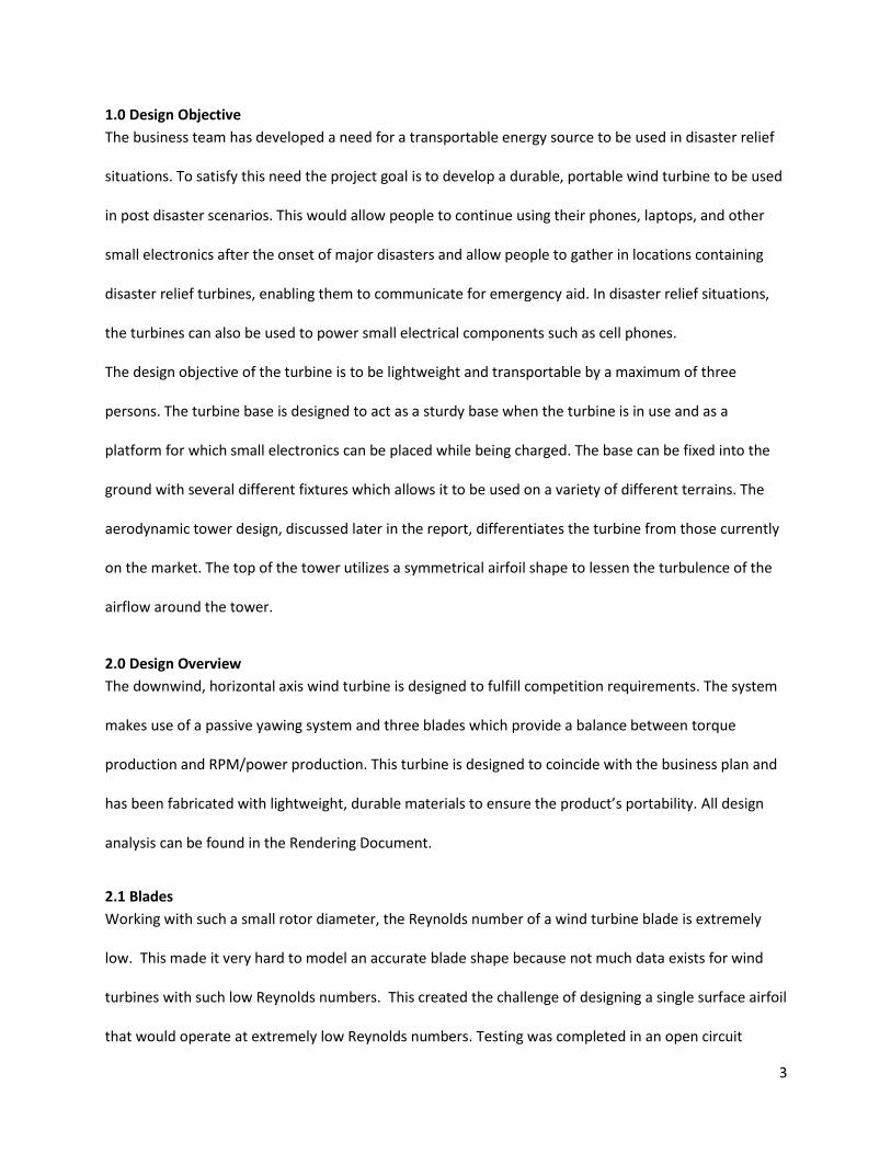
1.0 Design Objective
The business team has developed a need for a transportable energy source to be used in disaster relief
situations. To satisfy this need the project goal is to develop a durable, portable wind turbine to be used
in post disaster scenarios. This would allow people to continue using their phones, laptops, and other
small electronics after the onset of major disasters and allow people to gather in locations containing
disaster relief turbines, enabling them to communicate for emergency aid. In disaster relief situations,
the turbines can also be used to power small electrical components such as cell phones.
The design objective of the turbine is to be lightweight and transportable by a maximum of three
persons. The turbine base is designed to act as a sturdy base when the turbine is in use and as a
platform for which small electronics can be placed while being charged. The base can be fixed into the
ground with several different fixtures which allows it to be used on a variety of different terrains. The
aerodynamic tower design, discussed later in the report, differentiates the turbine from those currently
on the market. The top of the tower utilizes a symmetrical airfoil shape to lessen the turbulence of the
airflow around the tower.
2.0 Design Overview
The downwind, horizontal axis wind turbine is designed to fulfill competition requirements. The system
makes use of a passive yawing system and three blades which provide a balance between torque
production and RPM/power production. This turbine is designed to coincide with the business plan and
has been fabricated with lightweight, durable materials to ensure the product’s portability. All design
analysis can be found in the Rendering Document.
2.1 Blades
Working with such a small rotor diameter, the Reynolds number of a wind turbine blade is extremely
low. This made it very hard to model an accurate blade shape because not much data exists for wind
turbines with such low Reynolds numbers. This created the challenge of designing a single surface airfoil
that would operate at extremely low Reynolds numbers. Testing was completed in an open circuit

4
subsonic wind tunnel to obtain lift and drag data of a flat plate at low Reynolds numbers and determine
the stall characteristics. A flat plate, having a chord length of 0.5 inches and a length of ten inches, was
designed with a slight camber for testing. Data is recorded for the normal and axial forces acting on the
thin airfoil while wind velocity was steadily increasing. This data is recorded automatically in a LabVIEW
program, then the total lift and drag force of the thin airfoil was calculated using the normal and axial
forces and the angle of attack.
This information provided the knowledge to be able to run a code utilizing the Blade Element
Momentum (BEM) theory to obtain an optimized blade shape [1]. This blade shape contains a certain
twist and chord length that was optimized using the BEM code generated. A slight camber is also
applied to the airfoil so that the blades will obtain enough torque to get started. The final airfoils are
the S834 and CP-080-050-GN (single surface airfoil), which are used in the final design. From these two
airfoils, the blade design was optimized using two different software packages and the Blade Elemental
Momentum (BEM) theory. Initially two, three, four, and six bladed systems were considered for
competition; however, a three bladed system was chosen for the final design because of its ability to cut
in at low wind speeds and run at high rpms. The two programs used, BLADED and FAST, determined the
forces that are acting on certain blade sections. The final blade profile is shown in Figure 1 and was
analyzed using
BEM, FAST, and
BLADED.
The final blade
shape is designed
around the operating Reynolds number from wind speeds varying from 2-17 m/s. In low wind speeds,
Figure 1: Blade Profile

5
the team used a single surface airfoil design to improve the turbine efficiency by having the blades cut-in
sooner and produce more power.
2.2 Hub Design
The blade root was designed to fit exactly
into the hub shown in Figure 2. The three
slots in the hub are where each blade root
will fit and will be held in place with a hub
plate and bolt. The borehole of the hub
will be connected to the drivetrain using a
collet. The hub design used Aluminum
stock, which is cheap, strong, and easy to
manufacture.
2.3 Nosecone
To minimize the effects of vortices that shed off of the rotor, a nosecone is included to provide an
aerodynamic structure to the design. This nosecone is a
simple design which can be clipped onto the hub and is
easy to assemble and cheap to manufacture. This design
is a simple hemispherical shape that lets the air flow
smoothly over the back of the turbine. This design is
shown in Figure 3.
Figure 2: Manufactured hub
Figure 3: Nosecone Design

6
2.4 Yawing System
The turbine utilizes a passive yawing system which allows the blades to be directed into the wind. The
yawing system design consists of two single row, deep groove ball
bearings, a three phase slip ring, a threaded base plug, a yaw
sleeve, an upper yaw plug, and a yaw shaft. A sectional view of
the yawing system can be seen in Section 1 of the Rendering
Document. This image shows how all of the components in this
system fit together. The yaw shaft is threaded into a plug at the
base of the system. The two bearings and plastic bearing spacers
sit on the shaft and an aluminum sleeve fits over the top with a
plug press fit into the top. Figure 4 shows the yawing system with
the mainframe, slip ring, and generator attached.
2.5 Integrated Nacelle Design
A fared tower section encases the yawing system and allows for less turbulent wind flow across the
turbine tower. This minimizes vortex shedding as wind flows over the trailing edge of the tower,
reducing inefficiencies as the turbine blades pass behind the
tower. This aerodynamic casing has been integrated into the
nacelle design to create a sleek and aesthetically appealing
design.
The nacelle sits above the fared tower section and was designed
around the dimensions of the mainframe and the hub. The nacelle
is only slightly larger than the hub to lessen inefficiencies as air
flows over the nacelle and to the blades. A removable door has
been built into the top half of the nacelle to ensure that
components can be properly placed and to allow components to
Figure 4: Yawing System
Figure 5: Rapid Prototyped Nacelle

7
be fully inspectable. The integrated nacelle design has been rapid prototyped using ABS and Ultem
plastic. Ultem was used due ease of access of material and will not be used in the market turbine. Figure
5 shows the nacelle just after it was rapid prototyped. The two bottom components were secured
together with JB weld and a coat of paint was applied to the whole nacelle (not shown).
2.6 Mainframe
The mainframe is designed to withstand all loading and act as a completely rigid structure while being
small enough to fit behind the shadow of the hub. The mainframe has been constructed from 16 gauge
sheet metal and cut to shape using a CNC milling machine. FEA proved 16 gauge sheet metal to be
sufficient to withstand the necessary loads, this analysis can be seen in Section 2 of the Rendering
Document. The piece was then bent into
shape to provide structural rigidity. This
component was then painted with a cold-
galvanizing compound to prevent corrosion.
This design makes use of two components to
make accessing the generator simple and to
allow the mainframe to be used for a direct
drive system and a system which utilizes a
gearbox. The generator is first mounted onto
a bracket which can then be mounted onto to the mainframe. These two components can be seen in
Figure 6. The mainframe supports the provided Great Planes Ammo GPMG 5225 motor, a three phase
slip ring, the nacelle structure, and provides mounting for the passive yaw system. This system is bolted
to the yaw plug located at the top of the yawing system and fastened to the nacelle.
Figure 6: Mainframe and Bracket
8
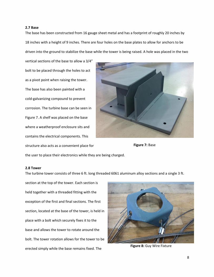
2.7 Base
The base has been constructed from 16 gauge sheet metal and has a footprint of roughly 20 inches by
18 inches with a height of 9 inches. There are four holes on the base plates to allow for anchors to be
driven into the ground to stabilize the base while the tower is being raised. A hole was placed in the two
vertical sections of the base to allow a 3/4”
bolt to be placed through the holes to act
as a pivot point when raising the tower.
The base has also been painted with a
cold-galvanizing compound to prevent
corrosion. The turbine base can be seen in
Figure 7. A shelf was placed on the base
where a weatherproof enclosure sits and
contains the electrical components. This
structure also acts as a convenient place for
the user to place their electronics while they are being charged.
2.8 Tower
The turbine tower consists of three 6 ft. long threaded 6061 aluminum alloy sections and a single 3 ft.
section at the top of the tower. Each section is
held together with a threaded fitting with the
exception of the first and final sections. The first
section, located at the base of the tower, is held in
place with a bolt which securely fixes it to the
base and allows the tower to rotate around the
bolt. The tower rotation allows for the tower to be
erected simply while the base remains fixed. The
Figure 7: Base
Figure 8: Guy Wire Fixture
9
final section, located at the top of the tower, has a threaded plug press fit into the top where the yaw
shaft threads into the tower. A guy wire fixture sits on the final tower couple and can be seen in Figure
8. This fixture is where the guy wires are attached to the tower and is angled at the ideal guy wire angle
of 60⁰ with respect to the ground. A cold-galvanizing compound covers the guy wire fixture to prevent
corrosion.
2.9 Battery
Although not required for the competition, the battery bank is a key component of the business plan.
The UB12120 12 V 10 Ah battery was selected to demonstrate the battery bank application for the
competition. This battery was selected based on storage, temperature, humidity, extreme weather
conditions and time of the year data. It will be used in Midwest and Coastal areas during hurricane and
tornado seasons. From these areas, the turbine system is expected to obtain up to 25 Wh at optimum
wind speed with 2 days of autonomy. It is also designed to operate between 30 ⁰F – 75 ⁰F with humidity
accounted for. It is a 12 V system battery that can be connected to the power output to store unused
power for later use.
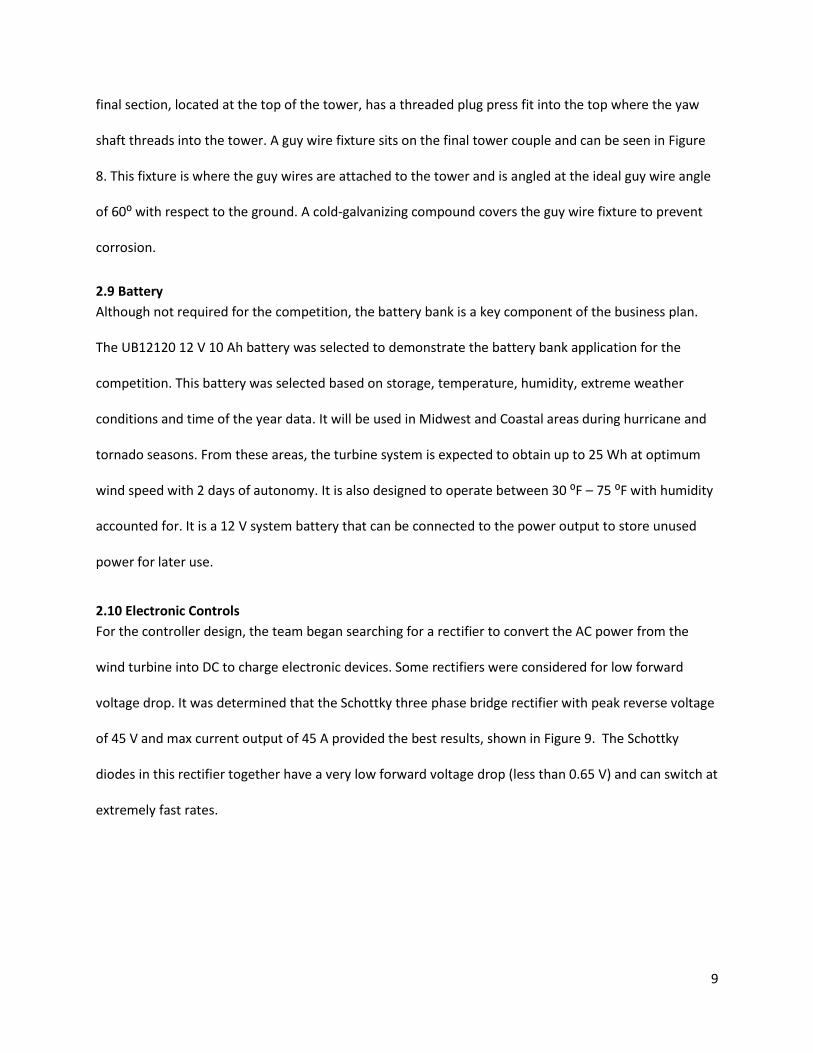
2.10 Electronic Controls
For the controller design, the team began searching for a rectifier to convert the AC power from the
wind turbine into DC to charge electronic devices. Some rectifiers were considered for low forward
voltage drop. It was determined that the Schottky three phase bridge rectifier with peak reverse voltage
of 45 V and max current output of 45 A provided the best results, shown in Figure 9. The Schottky
diodes in this rectifier together have a very low forward voltage drop (less than 0.65 V) and can switch at
extremely fast rates.
10
In order to regulate the output voltage to 5 V into the grid, the
team designed a boost converter circuit that could withstand 20
V and 15 A, since previous generator tests results showed that
this was an obtainable range. Three iterations of these circuit
designs were made as well as revisions of them by implementing
them on homemade printed circuit boards. This custom process
started with using photo paper and a laser jet printer to print
out the basic design. Next, the team cleaned the clad board and
cut it to dimensions, which is noted on Table 3. A household iron
was used to iron the ink into the clad board. Once the ink was sealed on the board, the team put it into a
bath of muriatic acid. This created a reverse of the PCB and left the ink where it was. Finally, it was
bathed in acetone to remove the ink, which gave the team their final PCB layout. After that, they were
able to drill the mounting holes for the electrical components. This design can be found on the final
Printed Circuit Board (PCB) schematic, shown in Section 4 of the Rendering Document.
The final PCB schematic, shown in Section 4 of the Rendering Document, has the MSP430 as the
microcontroller. This was determined as best suited for this application due to its interrupt capabilities
and extensive low power mode options. A top level diagram of its operation is shown in Figure 10.
Several iterations have been made to create a final design that is determined to be capable in handling
the electrical brake of the wind turbine. This design has three phase power flow into the PCB from the
motor where it is then loaded onto resistors. Brakes are handled by the MSP430 using bipolar junction
transistors (BJT’s) for each phase of the circuit. These transistors are useful for handling high AC current,
which helps to control the motor’s desired frequency. The outgoing three phase power will then flow
through the slip rings and to the components.
Figure 9: Schottky Three Phase Bridge Rectifier

11
Figure 10: Top Level Algorithm Diagram of the MSP430 code
3.0 Design Team
The NAU team consists of five different sub-teams that all have a wide range of experience and talents.
There are three engineering teams in charge of designing and constructing the overall turbine, a
business team dedicated to creating the business plan, and a wind market issues team which
collaborates for the Market Issues Presentation. The three engineering teams consist of a blade and hub
design team, a balance of system and testing team, and a controls and charging team. The business
team is full of business and market plan specialists that have created a business plan and will present
the turbine market and company at competition. There is also a market issues team that will work on
12
completing the Market Issues Presentation. A complete list of all the engineering team members and
their project roles is shown in Appendix A.
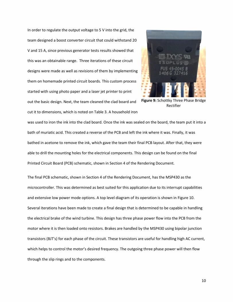
4.0 Modeling and Testing
Motor testing was completed using testing procedures designed specifically to measure the AC
voltage, AC current, DC voltage and DC power waveforms from the motor. A testbench and dSPACE
ControlDesk software were used to control the permanent-magnet DC (PMDC) motor and MATLAB
software to produce desired plots. Figure 11 shows the equipment used for motor testing. In this
set-up, an armature voltage can be applied to the PMDC motor and allow the user to acquire
information. This was used to
obtain the motor’s rotational
speed and carefully regulate
the motor in order to maintain
a current below 4.5 A, as this is
the maximum operating
current for this setup.
4.1 Rotor/Blade Design Modeling
The blade’s Reynolds number was on the order of 104 which is extremely low for finding lift and drag
on an airfoil. Leading the team to design a 3 bladed design which has a very long chord length and fits
perfectly within the constraints of the competition rules and regulations. The chord length and twist of
the blade root elements were exaggerated to provide the optimal amount of lift to get the blades to cut-
in. The main objective of the blade design was to take up as much rotor plane area as possible to get as
much power out of the wind as possible. The stresses on the blades and hub are included in the
rendering document which was found using ANSYS Workbench FEA software.
Figure 11: Testbench setup with Motorsolver Dyno Kit equipment
13
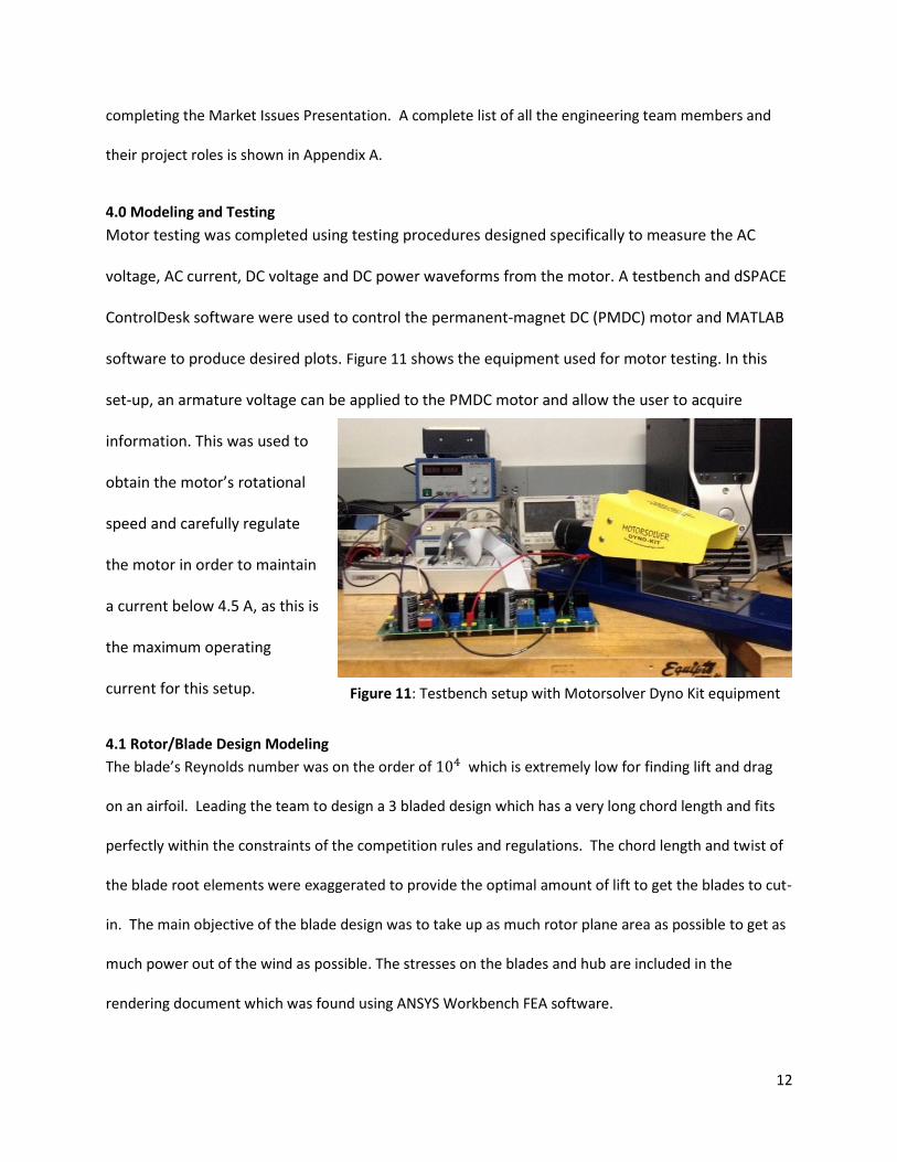
Manufacturing of the blade design incorporated a mold that was completed in SolidWorks. This mold is
made up of two sections that have been rapid prototyped to be able to form the very thin shape of the
blade profile. These two halves come together to make a single blade. One-half of the mold can be seen
in Figure 12.
An extremely thin and strong design
was needed to ensure that the blades
could be made as thin as possible.
Various iterations of the blade design
were rapid prototyped to see how the
design would look and perform in the
wind tunnel. The team sought out the
design of carbon fiber blades, over 3D
printing, so that the blades could meet
the dimensional criteria the team
needed. The blade profile could
not be rapid prototyped because the blades were so thin and that the machine could not generate the
blade tip. A mold was designed in order to create the exact geometry that was needed.
4.2 Blade and Hub Design Modeling
The team iterated through many blade designs which were all modeled through FEA software. The
teams FEA expert was able to accurately determine the factors of safety and other stress concentrations
that occurred on the blades. Using the ANSYS Workbench, the team applied directions of forces,
material properties, and geometry of the designed blade and hub for the rotor. Through this analysis
Figure 12: Blade Mold Design

14
the team was able to inspect each blade element through a fine mesh that was modeled. For the hub,
the highest stress concentrations were located at the edge of the blade root slots. This was because of
the radial force that the blades will reach from the maximum RPM. For the blades, the team was
concerned about the flapwise bending moment forces acting on the blades. These forces proved to
show very slight deflections of 5 millimeters at the tip and factors of safety of 1.5. The described FEA
modeling of the blades and hub is shown in Section 2 of the Rendering Document.
4.3 Tower Design Modeling
Analysis initially completed on the tower showed that the tower exhibited fairly large deflections at the
desired height and diameter. To minimize deflection, guy wires are used to stabilize the tower. In order
to determine the optimal position to reduce buckling deflections, the resultant tension force was placed
at a series of heights initially aligning with tower segment, or 6ft (1.83m), increments. This analysis
found that the ideal guy wire location was at 14ft (4.27m). Bending analysis was completed assuming
the highest stress scenario would be when the tower is raised with a maximum nacelle weight of 60N.
Section 2 of the rendering document shows the tower deflection due to a buckling stress from the
weight of the components up tower.
Table 1 provides a summary of the results obtained from the analyses done. Using the values for
maximum stress, obtained using finite element analysis on the tower design with guy wires, the
minimum factor of safety was found to be 4.2, occurring while raising the tower.
Table 1: Tower Analyses Summary
Analyses With Guy Wire Supports for Max Load
Top Load from Turbine Weight 60 N
Wind Load 100 N
Tower Height 6 m
Maximum Bending Stress 55 MPa
Bending Factor of Safety 4.2
Maximum Buckling Stress 0.4 MPa
Buckling Factor of Safety 180

15
4.4 Nacelle Flow Modeling
Research conducted on faired tower sections for downwind turbines showed that implementing this
design could reduce vortex sheading and decrease loads on the blades. Further analysis was completed
using Solidworks Fluid Flow Simulation to determine an ideal taper angle. Several iterations of this
analysis was completed with differing taper angles to determine which angle would work best at the
rated wind speed of 12 m/s. Based on the results of the velocity flow profile and flow trajectory plots
shown in Section 3 of the Rendering Document, a 12 degree taper angle was found to be the best for
angle for this application. Flow simulations were also done at the cut in and cut out wind speeds of 4
m/s and 17 m/s for the chosen taper angle in order to verify results.
4.5 Base Design Modeling
To ensure that the material of the base would be sufficient to withstand the forces it was exposed to,
analysis was done on the assembled base design in SolidWorks. The individual components of the base
were made out of 16 gauge metal in SolidWorks and were assembled as a single assembly using welds.
The main force that the base must withstand takes place at the pivot point on the base where the tower
bolts to the base. Therefore, the force exerted by the tower under operating conditions was placed
there to analyze the Von Mises stress and the displacement. From the FEA analysis seen in Section 2 of
the Rendering Document, it can be seen that the greatest Von Mises stress is 2.24MPa and the greatest
deflection is 1.82x10⁻²mm. From this data, it was found that 16 gauge sheet metal was sufficient for the
design of the base.
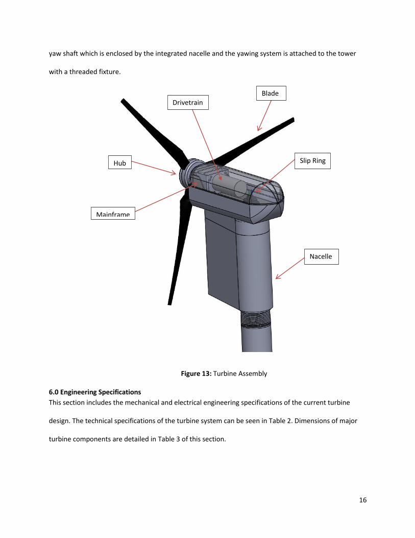
5.0 Engineering Diagrams
An image of the current design configuration is shown in Section 1 of the Rendering Document. This
design displays the complete rotor design, nacelle and other major turbine components in Figure 13.
The assembled figure shows that all of the turbine components have the proper connections. The hub is
connected to the drivetrain through a series of shafts and bolts. The drivetrain and electrical
components sit on the mainframe and transmit power down tower via slip rings. The slip ring sits on the
16
yaw shaft which is enclosed by the integrated nacelle and the yawing system is attached to the tower
with a threaded fixture.
6.0 Engineering Specifications
This section includes the mechanical and electrical engineering specifications of the current turbine
design. The technical specifications of the turbine system can be seen in Table 2. Dimensions of major
turbine components are detailed in Table 3 of this section.
Figure 13: Turbine Assembly
Hub
Blade
Nacelle
Mainframe
Slip Ring
Drivetrain

17
6.1 Technical Specifications
Table 2 lists the technical specifications of the wind turbine system. Two blade options were considered
for design, both of which are listed in the blades row of the technical specifications table.
Table 2: Technical Specifications
Temperature Rating 5 to 122⁰F (-15 to 50 ⁰C)
Swept Area 962.1 in² (6221 cm²)
Rotor Diameter 17.5 in (44.5 cm)
Design Power 14 W at 20 m/s
Weight 35.3 Ib (16 kg)
Shipping Dimensions 20”x18”x10”
Tip Speed Ratio Outboard TSR of 7, Inboard decreases to 5.5
Turbine Controller MSP430 16-bit microcontroller
Blades (3) Carbon Fiber Composite (3) Polycarbonate Composite
Motor Permanent Magnet Brushless In-Runner
Battery 12 V 10 Ah Lead Acid AGM
Airfoil Sections Single Surface AirfoilS834 and CP-080-050-GN

18
6.3 Turbine Component Dimensions
Table 3 displays the dimensions of major turbine components.
Table 3: Major Turbine Component Dimensions
Specifications Value Units
Blade Design
Rotor diameter 17.9 in
Hub diameter 2 in
Yawing System Yaw Shaft Outer Diameter 2.12 in
Tower
Outer Tower Diameter 1.89 in
First three tower section lengths 6 ft ea.
Final tower section length 3 ft
Assembled tower height 21 ft
Mainframe
Length 6 in
Width 2.3 in
Maximum height 2 in
PCB
Length 4.45 in
Width 5.1 in
Maximum height 1.5 in
Battery
Length 5.94 in
Width 3.88 in
Maximum height 3.78 in

19
6.4 Power Curve Specifications
The following graph, shown in Figure 14, displays the power curve for the turbine design that was
completed using NREL’s FAST program to model the turbine design. This data uses the required
dimensions of the blade shapes and also the mass of the design, plotting a power curve from a cut-in
wind speed of around 5 m/s and a cut-out wind speed of 20 m/s. The calculated rated power is
approximately 65 W at a rated wind speed of approximately 12m/s.
Figure 14: Initial Rotor Power Curve
7. 0 References
[1] J.F Manwell, J.G. McGowan, A.L. Rogers, 2009 Wind Energy Explained: Theory, Design and Application
2nd Edition. Wiley Publications. Chapter 3, Section 3.9 pg. 131-13.

20
8.0 Appendices
8.1 Appendix A: Team Member Roles
Name Project Role Responsibilities
Andrew Hoffman Project Manager Team leader, MATLAB, Circuit Analysis and Finances
Carlos Tarango Secretary Spreadsheets, presentations, and PSpice
Ian Mason Assistant Technical Lead Wind Turbine Interface (MSP430 integrated circuit)
Jared Parks Technical Lead Wind Turbine Interface, electrical aspects of the wind turbine
Jonathan Pepper Treasurer Constructing PCB layouts
Mariflor Caronan Rules/Regulation Expert Coordinating info with team members on rules and regulations updates
Nathan Croswell Technical Lead Make sure everything is completed. FAST Program Leader
Devon Martindale Project Manager Directs team to stay on task. Compile Deliverables. FAST secondary lead
Gabriel O'Reilly Machine Design Tech Shaft Design Leader and Machine Design Leader
Norman Khoo FEA/Stress Analysis Lead COSMOS, SolidWorks, ANSYS FEA analysis leader
Chris Feyen Hub Design Lead Hub Designer and Secondary SolidWorks leader.
Kenneth Saxer Computer Coding Lead Software, BEM and SolidWorks Leader
Chris Bozorth Technical Lead Ensures technical aspects of the project are completed correctly.
Melissa Head Project Manager Facilitates communication between engineering and business students.
Kyle Yates Inventory Control Lead Ensures all turbine components fit together and are feasible to manufacture
Anna Manning Software Lead Ensures the design and analysis of turbine components in software are correct. SolidWorks leader
Charles Burge Aerodynamic Specialist Makes certain turbine components are aerodynamic
Ashley Jerome Report and Presentation Lead
Edits documents and ensures that all necessary information is included.