Embed Size (px)
Citation preview
CUSTOMENGINEEREDSWITCHES
Engineered Solutions for The Most Severe Pressure, Vacuum and Temperature Applications
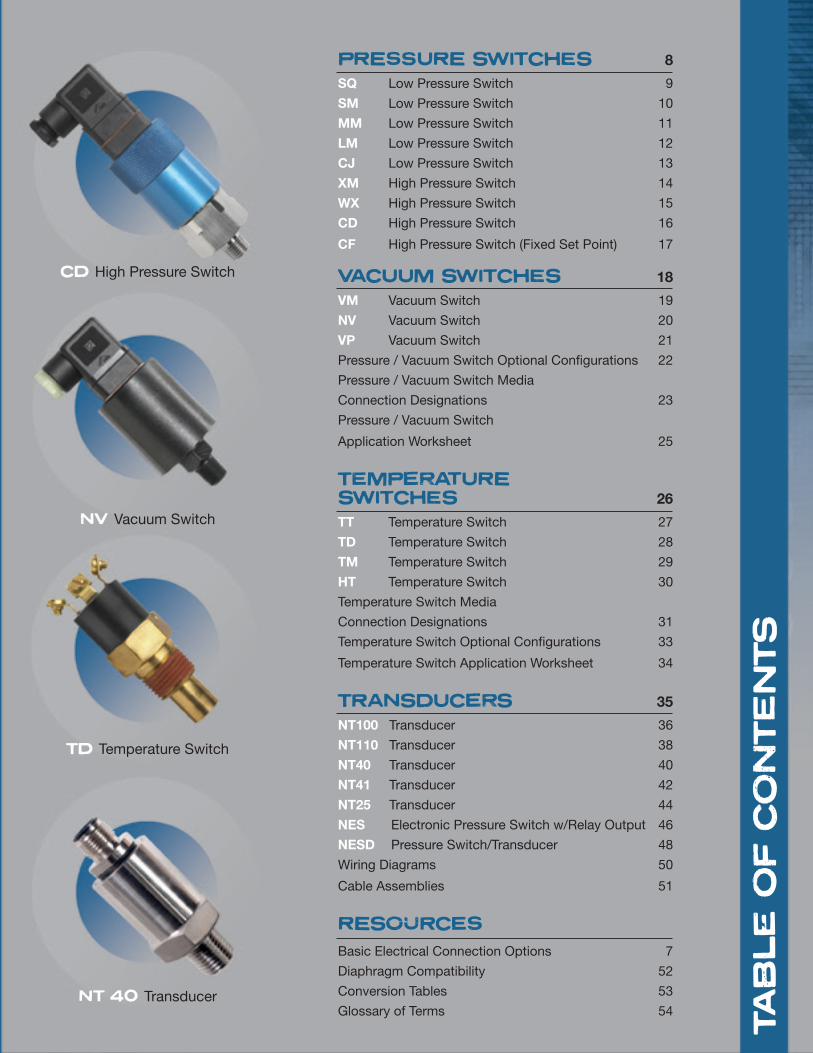
PRESSURE SWITCHES 8
SQ Low Pressure Switch 9
SM Low Pressure Switch 10
MM Low Pressure Switch 11
LM Low Pressure Switch 12
CJ Low Pressure Switch 13
XM High Pressure Switch 14
WX High Pressure Switch 15
CD High Pressure Switch 16
CF High Pressure Switch (Fixed Set Point) 17
VACUUM SWITCHES 18
VM Vacuum Switch 19
NV Vacuum Switch 20
VP Vacuum Switch 21
Pressure / Vacuum Switch Optional Configurations 22
Pressure / Vacuum Switch Media
Connection Designations 23
Pressure / Vacuum Switch
Application Worksheet 25
TEMPERATURESWITCHES 26
TT Temperature Switch 27
TD Temperature Switch 28
TM Temperature Switch 29
HT Temperature Switch 30
Temperature Switch Media
Connection Designations 31
Temperature Switch Optional Configurations 33
Temperature Switch Application Worksheet 34
TRANSDUCERS 35
NT100 Transducer 36
NT110 Transducer 38
NT40 Transducer 40
NT41 Transducer 42
NT25 Transducer 44
NES Electronic Pressure Switch w/Relay Output 46
NESD Pressure Switch/Transducer 48
Wiring Diagrams 50
Cable Assemblies 51
RESOURCES Basic Electrical Connection Options 7
Diaphragm Compatibility 52
Conversion Tables 53
Glossary of Terms 54 TAB
LE OF
CON
TEN
TS
CD High Pressure Switch
NV Vacuum Switch
TD Temperature Switch
NT 40 Transducer
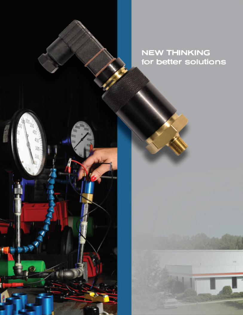
NEW THINKINGfor better solutions
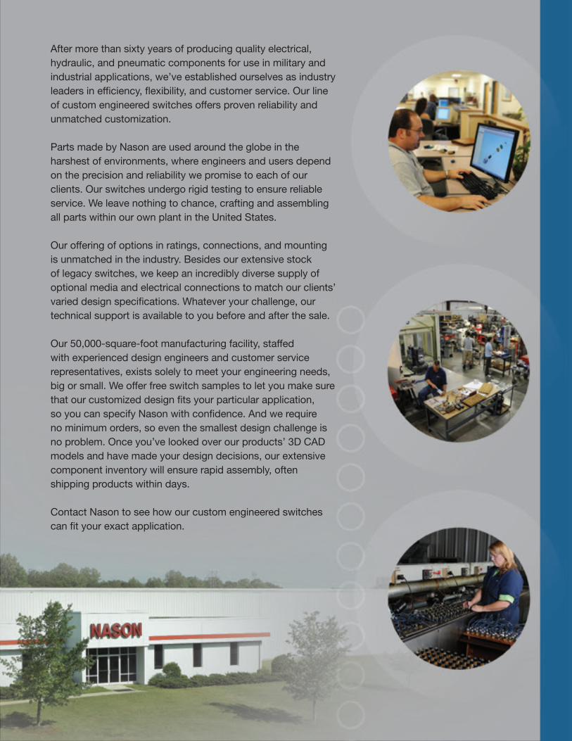
After more than sixty years of producing quality electrical, hydraulic, and pneumatic components for use in military and industrial applications, we’ve established ourselves as industry leaders in efficiency, flexibility, and customer service. Our line of custom engineered switches offers proven reliability and unmatched customization.
Parts made by Nason are used around the globe in the harshest of environments, where engineers and users depend on the precision and reliability we promise to each of our clients. Our switches undergo rigid testing to ensure reliable service. We leave nothing to chance, crafting and assembling all parts within our own plant in the United States.
Our offering of options in ratings, connections, and mounting is unmatched in the industry. Besides our extensive stock of legacy switches, we keep an incredibly diverse supply of optional media and electrical connections to match our clients’ varied design specifications. Whatever your challenge, our technical support is available to you before and after the sale.
Our 50,000-square-foot manufacturing facility, staffed with experienced design engineers and customer service representatives, exists solely to meet your engineering needs, big or small. We offer free switch samples to let you make sure that our customized design fits your particular application, so you can specify Nason with confidence. And we require no minimum orders, so even the smallest design challenge is no problem. Once you’ve looked over our products’ 3D CAD models and have made your design decisions, our extensive component inventory will ensure rapid assembly, often shipping products within days.
Contact Nason to see how our custom engineered switches can fit your exact application.
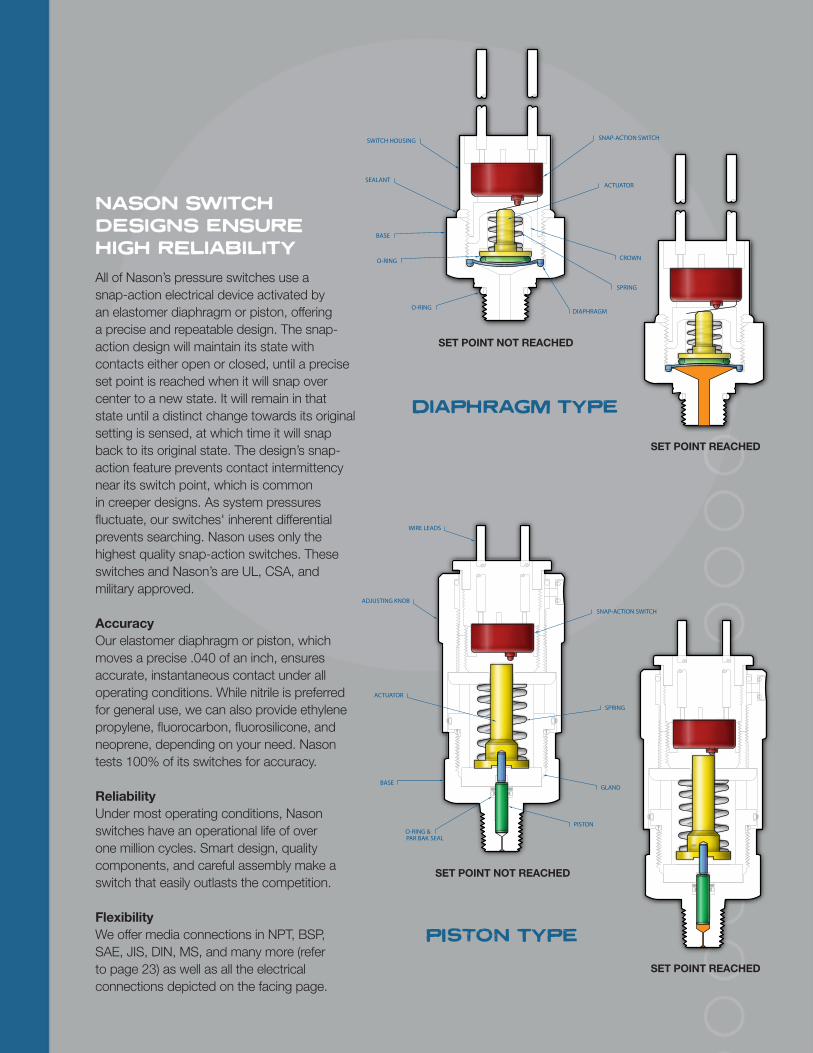
NASON SWITCH DESIGNS ENSURE HIGH RELIABILITYAll of Nason’s pressure switches use a snap-action electrical device activated by an elastomer diaphragm or piston, offering a precise and repeatable design. The snap-action design will maintain its state with contacts either open or closed, until a precise set point is reached when it will snap over center to a new state. It will remain in that state until a distinct change towards its original setting is sensed, at which time it will snap back to its original state. The design’s snap- action feature prevents contact intermittency near its switch point, which is common in creeper designs. As system pressures fluctuate, our switches' inherent differential prevents searching. Nason uses only the highest quality snap-action switches. These switches and Nason’s are UL, CSA, and military approved.
AccuracyOur elastomer diaphragm or piston, which moves a precise .040 of an inch, ensures accurate, instantaneous contact under all operating conditions. While nitrile is preferred for general use, we can also provide ethylene propylene, fluorocarbon, fluorosilicone, and neoprene, depending on your need. Nason tests 100% of its switches for accuracy.
ReliabilityUnder most operating conditions, Nason switches have an operational life of over one million cycles. Smart design, quality components, and careful assembly make a switch that easily outlasts the competition.
FlexibilityWe offer media connections in NPT, BSP, SAE, JIS, DIN, MS, and many more (refer to page 23) as well as all the electrical connections depicted on the facing page.
WIRE LEADS
ACTUATOR
SNAP-ACTION SWITCH
GLAND
SPRING
O-RING & PAR BAK SEAL
ADJUSTING KNOB
PISTON
BASE
SET POINT NOT REACHED
SET POINT REACHED
PISTON TYPE
BASE
SWITCH HOUSING
O-RING
DIAPHRAGM
SEALANT
SNAP-ACTION SWITCH
ACTUATOR
SPRING
CROWN
O-RING
SET POINT NOT REACHED
SET POINT REACHED
DIAPHRAGM TYPE
ELE
CTR
ICA
L C
ONN
EC
TION
OP
TION
S
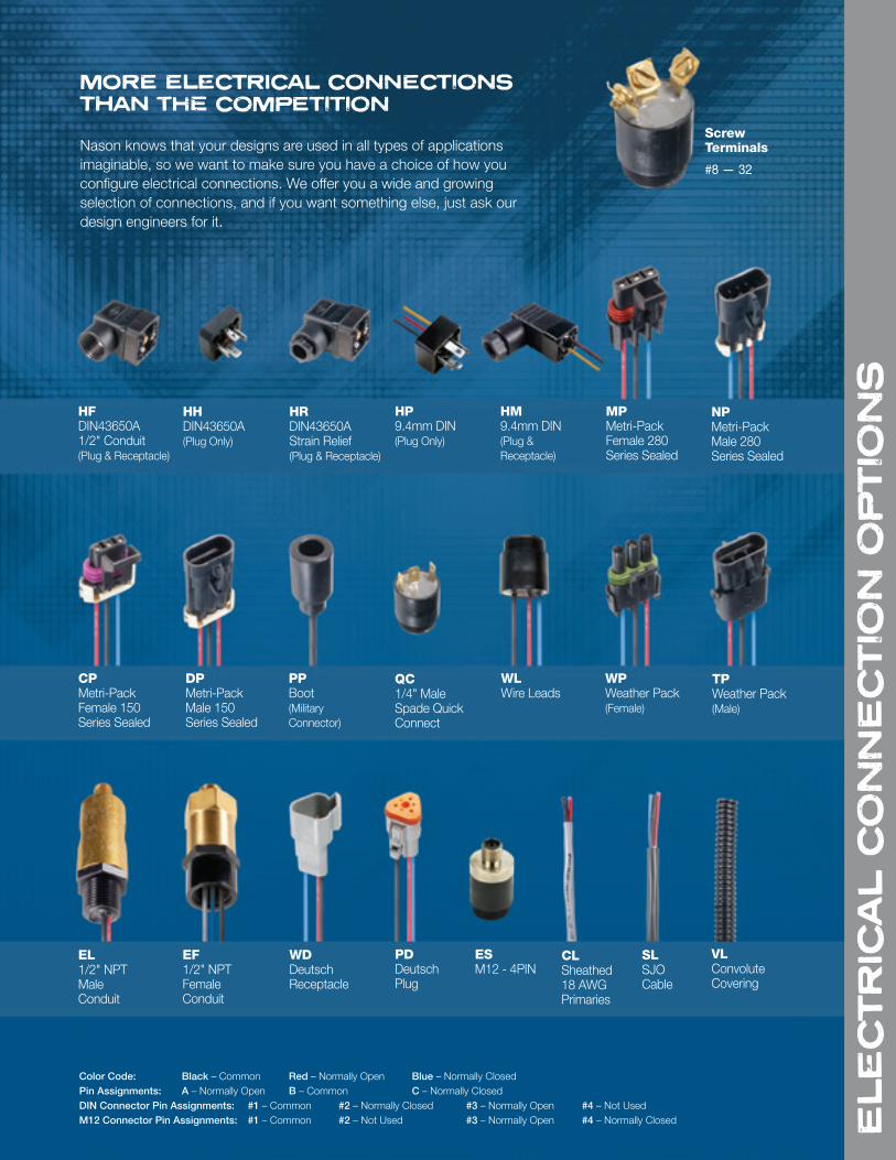
MORE ELECTRICAL CONNECTIONS THAN THE COMPETITION
Nason knows that your designs are used in all types of applications imaginable, so we want to make sure you have a choice of how you configure electrical connections. We offer you a wide and growing selection of connections, and if you want something else, just ask our design engineers for it.
ScrewTerminals
#8 — 32
HFDIN43650A 1/2" Conduit (Plug & Receptacle)
HHDIN43650A (Plug Only)
HRDIN43650A Strain Relief(Plug & Receptacle)
HP9.4mm DIN(Plug Only)
MPMetri-Pack Female 280 Series Sealed
HM9.4mm DIN (Plug & Receptacle)
NPMetri-Pack Male 280 Series Sealed
CPMetri-Pack Female 150 Series Sealed
DPMetri-Pack Male 150 Series Sealed
PPBoot(Military Connector)
QC1/4" Male Spade Quick Connect
WPWeather Pack(Female)
WLWire Leads
TPWeather Pack(Male)
EL1/2" NPT Male Conduit
EF1/2" NPT Female Conduit
WDDeutsch Receptacle
PDDeutsch Plug
SLSJO Cable
CLSheathed 18 AWGPrimaries
VLConvolute Covering
ESM12 - 4PIN
Color Code: Black – Common Red – Normally Open Blue – Normally ClosedPin Assignments: A – Normally Open B – Common C – Normally ClosedDIN Connector Pin Assignments: #1 – Common #2 – Normally Closed #3 – Normally Open #4 – Not UsedM12 Connector Pin Assignments: #1 – Common #2 – Not Used #3 – Normally Open #4 – Normally Closed

8 PRE
SSU
RE S
WIT
CHE
S
PRESSURE SWITCHES
• Low to high pressure switch models with 2 psi to 7500 psi set points
• High-quality snap-action design
• Long-life elastomer diaphragms
• Proven sealed piston sensor on high-pressure models
• Over one million operating cycles
• 100% tested for accuracy
• Models for both pneumatic and hydraulic applications
• Adjustable and factory preset models
• Customizable
• NEMA 4 and 13 available
9
SI
P
RISE1205020
2.2"(56mm)
2.4"(61mm)
1/8-27 NPT
1.0" HEX(25.4mm)
1/4" SPADES
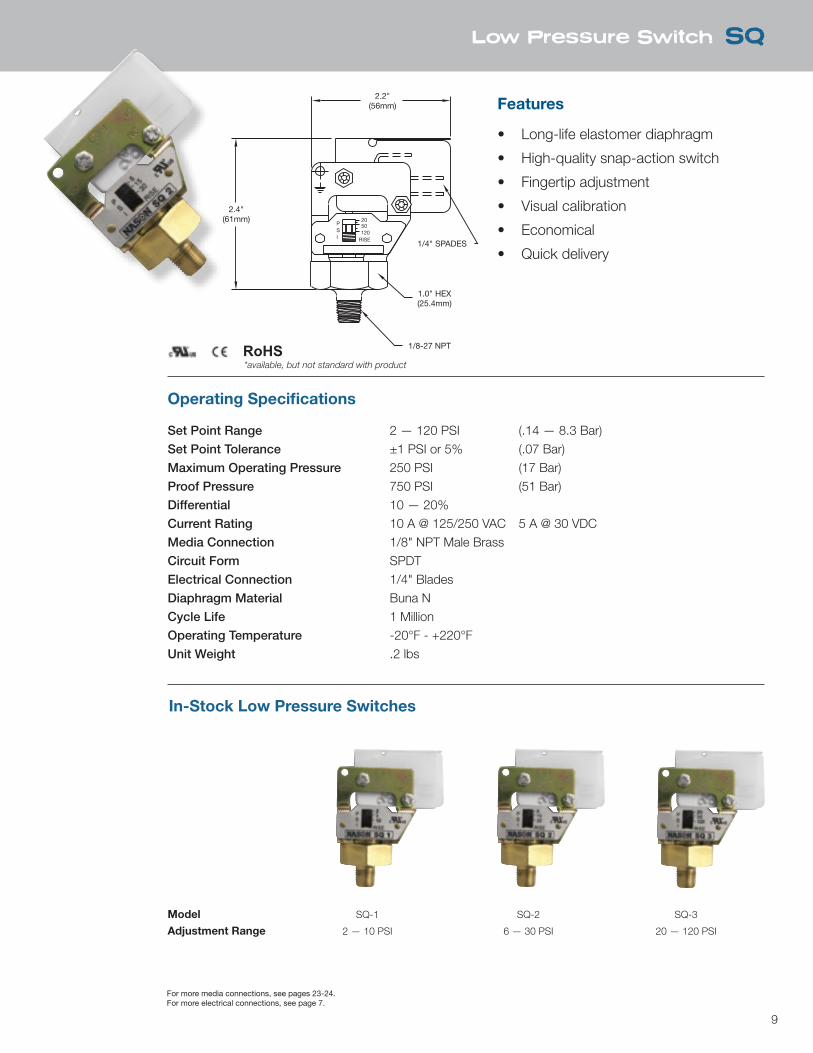
Low Pressure Switch SQ
Features
• Long-life elastomer diaphragm
• High-quality snap-action switch
• Fingertip adjustment
• Visual calibration
• Economical
• Quick delivery
Operating Specifications
Set Point Range 2 — 120 PSI (.14 — 8.3 Bar)Set Point Tolerance ±1 PSI or 5% (.07 Bar)Maximum Operating Pressure 250 PSI (17 Bar)Proof Pressure 750 PSI (51 Bar)Differential 10 — 20%Current Rating 10 A @ 125/250 VAC 5 A @ 30 VDCMedia Connection 1/8" NPT Male BrassCircuit Form SPDTElectrical Connection 1/4" BladesDiaphragm Material Buna NCycle Life 1 MillionOperating Temperature -20°F - +220°FUnit Weight .2 lbs
In-Stock Low Pressure Switches
Model SQ-1 SQ-2 SQ-3
Adjustment Range 2 — 10 PSI 6 — 30 PSI 20 — 120 PSI
For more media connections, see pages 23-24.For more electrical connections, see page 7.
RoHS*available, but not standard with product
10
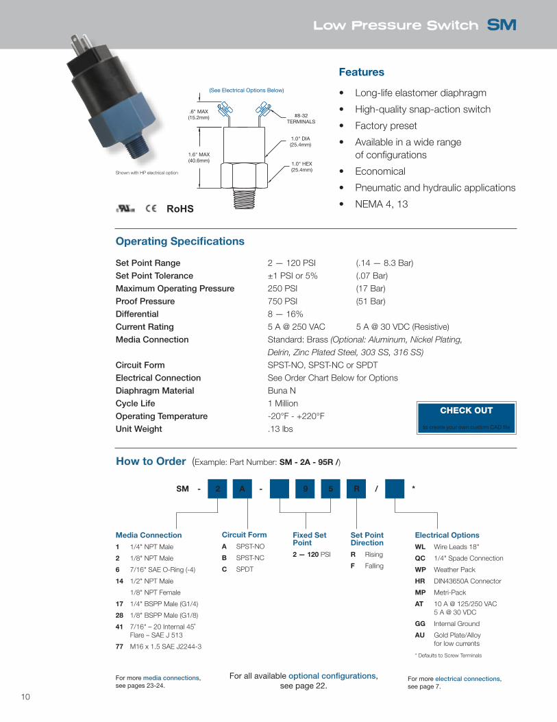
Low Pressure Switch SM
.6" MAX(15.2mm)
1.6" MAX(40.6mm)
1.0" HEX(25.4mm)
1.0" DIA(25.4mm)
#8-32TERMINALS
(See Electrical Options Below)
Features
• Long-life elastomer diaphragm
• High-quality snap-action switch
• Factory preset
• Available in a wide range of configurations
• Economical
• Pneumatic and hydraulic applications
• NEMA 4, 13
Operating Specifications
Set Point Range 2 — 120 PSI (.14 — 8.3 Bar)Set Point Tolerance ±1 PSI or 5% (.07 Bar)Maximum Operating Pressure 250 PSI (17 Bar)Proof Pressure 750 PSI (51 Bar)Differential 8 — 16%Current Rating 5 A @ 250 VAC 5 A @ 30 VDC (Resistive)Media Connection Standard: Brass (Optional: Aluminum, Nickel Plating,
Delrin, Zinc Plated Steel, 303 SS, 316 SS)
Circuit Form SPST-NO, SPST-NC or SPDTElectrical Connection See Order Chart Below for OptionsDiaphragm Material Buna NCycle Life 1 MillionOperating Temperature -20°F - +220°FUnit Weight .13 lbs
How to Order (Example: Part Number: SM - 2A - 95R /)
Media Connection
1 1/4" NPT Male
2 1/8" NPT Male
6 7/16" SAE O-Ring (-4)
14 1/2" NPT Male
1/8" NPT Female
17 1/4" BSPP Male (G1/4)
28 1/8" BSPP Male (G1/8)
41 7/16" – 20 Internal 45˚ Flare – SAE J 513
77 M16 x 1.5 SAE J2244-3
Circuit Form
A SPST-NO
B SPST-NC
C SPDT
Fixed Set Point
2 — 120 PSI
Set Point Direction
R Rising
F Falling
Electrical Options
WL Wire Leads 18"
QC 1/4" Spade Connection
WP Weather Pack
HR DIN43650A Connector
MP Metri-Pack
AT 10 A @ 125/250 VAC 5 A @ 30 VDC
GG Internal Ground
AU Gold Plate/Alloy for low currents
* Defaults to Screw Terminals
SM - 2 A - 9 5 R / *
Shown with HP electrical option
RoHS
For all available optional configurations, see page 22.
For more media connections, see pages 23-24.
For more electrical connections, see page 7.
CHECK OUTnasonptc.com/configureto create your own custom CAD file
11
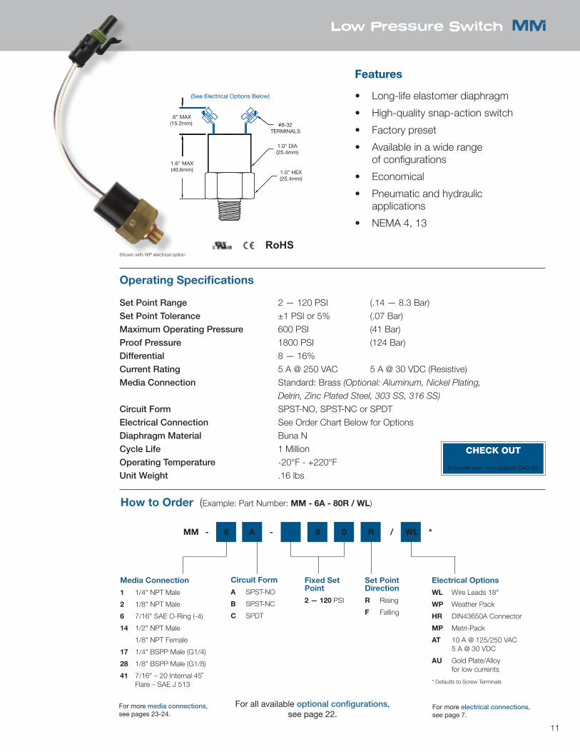
Low Pressure Switch MM
Features
• Long-life elastomer diaphragm
• High-quality snap-action switch
• Factory preset
• Available in a wide range of configurations
• Economical
• Pneumatic and hydraulic applications
• NEMA 4, 13
Operating Specifications
Set Point Range 2 — 120 PSI (.14 — 8.3 Bar)Set Point Tolerance ±1 PSI or 5% (.07 Bar)Maximum Operating Pressure 600 PSI (41 Bar)Proof Pressure 1800 PSI (124 Bar)Differential 8 — 16%Current Rating 5 A @ 250 VAC 5 A @ 30 VDC (Resistive)Media Connection Standard: Brass (Optional: Aluminum, Nickel Plating,
Delrin, Zinc Plated Steel, 303 SS, 316 SS)
Circuit Form SPST-NO, SPST-NC or SPDTElectrical Connection See Order Chart Below for OptionsDiaphragm Material Buna NCycle Life 1 MillionOperating Temperature -20°F - +220°FUnit Weight .16 lbs
How to Order (Example: Part Number: MM - 6A - 80R / WL)
Media Connection
1 1/4" NPT Male
2 1/8" NPT Male
6 7/16" SAE O-Ring (-4)
14 1/2" NPT Male
1/8" NPT Female
17 1/4" BSPP Male (G1/4)
28 1/8" BSPP Male (G1/8)
41 7/16" – 20 Internal 45˚ Flare – SAE J 513
Circuit Form
A SPST-NO
B SPST-NC
C SPDT
Fixed Set Point
2 — 120 PSI
Set Point Direction
R Rising
F Falling
Electrical Options
WL Wire Leads 18"
WP Weather Pack
HR DIN43650A Connector
MP Metri-Pack
AT 10 A @ 125/250 VAC 5 A @ 30 VDC
AU Gold Plate/Alloy for low currents
* Defaults to Screw Terminals
MM - 6 A - 8 0 R / WL *
1.6" MAX(40.6mm) 1.0" HEX
(25.4mm)
1.0" DIA(25.4mm)
.6” MAX(15.2mm) #8-32
TERMINALS
(See Electrical Options Below)
Shown with WP electrical option
RoHS
For all available optional configurations, see page 22.
For more media connections, see pages 23-24.
For more electrical connections, see page 7.
CHECK OUTnasonptc.com/configureto create your own custom CAD file

12
Low Pressure Switch LM
.6" MAX(15.2mm)
1.7" MAX(43.2mm)
1-1/8" HEX(28.6mm)
1.0" DIA(25.4mm)
#8-32TERMINALS
(See Electrical Options Below)
Features
• Long-life elastomer diaphragm
• High-quality snap-action switch
• Factory preset
• Available in a wide range of configurations
• Economical
• Pneumatic and hydraulic applications
• NEMA 4, 13
Operating Specifications
Set Point Range 10 — 300 PSI (.69 — 20 Bar)Set Point Tolerance ±1 PSI or 5% (.07 Bar)Maximum Operating Pressure 2000 PSI (137 Bar)Proof Pressure 6000 PSI (413 Bar)Differential 12 — 24%Current Rating 5 A @ 250 VAC 5 A @ 30 VDC (Resistive)Media Connection Standard: Brass (Optional: Nickel Plating, Delrin,
Zinc Plated Steel, 303 SS, 316 SS)
Circuit Form SPST-NO, SPST-NC or SPDTElectrical Connection See Order Chart Below for OptionsDiaphragm Material Buna NCycle Life 1 MillionOperating Temperature -20°F - +220°FUnit Weight .23 lbs
How to Order (Example: Part Number: LM - 6A - 250R / WL)
Media Connection
1 1/4" NPT Male
2 1/8" NPT Male
6 7/16" SAE O-Ring (-4)
12 M10 x 1 SAE J2244-3
49 M14 x 1.5 J2244/3
68 9/16" – 18 SAE O-Ring Face Seal (Female)
Circuit Form
A SPST-NO
B SPST-NC
C SPDT
Fixed Set Point
10 — 300 PSI
Set Point Direction
R Rising
F Falling
Electrical Options
WL Wire Leads 18"
WP Weather Pack
HR DIN43650A Connector
MP Metri-Pack
AT 10 A @ 125/250 VAC 5 A @ 30 VDC
AU Gold Plate/Alloy for low currents
* Defaults to Screw Terminals
LM - 6 A - 2 5 0 R / WL *
RoHS
For all available optional configurations, see page 22.
For more media connections, see pages 23-24.
For more electrical connections, see page 7.
Shown with unibody housing and EF electrical option
CHECK OUTnasonptc.com/configureto create your own custom CAD file
13
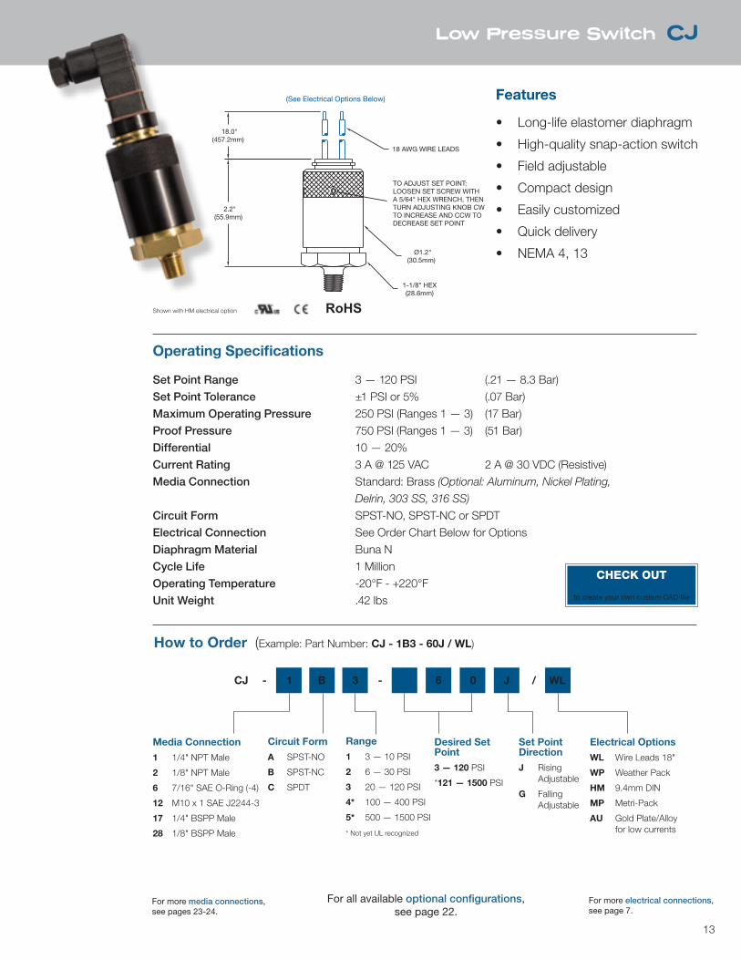
1-1/8" HEX(28.6mm)
Ø1.2"(30.5mm)
TO ADJUST SET POINT:LOOSEN SET SCREW WITHA 5/64" HEX WRENCH, THENTURN ADJUSTING KNOB CWTO INCREASE AND CCW TODECREASE SET POINT
18 AWG WIRE LEADS
18.0"(457.2mm)
2.2"(55.9mm)
(See Electrical Options Below)
Low Pressure Switch CJ
Features
• Long-life elastomer diaphragm
• High-quality snap-action switch
• Field adjustable
• Compact design
• Easily customized
• Quick delivery
• NEMA 4, 13
Operating Specifications
Set Point Range 3 — 120 PSI (.21 — 8.3 Bar)Set Point Tolerance ±1 PSI or 5% (.07 Bar)Maximum Operating Pressure 250 PSI (Ranges 1 — 3) (17 Bar)Proof Pressure 750 PSI (Ranges 1 — 3) (51 Bar) Differential 10 — 20%Current Rating 3 A @ 125 VAC 2 A @ 30 VDC (Resistive)Media Connection Standard: Brass (Optional: Aluminum, Nickel Plating,
Delrin, 303 SS, 316 SS)
Circuit Form SPST-NO, SPST-NC or SPDTElectrical Connection See Order Chart Below for OptionsDiaphragm Material Buna NCycle Life 1 MillionOperating Temperature -20°F - +220°FUnit Weight .42 lbs
How to Order (Example: Part Number: CJ - 1B3 - 60J / WL)
Media Connection
1 1/4" NPT Male
2 1/8" NPT Male
6 7/16" SAE O-Ring (-4)
12 M10 x 1 SAE J2244-3
17 1/4" BSPP Male
28 1/8" BSPP Male
Circuit Form
A SPST-NO
B SPST-NC
C SPDT
Desired Set Point
3 — 120 PSI
*121 — 1500 PSI
Set Point Direction
J Rising Adjustable
G Falling Adjustable
Electrical Options
WL Wire Leads 18"
WP Weather Pack
HM 9.4mm DIN
MP Metri-Pack
AU Gold Plate/Alloy for low currents
Range
1 3 — 10 PSI
2 6 — 30 PSI
3 20 — 120 PSI
4* 100 — 400 PSI
5* 500 — 1500 PSI
* Not yet UL recognized
CJ - 1 B 3 - 6 0 J / WL
Shown with HM electrical option RoHS
For all available optional configurations, see page 22.
For more media connections, see pages 23-24.
For more electrical connections, see page 7.
CHECK OUTnasonptc.com/configureto create your own custom CAD file
14
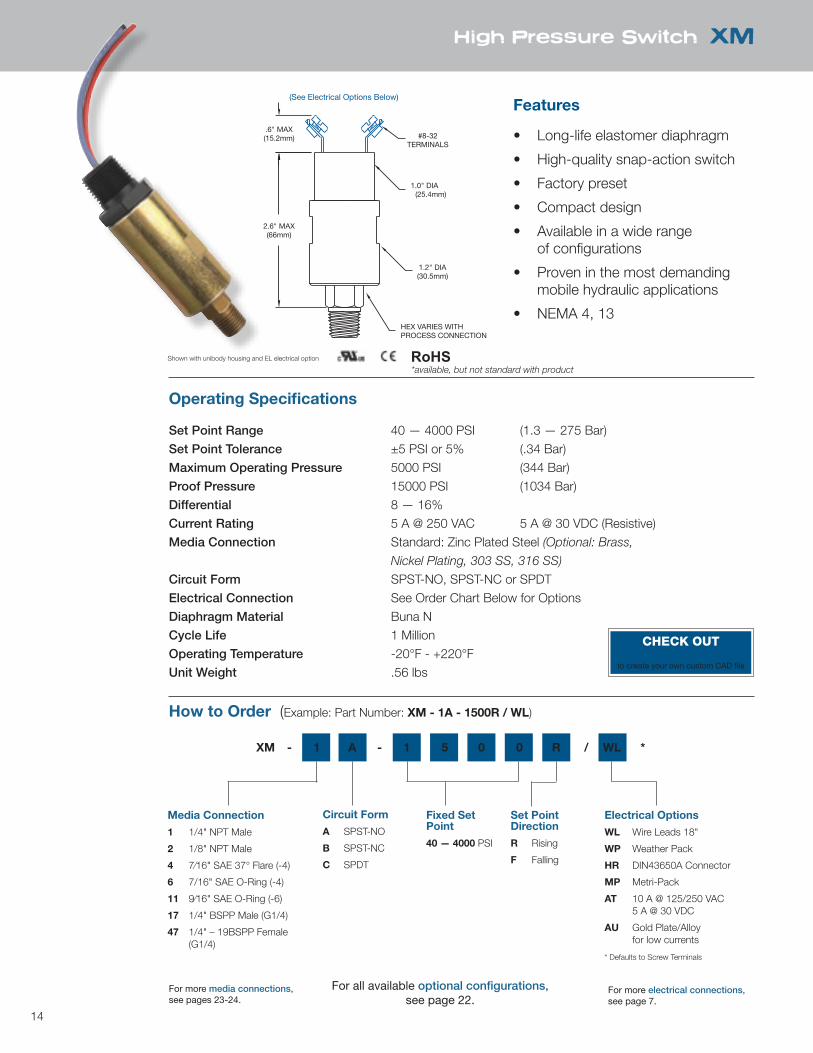
High Pressure Switch XM
.6" MAX(15.2mm)
2.6" MAX(66mm)
1.2" DIA(30.5mm)
1.0" DIA(25.4mm)
#8-32TERMINALS
HEX VARIES WITHPROCESS CONNECTION
(See Electrical Options Below)Features
• Long-life elastomer diaphragm
• High-quality snap-action switch
• Factory preset
• Compact design
• Available in a wide range of configurations
• Proven in the most demanding mobile hydraulic applications
• NEMA 4, 13
Operating Specifications
Set Point Range 40 — 4000 PSI (1.3 — 275 Bar)Set Point Tolerance ±5 PSI or 5% (.34 Bar)Maximum Operating Pressure 5000 PSI (344 Bar)Proof Pressure 15000 PSI (1034 Bar)Differential 8 — 16%Current Rating 5 A @ 250 VAC 5 A @ 30 VDC (Resistive)Media Connection Standard: Zinc Plated Steel (Optional: Brass,
Nickel Plating, 303 SS, 316 SS)
Circuit Form SPST-NO, SPST-NC or SPDTElectrical Connection See Order Chart Below for OptionsDiaphragm Material Buna NCycle Life 1 MillionOperating Temperature -20°F - +220°FUnit Weight .56 lbs
How to Order (Example: Part Number: XM - 1A - 1500R / WL)
Media Connection
1 1/4" NPT Male
2 1/8" NPT Male
4 7⁄16" SAE 37° Flare (-4)
6 7/16" SAE O-Ring (-4)
11 9⁄16" SAE O-Ring (-6)
17 1/4" BSPP Male (G1/4)
47 1/4" – 19BSPP Female (G1/4)
Circuit Form
A SPST-NO
B SPST-NC
C SPDT
Fixed Set Point
40 — 4000 PSI
Set Point Direction
R Rising
F Falling
Electrical Options
WL Wire Leads 18"
WP Weather Pack
HR DIN43650A Connector
MP Metri-Pack
AT 10 A @ 125/250 VAC 5 A @ 30 VDC
AU Gold Plate/Alloy for low currents
* Defaults to Screw Terminals
XM - 1 A - 1 5 0 0 R / WL *
RoHSShown with unibody housing and EL electrical option
For all available optional configurations, see page 22.
For more media connections, see pages 23-24.
For more electrical connections, see page 7.
CHECK OUTnasonptc.com/configureto create your own custom CAD file
*available, but not standard with product
15
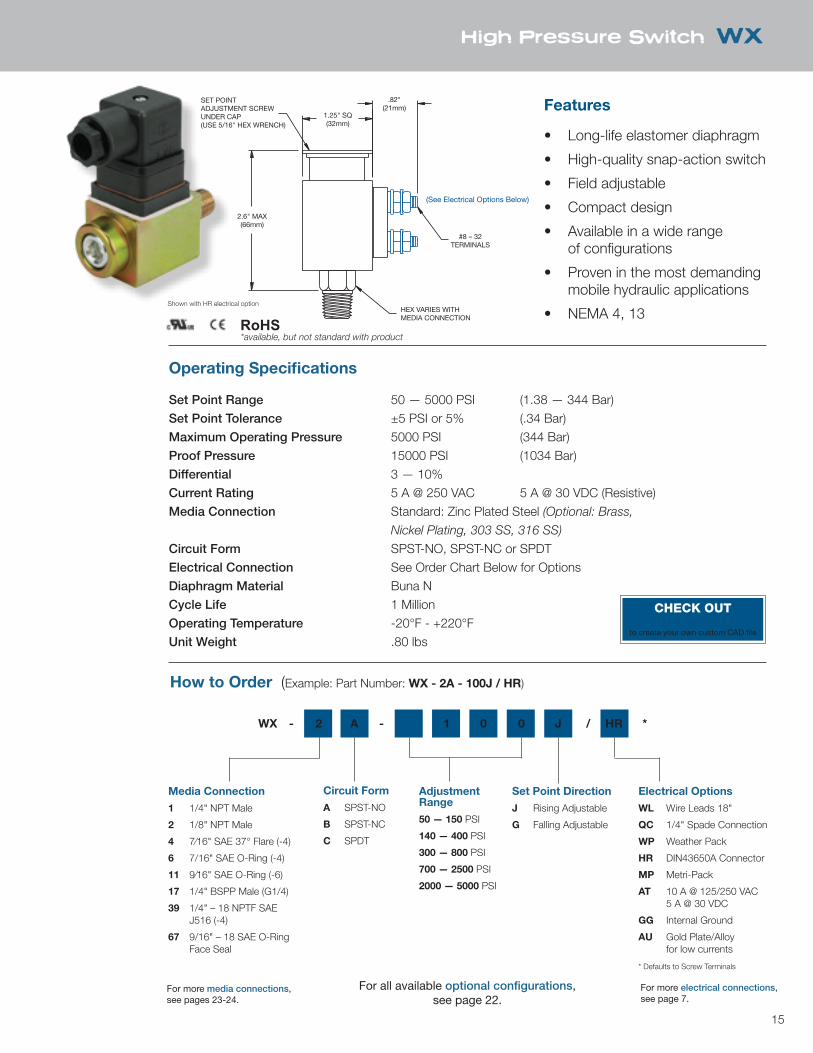
HEX VARIES WITHMEDIA CONNECTION
SET POINTADJUSTMENT SCREWUNDER CAP(USE 5/16" HEX WRENCH)
2.6" MAX(66mm)
1.25" SQ(32mm)
.82"(21mm)
#8 – 32TERMINALS
(See Electrical Options Below)
High Pressure Switch WX
Features
• Long-life elastomer diaphragm
• High-quality snap-action switch
• Field adjustable
• Compact design
• Available in a wide range of configurations
• Proven in the most demanding mobile hydraulic applications
• NEMA 4, 13
Operating Specifications
Set Point Range 50 — 5000 PSI (1.38 — 344 Bar)Set Point Tolerance ±5 PSI or 5% (.34 Bar)Maximum Operating Pressure 5000 PSI (344 Bar)Proof Pressure 15000 PSI (1034 Bar)Differential 3 — 10%Current Rating 5 A @ 250 VAC 5 A @ 30 VDC (Resistive)Media Connection Standard: Zinc Plated Steel (Optional: Brass,
Nickel Plating, 303 SS, 316 SS)
Circuit Form SPST-NO, SPST-NC or SPDTElectrical Connection See Order Chart Below for OptionsDiaphragm Material Buna NCycle Life 1 MillionOperating Temperature -20°F - +220°FUnit Weight .80 lbs
How to Order (Example: Part Number: WX - 2A - 100J / HR)
Media Connection
1 1/4" NPT Male
2 1/8" NPT Male
4 7⁄16" SAE 37° Flare (-4)
6 7/16" SAE O-Ring (-4)
11 9⁄16" SAE O-Ring (-6)
17 1/4" BSPP Male (G1/4)
39 1/4" – 18 NPTF SAE J516 (-4)
67 9/16" – 18 SAE O-Ring Face Seal
Circuit Form
A SPST-NO
B SPST-NC
C SPDT
Adjustment Range
50 — 150 PSI
140 — 400 PSI
300 — 800 PSI
700 — 2500 PSI
2000 — 5000 PSI
Set Point Direction
J Rising Adjustable
G Falling Adjustable
Electrical Options
WL Wire Leads 18"
QC 1/4" Spade Connection
WP Weather Pack
HR DIN43650A Connector
MP Metri-Pack
AT 10 A @ 125/250 VAC 5 A @ 30 VDC
GG Internal Ground
AU Gold Plate/Alloy for low currents
* Defaults to Screw Terminals
WX - 2 A - 1 0 0 J / HR *
Shown with HR electrical option
RoHS
For all available optional configurations, see page 22.
For more media connections, see pages 23-24.
For more electrical connections, see page 7.
CHECK OUTnasonptc.com/configureto create your own custom CAD file
*available, but not standard with product
16
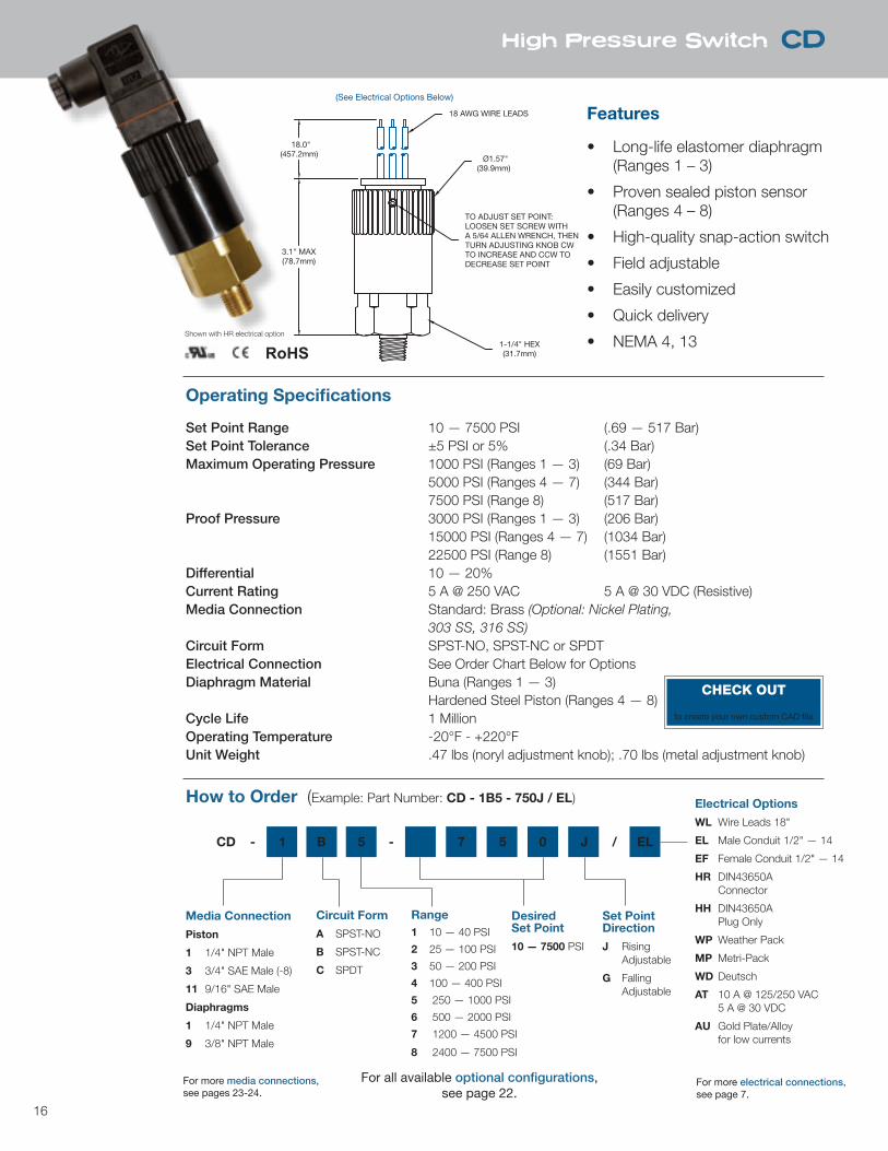
High Pressure Switch CD
Features
• Long-life elastomer diaphragm (Ranges 1 – 3)
• Proven sealed piston sensor (Ranges 4 – 8)
• High-quality snap-action switch
• Field adjustable
• Easily customized
• Quick delivery
• NEMA 4, 13
Operating Specifications
Set Point Range 10 — 7500 PSI (.69 — 517 Bar)Set Point Tolerance ±5 PSI or 5% (.34 Bar)Maximum Operating Pressure 1000 PSI (Ranges 1 — 3) (69 Bar) 5000 PSI (Ranges 4 — 7) (344 Bar) 7500 PSI (Range 8) (517 Bar)Proof Pressure 3000 PSI (Ranges 1 — 3) (206 Bar) 15000 PSI (Ranges 4 — 7) (1034 Bar) 22500 PSI (Range 8) (1551 Bar) Differential 10 — 20%Current Rating 5 A @ 250 VAC 5 A @ 30 VDC (Resistive)Media Connection Standard: Brass (Optional: Nickel Plating, 303 SS, 316 SS)Circuit Form SPST-NO, SPST-NC or SPDTElectrical Connection See Order Chart Below for OptionsDiaphragm Material Buna (Ranges 1 — 3) Hardened Steel Piston (Ranges 4 — 8)Cycle Life 1 MillionOperating Temperature -20°F - +220°FUnit Weight .47 lbs (noryl adjustment knob); .70 lbs (metal adjustment knob)
How to Order (Example: Part Number: CD - 1B5 - 750J / EL)
Media Connection
Piston
1 1/4" NPT Male
3 3/4" SAE Male (-8)
11 9/16" SAE Male
Diaphragms
1 1/4" NPT Male
9 3/8" NPT Male
Circuit Form
A SPST-NO
B SPST-NC
C SPDT
DesiredSet Point
10 — 7500 PSI
Set Point Direction
J Rising Adjustable
G Falling Adjustable
Electrical Options
WL Wire Leads 18"
EL Male Conduit 1/2" — 14
EF Female Conduit 1/2" — 14
HR DIN43650A Connector
HH DIN43650A Plug Only
WP Weather Pack
MP Metri-Pack
WD Deutsch
AT 10 A @ 125/250 VAC 5 A @ 30 VDC
AU Gold Plate/Alloy for low currents
Range1 10 — 40 PSI
2 25 — 100 PSI
3 50 — 200 PSI
4 100 — 400 PSI
5 250 — 1000 PSI
6 500 — 2000 PSI
7 1200 — 4500 PSI
8 2400 — 7500 PSI
CD - 1 B 5 - 7 5 0 J / EL
TO ADJUST SET POINT:LOOSEN SET SCREW WITHA 5/64 ALLEN WRENCH, THENTURN ADJUSTING KNOB CWTO INCREASE AND CCW TODECREASE SET POINT
18.0"(457.2mm)
3.1" MAX(78.7mm)
1-1/4" HEX(31.7mm)
Ø1.57"(39.9mm)
18 AWG WIRE LEADS
(See Electrical Options Below)
Shown with HR electrical option
RoHS
For all available optional configurations, see page 22.
For more media connections, see pages 23-24.
For more electrical connections, see page 7.
CHECK OUTnasonptc.com/configureto create your own custom CAD file
17
Electrical Options
WL Wire Leads 18"
EL Male Conduit 1/2" — 14
EF Female Conduit 1/2" — 14
HR DIN43650A Connector
HH DIN43650A Plug Only
WP Weather Pack
MP Metri-Pack
WD Deutsch
AT 10 A @ 125/250 VAC 5 A @ 30 VDC
AU Gold Plate/Alloy for low currents
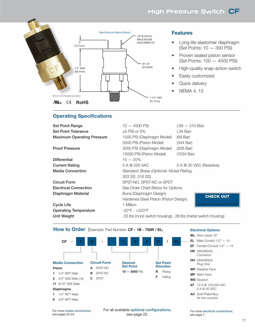
High Pressure Switch CF
Features
• Long-life elastomer diaphragm (Set Points: 10 — 300 PSI)
• Proven sealed piston sensor (Set Points: 100 — 4500 PSI)
• High-quality snap-action switch
• Easily customized
• Quick delivery
• NEMA 4, 13
Operating Specifications
Set Point Range 10 — 4500 PSI (.69 — 310 Bar)Set Point Tolerance ±5 PSI or 5% (.34 Bar)Maximum Operating Pressure 1000 PSI (Diaphragm Model) (69 Bar) 5000 PSI (Piston Model) (344 Bar)Proof Pressure 3000 PSI (Diaphragm Model) (206 Bar) 15000 PSI (Piston Model) (1034 Bar) Differential 10 — 20%Current Rating 5 A @ 250 VAC 5 A @ 30 VDC (Resistive)Media Connection Standard: Brass (Optional: Nickel Plating, 303 SS, 316 SS)Circuit Form SPST-NO, SPST-NC or SPDTElectrical Connection See Order Chart Below for OptionsDiaphragm Material Buna (Diaphragm Design) Hardened Steel Piston (Piston Design)Cycle Life 1 MillionOperating Temperature -20°F - +220°FUnit Weight .33 lbs (noryl switch housing); .38 lbs (metal switch housing)
How to Order (Example: Part Number: CF - 1B - 750R / EL)
Media Connection
Piston
1 1/4" NPT Male
3 3/4" SAE Male (-8)
11 9/16" SAE Male
Diaphragms
1 1/4" NPT Male
9 3/8" NPT Male
Circuit Form
A SPST-NO
B SPST-NC
C SPDT
DesiredSet Point
10 — 5000 PSI
Electrical Options
WL Wire Leads 18"
EL Male Conduit 1/2" — 14
EF Female Conduit 1/2" — 14
HR DIN43650A Connector
HH DIN43650A Plug Only
WP Weather Pack
MP Metri-Pack
WD Deutsch
AT 10 A @ 125/250 VAC 5 A @ 30 VDC
AU Gold Plate/Alloy for low currents
2.3" MAX(58.4mm)
Ø1.24"(31.5mm)
.5"(12.7mm)
1-1/4" HEX(31.7mm)
.25"(6.35mm)MALE BLADEDISCONNECTS
(See Electrical Options Below)
CF - 1 B - 7 5 0 R / EL
Set Point Direction
R Rising
F Falling
Shown with ES electrical option
For all available optional configurations, see page 22.
For more media connections, see pages 23-24.
For more electrical connections, see page 7.
RoHS
CHECK OUTnasonptc.com/configureto create your own custom CAD file
18 VA
CU
UM
SW
ITC
HES
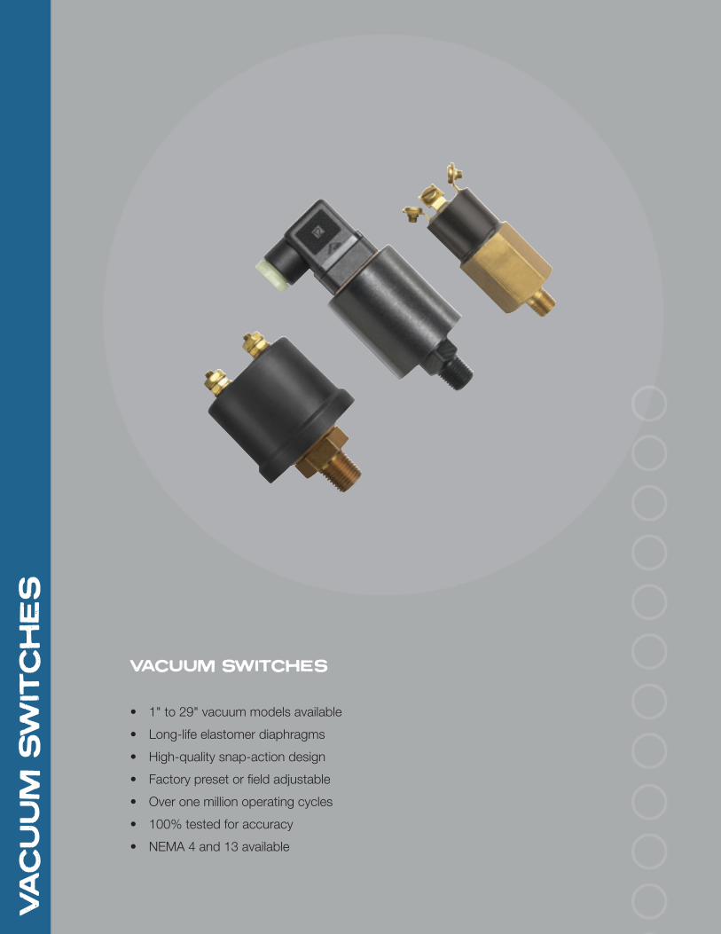
VACUUM SWITCHES
• 1" to 29" vacuum models available
• Long-life elastomer diaphragms
• High-quality snap-action design
• Factory preset or field adjustable
• Over one million operating cycles
• 100% tested for accuracy
• NEMA 4 and 13 available
19
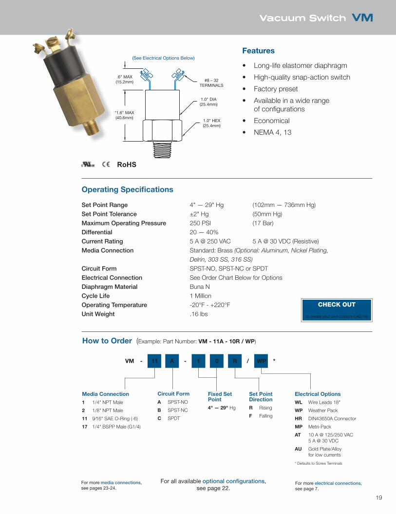
.6" MAX(15.2mm)
*1.6" MAX(40.6mm)
1.0" HEX(25.4mm)
1.0" DIA(25.4mm)
#8 – 32TERMINALS
*2.16" (54.9mm) FOR 1/8 PIPE CONNECTIONS
(See Electrical Options Below)
Vacuum Switch VM
Features
• Long-life elastomer diaphragm
• High-quality snap-action switch
• Factory preset
• Available in a wide range of configurations
• Economical
• NEMA 4, 13
Operating Specifications
Set Point Range 4" — 29" Hg (102mm — 736mm Hg)Set Point Tolerance ±2" Hg (50mm Hg)Maximum Operating Pressure 250 PSI (17 Bar)Differential 20 — 40%Current Rating 5 A @ 250 VAC 5 A @ 30 VDC (Resistive)Media Connection Standard: Brass (Optional: Aluminum, Nickel Plating,
Delrin, 303 SS, 316 SS)
Circuit Form SPST-NO, SPST-NC or SPDTElectrical Connection See Order Chart Below for OptionsDiaphragm Material Buna NCycle Life 1 MillionOperating Temperature -20°F - +220°FUnit Weight .16 lbs
How to Order (Example: Part Number: VM - 11A - 10R / WP)
Media Connection
1 1/4" NPT Male
2 1/8" NPT Male
11 9⁄16" SAE O-Ring (-6)
17 1/4" BSPP Male (G1/4)
Circuit Form
A SPST-NO
B SPST-NC
C SPDT
Fixed Set Point
4" — 29" Hg
Set Point Direction
R Rising
F Falling
Electrical Options
WL Wire Leads 18"
WP Weather Pack
HR DIN43650A Connector
MP Metri-Pack
AT 10 A @ 125/250 VAC 5 A @ 30 VDC
AU Gold Plate/Alloy for low currents
* Defaults to Screw Terminals
VM - 11 A - 1 0 R / WP *
RoHS
For all available optional configurations, see page 22.
For more media connections, see pages 23-24.
For more electrical connections, see page 7.
CHECK OUTnasonptc.com/configureto create your own custom CAD file
20
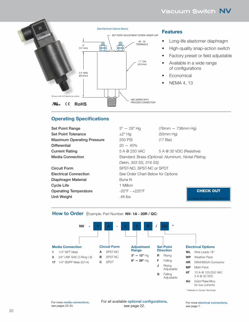
Vacuum Switch NV
#8 – 32TERMINALS
1.7" DIA(43.2mm)
2.5" MAX(63.5mm)
.5"(12.7mm)
SET POINT ADJUSTMENT SCREW UNDER CAP
HEX VARIES WITHPROCESS CONNECTION
(See Electrical Options Below)
Features
• Long-life elastomer diaphragm
• High-quality snap-action switch
• Factory preset or field adjustable
• Available in a wide range of configurations
• Economical
• NEMA 4, 13
Operating Specifications
Set Point Range 3" — 29" Hg (76mm — 736mm Hg)Set Point Tolerance ±2" Hg (50mm Hg)Maximum Operating Pressure 250 PSI (17 Bar)Differential 20 — 40%Current Rating 5 A @ 250 VAC 5 A @ 30 VDC (Resistive)Media Connection Standard: Brass (Optional: Aluminum, Nickel Plating,
Delrin, 303 SS, 316 SS)
Circuit Form SPST-NO, SPST-NC or SPDTElectrical Connection See Order Chart Below for OptionsDiaphragm Material Buna NCycle Life 1 MillionOperating Temperature -20°F - +220°FUnit Weight .48 lbs
How to Order (Example: Part Number: NV- 1A - 20R / QC)
Media Connection
1 1/4" NPT Male
3 3⁄4" UNF SAE O-Ring (-8)
17 1/4" BSPP Male (G1/4)
Circuit Form
A SPST-NO
B SPST-NC
C SPDT
Adjustment Range
3" — 12" Hg
8" — 29" Hg
Set Point Direction
R Rising
F Falling
J Rising Adjustable
G Falling Adjustable
Electrical Options
WL Wire Leads 18"
WP Weather Pack
HR DIN43650A Connector
MP Metri-Pack
AT 10 A @ 125/250 VAC 5 A @ 30 VDC
AU Gold Plate/Alloy for low currents
* Defaults to Screw Terminals
NV - 1 A - 2 0 R / QC *
Shown with HR electrical option
RoHS
For all available optional configurations, see page 22.
For more media connections, see pages 23-24.
For more electrical connections, see page 7.
CHECK OUTnasonptc.com/configureto create your own custom CAD file
21
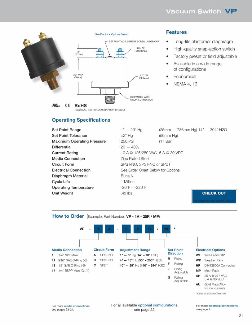
Vacuum Switch VP
SET POINT ADJUSTMENT SCREW UNDER CAP
HEX VARIES WITHMEDIA CONNECTION
.5"(12.7mm)
2.2" MAX(56mm)
2.0" DIA(50.8mm)
#8 – 32TERMINALS
(See Electrical Options Below) Features
• Long-life elastomer diaphragm
• High-quality snap-action switch
• Factory preset or field adjustable
• Available in a wide range of configurations
• Economical
• NEMA 4, 13
Operating Specifications
Set Point Range 1" — 29" Hg (25mm — 736mm Hg) 14" — 394" H2OSet Point Tolerance ±2" Hg (50mm Hg)Maximum Operating Pressure 250 PSI (17 Bar)Differential 20 — 40%Current Rating 10 A @ 125/250 VAC 5 A @ 30 VDCMedia Connection Zinc Plated SteelCircuit Form SPST-NO, SPST-NC or SPDTElectrical Connection See Order Chart Below for OptionsDiaphragm Material Buna NCycle Life 1 MillionOperating Temperature -20°F - +220°FUnit Weight .43 lbs
How to Order (Example: Part Number: VP - 1A - 25R / MP)
Media Connection
1 1/4" NPT Male
11 9⁄16" SAE O-Ring (-6)
13 1⁄2" SAE O-Ring (-5)
17 1/4" BSPP Male (G1/4)
Circuit Form
A SPST-NO
B SPST-NC
C SPDT
Adjustment Range
1" — 5" Hg (14" – 70" H2O)
4" — 15" Hg (55" – 200" H2O)
10" — 29" Hg (140" – 394" H2O)
Set Point Direction
R Rising
F Falling
J Rising Adjustable
G Falling Adjustable
Electrical Options
WL Wire Leads 18"
WP Weather Pack
HR DIN43650A Connector
MP Metri-Pack
AH 25 A @ 277 VAC 5 A @ 30 VDC
AU Gold Plate/Alloy for low currents
* Defaults to Screw Terminals
VP - 1 A - 2 5 R / MP *
RoHS
For all available optional configurations, see page 22.
For more media connections, see pages 23-24.
For more electrical connections, see page 7.
CHECK OUTnasonptc.com/configureto create your own custom CAD file
*available, but not standard with product
22
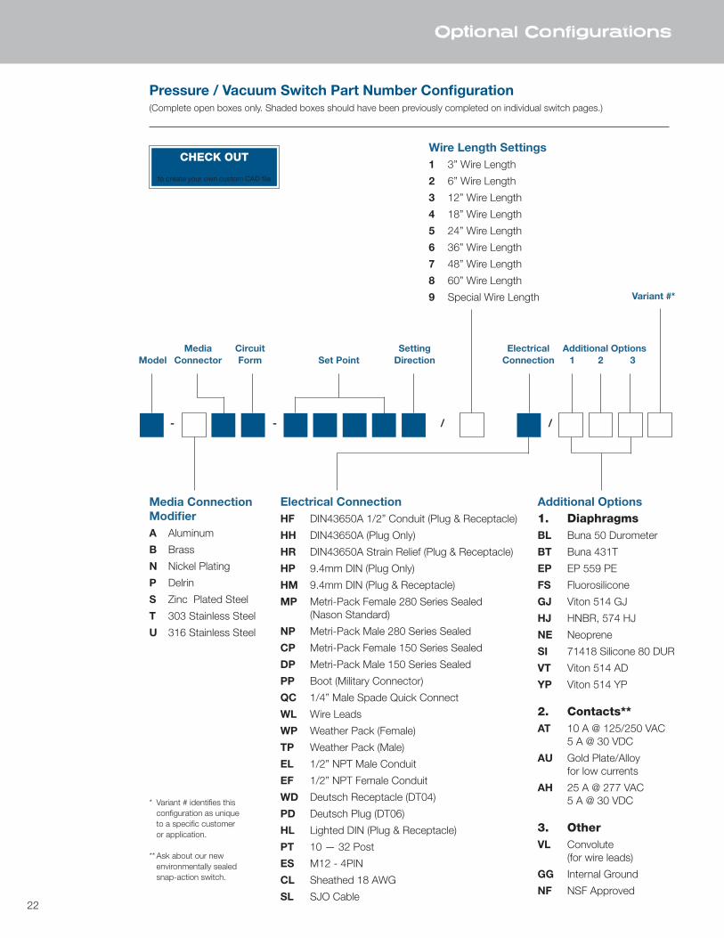
Optional Configurations
Pressure / Vacuum Switch Part Number Configuration(Complete open boxes only. Shaded boxes should have been previously completed on individual switch pages.)
- - / /
Wire Length Settings1 3” Wire Length
2 6” Wire Length
3 12” Wire Length
4 18” Wire Length
5 24” Wire Length
6 36” Wire Length
7 48” Wire Length
8 60” Wire Length
9 Special Wire Length
Media Connection ModifierA Aluminum
B Brass
N Nickel Plating
P Delrin
S Zinc Plated Steel
T 303 Stainless Steel
U 316 Stainless Steel
Electrical ConnectionHF DIN43650A 1/2” Conduit (Plug & Receptacle)
HH DIN43650A (Plug Only)
HR DIN43650A Strain Relief (Plug & Receptacle)
HP 9.4mm DIN (Plug Only)
HM 9.4mm DIN (Plug & Receptacle)
MP Metri-Pack Female 280 Series Sealed (Nason Standard)
NP Metri-Pack Male 280 Series Sealed
CP Metri-Pack Female 150 Series Sealed
DP Metri-Pack Male 150 Series Sealed
PP Boot (Military Connector)
QC 1/4” Male Spade Quick Connect
WL Wire Leads
WP Weather Pack (Female)
TP Weather Pack (Male)
EL 1/2” NPT Male Conduit
EF 1/2” NPT Female Conduit
WD Deutsch Receptacle (DT04)
PD Deutsch Plug (DT06)
HL Lighted DIN (Plug & Receptacle)
PT 10 — 32 Post
ES M12 - 4PIN
CL Sheathed 18 AWG
SL SJO Cable
Additional Options1. DiaphragmsBL Buna 50 Durometer
BT Buna 431T
EP EP 559 PE
FS Fluorosilicone
GJ Viton 514 GJ
HJ HNBR, 574 HJ
NE Neoprene
SI 71418 Silicone 80 DUR
VT Viton 514 AD
YP Viton 514 YP
2. Contacts**AT 10 A @ 125/250 VAC 5 A @ 30 VDC
AU Gold Plate/Alloy for low currents
AH 25 A @ 277 VAC 5 A @ 30 VDC
3. OtherVL Convolute (for wire leads)
GG Internal Ground
NF NSF Approved
Media Circuit Setting Electrical Additional OptionsModel Connector Form Set Point Direction Connection 1 2 3
Variant #*
* Variant # identifies this configuration as unique to a specific customer or application.
** Ask about our new environmentally sealed snap-action switch.
CHECK OUTnasonptc.com/configureto create your own custom CAD file
23
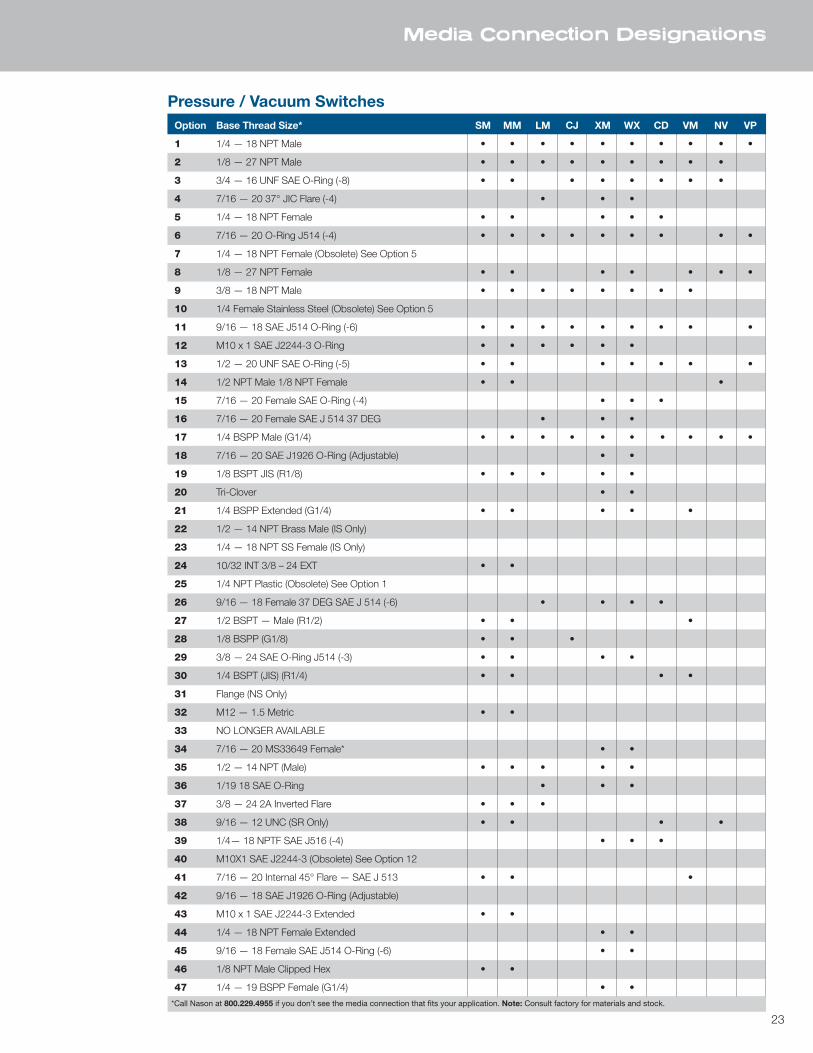
Option Base Thread Size* SM MM LM CJ XM WX CD VM NV VP
1 1/4 — 18 NPT Male • • • • • • • • • •
2 1/8 — 27 NPT Male • • • • • • • • •
3 3/4 — 16 UNF SAE O-Ring (-8) • • • • • • • •
4 7/16 — 20 37° JIC Flare (-4) • • •
5 1/4 — 18 NPT Female • • • • •
6 7/16 — 20 O-Ring J514 (-4) • • • • • • • • •
7 1/4 — 18 NPT Female (Obsolete) See Option 5
8 1/8 — 27 NPT Female • • • • • • •
9 3/8 — 18 NPT Male • • • • • • • •
10 1/4 Female Stainless Steel (Obsolete) See Option 5
11 9/16 — 18 SAE J514 O-Ring (-6) • • • • • • • • •
12 M10 x 1 SAE J2244-3 O-Ring • • • • • •
13 1/2 — 20 UNF SAE O-Ring (-5) • • • • • • •
14 1/2 NPT Male 1/8 NPT Female • • •
15 7/16 — 20 Female SAE O-Ring (-4) • • •
16 7/16 — 20 Female SAE J 514 37 DEG • • •
17 1/4 BSPP Male (G1/4) • • • • • • • • • •
18 7/16 — 20 SAE J1926 O-Ring (Adjustable) • •
19 1/8 BSPT JIS (R1/8) • • • • •
20 Tri-Clover • •
21 1/4 BSPP Extended (G1/4) • • • • •
22 1/2 — 14 NPT Brass Male (IS Only)
23 1/4 — 18 NPT SS Female (IS Only)
24 10/32 INT 3/8 – 24 EXT • •
25 1/4 NPT Plastic (Obsolete) See Option 1
26 9/16 — 18 Female 37 DEG SAE J 514 (-6) • • • •
27 1/2 BSPT — Male (R1/2) • • •
28 1/8 BSPP (G1/8) • • •
29 3/8 — 24 SAE O-Ring J514 (-3) • • • •
30 1/4 BSPT (JIS) (R1/4) • • • •
31 Flange (NS Only)
32 M12 — 1.5 Metric • •
33 NO LONGER AVAILABLE
34 7/16 — 20 MS33649 Female* • •
35 1/2 — 14 NPT (Male) • • • • •
36 1/19 18 SAE O-Ring • • •
37 3/8 — 24 2A Inverted Flare • • •
38 9/16 — 12 UNC (SR Only) • • • •
39 1/4— 18 NPTF SAE J516 (-4) • • •
40 M10X1 SAE J2244-3 (Obsolete) See Option 12
41 7/16 — 20 Internal 45° Flare — SAE J 513 • • •
42 9/16 — 18 SAE J1926 O-Ring (Adjustable)
43 M10 x 1 SAE J2244-3 Extended • •
44 1/4 — 18 NPT Female Extended • •
45 9/16 — 18 Female SAE J514 O-Ring (-6) • •
46 1/8 NPT Male Clipped Hex • •
47 1/4 — 19 BSPP Female (G1/4) • •
Media Connection Designations
*Call Nason at 800.229.4955 if you don’t see the media connection that fits your application. Note: Consult factory for materials and stock.
Pressure / Vacuum Switches
24
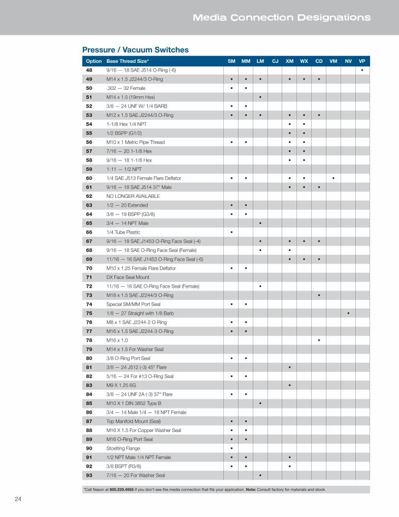
Media Connection Designations
Option Base Thread Size* SM MM LM CJ XM WX CD VM NV VP
48 9/16 — 18 SAE J514 O-Ring (-6) •
49 M14 x 1.5 J2244/3 O-Ring • • • • • •
50 .302 — 32 Female • •
51 M14 x 1.5 (19mm Hex) •
52 3/8 — 24 UNF W/ 1/4 BARB • •
53 M12 x 1.5 SAE J2244/3 O-Ring • • • • • •
54 1-1/8 Hex 1/4 NPT • •
55 1/2 BSPP (G1/2) • •
56 M10 x 1 Metric Pipe Thread • • • •
57 7/16 — 20 1-1/8 Hex • •
58 9/16 — 18 1-1/8 Hex • •
59 1-11 — 1/2 NPT
60 1/4 SAE J513 Female Flare Deflator • • • • •
61 9/16 — 18 SAE J514 37° Male • • •
62 NO LONGER AVAILABLE
63 1/2 — 20 Extended • •
64 3/8 — 19 BSPP (G3/8) • •
65 3/4 — 14 NPT Male •
66 1/4 Tube Plastic •
67 9/16 — 18 SAE J1453 O-Ring Face Seal (-4) • • • •
68 9/16 — 18 SAE O-Ring Face Seal (Female) • •
69 11/16 — 16 SAE J1453 O-Ring Face Seal (-6) • • •
70 M10 x 1.25 Female Flare Deflator • •
71 DX Face Seal Mount
72 11/16 — 16 SAE O-Ring Face Seal (Female) •
73 M18 x 1.5 SAE J2244/3 O-Ring •
74 Special SM/MM Port Seal • •
75 1/8 — 27 Straight with 1/8 Barb •
76 M8 x 1 SAE J2244-2 O-Ring • •
77 M16 x 1.5 SAE J2244-3 O-Ring • •
78 M16 x 1.0 •
79 M14 x 1.5 For Washer Seal
80 3/8 O-Ring Port Seal • •
81 3/8 — 24 J512 (-3) 45° Flare •
82 5/16 — 24 For #13 O-Ring Seal • •
83 M9 X 1.25 6G •
84 3/8 — 24 UNF 2A (-3) 37° Flare • •
85 M10 X 1 DIN 3852 Type B •
86 3/4 — 14 Male 1/4 — 18 NPT Female
87 Top Manifold Mount (Seal) • •
88 M16 X 1.5 For Copper Washer Seal • •
89 M16 O-Ring Port Seal • •
90 Stoelting Flange •
91 1/2 NPT Male 1/4 NPT Female • • •
92 3/8 BSPT (R3/8) • • •
93 7/16 — 20 For Washer Seal •
*Call Nason at 800.229.4955 if you don’t see the media connection that fits your application. Note: Consult factory for materials and stock.
Pressure / Vacuum Switches
25
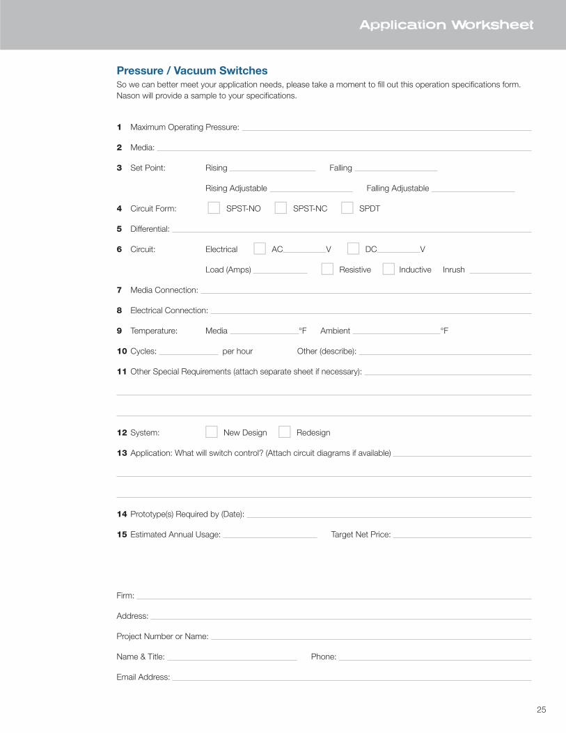
Application Worksheet
Pressure / Vacuum SwitchesSo we can better meet your application needs, please take a moment to fill out this operation specifications form.Nason will provide a sample to your specifications.
1 Maximum Operating Pressure:
2 Media:
3 Set Point: Rising Falling
Rising Adjustable Falling Adjustable
4 Circuit Form: c SPST-NO c SPST-NC c SPDT
5 Differential:
6 Circuit: Electrical c AC V c DC V
Load (Amps) c Resistive c Inductive Inrush
7 Media Connection:
8 Electrical Connection:
9 Temperature: Media °F Ambient °F
10 Cycles: per hour Other (describe):
11 Other Special Requirements (attach separate sheet if necessary):
12 System: c New Design c Redesign
13 Application: What will switch control? (Attach circuit diagrams if available)
14 Prototype(s) Required by (Date):
15 Estimated Annual Usage: Target Net Price:
Firm:
Address:
Project Number or Name:
Name & Title: Phone:
Email Address:
26 TE
MP
ERAT
URE
SW
ITC
HES
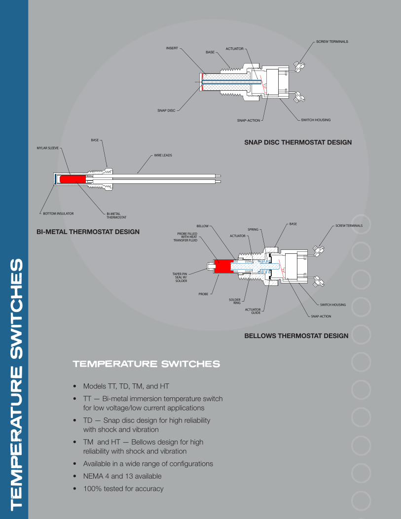
TEMPERATURE SWITCHES
• Models TT, TD, TM, and HT
• TT — Bi-metal immersion temperature switch for low voltage/low current applications
• TD — Snap disc design for high reliability with shock and vibration
• TM and HT — Bellows design for high reliability with shock and vibration
• Available in a wide range of configurations
• NEMA 4 and 13 available
• 100% tested for accuracy
BASE
SNAP DISC
INSERT ACTUATOR
SNAP-ACTION SWITCH HOUSING
SCREW TERMINALS
BELLOWSPRING
ACTUATORGUIDE
PROBE
TAPER PINSEAL W/SOLDER
SOLDERRING
BASE
ACTUATOR
SNAP-ACTION
SWITCH HOUSING
SCREW TERMINALS
PROBE FILLED WITH HEAT
TRANSFER FLUID
BASE
BOTTOM INSULATOR
MYLAR SLEEVE
WIRE LEADS
BI-METALTHERMOSTAT
SNAP DISC THERMOSTAT DESIGN
BI-METAL THERMOSTAT DESIGN
BELLOWS THERMOSTAT DESIGN
27
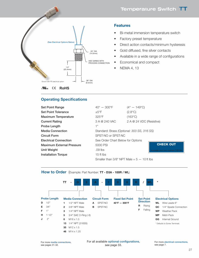
Temperature Switch TT
1.0"(25.4mm)
.55" DIA(14.0mm)
HEX VARIES WITHPROCESS CONNECTION
.38" DIA(9.5mm)
(See Electrical Options Below)
Features
• Bi-metal immersion temperature switch
• Factory preset temperature
• Direct action contacts/minimum hysteresis
• Gold diffused, fine silver contacts
• Available in a wide range of configurations
• Economical and compact
• NEMA 4, 13
Operating Specifications
Set Point Range 40° — 300°F (4° — 149°C)
Set Point Tolerance ±5°F (2.8°C)
Maximum Temperature 325°F (163°C)
Current Rating 3 A @ 240 VAC 2 A @ 24 VDC (Resistive)
Probe Length 1"
Media Connection Standard: Brass (Optional: 303 SS, 316 SS)
Circuit Form SPST-NO or SPST-NC
Electrical Connection See Order Chart Below for Options
Maximum External Pressure 5000 PSI
Unit Weight .09 lbs
Installation Torque 15 ft lbs
Smaller than 3/8" NPT Male = 5 — 10 ft lbs
How to Order (Example: Part Number: TT - D3A - 100R / WL)
Media Connection
1 1/2" NPT Male
2 3/8" NPT Male
3 1/4" NPT Male
5 3/4" SAE O-Ring (-8)
6 M16 x 1.5
13 1/4" NPT (316SS)
35 M12 x 1.5
46 M14 x 1.25
Circuit Form
A SPST-NO
B SPST-NC
Fixed Set Point
40°F — 300°F
Set Point Direction
R Rising
F Falling
Electrical Options
WL Wire Leads 6"
QC 1/4" Spade Connection
WP Weather Pack
MP Metri-Pack
GG Internal Ground
* Defaults to Screw Terminals
Probe Length
D 1⁄2”
E 3⁄4”
F 1”
H 1-1⁄2”
J 2”
TT - D 3 A - 1 0 0 R / WL *
Shown with PD electrical option
RoHS
For all available optional configurations, see page 33.
For more media connections, see pages 31-32.
For more electrical connections, see page 7.
CHECK OUTnasonptc.com/configureto create your own custom CAD file
28
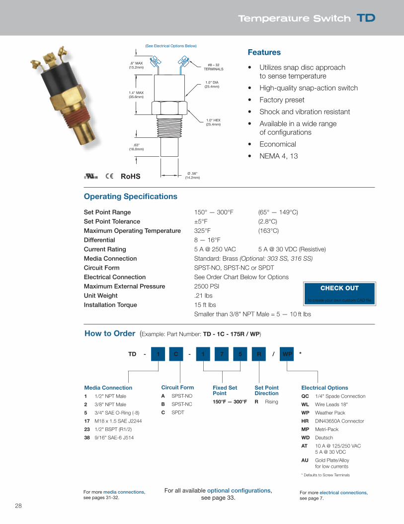
Temperature Switch TD
.6" MAX(15.2mm)
1.4" MAX(35.6mm)
.63"(16.0mm)
Ø .56"(14.2mm)
1.0" HEX(25.4mm)
1.0" DIA(25.4mm)
#8 – 32TERMINALS
(See Electrical Options Below)
Features
• Utilizes snap disc approach to sense temperature
• High-quality snap-action switch
• Factory preset
• Shock and vibration resistant
• Available in a wide range of configurations
• Economical
• NEMA 4, 13
Operating Specifications
Set Point Range 150° — 300°F (65° — 149°C)Set Point Tolerance ±5°F (2.8°C)Maximum Operating Temperature 325°F (163°C)Differential 8 — 16°FCurrent Rating 5 A @ 250 VAC 5 A @ 30 VDC (Resistive)Media Connection Standard: Brass (Optional: 303 SS, 316 SS)
Circuit Form SPST-NO, SPST-NC or SPDTElectrical Connection See Order Chart Below for OptionsMaximum External Pressure 2500 PSIUnit Weight .21 lbsInstallation Torque 15 ft lbs Smaller than 3/8" NPT Male = 5 — 10 ft lbs
How to Order (Example: Part Number: TD - 1C - 175R / WP)
Media Connection
1 1/2" NPT Male
2 3/8" NPT Male
5 3/4" SAE O-Ring (-8)
17 M18 x 1.5 SAE J2244
23 1/2" BSPT (R1/2)
38 9/16" SAE-6 J514
Circuit Form
A SPST-NO
B SPST-NC
C SPDT
Fixed Set Point
150°F — 300°F
Set Point Direction
R Rising
Electrical Options
QC 1/4" Spade Connection
WL Wire Leads 18"
WP Weather Pack
HR DIN43650A Connector
MP Metri-Pack
WD Deutsch
AT 10 A @ 125/250 VAC 5 A @ 30 VDC
AU Gold Plate/Alloy for low currents
* Defaults to Screw Terminals
TD - 1 C - 1 7 5 R / WP *
RoHS
For all available optional configurations, see page 33.
For more media connections, see pages 31-32.
For more electrical connections, see page 7.
CHECK OUTnasonptc.com/configureto create your own custom CAD file
29
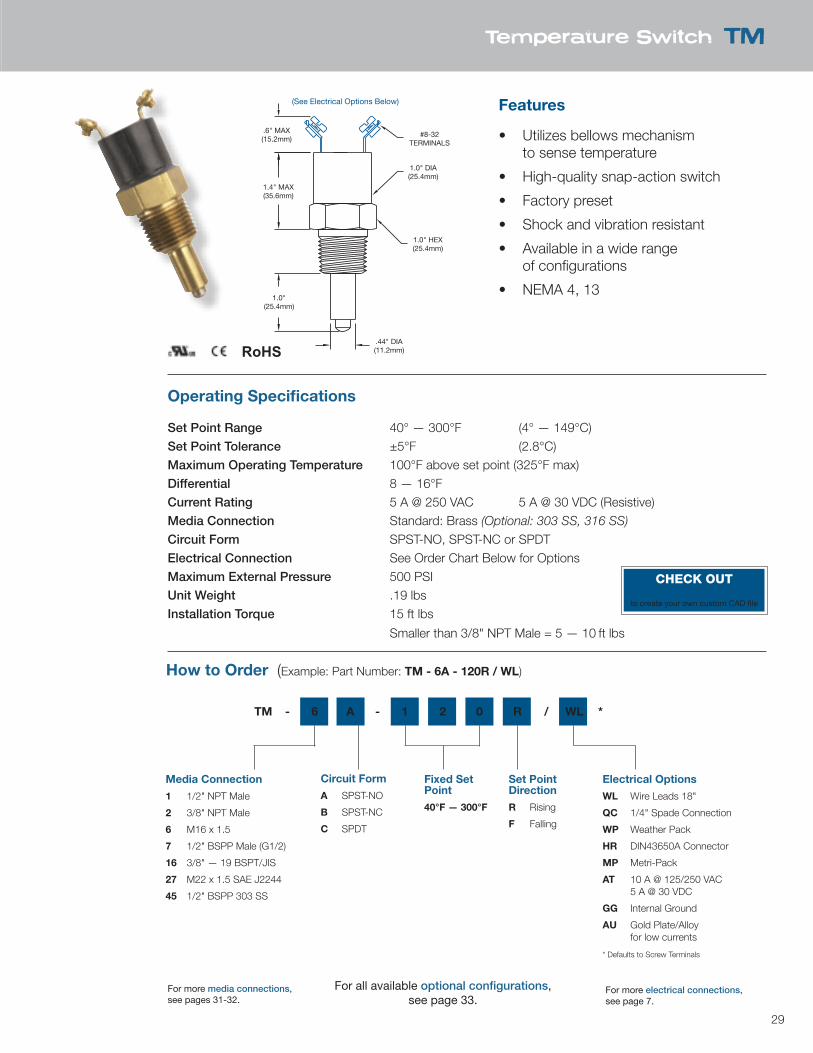
Temperature Switch TM
.6" MAX(15.2mm)
1.4" MAX(35.6mm)
1.0"(25.4mm)
.44" DIA(11.2mm)
1.0" HEX(25.4mm)
1.0" DIA(25.4mm)
#8-32TERMINALS
(See Electrical Options Below) Features
• Utilizes bellows mechanism to sense temperature
• High-quality snap-action switch
• Factory preset
• Shock and vibration resistant
• Available in a wide range of configurations
• NEMA 4, 13
Operating Specifications
Set Point Range 40° — 300°F (4° — 149°C)Set Point Tolerance ±5°F (2.8°C)Maximum Operating Temperature 100°F above set point (325°F max)Differential 8 — 16°FCurrent Rating 5 A @ 250 VAC 5 A @ 30 VDC (Resistive)Media Connection Standard: Brass (Optional: 303 SS, 316 SS)
Circuit Form SPST-NO, SPST-NC or SPDTElectrical Connection See Order Chart Below for OptionsMaximum External Pressure 500 PSIUnit Weight .19 lbsInstallation Torque 15 ft lbs
Smaller than 3/8" NPT Male = 5 — 10 ft lbs
How to Order (Example: Part Number: TM - 6A - 120R / WL)
Media Connection
1 1/2" NPT Male
2 3/8" NPT Male
6 M16 x 1.5
7 1/2" BSPP Male (G1/2)
16 3/8" — 19 BSPT/JIS
27 M22 x 1.5 SAE J2244
45 1/2" BSPP 303 SS
Circuit Form
A SPST-NO
B SPST-NC
C SPDT
Fixed Set Point
40°F — 300°F
Set Point Direction
R Rising
F Falling
Electrical Options
WL Wire Leads 18"
QC 1/4" Spade Connection
WP Weather Pack
HR DIN43650A Connector
MP Metri-Pack
AT 10 A @ 125/250 VAC 5 A @ 30 VDC
GG Internal Ground
AU Gold Plate/Alloy for low currents
* Defaults to Screw Terminals
TM - 6 A - 1 2 0 R / WL *
RoHS
For all available optional configurations, see page 33.
For more media connections, see pages 31-32.
For more electrical connections, see page 7.
CHECK OUTnasonptc.com/configureto create your own custom CAD file
30
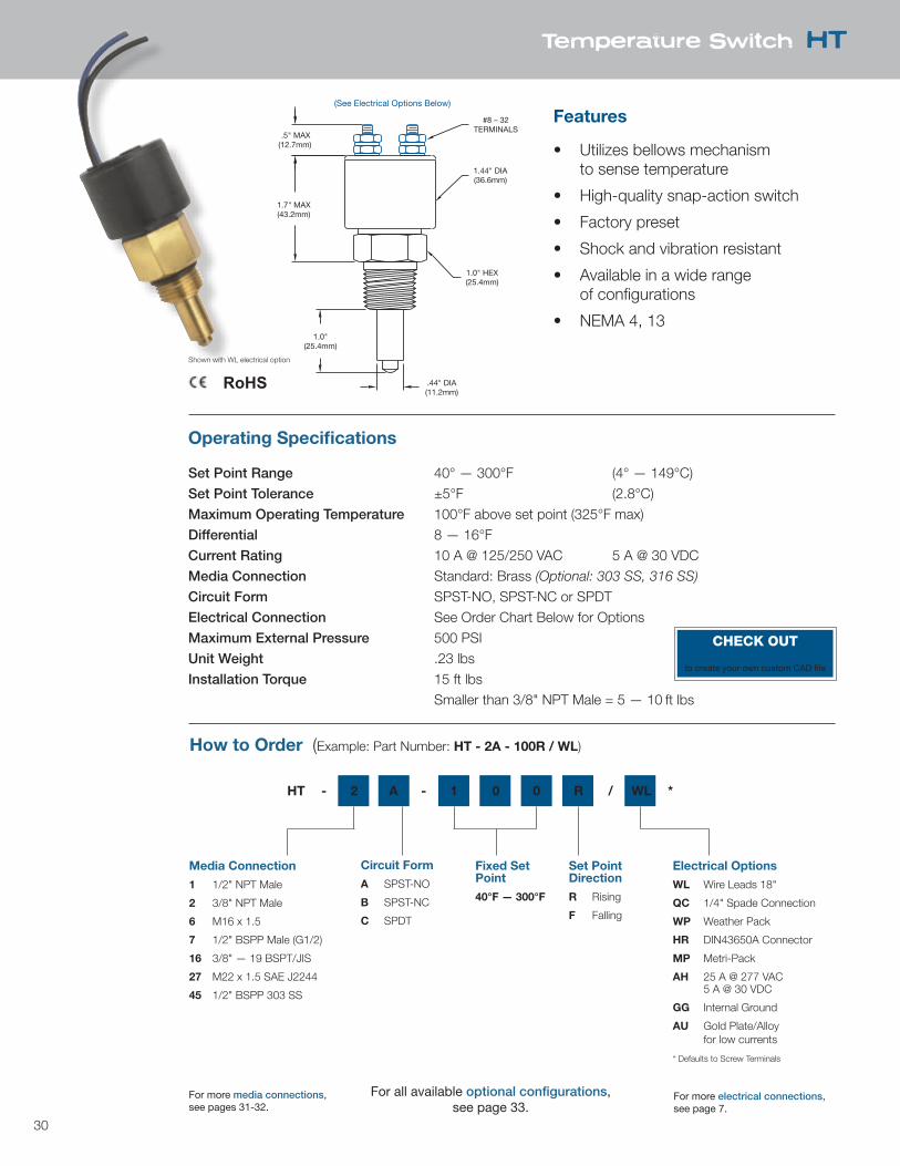
Temperature Switch HT
.5" MAX(12.7mm)
1.7" MAX(43.2mm)
1.0"(25.4mm)
.44" DIA(11.2mm)
1.0" HEX(25.4mm)
1.44" DIA(36.6mm)
#8 – 32TERMINALS
(See Electrical Options Below)
Features
• Utilizes bellows mechanism to sense temperature
• High-quality snap-action switch
• Factory preset
• Shock and vibration resistant
• Available in a wide range of configurations
• NEMA 4, 13
Operating Specifications
Set Point Range 40° — 300°F (4° — 149°C)Set Point Tolerance ±5°F (2.8°C)Maximum Operating Temperature 100°F above set point (325°F max)Differential 8 — 16°FCurrent Rating 10 A @ 125/250 VAC 5 A @ 30 VDCMedia Connection Standard: Brass (Optional: 303 SS, 316 SS)
Circuit Form SPST-NO, SPST-NC or SPDTElectrical Connection See Order Chart Below for OptionsMaximum External Pressure 500 PSIUnit Weight .23 lbsInstallation Torque 15 ft lbs Smaller than 3/8" NPT Male = 5 — 10 ft lbs
How to Order (Example: Part Number: HT - 2A - 100R / WL)
Media Connection
1 1/2" NPT Male
2 3/8" NPT Male
6 M16 x 1.5
7 1/2" BSPP Male (G1/2)
16 3/8" — 19 BSPT/JIS
27 M22 x 1.5 SAE J2244
45 1/2" BSPP 303 SS
Circuit Form
A SPST-NO
B SPST-NC
C SPDT
Fixed Set Point
40°F — 300°F
Set Point Direction
R Rising
F Falling
Electrical Options
WL Wire Leads 18"
QC 1/4" Spade Connection
WP Weather Pack
HR DIN43650A Connector
MP Metri-Pack
AH 25 A @ 277 VAC 5 A @ 30 VDC
GG Internal Ground
AU Gold Plate/Alloy for low currents
* Defaults to Screw Terminals
HT - 2 A - 1 0 0 R / WL *
Shown with WL electrical option
RoHS
For all available optional configurations, see page 33.
For more media connections, see pages 31-32.
For more electrical connections, see page 7.
CHECK OUTnasonptc.com/configureto create your own custom CAD file
31
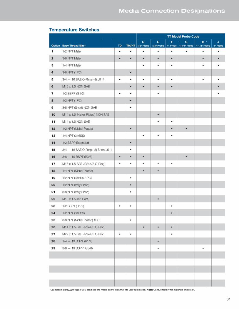
Media Connection Designations
TT Model Probe Code
D E F G H JOption Base Thread Size* TD TM/HT 1/2" Probe 3/4" Probe 1" Probe 1-1/4" Probe 1-1/2" Probe 2" Probe
1 1/2 NPT Male • • • • • • • •
2 3/8 NPT Male • • • • • • •
3 1/4 NPT Male • • • • •
4 3/8 NPT (1PC) •
5 3/4 — 16 SAE O-Ring (-8) J514 • • • • • • •
6 M16 x 1.5 NON SAE • • • • •
7 1/2 BSPP (G1/2) • • • •
8 1/2 NPT (1PC) •
9 3/8 NPT (Short) NON SAE •
10 M14 x 1.5 (Nickel Plated) NON SAE •
11 M14 x 1.5 NON SAE • •
12 1/2 NPT (Nickel Plated) • • •
13 1/4 NPT (316SS) • • •
14 1/2 BSPP Extended •
15 3/4 — 16 SAE O-Ring (-8) Short J514 •
16 3/8 — 19 BSPT (R3/8) • • • •
17 M18 x 1.5 SAE J2244/3 O-Ring • • • • •
18 1/4 NPT (Nickel Plated) • •
19 1/2 NPT (316SS-1PC) •
20 1/2 NPT (Very Short) •
21 3/8 NPT (Very Short) •
22 M16 x 1.5 45° Flare •
23 1/2 BSPT (R1/2) • • •
24 1/2 NPT (316SS) •
25 3/8 NPT (Nickel Plated) 1PC •
26 M14 x 1.5 SAE J2244/3 O-Ring • • •
27 M22 x 1.5 SAE J2244/3 O-Ring • • •
28 1/4 — 19 BSPT (R1/4) •
29 3/8 — 19 BSPP (G3/8) • •
Temperature Switches
*Call Nason at 800.229.4955 if you don’t see the media connection that fits your application. Note: Consult factory for materials and stock.

32
Media Connection Designations
TT Model Probe Code
D E F G H JOption Base Thread Size* TD TM/HT 1/2" Probe 3/4" Probe 1" Probe 1-1/4" Probe 1-1/2" Probe 2" Probe
Temperature Switches
30 3/8 NPT (316SS) • • •
31 3/4 — 16 UNF (304 SS) •
32 M16 x 1.5 (SAE) J2244/3
33 5/8 — 18 SAE J513 45° Flare • •
34 1/2 NPT (Short) Male •
35 M12 x 1.5 SAE J2244/3 • •
36 3/4 — 16 SAE O-Ring (Nickel Plated)
37 M14 x 1.5 Taper Thread
38 9/16 — 18 SAE J514 O-Ring (-6) • • • • • • •
39 M16 x 2.0 •
40 1/2 — 20 UNF SAE J514 O-Ring (-5) • •
41 3/8 — 24 SAE J514 O-Ring (-3) •
42 1/8 NPT Male • •
43 1/4 — 19 BSPP (G1/4) • •
44 M16 x 1.5 303 SS •
45 1/2 BSPP 303 SS (G1/2) • •
46 M14 x 1.25 •
47 M16 x 1.5 45° Flare • •
48 7/16 — 20 SAE J514 O-Ring (-4) • •
49 1 1/16 — 12 SAE J514 O-Ring (-12) • •
50 1/8 — 28 BSPT (R1/8) •
51 M20X 1.5 Taper
52 3/8 NPT 303 SS Male
53 M16 X 1.5 For Washer • • • • •
54 M10 X 1.5
55 1/8 — 28 BSPP (G 1/8) •
56 M12 x 1.5 For Washer •
57 3/8 — 19 BSPP Washer (G3/8) •
58 1/4 — 19 BSPP (G1/4) 316 SS •
59 7/8 — 14 SAE J514 O-Ring (-10) •
60 3/4 — 16 SAE J514 O-Ring (-8) •
61 M10 x 1.0 •
62 3/4 — 16 for Washer Seal •
*Call Nason at 800.229.4955 if you don’t see the media connection that fits your application. Note: Consult factory for materials and stock.
33
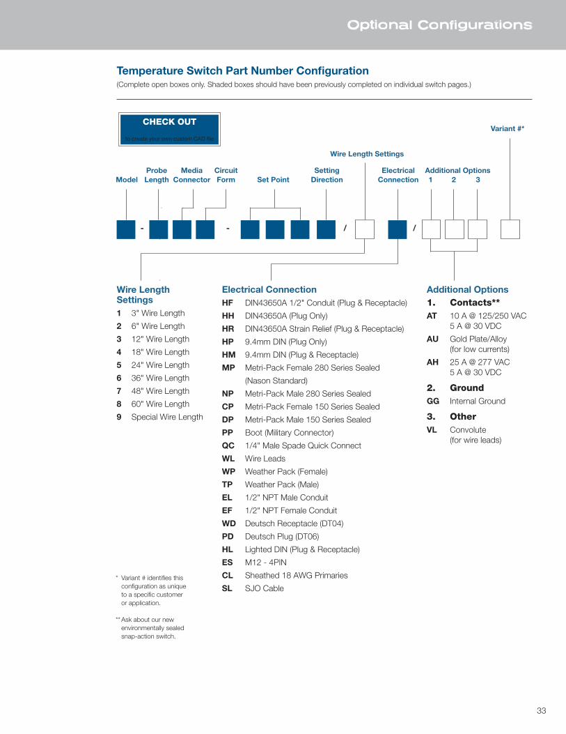
Optional Configurations
Temperature Switch Part Number Configuration(Complete open boxes only. Shaded boxes should have been previously completed on individual switch pages.)
- - / /
Wire LengthSettings1 3" Wire Length
2 6" Wire Length
3 12" Wire Length
4 18" Wire Length
5 24" Wire Length
6 36" Wire Length
7 48" Wire Length
8 60" Wire Length
9 Special Wire Length
Electrical ConnectionHF DIN43650A 1/2" Conduit (Plug & Receptacle)
HH DIN43650A (Plug Only)
HR DIN43650A Strain Relief (Plug & Receptacle)
HP 9.4mm DIN (Plug Only)
HM 9.4mm DIN (Plug & Receptacle)
MP Metri-Pack Female 280 Series Sealed
(Nason Standard)
NP Metri-Pack Male 280 Series Sealed
CP Metri-Pack Female 150 Series Sealed
DP Metri-Pack Male 150 Series Sealed
PP Boot (Military Connector)
QC 1/4" Male Spade Quick Connect
WL Wire Leads
WP Weather Pack (Female)
TP Weather Pack (Male)
EL 1/2" NPT Male Conduit
EF 1/2" NPT Female Conduit
WD Deutsch Receptacle (DT04)
PD Deutsch Plug (DT06)
HL Lighted DIN (Plug & Receptacle)
ES M12 - 4PIN
CL Sheathed 18 AWG Primaries
SL SJO Cable
Additional Options1. Contacts**AT 10 A @ 125/250 VAC 5 A @ 30 VDC
AU Gold Plate/Alloy (for low currents)
AH 25 A @ 277 VAC 5 A @ 30 VDC
2. GroundGG Internal Ground
3. OtherVL Convolute (for wire leads)
Probe Media Circuit Setting Electrical Additional OptionsModel Length Connector Form Set Point Direction Connection 1 2 3
Variant #*
Wire Length Settings
* Variant # identifies this configuration as unique to a specific customer or application.
** Ask about our new environmentally sealed snap-action switch.
CHECK OUTnasonptc.com/configureto create your own custom CAD file
34
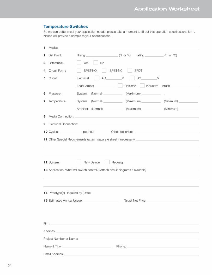
Temperature SwitchesSo we can better meet your application needs, please take a moment to fill out this operation specifications form.Nason will provide a sample to your specifications.
1 Media:
2 Set Point: Rising (°F or °C) Falling (°F or °C)
3 Differential: c Yes c No
4 Circuit Form: c SPST-NO c SPST-NC c SPDT
5 Circuit: Electrical c AC V c DC V
Load (Amps) c Resistive c Inductive Inrush
6 Pressure: System (Normal) (Maximum)
7 Temperature: System (Normal) (Maximum) (Minimum)
Ambient (Normal) (Maximum) (Minimum)
8 Media Connection:
9 Electrical Connection:
10 Cycles: per hour Other (describe):
11 Other Special Requirements (attach separate sheet if necessary):
12 System: c New Design c Redesign
13 Application: What will switch control? (Attach circuit diagrams if available)
14 Prototype(s) Required by (Date):
15 Estimated Annual Usage: Target Net Price:
Firm:
Address:
Project Number or Name:
Name & Title: Phone:
Email Address:
Application Worksheet

35 TR
ANS
DU
CER
S
TRANSDUCERS
• Three new models – NT100, NT40 and NT25
• Basic to highly customized models
• Hydraulic and pneumatic designs
• Models with accuracy ranges of 1%, .4% and .25%
• Vacuum ranges to 10,000 PSI
• IP69K seal available for the NT25, enabling high-pressure wash down capability
• Compact designs
• Custom outputs and ranges available
• Multiple industry applications
36
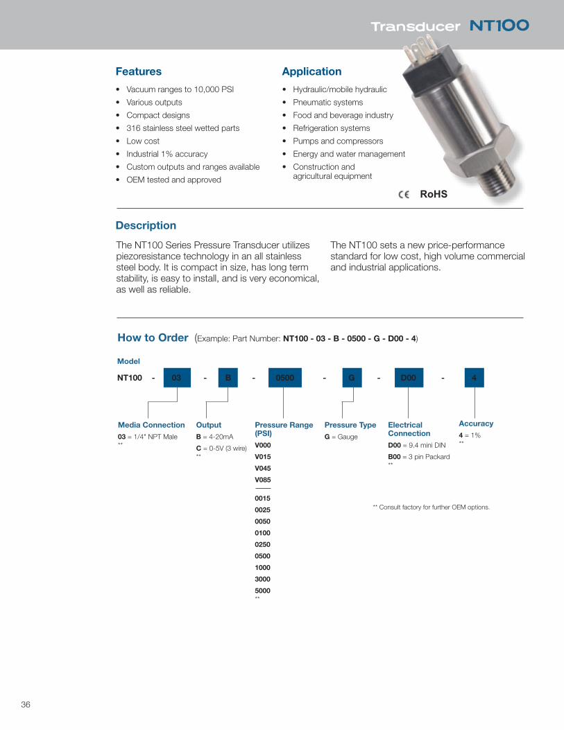
NT100
Features
• Vacuum ranges to 10,000 PSI
• Various outputs
• Compact designs
• 316 stainless steel wetted parts
• Low cost
• Industrial 1% accuracy
• Custom outputs and ranges available
• OEM tested and approved
The NT100 Series Pressure Transducer utilizes piezoresistance technology in an all stainless steel body. It is compact in size, has long term stability, is easy to install, and is very economical, as well as reliable.
The NT100 sets a new price-performance standard for low cost, high volume commercial and industrial applications.
Application
• Hydraulic/mobile hydraulic
• Pneumatic systems
• Food and beverage industry
• Refrigeration systems
• Pumps and compressors
• Energy and water management
• Construction and agricultural equipment
Description
How to Order (Example: Part Number: NT100 - 03 - B - 0500 - G - D00 - 4)
Model
NT100 - 03 - B - 0500 - G - D00 - 4
Media Connection
03 = 1/4" NPT Male**
Output
B = 4-20mA
C = 0-5V (3 wire)**
Pressure Range(PSI)
V000
V015
V045
V085
0015
0025
0050
0100
0250
0500
1000
3000
5000**
Pressure Type
G = Gauge
ElectricalConnection
D00 = 9.4 mini DIN
B00 = 3 pin Packard**
Accuracy
4 = 1%**
** Consult factory for further OEM options.
Transducer NT100
RoHS

37
Transducer NT100
Specifications
InputSupply Voltage 12-36 VDCPressure Range VAC to 10,000 PSIProof Pressure 1.5 x full scaleBurst Pressure 3 x full scaleFatigue Life More than 4 million cycles
PerformanceAccuracy 1%Stability 0.2% full scaleCompensated Temperatures -10 to 75°C (14 to 167°F)Operating Temperatures -20 to 80°C (-4 to 176°F)Zero and Span Offset Tolerance 1.5%
Mechanical ConfigurationPressure Port 1/4 NPT (standard) *Electrical Connection 9.4 mini DIN, 3 pin Packard *Sealing Rating IP65 with standard 9.4 DIN cableWetted Parts 316 stainless steel
For best performance, use shielded cables. Mating cable assemblies sold separately. * Consult factory for further OEM options.
Electrical Connections
Signal Function Color Pin Electrical Connector
0-5V Supply V + Red 1 DIN 4 pin (9.4)
Com Black 2 Output White 3 N/A N/A 4
4-20mA Supply V Red 1 Output Black 2
0-5V Com - A 3 pin Packard
Supply + - B Output + - C
4-20mA Output - A Supply + - B
12
3
4
A
C
B1 3
4
2
12
3
4
A
C
B1 3
4
2
65mm
25mm
25mm
65mm
38
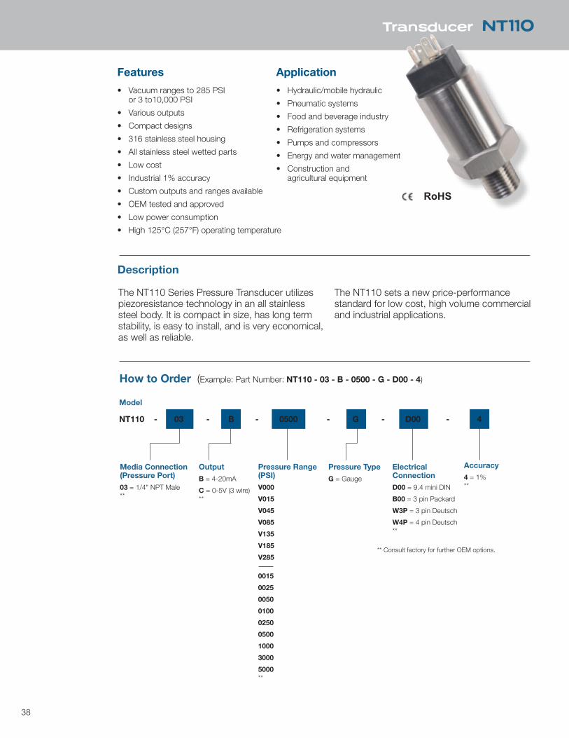
NT100
Features
• Vacuum ranges to 285 PSI or 3 to10,000 PSI
• Various outputs
• Compact designs
• 316 stainless steel housing
• All stainless steel wetted parts
• Low cost
• Industrial 1% accuracy
• Custom outputs and ranges available
• OEM tested and approved
• Low power consumption
• High 125°C (257°F) operating temperature
The NT110 Series Pressure Transducer utilizes piezoresistance technology in an all stainless steel body. It is compact in size, has long term stability, is easy to install, and is very economical, as well as reliable.
The NT110 sets a new price-performance standard for low cost, high volume commercial and industrial applications.
Application
• Hydraulic/mobile hydraulic
• Pneumatic systems
• Food and beverage industry
• Refrigeration systems
• Pumps and compressors
• Energy and water management
• Construction and agricultural equipment
Description
How to Order (Example: Part Number: NT110 - 03 - B - 0500 - G - D00 - 4)
Model
NT110 - 03 - B - 0500 - G - D00 - 4
Media Connection (Pressure Port)
03 = 1/4" NPT Male**
Output
B = 4-20mA
C = 0-5V (3 wire)**
Pressure Range(PSI)
V000
V015
V045
V085
V135
V185
V285
0015
0025
0050
0100
0250
0500
1000
3000
5000**
Pressure Type
G = Gauge
ElectricalConnection
D00 = 9.4 mini DIN
B00 = 3 pin Packard
W3P = 3 pin Deutsch
W4P = 4 pin Deutsch**
Accuracy
4 = 1%**
** Consult factory for further OEM options.
Transducer NT110
RoHS
39
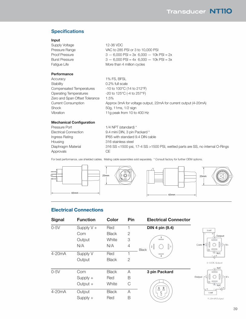
Transducer NT110
Specifications
InputSupply Voltage 12-36 VDCPressure Range VAC to 285 PSI or 3 to 10,000 PSIProof Pressure 3 — 6,000 PSI = 3x 6,000 — 10k PSI = 2xBurst Pressure 3 — 6,000 PSI = 4x 6,000 — 10k PSI = 3xFatigue Life More than 4 million cycles
PerformanceAccuracy 1% FS, BFSLStability 0.2% full scaleCompensated Temperatures -10 to 100°C (14 to 212°F)Operating Temperatures -20 to 125°C (-4 to 257°F)Zero and Span Offset Tolerance 1.5%Current Consumption Approx 3mA for voltage output, 22mA for current output (4-20mA)Shock 50g, 11ms, 1/2 signVibration 11g peak from 10 to 400 Hz
Mechanical ConfigurationPressure Port 1/4 NPT (standard) *Electrical Connection 9.4 mini DIN, 3 pin Packard *Ingress Rating IP65 with standard 9.4 DIN cableHousing 316 stainless steelDiaphragm Material 316 SS <1500 psi, 17-4 SS >1500 PSI, wetted parts are SS, no internal O-RingsApprovals CE
For best performance, use shielded cables. Mating cable assemblies sold separately. * Consult factory for further OEM options.
Electrical Connections
Signal Function Color Pin Electrical Connector
0-5V Supply V + Red 1 DIN 4 pin (9.4)
Com Black 2 Output White 3 N/A N/A 4
4-20mA Supply V Red 1 Output Black 2
0-5V Com Black A 3 pin Packard
Supply + Red B Output + White C
4-20mA Output Black A Supply + Red B
12
3
4
A
C
B1 3
4
2
12
3
4
A
C
B1 3
4
2
65mm
25mm
25mm
65mm
65mm
25mm
25mm
65mm65mm
25mm
25mm
65mm
65mm
25mm
25mm
65mm
Black
40
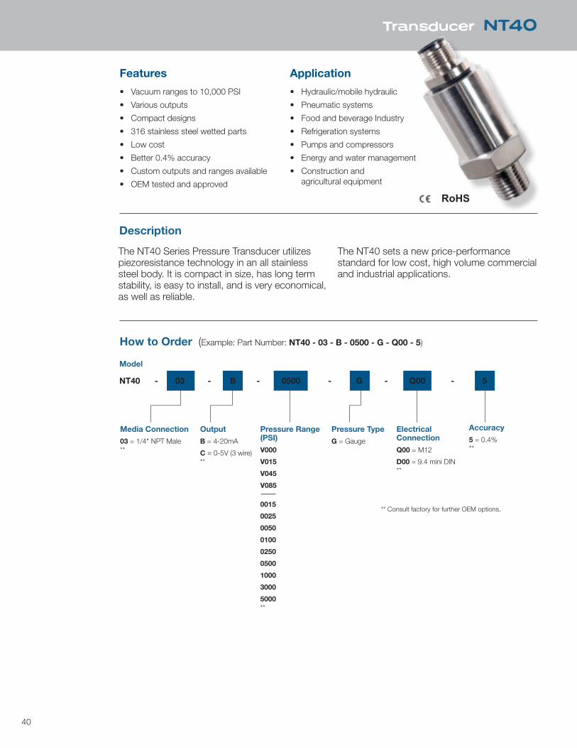
Features
• Vacuum ranges to 10,000 PSI
• Various outputs
• Compact designs
• 316 stainless steel wetted parts
• Low cost
• Better 0.4% accuracy
• Custom outputs and ranges available
• OEM tested and approved
Description
The NT40 Series Pressure Transducer utilizes piezoresistance technology in an all stainless steel body. It is compact in size, has long term stability, is easy to install, and is very economical, as well as reliable.
The NT40 sets a new price-performance standard for low cost, high volume commercial and industrial applications.
Application
• Hydraulic/mobile hydraulic
• Pneumatic systems
• Food and beverage Industry
• Refrigeration systems
• Pumps and compressors
• Energy and water management
• Construction and agricultural equipment
How to Order (Example: Part Number: NT40 - 03 - B - 0500 - G - Q00 - 5)
Model
NT40 - 03 - B - 0500 - G - Q00 - 5
Media Connection
03 = 1/4" NPT Male**
Output
B = 4-20mA
C = 0-5V (3 wire)**
Pressure Range(PSI)
V000
V015
V045
V085
0015
0025
0050
0100
0250
0500
1000
3000
5000**
Pressure Type
G = Gauge
ElectricalConnection
Q00 = M12
D00 = 9.4 mini DIN**
Accuracy
5 = 0.4%**
** Consult factory for further OEM options.
Transducer NT40
RoHS
41
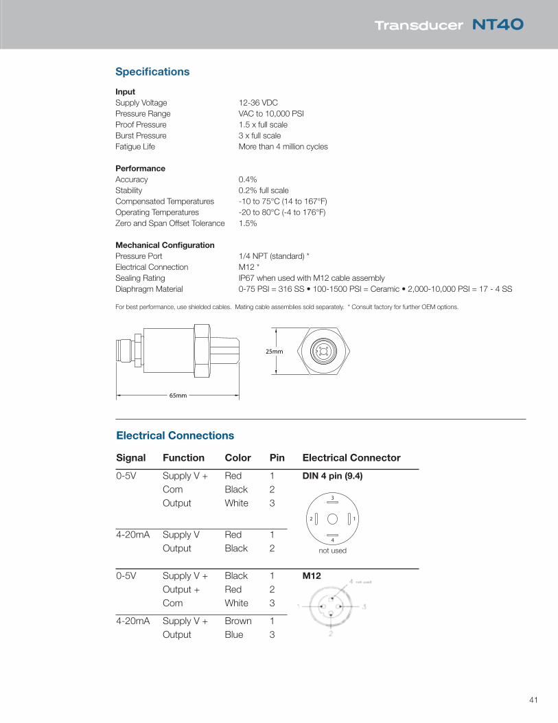
Specifications
InputSupply Voltage 12-36 VDCPressure Range VAC to 10,000 PSIProof Pressure 1.5 x full scaleBurst Pressure 3 x full scaleFatigue Life More than 4 million cycles
PerformanceAccuracy 0.4%Stability 0.2% full scaleCompensated Temperatures -10 to 75°C (14 to 167°F)Operating Temperatures -20 to 80°C (-4 to 176°F)Zero and Span Offset Tolerance 1.5%
Mechanical ConfigurationPressure Port 1/4 NPT (standard) *Electrical Connection M12 *Sealing Rating IP67 when used with M12 cable assemblyDiaphragm Material 0-75 PSI = 316 SS • 100-1500 PSI = Ceramic • 2,000-10,000 PSI = 17 - 4 SS
For best performance, use shielded cables. Mating cable assemblies sold separately. * Consult factory for further OEM options.
25mm
65mm
Transducer NT40
Electrical Connections
Signal Function Color Pin Electrical Connector
0-5V Supply V + Red 1 DIN 4 pin (9.4)
Com Black 2 Output White 3
4-20mA Supply V Red 1 Output Black 2
0-5V Supply V + Black 1 M12
Output + Red 2 Com White 3
4-20mA Supply V + Brown 1 Output Blue 3
12
3
4
A
C
B1 3
4
2 not used
42
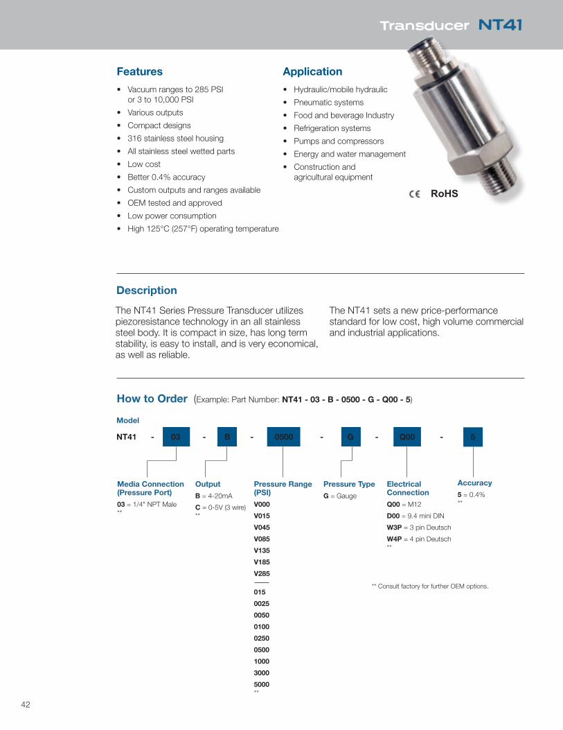
Features
• Vacuum ranges to 285 PSI or 3 to 10,000 PSI
• Various outputs
• Compact designs
• 316 stainless steel housing
• All stainless steel wetted parts
• Low cost
• Better 0.4% accuracy
• Custom outputs and ranges available
• OEM tested and approved
• Low power consumption
• High 125°C (257°F) operating temperature
Description
The NT41 Series Pressure Transducer utilizes piezoresistance technology in an all stainless steel body. It is compact in size, has long term stability, is easy to install, and is very economical, as well as reliable.
The NT41 sets a new price-performance standard for low cost, high volume commercial and industrial applications.
Application
• Hydraulic/mobile hydraulic
• Pneumatic systems
• Food and beverage Industry
• Refrigeration systems
• Pumps and compressors
• Energy and water management
• Construction and agricultural equipment
How to Order (Example: Part Number: NT41 - 03 - B - 0500 - G - Q00 - 5)
Model
NT41 - 03 - B - 0500 - G - Q00 - 5
Media Connection (Pressure Port)
03 = 1/4" NPT Male**
Output
B = 4-20mA
C = 0-5V (3 wire)**
Pressure Range(PSI)
V000
V015
V045
V085
V135
V185
V285
015
0025
0050
0100
0250
0500
1000
3000
5000**
Pressure Type
G = Gauge
ElectricalConnection
Q00 = M12
D00 = 9.4 mini DIN
W3P = 3 pin Deutsch
W4P = 4 pin Deutsch**
Accuracy
5 = 0.4%**
** Consult factory for further OEM options.
Transducer NT41
RoHS

43
x4 Pin1 Pin2 Pin3 Pin4
mA Output+ Supply+ N/C N/C
V COM Supply+ N/C Output+
Specifications
InputSupply Voltage 12-36 VDCPressure Range VAC to 10,000 PSIProof Pressure 1.5 x full scaleBurst Pressure 3 x full scaleFatigue Life More than 4 million cycles
PerformanceAccuracy 0.4%Stability 0.2% full scaleCompensated Temperatures -10 to 100°C (14 to 212°F)Operating Temperatures -20 to 125°C (-4 to 257°F)Zero and Span Offset Tolerance 1.5%
Mechanical ConfigurationPressure Port 1/4 NPT (standard) *Electrical Connection M12*, 3 pin Deutsch, 4 pin DeutschSealing Rating IP67 when used with M12 cable assemblyWetted Parts 316 stainless steel
For best performance, use shielded cables. Mating cable assemblies sold separately. * Consult factory for further OEM options.
25mm
65mm
Transducer NT41
Electrical Connections
Signal Function Color Pin Electrical Connector
0-5V Supply V + Brown 1 M12
Output + White 2 Com Blue 3
4-20mA Supply V Brown 1 Output Blue 3
44
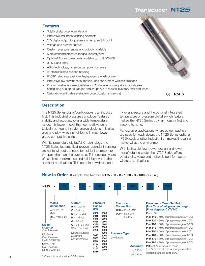
Features• Totally digital proprietary design
• Innovative redundant sensing elements
• 24V digital output for pressure or temp switch point
• Voltage and current outputs
• Custom pressure ranges and outputs available
• More standard pressure ranges, industry first
• Optional 4x over pressure is available up to 5,000 PSI
• 0.25% accuracy
• ASIC technology, no zero/span potentiometers
• All stainless steel welded housing
• IP-69K rated seal available (high pressure wash down)
• Innovative low current consumption, ideal for custom wireless solutions
• Programmable systems available for OEM/systems integrators for in-house configuring of outputs, ranges and set points to reduce inventory and lead times
• Calibration certificates available (contact customer service)
Description
The NT25 Series digital/configurable is an industry first. This industrial pressure transducer features stability and accuracy over a wide temperature range. It is lower in cost than competitive units typically not found in older analog designs. It is also plug and play, which is not found in most lower-grade competitive units.
With its proprietary digital/ASIC technology, the NT25 Series features field-proven redundant sensing elements without the need for solder in resistors or trim pots that can drift over time. This provides years of excellent performance and reliability even in the harshest applications. This combined with optional
4x over pressure and the optional integrated temperature or pressure digital switch feature, makes the NT25 Series truly an industry first and second to none.
For extreme applications where power washers are used for wash down, the NT25 Series optional IP69K seal, another industry first, makes it ideal no matter what the environment.
With its flexible, low-power design and lower manufacturing costs, the NT25 Series offers outstanding value and makes it ideal for custom wireless applications.
How to Order (Example: Part Number: NT25 - 03 - D - 1000 - G - Q00 - 2 - T40)
Media Connection03 = 1/4” NPT Male09 = 7/16” x 20**
OutputB = 4-20mAC = 0-5 vdcD = 0-10 vdcH = 1-5 vdcJ = 1-6 vdcG = 0.5-5.5 vdc W = 0.5-4.5 vdc
(voltage outputs are 3 wire non-ratiometric)
Pressure Range(PSI)
Pressure Type
G = Gauge
ElectricalConnectionQ00 = IP69K M12D00 = 4 pin Mini 9.4 DIN**
Accuracy
1 = 0.15%
2 = 0.25%** Consult factory for further OEM options.
Model NT25= 2X Over Pressure
NT26= 4X Over Pressure(up to 5000 PSI)
NT27= 10X Over Pressure(up to 2000 PSI)
Pressure or Temp Set Point (P or T) % of full pressure range (P) or degrees C (T) T40X = no SPP or T10 = 10% of pressure range or 10°CP or T20 = 20% of pressure range or 20°CP or T30 = 30% of pressure range or 30°CP or T40 = 40% of pressure range or 40°CP or T50 = 50% of pressure range or 50°CP or T60 = 60% of pressure range or 60°CP or T70 = 70% of pressure range or 70°CP or T80 = 80% of pressure range or 80°CP90 = 90% of pressure range(P = % of the full pressure range selected)(full temp range is 10 to 80°C)
NT25 - 03 - D - 1000 - G - Q00 - 2 - T40
Transducer NT25
RoHS
V000V015V045V085V135V185V285
0015 002500500100015002000250
0300040005000600070008000900100020003000400050006000010K
45
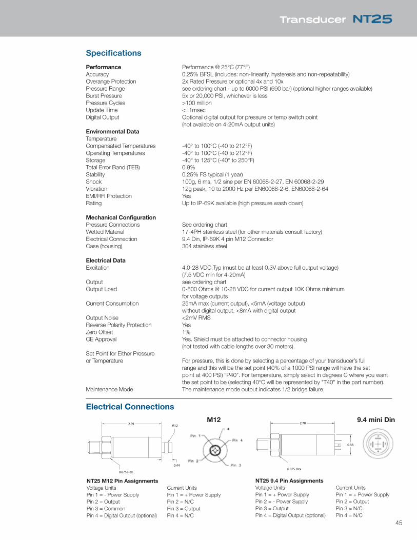
Specifications
Performance Performance @ 25°C (77°F)Accuracy 0.25% BFSL (includes: non-linearity, hysteresis and non-repeatability)Overange Protection 2x Rated Pressure or optional 4x and 10xPressure Range see ordering chart - up to 6000 PSI (690 bar) (optional higher ranges available)Burst Pressure 5x or 20,000 PSI, whichever is lessPressure Cycles >100 millionUpdate Time <=1msecDigital Output Optional digital output for pressure or temp switch point (not available on 4-20mA output units)Environmental DataTemperatureCompensated Temperatures -40° to 100°C (-40 to 212°F)Operating Temperatures -40° to 100°C (-40 to 212°F)Storage -40° to 125°C (-40° to 250°F)Total Error Band (TEB) 0.9%Stability 0.25% FS typical (1 year)Shock 100g, 6 ms, 1/2 sine per EN 60068-2-27, EN 60068-2-29Vibration 12g peak, 10 to 2000 Hz per EN60068-2-6, EN60068-2-64EMI/RFI Protection YesRating Up to IP-69K available (high pressure wash down)
Mechanical ConfigurationPressure Connections See ordering chartWetted Material 17-4PH stainless steel (for other materials consult factory)Electrical Connection 9.4 Din, IP-69K 4 pin M12 ConnectorCase (housing) 304 stainless steel
Electrical DataExcitation 4.0-28 VDC,Typ (must be at least 0.3V above full output voltage) (7.5 VDC min for 4-20mA)Output see ordering chartOutput Load 0-800 Ohms @ 10-28 VDC for current output 10K Ohms minimum for voltage outputsCurrent Consumption 25mA max (current output), <5mA (voltage output) without digital output, <8mA with digital outputOutput Noise <2mV RMSReverse Polarity Protection YesZero Offset 1%CE Approval Yes. Shield must be attached to connector housing (not tested with cable lengths over 30 meters).Set Point for Either Pressure or Temperature For pressure, this is done by selecting a percentage of your transducer’s full range and this will be the set point (40% of a 1000 PSI range will have the set point at 400 PSI) “P40”. For temperature, simply select in degrees C where you want the set point to be (selecting 40°C will be represented by "T40" in the part number).Maintenance Mode The maintenance mode output indicates 1/2 bridge failure.
2.59 2.78
0.44
M12
0.875 Hex0.875 Hex
0.88
Transducer NT25
M12 9.4 mini Din
NT25 9.4 Pin AssignmentsVoltage Units Current UnitsPin 1 = + Power Supply Pin 1 = + Power SupplyPin 2 = - Power Supply Pin 2 = OutputPin 3 = Output Pin 3 = N/CPin 4 = Digital Output (optional) Pin 4 = N/C
NT25 M12 Pin AssignmentsVoltage Units Current UnitsPin 1 = - Power Supply Pin 1 = + Power SupplyPin 2 = Output Pin 2 = N/CPin 3 = Common Pin 3 = OutputPin 4 = Digital Output (optional) Pin 4 = N/C
2.59 2.78
0.44
M12
0.875 Hex0.875 Hex
0.88
Electrical Connections
46
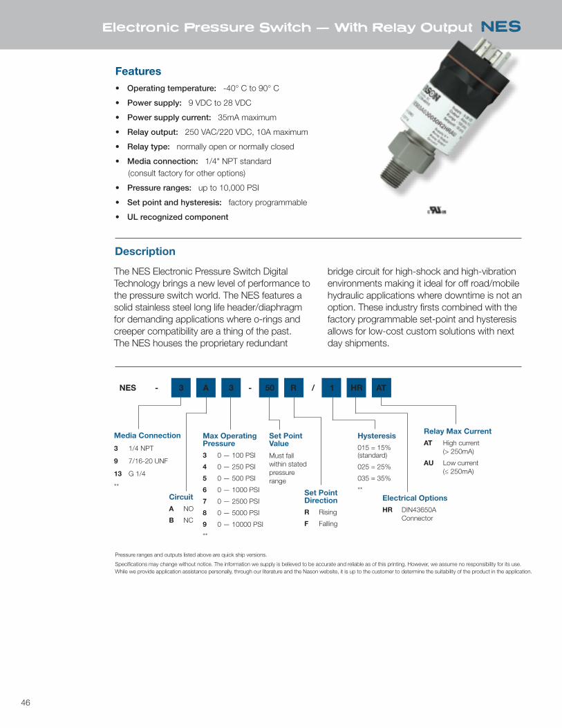
Features• Operating temperature: -40° C to 90° C
• Power supply: 9 VDC to 28 VDC
• Power supply current: 35mA maximum
• Relay output: 250 VAC/220 VDC, 10A maximum
• Relay type: normally open or normally closed
• Media connection: 1/4" NPT standard (consult factory for other options)
• Pressure ranges: up to 10,000 PSI
• Set point and hysteresis: factory programmable
• UL recognized component
Description
The NES Electronic Pressure Switch Digital Technology brings a new level of performance to the pressure switch world. The NES features a solid stainless steel long life header/diaphragm for demanding applications where o-rings and creeper compatibility are a thing of the past. The NES houses the proprietary redundant
bridge circuit for high-shock and high-vibration environments making it ideal for off road/mobile hydraulic applications where downtime is not an option. These industry firsts combined with the factory programmable set-point and hysteresis allows for low-cost custom solutions with next day shipments.
Electronic Pressure Switch — With Relay Output NES
Circuit
A NO
B NC
Media Connection
3 1/4 NPT
9 7/16-20 UNF
13 G 1/4
**
Max Operating Pressure
3 0 — 100 PSI
4 0 — 250 PSI
5 0 — 500 PSI
6 0 — 1000 PSI
7 0 — 2500 PSI
8 0 — 5000 PSI
9 0 — 10000 PSI
**
Electrical Options
HR DIN43650A Connector
Set Point Value
Must fall within stated pressure range
Set Point Direction
R Rising
F Falling
Hysteresis
015 = 15% (standard)
025 = 25%
035 = 35%
**
Relay Max Current
AT High current (> 250mA)
AU Low current (≤ 250mA)
NES - 3 A 3 - 50 R / 1 HR AT
Pressure ranges and outputs listed above are quick ship versions.
Specifications may change without notice. The information we supply is believed to be accurate and reliable as of this printing. However, we assume no responsibility for its use. While we provide application assistance personally, through our literature and the Nason website, it is up to the customer to determine the suitability of the product in the application.
47
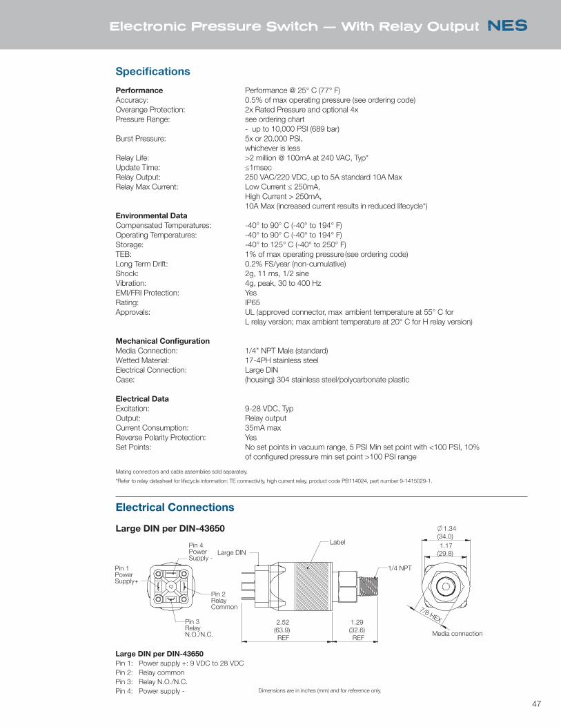
Specifications
Performance Performance @ 25° C (77° F)Accuracy: 0.5% of max operating pressure (see ordering code)Overange Protection: 2x Rated Pressure and optional 4x Pressure Range: see ordering chart - up to 10,000 PSI (689 bar)Burst Pressure: 5x or 20,000 PSI, whichever is lessRelay Life: >2 million @ 100mA at 240 VAC, Typ*Update Time: ≤1msecRelay Output: 250 VAC/220 VDC, up to 5A standard 10A MaxRelay Max Current: Low Current ≤ 250mA, High Current > 250mA, 10A Max (increased current results in reduced lifecycle*)Environmental DataCompensated Temperatures: -40° to 90° C (-40° to 194° F) Operating Temperatures: -40° to 90° C (-40° to 194° F) Storage: -40° to 125° C (-40° to 250° F)TEB: 1% of max operating pressure (see ordering code)Long Term Drift: 0.2% FS/year (non-cumulative)Shock: 2g, 11 ms, 1/2 sine Vibration: 4g, peak, 30 to 400 HzEMI/FRI Protection: YesRating: IP65Approvals: UL (approved connector, max ambient temperature at 55° C for L relay version; max ambient temperature at 20° C for H relay version)
Mechanical ConfigurationMedia Connection: 1/4" NPT Male (standard)Wetted Material: 17-4PH stainless steel Electrical Connection: Large DIN Case: (housing) 304 stainless steel/polycarbonate plastic
Electrical DataExcitation: 9-28 VDC, TypOutput: Relay outputCurrent Consumption: 35mA maxReverse Polarity Protection: YesSet Points: No set points in vacuum range, 5 PSI Min set point with <100 PSI, 10% of configured pressure min set point >100 PSI range
Electronic Pressure Switch — With Relay Output NES
Large DIN per DIN-43650
Electrical Connections
Mating connectors and cable assemblies sold separately.
*Refer to relay datasheet for lifecycle information: TE connectivity, high current relay, product code PB114024, part number 9-1415029-1.
Large DIN per DIN-43650Pin 1: Power supply +: 9 VDC to 28 VDCPin 2: Relay commonPin 3: Relay N.O./N.C.Pin 4: Power supply - Dimensions are in inches (mm) and for reference only.
1.29 (32.6)REF
2.52(63.9)REF
LabelLarge DIN
1/4 NPT
7/8 HEX
1.17(29.8)
1.34(34.0)
Pin 2RelayCommon
Pin 3RelayN.O./N.C.
Pin 1PowerSupply+
Media connection
Pin 4PowerSupply -Pressure ranges and outputs listed above are quick ship versions.
Specifications may change without notice. The information we supply is believed to be accurate and reliable as of this printing. However, we assume no responsibility for its use. While we provide application assistance personally, through our literature and the Nason website, it is up to the customer to determine the suitability of the product in the application.
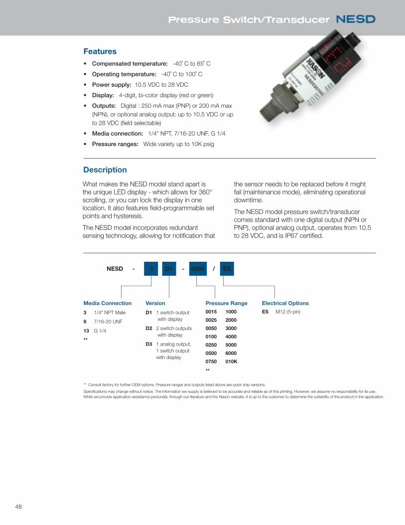
48
Features• Compensated temperature: -40˚ C to 85˚ C
• Operating temperature: -40˚ C to 100˚ C
• Power supply: 10.5 VDC to 28 VDC
• Display: 4-digit, bi-color display (red or green)
• Outputs: Digital : 250 mA max (PNP) or 200 mA max (NPN), or optional analog output: up to 10.5 VDC or up to 28 VDC (field selectable)
• Media connection: 1/4" NPT, 7/16-20 UNF, G 1/4
• Pressure ranges: Wide variety up to 10K psig
Description
What makes the NESD model stand apart is the unique LED display - which allows for 360° scrolling, or you can lock the display in one location. It also features field-programmable set points and hysteresis.
The NESD model incorporates redundant sensing technology, allowing for notification that
the sensor needs to be replaced before it might fail (maintenance mode), eliminating operational downtime.
The NESD model pressure switch/transducer comes standard with one digital output (NPN or PNP), optional analog output, operates from 10.5 to 28 VDC, and is IP67 certified.
Pressure Switch/Transducer NESD
Version
D1 1 switch output with display
D2 2 switch outputs with display
D3 1 analog output, 1 switch output with display
Media Connection
3 1/4" NPT Male
9 7/16-20 UNF
13 G 1/4
**
Pressure Range
0015 1000
0025 2000
0050 3000
0100 4000
0250 5000
0500 6000
0750 010K
**
Electrical Options
ES M12 (5-pin)
NESD - 3 D1 - 0050 / ES
** Consult factory for further OEM options. Pressure ranges and outputs listed above are quick ship versions.
Specifications may change without notice. The information we supply is believed to be accurate and reliable as of this printing. However, we assume no responsibility for its use. While we provide application assistance personally, through our literature and the Nason website, it is up to the customer to determine the suitability of the product in the application.
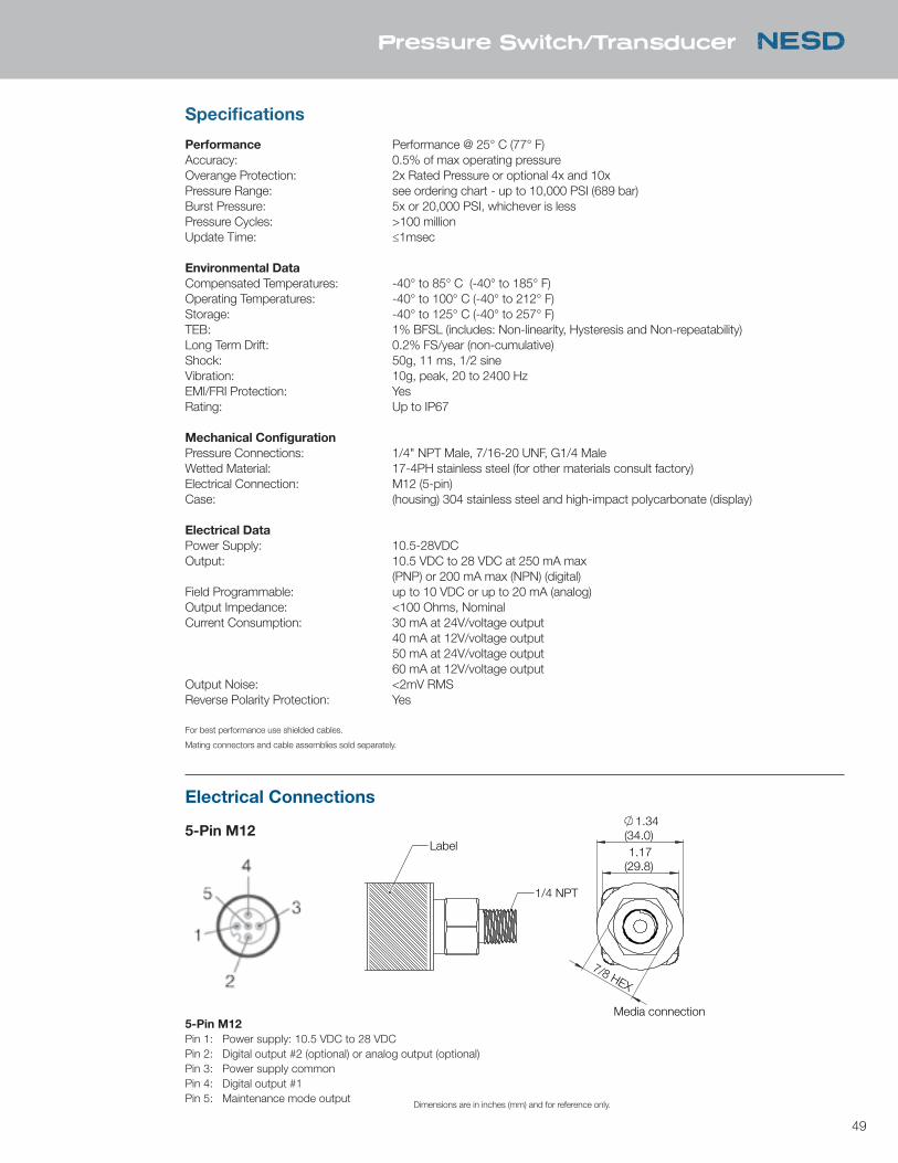
49
Specifications
Performance Performance @ 25° C (77° F)Accuracy: 0.5% of max operating pressureOverange Protection: 2x Rated Pressure or optional 4x and 10x Pressure Range: see ordering chart - up to 10,000 PSI (689 bar)Burst Pressure: 5x or 20,000 PSI, whichever is less Pressure Cycles: >100 million Update Time: ≤1msec
Environmental DataCompensated Temperatures: -40° to 85° C (-40° to 185° F) Operating Temperatures: -40° to 100° C (-40° to 212° F) Storage: -40° to 125° C (-40° to 257° F)TEB: 1% BFSL (includes: Non-linearity, Hysteresis and Non-repeatability)Long Term Drift: 0.2% FS/year (non-cumulative)Shock: 50g, 11 ms, 1/2 sine Vibration: 10g, peak, 20 to 2400 HzEMI/FRI Protection: YesRating: Up to IP67
Mechanical ConfigurationPressure Connections: 1/4" NPT Male, 7/16-20 UNF, G1/4 MaleWetted Material: 17-4PH stainless steel (for other materials consult factory)Electrical Connection: M12 (5-pin) Case: (housing) 304 stainless steel and high-impact polycarbonate (display)
Electrical DataPower Supply: 10.5-28VDCOutput: 10.5 VDC to 28 VDC at 250 mA max (PNP) or 200 mA max (NPN) (digital) Field Programmable: up to 10 VDC or up to 20 mA (analog)Output Impedance: <100 Ohms, Nominal Current Consumption: 30 mA at 24V/voltage output 40 mA at 12V/voltage output 50 mA at 24V/voltage output 60 mA at 12V/voltage outputOutput Noise: <2mV RMS Reverse Polarity Protection: Yes
Pressure Switch/Transducer NESD
5-Pin M12
Electrical Connections
5-Pin M12Pin 1: Power supply: 10.5 VDC to 28 VDCPin 2: Digital output #2 (optional) or analog output (optional)Pin 3: Power supply commonPin 4: Digital output #1Pin 5: Maintenance mode output
Dimensions are in inches (mm) and for reference only.
** Consult factory for further OEM options. Pressure ranges and outputs listed above are quick ship versions.
Specifications may change without notice. The information we supply is believed to be accurate and reliable as of this printing. However, we assume no responsibility for its use. While we provide application assistance personally, through our literature and the Nason website, it is up to the customer to determine the suitability of the product in the application.
For best performance use shielded cables.
Mating connectors and cable assemblies sold separately.
LabelLarge DIN
1/4 NPT
7/8 HEX
1.17(29.8)
1.34(34.0)
Pin 2RelayCommon
Pin 3RelayN.O./N.C.
Pin 1PowerSupply+
Media connection
Pin 4PowerSupply -
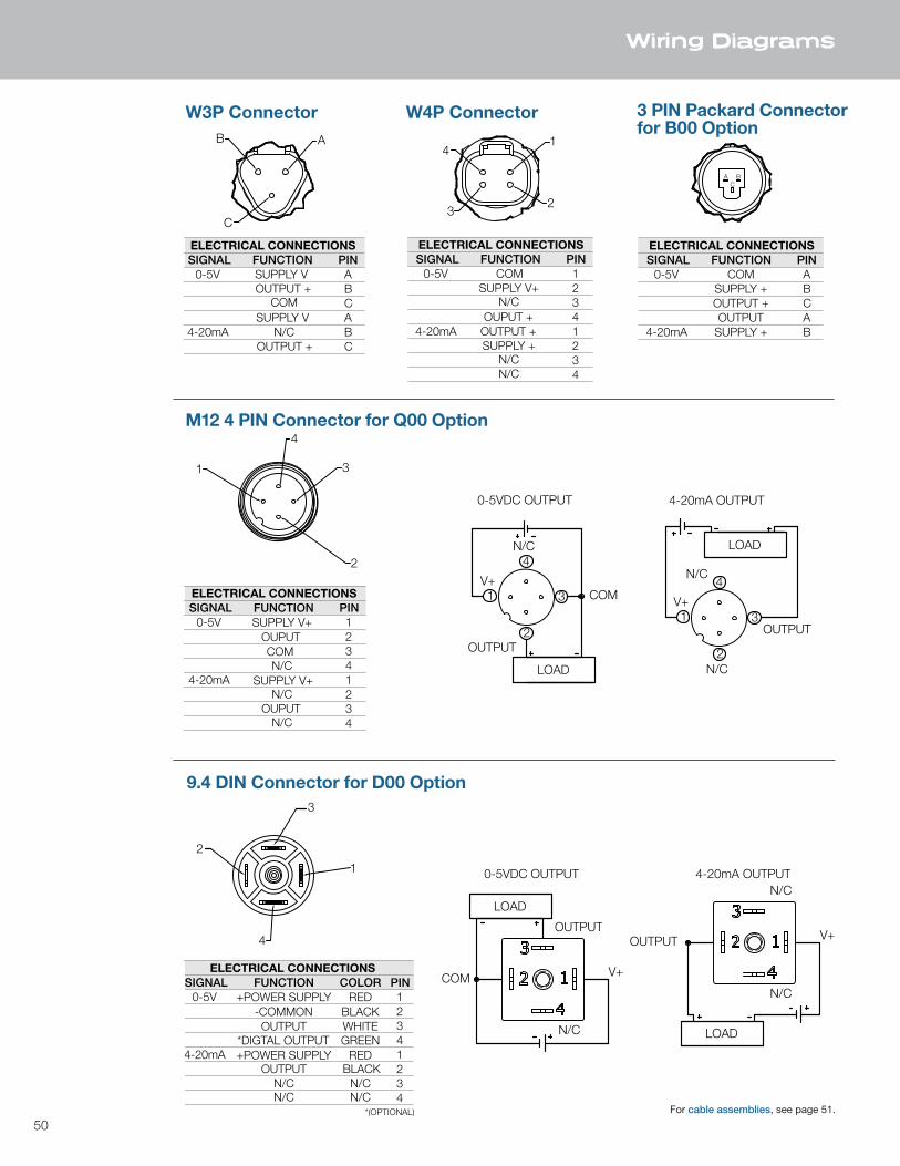
50
Wiring Diagrams
AB
C
ELECTRICAL CONNECTIONSSIGNAL FUNCTION PIN
0-5V SUPPLY V AOUTPUT + B
COM CSUPPLY V A
4-20mA N/C BOUTPUT + C
2
3
4
1
ELECTRICAL CONNECTIONSSIGNAL FUNCTION PIN
0-5V
COM
1SUPPLY V+2
N/C3
OUPUT
44-20mA 1
2N/C3
N/C 4
SUPPLY V+
OUPUT
2
3
4
1
LOAD
N/C
COMV+
OUTPUT
0-5VDC OUTPUT
2
3
4
1
LOAD
N/C
V+
OUTPUT
N/C
4-20mA OUTPUT
1
23
4
ELECTRICAL CONNECTIONSSIGNAL FUNCTION PIN
0-5V COM 1SUPPLY V+ 2
N/C 3OUPUT + 4
4-20mA OUTPUT + 1SUPPLY + 2
N/C 3N/C 4
A BC
ELECTRICAL CONNECTIONSSIGNAL FUNCTION PIN
0-5V COM ASUPPLY + BOUTPUT + COUTPUT A
4-20mA SUPPLY + B
ELECTRICAL CONNECTIONSSIGNAL FUNCTION PIN
0-5V
OUTPUT
1+POWER SUPPLY2
*DIGTAL OUTPUT
*(OPTIONAL)
3-COMMON
44-20mA 1
2OUTPUT3
N/C 4
+POWER SUPPLY
N/C
COLOR
WHITE
RED
GREEN
BLACK
BLACK
N/C
RED
N/C
4
1
3
2
LOAD
COM
N/C
V+
0-5VDC OUTPUT
LOAD
OUTPUT
N/C
V+
4-20mA OUTPUT
OUTPUT
N/C
W3P Connector W4P Connector 3 PIN Packard Connectorfor B00 Option
M12 4 PIN Connector for Q00 Option
9.4 DIN Connector for D00 Option
For cable assemblies, see page 51.

51
Cable Assemblies
PART # * = LENGTHNTCM1251 1 METERNTCM1253 3 METERS
1
2
34
1
4
3
2
+
bn
bk
-
bu
wh
1. +VOLTAGE2. LOAD3. COMMON4. LOAD5. MM OUTPUT
5
5gry
1
2
34
1
4
3
2
+
bn
bk
-
bu
wh
1. +VOLTAGE2. LOAD3. COMMON4. LOAD
1
4
3
2
rd
gr
+
wh
bk
1. +VOLTAGE2. COM3. LOAD4. N/C
-
A BC
A
B
C
+
bk
-
rd
wh
A. COMMONB. +VOLTAGEC. OUTPUT
1. RED2. BLACK3. WHITE4. GREEN
1. BROWN2. WHITE3. BLUE4. BLACK5. GREY
1. BROWN2. WHITE3. BLUE4. BLACK
A. BLACKB. REDC. WHITE
CABLE: PUR - 4 X 22AWG SHIELDED
CABLE: PVC - 5 X 22AWG SHIELDED
CABLE: PVC - 4 X 22AWG CABLE: PUR - 4 X 22AWG SHIELDED
PART # * = LENGTHNTC91 1 METERNTC93 3 METERS
PART # * = LENGTHNTCPA1 1 METERNTCPA3 3 METERS
PART # * = LENGTHNTCM121 1 METERNTCM123 3 METER
9.4mm DIN Cable Assembly M12, 5 PIN IP67K Cable Assembly
3 PIN Packard Cable Assembly M12, 4 PIN IP69K Cable Assembly
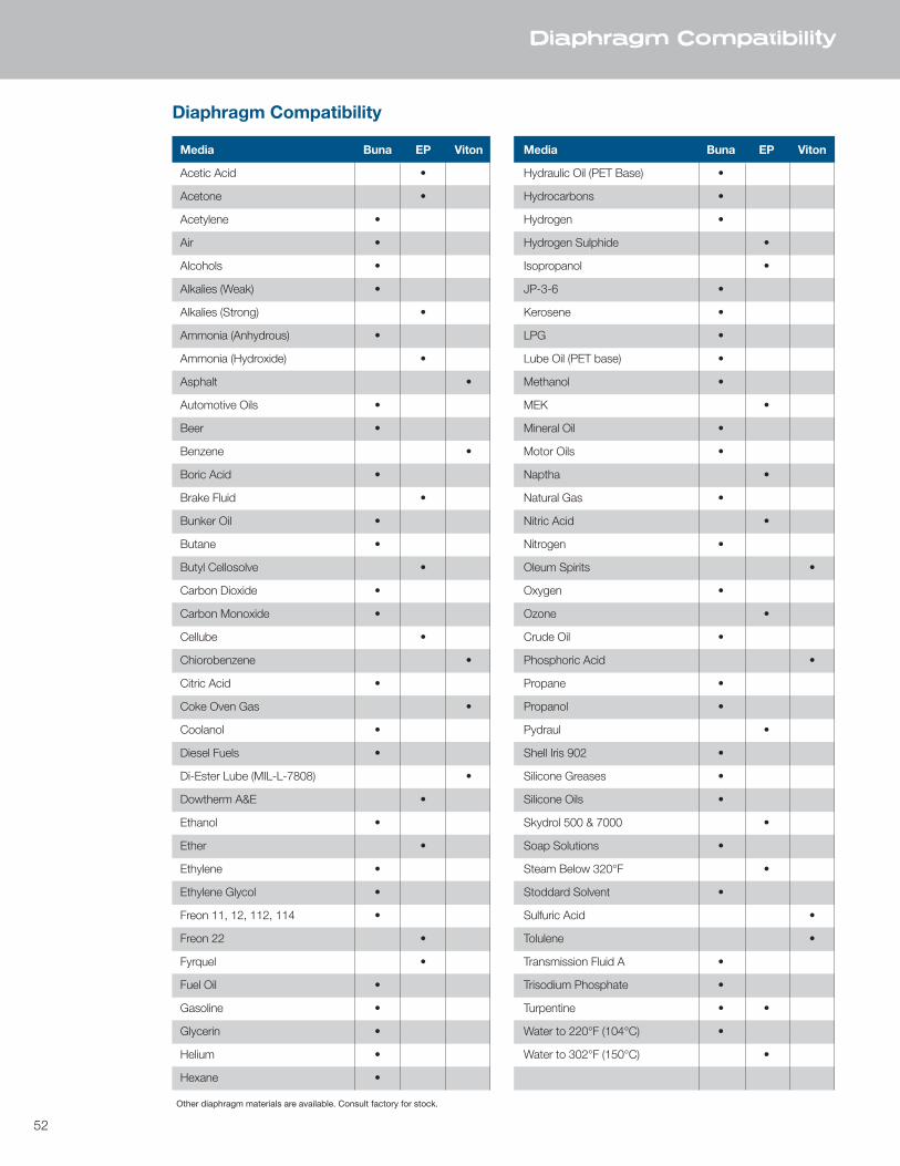
52
Diaphragm Compatibility
Media Buna EP Viton
Acetic Acid •
Acetone •
Acetylene •
Air •
Alcohols •
Alkalies (Weak) •
Alkalies (Strong) •
Ammonia (Anhydrous) •
Ammonia (Hydroxide) •
Asphalt •
Automotive Oils •
Beer •
Benzene •
Boric Acid •
Brake Fluid •
Bunker Oil •
Butane •
Butyl Cellosolve •
Carbon Dioxide •
Carbon Monoxide •
Cellube •
Chiorobenzene •
Citric Acid •
Coke Oven Gas •
Coolanol •
Diesel Fuels •
Di-Ester Lube (MIL-L-7808) •
Dowtherm A&E •
Ethanol •
Ether •
Ethylene •
Ethylene Glycol •
Freon 11, 12, 112, 114 •
Freon 22 •
Fyrquel •
Fuel Oil •
Gasoline •
Glycerin •
Helium •
Hexane •
Media Buna EP Viton
Hydraulic Oil (PET Base) •
Hydrocarbons •
Hydrogen •
Hydrogen Sulphide •
Isopropanol •
JP-3-6 •
Kerosene •
LPG •
Lube Oil (PET base) •
Methanol •
MEK •
Mineral Oil •
Motor Oils •
Naptha •
Natural Gas •
Nitric Acid •
Nitrogen •
Oleum Spirits •
Oxygen •
Ozone •
Crude Oil •
Phosphoric Acid •
Propane •
Propanol •
Pydraul •
Shell Iris 902 •
Silicone Greases •
Silicone Oils •
Skydrol 500 & 7000 •
Soap Solutions •
Steam Below 320°F •
Stoddard Solvent •
Sulfuric Acid •
Tolulene •
Transmission Fluid A •
Trisodium Phosphate •
Turpentine • •
Water to 220°F (104°C) •
Water to 302°F (150°C) •
Other diaphragm materials are available. Consult factory for stock.
Diaphragm Compatibility
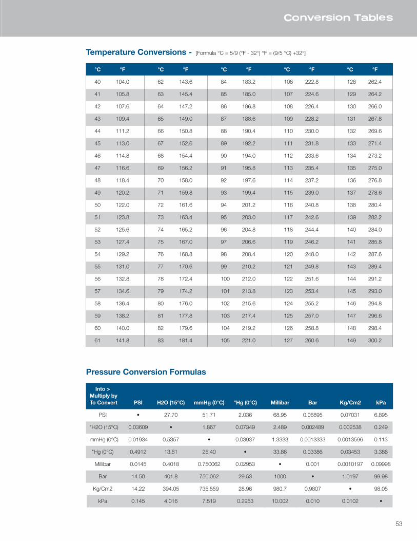
53
Conversion Tables
°C °F
40 104.0
41 105.8
42 107.6
43 109.4
44 111.2
45 113.0
46 114.8
47 116.6
48 118.4
49 120.2
50 122.0
51 123.8
52 125.6
53 127.4
54 129.2
55 131.0
56 132.8
57 134.6
58 136.4
59 138.2
60 140.0
61 141.8
°C °F
62 143.6
63 145.4
64 147.2
65 149.0
66 150.8
67 152.6
68 154.4
69 156.2
70 158.0
71 159.8
72 161.6
73 163.4
74 165.2
75 167.0
76 168.8
77 170.6
78 172.4
79 174.2
80 176.0
81 177.8
82 179.6
83 181.4
°C °F
84 183.2
85 185.0
86 186.8
87 188.6
88 190.4
89 192.2
90 194.0
91 195.8
92 197.6
93 199.4
94 201.2
95 203.0
96 204.8
97 206.6
98 208.4
99 210.2
100 212.0
101 213.8
102 215.6
103 217.4
104 219.2
105 221.0
°C °F
106 222.8
107 224.6
108 226.4
109 228.2
110 230.0
111 231.8
112 233.6
113 235.4
114 237.2
115 239.0
116 240.8
117 242.6
118 244.4
119 246.2
120 248.0
121 249.8
122 251.6
123 253.4
124 255.2
125 257.0
126 258.8
127 260.6
°C °F
128 262.4
129 264.2
130 266.0
131 267.8
132 269.6
133 271.4
134 273.2
135 275.0
136 276.8
137 278.6
138 280.4
139 282.2
140 284.0
141 285.8
142 287.6
143 289.4
144 291.2
145 293.0
146 294.8
147 296.6
148 298.4
149 300.2
Temperature Conversions - [Formula °C = 5/9 (°F - 32°) °F = (9/5 °C) +32°]
Into > Multiply by To Convert PSI H2O (15°C) mmHg (0°C) "Hg (0°C) Millibar Bar Kg/Cm2 kPa
PSI • 27.70 51.71 2.036 68.95 0.06895 0.07031 6.895
"H2O (15°C) 0.03609 • 1.867 0.07349 2.489 0.002489 0.002538 0.249
mmHg (0°C) 0.01934 0.5357 • 0.03937 1.3333 0.0013333 0.0013596 0.113
"Hg (0°C) 0.4912 13.61 25.40 • 33.86 0.03386 0.03453 3.386
Millibar 0.0145 0.4018 0.750062 0.02953 • 0.001 0.0010197 0.09998
Bar 14.50 401.8 750.062 29.53 1000 • 1.0197 99.98
Kg/Cm2 14.22 394.05 735.559 28.96 980.7 0.9807 • 98.05
kPa 0.145 4.016 7.519 0.2953 10.002 0.010 0.0102 •
Pressure Conversion Formulas
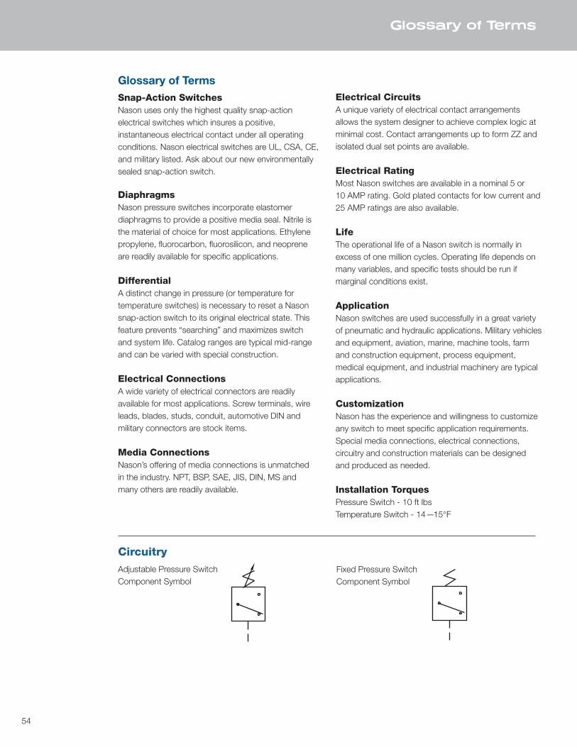
54
Glossary of Terms
Glossary of TermsSnap-Action SwitchesNason uses only the highest quality snap-actionelectrical switches which insures a positive, instantaneous electrical contact under all operating conditions. Nason electrical switches are UL, CSA, CE, and military listed. Ask about our new environmentally sealed snap-action switch.
DiaphragmsNason pressure switches incorporate elastomerdiaphragms to provide a positive media seal. Nitrile isthe material of choice for most applications. Ethylenepropylene, fluorocarbon, fluorosilicon, and neopreneare readily available for specific applications.
DifferentialA distinct change in pressure (or temperature fortemperature switches) is necessary to reset a Nasonsnap-action switch to its original electrical state. Thisfeature prevents “searching” and maximizes switchand system life. Catalog ranges are typical mid-rangeand can be varied with special construction.
Electrical ConnectionsA wide variety of electrical connectors are readilyavailable for most applications. Screw terminals, wireleads, blades, studs, conduit, automotive DIN andmilitary connectors are stock items.
Media ConnectionsNason’s offering of media connections is unmatchedin the industry. NPT, BSP, SAE, JIS, DIN, MS and many others are readily available.
Electrical CircuitsA unique variety of electrical contact arrangements allows the system designer to achieve complex logic at minimal cost. Contact arrangements up to form ZZ and isolated dual set points are available.
Electrical RatingMost Nason switches are available in a nominal 5 or10 AMP rating. Gold plated contacts for low current and25 AMP ratings are also available.
LifeThe operational life of a Nason switch is normally inexcess of one million cycles. Operating life depends onmany variables, and specific tests should be run ifmarginal conditions exist.
ApplicationNason switches are used successfully in a great variety of pneumatic and hydraulic applications. Military vehicles and equipment, aviation, marine, machine tools, farm and construction equipment, process equipment, medical equipment, and industrial machinery are typical applications.
CustomizationNason has the experience and willingness to customizeany switch to meet specific application requirements.Special media connections, electrical connections, circuitry and construction materials can be designed and produced as needed.
Installation TorquesPressure Switch - 10 ft lbsTemperature Switch - 14—15°F
CircuitryAdjustable Pressure SwitchComponent Symbol
Fixed Pressure SwitchComponent Symbol
1307 S Highway 11 • Walhalla SC 29691800.229.4955 • Phone: 864.638.9521Fax: 864.638.7903 • Orders: 800.229.4955www.nasonptc.com
For Nason’s catalog of pneumatic and hydraulic
automation productscall toll-free 800.229.4955
or visit our website at www.nasonptc.com
WARRANTY:
It is the sole responsibility of the user to determine the suitability of any product or information supplied by Nason for any application or use by the user.
ALL ORDERS FOR PRODUCT ARE SUBJECT TO THE FOLLOWING: Nason warrantseach product to be free from defects in material and workmanship under normal use andservice. Nason’s obligation under this warranty is limited to repairing or supplying, at ouroption, a part or parts to replace any defective part or parts which fail, within one (1) yearfrom date of shipment. No product shall be returned without prior authorization. Ifauthorized, the transportation charges shall be prepaid to Nason, Walhalla, SouthCarolina. Unauthorized returns will not be accepted.
The provisions of this warranty shall not apply to any part or parts which have been subjectto misuse, negligence or accident, or which have been repaired or altered in any way so asin the judgment of Nason to affect adversely its performance, stability or reliability.
Nason neither assumes nor authorizes anyone to assume for it any other obligation orliability for any loss or damage, either direct, incidental or consequential, resulting from orarising out of or in connection with any of its defective part or parts.
THIS WARRANTY IS EXPRESSLY IN LIEU OF ANY AND ALL OTHER WARRANTIES,EXPRESSED OR IMPLIED, INCLUDING ANY IMPLIED WARRANTY OF MERCHANTABILITYOR FITNESS FOR A PARTICULAR PURPOSE, AND OF ANY OTHER OBLIGATION ORLIABILITY ON THE PART OF NASON OF ANY NATURE WHATSOEVER.
NAS-SW 9/16
CHECK OUTnasonptc.com/configureto create your own custom CAD file
All NASON products are made in the USA.