Embed Size (px)
DESCRIPTION
prociding nanoparticles CuO
Citation preview

Seediscussions,stats,andauthorprofilesforthispublicationat:http://www.researchgate.net/publication/264222579
FacileSynthesisofCopperOxideNanoparticlesviaElectrospinning
DATASETinJOURNALOFNANOMATERIALS·JULY2014
ImpactFactor:1.64·DOI:10.1155/2014/438407
CITATIONS
3
READS
72
4AUTHORS,INCLUDING:
AbdullahKhalil
MasdarInstituteofScienceandTechnology
20PUBLICATIONS81CITATIONS
SEEPROFILE
MustaphaJouiad
MasdarInstituteofScienceandTechnology
48PUBLICATIONS292CITATIONS
SEEPROFILE
Allin-textreferencesunderlinedinbluearelinkedtopublicationsonResearchGate,
lettingyouaccessandreadthemimmediately.
Availablefrom:MustaphaJouiad
Retrievedon:20December2015
Research ArticleFacile Synthesis of Copper Oxide Nanoparticlesvia Electrospinning
Abdullah Khalil,1 Mustapha Jouiad,1 Marwan Khraisheh,2 and Raed Hashaikeh1
1 Department of Mechanical andMaterials Engineering, Masdar Institute of Science and Technology, P.O. Box 54224, Abu Dhabi, UAE2Qatar Environment and Energy Research Institute, Qatar Foundation, Doha, Qatar
Correspondence should be addressed to Raed Hashaikeh; [email protected]
Received 13 March 2014; Accepted 16 June 2014; Published 22 July 2014
Academic Editor: Shijun Liao
Copyright © 2014 Abdullah Khalil et al.This is an open access article distributed under theCreative CommonsAttribution License,which permits unrestricted use, distribution, and reproduction in any medium, provided the original work is properly cited.
A novel approach for synthesizing copper oxide (CuO) nanoparticles (NPs) through electrospinning is reported. The approach isbased on producing rough and discontinuous electrospun nanofibers from a precursor based on copper acetate salt and polyvinylalcohol (PVA) polymer. Selectively removing the polymeric phase from the fibers produced highly rough CuO nanofibers, whichwere composed of NPs that are weakly held together in a one-dimensional (1D) manner. Sonication in a suitable liquid undercontrolled conditions completely disintegrated the nanofibers intoNPs, resulting in the formation of uniformCuONPs suspension.Aberration corrected high resolution transmission electron microscope (HRTEM) showed that the obtained NPs are highlycrystalline and nearly sphere-like with a diameter of 30 to 70 nm.Thus, electrospinning, which is a low cost and industrially scalabletechnique, can also be employed for economic and large scale synthesis of NPs.
1. Introduction
Electrospinning, which came to light more than sevendecades ago [1], turned out to be such a powerful andversatile technique for continuous and large scale productionof nanofibers. The process involves the application of strongelectric field to generate electrically charged jet from the vis-cous solution through a tiny nozzle. As the electrical potentialovercomes the surface tension of the solution droplet comingout of the nozzle, the jet emerges from the droplet end andcontinues to thin as it approaches the collector. The solventsevaporate from the jet to form fibers having diameter ofthe orders of nanometer which are collected on a groundedelectrode. The process has been extensively employed forfabricating a variety of polymeric nanofibers [2]. Also, byvarying the electrospinning configuration and environmentalparameters, fibers with varying morphology such as porousand core-shell [3] can also be produced. Moreover, by addinga certain salt in specific proportion to the polymeric pre-cursor, nanofibers of various ceramics can also be obtainedafter selectively removing the polymeric phase through heattreatment [4–6].
Recently, electrospinning has also been employed forproducing metallic nanowires following the same approach[7, 8]. The approach is similar except one additional step ofreduction to transform the metal oxide nanofibers into puremetal nanowires.
Whereas the use of electrospinning process is limitedto the production of mats made out of nanofibers to date,we have found this process to be capable of producingnanoparticles (NPs) as well. We demonstrate this approachthrough an example of copper (II) oxide (CuO) NPs—anarrow band gap semiconducting material having potentialcatalytic [9], sensing [10], antimicrobial [11, 12], heat transfer[13, 14], and photovoltaic [15] applications because of theirhigh surface to volume ratio as compared to bulk counterpartand quantum confinement effects [16].
It is worth noticing that several physical methods such aslaser ablation [17] and microwave irradiation [18] and chem-ical techniques such as alcohothermal method [19, 20] andfast precipitation [21, 22] have been applied for synthesizingCuO NPs. However, these processes are costly in terms ofenergy consumption and setup requirements and hence notfeasible for economic mass production at the industrial scale.
Hindawi Publishing CorporationJournal of NanomaterialsVolume 2014, Article ID 438407, 7 pageshttp://dx.doi.org/10.1155/2014/438407
2 Journal of Nanomaterials
In addition, other techniques such as “supercritical waterhydrothermal synthesis” have been reported asmore versatileapproaches for producing NPs at the industrial scale and in acontinuousmanner [23]. Indeed, large variety of ceramicNPsin various size ranges have been synthesized in bulk quantitiesusing this technique [24, 25].
In contrast, we report here electrospinning, which isan economic and industrially scalable technique [26], as analternative and novel route for quick, low cost, and largescale production of NPs. We demonstrate this concept withthe example of electrospun CuO nanofibers transforming toCuO NPs. Similar approach can be adopted for synthesizinga variety of other NPs based on the appropriate precursorcomposition used for electrospinning.
2. Materials and Methods
The viscous and uniform precursor, based on copper (II)acetate (Sigma-Aldrich) and polyvinyl alcohol (PVA) (𝑀
𝑤=
61000, Sigma-Aldrich), was electrospun at a flow rate of0.2mL/hr and a voltage of 29 kV. The details of precursorpreparation, the optimized electrospinning parameters andthe post-treatment conditions of fibers were based on ourprevious investigation [27]. In a typical experiment forconverting the nanofibers to NPs, around 25mg of calcinednanofibers was transferred to a beaker containing 50mLof water. This mixture was then ultrasonicated using probesonication for 15min. This step resulted in the formationof transparent NPs suspension of CuO in water. The mor-phology of NPs was analyzed through scanning electronmicroscope (SEM) and their compositional analysis wascarried out using energy dispersive spectroscopy (EDS) andX-ray diffraction (XRD). The NPs were also characterizedin terms of size and crystallinity using aberration correctedHRTEM.The average size of NPs was also confirmed throughparticle size analyzer based on the principle of “dynamic lightscattering” (DLS).
3. Results
3.1. Morphology of As-Spun Fibers. It is well admitted that inelectrospinning, the solution flow rate and the voltage are themost important processing parameters that have the greatestinfluence over the obtained nanofibers morphology andfeatures. Therefore, optimum values of these two parametersmust be selected for stable “Taylor cone” at the needle endand for the formation of smooth and continuous nanofibers[28, 29]. For every solution, there is an optimum set offlow rates and voltages depending upon its viscosity andconductivity that will yield the nanofibers with maximumuniformity and continuity. Since the flow rate is related to thesolution delivery to the needle and the voltage is related totaking the solution away from the Taylor cone, any imbalancebetween these two parameters will cause the hydrodynamicinstabilities that will lead to the formation of discontin-uous and nonuniform fibers with irregular morphologies[30]. In case the as-spun fibers are composite comprisingboth the polymer and the salt, the fiber morphology after
1𝜇m
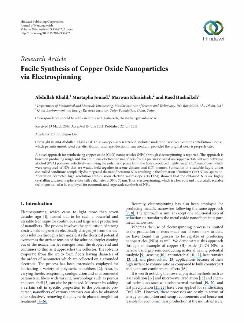
Figure 1: SEM image of as-spun composite nanofibers with highlydefective morphology. Broken junctions and beads are marked withdotted circle and arrow, respectively.
polymer removal will also be affected by the solution flowrate and the voltage employed during the electrospinning.If the values of these two parameters are such that poorbalance is maintained between solution delivery and solutionremoval from the needle end, not only the morphologyof as-spun composite fibers becomes highly defective, butalso the morphology of calcined nanofibers becomes verydefective and nonuniform. In our case, 0.2mL/hr-20 kV and0.5mL/hr-29 kV were found to be the optimized sets of flowrates and voltages for producing uniform and continuousnanofibers. If one of the parameters in these sets is inter-changed, the result is highly discontinuous and nonuniformfibers due to imbalance between electrostatic and viscoelasticforces. Figure 1 shows the SEM image of as-spun compositenanofibers obtained at 0.2mL/hr-29 kV. The nanofibers arecharacterized by pronounced breaking and beading whichwere expected due to unstable jet formation during electro-spinning. Similar morphology was observed for 0.5mL/hr-20 kV.
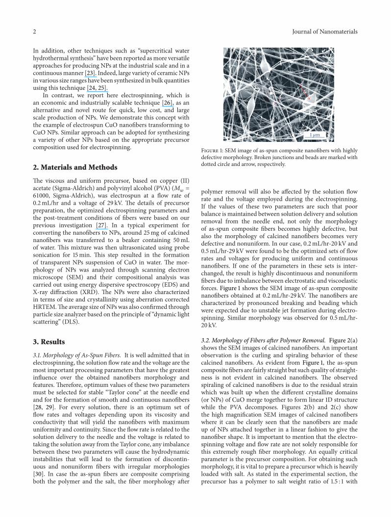
3.2. Morphology of Fibers after Polymer Removal. Figure 2(a)shows the SEM images of calcined nanofibers. An importantobservation is the curling and spiraling behavior of thesecalcined nanofibers. As evident from Figure 1, the as-spuncomposite fibers are fairly straight but such quality of straight-ness is not evident in calcined nanofibers. The observedspiraling of calcined nanofibers is due to the residual strainwhich was built up when the different crystalline domains(or NPs) of CuO merge together to form linear 1D structurewhile the PVA decomposes. Figures 2(b) and 2(c) showthe high magnification SEM images of calcined nanofiberswhere it can be clearly seen that the nanofibers are madeup of NPs attached together in a linear fashion to give thenanofiber shape. It is important to mention that the electro-spinning voltage and flow rate are not solely responsible forthis extremely rough fiber morphology. An equally criticalparameter is the precursor composition. For obtaining suchmorphology, it is vital to prepare a precursor which is heavilyloaded with salt. As stated in the experimental section, theprecursor has a polymer to salt weight ratio of 1.5 : 1 with
Journal of Nanomaterials 3
Cu LO K
2𝜇m 1𝜇m
100nm
Cou
nts
15k
12k
9k
6k
3k
0
30 40 50 60 70
(110
)
(002
)
(200
)
(202
)
(020
)
(202
)
(113
)
(311
)(220
)
(e)
EDS quantitative results
Element (Wt%) (At%)OK 19.34 48.77CuL 80.66 51.23
Cou
nts
1500
1000
500
2000
0 4321(KeV)
(Err%)1.872.64
(f)
(a) (b) (c)
(d)
2𝜃 (deg)
100nm
Figure 2: (a) SEM image of CuO nanofibers obtained after calcination. ((b) and (c)) Magnified images of (a). (d) Nanofibers changing toNPs’ clusters after sonication in water. (e) XRD spectrum of CuO NPs. (f) EDS spectrum and quantitative results of CuO NPs (the longestpeak in EDS spectrum corresponds to Si, which was used as a substrate for collecting nanofibers and its contribution was excluded from thequantitative results).
only 1mL additional water. The available water from thepolymer solution and this separately added 1mLwater are farbelow the minimum amount required for forming clear andsaturatedCuAc aqueous solution.Thus, the precursor formedis basically a sol-gel comprised of CuAc particles uniformlydistributed across the solution. Such high loading of saltcauses dense confinement of salt across the nanofiber whichultimately results in the formation of CuO NPs connectedtogether in linear 1D pattern. The XRD spectrum withindexed peaks, shown in Figure 2(e), confirms the purityand crystallinity of CuO NPs [31]. The EDS spectra and thequantitative results for NPs, shown in Figure 2(f), match wellwith the stoichiometric ratio of Cu and O in pure CuO,
conforming to the fact that the obtained NPs are nearly pureCuO.
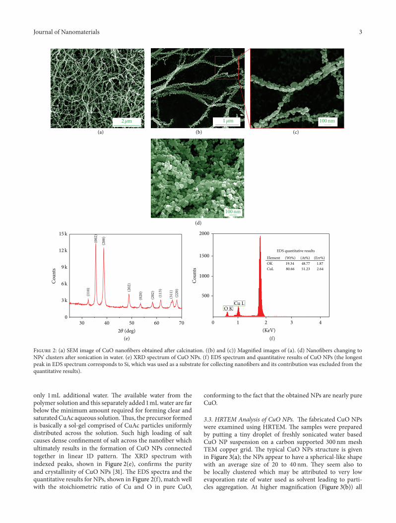
3.3. HRTEM Analysis of CuO NPs. The fabricated CuO NPswere examined using HRTEM. The samples were preparedby putting a tiny droplet of freshly sonicated water basedCuO NP suspension on a carbon supported 300 nm meshTEM copper grid. The typical CuO NPs structure is givenin Figure 3(a); the NPs appear to have a spherical-like shapewith an average size of 20 to 40 nm. They seem also tobe locally clustered which may be attributed to very lowevaporation rate of water used as solvent leading to parti-cles aggregation. At higher magnification (Figure 3(b)) all
4 Journal of Nanomaterials
50nm
(a)
5nm
(b)
5nm
(c)
2.9A
(d)
[111]
[111]
[202]
(e)
Figure 3: (a) TEM image of clusteredCuONPs. (b)HRTEM image of CuONP showing high degree of crystallinity with randomorientations.(c) HRTEM examination of single CuO NP. (d) Zoom-in view of crystal showing well aligned atomic planes with 2.9 A spacing. (e) FFT ofthe image shown in (c) matching the [101] zone axis for the monoclinic structure.
PD < 0.01 0.1 < PD < 0.50.01 < PD < 0.1
30
–40
40
–50
50
–60
60
–70
70
–80
80
–90
90
–100
100
–150
150
–200
200
–250
250
–300
300
–400
400
–500
500
–600
600
–700
050
100150200250300
Cou
nts
Particle size range (nm)
(a)
Run number1 39.8 0.0222 30.5 0.0053 50.1 0.0734 240.5 0.1695 323.5 0.1946 460.9 0.2737 514.4 0.2998 571.9 0.3179 529.2 0.311
10 657.4 0.412
Size (nm) Polydispersity Zeta potential (mV)−10.91−13.88−19.45−20.99−24.43−18.35−25.03−21.98−29.34−26.38
(b)
Figure 4: (a) CuO NPs size distribution and (b) typical example of a test consisting of 10 runs conducted for estimating CuO NP size.
observed CuO NPs exhibit atomic fringes with a specificorientation. This is clear evidence that the synthetized CuONPs are all single crystals with random orientations. FurtherHRTEM examination of single CuO NP is presented inFigure 3(c): this NP structure was highlighted through (101)zone axis given in fast Fourier transformed (FFT) image inFigure 3(e). The atomic columns of this nanocrystal seem to
be lying along [1 1 1] direction. The zoom in view of thisNP structure is given in Figure 3(d) which allows measuringthe interplanar spacing of 𝑑 = 2.9 A. Further analysis of theFFT data allows determining the lattice parameters of thisnanocrystal through the indexation of all visible spots andthe angles between different orientations. Our measurementgives these values (𝑎 = 4.12 A) and (𝛼 = 𝛾 = 89∘; 𝛽 = 100∘).
Journal of Nanomaterials 5
This result is in good agreement with the crystal structure ofmonoclinic CuO as given in the literature (𝑎 = 4.6837 A,𝑏 = 3.4226 A, and 𝑐 = 5.1288 A) and (𝛼 = 𝛾 = 90∘,𝛽 = 99.54
∘).
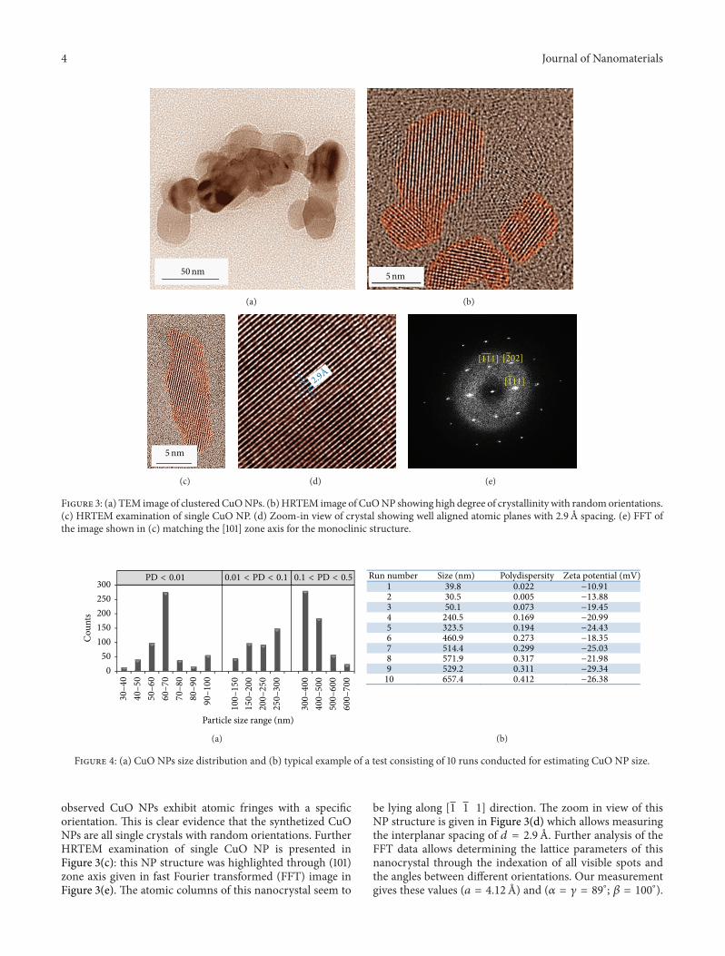
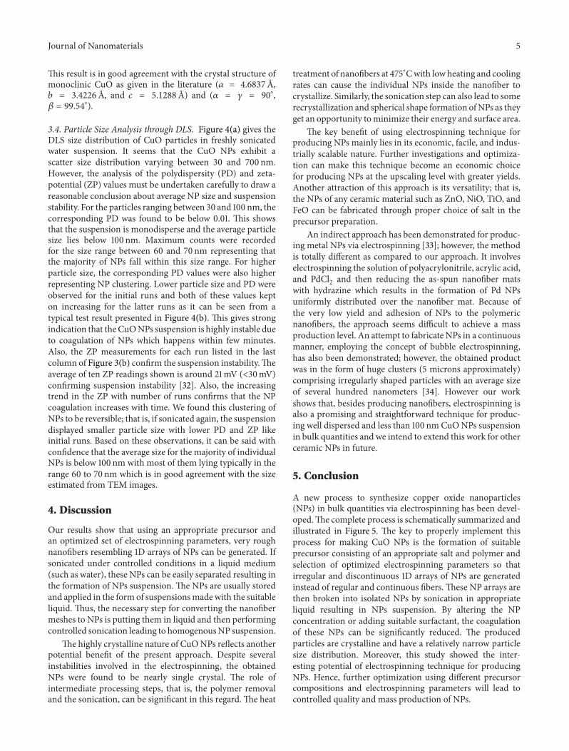
3.4. Particle Size Analysis through DLS. Figure 4(a) gives theDLS size distribution of CuO particles in freshly sonicatedwater suspension. It seems that the CuO NPs exhibit ascatter size distribution varying between 30 and 700 nm.However, the analysis of the polydispersity (PD) and zeta-potential (ZP) values must be undertaken carefully to draw areasonable conclusion about average NP size and suspensionstability. For the particles ranging between 30 and 100 nm, thecorresponding PD was found to be below 0.01. This showsthat the suspension is monodisperse and the average particlesize lies below 100 nm. Maximum counts were recordedfor the size range between 60 and 70 nm representing thatthe majority of NPs fall within this size range. For higherparticle size, the corresponding PD values were also higherrepresenting NP clustering. Lower particle size and PD wereobserved for the initial runs and both of these values kepton increasing for the latter runs as it can be seen from atypical test result presented in Figure 4(b). This gives strongindication that theCuONPs suspension is highly instable dueto coagulation of NPs which happens within few minutes.Also, the ZP measurements for each run listed in the lastcolumn of Figure 3(b) confirm the suspension instability.Theaverage of ten ZP readings shown is around 21mV (<30mV)confirming suspension instability [32]. Also, the increasingtrend in the ZP with number of runs confirms that the NPcoagulation increases with time. We found this clustering ofNPs to be reversible; that is, if sonicated again, the suspensiondisplayed smaller particle size with lower PD and ZP likeinitial runs. Based on these observations, it can be said withconfidence that the average size for the majority of individualNPs is below 100 nm with most of them lying typically in therange 60 to 70 nm which is in good agreement with the sizeestimated from TEM images.
4. Discussion
Our results show that using an appropriate precursor andan optimized set of electrospinning parameters, very roughnanofibers resembling 1D arrays of NPs can be generated. Ifsonicated under controlled conditions in a liquid medium(such as water), these NPs can be easily separated resulting inthe formation of NPs suspension. The NPs are usually storedand applied in the formof suspensionsmadewith the suitableliquid. Thus, the necessary step for converting the nanofibermeshes to NPs is putting them in liquid and then performingcontrolled sonication leading to homogenousNP suspension.
The highly crystalline nature of CuONPs reflects anotherpotential benefit of the present approach. Despite severalinstabilities involved in the electrospinning, the obtainedNPs were found to be nearly single crystal. The role ofintermediate processing steps, that is, the polymer removaland the sonication, can be significant in this regard. The heat
treatment of nanofibers at 475∘Cwith lowheating and coolingrates can cause the individual NPs inside the nanofiber tocrystallize. Similarly, the sonication step can also lead to somerecrystallization and spherical shape formation ofNPs as theyget an opportunity tominimize their energy and surface area.
The key benefit of using electrospinning technique forproducing NPs mainly lies in its economic, facile, and indus-trially scalable nature. Further investigations and optimiza-tion can make this technique become an economic choicefor producing NPs at the upscaling level with greater yields.Another attraction of this approach is its versatility; that is,the NPs of any ceramic material such as ZnO, NiO, TiO, andFeO can be fabricated through proper choice of salt in theprecursor preparation.
An indirect approach has been demonstrated for produc-ing metal NPs via electrospinning [33]; however, the methodis totally different as compared to our approach. It involveselectrospinning the solution of polyacrylonitrile, acrylic acid,and PdCl
2and then reducing the as-spun nanofiber mats
with hydrazine which results in the formation of Pd NPsuniformly distributed over the nanofiber mat. Because ofthe very low yield and adhesion of NPs to the polymericnanofibers, the approach seems difficult to achieve a massproduction level. An attempt to fabricate NPs in a continuousmanner, employing the concept of bubble electrospinning,has also been demonstrated; however, the obtained productwas in the form of huge clusters (5 microns approximately)comprising irregularly shaped particles with an average sizeof several hundred nanometers [34]. However our workshows that, besides producing nanofibers, electrospinning isalso a promising and straightforward technique for produc-ing well dispersed and less than 100 nm CuONPs suspensionin bulk quantities and we intend to extend this work for otherceramic NPs in future.
5. Conclusion
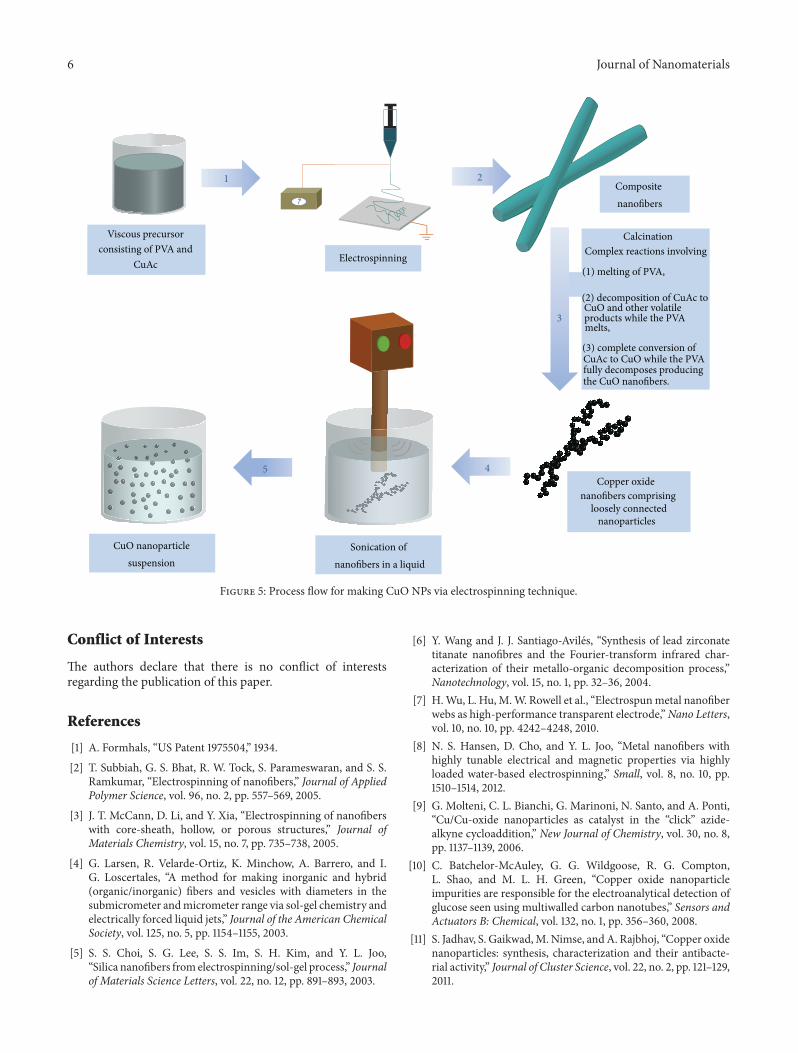
A new process to synthesize copper oxide nanoparticles(NPs) in bulk quantities via electrospinning has been devel-oped.The complete process is schematically summarized andillustrated in Figure 5. The key to properly implement thisprocess for making CuO NPs is the formation of suitableprecursor consisting of an appropriate salt and polymer andselection of optimized electrospinning parameters so thatirregular and discontinuous 1D arrays of NPs are generatedinstead of regular and continuous fibers. These NP arrays arethen broken into isolated NPs by sonication in appropriateliquid resulting in NPs suspension. By altering the NPconcentration or adding suitable surfactant, the coagulationof these NPs can be significantly reduced. The producedparticles are crystalline and have a relatively narrow particlesize distribution. Moreover, this study showed the inter-esting potential of electrospinning technique for producingNPs. Hence, further optimization using different precursorcompositions and electrospinning parameters will lead tocontrolled quality and mass production of NPs.
6 Journal of Nanomaterials
Electrospinning
Calcination
Composite nanofibers
Copper oxide nanofibers comprising
loosely connected nanoparticles
Sonication of nanofibers in a liquid
CuO nanoparticlesuspension
1 2
3
45
Complex reactions involving Viscous precursor
consisting of PVA andCuAc (1) melting of PVA,
(3) complete conversion ofCuAc to CuO while the PVAfully decomposes producingthe CuO nanofibers.
(2) decomposition of CuAc toCuO and other volatileproducts while the PVAmelts,
Figure 5: Process flow for making CuO NPs via electrospinning technique.
Conflict of Interests
The authors declare that there is no conflict of interestsregarding the publication of this paper.
References
[1] A. Formhals, “US Patent 1975504,” 1934.[2] T. Subbiah, G. S. Bhat, R. W. Tock, S. Parameswaran, and S. S.
Ramkumar, “Electrospinning of nanofibers,” Journal of AppliedPolymer Science, vol. 96, no. 2, pp. 557–569, 2005.
[3] J. T. McCann, D. Li, and Y. Xia, “Electrospinning of nanofiberswith core-sheath, hollow, or porous structures,” Journal ofMaterials Chemistry, vol. 15, no. 7, pp. 735–738, 2005.
[4] G. Larsen, R. Velarde-Ortiz, K. Minchow, A. Barrero, and I.G. Loscertales, “A method for making inorganic and hybrid(organic/inorganic) fibers and vesicles with diameters in thesubmicrometer andmicrometer range via sol-gel chemistry andelectrically forced liquid jets,” Journal of the American ChemicalSociety, vol. 125, no. 5, pp. 1154–1155, 2003.
[5] S. S. Choi, S. G. Lee, S. S. Im, S. H. Kim, and Y. L. Joo,“Silica nanofibers fromelectrospinning/sol-gel process,” Journalof Materials Science Letters, vol. 22, no. 12, pp. 891–893, 2003.
[6] Y. Wang and J. J. Santiago-Aviles, “Synthesis of lead zirconatetitanate nanofibres and the Fourier-transform infrared char-acterization of their metallo-organic decomposition process,”Nanotechnology, vol. 15, no. 1, pp. 32–36, 2004.
[7] H.Wu, L. Hu,M.W. Rowell et al., “Electrospunmetal nanofiberwebs as high-performance transparent electrode,”Nano Letters,vol. 10, no. 10, pp. 4242–4248, 2010.
[8] N. S. Hansen, D. Cho, and Y. L. Joo, “Metal nanofibers withhighly tunable electrical and magnetic properties via highlyloaded water-based electrospinning,” Small, vol. 8, no. 10, pp.1510–1514, 2012.
[9] G. Molteni, C. L. Bianchi, G. Marinoni, N. Santo, and A. Ponti,“Cu/Cu-oxide nanoparticles as catalyst in the “click” azide-alkyne cycloaddition,” New Journal of Chemistry, vol. 30, no. 8,pp. 1137–1139, 2006.
[10] C. Batchelor-McAuley, G. G. Wildgoose, R. G. Compton,L. Shao, and M. L. H. Green, “Copper oxide nanoparticleimpurities are responsible for the electroanalytical detection ofglucose seen using multiwalled carbon nanotubes,” Sensors andActuators B: Chemical, vol. 132, no. 1, pp. 356–360, 2008.
[11] S. Jadhav, S. Gaikwad,M.Nimse, andA. Rajbhoj, “Copper oxidenanoparticles: synthesis, characterization and their antibacte-rial activity,” Journal of Cluster Science, vol. 22, no. 2, pp. 121–129,2011.
Journal of Nanomaterials 7
[12] G. Ren, D. Hu, E. W. C. Cheng, M. A. Vargas-Reus, P. Reip, andR. P. Allaker, “Characterisation of copper oxide nanoparticlesfor antimicrobial applications,” International Journal of Antimi-crobial Agents, vol. 33, no. 6, pp. 587–590, 2009.
[13] M. H. Chang, H. S. Liu, and C. Y. Tai, “Preparation of copperoxide nanoparticles and its application in nanofluid,” PowderTechnology, vol. 207, no. 1–3, pp. 378–386, 2011.
[14] S. Asthana, S. Rattan, and M. Das, “Comparative studies ofcopper oxide with aluminium oxide nanoparticles in conven-tional thermal fluids for its enhanced efficiency as coolant,”Proceedings of the National Academy of Sciences, India A:Physical Sciences, vol. 83, no. 2, pp. 73–77, 2013.
[15] H. Kidowaki, T. Oku, T. Akiyama, A. Suzuki, B. Jeyadevan, andJ. Cuya, “Fabrication and characterization of CuO-based solarcells,” Journal of Materials Science Research, vol. 1, no. 1, pp. 138–143, 2012.
[16] K. Borgohain, J. B. Singh, M. V. R. Rao, T. Shripathi, andS. Mahamuni, “Quantum size effects in CuO nanoparticles,”Physical Review B, vol. 61, no. 16, pp. 11093–11096, 2000.
[17] K. Suzuki, N. Tanaka, A. Ando, and H. Takagi, “Size-selectedcopper oxide nanoparticles synthesized by laser ablation,” Jour-nal of Nanoparticle Research, vol. 14, no. 5, article 0863, 2012.
[18] H. Wang, J. Z. Xu, J. J. Zhu, and H. Y. Chen, “Preparation ofCuOnanoparticles bymicrowave irradiation,” Journal of CrystalGrowth, vol. 244, no. 1, pp. 88–94, 2002.
[19] Z. Hong, Y. Cao, and J. Deng, “A convenient alcohothermalapproach for low temperature synthesis of CuO nanoparticles,”Materials Letters, vol. 52, no. 1-2, pp. 34–38, 2002.
[20] T. Kida, T. Oka, M. Nagano, Y. Ishiwata, and X.-G. Zheng,“Synthesis and application of stable copper oxide nanoparticlesuspensions for nanoparticulate film fabrication,” Journal of theAmerican Ceramic Society, vol. 90, no. 1, pp. 107–110, 2007.
[21] J. Zhu, D. Li, H. Chen, X. Yang, L. Lu, and X. Wang, “Highlydispersed CuO nanoparticles prepared by a novel quick-precipitation method,” Materials Letters, vol. 58, no. 26, pp.3324–3327, 2004.
[22] A. S. Lanje, S. J. Sharma, R. B. Pode, and R. S. Ningthou-jam, “Synthesis and optical characterization of copper oxidenanoparticles,” Advances in Applied Science Research, vol. 1, no.2, pp. 36–40, 2010.
[23] E. Lester, P. Blood, J. Denyer, D. Giddings, B. Azzopardi, andM. Poliakoff, “Reaction engineering: The supercritical waterhydrothermal synthesis of nano-particles,” Journal of Supercrit-ical Fluids, vol. 37, no. 2, pp. 209–214, 2006.
[24] A. Cabanas, J. Li, P. Blood et al., “Synthesis of nanoparticulateyttrium aluminum garnet in supercritical water-ethanol mix-tures,” Journal of Supercritical Fluids, vol. 40, no. 2, pp. 284–292,2007.
[25] C. J. Tighe, R. Q. Cabrera, R. I. Gruar, and J. A. Darr,“Scale up production of nanoparticles: continuous supercriticalwater synthesis of Ce-Zn oxides,” Industrial and EngineeringChemistry Research, vol. 52, no. 16, pp. 5522–5528, 2013.
[26] W. Sigmund, J. Yuh, H. Park et al., “Processing and structurerelationships in electrospinning of ceramic fiber systems,”Journal of the American Ceramic Society, vol. 89, no. 2, pp. 395–407, 2006.
[27] A. Khalil, R. Hashaikeh, and M. Jouiad, “Synthesis and mor-phology analysis of electrospun copper nanowires,” Journal ofMaterials Science, vol. 49, pp. 3052–3065, 2014.
[28] J. M. Deitzel, J. Kleinmeyer, D. Harris, and N. C. Beck Tan, “Theeffect of processing variables on the morphology of electrospun
nanofibers and textiles,” Polymer, vol. 42, no. 1, pp. 261–272,2001.
[29] S. Megelski, J. S. Stephens, D. Bruce Chase, and J. F. Rabolt,“Micro- and nanostructured surface morphology on electro-spun polymer fibers,”Macromolecules, vol. 35, no. 22, pp. 8456–8466, 2002.
[30] M. M. Hohman, M. Shin, G. Rutledge, and M. P. Brenner,“Electrospinning and electrically forced jets. I. Stability theory,”Physics of Fluids, vol. 13, no. 8, pp. 2201–2220, 2001.
[31] “JCPDS card no. 05-0661,” 1986.[32] R. Greenwood andK. Kendall, “Selection of suitable dispersants
for aqueous suspensions of zirconia and titania powders usingacoustophoresis,” Journal of the European Ceramic Society, vol.19, no. 4, pp. 479–488, 1999.
[33] M.M. Demir, M. A. Gulgun, Y. Z. Menceloglu et al., “Palladiumnanoparticles by electrospinning from poly(acrylonitrile-co-acrylic acid)-PdCl2 solutions: relations between preparationconditions, particle size, and catalytic activity,”Macromolecules,vol. 37, no. 5, pp. 1787–1792, 2004.
[34] H. Dou and J. H. He, “Nanoparticles fabricated by the bubbleelectrospinning,”Thermal Science, vol. 16, no. 5, pp. 1562–1563,2012.

Submit your manuscripts athttp://www.hindawi.com
ScientificaHindawi Publishing Corporationhttp://www.hindawi.com Volume 2014
CorrosionInternational Journal of
Hindawi Publishing Corporationhttp://www.hindawi.com Volume 2014
Hindawi Publishing Corporationhttp://www.hindawi.com Volume 2014
Polymer ScienceInternational Journal of
Hindawi Publishing Corporationhttp://www.hindawi.com Volume 2014
CeramicsJournal of
Hindawi Publishing Corporationhttp://www.hindawi.com Volume 2014
CompositesJournal of
NanoparticlesJournal of
Hindawi Publishing Corporationhttp://www.hindawi.com Volume 2014
Hindawi Publishing Corporationhttp://www.hindawi.com Volume 2014
International Journal of
Biomaterials
Hindawi Publishing Corporationhttp://www.hindawi.com Volume 2014
NanoscienceJournal of
TextilesHindawi Publishing Corporation http://www.hindawi.com Volume 2014
Journal of
NanotechnologyHindawi Publishing Corporationhttp://www.hindawi.com Volume 2014
Journal of
Hindawi Publishing Corporationhttp://www.hindawi.com
Volume 2014
CrystallographyJournal of
The Scientific World JournalHindawi Publishing Corporation http://www.hindawi.com Volume 2014
Hindawi Publishing Corporationhttp://www.hindawi.com Volume 2014
CoatingsJournal of
Advances in
Materials Science and EngineeringHindawi Publishing Corporationhttp://www.hindawi.com Volume 2014
Smart Materials Research
Hindawi Publishing Corporationhttp://www.hindawi.com Volume 2014
Hindawi Publishing Corporationhttp://www.hindawi.com Volume 2014
MetallurgyJournal of
Hindawi Publishing Corporationhttp://www.hindawi.com Volume 2014
BioMed Research International
Hindawi Publishing Corporationhttp://www.hindawi.com
Volume 2014
MaterialsJournal of
Nano
materials
Hindawi Publishing Corporationhttp://www.hindawi.com Volume 2014
Journal ofNanomaterials


![Synthesis of CuO nanoparticles for catalytic … 35 06.pdfProcessing and Applicationof Ceramics 11 [1] (2017)39–44 DOI: 10.2298/PAC1701039Y Synthesis of CuO nanoparticles for catalytic](https://img.dokumen.tips/doc/110x75/5e94d01ffcf72854d647ed4f/synthesis-of-cuo-nanoparticles-for-catalytic-35-06pdf-processing-and-applicationof.jpg)

![International Journal of Engineeringlubricating oil in order to remove heat from high heat flux surfaces [16, 17]. Also, to study the behavior of CuO nanoparticles more effectively,](https://img.dokumen.tips/doc/110x75/609f2e8902f91d1a353fd099/international-journal-of-lubricating-oil-in-order-to-remove-heat-from-high-heat.jpg)