Embed Size (px)
Citation preview
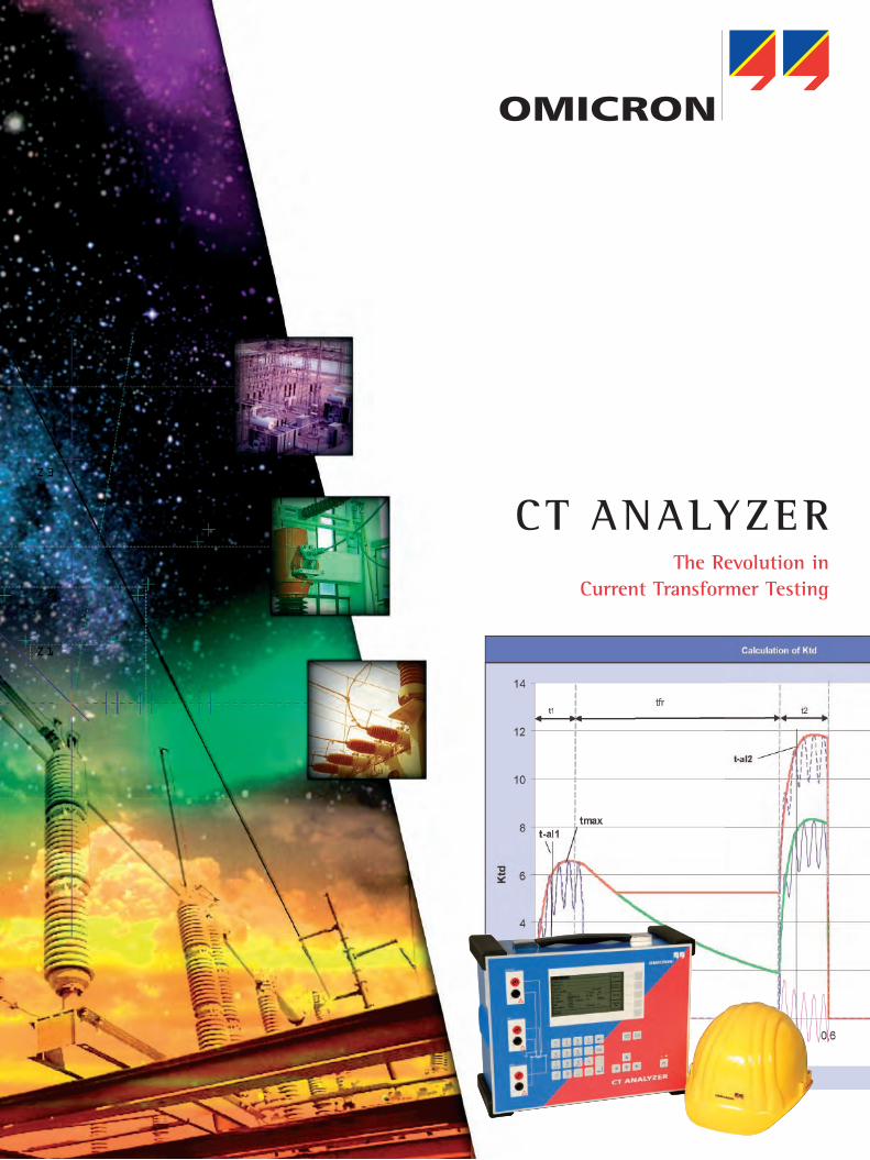
CT ANALYZERThe Revolution in
Current Transformer Testing
2
The Unique Solution
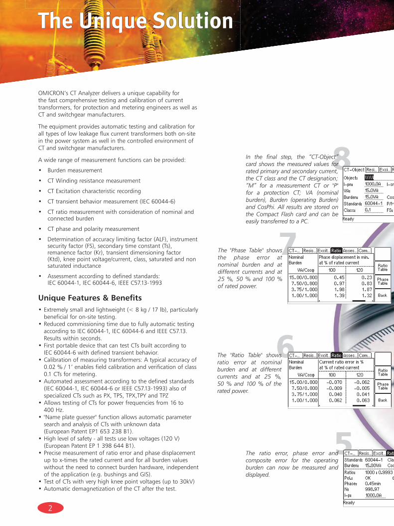
OMICRON’s CT Analyzer delivers a unique capability for the fast comprehensive testing and calibration of current transformers, for protection and metering engineers as well as CT and switchgear manufacturers.
The equipment provides automatic testing and calibration for all types of low leakage flux current transformers both on-site in the power system as well in the controlled environment of CT and switchgear manufacturers.
A wide range of measurement functions can be provided:
• Burdenmeasurement
• CTWindingresistancemeasurement
• CTExcitationcharacteristicrecording
• CTtransientbehaviormeasurement(IEC60044-6)
• CTratiomeasurementwithconsiderationofnominaland connected burden
• CTphaseandpolaritymeasurement
• Determinationofaccuracylimitingfactor(ALF),instrumentsecurityfactor(FS),secondarytimeconstant(Ts),remanencefactor(Kr),transientdimensioningfactor(Ktd),kneepointvoltage/current,class,saturatedandnonsaturated inductance
• Assessmentaccordingtodefinedstandards: IEC60044-1,IEC60044-6,IEEEC57.13-1993
Unique Features & Benefits•Extremelysmallandlightweight(<8kg/17lb),particularly
beneficial for on-site testing.•Reduced commissioning time due to fully automatic testing accordingtoIEC60044-1,IEC60044-6andIEEEC57.13.Results within seconds.
•FirstportabledevicethatcantestCTsbuiltaccordingto IEC60044-6withdefinedtransientbehavior.
•Calibrationofmeasuringtransformers:Atypicalaccuracyof0.02%/1’enablesfieldcalibrationandverificationofclass0.1CTsformetering.
•Automatedassessmentaccordingtothedefinedstandards(IEC60044-1,IEC60044-6orIEEEC57.13-1993)alsoofspecializedCTssuchasPX,TPS,TPX,TPYandTPZ
•AllowstestingofCTsforpowerfrequenciesfrom16to 400Hz.
•"Nameplateguesser"functionallowsautomaticparametersearch and analysis of CTs with unknown data (EuropeanPatentEP1653238B1).
•Highlevelofsafety-alltestsuselowvoltages(120V) (EuropeanPatentEP1398644B1).•Precisemeasurementofratioerrorandphasedisplacement
up to x-times the rated current and for all burden values without the need to connect burden hardware, independent oftheapplication(e.g.bushingsandGIS).
•TestofCTswithveryhighkneepointvoltages(upto30kV)•AutomaticdemagnetizationoftheCTafterthetest.
5
6
7
8In the final step, the “CT-Object” card shows the measured values for rated primary and secondary current, the CT class and the CT designation; “M” for a measurement CT or "P" for a protection CT; VA (nominal burden), Burden (operating Burden) and CosPhi. All results are stored on the Compact Flash card and can be easily transferred to a PC.
The ratio error, phase error and composite error for the operating burden can now be measured and displayed.
The "Ratio Table" shows ratio error at nominal burden and at different currents and at 25 %, 50 % and 100 % of the rated power.
The "Phase Table" shows the phase error at nominal burden and at different currents and at 25 %, 50 % and 100 % of rated power.
3
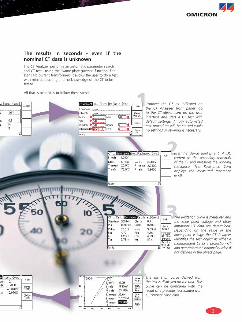
The results in seconds - even if the nominal CT data is unknownThe CT Analyzer performs an automatic parameter search andCTtest-usingthe"Nameplateguesser"function.Forstandard current transformers it allows the user to do a test with minimal training and no knowledge of the CT to be tested.
All that is needed is to follow these steps:
2
1
3
4
Connect the CT as indicated on the CT Analyzer front panel, go to the CT-object card on the user interface and start a CT test with default settings. A fully automated test procedure will be started while no settings or rewiring is necessary.
First the device applies a 1 A DC current to the secondary terminals of the CT and measures the winding resistance. The Resistance Card displays the measured resistance (R ct).
The excitation curve is measured and the knee point voltage and other important CT data are determined. Depending on the value of the knee point voltage the CT Analyzer identifies the test object as either a measurement CT or a protection CT and determines the nominal burden if not defined in the object page.
The excitation curve derived from the test is displayed on the unit. This curve can be compared with the result of a previous test loaded from a Compact Flash card.
4
CT Analyzer Functionality
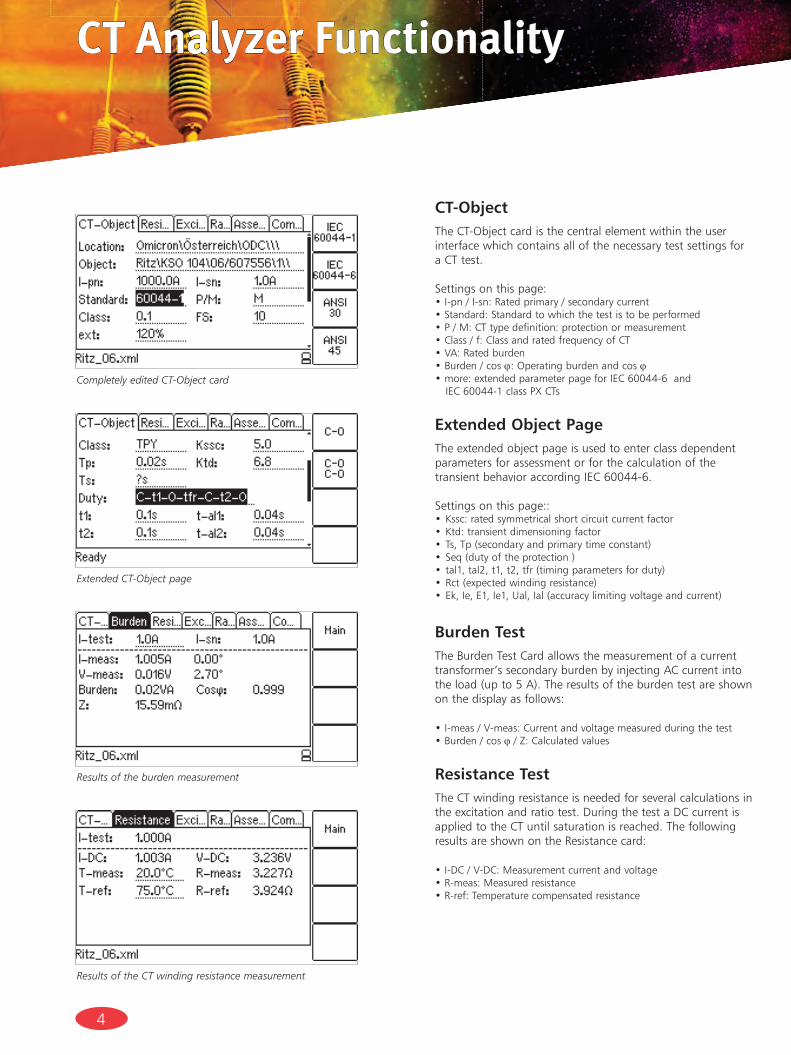
CT-Object The CT-Object card is the central element within the user interface which contains all of the necessary test settings for a CT test.
Settingsonthispage:•I-pn/I-sn:Ratedprimary/secondarycurrent•Standard:Standardtowhichthetestistobeperformed•P/M:CTtypedefinition:protectionormeasurement•Class/f:ClassandratedfrequencyofCT•VA:Ratedburden•Burden/cosϕ: Operating burden and cos ϕ•more:extendedparameterpageforIEC60044-6and IEC60044-1classPXCTs
Extended Object Page The extended object page is used to enter class dependent parameters for assessment or for the calculation of the transientbehavioraccordingIEC60044-6.
Settingsonthispage::Kssc:ratedsymmetricalshortcircuitcurrentfactor•Ktd:transientdimensioningfactor•Ts,Tp(secondaryandprimarytimeconstant)•Seq(dutyoftheprotection)•tal1,tal2,t1,t2,tfr(timingparametersforduty)•Rct(expectedwindingresistance)•Ek,Ie,E1,Ie1,Ual,Ial(accuracylimitingvoltageandcurrent)•
Burden TestTheBurdenTestCardallowsthemeasurementofacurrenttransformer’s secondary burden by injecting AC current into theload(upto5A).Theresultsoftheburdentestareshownon the display as follows:
•I-meas/V-meas:Currentandvoltagemeasuredduringthetest•Burden/cosϕ /Z:Calculatedvalues
Resistance TestThe CT winding resistance is needed for several calculations intheexcitationandratiotest.DuringthetestaDCcurrentisapplied to the CT until saturation is reached. The following results are shown on the Resistance card:
•I-DC/V-DC:Measurementcurrentandvoltage•R-meas:Measuredresistance•R-ref:Temperaturecompensatedresistance
Completely edited CT-Object card
Results of the CT winding resistance measurement
Results of the burden measurement
Extended CT-Object page
5
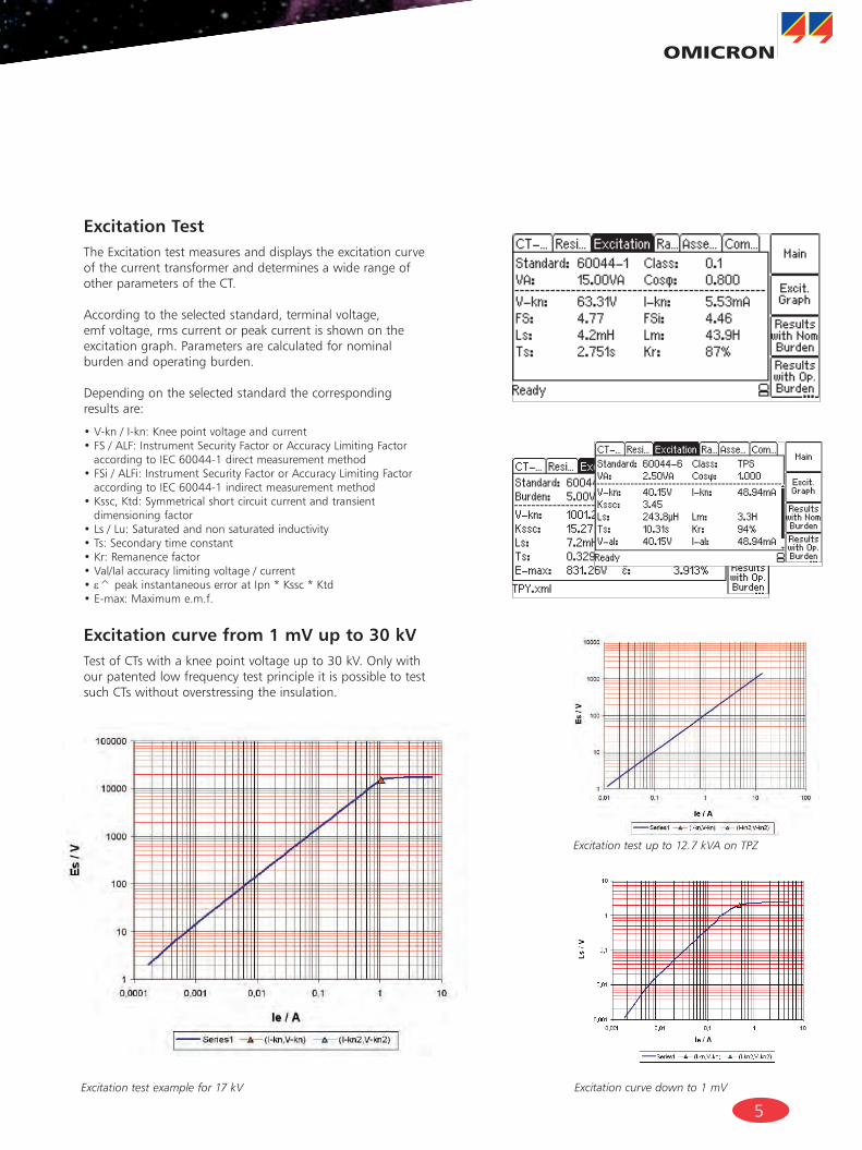
Excitation TestTheExcitationtestmeasuresanddisplaystheexcitationcurveof the current transformer and determines a wide range of other parameters of the CT.
According to the selected standard, terminal voltage, emf voltage, rms current or peak current is shown on the excitation graph. Parameters are calculated for nominal burden and operating burden.
Dependingontheselectedstandardthecorrespondingresults are:
•V-kn/I-kn:Kneepointvoltageandcurrent•FS/ALF:InstrumentSecurityFactororAccuracyLimitingFactoraccordingtoIEC60044-1directmeasurementmethod
•FSi/ALFi:InstrumentSecurityFactororAccuracyLimitingFactoraccordingtoIEC60044-1indirectmeasurementmethod
•Kssc,Ktd:Symmetricalshortcircuitcurrentandtransientdimensioning factor
•Ls/Lu:Saturatedandnonsaturatedinductivity•Ts:Secondarytimeconstant•Kr:Remanencefactor•Val/Ialaccuracylimitingvoltage/current•ε^peakinstantaneouserroratIpn*Kssc*Ktd•E-max:Maximume.m.f.
Excitation curve from 1 mV up to 30 kVTestofCTswithakneepointvoltageupto30kV.Onlywithour patented low frequency test principle it is possible to test such CTs without overstressing the insulation.
Excitation test example for 17 kV
Excitation test up to 12.7 kVA on TPZ
Excitation curve down to 1 mV
6
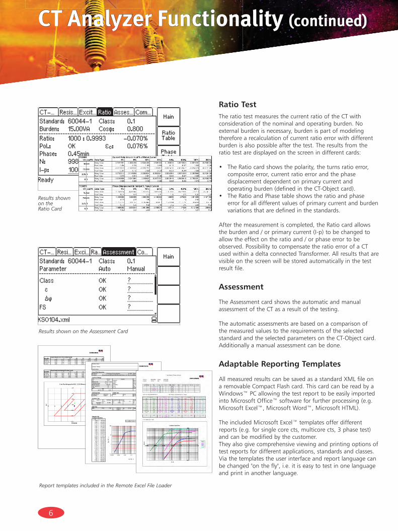
Ratio TestThe ratio test measures the current ratio of the CT with consideration of the nominal and operating burden. No external burden is necessary, burden is part of modeling therefore a recalculation of current ratio error with different burden is also possible after the test. The results from the ratio test are displayed on the screen in different cards:
• TheRatiocardshowsthepolarity,theturnsratioerror,composite error, current ratio error and the phase displacement dependent on primary current and operatingburden(definedintheCT-Objectcard).
• TheRatioandPhasetableshowstheratioandphaseerror for all different values of primary current and burden variations that are defined in the standards.
After the measurement is completed, the Ratio card allowstheburdenand/orprimarycurrent(I-p)tobechangedtoallowtheeffectontheratioand/orphaseerrortobeobserved. Possibility to compensate the ratio error of a CTused within a delta connected Transformer. All results that are visible on the screen will be stored automatically in the test result file.
Assessment
The Assessment card shows the automatic and manual assessment of the CT as a result of the testing.
The automatic assessments are based on a comparison of the measured values to the requirements of the selected standard and the selected parameters on the CT-Object card. Additionally a manual assessment can be done.
Adaptable Reporting Templates
AllmeasuredresultscanbesavedasastandardXMLfileonaremovableCompactFlashcard.ThiscardcanbereadbyaWindows™PCallowingthetestreporttobeeasilyimportedintoMicrosoftOffice™softwareforfurtherprocessing(e.g.MicrosoftExcel™,MicrosoftWord™,MicrosoftHTML).
TheincludedMicrosoftExcel™templatesofferdifferentreports(e.g.forsinglecorects,multicorects,3phasetest)and can be modified by the customer.They also give comprehensive viewing and printing options of test reports for different applications, standards and classes. Viathetemplatestheuserinterfaceandreportlanguagecanbechanged"onthefly",i.e.itiseasytotestinonelanguageand print in another language.
Results shown on the Assessment Card
Results shownon the Ratio Card
Report templates included in the Remote Excel File Loader
CT Analyzer Functionality (continued)
7
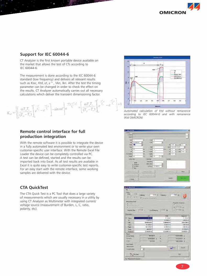
Support for IEC 60044-6CT Analyzer is the first known portable device available on the market that allows the test of CTs according to IEC60044-6.
ThemeasurementisdoneaccordingtotheIEC60044-6standard(lowfrequency)anddeliversallrelevantresultssuchasKssc,Ktd,εt, ε^,Vkn,Ikn.Afterthetestthetimingparameter can be changed in order to check the effect on the results. CT Analyzer automatically carries out all necessary calculations which deliver the transient dimensioning factor.
Remote control interface for full production integrationWiththeremotesoftwareitispossibletointegratethedevicein a fully automated test environment or to write your own customer-specificuserinterface.WiththeRemoteExcelFileLoaderthedevicecanbecompletelycontrolledviaPC.A test can be defined, started and the results can be importedbackintoExcel.AsalltestresultsareavailableinExcelitisquiteeasytowritecustomer-specifictestreports.Foraneasystartwiththeremoteinterface,someworkingsamples are delivered with the device.
CTA QuickTestThe CTA Quick Test is a PC Tool that does a large variety of measurements which are usually necessary in a utility by usingCTAnalyzerasMultimeterwithintegratedcurrent/voltagesource(measurementofBurden,L,C,ratio,polarity,etc).
Automated calculation of Ktd without remanence according to IEC 60044-6 and with remanence (Ktd OMICRON)
CT Analyzer Functionality (continued)
8
Netsim Support
TheCTAtoNETSIMexportToolallowstoimporttheCTdatafromaCTAnalyzertestreportintotheTestUniversenetworksimulationsoftwareNetSimtousethemeasureddatafornetwork simulation.
Calibration
Atypicalaccuracyof0.02%/1’enablesfieldcalibrationandverificationofclass0.1CTsformetering.
Assessment
Automatic result assessment according to the defined standards(IEC60044-1,IEC60044-6orIEEEC57.13-1993)using implemented expert knowledge also of specialized CTs suchasPX,TPS,TPX,TPYandTPZ.
Reporting
Comprehensive viewing and printing of test reports on a PC for different applications, standards and classes using the predefinedMicrosoftExcelTM templates.
CT ANALYZER The unique analyzing solution for current transformers.[EuropeanPatentEP1653238B1]
Simulation
Existingtestreportscanbeloadedatanytimetorecalculatethe test results for different burden values and primary currents. This way, no further on-site measurements are necessary to verify whether a changed burden influences the behavior of a CT. The recalculation of the test results can be easily performed back in the office using the existing measurement data.
Remote Control and Test Automation
Remote interface to integrate CT Analyzer into an automatic production process. CT Analyzer can be fully controlled over the remote interface. All parameters can be read from the device or from a test report with a simple-to-use software interface.
Possibility to create user-defined test reports using the RemoteExcelFileLoaderorbyadaptationofsamplesoftwarerunning under visual basic or C++.
The"CTAQuickTest"enablesalargevarietyofmeasurementsby using the CT Analyzer as Multimeter with integrated current/voltagesource(e.g.measurementofBurden,L,C,ratio,polarity).
CT Analyzer Functionality (continued)
Network simulation software NetSim
9
Measurement of CT parameters
General•Ls(saturatedinductance)•Lm(unsaturatedinductance)•Kr(remanenceflux)•Ts(secondarytimeconstant)•Rct(windingresistance)•currentratioerrorandphaseerrorforallmeasurement
points defined in the standard•Ratioupto50000:1•Primarycurrentupto999000A
IEC 60044-1•ALF/ALFI(accuracylimitingfactoraccordingtodirect/indirectmeasurementmethod)
•FS/FSI(instrumentsecurityfactoraccordingtodirect/indirectmeasurementmethod)
•Kx(dimensioningfactoraccordingtoclassPX)•Ek/Ie(accuracylimitingvoltage/currentaccording toclassPX)
•N(turnsratioaccordingtoclassPX)•εt , εc(turnsratioandcompositeerror)•Vkn/Ikn(knee-pointvoltage/currentaccording toIEC60044-1)
IEC 60044-6•Kssc(ratedsymmetricalshort-circuitcurrentfactor)•Ktd(transientdimensioningfactor)•N(turnsratioaccordingtoclassTPS)•εt(turnsratioerroraccordingtoclassTPS)•ε^(peakinstantaneouserror)
•
(=maximumemfvoltage)•Vkn/Ikn(knee-pointvoltage/currentaccording toIEC60044-6)
IEEE C57.13 (ANSI)•Vb(secondaryterminalvoltageratingaccordingto IEEEC57.13)
•Vkn/Ikn(knee-pointvoltage/currentaccordingto IEEEC57.13(30°and45°tangent))
CT Analyzer Functionality (continued)
10
OMICRON’s CT Analyzer hardware includes:
•Galvanicallyinsulatedelectronicgeneratoroutput•Twogalvanicallyinsulatedvoltagemeasurementinputs•Internalcurrentmeasurement•Compactflashcardtostoretestresultsandupdatethe
device software
The CTAnalyzerconformstoCEandfulfillstherequirementsofIECintermsofEMCandsafetystandards.
Hardware Specifications Generator / amplifier sectionOutputcurrent 0...5Arms(15Apeak)Outputvoltage 0...120VOutputpower 0...400VA(1500VApeak)
Ratio accuracyFor0VAuptoratedpowerratio1...2000 0.02%ratio2000...5000 0.03%ratio5000...10000 0.05%
Phase measurementResolution 0.1minAccuracy 1min(forcosϕ0.8...1)
User interfaceDisplayreadableinbrightsunlight.Numerical keyboard and function keys for operation.
Data transferCompactFlashcardtostoretestresultsandfortransferofdatatoaPC.DatacanbereadonastandardPCwiththedeliveredsoftware.Remoteinterfacetoread/writedatafromPCandtofullycontrolthedevice with the PC.
StandardsSafety EN60950andEN61010
CalibrationIt is possible to buy a calibration CT certified from a national test institute (VEHZ20649) with a ratio accuracy of 0.02 %. With thiscalibration CT a permanent check of the CT Analyzer accuracy is possible. The device must not be sent back for calibration, only the calibration CT.
Mechanical DataWeight 8kg/17.4lb(withoutaccessories)Dimensions(WxHxD) 360x285x145mm/9.2x7.2x3.7in.
Supply voltage Nominalvoltage 110V–240V±10%50/60Hz(500VA)Permissiblerange 85V–265V
Ambienttemperature -10…50°C/14...122°F
Technical Data
11
CT Analyzer CT1 incl. accessories VE000652
CTAnalyzerstandardpackage VE000650AccessoriessetforCTAnalyzer VEHK0650
CT Analyzer standard package VE000650
CTAnalyzerhardware VEGG0650CompactFlashcard128MB(memoryspaceforatleast416testreports) VEHZ0654USB2.0CompactFlashcardreader VEHZ0655USB-RS232convertercablewithNullmodemcable VEHZ0014Powercord(country-dependent)UserManual VESD0605CT Analyzer PC toolset software for CT Analyzer with remote control software, CTA Quick Test, CTExcelFileLoaderandothertools VESM0800CPCExplorersoftware,PCsoftwareforvisualizationandhandlingoftestreports VESD6004
Accessories set for the CT Analyzer VEHK0650
Coaxmeasurementcablesetwithbananaplugs,2x3m,1x10m VEHK0651Batteryclampsetwith4mmbananasocketsforprimarysideconnection,consistingofoneredandoneblackbatteryclamp VEHZ0652Crocodileclampset(2xred,2xblack),20mmopeningwidth VEHZ0656Grounding(PE)cable(gn/ye),1x6m,6mm2,usedforprotectiveearthconnection VEHK0615Flexibleterminaladapterswith4mmbananasocket(6x)-(reorderinsetsof12) VEHS0009CarrybagfortheCTAnalyzer VEHP0018
Additional Accessories for CT Analyzer
Coaxmeasurementcablesetwithbananaplugs,2x3m,1x10m VEHK0651Coaxmeasurementcablewithbananaplugs,3m VEHK0654Coaxmeasurementcablewithbananaplugs,6m VEHK0652Coaxmeasurementcablewithbananaplugs,10m VEHK0653Coaxmeasurementcablewithbananaplugs,15m VEHK0655Coaxmeasurementcablewithbananaplugs,100m VEHK0656CoaxmeasurementcablesetwithKelvinclamps,3m(formeasurementon5ACTsduringproduction) VEHK0657Pluggable23turnswinding VEHK0658Batteryclampsetwith4mmbananasocketsforprimarysideconnection,consistingofoneredandoneblackbatteryclamp VEHZ0652Crocodileclampforsecondarysideconnectionwith4mmbananasocket(1blackand1redclamp) VEHZ0651Crocodileclampset(2xred,2xblack),20mmopeningwidth VEHZ0656Grounding(PE)cable(gn/ye),1x6m,6mm2,usedforprotectiveearthconnection VEHK0615Flexibleterminaladapterswith4mmbananasocket VEHS0009CompactFlashcard32MB(memoryspaceforatleast100testreports) VEHZ0653CompactFlashcard128MB(memoryspaceforatleast416testreports) VEHZ0654USB2.0CompactFlashcardreader VEHZ0655USB-RS232convertercablewithNullmodemcable VEHZ0014TrainingCT,300:5,class0.5FS5 VEHZ0643CalibrationCT,2000:1/2000:5,class0.02(forCT-Analyzercalibration) VEHZ0649TransportcasefortheCTAnalyzerwithwheels VEHP0068CarrybagfortheCTAnalyzer VEHP0018CTAnalyzerAdd-OnManual(providestheoreticalbackgroundsandnormativedefinitions)(onlyavailableinEnglish) VESD0607
Ordering Information
1212
OMICRON Sales Service Centers
Europe, Middle East, Africa OMICRON electronics GmbH
OberesRied1A-6833Klaus,Austria
Phone:+435523507-0Fax:+435523507-999
North and South America
OMICRON electronics Corp. USA12GreenwayPlaza,Suite1510
Houston,TX77046,USAPhone:+1713830-4660
1800-OMICRONFax:+1713830-4661
Asia, Pacific
OMICRON electronics Asia LimitedSuite2006,20/F,Tower2TheGateway,HarbourCity
Kowloon,HongKongS.A.R.Phone:+85226340377Fax:[email protected]
www.omicron.at
©OMICRONL095Subjecttochangewithoutnotice
Lastupdate:July2008
OMICRON electronics is an international company that develops, manufactures and markets innovative systems for the advanced testing of primary and secondary substation equipment, including protection systems and power transformers.Bycombininginnovation,leadingedgetechnologyandcreativesoftwaresolutionsOMICRONisaleaderinthesemarkets.Withsalesin130countries,officesinEurope,NorthAmerica,AsiaandAustralasia, and a worldwide network of distributors and representatives, OMICRON has truly established a reputation as a supplier of the highest quality.

![TLE ANALYSER · TLE ANALYSER User Manual v2.8 TLE analysis ... TLE ANALYSER Version 2.8 - 2013 TLE ANALYSER - User Manual [4] 2. TLE Analyser Setup and Options TLE Updater allow to](https://img.dokumen.tips/doc/110x75/5aa68a5c7f8b9a517d8ea13c/tle-analyser-analyser-user-manual-v28-tle-analysis-tle-analyser-version-28.jpg)


![Analyser [1]](https://img.dokumen.tips/doc/110x75/587356ca1a28ab280c8b7d14/analyser-1.jpg)