Embed Size (px)
Citation preview
A Razdan 3
Problem Statement
The physics of how light interacts with the environment is very complicated we need (lots of) simplification
Ingredients:models to describe light sources
models to describe material properties(surface properties)
rendering algorithms
A Razdan 4
Overview
Important Rendering MethodsHardware-based rendering: based on rasterization
Software-based rasterization
Ray tracing
Radiosity
Path Tracing
Photon Mapping
Boundaries are not clear! - lots of overlap
A Razdan 5
Overview
Many specific “features”environment mapping
texture mapping
bump mapping
transparency
fog
displacement mapping
shadow mapping
motion blur
…
How to integrate “features” into different rendering algorithms?
A Razdan 6
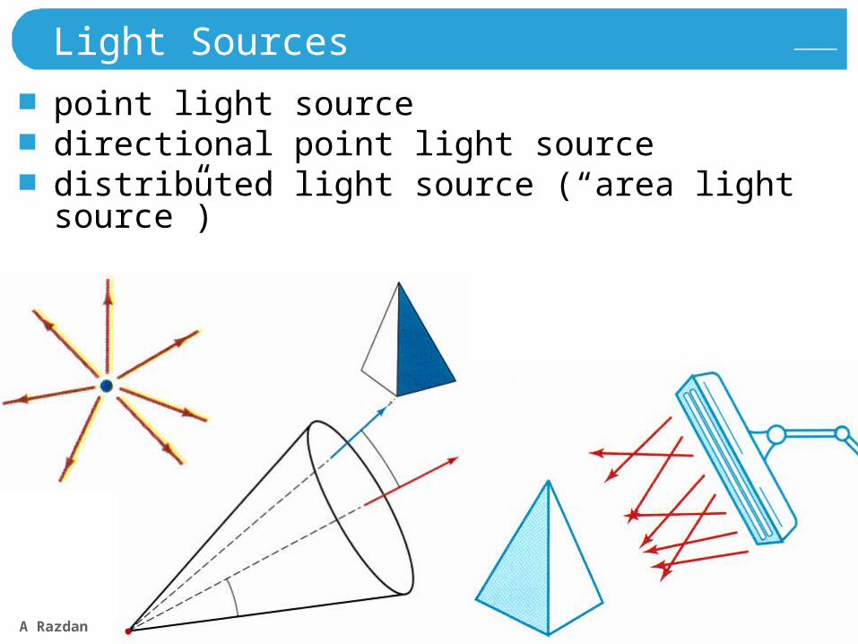
Light Sources
point light sourcedirectional point light sourcedistributed light source (“area light source”)
A Razdan 7
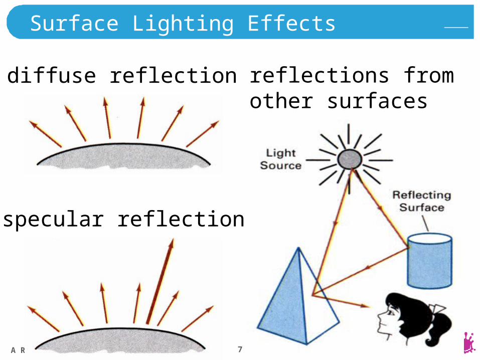
Surface Lighting Effects
diffuse reflection
specular reflection
reflections fromother surfaces
A Razdan 8
Basic Illumination Models
empirical modelslighting calculations
surface properties (glossy, matte, opaque,…)
background lighting conditionslight-source specificationreflection, absorption
ambient light (background light) Iaapproximation of global diffuse lighting effects
A Razdan 9
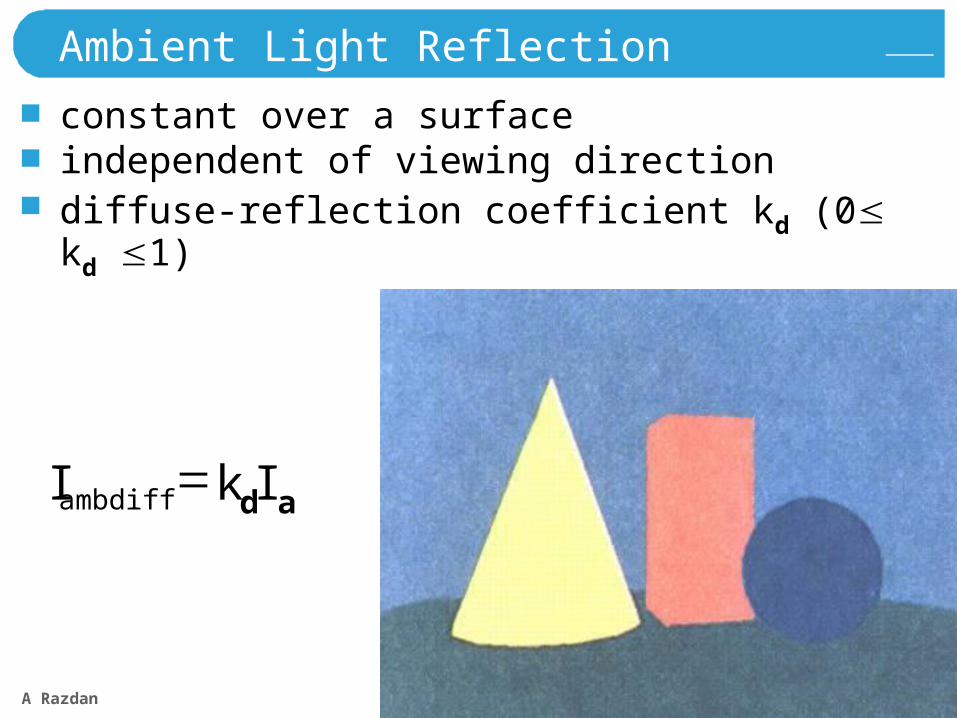
Ambient Light Reflection
constant over a surfaceindependent of viewing directiondiffuse-reflection coefficient kd (0 kd 1)
adambdiff IkI
A Razdan 10
Illumination and Shading
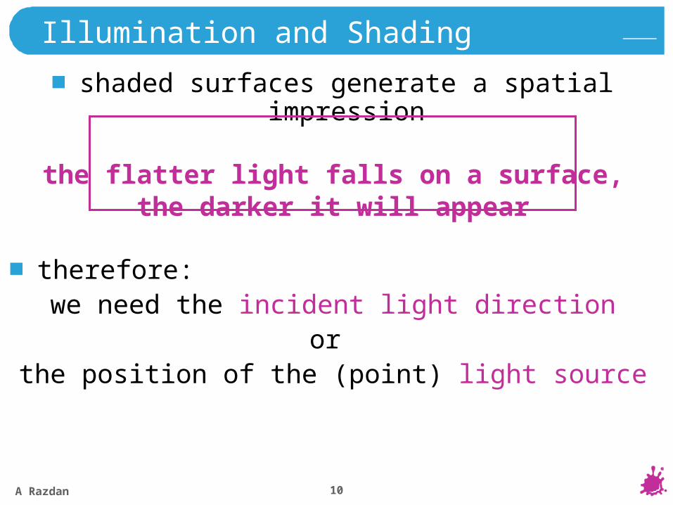
shaded surfaces generate a spatial impression
the flatter light falls on a surface,the darker it will appear
therefore:we need the incident light direction
or the position of the (point) light source
A Razdan 11
..
L
L
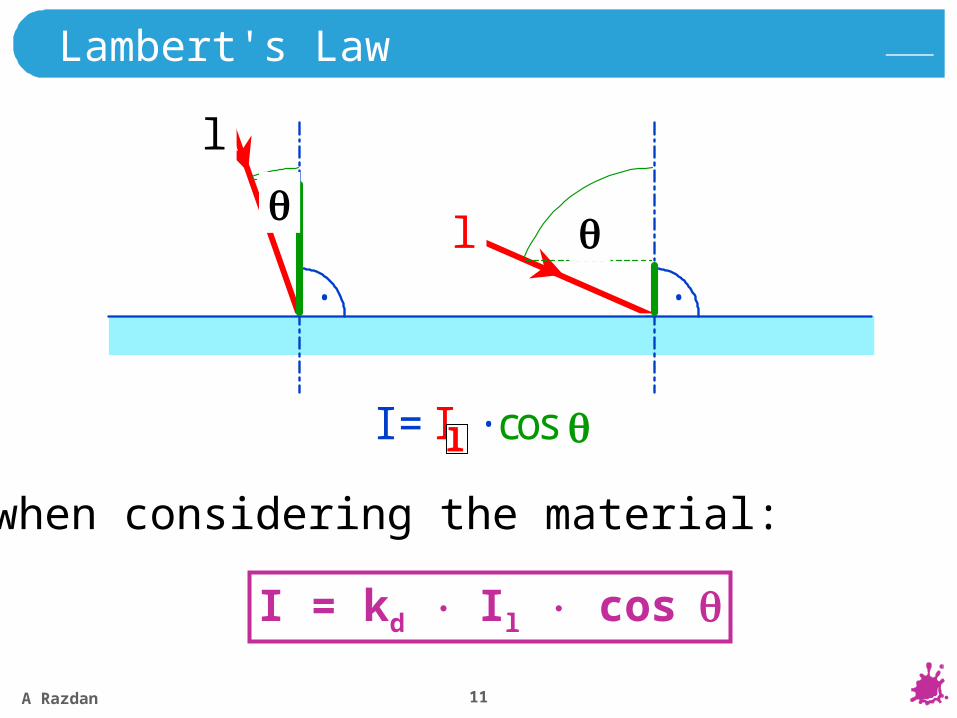
I = IL · cos
Lambert's Law
when considering the material:
I = kd Il cos
l
l
l
A Razdan 12
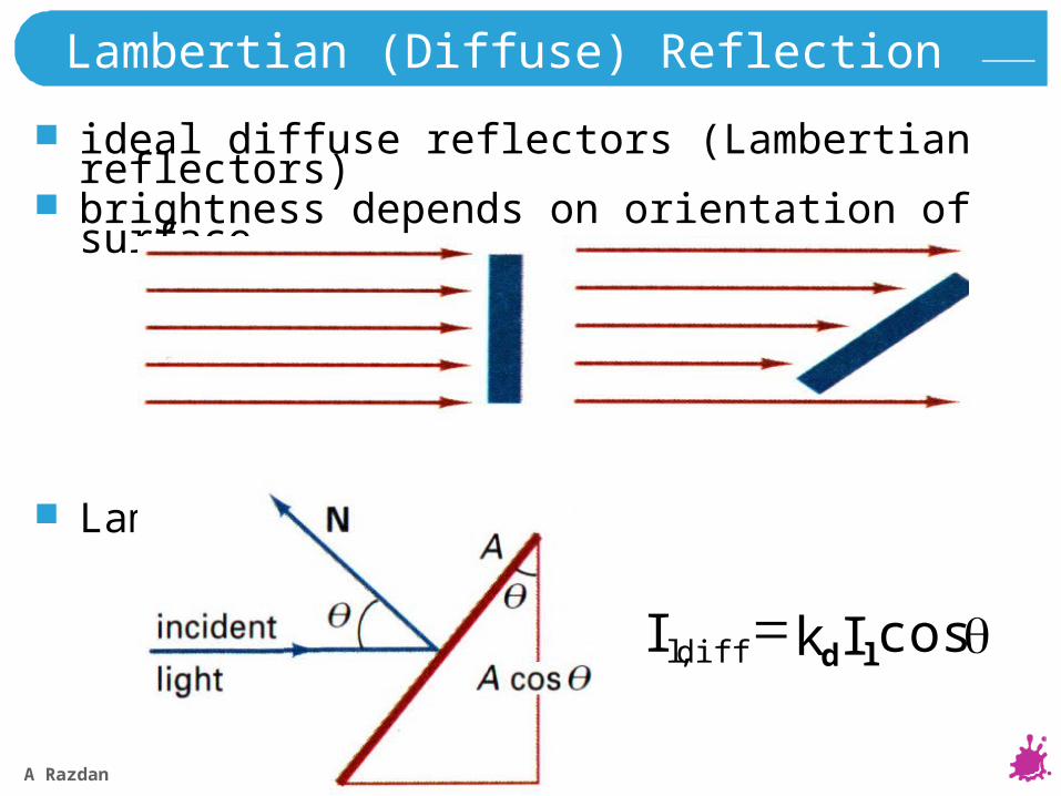
Lambertian (Diffuse) Reflection
ideal diffuse reflectors (Lambertian reflectors)brightness depends on orientation of surface
Lambert’s cosine law
cos, lddiffl IkI
A Razdan 13
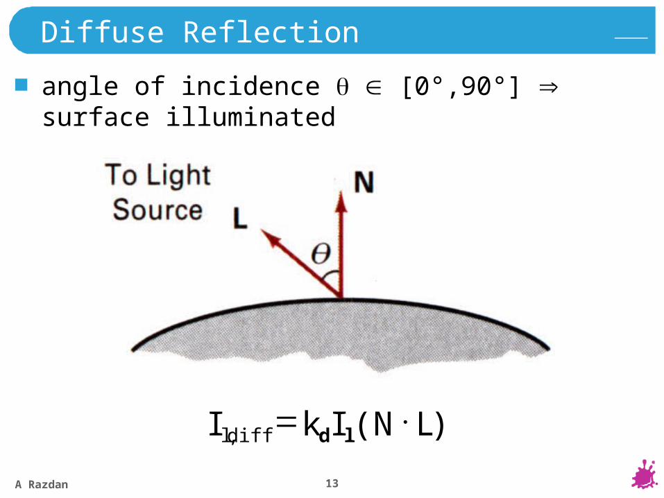
Diffuse Reflection
angle of incidence [0°,90°] surface illuminated
)(, LNIkI lddiffl
A Razdan 14
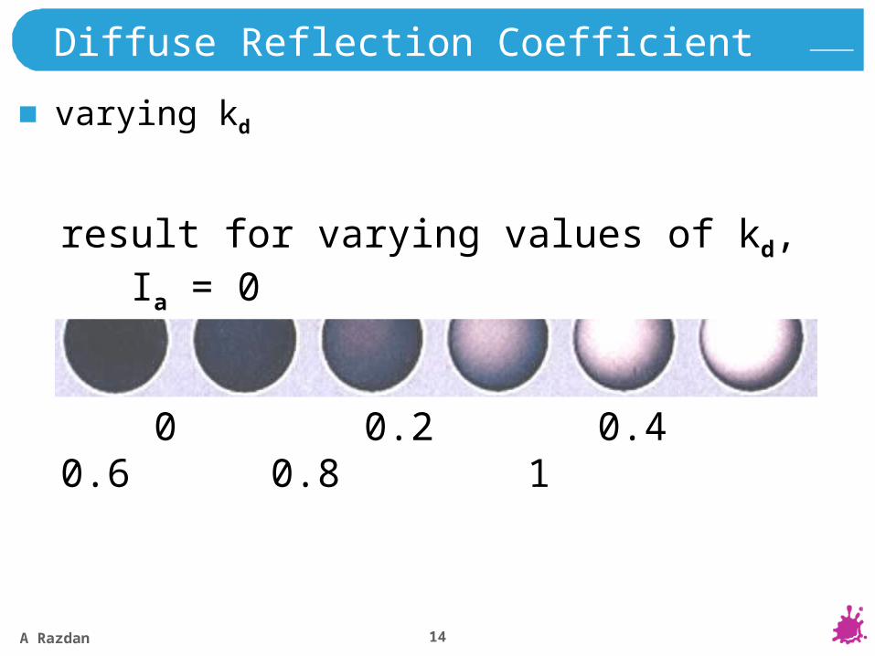
Diffuse Reflection Coefficient
varying kd
result for varying values of kd, Ia = 0
0 0.2 0.4 0.6 0.8 1
A Razdan 15
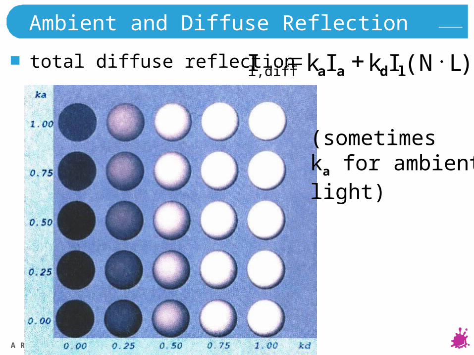
Ambient and Diffuse Reflection
total diffuse reflection )( LNIkIkI ldaal,diff
(sometimeska for ambientlight)
A Razdan 16
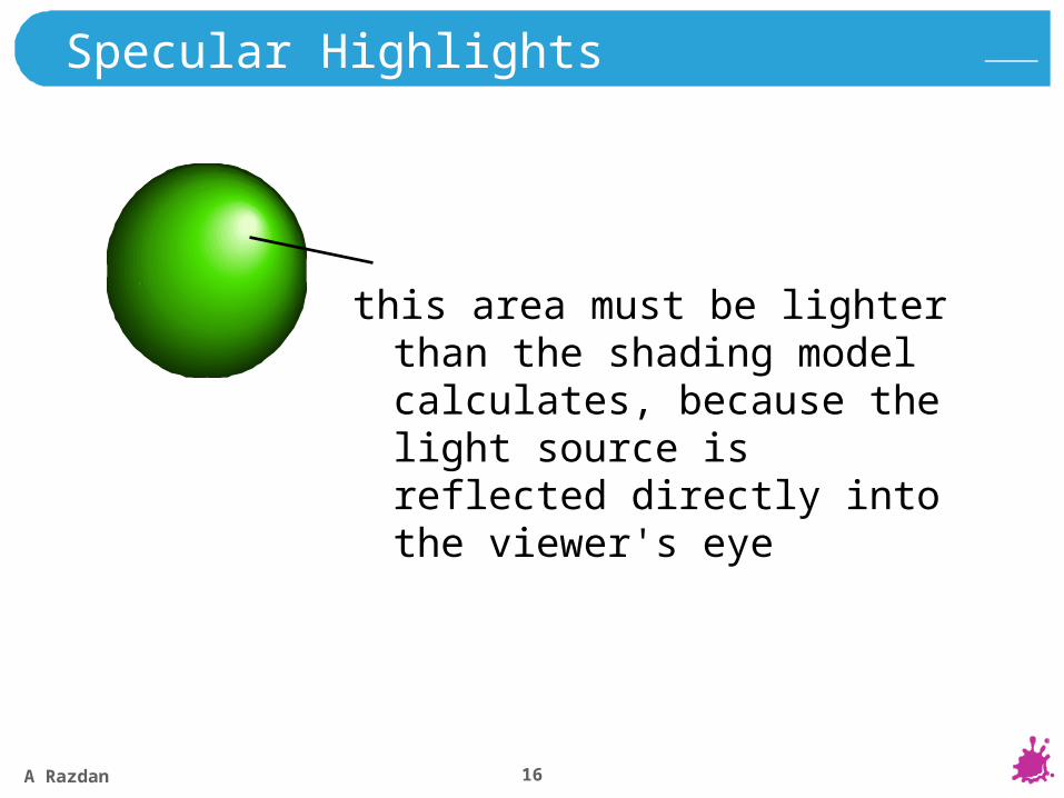
Specular Highlights
this area must be lighter than the shading model calculates, because the light source is reflected directly into the viewer's eye
A Razdan 17
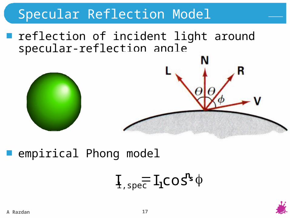
Specular Reflection Model
reflection of incident light around specular-reflection angle
empirical Phong model
snll,spec II cos
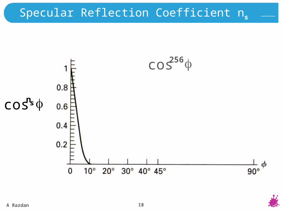
A Razdan 18
cos 8cos 64cos 128cos 256cos
Specular Reflection Coefficient ns
sncos
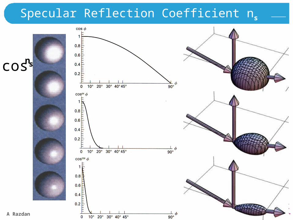
A Razdan 19
cos
64cos
256cos
Specular Reflection Coefficient ns
sncos
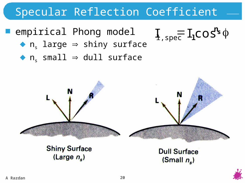
A Razdan 20
Specular Reflection Coefficient
empirical Phong modelns large shiny surface
ns small dull surface
snll,spec II cos
A Razdan 21
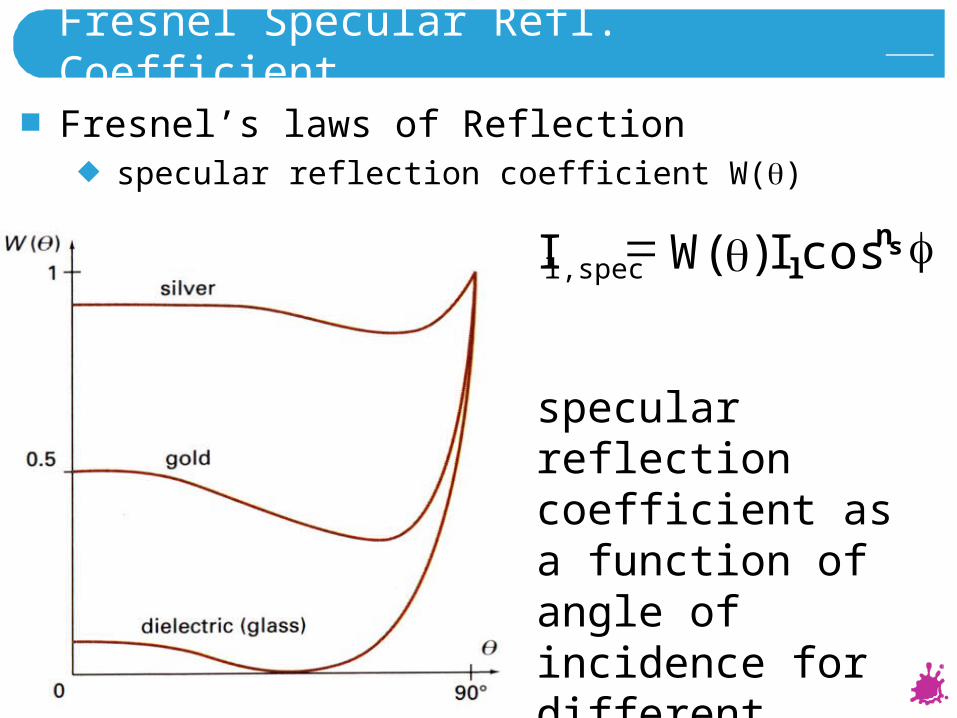
Fresnel Specular Refl. Coefficient
Fresnel’s laws of Reflectionspecular reflection coefficient W()
snll,spec IWI cos)(
specular reflection coefficient as a function of angle of incidence for different materials
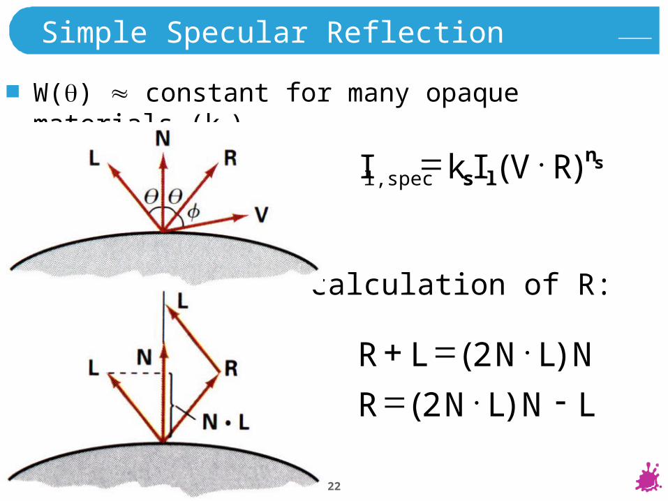
A Razdan 22
NLNLR )2(
calculation of R:
Simple Specular Reflection
W() constant for many opaque materials (ks)
snlsl,spec RVIkI )(
LNLNR )2(
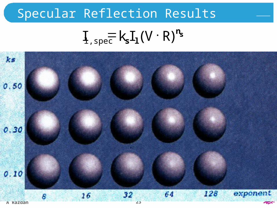
A Razdan 23
Specular Reflection Results
snlsl,spec RVIkI )(
A Razdan 24
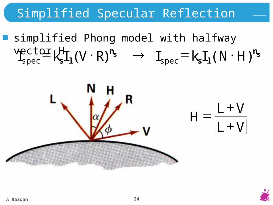
Simplified Specular Reflection
simplified Phong model with halfway vector H
snlsspec RVIkI )( sn
lsspec HNIkI )(
VLVL
H
A Razdan 25
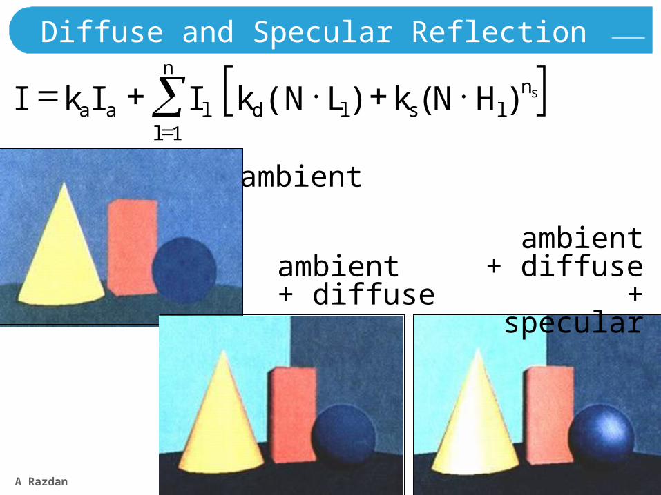
Diffuse and Specular Reflection
n
l
nlsldlaa
sHNkLNkIIkI1
)()(
ambient
ambient+ diffuse
ambient+ diffuse
+ specular
A Razdan 26
Other Aspects
intensity attenuation with distance
anisotropic light sources (Warn model)
transparency (Snell’s law)
atmospheric effects
shadows
…
A Razdan 27
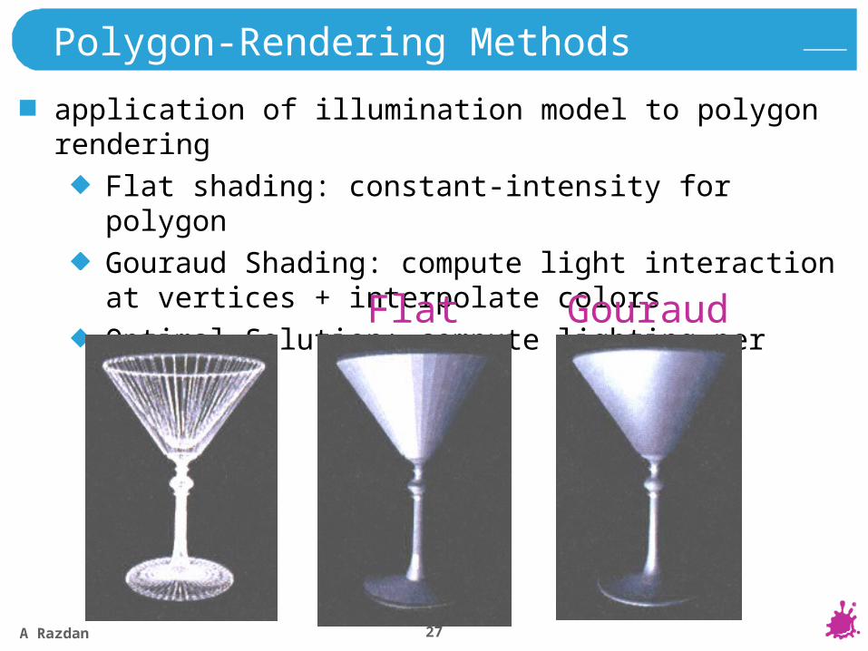
Polygon-Rendering Methods
application of illumination model to polygon rendering
Flat shading: constant-intensity for polygon
Gouraud Shading: compute light interaction at vertices + interpolate colors
Optimal Solution: compute lighting per pixel
Flat Gouraud
A Razdan 28
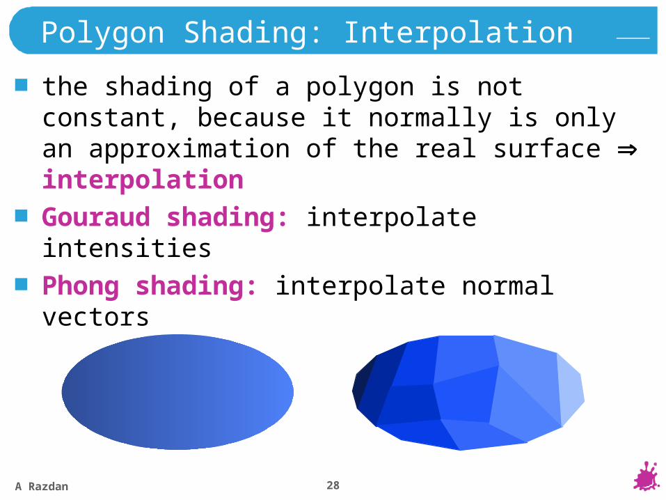
Polygon Shading: Interpolation
the shading of a polygon is not constant, because it normally is only an approximation of the real surface interpolation
Gouraud shading: interpolate intensities
Phong shading: interpolate normal vectors
A Razdan 29
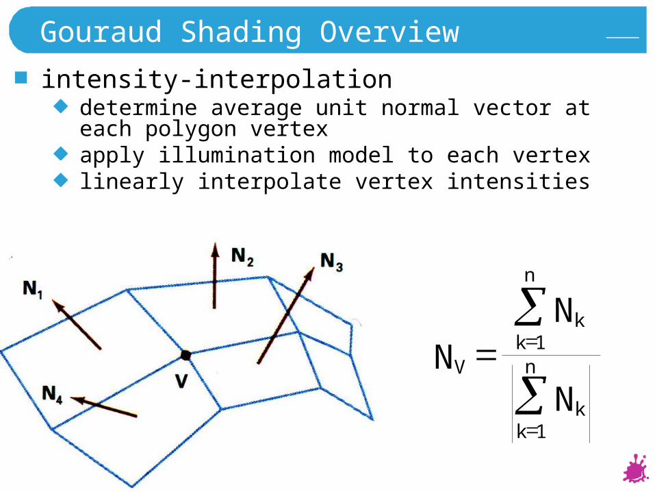
Gouraud Shading Overview
intensity-interpolationdetermine average unit normal vector at each polygon vertexapply illumination model to each vertexlinearly interpolate vertex intensities
n
kk
n
kk
V
N
N
N
1
1
A Razdan 30
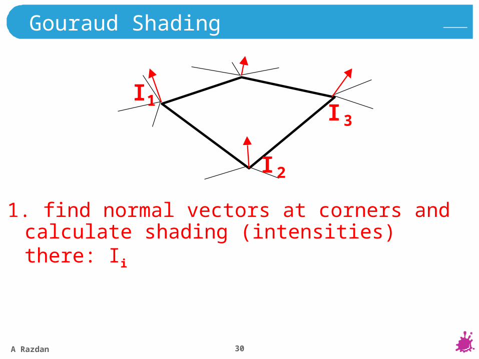
1. find normal vectors at corners and calculate shading (intensities) there: Ii
Gouraud Shading
I 1
I 2
I 3
A Razdan 31
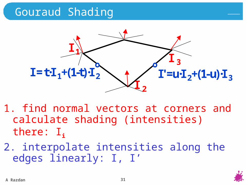
1. find normal vectors at corners and calculate shading (intensities) there: Ii
2. interpolate intensities along the edges linearly: I, I’
Gouraud Shading
I 1
I 2
I 3
I= t·I 1+(1-t)·I 2 I'=u·I 2+(1-u)·I 3
A Razdan 32
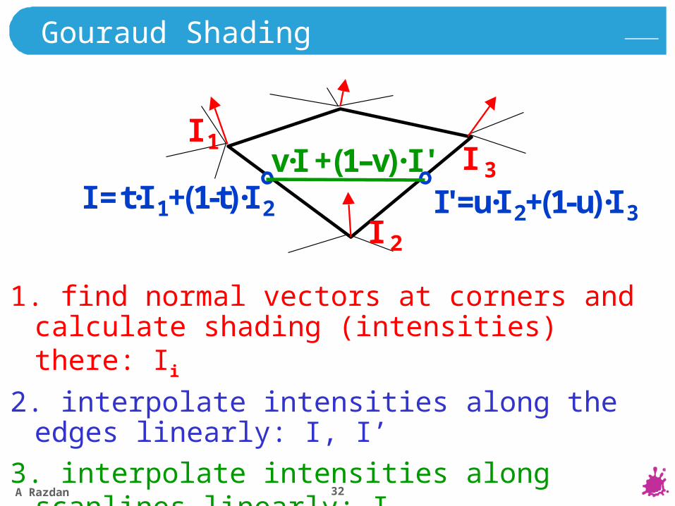
1. find normal vectors at corners and calculate shading (intensities) there: Ii
2. interpolate intensities along the edges linearly: I, I’
3. interpolate intensities along scanlines linearly: Ip
Gouraud Shading
I 1
I 2
I 3
I= t·I 1+(1-t)·I 2 I'=u·I 2+(1-u)·I 3
v·I +(1–v)·I '

A Razdan 33
Gouraud Shading
interpolating intensities
221
411
21
244 I
yyyy
Iyyyy
I
545
44
45
5I
xx
xxI
xx
xxI
ppp

A Razdan 34
Gouraud Shading
incremental update
221
11
21
2I
yyyy
Iyyyy
I
21
12
yyII
II
A Razdan 35
Problems of Gouraud Shading
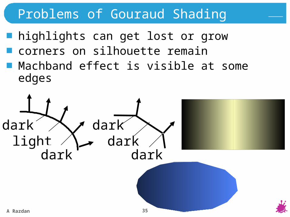
darklight
dark
darkdark
dark
highlights can get lost or growcorners on silhouette remainMachband effect is visible at some edges
A Razdan 36
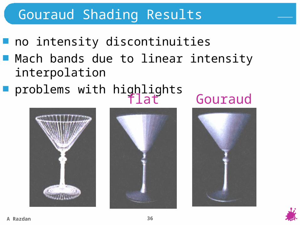
Gouraud Shading Results
no intensity discontinuities
Mach bands due to linear intensity interpolation
problems with highlights
flat Gouraud
A Razdan 37
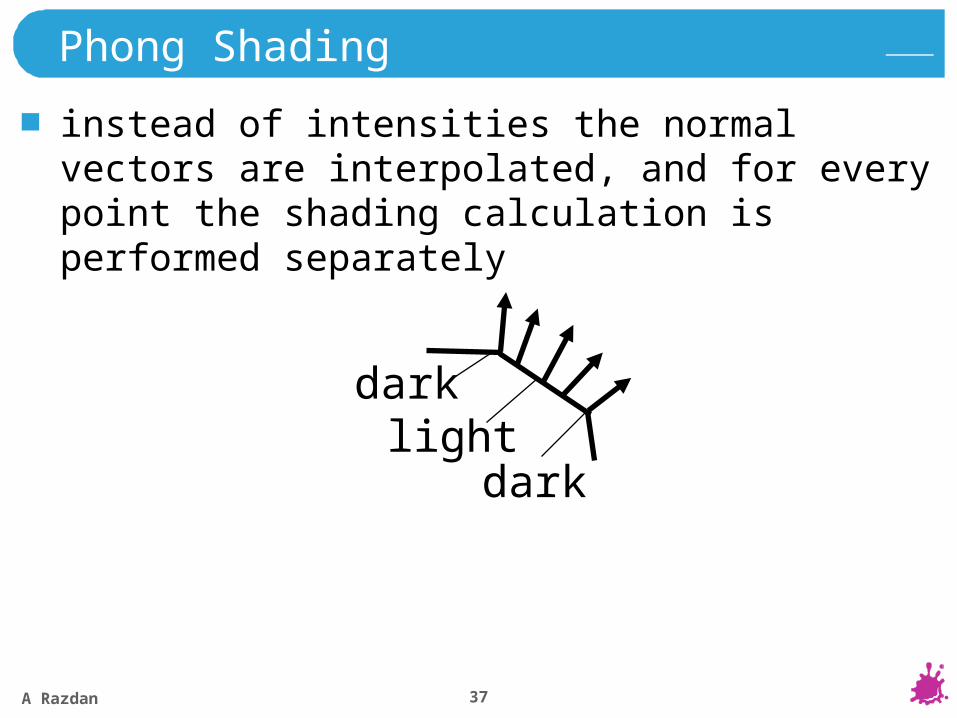
Phong Shading
instead of intensities the normal vectors are interpolated, and for every point the shading calculation is performed separately
darklight
dark
A Razdan 38
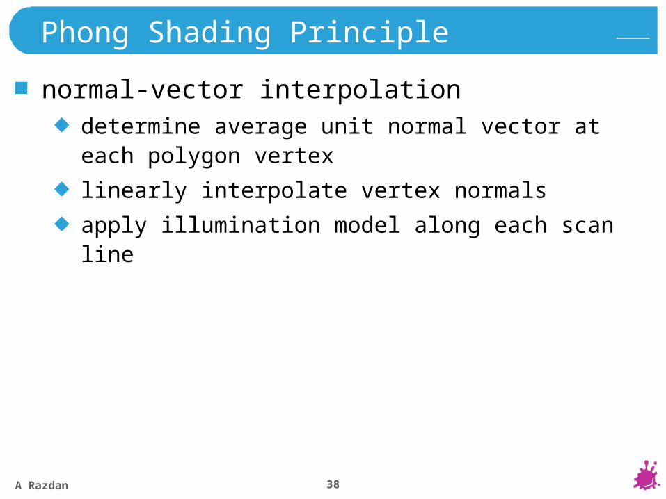
Phong Shading Principle
normal-vector interpolationdetermine average unit normal vector at each polygon vertex
linearly interpolate vertex normals
apply illumination model along each scan line
A Razdan 39
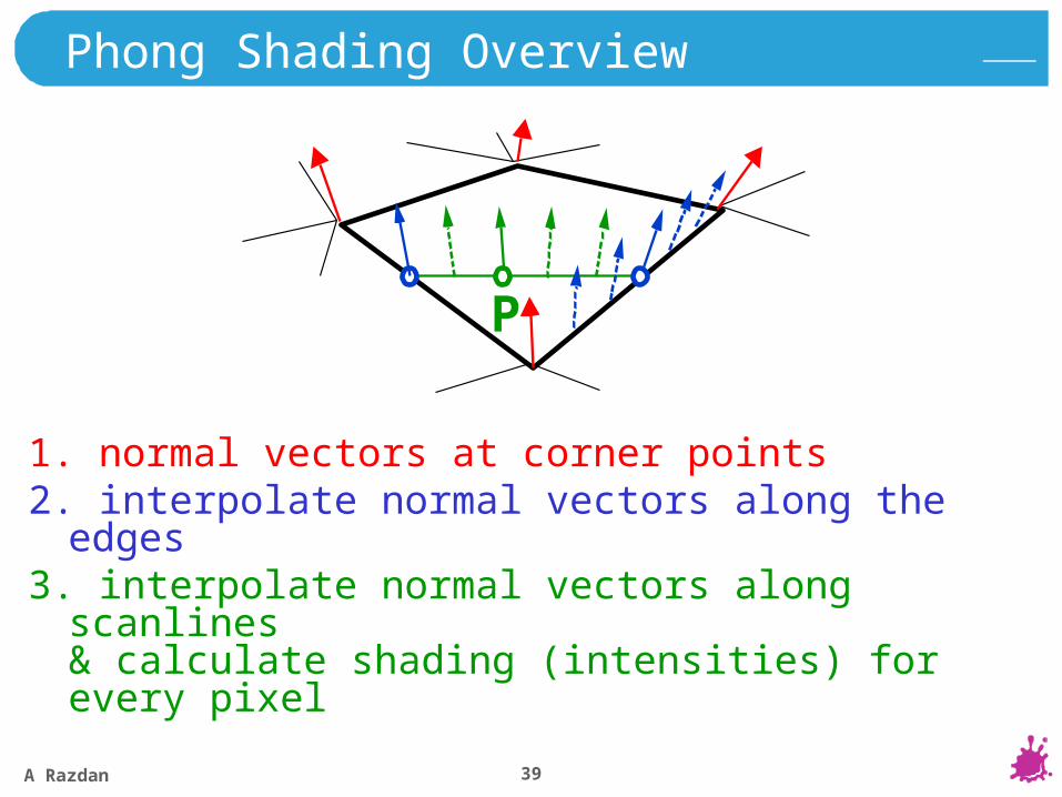
Phong Shading Overview
1. normal vectors at corner points2. interpolate normal vectors along the edges3. interpolate normal vectors along scanlines
& calculate shading (intensities) for every pixel
P
A Razdan 40
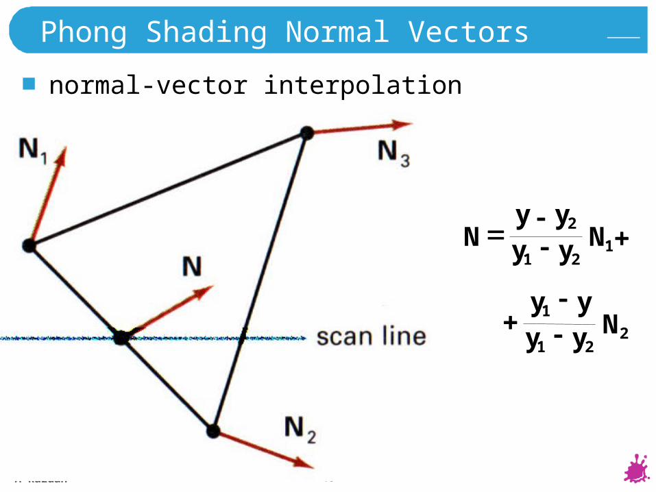
Phong Shading Normal Vectors
normal-vector interpolation
221
1Nyy
yy
121
2Nyy
yyN
A Razdan 41
Phong Shading
incremental normal vector update along and between scan lines
comparison to Gouraud shadingbetter highlights
less Mach banding
more costly
A Razdan 42
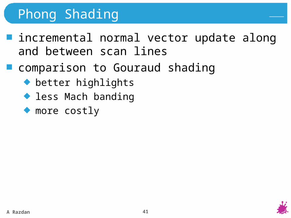
Ray Tracing Concepts
visibility calculation
L1
1
shading
L2 2nd light source
2
light source
A Razdan 43
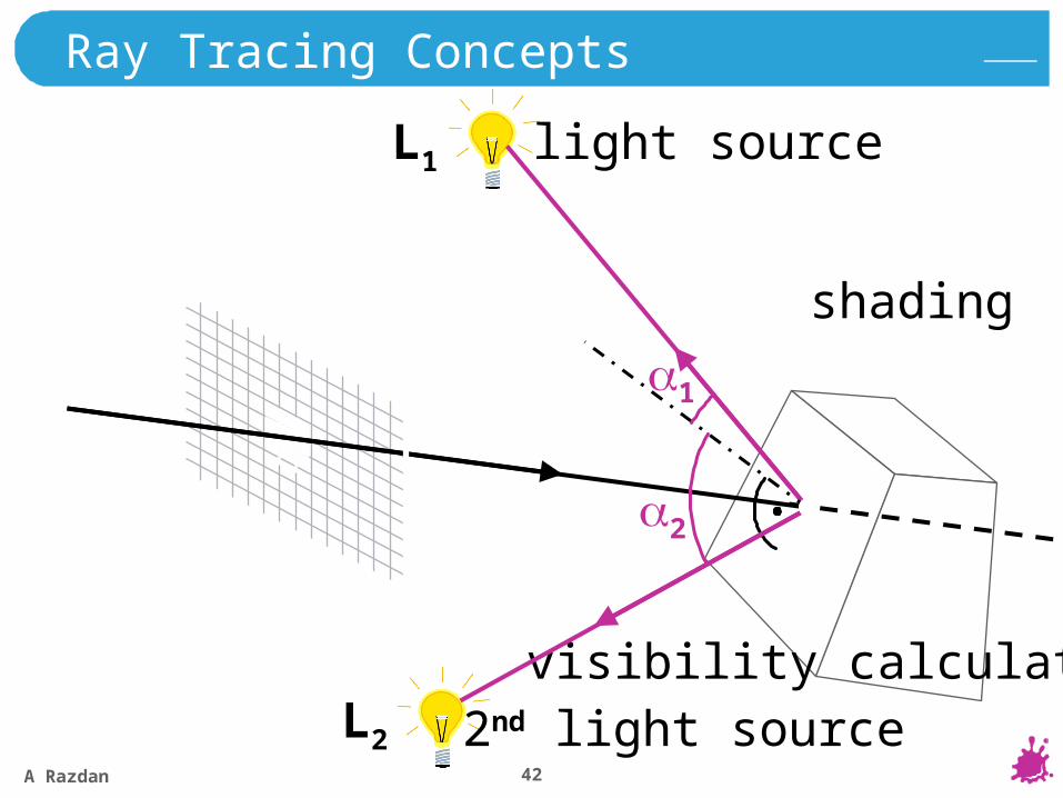
Ray Tracing Concepts
L1
L2
shadows
reflection
shading of the reflected object
A Razdan 44
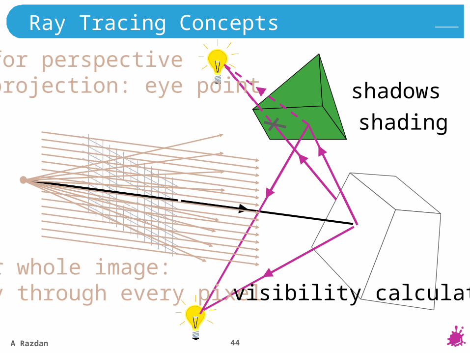
Ray Tracing Concepts
for whole image:ray through every pixel
shadows
reflection
visibility calculation
shading
for perspectiveprojection: eye point
A Razdan 45
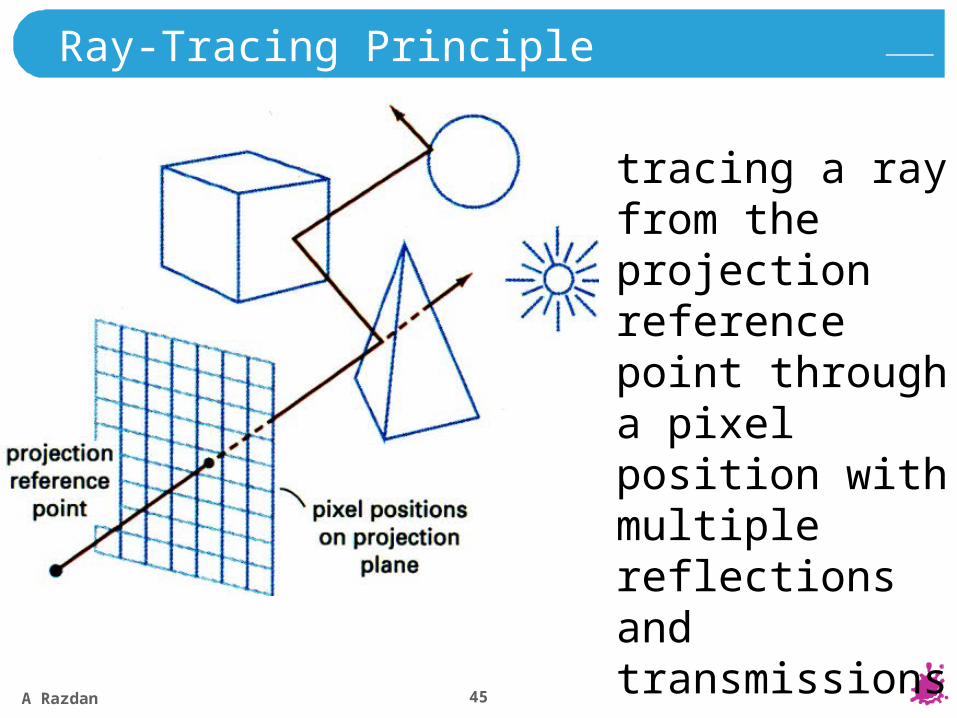
Ray-Tracing Principle
tracing a ray from the projection reference point through a pixel position with multiple reflections and transmissions
A Razdan 46
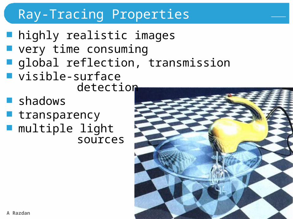
Ray-Tracing Properties
highly realistic imagesvery time consumingglobal reflection, transmissionvisible-surface
detectionshadowstransparencymultiple light
sources
A Razdan 47
Ray-Tracing
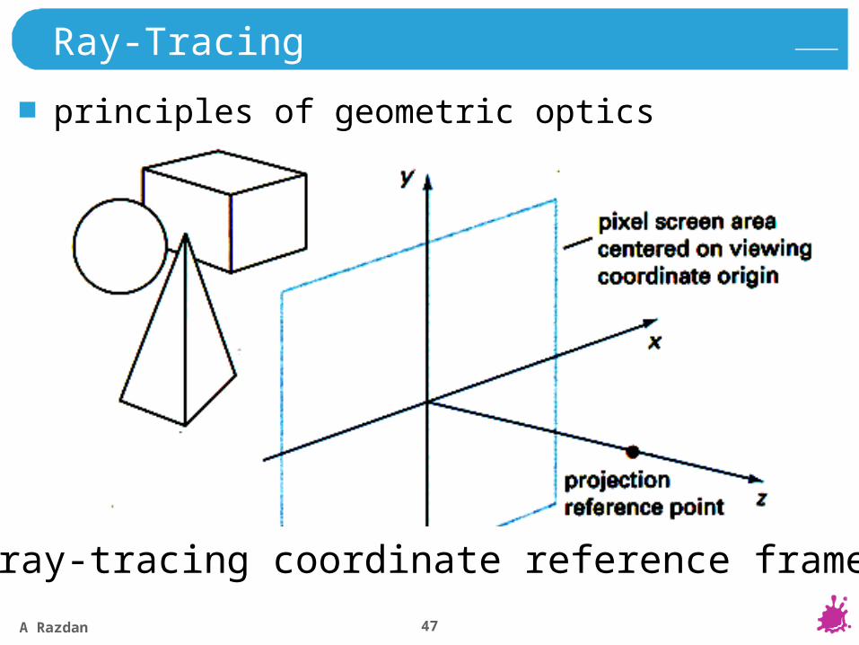
principles of geometric optics
ray-tracing coordinate reference frame

A Razdan 48
Shading: Diffuse Shading
Id … illumination caused by diffuse shadingxxx … any shading model
(Phong, Blinn, Cook/Torrance,…)
Id = xxx
A Razdan 49
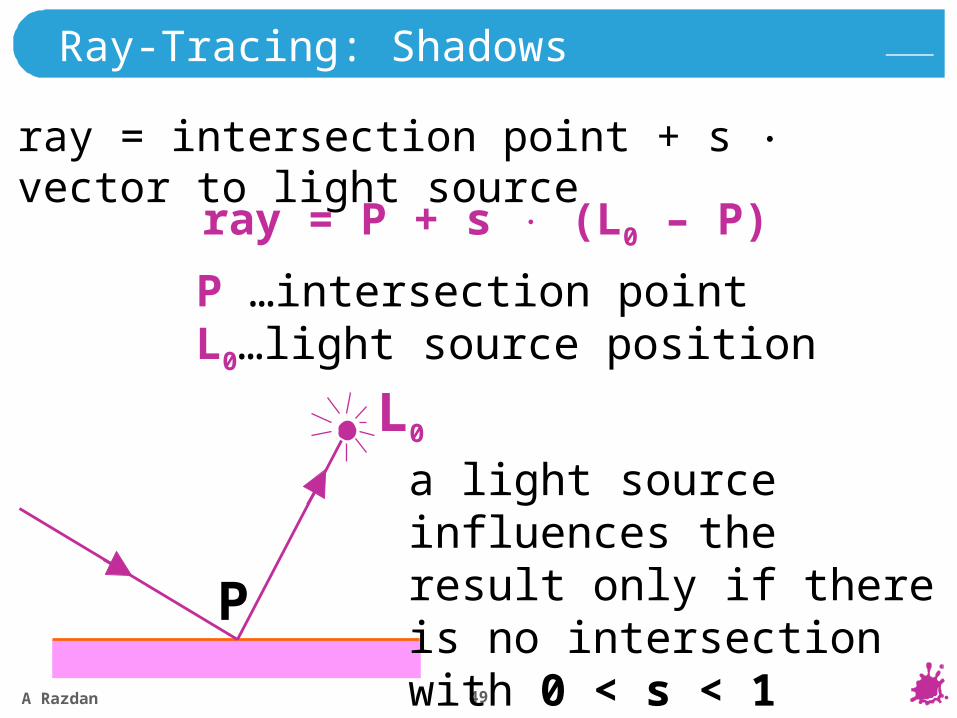
Ray-Tracing: Shadows
P
L0
a light source influences the result only if there is no intersection with 0 < s < 1
ray = intersection point + s vector to light source
ray = P + s (L0 – P)
P …intersection pointL0…light source position
A Razdan 50
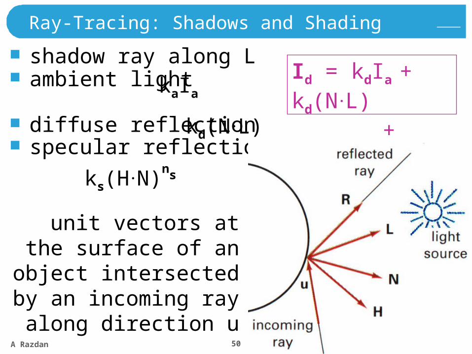
Ray-Tracing: Shadows and Shading
shadow ray along Lambient light
diffuse reflectionspecular reflection
kaIa
kd(N.L)
ks(H.N)ns
unit vectors at the surface of an object
intersected by an incoming ray along
direction u
Id = kdIa + kd(N.L)
+ ks(H.N)ns
A Razdan 51
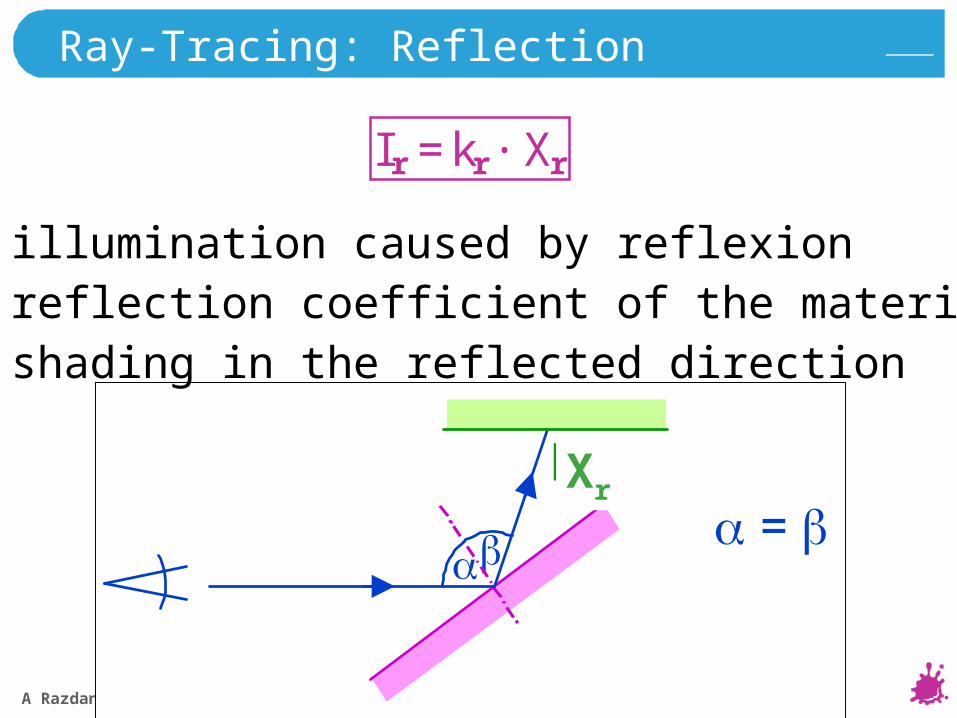
Ray-Tracing: Reflection
Ir = kr · Xr
=
Hr
Ir … illumination caused by reflexionkr … reflection coefficient of the materialXr … shading in the reflected direction
Xr
A Razdan 52
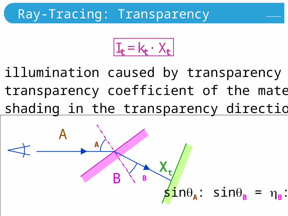
Ray-Tracing: Transparency
A
B
It = kt · Xt
It … illumination caused by transparencykt … transparency coefficient of the materialXt … shading in the transparency direction
Xt
A
B
sinA::sinB = B:A
A Razdan 53
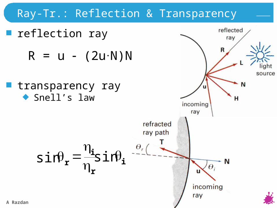
Ray-Tr.: Reflection & Transparency
reflection ray
transparency raySnell’s law
ir
ir
sinsin
R = u (2u.N)N
A Razdan 54
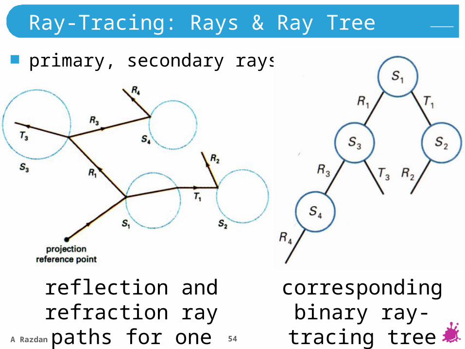
Ray-Tracing: Rays & Ray Tree
primary, secondary rays
corresponding binary ray-tracing tree
reflection and refraction ray paths for one pixel
A Razdan 55
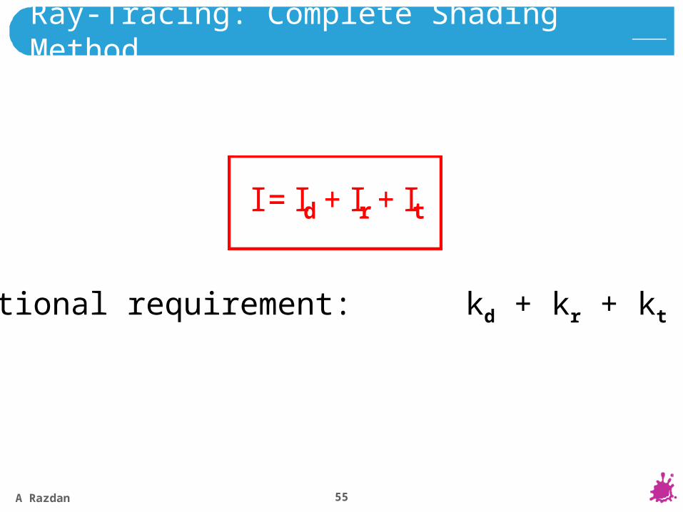
Ray-Tracing: Complete Shading Method
I = Id + Ir + It
additional requirement: kd + kr + kt 1
A Razdan 56
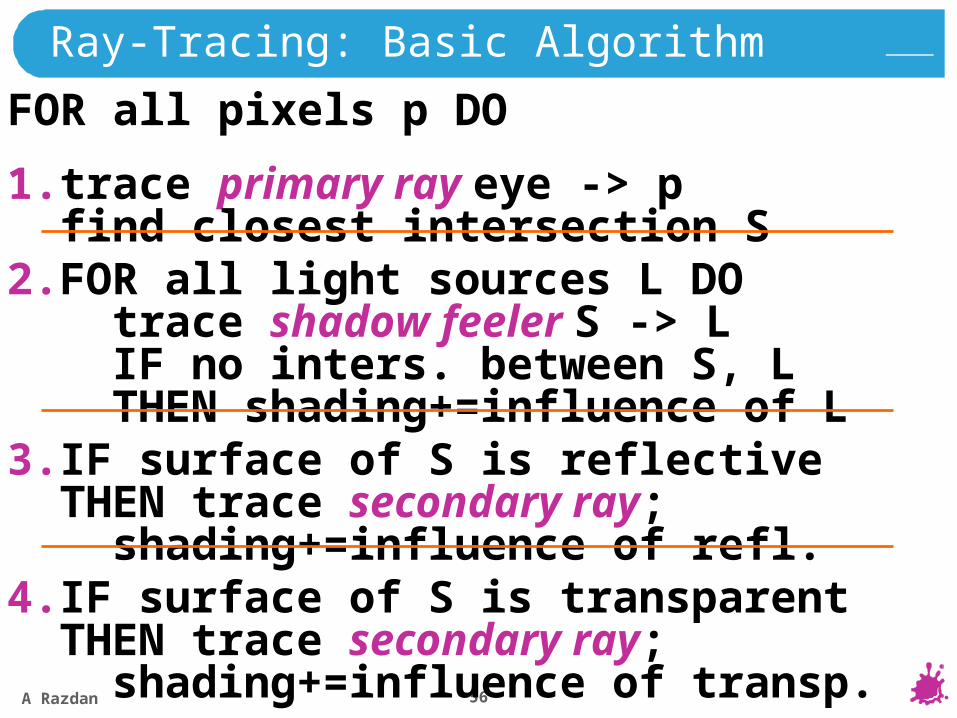
4.IF surface of S is transparent THEN trace secondary ray; shading+=influence of transp.
3.IF surface of S is reflective THEN trace secondary ray; shading+=influence of refl.
2.FOR all light sources L DO trace shadow feeler S -> L IF no inters. between S, L THEN shading+=influence of L
1.trace primary ray eye -> p find closest intersection S
FOR all pixels p DO
Ray-Tracing: Basic Algorithm
A Razdan 57
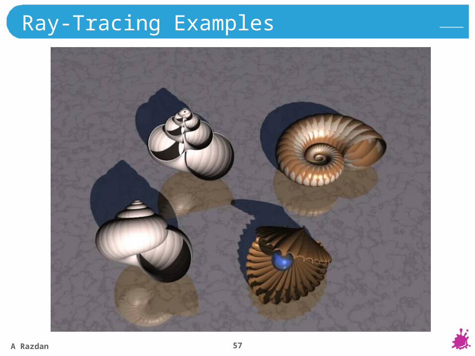
Ray-Tracing Examples
A Razdan 58
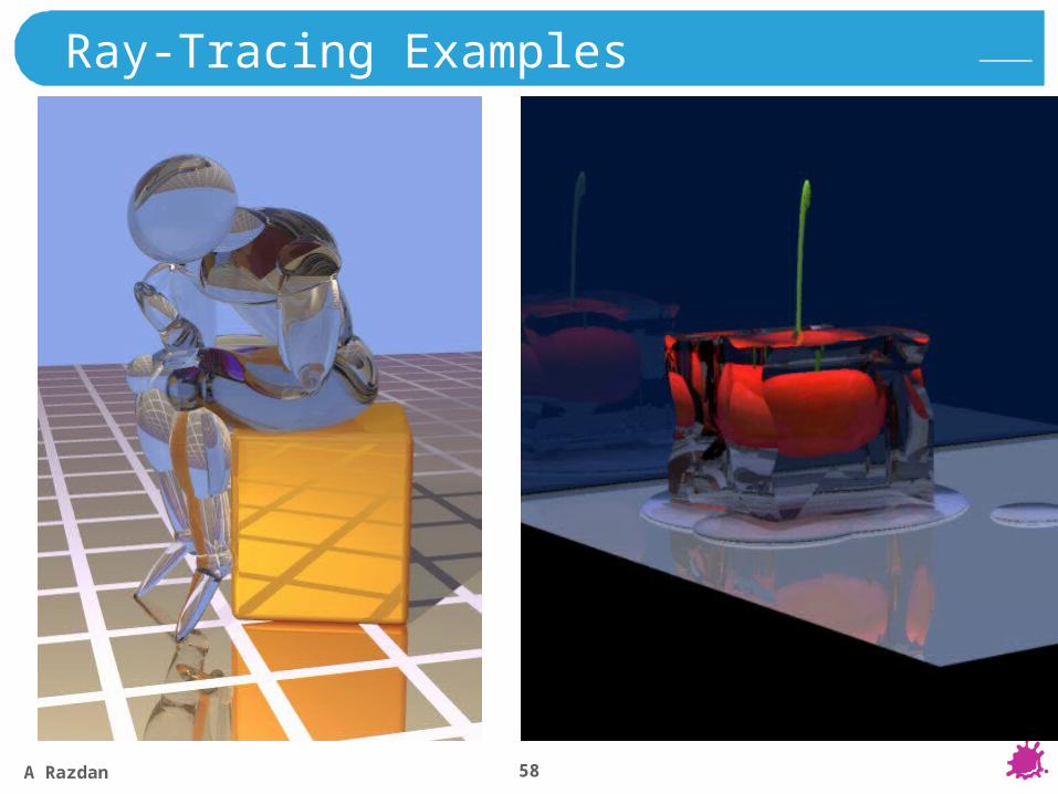
Ray-Tracing Examples
A Razdan 59
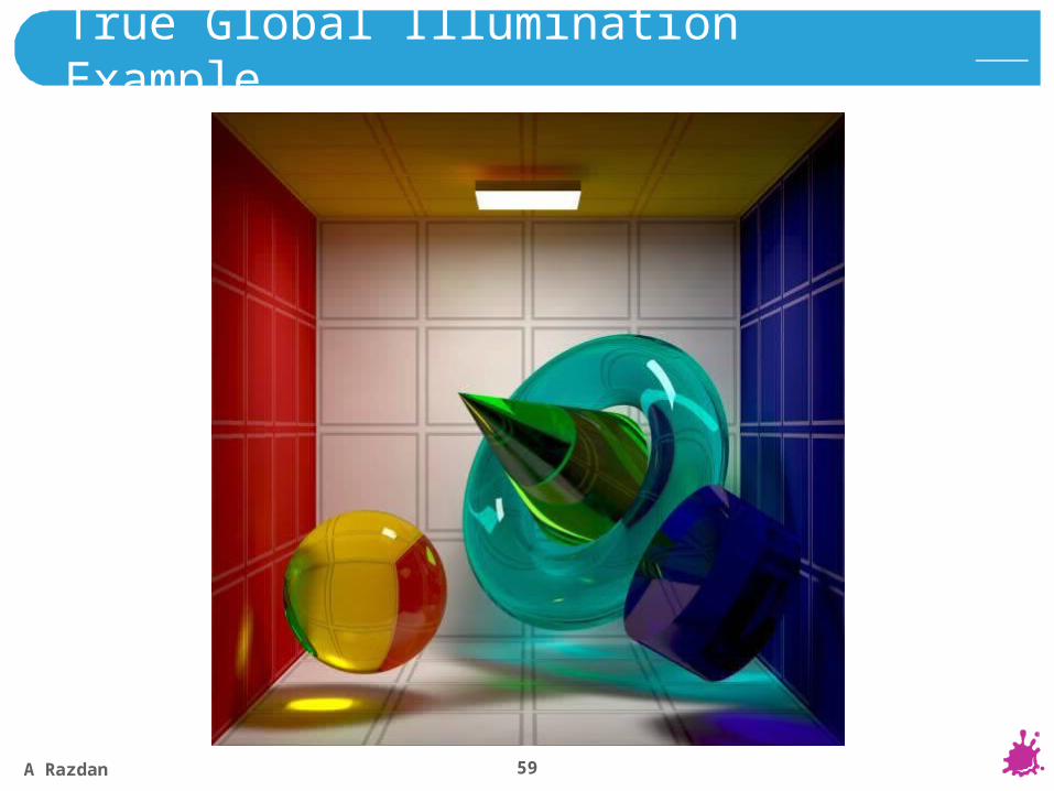
True Global Illumination Example
A Razdan 60
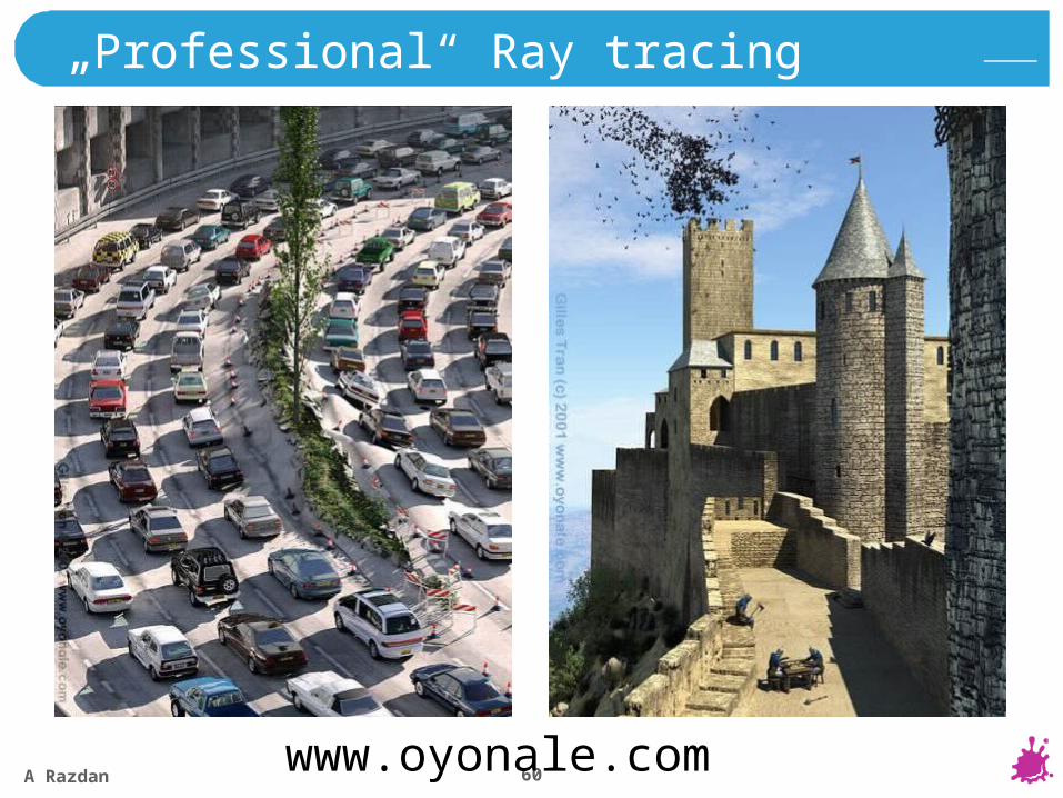
„Professional“ Ray tracing
www.oyonale.com

A Razdan 61
Requirements for Object Data(to use them for ray-tracing)
intersection calculation ray - object possible
surface normal calculation possibleB-Rep: simple
CSG: recursive evaluation
A Razdan 62
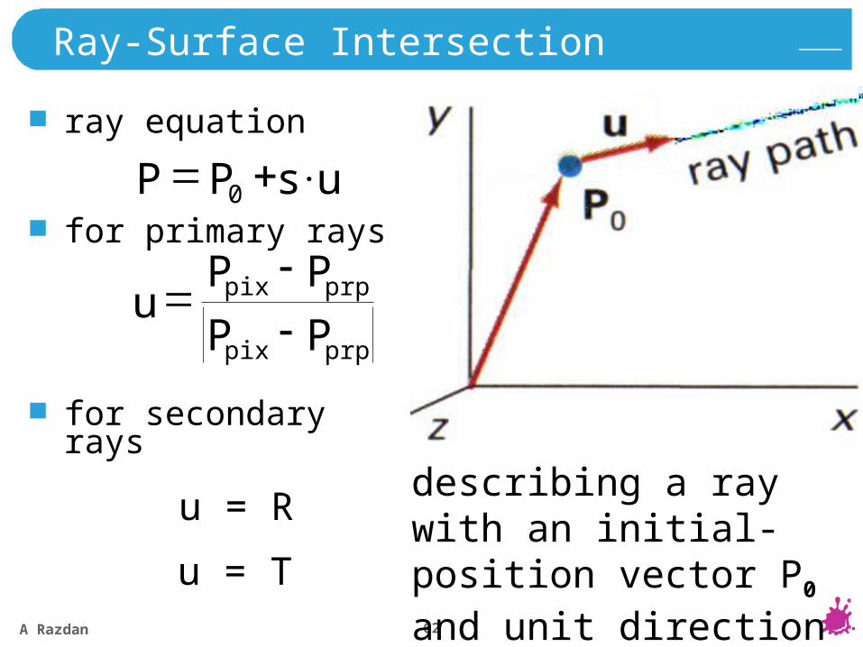
Ray-Surface Intersection
ray equation
for primary rays
for secondaryrays
s.uPP 0
prppix
prppix
PP
PPu
u = R
u = T
describing a ray with an initial-position vector P0 and unit direction vector u
A Razdan 63
r
P0
Pc
Pu
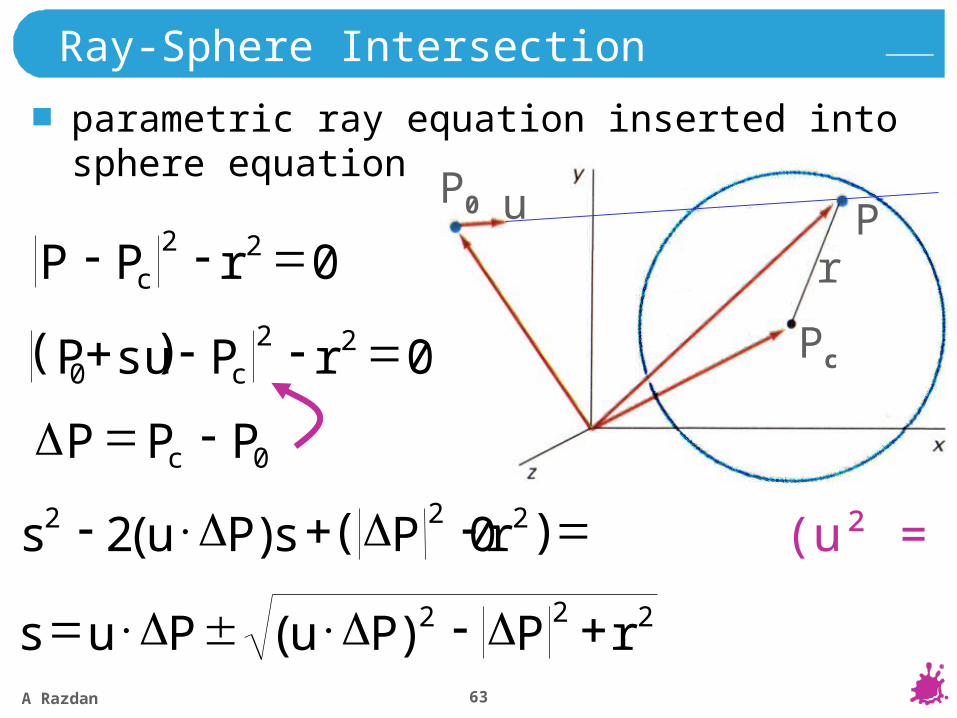
Ray-Sphere Intersection
parametric ray equation inserted into sphere equation
022 rPP c
022 0 rPsu P c
0 (u² = 1))(2 222 rPsPus
222)( rPPuPus
0PPP c
( )
( )
A Razdan 64
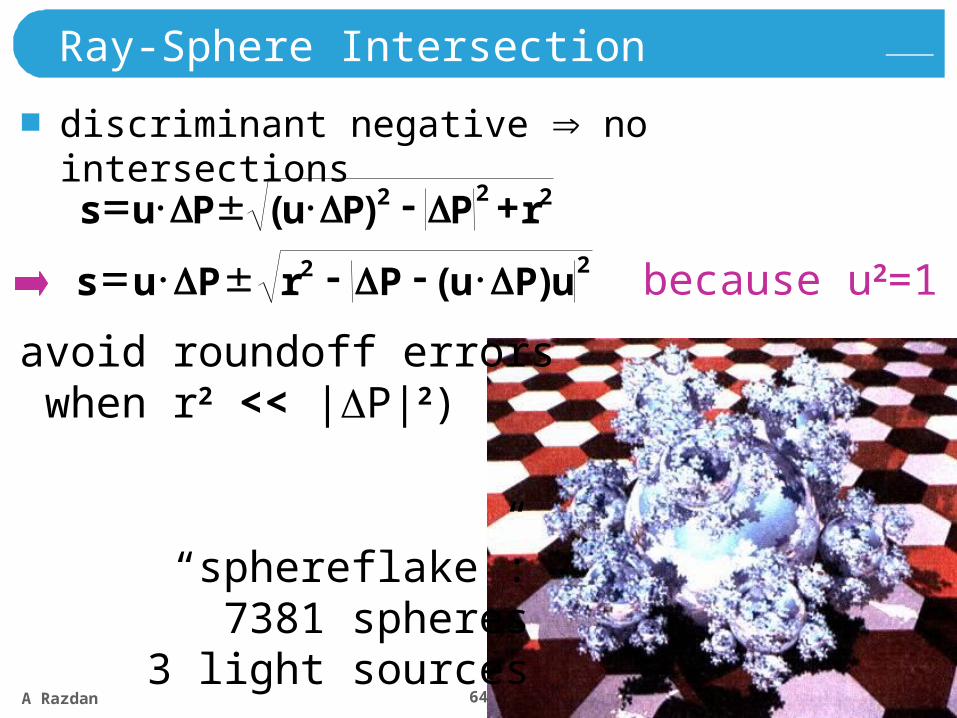
Ray-Sphere Intersection
discriminant negative no intersections
222)( rPPuPus
“sphereflake”:7381 spheres
3 light sources
22 )( uPuPrPus because u2=1
(to avoid roundoff errors when r2 << |P|2)

A Razdan 65
Sphereflake
A Razdan 66
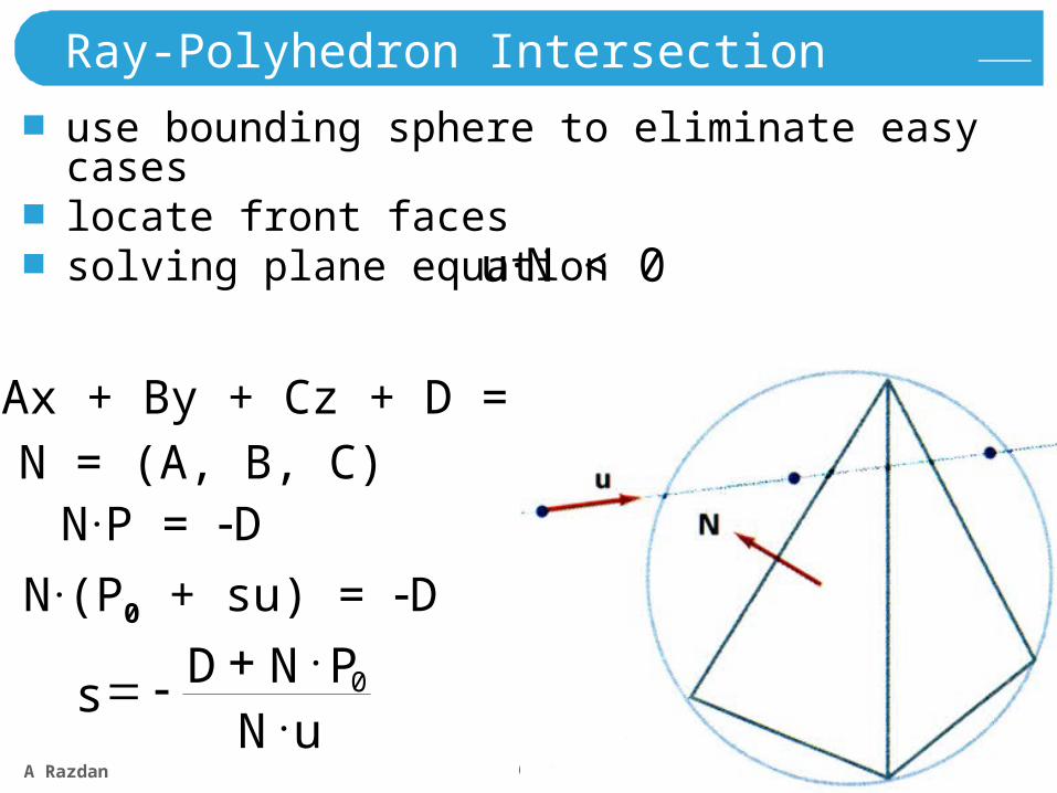
Ray-Polyhedron Intersection
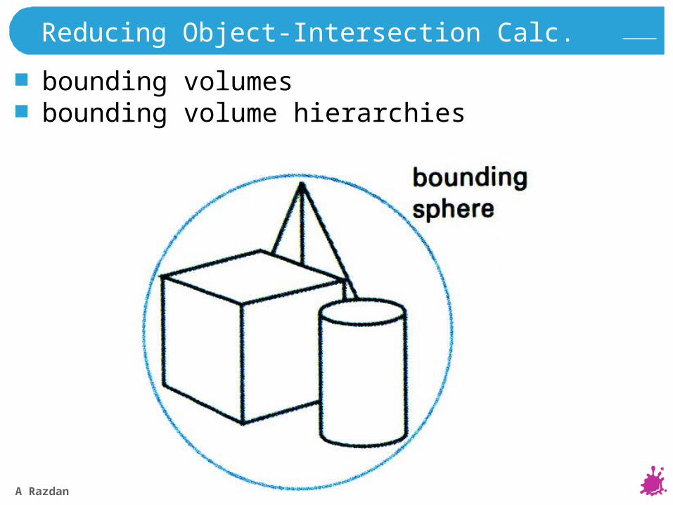
use bounding sphere to eliminate easy caseslocate front facessolving plane equation
uNPND
s 0
u.N < 0
Ax + By + Cz + D = 0
N.(P0 + su) = DP0
N = (A, B, C)N.P = D
P
P
A Razdan 67
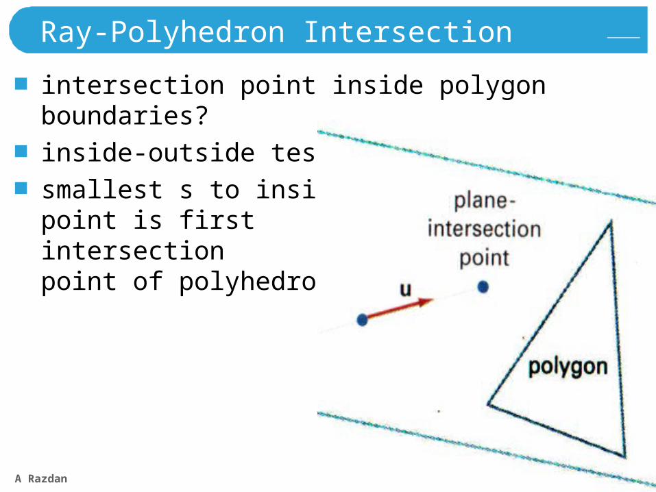
Ray-Polyhedron Intersection
intersection point inside polygon boundaries?
inside-outside test
smallest s to insidepoint is first intersectionpoint of polyhedron
A Razdan 68
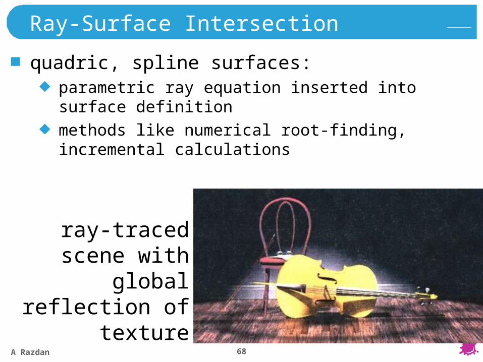
Ray-Surface Intersection
quadric, spline surfaces:parametric ray equation inserted into surface definition
methods like numerical root-finding, incremental calculations
ray-traced scene with global
reflection of texture
A Razdan 69
Reducing Object-Intersection Calc.
bounding volumesbounding volume hierarchies
A Razdan 70
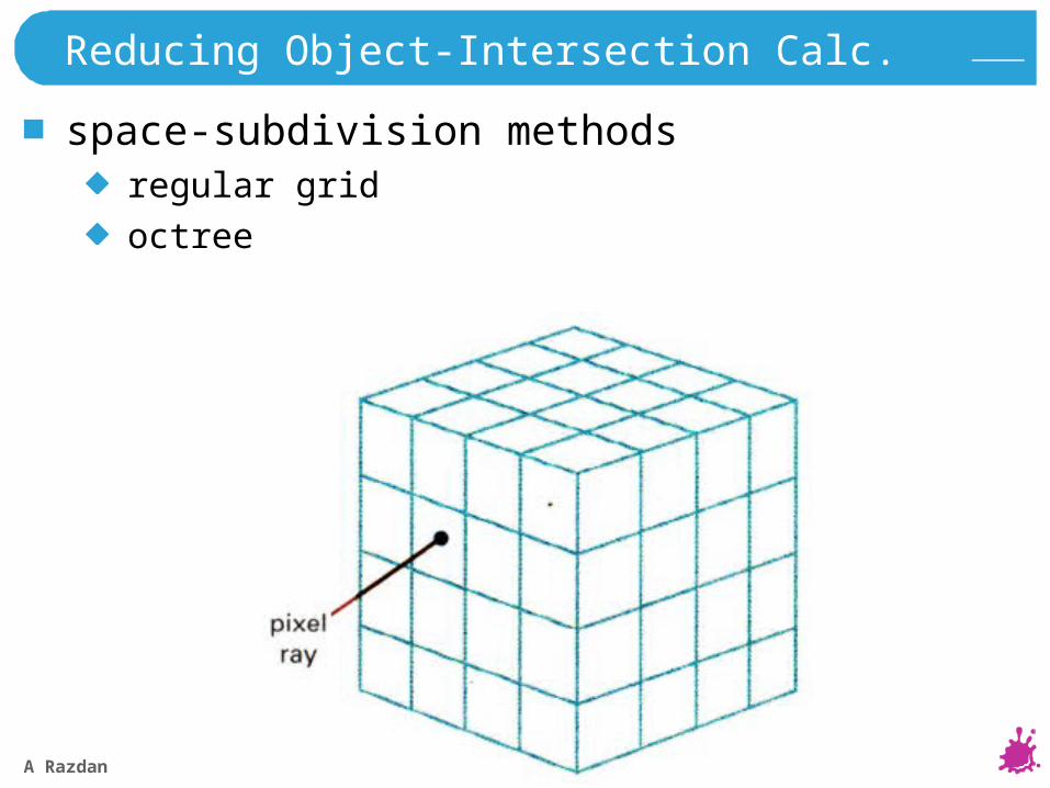
Reducing Object-Intersection Calc.
space-subdivision methodsregular grid
octree
A Razdan 71
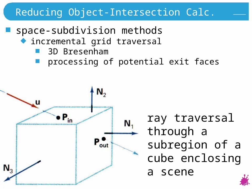
Reducing Object-Intersection Calc.
space-subdivision methodsincremental grid traversal
3D Bresenham processing of potential exit faces
ray traversal through a subregion of a cube enclosing a scene
A Razdan 72
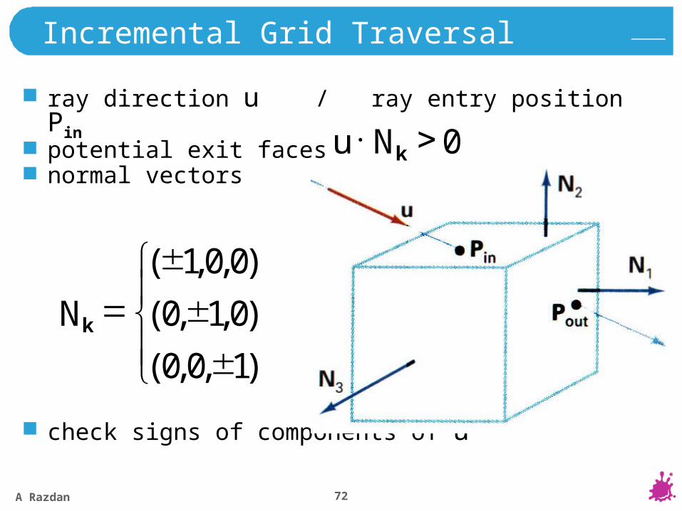
Incremental Grid Traversal
ray direction u / ray entry position Pinpotential exit facesnormal vectors
check signs of components of u
0 kNu
)1,0,0(
)0,1,0(
)0,0,1(
kN
A Razdan 73
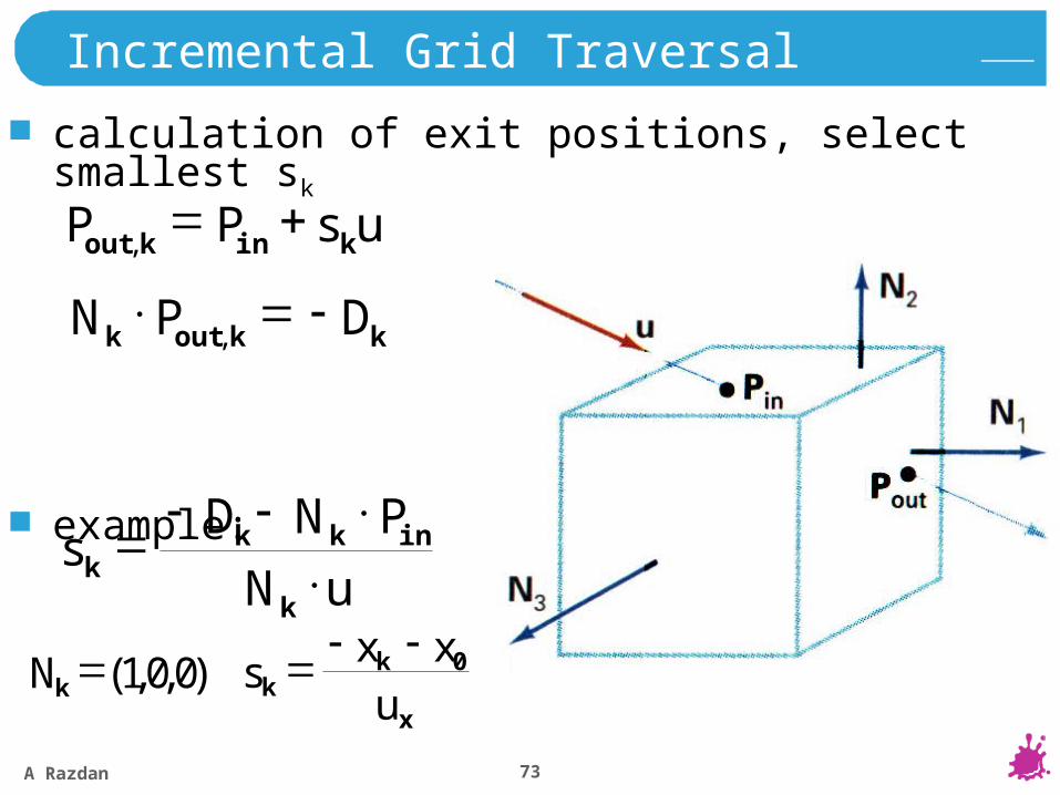
calculation of exit positions, select smallest sk
example:
Incremental Grid Traversal
usPP kinkout
,
DkPN koutk
,
uN
PNDksk
inkk
)0,0,1(kN
x
kk u
xxs 0
A Razdan 74
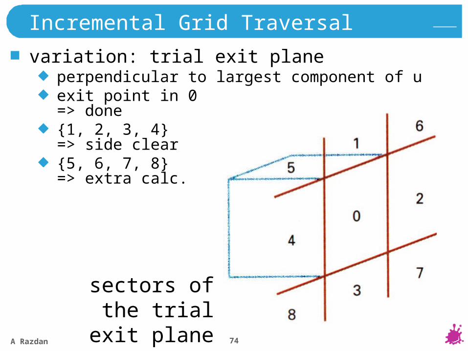
Incremental Grid Traversal
variation: trial exit planeperpendicular to largest component of uexit point in 0=> done{1, 2, 3, 4} => side clear{5, 6, 7, 8}=> extra calc.
sectors of the trial exit plane
A Razdan 75
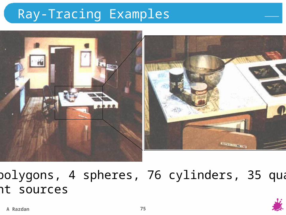
Ray-Tracing Examples
1298 polygons, 4 spheres, 76 cylinders, 35 quadrics5 light sources
A Razdan 76
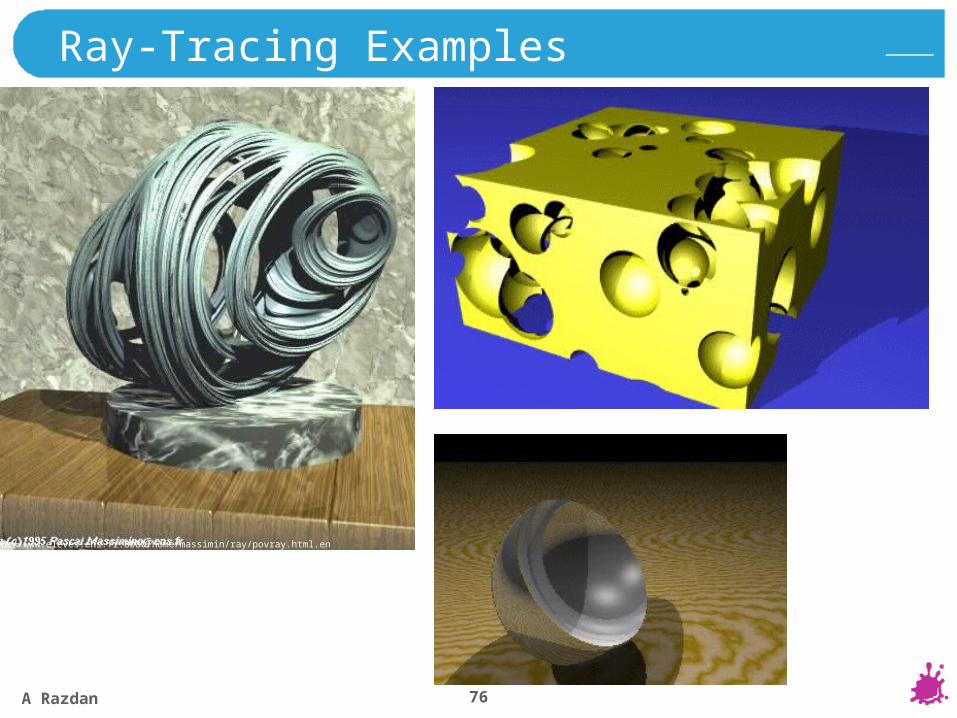
http://www.eleves.ens.fr:8080/home/massimin/ray/povray.html.en
Ray-Tracing Examples
A Razdan 77
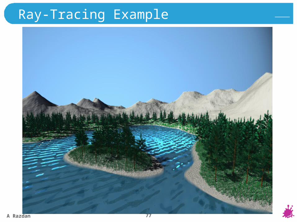
Ray-Tracing Example
A Razdan 78
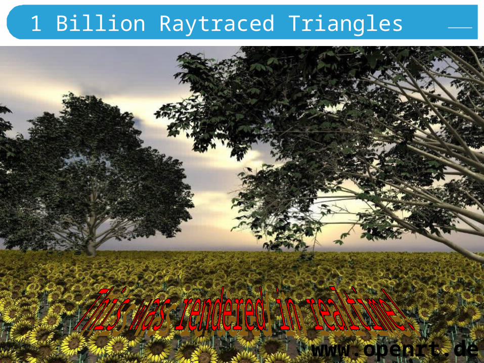
1 Billion Raytraced Triangles
www.openrt.de
A Razdan 79
Radiosity Method
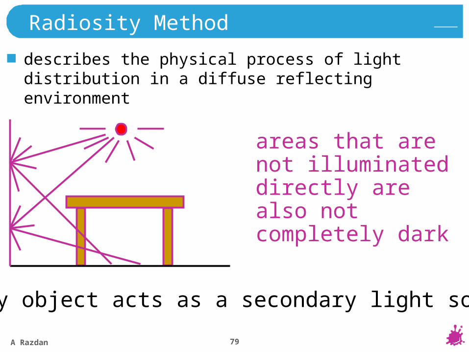
describes the physical process of light distribution in a diffuse reflecting environment
areas that are not illuminated directly are also not completely dark
every object acts as a secondary light source
A Razdan 80
Radiosity
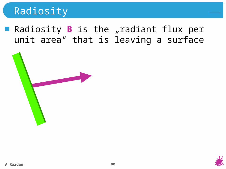
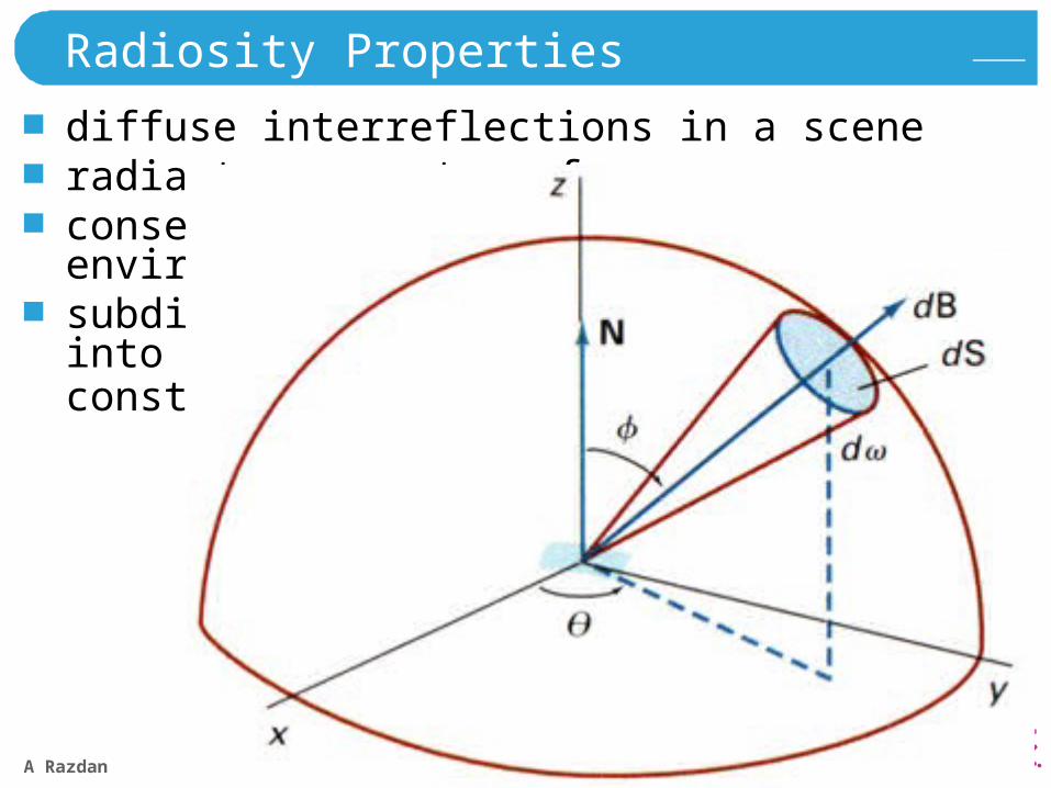
Radiosity B is the „radiant flux per unit area“ that is leaving a surface
A Razdan 81
Radiosity Equation
hemi
k. d B
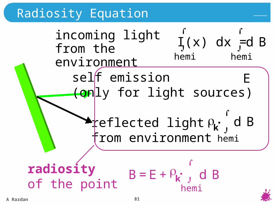
incoming light from the environment
self emission(only for light sources)
reflected lightfrom environment
B = E + k. d B
hemi
radiosityof the point
E
hemi
I(x) dx =
hemi
d B
A Razdan 82
Radiosity Equation
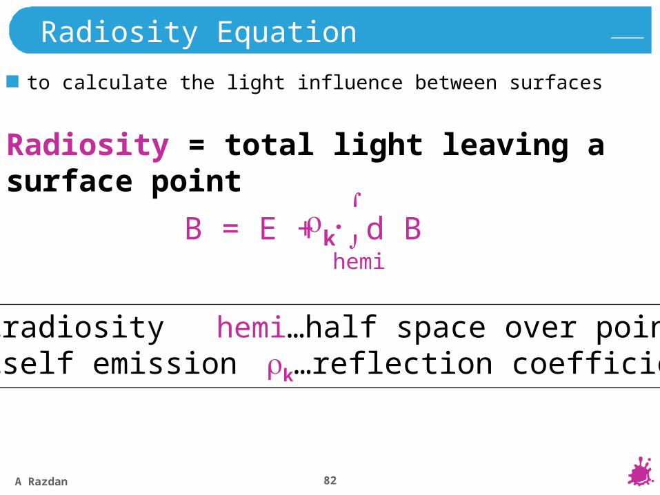
to calculate the light influence between surfaces
B = E + k. d B
hemi
Radiosity = total light leaving a surface point
B…radiosity hemi…half space over pointE…self emission k…reflection coefficient
A Razdan 83
Radiosity Properties
diffuse interreflections in a sceneradiant energy transfersconservation of energy, closed environmentssubdivision of sceneinto patches withconstant radiosity Bk
A Razdan 84
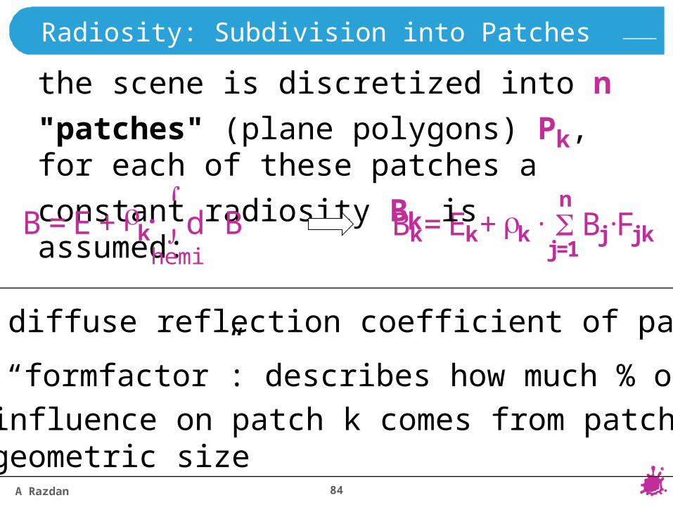
Radiosity: Subdivision into Patches
Bk = Ek + k . Fjk.Bj
j=1
n
the scene is discretized into n "patches"
(plane polygons) Pk, for each of these
patches a constant radiosity Bk is assumed:
k diffuse reflection coefficient of patch k
Fjk “formfactor”: describes how much % of the
influence on patch k comes from patch j; geometric size
B = E + k. d B
hemi
A Razdan 85
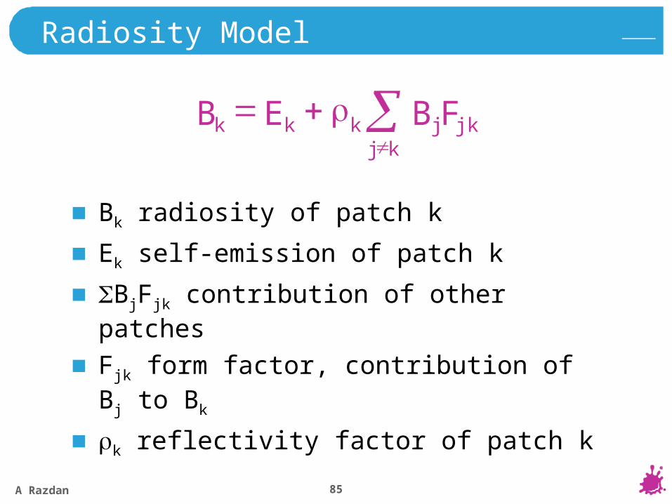
Radiosity Model
Bk radiosity of patch k
Ek self-emission of patch k
BjFjk contribution of other patches
Fjk form factor, contribution of Bj to Bk
k reflectivity factor of patch k
kj
j jkkkk B FEB

A Razdan 86
Radiosity Equation
solving the radiosity equation
kj
j jkkkk B FEB
kkj
j jkkk EB FB
nn2n1n
2
1
E
EE
B
BB
FF
FFFF
...
...
...
...
2
1
2
1
nn
n2122
n1211
11
......
......
A Razdan 87
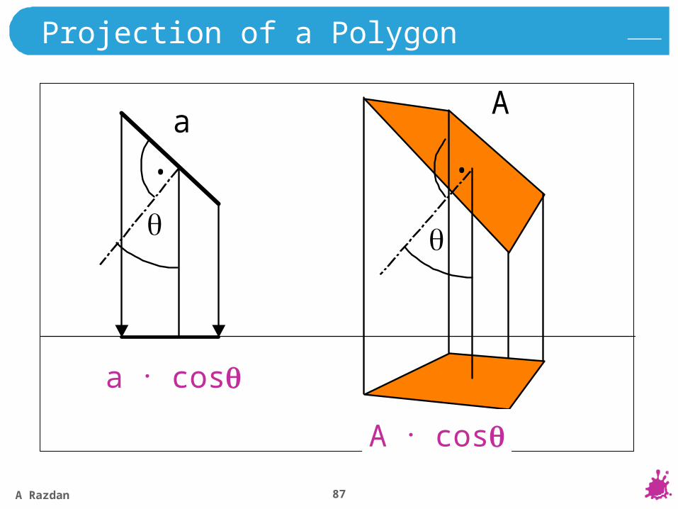
Projection of a Polygon
aA
. .
a·cos
A·cos
a . cos
A . cos
A Razdan 88
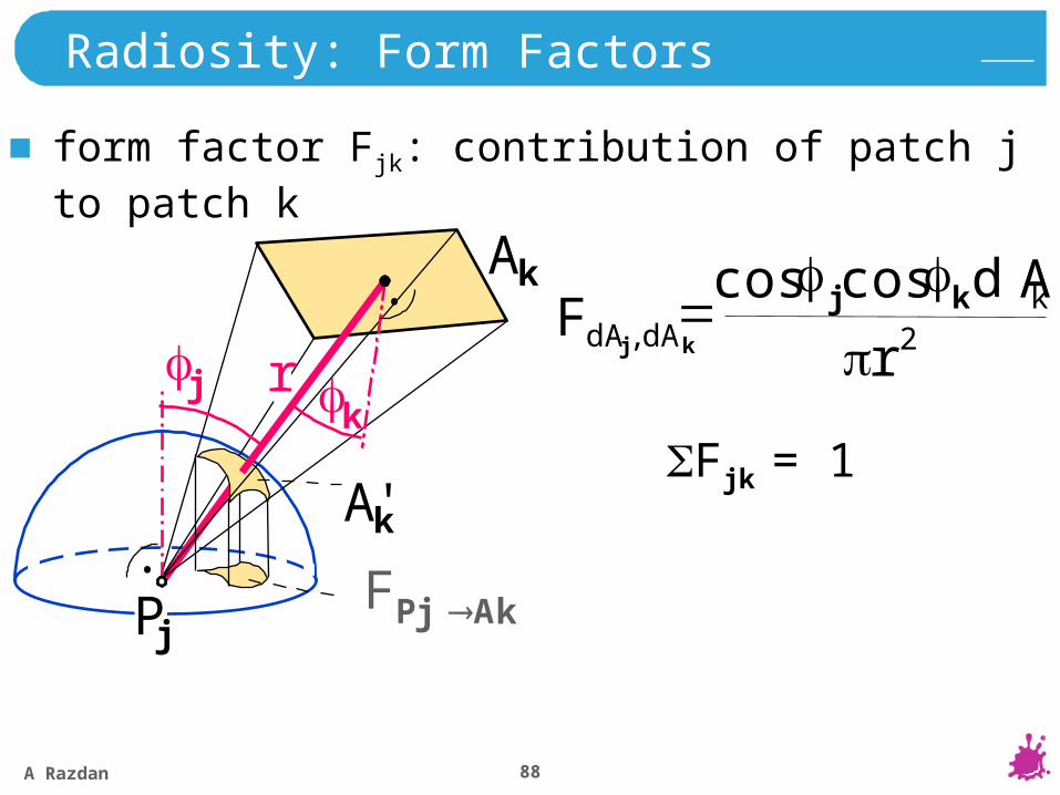
Radiosity: Form Factors
form factor Fjk: contribution of patch j to patch k
2r
Ak
cos kcos j
Ak
Ak'
Pj
.
j k
.
r
FP Aj k
Fjk = 1
,F dAdA kj d
A Razdan 89
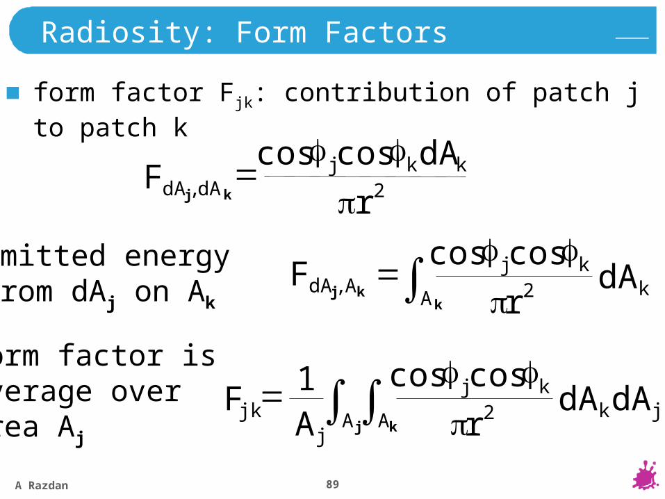
Radiosity: Form Factors
2,
coscos
r
dAF kkj
dAdA kj
form factor Fjk: contribution of patch j to patch k
kA k
kj dAr 2
coscos
,F AdA kj
emitted energyfrom dAj on Ak
j kA A jk
kj
jjk dAdA
rAF 2
coscos1
form factor isaverage overarea Aj
A Razdan 90
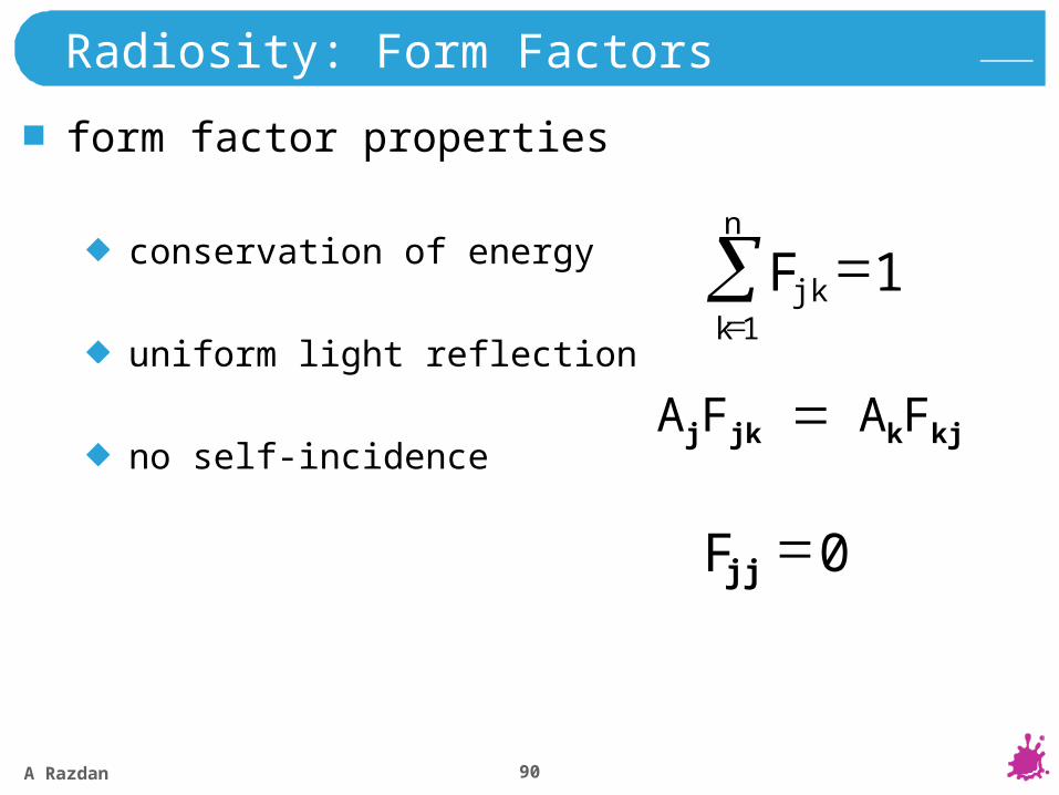
Radiosity: Form Factors
form factor properties
conservation of energy
uniform light reflection
no self-incidence
11
n
kjkF
0jjF
AjFjk AkFkj
A Razdan 91
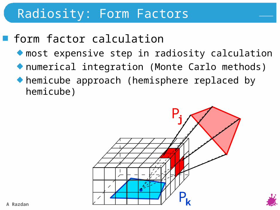
Radiosity: Form Factors
form factor calculationmost expensive step in radiosity calculation
numerical integration (Monte Carlo methods)
hemicube approach (hemisphere replaced by hemicube)
Pk
Pj
A Razdan 92
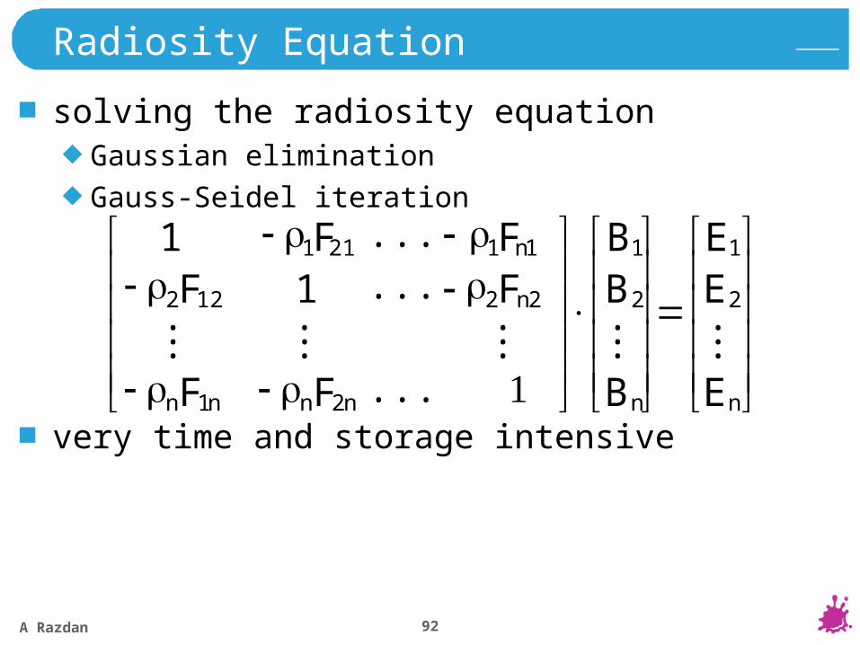
Radiosity Equation
solving the radiosity equationGaussian elimination
Gauss-Seidel iteration
very time and storage intensive
nn2n1n
2
1
E
EE
B
BB
FF
FFFF
...
...
...
...
2
1
2
1
nn
n2122
n1211
11
......
......
A Razdan 93
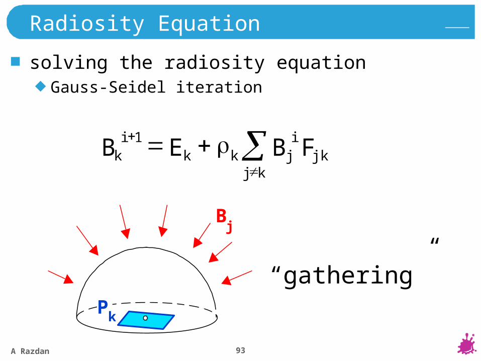
Radiosity Equation
solving the radiosity equationGauss-Seidel iteration
kj
ij jkkk
ik B FEB 1
Pk
Bj
“gathering”
A Razdan 94
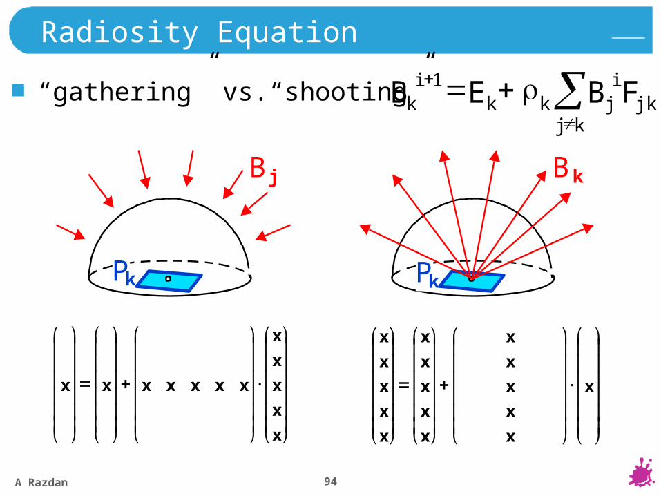
Radiosity Equation
“gathering” vs.“shooting”
kj
ij jkkk
ik B FEB 1
Pk
B j
Pk
B k
x
x
x
x
x
xxxxxxx
x
x
x
x
x
x
x
x
x
x
x
x
x
x
x
x
A Razdan 95
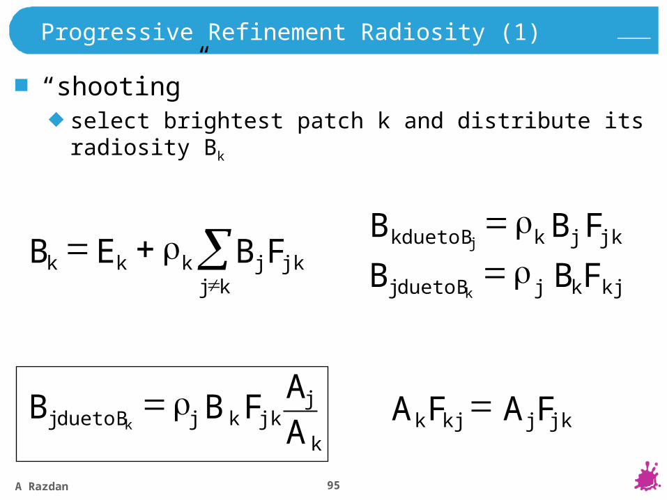
Progressive Refinement Radiosity (1)
“shooting”select brightest patch k and distribute its radiosity Bk
kj
j jkkkk B FEB j jkkk B FB j B todue
k kjjj B FB k B todue
kk
jjkjj B
AA
FB k B todue jkjkjk FAFA
A Razdan 96
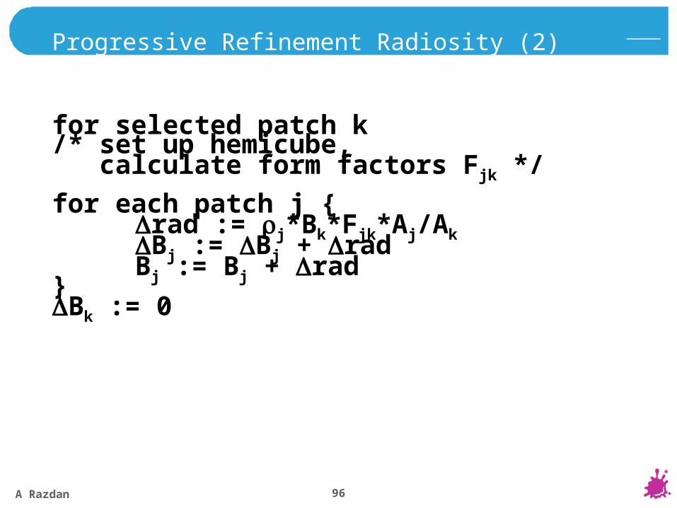
Progressive Refinement Radiosity (2)[one refinement step]
for selected patch k/* set up hemicube, calculate form factors Fjk */
for each patch j {rad := j*Bk*Fjk*Aj/AkBj := Bj + radBj := Bj + rad}
Bk := 0
A Razdan 97
Progressive Refinement Radiosity (3)
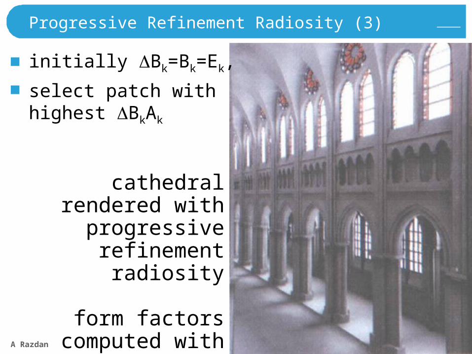
initially Bk=Bk=Ek,
select patch withhighest BkAk
cathedral rendered with progressive
refinement radiosity
form factors computed with ray-
tracing methods
A Razdan 98
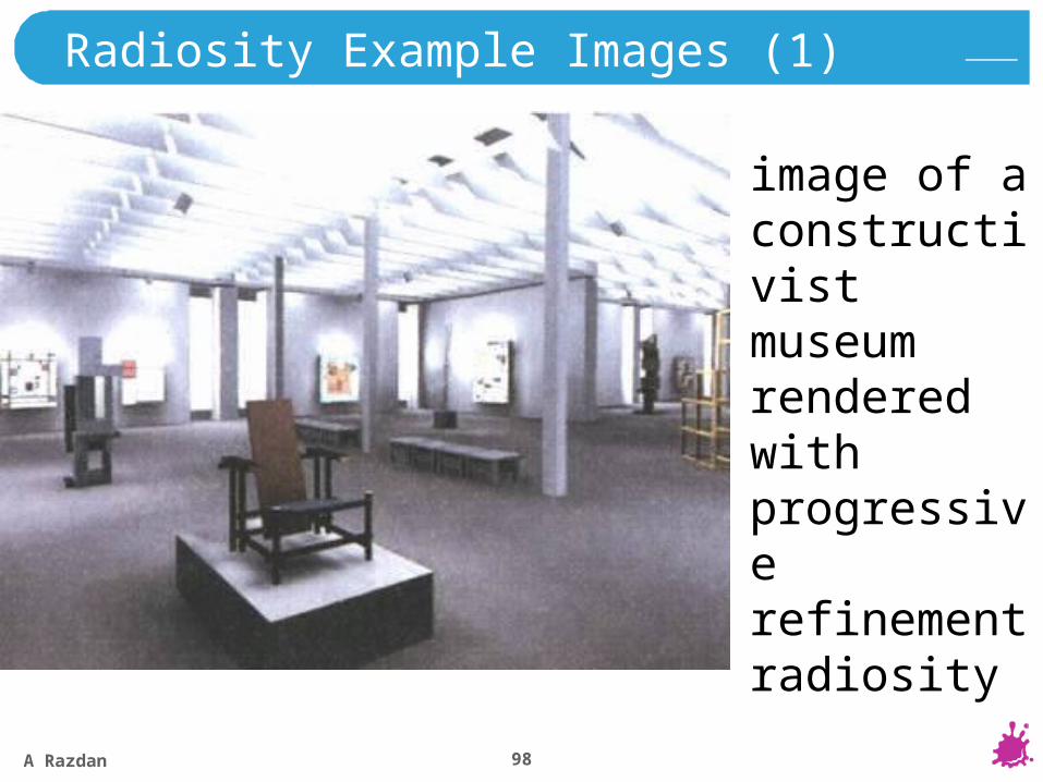
Radiosity Example Images (1)
image of a constructivist museum rendered with progressive refinement radiosity
A Razdan 99
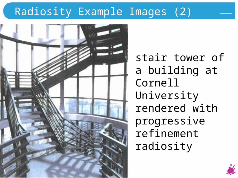
Radiosity Example Images (2)
stair tower of a building at Cornell University rendered with progressive refinement radiosity

A Razdan 100
Radiosity Example Images (3)
2 lighting schemes for an opera production:(left) day view (right) night view
A Razdan 101
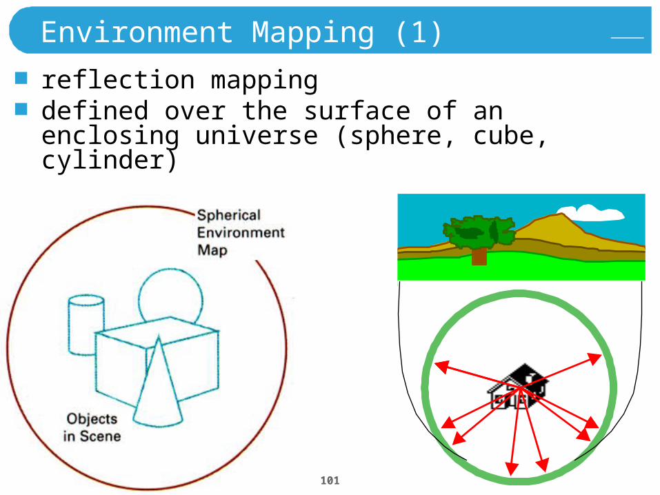
Environment Mapping (1)
reflection mappingdefined over the surface of an enclosing universe (sphere, cube, cylinder)
A Razdan 102
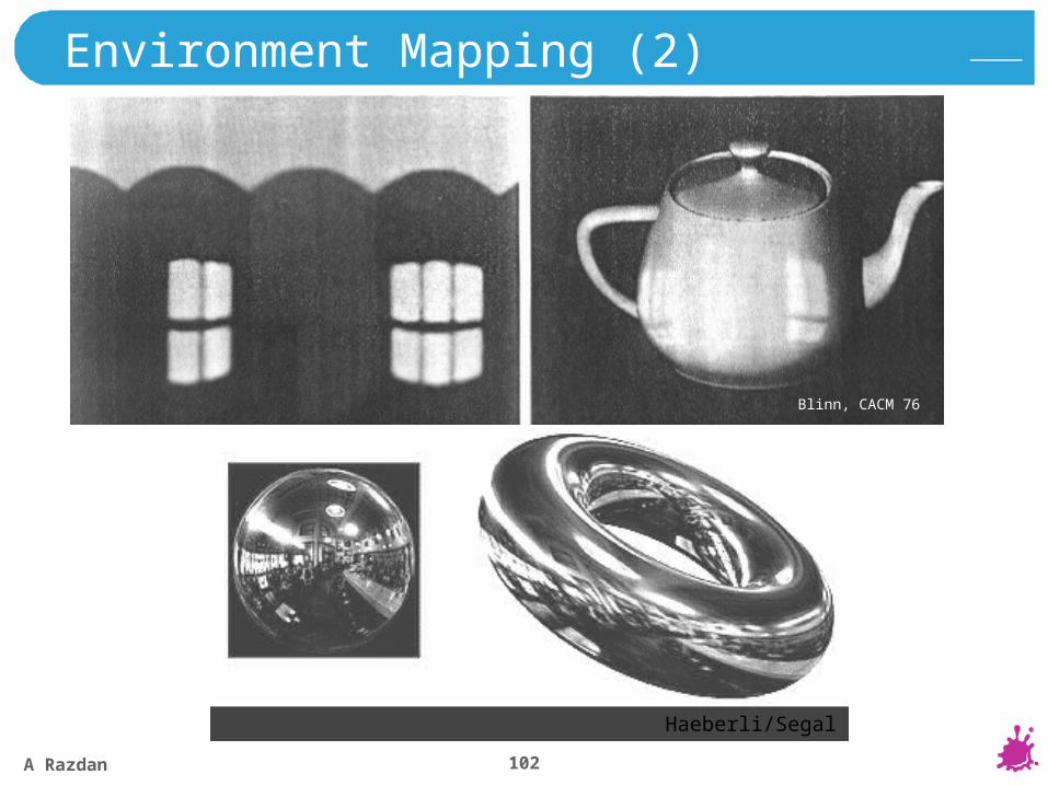
Blinn, CACM 76
Haeberli/Segal
Environment Mapping (2)
A Razdan 103
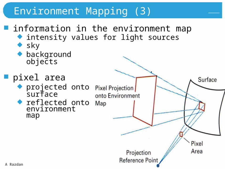
Environment Mapping (3)
information in the environment mapintensity values for light sourcesskybackgroundobjects
pixel areaprojected ontosurfacereflected onto environmentmap
A Razdan 104
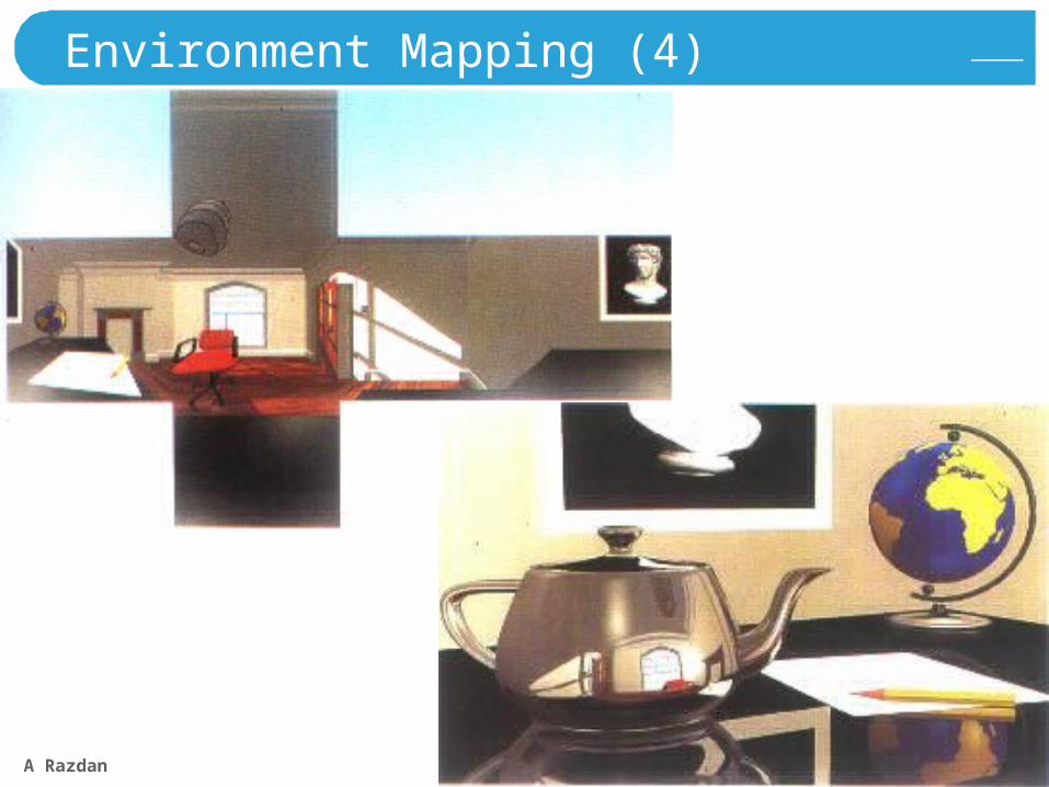
Environment Mapping (4)
A Razdan 105
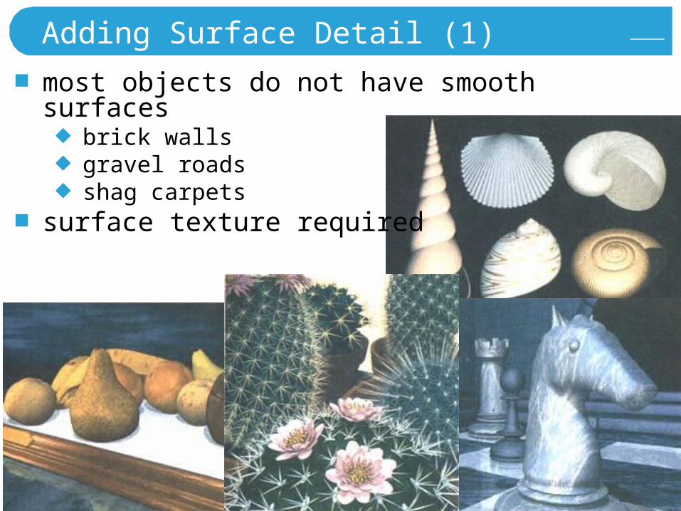
Adding Surface Detail (1)
most objects do not have smooth surfacesbrick wallsgravel roadsshag carpets
surface texture required
A Razdan 106
Adding Surface Detail (2)
modeling surface detail with polygonssmall polygon facets(e.g., checkerboard squares)
facets overlaid on surface polygon (parent)
parent surface used for visibility calculations
facets used for illumination calculations
impractical for intricate surface structure
A Razdan 107
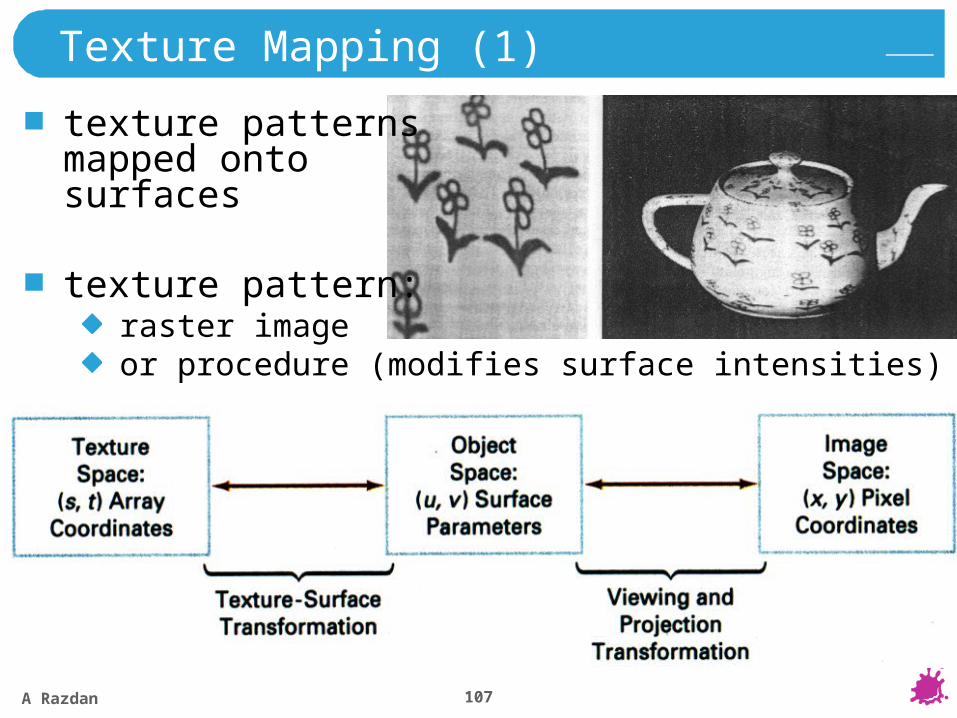
Texture Mapping (1)
texture patternsmapped ontosurfaces
texture pattern:raster imageor procedure (modifies surface intensities)
A Razdan 108
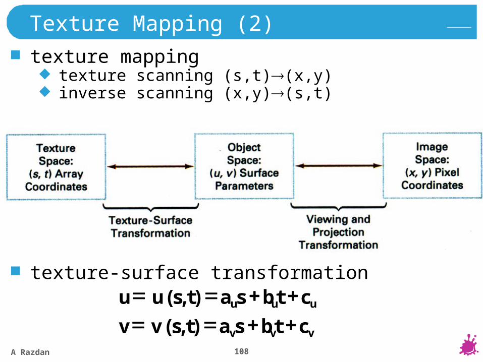
Texture Mapping (2)
texture mappingtexture scanning (s,t)(x,y)inverse scanning (x,y)(s,t)
texture-surface transformation
vvv
uuu
ctbsatsvv
ctbsatsuu
),(
),(
A Razdan 109
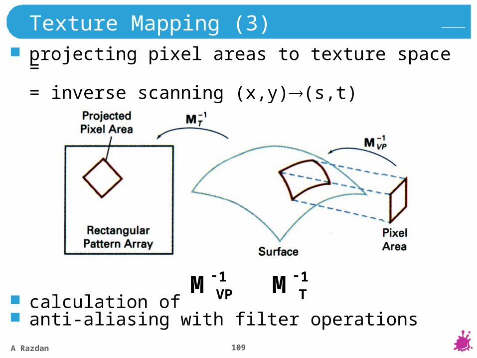
Texture Mapping (3)
projecting pixel areas to texture space =
= inverse scanning (x,y)(s,t)
calculation ofanti-aliasing with filter operations
VPM 1-TM 1-
A Razdan 110
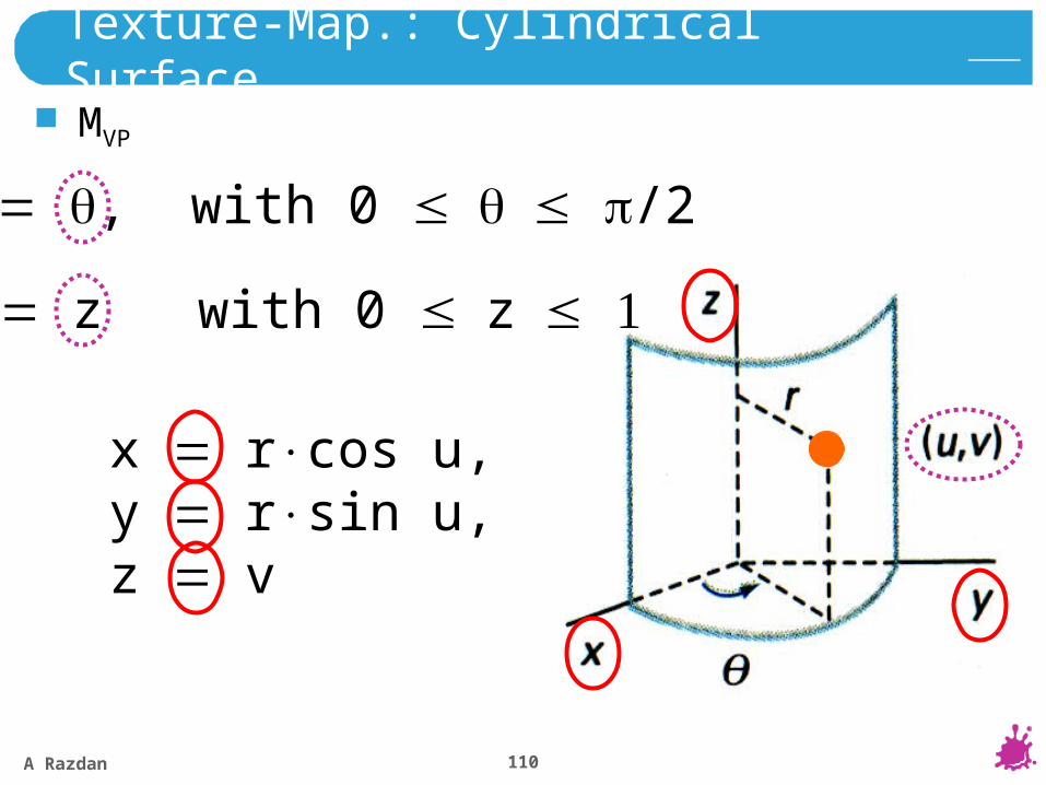
Texture-Map.: Cylindrical Surface
u , with 0 /2
v z with 0 z
x rcos u,y rsin u,z v
MVP

A Razdan 111
M-1VP
pixel surface point (x,y,z)(x,y,z) (u,v):
Texture-Map.: Cylindrical Surface
M-1T
tvsu ,2/
zvxyu ),/(tan 1
vtus ,/2
MT
A Razdan 112
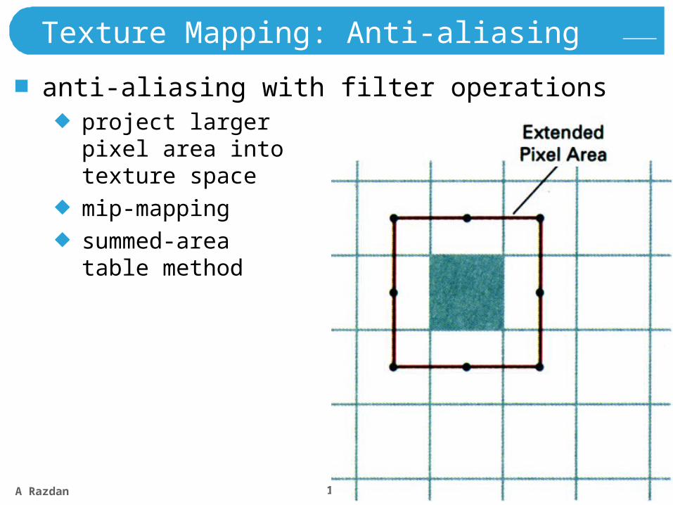
Texture Mapping: Anti-aliasing
anti-aliasing with filter operationsproject largerpixel area intotexture space
mip-mapping
summed-areatable method
A Razdan 113
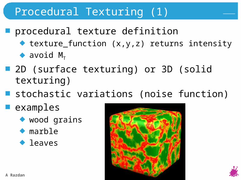
Procedural Texturing (1)
procedural texture definitiontexture_function (x,y,z) returns intensity
avoid MT
2D (surface texturing) or 3D (solid texturing)
stochastic variations (noise function)
exampleswood grains
marble
leaves
Copyright Alias|Wavefront
A Razdan 114
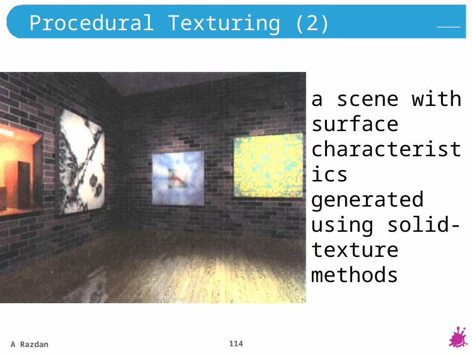
Procedural Texturing (2)
a scene with surface characteristics generated using solid-texture methods
A Razdan 115
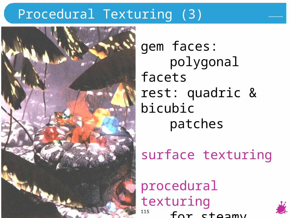
Procedural Texturing (3)
gem faces:polygonal facets
rest: quadric & bicubic patches
surface texturing
procedural texturingfor steamy jungle atmosphere
A Razdan 116
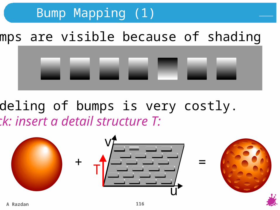
Bump Mapping (1)
bumps are visible because of shading
modeling of bumps is very costly.trick: insert a detail structure T:
T
v
u
+ =
A Razdan 117
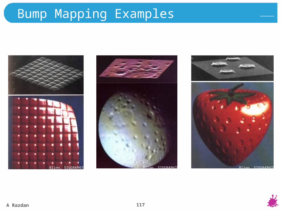
Bump Mapping Examples
Blinn, SIGGRAPH78 Blinn, SIGGRAPH78 Blinn, SIGGRAPH78
A Razdan 118
Perlin, SIGGRAPH85
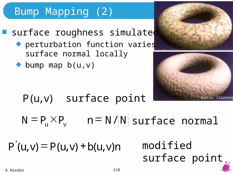
Bump Mapping (2)
surface roughness simulatedperturbation function variessurface normal locally
bump map b(u,v)
),( vuP
vu PPN NNn /
surface point
surface normal
nvubvuPvuP ),(),(),( modified surface point
A Razdan 119
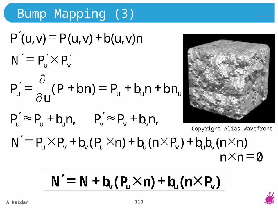
Bump Mapping (3)
nvubvuPvuP ),(),(),(
vu PPN
uuuu bnnbPbnPu
P
)(
, , nbPPnbPP vvvuuu
)()()( nnbbPnbnPbPPN vuvuuvvu
0nn
)()( vuuv PnbnPbNN
Copyright Alias|Wavefront

A Razdan 120
Bump Mapping (4)
bump map b(u,v) defined as raster imagebu, bv: approximated with finite differences
Copyright Alias|Wavefront
A Razdan 121
Displacement Mapping
“Correct version of bump mapping”Surface points are moved from their original positionOutline of object changesMuch harder to implement than bump mapping
Rare in practice
Latest hardware partially supports it
A Razdan 122
Combination of Mapping Methods
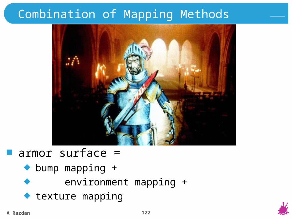
armor surface =bump mapping +
environment mapping +
texture mapping


![Pt1286633[Anshuman Arya] Final Pptmaking of Piston](https://img.dokumen.tips/doc/110x75/563dbab7550346aa9aa776ea/pt1286633anshuman-arya-final-pptmaking-of-piston.jpg)


