Embed Size (px)
Citation preview
CSCI 5828: Foundations ofSoftware Engineering
Lecture 5 and 6: Modeling the Process and Life CycleSlides created by Pfleeger and Atlee for the SE textbook
Some modifications to the original slides have been madeby Ken Anderson for clarity of presentation
01/29/2008 — 01/31/2008
ISBN 0-13-146913-4Prentice-Hall, 2006
Chapter 2
Modeling theProcess and LifeCycle
Copyright 2006 Pearson/Prentice Hall. All rights reserved.
Pfleeger and Atlee, Software Engineering: Theory and Practice Page 2.3© 2006 Pearson/Prentice Hall
Contents
2.1 The Meaning of Process2.2 Software Process Models2.3 Tools and Techniques for Process Modeling2.4 Practical Process Modeling2.5 Information System Example2.6 Real Time Example2.7 What this Chapter Means for You
Pfleeger and Atlee, Software Engineering: Theory and Practice Page 2.4© 2006 Pearson/Prentice Hall
Chapter 2 Objectives
• Discuss the definition of “process” or “life cycle”• Discuss standard terminology:
– Software dev. products, processes, and resources• Present several software life cycles• Cover tools and techniques for process modeling
Pfleeger and Atlee, Software Engineering: Theory and Practice Page 2.5© 2006 Pearson/Prentice Hall
2.1 The Meaning of Process
• process:– a series of steps involving activities, constrains, and
resources that produce an intended ouput of some kind• A process involves a set of tools and techniques
Pfleeger and Atlee, Software Engineering: Theory and Practice Page 2.6© 2006 Pearson/Prentice Hall
2.1 The Meaning of ProcessProcess Characteristics
• Prescribes all major process activities• Uses resources, subject to set of constraints
– (such as a schedule or a budget)– Constraints may apply to an activity, resource or product
• Produces intermediate and final products• May be composed of subprocesses with hierarchy or links• Each process activity has entry and exit criteria• Activities are organized in sequence, so timing is clear
• Each process has guiding principles, including the goalsof each activity
Pfleeger and Atlee, Software Engineering: Theory and Practice Page 2.7© 2006 Pearson/Prentice Hall
2.1 The Meaning of ProcessThe Importance of Processes
• Impose consistency and structure on a set ofactivities– especially across projects in a single organization– or two or more projects performed by the same team
• Aids engineers in understanding, controlling, andimproving the activities within the process
• Allows engineers to capture/measure ourexperiences and use them to improve futureperformance
Pfleeger and Atlee, Software Engineering: Theory and Practice Page 2.8© 2006 Pearson/Prentice Hall
2.2 Software Process ModelsReasons for Modeling a Process
• To form a common understanding across differentstakeholders
• To find inconsistencies, redundancies, omissions
• To find and evaluate appropriate activities forreaching process goals
• To tailor a general process for a particularsituation in which it will be used
Pfleeger and Atlee, Software Engineering: Theory and Practice Page 2.9© 2006 Pearson/Prentice Hall
2.2 Software Process ModelsSoftware Life Cycle
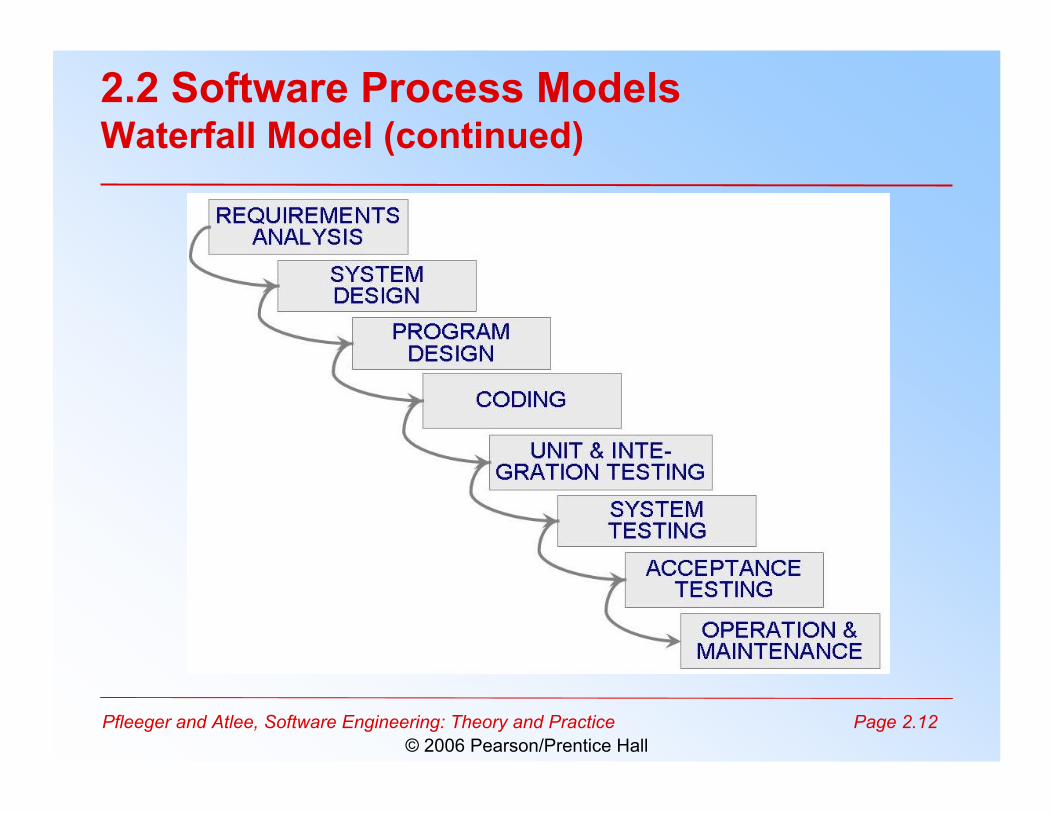
• When a process involves building software, theprocess may be referred to as software life cycle– Requirements analysis and definition– System (architecture) design– Program (detailed/procedural) design– Writing programs (coding/implementation)– Testing: unit, integration, system– System delivery (deployment)
– Maintenance
Pfleeger and Atlee, Software Engineering: Theory and Practice Page 2.10© 2006 Pearson/Prentice Hall
2.2 Software Process ModelsSoftware Development Process Models
• Waterfall model• V model• Prototyping model• Operational specification• Transformational model• Phased development: increments and iterations• Spiral model• Agile methods
Pfleeger and Atlee, Software Engineering: Theory and Practice Page 2.11© 2006 Pearson/Prentice Hall
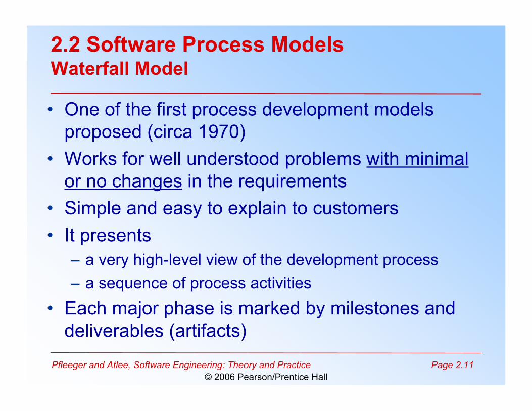
2.2 Software Process ModelsWaterfall Model
• One of the first process development modelsproposed (circa 1970)
• Works for well understood problems with minimalor no changes in the requirements
• Simple and easy to explain to customers• It presents
– a very high-level view of the development process– a sequence of process activities
• Each major phase is marked by milestones anddeliverables (artifacts)
Pfleeger and Atlee, Software Engineering: Theory and Practice Page 2.12© 2006 Pearson/Prentice Hall
2.2 Software Process ModelsWaterfall Model (continued)
Pfleeger and Atlee, Software Engineering: Theory and Practice Page 2.13© 2006 Pearson/Prentice Hall
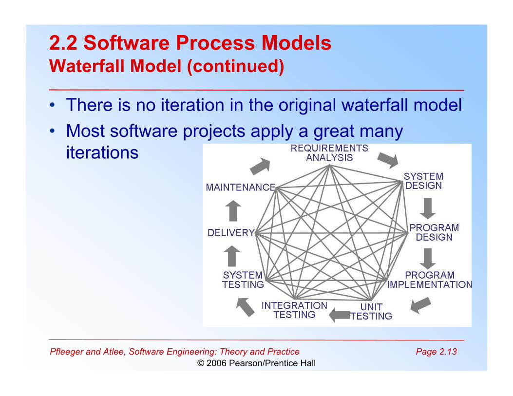
2.2 Software Process ModelsWaterfall Model (continued)
• There is no iteration in the original waterfall model• Most software projects apply a great many
iterations
Pfleeger and Atlee, Software Engineering: Theory and Practice Page 2.14© 2006 Pearson/Prentice Hall
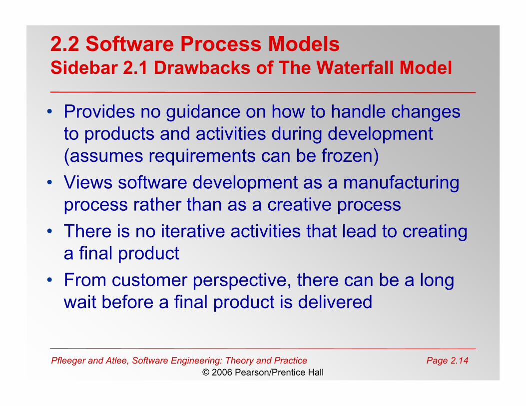
2.2 Software Process ModelsSidebar 2.1 Drawbacks of The Waterfall Model
• Provides no guidance on how to handle changesto products and activities during development(assumes requirements can be frozen)
• Views software development as a manufacturingprocess rather than as a creative process
• There is no iterative activities that lead to creatinga final product
• From customer perspective, there can be a longwait before a final product is delivered
Pfleeger and Atlee, Software Engineering: Theory and Practice Page 2.15© 2006 Pearson/Prentice Hall
2.2 Software Process ModelsWaterfall Model with Prototype
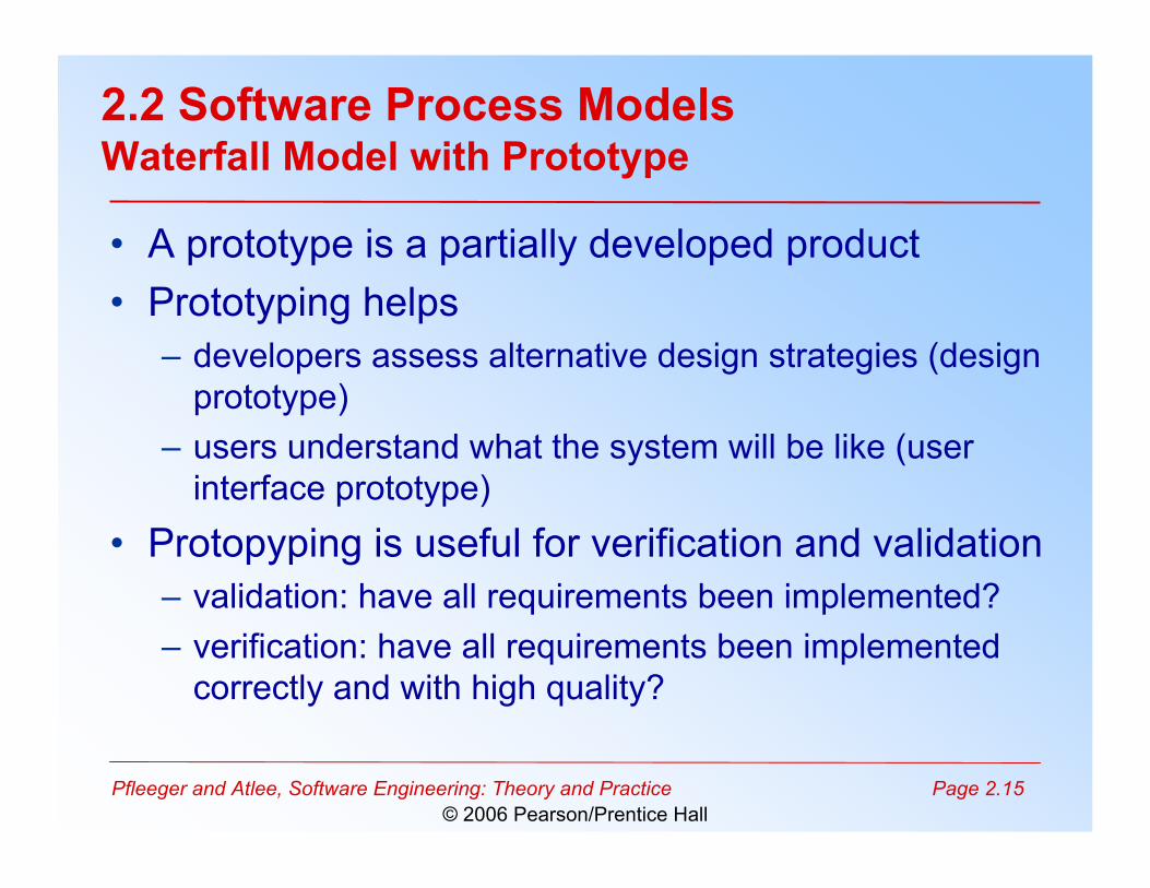
• A prototype is a partially developed product• Prototyping helps
– developers assess alternative design strategies (designprototype)
– users understand what the system will be like (userinterface prototype)
• Protopyping is useful for verification and validation– validation: have all requirements been implemented?– verification: have all requirements been implemented
correctly and with high quality?
Pfleeger and Atlee, Software Engineering: Theory and Practice Page 2.16© 2006 Pearson/Prentice Hall
2.2 Software Process ModelsWaterfall Model with Prototype (continued)
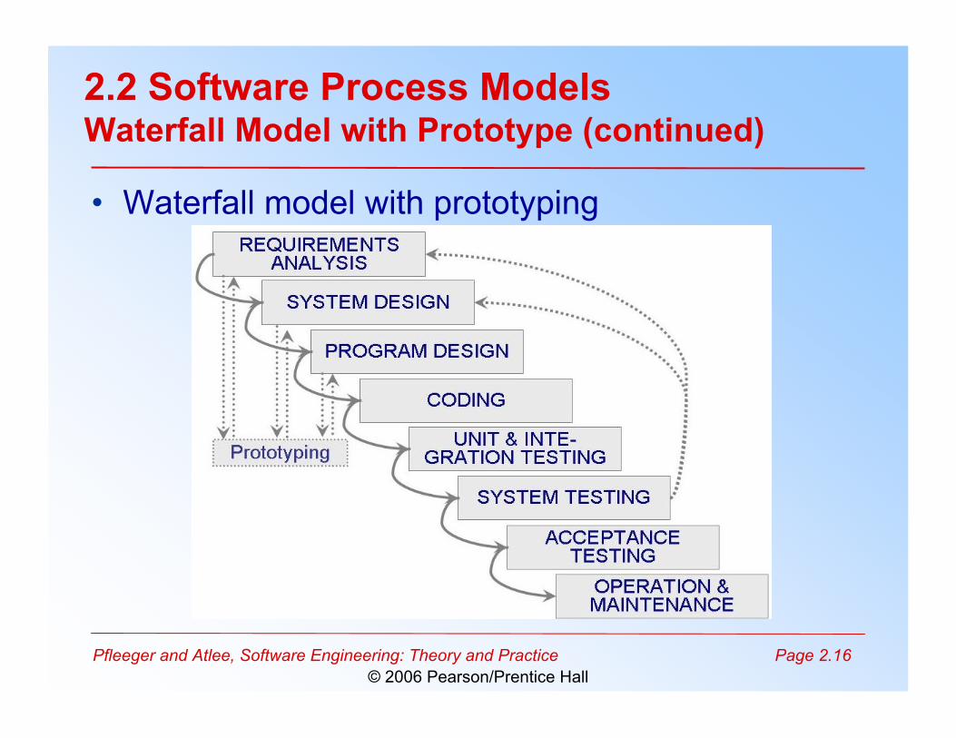
• Waterfall model with prototyping
Pfleeger and Atlee, Software Engineering: Theory and Practice Page 2.17© 2006 Pearson/Prentice Hall
2.2 Software Process ModelsV Model
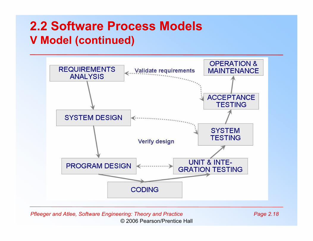
• A (slight) variation of the waterfall model• Uses unit testing to verify program design• Uses integration testing to verify architectural design• Uses acceptance testing to validate the requirements
• If problems are found during verification and validation,the “left side” of the V can be re-executed before testingon the “right side” is re-enacted
Pfleeger and Atlee, Software Engineering: Theory and Practice Page 2.18© 2006 Pearson/Prentice Hall
2.2 Software Process ModelsV Model (continued)
Pfleeger and Atlee, Software Engineering: Theory and Practice Page 2.19© 2006 Pearson/Prentice Hall
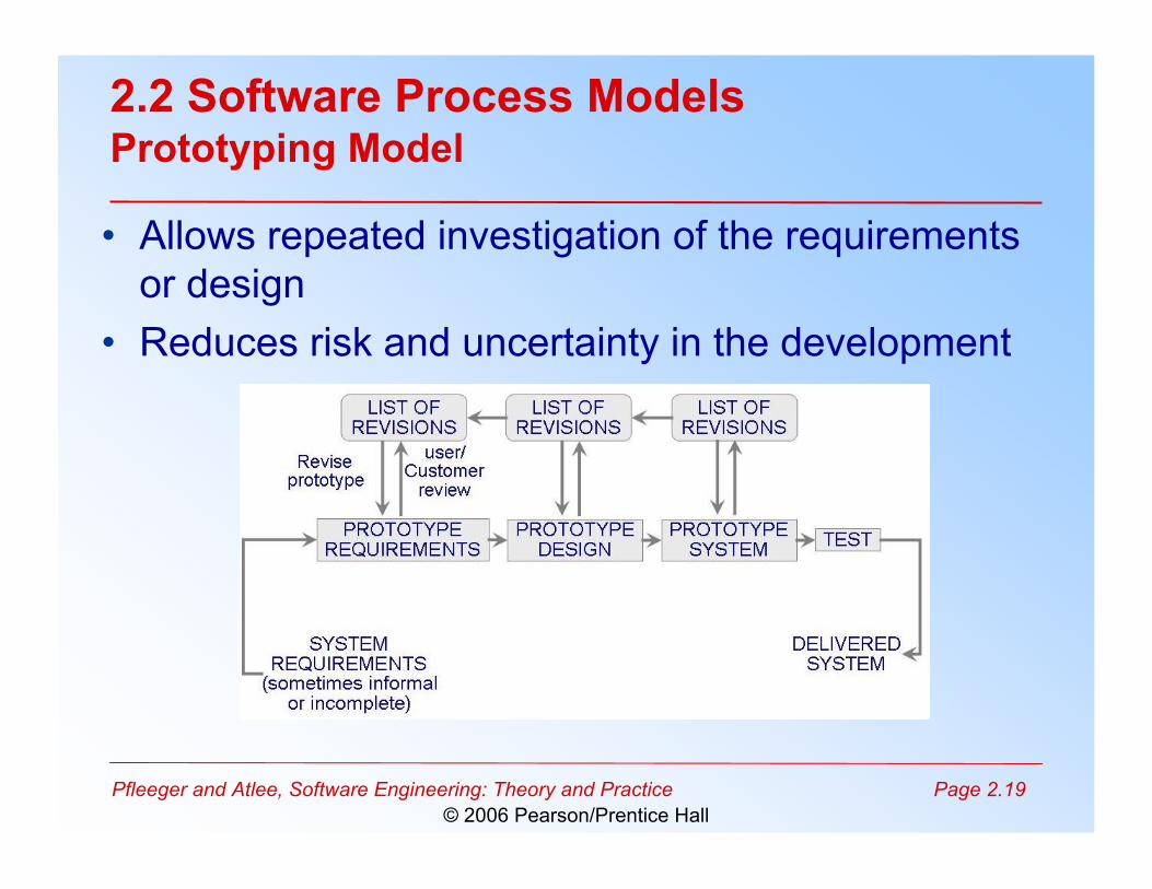
2.2 Software Process ModelsPrototyping Model
• Allows repeated investigation of the requirementsor design
• Reduces risk and uncertainty in the development
Pfleeger and Atlee, Software Engineering: Theory and Practice Page 2.20© 2006 Pearson/Prentice Hall
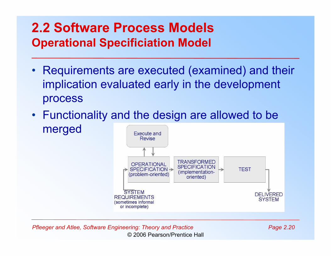
2.2 Software Process ModelsOperational Specificiation Model
• Requirements are executed (examined) and theirimplication evaluated early in the developmentprocess
• Functionality and the design are allowed to bemerged
Pfleeger and Atlee, Software Engineering: Theory and Practice Page 2.21© 2006 Pearson/Prentice Hall
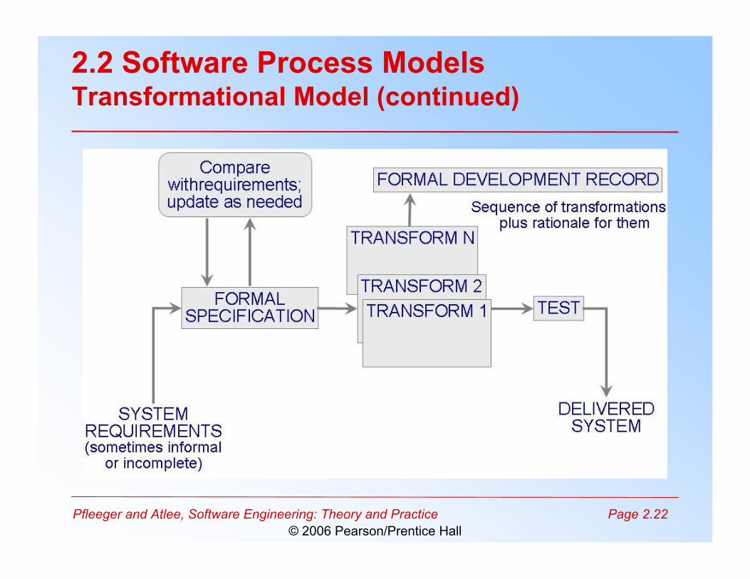
2.2 Software Process ModelsTransformational Model
• Fewer major development steps• Applies a series of transformations to change a
specification into a deliverable system– Change data representation– Select algorithms– Optimize– Compile
• Relies on formalism by requiring an initial, formalspecification (to allow transformations)
Pfleeger and Atlee, Software Engineering: Theory and Practice Page 2.22© 2006 Pearson/Prentice Hall
2.2 Software Process ModelsTransformational Model (continued)
Pfleeger and Atlee, Software Engineering: Theory and Practice Page 2.23© 2006 Pearson/Prentice Hall
2.2 Software Process ModelsPhased Development: Increments and Iterations
• Shorter cycle time• System delivered in pieces
– enables customers to have some functionality while therest is being developed
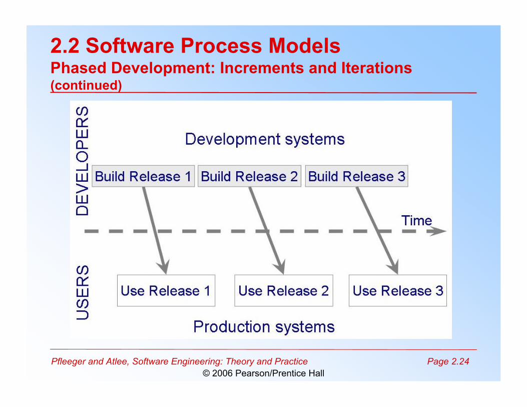
• Allows two systems functioning in parallel– the production system (release n): currently being used– the development system (release n+1): the next
version
Pfleeger and Atlee, Software Engineering: Theory and Practice Page 2.24© 2006 Pearson/Prentice Hall
2.2 Software Process ModelsPhased Development: Increments and Iterations(continued)
Pfleeger and Atlee, Software Engineering: Theory and Practice Page 2.25© 2006 Pearson/Prentice Hall
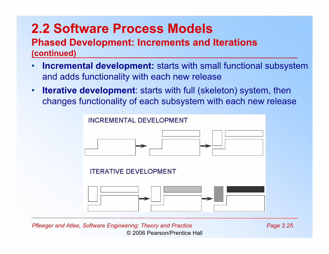
2.2 Software Process ModelsPhased Development: Increments and Iterations(continued)• Incremental development: starts with small functional subsystem
and adds functionality with each new release• Iterative development: starts with full (skeleton) system, then
changes functionality of each subsystem with each new release
Pfleeger and Atlee, Software Engineering: Theory and Practice Page 2.26© 2006 Pearson/Prentice Hall
2.2 Software Process ModelsPhased Development: Increments and Iterations(continued)
• Phased development is desirable for severalreasons– Training can begin early, even though some functions are
missing
– Frequent releases allow developers to fix unanticipatedproblems globally and quickly
– The development team can focus on different areas ofexpertise with different releases
Pfleeger and Atlee, Software Engineering: Theory and Practice Page 2.27© 2006 Pearson/Prentice Hall
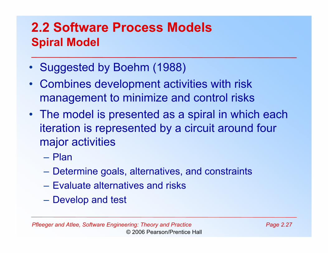
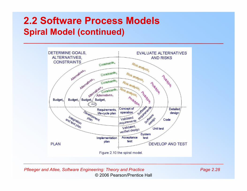
2.2 Software Process ModelsSpiral Model
• Suggested by Boehm (1988)• Combines development activities with risk
management to minimize and control risks• The model is presented as a spiral in which each
iteration is represented by a circuit around fourmajor activities– Plan– Determine goals, alternatives, and constraints– Evaluate alternatives and risks– Develop and test
Pfleeger and Atlee, Software Engineering: Theory and Practice Page 2.28© 2006 Pearson/Prentice Hall
2.2 Software Process ModelsSpiral Model (continued)
Pfleeger and Atlee, Software Engineering: Theory and Practice Page 2.29© 2006 Pearson/Prentice Hall
2.2 Software Process ModelsAgile Methods• Emphasis on flexibility in producing software quickly• Agile manifesto
– Value individuals and interactions over process and tools
– Prefer to invest time in producing working software rather than inproducing comprehensive documentation
– Focus on customer collaboration rather than contract negotiation
– Concentrate on responding to change rather than on creating a planand then following it
Pfleeger and Atlee, Software Engineering: Theory and Practice Page 2.30© 2006 Pearson/Prentice Hall
2.2 Software Process ModelsAgile Methods: Examples of Agile Process
• Extreme programming (XP)• Crystal: a collection of approaches based on the
notion that every project needs a unique set ofpolicies and conventions
• Scrum: 30-day iterations; multiple self-organizingteams; daily “scrum” coordination
• Adaptive software development (ASD)
Pfleeger and Atlee, Software Engineering: Theory and Practice Page 2.31© 2006 Pearson/Prentice Hall
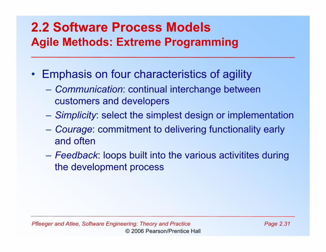
2.2 Software Process ModelsAgile Methods: Extreme Programming
• Emphasis on four characteristics of agility– Communication: continual interchange between
customers and developers– Simplicity: select the simplest design or implementation– Courage: commitment to delivering functionality early
and often– Feedback: loops built into the various activitites during
the development process
Pfleeger and Atlee, Software Engineering: Theory and Practice Page 2.32© 2006 Pearson/Prentice Hall
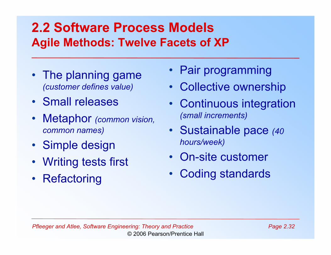
2.2 Software Process ModelsAgile Methods: Twelve Facets of XP
• The planning game(customer defines value)
• Small releases• Metaphor (common vision,
common names)
• Simple design• Writing tests first• Refactoring
• Pair programming• Collective ownership• Continuous integration
(small increments)
• Sustainable pace (40hours/week)
• On-site customer• Coding standards
Pfleeger and Atlee, Software Engineering: Theory and Practice Page 2.33© 2006 Pearson/Prentice Hall
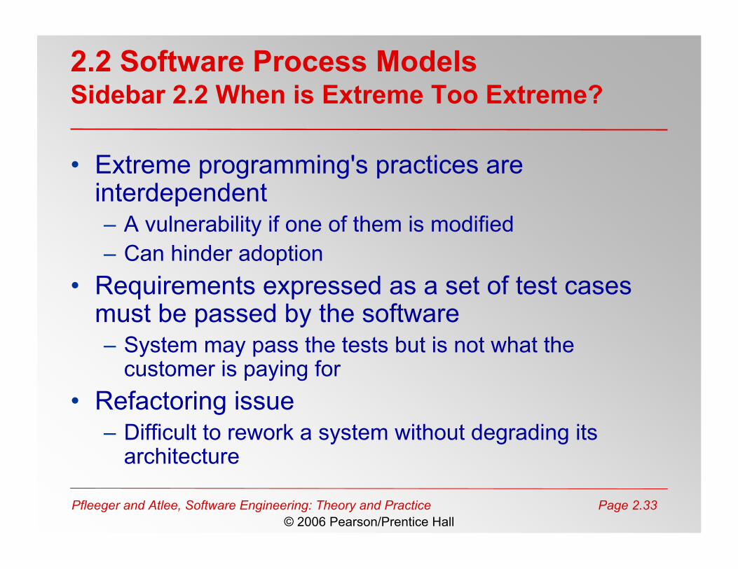
2.2 Software Process ModelsSidebar 2.2 When is Extreme Too Extreme?
• Extreme programming's practices areinterdependent– A vulnerability if one of them is modified– Can hinder adoption
• Requirements expressed as a set of test casesmust be passed by the software– System may pass the tests but is not what the
customer is paying for• Refactoring issue
– Difficult to rework a system without degrading itsarchitecture
Pfleeger and Atlee, Software Engineering: Theory and Practice Page 2.34© 2006 Pearson/Prentice Hall
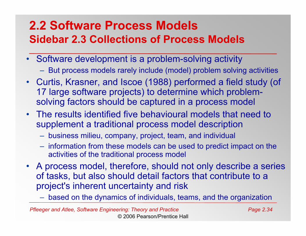
2.2 Software Process ModelsSidebar 2.3 Collections of Process Models
• Software development is a problem-solving activity– But process models rarely include (model) problem solving activities
• Curtis, Krasner, and Iscoe (1988) performed a field study (of17 large software projects) to determine which problem-solving factors should be captured in a process model
• The results identified five behavioural models that need tosupplement a traditional process model description– business milieu, company, project, team, and individual– information from these models can be used to predict impact on the
activities of the traditional process model• A process model, therefore, should not only describe a series
of tasks, but also should detail factors that contribute to aproject's inherent uncertainty and risk– based on the dynamics of individuals, teams, and the organization
Pfleeger and Atlee, Software Engineering: Theory and Practice Page 2.35© 2006 Pearson/Prentice Hall
• The notation used to document a process modeldepends on what we want to capture in the model– text can be used to capture a process as functions– graphics can be used to capture a process as “boxes
and arrows”– A combination can link diagrams to supplemental info
• The two major types of models– Static models: depict the process, showing how input is
transformed into output– Dynamic models: enact the process, enabling analysis
2.3 Process Modeling: Tools and Techniques
Pfleeger and Atlee, Software Engineering: Theory and Practice Page 2.36© 2006 Pearson/Prentice Hall
• Lai Notation: Not a lot of detail in the textbook– So, I went hunting for the paper that it was based on– I found it at the following URL (!)
• http://stinet.dtic.mil/cgi-bin/GetTRDoc?AD=ADA262314&Location=U2&doc=GetTRDoc.pdf
– The original paper is 105 pages long and goes into lotsof detail that I can’t cover here
– But, this should give you an idea for the amount ofwork it takes to create a process modeling notation
2.3 Tools and Techniques for Process ModelingStatic Modeling: Lai Notation
Pfleeger and Atlee, Software Engineering: Theory and Practice Page 2.37© 2006 Pearson/Prentice Hall
• Seven types of process elements– Activity: a task in the process, augmented with meta
information– Sequence: the order of activities– Process model: a particular view of the activities– Resource: A necessary item, tool, or person– Control: An external influence over process enactment– Policy: A high-level constraint– Organization: A mapping of logical roles to physical
groups• Several supporting templates, e.g., an Artifact
Definition Template
2.3 Tools and Techniques for Process ModelingStatic Modeling: Lai Notation
Pfleeger and Atlee, Software Engineering: Theory and Practice Page 2.38© 2006 Pearson/Prentice Hall
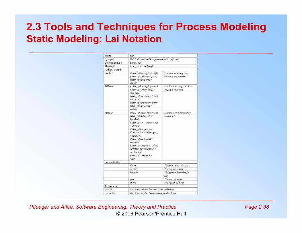
Name Car
Synopsis This is the artifact that represents a class of cars.
Complexity type Composite
Data type (car_c, user -defined)
Artifact -state list
parked ((state_of(car.engine) = off)
(state_of(car.gear) = park)
(state_of(car.speed) =
stand))
Car is not moving, and
engine is not running.
initiated ((state_of(car.engine) = on)
(state_of(car.key_hole) =
has-key)
(state_of(car -driver(car.))
= in -car)
(state_of(car.gear) = drive)
(state_of(car.speed) =
stand))
Car is not moving, but the
engine is run ning
moving ((state_of(car.engine) = on)
(state_of(car.keyhole) =
has-key)
(state_of(car -driver(car.))
= driving)
((state_of(car.gear) =
drive) or (state_of(car.gear)
= reverse))
((state_of(car.speed) =
stand) or
(state_of(car.speed) = slow)
or (state_of( car.speed) =
medium) or
(state_of(car.speed) =
high))
Car is moving forward or
backward.
Sub-artifact list
doors The four doors of a car.
engine The engine of a car.
keyhole The ignition keyhole of a
car.
gear The gear of a car.
speed The speed of a car.
Relations list
car-key This is the relation between a car and a key.
car-driver This is the relation between a car and a driver.
2.3 Tools and Techniques for Process ModelingStatic Modeling: Lai Notation
Pfleeger and Atlee, Software Engineering: Theory and Practice Page 2.39© 2006 Pearson/Prentice Hall
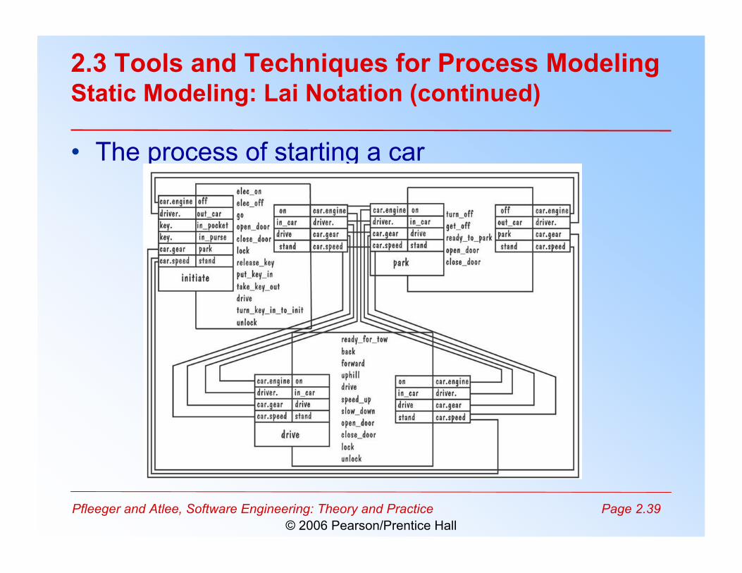
2.3 Tools and Techniques for Process ModelingStatic Modeling: Lai Notation (continued)
• The process of starting a car
Pfleeger and Atlee, Software Engineering: Theory and Practice Page 2.40© 2006 Pearson/Prentice Hall
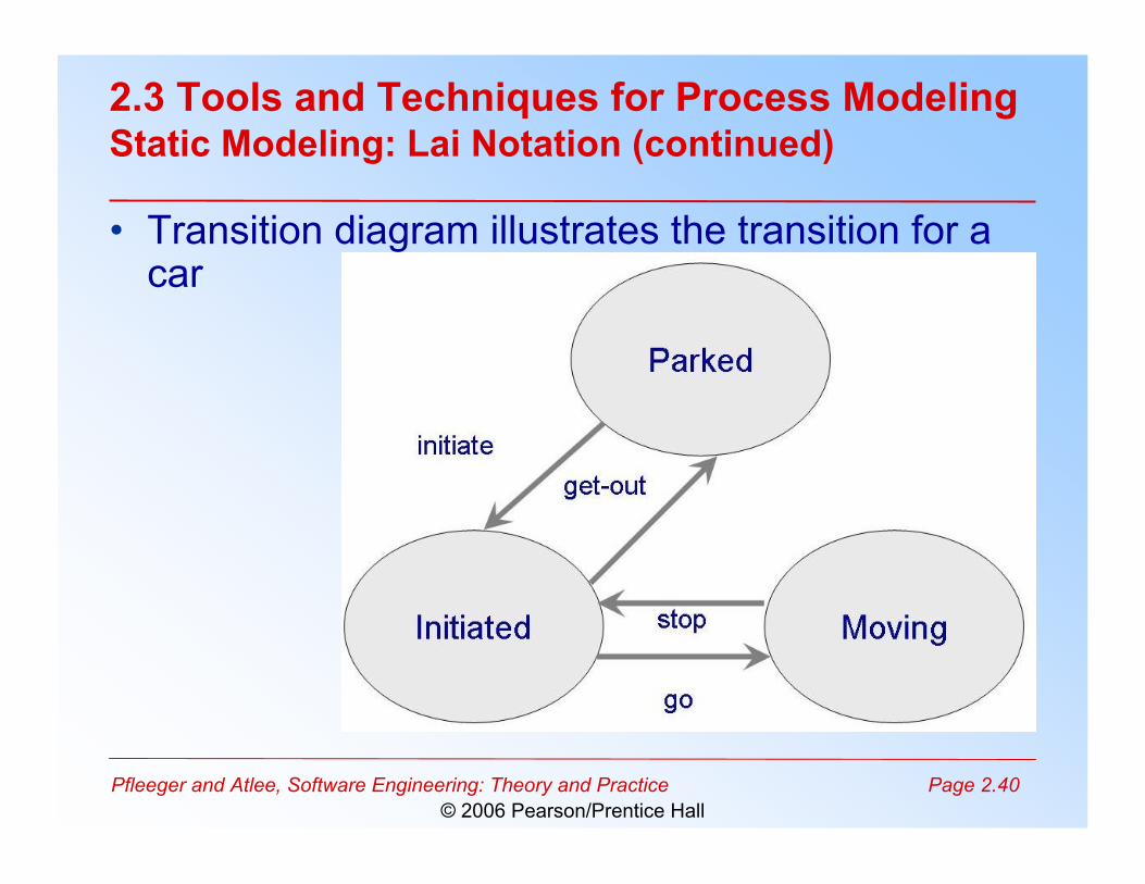
2.3 Tools and Techniques for Process ModelingStatic Modeling: Lai Notation (continued)
• Transition diagram illustrates the transition for acar
Pfleeger and Atlee, Software Engineering: Theory and Practice Page 2.41© 2006 Pearson/Prentice Hall
• Enables enaction of process to see what happensto resources and artifacts as activities occur
• Simulate alternatives and make changes toimprove the process
• Example: systems dynamics model
2.3 Tools and Techniques for Process ModelingDynamic Modeling
Pfleeger and Atlee, Software Engineering: Theory and Practice Page 2.42© 2006 Pearson/Prentice Hall
• Introduced by Forrester in the 1950's• Abdel-Hamid and Madnick applied it to software
development• One way to understand system dynamics is by
exploring how software development processaffects productivity
2.3 Tools and Techniques for Process ModelingDynamic Modeling: System Dynamics
Pfleeger and Atlee, Software Engineering: Theory and Practice Page 2.43© 2006 Pearson/Prentice Hall
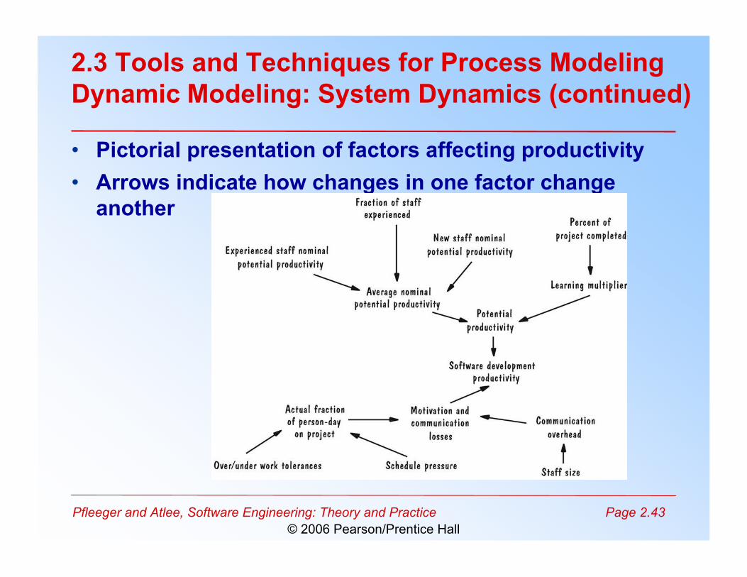
2.3 Tools and Techniques for Process ModelingDynamic Modeling: System Dynamics (continued)
• Pictorial presentation of factors affecting productivity• Arrows indicate how changes in one factor change
another
Pfleeger and Atlee, Software Engineering: Theory and Practice Page 2.44© 2006 Pearson/Prentice Hall
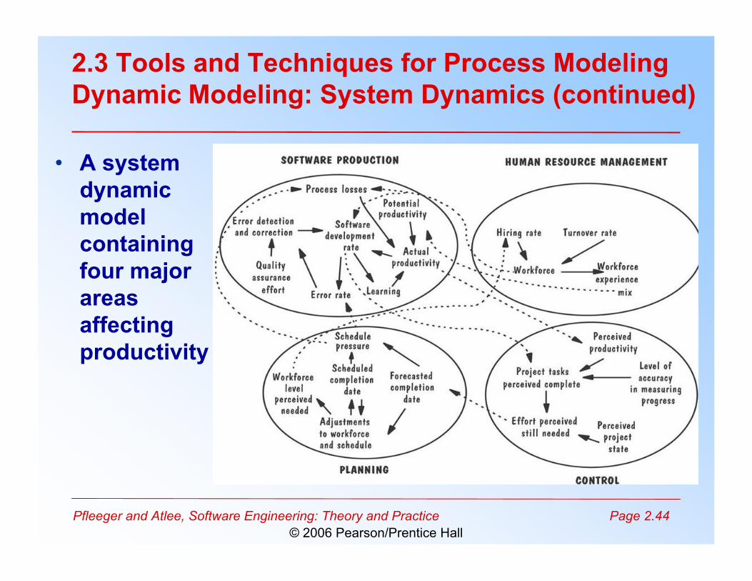
2.3 Tools and Techniques for Process ModelingDynamic Modeling: System Dynamics (continued)
• A systemdynamicmodelcontainingfour majorareasaffectingproductivity
Pfleeger and Atlee, Software Engineering: Theory and Practice Page 2.45© 2006 Pearson/Prentice Hall
2.3 Tools and Techniques for Process ModelingSidebar 2.4 Process Programming
• A program to describe and enact the process– Eliminate uncertainty– Basis of an automated environment to produce software
• Does not capture inherent variability of underlyingdevelopment process– Implementation environment, skill, experience,
understanding the customer needs• Provides only sequence of tasks• Gives no warning of impending problems
Pfleeger and Atlee, Software Engineering: Theory and Practice Page 2.46© 2006 Pearson/Prentice Hall
2.4 Practical Process ModelingMarvel Case Studies
• Uses Marvel process language (MPL)• Three constructs: classes, rules, tool envelopes• Three-part process description
– rule-based specification of process behavior– object-oriented definition of model’s information
process– set of envelopes to interface between Marvel and
external software tools
Pfleeger and Atlee, Software Engineering: Theory and Practice Page 2.47© 2006 Pearson/Prentice Hall
2.4 Practical Process ModelingMarvel Case Studies (continued)
• Involved two AT&T networks– network carried phone calls– signaling network responsible for routing calls and
balancing the network load• Marvel was used to describe the signaling fault
resolution
Pfleeger and Atlee, Software Engineering: Theory and Practice Page 2.48© 2006 Pearson/Prentice Hall
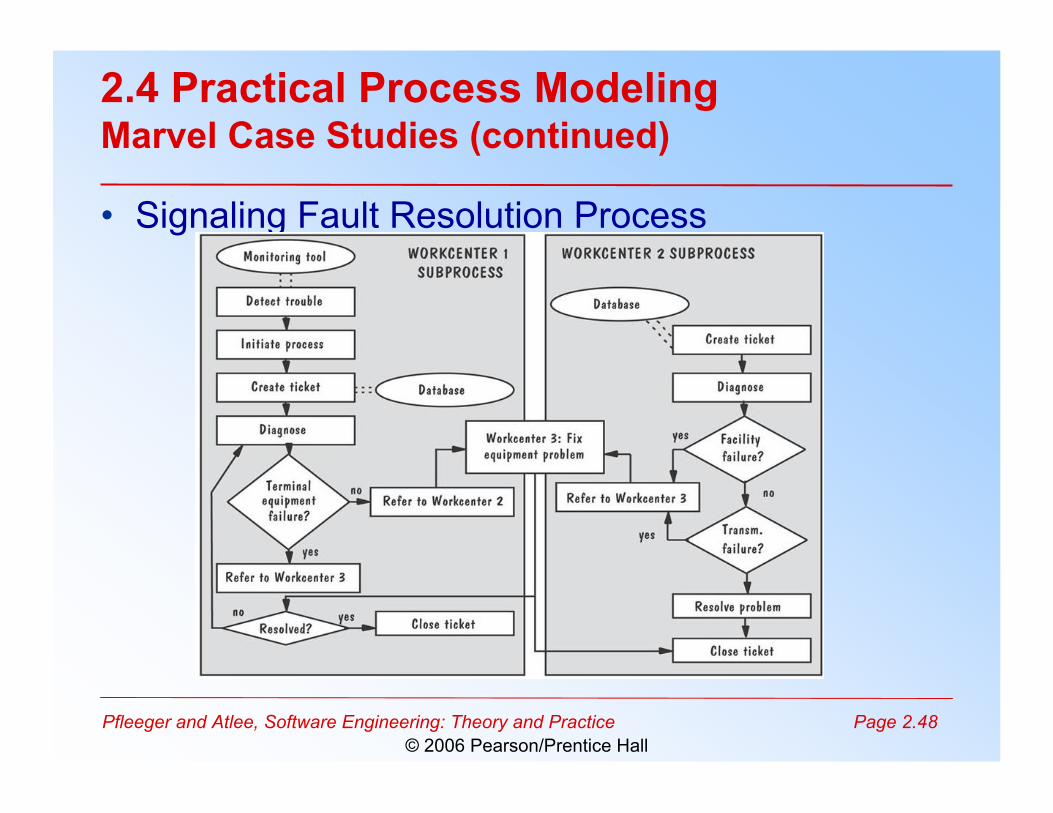
2.4 Practical Process ModelingMarvel Case Studies (continued)
• Signaling Fault Resolution Process
Pfleeger and Atlee, Software Engineering: Theory and Practice Page 2.49© 2006 Pearson/Prentice Hall
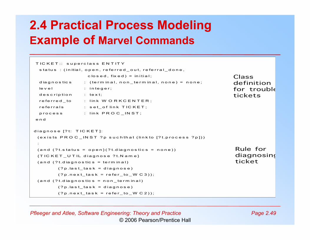
2.4 Practical Process ModelingExample of Marvel Commands
T IC K E T :: s u p e r c l a s s E N T IT Y
s ta tu s : ( i n it ia l , o p e n , r e fe r r e d _ o u t, r e fe r r a l _ d o n e ,
c lo s e d , f ix e d ) = in i t i a l ;
d ia g n o s t ic s : ( te r m in a l , n o n _ te r m in a l , n o n e ) = n o n e ;
le v e l : i n te g e r ;
d e s c r i p t i o n : te x t;
r e fe r r e d _ to : l in k W O R K C E N T E R ;
r e fe r r a l s : s e t_ o f li n k T IC K E T ;
p r o c e s s : l in k P R O C _ IN S T ;
e n d
d i a g n o s e [? t : T IC K E T ]:
( e x i s ts P R O C _ IN S T ? p s u c h th a t ( li n k to [? t .p r o c e s s ? p ]) )
:
( a n d ( ? t.s ta tu s = o p e n } ( ? t.d ia g n o s t i c s = n o n e ) )
{ T IC K E T _ U T IL d i a g n o s e ? t.N a m e }
( a n d ( ? t.d ia g n o s t ic s = te r m in a l )
( ? p . la s t_ ta s k = d i a g n o s e )
( ? p .n e x t_ ta s k = r e fe r _ to _ W C 3 ) ) ;
( a n d ( ? t.d ia g n o s t ic s = n o n _ te r m in a l )
( ? p . la s t_ ta s k = d i a g n o s e )
( ? p .n e x t_ ta s k = r e fe r _ to _ W C 2 ) ) ;
Classdefinitionfor troubletickets
Rule fordiagnosingticket
Pfleeger and Atlee, Software Engineering: Theory and Practice Page 2.50© 2006 Pearson/Prentice Hall
2.4 Practical Process ModelingDesirable Properties of Process Modeling Tools andTechniques
• Facilitates human understanding andcommunication
• Supports process improvement• Supports process management• Provides automated guidance in performing the
process• Supports automated process execution
Pfleeger and Atlee, Software Engineering: Theory and Practice Page 2.51© 2006 Pearson/Prentice Hall
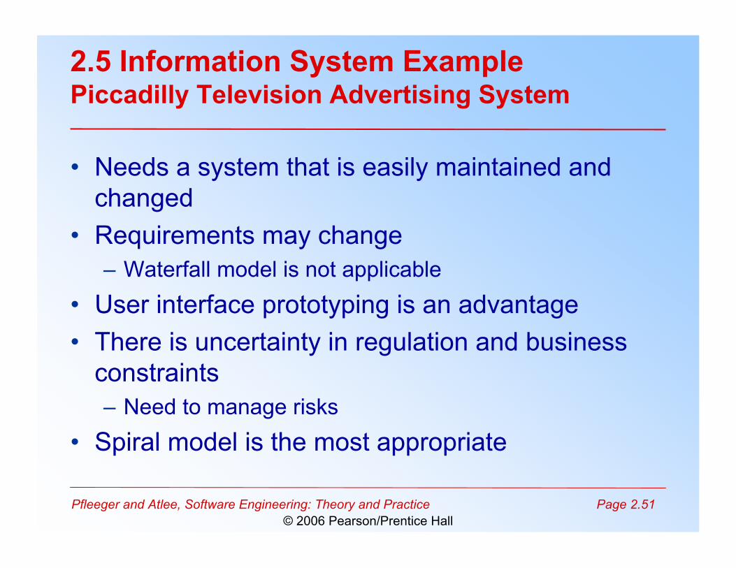
2.5 Information System ExamplePiccadilly Television Advertising System
• Needs a system that is easily maintained andchanged
• Requirements may change– Waterfall model is not applicable
• User interface prototyping is an advantage• There is uncertainty in regulation and business
constraints– Need to manage risks
• Spiral model is the most appropriate
Pfleeger and Atlee, Software Engineering: Theory and Practice Page 2.52© 2006 Pearson/Prentice Hall
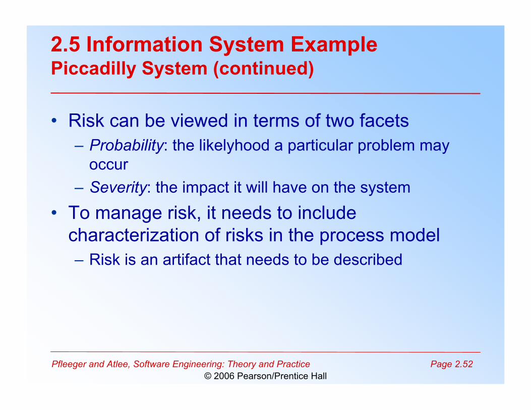
2.5 Information System ExamplePiccadilly System (continued)
• Risk can be viewed in terms of two facets– Probability: the likelyhood a particular problem may
occur– Severity: the impact it will have on the system
• To manage risk, it needs to includecharacterization of risks in the process model– Risk is an artifact that needs to be described
Pfleeger and Atlee, Software Engineering: Theory and Practice Page 2.53© 2006 Pearson/Prentice Hall
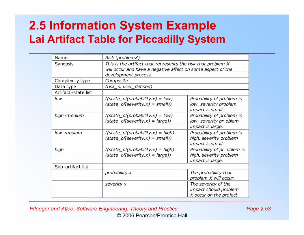
2.5 Information System ExampleLai Artifact Table for Piccadilly System
Name Risk (problemX)
Synopsis This is the artifact that represents the risk that problem X
will occur and have a negative affect on some aspect of the
development process.
Complexity type Composite
Data type (risk_s, user_defined)
Artifact -state list
low ((state_of(probability.x) = low)
(state_of(severity.x) = small))
Probability of problem is
low, severity problem
impact is small.
high -medium ((state_of(probability.x) = low)
(state_of(severity.x) = large))
Probability of problem is
low, severity pr oblem
impact is large.
low-medium ((state_of(probability.x) = high)
(state_of(severity.x) = small))
Probability of problem is
high, severity problem
impact is small.
high ((state_of(probability.x) = high)
(state_of(severity.x) = large))
Probability of pr oblem is
high, severity problem
impact is large.
Sub-artifact list
probability.x The probability that
problem X will occur.
severity.x The severity of the
impact should problem
X occur on the project.
Pfleeger and Atlee, Software Engineering: Theory and Practice Page 2.54© 2006 Pearson/Prentice Hall
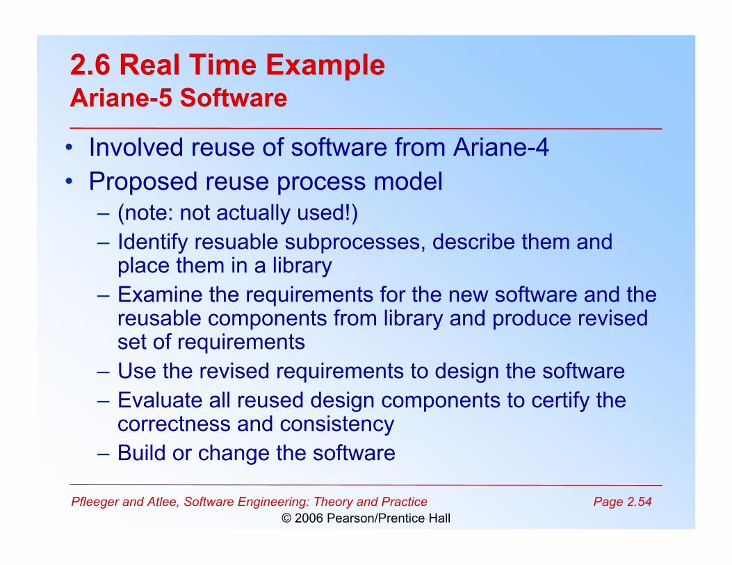
2.6 Real Time ExampleAriane-5 Software
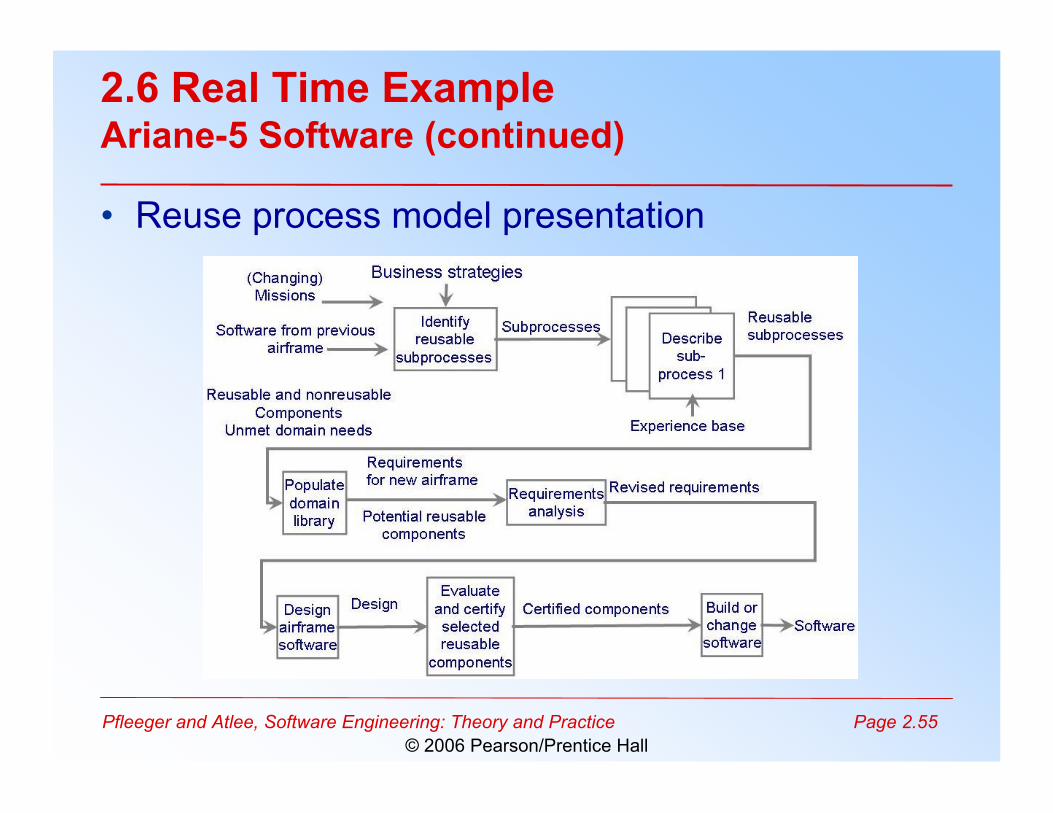
• Involved reuse of software from Ariane-4• Proposed reuse process model
– (note: not actually used!)– Identify resuable subprocesses, describe them and
place them in a library– Examine the requirements for the new software and the
reusable components from library and produce revisedset of requirements
– Use the revised requirements to design the software– Evaluate all reused design components to certify the
correctness and consistency– Build or change the software
Pfleeger and Atlee, Software Engineering: Theory and Practice Page 2.55© 2006 Pearson/Prentice Hall
2.6 Real Time ExampleAriane-5 Software (continued)
• Reuse process model presentation
Pfleeger and Atlee, Software Engineering: Theory and Practice Page 2.56© 2006 Pearson/Prentice Hall
2.7 What this Chapter Means for You
• Process development involves activities,resources, and product
• Process model includes organizational, functional,behavioral, and other perspectives
• A process model is useful for guiding teambehavior, coordination, and collaboration
Pfleeger and Atlee, Software Engineering: Theory and Practice Page 2.57© 2006 Pearson/Prentice Hall
Coming Up Next…
• Week 4– Lecture 7
• Chapter 3 of Concurrency Textbook– Lecture 8
• Chapter 4 of Concurrency Textbook