Embed Size (px)
Citation preview

CS162Operating Systems andSystems Programming
Lecture 17
Disk Management andFile Systems
October 29, 2008
Prof. John Kubiatowicz
http://inst.eecs.berkeley.edu/~cs162

Lec 17.210/29/08 Kubiatowicz CS162 ©UCB Fall 2008
Review: Want Standard Interfaces to Devices
• Block Devices: e.g. disk drives, tape drives, Cdrom– Access blocks of data– Commands include open(), read(), write(), seek()– Raw I/O or file-system access– Memory-mapped file access possible
• Character Devices: e.g. keyboards, mice, serial ports, some USB devices– Single characters at a time– Commands include get(), put()– Libraries layered on top allow line editing
• Network Devices: e.g. Ethernet, Wireless, Bluetooth– Different enough from block/character to have own
interface– Unix and Windows include socket interface
» Separates network protocol from network operation» Includes select() functionality
– Usage: pipes, FIFOs, streams, queues, mailboxes

Lec 17.310/29/08 Kubiatowicz CS162 ©UCB Fall 2008
Review: How Does User Deal with Timing?
• Blocking Interface: “Wait”– When request data (e.g. read() system call), put
process to sleep until data is ready– When write data (e.g. write() system call), put
process to sleep until device is ready for data
• Non-blocking Interface: “Don’t Wait”– Returns quickly from read or write request with
count of bytes successfully transferred– Read may return nothing, write may write nothing
• Asynchronous Interface: “Tell Me Later”– When request data, take pointer to user’s buffer,
return immediately; later kernel fills buffer and notifies user
– When send data, take pointer to user’s buffer, return immediately; later kernel takes data and notifies user

Lec 17.410/29/08 Kubiatowicz CS162 ©UCB Fall 2008
Goals for Today
• Finish Discussing I/O Systems– Hardware Access– Device Drivers
• Disk Performance– Hardware performance parameters– Queuing Theory
• File Systems– Structure, Naming, Directories, and Caching
Note: Some slides and/or pictures in the following areadapted from slides ©2005 Silberschatz, Galvin, and Gagne
Note: Some slides and/or pictures in the following areadapted from slides ©2005 Silberschatz, Galvin, and Gagne. Many slides generated from my lecture notes by Kubiatowicz.

Lec 17.510/29/08 Kubiatowicz CS162 ©UCB Fall 2008
Main components of Intel Chipset: Pentium 4
• Northbridge:– Handles memory– Graphics
• Southbridge: I/O– PCI bus– Disk controllers– USB controllers– Audio– Serial I/O– Interrupt
controller– Timers

Lec 17.610/29/08 Kubiatowicz CS162 ©UCB Fall 2008
DeviceController
readwrite
controlstatus
AddressableMemoryand/orQueuesRegisters
(port 0x20)
HardwareController
Memory MappedRegion: 0x8f008020
BusInterface
How does the processor talk to the device?
• CPU interacts with a Controller– Contains a set of registers that
can be read and written– May contain memory for request
queues or bit-mapped images • Regardless of the complexity of the connections
and buses, processor accesses registers in two ways: – I/O instructions: in/out instructions
» Example from the Intel architecture: out 0x21,AL– Memory mapped I/O: load/store instructions
» Registers/memory appear in physical address space» I/O accomplished with load and store instructions
Address+Data
Interrupt Request
Processor Memory Bus
CPU
RegularMemory
InterruptController
BusAdaptor
BusAdaptor
Other Devicesor Buses

Lec 17.710/29/08 Kubiatowicz CS162 ©UCB Fall 2008
Memory-Mapped Display Controller Example• Memory-Mapped:
– Hardware maps control registers and display memory to physical address space» Addresses set by hardware
jumpers or programming at boot time
– Simply writing to display memory (also called the “frame buffer”) changes image on screen» Addr: 0x8000F000—0x8000FFFF
– Writing graphics description to command-queue area » Say enter a set of triangles that
describe some scene» Addr: 0x80010000—0x8001FFFF
– Writing to the command register may cause on-board graphics hardware to do something» Say render the above scene» Addr: 0x0007F004
• Can protect with page tables
DisplayMemory
0x8000F000
0x80010000
Physical AddressSpace
Status0x0007F000Command0x0007F004
GraphicsCommand
Queue
0x80020000

Lec 17.810/29/08 Kubiatowicz CS162 ©UCB Fall 2008
Transferring Data To/From Controller• Programmed I/O:
– Each byte transferred via processor in/out or load/store
– Pro: Simple hardware, easy to program– Con: Consumes processor cycles proportional to
data size• Direct Memory Access:
– Give controller access to memory bus– Ask it to transfer data to/from memory directly
• Sample interaction with DMA controller (from book):

Lec 17.910/29/08 Kubiatowicz CS162 ©UCB Fall 2008
A Kernel I/O Structure

Lec 17.1010/29/08 Kubiatowicz CS162 ©UCB Fall 2008
Administrivia
• Group Evaluations (Both Projects 1 and 2)– These MUST be done: you will get a ZERO on
your project score if you don’t fill them out– We will be asking you about them, so make
sure you are careful to fill them out honestly
• Next Week’s Sections– Fill out a survey form to see how class is
going– Give you an opportunity to give feedback
• Other things– Group problems? Don’t wait.– Talk to TA/talk to me
» Let’s get things fixed!

Lec 17.1110/29/08 Kubiatowicz CS162 ©UCB Fall 2008
Device Drivers• Device Driver: Device-specific code in the
kernel that interacts directly with the device hardware– Supports a standard, internal interface– Same kernel I/O system can interact easily with
different device drivers– Special device-specific configuration supported
with the ioctl() system call• Device Drivers typically divided into two
pieces:– Top half: accessed in call path from system calls
» implements a set of standard, cross-device calls like open(), close(), read(), write(), ioctl(), strategy()
» This is the kernel’s interface to the device driver» Top half will start I/O to device, may put thread to
sleep until finished– Bottom half: run as interrupt routine
» Gets input or transfers next block of output» May wake sleeping threads if I/O now complete

Lec 17.1210/29/08 Kubiatowicz CS162 ©UCB Fall 2008
Life Cycle of An I/O Request
Device DriverTop Half
Device DriverBottom Half
DeviceHardware
Kernel I/OSubsystem
UserProgram

Lec 17.1310/29/08 Kubiatowicz CS162 ©UCB Fall 2008
I/O Device Notifying the OS•The OS needs to know when:
–The I/O device has completed an operation–The I/O operation has encountered an error
•I/O Interrupt:–Device generates an interrupt whenever it needs service
–Handled in bottom half of device driver» Often run on special kernel-level stack
–Pro: handles unpredictable events well–Con: interrupts relatively high overhead
•Polling:–OS periodically checks a device-specific status register» I/O device puts completion information in status
register» Could use timer to invoke lower half of drivers
occasionally–Pro: low overhead–Con: may waste many cycles on polling if infrequent or unpredictable I/O operations
•Actual devices combine both polling and interrupts–For instance: High-bandwidth network device: » Interrupt for first incoming packet» Poll for following packets until hardware empty

Lec 17.1410/29/08 Kubiatowicz CS162 ©UCB Fall 2008
Hard Disk Drives
IBM/Hitachi Microdrive
Western Digital Drivehttp://www.storagereview.com/guide/
Read/Write HeadSide View

Lec 17.1510/29/08 Kubiatowicz CS162 ©UCB Fall 2008
Properties of a Hard Magnetic Disk
• Properties– Independently addressable element: sector
» OS always transfers groups of sectors together—”blocks”
– A disk can access directly any given block of information it contains (random access). Can access any file either sequentially or randomly.
– A disk can be rewritten in place: it is possible to read/modify/write a block from the disk
• Typical numbers (depending on the disk size):– 500 to more than 20,000 tracks per surface– 32 to 800 sectors per track
» A sector is the smallest unit that can be read or written
• Zoned bit recording– Constant bit density: more sectors on outer tracks– Speed varies with track location
Track
Sector
Platters

Lec 17.1610/29/08 Kubiatowicz CS162 ©UCB Fall 2008
Disk I/O Performance
Response Time = Queue+Disk Service Time
UserThread
Queue[OS Paths]
Con
trolle
r
Disk
• Performance of disk drive/file system– Metrics: Response Time, Throughput– Contributing factors to latency:
» Software paths (can be loosely modeled by a queue)» Hardware controller» Physical disk media
• Queuing behavior:– Can lead to big increases of latency as utilization
approaches 100%
100%
ResponseTime (ms)
Throughput (Utilization)(% total BW)
0
100
200
300
0%

Lec 17.1710/29/08 Kubiatowicz CS162 ©UCB Fall 2008
Magnetic Disk Characteristic• Cylinder: all the tracks under the
head at a given point on all surface• Read/write data is a three-stage
process:– Seek time: position the head/arm over the proper
track (into proper cylinder)– Rotational latency: wait for the desired sector
to rotate under the read/write head– Transfer time: transfer a block of bits (sector)
under the read-write head• Disk Latency = Queueing Time + Controller time
+Seek Time + Rotation Time + Xfer
Time
• Highest Bandwidth: – Transfer large group of blocks sequentially from
one track
SectorTrack
CylinderHead
Platter
SoftwareQueue
(Device Driver)
Hard
ware
Con
trolle
r Media Time
(Seek+Rot+Xfer)
Req
uest
Resu
lt

Lec 17.1810/29/08 Kubiatowicz CS162 ©UCB Fall 2008
Typical Numbers of a Magnetic Disk• Average seek time as reported by the industry:
– Typically in the range of 8 ms to 12 ms– Due to locality of disk reference may only be 25%
to 33% of the advertised number• Rotational Latency:
– Most disks rotate at 3,600 to 7200 RPM (Up to 15,000RPM or more)
– Approximately 16 ms to 8 ms per revolution, respectively
– An average latency to the desired information is halfway around the disk: 8 ms at 3600 RPM, 4 ms at 7200 RPM
• Transfer Time is a function of:– Transfer size (usually a sector): 512B – 1KB per
sector– Rotation speed: 3600 RPM to 15000 RPM– Recording density: bits per inch on a track– Diameter: ranges from 1 in to 5.25 in– Typical values: 2 to 50 MB per second
• Controller time depends on controller hardware• Cost drops by factor of two per year (since 1991)
Lec 17.1910/29/08 Kubiatowicz CS162 ©UCB Fall 2008
Disk Performance
• Assumptions:– Ignoring queuing and controller times for now– Avg seek time of 5ms, avg rotational delay of 4ms– Transfer rate of 4MByte/s, sector size of 1 KByte
• Random place on disk:– Seek (5ms) + Rot. Delay (4ms) + Transfer (0.25ms)– Roughly 10ms to fetch/put data: 100 KByte/sec
• Random place in same cylinder:– Rot. Delay (4ms) + Transfer (0.25ms)– Roughly 5ms to fetch/put data: 200 KByte/sec
• Next sector on same track:– Transfer (0.25ms): 4 MByte/sec
• Key to using disk effectively (esp. for filesystems) is to minimize seek and rotational delays

Lec 17.2010/29/08 Kubiatowicz CS162 ©UCB Fall 2008
Disk Tradeoffs
• How do manufacturers choose disk sector sizes?– Need 100-1000 bits between each sector to allow
system to measure how fast disk is spinning and to tolerate small (thermal) changes in track length
• What if sector was 1 byte?– Space efficiency – only 1% of disk has useful space– Time efficiency – each seek takes 10 ms, transfer
rate of 50 – 100 Bytes/sec
• What if sector was 1 KByte?– Space efficiency – only 90% of disk has useful space– Time efficiency – transfer rate of 100 KByte/sec
• What if sector was 1 MByte?– Space efficiency – almost all of disk has useful
space– Time efficiency – transfer rate of 4 MByte/sec
Lec 17.2110/29/08 Kubiatowicz CS162 ©UCB Fall 2008
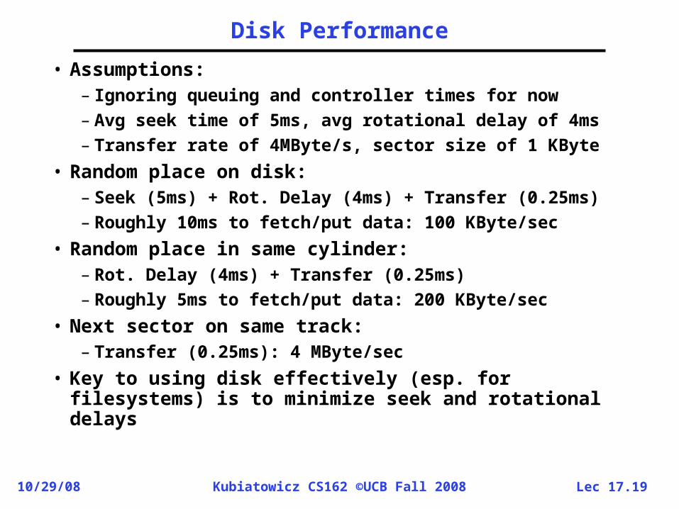
DeparturesArrivals
Queuing System
Introduction to Queuing Theory
• What about queuing time??– Let’s apply some queuing theory– Queuing Theory applies to long term, steady state
behavior Arrival rate = Departure rate• Little’s Law:
Mean # tasks in system = arrival rate x mean response time– Observed by many, Little was first to prove– Simple interpretation: you should see the same
number of tasks in queue when entering as when leaving.
• Applies to any system in equilibrium, as long as nothing in black box is creating or destroying tasks– Typical queuing theory doesn’t deal with transient
behavior, only steady-state behavior
Queue
Con
trolle
r
Disk

Lec 17.2210/29/08 Kubiatowicz CS162 ©UCB Fall 2008
Background: Use of random distributions
• Server spends variable time with customers– Mean (Average) m1 = p(T)T– Variance 2 = p(T)(T-m1)2 = p(T)T2-m12
– Squared coefficient of variance: C = 2/m12
Aggregate description of the distribution.
• Important values of C:– No variance or deterministic C=0 – “memoryless” or exponential C=1
» Past tells nothing about future» Many complex systems (or aggregates)
well described as memoryless – Disk response times C 1.5 (majority seeks <
avg)
Mean (m1)
mean
Memoryless
Distributionof service times

Lec 17.2310/29/08 Kubiatowicz CS162 ©UCB Fall 2008
A Little Queuing Theory: Some Results• Assumptions:
– System in equilibrium; No limit to the queue– Time between successive arrivals is random and
memoryless
• Parameters that describe our system: : mean number of arriving customers/second– Tser: mean time to service a customer (“m1”)– C: squared coefficient of variance = 2/m12
– μ: service rate = 1/Tser– u: server utilization (0u1): u = /μ = Tser
• Parameters we wish to compute:– Tq: Time spent in queue– Lq: Length of queue = Tq (by Little’s law)
• Results:– Memoryless service distribution (C = 1):
» Called M/M/1 queue: Tq = Tser x u/(1 – u)– General service distribution (no restrictions), 1 server:
» Called M/G/1 queue: Tq = Tser x ½(1+C) x u/(1 – u))
Arrival Rate
Queue ServerService Rate
μ=1/Tser

Lec 17.2410/29/08 Kubiatowicz CS162 ©UCB Fall 2008
A Little Queuing Theory: An Example• Example Usage Statistics:
– User requests 10 x 8KB disk I/Os per second– Requests & service exponentially distributed (C=1.0)– Avg. service = 20 ms (From controller+seek+rot+trans)
• Questions: – How utilized is the disk?
» Ans: server utilization, u = Tser– What is the average time spent in the queue?
» Ans: Tq– What is the number of requests in the queue?
» Ans: Lq– What is the avg response time for disk request?
» Ans: Tsys = Tq + Tser• Computation:
(avg # arriving customers/s) = 10/sTser (avg time to service customer) = 20 ms (0.02s)u (server utilization) = x Tser= 10/s x .02s = 0.2Tq (avg time/customer in queue) = Tser x u/(1 – u)
= 20 x 0.2/(1-0.2) = 20 x 0.25 = 5 ms (0 .005s)Lq (avg length of queue) = x Tq=10/s x .005s = 0.05Tsys (avg time/customer in system) =Tq + Tser= 25 ms

Lec 17.2510/29/08 Kubiatowicz CS162 ©UCB Fall 2008
Summary
• I/O Controllers: Hardware that controls actual device– Processor Accesses through I/O instructions or
load/store to special physical memory• Notification mechanisms
– Interrupts– Polling: Report results through status register
that processor looks at periodically • Disk Performance:
– Queuing time + Controller + Seek + Rotational + Transfer
– Rotational latency: on average ½ rotation– Transfer time: spec of disk depends on rotation
speed and bit storage density• Queuing Latency:
– M/M/1 and M/G/1 queues: simplest to analyze– As utilization approaches 100%, latency
Tq = Tser x ½(1+C) x u/(1 – u))