Embed Size (px)
Citation preview
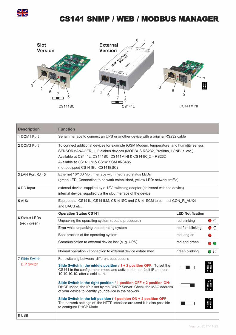
Description Function
1 COM1 Port Serial Interface to connect an UPS or another device with a original RS232 cable
2 COM2 Port
To connect additional devices for example (GSM Modem, temperature and humidity sensor,
SENSORMANAGER_II, Fieldbus devices (MODBUS RS232, Profibus, LONBus, etc.).
Available at CS141L, CS141SC, CS141MINI & CS141R_2 = RS232
Available at CS141LM & CS141SCM =RS485
(not equipped CS141BL, CS141BSC)
3 LAN Port RJ 45 Ethernet 10/100 Mbit Interface with integrated status LEDs
(green LED: Connection to network established, yellow LED: network traffic)
4 DC Input external device: supplied by a 12V switching adapter (delivered with the device)
internal device: supplied via the slot interface of the device
5 AUX Equipped at CS141L, CS141LM, CS141SC and CS141SCM to connect CON_R_AUX4
and BACS etc.
6 Status LEDs
(red / green)
Operation Status CS141 LED Notification
Unpacking the operating system (update procedure) red blinking
Error while unpacking the operating system red fast blinking
Boot process of the operating system red long on
Communication to external device lost (e. g. UPS) red and green
Normal operation - connection to external device established green blinking
7 Slide Switch
DIP Switch
For switching between different boot options . Slide Switch in the middle position / 1 + 2 position OFF: To set the CS141 in the configuration mode and activated the default IP address 10.10.10.10. after a cold start.
Slide Switch in the right position / 1 position OFF + 2 position ON: DHCP Mode, the IP is set by the DHCP Server. Check the MAC address of your device to identify your device in the network.
Slide Switch in the left position / 1 position ON + 2 position OFF: The network settings of the HTTP interface are used it is also possible to configure DHCP Mode.
8 USB
5
3 2
6 7
1 8 4
CS141SC CS141L CS141MINI
5
3 2
6 7
2
3 6
7
Slot Version
External Version
CS141 SNMP / WEB / MODBUS MANAGER
Version: 2017-11-23
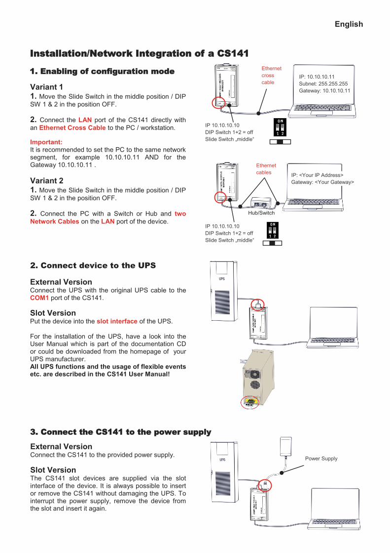
Variant 1 1. Move the Slide Switch in the middle position / DIP
SW 1 & 2 in the position OFF.
2. Connect the LAN port of the CS141 directly with
an Ethernet Cross Cable to the PC / workstation.
Important: It is recommended to set the PC to the same network segment, for example 10.10.10.11 AND for the Gateway 10.10.10.11 .
Variant 2 1. Move the Slide Switch in the middle position / DIP
SW 1 & 2 in the position OFF.
2. Connect the PC with a Switch or Hub and two
Network Cables on the LAN port of the device.
External Version Connect the UPS with the original UPS cable to the COM1 port of the CS141.
Slot Version Put the device into the slot interface of the UPS. For the installation of the UPS, have a look into the User Manual which is part of the documentation CD or could be downloaded from the homepage of your UPS manufacturer. All UPS functions and the usage of flexible events etc. are described in the CS141 User Manual!
2. Connect device to the UPS
IP 10.10.10.10
DIP Switch 1+2 = off
Slide Switch „middle“
IP: 10.10.10.11
Subnet: 255.255.255
Gateway: 10.10.10.11
Ethernet
cross
cable
Ethernet
cables IP: <Your IP Address>
Gateway: <Your Gateway>
IP 10.10.10.10
DIP Switch 1+2 = off
Slide Switch „middle“
Hub/Switch
Power Supply
3. Connect the CS141 to the power supply
External Version Connect the CS141 to the provided power supply.
Slot Version The CS141 slot devices are supplied via the slot interface of the device. It is always possible to insert or remove the CS141 without damaging the UPS. To interrupt the power supply, remove the device from the slot and insert it again.
English
Installation/Network Integration of a CS141
1. Enabling of configuration mode
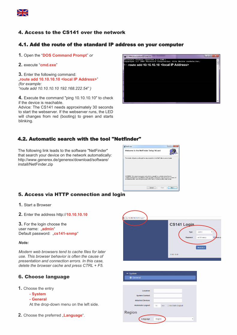
4.1. Add the route of the standard IP address on your computer
1. Open the “DOS Command Prompt” or
2. execute “cmd.exe”
3. Enter the following command:
„route add 10.10.10.10 <local IP Address>” (for example: “route add 10.10.10.10 192.168.222.54” )
4. Execute the command "ping 10.10.10.10" to check
if the device is reachable. Advice: The CS141 needs approximately 30 seconds to start the webserver. If the webserver runs, the LED will changes from red (booting) to green and starts blinking.
4.2. Automatic search with the tool "Netfinder"
The following link leads to the software "NetFinder" that search your device on the network automatically: http://www.generex.de/generex/download/software/install/NetFinder.zip
1. Start a Browser
2. Enter the address http://10.10.10.10
3. For the login choose the
user name: „admin“ Default password: „cs141-snmp“ Note: Modern web browsers tend to cache files for later use. This browser behavior is often the cause of presentation and connection errors. In this case, delete the browser cache and press CTRL + F5.
5. Access via HTTP connection and login
4. Access to the CS141 over the network
6. Choose language
1. Choose the entry
- System
- General
At the drop-down menu on the left side.
2. Choose the preferred „Language“.
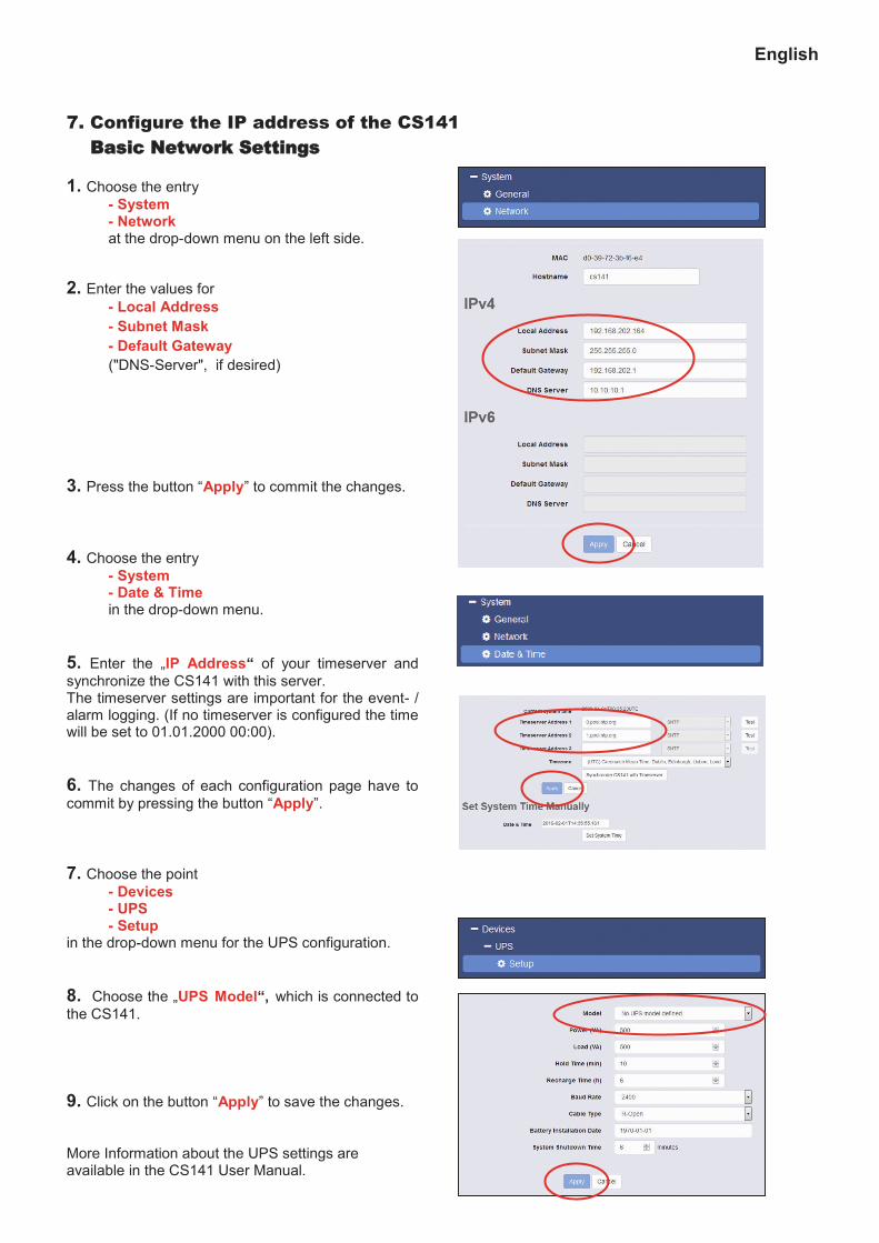
1. Choose the entry
- System - Network at the drop-down menu on the left side.
2. Enter the values for
- Local Address
- Subnet Mask
- Default Gateway
("DNS-Server", if desired)
3. Press the button “Apply” to commit the changes.
4. Choose the entry
- System - Date & Time in the drop-down menu.
5. Enter the „IP Address“ of your timeserver and
synchronize the CS141 with this server. The timeserver settings are important for the event- / alarm logging. (If no timeserver is configured the time will be set to 01.01.2000 00:00).
6. The changes of each configuration page have to
commit by pressing the button “Apply”.
7. Choose the point
- Devices - UPS - Setup in the drop-down menu for the UPS configuration.
8. Choose the „UPS Model“, which is connected to
the CS141.
9. Click on the button “Apply” to save the changes.
More Information about the UPS settings are available in the CS141 User Manual.
7. Configure the IP address of the CS141
Basic Network Settings
English
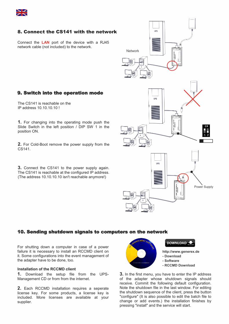
Connect the LAN port of the device with a RJ45 network cable (not included) to the network.
The CS141 is reachable on the IP address 10.10.10.10 !
1. For changing into the operating mode push the
Slide Switch in the left position / DIP SW 1 in the position ON.
2. For Cold-Boot remove the power supply from the
CS141.
3. Connect the CS141 to the power supply again.
The CS141 is reachable at the configured IP address. (The address 10.10.10.10 isn't reachable anymore!)
10. Sending shutdown signals to computers on the network
For shutting down a computer in case of a power failure it is necessary to install an RCCMD client on it. Some configurations into the event management of the adapter have to be done, too. Installation of the RCCMD client
1. Download the setup file from the UPS-
Management CD or from from the internet.
2. Each RCCMD installation requires a seperate
license key. For some products, a license key is included. More licenses are available at your supplier.
http://www.generex.de
- Download
- Software
- RCCMD Download
Network
8. Connect the CS141 with the network
9. Switch into the operation mode
Power Supply
3. In the first menu, you have to enter the IP address
of the adapter whose shutdown signals should receive. Commit the following default configuration. Note the shutdown file in the last window. For editing the shutdown sequence of the client, press the button "configure" (It is also possible to edit the batch file to change or add events.) the installation finishes by pressing "install" and the service will start.

1. Choose the entry
- Devices - UPS - Events from the drop-down menu.
2. Click the Button “+” next to the event “Powerfail”.
3. The Job-Editor starts. Choose the option
“RCCMD Shutdown” from the menu.
4. Enter the „IP Address“ of your client (The
Listener Port is usually 6003). At the right side you can specify when the shutdown signal is going to be released, for example „At 300 seconds remaining time“.
5. Click the button „Save Configuration“.
6. For security reasons it is recommended to make
the same RCCMD shutdown entries at „Powerfail“ for
the Event “Battery low” - but here without any delays
to avoid that the server crashes because of low
battery alarm!
The CS141 can be a variety of environmental
sensors and other measuring devices are combined,
to temperature, humidity, fire and smoke, motion and
intrusion, pressure, levels etc. to be monitored.
In addition, other components such as various
mounting brackets, BACnet Converter, PROFIBUS
Converter etc. available. Please ask your UPS
manufacturers / suppliers for more detailed
information about the options available.
11. Event configuration for the CS141
12. Options for the CS141
English