Embed Size (px)
Citation preview
BULLETIN P-119
INDUSTRIAL VALVES LTD.
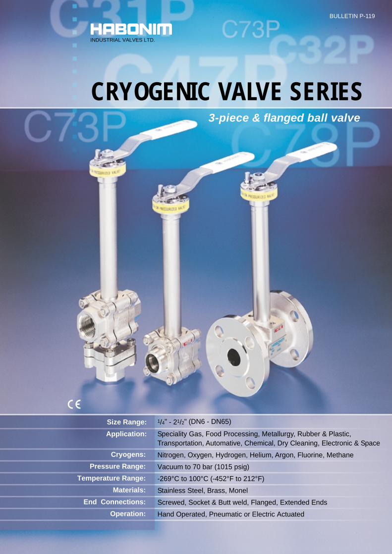
3-piece & flanged ball valve
CRYOGENIC VALVE SERIES
1/4" - 21/2" (DN6 - DN65)
Speciality Gas, Food Processing, Metallurgy, Rubber & Plastic,Transportation, Automative, Chemical, Dry Cleaning, Electronic & Space
Nitrogen, Oxygen, Hydrogen, Helium, Argon, Fluorine, Methane
Vacuum to 70 bar (1015 psig)
-269°C to 100°C (-452°F to 212°F)
Stainless Steel, Brass, Monel
Screwed, Socket & Butt weld, Flanged, Extended Ends
Hand Operated, Pneumatic or Electric Actuated
Size Range:
Application:
Cryogens:
Pressure Range:
Temperature Range:
Materials:
End Connections:
Operation:
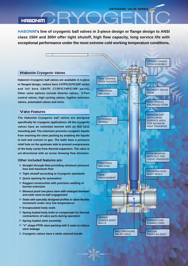
HABONIM's line of cryogenic ball valves in 3-piece design or flange design to ANSI
class 150# and 300# offer tight shutoff, high flow capacity, long service life with
exceptional performance under the most extreme cold working temperature conditions.
ENCAPSULATEDBODY SEALS
BLOWOUT PROOFSTEM
SPRING LOADEDSTEM ASSEMBLY
NARROW GAPWITH LARGESURFACE AREAFOR MAXIMUMHEAT TRANSFER
“VEE” SHAPEDSTEM PACKING
PRECISIONWELDING
HIGH TENSILEENLARGED STEM
EXTENDEDBONNET
WIDEENGAGEMENT
PRECISIONWELDING
SPECIALPROFILED SEAT
STEM BEARINGWITH SLIT FORLIQUID TRANSFER
SPRINGLOADED BODYBOLTS
BALL PRESSURERELIEF HOLE
CRYOGENIC VALVE SERIES
VARIOUS ENDCONNECTORS
2
Straight through-flow providing minimum pressureloss and maximum flow
Tight shutoff according to Cryogenic standards
Quick opening for automation
Rugged construction with precision welding ofbonnet extension
Blowout proof one-piece stem with enlarged diameterand wide stem-to-ball engagement
Seats with specially designed profiles to allow flexiblemovement under very low temperatures
Encapsulated body seals
Spring loaded body bolts to compensate for thermalcontractions of valve parts during operation
Spring loaded stem assembly
“V” shape PTFE stem packing with 5 seals to reducestem leakage
Cryogenic valves have a white sleeved handle
Other included features are:
The Habonim Cryogenic ball valves are designed
specifically for cryogenic applications. All the cryogenic
valves have an extended bonnet with an ISO 5211
mounting pad. The extension prevents cryogenic liquids
from reaching the stem packing by enabling the liquids
to boil and convert to gas. The balls have a pressure
relief hole on the upstream side to prevent overpressure
of the body cavity from thermal expansion. The valve is
uni-directional with an arrow showing flow direction.
Valve Features
Habonim Cryogenic ball valves are available in 3-piece
or flanged design, reduce bore C47P/C31P/C32P series
and full bore CB47P, C73P/C74P/C78P series.
Other valve options include diverter valves, V-Port
control valves, high cycling valves, fugitive emission
valves, automated valves and more.
Habonim Cryogenic Valves
1/2”- 2” C47P Series
Temperature °F
°C
-450 -400 -350 -300 -250 -200 -150 -100 -50 0 50 100 150 200
-250 -225 -200
-196
-150 -125-270 -100 -75 -50 -25 0 25 50 75 100
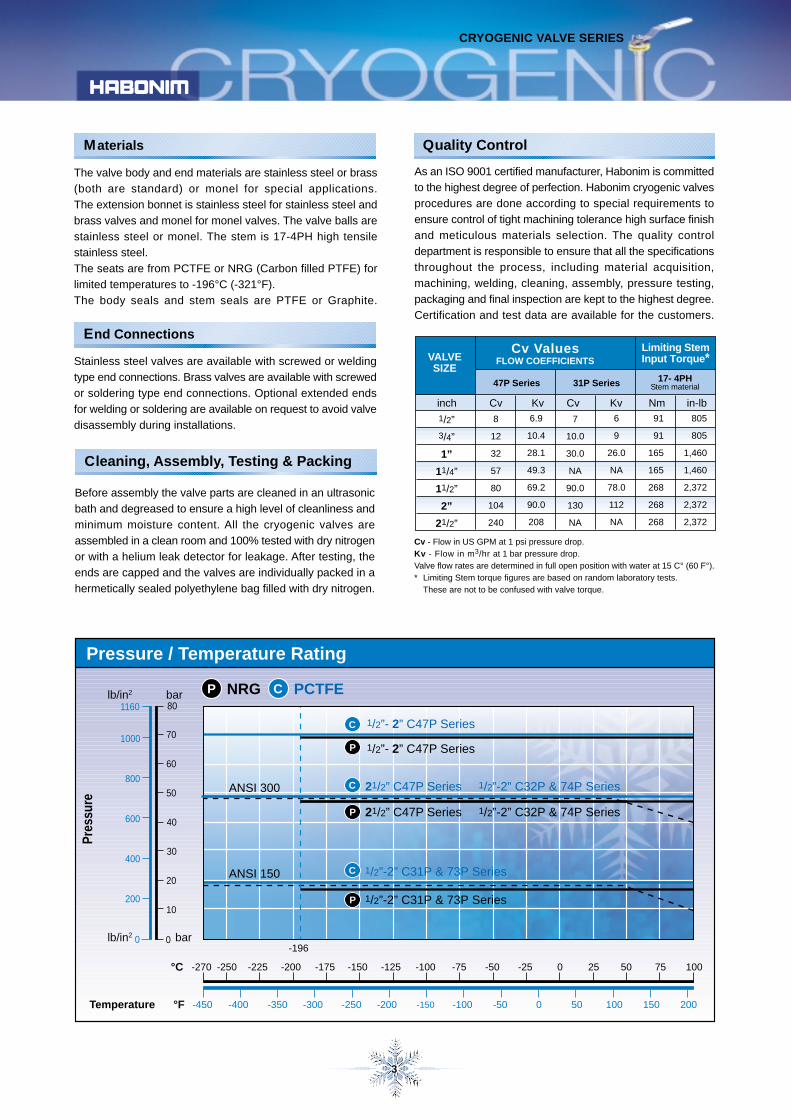
NRGP PCTFEC
Pressure / Temperature Rating
Pre
ssur
e
bar80
0lb/in2 0
1160
bar
lb/in2
70
60
50
40
30
20
10200
400
600
800
1000
Materials
3
Stainless steel valves are available with screwed or welding
type end connections. Brass valves are available with screwed
or soldering type end connections. Optional extended ends
for welding or soldering are available on request to avoid valve
disassembly during installations.
The valve body and end materials are stainless steel or brass
(both are standard) or monel for special applications.
The extension bonnet is stainless steel for stainless steel and
brass valves and monel for monel valves. The valve balls are
stainless steel or monel. The stem is 17-4PH high tensile
stainless steel.
The seats are from PCTFE or NRG (Carbon filled PTFE) for
limited temperatures to -196°C (-321°F).
The body seals and stem seals are PTFE or Graphite.
CRYOGENIC VALVE SERIES
As an ISO 9001 certified manufacturer, Habonim is committed
to the highest degree of perfection. Habonim cryogenic valves
procedures are done according to special requirements to
ensure control of tight machining tolerance high surface finish
and meticulous materials selection. The quality control
department is responsible to ensure that all the specifications
throughout the process, including material acquisition,
machining, welding, cleaning, assembly, pressure testing,
packaging and final inspection are kept to the highest degree.
Certification and test data are available for the customers.
Quality Control
Before assembly the valve parts are cleaned in an ultrasonic
bath and degreased to ensure a high level of cleanliness and
minimum moisture content. All the cryogenic valves are
assembled in a clean room and 100% tested with dry nitrogen
or with a helium leak detector for leakage. After testing, the
ends are capped and the valves are individually packed in a
hermetically sealed polyethylene bag filled with dry nitrogen.
Cleaning, Assembly, Testing & Packing
End Connections
Cv - Flow in US GPM at 1 psi pressure drop.Kv - Flow in m3/hr at 1 bar pressure drop.Valve flow rates are determined in full open position with water at 15 C° (60 F°).* Limiting Stem torque figures are based on random laboratory tests.
These are not to be confused with valve torque.
Cv ValuesFLOW COEFFICIENTS
Limiting StemInput Torque*
47P Series
VALVESIZE
1/2”
3/4”
1”
11/4”
11/2”
2”
21/2”
Cv Kv
8
12
32
57
80
104
240
6.9
10.4
28.1
49.3
69.2
90.0
208
Nm in-lb
17- 4PHStem material
91
91
165
165
268
268
268
805
805
1,460
1,460
2,372
2,372
2,372
inch
31P Series
7
10.0
30.0
NA
90.0
130
NA
6
9
26.0
NA
78.0
112
NA
Cv Kv
1/2”- 2” C47P Series
21/2” C47P Series 1/2”-2” C32P & 74P Series
21/2” C47P Series 1/2”-2” C32P & 74P SeriesP
C
P
C
1/2”-2” C31P & 73P Series
1/2”-2” C31P & 73P SeriesP
CANSI 150
ANSI 300
-175
C47P
22
2
6
9
4
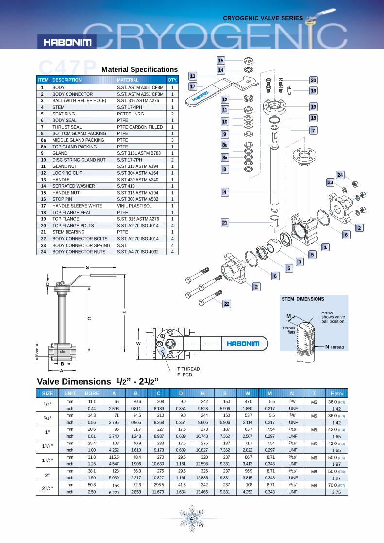
Material Specifications
123456788a8b9101112131415161718192021222324
BODYBODY CONNECTORBALL (WITH RELIEF HOLE)STEMSEAT RINGBODY SEALTHRUST SEALBOTTOM GLAND PACKINGMIDDLE GLAND PACKINGTOP GLAND PACKINGGLANDDISC SPRING GLAND NUTGLAND NUTLOCKING CLIPHANDLESERRATED WASHERHANDLE NUTSTOP PINHANDLE SLEEVE WHITETOP FLANGE SEALTOP FLANGETOP FLANGE BOLTSSTEM BEARINGBODY CONNECTOR BOLTSBODY CONNECTOR SPRINGBODY CONNECTOR NUTS
S.ST. ASTM A351 CF8MS.ST. ASTM A351 CF3MS.ST. 316 ASTM A276S.ST 17-4PHPCTFE, NRGPTFEPTFE CARBON FILLEDPTFEPTFEPTFES.ST 316L ASTM B783S.ST 17-7PHS.ST 316 ASTM A194S.ST 304 ASTM A164S.ST 430 ASTM A240S.ST 410S.ST 316 ASTM A194S.ST 303 ASTM A582VINIL PLASTISOLPTFES.ST. 316 ASTM A276S.ST. A2-70 ISO 4014PTFES.ST. A2-70 ISO 4014S.ST.S.ST. A4-70 ISO 4032
11112111311211111111141444
ITEM DESCRIPTION MATERIAL QTY.
Bor
e
1
15
1413
17
12
11
10
8b
8a
8
20
16
19
18
7
24
23
1
5
35
6
2
4
21
H
S
D
B
A
C
CRYOGENIC VALVE SERIES
W
T THREADF PCD
Arrowshows valveball position
N Thread
M
Acrossflats
STEM DIMENSIONS
Valve Dimensions 1/2” - 21/2”SIZE
1/2”
3/4”
1”
11/4”
11/2”
2”
21/2”
A B C D H S
66
2.598
71
2.795
95
3.740
108
4.252
115.5
4.547
128
5.039
158
6.220
20.6
0.811
24.5
0.965
31.7
1.248
40.9
1.610
48.4
1.906
56.3
2.217
72.6
2.858
208
8.189
210
8.268
227
8.937
233
9.173
270
10.630
275
10.827
296.5
11.673
9.0
0.354
9.0
0.354
17.5
0.689
17.5
0.689
29.5
1.161
29.5
1.161
41.5
1.634
242
9.528
244
9.606
273
10.748
275
10.827
320
12.598
326
12.835
342
13.465
150
5.906
150
5.906
187
7.362
187
7.362
237
9.331
237
9.331
237
9.331
W M N T F (ISO)
47.0
1.850
53.7
2.114
63.7
2.507
71.7
2.822
86.7
3.413
96.9
3.815
108
4.252
5.5
0.217
5.5
0.217
7.54
0.297
7.54
0.297
8.71
0.343
8.71
0.343
8.71
0.343
3/8”
UNF3/8”
UNF7/16”
UNF7/16”
UNF9/16”
UNF9/16”
UNF9/16”
UNF
BORE
11.1
0.44
14.3
0.56
20.6
0.81
25.4
1.00
31.8
1.25
38.1
1.50
50.8
2.50
UNIT
mm
inch
mm
inch
mm
inch
mm
inch
mm
inch
mm
inch
mm
inch
36.0 (F03)
1.42
36.0 (F03)
1.42
42.0 (F04)
1.65
42.0 (F04)
1.65
50.0 (F05)
1.97
50.0 (F05)
1.97
70.0 (F07)
2.75
M5
M5
M5
M5
M6
M6
M8
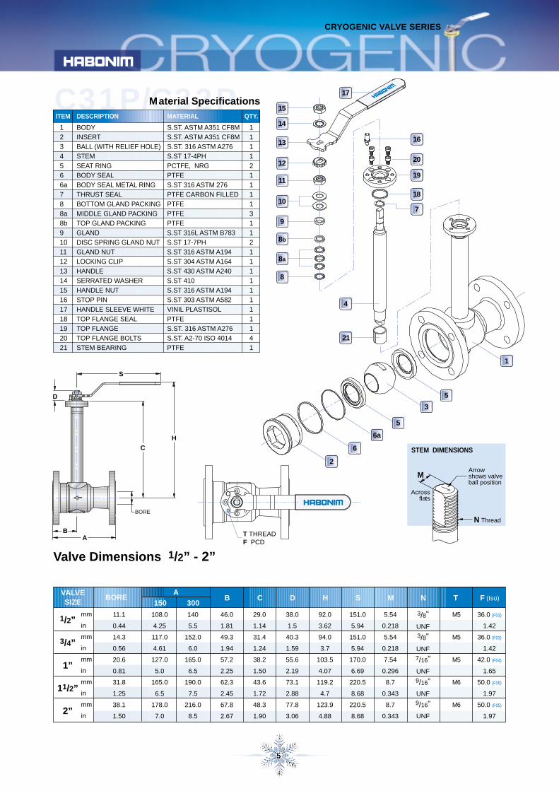
C31P/C32PMaterial Specifications
2
6
5
3
5
1
18
14
5
1234566a788a8b9101112131415161718192021
BODYINSERTBALL (WITH RELIEF HOLE)STEMSEAT RINGBODY SEALBODY SEAL METAL RINGTHRUST SEALBOTTOM GLAND PACKINGMIDDLE GLAND PACKINGTOP GLAND PACKINGGLANDDISC SPRING GLAND NUTGLAND NUTLOCKING CLIPHANDLESERRATED WASHERHANDLE NUTSTOP PINHANDLE SLEEVE WHITETOP FLANGE SEALTOP FLANGETOP FLANGE BOLTSSTEM BEARING
S.ST. ASTM A351 CF8MS.ST. ASTM A351 CF8MS.ST. 316 ASTM A276S.ST 17-4PHPCTFE, NRGPTFES.ST 316 ASTM 276PTFE CARBON FILLEDPTFEPTFEPTFES.ST 316L ASTM B783S.ST 17-7PHS.ST 316 ASTM A194S.ST 304 ASTM A164S.ST 430 ASTM A240S.ST 410S.ST 316 ASTM A194S.ST 303 ASTM A582VINIL PLASTISOLPTFES.ST. 316 ASTM A276S.ST. A2-70 ISO 4014PTFE
111121111311211111111141
ITEM DESCRIPTION MATERIAL QTY.
Valve Dimensions 1/2” - 2”
T THREADF PCD
7
VALVESIZE
BOREA
mm
in
mm
in
mm
in
mm
in
mm
in
1/2”
3/4”
1”
11/2”
2”
108.0
4.25
117.0
4.61
127.0
5.0
165.0
6.5
178.0
7.0
140
5.5
152.0
6.0
165.0
6.5
190.0
7.5
216.0
8.5
46.0
1.81
49.3
1.94
57.2
2.25
62.3
2.45
67.8
2.67
29.0
1.14
31.4
1.24
38.2
1.50
43.6
1.72
48.3
1.90
38.0
1.5
40.3
1.59
55.6
2.19
73.1
2.88
77.8
3.06
92.0
3.62
94.0
3.7
103.5
4.07
119.2
4.7
123.9
4.88
151.0
5.94
151.0
5.94
170.0
6.69
220.5
8.68
220.5
8.68
5.54
0.218
5.54
0.218
7.54
0.296
8.7
0.343
8.7
0.343
3/8"
UNF3/8"
UNF7/16"
UNF9/16"
UNF9/16"
UNF
36.0 (F03)
1.42
36.0 (F03)
1.42
42.0 (F04)
1.65
50.0 (F05)
1.97
50.0 (F05)
1.97
150 300B C D H S M N
11.1
0.44
14.3
0.56
20.6
0.81
31.8
1.25
38.1
1.50
15
13
12
11
10
9
8b
8a
8
4
21
17
19
20
16
6a
S
H
C
AB
BORE
CRYOGENIC VALVE SERIES
Arrowshows valveball position
N Thread
M
Acrossflats
STEM DIMENSIONS
D
T
M5
M5
M5
M6
M6
F (Iso)
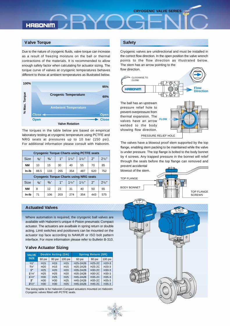
Actuated Valves
6
CRYOGENIC VALVE SERIES
Where automation is required, the cryogenic ball valves areavailable with Habonim’s unique 4-Piston pneumatic Compactactuator. The actuators are availbale in spring return or doubleacting. Limit switches and positioners can be mounted on theactuator top face according to NAMUR or ISO bolt patterninterface. For more information please refer to Bulletin B-310.
The valves have a blowout proof stem supported by the top
flange, enabling stem packing to be maintained while the valve
is under pressure. The top flange is bolted to the body bonnet
by 4 screws. Any trapped pressure in the bonnet will relief
through the seals before the top flange can removed and
prevent accidental
blowout of the stem.
Safety
Cryogenic valves are unidirectional and must be installed inthe correct flow direction. In the open position the valve wrenchpoints to the flow direction as i l lustrated below.The stem has an arrow pointing to theflow direction.
The ball has an upstreampressure relief hole toprevent overpressure fromthermal expansion. Thevalves have an arrowwelded to the bodyshowing flow direction.
PRESSURE RELIEF HOLE
The torques in the table below are based on empiricallaboratory testing at cryogenic temperature using PCTFE andNRG seats at pressures up to 10 bar (150 psi).For additional information please consult with Habonim.
Due to the nature of cryogenic fluids, valve torque can increase
as a result of freezing moisture on the ball or thermal
contractions of the materials. It is recommended to allow
enough safety factor when calculating for actuator sizing. The
torque curve of valves at cryogenic temperatures behaves
different to those at ambient temperatures as illustrated below.
Valve Rotation
95%
Ambeient Temperature
Crogenic Temperature60%
Close Open
100%
Close
% M
ax. T
orq
ue
Open
Valve Actuator Sizing
The sizing table is for Habonim Compact actuators mounted on HabonimCryogenic valves fitted with PCTFE seats.
Valve Torque
1/2” 3/4” 11/4"
Cryogenic Torque Charts using NRG seats
11/2" 2" 21/2"1"Size
8
71
12
106
23
203
31
274
40
354
50
443
65
575
NM
In-lb
1/2” 3/4” 11/4"
Cryogenic Torque Charts using PCTFE seats
11/2" 2" 21/2"1"Size
10
88.5
15
133
30
265
40
354
55
487
70
620
85
752
NM
In-lb
TOP FLANGE
BODY BONNET
TOP FLANGESCREWS
FLOW
FlowDirection
CLOCKWISE TOCLOSE
VALVESIZE
1/2"3/4"1"
11/4"11/2"
2"21/2"
60 psi 80 psi
H15H20H25H25H30H30H30
60 psi 80 psi
H15H15H20H25H25H30H30
H25-2A2BH25-2A2BH35-2A2BH35-2A2BH45-2A2BH45-2A2BH45-2A2B
H25-2CH25-2CH30-2CH30-2CH35-2CH35-2CH45-2C
100 psi
H20-3H20-3H30-3H30-3H35-3H35-3H35-3
100 psi
H15H15H20H20H25H25H25
Double Acting (DA) Spring Return (SR)
7
CRYOGENIC VALVE SERIES
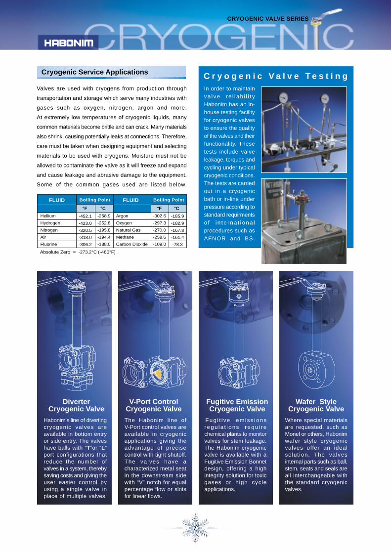
In order to maintain
va lve re l i ab i l i t y
Habonim has an in-
house testing facility
for cryogenic valves
to ensure the quality
of the valves and their
functionality. These
tests include valve
leakage, torques and
cycling under typical
cryogenic conditions.
The tests are carried
out in a cryogenic
bath or in-line under
pressure according to
standard requirments
o f i n te rna t i ona l
procedures such as
AFNOR and BS.
C r y o g e n i c V a l v e T e s t i n gValves are used with cryogens from production through
transportation and storage which serve many industries with
gases such as oxygen, nitrogen, argon and more.
At extremely low temperatures of cryogenic liquids, many
common materials become brittle and can crack. Many materials
also shrink, causing potentially leaks at connections. Therefore,
care must be taken when designing equipment and selecting
materials to be used with cryogens. Moisture must not be
allowed to contaminate the valve as it will freeze and expand
and cause leakage and abrasive damage to the equipment.
Some of the common gases used are listed below.
Cryogenic Service Applications
Habonim’s line of divertingcryogenic valves areavailable in bottom entryor side entry. The valveshave balls with “T”or “L”port configurations thatreduce the number ofvalves in a system, therebysaving costs and giving theuser easier control byusing a single valve inplace of multiple valves.
DiverterCryogenic Valve
The Habonim line ofV-Port control valves areavailable in cryogenicapplications giving theadvantage of precisecontrol with tight shutoff.The valves have acharacterized metal seatin the downstream sidewith “V” notch for equalpercentage flow or slotsfor linear flows.
V-Port ControlCryogenic Valve
Fug i t i ve emiss ionsregu la t i ons requ i rechemical plants to monitorvalves for stem leakage.The Habonim cryogenicvalve is available with aFugitive Emission Bonnetdesign, offering a highintegrity solution for toxicgases or high cycleapplications.
Fugitive EmissionCryogenic Valve
Wafer StyleCryogenic Valve
Where special materialsare requested, such asMonel or others, Habonimwafer style cryogenicvalves offer an idealsolution. The valvesinternal parts such as ball,stem, seats and seals areall interchangeable withthe standard cryogenicvalves.
Absolute Zero = -273.2°C (-460°F)
Boiling Point Boiling Point
Hellium
Hydrogen
Nitrogen
Air
Fluorine
°F °C
-452.1
-423.0
-320.5
-318.0
-306.2
-268.9
-252.8
-195.8
-194.4
-188.0
Argon
Oxygen
Natural Gas
Methane
Carbon Dioxide
°F °C
FLUID
-302.6
-297.3
-270.0
-258.6
-109.0
-185.9
-182.9
-167.8
-161.4
-78.3
FLUID

Identification Code
ISS
UE
00
- 01
/03
In accordance with our policy to strive for continuous improvement of the product, we reserve the right to alter the dimensions, technical data and information included in this catalogue when required.
Kfar Hanassi, Upper Galilee 1, 12305 Israel
E-Mail: h a b o n i m @ h a b o n i m . c o . i lF a x : 9 7 2 - 4 - 6 9 1 4 9 0 2
T e l : 9 7 2 - 4 - 6 9 1 4 9 1 1
w w w . h a b o n i m . c o m
5
AB
*CD
FLNOS
V
AntistaticFull boreCryogenicDiverterbottom entryFiresafeLet LokControlOxygenDiverterside entryVacuum
BODY / END
BALL / STEM
15678
BronzeBrassS. St. 316 (L)MonelS. St. 304
SERIES
CPM
PCTFENRGMetal
I
G
M
T
GraphiteImpregnatedGraphiteReinforcedS. St O-RingPTFE coatedPTFE
SEAT
SEAL
END CONNECTION **
1 2
1 0
SIZE
3 4 5
C
SERVICE
6 7 8
4 7 P
SERIES
10 11
BODYEND
66
12 13
BALLSTEM
M6
14 15
SEATSEAL
TC
17 18 19 20
END TYPE
B S P
21 22 . . . 30
SPECIAL APPLICATION
9 16
//
T
The HABONIM Cryogenic Ball Valve Identification Code
* When using the prefix “C” the valve will always have a ball with pressure relief hole on the upstream side.** Other end connections are available on request.
02
03
05
07
10
12
15
20
25
SIZE
Inch mmCode
BSPTDINNPTBW
XBWSWXSWBWOETOSWOKLMETBLLLMPN40
BS 21DIN 2999 (BSPP)B1.20.1ButtweldSch 5,10, 40, 80Extended ButtweldSocketweldExtended Socket WeldOD tubeExtended OD tubeSocketweld OD tubeCopper tubeExtended Copper tubeLet Lok (Inch)Let Lok (Metric)Flanged DIN PN40/F1
1/4"
3/8"
1/2"
3/4"
1"
11/4"
11/2"
2"
21/2"
8
10
15
20
25
32
40
50
65
SERVICE
47
313273
74
78
StandardISO padANSI 150#ANSI 300#ANSI 150#Full BoreANSI 300#Full BoreDIN PN40Full Bore
6M78
S. St. 316S. St. 17-4PHMonelS. St. 304
Habonim cryogenic valves are identified by the prefix “C”.When placing an order for HABONIM cryogenic valves, it isessential to provide as many details possible on the applicationsuch as: media, temperature, pressure, pipe line size andtype of connection. Refer to the Habonim Code System forfurther details.Example: 10 C47P - 666MCT / BWSize 1" (10), Cryogenic (C), 3-piece (47P), S. St Body (6)S. St Ends (6), S. St Ball (6), 17-4PH Stem (M), PCTFESeats (C), PTFE Body Seals (T), Buttweld ends (BW).
Special Application
Diverter ball valve90° turnDiverter ball valve180° turnBall with upstreampressure reliefhole
FEV60KEP
Fugitive EmissionControl valve seatLLP Locking deviceElectro Polish
90°
180°
P250
How to order
CRYOGENIC VALVE SERIES