Embed Size (px)
Citation preview
CrossPoint Plus Series Matrix Switchers“Single-Box” Solutions for Ultra-WidebandRouting Applications
Imagine this scenario: you’re off-site, but you need to
monitor the activities of your matrix switching system.
How would you do that?
continued on page 2
If you’ve installed an ExtronCrossPoint Plus Matrix Switcher,then you can take advantage of itsinnovative Digital Sync ValidationProcessing (DSVP) feature.
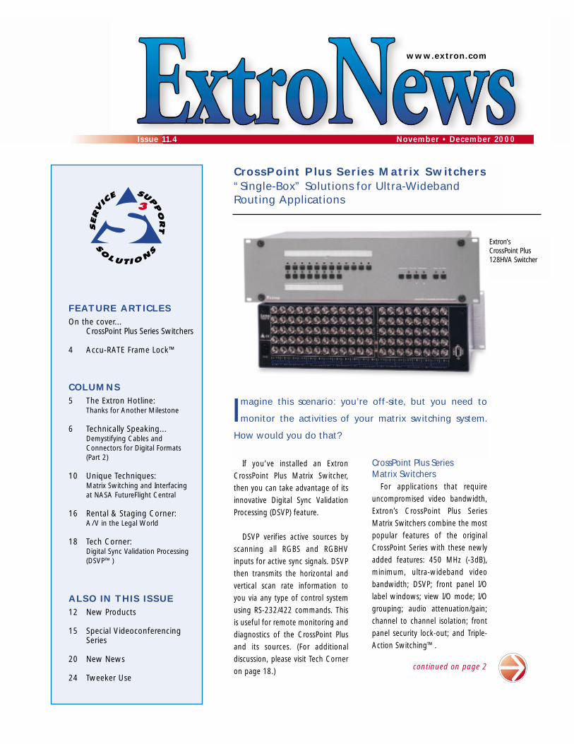
DSVP verifies active sources byscanning all RGBS and RGBHVinputs for active sync signals. DSVPthen transmits the horizontal andvertical scan rate information toyou via any type of control systemusing RS-232/422 commands. Thisis useful for remote monitoring anddiagnostics of the CrossPoint Plusand its sources. (For additionaldiscussion, please visit Tech Corneron page 18.)
www.extron.com
FEATURE ARTICLESOn the cover...
CrossPoint Plus Series Switchers
4 Accu-RATE Frame Lock™
COLUMNS5 The Extron Hotline:
Thanks for Another Milestone
6 Technically Speaking...Demystifying Cables andConnectors for Digital Formats(Part 2)
10 Unique Techniques:Matrix Switching and Interfacing at NASA FutureFlight Central
16 Rental & Staging Corner:A/V in the Legal World
18 Tech Corner:Digital Sync Validation Processing(DSVP™)
ALSO IN THIS ISSUE12 New Products
15 Special VideoconferencingSeries
20 New News
24 Tweeker Use
CrossPoint Plus Series Matrix Switchers
For applications that requireuncompromised video bandwidth,Extron’s CrossPoint Plus SeriesMatrix Switchers combine the mostpopular features of the originalCrossPoint Series with these newlyadded features: 450 MHz (-3dB),minimum, ultra-wideband videobandwidth; DSVP; front panel I/Olabel windows; view I/O mode; I/Ogrouping; audio attenuation/gain;channel to channel isolation; frontpanel security lock-out; and Triple-Action Switching™.
Issue 11.4 November • December 2000
Extron’s CrossPoint Plus128HVA Switcher
2 ExtroNews 11.4 November/December 2000
C r o s s P o i n t P l u s S e r i e s S w i t c h e r s ( c o n t . )
output selection. It’s easy to label the frontpanel I/O buttons; just use any Brother P-Touch labeler or Extron’s label software,which ships with every Extron matrixswitcher. For added convenience, the viewI/O mode allows you to easily see whichindividual inputs and outputs are activelyconnected. This mode is available from thefront panel or through RS-232/422.
To make installation and control eveneasier, I/O grouping allows the matrix to bevirtually divided into smaller sub-switchers.This feature allows specific outputs—such asthose designated for a specific videoformat—to be grouped together forconvenient wiring and switching. And tosave time, the CrossPoint Plus Series providesglobal presets, which are individual I/Oconfigurations. These allow you to set up I/Oconfigurations and recall them from memoryfor future use. Use either the front panel orRS-232/422 to save and recall your globalpresets.
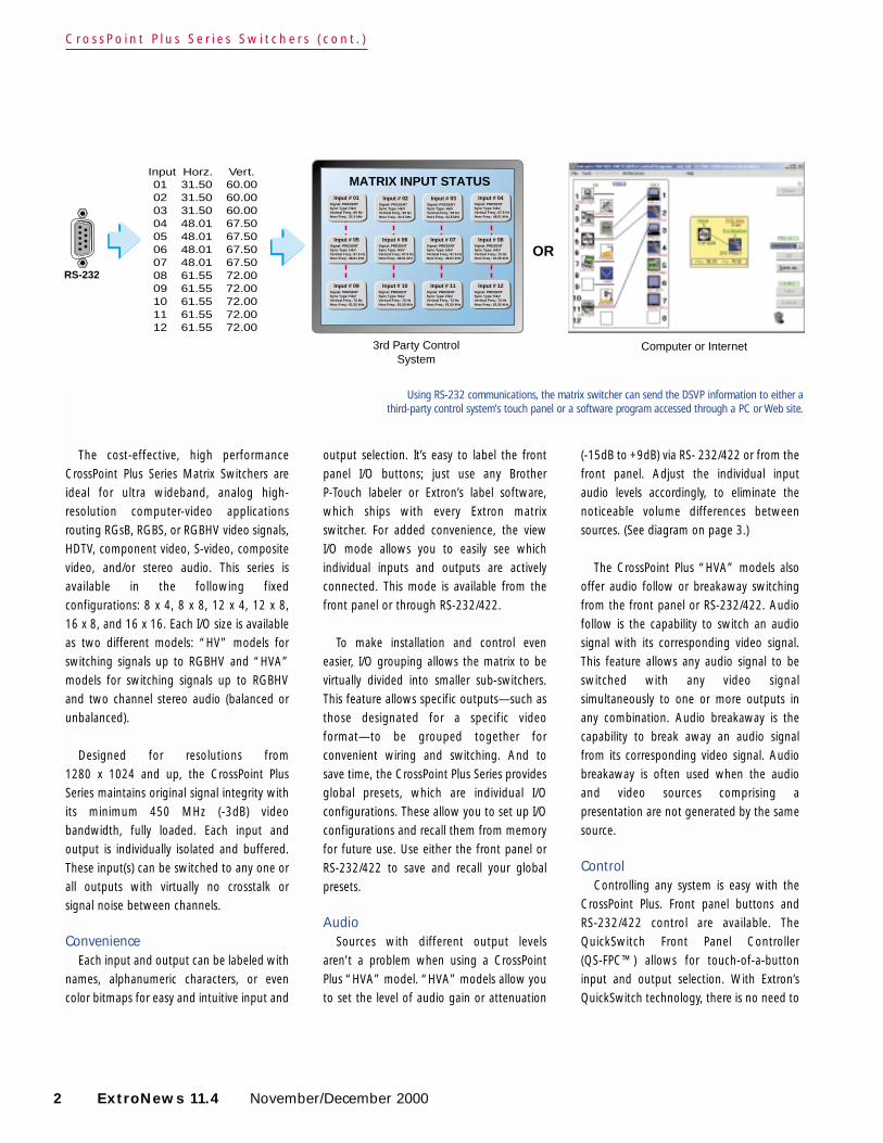
AudioSources with different output levels
aren’t a problem when using a CrossPointPlus “HVA” model. “HVA” models allow youto set the level of audio gain or attenuation
(-15dB to +9dB) via RS- 232/422 or from thefront panel. Adjust the individual inputaudio levels accordingly, to eliminate thenoticeable volume differences betweensources. (See diagram on page 3.)
The CrossPoint Plus “HVA” models alsooffer audio follow or breakaway switchingfrom the front panel or RS-232/422. Audiofollow is the capability to switch an audiosignal with its corresponding video signal.This feature allows any audio signal to beswitched with any video signalsimultaneously to one or more outputs inany combination. Audio breakaway is thecapability to break away an audio signalfrom its corresponding video signal. Audiobreakaway is often used when the audioand video sources comprising apresentation are not generated by the samesource.
ControlControlling any system is easy with the
CrossPoint Plus. Front panel buttons and RS-232/422 control are available. TheQuickSwitch Front Panel Controller (QS-FPC™) allows for touch-of-a-buttoninput and output selection. With Extron’sQuickSwitch technology, there is no need to
The cost-effective, high performanceCrossPoint Plus Series Matrix Switchers areideal for ultra wideband, analog high-resolution computer-video applicationsrouting RGsB, RGBS, or RGBHV video signals,HDTV, component video, S-video, compositevideo, and/or stereo audio. This series isavailable in the following fixedconfigurations: 8 x 4, 8 x 8, 12 x 4, 12 x 8,16 x 8, and 16 x 16. Each I/O size is availableas two different models: “HV” models forswitching signals up to RGBHV and “HVA”models for switching signals up to RGBHVand two channel stereo audio (balanced orunbalanced).
Designed for resolutions from 1280 x 1024 and up, the CrossPoint PlusSeries maintains original signal integrity withits minimum 450 MHz (-3dB) videobandwidth, fully loaded. Each input andoutput is individually isolated and buffered.These input(s) can be switched to any one orall outputs with virtually no crosstalk orsignal noise between channels.
ConvenienceEach input and output can be labeled with
names, alphanumeric characters, or evencolor bitmaps for easy and intuitive input and
RS-232
Input Horz. Vert.01 31.50 60.0002 31.50 60.0003 31.50 60.0004 48.01 67.50 05 48.01 67.5006 48.01 67.5007 48.01 67.5008 61.55 72.0009 61.55 72.0010 61.55 72.0011 61.55 72.0012 61.55 72.00
3rd Party ControlSystem
Computer or Internet
MATRIX INPUT STATUSInput # 01
Signal: PRESENTSync Type: H&VVertical Freq.: 60 Hz Horz Freq.: 31.5 kHz
Input # 02Signal: PRESENTSync Type: H&VVertical Freq.: 60 Hz Horz Freq.: 31.5 kHz
Input # 03Signal: PRESENTSync Type: H&VVertical Freq.: 60 Hz Horz Freq.: 31.5 kHz
Input # 04Signal: PRESENTSync Type: H&VVertical Freq.: 67.5 Hz Horz Freq.: 48.01 kHz
Input # 05Signal: PRESENTSync Type: H&VVertical Freq.: 67.5 Hz Horz Freq.: 48.01 kHz
Input # 06Signal: PRESENTSync Type: H&VVertical Freq.: 67.5 Hz Horz Freq.: 48.01 kHz
Input # 07Signal: PRESENTSync Type: H&VVertical Freq.: 67.5 Hz Horz Freq.: 48.01 kHz
Input # 08Signal: PRESENTSync Type: H&VVertical Freq.: 72 Hz Horz Freq.: 61.55 kHz
Input # 09Signal: PRESENTSync Type: H&VVertical Freq.: 72 Hz Horz Freq.: 61.55 kHz
Input # 10Signal: PRESENTSync Type: H&VVertical Freq.: 72 Hz Horz Freq.: 61.55 kHz
Input # 11Signal: PRESENTSync Type: H&VVertical Freq.: 72 Hz Horz Freq.: 61.55 kHz
Input # 12Signal: PRESENTSync Type: H&VVertical Freq.: 72 Hz Horz Freq.: 61.55 kHz
OR
Using RS-232 communications, the matrix switcher can send the DSVP information to either a third-party control system’s touch panel or a software program accessed through a PC or Web site.
keypad and/or the MCP 1000 remotecontrol panel. Both remote control optionsare easy to use and provide tactile buttonsfor quick selection. Use an MCP 1000 forone-button switching to a particular outputand selecting global presets, or use an MKP1000 to select a different input or preset.
SecurityThe CrossPoint Plus Series provides
excellent isolation between channels andextremely low electromagnetic emissions.This security feature is perfect forminimizing signal leakage in high securityor government environments.
If a CrossPoint Plus Series MatrixSwitcher is installed in an unsecuredenvironment, you can take advantage ofthe executive mode (security lock-out)option. While in the executive mode, aspecial button combination is required tooperate the front panel controller. Thisfeature restricts access to users who knowthe security passcode, so unauthorizedand/or inexperienced users can’t changeany of the settings.
November/December 2000 ExtroNews 11.4 3
Audio Inputs
VCR
No noticeable volumedifferences between sources
Audio System
CD Jukebox
CrossPoint Plus Series Switcher
I/OCONTROL
CROSSPOINT Plus MATRIX SERIES SWITCHER with DSVPTM
0-3-6-9
-12-15
Low AudioOutput Level
369
1215
+4+1-2-5-8
-12
+7+10+13+16+19
VUdBu
0-3-6-9
-12-15
OutputLevel
369
1215
+4+1-2-5-8
-12
+7+10+13+16+19
VUdBu
0-3-6-9
-12-15
High AudioOutput Level
369
1215
+4+1-2-5-8
-12
+7+10+13+16+19
VUdBu
conquer a steep learning curve whenmastering the I/O routing control of a matrixswitcher. The intuitive QS-FPC uses a tactilefront panel button for each input andoutput. For any routing changes, just push abutton to select or deselect its input sourceor output destination.
Extron’s Simple Instruction Set™ is provided for RS-232 control via Extron’s Windows-based control/virtualizationsoftware or a third-party control system. ForRS-232/422 remote control from a PC,Extron ships our Windows-based controlsoftware with every matrix switcher. Thisicon-driven software uses a graphical, drag-and-drop interface to make I/O configurationand other customization functions simpleand convenient. It also offers an emulationmode for configuration of an off-site matrixswitcher. You can then save the I/Oconfiguration for future downloading to thematrix switcher, which also saves time andcosts during the install.
Additional remote control conveniencemay be provided by the MKP 1000 remote
The CrossPoint Plus allowsyou to adjust the audiogain/attenuation for eachinput, so volume levels areconsistent across all sources.
And more…Extron’s exclusive Triple-Action Switching,
also known as RGB delay, eliminates glitchesduring switching. Triple-Action Switchingmutes the output to the display when thematrix switcher switches to a new source.
Each CrossPoint Plus Series MatrixSwitcher is housed in a rack-mountable, 19"wide enclosure, and the 100-240 volt, auto-switchable, internal power supply providesworldwide power compatibility.
The CrossPoint Plus Series offers off-the-shelf, in-stock, single-box solutions to routingapplications requiring uncompromised videobandwidth. When the best matrix for yourparticular application is required, theCrossPoint Plus Series delivers the highestperformance and most cost-effectivesolution.
Please call Extron for part numbers andpricing information.
4 ExtroNews 11.4 November/December 2000
Picture this: in preparation for anannual investors’ meeting, you’ve justfinished setting up several video sources:a switcher, scaler, and displays or projectors at the Widget Worldcorporate headquarters. Everything isgoing smoothly and the system design isnearly ideal. You’re testing the systemwhen the Widget World CEO stops by totake a look. You switch to the input froma video camera, which your assistantpans across the boardroom. To yourembarrassment, the CEO notices that thesystem has a glitch: a severe case of videohiccups, which must be cured beforetomorrow’s meeting.
Image Tearing: When Frame Rate Conversion Goes Bad
You have probably seen this situationbefore. The video “hiccupping” is known asan image tear—a transient ripple, blip, orfreeze in a scaled video image. It is acommon byproduct of scaling that is mostnoticeable in video that has motionelements, particularly when a video camerapans across a scene or someone movesquickly across the camera’s view.
Image tearing is an artifact of frame rateconversion. Scalers convert video input ofone format and resolution (such as NTSC orPAL interlaced video or RGB at 560 x 384 at59.94 Hz) into output of another format andrefresh rate (perhaps progressively scanned
RGB at 1024 x 768 at 60 Hz). To convertframe rates, a scaler must create or combineframes.
An image tear occurs if the input framerate is slower or faster than the output framerate, and part of the old frame and part ofthe new frame are displayed at the sametime during a refresh cycle.
The Solution: Accu-RATE Frame Lock (patent pending)
If the output frame rate can be matchedexactly to the frame rate of the input with themost motion content, image tears can beeliminated completely. The Extron Accu-RATEFrame Lock (AFL™) (patent pending) sets andlocks the output rate to the input rate.
In the SGS 408, the scaler outputs videofrom all inputs in the selected format, but at arefresh rate identical to that of a designatedinput (input #1). The result is a completelytear-free output in a seamless switchingsystem with a fixed video delay of only 1/4 frame. For other inputs here's whathappens: still video is not affected becausethere is no visible change in frames. If youwant to use multiple motion video inputs,such as several cameras, each of those inputsshould be genlocked together for optimalperformance. The SGS 408 can be used inapplications where completely tear-freemotion video must be output with glitch-freeswitching in a system containing both still andmotion sources.
The System 7SC can be set up with adifferent video type (motion or still forms ofcomposite video, S-video, component video,or RGB) and a different refresh rate for eachinput without any need for genlocking motionvideo sources. In the System 7SC, Accu-RATEFrame Lock locks the output frame rate to therate of the active input, which can be any oneof the scaled (non-RGB) inputs.
Accu-RATE Frame Lock is unique to theseExtron products; this feature is not availableanywhere else.
Accu-RATE Frame Lock™
Image tearing caused by mismatched refresh rates
System 7SC
SGS 408RCP 1000(Remote Control Panel)
ECP 1000(Event Control Panel)
component of our organization—sales,product development, engineering, andmanufacturing.
Many of us here at Extron can rememberwhen our entire manufacturing facilityoccupied what is now a world-class trainingcenter for A / V professionals—the S3
Technical Institute. Today, Extron requiresthree separate buildings to house all of ourAnaheim operations. One building isdedicated to sales, marketing, and training;the second is dedicated to manufacturing;and this new facility houses our productdevelopment, engineering, and tradeshowdepartments.
To us, this move is a significant milestonefor several reasons. One, it symbolizeshealthy growth for both the industry as awhole and for us as a company. It also meanswe will be able to dedicate even moreresources to training, engineering, andproduct development and to meeting theincreasing demand for constantly evolvingproduct designs. Most importantly, the newbuilding represents opportunities for Extronto expand our level of service, support, andsolutions that we can offer to help yourbusiness succeed.
Extron owes our growth to the supportand commitment of the dealers andconsultants who work with our products,and we would like to extend our mostsincere thanks to you all for yourcontributions to Extron’s success. We intendto put our new facility to full use in order toensure Extron continues to offer you the bestsolutions and support available in theindustry.
As always, please feel free to contact yourExtron Customer Support Representativewith any recommendations or insights youmay have on how we can further improveour commitment to your business. Andthanks again for another milestone.
November/December 2000 ExtroNews 11.4 5
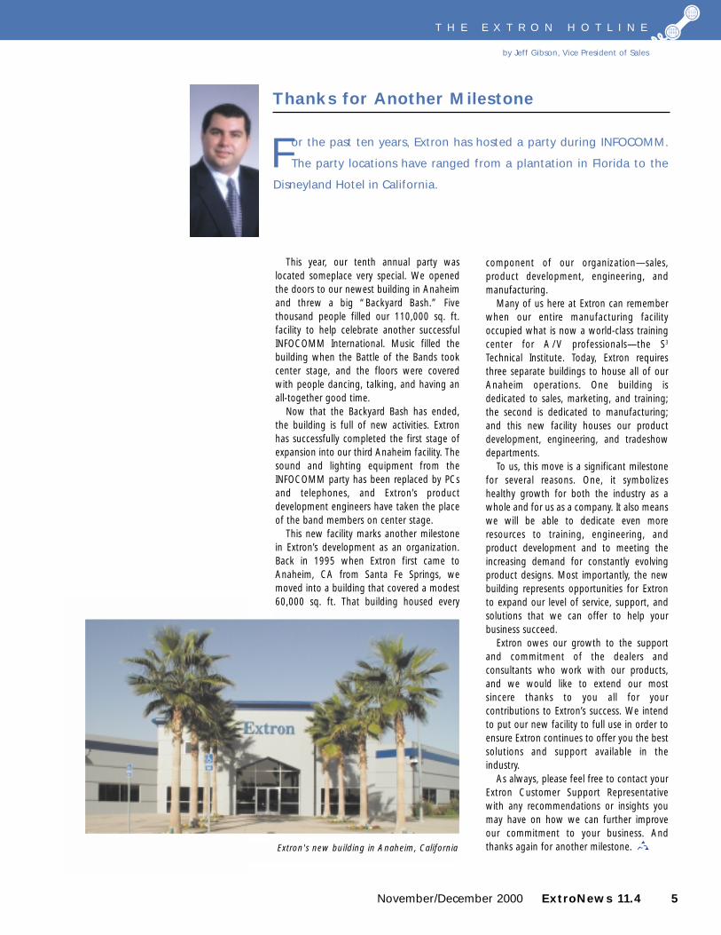
This year, our tenth annual party waslocated someplace very special. We openedthe doors to our newest building in Anaheimand threw a big “Backyard Bash.” Fivethousand people filled our 110,000 sq. ft.facility to help celebrate another successfulINFOCOMM International. Music filled thebuilding when the Battle of the Bands tookcenter stage, and the floors were coveredwith people dancing, talking, and having anall-together good time.
Now that the Backyard Bash has ended,the building is full of new activities. Extronhas successfully completed the first stage ofexpansion into our third Anaheim facility. Thesound and lighting equipment from theINFOCOMM party has been replaced by PCsand telephones, and Extron’s productdevelopment engineers have taken the placeof the band members on center stage.
This new facility marks another milestonein Extron’s development as an organization.Back in 1995 when Extron first came toAnaheim, CA from Santa Fe Springs, wemoved into a building that covered a modest60,000 sq. ft. That building housed every
For the past ten years, Extron has hosted a party during INFOCOMM.
The party locations have ranged from a plantation in Florida to the
Disneyland Hotel in California.
Thanks for Another Milestone
T H E E X T R O N H O T L I N E
by Jeff Gibson, Vice President of Sales
Extron's new building in Anaheim, California
6 ExtroNews 11.4 November/December 2000
bundle. When the DVI specification is
extended to the dual mode operation,
greater data rates for higher display
resolutions are possible, but now there
are seven parallel differential, high-speed
pairs. Cabling and connection become
extremely important. In this way, DVI is
similar to the original D1 parallel interface
which requires eight or ten differentially
driven serial lines capable of handling a
full byte on each clock cycle. If you have
the opportunity, take a look at available
D1 cables, and you will find them limited
in usable lengths—very much like DVI.
The nominal DVI cable length limit is
4.6 meters (about 15 feet). Electrical
performance requirements are similar to
serial digital. Signal risetime (0.330
nanoseconds), cable impedance (100
ohms), far end crosstalk (FEXT) of no
more than 5%, and signal risetime
degradation (160 picoseconds maximum)
are the key parameters highlighted in the
DVI specification regarding the physical
connection. Cable for DVI is application
specific because maintaining these
specifications is no easy feat since the
actual bit rate per channel is 1.65 Gbps.
And, we’re talking twisted pair
cable here.
Firewire, or IEEE-1394, is that tiny,
square-like connector tucked away on the
side of your digital camcorder that allows
you to upload DV format to your
computer, among other things. And as we
approach the real beginning of the
millennium (2001), USB is receiving a
major overhaul…analogous to jacking up
your radiator cap and driving in a new car
underneath it. Yes, USB 2.0 promises to
bring us hot swappable, hosted
peripherals now capable of talking at 480
Mbps instead of just 12 Mbps.
Getting From Here To There With DVI
The DVI (Digital Visual Interface)
connection between local monitors and
computers presents an interesting
interfacing environment. It is a
combination serial digital interface and a
parallel interface format, somewhat like
combining the broadcast serial digital and
parallel digital interfaces.
Transmission of the TMDS (transition
minimized differential signaling) format
combines four differential, high-speed
serial connections (in its base
configuration) transmitted in a parallel
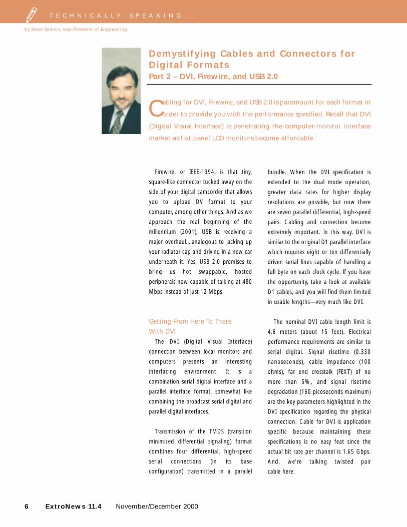
Demystifying Cables and Connectors forDigital FormatsPart 2 – DVI, Firewire, and USB 2.0
T E C H N I C A L L Y S P E A K I N G . . .
by Steve Somers, Vice President of Engineering
Cabling for DVI, Firewire, and USB 2.0 is paramount for each format in
order to provide you with the performance specified. Recall that DVI
(Digital Visual Interface) is penetrating the computer-monitor interface
market as flat panel LCD monitors become affordable.
November/December 2000 ExtroNews 11.4 7
Those of you familiar with CAT 5, CAT
5e, CAT 6, and CAT 7 (I feel like someone
with too many cats), know the importance
of cable and installation quality in order to
meet performance. For CAT 6, the industry
is talking 1 Gbps over four twisted pair
wires over a distance of 100 meters.
Sound something like DVI in terms of pairs
and speed? And, the trend is to push for
faster communication speeds. This makes
these methods very similar in speed with
DVI, but that’s where the similarity ends. In
high-speed data communications systems,
there is significant overhead added to
handle error correction. And, if some data
is lost, it can be re-sent. With digital video
interfaces like DVI, there is some error
correction facility, but the delivery is a one-
way street. If you fail to receive all the data
bits required to make the system work,
you lose picture information or lose the
picture completely.
So, the DVI cable and its termination is
very important. The physical parameters of
the twisted pairs must be highly
controlled. Specifications for the cable and
the receiver are given in fractions of bit
transmission time. Therefore, the
requirements depend on the clock rate or
signal resolution being used. Transferring
the maximum rate (1600 x 1200 at 60 Hz)
for a single link system means that one bit
time (10 bits per pixel) is 0.1(1/165 MHz),
which is only 0.606 nanoseconds. Ten bit
times describe one pixel in this system.
The DVI receiver specification allows
only 0.40 x bit time, or about 0.242
nanoseconds intra-pair skew (within the
twisted pair). Remember, this is differential
transmission. The “eye” pattern seen at
the receiver end must be as symmetrical as
possible. Further, the inter-pair skew,
which governs how bits will line up in time
at the receiving decoder, may only be 0.6 x
pixel time, or 3.64 nanoseconds. These
parameters are largely responsible for the
short transmission distances for DVI.
In addition to the above requirements, a
cable for DVI should be evaluated on its
insertion loss for a given length. The DVI
transmitter output eye pattern is specified
into a nominal cable impedance of 100
ohms. A normal signal swings +780 mV to
–780 mV. The minimum positive signal
swing is +200 mV and the minimum
negative swing is –200 mV (total swing of
400 mV). When the signals are combined
in the differential receiver, the resulting
signal level is two times the swing value.
But, for the cable situation, we must
assume minimum performance on the
transmitter side and best sensitivity on the
receiver end. The receiver must operate on
signals as low as +75 mV to –75 mV, or a
total swing of 150 mV. This means that
under worst-case conditions, the cable
attenuation can be no more than 8.5dB at
1.65 GHz (10 bits/pixel times 165 MHz
clock). As you can imagine, maintaining
this type of performance on twisted pair
wires is relatively difficult.
DVI Connector – All For One andTwo For All
Two versions of the connector emerged
from its creator—the DDWG (Digital
Display Working Group; more details and
full specs at www.ddwg.org). The DDWG
felt that the transitions from analog to
continued on next page
T E C H N I C A L L Y S P E A K I N G . . .
digital monitor interfacing should be
gradual with capability to support the
analog VGA for some time. Therefore,
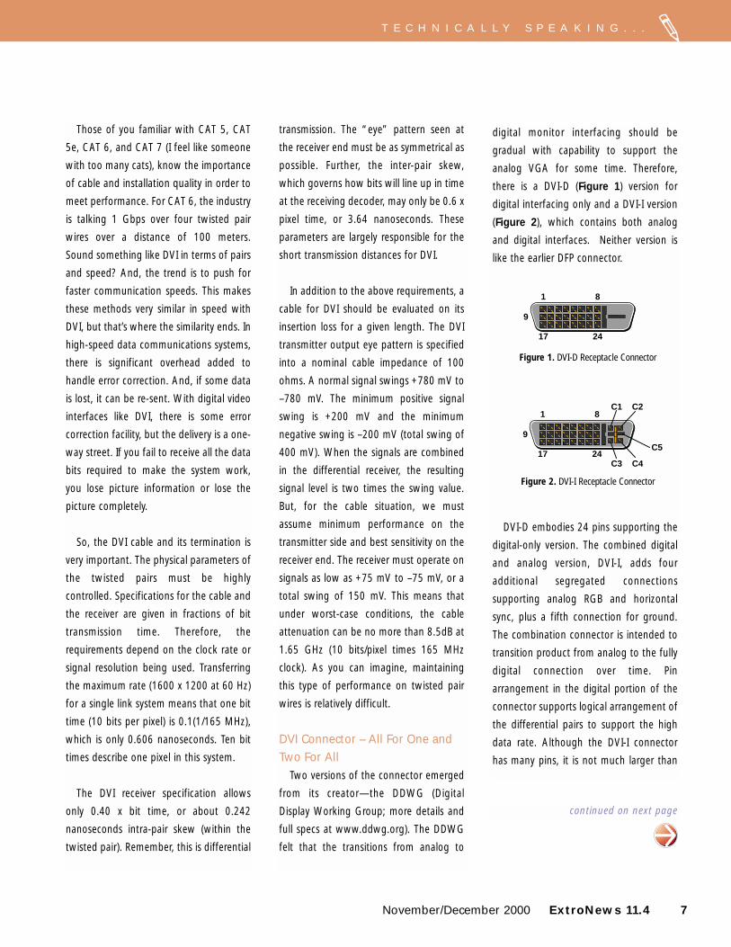
there is a DVI-D (Figure 1) version for
digital interfacing only and a DVI-I version
(Figure 2), which contains both analog
and digital interfaces. Neither version is
like the earlier DFP connector.
DVI-D embodies 24 pins supporting the
digital-only version. The combined digital
and analog version, DVI-I, adds four
additional segregated connections
supporting analog RGB and horizontal
sync, plus a fifth connection for ground.
The combination connector is intended to
transition product from analog to the fully
digital connection over time. Pin
arrangement in the digital portion of the
connector supports logical arrangement of
the differential pairs to support the high
data rate. Although the DVI-I connector
has many pins, it is not much larger than
1
9
8
17 24
DVI-D Receptacle Connector
1
9
8C1 C2
C3 C4
C517 24
DVI-I Receptacle Connector
Figure 1. DVI-D Receptacle Connector
Figure 2. DVI-I Receptacle Connector
Power supply(8 to 40 V. maximum DC current: 1.5 A)
Cable shielding
Signal line shield
Twisted pair signallines: two sets
Figure 5. IEEE 1394 Cable
8 ExtroNews 11.4 November/December 2000
the current 15-pin HD VGA connector.
Currently, termination of the connector is
challenging due to the tooling and limited
space within the assembly. The DVI
connector is allowed a maximum of 0.160
nanoseconds risetime degradation to the
signal.
DV and Firewire – Serial Digital forthe Rest of Us
The new DV, or Digital Video, recording
standard now driving most consumer
camcorder purchases, is a serial digital
format of 25 Mbps, sometimes called
DV25. The Firewire (IEEE 1394) interface
conveniently handles the data rate of DV,
and then some. The DV format is the first
application making tremendous use of the
IEEE 1394 capability. IEEE 1394 is much
bigger than DV in terms of data handling.
This specification supports up to 400 Mbps
currently and extensions to the standard
are under consideration. Its key strengths
are its “just-in-time” data delivery and
peer-to-peer relationship…meaning that
Firewire appliances can communicate
without need for a host controller.
So, when we talk DV, we are really
talking about using 1394 (I’m tired of
typing IEEE) and a portion of its capability.
The connection scheme and cabling for
this interface are specific as well. The 1394
system utilizes two shielded twisted pairs
and two single wires. The twisted pairs
handle differential data and strobe (assists
in clock regeneration) while the separate
wires provide power and ground for
remote devices needing power support.
Signal level is 265 mV differential into
110 ohms.
The 1394 specification limits cable
length to 4.5 meters in order to satisfy the
round trip time maximum required by the
arbitration protocol. Some applications
may run longer lengths when the data rate
is lowered to the 100 Mbps level. The
typical cable has 28 gauge copper twisted
pairs and 22 gauge wires for power and
ground. A Firewire connected appliance
may or may not need power from its host,
but must be capable of providing limited
power for downstream devices. The 1394
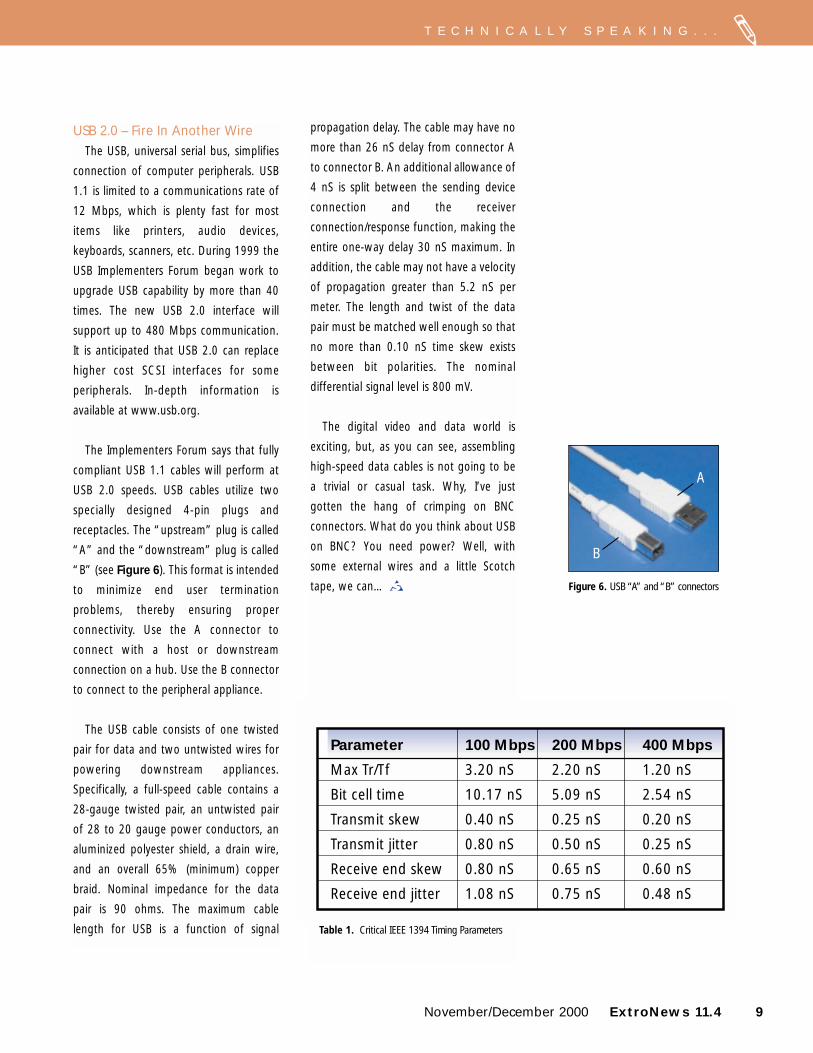
specification supports two plug
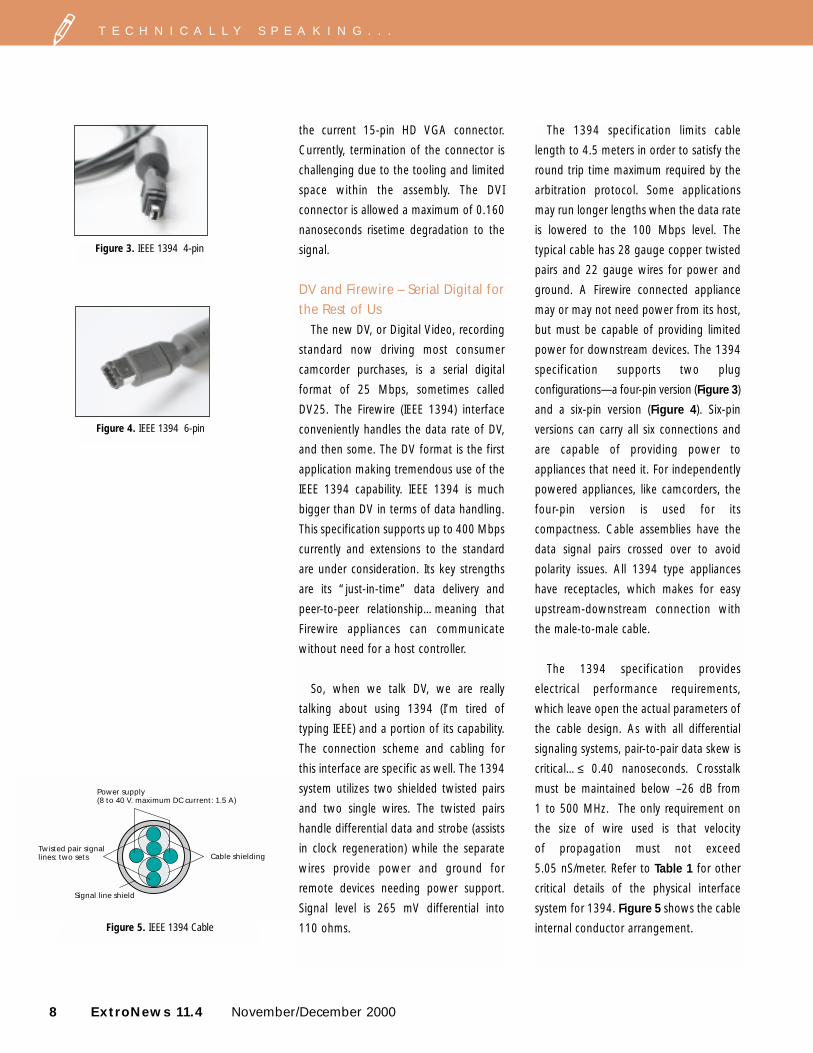
configurations—a four-pin version (Figure 3)
and a six-pin version (Figure 4). Six-pin
versions can carry all six connections and
are capable of providing power to
appliances that need it. For independently
powered appliances, like camcorders, the
four-pin version is used for its
compactness. Cable assemblies have the
data signal pairs crossed over to avoid
polarity issues. All 1394 type appliances
have receptacles, which makes for easy
upstream-downstream connection with
the male-to-male cable.
The 1394 specification provides
electrical performance requirements,
which leave open the actual parameters of
the cable design. As with all differential
signaling systems, pair-to-pair data skew is
critical…≤ 0.40 nanoseconds. Crosstalk
must be maintained below –26 dB from
1 to 500 MHz. The only requirement on
the size of wire used is that velocity
of propagation must not exceed
5.05 nS/meter. Refer to Table 1 for other
critical details of the physical interface
system for 1394. Figure 5 shows the cable
internal conductor arrangement.
T E C H N I C A L L Y S P E A K I N G . . .
Figure 3. IEEE 1394 4-pin
Figure 4. IEEE 1394 6-pin
propagation delay. The cable may have no
more than 26 nS delay from connector A
to connector B. An additional allowance of
4 nS is split between the sending device
connection and the receiver
connection/response function, making the
entire one-way delay 30 nS maximum. In
addition, the cable may not have a velocity
of propagation greater than 5.2 nS per
meter. The length and twist of the data
pair must be matched well enough so that
no more than 0.10 nS time skew exists
between bit polarities. The nominal
differential signal level is 800 mV.
The digital video and data world is
exciting, but, as you can see, assembling
high-speed data cables is not going to be
a trivial or casual task. Why, I’ve just
gotten the hang of crimping on BNC
connectors. What do you think about USB
on BNC? You need power? Well, with
some external wires and a little Scotch
tape, we can…
November/December 2000 ExtroNews 11.4 9
T E C H N I C A L L Y S P E A K I N G . . .
USB 2.0 – Fire In Another WireThe USB, universal serial bus, simplifies
connection of computer peripherals. USB
1.1 is limited to a communications rate of
12 Mbps, which is plenty fast for most
items like printers, audio devices,
keyboards, scanners, etc. During 1999 the
USB Implementers Forum began work to
upgrade USB capability by more than 40
times. The new USB 2.0 interface will
support up to 480 Mbps communication.
It is anticipated that USB 2.0 can replace
higher cost SCSI interfaces for some
peripherals. In-depth information is
available at www.usb.org.
The Implementers Forum says that fully
compliant USB 1.1 cables will perform at
USB 2.0 speeds. USB cables utilize two
specially designed 4-pin plugs and
receptacles. The “upstream” plug is called
“A” and the “downstream” plug is called
“B” (see Figure 6). This format is intended
to minimize end user termination
problems, thereby ensuring proper
connectivity. Use the A connector to
connect with a host or downstream
connection on a hub. Use the B connector
to connect to the peripheral appliance.
The USB cable consists of one twisted
pair for data and two untwisted wires for
powering downstream appliances.
Specifically, a full-speed cable contains a
28-gauge twisted pair, an untwisted pair
of 28 to 20 gauge power conductors, an
aluminized polyester shield, a drain wire,
and an overall 65% (minimum) copper
braid. Nominal impedance for the data
pair is 90 ohms. The maximum cable
length for USB is a function of signal
Parameter 100 Mbps 200 Mbps 400 Mbps
Max Tr/Tf 3.20 nS 2.20 nS 1.20 nS
Bit cell time 10.17 nS 5.09 nS 2.54 nS
Transmit skew 0.40 nS 0.25 nS 0.20 nS
Transmit jitter 0.80 nS 0.50 nS 0.25 nS
Receive end skew 0.80 nS 0.65 nS 0.60 nS
Receive end jitter 1.08 nS 0.75 nS 0.48 nS
Figure 6. USB “A” and “B” connectors
Table 1. Critical IEEE 1394 Timing Parameters
B
A
10 ExtroNews 11.4 November/December 2000
U N I Q U E T E C H N I Q U E S
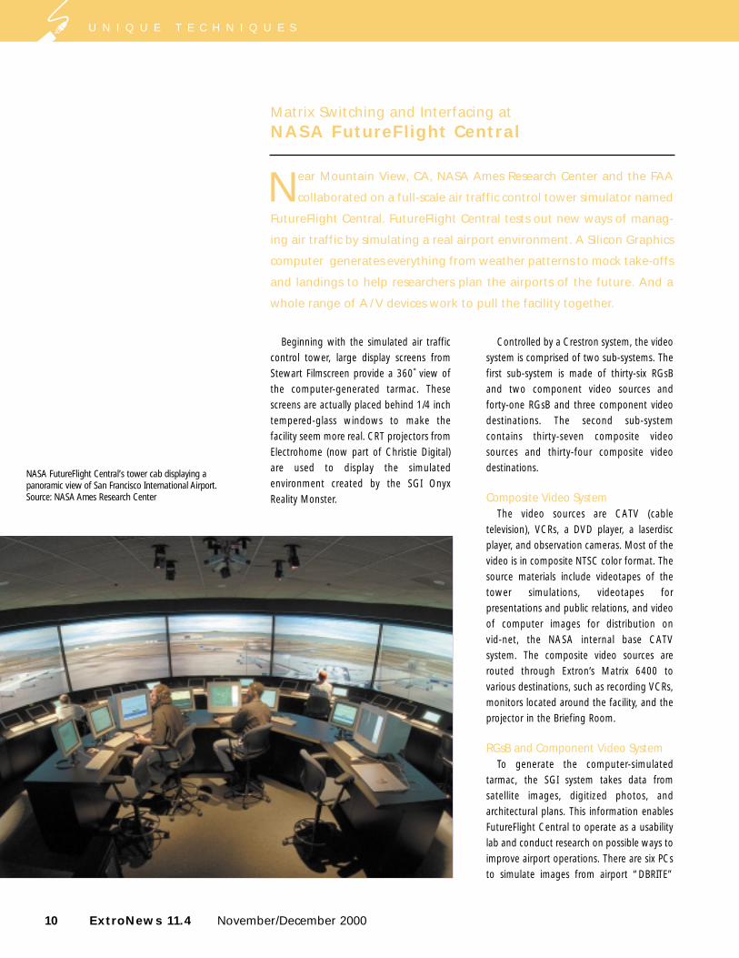
Beginning with the simulated air trafficcontrol tower, large display screens fromStewart Filmscreen provide a 360˚ view ofthe computer-generated tarmac. Thesescreens are actually placed behind 1/4 inchtempered-glass windows to make thefacility seem more real. CRT projectors fromElectrohome (now part of Christie Digital)are used to display the simulatedenvironment created by the SGI OnyxReality Monster.
Controlled by a Crestron system, the videosystem is comprised of two sub-systems. Thefirst sub-system is made of thirty-six RGsBand two component video sources and forty-one RGsB and three component videodestinations. The second sub-systemcontains thirty-seven composite videosources and thirty-four composite videodestinations.
Composite Video SystemThe video sources are CATV (cable
television), VCRs, a DVD player, a laserdiscplayer, and observation cameras. Most of thevideo is in composite NTSC color format. Thesource materials include videotapes of thetower simulations, videotapes forpresentations and public relations, and videoof computer images for distribution on vid-net, the NASA internal base CATVsystem. The composite video sources arerouted through Extron’s Matrix 6400 tovarious destinations, such as recording VCRs,monitors located around the facility, and theprojector in the Briefing Room.
RGsB and Component Video SystemTo generate the computer-simulated
tarmac, the SGI system takes data fromsatellite images, digitized photos, andarchitectural plans. This information enablesFutureFlight Central to operate as a usabilitylab and conduct research on possible ways toimprove airport operations. There are six PCsto simulate images from airport “DBRITE”
Matrix Switching and Interfacing atNASA FutureFlight Central
Near Mountain View, CA, NASA Ames Research Center and the FAA
collaborated on a full-scale air traffic control tower simulator named
FutureFlight Central. FutureFlight Central tests out new ways of manag-
ing air traffic by simulating a real airport environment. A Silicon Graphics
computer generates everything from weather patterns to mock take-offs
and landings to help researchers plan the airports of the future. And a
whole range of A / V devices work to pull the facility together.
NASA FutureFlight Central’s tower cab displaying apanoramic view of San Francisco International Airport.Source: NASA Ames Research Center
convert the RGsB format signal to RGBHVformat for the line doublers that do notaccept RGsB. Extron’s VTG 200 video testgenerator was installed to provide a testsignal for the RGsB/component videosystem and the composite video system.These test signals verified operation of thesystem and also were used for projectorsetup and matching.
FutureFlight Central was well-received atits opening. As for its A / V system—“Theylove it [the Matrix 6400]. It accommodatesall their current requirements, allows forfuture expansion, and we haven’t had anytrouble calls since we completed ourcontract,” noted Neuman.
For more information about FutureFlightCentral, please visit http://ffc.arc.nasa.gov
November/December 2000 ExtroNews 11.4 11
radar systems, which are displayed on sixhanging monitors in the tower cabin. Thereare also many wall and floor plates to plugany computer into the system to generateimages. All the computer-video and RGBsignals are in RGsB format. Component videois used for a limited number of runs betweenthe Betacam deck, preview monitor, scanconverter, and line doubler.
Matrix SwitchingThree 48 x 48 Matrix 6400 Basic Module
Enclosures (BMEs) are used for the red, green (with sync), and blue signals, as well ascomponent video (Y, R-Y, B-Y). The fourthMatrix 6400 BME routes composite video.The three RGsB/component video BMEsshare one control panel and operatetogether. The composite video BME has itsown control panel. Most switching is donedirectly via the Crestron control system.Virtual “rooms” were set up for the twelvetower outputs and the two sets of sixmonitors. Rooming is a feature that allowsspecific outputs (such as those in one room)to be grouped together so that they mayselect inputs independently of the rest of thematrix switcher. “This enabled us to set uppresets, for example, to make simultaneousswitches of all outputs to the towerprojectors for common configurations,”commented Eric Neuman, Intellisys Group’s(now part of MCSi) Director of TechnicalServices – Mountain View. Intellisys designedand installed the A / V system at FutureFlightCentral.
Neuman explained that the Matrix 6400was chosen because it offered the size neededwith the field-expandability required by thecontract—in a single chassis—in addition tothe high video bandwidth that was required.Two other important features were reliabilityand accessibility; Neuman recounted, “All theboards are accessible from the front panelwithout disconnecting the signal cables.”
Interfacing and Sync Processing Extron’s RGB 109 Plus computer-to-
video interfaces (now replaced by the RGB109xi) were chosen because they werededicated interfaces (perfect for thededicated computers—the DBRITES) andthey output RGsB signals. Neuman added,“Their LCD readouts are also useful forverifying valid input signals.” Extron’s RGB202xi universal interface (now replaced bythe RGB 202 Rxi) was chosen for itsflexibility in adapting to any computerinput source, including PCs, Macs, SGI,and Sun SPARC workstations. Additionalstrong points were the LCD readout, RGsBoutput, and available image positionadjustments.
Extron’s SC 110 sync processors andstabilizers (now replaced by the SC 210)
U N I Q U E T E C H N I Q U E S
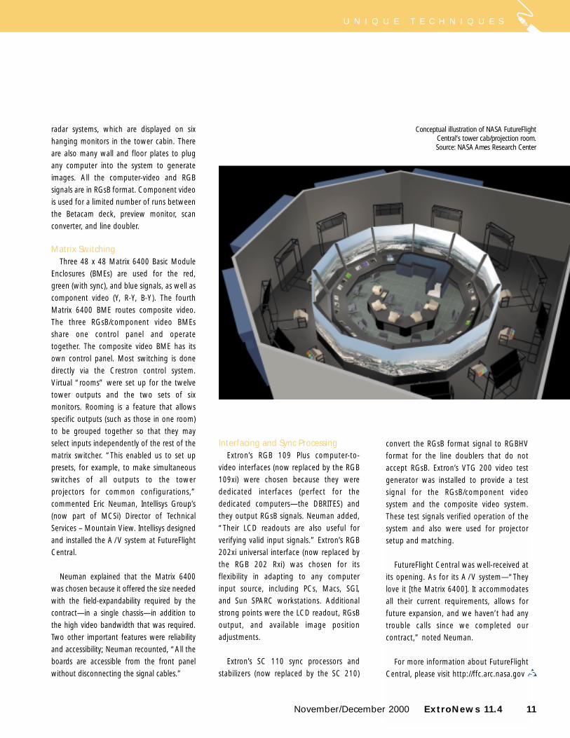
Conceptual illustration of NASA FutureFlightCentral’s tower cab/projection room.Source: NASA Ames Research Center
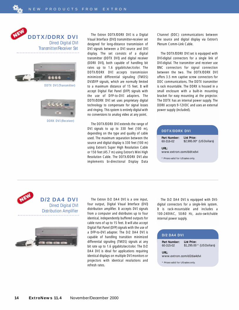
The Extron SVDA 6 A MX is a one input, sixbuffered output distribution amplifier. Itdistributes S-video (S-VHS) and stereo audiosignals. The SVDA 6 A MX offers theconvenience of a combination S-video andstereo audio DA in one half rack width, 1Uhigh, rack mountable enclosure.
For signal distribution in professional A / Vsystems and home theaters, the SVDA 6 A MXdistributes the NTSC, PAL, or SECAM signal ofany video source, such as a camera, VCR, orDVD player. The S-video output of a videosource can be split into six different,independently buffered outputs. The SVDA 6A MX also accepts and outputs balanced orunbalanced stereo audio signals for maximum
SVDA 6 A MXOne Input, Six Output,
S-video and Stereo AudioDistribution Amplifier
performance, flexibility, and ease of integrationinto the A / V system.
The SVDA 6 A MX provides 4-pin mini DINconnectors for S-video and 3.5 mm captivescrew connectors for stereo audio. It includes a100-240VAC, 50/60 Hz, auto-switchable,internal power supply.
SVDA 6 A MX
Part Number:60-353-01
URL:www.extron.com/svda6amx
* Prices valid for US sales only.
List Price:$625.00* (US Dollars)
12 ExtroNews 11.4 November/December 2000
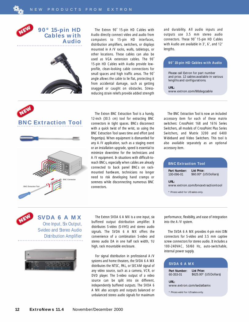
The Extron 90˚ 15-pin HD Cables withAudio directly connect video and audio fromcomputers to 15-pin HD interfaces,distribution amplifiers, switchers, or displaysmounted in A / V racks, walls, tabletops, orother locations. These cables can also beused as VGA extension cables. The 90˚ 15-pin HD Cables with Audio provide low-profile, clean-looking cable connections forsmall spaces and high traffic areas. The 90˚angle allows the cable to lie flat, protecting itfrom accidental damage, such as gettingsnagged or caught on obstacles. Stress-reducing strain reliefs provide added strength
90º 15-pin HDCables with
Audio
N E W P R O D U C T S F R O M E X T R O N
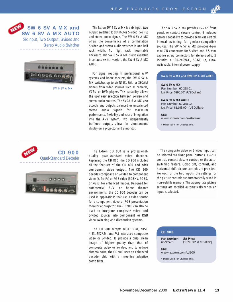
The Extron BNC Extraction Tool is a handy,12-inch (30.5 cm) tool for extracting BNCconnectors in tight spaces. BNCs disconnectwith a quick twist of the wrist, so using theBNC Extraction Tool saves time and effort (andfingertips). When equipment is dismantled forany A / V application, such as a staging eventor an installation upgrade, speed is essential tominimize downtime for the technicians andA / V equipment. In situations with difficult-to-reach BNCs, especially when cables are alreadyconnected to back panel BNCs on rack-mounted hardware, technicians no longerneed to risk developing hand cramps orsoreness while disconnecting numerous BNCconnectors.
BNC Extraction Tool
The BNC Extraction Tool is now an includedaccessory item for each of these matrixswitchers: CrossPoint 168 and 1616 SeriesSwitchers, all models of CrossPoint Plus SeriesSwitchers, and Matrix 3200 and 6400Wideband and Video Switchers. This tool isalso available separately as an optionalaccessory item.
90˚ 15-pin HD Cables with Audio
Please call Extron for part number and price. 12 cables available in variouslengths and configurations.
URL:www.extron.com/90degcable
BNC Extraction Tool
Part Number:100-096-01
URL:www.extron.com/bncextractiontool
* Prices valid for US sales only.
List Price:$60.00* (US Dollars)
and durability. All audio inputs andoutputs use 3.5 mm stereo audioconnectors. These 90˚ 15-pin HD Cableswith Audio are available in 3', 6', and 12'lengths.
BNC Extraction Tool
BNC Connector
The SW 6 SV A MX provides RS-232, frontpanel, or contact closure control. It includesgenlock capability to provide seamless verticalinterval switching for genlock-compatiblesources. The SW 6 SV A MX provides 4-pinmini-DIN connectors for S-video and 3.5 mmcaptive screw connectors for stereo audio. Itincludes a 100-240VAC, 50/60 Hz, auto-switchable, internal power supply.
November/December 2000 ExtroNews 11.4 13
N E W P R O D U C T S F R O M E X T R O N
The Extron CD 900 is a professional-quality quad-standard video decoder.Replacing the CD 800, the CD 900 includesall the features of the CD 800 and addscomponent video output. The CD 900decodes composite or S-video to componentvideo (Y, PB, PR) or RGB video (RGBHV, RGBS,or RGsB) for enhanced images. Designed forcommercial A / V or home theaterenvironments, the CD 900 decoder can beused in applications that use a video sourcefor a component video or RGB presentationmonitor or projector. The CD 900 can also beused to integrate composite video and S-video sources into component or RGBvideo switching and distribution systems.
The CD 900 accepts NTSC 3.58, NTSC4.43, SECAM, and PAL interlaced compositevideo or S-video. To provide a crisp, cleanimage of higher quality than that ofcomposite video or S-video, and to reducechroma noise, the CD 900 uses an enhanceddecoder chip with a three-line adaptive comb filter.
CD 900Quad-Standard Decoder
The composite video or S-video input canbe selected via front panel buttons, RS-232control, contact closure control, or the auto-switching feature. Color, tint, contrast, andhorizontal shift picture controls are provided.For each of the two inputs, the settings forthe picture controls are automatically saved innon-volatile memory. The appropriate picturesettings are recalled automatically when aninput is selected.
CD 900
Part Number:60-355-01
URL:www.extron.com/cd900
* Prices valid for US sales only.
List Price:$1,595.00* (US Dollars)
The Extron SW 6 SV A MX is a six input, twooutput switcher. It distributes S-video (S-VHS)and stereo audio signals. The SW 6 SV A MXoffers the convenience of a combination S-video and stereo audio switcher in one halfrack width, 1U high, rack mountableenclosure. The SW 6 SV A MX is also availablein an auto-switch version, the SW 6 SV A MXAUTO.
For signal routing in professional A / Vsystems and home theaters, the SW 6 SV AMX switches up to six NTSC, PAL, or SECAMsignals from video sources such as cameras,VCRs, or DVD players. This capability allowsthe user easy selection between S-video andstereo audio sources. The SVDA 6 A MX alsoaccepts and outputs balanced or unbalancedstereo audio signals for maximumperformance, flexibility, and ease of integrationinto the A / V system. Two independentlybuffered outputs allow for simultaneousdisplay on a projector and a monitor.
SW 6 SV A MX and SW 6 SV A MX AUTOSix Input, Two Output, S-video and
Stereo Audio Switcher
SW 6 SV A MX
SW 6 SV A MX and SW6 SV A MX AUTO
SW 6 SV A MXPart Number: 60-358-01List Price: $995.00* (US Dollars)
SW 6 SV A MX AUTOPart Number: 60-358-02 List Price: $1,195.00* (US Dollars)
URL:www.extron.com/sw6svamx
* Prices valid for US sales only.
14 ExtroNews 11.4 November/December 2000
The Extron DDTX/DDRX DVI is a DigitalVisual Interface (DVI) transmitter-receiver setdesigned for long-distance transmission ofDVI signals between a DVI source and DVIdisplay. The set consists of a digitaltransmitter (DDTX DVI) and digital receiver(DDRX DVI), both capable of handling bitrates up to 1.6 gigabits/sec/color. TheDDTX/DDRX DVI accepts transmissionminimized differential signaling (TMDS)DVI/DFP signals, which are normally limitedto a maximum distance of 15 feet. It willaccept Digital Flat Panel (DFP) signals withthe use of DFP-to-DVI adapters. TheDDTX/DDRX DVI set uses proprietary digitaltechnology to compensate for signal lossesand ringing. This system is entirely digital withno conversions to analog video at any point.
The DDTX/DDRX DVI extends the range ofDVI signals to up to 330 feet (100 m),depending on the type and quality of cableused. The maximum separation between thesource and digital display is 330 feet (100 m)using Extron’s Super High Resolution Cableor 150 feet (45.7 m) using Extron’s Mini HighResolution Cable. The DDTX/DDRX DVI alsoimplements bi-directional Display Data
DDTX/DDRX DVIDirect Digital DVI
Transmitter/Receiver Set
Channel (DDC) communications betweenthe source and digital display via Extron’sPlenum Comm-Link Cable.
The DDTX/DDRX DVI set is equipped withDVI-digital connectors for a single link ofDVI-digital. The transmitter and receiver useBNC connectors for signal connectionbetween the two. The DDTX/DDRX DVIoffers 3.5 mm captive screw connectors forDDC communications. The DDTX transmitteris rack mountable. The DDRX is housed in asmall enclosure with a built-in mountingbracket for easy mounting at the projector.The DDTX has an internal power supply. TheDDRX accepts 9-12VDC and uses an externalpower supply (included).
The Extron D/2 DA4 DVI is a one input,four output, Digital Visual Interface (DVI)distribution amplifier. It accepts DVI signalsfrom a computer and distributes up to fouridentical, independently buffered outputs forcable runs of up to 15 feet. It will also acceptDigital Flat Panel (DFP) signals with the use ofa DFP-to-DVI adapter. The D/2 DA4 DVI iscapable of handling transition minimizeddifferential signaling (TMDS) signals at anybit rate up to 1.6 gigabits/sec/color. The D/2DA4 DVI is ideal for applications requiringidentical displays on multiple DVI monitors orprojectors with identical resolutions andrefresh rates.
D/2 DA4 DVIDirect Digital DVI
Distribution Amplifier
The D/2 DA4 DVI is equipped with DVI-digital connectors for a single-link system. It is rack-mountable and includes a 100-240VAC, 50/60 Hz, auto-switchableinternal power supply.
N E W P R O D U C T S F R O M E X T R O N
DDTX/DDRX DVI
Part Number:60-316-02
URL:www.extron.com/ddtxdvi
* Prices valid for US sales only.
List Price:$2,995.00* (US Dollars)
D/2 DA4 DVI
Part Number:60-315-02
URL:www.extron.com/d2da4dvi
* Prices valid for US sales only.
List Price:$1,295.00 * (US Dollars)
DDRX DVI (Receiver)
DDTX DVI (Transmitter)
• Display PowerPoint slides and Excelspreadsheets with the computer setat 640 x 480 or as low a resolution aspossible—NTSC signals run atapproximately 720 x 480. By using acomputer resolution that’s close toNTSC to display the slides, lessinformation will have to be removedduring scan conversion—meaning thedisplayed image will more closely matchthe image on your computer screen.
• Use large fonts for any computer-based text (PowerPoint, Excel).
• Use sans-serif fonts, like Arial.
• Use a black border or line betweenadjacent colors to minimize chromacrawl.
Setting Up the Scan ConverterAdjusting the scan converter, as well, can
greatly improve the appearance of the scanconverted image. Most scan converters havemultiple adjustments designed to optimizethe output image for different image typesand scan rates. To get the best image, followthese steps in order:
1. Select the output standard (NTSCor PAL) that’s compatible with yourlocal system.
November/December 2000 ExtroNews 11.4 15
RS-232 Control
50/60 Hz 0.5A100-240
INPUT/LOOP OUTGENLOCK
VIDEO S-VIDEO R/R-Y G/Y B/B-Y H/HV V
OUTH
HV
SOG
DIGITALOUT
IN
VGAMAC
MENU FREEZE/RESET
GENLOCK
NEXTVSC 200
COMPUTER TO VIDEO SCAN CONVERTER
CENTERING/PAN
RS-232
REMOTE
PC Computer
INPUT OUTPUT CONTROL
S-video
Preview Monitor
Codec
VSC 200D
BUFFERED LOCAL
MONITOR OUTPUT
INPUT
H. SHIFT
RGB 103 xi
MAC INTERFACE W /ADSP
BUFFERED LOCAL
MONITOR OUTPUT
INPUT
H. SHIFT
RGB 103 xi
MAC INTERFACE W /ADSP
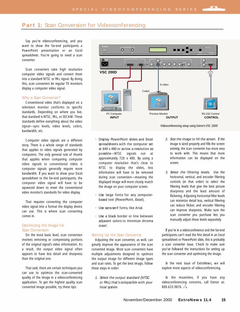
Say you’re videoconferencing, and youwant to show the far-end participants aPowerPoint presentation or an Excelspreadsheet. You’re going to need a scanconverter.
Scan converters take high resolutioncomputer video signals and convert theminto a standard NTSC or PAL signal. By doingthis, scan converters let regular TV monitorsdisplay a computer video signal.
Why a Scan Converter?Conventional video that’s displayed on a
television monitor conforms to specificstandards. Depending on where you live,that standard is NTSC, PAL, or SECAM. Thesestandards define everything about the videosignal—sync levels, video levels, colors,bandwidth, etc.
Computer video signals are a differentstory. There is a whole range of standardsthat applies to video signals generated bycomputers. The only general rule of thumbthat applies when comparing computervideo signals to conventional video iscomputer signals generally require morebandwidth. If you want to show your Excelspreadsheet to the far-end participants, thecomputer video signal will have to besqueezed down to meet the conventionalvideo monitor’s standards for video display.
That requires converting the computervideo signal into a format the display devicecan use. This is where scan converting comes in.
Optimizing the Image for Scan Conversion
On the most basic level, scan conversioninvolves removing or compressing portionsof the original signal’s video information. Asa result, the output video signal oftenappears to have less detail and sharpnessthan the original one.
That said, there are certain techniques youcan use to optimize the scan-convertedquality of the image in a videoconferencingapplication. To get the highest quality scanconverted image possible, try these tips:
Part 1: Scan Conversion for Videoconferencing
2. Size the image to fill the screen. If theimage is sized properly and fills the screenentirely, the scan converter has more areato work with. This means that moreinformation can be displayed on thescreen.
3. Select the filtering levels. Use thehorizontal, vertical, and encoder filteringcontrols (in that order) to select thefiltering levels that give the best picturesharpness and the least amount offlickering. Adjusting horizontal filter levelscan minimize detail loss, vertical filteringcan reduce flicker, and encoder filteringcan improve sharpness. Make sure thescan converter you purchase lets youmanually adjust these levels separately.
If you’re in a videoconference and the far-endparticipants can’t read the fine detail in an Excelspreadsheet or PowerPoint slide, this is probablya scan converter issue. Check to make sureyou’ve followed the instructions for setting upthe scan converter and optimizing the image.
In the next issue of ExtroNews, we willexplore more aspects of videoconferencing.
In the meantime, if you have anyvideoconferencing concerns, call Extron at:800.633.9876.
Videoconferencing setup using Extron’s VSC 200D
S P E C I A L V I D E O C O N F E R E N C I N G S E R I E S
16 ExtroNews 11.4 November/December 2000
This past summer, at the US FederalCourthouse in Foley Square, Manhattan,New York, a bench trial (no jury) was heldbetween the US Government and threemajor credit card companies. The temporaryA / V system used during this three-month-long antitrust court case was provided byVisual Word Systems of New York.
SourcesThe four sets of attorneys representing the
four parties involved in the case utilizedExtron interfaces to connect a total of sixcomputers to the A / V system. Takingadvantage of the Extron RGB 202xi two-input, universal computer-video interface(now replaced by the Extron RGB 202 Rxi),the attorneys used its switching capability byconnecting only one laptop to each interfaceand leaving the second input unused. Whenthey switched the RGB 202xi toggle switchto display the unused input, the output tothe courtroom displays was blanked sincethere were no images from a second sourceto display. The attorneys were then able topreview images off-line on their laptopsbefore flipping the toggle switch back to
R E N T A L & S T A G I N G C O R N E R
display their images. The unused inputs alsoserved as backup for connecting additionalcomputers as needed throughout the trial.
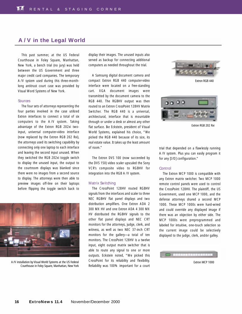
A Samsung digital document camera andcompact Extron RGB 440 computer-videointerface were located on a free-standingcart. XGA document images weretransmitted by the document camera to theRGB 440. The RGBHV output was thenrouted to an Extron CrossPoint 128HV MatrixSwitcher. The RGB 440 is a universal,architectural, interface that is mountablethrough or under a desk or almost any otherflat surface. Ike Eckstein, president of VisualWorld Systems, explained his choice, “Wepicked the RGB 440 because of its size, itsreal estate value. It takes up the least amountof room.”
The Extron DVS 100 (now succeeded bythe DVS 150) video scaler upscaled the SonyVCR’s composite video to RGBHV forintegration into the RGB A / V system.
Matrix SwitchingThe CrossPoint 128HV routed RGBHV
signals from the interfaces and scaler to threeNEC RGBHV flat panel displays and twodistribution amplifiers. One Extron ADA 2300 MX HV and one Extron ADA 4 300 MXHV distributed the RGBHV signals to theother flat panel displays and NEC CRTmonitors for the attorneys, judge, clerk, andwitness, as well as two NEC 37-inch CRTmonitors for the gallery—a total of tenmonitors. The CrossPoint 128HV is a twelveinput, eight output matrix switcher that isable to route any signal to one or moreoutputs. Eckstein noted, “We picked thisCrossPoint for its reliability and flexibility.Reliability was 100% important for a court
trial that depended on a flawlessly runningA / V system. Plus you can easily program itfor any [I /O] configuration.”
ControlThe Extron MCP 1000 is compatible with
any Extron matrix switcher. Two MCP 1000remote control panels were used to controlthe CrossPoint 128HV. The plaintiff, the USGovernment, used one MCP 1000, and thedefense attorneys shared a second MCP1000. These MCP 1000s were hard-wiredand could override any displayed image ifthere was an objection by either side. TheMCP 1000s were preprogrammed andlabeled for intuitive, one-touch selection sothe current image could be selectivelydisplayed to the judge, clerk, and/or galley.
A/V in the Legal World
Extron RGB 440
A/V installation by Visual World Systems at the US FederalCourthouse in Foley Square, Manhattan, New York
Extron RGB 202 Rxi
Extron MCP 1000
Witness Monitoring SystemDue to the layout of the courtroom, some
attorneys were not able to see the witnesseswithout the aid of a CCTV (closed circuittelevision) monitoring system. A Panasonicvideo camera and an Extron CVDA 6 MXdistribution amplifier were added to the A / Vcart that held the document camera and itsExtron interface. With one input and sixoutputs available, the CVDA 6 MXdistributed the camera’s composite videosignal to five Panasonic monitors located atthe attorneys’ and the court clerk’s tables.
CablesThe courtroom A / V system used different
types of Extron cable: BNC-5 Mini HR Cable,15-pin HD Cable, RS-232 Cable, and Comm-Link Cable. The BNC-5 Mini HR Cable passed
November/December 2000 ExtroNews 11.4 17
R E N T A L & S T A G I N G C O R N E R
Extron BNC-5 Mini HR Cable
Extron RS-232 Cable
Extron Comm-Link Cable
New Name, Improved Interface... “E-Demos” are Online!
You told us how valuable the Extron “Webcasts” are—how effectively the high quality sound,graphics, and computer animation work together to demonstrate each product. You also told us thatthe name “Webcast” doesn’t do justice to the usefulness and content these tools deliver. We listenedto your feedback and created a new name that better describes these multimedia presentations—Extron E-Demos. E-Demos can be easily accessed through the Extron Web site at www.extron.com.Now you can learn all about new products without leaving the comfort of your favorite Internetbrowser.
These demos are excellent learning tools for sales personnel, installers, service professionals, and endusers. Just point and click to control the demo for an instant presentation.
Currently, the following E-Demos are available:Product Demo Posted• P/2 DA1 June 19, 2000• RGB 202 Rxi June 19, 2000• Introduction to Extron’s Webcasts June 20, 2000• Extron’s Dealer-Only Site July 11, 2000• SGS 408 July 11, 2000• YCS Transcoder November 7, 2000• System 7SC November 29, 2000
As another plus, we’ve improved the interface to enhance these E-Demos. During any section of the demo, you can use the on-screen videocontrol panel to play, stop, rewind, or fast-forward the movie—like an online VCR—and you can even zoom in at any time. Now you can quicklyfast-forward to the spot you want to see again, or rewind if you want to review certain segments in detail.
We are always posting new E- Demos to our site. Check us out regularly. Go online at www.extron.com and click on the E-Demo logo.
the RGBHV signals. The document camera’soutput was routed to the RGB 440 on 15-pinHD Cable. RS-232 Cable carried the serialcommunications between the MCP 1000sand the CrossPoint 128HV. Between theMCP 1000s, control communications weretransmitted over Comm-Link Cable.
Eckstein commented on the reliability ofthis elaborate courtroom A / V system. “Wehave not needed to swap out a single pieceof equipment during the entire, almost threemonth-long trial... Technically it’s one of thesmoothest setups we’ve ever done.”
For more information, please contactVisual Word Systems at 212.629.8383 [email protected].
Extron 15-pin HDStaging Cable
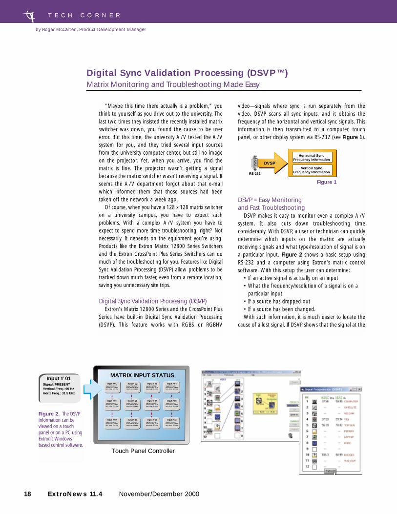
video—signals where sync is run separately from thevideo. DSVP scans all sync inputs, and it obtains thefrequency of the horizontal and vertical sync signals. Thisinformation is then transmitted to a computer, touchpanel, or other display system via RS-232 (see Figure 1).
DSVP = Easy Monitoring and Fast Troubleshooting
DSVP makes it easy to monitor even a complex A / Vsystem. It also cuts down troubleshooting timeconsiderably. With DSVP, a user or technician can quicklydetermine which inputs on the matrix are actuallyreceiving signals and what type/resolution of signal is ona particular input. Figure 2 shows a basic setup using RS-232 and a computer using Extron's matrix controlsoftware. With this setup the user can determine:
• If an active signal is actually on an input• What the frequency/resolution of a signal is on a
particular input • If a source has dropped out• If a source has been changed.With such information, it is much easier to locate the
cause of a lost signal. If DSVP shows that the signal at the
Touch Panel Controller
Input # 01Signal: PRESENTVertical Freq.: 60 Hz Horiz Freq.: 31.5 kHz
MATRIX INPUT STATUSInput # 01
Signal: PRESENTVertical Freq.: 60 Hz Horz Freq.: 31.5 kHz
Input # 02Signal: PRESENTVertical Freq.: 60 Hz Horz Freq.: 31.5 kHz
Input # 03Signal: PRESENTVertical Freq.: 60 Hz Horz Freq.: 31.5 kHz
Input # 04Signal: PRESENTVertical Freq.: 60 Hz Horz Freq.: 31.5 kHz
Input # 05Signal: PRESENTVertical Freq.: 60 Hz Horz Freq.: 31.5 kHz
Input # 06Signal: PRESENTVertical Freq.: 60 Hz Horz Freq.: 31.5 kHz
Input # 07Signal: PRESENTVertical Freq.: 60 Hz Horz Freq.: 31.5 kHz
Input # 08Signal: PRESENTVertical Freq.: 60 Hz Horz Freq.: 31.5 kHz
Input # 09Signal: PRESENTVertical Freq.: 60 Hz Horz Freq.: 31.5 kHz
Input # 10Signal: PRESENTVertical Freq.: 60 Hz Horz Freq.: 31.5 kHz
Input # 11Signal: PRESENTVertical Freq.: 60 Hz Horz Freq.: 31.5 kHz
Input # 12Signal: PRESENTVertical Freq.: 60 Hz Horz Freq.: 31.5 kHz
18 ExtroNews 11.4 November/December 2000
T E C H C O R N E R
“Maybe this time there actually is a problem,” youthink to yourself as you drive out to the university. Thelast two times they insisted the recently installed matrixswitcher was down, you found the cause to be usererror. But this time, the university A / V tested the A / Vsystem for you, and they tried several input sourcesfrom the university computer center, but still no imageon the projector. Yet, when you arrive, you find thematrix is fine. The projector wasn’t getting a signalbecause the matrix switcher wasn’t receiving a signal. Itseems the A / V department forgot about that e-mailwhich informed them that those sources had beentaken off the network a week ago.
Of course, when you have a 128 x 128 matrix switcheron a university campus, you have to expect suchproblems. With a complex A / V system you have toexpect to spend more time troubleshooting, right? Notnecessarily. It depends on the equipment you’re using.Products like the Extron Matrix 12800 Series Switchersand the Extron CrossPoint Plus Series Switchers can domuch of the troubleshooting for you. Features like DigitalSync Validation Processing (DSVP) allow problems to betracked down much faster, even from a remote location,saving you unnecessary site trips.
Digital Sync Validation Processing (DSVP) Extron's Matrix 12800 Series and the CrossPoint Plus
Series have built-in Digital Sync Validation Processing(DSVP). This feature works with RGBS or RGBHV
Digital Sync Validation Processing (DSVP™)Matrix Monitoring and Troubleshooting Made Easy
by Roger McCarten, Product Development Manager
Figure 2. The DSVPinformation can beviewed on a touchpanel or on a PC usingExtron’s Windows-based control software.
DVSP
Horizontal SyncFrequency Information
Vertical SyncFrequency InformationRS-232
Figure 1
November/December 2000 ExtroNews 11.4 19
RS-232
RS-232
RS-232
RS-232
RS-232
RS-232
INPUT 1 HORIZONTAL = 31.5 kHZ VERTICAL = 60 HZINPUT 2 HORIZONTAL = 57.0 kHZ VERTICAL = 70 HZ
INPUT 1 HORIZONTAL = 31.5 kHZ VERTICAL = 60 HZINPUT 2 HORIZONTAL = 57.0 kHZ VERTICAL = 70 HZ
Touch Panel
Computer 1
RGB 202 Rxi
DVS 150
RGB 202 Rxi
Projector 1
Projector 2
Computer 2
Projector 1INPUT 1DVS 150Signal: PRESENTSync Type: H&VVertical Freq.: 60 HzHorz Freq.: 31.5 kHz
Signal: PRESENTVertical Freq.: 60 HzHorz Freq.: 31.5 kHz
Signal: PRESENTSync Type: H&VVertical Freq.: 60 HzHorz Freq.: 31.5 kHz
CrossPoint Plus Series Switcher
I/OCONTROL
CROSSPOINT Plus MATRIX SERIES SWITCHER with DSVPTM
SYSTEM STATUS
DVD Player
RATEV SHIFTH SHIFTCONTRASTBRITTINTCOLOR
1
2
3
4DVS 150
DIGITAL VIDEO SCALER
ADJUST
INPUT
DVS 150Signal: PRESENTSync Type: H&VVertical Freq.: 60 Hz Horz Freq.: 31.5 kHz
Input # 01Signal: PRESENTVertical Freq.: 60 Hz Horz Freq.: 31.5 kHz
Projector 01Signal: PRESENTSync Type: H&VVertical Freq.: 60 Hz Horz Freq.: 31.5 kHz
RGB 202 RxiSignal: PRESENTSync Type: H&VVertical Freq.: 60 Hz Horz Freq.: 31.5 kHz
Input # 02Signal: PRESENTVertical Freq.: 60 Hz Horz Freq.: 31.5 kHz
Projector 02Signal: PRESENTSync Type: H&VVertical Freq.: 60 Hz Horz Freq.: 31.5 kHz
RGB 202 RxiSignal: PRESENTSync Type: H&VVertical Freq.: 60 Hz Horz Freq.: 31.5 kHz
Input # 03Signal: PRESENTVertical Freq.: 60 Hz Horz Freq.: 31.5 kHz
Projector 03Signal: PRESENTSync Type: H&VVertical Freq.: 60 Hz Horz Freq.: 31.5 kHz
November/December 2000 ExtroNews 11.4 19
source has dropped out, then the user knowsthe source side is the problem. If there is nosignal at the projector and DSVP shows thereis an active source on the input, then theuser/technician knows the problem lies afterthe input of the matrix.
Consider the value of knowing the lastitem on the above list—knowing that adifferent source is on an input than wasexpected. In big matrix systems, signalchanges are often made without all the usersbeing notified. Being able to find thisinformation out via DSVP can saveconsiderable time during troubleshooting.
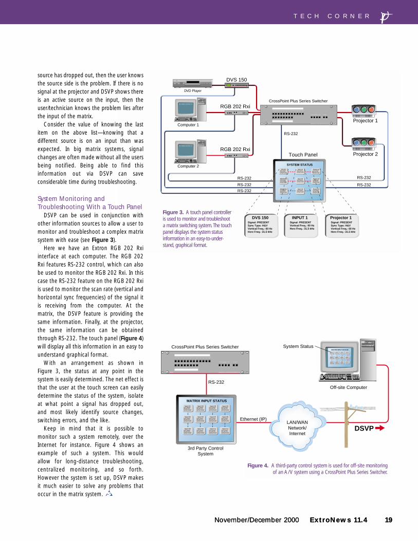
System Monitoring andTroubleshooting With a Touch Panel
DSVP can be used in conjunction withother information sources to allow a user tomonitor and troubleshoot a complex matrixsystem with ease (see Figure 3).
Here we have an Extron RGB 202 Rxiinterface at each computer. The RGB 202Rxi features RS-232 control, which can alsobe used to monitor the RGB 202 Rxi. In thiscase the RS-232 feature on the RGB 202 Rxiis used to monitor the scan rate (vertical andhorizontal sync frequencies) of the signal itis receiving from the computer. At thematrix, the DSVP feature is providing thesame information. Finally, at the projector,the same information can be obtainedthrough RS-232. The touch panel (Figure 4)will display all this information in an easy tounderstand graphical format.
With an arrangement as shown in Figure 3, the status at any point in thesystem is easily determined. The net effect isthat the user at the touch screen can easilydetermine the status of the system, isolateat what point a signal has dropped out, and most likely identify source changes,switching errors, and the like.
Keep in mind that it is possible tomonitor such a system remotely, over theInternet for instance. Figure 4 shows anexample of such a system. This would allow for long-distance troubleshooting,centralized monitoring, and so forth.However the system is set up, DSVP makesit much easier to solve any problems thatoccur in the matrix system.
CrossPoint Plus Series Switcher
Off-site Computer
3rd Party ControlSystem
Ethernet (IP)
System Status
I/OCONTROL
CROSSPOINT Plus MATRIX SERIES SWITCHER with DSVPTM
MATRIX INPUT STATUSInput # 01
Signal: PRESENTSync Type: H&VVertical Freq.: 60 Hz Horz Freq.: 31.5 kHz
Input # 02Signal: PRESENTSync Type: H&VVertical Freq.: 60 Hz Horz Freq.: 31.5 kHz
Input # 03Signal: PRESENTSync Type: H&VVertical Freq.: 60 Hz Horz Freq.: 31.5 kHz
MATRIX INPUT STATUS
Input # 9Signal: PRESENTSync Type: H&VVertical Freq.: 31.5 kHzHorizontal Freq.: 60 Hz
Input # 10Signal: PRESENTSync Type: H&VVertical Freq.: 31.5 kHzHorizontal Freq.: 60 Hz
Input # 11Signal: PRESENTSync Type: H&VVertical Freq.: 31.5 kHzHorizontal Freq.: 60 Hz
Input # 05Signal: PRESENTSync Type: H&VVertical Freq.: 31.5 kHzHorizontal Freq.: 60 Hz
Input # 06Signal: PRESENTSync Type: H&VVertical Freq.: 31.5 kHzHorizontal Freq.: 60 Hz
Input # 07Signal: PRESENTSync Type: H&VVertical Freq.: 31.5 kHzHorizontal Freq.: 60 Hz
Input # 08Signal: PRESENTSync Type: H&VVertical Freq.: 31.5 kHzHorizontal Freq.: 60 Hz
Input # 01Signal: PRESENTSync Type: H&VVertical Freq.: 31.5 kHzHorizontal Freq.: 60 Hz
Input # 02Signal: PRESENTSync Type: H&VVertical Freq.: 31.5 kHzHorizontal Freq.: 60 Hz
Input # 03Signal: PRESENTSync Type: H&VVertical Freq.: 31.5 kHzHorizontal Freq.: 60 Hz
Input # 04Signal: PRESENTSync Type: H&VVertical Freq.: 31.5 kHzHorizontal Freq.: 60 Hz
Input # 12Signal: PRESENTSync Type: H&VVertical Freq.: 31.5 kHzHorizontal Freq.: 60 Hz
DSVP
RS-232
Input # 04Signal: PRESENTSync Type: H&VVertical Freq.: 60 Hz Horz Freq.: 31.5 kHz
Input # 05Signal: PRESENTSync Type: H&VVertical Freq.: 60 Hz Horz Freq.: 31.5 kHz
Input # 06Signal: PRESENTSync Type: H&VVertical Freq.: 60 Hz Horz Freq.: 31.5 kHz
Input # 07Signal: PRESENTSync Type: H&VVertical Freq.: 60 Hz Horz Freq.: 31.5 kHz
Input # 08Signal: PRESENTSync Type: H&VVertical Freq.: 60 Hz Horz Freq.: 31.5 kHz
Input # 09Signal: PRESENTSync Type: H&VVertical Freq.: 60 Hz Horz Freq.: 31.5 kHz
Input # 10Signal: PRESENTSync Type: H&VVertical Freq.: 60 Hz Horz Freq.: 31.5 kHz
Input # 11Signal: PRESENTSync Type: H&VVertical Freq.: 60 Hz Horz Freq.: 31.5 kHz
Input # 12Signal: PRESENTSync Type: H&VVertical Freq.: 60 Hz Horz Freq.: 31.5 kHz
LAN/WANNetwork/Internet
T E C H C O R N E R
Figure 4. A third-party control system is used for off-site monitoringof an A/V system using a CrossPoint Plus Series Switcher.
Figure 3. A touch panel controlleris used to monitor and troubleshoota matrix switching system. The touchpanel displays the system statusinformation in an easy-to-under-stand, graphical format.
20 ExtroNews 11.4 November/December 2000
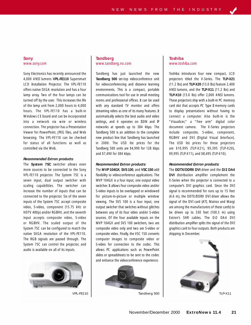
Mitsubishiwww.mitsubishi-presentations.com
Mitsubishi’s Presentation Products Divisionrecently introduced their flagship XGA LCDprojector, the X400. It offers 3,000 ANSIlumens and weighs in at 14 pounds. TheX400 portable desktop LCD projectorproduces a native XGA resolution with amaximum SXGA resolution. It is compatiblewith composite video, S-video, component,RGBHV, and DVI (Digital Visual Interface).The X400 has a presentation feature thatallows two simultaneous inputs to beviewed, allowing for a picture-in-pictureeffect. List price is $12,995 (USD).
Recommended Extron products: For DVI applications, the DDTX/DDRX DVIdriver and the D/2 DA4 DVI distributionamplifier complement the X400 when theprojector is connected to a computer’s DVIgraphics card. Since the DVI signal isrecommended for runs up to 15 feet (4.6 m),the DDTX/DDRX DVI driver allows the signalof the DVI card (ATI, Matrox and Margi areamong the manufacturers of these cards) tobe driven up to 330 feet (100.5 m) usingExtron’s SHR cables. The D/2 DA4 DVIdistribution amplifier splits the signal of theDVI graphics card to four outputs. Bothproducts are shipping in December.
ExtroNews publishes information about new products that are relative to the Extron product line in the New News section. Also listed arethe recommended Extron products that will complement these new display devices in their targeted applications. If you would like a newproduct to be reviewed for New News, please send a press release, literature, contact name, and a four-color slide or photo to: New News c/o Ginger Dodier, Extron Electronics, 1230 South Lewis Street, Anaheim, CA 92805, phone: (714) 491-1500, ext. 6270or e-mail to [email protected]
X400
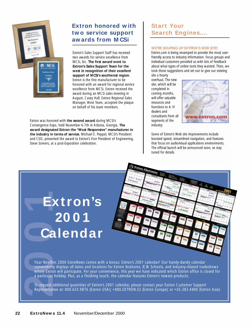
NECwww.nectech.com
NEC Technologies, Inc., ships the newgeneration of MT50 series, which iscomprised of three full-featured portableprojectors for use in conference rooms andclassrooms. The LCD-based MultiSyncMT1050 and MT1055 projectors offer XGAnative resolution and 2,100 and 2,600 ANSIlumens of brightness respectively, and theMT850 supplies SVGA resolution and 1,700ANSI lumens of brightness. All three projectorsare HDTV compatible, have monitor and audioout connectors, and offer a built-inPresentation Viewer, which enables users todownload presentations directly from theirlaptops. USD list prices for the projectors are$7,395 for the MT850, $9,995 for theMT1050 and $12,995 for the MT1055.
Recommended Extron products: The SW VGA Switchers and P/2 DAdistribution amplifiers are additions that canmultiply the projector’s inputs or PC’soutputs. The SW VGA series are 2, 4, or 6input switchers with 15-pin HD connectors.The switchers add to the MT series’ two 15-pin HD connectors, allowing multiple PCsto be switched to one projector. The P/2 DA2, 4, or 6 distribution amplifiers drive the PCsignal as well as distribute one PC’s signal tomultiple MT50 series projectors. Connectingall these components together are theExtron 15-pin HD cable assemblies. Thesecables are offered in plenum and non-plenum jackets and are genderselectable on the ends.
MT1055PowerLite 8100i
N E W N E W S F R O M T H E I N D U S T R Y
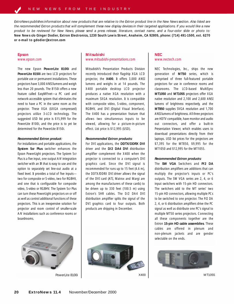
Epsonwww.epson.com
The new Epson PowerLite 8100i andPowerLite 8150i are two LCD projectors forportable use or permanent installations. Theseprojectors have 3,000 ANSI lumens and weighless than 20 pounds. The 8150i offers a newfeature called EasyMP.net—a PC card andnetwork-accessible system that eliminates theneed to have a PC in the same room as theprojector. These XGA (UXGA compressed)projectors utilize 3-LCD technology. Thesuggested USD list price is $15,999 for thePowerLite 8100i, and the price is to yet bedetermined for the PowerLite 8150i.
Recommended Extron product: For installations and portable applications, theSystem 5cr Plus switcher enhances theEpson PowerLight projectors. The System 5crPlus is a five input, one output A/V integrationswitcher with an IR that is easy to use and theoption to separately set line-out audio at afixed level. It provides a total of five inputs—two for composite or S-video, two for RGBHV,and one that is configurable for compositevideo, S-video or RGBHV. The System 5cr Pluscan turn these PowerLight projectors on or offas well as control additional functions of theseprojectors. This is an inexpensive solution forprojector and room control of smaller-scaleA/V installations such as conference rooms orboardrooms.
November/December 2000 ExtroNews 11.4 21
Sonywww.sony.com
Sony Electronics has recently announced the4,000 ANSI lumens VPL-FE110 SupersmartLCD Installation Projector. The VPL-FE110offers native SXGA resolution and has a fourlamp array. Two of the four lamps can beturned off by the user. This increases the lifeof the lamp unit from 2,000 hours to 4,000hours. The VPL-FE110 has a built-inWindows CE board and can be incorporatedinto a network via wire or wirelessconnection. The projector has a PresentationViewer for PowerPoint, JPEG files, and Webbrowsing. The VPL-FE110 can be checkedfor status of all functions as well ascontrolled via the Web.
Recommended Extron products: The System 7SC switcher allows even more sources to be connected to the SonyVPL-FE110 projector. The System 7SC is aseven input, dual output switcher withscaling capabilities. The switcher canincrease the number of inputs that can beconnected to the projector. Six of the seveninputs of the System 7SC accept compositevideo, S-video, component (15.75 kHz orHDTV 480p) and/or RGBHV, and the seventhinput accepts composite video, S-video or RGBHV. The scaled output of the System 7SC can be configured to match thenative SXGA resolution of the VPL-FE110.The RGB signals are passed through. TheSystem 7SC can control the projector, andaudio is available on all of its inputs.
VPL-FE110
Tandbergwww.tandberg.no.com
Tandberg has just launched the newTandberg 500 set-top videoconference unitfor videoconferencing and distance learningenvironments. This is a compact, portablecommunications tool for use in small meetingrooms and professional offices. It can be usedwith any standard TV monitor and offersstreaming video as one of its many features. Itautomatically selects the best audio and videosettings, and it operates on ISDN and IPnetworks at speeds up to 384 kbps. TheTandberg 500 is an addition to the completenew product line that Tandberg has launchedin 2000. The USD list prices for the Tandberg 500 units are $4,990 for 128 kbpsand $7,490 for 384 kbps.
Recommended Extron products: The MVP 104GX, SVS 100, and VSC 150 addflexibility to videoconference applications. TheMVP 104GX is a four input, one output videoswitcher. It allows four composite video and/orS-video inputs to be overlapped or windowedfor picture-in-picture or multiple windowviewing. The SVS 100 is a four input, oneoutput switcher that switches without glitchesbetween any of its four video and/or S-videosources. Of the four available inputs on theMVP 104GX and SVS 100 switchers, two arecomposite video only and two are S-video orcomposite video. Finally, the VSC 150 convertscomputer images to composite video or S-video for connection to the codec. Thisallows PC applications such as PowerPointslides or spreadsheets to be sent to the codecand enhance the videoconference experience.
Tandberg 500
Toshibawww.toshiba.com
Toshiba introduces four new compact, LCDprojectors titled the X-Series. The TLP-X21(11.2 lbs) and TLP-X20 (13.0 lbs) feature 2,400ANSI lumens, and the TLP-X11 (11.2 lbs) andTLP-X10 (13.0 lbs) offer 2,000 ANSI lumens.These projectors ship with a built-in PC memorycard slot that accepts PC Type II memory cardsto display presentations without having toconnect a computer. Also built-in is the“Visualizer,” a “free arm” digital colordocument camera. The X-Series projectorsinclude composite, S-video, component,RGBHV and DVI (Digital Visual Interface). The USD list prices for these projectors are $10,995 (TLP-X21), $9,395 (TLP-X20), $9,995 (TLP-X11), and $8,495 (TLP-X10).
Recommended Extron products: The DDTX/DDRX DVI driver and the D/2 DA4DVI distribution amplifier complement the X-Series when the projector is connected to acomputer’s DVI graphics card. Since the DVIsignal is recommended for runs up to 15 feet(4.6 m), the DDTX/DDRX DVI driver allows thesignal of the DVI card (ATI, Matrox and Margiare among the manufacturers of these cards) tobe driven up to 330 feet (100.5 m) usingExtron’s SHR cables. The D/2 DA4 DVIdistribution amplifier splits the signal of the DVIgraphics card to four outputs. Both products areshipping in December.
TLP-X11
N E W N E W S F R O M T H E I N D U S T R Y
22 ExtroNews 11.4 November/December 2000
2001
Start Your Search Engines….
WE’RE SOUPING UP EXTRON’S WEB SITE!Extron.com is being revamped to provide the most user-friendly access to industry information. Focus groups andindividual customers provided us with lots of feedbackabout what types of online tools they wanted. Then, wetook those suggestions and set out to give our existingsite a heartyoverhaul. The newsite, which will becompleted incoming months,will offer valuableresources andfunctions to A / Vdealers andconsultants from allsegments of theindustry.
Some of Extron’s Web site improvements includeboosted speed, streamlined navigation, and featuresthat focus on audio/visual applications environments.The official launch will be announced soon, so staytuned for details.
Extron honored withtwo service supportawards from MCSi
Extron’s Sales Support Staff has receivedtwo awards for service excellence fromMCSi, Inc. The first award went toExtron’s Sales Support Team for thewest in recognition of their excellentsupport of MCSi’s southwest region.Extron is the first manufacturer to behonored with an award for regional serviceexcellence from MCSi. Extron received theaward during an MCSi sales meeting inAugust. Casey Hall, Extron Regional SalesManager, West Team, accepted the plaqueon behalf of his team members.
Extron was honored with the second award during MCSi’sConvergence Expo, held November 6-7th in Atlanta, Georgia. Theaward designated Extron the “Most Responsive” manufacturer inthe industry in terms of service. Michael E. Peppel, MCSi’s Presidentand CEO, presented the award to Extron’s Vice President of Engineering,Steve Somers, at a post-Exposition celebration.
Your Nov/Dec 2000 ExtroNews comes with a bonus: Extron’s 2001 calendar! Our handy-dandy calendarconveniently displays all dates and locations for Extron Institutes, ICIA Schools, and industry-related tradeshowswhere Extron will participate. For your convenience, this year we have indicated which Extron office is closed fora particular holiday. Plus, as a finishing touch, the calendar features Extron’s newest products.
To request additional quantities of Extron’s 2001 calendar, please contact your Extron Customer SupportRepresentative at: 800.633.9876 (Extron USA); +800.EXTRON.S3 (Extron Europe); or +65.383.4400 (Extron Asia).
Extron’s2001
Calendar
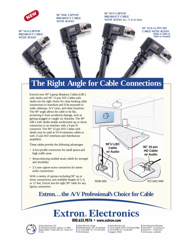
Extron Electronics, USA1230 South Lewis Street, Anaheim, CA 92805800.633.9876 714.491.1500 FAX 714.491.1517USA
Extron Electronics, EuropeBeeldschermweg 6C, 3821 AH Amersfoort+31.33.453.4040 FAX +31.33.453.4050The Netherlands
Extron Electronics, Asia135 Joo Seng Rd. #04-01, PM Industrial Bldg.+65.383.4400 FAX +65.383.4664Singapore 368363
Extron Electronics InformationExtronWEB™: www.extron.comExtronFAX™: 714.491.019224-hour access—worldwide!
800.633.9876 • www.extron.com
Extron. . . the A/V Professional’s Choice for Cable
The Right Angle for Cable ConnectionsExtron’s new 90° Laptop Breakout Cables (LBC)with Audio and 90° 15-pin HD Cables withAudio are the right choice for clean-looking cableconnections to interfaces and DAs mounted inwalls, tabletops, A/V racks, and other locations.The 90° angle allows the cable to lie flat,protecting it from accidental damage, such asgetting snagged or caught on obstacles. The 90°LBCs with Audio enable unobtrusive up or downconnection to an interface with a 9-pin Dconnector. The 90° 15-pin HD Cables withAudio may be used as VGA extension cables orwith 15-pin HD interfaces and distributionamplifiers.
These cables provide the following advantages:
• A low-profile connection for small spaces andhigh traffic areas
• Stress-reducing molded strain reliefs for strengthand durability
• 3.5 mm captive screw connectors for stereoaudio connections
With a variety of options including 90° up ordown connections, and available lengths of 3, 6,or 12 feet, Extron has the right 90° cable for anylaptop connection.
RGB 500
INPUT
RGB 558 WITH ADSPTM
90˚ 15-pin HD Cablew/ Audio
P/2 DA2 WM
AUTO POWER
100% UNITY50% GAIN/PEAKING
AUTO POWER
100% UNITY 50% GAIN/PEAKING
AUDIO
RGB 500
INPUT
POWER
AUTO
H. SHIFT
HIGH Z
75 Ohm
90˚U LBCCable
w/ Audio
90° VGA LAPTOPBREAKOUT CABLEWITH AUDIO
90° VGA 15-PIN HDCABLE WITH AUDIO
(Male to Male &Male to Female)
90° MAC LAPTOPBREAKOUT CABLEWITH AUDIO
90° SUN LAPTOP BREAKOUT CABLEWITH AUDIO (61, 71 & 81 kHz)
Extron S3 Technical InstituteThe Extron S3 Technical Institute builds on the foundation ofExtron’s popular “Extron School” programs. A comprehensiveoffering of focused educational programs provides invaluable trainingfor sales professionals, technical personnel, system installers andadvanced designers. The updated curriculum, delivered throughthe Extron S3 Technical Institute, enables A/V professionals to keepup in an ever-changing, highly technical industry.
David Reyes of A Visual Image (AVI)in Dallas, TX usedExtron Tweekersgalore to point theway on a worldmap. As you cansee, a Tweeker isgreat for markingand hitting anyspot!
Tweeker Use
#57
ExtroNews 11.4 November/December 2000
ExtroNews is published by ExtronElectronics/RGB Systems Inc. All rightsreserved. No portion of this newsletter maybe reproduced in any form without writtenpermission from Extron Electronics. Everyeffort has been made to ensure accuracy incontent; however, Extron assumes noresponsibility for errors and omissions in theinformation provided herein. ExtroNews issent free of charge to communicationindustry professionals and end-users.Printed in the United States of America.
We welcome your comments and contributions! Please submit ideas to:
Extron Electronics, USA1230 South Lewis StreetAnaheim, CA 92805Phone: 714.491.1500 or 800.633.9876Fax: 714.491.1517
Extron Electronics, EuropeBeeldschermweg, 6C 9821 AH AmersfoortThe NetherlandsPhone: +31.33.453.4040Fax: +31.33.453.4050
Extron Electronics, Asia135 Joo Seng Road #04-01PM Industrial BuildingSingapore 368363Phone: +65.383.4400Fax: +65.383.4664
Copyright © 2000 Extron Electronics. All rights reserved. All trademarks mentionedare the property of their respective owners.
It’s that time of year again... time to reflectback on the past year and move forward tothe new one. Extron’s 2000 AnnualSurvey about ExtroNews asks a series ofquestions to find out your opinions aboutour newsletter’s content, readability, andappearance. We want to know whichsections are your favorite and what youwould like to see added or changed infuture issues. Your feedback is important tous, and we look forward to your input.
A survey card has been included in theenvelope with this newsletter. Pleasecomplete the survey card and send it backto Extron postmarked no later than January 29, 2001. All cards postmarkedJanuary 29th or earlier will be entered intoa random drawing—the grand prize is anExtron VTG 200 video test generator!
What’s Your Opinion of
ExtroNews?
ANNUAL SURVEY
Send us your photograph of how you use the Tweeker. If we publish it in a future issue ofExtroNews, we’ll give you a free VTG 150. Please send entries along with an explanation to: Extron Tweeker Contest, 1230 S. Lewis Street, Anaheim, CA 92805.
Extron Institute Upcoming Schedule, 2001Jan. 15-16 .............................................................. The NetherlandsJan. 18-19 .................................................................. Anaheim, CAJan. 22-25 .................................................................... Phoenix, AZFeb. 8-9 ...................................................................... Anaheim, CAFeb. 12-15 .................................................................. Nashville, TNFeb. 12-13 .............................................................. The Netherlands
Upcoming Tradeshows, 2001Mar. 8-10 ..............................NSCA ................................Orlando, FLMar. 21-23....................INFOCOMM Asia ..........................SingaporeApr. 18-20 ..........E-Learning Conference & Expo ......Washington, DCApr. 23-26..............................NAB..............................Las Vegas, NV