Embed Size (px)
Citation preview
CRITERION STEREO PREAMPLIFIEROperational Manual
REV3 JULY 2010
© Jeff Rowland Design Group 2010 All Rights Reserved

IMPORTANT SAFETY INSTRUCTIONSThe preamplifier has been designed to operate at the highest level of efficiency and performance in any normal operating situation; however, there are a few important use and care principles that must be kept in mind when operating the preamplifier:
Do not expose the preamplifier to rain, moisture, or excessively damp conditions.
Due to auto-ranging circuitry and dual-stage voltage regulation, the audio performance will not be affected by any voltage fluctuations within the operating voltage range. The CRITERION PREAMPLIFIER can be operated at any mains voltage over the range of 85 to 265 VAC without any adjustments necessary.
The CRITERION PREAMPLIFIER must not be modified in any way, other than according to official service bulletins from JRDG. Otherwise, the factory warranty will be immediately voided.
Be sure the preamplifier is muted (volume level bracketed) before connecting or disconnecting any interconnect cables.
When operating the CRITERION PREAMPLIFIER, a properly grounded AC receptacle should be used. A potential shock hazard may result if the supplied 3-wire, grounded AC cable ground terminal is defeated or lifted or the unit is connected to a 2-wire ungrounded AC outlet.
The CRITERION PREAMPLIFIER is designed to perform optimally with no adjustments or maintenance for the lifetime of the product. Do not attempt to open the bottom cover of the preamplifier and refer all service issues to qualified personnel. The voltages inside the CRITERION PREAMPLIFIER can be hazardous.
Because of the energy efficiency of the CRITERION PREAMPLIFIER, there is no need to unplug the unit when not in use; however, the preamplifier can be muted, and/or display blanked, if desired.
PROTECTIVE SYSTEMSThe CRITERION PREAMPLIFIER is equipped with internal fuses for protection against excessive AC current draw; however, since no protection circuitry or system can completely protect a product from every electrical hazard, certain precautions should be observed. In the event of severe voltage hazards such as lightning or when the preamplifier will not be used for extended periods of time, the preamplifier should be unplugged from the AC mains to avoid potential damage to the internal circuitry. All other audio/video system components should also be disconnected from AC mains power as hazardous voltages can easily travel throughout an interconnected system.
2

NOTE FROM JEFF ROWLAND DESIGN GROUP
elcome to the Jeff Rowland Design Group “family” and congratulations on your purchase of what is unquestionably one of the world’s finest preamplifiers. With its combination of features such as precision electronic circuitry, exceptional
efficiency, and accurately machined chassis components throughout, your CRITERION PREAMPLIFIER will offer you many years of musically satisfying enjoyment.
Please take a few minutes to read the remainder of this Owner’s Manual before proceeding with the installation of the preamplifier. A thorough understanding of the operational features will allow you to gain the maximum performance and ease of use for which this preamplifier was designed.
Please note that your CRITERION PREAMPLIFIER serial number begins with the letters “CR.” This serial number is located on the rear panel of the chassis. Please include this number with any correspondence regarding your CRITERION PREAMPLIFIER. It has been my joy to create an audio component of enduring value that reflects the highest ideals of musical and artistic expression. It is my hope that these qualities will enrich your experience and pride of ownership.
If you have any additional questions regarding the installation or operation of the CRITERION PREAMPLIFIER, please contact your authorized Jeff Rowland Design Group dealer or check the Jeff Rowland Design Group web site at http://jeffrowland.com.
Enjoy the music!
Jeff Rowland
President, Jeff Rowland Design Group
3
W
TABLE OF CONTENTS
.........................................................................................................Special Design Features 5............................................................................................................Maintenance and Care 8
......................................................................................................Unpacking and Placement 9..................................................................................................................Initial Inspection 9
...........................................................................................................................Unpacking 9.................................................................................................Placement and Alignment 10
.............................................................................................................................Front Panel 11....................................................................................................Control Chassis Display 11..................................................................................................Control Chassis Controls 13
....................................................................................................................Menu Options 14..............................................................................................................................Rear Panel 17
.................................................................................................................Control Chassis 17...................................................................................................................Audio Chassis 18
.............................................................................................Handheld Remote Transmitter 19............................................................................................Remote Transmitter Controls 20
...............................................................................................................Internal Switches 20........................................................................Remote Transmitter Battery Replacement 21
...............................................................................................................General Operations 22..........................................................................................................Powering on and off 22
......................................................................................................................Setting Mute 22..............................................................................................................Channel Balance 22
..............................................................Switching Between AC mode and Battery Mode 23.......................................................................................Record Select Input Assignment 23
...............................................................................................Adjusting Record Out level 23...........................................................................................Independent Phase Inversion 23
..........................................................................................................Setting Out 2 Offset 24...........................................................................................................Setting Input Offset 24
.......................................................................................................Adjusting Out 2 Offset 24................................................................................................................Factory Restore 24
...................................................................Battery Mode and DC Rechargeable Batteries 25...............................................................................................Battery Mode Playing Time 25
.......................................................................................................................Battery type 25
.......................................................................................................................Auto-switch 25........................................................................................................................Battery Life 25
...........................................................................................................Replacing batteries 25........................................................................................................................Specifications 26
4
SPECIAL DESIGN FEATURESMACHINED ALUMINUM CHASSIS: The preamplifier circuitry is housed inside twin ultra-low resonance, structurally rigid chassis precision-machined from solid ingots of aircraft grade 6061-T6 aluminum, completely sealed for trouble-free operation, yield maximum electrical/EMI/RF isolation.
FUNCTIONAL ISOLATION: Power supplies and microprocessor-based system control circuits confined inside Control Chassis. Sensitive audio circuits isolated in separate Audio Chassis. Left and right channel circuits are further isolated into individual milled aluminum pockets in a true dual mono design for ultimate RF and EMI shielding.
FREE OF INTERNAL SIGNAL POLLUTION: Control subsystem taken completely offline after each command execution to maximize sound purity. All signal switching relays are “latching” type which only draw current for a few milliseconds during the switching event then revert to a no current “off” state.
ADVANCED DC OPERATIONS: NiMH field replaceable high capacity, industrial grade, rechargeable batteries provide the ultimate clean power source and absolute isolation from the power grid. AC power supply is taken offline during DC battery-based operations to isolate the CRITERION PREAMPLIFIER completely from residual mains grunge.
MULTI-REGULATED AC SMPS: High speed regulated, low noise switch mode power supply (SMPS) developed for aerospace applications incorporates passive power factor correction (PFC) for sonic performance so pure and musical that is virtually invariant to different quality power cords. Power supply radiation is isolated by locating the power supply in it’s own milled pocket.
AUTOMATIC WORLDWIDE OPERATIONS: Auto-sensing and auto-ranging SMPS provides optimum performance at any world-wide mains operating voltage between 85V and 265V.
CERAMIC CIRCUIT BOARDS: All audio circuits are implemented on military-grade, multilayer, low dielectric constant, Rogers™ ceramic circuit board substrate for extremely low energy retention and absorption. Large low impedance ground planes for extended internal star-grounding. Newly developed ceramic capacitors replace conventional electrolytic type, resulting in power supply noise decoupling improvements by an order of magnitude (10X).
5
SHORTEST SIGNAL PATH: Gain stages, based upon ultra-low noise differential balanced audio amplifiers, are implemented into the shortest signal path of any previous Rowland preamplifier. All signal paths are balanced from input to output for maximum noise rejection.
DUAL-ZONE PREAMPLIFICATION: Separate 2nd gain stage for record outputs offers same circuitry as the primary signal path with independent volume control.
TRANSFORMER-COUPLED: All inputs and outputs routed through professional grade Lundahl transformers for maximum common noise rejection, EMI immunity, and cross-component compatibility. Transformer coupling also ensures invariant gain for all balanced inputs and outputs. When used with input transformer equipped JRDG amplifiers a 140dB dynamic range interface can be achieved. All unbalanced inputs convert to balanced upon entering the preamp.
FLEXIBLE CONNECTIVITY: 6 inputs (4 XLR balanced, 2 RCA unbalanced); 4 main outputs (2 XLR balanced, 2 RCA unbalanced); 2 record outputs (1 XLR balanced, 1 RCA unbalanced); per channel.
INPUT GAIN OFFSETS: Hi resolution independently programmable gain offset on each main input ranging from -20dB to +20dB in 0.5dB increments.
OUTPUT OFFSET: High-resolution programmable gain offset on MAIN UNBALANCED
OUTPUT 2 with 0.5dB resolution, independently adjustable relative to MAIN OUTPUT 1.
UNITY GAIN INPUTS: Any main input can be configured as unity gain bypass for compatibility with theater processors.
PHASE INVERSION: Independent signal phase inversion control on left and right channels for optimum speaker setup and system checks.
CHANNEL BALANCE: Hi resolution (1.0dB) panning of stereophonic image (channel balance) for a maximum +/-20dB shift.
VFD: Long life 32x320 pixel custom graphic vacuum fluorescent display (VFD) offers maximum resolution of display data for status indication.
HANDHELD REMOTE TRANSMITTER: Highly ergonomic, custom handheld remote transmitter milled from aluminum billet supports complete system control and duplicates front panel operations.
6
REMOTE SENSOR: Wired remote sensor milled from aluminum billet enables handheld remote transmitter operation while housing the preamplifier in closed cabinet enclosures.
PRECISION VOLUME ADJUSTMENTS: Dual rate volume control allows precision level adjustments over nearly a 100 dB range. The volume control incorporates a permanently noiseless optical encoder that will always maintain its tactile feel, accuracy, and channel balance at all settings. The volume can be adjusted from 0dB to 99.5dB from the multi-role control knob on the front panel, as well as from the multi-function handheld remote transmitter. Rapid turns of the control knob adjust the volume by 1.5dB increments. Slow turns of the control allow for very fine adjustments by 0.5dB increments.
QUIET POWER-UP: No turn-on or turn-off transients during intermittent power interruptions.
UPDATABLE SOFTWARE: Internal port for software updates. Operational functions controllable via USB 2.0 port (rear panel) or 2.5 mm mini-jack (rear remote sensor).
CUSTOMIZATION: Inputs can be custom named and set for different gain structures and automatically stored in internal memory.
7

MAINTENANCE AND CAREAll JRDG products are designed to provide a lifetime of enjoyment and listening pleasure.
Chassis are sealed to prevent dust from entering the interior of the chassis and thus should never need interior cleaning during the lifetime of the product. All internal circuitry is maintenance-free such that no adjustments of any kind are necessary over the lifetime of the product. If the preamplifier is ever in need of service, updating, or upgrading, it should only be returned to an authorized repair facility or technician for servicing.
The front panel of the unit is precision-machined in a unique process that incorporates a diamond tipped cutting tool. This process was refined over many years to produce an attractive and unique appearance. Because the surface is not finished in the typical fashion of most audio and video equipment, there are a few rules that must be kept in mind when cleaning the equipment.
NOTE: PLEASE ALLOW THE FRONT PANEL, WHICH IS COATED WITH AN AUTOMOTIVE-GRADE POLYURETHANE FINISH, TO CURE FOR 6 MONTHS BEFORE ATTEMPTING TO CLEAN IT. THIS WILL PREVENT SMALL SCRATCHES FROM MARRING THE SURFACE BEFORE THE SURFACE COATING HAS HAD A CHANCE TO HARDEN COMPLETELY.
WARNING: THE FRONT PANEL OF THE UNIT SHOULD NEVER BE CLEANED WITH ANYTHING OTHER THAN A VERY SOFT COTTON CLOTH AND PLAIN WATER OR FINE OIL-BASED FURNITURE POLISH. BECAUSE OF THE FINE FINISH OF THE FRONT PANEL, USE OF ANY OTHER CLEANING AGENT MAY PERMANENTLY SCRATCH THE FINISH.
The top cover, sides and bottom are protected by a durable black anodized finish and can be cleaned with a soft cotton cloth (such as an optical lens or microfiber cleaning cloth) dampened with plain water. Water should be applied directly to the cloth and not the chassis. A very mild plastic or glass cleaner that does not contain ammonia may also be used. If a mark has been left on the chassis, do not use any type of abrasive or chemical cleaner to remove the mark.
If you have any questions about the care or cleaning of your CRITERION PREAMPLIFIER, please contact your dealer or the JRDG factory before attempting to clean the chassis. The use of a cleanser or abrasive to clean the chassis that has not been approved by the factory will almost certainly damage the finish and will not be covered under warranty.
8
UNPACKING AND PLACEMENTINITIAL INSPECTION
Inspect the shipping container for damage. If any portion of the shipping container, packing material, preamplifier, or accessories are damaged or missing, notify your dealer and the shipper (if a claim is to be made) immediately.
NOTE: MANY SHIPPERS REQUIRE NOTIFICATION AND INSPECTION WITHIN 24 HOURS OF DELIVERY TO DETERMINE THE NATURE OF DAMAGES INCURRED.
Your CRITERION PREAMPLIFIER has undergone extensive performance evaluations, listening tests, quality control inspections, and a minimum 72-hour burn-in period prior to shipment and should therefore be in perfect operating condition upon delivery. If the preamplifier does not operate correctly, please notify your dealer immediately.
We strongly suggest that you save all of the packing materials. If the preamplifier is returned to your dealer or JRDG, the original packing materials must be used for shipment to avoid possible damage. Neither JRDG nor the shipper can be held responsible for damages incurred during transit if the original factory packing is not used. All factory returns require that JRDG issue a Return Authorization (RA) number prior to shipment.
UNPACKING
Carefully unpack both control and audio units from their original packing box. Remove all accessory items from the accessory box. Accessories include:
1 Detachable IEC AC Power Cord
2 Multipin DC/Data Cables
1 Handheld Remote Transmitter Handset
1 Remote Transmitter Sensor
1 2-Meter Remote Transmitter Data Cable
4 Delrin Isolator Support Spheres
IMPORTANT: RETAIN ALL PACKING MATERIALS FOR FUTURE TRANSPORT. SHIPPING PRODUCT IN INADEQUATE PACKING MATERIALS MAY VIOLATE THE JEFF ROWLAND DESIGN GROUP MANUFACTURES WARRANTY.
9
PLACEMENT AND ALIGNMENT
The Audio Chassis is always placed first on a stable platform, rack, or shelf. All audio interconnects can be inserted into the rear panel, at this time, while visibility is greatest. Then each multi-pin DC/Data cable can be inserted into the rear panel receptacles. Simply partially insert each cable connector shell and rotate until alignment is achieved. Then firmly push cable shell until it locks in place. A snap will be felt and heard when the cable is correctly inserted. To remove cables, grasp the outer sliding sleeve of each cable between your fingers and pull sliding sleeve and cable away from the chassis connector.
NOTE: DO NOT FORCE CABLE INTO RECEPTACLE UNLESS ALIGNMENT IS ACHIEVED.
Locate and place Delrin isolator support spheres into each of the four respective dimples machined into the top of the Audio Chassis. With both hands, carefully place the Control Chassis directly above the Audio Chassis and move sideways slightly until the chassis firmly “locks” into place by resting firmly upon the Delrin spheres. This unique chassis placement ensures both perfect alignment and effective isolation between chassis.
10
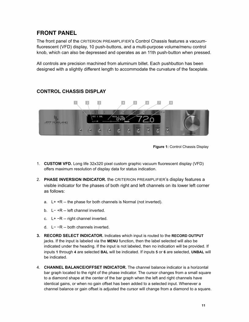
FRONT PANELThe front panel of the CRITERION PREAMPLIFIER’s Control Chassis features a vacuum-fluorescent (VFD) display, 10 push-buttons, and a multi-purpose volume/menu control knob, which can also be depressed and operates as an 11th push-button when pressed.
All controls are precision machined from aluminum billet. Each pushbutton has been designed with a slightly different length to accommodate the curvature of the faceplate.
CONTROL CHASSIS DISPLAY
Figure 1: Control Chassis Display
1. CUSTOM VFD. Long life 32x320 pixel custom graphic vacuum fluorescent display (VFD) offers maximum resolution of display data for status indication.
2. PHASE INVERSION INDICATOR. the CRITERION PREAMPLIFIER’s display features a visible indicator for the phases of both right and left channels on its lower left corner as follows:
a. L+ +R -- the phase for both channels is Normal (not inverted).
b. L− +R -- left channel inverted.
c. L+ −R -- right channel inverted.
d. L− −R -- both channels inverted.
3. RECORD SELECT INDICATOR. Indicates which input is routed to the RECORD OUTPUT jacks. If the input is labeled via the MENU function, then the label selected will also be indicated under the heading. If the input is not labeled, then no indication will be provided. If inputs 1 through 4 are selected BAL will be indicated. If inputs 5 or 6 are selected, UNBAL will be indicated.
4. CHANNEL BALANCE/OFFSET INDICATOR. The channel balance indicator is a horizontal bar graph located to the right of the phase indicator. The cursor changes from a small square to a diamond shape at the center of the bar graph when the left and right channels have identical gains, or when no gain offset has been added to a selected input. Whenever a channel balance or gain offset is adjusted the cursor will change from a diamond to a square.
11
Each increment of the cursor is equal to one-half dB of gain offset of each channel, or a one dB difference between right and left channels.
5. INPUT NUMBER INDICATOR. Indicates which input number is routed to the MAIN OUTPUT 1/2 jacks. If inputs 1 through 4 are selected BAL will be indicated. If inputs 5 or 6 are selected, UNBAL will be indicated.
6. INPUT LABEL INDICATOR. If the input is labeled via the MENU function, then the label selected will be indicated. A complete list of input names is provided in the MENU when the menu function is selected.
7. BATTERY CHARGE STATUS. An 8-segment “gas gauge” indicates the approximate battery capacity when operating in battery mode. It is fully lit when the battery charge is between 87.5% and full. The outline appears empty when the battery’s charge is depleted to less than 12.5%. When battery mode is selected, a B will appear to the left of the gas gauge. When RUN ON AC/CHARGE mode is selected from the MENU, the gas gauge will sequentially increment during battery recharging until the batteries are fully charged. At full charge the gas gauge will be solid.
8. VOLUME/MUTE INDICATOR. This display shows the current volume of the selected input numerically, from 00.0 to 99.5, in 0.5 dB increments. When the preamp is muted the volume indicator numbers will be surrounded by corner brackets which indicates that the selected volume will be decreased by 20 dB. The selected volume numbers will also be decreased by 20. When the preamp is fully muted the original volume indicator numbers will be surrounded by full brackets which indicates that the selected volume will be decreased to zero.
12
CONTROL CHASSIS CONTROLS
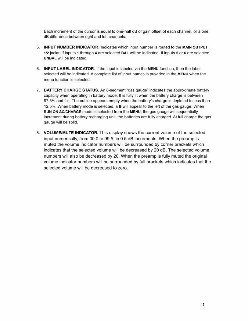
Figure 2: Control Chassis Controls
1. INPUT BUTTONS 1-6. The main input number is selected by pressing the desired input button.
2. RECORD PUSHBUTTON. Enters the RECORD SELECT mode. The record input number is selected by pressing the front panel’s RECORD button and then pressing the desired input button. This can also be done by choosing RECORD SELECT from the MENU. The RECORD SELECT MODE persists until a main input number is selected.
3. MENU PUSHBUTTON. Enters MENU mode. Also used to select the MENU option and exit the MENU mode.
4. STANDBY PUSHBUTTON. Turns display off and mutes the preamplifier. Typically used to extend the life of the display while maintaining the preamplifier circuitry in a powered status.
5. MUTE PUSHBUTTON. Depressing the MUTE button once will reduce the volume by 20 dB. Depressing the MUTE button a second time will fully mute the volume. Depressing the MUTE button a third time will return the volume to the original unmuted condition. Depressing and holding the MUTE button for approximately 10 seconds forces a hardware reset.
6. VOLUME/ENTER CONTROL KNOB. Rotation of the volume control knob clockwise will increase the output level of the CRITERION PREAMPLIFIER. Rotation of the knob counter-clockwise will decrease the output level. The CRITERION PREAMPLIFIER features a dual-range volume control system. Rotating the volume knob slowly will cause the volume to increase or decrease in small, precise steps. Rotating the knob abruptly will result in large, immediate changes to the output level. Depressing the volume control knob will enter and exit the CRITERION PREAMPLIFIER’s MENU mode, duplicating the function of the MENU button.
In MENU mode, rotating the volume knob will scroll through the CRITERION PREAMPLIFIER’s menu and submenus.
13
MENU OPTIONS
Several buttons enter and exit the MENU: The front-panel’s MENU button; the handheld remote transmitter ENTER and EXIT buttons; and the front panel VOLUME/ENTER knob. From the display’s main screen, pressing any of the MENU buttons enters the MENU mode. Once in MENU mode, either the VOLUME/ENTER knob or the handheld remote transmitter’s Navigation Up () or Down () buttons scroll through the MENU choices. The menu text scrolls up or down. After scrolling to the desired menu item, pressing any MENU button again performs that function and exits the MENU mode.
CANCEL MENU. Pressing any of the MENU buttons will cancel the MENU mode and return to the display’s main screen.
BALANCE. Adjusts the difference between left and right signal levels in 1.0dB steps. Adjusting the cursor to the left increases the left channel’s gain in 0.5dB increments, while decreasing the right channel’s gain in 0.5dB increments, and vice versa. The adjustment in balance will not affect the overall volume level. Adjusting the balance for any input will adjust the balance for all inputs. Any balance adjustment will be saved in the internal memory of the preamplifier even if the power is shut off. Up to a maximum of +/-20dB offset can be achieved.
RUN ON BATTERY. Operates all preamplifier circuitry on it’s own internal battery power supply. Also, disconnects preamplifier circuitry from it’s internal AC power supply, and discontinues the charging of the batteries. Battery operation can also be achieved by pressing the NAVIGATION RIGHT () button on the handheld remote transmitter outside of MENU mode. Pressing the NAVIGATION LEFT () button will return the preamplifier to the RUN ON AC/CHARGE mode. Starting from fully charged, the CRITERION PREAMPLIFIER will run on the battery for approximately 3 to 3.5 hours.
NOTE: NEW BATTERIES WILL USUALLY ACHIEVE MAXIMUM CAPACITY AFTER SEVERAL CHARGE/DISCHARGE CYCLES. WHEN THE CRITERION PREAMPLIFIER IS NEW, OR THE BATTERIES HAVE BEEN REPLACED, FULLY CHARGING AND DISCHARGING THE BATTERIES WILL EXPEDITE THE CALIBRATION OF THE CHARGE MANAGEMENT SYSTEM.
When the battery’s charge is nearly depleted, RUN ON BATTERY is automatically canceled and switches the CRITERION PREAMPLIFIER to RUN ON AC/CHARGE until the battery is fully charged. Charging can be manually canceled by the STOP CHARGING menu option.
RUN ON AC/CHARGE. Starts charging the batteries and operates the CRITERION PREAMPLIFIER from the AC Mains. This can also be achieved by pressing the NAVIGATION LEFT () button on the handheld remote transmitter.
NOTE: THE CHARGE MANAGEMENT CIRCUITS AND FIRMWARE PREVENT OVER-CHARGING OR DEEP DISCHARGING OF THE BATTERIES.
If the CRITERION PREAMPLIFIER is unplugged from the AC mains or the rear panel power switch is turned off, and the battery condition is unknown, the CRITERION PREAMPLIFIER will default to the RUN ON AC/CHARGE mode when AC power is restored.
14
STOP CHARGING. Turns off the charging circuit, but continues to run on AC. This menu selection is optional, as charging is normally terminated automatically.
STANDBY. Enters STANDBY mode. STANDBY mode must be exited by pressing the front panel’s Standby button.
RECORD SELECT. Assigns any input selected from the front panel to the record circuitry and outputs jacks.
PHASE NORMAL. Sets both channels to non-inverting (normal phase). The lower left-hand corner of the display indicates. (L+ +R)
NOTE: ANY OF THE FOUR PHASE OPTIONS CAN BE SELECTED FROM THE MENU. HOWEVER, THE PHASE BUTTON ON THE HANDHELD REMOTE TRANSMITTER SIMPLY TOGGLES BETWEEN PHASE NORMAL AND INVERT BOTH.
INVERT BOTH. Inverts the phase of both channels. (L− −R)
INVERT LEFT. Inverts only the left channel. (L− +R)
INVERT RIGHT. Inverts only the right channel. (L+ −R)
INPUT OFFSET. Adjusts the gain for the most recently selected main input by up to +/−20dB by turning the VOLUME/ENTER knob clockwise or counter-clockwise. The balance bar graph will indicate any degree of adjustment in 0.5dB increments when this mode is selected. When the cursor is returned to center and resumes its diamond shape no input offset adjustment has been made.This feature is particularly useful for sources that have much higher or much lower output levels than normal. Every individual input offset adjustments is automatically stored in the preamplifier internal memory until adjusted to a new value.
OUT 2 OFFSET. Adjusts the gain of the unbalanced (RCA) OUT 2 output relative to the balanced (XLR) MAIN OUTPUTS 1 and 2 by turning the VOLUME/ENTER knob clockwise or counter-clockwise.The balance bar graph will indicate any degree of adjustment in 0.5dB increments when this mode is selected. When the cursor is returned to center and resumes its diamond shape, no OUT 2 OFFSET adjustment has been made. Any OUT 2 OFFSET adjustment is automatically stored in the preamplifier internal memory until adjusted to a new value. Up to a maximum of +/-20dB offset can be achieved.
RECORD OUT LEVEL. Adjusts the level (volume) of the record signal path over the same range as the main signal path.
NAME − . . . . . A variety of names for labeling the Main and Record Inputs is provided. The name chosen is assigned to the last-selected Main or Record Input.
REMOTE DEFAULT. Returns IR receiver frequencies to factory default setting, thereby matching the handheld remote transmitter transmission frequencies when adjusted to factory default setting.
15
REMOTE ALT 1,2, AND 3. Sets IR receiver frequencies to match handheld remote transmitter transmission frequencies when adjusted to corresponding transmitting frequencies.
DISPLAY HIGH/MEDIUM/LOW. Adjusts the brightness of the display in three levels.
DISPLAY ON. Cancels DISPLAY OFF 5s/15s modes and returns the display to the DISPLAY HIGH brightness setting.
DISPLAY OFF 5s. The display remains off during normal operation, and is temporarily activated for 5 seconds whenever any command is issued through the front panel or the handheld remote transmitter.
DISPLAY OFF 15s. The display remains off during normal operation, and is temporarily activated for 15 seconds whenever any command is issued through the front panel or handheld remote transmitter.
FACTORY DEFAULT. Return all preamplifier settings to factory defaults.
CRITERION PREAMPLIFIER FIRMWARE REVISION NUMBER. Indicates current version of the CRITERION PREAMPLIFIER operating system software.
16
REAR PANELCONTROL CHASSIS
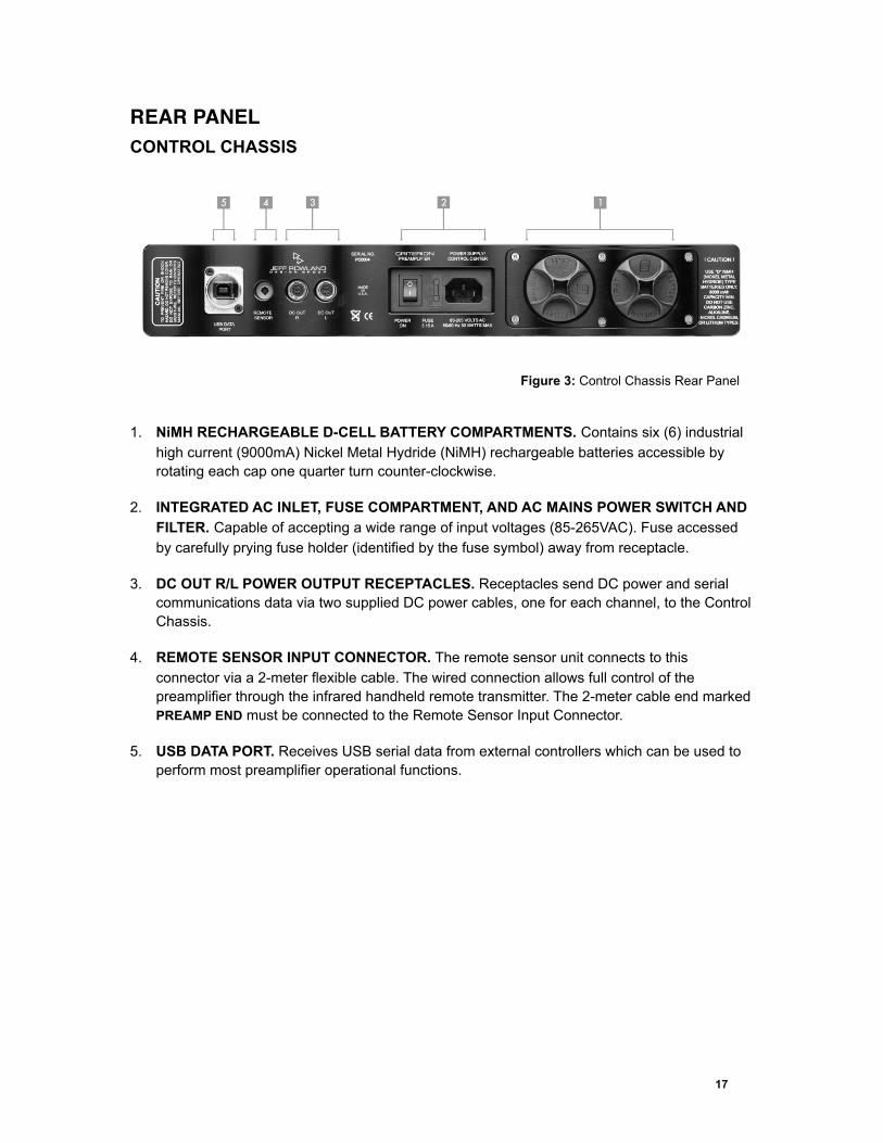
Figure 3: Control Chassis Rear Panel
1. NiMH RECHARGEABLE D-CELL BATTERY COMPARTMENTS. Contains six (6) industrial high current (9000mA) Nickel Metal Hydride (NiMH) rechargeable batteries accessible by rotating each cap one quarter turn counter-clockwise.
2. INTEGRATED AC INLET, FUSE COMPARTMENT, AND AC MAINS POWER SWITCH AND FILTER. Capable of accepting a wide range of input voltages (85-265VAC). Fuse accessed by carefully prying fuse holder (identified by the fuse symbol) away from receptacle.
3. DC OUT R/L POWER OUTPUT RECEPTACLES. Receptacles send DC power and serial communications data via two supplied DC power cables, one for each channel, to the Control Chassis.
4. REMOTE SENSOR INPUT CONNECTOR. The remote sensor unit connects to this connector via a 2-meter flexible cable. The wired connection allows full control of the preamplifier through the infrared handheld remote transmitter. The 2-meter cable end marked PREAMP END must be connected to the Remote Sensor Input Connector.
5. USB DATA PORT. Receives USB serial data from external controllers which can be used to perform most preamplifier operational functions.
17
AUDIO CHASSIS
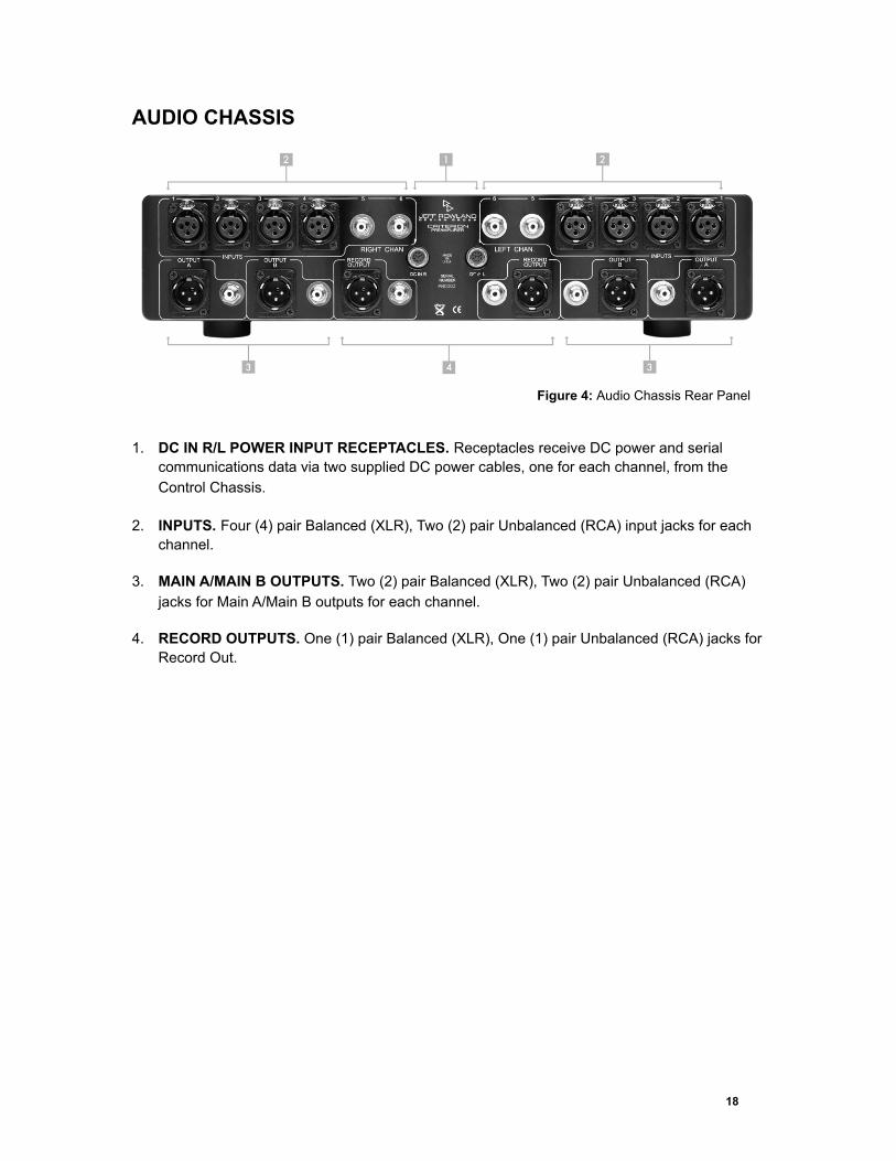
Figure 4: Audio Chassis Rear Panel
1. DC IN R/L POWER INPUT RECEPTACLES. Receptacles receive DC power and serial communications data via two supplied DC power cables, one for each channel, from the Control Chassis.
2. INPUTS. Four (4) pair Balanced (XLR), Two (2) pair Unbalanced (RCA) input jacks for each channel.
3. MAIN A/MAIN B OUTPUTS. Two (2) pair Balanced (XLR), Two (2) pair Unbalanced (RCA) jacks for Main A/Main B outputs for each channel.
4. RECORD OUTPUTS. One (1) pair Balanced (XLR), One (1) pair Unbalanced (RCA) jacks for Record Out.
18
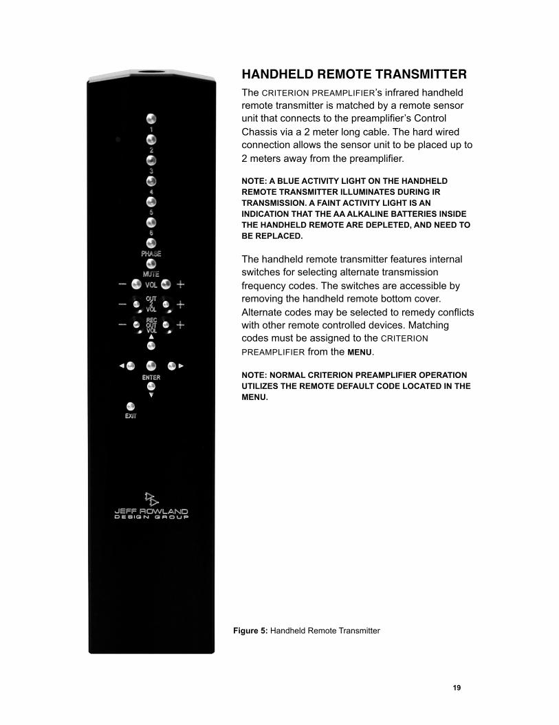
HANDHELD REMOTE TRANSMITTERThe CRITERION PREAMPLIFIER’s infrared handheld remote transmitter is matched by a remote sensor unit that connects to the preamplifier’s Control Chassis via a 2 meter long cable. The hard wired connection allows the sensor unit to be placed up to 2 meters away from the preamplifier.
NOTE: A BLUE ACTIVITY LIGHT ON THE HANDHELD REMOTE TRANSMITTER ILLUMINATES DURING IR TRANSMISSION. A FAINT ACTIVITY LIGHT IS AN INDICATION THAT THE AA ALKALINE BATTERIES INSIDE THE HANDHELD REMOTE ARE DEPLETED, AND NEED TO BE REPLACED.
The handheld remote transmitter features internal switches for selecting alternate transmission frequency codes. The switches are accessible by removing the handheld remote bottom cover. Alternate codes may be selected to remedy conflicts with other remote controlled devices. Matching codes must be assigned to the CRITERION
PREAMPLIFIER from the MENU.
NOTE: NORMAL CRITERION PREAMPLIFIER OPERATION UTILIZES THE REMOTE DEFAULT CODE LOCATED IN THE MENU.
19
Figure 5: Handheld Remote Transmitter
REMOTE TRANSMITTER CONTROLS
BUTTONS 1 THROUGH 6. Selects the Main Input number. If front panel RECORD button is pressed, or the RECORD SELECT menu option is selected, the handheld remote buttons #1 through #6 will select the Record Input Number.
PHASE. Toggles between Phase Normal (L+ +R) and Invert Both (L− −R).
MUTE. the CRITERION PREAMPLIFIER’s mute function can be controlled by pressing the dedicated MUTE button featured on the handheld remote transmitter.
VOLUME +/−. Normally adjusts the Main Input volume. In RECORD OUT LEVEL mode it adjusts the record volume.
OUT 2 VOL +/−. Adjusts the level of the unbalanced RCA main outputs relative to the balanced Main Out 1 outputs (XLR/RCA), and Main Output 2 XLR output. Press ENTER or EXIT to leave this mode.
REC OUT VOLUME +/−. Pressing either button automatically enters the REC OUT LEVEL menu mode and then adjusts the level of the RECORD outputs (XLR/RCA). Press ENTER or EXIT to leave this mode.
UP-DOWN ARROWS. /. In MENU mode scrolls the menu text up or down.
LEFT RIGHT ARROWS. / In display’s main screen - switches to RUN ON AC/CHARGE or RUN ON BATTERY mode. In the BALANCE menu mode - shifts the outputs to the left or right. In the INPUT OFFSET or OUT 2 OFFSET menu modes - adjusts the gain up or down.
ENTER. Performs the same function as the front panel’s MENU button.
EXIT. Exits any MENU function.
INTERNAL SWITCHES
Selects the Remote Frequency (custom code) that is transmitted
All Switches Off: Default Remote Code.
Switch 1 ON: Remote Code 1.
Switch 2 ON: Remote Code 2.
Switch 3 ON: Remote Code 3.
Switch 4 ON: Enables blinking “finder” LED.
20
REMOTE TRANSMITTER BATTERY REPLACEMENT
CRITERION PREAMPLIFIER’s handheld remote transmitter is powered by 2 standard alkaline double-A (AA) batteries. When the remote transmission range decreases or no longer operates, the batteries need to be replaced.
Using a standard flat blade screw driver, unfasten the holding screw located in the bottom end of the transmitter unit.
Remove the spring-loaded cover.
Remove both AA batteries.
Orient the remote transmitter with the keypad facing up, and with the battery compartment towards you.
Insert a fresh battery into the left barrel with negative pole (flat end) first.
Insert a fresh battery into the right barrel with positive pole (button end) first.
Install the spring-loaded cover.
Gently refasten the holding screw. Do not over-tighten.
21
GENERAL OPERATIONSPOWERING ON AND OFF
The CRITERION PREAMPLIFIER employs a master power switch on the rear panel of its Control Chassis. The rocker-type switch is integrated in the 15A female IEC receptacle module, mounted in an inset area immediately to the left of the twin battery holders.
When the master power switch is moved to the ‘on’ position, the CRITERION PREAMPLIFIER tests its circuitry for several seconds, then enables the active inputs and outputs. The preamplifier is best left powered on indefinitely to ensure optimum operating characteristics, and to help maintain the batteries in a fully charged condition.
NOTE: IF THE CRITERION PREAMPLIFIER IS IN RUN-ON BATTERY MODE, IT WILL CONTINUE TO OPERATE EVEN WHEN THE POWER SWITCH IS TURNED-OFF.
SETTING MUTE
Pressing the MUTE button once on either the control panel or remote transmitter reduces the main volume by 20dB, and decreases the volume indicator by 20.0 counts. The display shows the volume indicator surrounded by corner brackets.
Pressing MUTE button a second time mutes the main volume completely. The volume indicator on the display returns to the normal count, but it is surrounded by full brackets.
Pressing MUTE button a third time returns the CRITERION PREAMPLIFIER’s volume to the original level. Brackets will disappear from the indicator, and the indicator will return to its original count.
CHANNEL BALANCE
There are two methods to adjust left/right channel balance on the CRITERION PREAMPLIFIER:
From the Preamplifier Control Chassis
Enter MENU. Scroll to and select BALANCE. Turn the main volume knob clockwise for a right shift or counter-clockwise for a left shift. Exit MENU.
From the Handheld Remote Transmitter
Enter MENU. Scroll to and select BALANCE. Press either volume buttons (+/-) on the handheld remote transmitter. Each BALANCE key press on the remote transmitter reduces the gain by 0.5dB on one channel, while increasing the gain on the opposite channel by the same amount. This results in a detectable shift of the sonic image towards the desired side.
22
NOTE: BALANCE ADJUSTMENTS MADE ON ANY INPUT WILL BE APPLIED TO ALL INPUTS AND IS SAVED EVEN WHEN THE PREAMPLIFIER IS POWERED DOWN.
SWITCHING BETWEEN AC MODE AND BATTERY MODE
DC Battery power mode operation can be selected either from the CRITERION PREAMPLIFIER’s front panel or from its handheld remote transmitter.
From the front panel:
Enter MENU mode and select RUN ON BATTERY. Press MENU to activate BATTERY MODE.
Enter MENU mode and select RUN ON AC/CHARGE. Press MENU to activate AC MODE.
From the handheld remote transmitter, while no menu functions are selected on the CRITERION PREAMPLIFIER’s display, press the NAVIGATION RIGHT () button to activate BATTERY MODE operation. Press the NAVIGATION LEFT () button to activate AC MODE operation.
NOTE: THE CRITERION PREAMPLIFIER DOES NOT SWITCH AUTOMATICALLY FROM AC TO BATTERY MODE WHEN THE BATTERIES ARE FULLY CHARGED.
RECORD SELECT INPUT ASSIGNMENT
Enter RECORD SELECT MODE by pressing the RECORD pushbutton on the main control panel, or by selecting RECORD SELECT from the CRITERION PREAMPLIFIER’s menu.
Press any input button, ranging from #1 to #6, on the control panel or on the CRITERION PREAMPLIFIER’s remote transmitter to complete the assignment. The selected input routed to the RECORD-OUT jacks will be confirmed on the left-hand side of the display. The CRITERION PREAMPLIFIER will automatically return to standard operation.
ADJUSTING RECORD OUT LEVEL
Enter MENU. Scroll and select RECORD OUT LEVEL. The main volume indicator shows the gain of the selected input routed to the RECORD-OUT jacks. Adjust the level with the front panel’s volume knob or the remote’s REC OUT VOL +/− buttons.
The RECORD OUT LEVEL mode is also entered by pressing either of the remote’s REC OUT VOL +/− buttons. Exit by pressing any of the MENU buttons.
INDEPENDENT PHASE INVERSION
Enter MENU. Scroll and select desired phase condition. Possible phase conditions include PHASE NORMAL, INVERT BOTH, INVERT RIGHT, and INVERT LEFT as indicated on the display. Exit by pressing any of the MENU buttons.
The CRITERION PREAMPLIFIER's independent phase inversion control on each channel is an important system debugging tool. It facilitates effective troubleshooting of phase inversion
23
problems on associated electronic components, speakers, speaker wires, and interconnects, particularly in complex audio systems consisting of multiple amplifiers and multiple source components.
SETTING OUT 2 OFFSET
Enter MENU. Scroll and select OUT 2 OFFSET. The balance indicator bar temporarily shows the amount of offset. Adjust the offset with the front panel’s knob or the remote’s NAVIGATION RIGHT () NAVIGATION LEFT () buttons. Exit by pressing any of the MENU buttons.
SETTING INPUT OFFSET
Enter MENU. Scroll and select INPUT OFFSET. The balance indicator bar temporarily shows the amount of offset. Adjust the offset with the front panel’s knob or the remote’s NAVIGATION RIGHT () NAVIGATION LEFT () buttons. Exit by pressing any of the MENU buttons.
ADJUSTING OUT 2 OFFSET
Enter MENU. Scroll and select OUT 2 OFFSET. The balance indicator bar temporarily shows the amount of offset. Adjust the offset with the front panel’s knob or the remote’s NAVIGATION RIGHT () NAVIGATION LEFT () buttons. Exit by pressing any of the MENU buttons.
FACTORY RESTORE
Enter MENU. Scroll and select FACTORY DEFAULTS. This action returns all configuration and adjustments to the original factory-set default values: Main and record volume levels are set to 0dB, input device name assignments are cleared, input and output gain offset adjustments are zeroed, and the CRITERION PREAMPLIFIER is returned to AC operation.
NOTE: PRESSING AND HOLDING THE MUTE BUTTON ON THE CRITERION PREAMPLIFIER'S CONTROL CHASSIS FOR APPROXIMATELY 10 SECONDS, THEN RELEASING, WILL FORCE A RESET OF THE PREAMPLIFIER’S HARDWARE AND RETURN MAIN AND RECORD VOLUME TO 0dB.
24
BATTERY MODE AND DC RECHARGEABLE BATTERIESBATTERY MODE PLAYING TIME
The CRITERION PREAMPLIFIER can operate in BATTERY MODE for 3 to 3.5 hours of playing time when batteries have been fully charged. When the battery charge is reduced to 12.5%, the preamplifier switches automatically to AC operation and commences to recharge its batteries. Battery run time can be increased approximately 20% when the front panel VFD display is switched off, or the unit is placed in STANDBY mode.
BATTERY TYPE
The CRITERION PREAMPLIFIER has been designed to operate with industrial grade high current NiMH rechargeable D-cells with a capacity of 9 ampere hours. Replacement rechargeable D-cell batteries compatible with the CRITERION PREAMPLIFIER can be ordered directly from the JRDG factory.
WARNING: NO OTHER BATTERY TYPES (CARBON ZINC, ALKALINE, NiCAD, LITHIUM) CAN BE USED IN THE CRITERION. ATTEMPTING TO DO SO MAY CAUSE FIRES, OR SEVERE DAMAGE TO THE PREAMPLIFIER. ANY DAMAGE TO THE CRITERION PREAMPLIFIER RESULTING FROM THE USE OF UNAPPROVED BATTERIES IS NOT COVERED BY THE JRDG WARRANTY.
AUTO-SWITCH
When battery level is depleted to approximately 12.5% of its full charge, the CRITERION switches automatically to AC MODE and commences to recharge its battery while playback continues uninterrupted.
BATTERY LIFE
The NiMH memory-free feature of the batteries, and the CRITERION PREAMPLIFIER’s advanced power management system, guarantee an extreme long life to the CRITERION PREAMPLIFIER’s batteries.(Up to 6 years under normal use).
REPLACING BATTERIES
Twist battery caps one quarter turn counter-clockwise and remove. Tilt the front of the CRITERION PREAMPLIFIER up so that three batteries slide out from each compartment. Place three new batteries into each compartment with positive (button end) facing the rear of the CRITERION PREAMPLIFIER. Install battery caps by pushing in and rotating one quarter turn clockwise.
25
SPECIFICATIONS
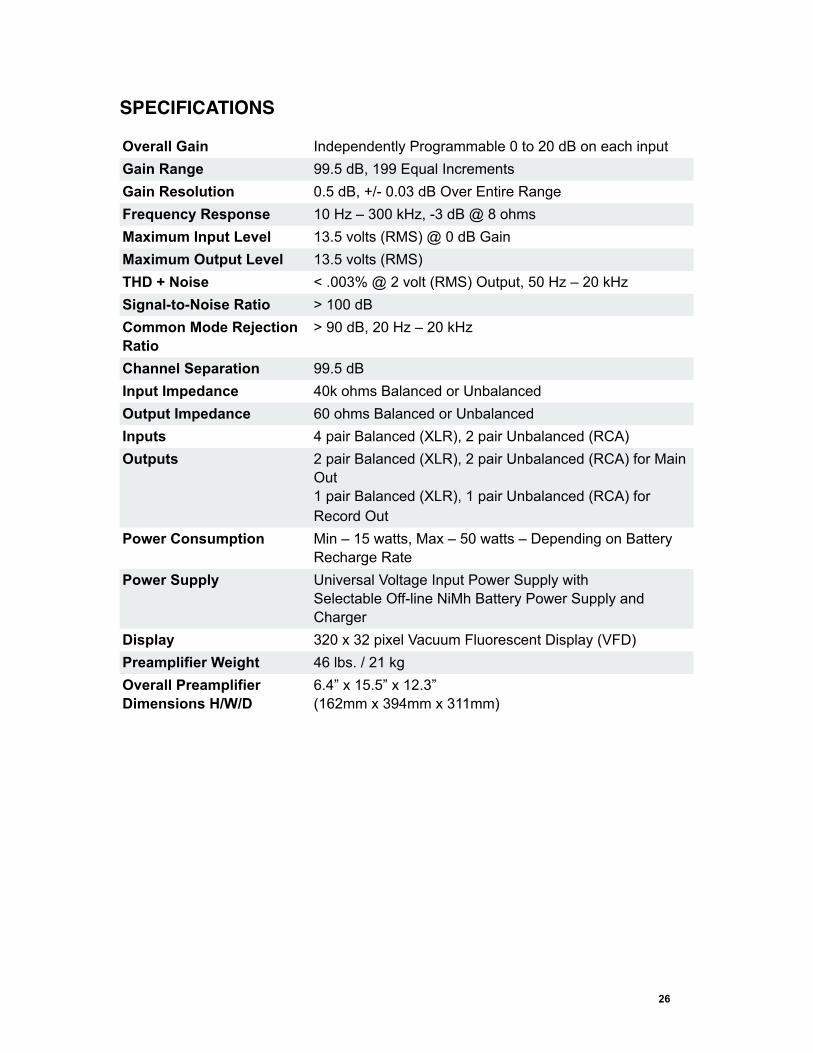
Overall Gain Independently Programmable 0 to 20 dB on each input Gain Range 99.5 dB, 199 Equal IncrementsGain Resolution 0.5 dB, +/- 0.03 dB Over Entire RangeFrequency Response 10 Hz – 300 kHz, -3 dB @ 8 ohmsMaximum Input Level 13.5 volts (RMS) @ 0 dB GainMaximum Output Level 13.5 volts (RMS)THD + Noise < .003% @ 2 volt (RMS) Output, 50 Hz – 20 kHzSignal-to-Noise Ratio > 100 dBCommon Mode Rejection Ratio
> 90 dB, 20 Hz – 20 kHz
Channel Separation 99.5 dB Input Impedance 40k ohms Balanced or UnbalancedOutput Impedance 60 ohms Balanced or UnbalancedInputs 4 pair Balanced (XLR), 2 pair Unbalanced (RCA)Outputs 2 pair Balanced (XLR), 2 pair Unbalanced (RCA) for Main
Out1 pair Balanced (XLR), 1 pair Unbalanced (RCA) for Record Out
Power Consumption Min – 15 watts, Max – 50 watts – Depending on Battery Recharge Rate
Power Supply Universal Voltage Input Power Supply withSelectable Off-line NiMh Battery Power Supply and Charger
Display 320 x 32 pixel Vacuum Fluorescent Display (VFD)Preamplifier Weight 46 lbs. / 21 kgOverall Preamplifier Dimensions H/W/D
6.4” x 15.5” x 12.3” (162mm x 394mm x 311mm)
26


![C22 Preamplifier Complete User Manual - Analog Metricanalogmetric.com/download/C22 Preamplifier Complete User Manual.pdf · [C22 VACUUM TUBE PREAMPLIFIER COMPLETE USER MANUAL ]](https://img.dokumen.tips/doc/110x75/5ad3f8607f8b9abd6c8eae98/c22-preamplifier-complete-user-manual-analog-preamplifier-complete-user-manualpdfc22.jpg)


![C 165BEE Stereo Preamplifier - NAD Electronics · • Sealed Reed Relays for Input Switching • Heavy Gauge Steel Chassis • Bass and Treble Controls with Defeat Switch (bypass]](https://img.dokumen.tips/doc/110x75/5fc655f09e1a8763c45990f0/c-165bee-stereo-preamplifier-nad-electronics-a-sealed-reed-relays-for-input.jpg)