Embed Size (px)
Citation preview

ArbeitskreisMessdatenverarbeitungFahrzeugsicherheit
Crash AnalysisCriteria Description
Version 2
Crash Analysis Criteria
Data Processing Vehicle Safety Workgroup
Version 2
October 2006 EditionSubject to Changes

Measured data processing vehicle safety workgroup, Algorithm workgroup: D. Cichos, bast; D. de Vogel, Ford; M. Otto, TÜV Rheinland; O. Schaar, Delphi; S. Zölsch, National Instruments, in cooperation with the Task Force ISO TS 13499 (ISO-MME)
This documentation is available from the following address:
Bundesanstalt für Straßenwesen, Brüderstraße 53,D-51427 Bergisch Gladbach,Tel.: +49 (0)2204 / 43624, Fax: +49 (0)2204 / 43687
This documentation has been compiled with the greatest care. We are grateful for information about errors, new methods, and new laws. We do not accept liability for incorrect information.
© 1995-2006 Workgroup Data Processing Vehicle Safety. All Rights Reserved.

© Data Processing Vehicle Safety Workgroup — Crash Analysis Criteria Version 2 iii
Contents
Chapter 1Crash Analysis Criteria
Explanations to ISO TS 13499 ......................................................................................1-1
Chapter 2Description of the Head Criteria
HIC.................................................................................................................................2-2HAC ...............................................................................................................................2-6HIC(d) ............................................................................................................................2-9HPC................................................................................................................................2-12HCD ...............................................................................................................................2-15
Chapter 3Description of the Neck Criteria
MOC ..............................................................................................................................3-2MTO...............................................................................................................................3-6Time at Level ................................................................................................................3-10NIC (Front Impact ECE)................................................................................................3-12NIC (Front Impact EuroNCAP).....................................................................................3-15NIC (Front Impact FMVSS) ..........................................................................................3-19NIJ..................................................................................................................................3-22NIC (Rear Impact) .........................................................................................................3-27Nkm ...............................................................................................................................3-30LNL ...............................................................................................................................3-32
Chapter 4Description of the chest criteria
VC..................................................................................................................................4-2THPC .............................................................................................................................4-8TTI(d).............................................................................................................................4-10ThAC .............................................................................................................................4-13CTI .................................................................................................................................4-16ThCC or TCC.................................................................................................................4-19RDC ...............................................................................................................................4-21CDR (TWG) ..................................................................................................................4-24

Contents
iv © Data Processing Vehicle Safety Workgroup — Crash Analysis Criteria Version 2
Chapter 5Description of the Criteria for the Lower Extremities
APF................................................................................................................................ 5-2PSPF .............................................................................................................................. 5-4FFC (ECE)..................................................................................................................... 5-6FFC (EuroNCAP).......................................................................................................... 5-9TI ................................................................................................................................... 5-12TCFC ............................................................................................................................. 5-18
Chapter 6Description of Additional Criteria
Xms................................................................................................................................ 6-2Xg .................................................................................................................................. 6-7Acomp ........................................................................................................................... 6-10Pulse Test ...................................................................................................................... 6-14Gillis Index .................................................................................................................... 6-19NCAP ............................................................................................................................ 6-20EuroNCAP..................................................................................................................... 6-23SI.................................................................................................................................... 6-24Integration...................................................................................................................... 6-27Differentiation ............................................................................................................... 6-28CFC Filters .................................................................................................................... 6-29FIR 100 Filters............................................................................................................... 6-32
Chapter 7Legislation and Directives
Limit Values .................................................................................................................. 7-3

© Data Processing Vehicle Safety Workgroup—Crash Analysis Criteria Version 2 1-1
1Crash Analysis Criteria
The following section contains descriptions of the crash analysis criteria of the workgroup measurement data processing vehicle safety, algorithm workgroup. The order in which the crash analysis criteria are described follows the structure of the human body.
The description of the criteria contains the name, the mathematical calculation, the input unit, the coding in compliance with ISO TS 13499, and a list of rules and regulations of the algorithm.
Note All descriptions are subject to a SAE J1733 conform signal polarity (Sign convention).
Explanations to ISO TS 13499 The ISO TS 13499 describes a simple exchange format for multi-medial data from vehicle safety tests.
The ISO TS 13499 describes the data storage structure and the coding of measurement channels and their attributes in the channel description.
In the current version you can encode the measurement channels as well as the criteria values described in this documentation.
DocumentsThe following table lists the meaning and source of the various single documents that the ISO TS 13499 contains.
Document/Version Contents Source Price
ISO TS 13499 Main Document www.iso.org with costs

Chapter 1 Crash Analysis Criteria
1-2 ©Data Processing Vehicle Safety Workgroup—Crash Analysis Criteria Version 2
*RED - Related Electronic Document
CodesThe above document RED B describes the channel codes used in this documentation. You can download the channel codes as a data base free of charge from standards.iso.org.
The following figure shows the main menu of the ISO TS 13499 data base in the internet.
RED*A Examples and hints
standards.iso.org free of charge
RED B Channel codes
RED C Figures
RED D NHTSA Compatibility
RED E Calculated Channels
Document/Version Contents Source Price

© Data Processing Vehicle Safety Workgroup—Crash Analysis Criteria Version 2 2-1
2Description of the Head Criteria
The following head criteria are described:
• HIC — Head Injury Criterion
• HAC — Head Acceptability Criterion
• HIC(d) — Performance Criterion
• HPC — Head Performance Criterion
• HCD — Head Contact Duration
Chapter 2 Description of the Head Criteria
2-2 ©Data Processing Vehicle Safety Workgroup—Crash Analysis Criteria Version 2
HICHIC is the abbreviation for Head Injury Criterion.
DescriptionThe HIC value is the standardized maximum integral value of the head acceleration. The length of the corresponding time interval is:
• HIC: unlimited
• HIC36: maximum of 36 ms
• HIC15: maximum of 15 ms
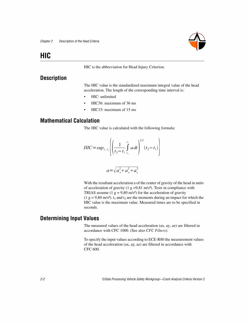
Mathematical CalculationThe HIC value is calculated with the following formula:
With the resultant acceleration a of the center of gravity of the head in units of acceleration of gravity (1 g =9,81 m/s²). Tests in compliance with TRIAS assume (1 g = 9,80 m/s²) for the acceleration of gravity (1 g = 9,80 m/s²). t1 and t2 are the moments during an impact for which the HIC value is the maximum value. Measured times are to be specified in seconds.
Determining Input ValuesThe measured values of the head acceleration (ax, ay, az) are filtered in accordance with CFC 1000. (See also CFC Filters).
To specify the input values according to ECE-R80 the measurement values of the head acceleration (ax, ay, az) are filtered in accordance with CFC 600.
Chapter 2 Description of the Head Criteria
© Data Processing Vehicle Safety Workgroup—Crash Analysis Criteria Version 2 2-3
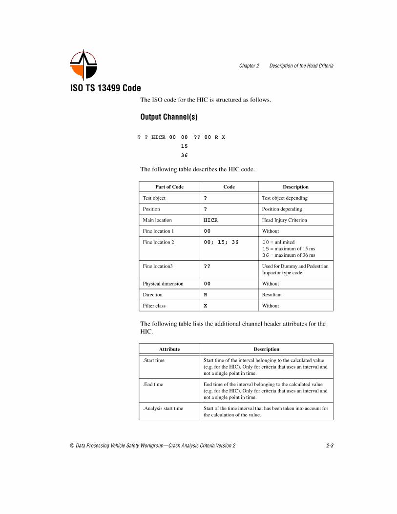
ISO TS 13499 CodeThe ISO code for the HIC is structured as follows.
Output Channel(s)
The following table describes the HIC code.
The following table lists the additional channel header attributes for the HIC.
? ? HICR 00 00 ?? 00 R X
15
36
Part of Code Code Description
Test object ? Test object depending
Position ? Position depending
Main location HICR Head Injury Criterion
Fine location 1 00 Without
Fine location 2 00; 15; 36 00 = unlimited 15 = maximum of 15 ms36 = maximum of 36 ms
Fine location3 ?? Used for Dummy and Pedestrian Impactor type code
Physical dimension 00 Without
Direction R Resultant
Filter class X Without
Attribute Description
.Start time Start time of the interval belonging to the calculated value (e.g. for the HIC). Only for criteria that uses an interval and not a single point in time.
.End time End time of the interval belonging to the calculated value (e.g. for the HIC). Only for criteria that uses an interval and not a single point in time.
.Analysis start time Start of the time interval that has been taken into account for the calculation of the value.

Chapter 2 Description of the Head Criteria
2-4 ©Data Processing Vehicle Safety Workgroup—Crash Analysis Criteria Version 2
Input Channel(s)? ? HEAD 00 00 ?? AC X A : Head Acceleration X, CFC 1000 ? ? HEAD 00 00 ?? AC Y A : Head Acceleration Y, CFC 1000? ? HEAD 00 00 ?? AC Z A : Head Acceleration Z, CFC 1000? ? HEAD 00 00 ?? AC X B : Head Acceleration X, CFC 600,
(ECE R80)? ? HEAD 00 00 ?? AC Y B : Head Acceleration Y, CFC 600,
(ECE R80)? ? HEAD 00 00 ?? AC Z B : Head Acceleration Z, CFC 600,
(ECE R80)
Example Codes? ? HICR 00 15 ?? 00 R X : HIC Value (no window limit)? ? HICR 00 15 ?? 00 R X : HIC 15ms Value? ? HICR 00 36 ?? 00 R X : HIC 36ms Value? ? HICR 00 15 PA 00 R X : HIC 15ms Adult Head Impactor? ? HICR 00 15 PB 00 R X : HIC 15ms ACEA Head Impactor? ? HICR 00 15 PC 00 R X : HIC 15ms ACEA Head Impactor
Relevant Laws and Regulations• FMVSS 208, S6.2
• SAE J2052, 3.2
• SAE J1727,3.6
• ISO/TC22/SC12/WG3 N 282 Issued 1990-03-16
• ADR69/00, 5.3.1
• ECE-R80, Anlage 4, 1
• ECE-R22, 7.3.2.5
.Analysis end time End of the time interval that has been taken into account for the calculation of the value.
.Channel 001
.Channel 002
.Channel 003
ISO Code of the first channel used for the calculation. Order of the channels used is arbitrary. Filtering of the channel should be indicated by the right filter class in ISO code at position 16.
.Filter Filter used: Only if all channels has been filtered with the same channel class! This is redundant to the information given in the ISO codes of each channel but easy to observe in the file.
Attribute Description

Chapter 2 Description of the Head Criteria
© Data Processing Vehicle Safety Workgroup—Crash Analysis Criteria Version 2 2-5
• EuroNCAP, Front Impact, 10, 10.1
• EuroNCAP, Side Impact, 10, 10.1
• EuroNCAP, Pole Side Impact, 10, 10.1
• EuroNCAP, Assessment Protocol, 5
• EuroNCAP, Pedestrian Testing Protocol, 10.2.3.4
• TRIAS 47, Frontal Impact, 2-6
• TRIAS 63, Pedestrian Impact, 2.4
Chapter 2 Description of the Head Criteria
2-6 ©Data Processing Vehicle Safety Workgroup—Crash Analysis Criteria Version 2
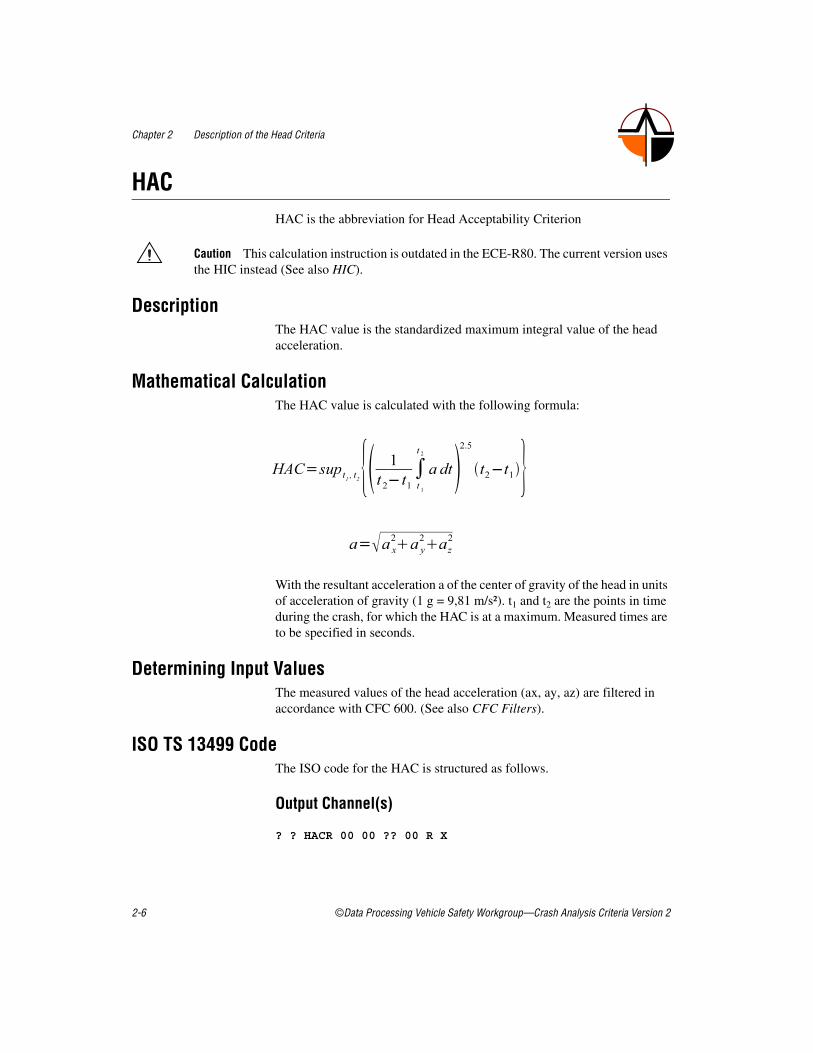
HACHAC is the abbreviation for Head Acceptability Criterion
Caution This calculation instruction is outdated in the ECE-R80. The current version uses the HIC instead (See also HIC).
DescriptionThe HAC value is the standardized maximum integral value of the head acceleration.
Mathematical CalculationThe HAC value is calculated with the following formula:
With the resultant acceleration a of the center of gravity of the head in units of acceleration of gravity (1 g = 9,81 m/s²). t1 and t2 are the points in time during the crash, for which the HAC is at a maximum. Measured times are to be specified in seconds.
Determining Input ValuesThe measured values of the head acceleration (ax, ay, az) are filtered in accordance with CFC 600. (See also CFC Filters).
ISO TS 13499 CodeThe ISO code for the HAC is structured as follows.
Output Channel(s)
? ? HACR 00 00 ?? 00 R X

Chapter 2 Description of the Head Criteria
© Data Processing Vehicle Safety Workgroup—Crash Analysis Criteria Version 2 2-7
The following table describes the HAC code.
The following table lists the additional channel header attributes for the HAC.
Input Channel(s)? ? HEAD 00 00 ?? AC X B : Head Acceleration X, CFC 600
Part of Code Code Description
Test object ? Test object depending
Position ? Position depending
Main location HACR Head Acceptability Criterion
Fine location 1 00 Without
Fine location 2 00 00 = unlimited
Fine location3 ?? Dummy type dependent
Physical dimension 00 Without
Direction R Resultant
Filter class X Without
Attribute Description
.Start time Start time of the interval belonging to the calculated value (e.g. for the HIC). Only for criteria that uses an interval and not a single point in time.
.End time End time of the interval belonging to the calculated value (e.g. for the HIC). Only for criteria that uses an interval and not a single point in time.
.Analysis start time Start of the time interval that has been taken into account for the calculation of the value.
.Analysis end time End of the time interval that has been taken into account for the calculation of the value.
.Channel 001
.Channel 002
.Channel 003
ISO Code of the first channel used for the calculation. Order of the channels used is arbitrary. Filtering of the channel should be indicated by the right filter class in ISO code at position 16.
.Filter Filter used: Only if all channels has been filtered with the same channel class! This is redundant to the information given in the ISO codes of each channel but easy to observe in the file.

Chapter 2 Description of the Head Criteria
2-8 ©Data Processing Vehicle Safety Workgroup—Crash Analysis Criteria Version 2
? ? HEAD 00 00 ?? AC Y B : Head Acceleration Y, CFC 600? ? HEAD 00 00 ?? AC Z B : Head Acceleration Z, CFC 600
Example Codes1 1 HACR 00 00 H3 00 R X : Head Acceptability Criterion 50%
Pos112 3 HACR 00 00 HM 00 R X : Head Acceptability Criterion 95%
Pos23
Relevant Laws and Regulations• ECE-R80, 5.2.2.1.1
• ECE-R80, Annex 7, 1.1
• Richtlinie 74/408/EWG, Anhang III Anlage 4, 1.1

Chapter 2 Description of the Head Criteria
© Data Processing Vehicle Safety Workgroup—Crash Analysis Criteria Version 2 2-9
HIC(d)HIC(d) is the Performance Criterion
DescriptionThe HIC(d) value is the weighted standardized maximum integral value of the head acceleration and is calculated from the HIC36 value.
Mathematical CalculationThe HIC(d) value is calculated with the following formula:
Determining Input ValuesThe measured values of the head acceleration (ax, ay, az) are filtered in accordance with CFC 1000. (See also CFC Filters).
ISO TS 13499 CodeThe ISO code for the HIC(d) is structured as follows.
Output Channel(s)
The following table describes the HIC(d) code.
with HIC36 HIC 36 value (See also HIC)
? ? HICR 00 HD ?? 00 R X
Part of Code Code Description
Test object ? Test object depending
Position ? Position depending
Main location HICR Head Injury Criterion
Fine location 1 00 Without
Fine location 2 HD Head Performance Criterion
Fine location3 ?? Dummy type dependent

Chapter 2 Description of the Head Criteria
2-10 ©Data Processing Vehicle Safety Workgroup—Crash Analysis Criteria Version 2
The following table lists the additional channel header attributes for the HIC(d) .
Input Channel(s)? ? HEAD 00 00 ?? AC X A : Head Acceleration X, CFC 1000? ? HEAD 00 00 ?? AC Y A : Head Acceleration Y, CFC 1000? ? HEAD 00 00 ?? AC Z A : Head Acceleration Z, CFC 1000
Example Codes1 1 HICR 00 HD H3 00 R X : HIC(d) Free Motion Headform,
(FMVSS201)
Physical dimension 00 Without
Direction R Resultant
Filter class X Without
Attribute Description
.Start time Start time of the interval belonging to the calculated value (e.g. for the HIC). Only for criteria that uses an interval and not a single point in time.
.End time End time of the interval belonging to the calculated value (e.g. for the HIC). Only for criteria that uses an interval and not a single point in time.
.Analysis start time Start of the time interval that has been taken into account for the calculation of the value.
.Analysis end time End of the time interval that has been taken into account for the calculation of the value.
.Channel 001
.Channel 002
.Channel 003
ISO Code of the first channel used for the calculation. Order of the channels used is arbitrary. Filtering of the channel should be indicated by the right filter class in ISO code at position 16.
.Filter Filter used: Only if all channels has been filtered with the same channel class! This is redundant to the information given in the ISO codes of each channel but easy to observe in the file.
Part of Code Code Description

Chapter 2 Description of the Head Criteria
© Data Processing Vehicle Safety Workgroup—Crash Analysis Criteria Version 2 2-11
Relevant Laws and Regulations• FMVSS 201, S7
• NHTSA 49 CFR 571[Docket No. 92-28; Notice8], [RIN No. 2127-AG07]; S7
• NHTSA 49 CFR 571,572,589[Docket No. 92-28; Notice7], [RIN No. 2127-AB85]; S7

Chapter 2 Description of the Head Criteria
2-12 ©Data Processing Vehicle Safety Workgroup—Crash Analysis Criteria Version 2
HPCHPC is the abbreviation for Head Performance Criterion (criterion for the head strain).
DescriptionThe HPC value is the standardized maximum integral value of the head acceleration.
The HPC value is identical to the HIC value (See also HIC).
Mathematical CalculationThe HPC value is calculated with the following formula:
With the resultant acceleration a of the center of gravity of the head in units of acceleration of gravity (1 g =9,81 m/s²).
Frontal, side impactIf there was no head contact, this criterion is fulfilled.
If the beginning of the head contact can be determined satisfactorily, t1 and t2 are the two time points, specified in seconds, which define a period between the beginning of the head contact and the end of the recording, at which the HPC36 (max. 36ms) is at its maximum.
If the beginning of the head contact cannot be determined satisfactorily, t1 and t2 are the two time points, expressed in seconds, which define a period between the beginning of the head contact and the end of the recording, at which the HPC36 is at its maximum.
Pedestrian protectionThe corresponding time interval is a maximum of 15ms (HPC15).

Chapter 2 Description of the Head Criteria
© Data Processing Vehicle Safety Workgroup—Crash Analysis Criteria Version 2 2-13
Determining Input ValuesThe measured values of the head acceleration (ax, ay, az) are filtered in accordance with CFC 1000. (See also CFC Filters).
ISO TS 13499 CodeThe ISO code for the HPC is structured as follows.
Output Channel(s)
The following table describes the HPC code.
The following table lists the additional channel header attributes for the HPC.
? ? HPCR 00 15 ?? 00 R X
36
Part of Code Code Description
Test object ? Test object depending
Position ? Position depending
Main location HPCR Head Performance Criterion
Fine location 1 00 Without
Fine location 2 15; 36 15 = maximum of 15 ms36 = maximum of 36 ms
Fine location3 ?? Dummy type dependent
Physical dimension 00 Without
Direction R Resultant
Filter class X Without

Chapter 2 Description of the Head Criteria
2-14 ©Data Processing Vehicle Safety Workgroup—Crash Analysis Criteria Version 2
Input Channel(s)? ? HEAD 00 00 ?? AC X B : Head Acceleration X, CFC 600? ? HEAD 00 00 ?? AC Y B : Head Acceleration Y, CFC 600? ? HEAD 00 00 ?? AC Z B : Head Acceleration Z, CFC 600
Example Codes? ? HPCR 00 15 ?? 00 R X : Head Performance Criterion,
Pedestrian? ? HPCR 00 36 ?? 00 R X : Head Performance Criterion
Relevant Laws and Regulations• Richtlinie 96/79/EG, Anhang II, 3.2.1.1
• Richtlinie 96/79/EG, Anhang II, Anlage 2, 1.2
• ECE-R94, Anhang 4, 1.2
• ECE-R95, 5.2.1.1
• ECE-R95, Anhang 4, Anlage 1, 1.
• Richtlinie 2004/90/EG, 2.10
Attribute Description
.Start time Start time of the interval belonging to the calculated value (e.g. for the HIC). Only for criteria that uses an interval and not a single point in time.
.End time End time of the interval belonging to the calculated value (e.g. for the HIC). Only for criteria that uses an interval and not a single point in time.
.Analysis start time Start of the time interval that has been taken into account for the calculation of the value.
.Analysis end time End of the time interval that has been taken into account for the calculation of the value.
.Channel 001
.Channel 002
.Channel 003
ISO Code of the first channel used for the calculation. Order of the channels used is arbitrary. Filtering of the channel should be indicated by the right filter class in ISO code at position 16.
.Filter Filter used: Only if all channels has been filtered with the same channel class! This is redundant to the information given in the ISO codes of each channel but easy to observe in the file.

Chapter 2 Description of the Head Criteria
© Data Processing Vehicle Safety Workgroup—Crash Analysis Criteria Version 2 2-15
HCDHCD is the abbreviation for Head Contact Duration.
DescriptionThe HCD value is the standardized maximum integral value of the head acceleration during head contact intervals. The contact intervals are determined using the resultant contact force (calculated from neck force of the upper neck transducer, head acceleration and head mass).
Mathematical CalculationTo determine the contact interval, the resultant contact force F has to be calculated first.
Contact intervals are all the intervals in which a lower threshold value (threshold level = 200N) is constantly exceeded and a lower search level (search level = 500N) is exceeded at least once as the following figure shows.
with m Mass of the head
ai Head acceleration in the i direction
Fi Upper neck force in the i direction

Chapter 2 Description of the Head Criteria
2-16 ©Data Processing Vehicle Safety Workgroup—Crash Analysis Criteria Version 2
The HICj value is calculated for every contact interval Kj
The HCD value is then the maximum HIC value of all the contact intervals.
Determining Input ValuesThe measured values of the head acceleration (ax, ay, az) and the neck force (Fx, Fy, Fz) are filtered in accordance with CFC 1000. (See also CFC Filters).
ISO TS 13499 CodeThe ISO code for the HCD is structured as follows.
Output Channel(s)? ? HECD 00 ?? ?? 00 R X
The following table describes the HPC code.
with tjbeg Start point for contact interval Kj
tjend End time for contact interval Kj
Part of Code Code Description
Test object ? Test object depending
Position ? Position depending
Main location HECD Head Contact Duration
Fine location 1 00 Without
Fine location 2 ?? Fine location 2 dependent
Fine location3 ?? Dummy type dependent
Physical dimension 00 Without

Chapter 2 Description of the Head Criteria
© Data Processing Vehicle Safety Workgroup—Crash Analysis Criteria Version 2 2-17
The following table lists the additional channel header attributes for the HCD.
Input Channel(s)? ? HEAD 00 ?? ?? AC X A : Head Acceleration X, CFC 1000? ? HEAD 00 ?? ?? AC Y A : Head Acceleration Y, CFC 1000? ? HEAD 00 ?? ?? AC Z A : Head Acceleration Z, CFC 1000
Direction R Resultant
Filter class X Without
Attribute Description
.Start time Start time of the interval belonging to the calculated value (e.g. for the HIC). Only for criteria that uses an interval and not a single point in time.
.End time End time of the interval belonging to the calculated value (e.g. for the HIC). Only for criteria that uses an interval and not a single point in time.
.Analysis start time Start of the time interval that has been taken into account for the calculation of the value.
.Analysis end time End of the time interval that has been taken into account for the calculation of the value.
.Channel 001
...
.Channel nnn
ISO Code of the first channel used for the calculation. Order of the channels used is arbitrary. Filtering of the channel should be indicated by the right filter class in ISO code at position 16.
.Filter Filter used: Only if all channels has been filtered with the same channel class! This is redundant to the information given in the ISO codes of each channel but easy to observe in the file.
.Threshold level Specific for Head Contact Duration: Threshold level used for the calculation.Maximum of several HIC calculations for time intervals with head contact. Contact Intervals are identified by the ".Threshold level" and the ".Search level"
.Search level Specific for Head Contact Duration: Search Level used for the calculation.Maximum of several HIC calculations for time intervals with head contact. Contact Intervals are identified by the ".Threshold level" and the ".Search level"
.Mass Specific for Head Contact Duration: Mass value used for the calculation.
Part of Code Code Description

Chapter 2 Description of the Head Criteria
2-18 ©Data Processing Vehicle Safety Workgroup—Crash Analysis Criteria Version 2
? ? NECK UP ?? ?? FO X A : Upper Neck Force X, CFC 1000? ? NECK UP ?? ?? FO Y A : Upper Neck Force Y, CFC 1000? ? NECK UP ?? ?? FO Z A : Upper Neck Force Z, CFC 1000
Example Codes1 1 HECD 00 00 H3 00 R X : Head Contact Duration 2 3 HECD 00 00 HM 00 R X : Head Contact Duration
Relevant Laws and Regulations• SAE J2052, 3.3
• SAE J2052, 5
• ISO/TC22/SC12/WG3 N 282 (Issued 1990-03-16)
• TRANS/SC1/WP29/GRSP/R.48/Rev.1, page 19, Annex 4, Appendix 1

© Data Processing Vehicle Safety Workgroup—Crash Analysis Criteria Version 2 3-1
3Description of the Neck Criteria
The following neck criteria for a frontal crash and a rear impact are described:
Front Impact:
• MOC — Total Moment about Occipital Condyle
• MTO — Total Moment (Lower Neck)
• Time at Level
• NIC (Front Impact ECE) — Neck Injury Criterion
• NIC (Front Impact EuroNCAP) — Neck Injury Criterion
• NIC (Front Impact FMVSS) — Neck Injury Criterion
• NIJ — Normalized Neck Injury Criterion
Rear Impact:
• NIC (Rear Impact) — Neck Injury Criterion
• Nkm — Neck Criterion rear impact
• LNL — Lower Neck Load Index

Chapter 3 Description of the Neck Criteria
3-2 ©Data Processing Vehicle Safety Workgroup—Crash Analysis Criteria Version 2
MOCMOC is the abbreviation for Total Moment about Occipital Condyle.
DescriptionThe criterion for the Total Moment calculates the total moment in relation to the moment measurement point.
Mathematical CalculationThe Total Moment Moc value for the Upper-Load-Cell is calculated in accordance with SAE J1727 and SAE J1733 as follows:
Determining Input ValuesThe measurement values of the forces and the moments are filtered in accordance with CFC 600. (See also CFC Filters). This filtering applies independently of the filter classes for forces, specified in SAE J211 (see also FMVSS208 S6.6(1)).
The following table lists the lever arms of the Upper Load Cell for the calculation in accordance with SAE J1727, for each dummy type.
with MOCi Total moment in I direction [Nm]
Fi Neck force in i-direction [N]
Mi Neck moment in i-direction [Nm]
D Distance between the force sensor axis and the Condyle axis

Chapter 3 Description of the Neck Criteria
© Data Processing Vehicle Safety Workgroup—Crash Analysis Criteria Version 2 3-3
Dummy typeLoad cell type
Denton;FTSS;MSCAxial
directions D[m]
Hybrid III, male 95% 1716; IF-2564, IF-205, IF-207, IF-242; 555B/6UN
6 0,01778
Hybrid III, male 50% 1716; IF-2564, IF-205, IF-207, IF-242; 555B/6UN
6 0,01778
2062 3 0,008763
Hybrid III, female 5% 1716; IF-2564, IF-205, IF-207, IF-242; 555B/6UN
6 0,01778
Hybrid III; 10-year 1716; IF-2564, IF-205, IF-207, IF-242; 555B/6UN
6 0,01778
Hybrid III; 6-year 1716; IF-2564, IF-205, IF-207, IF-242; 555B/6UN
6 0,01778
Hybrid III; 3-year 3303; IF-234; 560G/6ULN 6 0
Crabi 12; 18 months; TNO P1,5
2554; IF-954; 560G/6ULN 6 0,00247
Crabi 6 months 2554; IF-954; 560G/6ULN 6 0,0102
TNO P 3/4; P3 2331; IF-212, IF-235; 5583G/3ULN
3 0
2587; IF-212, IF-235; 558G/6UN
6 0
ES-2 1485 3 0
4085, IF-240; 5552G/6UN 6 0,02
TNO Q series 3715, IF-217; 5563G/6LN 6 0
SID-IIs 1716; IF-2564, IF-205, IF-207, IF-242; 555B/6UN
6 0,01778
BioRID 2062 3 0,008763
4949 6 0,01778
2564 3 0,01778
4985 3 0,01778
WORLDSID W50-1700 6 0,0195

Chapter 3 Description of the Neck Criteria
3-4 ©Data Processing Vehicle Safety Workgroup—Crash Analysis Criteria Version 2
ISO TS 13499 CodeThe ISO code for the MOC is structured as follows.
Output Channel(s)
The following table describes the MOC code.
The following table lists the additional channel header attributes for the MOC.
? ? TMON UP PO ?? MO X X
NE Y B
Part of Code Code Description
Test object ? Test object depending
Position ? Position depending
Main location TMON Total Moment Neck
Fine location 1 UP UP = Upper position (about occipital condyle)
Fine location 2 PO; NE PO = positive (Flexion)NE = negative (Extension)
Fine location3 ?? Dummy type dependent
Physical dimension MO Moment in Nm
Direction X; Y X = LongitudinalY = Lateral
Filter class X; B X = for withoutB = CFC 600 (if stored as Channel)
Attribute Description
.Time The appropriate time where the calculated value occurred.
.Analysis start time Start of the time interval that has been taken into account for the calculation of the value.
.Analysis end time End of the time interval that has been taken into account for the calculation of the value.

Chapter 3 Description of the Neck Criteria
© Data Processing Vehicle Safety Workgroup—Crash Analysis Criteria Version 2 3-5
Input Channel(s)? ? NECK UP 00 ?? MO X B : Upper Neck Moment X, CFC 600? ? NECK UP 00 ?? MO Y B : Upper Neck Moment Y, CFC 600? ? NECK UP 00 ?? FO X B : Upper Neck Force X, CFC 600? ? NECK UP 00 ?? FO Y B : Upper Neck Force Y, CFC 600
Example Codes1 1 TMON UP PO H3 MO X X : Total Moment Neck X Positive1 1 TMON UP NE H3 MO X X : Total Moment Neck X Negative1 1 TMON UP PO H3 MO Y X : Total Moment Neck Y Positive1 1 TMON UP NE H3 MO Y X : Total Moment Neck Y Negative
Relevant Laws and Regulations• SAE J1727,3.3 ( 08/96 )
• SAE J1733 ( 12/94 )
• Denton Sign Convention for Load Cells (S.A.E. J-211) ( 27AUG02 )
.Channel 001
...
.Channel nnn
ISO Code of the first channel used for the calculation. Order of the channels used is arbitrary. Filtering of the channel should be indicated by the right filter class in ISO code at position 16.
.Filter Filter used: Only if all channels has been filtered with the same channel class! This is redundant to the information given in the ISO codes of each channel but easy to observe in the file.
Attribute Description

Chapter 3 Description of the Neck Criteria
3-6 ©Data Processing Vehicle Safety Workgroup—Crash Analysis Criteria Version 2
MTOMTO is the abbreviation for Total Moment and applies for the lower neck.
DescriptionThe criterion for the Total Moment calculates the total moment in relation to the moment measurement point.
Mathematical CalculationThe Total Moment MTO value for the Lower Load Cell is calculated in accordance with SAE J1733 as follows:
Determining Input ValuesThe measurement values of the forces and the moments are filtered in accordance with CFC 600. (See also CFC Filters). This filtering applies independently of the filter classes for forces, specified in SAE J211 (see also FMVSS208 S6.6(1)).
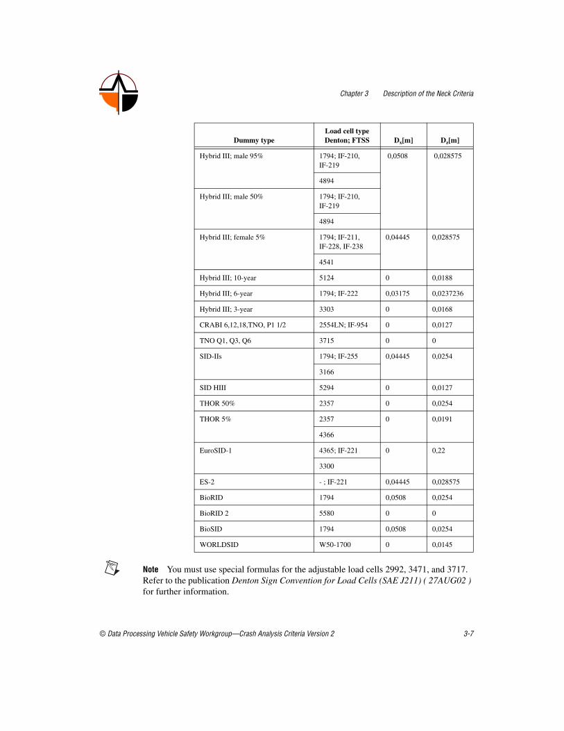
The following table lists the lever arms Dx and Dz in the Lower Load Cell for the calculation in accordance with SAE J1733 in relation to the dummy type.
with MTOi Moment in i-direction [Nm]
Fi Neck force in i-direction [N]
Mi Neck moment in i-direction [Nm]
D Distance between the force sensor axis and the Condyle axis
Chapter 3 Description of the Neck Criteria
© Data Processing Vehicle Safety Workgroup—Crash Analysis Criteria Version 2 3-7
Note You must use special formulas for the adjustable load cells 2992, 3471, and 3717. Refer to the publication Denton Sign Convention for Load Cells (SAE J211) ( 27AUG02 ) for further information.
Dummy typeLoad cell type Denton; FTSS Dx[m] Dz[m]
Hybrid III; male 95% 1794; IF-210, IF-219
0,0508 0,028575
4894
Hybrid III; male 50% 1794; IF-210, IF-219
4894
Hybrid III; female 5% 1794; IF-211, IF-228, IF-238
0,04445 0,028575
4541
Hybrid III; 10-year 5124 0 0,0188
Hybrid III; 6-year 1794; IF-222 0,03175 0,0237236
Hybrid III; 3-year 3303 0 0,0168
CRABI 6,12,18,TNO, P1 1/2 2554LN; IF-954 0 0,0127
TNO Q1, Q3, Q6 3715 0 0
SID-IIs 1794; IF-255 0,04445 0,0254
3166
SID HIII 5294 0 0,0127
THOR 50% 2357 0 0,0254
THOR 5% 2357 0 0,0191
4366
EuroSID-1 4365; IF-221 0 0,22
3300
ES-2 - ; IF-221 0,04445 0,028575
BioRID 1794 0,0508 0,0254
BioRID 2 5580 0 0
BioSID 1794 0,0508 0,0254
WORLDSID W50-1700 0 0,0145

Chapter 3 Description of the Neck Criteria
3-8 ©Data Processing Vehicle Safety Workgroup—Crash Analysis Criteria Version 2
Note Lower Neck Load Cell of BioRID; 1794, validated in dynamic testing LNL .
ISO TS 13499 CodeThe ISO code for the MTO has the following structure.
Output Channel(s)
The following table describes the MTO code.
The following table lists the additional channel header attributes for the MTO.
? ? TMON LO PO ?? MO X X X X
NE Y B
Z
Part of Code Code Description
Test object ? Test object depending
Position ? Position depending
Main location TMON Total Moment Neck
Fine location 1 LO LO = Lower position
Fine location 2 PO; NE PO = positive (Flexion) NE = negative (Extension)
Fine location3 ?? Dummy type dependent
Physical dimension MO Moment
Direction X; Y; Z X = Longitudinal Y = Lateral Z = Vertical
Filter class X; B X = for withoutB = CFC 600 (if stored as Channel)
Attribute Description
.Time The appropriate time where the calculated value occurred.
.Analysis start time Start of the time interval that has been taken into account for the calculation of the value.

Chapter 3 Description of the Neck Criteria
© Data Processing Vehicle Safety Workgroup—Crash Analysis Criteria Version 2 3-9
Input Channel(s)? ? NECK LO 00 ?? MO X B : Lower Neck Moment X, CFC 600? ? NECK LO 00 ?? MO Y B : Lower Neck Moment Y, CFC 600? ? NECK LO 00 ?? MO Z B : Lower Neck Moment Z, CFC 600? ? NECK LO 00 ?? FO X B : Lower Neck Force X, CFC 600? ? NECK LO 00 ?? FO Y B : Lower Neck Force Y, CFC 600? ? NECK LO 00 ?? FO Z B : Lower Neck Force Z, CFC 600
Example Codes1 1 TMON LO PO H3 MO X X : Total Moment Neck X Positive1 1 TMON LO NE H3 MO X X : Total Moment Neck X Negative1 3 TMON LO PO H3 MO Y X : Total Moment Neck Y Positive1 3 TMON LO NE H3 MO Z X : Total Moment Neck Z Negative
Relevant Laws and Regulations• SAE J1727,3.3 (08/96)
• SAE J1733 (12/94)
• Denton Sign Convention for Load Cells (SAE J211) ( 27AUG02 )
.Analysis end time End of the time interval that has been taken into account for the calculation of the value.
.Channel 001
...
.Channel nnn
ISO Code of the first channel used for the calculation. Order of the channels used is arbitrary. Filtering of the channel should be indicated by the right filter class in ISO code at position 16.
.Filter Filter used: Only if all channels has been filtered with the same channel class! This is redundant to the information given in the ISO codes of each channel but easy to observe in the file.
.Dx Distance X between force sensor and joint axis
.Dz Distance Z between force sensor and joint axis
Attribute Description

Chapter 3 Description of the Neck Criteria
3-10 ©Data Processing Vehicle Safety Workgroup—Crash Analysis Criteria Version 2
Time at Level Time-Dependent Loading Criteria
DescriptionThe time-at-level describes the maximum time interval for which the measurement value of a signal has exceeded a specific lower threshold. The value is determined either from the continuous time interval (continuous calculation) or from the sum of all time intervals (cumulative calculation).
Mathematical Calculation
Continuous Calculation (SAE)To determine the relationship between the measured value of the signal (for example the force) and its corresponding time-at-level, the time-related ”load criterion curve” is determined, as the following figure shows.
1. The threshold values are plotted on the ordinate, the times-at-level are plotted on the abscissa.
2. The maximum measured value and the time-at-level zero are assigned to the highest threshold value.
3. In a matrix with two columns and 101 rows, all the threshold values are stored in the first column, starting with the maximum value. All the threshold values in this column are equal to the preceding ones minus the quotient, which is the maximum value divided by 100. Zero is assigned to the threshold value in the last row.
4. The largest continuous time interval in which the threshold value is exceeded by the measurement signal is determined for every threshold

Chapter 3 Description of the Neck Criteria
© Data Processing Vehicle Safety Workgroup—Crash Analysis Criteria Version 2 3-11
value in the first column. Use linear interpolation to determine the time interval, round it to the nearest millisecond, and enter it in the second column.
5. Every line in this matrix describes a value pair (point) that consists of the threshold value and the time at level – the ”load criterion curve” – which are plotted in a coordinate system (criterion graph) and thus compared to the injury assessment boundary. Times at level are only used if they are less than 60 ms.
6. To compare the ”load criterion curve” to the injury assessment boundary, the ratio between the load criterion value and the injury assessment boundary value is determined for each value pair and multiplied by 100. The highest value is the ”injury assessment reference” value which is entered in the coordinate system.
Cumulative Calculation (EuroNCAP)If the sampling rates are constant, the accumulated values can be calculated with the following algorithm:
1. Values in descending order
2. Value (sorted) after x ms is the y-value.
Determining Input Values—
Relevant Laws and Regulations• SAE J1727, 3.9
• EuroNCAP, Front Impact, 10.2.2

Chapter 3 Description of the Neck Criteria
3-12 ©Data Processing Vehicle Safety Workgroup—Crash Analysis Criteria Version 2
NIC (Front Impact ECE)NIC is the abbreviation for Neck Injury Criterion.
DescriptionThe criteria for neck injuries on the hybrid III 50% dummy are determined by the axial compression force, the axial tensile force, and the shearing forces at the transition from head to neck, expressed in kN, and the duration of these forces in ms. The following figure shows these forces.
Mathematical CalculationFor all the above-mentioned signals, the time-at-level is calculated and compared to the limit values. (See also ).
Determining Input ValuesThe measurement values of the axial force Fz and the side shear force Fx are filtered according to CFC 1000. (See also ).

Chapter 3 Description of the Neck Criteria
© Data Processing Vehicle Safety Workgroup—Crash Analysis Criteria Version 2 3-13
ISO TS 13499 CodeThe ISO code for the NIC (front impact ECE) has the following structure.
Output Channel(s)
The following table describes the NIC (front impact ECE) code.
The following table lists the additional channel header attributes for the NIC (front impact ECE).
? ? NICF SP DP ?? 00 X X
ZU DN Z
DU
Part of Code Code Description
Test object ? Test object depending
Position ? Position depending
Main location NICF Neck Injury Criterion, Front
Fine location 1 SP; CU SP = Single Peak CU = Cumulative
Fine location 2 DP; DN; DU DP = Duration of loading positive DN = Duration of loading negativeDU = Duration of loading
Fine location3 ?? Dummy type dependent
Physical dimension 00 Without
Direction X; Z X(+) = Shear forceZ(+) = Tensile ForceZ(-) = Compression Force
Filter class X Without
Attribute Description
.Duration time For load-duration calculations: Duration for the value closest to the limit line
.Analysis start time Start of the time interval that has been taken into account for the calculation of the value.

Chapter 3 Description of the Neck Criteria
3-14 ©Data Processing Vehicle Safety Workgroup—Crash Analysis Criteria Version 2
Input Channel(s)? ? NECK UP 00 ?? FO X A : (+)pos. Upper Neck Force X,
CFC 1000? ? NECK UP 00 ?? FO Z A : Upper Neck Force Z, CFC 1000
Example Codes1 1 NICF SP DU H3 00 X X : NIC Load Duration X Single Peak1 1 NICF CU DU H3 00 Z X : NIC Load Duration Z Cummulative1 1 NICF SP DP H3 00 X X : NIC Load Duration X Pos. Single
Peak1 1 NICF CU DP H3 00 Z X : NIC Load Duration Z Pos.
Cummulative1 1 NICF SP DN H3 00 X X : NIC Load Duration X Neg. Single
Peak1 1 NICF CU DN H3 00 Z X : NIC Load Duration Z Pos.
Cummulative
Relevant Laws and Regulations• Richtlinie 96/79/EG, Anhang II, 3.2.1.2
• Richtlinie 96/79/EG, Anhang II, Anlage 2, 2
• ECE-R94, 5.2.1.2
• ECE-R94, Anhang 4, 2
• SAE J1733
.Analysis end time End of the time interval that has been taken into account for the calculation of the value.
.Absolute value For load-duration calculations: Absolute value for the value closest to the limit line.
.Channel 001 ISO Code of the first channel used for the calculation. Order of the channels used is arbitrary. Filtering of the channel should be indicated by the right filter class in ISO code at position 16.
.Filter Filter used: Only if all channels has been filtered with the same channel class! This is redundant to the information given in the ISO codes of each channel but easy to observe in the file.
Attribute Description

Chapter 3 Description of the Neck Criteria
© Data Processing Vehicle Safety Workgroup—Crash Analysis Criteria Version 2 3-15
NIC (Front Impact EuroNCAP)NIC is the abbreviation for Neck Injury Criterion.
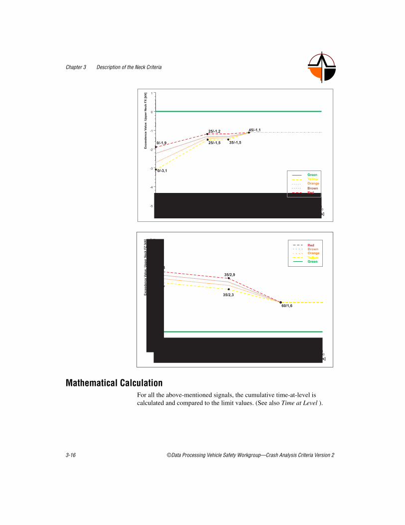
DescriptionThe criteria for neck injuries are determined by the axial tensile force Fz(+), and the shearing forces at the transition from head to neck, expressed in kN, and the duration of these forces in ms. The following figures illustrate these forces.
Note The dotted lines are determined from the Lower Limit and Upper Limit by linear scaling.
Chapter 3 Description of the Neck Criteria
3-16 ©Data Processing Vehicle Safety Workgroup—Crash Analysis Criteria Version 2
Mathematical CalculationFor all the above-mentioned signals, the cumulative time-at-level is calculated and compared to the limit values. (See also Time at Level ).

Chapter 3 Description of the Neck Criteria
© Data Processing Vehicle Safety Workgroup—Crash Analysis Criteria Version 2 3-17
Determining Input ValuesThe measurement values of the axial force Fz and the side shear force Fx are filtered according to CFC 1000. (See also CFC Filters).
ISO TS 13499 CodeThe ISO code for the NIC (front impact EuroNCAP) has the following structure.
Output Channel(s)
The following table describes the NIC (front impact EuroNCAP) code.
The following table lists the additional channel header attributes for the NIC (front impact EuroNCAP).
? ? NIEF CU DP ?? 00 X X
DN Z
Part of Code Code Description
Test object ? Test object depending
Position ? Position depending
Main location NIEF Neck Injury Criterion, Front
Fine location 1 CU CU = Cumulative
Fine location 2 DP; DN DP = Duration of loading positive DN = Duration of loading negative
Fine location3 ?? Dummy type dependent
Physical dimension 00 Without
Direction X; Z X = Shear forceZ(+) = Tensile ForceZ(-) = Compression Force
Filter class X Without

Chapter 3 Description of the Neck Criteria
3-18 ©Data Processing Vehicle Safety Workgroup—Crash Analysis Criteria Version 2
Input Channel(s)? ? NECK UP 00 ?? FO X A : Upper Neck Force X, CFC 1000? ? NECK UP 00 ?? FO Z A : Upper Neck Force Z, CFC 1000
Example Codes1 1 NIEF CU DP H3 00 X X : Neck Injury Criterion, EuroNCAP1 1 NIEF CU DN H3 00 X X : Neck Injury Criterion, EuroNCAP1 1 NIEF CU DP H3 00 Z X : Neck Injury Criterion, EuroNCAP
Relevant Laws and Regulations• EuroNCAP, Frontal Impact, 10.2
• SAE J1733
• EuroNCAP, Assessment Protocol and Biomechanical Limits
Attribute Description
.Duration time For load-duration calculations: Duration for the value closest to the limit line
.Analysis start time Start of the time interval that has been taken into account for the calculation of the value.
.Analysis end time End of the time interval that has been taken into account for the calculation of the value.
.Absolute value For load-duration calculations: Absolute value for the value closest to the limit line.
.Channel 001 ISO Code of the first channel used for the calculation. Order of the channels used is arbitrary. Filtering of the channel should be indicated by the right filter class in ISO code at position 16.
.Filter Filter used: Only if all channels has been filtered with the same channel class! This is redundant to the information given in the ISO codes of each channel but easy to observe in the file.
.ENCAP Points .EuroNCAP Points

Chapter 3 Description of the Neck Criteria
© Data Processing Vehicle Safety Workgroup—Crash Analysis Criteria Version 2 3-19
NIC (Front Impact FMVSS)NIC is the abbreviation for Neck Injury Criterion.
DescriptionNIC is the criterion for neck injury. The (a) Normalized Neck Injury Criterion (Nij) and the (b) Peak tension and Peak compression are elements of the NIC.
Mathematical Calculation1. See also Nij
2. See also NIJ
3. The following table shows the limit values for each dummy type.
Determining Input ValuesThe measurement values of the limit value monitoring are filtered in accordance with CFC 600. (See also CFC Filters).
ISO TS 13499 CodeThe ISO code for the NIC (front impact FMVSS) has the following structure.
Output Channel(s)
Position Dummy TypeFz [N] Peak
TensionFz [N] Peak
Compression
In position Hybrid III; male 50% 4170 -4000
Hybrid III; female 5% 2620 -2520
Hybrid III; 6-year 1490 -1820
Hybrid III; 3-year 1130 -1380
CRABI; 12 months 780 -960
Out of position Hybrid III; female 5% 2070 -2520
? ? NECK IP TN ?? FO Z X
OP CO

Chapter 3 Description of the Neck Criteria
3-20 ©Data Processing Vehicle Safety Workgroup—Crash Analysis Criteria Version 2
The following table describes the NIC (front impact FMVSS) code.
The following table lists the additional channel header attributes for the NIC (front impact FMVSS).
Input Channel(s)? ? NECK UP 00 ?? FO Z B : Upper Neck Force Z, CFC 600? ? NECK UP 00 ?? MO Y A : Upper Neck Force Y, CFC 600
Part of Code Code Description
Test object ? Test object depending
Position ? Position depending
Main location NECK Neck
Fine location 1 IP; OP IP = in position OP = out of position
Fine location 2 TN; CO TN = Tension CO = Compression
Fine location3 ?? Dummy type dependent
Physical dimension FO Force
Direction Z Z(+) = Tensile ForceZ(-) = Compression Force
Filter class X Without
Attribute Description
.Time The appropriate time where the calculated value occurred.
.Analysis start time Start of the time interval that has been taken into account for the calculation of the value.
.Analysis end time End of the time interval that has been taken into account for the calculation of the value.
.Channel 001 ISO Code of the first channel used for the calculation. Order of the channels used is arbitrary. Filtering of the channel should be indicated by the right filter class in ISO code at position 16.
.Filter Filter used: Only if all channels has been filtered with the same channel class! This is redundant to the information given in the ISO codes of each channel but easy to observe in the file.

Chapter 3 Description of the Neck Criteria
© Data Processing Vehicle Safety Workgroup—Crash Analysis Criteria Version 2 3-21
Example Codes1 1 NECK IP CO H3 FO Z X : Neck In Position Compression
Force Z1 3 NECK IP TN H3 FO Z X : Neck In Position Tensile Force Z1 1 NECK OP CO H3 FO Z X : Neck Out Of Position Compression
Force Z1 3 NECK OP TN H3 FO Z X : Neck Out Of Position Tensile
Force Z
Relevant Laws and Regulations• FMVSS 208 (Mai 2000), S6.6 (b)(c); (HyIII-50%)
• FMVSS 208 (Mai 2000), S15.3.6 (b)(c); (HyIII-5%)
• FMVSS 208 (Mai 2000), S19.4.4 (b)(c); (HyIII-12M)
• FMVSS 208 (Mai 2000), S21.5.5 (b)(c); (HyIII-3-year)
• FMVSS 208 (Mai 2000), S23.5.5 (b)(c); (HyIII-6-year)
• FMVSS 208 (Mai 2000), S25.4 (b)(c); (HyIII-5% Out of position)

Chapter 3 Description of the Neck Criteria
3-22 ©Data Processing Vehicle Safety Workgroup—Crash Analysis Criteria Version 2
NIJNij is the abbreviation for Normalized Neck Injury Criterion and is the 4 neck criterion (Neck Injury Predictor) NTE (tension-extension), NTF (tension-flexion), NCE (compression-extension), NCF (compression-flexion).
DescriptionThe criteria for neck injuries are determined using the axial compression force, the axial tensile force, and the shearing forces at the transition from head to neck, expressed in kN, and the duration of these forces in ms. The neck bending moment criterion is determined by the bending moment, expressed in Nm, around a lateral axis at the transition from the head to the neck, and recorded.
Mathematical CalculationThe Nij value is calculated with the following formula:
Determining Input ValuesThe measured values of the tensile force and compression force are filtered in accordance with CFC 600. (See also CFC Filters). The Total Moment is calculated in accordance with MOC.
When the criteria are calculated, particular forces and moments are to be set at 0. This is an AND condition, that is if one of the summands is zero, the condition is also zero. The following table lists the dependencies between forces and moments.
with Fz Force at the point of transition from head to neck.
Fzc Critical force
MOCy Total Moment (see also MOC)
Myc Critical moment

Chapter 3 Description of the Neck Criteria
© Data Processing Vehicle Safety Workgroup—Crash Analysis Criteria Version 2 3-23
The following table specifies the critical forces F zc and moments M yc for the ‘in position test‘ according to the dummy types.
*The negative signs for Fzc and Myc give positive Nij values (signal polarity in accordance with SAE J211 and SAE J1733).
The following table specifies the critical forces Fzc and moments Myc for the ‘in position test‘ according to the dummy types.
*The negative signs for Fzc and Myc give positive Nij values (signal polarity in accordance with SAE J211 and SAE J1733).
Criterion Nij Forces Moments
NCF Compression (compression force) F<0
Flexion (forwards bending) M>0
NCE Extension (backwards extension) M<0
NTF Tension (tensile force) F>0 Flexion (forwards bending) M>0
NTE Extension (backwards extension) M<0
Dummy TypeFzc [N] Tension
Fzc [N]* Compression
Myc [Nm] Flexion
Myc [Nm]* Extension
Hybrid III; male 50% 6806 -6160 310 -135
Hybrid III; female 5% 4287 - 3880 155 - 67
class="Bordered">Dummy Type
Fzc [N] Tension
Fzc [N]* Compression
Myc [Nm] Flexion
Myc [Nm]* Extension
Hybrid III; female 5% 3880 -3880 155 -61
Hybrid III; 6-year 2800 -2800 93 -37
Hybrid III; 3-year 2120 -2120 68 -27
Hybrid III; 12 months 1460 -1460 43 -17

Chapter 3 Description of the Neck Criteria
3-24 ©Data Processing Vehicle Safety Workgroup—Crash Analysis Criteria Version 2
ISO TS 13499 CodeThe ISO code for the NIJ has the following structure.
Output Channel(s)
The following table describes the NIJ code.
The following table lists the additional channel header attributes for the NIJ.
? ? NIJC IP CE ?? 00 X X
OP CF Y B
TE
TF
00
Part of Code Code Description
Test object ? Test object depending
Position ? Position depending
Main location NIJC Normalized Neck Injury Criterion
Fine location 1 IP; OP IP = in position OP = out of position
Fine location 2 CE;CF;TE;TF; 00
CE = Compression and Extension CF = Compression and FlexionTE = Tension and ExtensionTF = Tension and Flexion00 = absolute maximum of CE;CF;TE;TF (optional)
Fine location3 ?? Dummy type dependent
Physical dimension 00 Without
Direction X; Y X = Longitudinal (Side Impact)Y = Lateral (Frontal Impact)
Filter class X; B X = for withoutB = CFC 600 (if stored as Channel)

Chapter 3 Description of the Neck Criteria
© Data Processing Vehicle Safety Workgroup—Crash Analysis Criteria Version 2 3-25
Input Channel(s)? ? NECK UP 00 ?? FO Z B : Upper Neck Force Z, CFC 600? ? NECK UP 00 ?? MO Y B : Upper Neck Moment Y, CFC 600
Example Codes1 1 NIJC IP CE H3 00 Y X : Neck Injury Criterion Comp./Exte.1 3 NIJC OP CF Y6 00 Y X : Neck Injury Criterion Comp./Flex.1 1 NIJC OP TE HF 00 Y X : Neck Injury Criterion Tens./Exte.1 1 NIJC OP TF H3 00 Y X : Neck Injury Criterion Tens./Flex.
Relevant Laws and Regulations• FMVSS 208 (May 2000), S6.6
• FMVSS 208 (May 2000), S15.3.6
• FMVSS 208 (May 2000), S19.4.4
• FMVSS 208 (May 2000), S21.5.5
• FMVSS 208 (May 2000), S23.5.5
Attribute Description
.Time The appropriate time where the calculated value occurred.
.Analysis start time Start of the time interval that has been taken into account for the calculation of the value.
.Analysis end time End of the time interval that has been taken into account for the calculation of the value.
.Channel 001
...
.Channel nnn
ISO Code of the first channel used for the calculation. Order of the channels used is arbitrary. Filtering of the channel should be indicated by the right filter class in ISO code at position 16.
.Filter Filter used: Only if all channels has been filtered with the same channel class! This is redundant to the information given in the ISO codes of each channel but easy to observe in the file.
.Fzcc Critical compression force
.Fzct Critical tension force
.Mycf Critical flexion moment
.Myce Critical extension moment
Chapter 3 Description of the Neck Criteria
3-26 ©Data Processing Vehicle Safety Workgroup—Crash Analysis Criteria Version 2
Publications:• Supplement: Development of Improved Injury Criteria for the
Assessment of Advanced Automotive Retraint Systems-II; Rolf Eppinger, Emily Sun, Shashi Kuppa (NTBRC) and Roger Saul (VRTC); March 2000 NHTSA

Chapter 3 Description of the Neck Criteria
© Data Processing Vehicle Safety Workgroup—Crash Analysis Criteria Version 2 3-27
NIC (Rear Impact)NIC is the abbreviation for Neck Injury Criterion.
DescriptionThe criterion for the neck injury with a rear impact is expressed by the relative acceleration between the upper and lower neck acceleration, in m/s², and the relative velocity, in m/s.
Mathematical CalculationThe NIC value is calculated with the following formula:
with:
Determining Input ValuesThe measurement values of the accelerations are filtered in accordance with CFC 180. (See also CFC Filters). The NICmax value specifies and documents the maximum value of the NIC within an interval of 150 ms after the start of the sled acceleration. If the head changes the direction of the relative movement at a time point within the 150 ms interval after contact with the head rest, this time point limits the NIC interval for determining the NIC max value.
and axT1 Acceleration in X direction of the first thorax
spine in [m/s2]
axHead Acceleration in x-direction measured at the
height of the c.o.g. of the head [m/s2]

Chapter 3 Description of the Neck Criteria
3-28 ©Data Processing Vehicle Safety Workgroup—Crash Analysis Criteria Version 2
ISO TS 13499 CodeThe ISO code for the NIC (rear impact) has the following structure.
Output Channel(s)
The following table describes the NIC (rear impact) code.
The following table lists the additional channel header attributes for the NIC (rear impact).
? ? NICR ?? SI ?? 00 X X
FI
Part of Code Code Description
Test object ? Test object depending
Position ? Position depending
Main location NICR NIC Rear Impact Criterion
Fine location 1 ?? Fine location 1 dependent
Fine location 2 SI; FI SI = selected interval, according to video analysisFI = fixed interval (0...150ms)
Fine location3 ?? Dummy type dependent
Physical dimension 00 Without
Direction X X = Longitudinal
Filter class X Without
Attribute Description
.Time The appropriate time where the calculated value occurred.
.Analysis start time Start of the time interval that has been taken into account for the calculation of the value.
.Analysis end time End of the time interval that has been taken into account for the calculation of the value.
.Factor Factor used in the calculation: currently for NICR

Chapter 3 Description of the Neck Criteria
© Data Processing Vehicle Safety Workgroup—Crash Analysis Criteria Version 2 3-29
Input Channel(s)? ? HEAD 00 00 ?? AC X C : Head Acceleration X, CFC 180? ? SPIN 01 00 ?? AC X C : Spine Acceleration X, CFC 180
Example Codes1 1 NICR 00 FI BR 00 X X : NIC Rear Impact selected interval1 3 NICR 00 SI BR 00 X X : NIC Rear Impact fixed interval
Relevant Laws and RegulationsThis injury criterion is in the research phase.
Publications:• A SLED TESTS PROCEDURE PROPOSAL TO EVALUATE THE
RISK OF NECK INJURY IN LOW SPEED REAR IMPACTS USING A NEW NECK INJURY CRITERION (NIC); Paper no. 98-S7-O-07; Ola Boström, Yngve Håland, Rikard Frediksson, Autoliv Research Sweden, Mats Y Svensoson Hugo Mellander, Chalmers University of Technology Sweden; 16 th ESV Conference; June 1-4, 1998 Windsor Canada
• EVALUATION OF THE APPLACABILITY OF THE NECK INJURY CRITERION (NIC) IN REAR END IMPACTS ON THE BASIS OF HUMAN SUBJECT TESTS; A.Eichberger, H. Steffan, B.Geigl, M.Svensson, O. Boström, P.E. Leinzinger, M.Darok; IRCOBI Conference – Göteborg, September 1998
• Proposal for the ISO/TC22N2071, ISO/TC22/SC10 (Collision Test Procedures): TEST PROCEDURE FOR THE EVALUATION OF THE INJURY RISK TO THE CERVICAL SPINE IN A LOW SPEED REAR END IMPACT; M. Muser, H. Zellmer, F. Walz, W. Hell, K. Langwieder, K. Steiner, H. Steffan; Rear end impact test procedure, working draft 5, 05/2001
.Channel 001 ... .Channel nnn
ISO Code of the first channel used for the calculation. Order of the channels used is arbitrary. Filtering of the channel should be indicated by the right filter class in ISO code at position 16.
.Filter Filter used: Only if all channels has been filtered with the same channel class! This is redundant to the information given in the ISO codes of each channel but easy to observe in the file.
Attribute Description

Chapter 3 Description of the Neck Criteria
3-30 ©Data Processing Vehicle Safety Workgroup—Crash Analysis Criteria Version 2
NkmNkm corresponds to the 4 neck criteria Nfa (flexion-anterior), Nea (extension-anterior), Nfp (flexion-posterior), and Nep (extension-posterior).
DescriptionThe criteria for neck injuries for the rear impact (see also MOC) are calculated by adding the standardized shear forces and the standardized corrected bending moment.
Mathematical CalculationThe Nkm value is calculated with the following formula:
Determining Input ValuesThe measured values of the tension are filtered in accordance with CFC 600. The measured values of the bending moment and the side shearing force are also filtered in accordance with CFC 600. (See also CFC Filters.
When the criteria are calculated, particular forces and moments must be set to 0. This is an AND condition, that is if one of the summands is zero, the condition is also zero. The following table lists the dependencies between forces and moments.
with Fx Force at the point of transition from head to neck.
Fint Head acceleration in the i direction
Fi Critical force
MOCy Total Moment (see also MOC)
Mint Critical moment

Chapter 3 Description of the Neck Criteria
© Data Processing Vehicle Safety Workgroup—Crash Analysis Criteria Version 2 3-31
The following table lists the critical forces Fint and moments Mint for the hybrid III dummy type; male 50%.
*The negative signs of Fint and Mint make positive Nkm values (signal polarity in accordance with SAE J211 and SAE J1733).
Relevant Laws and Regulations• Working Group for Accident Mechanics www.agu.ch
Publications• A NEW NECK INJURY CRITERION CANDIDATE FOR
REAR-END COLLISIONS TAKING INTO ACCOUNT SHEAR FORCES AND BENDING MOMENTS (Schmitt, Muser, Niederer) ESV Conference 2001, Amsterdam NL
Criterion Nkm Forces Moments
Nfa anterior (head backwards, torso forwards) Fx>0
Flexion (forwards bending) My>0
Nea Extension (backwards extension) My<0
Nfp posterior (head forwards, torso backwards) Fx>0
Flexion (forwards bending) My>0
Nep Extension (backwards extension) My<0
Moment Force
Positive Shear Fint 845 N
Negative Shear* Fint -845 N
Flexion Mint 88,1 Nm
Extension* Mint -47,5 Nm

Chapter 3 Description of the Neck Criteria
3-32 ©Data Processing Vehicle Safety Workgroup—Crash Analysis Criteria Version 2
LNL LNL is the abbreviation for the Lower Neck Load Index.
DescriptionThe risk of damaging the lower neck vertebrae in a rear-impact crash is highest when the forces and moments impact simultaneously.
Mathematical CalculationThe LNL value is calculated with the following formula:
Note The formula is valid for the Lower Neck Load Cell of the RID2 and Hybrid III.
• The result My can be corrected for the Hybrid III with the Denton 1794, FMVSS IF-210, and IF-219, MSC 4894 power cells, with the following formula.
• The My moment must not be corrected for RID2.
with Mylower Moment in y-direction
Mxlower Moment in x-direction
Cmoment Critical moment
Fxlower Force in x-direction
Fylower Force in y-direction
Cshear Critical force
Fzlower Force in z-direction
Ctension Critical force

Chapter 3 Description of the Neck Criteria
© Data Processing Vehicle Safety Workgroup—Crash Analysis Criteria Version 2 3-33
Determining Input ValuesThe measurement values of the forces and the moments are filtered in accordance with CFC 600. (See also CFC Filters). This filtering is valid regardless of the filter classes defined in SAEJ211. (Compare FMVSS208 with reference to Legislation and Directives NIJNIJ).
The following table lists the critical forces and moments for the dummy type RID2.
Relevant Laws and Regulations• SAE J1727
• SAE J1733
• Denton Sign Convention for Load Cells
• AN EVALUATION OF EXISTING AND PROPOSED INJURY CRITERIA WITH VARIOUS DUMMIES TO DETERMINE THEIR ABILITY TO PREDICT THE LEVELS OF SOFT TISSUE NECK INJURY SEEN IN REAL WORLD ACCIDENTS; Frank Heitplatz et all; ESV Conference 2003
Moment Force
Cmoment 15 [Nm]
Cshear 250 [N]
Ctension 900 [N]

© Data Processing Vehicle Safety Workgroup—Crash Analysis Criteria Version 2 4-1
4Description of the chest criteria
The following chest criteria are described:
• VC — Viscous Criterion (velocity of compression)
• THPC — Thorax Performance Criterion
• TTI(d) — Thoracic Trauma Index (Thorax Trauma Index)
• ThAC — Thorax Acceptability Criterion
• CTI — Combined Thoracic Index
• ThCC or TCC — Thoracic Compression Criterion
• RDC — Rib Deflection Criterion
• CDR (TWG) — Chest Deflection (Compression) Rate

Chapter 4 Description of the chest criteria
4-2 ©Data Processing Vehicle Safety Workgroup—Crash Analysis Criteria Version 2
VCVC is the abbreviation for Viscous Criterion (velocity of compression), and is also called the Soft Tissue Criterion.
DescriptionVC is an injury criterion for the chest area. The VC value [m/s] is the maximum crush of the momentary product of the thorax deformation speed and the thorax deformation. Both quantities are determined by measuring the rib deflection (side impact) or the chest deflection (frontal impact).
Note Only the crush is included in the calculation.
Mathematical CalculationThe following formulas calculate the VC value:
In accordance with ECE-R94, ECE-R95 and EuroNCAP (front and side impact)
In accordance with SAE J1727: (Frontal impact)
with Y Thoracic deformation [m]
dYCFCxxx/dt Deformation velocity
Scaling factor Scaling factor (see also Determining Input Values)
Def. const. Dummy constant, that is depth or width of half the rib cage [mm] (see also Determining Input Values)

Chapter 4 Description of the chest criteria
© Data Processing Vehicle Safety Workgroup—Crash Analysis Criteria Version 2 4-3
The deformation speed is calculated in accordance with ECE R94:f_vc_3.gif@
Note If required, the chest or rib crush/velocity can be calculated with the difference between opposite acceleration signals, using integration. This method is not included in any of the listed laws or guidelines.
Determining Input ValuesRefer to the mathematical calculation for details on filtering input values.
The following table contains the scaling factor and the deformation constant (dummy constants) for each dummy type, in accordance with SAE J1727, 8/96.
with Δt Time interval between the single measurements in seconds
Dummy type Scaling factorDeformation constant
[mm]
Hybrid III; male 95% 1,3 254
Hybrid III; male 50% 1,3 229
Hybrid III; female 5% 1,3 187
BioSID 1,0 175
EuroSID-1 1,0 140
ES-2 1,0 140
SID-IIs 1,0 138

Chapter 4 Description of the chest criteria
4-4 ©Data Processing Vehicle Safety Workgroup—Crash Analysis Criteria Version 2
ISO TS 13499 CodeThe ISO code for the VC is structured as follows.
Output Channel(s)
The following table describes the VC code.
? ? VCCR 00 00 ?? VE X X
VCAR UP 01 Y B
LO 02 C
RI 03
LE UP
MI
LO
Part of Code Code Description
Test object ? Test object depending
Position ? Position depending
Main location VCCR; VCAR VCCR = Viscous Criterion, (Thoracic Ribs)VCAR = Viscous Criterion, (Abdominal Ribs)
Fine location 1 00; LO; UP; LE; RI
00 = Not Definied (for V*C calculation of frontal impact dummy like H3 based on rotational potentiometer)LO = Lower PositionUP = Upper Position (determine V*C from acceleration measurement on the sternum and spine)LE = Left PositionRI = Right Position (for side impact dummies)

Chapter 4 Description of the chest criteria
© Data Processing Vehicle Safety Workgroup—Crash Analysis Criteria Version 2 4-5
The following table lists the additional channel header attributes for the VC.
Fine location 2 00; 01; 02; 03; UP; MI; LO
00 = Not DefiniedUP = UpperMI = MiddleLO = Lower (Use 01, 02, 03 or UP, MI, LO according to the coding for the related channel of a side impact dummy (dummy specific). Regardless of the coding for the dummy in FL1 and FL2 here is a strict rule to have LE and RI in FL1 and then UP, MI, LO or 01, 02, 03 in FL2!)
Fine location3 ?? Dummy type dependent
Physical dimension VE VE = Velocity
Direction X; Y X = LongitudinalY = Lateral (Side)
Filter class X; B; C X = WithoutB = CFC 600 (if stored as channel)C = CFC 180 (if stored as channel)
Attribute Description
.Time The appropriate time where the calculated value occurred.
.Analysis start time Start of the time interval that has been taken into account for the calculation of the value.
.Analysis end time End of the time interval that has been taken into account for the calculation of the value.
.Factor Factor used in the calculation: currently for NICR
.Channel 001
...
.Channel nnn
ISO Code of the first channel used for the calculation. Order of the channels used is arbitrary. Filtering of the channel should be indicated by the right filter class in ISO code at position 16.
.Filter Filter used: Only if all channels has been filtered with the same channel class! This is redundant to the information given in the ISO codes of each channel but easy to observe in the file.
Part of Code Code Description

Chapter 4 Description of the chest criteria
4-6 ©Data Processing Vehicle Safety Workgroup—Crash Analysis Criteria Version 2
Input Channel(s)? ? CHST ?? 00 ?? DS X B : Frontal Impact DS, Chest
Displacement X, CFC 600? ? SPIN ?? 00 ?? AC X ? : Frontal Impact AC, Spinal
Acceleration X? ? STRN ?? 00 ?? AC X ? : Frontal Impact AC; Sternum
Acceleration X? ? RIBS ?? UP ?? DS Y C : Side Impact DS, Upper Ribs
Displacement Y, CFC 180? ? RIBS ?? MI ?? DS Y C : Side Impact DS, Middle Ribs
Displacement Y, CFC 180? ? RIBS ?? LO ?? DS Y C : Side Impact DS, Lower Ribs
Displacement Y, CFC 180? ? TRRI ?? 01 ?? DS Y C : Side Impact DS, Thorax Rib
Displacement Y, CFC 180? ? TRRI ?? 02 ?? DS Y C : Side Impact DS, Thorax Rib
Displacement Y, CFC 180? ? TRRI ?? 03 ?? DS Y C : Side Impact DS, Thorax Rib
Displacement Y, CFC 180? ? ABRI ?? 01 ?? DS Y C : Side Impact DS, Abdominal Rib
Displacement Y, CFC 180? ? ABRI ?? 02 ?? DS Y C : Side Impact DS, Abdominal Rib
Displacement Y, CFC 180
Example Codes• VCCR (Viscous Criterion)
1 1 VCCR 00 00 H3 VE X X : Viscous Criterion Driver X1 1 VCCR LE UP E2 VE Y X : Viscous Criterion upper left rib Y1 1 VCCR LE MI E2 VE Y X : Viscous Criterion middle left rib Y1 1 VCCR LE LO E2 VE Y X : Viscous Criterion lower left rib Y1 1 VCCR RI 01 S2 VE Y X : Viscous Criterion upper right rib Y1 1 VCCR RI 02 S2 VE Y X : Viscous Criterion middle right rib Y1 1 VCCR RI 03 S2 VE Y X : Viscous Criterion lower right rib Y
.Scaling factor Scaling factor in the V*C formula (could alternatively also be described as "factor"; Scaling factor has been taken from the paper describing crash criteria)
.Deformation constant Deformation constant according to SAE J1727, 8/96
Attribute Description

Chapter 4 Description of the chest criteria
© Data Processing Vehicle Safety Workgroup—Crash Analysis Criteria Version 2 4-7
• VCAR (Viscous Criterion Abdomen Rib)1 1 VCAR LE UP BS VE Y X : Viscous Criterion upper left
abdominal rib Y1 1 VCAR LE LO BS VE Y X : Viscous Criterion lower left
abdominal rib Y1 1 VCAR RI 01 S2 VE Y X : Viscous Criterion upper right
abdominal rib Y1 1 VCAR RI 02 S2 VE Y X : Viscous Criterion lower right
abdominal rib Y
Relevant Laws and Regulations• ECE R94, Directive 96/79/EG, Annex II, 3.2.1.5
• ECE R94, Directive 96/79/EG, Annex II, Appendix 2, 6.1-6.2
• ECE-R94, 5.2.1.4
• ECE R94, Annex 4, 3.2
• ECE R94, Annex 4, 6
• ECE R95, 5.2.1.2 b)
• ECE R95, Annex 4, Appendix 1, 2.2
• ECE R95, Annex 4, Appendix 2
• Directive 96/27 EG Annex 2, 3.2.1.2 b)
• Directive 96/27 EG Annex 1, Appendix 1, 2.2
• Directive 96/27 EG Annex 1, Appendix 2
• SAE J211, 9.4.3
• SAE J1727, 3.8.1
• EuroNCAP, Front Impact, 10.3
• EuroNCAP, Side Impact, 10.3

Chapter 4 Description of the chest criteria
4-8 ©Data Processing Vehicle Safety Workgroup—Crash Analysis Criteria Version 2
THPCTHPC is the abbreviation for Thorax Performance Criterion
DescriptionTHPC is the criterion for chest strain with side impact. The two elements of the THPC are the rib deflection criterion (RDC) and the viscous criterion (VC).
Mathematical CalculationSee also RDC and VC.
Determining Input ValuesSee also RDC and VC.
ISO TS 13499 CodeThe ISO code for the THPC is structured as follows.
Output Channel(s)
The following table describes the THPC code.
? ? THPC ?? ?? ?? EV 0 X
Part of Code Code Description
Test object ? Test object depending
Position ? Position depending
Main location THPC Thoracic Performance Criterion
Fine location 1 ?? Fine location 1 dependent
Fine location 2 ?? Fine location 2 dependent
Fine location3 ?? Dummy type dependent
Physical dimension EV EV = Event (just pass/fail information based on other criteria (VC and RDC). Used for side impact (ECE-R95)

Chapter 4 Description of the chest criteria
© Data Processing Vehicle Safety Workgroup—Crash Analysis Criteria Version 2 4-9
Input Channel(s)? ? VCCR ?? ?? ?? VE Y X : Viscous Criterion, Velocity Y? ? RDCR ?? ?? ?? DS Y X : Rib Deflection Criterion,
Displacement Y
Example Codes1 1 THPC 00 00 E1 EV 0 X : Thoracic Performance Criterion
Relevant Laws and Regulations• ECE-R95, 5.2.1.2
• ECE R95, Annex 4, Appendix 1, 2
• Directive 96/27 EG Annex 2, 3.2.1.2
• Directive 96/27 EG Annex 1, Appendix 1, 2
• Directive 96/27 EG Annex 1, Appendix 2
Direction 0 0 = Without
Filter class X X = Without
Part of Code Code Description

Chapter 4 Description of the chest criteria
4-10 ©Data Processing Vehicle Safety Workgroup—Crash Analysis Criteria Version 2
TTI(d) TTI(d) is the abbreviation for Thoracic Trauma Index (Thorax Trauma Index).
DescriptionThe thorax trauma index is an injury criterion for the thorax in the case of a side impact. The TTI(d) is the mean of the lateral maximum acceleration of the abdominal spine (12th spinal segment) and the higher of the two values for the maximum acceleration of the upper (8th) and lower (4th) Rib.
Mathematical CalculationThe TTI value is calculated with the following formula:
Determining Input ValuesPreprocessing the acceleration data of the single sensors (see also CFC Filters):
1. Filtering with CFC 180
2. Reduction of the sampling rate to 1600 Hz
3. Removal of bias
4. Filtering with FIR 100
5. Transferring the reduced sampling rate to the original sampling rate (oversampling, only SAE)
with A(upr.rib) Maximum acceleration of the upper rib; [g]
A(lwr.rib) Maximum acceleration of the lower rib; [g]
A(max.rib) Maximum of A(upr.rib) and A(lwr.rib); [g]
A(lwr.spine) Maximum acceleration of the lower spine; [g]

Chapter 4 Description of the chest criteria
© Data Processing Vehicle Safety Workgroup—Crash Analysis Criteria Version 2 4-11
Due to the sign regulations in SAE J1733, the acceleration values have to be positive absolute maximum values. If test data with negative absolute maximum values are to be evaluated, the measurement data must first be inverted.
The calculation must use the original measurement data, not selected data sections, otherwise the digital filters may have differing transient responses.
ISO TS 13499 CodeThe ISO code for the TTI(d) is structured as follows.
Output Channel(s)
The following table describes the TTI(d) code.
The following table lists the additional channel header attributes for the TTI(d) .
? ? TTIN ?? ?? ?? AC Y X
1
Part of Code Code Description
Test object ? Test object depending
Position ? Position depending
Main location TTIN Thoracic Trauma Index
Fine location 1 ?? Fine location 1 dependent
Fine location 2 ?? Fine location 2 dependent
Fine location3 ?? Dummy type dependent
Physical dimension AC Acceleration
Direction Y Y = Lateral
Filter class X; 1 X = Without1 = FIR100 (if stored as channel)

Chapter 4 Description of the chest criteria
4-12 ©Data Processing Vehicle Safety Workgroup—Crash Analysis Criteria Version 2
Input Channel(s)? ? RIBS ?? UP ?? AC Y C : Upper Ribs Acceleration Y,
CFC 180? ? RIBS ?? LO ?? AC Y C : Lower Ribs Acceleration Y,
CFC 180? ? SPIN 12 ?? SI AC Y C : Spinal Acceleration Y, CFC 180 ? ? SPIN 12 ?? E1 AC Y C : Spinal Acceleration Y, CFC 180
Example Codes1 1 TTIN 00 00 SI AC Y X : Thoracic Trauma Index
Relevant Laws and Regulations• FMVSS 214, S5.1
• FMVSS 214, S6.13.5
• SAE J1727, 3.5
Attribute Description
.Time rib The appropriate time where the calculated value occurred.
.Time spine The appropriate time where the calculated value occurred.
.Analysis start time Start of the time interval that has been taken into account for the calculation of the value.
.Analysis end time End of the time interval that has been taken into account for the calculation of the value.
.Channel 001
.Channel 002ISO Code of the first channel used for the calculation. Order of the channels used is arbitrary. Filtering of the channel should be indicated by the right filter class in ISO code at position 16.
.Filter Filter used: Only if all channels has been filtered with the same channel class! This is redundant to the information given in the ISO codes of each channel but easy to observe in the file.

Chapter 4 Description of the chest criteria
© Data Processing Vehicle Safety Workgroup—Crash Analysis Criteria Version 2 4-13
ThACThAC is the abbreviation for Thorax Acceptability Criterion.
DescriptionThis criterion is determined via the absolute value of the acceleration expressed in units of earth acceleration and the acceleration duration expressed in milliseconds [ms].
Mathematical CalculationSee also Xms.
Determining Input ValuesThe measurement value of the acceleration is filtered in accordance with CFC 180. (See also CFC Filters).
ISO TS 13499 CodeThe ISO code for the ThAC is structured as follows.
Output Channel(s)
The following table describes the ThAC code.
? ? THAC ?? 3C ?? AC X X
3S Y C
5C Z
5S R
Part of Code Code Description
Test object ? Test object depending
Position ? Position depending
Main location THAC Thoracic Acceptability Criterion
Fine location 1 ?? Fine location 1 dependent
Fine location 2 3C; 3S; 5C; 5S 3C = 3 ms Clip cummulative3S = 3 ms Clip single peak5C = 5 ms Clip cummulative5S = 5 ms Clip single peak

Chapter 4 Description of the chest criteria
4-14 ©Data Processing Vehicle Safety Workgroup—Crash Analysis Criteria Version 2
The following table lists the additional channel header attributes for the ThAC.
Input Channel(s)? ? CHST ?? ?? ?? AC X C : Chest Acceleration X, CFC 180? ? CHST ?? ?? ?? AC Y C : Chest Acceleration Y, CFC 180? ? CHST ?? ?? ?? AC Z C : Chest Acceleration Z, CFC 180
Fine location3 ?? Dummy type dependent
Physical dimension AC Acceleration
Direction X; Y; Z; R X = LongitudinalY = LateralZ = VerticalR = Resultant
Filter class X; C X = WithoutC = CFC 180 (if stored as channel)
Attribute Description
.Start time Start time of the interval belonging to the calculated value (e.g. for the HIC). Only for criteria that uses an interval and not a single point in time.
.End time End time of the interval belonging to the calculated value (e.g. for the HIC). Only for criteria that uses an interval and not a single point in time.
.Analysis start time Start of the time interval that has been taken into account for the calculation of the value.
.Analysis end time End of the time interval that has been taken into account for the calculation of the value.
.Factor Factor used in the calculation: currently for NICR
.Channel 001
.Channel 002
.Channel 003
ISO Code of the first channel used for the calculation. Order of the channels used is arbitrary. Filtering of the channel should be indicated by the right filter class in ISO code at position 16.
.Filter Filter used: Only if all channels has been filtered with the same channel class! This is redundant to the information given in the ISO codes of each channel but easy to observe in the file.
Part of Code Code Description

Chapter 4 Description of the chest criteria
© Data Processing Vehicle Safety Workgroup—Crash Analysis Criteria Version 2 4-15
Example Codes1 1 THAC 00 3C H2 AC R X : Thorax Acceptability Criterion1 1 THAC 00 3S H2 AC R X : Thorax Acceptability Criterion1 1 THAC 00 5C H2 AC R X : Thorax Acceptability Criterion1 1 THAC 00 5S H2 AC R X : Thorax Acceptability Criterion
Relevant Laws and Regulations• ECE-R80, Annex 1, 1.1.2.1.2
• ECE-R80, Annex 4, 2

Chapter 4 Description of the chest criteria
4-16 ©Data Processing Vehicle Safety Workgroup—Crash Analysis Criteria Version 2
CTICTI is the abbreviation for Combined Thoracic Index.
DescriptionThe Combined Thoracic Index represents an injury criterion for the chest area in case of a frontal impact. The CTI is the evaluated 3 ms value from the resultant acceleration of the spinal cord and the deflection of the chest.
Mathematical CalculationThe CIT value is calculated with the following formula:
Determining Input ValuesThe measured values of the acceleration are filtered according to CFC 180 and those of the displacement according to CFC 600 (see also CFC Filters).
The following table specifies the critical 3 ms Aint and the critical deflection Dint for each dummy type.
with Amax 3 ms value (single peak) of the resultant acceleration of the spinal cord [g]
Aint Critical 3 ms values [g]
Dmax Deflection of the chest [mm]
Dint Critical deflection [mm]
Dummy Type Aint [g] Dint [mm]
Hybrid III; male 50% 85 102
Hybrid III; female 5% 85 83
Hybrid III; 6-year 85 63
Hybrid III; 3-year 70 57
CRABI 12 Monate 55 49

Chapter 4 Description of the chest criteria
© Data Processing Vehicle Safety Workgroup—Crash Analysis Criteria Version 2 4-17
ISO TS 13499 CodeThe ISO code for the CTI is structured as follows.
Output Channel(s)
The following table describes the CTI code.
The following table lists the additional channel header attributes for the CTI.
? ? CTIN ?? ?? ?? 00 0 X
Part of Code Code Description
Test object ? Test object depending
Position ? Position depending
Main location CTIN Combined Thoracic Index
Fine location 1 ?? Fine location 1 dependent
Fine location 2 ?? Fine location 2 dependent
Fine location3 ?? Dummy type dependent
Physical dimension 00 Without
Direction 0 Without
Filter class X Without
Attribute Description
.Time The appropriate time where the calculated value occurred.
.Analysis start time Start of the time interval that has been taken into account for the calculation of the value.
.Analysis end time End of the time interval that has been taken into account for the calculation of the value.
.Channel 001 ... .Channel nnn
ISO Code of the first channel used for the calculation. Order of the channels used is arbitrary. Filtering of the channel should be indicated by the right filter class in ISO code at position 16.
.Filter 001 ... .Filter nnn Filter used: Only if all channels has been filtered with the same channel class! This is redundant to the information given in the ISO codes of each channel but easy to observe in the file.

Chapter 4 Description of the chest criteria
4-18 ©Data Processing Vehicle Safety Workgroup—Crash Analysis Criteria Version 2
Input Channel(s)? ? CHST ?? ?? ?? AC X C : Chest Acceleration X,CFC 180? ? CHST ?? ?? ?? AC Y C : Chest Acceleration Y,CFC 180? ? CHST ?? ?? ?? AC Z C : Chest Acceleration Z,CFC 180? ? CHST ?? ?? ?? DS X B : Chest Displacement X,CFC 600
Example Codes1 1 CTIN 00 00 H3 00 0 X : Combined Thoracic Index1 3 CTIN 00 00 H3 00 0 X : Combined Thoracic Index
Relevant Laws and Regulations
Note This criterion is not included in the actual standard!
• FMVSS 208 proposal (September 1998), S6.6
• FMVSS 208 proposal (September 1998), S15.3
• FMVSS 208 proposal (September 1998), S19.4
• FMVSS 208 proposal (September 1998), S21.5
• FMVSS 208 proposal (September 1998), S23.5
.Aint Divisor for A3ms part in the formula
.Dint Divisor for deflection part in the formula
Attribute Description

Chapter 4 Description of the chest criteria
© Data Processing Vehicle Safety Workgroup—Crash Analysis Criteria Version 2 4-19
ThCC or TCCThCC or TCC is the abbreviation for Thoracic Compression Criterion.
DescriptionThCC is the criterion of the compression of the thorax between the sternum and the spine and is determined using the absolute value of the thorax compression, expressed in millimeters [mm].
Mathematical Calculation—
Determining Input ValuesThe measurement values of the compression of the thorax are filtered in accordance with CFC 180. (See also CFC Filters).
ISO TS 13499 CodeThe ISO code for the ThCC/ TCC is structured as follows.
Output Channel(s)
The following table describes the ThCC/TCC code.
? ? THCC ?? ?? ?? DS X X
Part of Code Code Description
Test object ? Test object depending
Position ? Position depending
Main location THCC Thoracic Compression Criterion
Fine location 1 ?? Fine location 1 dependent
Fine location 2 ?? Fine location 2 dependent
Fine location3 ?? Dummy type dependent
Physical dimension DS Displacement
Direction X X = Longitudinal
Filter class X X = Without

Chapter 4 Description of the chest criteria
4-20 ©Data Processing Vehicle Safety Workgroup—Crash Analysis Criteria Version 2
The following table lists the additional channel header attributes for the ThCC/ TCC.
Input Channel(s)? ? CHST ?? ?? ?? DS X C : Chest Displacement X, CFC 180
Example Codes1 1 THCC 00 00 H3 DS X X : Thoracic Compression Criterion
Relevant Laws and Regulations• ECE-R94, 5.2.1.4
• ECE R94, Annex 4, 3
• Directive 96/79/EG, Annex II, 3.2.1.4
• Directive 96/79/EG, Annex II, Appendix 2, 3.1
Note In the German directives this criterion was called TCC, but it was called ThCC in the English directives.
Attribute Description
.Time The appropriate time where the calculated value occurred.
.Analysis start time Start of the time interval that has been taken into account for the calculation of the value.
.Analysis end time End of the time interval that has been taken into account for the calculation of the value.
.Channel 001 ISO Code of the first channel used for the calculation. Order of the channels used is arbitrary. Filtering of the channel should be indicated by the right filter class in ISO code at position 16.
.Filter Filter used: Only if all channels has been filtered with the same channel class! This is redundant to the information given in the ISO codes of each channel but easy to observe in the file.

Chapter 4 Description of the chest criteria
© Data Processing Vehicle Safety Workgroup—Crash Analysis Criteria Version 2 4-21
RDCRDC is the abbreviation for Rib Deflection Criterion.
DescriptionRDC is the criterion for the deflection of the ribs, expressed in millimeters [mm], in a side impact collision.
Mathematical Calculation—
Determining Input ValuesThe measurement values of the deflection of the ribs are filtered in accordance with CFC 180.(See also CFC Filters).
ISO TS 13499 CodeThe ISO code for the RDC is structured as follows.
Output Channel(s)
The following table describes the RDC code.
? ? RDCR LE UP ?? DS Y X
RDAR RI MI
LO
Part of Code Code Description
Test object ? Test object depending
Position ? Position depending
Main location RDCR; RDAR RDCR = Chest Rib Deflection CriterionRDAR = Abdominal Rib Deflection Criterion
Fine location 1 LE; RI LE = LeftRI = Right
Fine location 2 UP; MI; LO UP = UpperMI = MiddleLO = Lower

Chapter 4 Description of the chest criteria
4-22 ©Data Processing Vehicle Safety Workgroup—Crash Analysis Criteria Version 2
The following table lists the additional channel header attributes for the RDC.
Input Channel(s)? ? HEAD 00 00 ?? AC X C : Head Acceleration X, CFC 180? ? RIBS LE UP ?? DS Y C : Upper Left Ribs Displacement Y,
CFC 180? ? RIBS LE MI ?? DS Y C : Middle Left Ribs Displacement Y,
CFC 180? ? RIBS LE LO ?? DS Y C : Lower Left Ribs Displacement Y,
CFC 180? ? RIBS RI UP ?? DS Y C : Upper Right Ribs Displacement Y,
CFC 180? ? RIBS RI MI ?? DS Y C : Middle Right Ribs Displacement Y,
CFC 180? ? RIBS RI LO ?? DS Y C : Lower Right Ribs Displacement Y,
CFC 180
Fine location3 ?? Side Impact Dummy type dependent (E1;E2;BS;…)
Physical dimension DS Displacement
Direction Y Y = Lateral
Filter class X X = Without
Attribute Description
.Time The appropriate time where the calculated value occurred.
.Analysis start time Start of the time interval that has been taken into account for the calculation of the value.
.Analysis end time End of the time interval that has been taken into account for the calculation of the value.
.Channel 001 ISO Code of the first channel used for the calculation. Order of the channels used is arbitrary. Filtering of the channel should be indicated by the right filter class in ISO code at position 16.
.Filter Filter used: Only if all channels has been filtered with the same channel class! This is redundant to the information given in the ISO codes of each channel but easy to observe in the file.
Part of Code Code Description

Chapter 4 Description of the chest criteria
© Data Processing Vehicle Safety Workgroup—Crash Analysis Criteria Version 2 4-23
? ? CHRI RI UP ?? DS Y C : Upper Right Chest Rib Displacement Y, CFC 180
? ? CHRI RI MI ?? DS Y C : Middle Right Chest Rib Displacement Y, CFC 180
? ? CHRI RI LO ?? DS Y C : Lower Right Chest Rib Displacement Y, CFC 180
? ? ABRI RI UP ?? DS Y C : Upper Right Abdominal Rib Displacement Y, CFC 180
? ? ABRI RI MI ?? DS Y C : Middle Right Abdominal Rib Displacement Y, CFC 180
? ? ABRI RI LO ?? DS Y C : Lower Right Abdominal Rib Displacement Y, CFC 180
Example Codes• RDCR (Rib Deflection Criterion)
1 1 RDCR LE UP E1 DS Y X : Chest Rib Defl. Crit. upper left rib Y 1 4 RDCR LE MI E1 DS Y X : Chest Rib Defl. Crit. middle left
rib Y 1 6 RDCR RI LO E2 DS Y X : Chest Rib Defl. Crit. lower right
rib Y
• RDAR (Rib Deflection Criterion Abdomen)1 1 RDAR LE UP BS DS Y X : Abdominal Rib Defl. Crit. Upper left
Rib Y1 3 RDAR RI 01 S2 DS Y X : Abdominal Rib Defl. Crit. Upper
right Rib Y
Relevant Laws and Regulations• ECE R95, 5.2.1.2 a)
• ECE R95, Annex 4, Appendix 1, 2.1
• Directive 96/27 EG Annex 2, 3.2.1.2. a)
• Directive 96/27 EG Annex 1, Appendix 1, 2.1

Chapter 4 Description of the chest criteria
4-24 ©Data Processing Vehicle Safety Workgroup—Crash Analysis Criteria Version 2
CDR (TWG)CDR is the abbreviation for Chest Deflection (Compression) Rate of the Technical Working Group (TWG).
DescriptionCDR is the criterion of the compression acceleration of the chest which can be specified with two methods:
• With the differentiation of the path of the sternum crush (frontal dummies, crush front and rear) or the ribs (SID IIs, side crush).
• With the integration of the acceleration difference between the sternum (frontal dummies) or the ribs (SID IIs) and the spine.
Theoretically the two methods should result in the same solution. However tests have shown that the measurement values of the potentiometer, which measures the crush, might deviate from the actual measurement data and might contain noise signals when used under the above mentioned the conditions. Both conditions can generate errors in the differentiation of the compression rate.
The TWG has decided to use the first method and to check the result with the integration method. The following section describes the recommended integration method for calculating the chest compression.
Mathematical Calculation1. Calculation of the chest compression as a function of time:
This method uses the acceleration data of the spine, the ribs, or of the sternum and the data of the potentiometer compression of the ribs or of the sternum.
a. All data must comply with the SAE prefix rules.
b. The acceleration data must be filtered according to SAE CFC 1000.
c. The data of the deflection of chest and rib must be filtered according to SAE CFC 600.
d. Specifying the moment of impact (Time T0) – The moment when the dummy first impacts the airbag:
– Specifying the time (T5%) when the sternum or rib acceleration reaches 5% of the maximum value at the impact with the airbag.

Chapter 4 Description of the chest criteria
© Data Processing Vehicle Safety Workgroup—Crash Analysis Criteria Version 2 4-25
– Monitoring the falling sternum or rib acceleration signal of T5% to the moment when the acceleration signal changes the sign. This time is T0 for all measurements.
e. Determining the moment of maximum compression TmaxD:
The moment of maximum compression must be determined for the sternum and the rib deflection. For signals with several peaks the moment of the peak with the maximum compression must be recorded.
f. Of each time increment the value of the x-direction of the spine acceleration (frontal dummies) or the y-value of the spine acceleration must be subtracted from the y-value of the rib acceleration (SID IIs). The resulting differences of the accelerations over time is AD(t) (acceleration differences in relation to time). If the acceleration is measured in g, the unit in m/s2 multiplied by 9,81 must be used.
g. Set AD(t)=0 if t≤T0. The new function is called AD0(t).
h. Define N as the number of time increments between TmaxD and T0. Then DT = (TmaxD–T0)/N is the time increment in seconds. Integrate the difference acceleration (AD0(t)), to obtain the compression rate CR(t) in m/s in relation to the time in seconds.
2. Checking the accuracy of the compression rate:
The compression rate is accurate if CR(t) is null at t = tmaxD.
a. The compression rate, which corresponds to TmaxD, of the integration data of point 1.h is searched for. This value is called ValueB.
b. If the absolute value of ValueB is ≤0,1 m/s, the compression rate from point I.h. can be used and the maximum compression rate CR(t)max is the maximum value of CR(t). If the absolute value of ValueB is > 0,1m/s, the error in the integration process is to great.
with i 1,2,… m
m Integer number between 1 and N
CR(t0)=0 for m = 0
CR(tN) If m = N, CR(tN) is the value of the compression rate if TmaxD.

Chapter 4 Description of the chest criteria
4-26 ©Data Processing Vehicle Safety Workgroup—Crash Analysis Criteria Version 2
Therefore, use rules 3 and 4 to improve the accuracy of the calculation.
3. Calculation of the correction factor (ValueC):
a. Calculating the time interval between the first impact with the airbag and the maximum compression: This interval is called ValueA.
Then ValueA is = TmaxD –T0.
b. Dividing ValueB by ValueA to obtain ValueC. ValueC has the unit m/s2 and the same sign as ValueB.
4. Using the correction factor for the sternum and rib accelerations:
a. Subtracting the ValueC from the filtered sternum or rib data at each time increment, starting at T0 and ending with TmaxD. If the acceleration data have the unit g, ValueC must be converted into m/s2. That means ValueC is divided by 9,81 before an application. The procedure complies with the SAE prefix regulation.
b. Returning to point 1.f. with a repetition of the calculation of the deflection rate (compression) as the function of the time and the accuracy test.
5. The accuracy test from point 2.b. is implemented after every iteration to ensure that the correction method was executed correctly.
Determining Input ValuesThe measurement values for chest and rib displacements are filtered according to CFC 600 (See also CFC Filters).
The measured accelerations for chest, sternum, spine, and rib are filtered according to CFC 1000 (See also CFC Filters).

Chapter 4 Description of the chest criteria
© Data Processing Vehicle Safety Workgroup—Crash Analysis Criteria Version 2 4-27
ISO TS 13499 CodeThe ISO code for the CDR is structured as follows.
Output Channel(s)
The following table describes the CDR code.
? ? CDRD LE 00 ?? VE X X
CDRA RI 01 Y A
ADRD 00 02 B
ADRA 03
UP
MI
LO
Part of Code Code Description
Test object ? Test object depending
Position ? Position depending
Main location CDRD; CDRA; ADRD; ADRA
CDRD = Chest Deflection Rate by Displacement (Frontal,Side);CDRA = Chest Deflection Rate by Acceleration (Frontal, Side);ADRD = Abdominal Defl. Rate by Displacement (Side);ADRA = Abdominal Defl. Rate by Acceleration (Side)
Fine location 1 00; LE; RI 00 = undefined (Frontal)LE = Left (Side)RI = Right (Side)
Fine location 2 00; 01; 02; 03; UP; MI; LO
00 = undefined (Frontal)01 = Upper (Side)02 = Middle (Side)03 = Lower (Side)UP = Upper (Side)MI = Middle (Side)LO = Lower (Side)
Fine location3 ?? Dummy type dependent Frontal (Y6;Y7; HF;...)Side (S2;...)
Physical dimension VE Velocity

Chapter 4 Description of the chest criteria
4-28 ©Data Processing Vehicle Safety Workgroup—Crash Analysis Criteria Version 2
The following table lists the additional channel header attributes for the CDR.
Input Channel(s)? ? CHST 00 00 ?? DS X B : Frontal, Chest Displacement X,
CFC 600? ? TRRI ?? ?? S2 DS Y B : Side, Thorax Rib Displacement Y,
CFC 600? ? ABRI ?? ?? S2 DS Y B : Side, Abdominal Rib
Displacement Y, CFC 600? ? CHST 00 00 ?? AC X A : Frontal, Chest Acceleration X,
CFC 1000? ? STRN 00 00 ?? AC X A : Frontal, Sternum Acceleration X,
CFC 1000? ? THSP ?? ?? S2 AC Y A : Side, Thoracic Spine
Acceleration Y, CFC 1000? ? ABSP ?? ?? S2 AC Y A : Side, Abdominal Spine
Acceleration Y, CFC 1000
Direction X; Y X = Longitudinal (Frontal) Y = Lateral (Side)
Filter class X; A; B X = WithoutA = CFC 1000 (channel)B = CFC 600 (channel)
Attribute Description
.Time The appropriate time where the calculated value occurred.
.Analysis start time Start of the time interval that has been taken into account for the calculation of the value.
.Analysis end time End of the time interval that has been taken into account for the calculation of the value.
.Channel 001
...
.Channel nnn
ISO Code of the first channel used for the calculation. Order of the channels used is arbitrary. Filtering of the channel should be indicated by the right filter class in ISO code at position 16.
.Filter Filter used: Only if all channels has been filtered with the same channel class! This is redundant to the information given in the ISO codes of each channel but easy to observe in the file.
Part of Code Code Description

Chapter 4 Description of the chest criteria
© Data Processing Vehicle Safety Workgroup—Crash Analysis Criteria Version 2 4-29
Example Codes• CDRD (Chest Deflection Rate by Displacement)
1 1 CDRD 00 00 H3 VE X X : Chest Defl. Rate X (by Displ.)1 1 CDRD LE UP E1 VE Y X : Chest Defl. Rate upper left rib Y (by
Displ.)1 4 CDRD LE MI E1 VE Y X : Chest Defl. Rate middle left rib X
(by Displ.)1 6 CDRD RI UP E2 VE Y X : Chest Defl. Rate upper right rib X
(by Displ.)
• CDRA (Chest Deflection Rate by Acceleration)1 3 CDRA 00 00 HF VE X X : Chest Defl. Rate X (by Accel.)1 1 CDRA LE 01 S2 VE Y X : Chest Defl. Rate upper left rib Y (by
Accel.)1 3 CDRA RI 01 S2 VE Y X : Chest Defl. Rate upper right rib Y
(by Accel.)
• ADRD (Abdominal Reflection Rate by Displacement)1 1 ADRD LE 01 S2 VE Y X : Abdom. Defl. Rate upper left rib Y
(by Displ.)1 4 ADRD LE 02 S2 VE Y X : Abdom. Defl. Rate lower left rib Y
(by Displ.)
• ADRA (Abdominal Reflection Rate by Acceleration)1 1 ADRA LE 01 S2 VE Y X : Abdom. Defl. Rate upper left rib Y
(by Accel.)1 3 ADRA RI 02 S2 VE Y X : Abdom. Defl. Rate lower right rib Y
(by Accel.)
Relevant Laws and Regulations• Side Airbag, Out of Position, Technical Working Group (TWG), First
Revision July 2003, Appendix B
• SAE J211, Dec 2003

© Data Processing Vehicle Safety Workgroup—Crash Analysis Criteria Version 2 5-1
5Description of the Criteria for the Lower Extremities
This section describes the following criteria for the lower extremities:
• APF — Abdominal Peak Force
• PSPF — Pubic Symphysis Peak Force
• FFC (ECE) — Femur Force Criterion
• FFC (EuroNCAP) — Femur Force Criterion
• TI —Tibia-Index
• TCFC — Tibia Compression Force Criterion

Chapter 5 Description of the Criteria for the Lower Extremities
5-2 ©Data Processing Vehicle Safety Workgroup—Crash Analysis Criteria Version 2
APFAPF is the abbreviation for Abdominal Peak Force. This is a criterion for the European side impact regulations.
DescriptionAPF is the maximum side abdominal strain criterion. It is the highest value of the sum of the three forces [kN] that are measured on the impact side.
Mathematical Calculation
Determining Input ValuesThe measurement values of the abdominal strain are filtered in accordance with CFC 600. (See also CFC Filters).
ISO TS 13499 CodeThe ISO code for the APF has the following structure.
Output Channel(s)
The following table describes the APF code.
? ? ABPF LE SU ?? FO Y X
RI
Part of Code Code Description
Test object ? Test object depending
Position ? Position depending
Main location ABPF Abdominal Peak Force
Fine location 1 LE; RI LE = SumRI = Sum
Fine location 2 SU SU = Sum
Fine location3 ?? Dummy type dependent
Physical dimension FO Force

Chapter 5 Description of the Criteria for the Lower Extremities
© Data Processing Vehicle Safety Workgroup—Crash Analysis Criteria Version 2 5-3
The following table lists the additional channel header attributes for the APF.
Input Channel(s)? ? ABDO ?? FR ?? FO Y B : Front Abdomen Force Y, CFC 600? ? ABDO ?? MI ?? FO Y B : Middle Abdomen Force Y, CFC 600? ? ABDO ?? RE ?? FO Y B : Rear Abdomen Force Y, CFC 600
Example Codes1 1 ABPF LE SU E1 FO Y X : Abdominal Peak Force Left1 1 ABPF RI SU E2 FO Y X : Abdominal Peak Force Right
Relevant Laws and Regulations• ECE-R95, 5.2.1.4
• ECE R95, Annex 4, Appendix 1, 3
• Directive 96/27 EG Annex 2, 3.2.1.4
• Directive 96/27 EG Annex 1, Appendix 1, 3
Direction Y Without
Filter class X Without
Attribute Description
.Time The appropriate time where the calculated value occurred.
.Analysis start time Start of the time interval that has been taken into account for the calculation of the value.
.Analysis end time End of the time interval that has been taken into account for the calculation of the value.
.Channel 001
...
.Channel nnn
ISO Code of the first channel used for the calculation. Order of the channels used is arbitrary. Filtering of the channel should be indicated by the right filter class in ISO code at position 16.
.Filter Filter used: Only if all channels has been filtered with the same channel class! This is redundant to the information given in the ISO codes of each channel but easy to observe in the file.
Part of Code Code Description

Chapter 5 Description of the Criteria for the Lower Extremities
5-4 ©Data Processing Vehicle Safety Workgroup—Crash Analysis Criteria Version 2
PSPFPSPF is the abbreviation for Pubic Symphysis Peak Force.
DescriptionPSPF is the criterion for pelvic strain during side impact and is determined by the maximum strain on the pubic symphysis, expressed in kN.
Mathematical Calculation—
Determining Input ValuesThe measurements of the pelvic strain are filtered in accordance with CFC 600 (See also CFC Filters).
ISO TS 13499 CodeThe ISO code for the PSPF has the following structure.
Output Channel(s)
The following table describes the PSPF code.
? ? PSPF LE 00 ?? FO Y X
RI
Part of Code Code Description
Test object ? Test object depending
Position ? Position depending
Main location PSPF Pubic Symphisis Peak Force
Fine location 1 LE; RI Fine location 1 dependent
Fine location 2 00 Fine location 2 dependent
Fine location3 ?? Dummy type dependent
Physical dimension FO Force
Direction Y Y = Lateral
Filter class X Without

Chapter 5 Description of the Criteria for the Lower Extremities
© Data Processing Vehicle Safety Workgroup—Crash Analysis Criteria Version 2 5-5
The following table lists the additional channel header attributes for the PSPF.
Input Channel(s)? ? PUBC ?? ?? ?? FO Y B : Pubic Force Y, CFC 600
Example Codes1 1 PSPF 00 00 E1 FO Y X : Pubic Symphisis Peak Force1 4 PSPF 00 00 E2 FO Y X : Pubic Symphisis Peak Force
Relevant Laws and Regulations• ECE R95, 5.2.1.3
• ECE R95, Annex 4, Appendix 1, 4
• Directive 96/27 EG Annex 2, 3.2.1.3
• Directive 96/27 EG Annex 1, Appendix 1, 4
Attribute Description
.Time The appropriate time where the calculated value occurred.
.Analysis start time Start of the time interval that has been taken into account for the calculation of the value.
.Analysis end time End of the time interval that has been taken into account for the calculation of the value.
.Channel 001 ISO Code of the first channel used for the calculation. Order of the channels used is arbitrary. Filtering of the channel should be indicated by the right filter class in ISO code at position 16.
.Filter Filter used: Only if all channels has been filtered with the same channel class! This is redundant to the information given in the ISO codes of each channel but easy to observe in the file.

Chapter 5 Description of the Criteria for the Lower Extremities
5-6 ©Data Processing Vehicle Safety Workgroup—Crash Analysis Criteria Version 2
FFC (ECE)FFC is the abbreviation for Femur Force Criterion
DescriptionFFC is the criterion of the force acting on the femur Fz(-) and is determined by the compression stress in kN that is transmitted axially on each femur of the dummy as well as the duration of action of the compression force in ms.
Note The pressure is entered as a positive value in the diagram.
Mathematical CalculationSee also Time at Level .
Note The time-at-level is calculated cumulatively (see also FFC (EuroNCAP)).
Determining Input ValuesThe measured values of the compression force are filtered in accordance with CFC 600. (See also CFC Filters).

Chapter 5 Description of the Criteria for the Lower Extremities
© Data Processing Vehicle Safety Workgroup—Crash Analysis Criteria Version 2 5-7
ISO TS 13499 CodeThe ISO code for the FFC (ECE) has the following structure:
Output Channel(s)
The following table describes the FFC (ECE) code.
The following table lists the additional channel header attributes for the FFC (ECE) .
? ? FFCR LE DN ?? FO Z X
RI
Part of Code Code Description
Test object ? Test object depending
Position ? Position depending
Main location FFCR Femur Force Criterion
Fine location 1 LE; RI LE = LeftRI = Right
Fine location 2 DN DN = Duration of loading negative
Fine location3 ?? Dummy type dependent
Physical dimension FO Force
Direction Z Z = Vertical
Filter class X Without
Attribute Description
.Duration time For load-duration calculations: Duration for the value closest to the limit line
.Absolute value For load-duration calculations: Absolute value for the value closest to the limit line.
.Analysis start time Start of the time interval that has been taken into account for the calculation of the value.
.Analysis end time End of the time interval that has been taken into account for the calculation of the value.

Chapter 5 Description of the Criteria for the Lower Extremities
5-8 ©Data Processing Vehicle Safety Workgroup—Crash Analysis Criteria Version 2
Input Channel(s)? ? FEMR LE ?? ?? FO Z B : Left Femur Force Z, CFC 600? ? FEMR RI ?? ?? FO Z B : Right Femur Force Z, CFC 600
Example Codes1 1 FFCR LE DN H3 FO Z X : Femur Force Criterion Left 1 3 FFCR RI DN H3 FO Z X : Femur Force Criterion Right
Relevant Laws and Regulations• ECE-R94, 5.2.1.6
• ECE R94, Annex 4, 4
• Directive 96/79/EG, Annex II, 3.2.1.6
• Directive 96/79/EG, Annex II, Appendix 2, 4.1
.Channel 001 ISO Code of the first channel used for the calculation. Order of the channels used is arbitrary. Filtering of the channel should be indicated by the right filter class in ISO code at position 16.
.Filter Filter used: Only if all channels has been filtered with the same channel class! This is redundant to the information given in the ISO codes of each channel but easy to observe in the file.
Attribute Description

Chapter 5 Description of the Criteria for the Lower Extremities
© Data Processing Vehicle Safety Workgroup—Crash Analysis Criteria Version 2 5-9
FFC (EuroNCAP)FFC is the abbreviation for Femur Force Criterion
DescriptionFFC is the criterion of the force acting on the femur Fz(-) and is determined by the compression stress in kN that is transmitted axially on each femur of the dummy as well as the duration of action of the compression force in ms.
Note The dotted lines are determined from the Lower and Upper Limit by linear scaling.
Mathematical CalculationSee also Time at Level .
Note The time-at-level is calculated cumulatively.
Determining Input ValuesThe measured values of the compression force are filtered in accordance with CFC 600. (See also CFC Filters).

Chapter 5 Description of the Criteria for the Lower Extremities
5-10 ©Data Processing Vehicle Safety Workgroup—Crash Analysis Criteria Version 2
ISO TS 13499 CodeThe ISO code for the FFC (EuroNCAP) has the following structure:
Output Channel(s)
The following table describes the FFC (EuroNCAP) code.
The following table lists the additional channel header attributes for the FFC (EuroNCAP).
? ? FFCE LE DN ?? FO Z X
RI
Part of Code Code Description
Test object ? Test object depending
Position ? Position depending
Main location FFCE Femur Force Criterion
Fine location 1 LE; RI LE = LeftRI = Right
Fine location 2 DN DN = Duration of loading negative
Fine location3 ?? Dummy type dependent
Physical dimension FO Force
Direction Z Vertical
Filter class X Without
Attribute Description
.Duration time For load-duration calculations: Duration for the value closest to the limit line
.Absolute value For load-duration calculations: Absolute value for the value closest to the limit line.
.Analysis start time Start of the time interval that has been taken into account for the calculation of the value.
.Analysis end time End of the time interval that has been taken into account for the calculation of the value.

Chapter 5 Description of the Criteria for the Lower Extremities
© Data Processing Vehicle Safety Workgroup—Crash Analysis Criteria Version 2 5-11
Input Channel(s)? ? FEMR LE ?? ?? FO Z B : Left Femur Force Z, CFC 600? ? FEMR RI ?? ?? FO Z B : Right Femur Force Z, CFC 600
Example Codes1 1 FFCE LE DN H3 FO Z X : Femur Force Criterion left1 3 FFCE RI DN H3 FO Z X : Femur Force Criterion right
Relevant Laws and Regulations• EuroNCAP, Frontal Impact Testing Protocol, Version 4.0; January
2003
.Channel 001 ISO Code of the first channel used for the calculation. Order of the channels used is arbitrary. Filtering of the channel should be indicated by the right filter class in ISO code at position 16.
.Filter Filter used: Only if all channels has been filtered with the same channel class! This is redundant to the information given in the ISO codes of each channel but easy to observe in the file.
Attribute Description

Chapter 5 Description of the Criteria for the Lower Extremities
5-12 ©Data Processing Vehicle Safety Workgroup—Crash Analysis Criteria Version 2
TITI is the abbreviation for the Tibia Index.
DescriptionThe Tibia Index (TI) is an injury criterion for the lower leg area. It involves the bending moments around the x-axis and y-axes as well as the axial force of pressure in the z direction at the top or bottom end of the tibia. When a ”single-moment transducer” is used, the absolute measured value is valid for the calculation. If there are two directions, the resultant moment must be calculated and used.
Mathematical CalculationThe calculation of the TI value is based on the equation:
Determining Input ValuesThe measured values of the bending moment and the axial compression force are filtered in accordance with CFC 600. (See also CFC Filters).
The following table contains the critical bending moment and the critical compression force in relation to the dummy type, in accordance with SAE J1727, 3.11.
with Mx Bending moment [Nm] around the x-axis
My Bending moment [Nm] around the y-axis
(Mc)R Critical bending moment, see the following table
Fz Axial compression [kN] in z-direction
(Fc)z Critical compression force in z-direction; see the following table

Chapter 5 Description of the Criteria for the Lower Extremities
© Data Processing Vehicle Safety Workgroup—Crash Analysis Criteria Version 2 5-13
The following figure shows the possible forces and moments of a lower leg (using the example of a Hybrid III dummy, lower left leg) for calculating the Tibia Index.
Dummy typeCritical bending
moment [Nm]Crit. compression
force [kN]
Hybrid III; male 95% 307,0 44,2
Hybrid III; male 50% 225,0 35,9
Hybrid III; female 5% 115,0 22,9
with TIBILEUPH3M0X Bending moment about the x-axis, upper tibia
TIBILEUPH3M0Y Bending moment about the y-axis, upper tibia
TIBILEUPH3F0X Axial compression force in x-direction, upper tibia
TIBILEUPH3F0Y Axial compression force in y-direction, upper tibia

Chapter 5 Description of the Criteria for the Lower Extremities
5-14 ©Data Processing Vehicle Safety Workgroup—Crash Analysis Criteria Version 2
The following table shows the differences in calculation of the upper or lower Tibia Index with a 5-channel and a 6-channel lower leg.
The following table lists the differences of the calculation of the upper or lower tibia-index with two different 8-channel lower legs.
TIBILEUPH3F0Z Axial compression force in z-direction, upper tibia
TIBILELOH3M0X Bending moment about the x-axis, lower tibia
TIBILELOH3M0Y Bending moment about the y-axis, lower tibia
TIBILELOH3F0X Axial compression force in x-direction, lower tibia
TIBILELOH3F0Y Axial compression in y-direction, lower tibia
TIBILELOH3F0Z Axial compression force in z-direction, lower tibia
5-channel lower leg 6-channel lower legMeasurement values
TIBILEUPH3M0X TIBILEUPH3M0Y
TIBILELOH3F0XorTIBILELOH3F0Y TIBILELOH3F0Z
TIBILELOH3M0X
orTIBILELOH3M0Y
TIBILEUPH3F0Z TIBILEUPH3M0X
TIBILEUPH3M0Y TIBILELOH3F0Z
TIBILELOH3M0X TIBILELOH3M0Y
Upper tibiaResultant moment
Axial compression force
Fz=TIBILELOH3FOZ Fz=TIBILEUPH3FOZ
Lower tibiaResultant moment MR =|TIBILELOH3MOX|
orMR=|TIBILELOH3MOY|
Axial compression force
Fz=TIBILELOH3FOZ Fz=TIBILELOH3FOZ

Chapter 5 Description of the Criteria for the Lower Extremities
© Data Processing Vehicle Safety Workgroup—Crash Analysis Criteria Version 2 5-15
The axial compression force Fz in the z-direction can be measured in the upper or lower tibia, according to Annex 4, 5.2.
ISO TS 13499 CodeThe ISO code for the TI has the following structure:
Output Channel(s)
The following table describes the TI code.
8-channel lower leg 8-channel lower legMeasurement values
TIBILEUPH3F0X TIBILEUPH3F0Z
TIBILEUPH3M0X TIBILEUPH3M0Y
TIBILELOH3F0X TIBILELOH3F0Z
TIBILELOH3M0X TIBILELOH3M0Y
TIBILEUPH3F0X TIBILEUPH3F0Z
TIBILEUPH3M0X TIBILEUPH3M0Y
TIBILELOH3F0X TIBILELOH3F0Y
TIBILELOH3M0X TIBILELOH3M0Y
Upper tibiaResultant moment
Axial compression force
Fz=TIBILELOH3FOZ Fz=TIBILELOH3FOZ
Lower tibiaResultant moment
Axial compression force
Fz=TIBILELOH3FOZ Fz=TIBILELOH3FOZ
? ? TIIN LL 00 ?? 00 0 X
LU TO
RL
RU
Part of Code Code Description
Test object ? Test object depending
Position ? Position depending
Main location TIIN Tibia Index
Fine location 1 LL; LU; RL, RU LL = Left lowerLU = Left upperRL = Right lowerRU = Right upper

Chapter 5 Description of the Criteria for the Lower Extremities
5-16 ©Data Processing Vehicle Safety Workgroup—Crash Analysis Criteria Version 2
The following table lists the additional channel header attributes for the TI.
Input Channel(s)? ? TIBI ?? ?? ?? MO X B : Tibia Moment X, CFC 600? ? TIBI ?? ?? ?? MO Y B : Tibia Moment Y, CFC 600? ? TIBI ?? ?? ?? FO Z B : Tibia Moment Z, CFC 600
Example Codes1 1 TIIN LL 00 H3 00 X : Tibia Index left lower1 3 TIIN RU 00 H3 00 X : Tibia Index right upper1 1 TIIN LL TO H3 00 X : Tibia Index left lower total1 3 TIIN RU TO H3 00 X : Tibia Index right upper total
Fine location 2 00; TO 00 = Not definedTO = Total moment
Fine location3 ?? Dummy type dependent
Physical dimension 00 Without
Direction 0 Without
Filter class X Without
Attribute Description
.Time The appropriate time where the calculated value occurred.
.Analysis start time Start of the time interval that has been taken into account for the calculation of the value.
.Analysis end time End of the time interval that has been taken into account for the calculation of the value.
.Channel 001
...
.Channel nnn
ISO Code of the first channel used for the calculation. Order of the channels used is arbitrary. Filtering of the channel should be indicated by the right filter class in ISO code at position 16.
.Mrc For Tibia Index calculation: Divisor for resultant bending moment
.Fzc For Tibia Index calculation: Divisor for axial force
.Filter Filter used: Only if all channels has been filtered with the same channel class! This is redundant to the information given in the ISO codes of each channel but easy to observe in the file.
Part of Code Code Description

Chapter 5 Description of the Criteria for the Lower Extremities
© Data Processing Vehicle Safety Workgroup—Crash Analysis Criteria Version 2 5-17
Relevant Laws and Regulations• ECE-R94, 5.2.1.8
• ECE R94, Annex 4, 5.2
• Directive 96/79/EG, Annex II, 3.2.1.8
• Directive 96/79/EG, Annex II, Appendix 2, 5.2
• SAE J1727, 3.11
• SAE J211, Table 1
• EuroNCAP, Front Impact, 10.6

Chapter 5 Description of the Criteria for the Lower Extremities
5-18 ©Data Processing Vehicle Safety Workgroup—Crash Analysis Criteria Version 2
TCFCTCFC is the abbreviation for Tibia Compression Force Criterion.
DescriptionTCFC is the criterion for the tibia strain and is the force of pressure Fz, expressed in kN, that is transferred axially to each tibia on the test dummy (see also TI).
Mathematical Calculation—
Determining Input ValuesThe measured values of the compression force are filtered in accordance with CFC 600. (See also CFC Filters).
ISO TS 13499 CodeThe ISO code for the TCFC has the following structure:
Output Channel(s)
The following table describes the TCFC code.
? ? TCFC LE UP ?? FO Z X
RI LO
Part of Code Code Description
Test object ? Test object depending
Position ? Position depending
Main location TCFC Tibia Compresion Force Criterion
Fine location 1 LE; RI LE = LeftRI = Right
Fine location 2 UP; LO UP = UpperLO = Lower
Fine location3 ?? Dummy type dependent
Physical dimension FO FO = Force

Chapter 5 Description of the Criteria for the Lower Extremities
© Data Processing Vehicle Safety Workgroup—Crash Analysis Criteria Version 2 5-19
The following table lists the additional channel header attributes for the TCFC.
Input Channel(s)? ? TIBI ?? ?? ?? FO Z B : Tibia Force Z, CFC 600
Example Codes1 1 TCFC LE UP H3 FO Z X : Tibia Compr. Crit. left upper1 3 TCFC RI LO H3 FO Z X : Tibia Compr. Crit. right lower
Relevant Laws and Regulations• ECE-R94, 5.2.1.7
• ECE R94, Annex 4, 5.1
• Directive 96/79/EG, Annex II, 3.2.1.7
• Directive 96/79/EG, Annex II, Appendix 2, 5.1
• EuroNCAP, Frontal Impact, 5
Direction Z Vertical
Filter class X Without
Attribute Description
.Time The appropriate time where the calculated value occurred.
.Analysis start time Start of the time interval that has been taken into account for the calculation of the value.
.Analysis end time End of the time interval that has been taken into account for the calculation of the value.
.Channel 001 ISO Code of the first channel used for the calculation. Order of the channels used is arbitrary. Filtering of the channel should be indicated by the right filter class in ISO code at position 16.
.Filter Filter used: Only if all channels has been filtered with the same channel class! This is redundant to the information given in the ISO codes of each channel but easy to observe in the file.
Part of Code Code Description

© Data Processing Vehicle Safety Workgroup—Crash Analysis Criteria Version 2 6-1
6Description of Additional Criteria
The following criteria are described:
• Xms — Generalization of the 3ms value
• Xg — Time range for an acceleration greater than xg
• Acomp — Average Acceleration During Compression Phase
• Pulse Test — Deceleration corridor for Trolley
• Gillis Index — Characteristic value for the assessment of the vehicle safety during a frontal crash.
• NCAP — New Car Assessment Program
• EuroNCAP — European New Car Assessment Program
• SI — Severity Index
• Integration — Integration procedure used
• Differentiation — Differentiation procedure used
• CFC Filters — Channel Frequency Class
• FIR 100 Filters — Finite Impulse Response

Chapter 6 Description of Additional Criteria
6-2 ©Data Processing Vehicle Safety Workgroup—Crash Analysis Criteria Version 2
XmsXms is a generalization of the 3 ms value.
DescriptionThe xms value is the highest amplitude in a measured signal that lasts x milliseconds. The Xms value is specified either as a single peak (SAE), or multiple peaks (ECE-R94, FMVSS). In the cumulative calculation, separate periods of the measurement signal are added, until x milliseconds are reached.
Mathematical CalculationThe xms value can be calculated with one peak, as shown in the first and second figure, or with several peaks, as shown in the third figure.
The special case shown in the second figure might have a total time of >x milliseconds.

Chapter 6 Description of Additional Criteria
© Data Processing Vehicle Safety Workgroup—Crash Analysis Criteria Version 2 6-3
Since the SAE must have a time span of at least x ms, the total time (4.5ms) has to be specified, as shown in the third figure .

Chapter 6 Description of Additional Criteria
6-4 ©Data Processing Vehicle Safety Workgroup—Crash Analysis Criteria Version 2
If the sampling rates are constant, the calculation of the accumulated xms value shown in the third figure can be based on the following algorithm:
1. Acceleration values in descending order
2. Acceleration value (sorted) after x ms is the required xms value.
During calculations in accordance with ECE R94, the rebound movement of the head is not included.
Determining Input ValuesThe measured values must be filtered in accordance with the stipulated filter classes.
ISO TS 13499 CodeThe ISO code for the Xms has the following structure.
Output Channel(s)
The following table describes the Xms code.
? ? ???? ?? 3C ?? ?? 0 X
3S
5C
5S
MC
MS
Part of Code Code Description
Test object ? Test object depending
Position ? Position depending
Main location ???? Main location dependentCHST = Chest (Xg Value)HEAD = Head (Xg Value)
Fine location 1 ?? Fine Location 1 dependent
Fine location 2 3C; 3S; 5C; 5S; MC; MS
3C = 3 ms Clip cummulative3S = 3 ms Clip single peak5C = 5 ms Clip cummulative5S = 5 ms Clip single peak MC = other time interval cum.MS = other time interval sp.

Chapter 6 Description of Additional Criteria
© Data Processing Vehicle Safety Workgroup—Crash Analysis Criteria Version 2 6-5
The following table lists the additional channel header attributes for the Xms value.
Input Channel(s)? ? ???? ?? ?? ?? AC ? ? : Acceleration
Fine location3 ?? Dummy type dependent
Physical dimension TI TI = Time
Direction 0 Without
Filter class X Without
Attribute Description
.Start time Start time of the interval belonging to the calculated value (e.g. for the HIC). Only for criteria that uses an interval and not a single point in time.
.End time End time of the interval belonging to the calculated value (e.g. for the HIC). Only for criteria that uses an interval and not a single point in time.
.Analysis start time Start of the time interval that has been taken into account for the calculation of the value.
.Time interval XMS = Value for single peak analysisXMC = Value for cumulative calculation
.Analysis end time End of the time interval that has been taken into account for the calculation of the value.
.Exceedence level For Xg calculation: Exceedence level used in the calculation
.Channel 001
...
.Channel nnn
ISO Code of the first channel used for the calculation. Order of the channels used is arbitrary. Filtering of the channel should be indicated by the right filter class in ISO code at position 16.
.Filter Filter used: Only if all channels has been filtered with the same channel class! This is redundant to the information given in the ISO codes of each channel but easy to observe in the file.
Part of Code Code Description
Chapter 6 Description of Additional Criteria
6-6 ©Data Processing Vehicle Safety Workgroup—Crash Analysis Criteria Version 2
Example Codes1 1 HEAD 00 3C H3 AC R X : Head Resultant Acceleration A 3 ms
cummulative1 1 CHST 00 5S HF AC R X : Chest Resultant Acceleration A
5 ms single peak
Relevant Laws and Regulations• Directive 96/79/EG, Annex 2, 3.2.1.1
• ECE R94, Annex 3, 5.2.1
• ECE R94, Annex 4, 1.3
• ECE-R80, Annex 4, 2.1
• ECE R44, 7.1.4.2.1
• ECE R44, 7.1.4.2.2
• ECE-R12, 5.3
• ECE-R17, 5.1.3.1
• ECE R25, Annex 6, 2
• FMVSS 208 (May 2000), S15.3.3
• FMVSS 208 (May 2000), S19.4.3
• FMVSS 208 (May 2000), S21.5.3
• FMVSS 208 (May 2000), S23.5.3
• SAE J1727, 3.4
• ADR69/00, 5.3.2
• NHTSA 49 CFR 571[Docket No. 92-28; Notice8], [RIN No. 2127-AG07]; S5.1 (b)
• NHTSA 49 CFR 571,572,589[Docket No. 92-28; Notice7], [RIN No. 2127-AB85]; S5.1 (b)
• EURO NCAP, Front Impact, 10, 10.1
• EURO NCAP, Side Impact, 10, 10.1
• EURO NCAP, Pole Side Impact, 10, 10.1
• EURO NCAP, Assessment Protocol , 5

Chapter 6 Description of Additional Criteria
© Data Processing Vehicle Safety Workgroup—Crash Analysis Criteria Version 2 6-7
Xg
DescriptionThe Xg value is the time range for an acceleration greater than X[g].
Mathematical CalculationThe Xg-value is determined either individually (single peak) or cumulatively (multiple peaks) and is the time range in which the resultant head acceleration was greater than X[g].
In the cumulative calculation, disconnected time ranges for which the resultant head acceleration was greater than X[g], are added up.
Determining Input Values—
ISO TS 13499 CodeThe ISO code for the Xg has the following structure.
Output Channel(s)
The following table describes the Xg code.
? ? ???? ?? XC ?? TI ? X
XS
Part of Code Code Description
Test object ? Test object depending
Position ? Position depending
Main location ???? Main location dependentCHST = Chest (Xg Value)HEAD = Head (Xg Value)
Fine location 1 ?? Fine Location 1 dependent
Fine location 2 XC; XS XC = Xg value for cumulative calculationXS = Xg value for single peak analysis

Chapter 6 Description of Additional Criteria
6-8 ©Data Processing Vehicle Safety Workgroup—Crash Analysis Criteria Version 2
The following table lists the additional channel header attributes for the Xg.
Input Channel(s)? ? ???? ?? ?? ?? AC ? ? : Acceleration
Example Codes1 1 HEAD 00 XC H3 TI R X : Xg Value Head Acceleration
Resultant
Fine location3 ?? Dummy type dependent
Physical dimension TI TI = Time
Direction 0 Without
Filter class X Without
Attribute Description
.Start time Start time of the interval belonging to the calculated value (e.g. for the HIC). Only for criteria that uses an interval and not a single point in time.
.End time End time of the interval belonging to the calculated value (e.g. for the HIC). Only for criteria that uses an interval and not a single point in time.
.Analysis start time Start of the time interval that has been taken into account for the calculation of the value.
.Analysis end time End of the time interval that has been taken into account for the calculation of the value.
.Exceedence level For Xg calculation: Exceedence level used in the calculation
.Channel 001
...
.Channel nnn
ISO Code of the first channel used for the calculation. Order of the channels used is arbitrary. Filtering of the channel should be indicated by the right filter class in ISO code at position 16.
.Filter Filter used: Only if all channels has been filtered with the same channel class! This is redundant to the information given in the ISO codes of each channel but easy to observe in the file.
Part of Code Code Description

Chapter 6 Description of Additional Criteria
© Data Processing Vehicle Safety Workgroup—Crash Analysis Criteria Version 2 6-9
Relevant Laws and Regulations• ECE-R12, 5.3
• ECE-R17, 5.1.3.1
• ECE-R24
• ECE-R96, 3.2.1.1
• ADR69/00, 5.3.2

Chapter 6 Description of Additional Criteria
6-10 ©Data Processing Vehicle Safety Workgroup—Crash Analysis Criteria Version 2
AcompAcomp is the abbreviation for Average Acceleration During Compression Phase.
DescriptionIn a frontal crash, the mean acceleration during the deformation phase is calculated for the vehicle acceleration in the x-direction.
Mathematical CalculationThe calculation is completed in the following steps:
1. Integration of the acceleration with the starting speed
2. Defining the first point in time t1
3. Type 1: Determining an intersection point t2 of the determined velocity with the abscissa (time axis).
Type 2: Determines the point of inflection of the velocity. (The point of inflection is the first maximum of the acceleration). The intersection point t2 of the tangent with the abscissa (time axis) is determined.
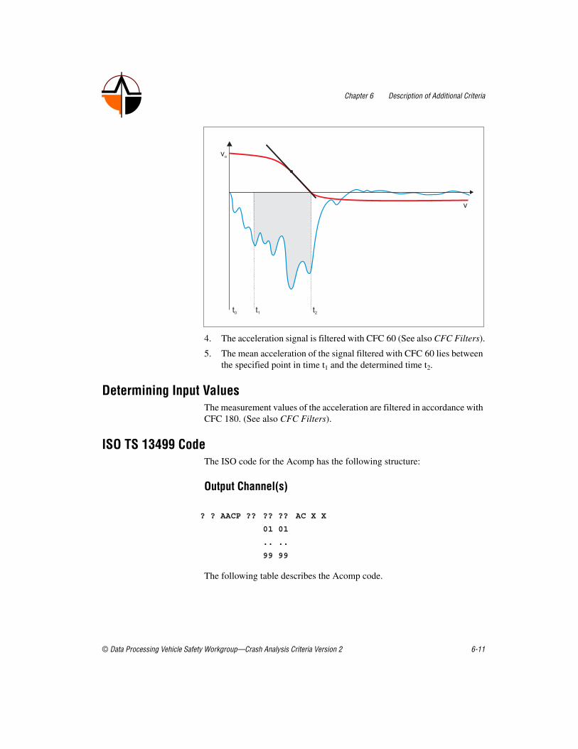
Chapter 6 Description of Additional Criteria
© Data Processing Vehicle Safety Workgroup—Crash Analysis Criteria Version 2 6-11
4. The acceleration signal is filtered with CFC 60 (See also CFC Filters).
5. The mean acceleration of the signal filtered with CFC 60 lies between the specified point in time t1 and the determined time t2.
Determining Input ValuesThe measurement values of the acceleration are filtered in accordance with CFC 180. (See also CFC Filters).
ISO TS 13499 CodeThe ISO code for the Acomp has the following structure:
Output Channel(s)
The following table describes the Acomp code.
? ? AACP ?? ?? ?? AC X X
01 01
.. ..
99 99

Chapter 6 Description of Additional Criteria
6-12 ©Data Processing Vehicle Safety Workgroup—Crash Analysis Criteria Version 2
The following table lists the additional channel header attributes for the Acomp.
Input Channel(s)? ? ???? ?? ?? ?? AC X D : Acceleration X, CFC 60
Part of Code Code Description
Test object ? Test object depending
Position ? Position depending
Main location AACP Average Acceleration during Compression Phase
Fine location 1 00; 01; …; 99 1. bis 99.
Fine location 2 00; 01; …; 99 1. bis 99.
Fine location3 00; 01; …; 99 1. bis 99.
Physical dimension AC AC = Acceleration
Direction X Longitudinal
Filter class X Without
Attribute Description
.Start time Start time of the interval belonging to the calculated value (e.g. for the HIC). Only for criteria that uses an interval and not a single point in time.
.End time End time of the interval belonging to the calculated value (e.g. for the HIC). Only for criteria that uses an interval and not a single point in time.
.Analysis start time Start of the time interval that has been taken into account for the calculation of the value.
.Analysis end time End of the time interval that has been taken into account for the calculation of the value.
.Channel 001
...
.Channel nnn
ISO Code of the first channel used for the calculation. Order of the channels used is arbitrary. Filtering of the channel should be indicated by the right filter class in ISO code at position 16.
.Method For Acomp calculation: valid values are: "Variant 1" or "Variant 2"

Chapter 6 Description of Additional Criteria
© Data Processing Vehicle Safety Workgroup—Crash Analysis Criteria Version 2 6-13
Example Codes1 0 AACP 00 00 01 AC X X : Average Acceleration during
Compression Phase #0011 0 AACP 00 01 27 AC X X : Average Acceleration during
Compression Phase #127
Relevant Laws and Regulations• Company standards
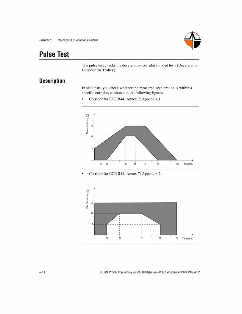
Chapter 6 Description of Additional Criteria
6-14 ©Data Processing Vehicle Safety Workgroup—Crash Analysis Criteria Version 2
Pulse Test The pulse test checks the deceleration corridor for sled tests (Deceleration Corridor for Trolley).
DescriptionIn sled tests, you check whether the measured acceleration is within a specific corridor, as shown in the following figures.
• Corridor for ECE R44; Annex 7; Appendix 1
• Corridor for ECE R44; Annex 7; Appendix 2

Chapter 6 Description of Additional Criteria
© Data Processing Vehicle Safety Workgroup—Crash Analysis Criteria Version 2 6-15
• Corridor for ECE R16
• Corridor for ECE-R17; 6.3.1

Chapter 6 Description of Additional Criteria
6-16 ©Data Processing Vehicle Safety Workgroup—Crash Analysis Criteria Version 2
• Corridor for ECE R80; Annex 4; Figure 1
• Corridor for FMVSS 206; Figure 5
• Corridor for FMVSS 208; S13.1; Figure 6

Chapter 6 Description of Additional Criteria
© Data Processing Vehicle Safety Workgroup—Crash Analysis Criteria Version 2 6-17
• Acceleration Impulse of the test sled in accordance with EN 1789 and DIN 75302, figure 7
Mathematical CalculationThe test must determine whether straight lines between two points exceed the specified range and whether the points are within the given range. As the following figure shows points and their connection lines must be within the corridor.
Determining Input ValuesThe measurement values of the acceleration are filtered in accordance with CFC 60. (See also CFC Filters).

Chapter 6 Description of Additional Criteria
6-18 ©Data Processing Vehicle Safety Workgroup—Crash Analysis Criteria Version 2
Relevant Laws and Regulations• ECE-R11; 3.5.1
• ECE-R16; Annex 8
• ECE R17
• ECE-R44; Annex 7
• ECE-R80; Annex 4; Figure 1
• EN 1789
• DIN 75302
• FMVSS 208; S13.1
• FMVSS 213

Chapter 6 Description of Additional Criteria
© Data Processing Vehicle Safety Workgroup—Crash Analysis Criteria Version 2 6-19
Gillis Index
DescriptionThe Gillis index is a characteristic value for the assessment of the vehicle security during frontal impact. To calculate the Gillis index, the acceleration measurement points of the head and thorax are required as well as the forces on the femur of the driver and the passenger.
Mathematical Calculation1. Calculate the HIC value and the HIC36 value for the driver and the
passenger.
2. Determine the 3 ms values of the resultant thorax acceleration for driver and passenger.
3. Determine the absolute maxima of the forces on the femur of the driver and the passenger.
The Gillis index is calculated with the following formula:
The Gillis-Index for 36 milliseconds is calculated with the following formula:
Determining Input ValuesSee also HIC and Xms.
Relevant Laws and Regulations—
with Indices D—driver, P—passenger, l—left, r—right
HIC HIC - value
HIC36 HIC36 value
F Absolute maxima of the forces on the femur

Chapter 6 Description of Additional Criteria
6-20 ©Data Processing Vehicle Safety Workgroup—Crash Analysis Criteria Version 2
NCAPNCAP is the abbreviation for New Car Assessment Program.
DescriptionIn order to evaluate the test results, the probabilities of head and thorax injuries according to Mertz (GM) and Prasad (Ford) are used.
Mathematical CalculationThe probability of head injuries is calculated with the following formula:
The probability of chest injuries is calculated with the following formula:
If head and thorax injuries occur simultaneously, a combined probability is calculated with the following formula:
The following classification is determined with the determined probability of Pcombined:
with HIC36 HIC36 value
with achest, 3 ms 3 3 ms value for chest acceleration
Pcombined ≤ 0,10 ★★★★★
0,10 < Pcombined ≤ 0,20 ★★★★
0,20 < Pcombined ≤ 0,35 ★★★
0,35 < Pcombined ≤ 0,45 ★★
Pcombined ≥ 0,45 ★

Chapter 6 Description of Additional Criteria
© Data Processing Vehicle Safety Workgroup—Crash Analysis Criteria Version 2 6-21
Determining Input Values—
ISO TS 13499 CodeThe ISO code for the NCAP has the following structure.
Output Channel(s)? ? NCAP ?? ?? ?? 00 0 X
The following table describes the NCAP code.
The following table lists the additional channel header attributes for NCAP.
Part of Code Code Description
Test object ? Test object depending
Position ? Position depending
Main location NCAP New Car Accessment Program
Fine location 1 ?? Fine Location 1 dependent
Fine location 2 ?? Fine Location 2 dependent
Fine location3 ?? Dummy type dependent
Physical dimension 00 Others
Direction 0 Without
Filter class X Without
Attribute Description
.Time The appropriate time where the calculated value occurred.
Analysis start time Start of the time interval that has been taken into account for the calculation of the value.
.Analysis end time End of the time interval that has been taken into account for the calculation of the value.
.Channel 001
...
.Channel nnn
ISO Code of the first channel used for the calculation. Order of the channels used is arbitrary. Filtering of the channel should be indicated by the right filter class in ISO code at position 16.
.Stars For NCAP calculation: Star rating in numerical form 1…5

Chapter 6 Description of Additional Criteria
6-22 ©Data Processing Vehicle Safety Workgroup—Crash Analysis Criteria Version 2
Input Channel(s)? ? HEAD ?? ?? ?? AC X A : Head Acceleration X? ? HEAD ?? ?? ?? AC Y A : Head Acceleration Y? ? HEAD ?? ?? ?? AC Z A : Head Acceleration Z? ? CHST ?? ?? ?? AC X A : Chest Acceleration X? ? CHST ?? ?? ?? AC Y A : Chest Acceleration Y? ? CHST ?? ?? ?? AC Z A : Chest Acceleration Z
Example Codes1 0 NCAP 00 00 00 00 0 X : New Car Assessment Program1 1 NCAP 00 00 00 00 0 X : New Car Assessment Program1 3 NCAP 00 00 00 00 0 X : New Car Assessment Program
Relevant Laws and Regulations• Refer for more information to the Internet address
www.nhtsa.dot.gov/cars/testing/ncap .

Chapter 6 Description of Additional Criteria
© Data Processing Vehicle Safety Workgroup—Crash Analysis Criteria Version 2 6-23
EuroNCAPEuroNCAP is the abbreviation for European New Car Assessment Program
DescriptionVehicles are assessed and given stars that indicate the level of safety. The following tests are performed:
• Front Impact
• Side Impact
• Pole Side Impact
• Pedestrian Test
Mathematical CalculationA EuroNCAP spreadsheet shows the test results as points.
Determining Input Values—
Relevant Laws and Regulations• European New Car Assessment Programs
• Refer to the Internet address www.euroncap.com for more information.
33 – 40 points ★★★★★
25 – 32 points ★★★★
17 – 24 points ★★★
9 – 16 points ★★
1 – 8 points ★
0 points
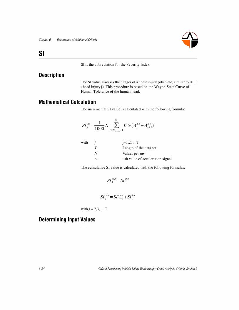
Chapter 6 Description of Additional Criteria
6-24 ©Data Processing Vehicle Safety Workgroup—Crash Analysis Criteria Version 2
SISI is the abbreviation for the Severity Index.
DescriptionThe SI value assesses the danger of a chest injury (obsolete, similar to HIC {head injury}). This procedure is based on the Wayne-State Curve of Human Tolerance of the human head.
Mathematical CalculationThe incremental SI value is calculated with the following formula:
The cumulative SI value is calculated with the following formulas:
with j = 2,3, ... T
Determining Input Values—
with j j=1,2, ... T
T Length of the data set
N Values per ms
A i-th value of acceleration signal

Chapter 6 Description of Additional Criteria
© Data Processing Vehicle Safety Workgroup—Crash Analysis Criteria Version 2 6-25
ISO TS 13499 CodeThe ISO code for the SI has the following structure:
Output Channel(s)? ? CHSI ?? ?? ?? 00 R X
The following table describes the SI code.
The following table lists the additional channel header attributes for the SI.
Part of Code Code Description
Test object ? Test object depending
Position ? Position depending
Main location CHSI Severity Index Chest
Fine location 1 ?? Fine Location 1 dependent
Fine location 2 ?? Fine Location 2 dependent
Fine location3 ?? Dummy type dependent
Physical dimension 00 Others
Direction R Resultant
Filter class X Without
Attribute Description
.Start time Start time of the interval belonging to the calculated value (e.g. for the HIC). Only for criteria that uses an interval and not a single point in time.
.End time End time of the interval belonging to the calculated value (e.g. for the HIC). Only for criteria that uses an interval and not a single point in time.
.Analysis start time Start of the time interval that has been taken into account for the calculation of the value.
.Analysis end time End of the time interval that has been taken into account for the calculation of the value.

Chapter 6 Description of Additional Criteria
6-26 ©Data Processing Vehicle Safety Workgroup—Crash Analysis Criteria Version 2
Input Channel(s)? ? CHST ?? ?? ?? AC X : Chest Acceleration X
Example Codes1 1 CHSI 00 00 H3 00 R X : Severity Index Chest
Relevant Laws and Regulations• SAE J885
.Channel 001
...
.Channel nnn
ISO Code of the first channel used for the calculation. Order of the channels used is arbitrary. Filtering of the channel should be indicated by the right filter class in ISO code at position 16.
.Filter Filter used: Only if all channels has been filtered with the same channel class! This is redundant to the information given in the ISO codes of each channel but easy to observe in the file.
Attribute Description

Chapter 6 Description of Additional Criteria
© Data Processing Vehicle Safety Workgroup—Crash Analysis Criteria Version 2 6-27
Integration
DescriptionAll numeric integration processes (differentiation processes) which return the starting values after an integration followed by differentiation or a differentiation with a subsequent integration are suitable.
Mathematical Calculation—
Determining Input Values
Note Note that numerical integration routine results are incorrect if there is an offset in the data set.
Relevant Laws and Regulations• SAE J1727, 3.1

Chapter 6 Description of Additional Criteria
6-28 ©Data Processing Vehicle Safety Workgroup—Crash Analysis Criteria Version 2
Differentiation
DescriptionAll those numeric differentiation processes (integration processes) are suitable, which return the starting values after an integration followed by differentiation or a differentiation with a subsequent integration.
Mathematical CalculationThe differentiation method in accordance with ECE R94 is (see also ): VC).
Determining Input Values—
Relevant Laws and Regulations• ECE R94, Annex 4, 6.2
• Directive 96/79/EG, Annex II, Appendix 2, 6.2
• SAE J1727, 3.1
with Δt Time interval between the single measurements in seconds

Chapter 6 Description of Additional Criteria
© Data Processing Vehicle Safety Workgroup—Crash Analysis Criteria Version 2 6-29
CFC FiltersCFC is the abbreviation for Channel Frequency Class
DescriptionThe CFC filters are analog or digital filters. The filters can be phased or un-phased. The following table lists the most common filter types.
Mathematical CalculationIn accordance with SAE J211, a 4-channel Butterworth low pass with linear phase and special starting conditions is used as a digital filter.
The filter sequence is described by the following difference equation:
The filter constants are calculated with the following formulas:
Filter Filter parameters
CFC 60 3 dB limit frequency 100 Hz
Stop damping –30 dB
Sampling frequency at least 600 Hz
CFC 180 3 dB limit frequency 300 Hz
Stop damping –30 dB
Sampling frequency at least 1800 Hz
CFC 600 3 dB limit frequency 1000 Hz
Stop damping –40 dB
Sampling frequency at least 6 khz
CFC 1000 3 dB limit frequency 1650 Hz
Stop damping –40 dB
Sampling frequency at least 10 khz

Chapter 6 Description of Additional Criteria
6-30 ©Data Processing Vehicle Safety Workgroup—Crash Analysis Criteria Version 2
The difference equation describes a two-channel filter: To realize a four-channel filter, the data of the two-channel filter has to run twice: once forwards and once backwards, to prevent phase displacements.
Note The filter constants wd is calculated in the ISO 6487 sample code differently to SAE J211:
Determining Input Values—
with X[t] Input data sequence
Y[t] Filtered output data sequence
a0, a1, a2, b1, b2 Filter constants varying with CFC
T Sampling rate in seconds

Chapter 6 Description of Additional Criteria
© Data Processing Vehicle Safety Workgroup—Crash Analysis Criteria Version 2 6-31
Relevant Laws and Regulations• SAE J211, 8.4.1
• ISO 6487, 4.5
• ISO 6487, 5.8

Chapter 6 Description of Additional Criteria
6-32 ©Data Processing Vehicle Safety Workgroup—Crash Analysis Criteria Version 2
FIR 100 FiltersFIR is the abbreviation for Finite Impulse Response
DescriptionFIR filters are digital filters.
Mathematical CalculationFilter characteristics in accordance with FMVSS 214, S6.13.5.4
• Passband frequency: 100 Hz
• Stopband frequency: 189 Hz
• Stopband gain: –50 dB
• Passband ripple: 0,0225 dB
NHTSA algorithm for FIR 100:
• CFC 180 phaseless
• Subsampling to 1600 Hz
• Removal of bias
• FIR filters in accordance with filter characteristic FMVSS 214
• Oversampling back to original sample rate
Determining Input Values—
Relevant Laws and Regulations• FMVSS 214, S6.13.5.4
• SAE J1727, 3.5

© Data Processing Vehicle Safety Workgroup—Crash Analysis Criteria Version 2 7-1
7Legislation and Directives
European Legislation• ECE–R80
• ECE–R94
• Directive 96⁄ 79/EG
• ECE–R95
• Directive 96⁄ 27/EG
• Directive 2004⁄ 90⁄ EG
• ECE–R17
American Legislation
Federal Motor Vehicle Safety Standard (49 CFR Part 571)• FMVSS 201
• FMVSS 208
• FMVSS 213
• FMVSS 214
Current American stipulations are also available in the Internet: www.gpoaccess.gov/cfr
Japanese Legislation• TRIAS 47
• TRIAS 63
Standards and Directives• SAE J1727
• SAE J1733
• SAE J2052
• SAE J211

Chapter 7 Legislation and Directives
7-2 ©Data Processing Vehicle Safety Workgroup—Crash Analysis Criteria Version 2
• ISO 6487
• ISO TS 13499
• DIN 75302
• EN 1789
• EuroNCAP; European New Car Assessment Programs, www.euroncap.com/content/test_procedures/introduction.php
• Robert A. Denton, Sign Conventions for Load Cells (S.A.E. J–211) Rev. 27AUG02

Chapter 7 Legislation and Directives
© Data Processing Vehicle Safety Workgroup—Crash Analysis Criteria Version 2 7-3
Lim
it Va
lues
The
fol
low
ing
tabl
e co
mpa
res
the
crit
eria
of
diff
eren
t tes
t typ
es.
Typ
eA
mer
ica
Eur
ope
Oth
er M
etho
ds
FMV
SS20
8FM
VSS
214
NC
AP
EC
E–R
9496
⁄79
⁄E
GE
CE
–R95
96⁄
27⁄
EG
Eur
oNC
AP
Eur
oNC
AP
Eur
oNC
AP
AD
AC
AM
uS
Fron
t Im
pact
Side
Im
pact
Fron
t/ Si
de I
mpa
ctFr
ont O
DB
Side
OD
BFr
ont I
mpa
ctSi
de I
mpa
ctSi
de P
ole
Fro
nt/ S
ide
Impa
ctF
ront
/ Sid
e Im
pact
Val
idit
yN
PR
M
12.5
.00
NP
RM
18
.9.9
819
72F
rom
199
8F
rom
199
8F
rom
200
3F
rom
200
3F
rom
200
3
Vel
ocit
y56
⁄48
km
⁄h
54 k
m⁄
h56
⁄61
km
⁄h
56 k
m⁄
h50
km
⁄h
64 k
m⁄
h50
km
⁄h
29 k
m⁄
h ca
rrie
r60
km
⁄h
55 k
m⁄
h
Bar
rier
Fixe
d B
ar.
Mob
.Def
.B
arR
igid
/Def
. B
ar.
Def
. Bar
.M
ob.D
ef.
Bar
.D
ef. B
ar.
Mob
.Def
.B
ar.
Pole
Ove
rlap
ping
100%
—10
0%⁄
—40
%40
%—
—40
%50
%
Impa
ct a
ngle
0×27
×0×
0×90
×0×
90×
90×
0º90
º
Tes
t w
eigh
t—
1,36
8 kg
— /
1368
kg
Add
it.
wei
ght
950
kgA
ddit.
w
eigh
t95
0 kg
—P
lus
lugg
age
950
kg
Res
trai
nt s
yst.
Pass
ive
activ
ex
xx
xx
xx
PA
SSE
NG
ER
S
Dri
ver
HII
I 5,
50,
95
%U
S-S
ID;
Spec
.H
III–
50%
U
S–S
IDH
III-
50 %
Eur
o-S
IDH
III-
50 %
Eur
o–S
ID
ES
–2 f
rom
11
⁄02
Eur
o–S
ID
ES
–2 f
rom
11
⁄02
HII
I–50
%⁄
E
uros
id50
%⁄
Eur
osi
d
Fro
nt s
eat
pass
.H
III
5, 5
0,
95%
——
HII
I-50
%—
HII
I-50
%—
—H
III-
50%
/Eur
osid
50%
⁄E
uros
id
Pos
. 4 -
beh
ind
driv
erH
III
12m
, 3
year
, 6
year
——
——
P3P
11⁄
2—
——

Chapter 7 Legislation and Directives
7-4 © Data Processing Vehicle Safety Workgroup—Crash Analysis Criteria Version 2
Pos
. 6 -
beh
ind
pass
enge
rH
III
12m
, 3–
year
, 6–
year
——
——
P11
⁄2
P3—
——
Tem
pera
ture
(m
easu
rem
ent
tim
e)20
,55–
22
,22º
C18
,89–
25
,56º
C—
19–2
2ºC
18–2
6ºC
19–2
2ºC
(>
5h)
18–2
6ºC
(>
5h)
18–2
6ºC
(>
5h)
——
SAF
ET
Y C
RIT
ER
IA1)
HIC
, HP
C≤1
000
(HIC
36)
≤700
(H
IC15
)
≤100
0≤1
000
≤100
0≤0
00
(HIC
36)2)
≤100
0 (H
IC36
)≤1
000
(HIC
36)
≤100
0≤1
000
Hea
d R
es 3
ms
——
—≤8
0g—
≤80g
1)—
≤80g
≤80g
≤80g
Hea
d ve
rt. 3
ms
——
——
—≤2
0g—
——
—
Nec
k –
Fle
x⁄E
xten
s.19
0⁄57
Nm
——
MO
C, F
z—
MO
C, F
z—
——
—
Tho
rax
T1
——
——
——
——
——
Tho
rax
T12
——
——
——
——
——
Rib
s—
——
——
——
——
—
Che
stR
es 3
ms
≤60g
—≤6
0g⁄
—≤6
0g—
≤60g
——
≤60g
≤60g
Che
st v
ert.
3m
s—
——
——
≤30g
——
——
Che
st c
ompr
essi
on≤7
6.2
mm
—≤7
6.2
mm
≤50
mm
≤42.
0 m
m≤5
0 m
m≤4
2.0
mm
—≤5
0⁄≤4
2mm
≤50⁄
≤42m
m
VC
≤1,0
ms–1
—≤1
,0 m
s–1⁄
—≤1
,0 m
s–1≤1
,0 m
s–1≤1
,0 m
s–1≤1
,0 m
s–1—
≤1,0
ms–1
—≤1
,0 m
s–1⁄
—
TT
I—
85⁄
90g
85⁄
90g
——
——
——
—
Abd
omen
——
—2,
5 kN
—2,
5 kN
—2,
5 kN
2,5
kN
Pel
vis
—13
0g13
0g—
——
——
——
Pub
ic S
ymph
ysis
——
——
≤6 k
N—
≤6 k
N—
≤6 k
N≤6
kN
Fem
ur10
kN
—≤1
0 kN
Forc
e⁄T
ime
—Fo
rce⁄
Tim
e—
—Fo
rce⁄
Tim
eFo
rce⁄
Tim
e
Typ
eA
mer
ica
Eur
ope
Oth
er M
etho
ds

Chapter 7 Legislation and Directives
© Data Processing Vehicle Safety Workgroup—Crash Analysis Criteria Version 2 7-5
1) C
hild
ren
have
dif
fere
nt in
jury
cri
teri
a.
2) T
he li
mit
valu
es d
iffe
r ac
cord
ing
to v
ehic
le e
quip
men
t and
hea
d co
ntac
t.
Kne
e—
——
15 m
m—
15 m
m—
—15
mm
15 m
m
Low
er le
g—
——
≤ 8 k
N—
≤ 8 k
N—
—≤ 8
kN
≤ 8 k
N
Tib
ia I
ndex
——
—≤1
,3—
≤1,3
——
≤1,3
≤1,3
Typ
eA
mer
ica
Eur
ope
Oth
er M
etho
ds