Embed Size (px)
Citation preview
CRANFIELD UNIVERSITY
FEI GAO
Continuing Airworthiness Policy and Application to Flying Crane Aircraft
School Of Engineering Aircraft Design
MSc by Research Academic Year: 2010 - 2011
Supervisor: Mr. Phil Stocking January 2011

CRANFIELD UNIVERSITY
SCHOOL OF ENGINEERING Aircraft Design Programme
MSc by Research
Academic Year 2010 - 2011
FEI GAO
Continuing Airworthiness Policy and Application to Flying Crane Aircraft
Supervisor: Mr. Phil Stocking
January 2011
© Cranfield University 2011. All rights reserved. No part of this publication may be reproduced without the written permission of the copyright
owner.

i
This thesis has been assessed as of satisfactory standard for the award of a Master of Science degree by research. This thesis covers the part of the assessment concerned with the Individual Research Thesis. Readers must be aware that the work contained is not necessarily 100% correct, and
caution should be exercised if the thesis of the data it contains is used for future work. If in doubt please or to the supervisor named in the thesis, or the Department of Aerospace Technology.

ii
iii
ABSTRACT
This project is part of a collaborative MSc training programme between the
Aviation Industries of China (AVIC) and Cranfield University, aiming at
enhancing the competitiveness of AVIC in both international and domestic
aviation market through applying continuing airworthiness policies in the whole
aircraft development process.
The arrangement of the research project is that all students start with a Group
Design Project which is based on the Flying Crane Project provided by AVIC.
Individual research projects will address some aspects of the Flying Crane
Project during the Group Design Project, and then further developed during the
period for individual projects. The aim of this research is to apply the
airworthiness requirements and the methodology of the Maintenance Steering
Group logic (MSG-3) in the Flying Crane Project. This is because that
maintenance is one of the key factors of Continuing Airworthiness, and MSG-3
logic is the most accepted and approved method to develop scheduled
maintenance for civil aircrafts.
The main objectives of this project include: (1) To investigate current Continuing
Airworthiness regulations, including European airworthiness requirements (as
the main regulation to comply with) and Chinese airworthiness regulations (as
an important reference and supplement to the research); (2) To investigate the
main analysis methodology of reliability and maintainability, including Damage
Tolerance and Failure Mode and Effect Analysis (FMEA); (3) To analyse the
data resulted from the Group Design Project using MSG-3 logic to produce a set
of Continuing Airworthiness instructions, for the operator and maintenance
organisation of the aircraft, from the design organization’s perspective; (4) To
develop Continuing Airworthiness instructions for airline operators to compose
maintenance programmes for Flying Crane aircrafts, including maintenance
tasks and intervals for the selected airframe systems and structural components;
and (5) To identify applicable maintenance organisations in China for Flying

iv
Crane aircrafts in accordance with both European and Chinese airworthiness
requirements.
On completion of this research, two aspects of Continuing Airworthiness have
been investigated, including maintenance programme and maintenance
organization. With MSG-3 logic, the author developed the maintenance plan for
three structural components (fuselage skin panel, wing root joint, and
fin-fuselage attachment) and one airframe system (fuel system) based on results
from the Group Design Project. The author also investigated the Chinese
domestic aircraft maintenance companies, and selected suitable maintenance
organizations based on technical and economical criteria.
Keywords:
Airworthiness Regulations, Regulatory Authority, Continuing Airworthiness
instructions, Scheduled Maintenance Tasks and Intervals, MSG-3, Cabin Layout,
Floor Beam
v
ACKNOWLEDGEMENTS
First of all, I would like to appreciate my supervisor Mr Phil Stocking for his
advice, guidance and patience during my research.
Many thanks are dedicated to Dr Xiang Zhang and Dr Shijun Guo for their advice
and kindness during this academic year at Cranfield University.
I am also deeply grateful to my classmates for their help professionally and
personally.
Finally, I want to say thanks to all my family for their continuous love and
support.

vii
TABLE OF CONTENTS
ABSTRACT ........................................................................................................ iii ACKNOWLEDGEMENTS ................................................................................... v LIST OF FIGURES ............................................................................................. ix LIST OF TABLES ............................................................................................... x GLOSSARY OF TERMS .................................................................................... xi 1 Introduction ................................................................................................. 1
1.1 Project Background ......................................................................... 1 1.2 Airworthiness in the Chinese Aviation Industry ................................ 1 1.3 Overview of the Group Design Project............................................. 2 1.4 Overview of the Individual Research Project ................................... 2 1.5 Project Aims and Objectives ............................................................ 3 1.6 Thesis Structure .............................................................................. 5
2 The Group Design Project ........................................................................... 6 2.1 Cabin Layout Design ....................................................................... 6 2.2 Cabin Floor Design .......................................................................... 7 2.3 Airworthiness Management ............................................................. 8 2.4 Group Design Project Conclusion .................................................... 8
3 Literature Review ...................................................................................... 10 3.1 Definition of Airworthiness ............................................................. 10 3.2 Main Airworthiness Authorities and Standards .............................. 12
3.2.1 The International Civil Aviation Organization ................................. 12 3.2.2 The European Aviation Safety Agency .......................................... 13 3.2.3 The Civil Aviation Administration of China ..................................... 17 3.2.4 Relevant Airworthiness Requirements ........................................... 17
3.3 Continuing Airworthiness ............................................................... 18 3.3.1 Content of Continuing Airworthiness ............................................. 20 3.3.2 Continuing Airworthiness Instruction.............................................. 21 3.3.3 Comparison between CCAR & EASA Continuing Airworthiness Regulation System .................................................................................... 21
3.4 Introduction to ATA MSG-3 Logic .................................................. 23 3.4.1 Development of MSG-3 ................................................................. 23 3.4.2 Mission of MSG-3 .......................................................................... 24 3.4.3 The Author’s Understanding about MSG-3 .................................... 24
3.5 The Continuing Airworthiness Applied on Flying Crane Project ..... 25 3.5.1 Airframe System ............................................................................ 26 3.5.2 Structural Component .................................................................... 26
3.6 Research to Non-destructive Tests ............................................... 27 3.6.1 Visual Inspection ........................................................................... 27 3.6.2 Radiographic Inspection ................................................................ 28 3.6.3 Ultrasonic Testing .......................................................................... 30 3.6.4 Eddy Current Testing ..................................................................... 32 3.6.5 Dye Penetrant Inspection .............................................................. 34 3.6.6 Magnetic Particle Inspection .......................................................... 35 3.6.7 Infrared Inspection ......................................................................... 36 3.6.8 Comparison of Non-destructive Testing Methods .......................... 37
3.7 Summary ....................................................................................... 40
viii
4 Scheduled Maintenance Development Based On MSG-3 Logic ............... 41 4.1 Obligations of Type Certificate Holders ......................................... 41 4.2 Scheduled Maintenance for Selected Structures ........................... 42
4.2.1 Introduction to Selected Structural Items ....................................... 42 4.2.2 Scheduled Structural Maintenance Development Procedure ........ 45 4.2.3 Define aircraft zones or areas (P1) and define aircraft structural items (P2) .................................................................................................. 46 4.2.4 Identifying Structural Significant Items (D1) ................................... 47 4.2.5 Generating Structural Significant Items List (P3) ........................... 48 4.2.6 AD/ED/CPCP Analysis for Metallic Structures (P7 – P9) ............... 48 4.2.7 To Determine Damage Tolerant or Safe Life ................................. 54 4.2.8 Fatigue Damage Analysis .............................................................. 55 4.2.9 Generating Preliminary Scheduled Structural Maintenance .......... 58
4.3 Scheduled Maintenance for Selected System ............................... 61 4.3.1 Introduction to Fuel System ........................................................... 62 4.3.2 Maintenance Significant Items Selection ....................................... 66 4.3.3 Analysis Procedure ........................................................................ 67 4.3.4 Category of Failure Effects (First Level) ........................................ 67 4.3.5 Tasks Development (Category 5, Second Level) .......................... 70 4.3.6 Tasks Development (Category 6, Second Level) .......................... 74 4.3.7 System Maintenance Task Intervals Development ........................ 76
4.4 Continuing Airworthiness Instructions ............................................ 78 4.4.1 Organizations of Continuing Airworthiness instructions Development 78 4.4.2 Proposed Continuing Airworthiness Instructions of Flying Crane .. 79
5 Selection of Chinese Maintenance Organizations ..................................... 84 5.1 The Role of Maintenance Organizations........................................ 84 5.2 Selection Criteria ........................................................................... 86
5.2.1 Maintenance Approval Class and Rating ....................................... 86 5.2.2 Hangar Capacity ............................................................................ 86 5.2.3 Market Performance and Experience ............................................ 87 5.2.4 Technical Requirements ................................................................ 87 5.2.5 Accessibility ................................................................................... 87
5.3 Selecting Maintenance Organizations in China ............................. 87 6 Conclusion and Further Work .................................................................... 95
6.1 Research Findings ......................................................................... 95 6.2 Aim and Objectives Achieved ........................................................ 97 6.3 Limitation of MSG-3 Logic ............................................................. 98 6.4 Recommendation for Further Work ............................................... 99
6.4.1 Required Data to Implement MSG-3 Logic .................................... 99 6.4.2 Further Research Related to MSG-3 ........................................... 100
References ..................................................................................................... 101 APPENDICES ................................................................................................ 104
ix
LIST OF FIGURES
Figure 2-1 Floor Panel Designed .................................................................. 7
Figure 3-1 Flight safety represented as three links in a chain ................. 11
Figure 3-2 Regulations Structure of EASA (EASA, 2010) ......................... 14
Figure 3-3 Main Players in Continued Airworthiness (John W Bristow and Simon Place, 2010) ............................................................................... 19
Figure 3-4 Layout of Radiographic Inspection (NDT Education Resource Center, 2011) ......................................................................................... 29
Figure 3-5 Layout of Ultrasonic Testing (NDT Education Resource Center, 2011) ...................................................................................................... 31
Figure 3-6 Layout of Eddy Current Testing (NDT Education Resource Center, 2011) ......................................................................................... 33
Figure 3-7 "Capillarity Phenomenon" during Dye Penetrant Inspection (NDT Education Resource Center, 2011) ............................................ 34
Figure 3-8 Layout of Magnetic Particle Inspection (NDT Education Resource Center, 2011) ........................................................................ 36
Figure 4-1 Aft Fuselage Skin of Flying Crane ............................................ 43
Figure 4-2 Fin-Fuselage Attachment of Flying Crane ............................... 44
Figure 4-3 Wing root joint............................................................................ 45
Figure 4-4 MSG-3 logic diagram for structures (ATA, 2003, MSG-3 Logic) ................................................................................................................ 46
Figure 4-5 MSG-3 AD/ED logic diagram - metallic ..................................... 49
Figure 4-6 MSG-3 Fatigue Damage logic diagram (ATA, 2003, MSG-3 Logic) ..................................................................................................... 56
Figure 4-7 Flying Crane fuel system structure .......................................... 63
Figure 4-8 Level 1 System Logic - Part 1 of 2 (ATA, 2003, MSG-3 Logic) 68
Figure 4-9 Level 1 System Logic - Part 2 of 2 (ATA, 2003, MSG-3 Logic) 68
Figure 4-10 Functional Failures Categorized as Evident Safety Effects (ATA, 2003, MSG-3 Logic) .................................................................... 71
Figure 4-11 The P-F curve (John Moubray, 1997) ..................................... 72
Figure 4-12 Functional Failures Categorized as Evident Operational Effects (ATA, 2003, MSG-3 Logic) ....................................................... 75
Figure 5-1 the Role of Maintenance Organization in Continuing Airworthiness ........................................................................................ 85

x
LIST OF TABLES
Table 3-1 Comparison of NDT Methods ..................................................... 38
Table 4-1 Structural Significant Item List .................................................. 48
Table 4-2 Main Accidental Damage and Environmental Deterioration of selected structures ............................................................................... 50
Table 4-3 AD/ED requirements for selected structures ............................ 52
Table 4-4 Structural maintenance tasks and intervals due to AD/ED ...... 53
Table 4-5 Category as damage tolerant or safe-life .................................. 55
Table 4-6 Structural maintenance tasks and intervals due to Fatigue Damage .................................................................................................. 58
Table 4-7 Scheduled Maintenance for Selected Structures ..................... 60
Table 4-8 A Section of FMEA Analysis Form (Wangfeng Yang, Cranfield University Group Design Report, 2010) .............................................. 64
Table 4-9 Failure Effect Category of Selected Maintenance Significant Items ...................................................................................................... 66
Table 4-10 Proposed Maintenance Tasks for Category 5 Functional Failures .................................................................................................. 74
Table 4-11 Proposed Maintenance Tasks for Category 6 Functional Failures .................................................................................................. 76
Table 4-12 Proposed Maintenance Schedule for Structures and Systems of Flying Crane ...................................................................................... 80
Table 5-1 Technical Requirements for Maintenance tasks at Different Interval ................................................................................................... 88
Table 5-2 Maintenance Organization Selection Matrix ............................. 89
xi
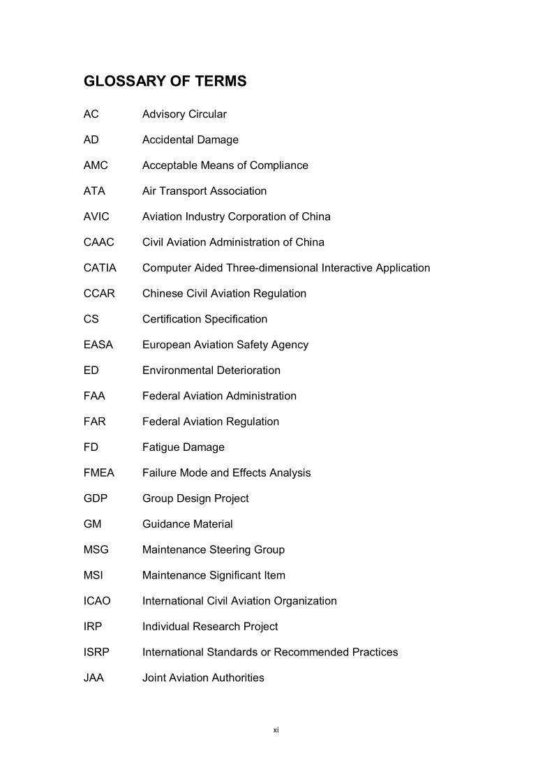
GLOSSARY OF TERMS
AC Advisory Circular
AD Accidental Damage
AMC Acceptable Means of Compliance
ATA Air Transport Association
AVIC Aviation Industry Corporation of China
CAAC Civil Aviation Administration of China
CATIA Computer Aided Three-dimensional Interactive Application
CCAR Chinese Civil Aviation Regulation
CS Certification Specification
EASA European Aviation Safety Agency
ED Environmental Deterioration
FAA Federal Aviation Administration
FAR Federal Aviation Regulation
FD Fatigue Damage
FMEA Failure Mode and Effects Analysis
GDP Group Design Project
GM Guidance Material
MSG Maintenance Steering Group
MSI Maintenance Significant Item
ICAO International Civil Aviation Organization
IRP Individual Research Project
ISRP International Standards or Recommended Practices
JAA Joint Aviation Authorities

xii
JAR Joint Aviation Requirements
SSI Structural Significant Item
TC Type Certification
TCH Type Certification Holder

1
1 Introduction
1.1 Project Background
This is a collaborative project between Aviation Industries of China (AVIC) and
Cranfield University. With the aim of enhancing competitiveness in both
international and domestic aviation industry, the Aviation Industries of China,
the biggest aeronautical product manufacturer in China, started this training
and research project in collaboration with the School of Engineering, Cranfield
University in 2008. Since 2008 to 2010, AVIC has sent three cohorts of aircraft
engineers to Cranfield University.
The research project assigned to the students in the first three cohorts was
mainly based on the design of the “Flying Crane”, a 130-seat civil aircraft under
development in AVIC. All students started a Group Design Project, in which
AVIC students experienced the whole procedure of civil aircraft design,
including the Conceptual Design Phase, Preliminary Design Phase and
Detailed Design Phase, followed by an individual project, all completed each
within one year. Most of these students (including the author) extended or
spread their research in Group Design Project phase as their topic of Individual
Research Project. The author’s individual research topic is the application of
continuing airworthiness policy in the whole aircraft development process,
especially in the Chinese aviation industry.
1.2 Airworthiness in the Chinese Aviation Industry
Ever since the end of World War II, the development of civil aviation in the
United Kingdom, the United States, and Russia has proved that, the capability
of airworthiness certification is one of the critical factors in civil aircraft
development.

2
Nowadays, Chinese aviation industry is experiencing a period of rapid
development. However, compared with western countries which have mature
aircraft development processes, procedures and technologies, airworthiness is
still a weak point in the Chinese aviation business chain.
Airworthiness certification of independent civil aircraft design in China started
from the ARJ-21 (Advanced Regional Jet of 21st Century) project. Due to the
certification plan, the Type Certificate of AJR21 is proposed to be released by
the end of 2011. Therefore it is clear that, China still has no experience of
maintaining an independent civil aircraft design under any airworthiness
regulations.
Consequently, Continuing Airworthiness, which covers operation and
maintenance in aircrafts’ service life, is considered as one of the most serious
“short board” of Chinese aviation industry.
1.3 Overview of the Group Design Project
As mentioned above, all students started with a Group Design Project. In the
academic year 2010-11 Group Design Project, the author’s group focused on
the Detailed Design Phase of the Flying Crane project, which is considered as
the extension and continuance of the Preliminary Design Phase accomplished
in the academic year 2009 project. In this group, the author was responsible
for three parts of the work: passenger cabin layout, floor structure design, and
airworthiness management.
1.4 Overview of the Individual Research Project
As mentioned previously, because of the lack of experience in designing and
maintaining civil aircraft independently, airworthiness certification, especially
Continuing Airworthiness is one of the main weak areas of Chinese aviation
industry. Based on this background, the author carried out a research into
3
Continuing Airworthiness work during Type design phase of civil aircrafts,
using data from the Flying Crane project. Note that the terminology ‘Type’
stands for a specific aircraft model in this thesis.
Continuing Airworthiness is a series of tasks, covering almost every aspect of
a Type of aircraft including design, certification, operation, and maintenance.
Among those aspects, the author selected ‘maintenance’ as an application
area aiming at developing the maintenance plan. The reasons behind the
decision are the following:
The maintenance plan is supposed to be accomplished by the end of
Detailed Design Phase and approved by the Regulatory Authority as a
main supportive document for Type certification;
Most of required design and analysis data are available from the results of
the Group Design Phase; and
In both the Chinese Civil Aviation Regulation (CCAR) and the European
Aviation Safety Agency (EASA) regulation systems, the same logic
Maintenance Steering Group – 3 (MSG-3) was employed as the guideline
to developing the maintenance tasks and intervals.
1.5 Project Aims and Objectives
As previously mentioned, this research is an extension of the Group Design
Project, which is based mainly on the results of airframe system and structural
components design, and will address issues related to Continuing
Airworthiness from aircraft manufacturer’s perspective.
Therefore, the aim of this research is to prove one means of compliance to
satisfying the EASA requirements related to Continuing Airworthiness, by

4
applying the airworthiness requirements and the methodology of the
Maintenance Steering Group logic (MSG-3) in the Flying Crane Project of the
Chinese Aviation Industries (AVIC).
For the purpose of achieving the research aim, the following objectives were
established:
To investigate current Continuing Airworthiness regulations, including
European airworthiness requirements (as the main regulation to comply
with) and Chinese airworthiness regulations (as an important reference
and supplement to the research);
To investigate the main analysis methodology of reliability and
maintainability, including Damage Tolerance and Failure Mode and Effect
Analysis (FMEA);
To analyse the data resulted from the Group Design Project using MSG-3
logic to produce a set of Continuing Airworthiness instructions, for the
operator and maintenance organisation of the aircraft, from the design
organization’s perspective;
To develop Continuing Airworthiness instructions for airline operators to
compose maintenance programmes for Flying Crane aircrafts, including
maintenance tasks and intervals for the selected airframe systems and
structural components; and
To identify applicable maintenance organisations in China for Flying Crane
aircrafts in accordance with both European and Chinese airworthiness
requirements.
5
1.6 Thesis Structure
The first Chapter of this thesis gives a general introduction to the research
project, including the origin and purpose of the project, the main content of the
Group Design Project and Individual Research Project, and the aim and
objectives of this research.
In Chapter Two, the author’s work accomplished in the Group Design Project
is described, including passenger cabin layout, floor structure design, and
airworthiness management.
Literature review is the content of Chapter Three, as well as the methodology
Maintenance Steering Group – 3 (MSG-3) logic and input from detailed design
phase of this research.
The research methodology is applied to specific design data in Chapter Four.
In addition, it comes to a proposed scheduled maintenance plan, including
maintenance tasks and intervals for selected structures and systems.
Chapter Five contains an assessment of the Chinese aircraft maintenance
organizations in accordance with airworthiness regulations and manufacturer’s
requirements.
In the end, the research outcome is concluded in Chapter Seven. And some
comments from the author’s perspective are proposed for future research.
6
2 The Group Design Project
During the Group Design Project phase in academic year 2010 – 2011, the
author’s group focused on the Detailed Design Phase of a 130-seat airliner
Flying Crane, based on the results of the preliminary design phase from the
previous group in academic year 2009 – 2010.
In this chapter, the author will present the main results from his work in Group
Design Project phase:
Cabin Layout;
Floor Design; and
Airworthiness Management.
2.1 Cabin Layout Design
For the cabin layout design, the author mostly kept the design style and
functional components from the preliminary design phase.
To verify the internal arrangement, the author collected and compared the seat
pitch and seat width of several most satisfactory airline worldwide with Flying
Cranes. And then, based on the investigation and comparison of several most
professional aerospace internal suppliers on the market, the author selected
Recaro Aircraft Seating as the seating supplier of the Flying Crane. Their
products BV3510 and BL4400 were the prototypes with those the CATIA CAD
models of economy class and Business class seats were developed.
In addition, the author finalised the 3D-model of passenger cabin with CATIA
V5 R17. The CATIA model contained passenger seats (economy and
business class), galleys, wardrobes, lavatories, emergency equipments
(including fire extinguishers and emergency lights).
7
2.2 Cabin Floor Design
This part of work includes the floor panel design and floor supporting structure
design.
For the floor panel, there were three general requirements: to strengthen the
high load areas, to avoid corrosion, and to use materials with light weight and
high resistance.
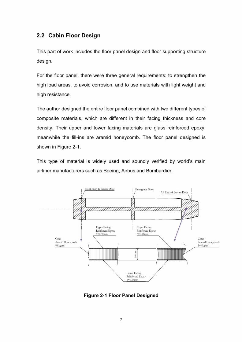
The author designed the entire floor panel combined with two different types of
composite materials, which are different in their facing thickness and core
density. Their upper and lower facing materials are glass reinforced epoxy;
meanwhile the fill-ins are aramid honeycomb. The floor panel designed is
shown in Figure 2-1.
This type of material is widely used and soundly verified by world’s main
airliner manufacturers such as Boeing, Airbus and Bombardier.
Figure 2-1 Floor Panel Designed
8
For the floor beam and floor vertical struts design, on the basis of the
preliminary design, the author changed the material and redesigned the cross
section of floor beam. And the vertical floor struts design, which had not been
covered in preliminary design phase, was finished in this work.
The specific analysis and calculation process is shown in Appendix A.
2.3 Airworthiness Management
In the Preliminary Design Phase, other researchers have already determined
the Airworthiness Regulations to comply with, the airworthiness management
workflow, and the main method of airworthiness management. Therefore, in
the Detailed Design Phase, the author followed the airworthiness work related
to the structure design from the Preliminary Design Phase, and updated in
accordance with the results accomplished in the Detailed Design Phase.
In the Group Design Project, the author was responsible for:
Making the Type certification plan for Flying Crane project;
Adding and adjusting the choice of clauses in CCAR-25;
Updating the Airworthiness Compliance Matrix.
This part of work will be described in Appendix B.
2.4 Group Design Project Conclusion
In the Group Design Project, the author was responsible for passenger cabin
layout, cabin floor, and airworthiness.
From passenger cabin and cabin floor design, the author learnt much about
internal components of aircrafts, component supplier assessment, as well as
aircraft structure design and analysis, which were all totally new to the author.

9
On the other hand, with the research of airworthiness, the author deeply
understood the concept and tasks of airworthiness as the role of manufacturer,
which were considered as the basis of the author’s Individual Research Project
in Continuing Airworthiness.
10
3 Literature Review
In this chapter, the author presented a general introduction to airworthiness,
including main airworthiness organisations and their regulations, especially
those related to Continuing Airworthiness. In addition, the methodology of
MSG-3 (Maintenance Steering Group - 3) logic was presented. Finally, seven
of the most common non-destructive testing methods were investigated.
3.1 Definition of Airworthiness
According to a number of published articles, the concept of AIRWORTHINESS
is defined in a variety of ways. However, there are commonalities among these
articles, i.e., the close link between airworthiness and safety.
“Safety is the condition of being safe from undergoing or causing hurt, injury, or
loss” (Merriam-Webster Online, available at: http://www.merriam-webster.com/,
accessed 10 Sep 2010).
When talking about safety related to aviation industry, the concept of
Airworthiness is used to assess whether an aircraft is safe enough or not.
The following shows several different definitions of airworthiness based on
different perspectives and understanding:
“Fit for operation in the air” (Merriam-Webster Online available at:
http://www.merriam-webster.com/, accessed 10 Sep 2010).
“A definition of airworthiness can be found in the Italian RAI-ENAC Technical
Regulations: for an aircraft, or aircraft part, [airworthiness] is the possession of
the necessary requirements for flying in safe conditions, within allowable limits”
(Filippo De Florio, 2006).
11
The author understands airworthiness as an inherent property of aeronautical
products, which can be created and maintained by human-being, with the aim
to ensure the safety of flight within expected environment.
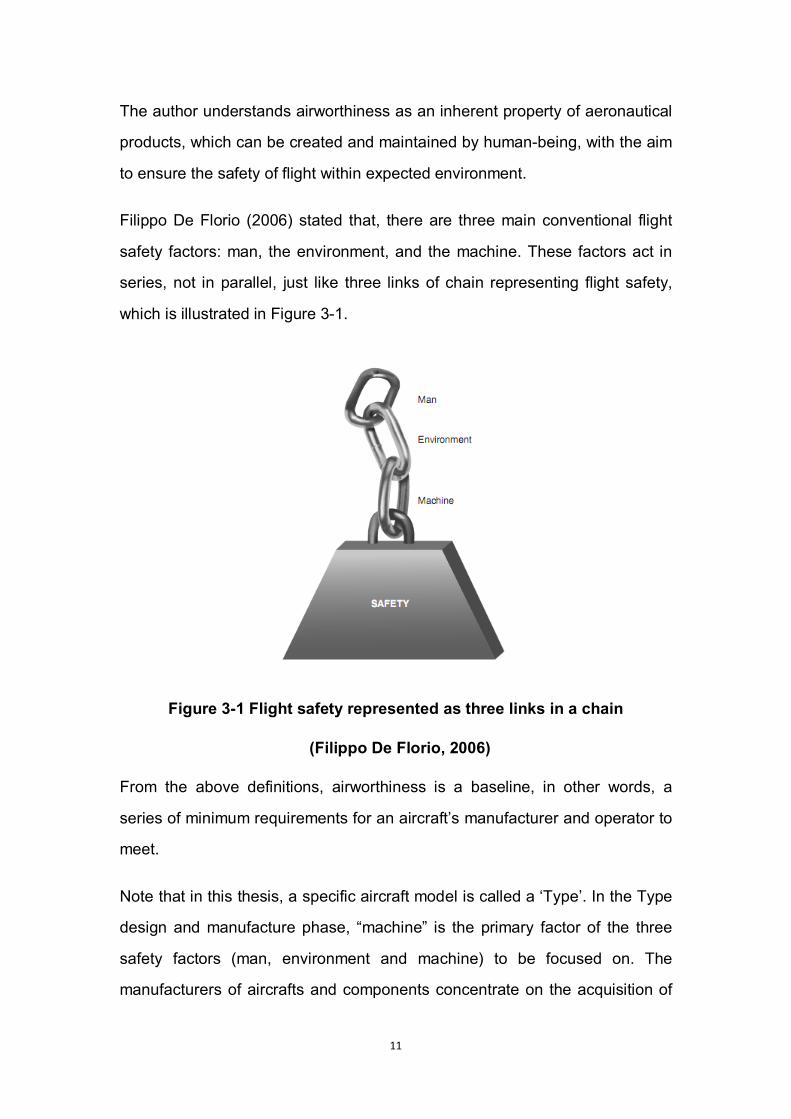
Filippo De Florio (2006) stated that, there are three main conventional flight
safety factors: man, the environment, and the machine. These factors act in
series, not in parallel, just like three links of chain representing flight safety,
which is illustrated in Figure 3-1.
Figure 3-1 Flight safety represented as three links in a chain
(Filippo De Florio, 2006)
From the above definitions, airworthiness is a baseline, in other words, a
series of minimum requirements for an aircraft’s manufacturer and operator to
meet.
Note that in this thesis, a specific aircraft model is called a ‘Type’. In the Type
design and manufacture phase, “machine” is the primary factor of the three
safety factors (man, environment and machine) to be focused on. The
manufacturers of aircrafts and components concentrate on the acquisition of

12
TC (Type Certificate), PC (Production Certificate), and C of A (the Certificate of
Airworthiness).
Once an aircraft is delivered to an operator and/or a maintenance organisation,
accompanied by the introduction of Continuing Airworthiness (which will be
explain in more detail later) during operation phase, the other two factors, man
and environment come into the stage.
There’s one point needs to be emphasized, which is that, there is no strict
boundary between the phase of type design/manufacture and operation. For
instance, before the delivery of an aircraft, the manufacture should issue the
maintenance plan to the operator. The document would include required
qualification and operation guide for maintenance personnel. The operator has
the obligation to feedback about the aircraft’s defect and performance to the
manufacturer to improve the maintenance plan as well.
3.2 Main Airworthiness Authorities and Standards
3.2.1 The International Civil Aviation Organization
The International Civil Aviation Organization (ICAO) was initially launched and
headquartered in Montreal, Canada. It has a history of over 60 years. Having
been developed continuously since its establishment, ICAO has over 180
contracting states at present. ICAO concentrates on developing a safe, sound,
effective and retainable civil aviation industry. (ICAO, available at:
http://www.icao.int/)
To achieve its objective in civil aviation, ICAO established and has been
implementing and completing 18 annexes, which are also entitled ISRP,
International Standards and Recommended Practices. The International
Standards are commonly agreed and executed as directives by every member
states. Recommended Practises are the most accepted but not the restricted
13
approach to achieve the standards. Among all these 18 annexes, Annex 6
(Operation of Aircraft) and Annex 8 (Airworthiness of Aircraft) have close
relationship with Continuing Airworthiness.
3.2.2 The European Aviation Safety Agency
When talking about the European Aviation Safety Agency (EASA), the Joint
Aviation Authorities (JAA) has to be mentioned. Before EASA, the competent
authority was JAA, which established and implemented the Joint Aviation
Requirements (JARs), and enabled the collaboration among member states,
as well as external authorities. (EASA, available at:
http://easa.europa.eu/home.php)
However, JAR was not able to perform legally to every member states within
JAR. Member states needed to develop their own aviation regulation systems,
which delayed the integrity of European Union in a certain level.
In that condition, EASA was organized as an independent European legal
body, which administrates and issues requirements in a legal level.
EASA takes responsibility for drafting new legislation, implementing safety
rules, issuing approvals for products and organisations, and authorizing
non-EU operators.
EASA’s regulation structure could be clearly illustrated in Figure 3-2.

14
Figure 3-2 Regulations Structure of EASA (EASA, 2010)
The Basic Regulation (EC) No 216/2008 of the European Parliament and of
the Council of 20 Feb 2008 states common rules in the field of civil aviation
and establishes the EASA. It is applied to design, production, maintenance
and operation of aeronautical products, parts, appliance, and personnel and
organisations involved in these procedures as well. And the principal objective
is to establish a high uniform level of civil aviation safety in Europe. (The
European Parliament and the Council, 2008)
One of the Implementing Rules, Regulation No 1702/2003, is “for the
airworthiness and environmental certification of aircraft and related products,
parts and appliances, as well as for the certification of design and production
organisations” (EASA, 2003). It contains Part-21 as its Annex I, and 10
appendices consisting of EASA unified forms related to certification
procedures including application, authorisation, permits, release, etc. The Part
15
21 is about certification of aircraft and related products, parts and appliances,
and of design and production organisations. Some clauses selected out from
Part 21 are closely related to the author’s study. These clauses will be list later
on in this chapter.
The EASA airworthiness codes, which are Certification Specifications, derived
from and have replaced JARs step by step since the establishment of EASA.
The CS codes are compulsorily prescribed and implemented by the authority.
The technical requirements defined in CS codes are mostly impact on
aeronautical products’ design and manufacture phase, which is considered as
initial airworthiness stage.
The CS-25, Certification Specification for Large Aeroplanes, altogether with its
AMCs and GMs (which will be introduced later on) have been taken into the
author’s study. The particular clauses will be list later in this chapter.
The Regulation (EC) No 2042/2003 is the Implementing Rule on the
Continuing Airworthiness of aircraft and aeronautical products, parts and
appliances, and on the approval of organisations and personnel involved in
these tasks. It establishes common technical requirements and administrative
procedures for the Continuing Airworthiness of aeronautical products. Annex I,
Part-M, Continuing Airworthiness management and Annex II, Part-145,
Maintenance Organization Approval, is both closely related to the author’s
work. The Annex III, Part-66, Certifying staff and Annex IV, Part-147, Training
organizations requirements are both involved in the study as well.
Part M – Continuing Airworthiness
Part-145 is the Annex II of Regulation (EC) No 2042/2003. It presents the
requirements for the maintenance organisations to get qualified as approved
maintenance organisations from the Continuing Airworthiness point of view,
16
and activities and procedures the competent authorities would take to have a
maintenance organisation under certification due to different conditions.
Part-145 regulates applicant organisations from aspects of, such as, personnel,
facilities, system (including data transfer and occurrence reporting, etc.),
quality, etc. Likewise, ACMs and GMs to Part-145 are important supplement
and directive material during the process of study.
Part-145 Maintenance Organization Approval
Part-145 is Annex II of Regulation (EC) No 2042/2003. It presents the
requirements for the maintenance organisations to get qualified as approved
maintenance organisations from the Continuing Airworthiness point of view,
and activities and procedures the competent authorities would take to have a
maintenance organisation under certification due to different conditions.
Part-145 regulates applicant organisations from aspects of, such as, personnel,
facilities, system (including data transfer and occurrence reporting), and quality.
Likewise, ACMs and GMs to Part-145 are important supplement and directive
material during the process of study.
Acceptable Means of Compliance and Guidance Material
Refer to the definition officially given by EASA, the Acceptable Means of
Compliance (AMC) serves as “means by which the certification requirements
contained in the Basic Regulation, and its implementing rules, and more
specifically in their annexes (also referred as ‘Parts’) can be met by the
applicant”. (EASA, 2010)
From the definition, AMC is a means extremely strongly recommended by the
Agency for the applicant to meet the requirements from EASA airworthiness
codes and implementing rules. However, it is not compulsory. The applicant is
always free to choose other means to show compliance. But the assessment
17
and judgement on the alternative would in most situations cause much more
unnecessary and avoidable extra matters and costs. Therefore, in this study,
the author directly takes the means provided via AMC for the most part. It will
be clearly identified when an alternative is taken.
The Guidance Material (GM) is an illustrative document to help understanding
the related requirement. It is worked out to promote the application of
airworthiness related rules as well as AMC. (Yongke Yang, 2009)
3.2.3 The Civil Aviation Administration of China
The Civil Aviation Administration of China (CAAC) is the aviation competent
authority in China.
Within effects of years, China has established her own airworthiness
regulation and management system. The structure of China’s airworthiness
regulation, CCARs, is built mainly based on the US FARs, and being
synchronously updated where applicable as well.
The CCAR regulations selected and utilised by the author will be list later in
this chapter.
3.2.4 Relevant Airworthiness Requirements
EASA Regulation (EC) No 1702/2003, Annex Part 21, Certification of
aircraft and related products, parts and appliances, and of design and
production organisations;
EASA CS 25, Large Aeroplanes;
EASA Regulation (EC) No 2042/2003, Annex I, Part-M;
EASA Regulation (EC) No 2042/2003, Annex II, Part-145;
CCAR25, Airworthiness standards: transport category aircrafts;
18
CCAR43, Maintenance, preventive maintenance, rebuilding, and
alteration;
CCAR145, Maintenance Organisation Approval;
CCAR, AC-121-53, Civil aircraft maintenance plan;
CCAR, AC-121/135-67, Maintenance Review Board Report
CCAR, AC-121/135-49, Establishment and approval of Main Minimum
Equipment List for Civil Aircraft.
The author decided to select the EASA airworthiness system as the main
requirements to comply with meanwhile taking the Chinese CCAR regulations
as references for the following reasons:
1. Experimental materials, reference sources related to EASA requirements
are much more abundant and accessible than that related to CCAR
regulations.
2. This project is a research project. The CCAR regulations have already
been involved in the GDP phase. The author would like to investigate the
EASA requirements during the Individual Research Project phase to extend
the scope of his knowledge.
3.3 Continuing Airworthiness
As previously mentioned, safety is what airworthiness always focus on,
undoubtedly not only temporarily, but also continuously. Ever since the issuing
of Type Certificate and the delivery to the owner/operator, the aircraft must be
maintained in the same airworthiness condition as when it was certified.
19
Generally speaking, the ultimate objective of Continuing Airworthiness is to
keep the aircraft (or other aeronautical products) maintained at the Type
Certificate airworthiness standard throughout the whole operational life.
The following is an official definition of Continuing Airworthiness.
“Continuing or continued airworthiness is all of the processes ensuring that, at
any time in its life, an aircraft complies with the technical conditions fixed to the
issue of the certificate of airworthiness and is in a condition for safe operation”
– ICAO DOC 9713(John W Bristow and Simon Place, 2010)
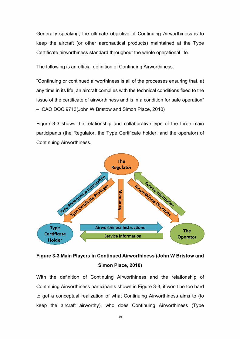
Figure 3-3 shows the relationship and collaborative type of the three main
participants (the Regulator, the Type Certificate holder, and the operator) of
Continuing Airworthiness.
Figure 3-3 Main Players in Continued Airworthiness (John W Bristow and
Simon Place, 2010)
With the definition of Continuing Airworthiness and the relationship of
Continuing Airworthiness participants shown in Figure 3-3, it won’t be too hard
to get a conceptual realization of what Continuing Airworthiness aims to (to
keep the aircraft airworthy), who does Continuing Airworthiness (Type

20
Certificate Holder, operator and competent authority – there will be
maintenance and management organisations due to further investigation), and
how to implement Continuing Airworthiness (which will be expanded upon in
the following chapters).
3.3.1 Content of Continuing Airworthiness
It’s necessary to declare in advance that, due to the limitation of time, this
project is based on the Type Certificate holder’s perspective. Consequently,
from this point on, we will mainly investigate from the Type Certificate holder’s
point of view as well.
About Continuing Airworthiness, It is clearly indicated in Part-21 that,
i. The Type Certificate holder has the responsibility to, and should have a
system to collect, investigate, and analyse data of failure, malfunctions
and defects.
ii. When an airworthiness directive has to be issued by the agency to
correct the unsafe condition, or to require the performance of an
inspection, the Type Certificate holder shall follow and execute.
iii. The Type Certificate holder shall furnish at least one set of complete
instructions for continued airworthiness.
Because of the limitation of actual conditions, it is not possible to deal with the
first and second item. Therefore, in this study, the author has narrowed his
investigation on the Continuing Airworthiness document provided to the
operator from the Type Certificate holder.

21
3.3.2 Continuing Airworthiness Instruction
In accordance with point M.A.302 (d) of Part-M (EASA, 2003), the aircraft
maintenance programme must establish compliance with instructions for
Continuing Airworthiness issued by the holders of the Type Certificate.
From this point, the Continuing Airworthiness instruction is the basis of
maintenance programme, and the maintenance programme is derived from
Continuing Airworthiness instruction.
Basically, the maintenance programme should contain check periods,
pre-flight maintenance tasks details, inspection tasks and periods
(intervals/frequencies) for parts, check periods for components, specific
structural maintenance programmes, CDCCL (Critical Design Configuration
Control Limitations), component overhaul/replacement periods, mandatory life
limitations, CMR’s (Certification Maintenance Requirements), AD’s
(Airworthiness Directives) , reliability programme details.
3.3.3 Comparison between CCAR & EASA Continuing
Airworthiness Regulation System
Continuing Airworthiness is identified and interpreted in different approaches
by CCAR and EASA regulation system.
However, the internal safety standard and the final intentional objective of
these two regulation systems are almost the same. For instance, both CCAR
and EASA regulation take MSC-3 logic as the philosophy to determine the
maintenance programme for aircrafts.
i. Regulations Structure
In CCAR, the concept of Continuing Airworthiness is not directly explained by
one single requirement. The CCAR Continuing Airworthiness system is

22
combined by several individual regulations, together with their AC (Advisory
Circular, another denomination of Acceptable Means of Certification), which
cover every main aspect of Continuing Airworthiness, including (but not only):
CCAR-121, Certification Requirements for Air Transport Operator of Large
Aircrafts
CCAR-135, Management Regulations for General Aviation Operation
CCAR-145, Certification Rules for Maintenance Organisations of Civil
Aircrafts
CCAR-43, General Rules for Maintenance and Rebuilding
In EASA, Continuing Airworthiness requirements are more structured and
systemized. All the requirements for design organizations, operator,
maintenance organizations, and Continuing Airworthiness management
organizations are all integrated in the implementing rules and its annex, Part M
(and AMC’s).
ii. Acceptable Means of Certification
In CCAR Advisory Circulars, it could be clearly realized that, which
organization the AC is based on specifically, and what that organization should
do due to the AC.
For instance, the CCAR AC-91-11, Requirements for Continuing Airworthiness
documents of aircrafts, clearly identifies that, in the type certification stage,
what kinds of documents the design organization is required to provide to
obtain the Type Certificate. Meanwhile, the contents, specifications, formality,
and schedule of these documents are identified in this AC as well.
Comparatively, EASA AMCs are not described as directly as CCAR ACs.
23
In conclusion, EASA and CCAR Continuing Airworthiness regulation system
have almost the same safety standard and philosophy (MSG-3 logic). However,
EASA’s Continuing Airworthiness system has a more structured and
systemized regulation structure than CCAR’s do. To make up this shortage,
CCAR provides more clear description to the regulations via Advisory Circulars
than EASA do with AMCs. Thus, when we develop the Continuing
Airworthiness plan in accordance with EASA requirements, CCAR ACs can be
a significant reference and supplement to the investigation.
3.4 Introduction to ATA MSG-3 Logic
Within the type design stage, the Continuing Airworthiness would be initially
established. During this period, the identification of maintenance tasks and the
prediction of maintenance intervals can be one of the most important
assignments concerning Continuing Airworthiness.
3.4.1 Development of MSG-3
The ATA (Air Transport Association) MSG-3 (Maintenance Steering Group - 3)
logic is the most widely used methodology to determine the maintenance tasks,
and to estimate the maintenance intervals before the type aircraft comes into
operation.
The very first MSG document; Handbook MSG-1 was developed by
representatives of various airlines in July 1968. It contained decision logic and
inter-airline/manufacturer procedures for developing scheduled maintenance
for the new Boeing 747 aircraft. (ATA, 2003) In 2003, the MSG-3 Revision
2003 (not the latest issued, but the highest edition available at internet) was
issued by ATA.

24
3.4.2 Mission of MSG-3
The objective of MSG-3 is to present a means for developing the scheduled
maintenance tasks and intervals which will be acceptable to the regulatory
authorities, the operators, and the manufacturers, from both safety and
economic point of view.
Before the processes of development, the scheduled maintenance tasks were
divided into two groups; scheduled tasks (at specified intervals) and
non-scheduled tasks.
In the group of scheduled tasks, it covers from the most common task, which is
lubrication and servicing to the most extreme task, which is discarding. And the
non-scheduled tasks take place as a subsequence of scheduled task, or a
functional failure, or a series of data analysis.
And the mission of MSG-3 could be divided into 4 sections; airframe systems
(including powerplant and APU’s), structural components, zonal inspections,
and L/HIRF. Each section can be used independently from other sections.
3.4.3 The Author’s Understanding about MSG-3
The following are the author’s understands of MSG-3 procedures based on his
own investigation and study.
I. MSG-3 carries out a top-to-bottom logical approach to classify the
functional failure of systems/sub-systems, components, and parts, and
then determines the maintenance tasks due to categories.
II. The input of MSG-3 is occurrence of functional failures. The applicability
of inputs is critical for the accuracy of the results.

25
III. Significant Items (including Maintenance Significant Items and
Structural Significant Items) can be emphasised in MSG-3. Hence, the
identification of significant items is significant as well.
IV. For structural maintenance, Fatigue Damage deserves more attention
in type design phase.
V. For other system/sub-systems, components, and parts, which
developed based on experience data, the collection and analysis of
data can be important.
3.5 The Continuing Airworthiness Applied on Flying Crane
Project
As described in previous sections, the methodology of author’s research is
MSG-3 logic. The output of this research is a proposed maintenance plan for
selected airframe systems and structural components of Flying Crane, which
includes maintenance tasks and intervals. And the input is the functions,
function failures, failure effects, and failure causes of the objective airframe
systems, and fatigue damage data of the objective structural components.
The required data can be provided by system reliability and maintainability
people and particular designer of each components of the Flying Crane project.
The source of author’s individual research is the results of these colleagues
during their group design phase.
Hence, it is necessary to clarify first that, what valuable data can be provided
and selected from the group design phase.

26
3.5.1 Airframe System
As previously mentioned, input is critical to aircraft maintenance developed
under MSG-3 logic. Without specific and adequate data generated in detailed
design phase, there will be nowhere to start the analysis procedure.
In the group design phase, the systems reliability and maintainability people
developed a range of analysis tools related to system functions, including FHA
(Functional Hazard Assessment), FTA (Fault Tree Analysis) and PSSA
(Preliminary System Safety Analysis) for the ice protection system and
surveillance system, as well as the FMEA (Failure Mode and Effect Analysis)
for fuel system. Among these analysis tools, FMEA provides applicable
information that can be directly adopted as the basis to develop maintenance
plan on. Thus, the fuel system was selected.
3.5.2 Structural Component
For structure design, fatigue analysis results are directly related to structural
maintenance plan.
In the Group Design Project, structure designers chose the most widely
accepted fatigue design type, Damage Tolerance Design. With this design
method, the length and growth rate of fatigue crack can be calculated, and the
structural inspection interval was suggested by the designer as well. The data
resulted from Damage Tolerance analysis is one of the most essential inputs
of MSG-3 logic.
The author had three typical structural components analyzed using MSG-3
logic. The selected structures were fuselage skin panel, fin-fuselage
attachment, and wing root joint.

27
3.6 Research to Non-destructive Tests
Within scheduled maintenance processes, Non-destructive Test (NDT) is
widely applied to discover most types of damage occurred on aircraft
structures.
Literally according to the name, Non-destructive Test is a series of inspection
techniques used to find out scratches or defaults of metallic material or
component insides without causing any damage.
Material seams (such as fatigue scratch on significant structural items) and
internal contaminants (such as entrapped water and corrosion inside the
airplane skin panel) can be revealed during scheduled maintenance tasks
using Non-destructive Tests, and then followed by maintenance activities
against those defaults.
In this section, the author will investigate and discuss seven of the most
common Non-destructive Test methods which have the possibilities to be
applied to the scheduled maintenance of aircraft structures, including Visual
Inspection, Radiographic Inspection, Ultrasonic Testing, Eddy Current Testing,
Dye Penetrant Inspection, Magnetic Particle Inspection, and Infrared
Inspection.
3.6.1 Visual Inspection
Visual Inspection is the basic and primary method among all Non-destructive
Tests. It could lead to the decision that whether other NDT is applicable.
This category could be subcategorized into General Visual Inspection (GVI)
and Detailed Visual Inspection (DVI). GVI means that an inspection is
implemented by naked eyes without any assistant tools. Oppositely, DVI is
aided by magnifiers, mirrors, and accessibility enhancement equipments such
as borescopes or introscopes.

28
Visual Inspection is the oldest and still the most widely used method of
Non-destructive Inspections because of its simplicity, quickness and economy.
Common uses:
The most common use of GVI is to find out visible fatigue scratch on external
surfaces, as well as any other type of visible scratches on accessible surfaces.
With optical aids such as borescopes and television camera, DVI is also used
to discover damage on internal surfaces or piping insides.
In addition, other advanced NDT methods can be used according to the results
from Visual Inspection.
Limitations:
The result of Visual Inspection is valid only for surfaces with good condition.
Basically, cleaning is necessary before the application of Visual Inspection.
Furthermore, de-painting, degreasing, and sandblasting can be needed in
some certain situations.
Additionally, human factor affects the results of Visual Inspection significantly.
Results can be different depending on the training level of the inspectors, the
physical and mental condition of one single inspector, the accessibility of
illumination, and the size of acceptable defect comparing to the whole
inspection area.
3.6.2 Radiographic Inspection
Industrial Radiographic Inspection includes X-ray Inspection and Gamma-ray
(ɣ-ray) Inspection. Radiography technique is used to demonstrate a shadow
image of a solid item in order to discover internal defects which are invisible to
direct eyesight.
29
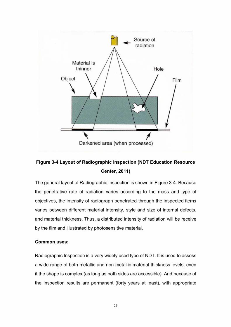
Figure 3-4 Layout of Radiographic Inspection (NDT Education Resource
Center, 2011)
The general layout of Radiographic Inspection is shown in Figure 3-4. Because
the penetrative rate of radiation varies according to the mass and type of
objectives, the intensity of radiograph penetrated through the inspected items
varies between different material intensity, style and size of internal defects,
and material thickness. Thus, a distributed intensity of radiation will be receive
by the film and illustrated by photosensitive material.
Common uses:
Radiographic Inspection is a very widely used type of NDT. It is used to assess
a wide range of both metallic and non-metallic material thickness levels, even
if the shape is complex (as long as both sides are accessible). And because of
the inspection results are permanent (forty years at least), with appropriate
30
equipments and sufficient look angles, real-time radiographic images can be
realized.
Limitations:
Both sides of the objective have to be accessible. The probability of inspection
will be reduced severely when cracks are not oriented parallel to the X-ray
beam. Radiographed marginal discontinuities require much more careful
recognization by qualified personnel comparing with gross flaws. Both X-ray
and Gamma-ray harm human-beings’ health. And the process is expensive,
and takes a lot of time.
3.6.3 Ultrasonic Testing
Ultrasonic is referred to as sound waves at frequency above 20,000 Hz. And
the range of frequencies used in Ultrasonic Testing is from less than 0.1 to
larger than 15 MHz.
Because sound wave can be reflected by the boundary of different mediums,
the ultrasonic wave will be reflected in different period and amount of energy.
This difference can be analyzed to determine the presence of internal flaw or
change on thickness.
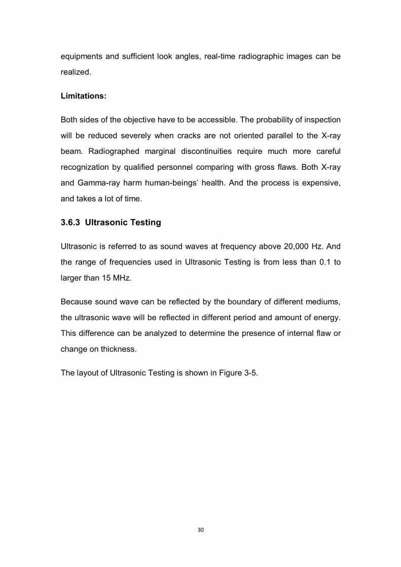
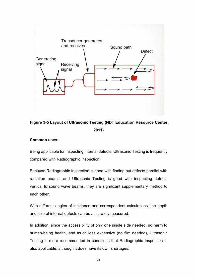
The layout of Ultrasonic Testing is shown in Figure 3-5.
31
Figure 3-5 Layout of Ultrasonic Testing (NDT Education Resource Center,
2011)
Common uses:
Being applicable for inspecting internal defects, Ultrasonic Testing is frequently
compared with Radiographic Inspection.
Because Radiographic Inspection is good with finding out defects parallel with
radiation beams, and Ultrasonic Testing is good with inspecting defects
vertical to sound wave beams, they are significant supplementary method to
each other.
With different angles of incidence and correspondent calculations, the depth
and size of internal defects can be accurately measured.
In addition, since the accessibility of only one single side needed, no harm to
human-being health, and much less expensive (no film needed), Ultrasonic
Testing is more recommended in conditions that Radiographic Inspection is
also applicable, although it does have its own shortages.
32
Limitations:
Comparing with Radiographic Inspection, Ultrasonic Testing is suitable for
thicker surfaces and defects vertical to sound beams. Higher surface condition
is required in order to avoid interfere to inspection. Operators need to be
trained more extensively than other NDT methods.
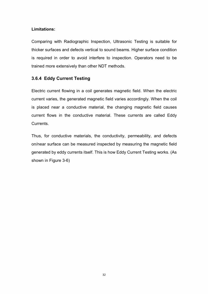
3.6.4 Eddy Current Testing
Electric current flowing in a coil generates magnetic field. When the electric
current varies, the generated magnetic field varies accordingly. When the coil
is placed near a conductive material, the changing magnetic field causes
current flows in the conductive material. These currents are called Eddy
Currents.
Thus, for conductive materials, the conductivity, permeability, and defects
on/near surface can be measured inspected by measuring the magnetic field
generated by eddy currents itself. This is how Eddy Current Testing works. (As
shown in Figure 3-6)
33
Figure 3-6 Layout of Eddy Current Testing (NDT Education Resource
Center, 2011)
Common uses:
According to the principle of Eddy Current Testing, its main usage is to inspect
properties related to conductivity changing, e.g. electrical conductivity, coating
thickness, metal sorting, and surface condition (corrosion, heat damage,
hardness).
Because the probe is not needed to touch the objective surface, Eddy Current
Testing can be used to discover surface damage in some conditions as well.
Limitations:
Obviously, Eddy Current Testing is only applicable for conductive material
such as metal. And Ferromagnetic materials require special treatment to
address magnetic permeability.
34
Because of the characteristic of magnetic field, defects lying parallel to coil
winding direction can be undetected.
The training requirements are comparatively higher.
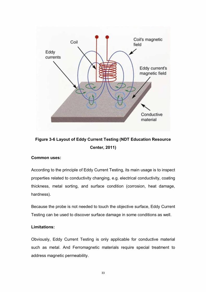
3.6.5 Dye Penetrant Inspection
Dye Penetrant Inspection (DPI) is probably the most extensively used one
among all NDT methods.
The primary principle of DPI is CAPILLARITY phenomenon. Capillarity
happens when a penetrant material bath is applied on a clean surface of an
objective. Removing excess penetrant material, the material that already
penetrated into surfaces cracks will be pulled out and dyed by the application
of Developer in the next step. Then, it is easy to detect any surface flaws under
a certain level of illumination.
Figure 3-7 "Capillarity Phenomenon" during Dye Penetrant Inspection
(NDT Education Resource Center, 2011)
35
Common uses:
Because of its effectiveness and convenience, Dye Penetrant Inspection is
widely used to locate surface cracks, especially for large areas and complex
surfaces which could be difficult for other NDT methods.
Limitations:
Only surface defects can be detected by Dye Penetrant Inspection.
The inspected surface needs to be cleaned thoroughly. In some conditions,
special cleaning processes are necessary, such as vapour de-grease and
sandblast.
Penetrant material is inflammable and harmful to human-being heath.
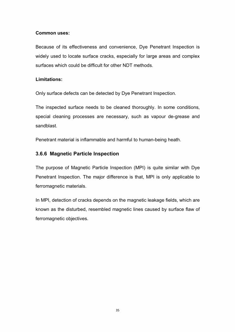
3.6.6 Magnetic Particle Inspection
The purpose of Magnetic Particle Inspection (MPI) is quite similar with Dye
Penetrant Inspection. The major difference is that, MPI is only applicable to
ferromagnetic materials.
In MPI, detection of cracks depends on the magnetic leakage fields, which are
known as the disturbed, resembled magnetic lines caused by surface flaw of
ferromagnetic objectives.
36
Figure 3-8 Layout of Magnetic Particle Inspection (NDT Education
Resource Center, 2011)
Common uses:
Magnetic Particle Inspection could be considered as an alternative of Dye
Penetrant Inspection for ferromagnetic material. However, MPI has one more
advantage, which is that defects not deep under surfaces can be discovered
by MPI.
Limitations:
There is one single limitation different than DPI, which is that the MPI is only
applicable for ferromagnetic materials.
3.6.7 Infrared Inspection
Infrared Inspection is one means of Thermal Inspections.

37
Within this type of inspection, the objective is heated by infrared radiation,
whilst its resulting temperature and/or thermal gradient is recorded and
displayed. Correlating the results with pre-settled standards, the defects can
be identified.
This mushrooming technique was firstly introduced to aviation industry in 90s
of 20th century. It has been more and more widely utilized because of obtaining
relatively extensive application, rapid procedure, large inspection area, and
visualized result.
In addition, there is no contact between infrared generator and inspected item,
and the heating can be easily controlled by adjusting the intensity of infrared
radiation.
Common uses:
Internal damage caused by external impact (especially on composite material),
fatigue scratch, corrosion (especially on internal surface), entrapped water in
the honeycomb structure or foam material of fuselage.
Limitations:
The accuracy of results can be affected by surface emissivities because of
surfaces with different materials. Surface emission has to be known before the
inspection processes. Infrared sensors with high response need cooling with
liquid nitrogen to reduce internal noise. The cost of sensors and
instrumentation is relatively high.
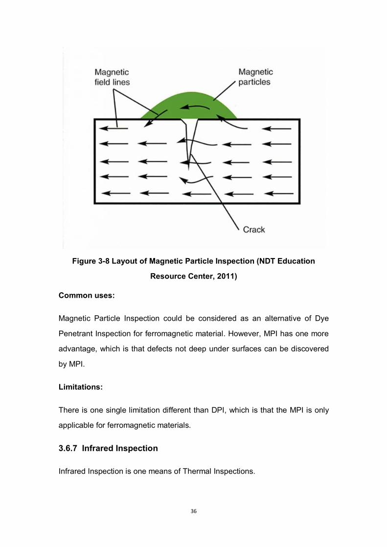
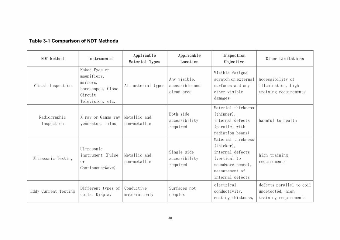
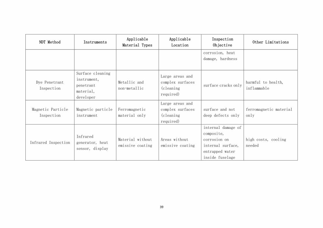
3.6.8 Comparison of Non-destructive Testing Methods
A comparison of the characteristics of different NDT methods presented above
is shown in the following Table 3-1.
38
Table 3-1 Comparison of NDT Methods
NDT Method Instruments Applicable
Material Types
Applicable
Location
Inspection
Objective Other Limitations
Visual Inspection
Naked Eyes or
magnifiers,
mirrors,
borescopes, Close
Circuit
Television, etc.
All material types
Any visible,
accessible and
clean area
Visible fatigue
scratch on external
surfaces and any
other visible
damages
Accessibility of
illumination, high
training requirements
Radiographic
Inspection
X-ray or Gamma-ray
generator, films
Metallic and
non-metallic
Both side
accessibility
required
Material thickness
(thinner),
internal defects
(parallel with
radiation beams)
harmful to health
Ultrasonic Testing
Ultrasonic
instrument (Pulse
or
Continuous-Wave)
Metallic and
non-metallic
Single side
accessibility
required
Material thickness
(thicker),
internal defects
(vertical to
soundwave beams),
measurement of
internal defects
high training
requirements
Eddy Current Testing Different types of
coils, Display
Conductive
material only
Surfaces not
complex
electrical
conductivity,
coating thickness,
defects parallel to coil
undetected, high
training requirements
39
NDT Method Instruments Applicable
Material Types
Applicable
Location
Inspection
Objective Other Limitations
corrosion, heat
damage, hardness
Dye Penetrant
Inspection
Surface cleaning
instrument,
penetrant
material,
developer
Metallic and
non-metallic
Large areas and
complex surfaces
(cleaning
required)
surface cracks only harmful to health,
inflammable
Magnetic Particle
Inspection
Magnetic particle
instrument
Ferromagnetic
material only
Large areas and
complex surfaces
(cleaning
required)
surface and not
deep defects only
ferromagnetic material
only
Infrared Inspection
Infrared
generator, heat
sensor, display
Material without
emissive coating
Areas without
emissive coating
internal damage of
composite,
corrosion on
internal surface,
entrapped water
inside fuselage
high costs, cooling
needed
40
3.7 Summary
In this chapter, the author described the concept of airworthiness, Continuing
Airworthiness, as well as the main regulatory authorities in the world, together
with the regulations they issued. Meanwhile, the regulation to comply with and
the methodology of this research were selected. And initial analysis to MSG-3
logic was presented as well. Then, the author reviewed the data related to
Continuing Airworthiness and identified those were required by this research.
In the end, a research to common Non-destructive Testing, which would be
taken as scheduled maintenance tasks, was presented.
41
4 Scheduled Maintenance Development Based On
MSG-3 Logic
In this chapter, the author applied the previously introduced MSG-3
(Maintenance Steering Group - 3) logic on the results from the Detailed Design
Phase of Flying Crane project (the Group Design Project) to propose
scheduled maintenance tasks and intervals for selected structures and
airframe system.
4.1 Obligations of Type Certificate Holders
Type Certificate Holder (TCH) is an organization that has applied and obtained
a Type Certificate of an aeronautical product. Normally, the prime
manufacturer of an aircraft, or engine, or airborne equipment is considered as
a Type Certificate Holder.
In this study, the author’s role can be considered similar to a Type Certificate
Holder’s.
Generally, from the perspective of Continuing Airworthiness, a TCH has three
fundamental obligations in the whole design and service life of an aircraft
Type.
To generate Continuing Airworthiness instructions, which are the basis
and guideline for operators to build aircraft maintenance programmes.
These instructions are supposed to consist of specifications for operation
and maintenance, interface information between main components, and
manuals for airborne equipments.
To collect and analyze feedback from operators and directives from
regulatory authority, in order to keep improving the design and
42
maintenance programme of the aircraft, as well as revising the defects and
problems detected during the aircraft’s operation.
To provide technical support to the operators for service difficulties and
mandatory corrective activities.
Scheduled maintenance is contained in Continuing Airworthiness instructions.
This work should be accomplished during the type design phase, and
submitted to the regulatory authority as one of the main supportive documents
for Type certification.
4.2 Scheduled Maintenance for Selected Structures
According to ATA MSG-3 logic, damages to aircraft structures could be caused
by three damage sources, Accidental Damage (AD), Environmental
Deterioration (ED), and Fatigue Damage (FD). Damages caused by different
damage sources should be analyzed separately using different methods and
logics.
The input of this analysis was the results from detail design phase of Flying
Crane in Group Design Project. The results included design detail, selected
material, damage tolerance data, etc. And the input included the A check and
C check intervals provided by maintainability designer in Group Design Project
as well.
4.2.1 Introduction to Selected Structural Items
In this part of research, the author selected three structural items, which had
been designed according to damage-tolerance type during GDP phase. These
items are fuselage skin panel, fin-fuselage attachment, and wing root joint,
which were designed respectively by aft fuselage, fin, and inner wing structure
designers.

43
i. Fuselage skin panel
According to the results of detail design, the skin thickness was 2.0mm
between station 19.92m and 23.5m, 1.6mm between 23.5m and 28.5m, and
1.2mm after 28.05m. The chosen material was 2024-T3 (aluminium alloy with
copper and magnesium, tempered to ultimate tensile strength of 400-427
MPa).
Figure 4-1 Aft Fuselage Skin of Flying Crane
(Jinglin Liu, Cranfield University Group Design Report, 2010)
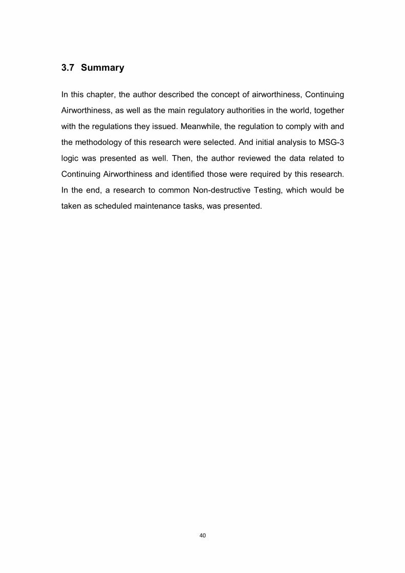
ii. Fin-fuselage attachment
The fin was designed removable to increase the maintainability and
inspectability. To satisfy the removability, the designer chose to use two bolts
to fasten the double edge lugs and at spar flanges and one bolt to fasten the
middle lug (see Figure 4-2).
The material was Ti-6Al-4V (alpha-beta titanium alloy).
44
Figure 4-2 Fin-Fuselage Attachment of Flying Crane
(Jinfeng Lv, Cranfield University Group Design Report, 2010)
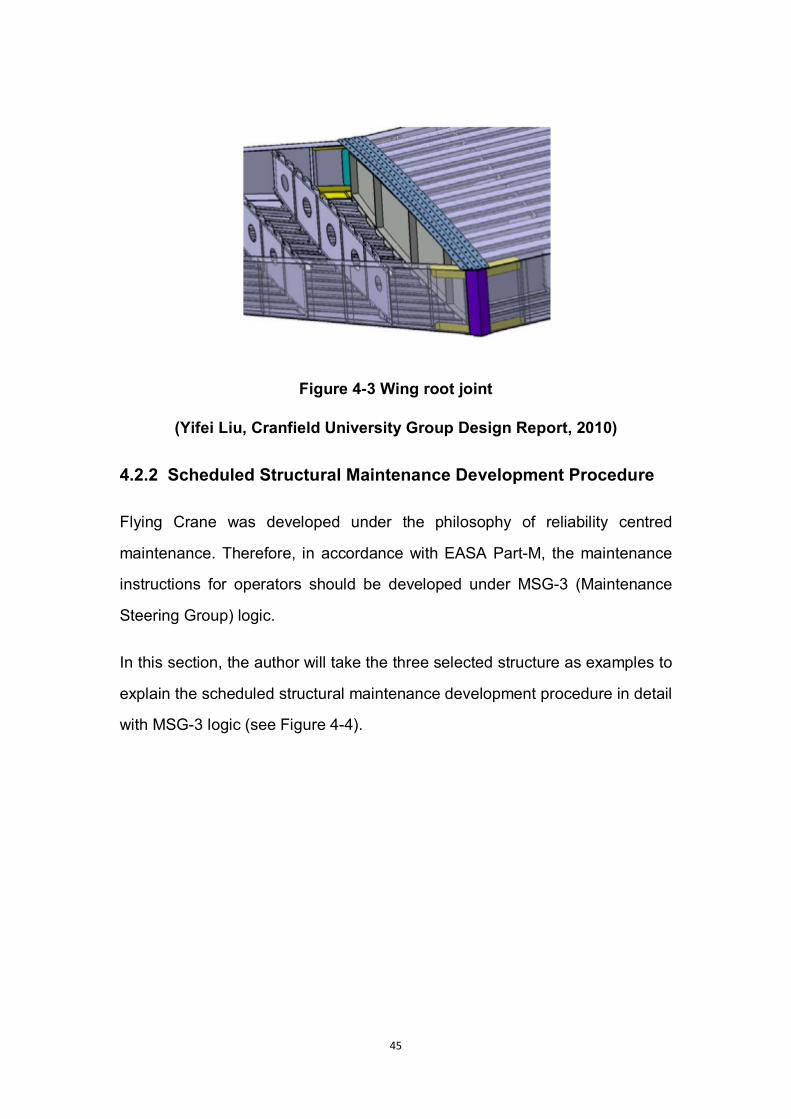
iii. Wing root joint
Wing root joint is considered as one of the most important structural areas,
especially from the perspective of Continuing Airworthiness.
The designer chose spliced plates to attach the central and inner wing
because of its light weight, reliability and inherent fail-safe feature (see Figure
4-3).
The material was Ti-6Al-4V (alpha-beta titanium alloy).
45
Figure 4-3 Wing root joint
(Yifei Liu, Cranfield University Group Design Report, 2010)
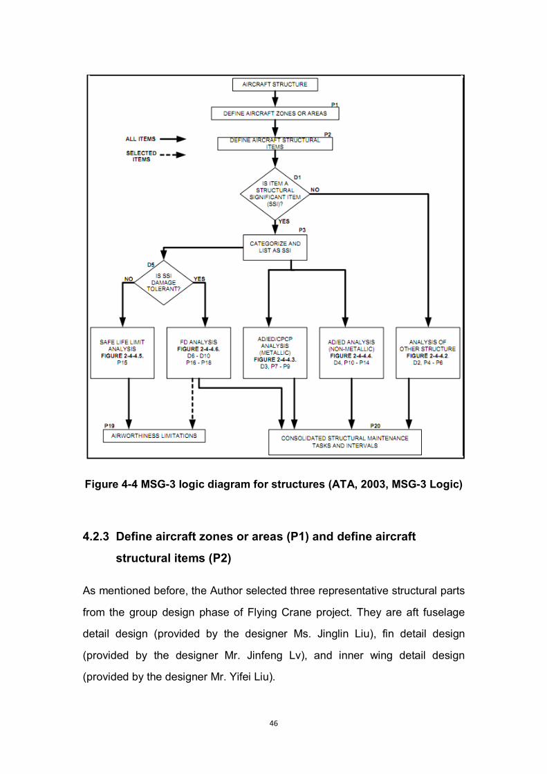
4.2.2 Scheduled Structural Maintenance Development Procedure
Flying Crane was developed under the philosophy of reliability centred
maintenance. Therefore, in accordance with EASA Part-M, the maintenance
instructions for operators should be developed under MSG-3 (Maintenance
Steering Group) logic.
In this section, the author will take the three selected structure as examples to
explain the scheduled structural maintenance development procedure in detail
with MSG-3 logic (see Figure 4-4).
46
Figure 4-4 MSG-3 logic diagram for structures (ATA, 2003, MSG-3 Logic)
4.2.3 Define aircraft zones or areas (P1) and define aircraft
structural items (P2)
As mentioned before, the Author selected three representative structural parts
from the group design phase of Flying Crane project. They are aft fuselage
detail design (provided by the designer Ms. Jinglin Liu), fin detail design
(provided by the designer Mr. Jinfeng Lv), and inner wing detail design
(provided by the designer Mr. Yifei Liu).

47
The fatigue analysis data and results of these three structures were all
available.
4.2.4 Identifying Structural Significant Items (D1)
First, it’s necessary to identify that, a Structural Significant Item (SSI) is any
detail, element or assembly, which contributes significantly to carrying flight,
ground, pressure or control loads, and whose failure could affect the structural
integrity necessary for the safety of the aircraft. (ATA MSG-3, 2003)
Fuselage skin panel is one of the most significant elements of an aircraft. With
its failure, the aerodynamic performance will be totally reversed, and the
internal components will be easily corroded and contaminated. It has
significant affect for flight safety. Thus, the fuselage skin panel is considered
as a Structural Significant Item.
The fin-fuselage attachments of Flying Crane were identified as structural
significant item for the following two reasons:
1) The fin-fuselage attachments need to undertake fore-aft, vertical, and
shear loads apply on the vertical stabilizer.
2) The fin of Flying Crane was designed removable to ensure the
maintainability and detectability.
With the failure of the attachments, the fin can be totally off the fuselage.
Wing root joint was also identified as structural significant item, because that,
without this joint, the wings can be broke and the aeroplane can be out of
control completely.
As the selected structures are all structural significant items, the next step
should be P3, Categorize and list SSI’s.
48
4.2.5 Generating Structural Significant Items List (P3)
All the three selected structural items were identified as Structural Significant
Items. The SSI’s list in this research, which can be considered as a segment of
the SSI’s list of Flying Crane aeroplane, is as follow (Table 4-1).
Table 4-1 Structural Significant Item List
Item ID SSI Name Zone Material Category
01 Fuselage Skin Panel Aft Fuselage Metallic
02 Fin-fuselage Attachment Fin Metallic
03 Wing Root Joint Inner Wing Metallic
4.2.6 AD/ED/CPCP Analysis for Metallic Structures (P7 – P9)
As all selected structures are metallic, the next procedure should be P7 – P9,
AD/ED/CPCP Analysis (see Figure 4-5).
In accordance with MSG-3 logic, in this stage, a rating system should be
utilized to rate each structural significant item in terms of susceptibility and
detectability due to each damage source. This rating system is supposed to be
applicable for the assessment of each structural significant item. And rating of
Accidental Damage, Environmental Deterioration, and Fatigue Damage should
all be included.
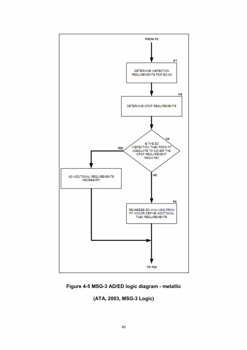
49
Figure 4-5 MSG-3 AD/ED logic diagram - metallic
(ATA, 2003, MSG-3 Logic)

50
To establish an SSI rating system is a great amount of work by both
manufacturers and airline operators based on their experience.
Because of time limitation, and lack of relevant experience data, in this study,
the author just analyzed the selected structures and listed the AD/ED
requirements to them.
Talking about Accidental Damage and Environmental Deterioration, these
types of damage sources could be understood as damage sources other than
fatigue damage during airliners’ service life. The main means of damage for
the selected structures are list in Table 4-2 below.
Table 4-2 Main Accidental Damage and Environmental Deterioration of
selected structures
Fuselage
skin panel
Foreign impact, e.g. hail, debris, and birds
Corrosion, especially corrosion on internal surface
Failed structures, e.g. fasteners, sealant
Entrapped water
Wing root joint Loose bolts
Corrosion
Fin-fuselage
attachment
Loose bolts
Corrosion
For the fuselage skin panel, physical damage caused by impact could be
detected by visual check. The check frequency, which should be established
based on experience data, could vary according to season, climate, air quality,
51
etc. Basically, visual checks on skin panel should be taken every A check at
least.
Corrosion on structures is a common problem for each item. For corrosion on
external surfaces, visual check is applicable. Corrosion on internal surface or
structures can be found with Non-Destructive Tests such as Infrared
Inspection and X-ray Inspection. The visual check for corrosion should be
taken every A check. The inspections where Non-Destructive Tests needed
are recommended to be taken every four A checks (4A check).
Rivets and sealant on skin panel can be checked visually. Welds should be
inspected with NDT. And internal bolts on fin-fuselage attachment and wing
root joint should be inspected with NDT as well. It is compatible with corrosion
checks that, visual check should be taken every A check. The inspections
where NDT needed will be taken every C check. Table 4-3 provides a
summary of the checks.
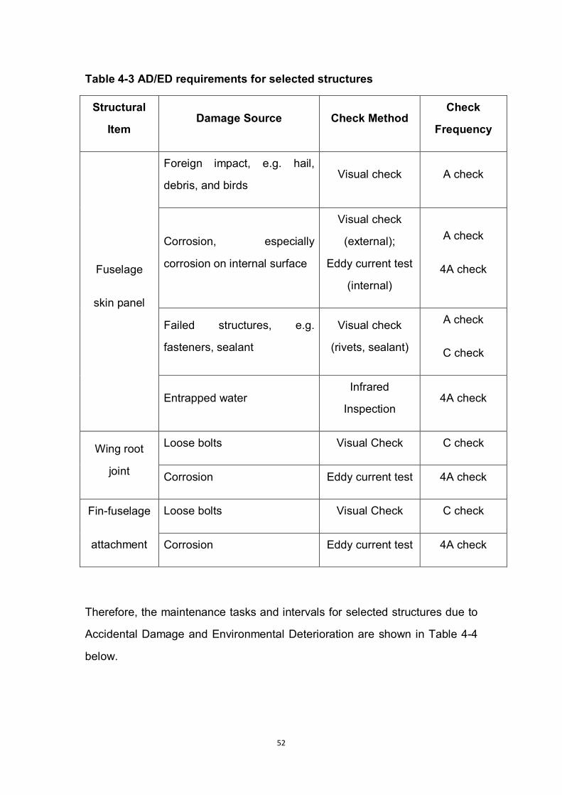
52
Table 4-3 AD/ED requirements for selected structures
Structural
Item Damage Source Check Method
Check
Frequency
Fuselage
skin panel
Foreign impact, e.g. hail,
debris, and birds Visual check A check
Corrosion, especially
corrosion on internal surface
Visual check
(external);
Eddy current test
(internal)
A check
4A check
Failed structures, e.g.
fasteners, sealant
Visual check
(rivets, sealant)
A check
C check
Entrapped water Infrared
Inspection 4A check
Wing root
joint
Loose bolts Visual Check C check
Corrosion Eddy current test 4A check
Fin-fuselage
attachment
Loose bolts Visual Check C check
Corrosion Eddy current test 4A check
Therefore, the maintenance tasks and intervals for selected structures due to
Accidental Damage and Environmental Deterioration are shown in Table 4-4
below.
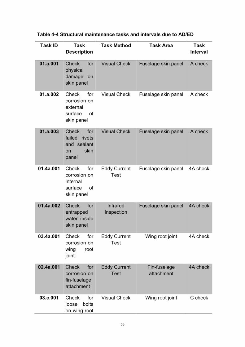
53
Table 4-4 Structural maintenance tasks and intervals due to AD/ED
Task ID Task Description
Task Method Task Area Task Interval
01.a.001 Check for physical damage on skin panel
Visual Check Fuselage skin panel A check
01.a.002 Check for corrosion on external surface of skin panel
Visual Check Fuselage skin panel A check
01.a.003 Check for failed rivets and sealant on skin panel
Visual Check Fuselage skin panel A check
01.4a.001 Check for corrosion on internal surface of skin panel
Eddy Current Test
Fuselage skin panel 4A check
01.4a.002 Check for entrapped water inside skin panel
Infrared Inspection
Fuselage skin panel 4A check
03.4a.001 Check for corrosion on wing root joint
Eddy Current Test
Wing root joint 4A check
02.4a.001 Check for corrosion on fin-fuselage attachment
Eddy Current Test
Fin-fuselage attachment
4A check
03.c.001 Check for loose bolts on wing root
Visual Check Wing root joint C check
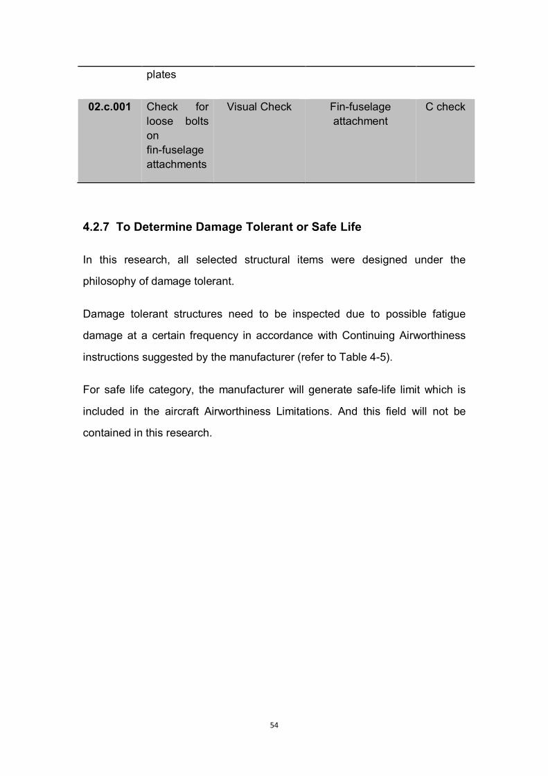
54
plates
02.c.001 Check for loose bolts on fin-fuselage attachments
Visual Check Fin-fuselage attachment
C check
4.2.7 To Determine Damage Tolerant or Safe Life
In this research, all selected structural items were designed under the
philosophy of damage tolerant.
Damage tolerant structures need to be inspected due to possible fatigue
damage at a certain frequency in accordance with Continuing Airworthiness
instructions suggested by the manufacturer (refer to Table 4-5).
For safe life category, the manufacturer will generate safe-life limit which is
included in the aircraft Airworthiness Limitations. And this field will not be
contained in this research.
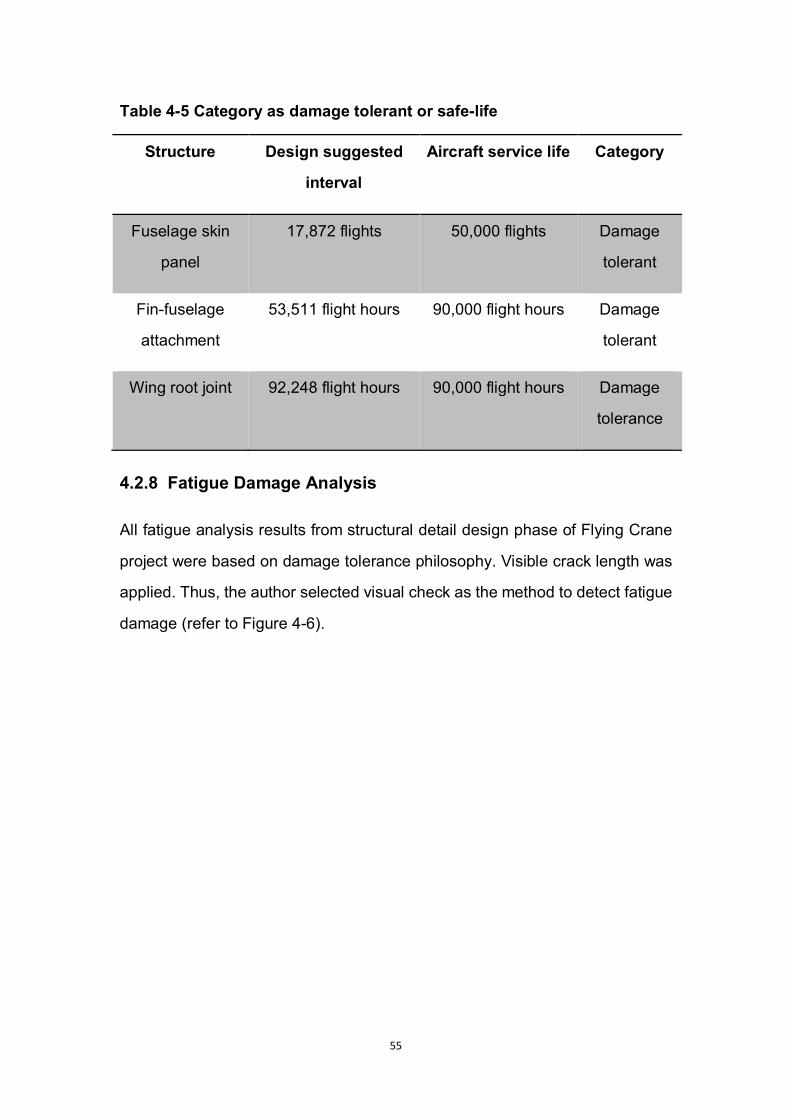
55
Table 4-5 Category as damage tolerant or safe-life
Structure Design suggested
interval
Aircraft service life Category
Fuselage skin
panel
17,872 flights 50,000 flights Damage
tolerant
Fin-fuselage
attachment
53,511 flight hours 90,000 flight hours Damage
tolerant
Wing root joint 92,248 flight hours 90,000 flight hours Damage
tolerance
4.2.8 Fatigue Damage Analysis
All fatigue analysis results from structural detail design phase of Flying Crane
project were based on damage tolerance philosophy. Visible crack length was
applied. Thus, the author selected visual check as the method to detect fatigue
damage (refer to Figure 4-6).

56
Figure 4-6 MSG-3 Fatigue Damage logic diagram (ATA, 2003, MSG-3
Logic)
57
For fuselage skin panel, the designer suggested inspection interval was 4,468
flights. Because Flying Crane aircraft is designed aimed at Chinese domestic
market, the author assumed the average operating duration per flight is three
hours, which is compatible to the airline between Beijing and Guangzhou, two
of the biggest cities in domestic China (Official website of Civil Aviation
Administration of China, 2010).
Thus, to convert flights to flight hours, the suggested inspection interval of
fuselage skin panel equals to 4,468 flights multiple 3 hours per flight equals to
13,404 flight hours. Since the C check interval of Flying Crane is 6,000 flight
hours, the inspection to fatigue damage on fuselage skin panel should be
taken every two C checks during operation.
For the fin-fuselage attachment, the designer suggested inspection interval
was 17,837 flight hours. Because a safety factor of 4 was applied in the detail
design phase, it is acceptable to extend the inspection interval to 18,000 flight
hours, which equals to three C check intervals.
For the wing root joint, the inspection interval was 92,248 flight hours, which
already exceeded the length of aircraft service life. So in this research, there
was no maintenance task related to fatigue damage for wing root joint. Table
4-6 provides a summary of the maintenance tasks and intervals due to fatigue
damage.
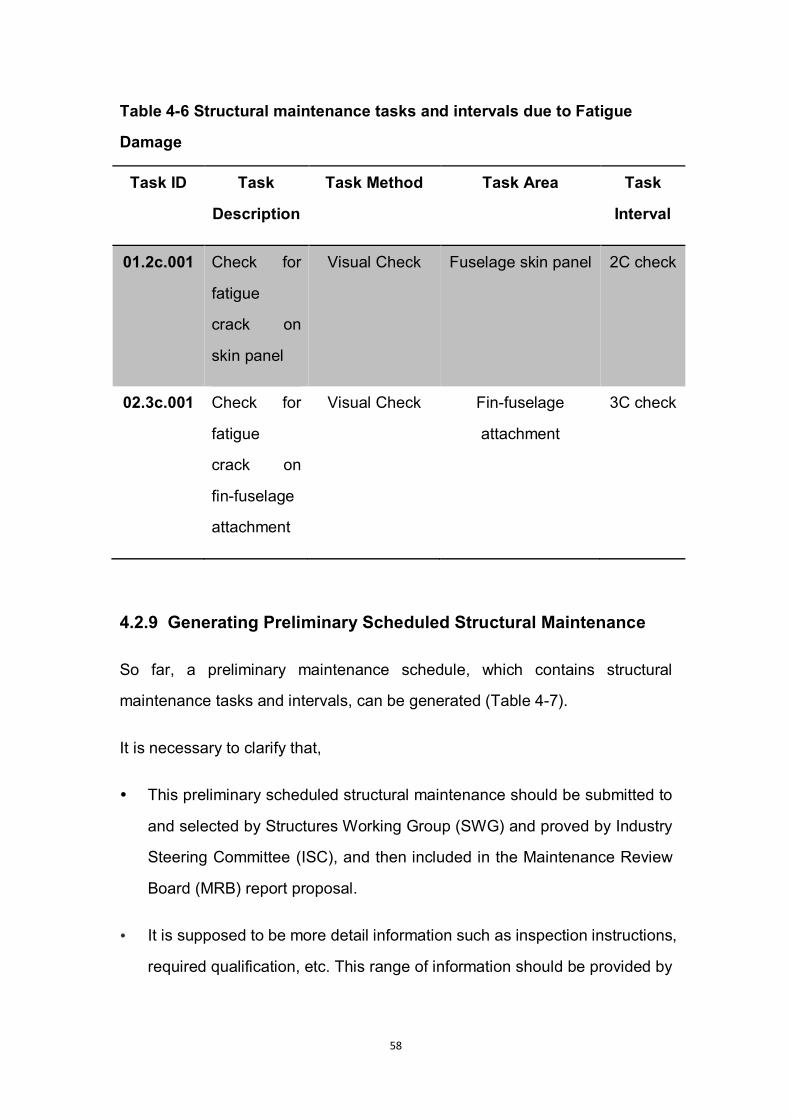
58
Table 4-6 Structural maintenance tasks and intervals due to Fatigue
Damage
Task ID Task
Description
Task Method Task Area Task
Interval
01.2c.001 Check for
fatigue
crack on
skin panel
Visual Check Fuselage skin panel 2C check
02.3c.001 Check for
fatigue
crack on
fin-fuselage
attachment
Visual Check Fin-fuselage
attachment
3C check
4.2.9 Generating Preliminary Scheduled Structural Maintenance
So far, a preliminary maintenance schedule, which contains structural
maintenance tasks and intervals, can be generated (Table 4-7).
It is necessary to clarify that,
This preliminary scheduled structural maintenance should be submitted to
and selected by Structures Working Group (SWG) and proved by Industry
Steering Committee (ISC), and then included in the Maintenance Review
Board (MRB) report proposal.
It is supposed to be more detail information such as inspection instructions,
required qualification, etc. This range of information should be provided by

59
design department, maintenance department, and quality department of
the manufacturer in the real life.

60
Table 4-7 Scheduled Maintenance for Selected Structures
Task ID Task
Description
Task Method Task Area Task
Interval
01.a.001 Check for
physical
damage on
skin panel
Visual Check Fuselage skin panel A check
01.a.002 Check for
corrosion on
external
surface of
skin panel
Visual Check Fuselage skin panel A check
01.a.003 Check for
failed rivets
and sealant
on skin
panel
Visual Check Fuselage skin panel A check
01.4a.001 Check for
corrosion on
internal
surface of
skin panel
Eddy Current
Test
Fuselage skin panel 4A check
01.4a.002 Check for
entrapped
water inside
skin panel
Infrared
Inspection
Fuselage skin panel 4A check
03.4a.001 Check for
corrosion on
wing root
Eddy Current
Test
Wing root joint 4A check

61
joint
02.4a.001 Check for
corrosion on
fin-fuselage
attachment
Eddy Current
Test
Fin-fuselage
attachment
4A check
03.c.001 Check for
loose bolts
on wing root
plates
Visual Check Wing root joint C check
02.c.001 Check for
loose bolts
on
fin-fuselage
attachments
Visual Check Fin-fuselage
attachment
C check
01.2c.001 Check for
fatigue
crack on
skin panel
Visual Check Fuselage skin panel 2C check
02.3c.001 Check for
fatigue
crack on
fin-fuselage
attachment
Visual Check Fin-fuselage
attachment
3C check
4.3 Scheduled Maintenance for Selected System
In MSG-3 logic, airframe system analysis needs more supportive data from
system designers and reliability department than structures.
62
For each item under analysis, the following must be identified in advance:
functions, functional failures, failure effects, and failure causes.
For this reason, in this study, the author selected fuel system as the example
to implement MSG-3 system analysis because of the availability of such
necessary data.
4.3.1 Introduction to Fuel System
The fuel system of Flying Crane was developed by Mr Zhaoang Meng during
the detail design phase. It has four main sub-systems, which are engine/APU
feed system, refuel/defuel system, vent/scavenge system, and fuel
management system.
Inside each wing, there are three fuel tanks, which are inner tank, outer tank
and surge tank. Among them, inner tanks and outer tanks are fuel tanks
providing fuel directly to the engine and APU. And surge tanks are
pressurization tanks, which is used to keep balance of the aircraft. (Zhaoang
Meng, Cranfield University Group Design Report, 2010)
The necessary input of this section, functions, functional failures, failure effects,
and failure causes, was delivered in the means of Failure Mode and Effects
Analysis (FMEA), which was developed with the assist from maintainability
designer, Mr Wangfeng Yang (seen in Figure 4-7).
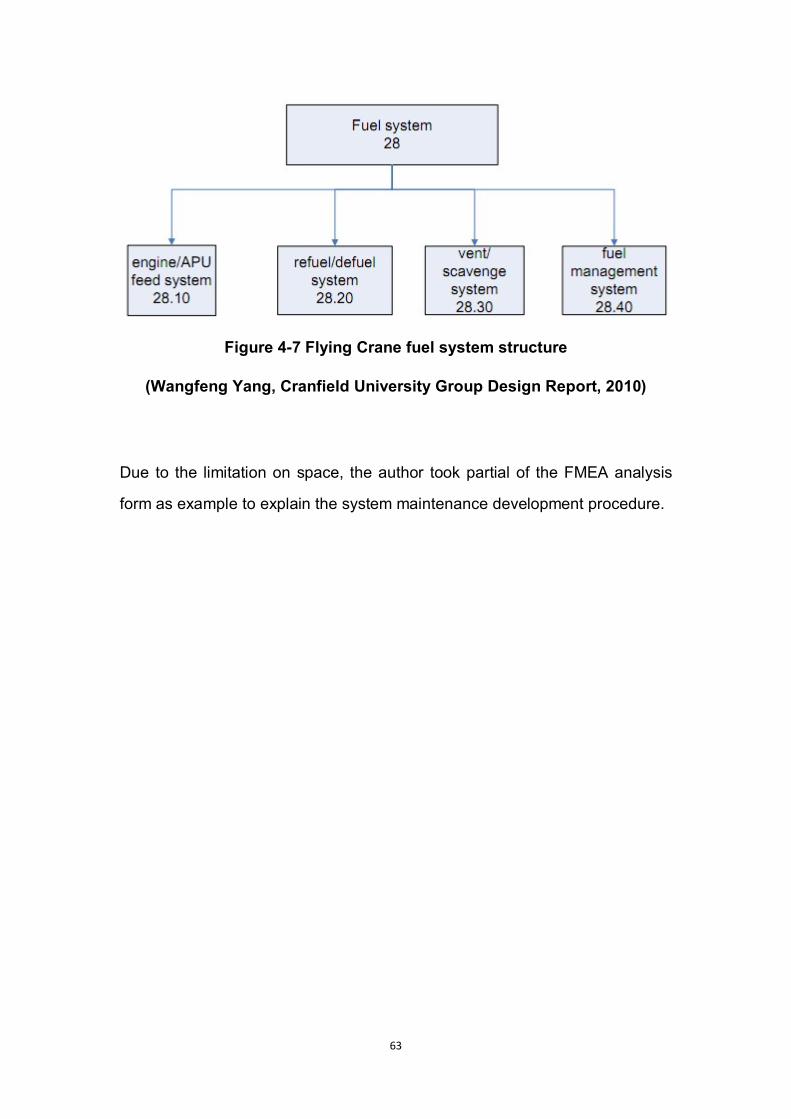
63
Figure 4-7 Flying Crane fuel system structure
(Wangfeng Yang, Cranfield University Group Design Report, 2010)
Due to the limitation on space, the author took partial of the FMEA analysis
form as example to explain the system maintenance development procedure.
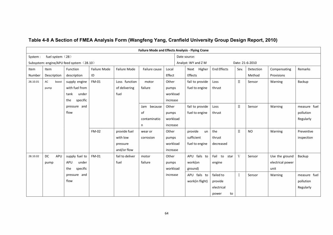
64
Table 4-8 A Section of FMEA Analysis Form (Wangfeng Yang, Cranfield University Group Design Report, 2010)
Failure Mode and Effects Analysis - Flying Crane
System : fuel system(28)
Subsystem: engine/APU feed system(28.10)
Date source:
Analyst: WY and Z M Date: 21-6-2010
Item
Number
Item
Description
Function
description
Failure Mode
ID
Failure Mode Failure cause Local
Effect
Next Higher
Effects
End Effects Sev. Detection
Method
Compensating
Provisions
Remarks
28.10.01
AC boost
pump
supply engine
with fuel from
tank under
the specific
pressure and
flow
FM-01
Loss function
of delivering
fuel
motor
failure
Other
pumps
workload
increase
fail to provide
fuel to engine
Loss
thrust
Ⅱ Sensor Warning Backup
Jam because
of
contaminatio
n
Other
pumps
workload
increase
fail to provide
fuel to engine
Loss
thrust
Ⅱ Sensor Warning measure fuel
pollution
Regularly
FM-02
provide fuel
with low
pressure
and/or flow
wear or
corrosion
Other
pumps
workload
increase
provide un
sufficient
fuel to engine
the
thrust
decreased
Ⅱ NO Warning Preventive
inspection
28.10.02
DC APU
pump
supply fuel to
APU under
the specific
pressure and
flow
FM-01
fail to deliver
fuel
motor
failure
Other
pumps
workload
increase
APU fails to
work(on
ground)
Fail to star
engine
Ⅴ Sensor Use the ground
electrical power
unit
Backup
APU fails to
work(in flight)
failed to
provide
electrical
power to
Ⅰ Sensor Warning measure fuel
pollution
Regularly
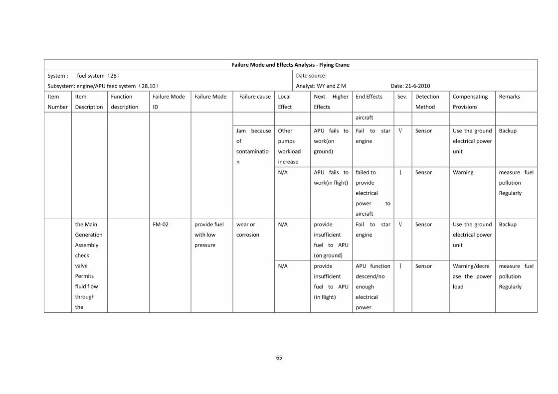
65
Failure Mode and Effects Analysis - Flying Crane
System : fuel system(28)
Subsystem: engine/APU feed system(28.10)
Date source:
Analyst: WY and Z M Date: 21-6-2010
Item
Number
Item
Description
Function
description
Failure Mode
ID
Failure Mode Failure cause Local
Effect
Next Higher
Effects
End Effects Sev. Detection
Method
Compensating
Provisions
Remarks
aircraft
Jam because
of
contaminatio
n
Other
pumps
workload
increase
APU fails to
work(on
ground)
Fail to star
engine
Ⅴ Sensor Use the ground
electrical power
unit
Backup
N/A APU fails to
work(in flight)
failed to
provide
electrical
power to
aircraft
Ⅰ Sensor Warning measure fuel
pollution
Regularly
the Main
Generation
Assembly
check
valve
Permits
fluid flow
through
the
FM-02
provide fuel
with low
pressure
wear or
corrosion
N/A provide
insufficient
fuel to APU
(on ground)
Fail to star
engine
Ⅴ Sensor Use the ground
electrical power
unit
Backup
N/A provide
insufficient
fuel to APU
(in flight)
APU function
descend/no
enough
electrical
power
Ⅰ Sensor Warning/decre
ase the power
load
measure fuel
pollution
Regularly

66
4.3.2 Maintenance Significant Items Selection
Before the MSG-3 logic applied on system items, Maintenance Significant
Items (MSI) should be identified.
To select maintenance significant items, the whole aircraft, as well as each
system and sub-system, should be divided into major functional areas, until all
replaceable items identified.
And then, those items would be judged from four aspects, which are
detectability, safety affect, operational impact, and economic impact. Because
fuel system is an airframe system closely related to flight safety and economy,
all listed items were identified as Maintenance Significant Items.
At last, the candidate MSI list needs to be submitted to and get approval from
Industry Steering Committee in the real industry.
This part of work was done in GDP phase and partly shown in table 4-9
Table 4-9 Failure Effect Category of Selected Maintenance Significant
Items
Maintenance Significant Item
Functional failure Failure effect
category
AC boost pump Loss function of delivering fuel 5
AC boost pump provide fuel with low pressure and/or flow 5
DC APU pump fail to deliver fuel (on ground) 6
DC APU pump fail to deliver fuel (in flight) 5
DC APU pump provide fuel with low pressure (on ground) 6
DC APU pump provide fuel with low pressure (in flight) 5

67
4.3.3 Analysis Procedure
To prepare for the actual analysis procedure, for each Maintenance Significant
Item, the functions, functional failures, failure effects, and failure causes should
be identified clearly.
Generally, this range of information can be delivered within Failure Mode and
Effects Analysis (FMEA).
Table 4-8 was a really practical style of FMEA. It listed every potential
functional failure for each function, and clearly identified each functional
failure’s effects on three levels, which will be quite helpful and convenient in
the analysis procedure.
The analysis itself has two levels. Level 1 is to categorize each functional
failure by their failure effects. And level 2 is to determine what task applicable
for each functional failure.
4.3.4 Category of Failure Effects (First Level)
In the following paragraphs, the author will analyse each item in table 4-8
through MSG-3 logic (see Figure 4-8 and Figure 4-9).
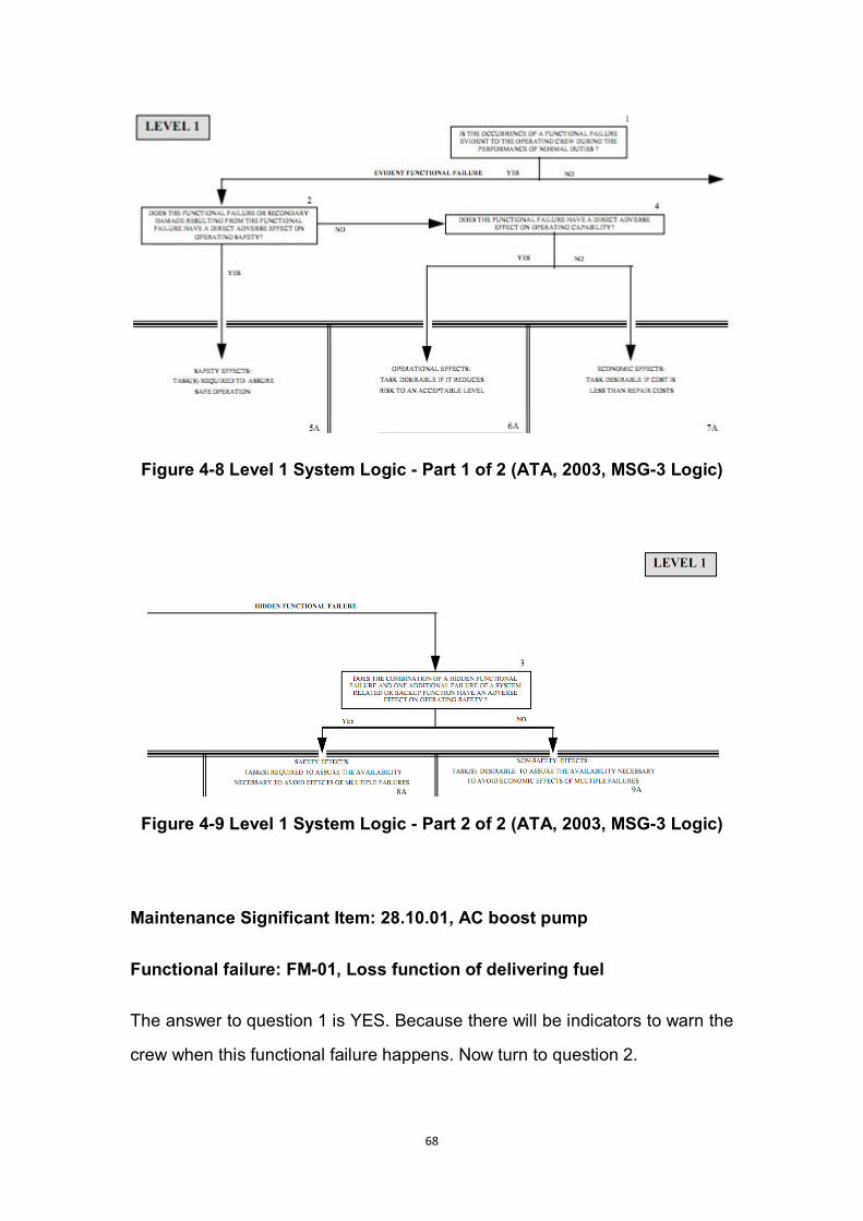
68
Figure 4-8 Level 1 System Logic - Part 1 of 2 (ATA, 2003, MSG-3 Logic)
Figure 4-9 Level 1 System Logic - Part 2 of 2 (ATA, 2003, MSG-3 Logic)
Maintenance Significant Item: 28.10.01, AC boost pump
Functional failure: FM-01, Loss function of delivering fuel
The answer to question 1 is YES. Because there will be indicators to warn the
crew when this functional failure happens. Now turn to question 2.
69
The answer to question 2 is YES. Loss of fuel delivery will lead to loss of
engine thrust. And the severity of this functional failure is II, hazardous, which
means large adverse effects will be committed.
Thus, the functional failure, “loss function of delivering fuel”, was categorized
as Category 5, “Safety Effects”.
Functional failure: FM-02, provide fuel with low pressure and/or flow
With the same analysis routine, this functional failure was categorized as
Category 5, “Safety Effects”.
Maintenance Significant Item: 28.10.02, DC APU pump
Functional failure: FM-01, fail to deliver fuel
When this failure happens on ground, it is evident to the crew. It has no
adverse effect on safety, but adverse effect on operating capability. So it is
categorized as Category 6, “Operational Effects”.
Quite differently, when this failure happens in flight, although it is still evident to
the crew, it has great adverse effects on safety because of lacking electrical
power provided. So it is categorized as Category 5, “Safety Effects”.
Functional failure: FM-02, provide fuel with low pressure
Compatible with FM-01, two situations should be considered.
When this failure happens on ground, it is evident to the crew. And it has no
adverse effect on safety, but adverse effect on operating capability. So it is
categorized as Category 6, “Operational Effects”.
When this failure happens in flight, although it is still evident to the crew, it has
great adverse effects on safety because of lacking electrical power provided.
So it is categorized as Category 5, “Safety Effects”.
70
4.3.5 Tasks Development (Category 5, Second Level)
The category 5 is functional failures which have evident safety effects. For
those functional failures related to safety, all questions should be asked.
The functional failure of loss function of delivering fuel, AC boost pump was
taken as example.
This functional failure has two possible causes, which are motor failure and
contamination jam.
Refer to Figure 4-10, Question 5A: YES. For motor failure, scheduled
lubrication and servicing would be helpful to maintain the motor at a good
working condition. For contamination jam, a clearance for all related fuel tubing
will help reduce the risk of this functional failure.

71
Figure 4-10 Functional Failures Categorized as Evident Safety Effects
(ATA, 2003, MSG-3 Logic)
Proposed tasks:
i. Pump motor servicing
ii. Fuel tubing cleaning

72
Question 5B: YES. Figure 4-11, which is called P-F curve, demonstrates what
happens in an item’s service life. It is a widely accepted concept in
reliability-centred maintenance. As shown in P-F curve, a functional failure
happens at point F, and it had been detectable since point P. So in the period
between point P and F, the potential failure can be found out by an inspection
or functional check.
Proposed tasks:
iii. Functional check the AC boost pump
Figure 4-11 The P-F curve (John Moubray, 1997)
Question 5C: YES. For finished products such as AC boost pump, it is
necessary to uninstall them after a certain period of usage and send them back
to the work shop to restore them into a high working condition.
Proposed tasks:
iv. Alternate AC boost pumps for restoration
Question 5D: YES. After a long period of usage, there will be unrecoverable
internal wear within the pump. So in this condition, a discard is needed.
Proposed tasks:
73
v. Discard the AC boost pump
Question 5E: YES. In this step, as this is a category related to safety, every
task should be taken unless it is totally covered by another, or several of them
can be combined into one with all original purpose. Among the tasks proposed
above, the fifth task, discard the AC boost pump, can be combined with the
forth task, alternate AC boost pumps for restoration. Because when the pumps
back to the work shop, the supplier would determine its availability. If a discard
is needed, it will happen together with restoration works. So there’s no need to
discard the pump when maintaining the system.
The same procedure was applied on the other three functional failures which
categorized as evident safety effects. Table 4-10 shows the proposed
maintenance tasks.
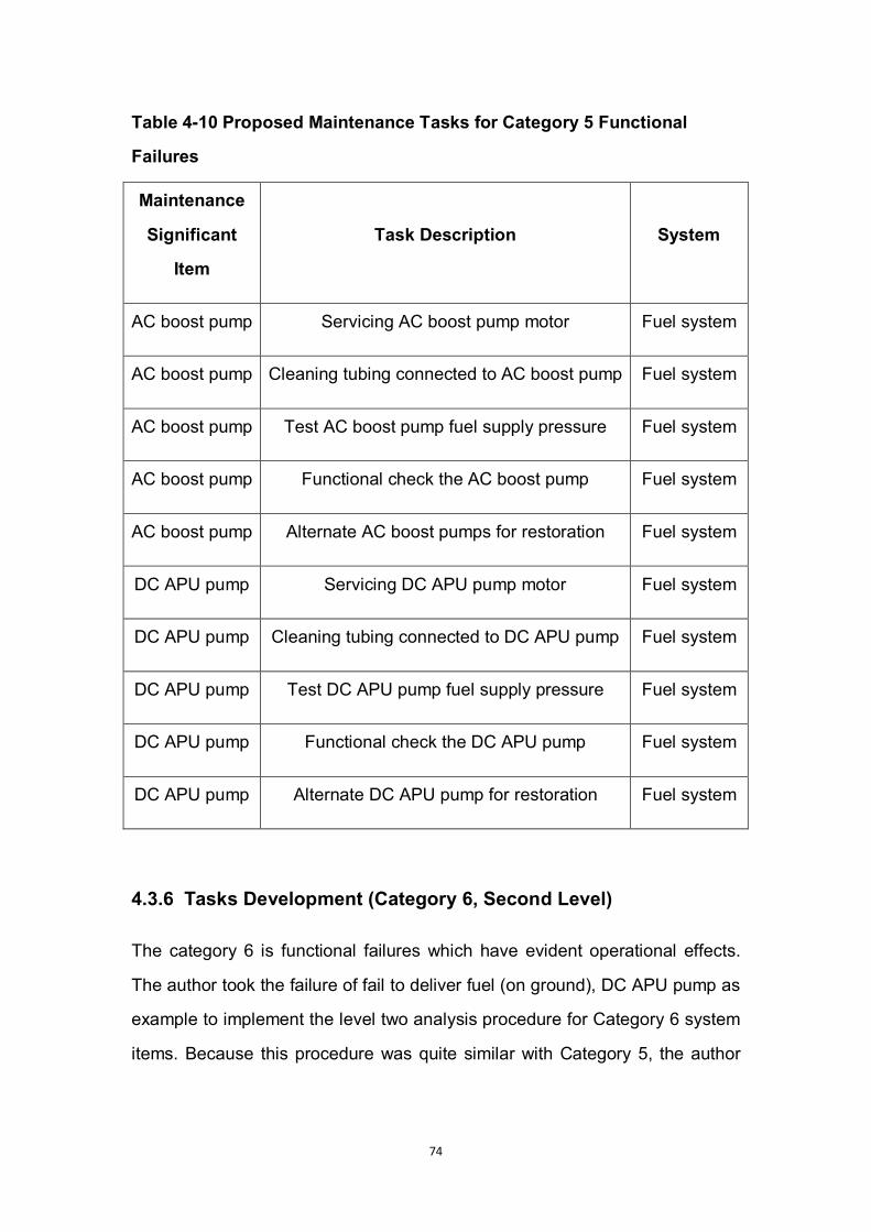
74
Table 4-10 Proposed Maintenance Tasks for Category 5 Functional
Failures
Maintenance
Significant
Item
Task Description System
AC boost pump Servicing AC boost pump motor Fuel system
AC boost pump Cleaning tubing connected to AC boost pump Fuel system
AC boost pump Test AC boost pump fuel supply pressure Fuel system
AC boost pump Functional check the AC boost pump Fuel system
AC boost pump Alternate AC boost pumps for restoration Fuel system
DC APU pump Servicing DC APU pump motor Fuel system
DC APU pump Cleaning tubing connected to DC APU pump Fuel system
DC APU pump Test DC APU pump fuel supply pressure Fuel system
DC APU pump Functional check the DC APU pump Fuel system
DC APU pump Alternate DC APU pump for restoration Fuel system
4.3.6 Tasks Development (Category 6, Second Level)
The category 6 is functional failures which have evident operational effects.
The author took the failure of fail to deliver fuel (on ground), DC APU pump as
example to implement the level two analysis procedure for Category 6 system
items. Because this procedure was quite similar with Category 5, the author
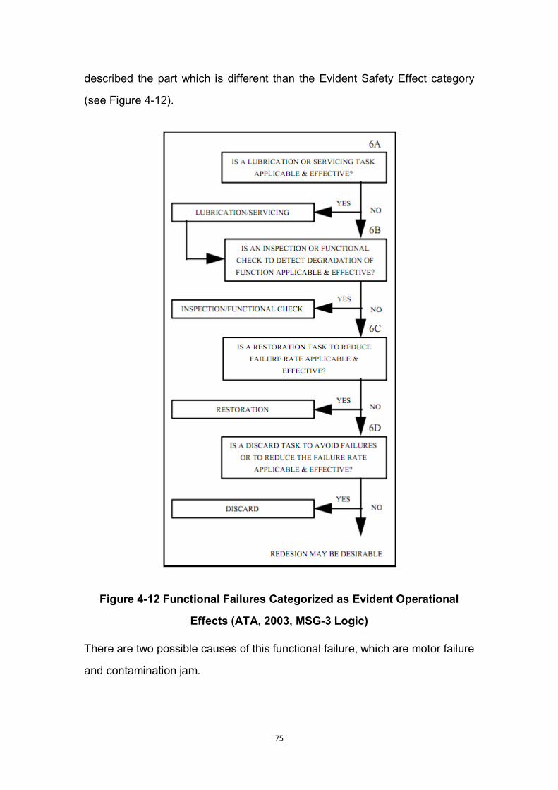
75
described the part which is different than the Evident Safety Effect category
(see Figure 4-12).
Figure 4-12 Functional Failures Categorized as Evident Operational
Effects (ATA, 2003, MSG-3 Logic)
There are two possible causes of this functional failure, which are motor failure
and contamination jam.
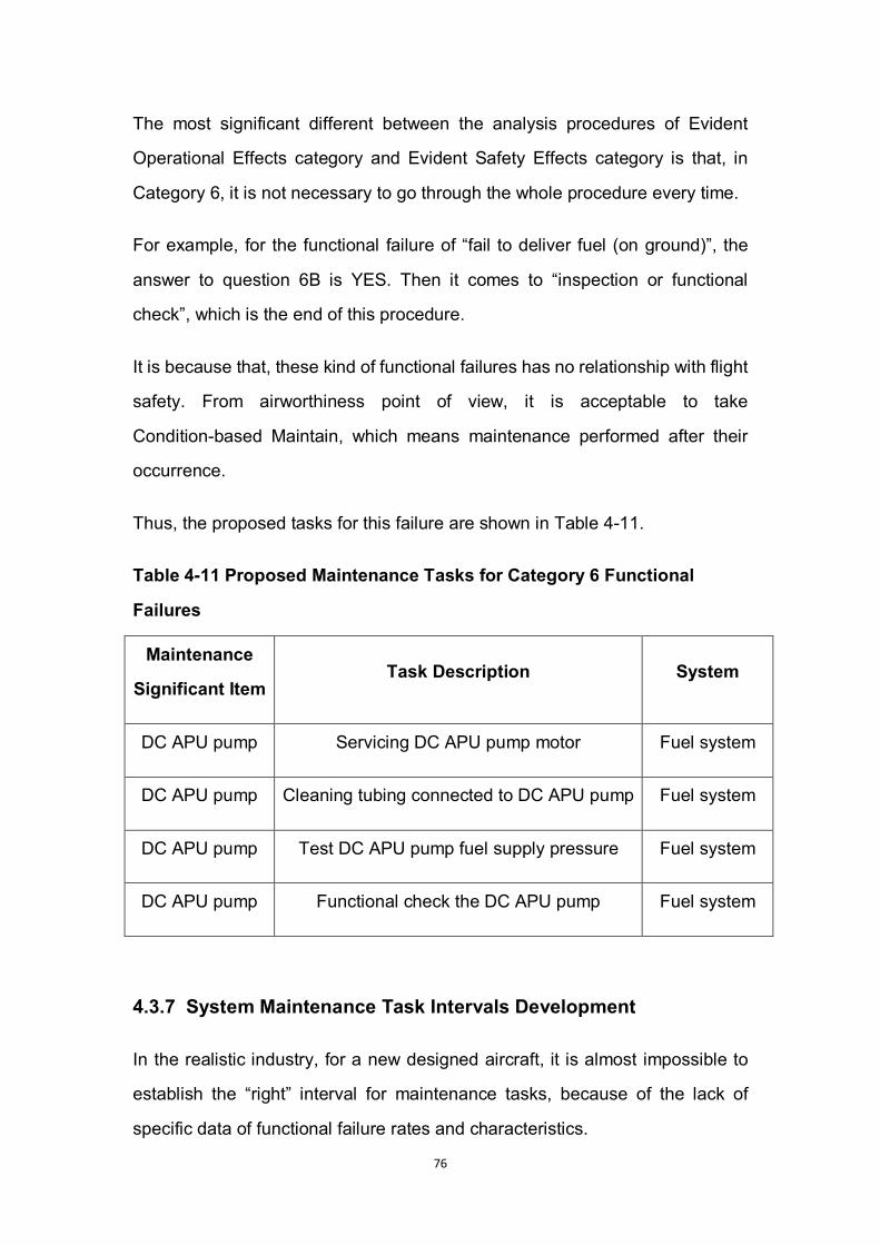
76
The most significant different between the analysis procedures of Evident
Operational Effects category and Evident Safety Effects category is that, in
Category 6, it is not necessary to go through the whole procedure every time.
For example, for the functional failure of “fail to deliver fuel (on ground)”, the
answer to question 6B is YES. Then it comes to “inspection or functional
check”, which is the end of this procedure.
It is because that, these kind of functional failures has no relationship with flight
safety. From airworthiness point of view, it is acceptable to take
Condition-based Maintain, which means maintenance performed after their
occurrence.
Thus, the proposed tasks for this failure are shown in Table 4-11.
Table 4-11 Proposed Maintenance Tasks for Category 6 Functional
Failures
Maintenance
Significant Item Task Description System
DC APU pump Servicing DC APU pump motor Fuel system
DC APU pump Cleaning tubing connected to DC APU pump Fuel system
DC APU pump Test DC APU pump fuel supply pressure Fuel system
DC APU pump Functional check the DC APU pump Fuel system
4.3.7 System Maintenance Task Intervals Development
In the realistic industry, for a new designed aircraft, it is almost impossible to
establish the “right” interval for maintenance tasks, because of the lack of
specific data of functional failure rates and characteristics.
77
Basically, in the type design and certificate phase, intervals for system
maintenance tasks are developed based on service experiences data
collected from comparative systems, components, and aircrafts.
From Continuing Airworthiness’ perspective, for the consideration of flight
safety, the recommendation of “shorten the initial interval, then extend it
gradually” will be given to the manufacturers and maintenance organizations,
especially relevant experience data is inaccessible.
There are three main methods to determine maintenance task intervals in
nowadays aviation industry.
For finished products such as pumps and valves in fuel system, the suggested
Mean Time Between Failure (MTBF) should be provided by product suppliers
to help determine maintenance task intervals.
Another method to determine maintenance interval is manufacturer’s
experiment and engineering analysis. And relative record and data should be
submitted to the competent authority together with the results.
The third method is make development based on experience data from similar
aircraft types in service. But, even for one single aircraft, the maintenance
programme could vary dramatically from different periods in its service life. For
one single type, different airlines could have quite different maintenance plans
due to different maintenance ability and operational circumstances.
For the reasons described above, the author did not make the predictive
maintenance intervals for airframe systems. The author hopes in the future
research in this field, there could be an individual research topic, which is to
determine system maintenance intervals with reliability-centred maintenance
theory.

78
4.4 Continuing Airworthiness Instructions
The scheduled maintenance tasks and intervals for systems and structures is
contained in the Maintenance Review Board Report (MRBR). MRBR is one of
the documents related to Continuing Airworthiness, submitted by type design
organizations and proved by regulatory authorities like EASA.
Other than MRBR, these documents include Aircraft Flight Manual (AFM),
Airworthiness Limitation Items (ALI), Certification Maintenance Requirement
(CMR), and Main Minimum Equipment List (MMEL).
This collection of documents is defined as Continuing Airworthiness
Instructions for type certification.
4.4.1 Organizations of Continuing Airworthiness instructions
Development
In the realistic industry, any of Continuing Airworthiness instructions is not
developed or determined by any single organization. They can be checked and
revised times and times by different types of organizations assembled to
control and support the development procedure.
Taking the maintenance schedule as example, all maintenance tasks and
intervals should be developed in associate with the Industry Steering
Committee (ISC) and Maintenance Working Group (MWG).
The members of ISC include representative from manufacturer and operators.
This organization is considered as the leader or guide for maintenance
development procedure. It accounts for work related to policy, management,
plan, final approval, and contact with regulatory authority.
On the other hand, the MWG’s, which consists of specialist representatives
from operators, manufacture, and regulatory authority, are much more like
79
supportive organizations providing supportive information such as technical
data, experiential recommendations, engineering analysis, which shall be
contained into the final report presented to regulatory authority.
4.4.2 Proposed Continuing Airworthiness Instructions of Flying
Crane
As an initial form of a part of Continuing Airworthiness instructions, the
scheduled maintenance developed by the author includes proposed predictive
maintenance tasks and intervals for three structural items (fuselage skin panel,
fin-fuselage attachment, and wing root joint) and one airframe system
(propulsion and fuel system) based on design data of Flying Crane project,
which is the Group Design Project of Aircraft Design Programme in academic
year 2010 (see Table 4-12).
Due to the limitation on time and space, lack of experiential data sources, and
limited results from detailed design phase, the author were not able to make
this research into a very specific level. Therefore, in the sixth chapter, the
author gave his own suggestion to future study.
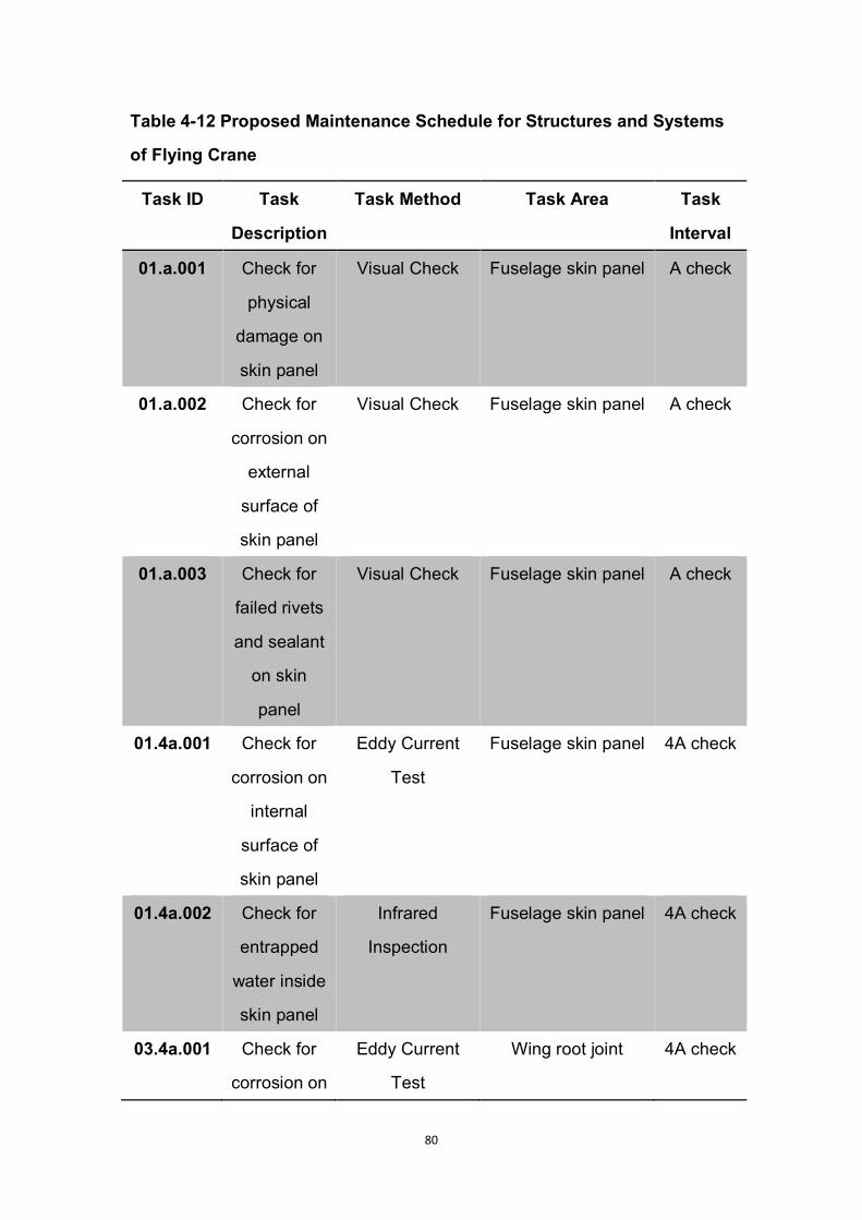
80
Table 4-12 Proposed Maintenance Schedule for Structures and Systems
of Flying Crane
Task ID Task
Description
Task Method Task Area Task
Interval
01.a.001 Check for
physical
damage on
skin panel
Visual Check Fuselage skin panel A check
01.a.002 Check for
corrosion on
external
surface of
skin panel
Visual Check Fuselage skin panel A check
01.a.003 Check for
failed rivets
and sealant
on skin
panel
Visual Check Fuselage skin panel A check
01.4a.001 Check for
corrosion on
internal
surface of
skin panel
Eddy Current
Test
Fuselage skin panel 4A check
01.4a.002 Check for
entrapped
water inside
skin panel
Infrared
Inspection
Fuselage skin panel 4A check
03.4a.001 Check for
corrosion on
Eddy Current
Test
Wing root joint 4A check
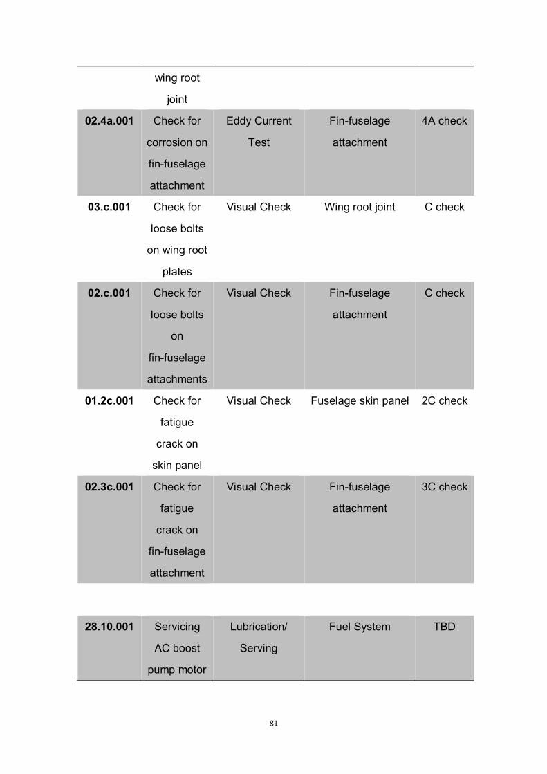
81
wing root
joint
02.4a.001 Check for
corrosion on
fin-fuselage
attachment
Eddy Current
Test
Fin-fuselage
attachment
4A check
03.c.001 Check for
loose bolts
on wing root
plates
Visual Check Wing root joint C check
02.c.001 Check for
loose bolts
on
fin-fuselage
attachments
Visual Check Fin-fuselage
attachment
C check
01.2c.001 Check for
fatigue
crack on
skin panel
Visual Check Fuselage skin panel 2C check
02.3c.001 Check for
fatigue
crack on
fin-fuselage
attachment
Visual Check Fin-fuselage
attachment
3C check
28.10.001 Servicing
AC boost
pump motor
Lubrication/
Serving
Fuel System TBD
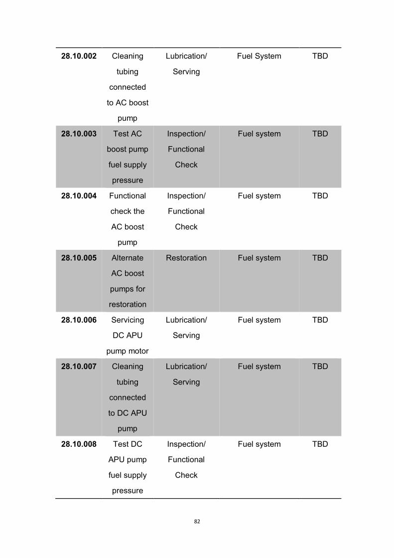
82
28.10.002 Cleaning
tubing
connected
to AC boost
pump
Lubrication/
Serving
Fuel System TBD
28.10.003 Test AC
boost pump
fuel supply
pressure
Inspection/
Functional
Check
Fuel system TBD
28.10.004 Functional
check the
AC boost
pump
Inspection/
Functional
Check
Fuel system TBD
28.10.005 Alternate
AC boost
pumps for
restoration
Restoration Fuel system TBD
28.10.006 Servicing
DC APU
pump motor
Lubrication/
Serving
Fuel system TBD
28.10.007 Cleaning
tubing
connected
to DC APU
pump
Lubrication/
Serving
Fuel system TBD
28.10.008 Test DC
APU pump
fuel supply
pressure
Inspection/
Functional
Check
Fuel system TBD

83
28.10.009 Functional
check the
DC APU
pump
Inspection/
Functional
Check
Fuel system TBD
28.10.010 Alternate
DC APU
pump for
restoration
Restoration Fuel system TBD
Notes: A check = 600 Flight Hours
C check = 20 Months or 6,000 Flight Hours
84
5 Selection of Chinese Maintenance Organizations
As the target market of Flying Crane aircraft is Mainland China, the Flying
Crane was supposed to be operated by Chinese domestic airline companies.
And the Continuing Airworthiness of Flying Crane was supposed to be
maintained by qualified Chinese domestic aircraft maintenance organizations
as well.
In this chapter, the author introduced the responsibilities of maintenance
organizations, and the criteria to select maintenance organizations for Flying
Crane aircraft.
5.1 The Role of Maintenance Organizations
A qualified and certified Maintenance Organization is supposed to have
adequate capability and correct qualification to maintain aircrafts and aircraft
components in accordance with Continuing Airworthiness instructions from the
manufacturer.
The business scope of maintenance organizations includes inspection, repair,
modification, overhaul, line maintenance, and other maintenance tasks
required by operators and authorized by competent authority (see Figure 5-1).
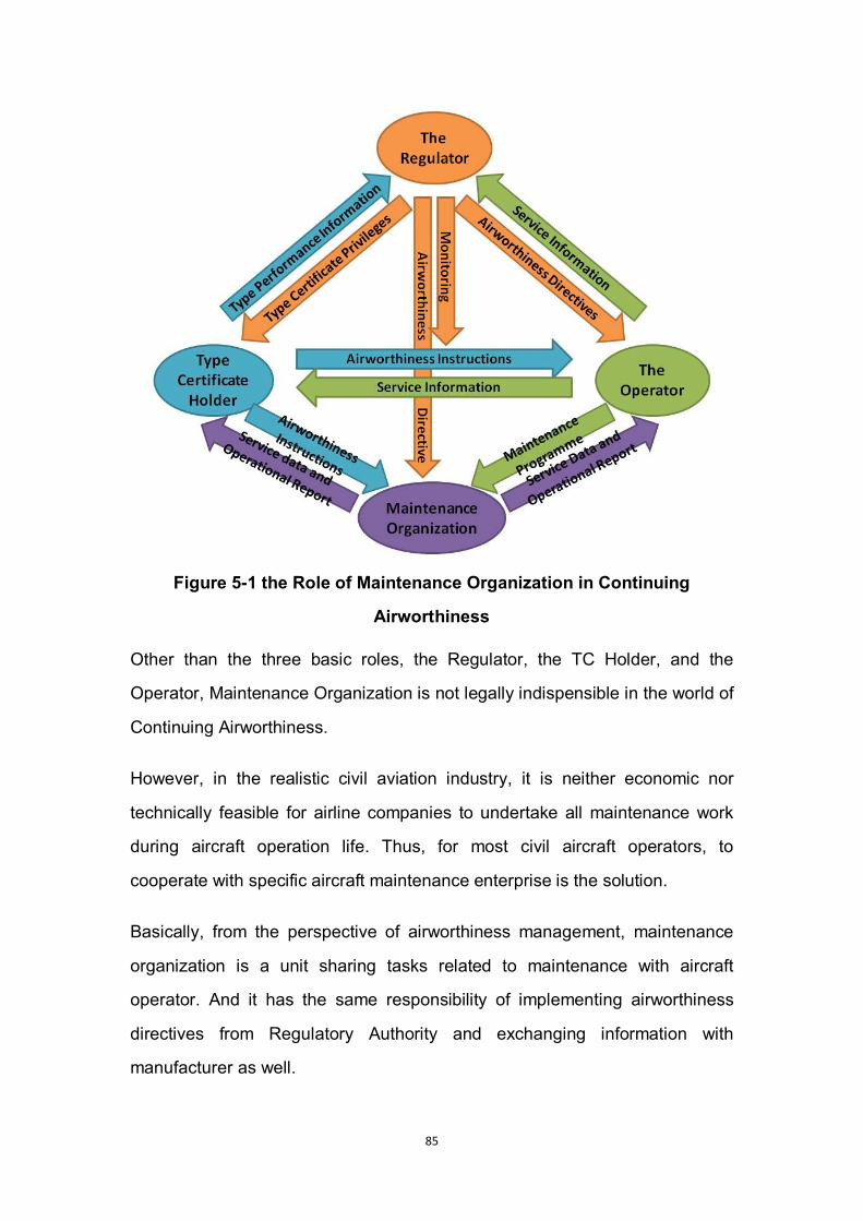
85
Figure 5-1 the Role of Maintenance Organization in Continuing
Airworthiness
Other than the three basic roles, the Regulator, the TC Holder, and the
Operator, Maintenance Organization is not legally indispensible in the world of
Continuing Airworthiness.
However, in the realistic civil aviation industry, it is neither economic nor
technically feasible for airline companies to undertake all maintenance work
during aircraft operation life. Thus, for most civil aircraft operators, to
cooperate with specific aircraft maintenance enterprise is the solution.
Basically, from the perspective of airworthiness management, maintenance
organization is a unit sharing tasks related to maintenance with aircraft
operator. And it has the same responsibility of implementing airworthiness
directives from Regulatory Authority and exchanging information with
manufacturer as well.

86
The responsibilities of maintenance organization include:
To strictly follow every certified maintenance programme issued by
operator and manufacturer;
To implement every airworthiness directive issued by Regulatory Authority;
To record any inaccuracy, deficiency, and redundancy of maintenance
programme discovered during practical operations, and give feedback to
the operator and manufacturer;
5.2 Selection Criteria
5.2.1 Maintenance Approval Class and Rating
According to Part-145, the scope of organization’s work is defined and
classified by the approval classes and ratings granted by competent authority.
The scope declines from Category A to Category D. Meanwhile, Category A is
partitioned into Base and Line maintenance.
For instance, the 4C check for fuselage and engine overhaul have to be
undertaken in maintenance organizations with Category A classes and ratings.
But for A check, a Category C is applicable.
5.2.2 Hangar Capacity
Larger hangar capacity assures higher efficiency during parallel processing.
But the demand of large hangar capacity depends on the fleet size of the
specific operator.
87
5.2.3 Market Performance and Experience
Market is a good tool to measure the capability of an enterprise. So it is
significant to choose maintenance organizations with comparatively higher
market share.
In addition, different types of aircrafts have different structure characteristic,
system layout, and engine size. So the experience of maintaining aircrafts on
the comparative level with Flying Crane (e.g. Boeing 737 and Airbus A320) is
another important factor.
5.2.4 Technical Requirements
In the maintenance plan proposed in Chapter 4, the scheduled maintenance
had contained A check, 4A check, C check, 2C check, and 3C check. Due to
different maintenance intervals, the according maintenance tasks had different
technical requirements. From economic and operational perspective,
maintenance organizations with different technical level should be selected for
different maintenance tasks.
5.2.5 Accessibility
For shorter interval checks, such as A Checks, the location of the selected
maintenance organization should not be far from most often used airport.
5.3 Selecting Maintenance Organizations in China
Even during 2007 and 2008, in which the global financial crisis went the most
seriously, a rapid increase was remained in civil aviation market of China.
Along with the development of civil aviation, the aviation maintenance industry
is experiencing a fast growth as well.
In Chapter 4, the author developed a series of scheduled maintenance tasks in
different check intervals. In the following paragraphs, the author would
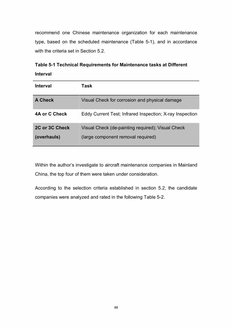
88
recommend one Chinese maintenance organization for each maintenance
type, based on the scheduled maintenance (Table 5-1), and in accordance
with the criteria set in Section 5.2.
Table 5-1 Technical Requirements for Maintenance tasks at Different
Interval
Interval Task
A Check Visual Check for corrosion and physical damage
4A or C Check Eddy Current Test; Infrared Inspection; X-ray Inspection
2C or 3C Check
(overhauls)
Visual Check (de-painting required); Visual Check
(large component removal required)
Within the author’s investigate to aircraft maintenance companies in Mainland
China, the top four of them were taken under consideration.
According to the selection criteria established in section 5.2, the candidate
companies were analyzed and rated in the following Table 5-2.
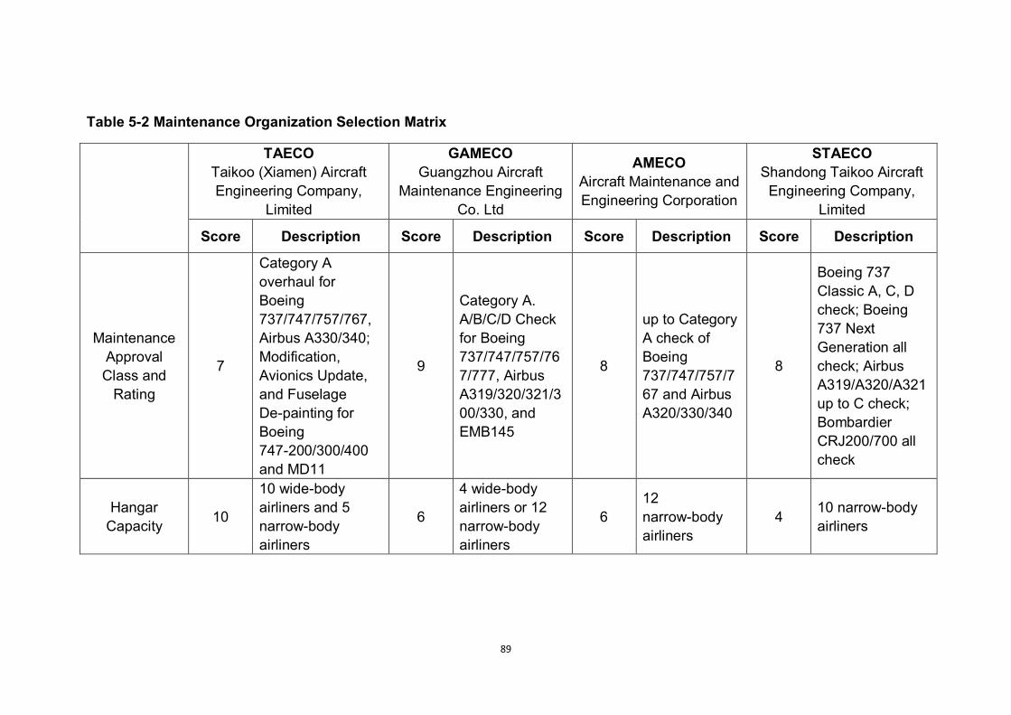
89
Table 5-2 Maintenance Organization Selection Matrix
TAECO Taikoo (Xiamen) Aircraft Engineering Company,
Limited
GAMECO Guangzhou Aircraft
Maintenance Engineering Co. Ltd
AMECO Aircraft Maintenance and Engineering Corporation
STAECO Shandong Taikoo Aircraft
Engineering Company, Limited
Score Description Score Description Score Description Score Description
Maintenance Approval Class and
Rating
7
Category A overhaul for Boeing 737/747/757/767, Airbus A330/340; Modification, Avionics Update, and Fuselage De-painting for Boeing 747-200/300/400 and MD11
9
Category A. A/B/C/D Check for Boeing 737/747/757/767/777, Airbus A319/320/321/300/330, and EMB145
8
up to Category A check of Boeing 737/747/757/767 and Airbus A320/330/340
8
Boeing 737 Classic A, C, D check; Boeing 737 Next Generation all check; Airbus A319/A320/A321 up to C check; Bombardier CRJ200/700 all check
Hangar Capacity 10
10 wide-body airliners and 5 narrow-body airliners
6
4 wide-body airliners or 12 narrow-body airliners
6 12 narrow-body airliners
4 10 narrow-body airliners

90
TAECO Taikoo (Xiamen) Aircraft Engineering Company,
Limited
GAMECO Guangzhou Aircraft
Maintenance Engineering Co. Ltd
AMECO Aircraft Maintenance and Engineering Corporation
STAECO Shandong Taikoo Aircraft
Engineering Company, Limited
Score Description Score Description Score Description Score Description
Market Performance
and Experience
7
focused on large airliner maintenance, relatively lack of experience about narrow body aircraft maintenance
7
experienced in maintaining narrow-body airliners
9
experienced in maintaining narrow-body airliners
5
experience in maintaining narrow-body airliners only
Technical Requirements 10 All requirements
satisfied 10 All requirements satisfied 10
All requirements satisfied
10 All requirements satisfied
Accessibility 7
Located in Xiamen City, Fujian Province, which is on the coast of Southeast China
10
Located in Guangzhou City, Guangdong Province, South China
10
Located in Beijing, the Capital of China
5 Located in Jinan, Shandong, Mid-east China
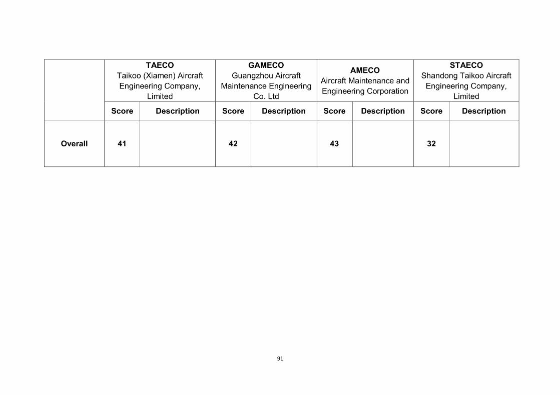
91
TAECO Taikoo (Xiamen) Aircraft Engineering Company,
Limited
GAMECO Guangzhou Aircraft
Maintenance Engineering Co. Ltd
AMECO Aircraft Maintenance and Engineering Corporation
STAECO Shandong Taikoo Aircraft
Engineering Company, Limited
Score Description Score Description Score Description Score Description
Overall 41 42 43 32

92
Refer to the overall ratings, STAECO got the lowest score 32, which suggested
that it did not obtain enough advantages compared with other candidate
companies within this assessment rules.
The other three companies got almost the same score, which indicated that
they all satisfied the maintenance demands of Flying Crane.
Based on their own advantages, they were designated respectively as
maintenance organizations for overhauls, mid-term maintenance and
short-term maintenance for the following reasons.
For maintenance organization for overhauls, large hangar capacity is
necessary to ensure parallel working in order to keep process delay and
time costs at a relatively low level.
For maintenance organization for short-term maintenance, quickness and
efficiency are priorities to be concerned. So the company located at the
position with the highest accessibility was selected.
For mid-term maintenance, both of above two points have to be
considered, and the choice of the company with the richest experience
with narrow-body airline maintenance ensured that potential significant
failures could be discovered at a relatively high possibility.
The following is further information concerning the selected maintenance
organizations.
i. Maintenance Organization for Overhauls
Organization: Taikoo Aircraft Engineering Company, Limited (TAECO)
Organization Introduction: Taikoo Aircraft Engineering Co. Ltd (TAECO), which
is located in Xiamen City, Fujian Province (Southeast China), was initially

93
launched in 1993. It has become one of the largest and most professional
aircraft maintenance centre in the world.
Approval Class and Rating: Category A overhaul for Boeing 737/747/757/767,
Airbus A330/340; Modification, Avionics Update, and Fuselage De-painting for
Boeing 747-200/300/400 and MD11.
Hangar Capacity: simultaneously 10 wide-body airliners and 5 narrow-body
airliners
(TAECO, 2010)
Advantages: the largest hangar capacity in China; high technical level.
Disadvantages: comparatively lack of experienced in narrow-body aircraft
maintenance,
ii. Maintenance Organization for Mid-term Maintenance
Organization: Guangzhou Aircraft Maintenance Engineering Co. Ltd
(GAMECO)
Organization Introduction: GAMECO is located in Guangzhou City,
Guangdong Province (South China), firstly launched in 1989. Its main
customer, China Southern Airline, is the biggest airline company in China
Approval Class and Rating: Category A. A/B/C/D Check for Boeing
737/747/757/767/777, Airbus A319/320/321/300/330, and EMB145
Hangar Capacity: simultaneously 4 wide-body airliners or 12 narrow-body
airliners
(GAMECO, 2010)

94
Advantages: Largest Hangar other than TAECO; experienced in maintaining
narrow-body airliners;
iii. Maintenance Organization for Short-term Maintenance
Organization: Aircraft Maintenance and Engineering Corporation (AMECO)
Organization Introduction: AMECO is located in Beijing, China, firstly launched
in 1989, based on the Capital International Airfield of Beijing.
Approval class and rating: up to Category A check of Boeing 737/747/757/767
and Airbus A320/330/340
Hangar Capacity: simultaneously 12 narrow-body airliners
(AMECO, 2010)
Advantages: experienced in maintaining narrow-body airliners
95
6 Conclusion and Further Work
This is a research into Continuing Airworthiness from the perspective of a TC
Holder (manufacturer), based on the detailed design of Flying Crane aircrafts.
6.1 Research Findings
In this research, two aspects of Continuing Airworthiness were investigated,
including maintenance programme and maintenance organization.
For maintenance programme, the author selected the MSG-3 logic, which is
the most accepted and widely used method to plan scheduled maintenance
during aircraft Type design phase.
With MSG-3 logic, the author developed the maintenance plan for three
structural components (fuselage skin panel, wing root joint, and fin-fuselage
attachment) and one airframe system (fuel system) based on results from the
Group Design Project in academic year 2010-2011.
For maintenance organization, the author investigated the Chinese domestic
aircraft maintenance market, and selected applicable maintenance
organizations technically and economically.
Within the research, the following findings have been achieved:
In MSG-3 logic, the ultimate aim is to ensure flight safety, whilst both
technology and economy are under consideration. And the key to
Continuing Airworthiness is to balance the technology and economy as
well.
The technical basis of MSG-3 analysis is Reliability-centred Maintenance
and Damage Tolerance, which related to airframe system maintenance
and structure maintenance respectively.
96
Experience, including design experience, operational experience,
maintenance experience, plays a role no less importance than calculation
and analysis. Because the preliminary maintenance plan is proposed on
the basis of service experience, and approved by ISC (Industry Steering
Committee), which consists of a group of experienced specialist from
manufacturers, operators, and Regulatory Authority.
MSG-3 logic is mainly focused on components with high level of
importance. As in both system and structure analysis, to identify
Maintenance/Structural Significant Items is the very first step.
Maintenance programmes vary from operator to operator, fleet to fleet,
aircraft to aircraft. Even one single aircraft could have different
maintenance programme due to different service years. Thus, the
maintenance plan developed by manufacture is just a proposal. The
specific operators should build their own maintenance programmes due to
the one proposed by manufacturers.
Compared with other types of system safety analysis, FMEA (Failure Mode
and Effect Analysis) is the most applicable as the input of MSG-3 system
analysis. Because it contains all of the Function, Functional Failure, Failure
Cause, and Failure Effect of a system or sub-system.
The interval of maintenance task against functional failure can be resulted
from MTBF (Mean Time Between Failures). In addition, the inherent MTBF
of a system could be calculated by designer, and MTBF for procured
products should be provided by the supplier.
For a new type of aircraft, the initially proposed intervals of maintenance
tasks are recommended to be comparatively shorter. The interval could be
extended along with the increased service period.

97
6.2 Aim and Objectives Achieved
As set at the beginning of this research, the aim of research was to prove one
means of compliance to satisfy the EASA requirements related to Continuing
Airworthiness by applying the airworthiness requirements and the
methodology of MSG-3 logic on Flying Crane.
The author believes the aim of research has been achieved by the
achievement of the objectives as following:
Objective: To investigate current Continuing Airworthiness regulations,
including EASA airworthiness requirements (as the main regulation to
comply with) and Chinese CCAR airworthiness regulations (as an
important reference and supplement to the research)
Achievement: Achieved. The author did investigate EASA requirements
and CCAR regulations related to Continuing Airworthiness, and made
comparison between those regulations. In addition, EASA requirements
were applied along the whole research process.
Objective: To investigate the main analysis methodology of reliability and
maintainability, including Damage Tolerance and Failure Mode and Effect
Analysis (FMEA);
Achievement: Achieved. With the procedure of structure and system
maintenance development, the results of both Damage Tolerance and
FMEA were applied to MSG-3 logic.
Objective: To analyze the data resulted from Group Design Project using
MSG-3 logic to produce a set of Continuing Airworthiness instructions, for
the operator and maintenance organization of the aircraft, from the design
organization’s perspective;

98
Achievement: Mostly Achieved. At the beginning of this research, three
airframe systems and three structural items were planned to be analyzed
with MSG-3 logic and resulted in Continuing Airworthiness instructions. But
at present, there is only one system analyzed. The reason was that, the
author was not able to realize the practical differences between different
types of reliability tools such as Faulty Tree Assessment and FMEA.
During the process of research, only FMEA delivered sufficient information
for MSG-3 analysis. And due to the time limitation, only the fuel system,
which contained a complete FMEA analysis form, was analyzed.
Objective: To develop Continuing Airworthiness instructions for operator to
compose maintenance programme for Flying Crane aircraft, including
maintenance tasks and intervals for the selected airframe systems and
structural components;
Achievement: Mostly Achieved. But for the same reason with the previous
objective, the proposed maintenance programme was not as much as
initially supposed.
To identify applicable maintenance organizations in China mainland for
Flying Crane aircraft in accordance with both EASA and CCAR
requirements.
Achievement: Achieved. Three of Chinese domestic aircraft maintenance
organizations were identified due to different maintenance types.
6.3 Limitation of MSG-3 Logic
As previously mentioned, experience, including design experience, operational
experience, maintenance experience, plays an extremely important role during
the MSG-3 logic.

99
In the reality of industrial applications, the preliminary maintenance plan is
approved by ISC based on their industrial experience, and certified by
specialist employed by competent authority based on their experience as well.
That means the maintenance plan is largely proposed from experience,
approved from experience, and certified from experience.
Indeed, this is actually reasonable because of the unpredictability of failure and
damage. However, in this situation, it is really impracticable for theoretical
research.
6.4 Recommendation for Further Work
6.4.1 Required Data to Implement MSG-3 Logic
Thanks to the effects of GDP teams, in this research, most of the required data
for MSG-3 logic was available by the end of GDP phase. The available data
includes:
FMEA (Failure Mode and Effect Analysis) of selected system;
Damage Tolerance analysis results of selected structures (Design life and
suggested inspection intervals); and
Intervals of A Check and C Check
In addition, in the future research related to Continuing Airworthiness and
scheduled maintenance, it will be really helpful with the provision of the
following data:
MTBF (Mean Time Between Failure) of the same system with FMEA
available; and
Statistical data of Accidental Damage and Environmental Deterioration on
selected structures.

100
6.4.2 Further Research Related to MSG-3
As previously discussed, due to limitation of theoretical research, further
research focused on MSG-3 logic itself might be impracticable or meaningless.
However, inspirited from this research, the author recommended two areas of
further research related to MSG-3:
i. The Rating System for Structures
During MSG-3 structure analysis, to identify the maintenance tasks and
intervals due to Accidental Damage and Environmental Deterioration, it is
necessary to rate the possibility of damage and detectability.
ii. Service Data Collection System
According to airworthiness regulation, aircraft operator and maintenance
organization both have the responsibility to record service and maintenance
data as the feedback to manufacturers. The output of such system could be
the input of MSG-3 for improving scheduled maintenance plan.

101
References
Filippo De Florio (2006), Airworthiness: an introduction to aircraft certification:
a guide to understanding JAA, EASA, and FAA standards,
Butterworth-Heinemann, Oxford.
Merriam-Webster, Incorporated (2010), Merriam-Webster Online, available at:
http://www.merriam-webster.com/ (accessed 10 Sep 2010).
John W Bristow, Simon Place (2010), Airworthiness Short Course for AVIC
handout (unpublished), Cranfield University.
ICAO (2010), ICAO, available at: http://www.icao.int/ (accessed 11 Sep 2010).
EASA (2010), EASA, available at: http://easa.europa.eu/home.php (accessed
11 Sep 2010).
EASA (2010), EASA Regulations Structure, available at:
http://www.easa.europa.eu/regulations/regulations-structure.php, accessed 15
Sep 2010.
The European Parliament and the Council, (2008), REGULATION (EC) No
216/2008 OF THE EUROPEAN PARLIAMENT AND OF THE COUNCIL of 20
February 2008: on common rules in the field of civil aviation and establishing a
European Aviation Safety Agency, and repealing Council Directive 91/670/EEC,
Regulation (EC) No 1592/2002 and Directive 2004/36/EC, REGULATION,
EUROPE.
EASA (2003), COMMISSION REGULATION (EC) No 1702/2003 laying down
implementing rules for the airworthiness and environmental certification of
aircraft and related products, parts and appliances, as well as for the
certification of design and production organizations, REGULATION, EUROPE.

102
EASA (2003), COMMISSION REGULATION (EC) No 2042/2003 on the
Continuing Airworthiness of aircraft and aeronautical products, parts and
appliances, and on the approval of organizations and personnel involved in
these tasks, REGULATION, EUROPE
EASA (2010), Rulemaking – FAQ – Acceptable Means of Compliance (ACMs),
available at:
http://www.easa.europa.eu/rulemaking/faq/acceptable-means-of-compliance-
AMC.php, accessed 17 Sep 2010.
NDT Education Resource Center (2011), Iowa State University, available at:
http://www.ndt-ed.org/ (accessed 8 Feb 2011)
Louis Cartz (1995), Nondestructive Testing: Radiography, Ultrasonics, Liquid
Penetrant, Magnetic Partical, Eddy Current, ASM International, United States
Ronald Halmshaw (1991), Non-Destructive Testing (Second Edition), Edward
Arnold, London
Don E. Bray and Don McBride (1992), Nondestructive Testing Techniques,
Wiley-Interscience, United States
Yongke Yang (2009), Continued Airworthiness of Airframe Engine Interfaces
(MSc thesis), Cranfield University
Air Transport Association of America (2003), ATA MSG-3
Operator/Manufacturer Scheduled Maintenance Development, Revision
2003.1, REGULATION, US.
Jinglin Liu (2010), Aft Fuselage Detail Design of 130-seat Civil Aircraft Flying
Crane (Group Design Project Report), Cranfield University
Jinfeng Lv (2010), Fin Detail Design of 130-seat Civil Aircraft Flying Crane
(Group Design Project Report), Cranfield University
103
Yifei Liu (2010), 130-seat Civil Aircraft Flying Crane Inner Wing Detail Design
(Group Design Project Report), Cranfield University
Civil Aviation Administration of China, 2010. Domestic Flight Schedule Enquiry
(Inputting Beijing and Shanghai in the search bar) [online] Available at: <
http://webflight.linkosky.com/WEB/Flight/FlightSearchResultDefault.aspx?JT=
1&DR=true&OC=PEK&DC=CAN&DD=2010-12-05&DT=7&BD=111-01-01&BT
=7&AL=all&image.x=45&image.y=14&Sn=84d57ecce8dfaca3ac2226e47e5b9
951> [Accessed 5 December 2010]
Zhaoang Meng (2010), Propulsion and Fuel System Preliminary Design of
Flying Crane (Group Design Project Report), Cranfield University
Wangfeng Yang (2010), Detailed Design of a 130-seat Civil Aircraft Flying
Crane, Maintainability (Group Design Project Report), Cranfield University
John Moubray, 1997. Reliability-centered Maintenance
Bor, R. (2003), Passenger behaviour, Ashgate, Aldershot
Edwards, M. and Edwards, E. (1990), Aircraft cabin : managing the human
factors, Gower, Aldershot.
Raymer, D. P. (2006), Aircraft design: a conceptual approach, 4th ed,
American Institute of Aeronautics and Astronautics, Reston, Va.
Roskam, J. (1986), Airplane design, Roskam Aviation and Engineering
Corporation, Ottawa, Kansas
Taikoo Aircraft Engineering Company, Limited (TAECO), 2010. Available at:<
http://www.taeco.com/company.asp>
Guangzhou Aircraft Maintenance Engineering Company, Limited
(GAMECODD), 2010. Available at :< http://www.gameco.com.cn/main/P1.jsp>
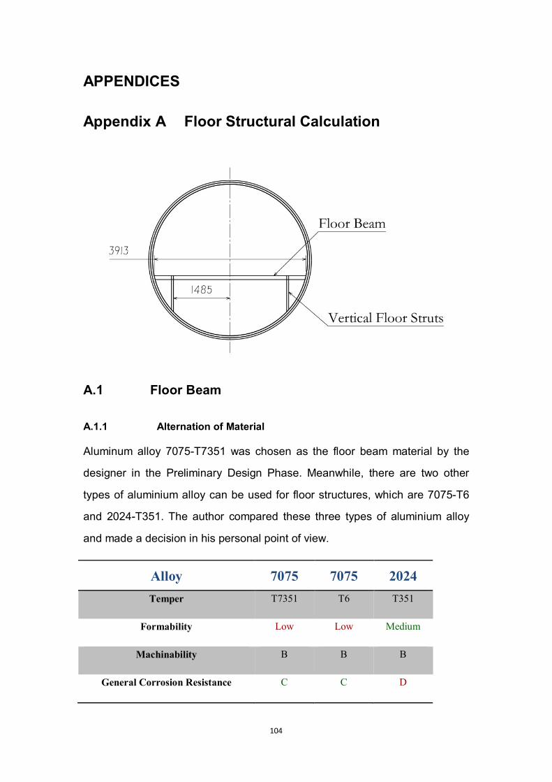
104
APPENDICES
Appendix A Floor Structural Calculation
A.1 Floor Beam
A.1.1 Alternation of Material
Aluminum alloy 7075-T7351 was chosen as the floor beam material by the
designer in the Preliminary Design Phase. Meanwhile, there are two other
types of aluminium alloy can be used for floor structures, which are 7075-T6
and 2024-T351. The author compared these three types of aluminium alloy
and made a decision in his personal point of view.
Alloy 7075 7075 2024 Temper T7351 T6 T351
Formability Low Low Medium
Machinability B B B
General Corrosion Resistance C C D
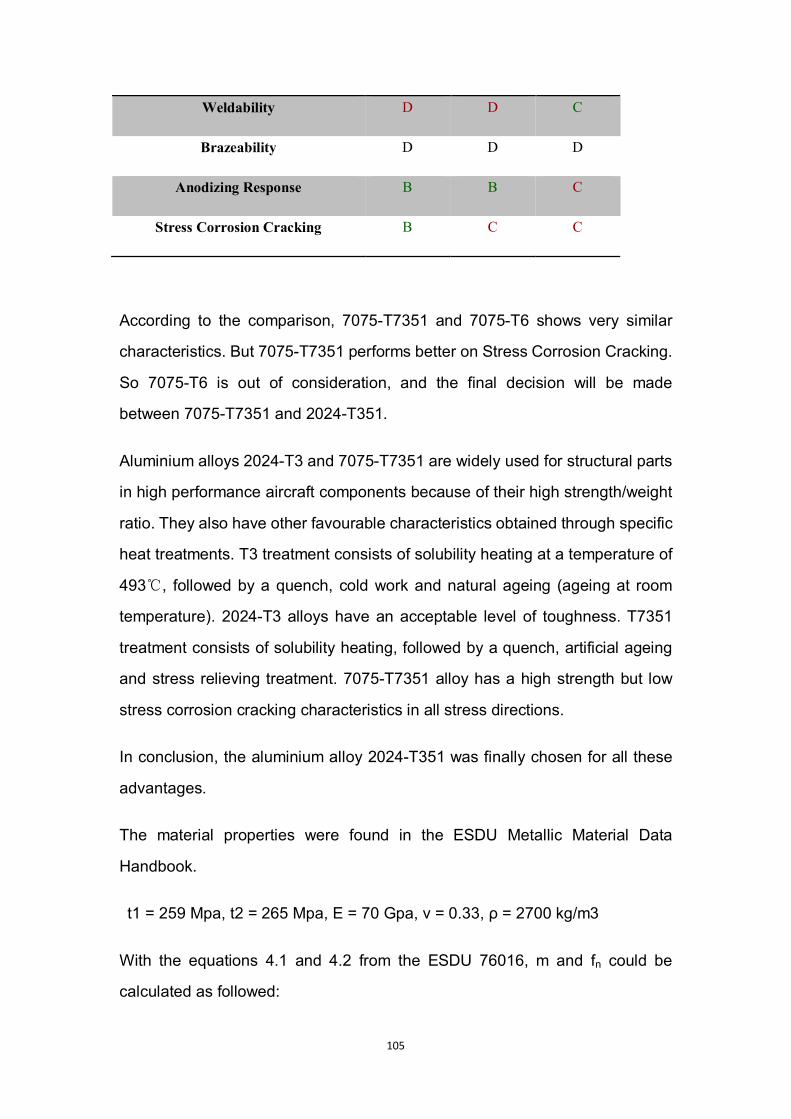
105
Weldability D D C
Brazeability D D D
Anodizing Response B B C
Stress Corrosion Cracking B C C
According to the comparison, 7075-T7351 and 7075-T6 shows very similar
characteristics. But 7075-T7351 performs better on Stress Corrosion Cracking.
So 7075-T6 is out of consideration, and the final decision will be made
between 7075-T7351 and 2024-T351.
Aluminium alloys 2024-T3 and 7075-T7351 are widely used for structural parts
in high performance aircraft components because of their high strength/weight
ratio. They also have other favourable characteristics obtained through specific
heat treatments. T3 treatment consists of solubility heating at a temperature of
493℃, followed by a quench, cold work and natural ageing (ageing at room
temperature). 2024-T3 alloys have an acceptable level of toughness. T7351
treatment consists of solubility heating, followed by a quench, artificial ageing
and stress relieving treatment. 7075-T7351 alloy has a high strength but low
stress corrosion cracking characteristics in all stress directions.
In conclusion, the aluminium alloy 2024-T351 was finally chosen for all these
advantages.
The material properties were found in the ESDU Metallic Material Data
Handbook.
t1 = 259 Mpa, t2 = 265 Mpa, E = 70 Gpa, ν = 0.33, ρ = 2700 kg/m3
With the equations 4.1 and 4.2 from the ESDU 76016, m and fn could be
calculated as followed:
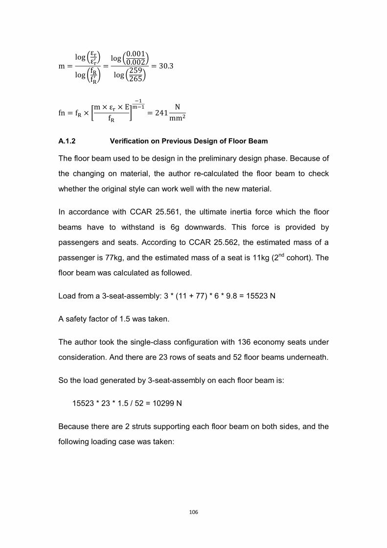
106
m =log ε
ε
log ff
=log 0.001
0.002log 259
265= 30.3
fn = f ×m× ε × E
f = 241N
mm
A.1.2 Verification on Previous Design of Floor Beam
The floor beam used to be design in the preliminary design phase. Because of
the changing on material, the author re-calculated the floor beam to check
whether the original style can work well with the new material.
In accordance with CCAR 25.561, the ultimate inertia force which the floor
beams have to withstand is 6g downwards. This force is provided by
passengers and seats. According to CCAR 25.562, the estimated mass of a
passenger is 77kg, and the estimated mass of a seat is 11kg (2nd cohort). The
floor beam was calculated as followed.
Load from a 3-seat-assembly: 3 * (11 + 77) * 6 * 9.8 = 15523 N
A safety factor of 1.5 was taken.
The author took the single-class configuration with 136 economy seats under
consideration. And there are 23 rows of seats and 52 floor beams underneath.
So the load generated by 3-seat-assembly on each floor beam is:
15523 * 23 * 1.5 / 52 = 10299 N
Because there are 2 struts supporting each floor beam on both sides, and the
following loading case was taken:
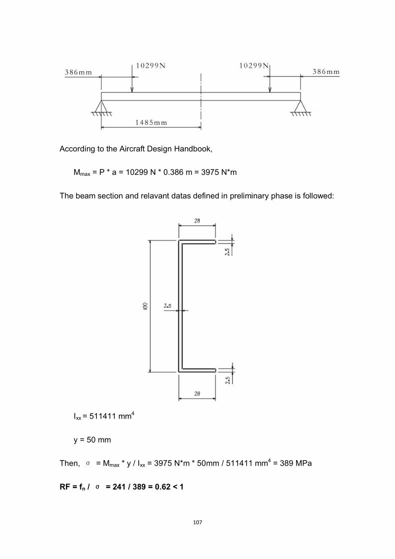
107
According to the Aircraft Design Handbook,
Mmax = P * a = 10299 N * 0.386 m = 3975 N*m
The beam section and relavant datas defined in preliminary phase is followed:
Ixx = 511411 mm4
y = 50 mm
Then, σ = Mmax * y / Ixx = 3975 N*m * 50mm / 511411 mm4 = 389 MPa
RF = fn / σ = 241 / 389 = 0.62 < 1

108
Therefore, the original floor beam designed in the preliminary phase is not
appropriate anymore due to the change of material. The author will explain his
modification on floor beam in the following chapter.
A.1.3 Modification on Floor Beam Design
(INA needs to be more than 864130)
The author modified the web thickness of the floor beam section from 2.5 mm
to 4.5 mm (shown in the following figure), then re-calculate the strength.
In accordance with the Aircraft Design Handbook
Ixx = [ ah3 – ( a – t1 )b3 ] / 12 = [ 28 * 1003 – ( 28 – 4.5 ) * 953 ] / 12
= 857590 mm4
Then, σ = Mmax * y / Ixx = 3975 N*m * 50mm / 857590 mm4 = 232 MPa
Thus, RF = fn / σ = 241 / 232 = 1.04 > 1
Maximum deflection:
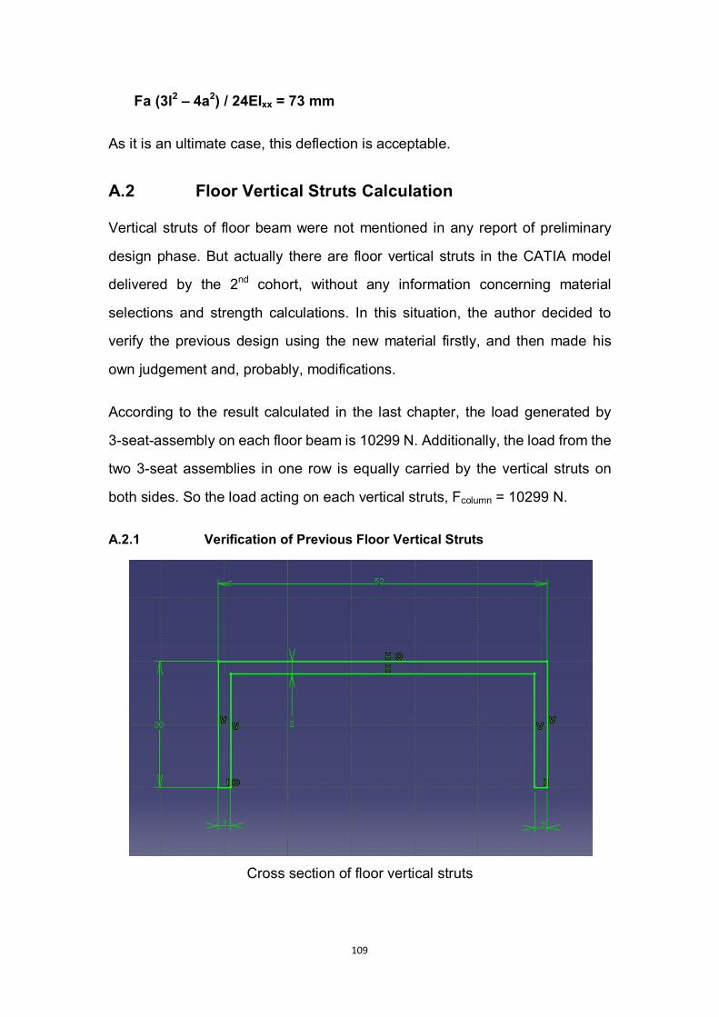
109
Fa (3l2 – 4a2) / 24EIxx = 73 mm
As it is an ultimate case, this deflection is acceptable.
A.2 Floor Vertical Struts Calculation
Vertical struts of floor beam were not mentioned in any report of preliminary
design phase. But actually there are floor vertical struts in the CATIA model
delivered by the 2nd cohort, without any information concerning material
selections and strength calculations. In this situation, the author decided to
verify the previous design using the new material firstly, and then made his
own judgement and, probably, modifications.
According to the result calculated in the last chapter, the load generated by
3-seat-assembly on each floor beam is 10299 N. Additionally, the load from the
two 3-seat assemblies in one row is equally carried by the vertical struts on
both sides. So the load acting on each vertical struts, Fcolumn = 10299 N.
A.2.1 Verification of Previous Floor Vertical Struts
Cross section of floor vertical struts

110
Floor vertical struts
σ = Fcritical / Acolumn = π2E/λ2
λ = l / i
i = (Imin / Acolumn)1/2
Because, Ix = [ ah3 – (a – t1) b3 ] / 12 = 68458.67 mm4
And, Iy = [ hx__
3 – b(x__
- t1 )3 + at2 (a - x__
)3 ] = 91486.33 mm4
Hence, Imin = Ix = 68458.67 mm4
Acolumn = 52 * 20 – 48 * 18 = 176 mm2
i = (68458.67 / 176)1/2 = 19.7
λ = 910 / 19.7 = 46.2
111
σcritical = 3.142 * 70 * 109 / 46.22 = 323 MPa
Meanwhile, σ = Fcolumn / A = 10299 / 176e-6 = 54 MPa
σ < σcritical
Thus, the previous floor vertical struts can be used.
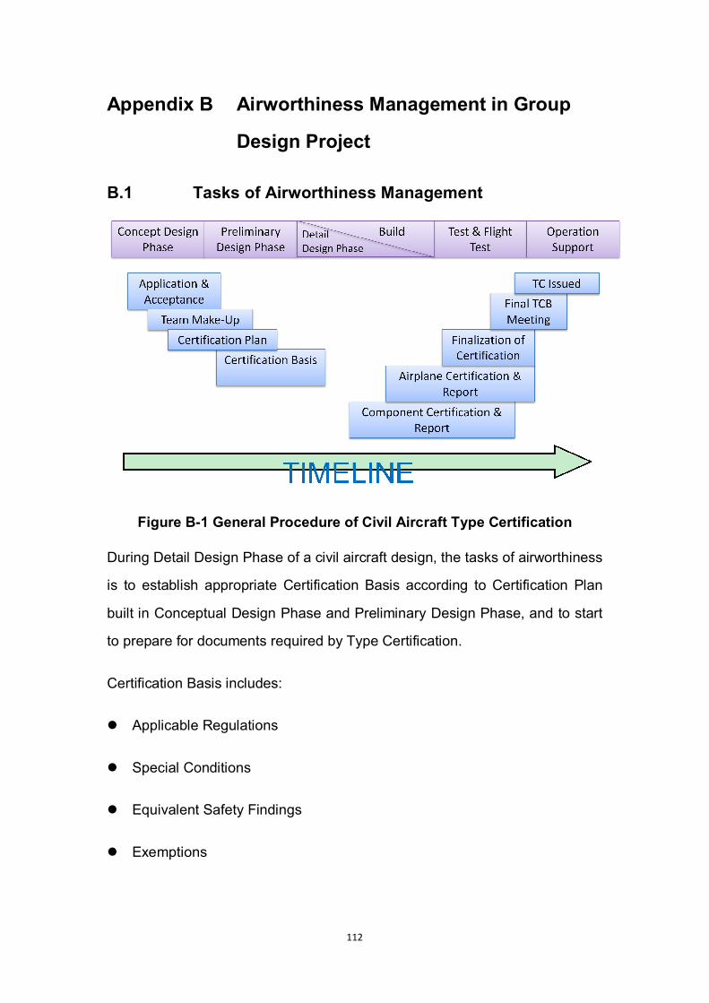
112
Appendix B Airworthiness Management in Group
Design Project
B.1 Tasks of Airworthiness Management
Figure B-1 General Procedure of Civil Aircraft Type Certification
During Detail Design Phase of a civil aircraft design, the tasks of airworthiness
is to establish appropriate Certification Basis according to Certification Plan
built in Conceptual Design Phase and Preliminary Design Phase, and to start
to prepare for documents required by Type Certification.
Certification Basis includes:
Applicable Regulations
Special Conditions
Equivalent Safety Findings
Exemptions
113
Being in charge of airworthiness management for structure design group within
Detailed Design Phase of Flying Crane Aircraft, the author’s work was focused
on the selection and adjustment of relevant airworthiness regulations, and
collaboration with specific designers to fully implement those regulations into
design philosophy and results. And the author’s work was based on the results
from preliminary design phase. The tasks of airworthiness within detailed
design phase include:
To help designers deeply understand the related items in the regulation
combined with their mission.
To assist designers to choose items into designing as well as adjust the
choice
To assist designers to optimize the means of compliance of chosen items
To ensure there are relevant materials to witness the means of appliance
to chosen item
To make sure the fulfilment of compliance to the regulation during the
whole course
To continuously improve the Airworthiness Compliance Matrix and check
the reasonability of the material to witness the means of appliance.
To make sure there is reasonable explanation to the suitability of every
item.
To make sure there is no contradiction in the applying of relevant items.
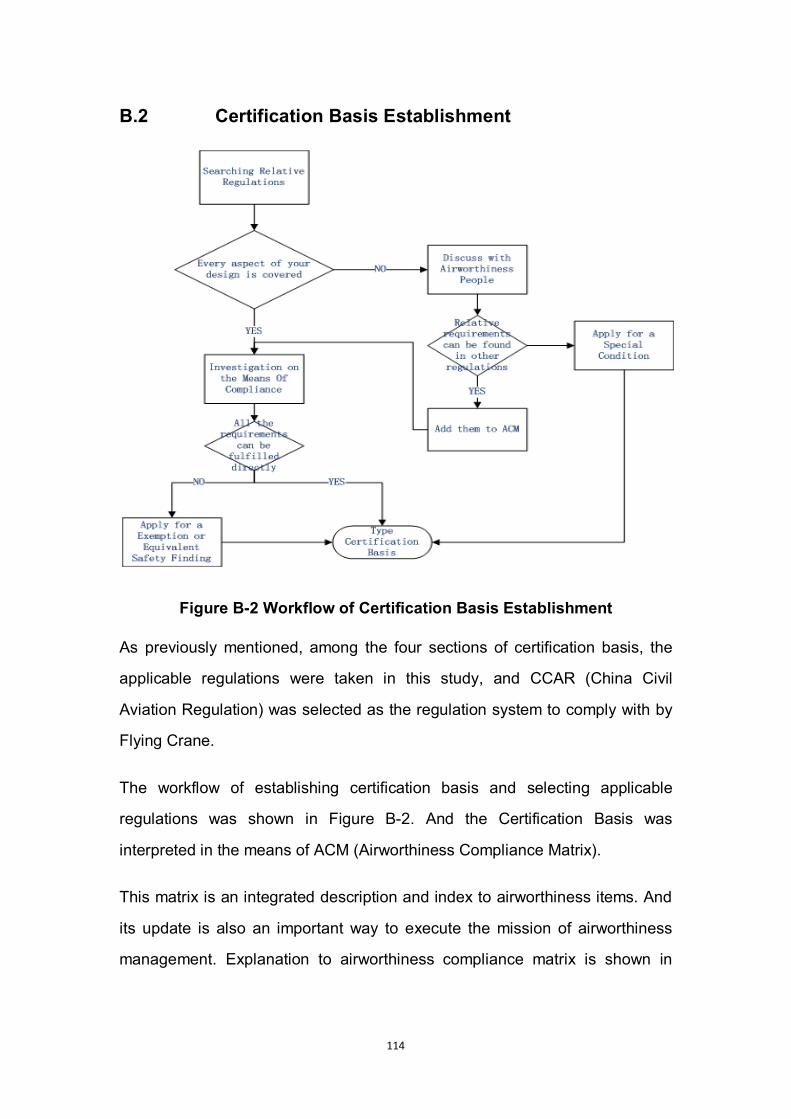
114
B.2 Certification Basis Establishment
Figure B-2 Workflow of Certification Basis Establishment
As previously mentioned, among the four sections of certification basis, the
applicable regulations were taken in this study, and CCAR (China Civil
Aviation Regulation) was selected as the regulation system to comply with by
Flying Crane.
The workflow of establishing certification basis and selecting applicable
regulations was shown in Figure B-2. And the Certification Basis was
interpreted in the means of ACM (Airworthiness Compliance Matrix).
This matrix is an integrated description and index to airworthiness items. And
its update is also an important way to execute the mission of airworthiness
management. Explanation to airworthiness compliance matrix is shown in
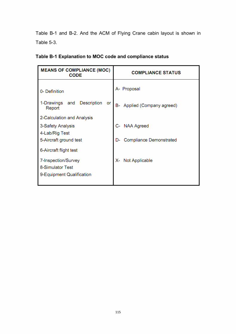
115
Table B-1 and B-2. And the ACM of Flying Crane cabin layout is shown in
Table 5-3.
Table B-1 Explanation to MOC code and compliance status
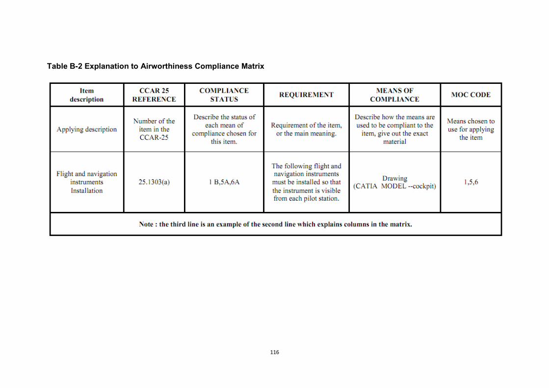
116
Table B-2 Explanation to Airworthiness Compliance Matrix
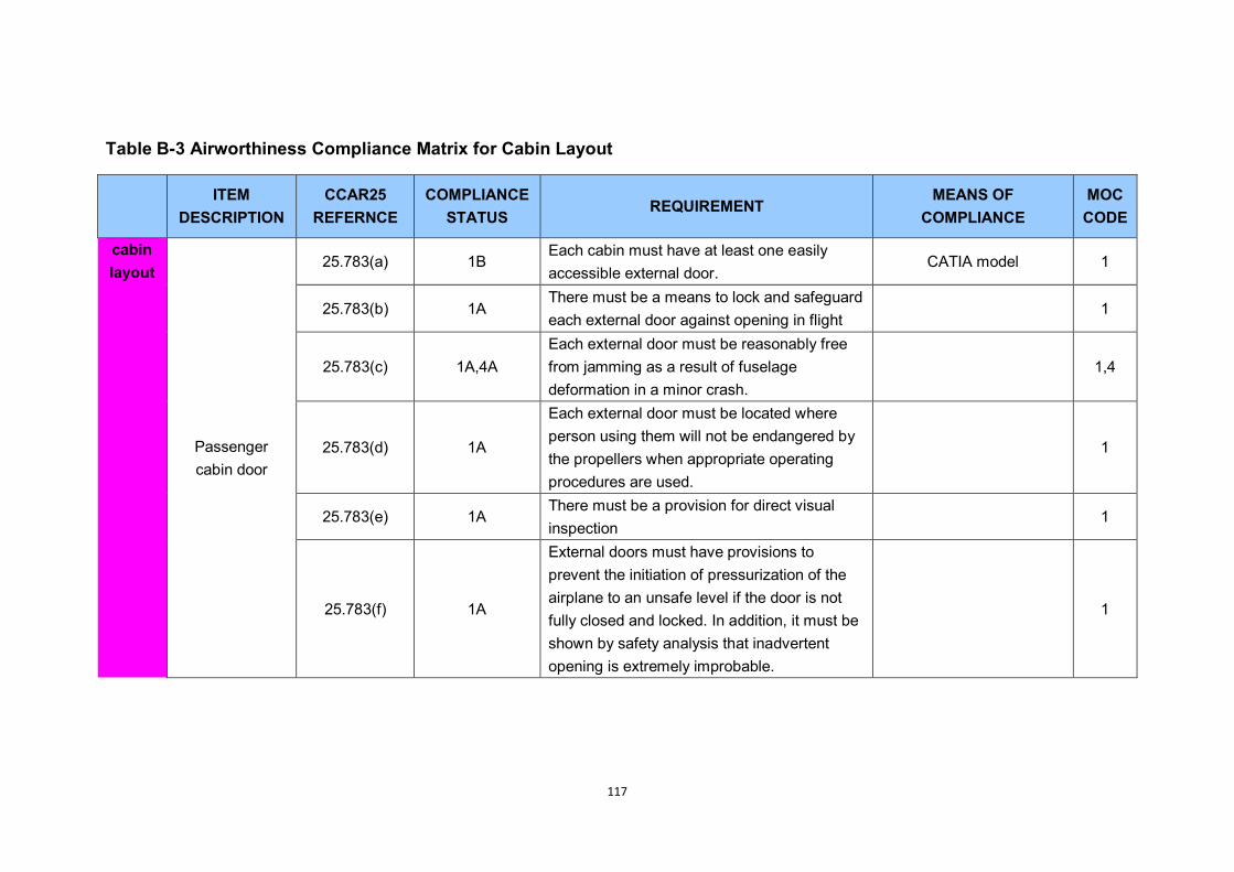
117
Table B-3 Airworthiness Compliance Matrix for Cabin Layout
ITEM
DESCRIPTION CCAR25
REFERNCE COMPLIANCE
STATUS REQUIREMENT
MEANS OF COMPLIANCE
MOC CODE
cabin layout
Passenger cabin door
25.783(a) 1B Each cabin must have at least one easily accessible external door.
CATIA model 1
25.783(b) 1A There must be a means to lock and safeguard each external door against opening in flight
1
25.783(c) 1A,4A Each external door must be reasonably free from jamming as a result of fuselage deformation in a minor crash.
1,4
25.783(d) 1A
Each external door must be located where person using them will not be endangered by the propellers when appropriate operating procedures are used.
1
25.783(e) 1A There must be a provision for direct visual inspection
1
25.783(f) 1A
External doors must have provisions to prevent the initiation of pressurization of the airplane to an unsafe level if the door is not fully closed and locked. In addition, it must be shown by safety analysis that inadvertent opening is extremely improbable.
1
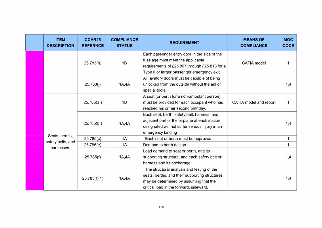
118
ITEM
DESCRIPTION CCAR25
REFERNCE COMPLIANCE
STATUS REQUIREMENT
MEANS OF COMPLIANCE
MOC CODE
25.783(h) 1B
Each passenger entry door in the side of the fuselage must meet the applicable requirements of §25.807 through §25.813 for a Type II or larger passenger emergency exit.
CATIA model 1
25.783(j) 1A,4A All lavatory doors must be capable of being unlocked from the outside without the aid of special tools.
1,4
Seats, berths, safety belts, and
harnesses.
25.785(a ) 1B A seat (or berth for a non-ambulant person) must be provided for each occupant who has reached his or her second birthday.
CATIA model and report 1
25.785(b ) 1A,4A
Each seat, berth, safety belt, harness, and adjacent part of the airplane at each station designated will not suffer serious injury in an emergency landing
1,4
25.785(c) 1A Each seat or berth must be approved. 1 25.785(e) 1A Demand to berth design 1
25.785(f) 1A,4A Load demand to seat or berth, and its supporting structure, and each safety belt or harness and its anchorage
1,4
25.785(f)(1) 1A,4A
The structural analysis and testing of the seats, berths, and their supporting structures may be determined by assuming that the critical load in the forward, sideward,
1,4

119
ITEM
DESCRIPTION CCAR25
REFERNCE COMPLIANCE
STATUS REQUIREMENT
MEANS OF COMPLIANCE
MOC CODE
downward, upward, and rearward directions.
25.785(f)(2) 1A,4A Each pilot seat must be designed for the reactions resulting from the application of the pilot forces prescribed in §25.395.
1,4
25.785(f)(3) 1A,4A
The inertia forces specified in §25.561 must be multiplied by a factor of 1.33 (instead of the fitting factor prescribed in §25.625) in determining the strength of the attachment of each seat to the structure and each belt or harness to the seat or structure.
1,4
25.785(h)(1) 1B Demand to flight attendant seats CATIA model 1
25.785(h)(3) 1B Positioned so that the seat will not interfere with the use of a passageway or exit when the seat is not in use.
CATIA model 1
25.785(h)(4) 1A Either forward or rearward facing with an energy absorbing rest that is designed to support the arms, shoulders, head, and spine.
1
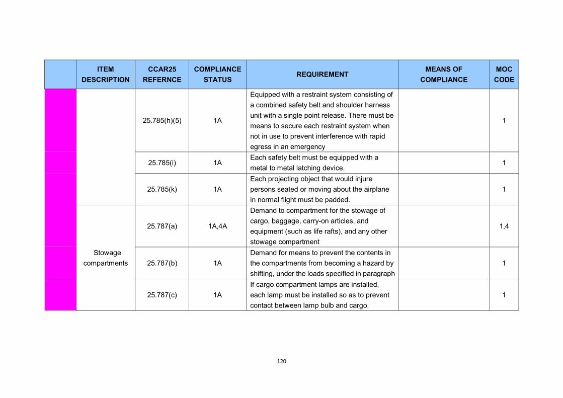
120
ITEM
DESCRIPTION CCAR25
REFERNCE COMPLIANCE
STATUS REQUIREMENT
MEANS OF COMPLIANCE
MOC CODE
25.785(h)(5) 1A
Equipped with a restraint system consisting of a combined safety belt and shoulder harness unit with a single point release. There must be means to secure each restraint system when not in use to prevent interference with rapid egress in an emergency
1
25.785(i) 1A Each safety belt must be equipped with a metal to metal latching device.
1
25.785(k) 1A Each projecting object that would injure persons seated or moving about the airplane in normal flight must be padded.
1
Stowage compartments
25.787(a) 1A,4A
Demand to compartment for the stowage of cargo, baggage, carry-on articles, and equipment (such as life rafts), and any other stowage compartment
1,4
25.787(b) 1A Demand for means to prevent the contents in the compartments from becoming a hazard by shifting, under the loads specified in paragraph
1
25.787(c) 1A If cargo compartment lamps are installed, each lamp must be installed so as to prevent contact between lamp bulb and cargo.
1
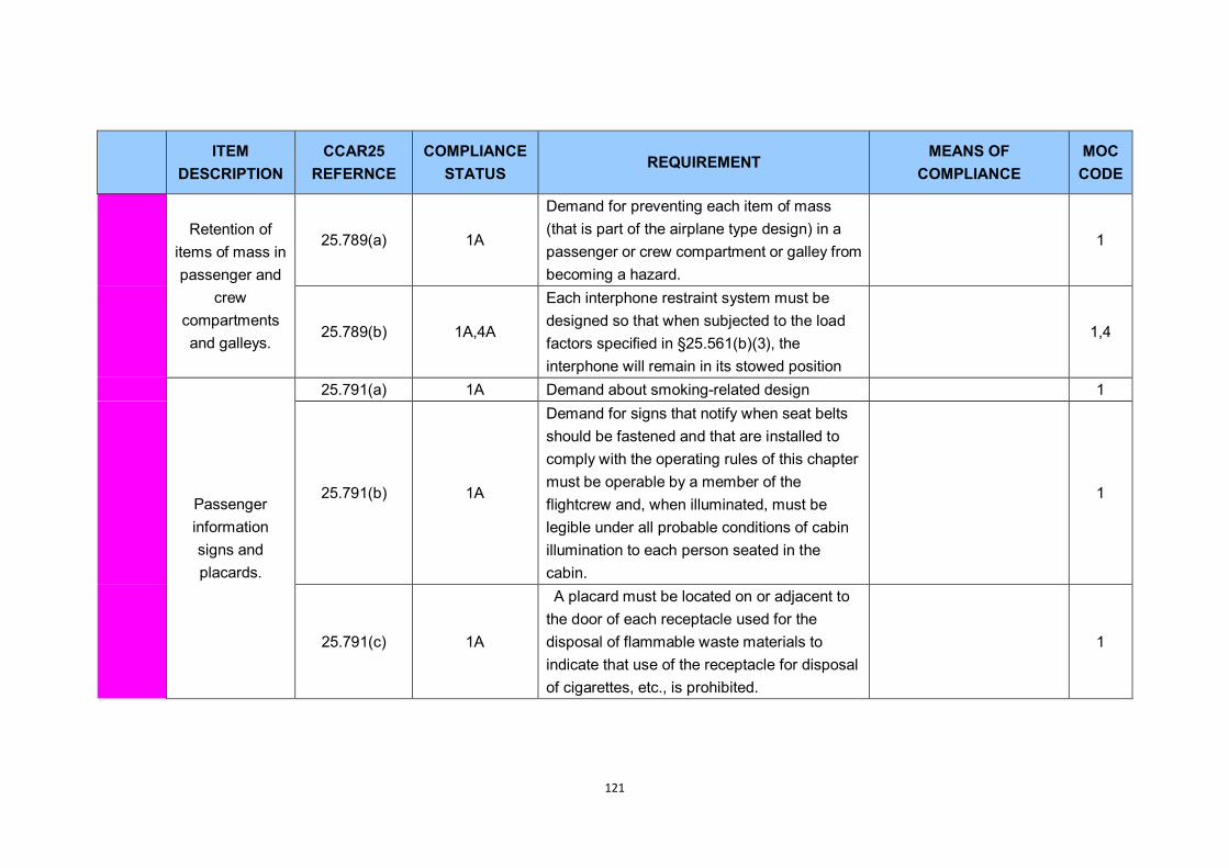
121
ITEM
DESCRIPTION CCAR25
REFERNCE COMPLIANCE
STATUS REQUIREMENT
MEANS OF COMPLIANCE
MOC CODE
Retention of items of mass in passenger and
crew compartments and galleys.
25.789(a) 1A
Demand for preventing each item of mass (that is part of the airplane type design) in a passenger or crew compartment or galley from becoming a hazard.
1
25.789(b) 1A,4A
Each interphone restraint system must be designed so that when subjected to the load factors specified in §25.561(b)(3), the interphone will remain in its stowed position
1,4
Passenger information signs and placards.
25.791(a) 1A Demand about smoking-related design 1
25.791(b) 1A
Demand for signs that notify when seat belts should be fastened and that are installed to comply with the operating rules of this chapter must be operable by a member of the flightcrew and, when illuminated, must be legible under all probable conditions of cabin illumination to each person seated in the cabin.
1
25.791(c) 1A
A placard must be located on or adjacent to the door of each receptacle used for the disposal of flammable waste materials to indicate that use of the receptacle for disposal of cigarettes, etc., is prohibited.
1
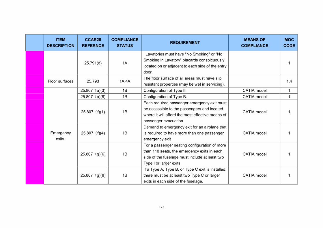
122
ITEM
DESCRIPTION CCAR25
REFERNCE COMPLIANCE
STATUS REQUIREMENT
MEANS OF COMPLIANCE
MOC CODE
25.791(d) 1A
Lavatories must have "No Smoking" or "No Smoking in Lavatory" placards conspicuously located on or adjacent to each side of the entry door.
1
Floor surfaces 25.793 1A,4A The floor surface of all areas must have slip resistant properties (may be wet in servicing).
1,4
Emergency exits.
25.807(a)(3) 1B Configuration of Type III. CATIA model 1 25.807(a)(8) 1B Configuration of Type B. CATIA model 1
25.807(f)(1) 1B
Each required passenger emergency exit must be accessible to the passengers and located where it will afford the most effective means of passenger evacuation.
CATIA model 1
25.807(f)(4) 1B Demand to emergency exit for an airplane that is required to have more than one passenger emergency exit
CATIA model 1
25.807(g)(6) 1B
For a passenger seating configuration of more than 110 seats, the emergency exits in each side of the fuselage must include at least two Type I or larger exits
CATIA model 1
25.807(g)(8) 1B If a Type A, Type B, or Type C exit is installed, there must be at least two Type C or larger exits in each side of the fuselage.
CATIA model 1
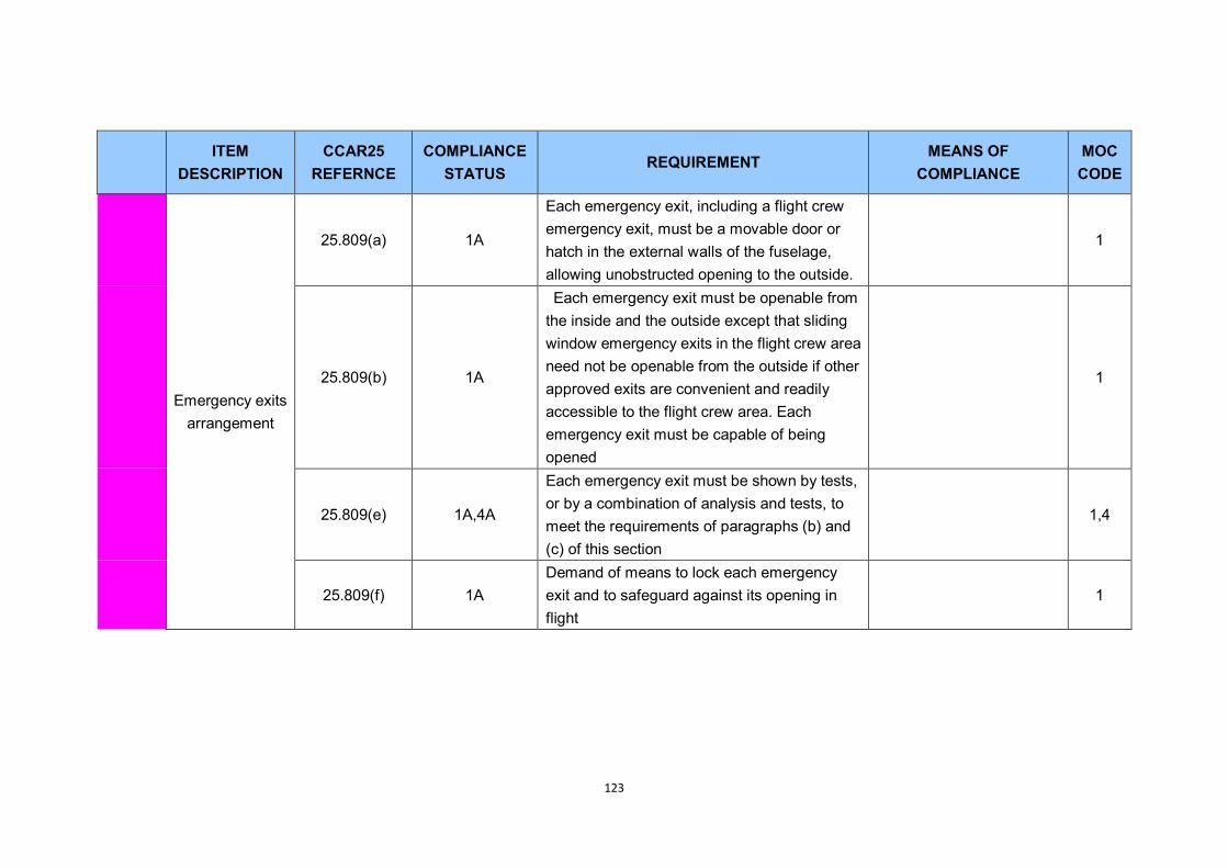
123
ITEM
DESCRIPTION CCAR25
REFERNCE COMPLIANCE
STATUS REQUIREMENT
MEANS OF COMPLIANCE
MOC CODE
Emergency exits arrangement
25.809(a) 1A
Each emergency exit, including a flight crew emergency exit, must be a movable door or hatch in the external walls of the fuselage, allowing unobstructed opening to the outside.
1
25.809(b) 1A
Each emergency exit must be openable from the inside and the outside except that sliding window emergency exits in the flight crew area need not be openable from the outside if other approved exits are convenient and readily accessible to the flight crew area. Each emergency exit must be capable of being opened
1
25.809(e) 1A,4A
Each emergency exit must be shown by tests, or by a combination of analysis and tests, to meet the requirements of paragraphs (b) and (c) of this section
1,4
25.809(f) 1A Demand of means to lock each emergency exit and to safeguard against its opening in flight
1
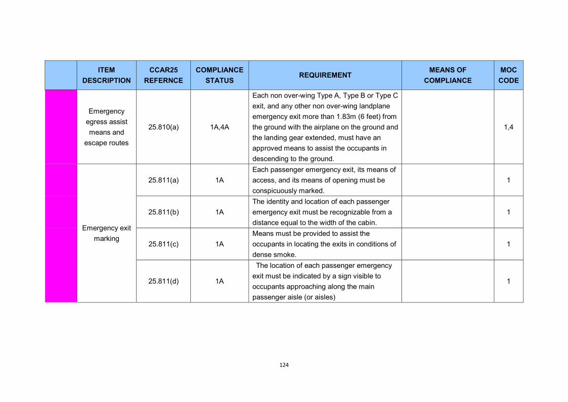
124
ITEM
DESCRIPTION CCAR25
REFERNCE COMPLIANCE
STATUS REQUIREMENT
MEANS OF COMPLIANCE
MOC CODE
Emergency egress assist means and
escape routes
25.810(a) 1A,4A
Each non over-wing Type A, Type B or Type C exit, and any other non over-wing landplane emergency exit more than 1.83m (6 feet) from the ground with the airplane on the ground and the landing gear extended, must have an approved means to assist the occupants in descending to the ground.
1,4
Emergency exit marking
25.811(a) 1A Each passenger emergency exit, its means of access, and its means of opening must be conspicuously marked.
1
25.811(b) 1A The identity and location of each passenger emergency exit must be recognizable from a distance equal to the width of the cabin.
1
25.811(c) 1A Means must be provided to assist the occupants in locating the exits in conditions of dense smoke.
1
25.811(d) 1A
The location of each passenger emergency exit must be indicated by a sign visible to occupants approaching along the main passenger aisle (or aisles)
1
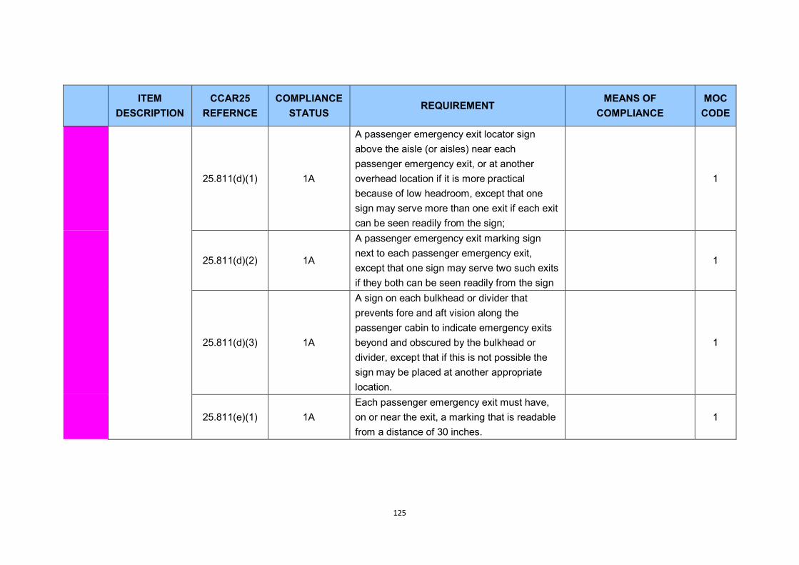
125
ITEM
DESCRIPTION CCAR25
REFERNCE COMPLIANCE
STATUS REQUIREMENT
MEANS OF COMPLIANCE
MOC CODE
25.811(d)(1) 1A
A passenger emergency exit locator sign above the aisle (or aisles) near each passenger emergency exit, or at another overhead location if it is more practical because of low headroom, except that one sign may serve more than one exit if each exit can be seen readily from the sign;
1
25.811(d)(2) 1A
A passenger emergency exit marking sign next to each passenger emergency exit, except that one sign may serve two such exits if they both can be seen readily from the sign
1
25.811(d)(3) 1A
A sign on each bulkhead or divider that prevents fore and aft vision along the passenger cabin to indicate emergency exits beyond and obscured by the bulkhead or divider, except that if this is not possible the sign may be placed at another appropriate location.
1
25.811(e)(1) 1A Each passenger emergency exit must have, on or near the exit, a marking that is readable from a distance of 30 inches.
1

126
ITEM
DESCRIPTION CCAR25
REFERNCE COMPLIANCE
STATUS REQUIREMENT
MEANS OF COMPLIANCE
MOC CODE
25.811(e)(2) 1A
Each Type A, Type B, Type C or Type I passenger emergency exit operating handle must-- (ⅰ)Be self-illuminated with an initial brightness of at least 160 micro-lamberts; or (ii) Be conspicuously located and well illuminated by the emergency lighting even in conditions of occupant crowding at the exit.
1
25.811(f) 1A
Each emergency exit that is required to be openable from the outside, and its means of opening, must be marked on the outside of the airplane. In addition, the following apply
1
25.811(f)(1) 1A
The outside marking for each passenger emergency exit in the side of the fuselage must include a 50mm (2-inch) colored band outlining the exit.
1
25.811(f)(2) 1A Demand to outside marking including the band 1
Emergency lighting
25.812(a) 1A,4A
An emergency lighting system, independent of the main lighting system, must be installed. However, the sources of general cabin illumination may be common to both the emergency and the main lighting systems if the power supply to the emergency lighting
1,4
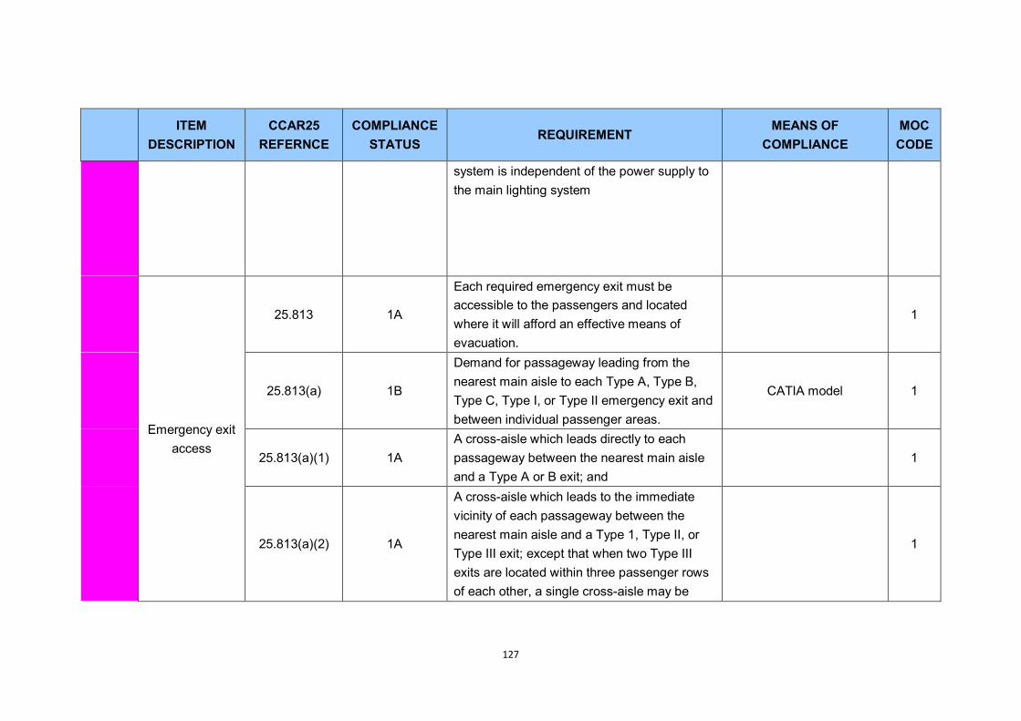
127
ITEM
DESCRIPTION CCAR25
REFERNCE COMPLIANCE
STATUS REQUIREMENT
MEANS OF COMPLIANCE
MOC CODE
system is independent of the power supply to the main lighting system
Emergency exit access
25.813 1A
Each required emergency exit must be accessible to the passengers and located where it will afford an effective means of evacuation.
1
25.813(a) 1B
Demand for passageway leading from the nearest main aisle to each Type A, Type B, Type C, Type I, or Type II emergency exit and between individual passenger areas.
CATIA model 1
25.813(a)(1) 1A A cross-aisle which leads directly to each passageway between the nearest main aisle and a Type A or B exit; and
1
25.813(a)(2) 1A
A cross-aisle which leads to the immediate vicinity of each passageway between the nearest main aisle and a Type 1, Type II, or Type III exit; except that when two Type III exits are located within three passenger rows of each other, a single cross-aisle may be
1

128
ITEM
DESCRIPTION CCAR25
REFERNCE COMPLIANCE
STATUS REQUIREMENT
MEANS OF COMPLIANCE
MOC CODE
used if it leads to the vicinity between the passageways from the nearest main aisle to each exit
25.813(b) 1A Adequate space to allow crewmember(s) to assist in the evacuation of passengers must be provided as follows
1
25.813(b)(1) 1A The assist space must not reduce the unobstructed width of the passageway below that required for the exit
1
25.813(b)(2) 1B
For each Type A or Type B exit, assist space must be provided at each side of the exit regardless of whether a means is required by §25.810(a) to assist passengers in descending to the ground from that exit.
CATIA model 1
25.813(e) 1B No door may be installed in any partition between passenger compartments
CATIA model 1
Width of aisle 25.815 1B The passenger aisle width at any point between seats must equal or exceed the values sepicified
CATIA model 1

129
ITEM
DESCRIPTION CCAR25
REFERNCE COMPLIANCE
STATUS REQUIREMENT
MEANS OF COMPLIANCE
MOC CODE
Maximum number of seats
abreast 25.817 1B
On airplanes having only one passenger aisle, no more than three seats abreast may be placed on each side of the aisle in any one row.
CATIA model 1
Pressurized cabins
25.841 1A,4A
Pressurized cabins and compartments to be occupied must be equipped to provide a cabin pressure altitude of not more than 2400m (8,000 feet) at the maximum operating altitude of the airplane under normal operating conditions.
1 4
Tests for pressurized
cabins. 25.843 4A
Strength testand functional tests of pressure cabin must be done.
4
safety equipment
25.1411(a) 1A Accessibility. Required safety equipment to be used by the crew in an emergency must be readily accessible.
1
25.1411(b) 1A Demand to Stowage provisions. 1
25.1411(c) 1A
(c) Emergency exit descent device. The stowage provisions for the emergency exit descent device required by §25.809(f) must be at the exits for which they are intended.
1

130
ITEM
DESCRIPTION CCAR25
REFERNCE COMPLIANCE
STATUS REQUIREMENT
MEANS OF COMPLIANCE
MOC CODE
25.1411(d)(1) 1B
(1) The stowage provisions for the liferafts described in §25.1415 must accommodate enough rafts for the maximum number of occupants for which certification for ditching is requested.
1
25.1411(d)(2) 1B (2) Liferafts must be stowed near exits through which the rafts can be launched during an unplanned ditching.
1
25.1411(d)(3) 1A
(3) Rafts automatically or remotely released outside the airplane must be attached to the airplane by means of the static line prescribed in §25.1415.
1
25.1411(d)(4) 1A
The stowage provisions for each portable liferaft must allow rapid detachment and removal of the raft for use at other than the intended exits.
1
25.851 1A Fire Extinguishers CATIA Model and Report 1
Floor
25,793 1A Floor Surface CATIA Model and Report 1
25.561(3)(iv) 1A
The occupant experiences the following ultimate inertia forces acting separately relative to the surrounding structure: downward, 6.0g
CATIA Model and Report 1