Embed Size (px)
Citation preview

CR 1100, CR 1200, CR 1400
QUICK START TROUBLESHOOTING MANUAL
2/09 Revised 6/12FORM NO. 56043130
Obsolete Nilfisk MODELS 56304009, 56304010, 56304011, 56304012, 56304013, 56304014, 56304015, 56304016, 56304017
Active Nilfisk MODELS 56306059, 56306060, 56306061, 56306062, 56306063, 56306064, 56307236(HT), 56307238(HT), 56307237(HT), 56307239(HT)
All model numbers starting with “56306” and “56307” are manufactured with the 2007 certified engine.

106 - FORM NO. 56043130 / CR 1100, 1200, 1400
TABLE OF CONTENTSGENERAL INFORMATION ................................................................................................................................................1-2SAFETY INSTRUCTIONS .................................................................................................................................................... 3SPECIFICATIONS .............................................................................................................................................................4-5MAINTENANCE .................................................................................................................................................................6-8PM CHECKLIST ..............................................................................................................................................................9-10KNOW YOUR MACHINE ...............................................................................................................................................12-25 CONTROL ERROR CODES ........................................................................................................................................15-17 GENERAL MACHINE TROUBLESHOOTING GUIDE TABLE OF CONTENTS ............................................................... 18 OPERATOR’S COMPARTMENT ...................................................................................................................................... 19 GENERAL TROUBLESHOOTING FLOW CHARTS ....................................................................................................20-25WHEEL DRIVE SYSTEM .................................................................................................................................................... 26 TROUBLESHOOTING CHECK LIST ................................................................................................................................ 26STEERING SYSTEM .......................................................................................................................................................... 27 STEERING SYSTEM TROUBLESHOOTING OVERVIEW .............................................................................................. 27 TROUBLESHOOTING GUIDE.......................................................................................................................................... 27SWEEPING SYSTEM ....................................................................................................................................................28-35 MAIN BROOM .............................................................................................................................................................28-29 SIDE BROOMS ............................................................................................................................................................30-31 SIDE BROOM LIFT ACTUATOR ...................................................................................................................................... 32 DUST CONTROL IMPELLER ......................................................................................................................................33-34 SHAKER MOTOR ............................................................................................................................................................. 35HOPPER SYSTEM ........................................................................................................................................................36-42 LIFT CYLINDER ..........................................................................................................................................................36-39 DUMP DOOR CYLINDER............................................................................................................................................40-42SCRUB SYSTEM ...........................................................................................................................................................43-52 DECK LIFT ACTUATOR ..............................................................................................................................................43-50 SCRUB MOTORS ........................................................................................................................................................51-52SOLUTION SYSTEM .......................................................................................................................................................... 53 SOLUTION SOLENOID VALVE ........................................................................................................................................ 53RECOVERY SYSTEM ...................................................................................................................................................54-58 VACUUM MOTOR .......................................................................................................................................................54-56 SQUEEGEE LIFT ACTUATOR ....................................................................................................................................57-58ENGINE SYSTEM .........................................................................................................................................................59-62 ENGINE SPECIFICATIONS.............................................................................................................................................. 59 ENGINE MAINTENANCE ................................................................................................................................................. 59 CHECK ENGINE LIGHT TROUBLESHOOTING NON-CERTIFIED & TIER I .................................................................. 60 1.6L DTC CODES FOR TIER I ......................................................................................................................................... 61 MISCELLANEOUS ENGINE SYSTEM INFORMATION ................................................................................................... 62 1.6L DTC CODES FOR TIER II ........................................................................................................................................ 63 MISCELLANEOUS ENGINE SYSTEM INFORMATION ................................................................................................... 64 ENGINE FUEL SYSTEM FOR GASOLINE MODELS .................................................................................................64-66HYDRAULIC SYSTEM ..................................................................................................................................................67-74 HYDRAULIC SYSTEM TROUBLESHOOTING ................................................................................................................ 67 GENERAL HYDRAULIC SPECIFICATIONS TABLE ........................................................................................................ 68 SETTING RELIEF VALVES .........................................................................................................................................69-71 HYDRAULIC DIAGRAM ................................................................................................................................................... 72 HYDRAULIC SCHEMATIC ............................................................................................................................................... 73 HYDRAULIC COMPONENT LOCATION .......................................................................................................................... 74ELECTRICAL SYSTEM .................................................................................................................................................75-73 ELECTRICAL COMPONENT LOCATION......................................................................................................................... 75 WIRING DIAGRAM FOR TIER I ....................................................................................................................................... 76 WIRING SCHEMATIC FOR TIER I ................................................................................................................................... 77 WIRING DIAGRAM FOR TIER II ...................................................................................................................................... 78 WIRING SCHEMATIC FOR TIER II .................................................................................................................................. 79 WIRING DIAGRAM FOR DIESEL ..................................................................................................................................... 80 ENGINE HARNESS GASOLINE/PETROL LPG TIER I .................................................................................................... 81 ENGINE HARNESS ECM DETAIL FOR TIER I ................................................................................................................ 82 ENGINE HARNESS GASOLINE/PETROL TIER II ........................................................................................................... 83 ENGINE HARNESS LPG TIER II...................................................................................................................................... 84 ENGINE WIRING HARNESS DETAIL FOR TIER II.......................................................................................................... 85PROGRAMMABLE CONTROL OPTIONS .....................................................................................................................87-95INPUT/OUTPUT TABLES ..............................................................................................................................................96-98AXP/EDS SYSTEM ......................................................................................................................................................99-104
Note: All references to right, left, front, or rear in this manual are as seen from the operator’s stand-point.

FORM NO. 56043130 / CR 1100, 1200, 1400 - 1
INTRODUCTIONThis manual will help you get the most from your Nilfisk rider Scrubber-Sweeper. Read it thoroughly before servicing the machine.Note: Bold numbers and letters in parentheses and underlined indicate an item illustrated on pages 9-10 i.e. (B).This product is intended for commercial use only.
PARTS AND SERVICERepairs, when required, should be performed by your Authorized Nilfisk Service Center, who employs factory trained service personnel, and maintains an inventory of Nilfisk original replacement parts and accessories.
Call the NILFISK DEALER named below for repair parts or service. Please specify the Model and Serial Number when discussing your machine.
(Dealer, affix service sticker here.)
NAME PLATEThe Model Number and Serial Number of your machine are shown on the Nameplate on the machine. This information is needed when ordering repair parts for the machine. Use the space below to note the Model Number and Serial Number of your machine for future reference.
MODEL NUMBER
SERIAL NUMBER
HOPPER SAFETY SUPPORT
WARNING!Make sure the Hopper Safety Support (KK) is in place whenever attempting to do any maintenance work under or near the raised hopper. The Hopper Safety Support (KK) holds the hopper in the raised position to allow work to be performed under the hopper. NEVER rely on the machine’s hydraulic components to safely support the hopper.
JACKING THE MACHINE
CAUTION!Never work under a machine without safety stands or blocks to support the machine.• When jacking the machine, do so at designated locations (Do Not jack on the hopper) – see jacking locations (44).
GENERAL INFORMATION

2 - FORM NO. 56043130 / CR 1100, 1200, 1400
TRANSPORTING THE MACHINE
CAUTION!Before transporting the machine on an open truck or trailer, make sure that . . .• All access doors are latched securely.• The machine is tied down securely - see tie-down locations (6).• The machine parking brake is set.
TOWING OR PUSHING A DISABLED MACHINE
CAUTION!
OTHER MANUALS AVAILABLEThe following manuals are available for your Rider Scrubber/Sweeper:• Parts List - Form Numbers 56042518 (main parts list) 56042519 (Hydraulic Systems) 56042508 (Options/Accessories) 56042520 (Engine Systems 2007 certified)• Operation Manual - Form Numbers 56041546 (Danish, Norwegian, Swedish, Finnish) 56041547 (German, French, Dutch, Russian) 56041548 (Spanish, Portuguese, Italian, Greek) 56041578 (Estonian, Latvian, Lithuanian, Slovenian) 56041579 (Slovakian, Czech, Polish, Hungarian) 56041669 (English, Turkish)• Mechanical Repair Service Manual 56043131• EngineManuals(TierI) 1.6L Industrial Engine Operator Manual (excerpt from 16LECSS) 56041564 1.6L Industrial Engine Service Manual 36100009* 1.6L Emission Certified Industrial Engine Emission Control System Service Manual 16LECSS*• EngineManuals(TierII) 1.6L Industrial Engine Operator Manual (excerpt from 16LECSS) 56041564 1.6L Industrial Engine Service Manual 36100009* PSI Tier 2 1.6L PFI Certified Engine Service Manual G/LP PSI1P6LPFI-A* V1505 Kubota Diesel Engine Service Manual (WSM English) 97897-02432 V1505 Kubota Diesel Engine Service Manual (WSM English, French, German) 97897-01640 V1505 Kubota Diesel Engine Operator Manual (English, French, German, Italian, Spanish) 16622-8916-3
*Available in electronic format only
BOTTOM VIEW OF HYDROSTATIC PUMP
GENERAL INFORMATION
The machine’s drive propelling pump is manufactured with a selectable tow valve. This valve prevents damage to the hydraulic system when the machine is being towed/pushed short distances without use of the engine.To access the valve, open the Engine Compartment Door (22) and lift off the Right Engine Compartment Access Panel (37). Locate the valve as shown on the underside of the hydrostatic pump by reaching under the radiator. Turn the valve 90 degrees, this disengages the hydrostatic lock between the motor and pump.The hydrostatic pump can be damaged if the machine is towed with the valve in the normal working position (A). Reference the illustration below for the normal working setting (A) and the free wheeling towing setting (B). Note: If the tow valve is left in free wheeling (B) position the hydrostatic pump can’t drive the machine FWD or REV. No damage will result, just re-set valve to the normal working setting (A). Tow or push machine no faster than a normal walking pace (2-3 miles per hour) and for short distances only. If the machine is to be moved long distances the drive wheel needs to be raised off the floor and placed on a suitable transport dolly.

FORM NO. 56043130 / CR 1100, 1200, 1400 - 3
CAUTIONS AND WARNINGSSYMBOLSNilfisk uses the symbols below to signal potentially dangerous conditions. Always read this information carefully and take the necessary steps to protect personnel and property.
DANGER!Is used to warn of immediate hazards that will cause severe personal injury or death.
WARNING!Is used to call attention to a situation that could cause severe personal injury.
CAUTION!Is used to call attention to a situation that could cause minor personal injury or damage to the machine or other property.
GENERAL SAFETY INSTRUCTIONSSpecific Cautions and Warnings are included to warn you of potential danger of machine damage or bodily harm.
DANGER!• This machine emits exhaust gases (carbon monoxide) that can cause serious injury or death, always provide adequate
ventilation when operating this machine.
WARNING!• This machine shall be used only by properly trained and authorized persons.• While on ramps or inclines, avoid sudden stops when loaded. Avoid abrupt sharp turns. Use low speed down hills.• Keep sparks, flame and smoking materials away from the battery and fuel system.• Remove all jewelry when working near electrical components.• Take precautions to prevent hair, jewelry, or loose clothing from becoming caught in moving parts.• Turn the key switch off (O), disconnect the battery, and set the parking brake before servicing the machine.• Never work under a machine without safety blocks or stands to support the machine.• Do not dispense flammable cleaning agents, operate the machine on or near these agents, or operate in areas where
flammable liquids exist.• Do not clean this machine with a pressure washer.• Keep the LP tank Service Valve closed when the tank is not in use.
CAUTION!• This machine is not approved for use on public paths or roads.• This machine is not suitable for picking up hazardous dust.• When operating this machine, ensure that third parties, particularly children, are not endangered.• Before performing any service function carefully read all instructions pertaining to that function.• Do not leave the machine unattended without first turning the key switch off (O), removing the key and applying the parking
brake.• Turn the key switch off (O) before changing the brooms and brushes, and before opening any access panels.• Use caution when moving this machine in below freezing temperature conditions. Any water in the solution or recovery tanks
or in the hose lines could freeze, causing damage to valves and fittings. Flush with windshield washer fluid.• The battery must be removed from the machine before the machine is scrapped. The disposal of the battery should be safely
done in accordance with your local environmental regulations.
SAVE THESE INSTRUCTIONS

4 - FORM NO. 56043130 / CR 1100, 1200, 1400
SPECIFICATIONSGeneralSpecificationscommontoAll Models English (Metric)Dimensions Gas & Propane
Length 105 inches (267cm)Height 58 inches (147cm)Height w/overhead guard 79 inches (200cm)Ground clearance 3 inches (7.6cm)Minimum ceiling height dumping clearance 92 inches (233.6cm)
WeightsNet weight* 4040 lbs. (1832kg)Gross weight** 4720 lbs. (2141kg)
Speed and GradeabilityMaximum travel speed 6 mph (9.6km/h)Maximum reverse speed 4 mph (6.4km/h)Maximum grade angle scrubbing 6 deg.Maximum grade angle non-scrubbing 8 deg.
Sound LevelAt operators ear 85.1 dBA
Sweep SystemSweeping path w/out side broom(s) 40 inches (102cm)Main broom length 40 inches (102cm)Main broom diameter 14 inches (35.5cm)Side broom diameter 20 inches (50.8cm)Side broom bristle length 7 inches (17.7cm)
Hopper SystemCapacity 9.2 Cu. Ft. (261 L)Lifting capacity 550 lbs. (250kg)Dump height (variable) Max. 60 inches (152cm)Dump height with door open 56-1/2 inches (143.5cm)
Dust Control SystemFilter type: Pleated paper panelFilter dimension 3-3/16” x 20” x 27” (8cm x 50.8cm x 68.5cm)Filter media area 78 ft2 (7.25m2)
Steering SystemType: Power steering unit with rack and pinionTurns lock to lock right: 4-3/8Turns lock to lock left: 3-3/8Minimum aisle turn width 118 in. (300cm) left and right
Hydraulic SystemOil type: SAE 10W-30System fill capacity 11 gal. (41.6 L)
Engine SystemEngine coolant fill capacity 10-11 qts. (9.5-10.4L)
Recovery SystemVacuum water lift (sealed) minimum 22 inchesVacuum water lift (open hole adapter 1”) minimum 20 inches
*Net Weight: Standard machine without options, empty solution and recovery tanks, without removable scrub brushes and full tank of fuel.**Gross Weight: Standard machine without options, full solution tank and empty recovery tank, with removable scrub brushes and full tank of fuel.

FORM NO. 56043130 / CR 1100, 1200, 1400 - 5
SPECIFICATIONSSpecificationscommontoDeck Size English (Metric)Model designation: CR 1100 CR 1200 CR 1400Width w/out squeegee & deck 50 in. (127cm) 50 in. (127cm) 50 in. (127cm)Solution Tank Capacity 60 gal. (227L) 80 gal. (303L) 80 gal. (303L)Recovery Tank Capacity 60 gal. (227L) 80 gal. (303L) 80 gal. (303L)Cleaning Rate per hour (theory) 75,700 ft2 (7030m2) 84,500 ft2 (7,850m2) 95,000 ft2 (8,825m2)Sweeping path w/side brooms (2) NA 62 in. (158cm) 62 in. (158cm)Sweeping path w/side broom (1) 51 in. (130cm) NA NASweeping rate per hour 134,600 ft2 (12,500m2) 163,700 ft2 (15,210m2) 163,700 ft2 (15,210m2)Scrub Brush quantity 3 3 4Scrub Brush diameter 15 in. (38cm) 17 in. (43cm) 14 in. (36cm)Squeegee Tool Width 51.5 in. (131cm) 57 in. (145cm) 63-5/8 in. (161cm)
NA = Not Applicable

6 - FORM NO. 56043130 / CR 1100, 1200, 1400
MAINTENANCE SCHEDULEMaintenance intervals given are for average operating conditions. Machines used in severe operational environments may require service more often.
MAINTENANCE ITEM PERFORM DAILY Perform the “After Use” maintenance steps X Check parking brake X Check engine oil X *Clean main and side brooms X Check filter indicator and lights (hyd & air) X Check engine coolant level X Check hydraulic oil level X MAINTENANCE ITEM 15 hrs. 30 hrs. 150 hrs. 300 hrs. 500 hrs. 1000 hrs. *Rotate main broom X Clean solution filter X *Inspect/adjust brooms X *Clean hopper filter X X X *Inspect broom housing skirts X *Inspect hopper seals X Clean radiator and oil cooler X Perform engine maintenance X *Inspect and grease steering rack X Change the hydraulic “charge” oil filter X Change reservoir hydraulic oil and filter X Flush the radiator X Engine fuel filter(s) gas or propane X
*See the Mechanical Repair Service Manual and Operator Manual for detailed maintenance information of systems listed. (Sweeping, Hopper, Steering, Dust Control, Squeegee)
WARNING!Turn the key switch off, set the parking brake and disconnect the battery before servicing the machine.
AFTER USE1 Raise the squeegee, the scrub brushes, and the brooms.2 Shake the dust control filter and empty the hopper.3 Drain and flush the recovery tank.4 Flush the vacuum hose and squeegee by opening the recovery tank lid and running water down the pickup tube on the right side of the
tank. SERVICE NOTE: Tip the recovery tank out and check the squeegee hose elbow below the tank to make sure it has flushed out completely.
5 Remove and clean the squeegee tool (adjust as needed*).6 Remove and clean the scrub brushes. Rotate the scrub brushes.7 Wipe the machine with a damp cloth.8 Perform all required maintenance before storage.9 Move the machine to a clean, dry storage area.10 Store the machine with the brooms, the squeegee and the scrub brushes in the UP position, and the tank covers open so that the tanks
can air out.
LUBRICATING THE MACHINESteering RackOnce every 150 hours pump a small amount of grease onto the steering rack and pinion components.Also every 150 hours apply light machine oil to maintain free movement of all general pivot points. Example the seat, and broom door hinges etc. Broom, squeegee and hopper pivots use composite bearings lubrication is not required.
WARNINGFor the protection of the environment; when servicing any of the machine’s lubrication fluids they must be disposed of safely in accordance with your local environmental regulations (recycling). Examples of machine lubrication products: (Engine crankcase oil, Engine crankcase oilfilter,Hydraulicsystemoil,Hydraulicsystemoilfilters).
MAINTENANCE

FORM NO. 56043130 / CR 1100, 1200, 1400 - 7
ENGINE COOLANT
CAUTION!Do not remove the radiator cap when the engine is hot.To check the engine coolant level, lift the Engine Compartment Door (22) and observe the coolant level on the Coolant Recovery Tank (23). If the level is low add a mixture of half water and automotive type anti-freeze. Clean the radiator and oil cooler exteriors by washing with low-pressure water or using compressed air every 30 hours. Service Note: The oil cooler tips out for easy cleaning.
WARNINGFor the protection of the environment; when servicing any of the machine’s lubrication fluids they must be disposed of safely in accordance with your local environmental regulations (recycling). Examples of machine lubrication products: (Engine crankcase oil, Engine crankcase oilfilter,Hydraulicsystemoil,Hydraulicsystemoilfilters).
ENGINE OIL – GASOLINE (PETROL) & LPGCheck the engine oil level when the machine is parked on a level surface and the engine is cool. Change the engine oil after the first 35 hours of operation and every 150 hours after that. Use any SF or SG rated oil meeting API specifications and suited to seasonal temperatures. Refer to the Engine System section for oil capacities and additional engine specifications. Replace the oil filter with every oil change. TEMPERATURE RANGE OIL WEIGHT Above 60° F (15° C) SAE 10W-30 Below 60° F (15° C) SAE 5W-30
ENGINE OIL - DIESELCheck the engine oil level when the machine is parked on a level surface and the engine is cool. Change the engine oil after the first 35 hours of operation and every 150 hours after that. Use CF, CF-4 or CG-4 oil meeting API specifications and suited temperatures (*important reference the oil/fuel type note below for further diesel oil recommendations). Refer to the Engine System section for oil capacities and additional engine specifications. Replace the oil filter with every oil change. TEMPERATURE RANGE OIL WEIGHT Above 77 °F (25 °C) SAE 30 or 10W-30 32 °F to 77 °F (0 °C to 25 °C) SAE 20 or 10W-30 Below 32 °F (0 °C) SAE 10W or 10W-30
* Diesel Lubricating Oil Note: With the emission control now in effect, the CF-4 and CG-4 lubricating oils have been developed for use of a low-sulfur fuel on-road vehicle
engines. When an off-road vehicle engine runs on a high-sulfur fuel, it is advisable to employ the CF, CD or CE lubricating oil with a high total base number. If the CF-4 or CG-4 lubricating oil is used with a high-sulfur fuel, change the lubricating oil at shorter intervals.
• Lubricating oil recommended when a low-sulfur or high-sulfur fuel is employed.
FuelLubricatingOil class
Low sulfur(0.5 % ≥) High sulfur Remarks
CF O O TBN ≥ 10CF-4 O XCG-4 O X
O : Recommendable X : Not recommendable
MAINTENANCE

8 - FORM NO. 56043130 / CR 1100, 1200, 1400
ENGINE AIR FILTERThe engine Air Filter (8) is located in the engine compartment. Check the air mechanical vacuum filter Service Indicator (46) before each use of the machine. Do not service the air filter unless the indicator is lit (red).
CAUTION!When servicing the engine air filter elements, use extreme caution to prevent dust and dirt from entering the engine.The engine air filter contains a primary (outer) and a safety (inner) filter element. The primary element may be cleaned twice before being replaced. Replace the safety element every third time that the primary element is serviced. Never try to clean the safety element. To clean the primary filter element, remove the cover from the dust cup end of the canister and pull out the primary element. Clean the element with compressed air (maximum pressure 100 PSI) or wash it with water (maximum pressure 40 PSI). Do not put the element back into the canister until it is completely dry.Special Service Note: Inspect the complete air intake system for proper routing (kinks & restrictions) and sound tight connections. The
mechanic should run their hand around the air intake hoses to check for any cracks and holes that will allow non-filtered air to enter the engine that will severely shorten the engine’s useful life.
ENGINE MAINTENANCE (150 HOURS)At 150 hour intervals it is recommended that the following service be performed: Change oil and filter, clean and inspect spark plugs, check all engine belts condition and adjustment, check battery charge and level, check cooling system hoses and clamps and check general condition and performance of engine.Note: Reference the separately supplied PSI GM Power Train Products Operation and Maintenance manual for more detailed service data. PSI manual number is 3610000.
SPECIAL LIQUID PROPANE FUEL SYSTEM MAINTENANCE ON THE GM 1.6L ENGINEEvery 150 hours inspect and drain any oil build up from the LP fuel system electronic pressure regulator (EPR). During the course of normal operation oils or “heavy ends” may build inside the chambers of the propane regulator. These oils and heavy ends may be a result of poor fuel quality, contamination of the fuel supply chain, or regional variation in the make up of the fuel. If the build up of the oil is significant this can affect the function of the fuel control system. Note: Reference the Tier 2 PSI 1.6l PFI certified engine service manual form # PSI1P6LPFI-A, and follow the procedure to drain the EPR regulator.
HYDRAULIC OIL WARNING!
FIGURE 1To avoid hydraulic oil injection or injury, always wear appropriate clothing and eye protection when working with or near hydraulic system. Check the Hydraulic Oil Level. Remove the Right Engine Access Panel (37) and look at the gauge
on the side of the reservoir. If the oil level is below the minimum level, add 10W30 motor oil until the gauge is 3/4 full. Do not fill above maximum. Change the oil if major contamination from a mechanical failure occurs. SERVICE NOTE: Remove the small access panel (49) directly above the reservoir to add oil. This panel is held on by (2) wing nuts on the underside of the panel. Only filtered oil should be added.
IMPORTANT!This machine is equipped with an indicator light which lights if the “In Tank” oil filter requires changing. Remove filter element from the filter cup and replace with new filter. Hydraulic filter is found on top of the Hydraulic Reservoir (36). Change the Hydraulic “Charge” Oil Filter (35). Note: Oil should be warm, cold oil is thicker and may cause the light to come on intermittently until it
warms up.
MAINTENANCE

9 - FORM NO. 56043130 / CR 1100, 1200, 1400
Copyright 2003 Nilfisk-Advance. Page 1 of 2 10/14/2003
Advance Captor 4300/4800/5400 G/P/D
Nilfisk CR 1100/1200/1400 G/P/D
PM Checklist
Defect Codes
Customer A needs adjustment
B binding
Address C dirty or contaminated
D damaged, bent or torn
City St Zip L leaks
M missing
Model Serial Hours W worn out
Ref
OPERATIONAL INSPECTION ITEMS
OK
Defect Codes
(circle)
Does
Not
Work
1 Check Neutral Safety Switch Operation (To test depress drive pedal and start the
engine, it should not start.) A B C
2 Engine Starting with pedal in neutral (if it will not start check neutral safety switch) A
3 Engine Idle 1200rpms A rough
4 Engine High Speed (high switch setting) 2400 RPM A low power
5 Drive Pedal Linkage (check for FWD/REV drive and any neutral creep) A B
6 Drive System Performance Noisy sluggish
7 Brakes (check both service & parking) A B W
8 Steering excessive play
9 Hopper Up/Down (also check operation of the safety hopper support) A B
10 Hopper Dump Door Open/Close A B
11 Main Broom Raise /Lower A B
12 Side Broom Raise /Lower A B C
13 Main Broom On/Off (will drift) A B C
14 Side Broom On/Off <----->
15 Scrub System (Raise/Lower and auto scrubbing functions) <----->
16 Scrub Brush (pressure settings 1,2 &3) A B
17 Squeegee System (Raise/Lower and Auto Lift in Reverse) A B
18 Vacuum Performance (Sealed water lift 22" and 1- inch open hole adapter 20 inches) C L W
19 Solution Control (On/Off and Flow Volume Min/Max) C L
20 Perform the machine self-diagnostic test. (see manual PN 56043093) <----->
21 Headlights, Gauges and (optional) accessories Rotating Beacon, Backup Alarm <----->
22 Dust Control Filter Shaker & Impeller <----->
23 Tilt Steering Mechanism and Seat Adjustment lever A B
Ref
VISUAL INSPECTION ITEMS
Comments
OK
Defect Codes
(circle)
Does
Not
Work
24 Side Broom Height (min bristle wear 3 inches) A B D W
25 Side Broom Motor B L
26 Hopper Cover Gasket D W
27 Hopper Dust Filter & Gasket D W
28 Impeller Motor (remove cover to access motor, fan & valve) C L W
29 Hopper Dump Door Cylinder A B L
30 Hopper Skirting & Seals (raise hopper to inspect) D M W
31 Hopper Dump Door & Seal A B D W
32 Brake Cable, Brake Shoes & Drum Wear A B W
33 Hopper Lift Cylinder & Magnetic Switch A B L
34 Main Broom Pattern Adjustment (min bristle wear 2-1/2"
6.4cm length) & Magnetic on/off broom switch
2" (5 cm) wide pattern A B D W
35 Main Broom Motor (open left side access door to inspect) B L

FORM NO. 56043130 / CR 1100, 1200, 1400 - 10
Copyright 2003 Nilfisk-Advance. Page 2 of 2 10/14/2003
Ref
VISUAL INSPECTION ITEMS (continued)
Comments
OK
Defect Codes
(circle)
Does
Not
Work
36 Broom Housing & Door Skirts D M W
37 Battery Clean & Water C W
38 Engine Air Cleaner Element (inner & outer) Check SVR Indicator C W
39 Circuit Breaker/Relay panel (inspect electrical connections) C D
40 Hydrostatic Dump Valve (Tow Valve) B
41 Propulsion drive & Accessory Pumps L
42 Hydraulic System Hoses & fittings L
43 Propulsion Pump Hydro Back Cable & Clevis Connections B M W
44 Propulsion Pump Hydraulic Filters Change with reservoir
filter
L
45 Engine, Oil Level, Hoses & Belts Add or Change L W
46 Engine Coolant Level Fill at reservoir L Add Coolant
47 Radiator & Oil Cooler Core Blockage L Needs Cleaning
48 Hydraulic Oil Reservoir Level (10W-30 engine oil only) Middle of sight glass L Add Oil
49 Steer Spindle & Drive Wheel motor (remove recovery tank) Grease pinion & rack D L
50 Rear Tire (check lug nut torque 100 FT LB, 135Nm) L M W
51 Gasoline/Diesel Fuel Tank , Filter & Lines C L
52 LP Tank, Hoses & Fittings L
53 LP Fuel Filter SVR Life 1500 Hrs L Replace
54 LP Fuel Regulator, Lock Off Valve & Hoses L
55 Diesel Glow Plug Indicator Light Hard Starting Replace
56 Diesel Fuel Filter Yearly L Replace
57 Scrub Brushes, check for wear and rotate D M W
58 Scrub Deck Skirts D M W
59 Solution Solenoid Valve D L W
60 Solution Flow Control Valve and Linkage A B D W
61 Solution Tank, Delivery Hoses & Filter Clean filter screen C L
62 Vacuum Motor Gasket & Metal Elbow Gasket C D L
63 Vacuum Stand Pipe Screen Clean Screen C D M
64 Recovery Tank Cover Gasket L M W
65 Recovery Tank Drain Hose & Cap C D L
66 Squeegee Pick-Up Hose & Metal Elbow Back flush C D L
67 Squeegee Tool & Blades Clean & Rotate A D W
68 Squeegee Casters (lubricate) A D W
69 Squeegee Hydraulic Lift Cylinder B D L
70 Rear Drive Wheel Motor L
71 Front & Rear Tires tread wear W
NOTE: For additional service information see service manual form number 56043093 and
operators manual form number 56041547. Defect Codes A needs adjustment C dirty or contaminated M missing
B binding D damaged, bent or torn W worn out
L leaks
WORK COMPLETED BY: ACKNOWLEDGED BY:
Service Technician Signature Date Customer Signature Date

FORM NO. 56043130 / CR 1100, 1200, 1400 - 11
THIS PAGE IS INTENTIONALLY BLANK

12 - FORM NO. 56043130 / CR 1100, 1200, 1400
1 Operator’s Seat2 Strobe Light (optional)3 Solution Tank Fill4 Gasoline Tank Cap5 Fuel Tank6 Tie Down Locations7 Recovery Tank Drain Hose8 Engine Air Filter9 Left Engine Compartment Access Panel10 Main Broom Left Access Door
11 Battery12 Hopper Lid Prop Rod13 Front Wheel14 Left Side Broom15 Hopper Lid Latch16 Headlights17 Right Side Broom18 Hopper Cover19 Dust Control Filter20 Dust Control Shaker Assembly
KNOW YOUR MACHINE
1
2
3
4
5
6
7
98
106
13
14
15
1617
18
1920
21
12
22
23
24
44
46
47
45
48
49

FORM NO. 56043130 / CR 1100, 1200, 1400 - 13
21 Shaker Assembly Latch22 Engine Compartment Door23 Coolant Recovery Tank24 Steering Wheel25 Squeegee Handle26 Squeegee Tool Assembly27 Tail Light28 Exhaust Tail Pipe29 Fuel Tank Compartment Door30 Recovery Tank Lid31 Recovery Tank “Tip-Out” Grip32 Engine Air Filter Hood33 Radiator Cap34 Oil Cooler “Tip-Out” Latches35 Hydraulic “Charge” Oil Filter
36 Hydraulic Reservoir / In Tank Return Oil Filter37 Right Engine Compartment Access Panel38 Main Broom Right Access Door39 Access Door Latch40 Skirt Assembly41 Inline Solution Filter42 Solution Tank Drain Hose43 Rear Roller Bumper44 Jacking Location45 Engine Oil Dipstick46 Air Filter Service Indicator47 Fuel Filter (Gas Models)48 Recovery Tank Latch49 Hydraulic Reservoir Access Panel50 Water Level Gauge
KNOW YOUR MACHINE
26 25
2728
29
3031 32
33 34 3536
637
3839
4041426
43
44
11
50
44

14 - FORM NO. 56043130 / CR 1100, 1200, 1400
KNOW YOUR MACHINE IMPORTANT SERVICE TIP
Before any troubleshooting is done perform this troubleshooting special control system procedure.
CONTROL SYSTEM SELF-DIAGNOSTIC TEST MODEIf problems with the electronic control system are suspected, this self-diagnostic mode may help isolate the problem. When this mode is activated, the control unit will activate each one of the outputs in sequence and test for short circuits, open circuits, or overload conditions. This mode will also provide an easy test for the touch panel switches and indicators.If an abnormal condition is encountered with one of the outputs, an error code will be displayed on the Display (J) see Figure 2.1 During this test, the horn will sound briefly and the scrub deck and squeegee will move if they are in the up position. If the hopper is not in
the down position it will also move slightly.
CAUTION!Make sure that all persons are away from these parts of the machine to prevent injury.
2 Turn the main power key switch to the off position.3 Press and hold the side broom down/on switch.4 While holding the side broom down/on switch, turn the main power key switch to the on position.5 Continue to hold the side broom down/on switch until all indicators except the side broom down/on indicator turn off (approximately two
seconds).6 Release the side broom down/on switch.7 The control will now activate each output in sequence and perform the tests mentioned above.8 If no abnormal conditions are detected, the display will now show “-”. Go to step 10.9 If abnormal output conditions were detected, the display will now show the error code(s), see “Main Control Error Code Display Descriptions
Table”. An example of how two codes, 6 and 18, would be displayed is as follows:• The display will show “E” followed by a brief blank period• The display will show “0” followed by a brief blank period• The display will show “6” followed by a slightly longer blank period• The display will show “E” followed by a brief blank period• The display will show “1” followed by a brief blank period• The display will show “8” followed by a long blank period• The above sequence will repeat
10 To test any of the control panel switches, press the desired switch. The indicator for that switch should illuminate. If not, consult the service manual general machine troubleshooting section which will show machine system flow charts.
11 The hopper limit, main broom, recovery tank full, and solution tank empty switches may also be tested in this mode. The corresponding indicators will indicate the state of each of the inputs.
12 To exit this mode, turn the main power key switch to the off position.NOTE: If the machine is not equipped with an optional back-up alarm, an error code 20 will be indicated.
FIGURE 2

FORM NO. 56043130 / CR 1100, 1200, 1400 - 15
Display
Code Error Description Troubleshooting Actions
Additional troubleshooting see general machine
troubleshooting flow charts
01 Side broom actuator overload Check for binding or frozen side broom linkage &
actuator motor.
Check for short circuit in lift motor or wiring.
02 Contactor bank 1 overload
03 Contactor bank 2 overload
04 Contactor bank 3 overload
05 Contactor bank 4 overload
06 Contactor bank 5 overload
07 Engine speed actuator overload (diesel) Check for binding or frozen throttle linkage.
Check for short circuit in actuator motor or wiring.
08 Not used
09 Light relay coil circuit short Check for wiring problems at the K2 relay.
Check K2 coil resistance if below 315 ohms, replace
10 Light relay coil circuit current too high Same as Error 9 Replace relay. (Shorted Relay)
11 Light relay coil circuit open Check for open in relay wiring.
Check for 12V at the K2 relay coil wire colors ORG (+),
YEL (-).
12 Neutral-start relay coil circuit short Check for wiring problems at the K4 relay.
Check K4 coil resistance if below 315 ohms, replace
13 Neutral-start relay coil circuit current too high Same as Error 12 Replace relay. (Shorted Relay)
14 Neutral-start relay coil circuit open Check for open in relay wiring.
Check for 12V at the K4 relay coil wire colors PINK (+),
GRA/WHT (-).
15 Shaker relay coil circuit short See shaker will not run troubleshooting flow chart.
16 Shaker relay coil circuit current too high See shaker will not run troubleshooting flow chart.
17 Shaker relay coil circuit open See shaker will not run troubleshooting flow chart.
18 Back-up alarm circuit short Check alarm and wiring
19 Back-up alarm circuit current too high Check alarm and wiring
20 Back-up alarm circuit open Check alarm and wiring
21 Horn relay coil circuit short Check for wiring problems at the K1 relay.
Check K4 coil resistance if below 315 ohms, replace
22 Horn relay coil circuit current too high Same as Error 21 Replace relay. (Shorted Relay)
23 Horn relay coil circuit open Check for open in relay wiring.
Check for 12V at the K1 relay coil wire colors ORG (+),
VIO/BRN (-).
24 S15 (scrub deck pressure) circuit short Check for wiring problems at the L15 coil.
Check L15 coil resistance if below 7 ohms, replace
25 S15 (scrub deck pressure) circuit current too high Same as Error 24 Replace coil. (Shorted Coil)
26 S15 (scrub deck pressure) circuit open Check for open in coil & wiring.
Check for 12V at the L15 coil wire colors ORG (+),
GRN/VIO (-).
27 Solution solenoid circuit short Check for wiring problems at the L16 coil.
Check L16 coil resistance if below 7 ohms, replace.
28 Solution solenoid circuit current too high Same as Error 27 Replace coil. (Shorted Coil)
29 Solution solenoid circuit open Check for open in coil & wiring.
Check for 12V at the L16 solution valve coil wire colors
ORG (+), YEL/GRN (-).
30 S13 (hopper up) circuit short Check for wiring problems at the L13 coil.
Check L13 coil resistance if below 7 ohms, replace.
31 S13 (hopper up) circuit current too high Same as Error 30 Replace coil. (Shorted Coil)
32 S13 (hopper up) circuit open Check for open in coil & wiring.
Check for 12V at the L13 coil wire colors ORG (+),
RED/GRA (-).
A1 Main Control Error Codes
Run self-diagnostic for specific cause
16 - FORM NO. 56043130 / CR 1100, 1200, 1400
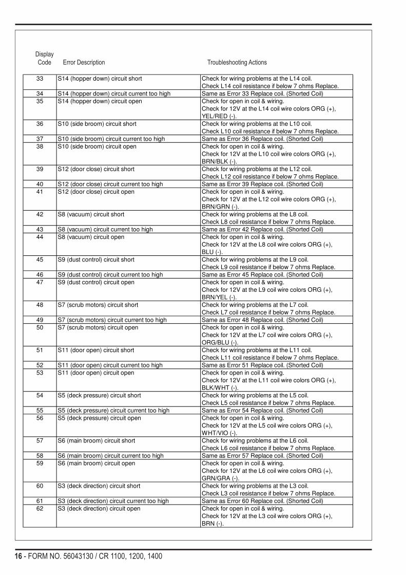
Display Code Error Description Troubleshooting Actions
33 S14 (hopper down) circuit short Check for wiring problems at the L14 coil.
Check L14 coil resistance if below 7 ohms Replace.
34 S14 (hopper down) circuit current too high Same as Error 33 Replace coil. (Shorted Coil)
35 S14 (hopper down) circuit open Check for open in coil & wiring.
Check for 12V at the L14 coil wire colors ORG (+),
YEL/RED (-).
36 S10 (side broom) circuit short Check for wiring problems at the L10 coil.
Check L10 coil resistance if below 7 ohms Replace.
37 S10 (side broom) circuit current too high Same as Error 36 Replace coil. (Shorted Coil)
38 S10 (side broom) circuit open Check for open in coil & wiring.
Check for 12V at the L10 coil wire colors ORG (+),
BRN/BLK (-).
39 S12 (door close) circuit short Check for wiring problems at the L12 coil.
Check L12 coil resistance if below 7 ohms Replace.
40 S12 (door close) circuit current too high Same as Error 39 Replace coil. (Shorted Coil)
41 S12 (door close) circuit open Check for open in coil & wiring.
Check for 12V at the L12 coil wire colors ORG (+),
BRN/GRN (-).
42 S8 (vacuum) circuit short Check for wiring problems at the L8 coil.
Check L8 coil resistance if below 7 ohms Replace.
43 S8 (vacuum) circuit current too high Same as Error 42 Replace coil. (Shorted Coil)
44 S8 (vacuum) circuit open Check for open in coil & wiring.
Check for 12V at the L8 coil wire colors ORG (+),
BLU (-).
45 S9 (dust control) circuit short Check for wiring problems at the L9 coil.
Check L9 coil resistance if below 7 ohms Replace.
46 S9 (dust control) circuit current too high Same as Error 45 Replace coil. (Shorted Coil)
47 S9 (dust control) circuit open Check for open in coil & wiring.
Check for 12V at the L9 coil wire colors ORG (+),
BRN/YEL (-).
48 S7 (scrub motors) circuit short Check for wiring problems at the L7 coil.
Check L7 coil resistance if below 7 ohms Replace.
49 S7 (scrub motors) circuit current too high Same as Error 48 Replace coil. (Shorted Coil)
50 S7 (scrub motors) circuit open Check for open in coil & wiring.
Check for 12V at the L7 coil wire colors ORG (+),
ORG/BLU (-).
51 S11 (door open) circuit short Check for wiring problems at the L11 coil.
Check L11 coil resistance if below 7 ohms Replace.
52 S11 (door open) circuit current too high Same as Error 51 Replace coil. (Shorted Coil)
53 S11 (door open) circuit open Check for open in coil & wiring.
Check for 12V at the L11 coil wire colors ORG (+),
BLK/WHT (-).
54 S5 (deck pressure) circuit short Check for wiring problems at the L5 coil.
Check L5 coil resistance if below 7 ohms Replace.
55 S5 (deck pressure) circuit current too high Same as Error 54 Replace coil. (Shorted Coil)
56 S5 (deck pressure) circuit open Check for open in coil & wiring.
Check for 12V at the L5 coil wire colors ORG (+),
WHT/VIO (-).
57 S6 (main broom) circuit short Check for wiring problems at the L6 coil.
Check L6 coil resistance if below 7 ohms Replace.
58 S6 (main broom) circuit current too high Same as Error 57 Replace coil. (Shorted Coil)
59 S6 (main broom) circuit open Check for open in coil & wiring.
Check for 12V at the L6 coil wire colors ORG (+),
GRN/GRA (-).
60 S3 (deck direction) circuit short Check for wiring problems at the L3 coil.
Check L3 coil resistance if below 7 ohms Replace.
61 S3 (deck direction) circuit current too high Same as Error 60 Replace coil. (Shorted Coil)
62 S3 (deck direction) circuit open Check for open in coil & wiring.
Check for 12V at the L3 coil wire colors ORG (+),
BRN (-).

FORM NO. 56043130 / CR 1100, 1200, 1400 - 17
Display Code Error Description Troubleshooting Actions
63 S4 (deck direction) circuit short Check for wiring problems at the L4 coil.
Check L4 coil resistance if below 7 ohms Replace.
64 S4 (deck direction) circuit current too high Same as Error 63 Replace coil. (Shorted Coil)
65 S4 (deck direction) circuit open Check for open in coil & wiring.
Check for 12V at the L4 coil wire colors ORG (+),
YEL/BLU (-).
66 S1 (deck & squeegee lift) circuit short Check for wiring problems at the L1 coil.
Check L1 coil resistance if below 7 ohms Replace.
67 S1 (deck & squeegee lift) circuit current too high Same as Error 66 Replace coil. (Shorted Coil)
68 S1 (deck & squeegee lift) circuit open Check for open in coil & wiring.
Check for 12V at the L1 coil wire colors ORG (+),
BLU/WHT (-).
69 S2 (squeegee direction) circuit short Check for wiring problems at the L2 coil.
Check L2 coil resistance if below 7 ohms Replace.
70 S2 (squeegee direction) circuit current too high Same as Error 69 Replace coil. (Shorted Coil)
71 S2 (squeegee direction) circuit open Check for open in coil & wiring.
Check for 12V at the L2 coil wire colors ORG (+),
ORG/RED (-).
72 Side broom actuator circuit short Check for short in wires or motor.
73 Side broom actuator circuit current too high Check for binding of linkage.
74 Side broom actuator circuit open See service manual section flowcharts.
75 Engine speed actuator circuit short (diesel) Check for short at motor and wires.
76 Engine speed actuator circuit current too high
(diesel) Check for binding of linkage.
77 Engine speed actuator circuit open (diesel) Check for open in wires or motor.
78
79
80
18 - FORM NO. 56043130 / CR 1100, 1200, 1400
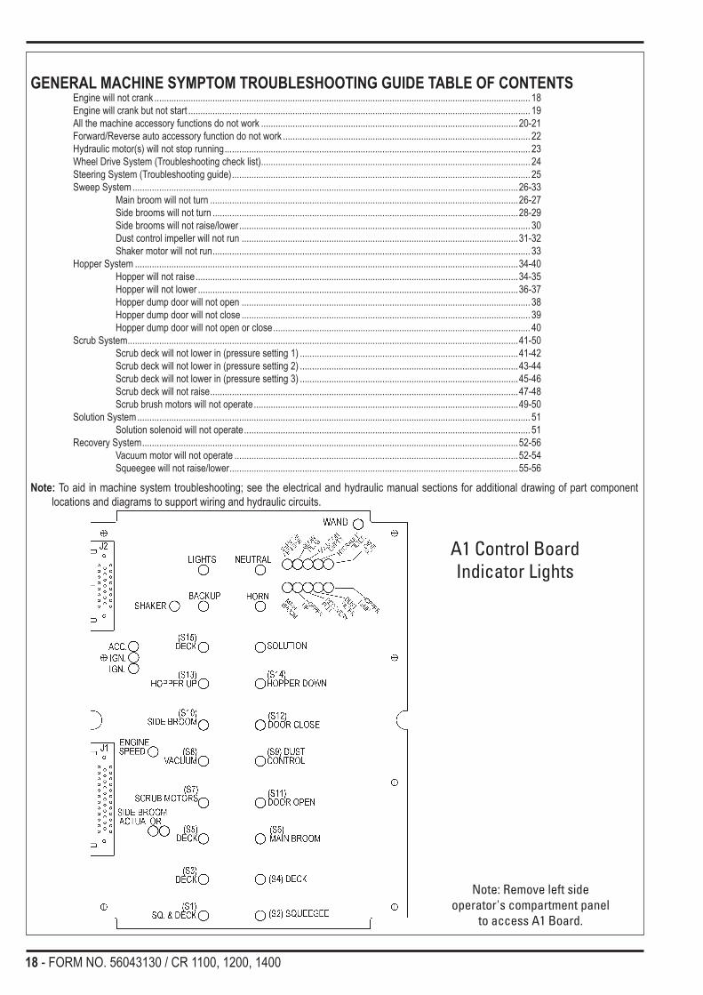
GENERAL MACHINE SYMPTOM TROUBLESHOOTING GUIDE TABLE OF CONTENTSEngine will not crank ........................................................................................................................................................... 18Engine will crank but not start ............................................................................................................................................. 19All the machine accessory functions do not work ..........................................................................................................20-21Forward/Reverse auto accessory function do not work ...................................................................................................... 22Hydraulic motor(s) will not stop running .............................................................................................................................. 23Wheel Drive System (Troubleshooting check list) ............................................................................................................... 24Steering System (Troubleshooting guide) ........................................................................................................................... 25Sweep System ...............................................................................................................................................................26-33 Main broom will not turn ...............................................................................................................................26-27 Side brooms will not turn ..............................................................................................................................28-29 Side brooms will not raise/lower ........................................................................................................................ 30 Dust control impeller will not run ..................................................................................................................31-32 Shaker motor will not run ................................................................................................................................... 33Hopper System ..............................................................................................................................................................34-40 Hopper will not raise .....................................................................................................................................34-35 Hopper will not lower ....................................................................................................................................36-37 Hopper dump door will not open ....................................................................................................................... 38 Hopper dump door will not close ....................................................................................................................... 39 Hopper dump door will not open or close .......................................................................................................... 40Scrub System .................................................................................................................................................................41-50 Scrub deck will not lower in (pressure setting 1) ..........................................................................................41-42 Scrub deck will not lower in (pressure setting 2) ..........................................................................................43-44 Scrub deck will not lower in (pressure setting 3) ..........................................................................................45-46 Scrub deck will not raise ...............................................................................................................................47-48 Scrub brush motors will not operate .............................................................................................................49-50Solution System .................................................................................................................................................................. 51 Solution solenoid will not operate ...................................................................................................................... 51Recovery System ...........................................................................................................................................................52-56 Vacuum motor will not operate .....................................................................................................................52-54 Squeegee will not raise/lower .......................................................................................................................55-56
Note: To aid in machine system troubleshooting; see the electrical and hydraulic manual sections for additional drawing of part component locations and diagrams to support wiring and hydraulic circuits.
A1 Control Board Indicator Lights
Note: Remove left side operator's compartment panel
to access A1 Board.

FORM NO. 56043130 / CR 1100, 1200, 1400 - 19
OPERATOR’S COMPARTMENTA Low Fuel Indicator (LP)B Horn Switch* Horn ON IndicatorC Engine Service Indicator (triggered by
ECU)D Headlight Switch* Headlight ON IndicatorE Glow Plug Indicator (Diesel / Release key
after indicator turns OFF)F Hydraulic Filter Plugged IndicatorG Engine Speed Switch* Engine Speed Switch IndicatorH Scrub Pressure Decrease Switch* Scrub Pressure Decrease IndicatorI Scrub Pressure Increase Switch* Scrub Pressure Increase IndicatorJ Scrub Pressure & Error Code Display
K Solution Switch* Solution System IndicatorL Low Solution Indicator (8-10 gal.)M Recovery Tank Full IndicatorN Side Broom DOWN/ON Switch* Side Broom ON IndicatorO Main Broom ON IndicatorP Light SensorQ Shaker Switch* Shaker Indicator (left)* Dust Filter Plugged Indicator (right)R Open Dump Door Switch* Open Dump Door IndicatorS Hopper Open IndicatorT Hopper Overtemp IndicatorU Close Dump Door Switch* Close Dump Door Indicator
V Lower Hopper Switch* Lower Hopper IndicatorW Raise Hopper Switch* Raise Hopper IndicatorX Dust Control Switch* Dust Control ON IndicatorY Side Broom UP/OFF Switch* Side Broom OFF IndicatorZ Vacuum System Switch* Vacuum System IndicatorAA Scrub System OFF Switch* Scrub System OFF IndicatorBB Coolant Temperature GaugeCC Oil Pressure GaugeDD Fuel Gauge (Gas / Diesel)EE VoltmeterFF Hour meter
KNOW YOUR MACHINE
A2 Control Panel Assembly
TEMPF/C
VOLTSFUEL
OILPSI/BAR
HOURS 1/10250
175
12050
75100
10050
01
38
F
E1/2
18
1310
+-
AB
C
D
EF G
BBCC
DD
EE
IJ
H
K
L
MN
OP
QR
S
T
UV
W
X
Y
ZAA
FF

20 - FORM NO. 56043130 / CR 1100, 1200, 1400
TROUBLESHOOTING GUIDEPossible Symptom1 Engine will not crank
Electrical Control CircuitNote 1: To test the key switch must be in the START position and foot pedal in neutral.Note 2: Before troubleshooting check the F4 (15 amp) circuit breaker location under steering column.Note 3: Check for 12V at the F4 machine circuit breaker. If no input voltage at the GRN/BLK wire, repair or replace wiring or key switch.Service Adjustment Note: A drive pedal sensor setting that is set too low will not target (match) the drive pedal neutral return position (dead-band too narrow) and the engine will not start. Too high of a setting will increase the neutral range (dead-band too wide) and delay the activation of turning on the auto sweep and scrub functions when the drive pedal is moved out of an excessively wide programmed neutral range.
Note 4: A new pedal sensor must be programmed for its neutral position and dead-band setting, follow instructions shown on this page.
Repair or replace relay or wir-ing. Is there 12 volts at the
BLU/PNK?
Replace engine fuse box start relay. Loca-tion of fuse box on top of engine
No
No
At the K4 relay do you have12 volts at the BLU/PNK?
Yes
No
Engine will still not crank?
No
Yes
No
Engine will not crank
Is the neutral indicator lightoff at the A1 board?
The pedal is not returning toits neutral state. Repair anymechanical problems to the
foot pedal linkage orhydroback.
Does the light go off?
Replace the drive pedal sen-sor. Does the light go off?
(See note 4)
Reset drive pedal sensor dead band setting. Sensor has arange of 1-9 factory setting is 2-5.
Turn key switch off, press and hold the engine speedswitch then turn the key on. Setting should be at 2-5. To
change setting press the speed switch, To exit turn key off.Does the light go off?
No
Replace the A1 control board.Does the engine crank?
Yes
Yes
Yes
Check for 12 volts at WHT wirelocated on starter solenoid withthe key in the start position. Ifyes repair or replace starter.

FORM NO. 56043130 / CR 1100, 1200, 1400 - 21
TROUBLESHOOTING GUIDEPossible Symptom1 Engine will crank but not start
Electrical Control CircuitNote 1: Check for 12V at the F3 machine circuit breaker. If no input voltage at the ORG/GRN wire repair or replace wiring or key switch.Note 2: Check the fuel supply (empty tank).
Check the 5 Amp fuse (F1)see engine system Figure 2
fuse box.
Engine will crank butnot start
Replace the F3 (10 Amp)circuit breaker
Check for 12V (+) at the X9 harnessconnector (location by engine
starter) pin “A” wire color pink.
Repair or replace wiringback to the F3 circuit
breaker
Check the continuity ofthe F3 circuit breaker
Replace the F15 Amp fuse.
Select fuel typeGasoline LP
Check for 12V atfuel pump
Check fuel pumpF4 fuse (15 Amp)
Replace F4 fuse(15 Amp)
-Check fuel filter(pickup)
-Check fuel pumpoutput. Repair or
replace
• Engine still willnot start
-Replace the fuelpump relay.
• Engine still willnot start
Check for 12V atthe fuel lock-off
Repair wiring tofuel lock-off.
-Replace fuellock-off
• Engine still willnot start
See engine fuelsystem manual
Yes
No
Yes
No
No
Yes
No
Yes
No
Yes
No
Yes

22 - FORM NO. 56043130 / CR 1100, 1200, 1400
TROUBLESHOOTING GUIDEPossible Symptom1 All the machine accessory system’s functions (operations) do not work. Example: no brush, broom, vacuum and hopper functions etc.
Part A: Electrical Control CircuitNote: Do all testing with Key Switch ON.
All the machine accessorysystem’s functions
(operations) do not work
When key is first turnedon do all the A2 display
panel lights momentarilyturn on?
Test for the 12V output fromA1 wires WHT/BRN & BLK
Check the power & commu-nication inputs to A2
•Test circuit continuity ofwires BRN/BLU & GRN/BLU
•Test for 12V power inputwires WHT/BRN & BLK
Sub a new A2 Display Panel
Machine system fixed allfunctions now operational
See Hydraulic Load CircuitPart B
Repair or replacedefective wiring
Replace A1 MainController
No
No
Test for the 12V powerinput to A1, wires VIO &
BLK
•Check for a defective F2circuit breaker (15A)
•An open in either the circuitbattery (pos.) VIO wire or BLK
battery (neg.) wire
No
Repair or replace defectiveparts.
Do the A2 panel lights nowfunction?
No
Yes
Replace the A1 Controller
No
Yes
YesNo
No
Yes

FORM NO. 56043130 / CR 1100, 1200, 1400 - 23
TROUBLESHOOTING GUIDEPossible Symptom1 All the machine accessory system’s functions (operations) do not work. Example: no brush, broom, vacuum, and hopper functions etc.
Part B: Hydraulic Load CircuitNote: Do all testing with Key Switch ON.
*Note: See hydraulic manual section for system specifications (relief valves, pumps, motors etc.).
No No
Yes
Yes
Have you lost both ofthe machine hydraulic
systems,Drive and Accessory
Does wheel drive motormove the machine
See wheel drive systemtroubleshooting
Defective drive couplerbetween engine and
propulsion pump.Repair or replace the
coupler
Yes
No HydraulicAccessories Work
Do some accessoryfunctions work? If sosee chart belowfor
appropriate pump circuit
*Pump circuit 2 poor or noperformance of steeringsystem, dump door, hop-per lift, engine fan, dustcontrol and side brooms
Failure of the propulsioncoupler input to the frontaccessory pump repair
or replace the faultypump
*Pump circuit 3 poor orno performance of scrub
motors, scrub deckup/down and squeegee
up/down
*Pump circuit 1 poor orno performance of main
broom, vac fan andhydraulic charge line
Adjust, clean or replace#1A relief valve.Does the system
function?
Adjust, clean or replace#1 relief valve.
Does the systemfunction?
Adjust, clean or replace#1B relief valve.Does the system
function?
Repair or replace pump Repair or replace pumpRepair or replace pump
Yes YesYes
No NoNo
No

24 - FORM NO. 56043130 / CR 1100, 1200, 1400
TROUBLESHOOTING GUIDEPossible Symptom1 Forward/Reverse auto accessory functions do not work or activate slowly (do not function properly). Examples: Main broom, side brooms,
scrub motors, vacuum motor and dust control motor.
Electrical Control CircuitNote: Do all testing with the key switch ON, hopper lowered and drive pedal activated (forward/reverse).Service Adjustment Note: A drive pedal sensor setting that is set too low will not target (match) the drive pedal neutral return position (dead-band too narrow) and the engine will not start. Too high of a setting will increase the neutral range (dead-band too wide) and delay the activation of turning on the auto sweep and scrub functions when the drive pedal is moved out of an excessively wide programmed neutral range.
Machine drive autofunction does not work
Place the pedal in forward orreverse position. Check on theA1 control board. Is the green
neutral indicator light on?
Is the hopper yellow indicatorlight on at the A1 board?
Adjust or replacemagnetic switch
S12.Does light come
on?
No
Yes Yes
Replace the A1 Control BoardReplace pedal
sensor or wiring(switch is open).
No
Yes
No
ReplaceA1 boardNo
Reset drive pedal sensor dead band set-ting. Sensor has a range of 1-9
factory setting is 2-5.Turn key switch off, press and hold the
engine speed switch then turn the key on.Setting should be at 2-5. To change setting
press the speed switch, To exit turn keyoff. Does the light come on and
auto functions operate?

FORM NO. 56043130 / CR 1100, 1200, 1400 - 25
TROUBLESHOOTING GUIDEPossible Symptom1 Hydraulic motor(s) will not stop running.Note 1: Do all testing with the key switch ON and all machine functions OFF.Note 2: If optional “Vacuum Wand Kit” is installed and its switch is activated the vacuum motor will turn on when the engine is started.
Hydraulic motor(s) willnot stop running.
Is the indicator light OFF atthe A2 display panel for the
malfunctioning motor?
Replace theA2 touch pad.
Locate the malfunctioningmotors hydraulic cartridge
valve, clean or replace.
See hydraulic system’stroubleshooting section for
locations.
Yes
No
Is the green indicator lightfor the malfunctioning
motor OFF at A1 controlboard?
Replace theA1 control board.No
Yes

26 - FORM NO. 56043130 / CR 1100, 1200, 1400
WHEEL DRIVE SYSTEM
Symptom Possible CauseWheel drive functions sluggish or slow • Engine not operating in high-speed setting or engine speed is too
slow (2400 RPM). • Air in hydraulic fluid (loose fittings). • Propulsion pump inlet restriction (cavitation of hydraulic fluid). • Worn drive wheel motor (*test working pressure & wheel drive
speed).Wheel drive in one direction only • Inspect propulsion pump relief valves for: A. Debris that allows valve seat to be held open, B. Damaged or weak valve spring, C. Valve unloading pressure setting to low for application.
No wheel drive in either direction • Check that pump bypass valve (tow valve) is in correct position. • Check connection of foot pedal linkage (cable assembly) to
propulsion pump arm. • Worn propulsion pump (*test output oil volume with a flow meter). • Defective propulsion pump charge circuit. Test its relief valve
pressure setting (75-150 psi). • Worn or damaged wheel drive motorNo hydraulic system functions drive or accessory • Check for a damaged coupling connection from the engine to the
pump shaft input.
*Note: See in the hydraulic specification manual section, tables that list all the individual system component values (pressures, flows, rpms etc).
Hydraulic Wheel Drive System
Troubleshooting Check List

FORM NO. 56043130 / CR 1100, 1200, 1400 - 27
STEERING SYSTEM
Steering System Hydraulic Diagram
TROUBLESHOOTING GUIDE Problem Possible cause Slow steering, hard steering or loss of Priority flow divider not providing 1.75 GPM. Power assist. 1450 PSI relief valve open or malfunctioning.
Steering wandering. Rack and pinion worn or out of adjustment. Loose or leaking cylinder piston.
Steering control unit worn.
Steering wheel turns freely Problem with steering column without moving wheel. Shaft or spline.
Steering binding. Rack and pinion worn or out of adjustment.
Steer cylinder loose.
STEERING SYSTEM TROUBLESHOOTING OVERVIEWSee Figure 1. A hydraulic steering unit, with the steering wheel mounted to it, controls the rack cylinder. The steering unit runs off the middle gear pump of the auxiliary pump assembly. The oil flows through a priority divider built into the pressure relief block assembly that divides the pump output and reduces the oil flow to 1.75 GPM for the steering system. There is a check valve built into the steering unit that allows for manual steering if there is no hydraulic oil flow to the unit. The relief valve for the steering system is located in the steering unit and is set to open at 1450 PSI.
1.75 GPM
6.0 GPM
RESERVOIR
COOLERFILTER
2400 PSI
MAN
IFOL
D
STEERCYLIN
DER2
x6
STEERING UNIT
ENGINE FAN
1450 PSI
4.5.323
LR
TE
25 PSI
.58
C D
P
P2 P3 T2

28 - FORM NO. 56043130 / CR 1100, 1200, 1400
SWEEPING SYSTEMTROUBLESHOOTING GUIDEPossible Symptom1 Main broom will not turn.
Part A: Electrical Control CircuitNote: Do all testing with Key Switch ON, Broom Lever lowered, Hopper closed, Broom Door open and the Drive Pedal activated (placed in forward or reverse).
Main broom will not turn
On the A1 - Board, is theS6 broom motor relay
indicator light on?
Check the adjustment &operation of the S16 broomswitch. Switch continuity,is open with broom lever
lowered.
Check for 12V at the L6 sole-noid coil, wire colors
GRN/GRA (-) & ORG (+).
Check both wires forcontinuity. Repair or
replace defectivewire(s)
Does broom run?
Check the L6 coil resistanceit should read 7-9 ohms.
Replace (L6) coil (checksopen or shorted).Does broom run?
See Part B main broommotor hydraulic load circuit
Yes
Yes
Yes
No
No
No
Replace the A1 Main Con-troller. Does broom run?
Yes
Clean, Adjust orreplace the magneticbroom switch (S16)Does broom run?
No No
No
No
No

FORM NO. 56043130 / CR 1100, 1200, 1400 - 29
SWEEPING SYSTEMTROUBLESHOOTING GUIDEPossible Symptom1 Main broom will not turn.
Part B: Hydraulic Load CircuitNote: Do all testing with the Broom Lever lowered, Hopper closed, Broom Door open, the Drive Pedal forward/reverse, and engine running at (2400 RPM) high speed.
No
Replace defective spoolvalve L6.
Does motor operate?
Replace motor
No No
NoNo
Yes
Inspect the main broom forpossible mechanical bind-ing, damaged broom lug
inserts and debris wrappedaround broom or broom
motor.
Remove debris and makeany repairs or replace
damaged parts.Does the main broom
turn?
Yes
Main broomwill not turn
See troubleshooting sec-tion titled, No hydraulic
accessories work.
Remove and disassembleL6 broom motor spool
valve (cartridge) inspect,clean and reinstall.
Does the broom function?
Does the vacuum motoron pump circuit 1 work?

30 - FORM NO. 56043130 / CR 1100, 1200, 1400
SWEEPING SYSTEMTROUBLESHOOTING GUIDEPossible Symptom1 Side brooms will not turn
Part A: ElectricalNote: Do all testing with the key switch ON, the hopper closed, main broom lowered. Side broom lower switch pressed on the display panel and the drive pedal activated.
Side brooms will not turn
Press the side broom lowerswitch, (located on the
A2 display panel).Is its green indicator light on?
Substitute a new A2display panel
Do side brooms operate?
Check for 12 volts at L10 sidebroom motors coil.
Wire colors(+) ORG
(-) BRN/BLK
Repair or replace L10coil wiring.
Do the side broommotors operate?
Check L10 coil resistance(9 ohm)
Repair or replace L10coil.
Do the side broommotors operate?
See Hydraulic side broomtroubleshooting section
Part B
Yes
Yes
Yes
No
No
No
On the A1 board is the S10side brooms motor relay
indicator light on?
Replace A1 controlboard
Do the side broommotors operate?
No
Yes

FORM NO. 56043130 / CR 1100, 1200, 1400 - 31
SWEEPING SYSTEMTROUBLESHOOTING GUIDEPossible Symptom1 Side brooms will not turn
Part B: HydraulicNote: Do all testing with the engine running (2400 rpm), the hopper closed, main broom lowered. Side broom lower switch pressed and the drive pedal activated.
Side broomswill not turn
Clean and repair motors.Do they turn?
Replace defectivespool valve L10.
Do the side broom motors run?
Repair or replace sidebroom motors
Remove and disassemble L10spool valve (cartridge). Inspect
clean and reinstall.Do the side broom motors run?
Yes
Do some pump circuit 2funtion work steering,
engine fan, dust control?
Inspect for possible debriswrapped around motor shafts.No
See hydraulic loadtrouble shooting, Noaccessories work.
No
Yes
No
No
No
Yes

32 - FORM NO. 56043130 / CR 1100, 1200, 1400
SWEEPING SYSTEMTROUBLESHOOTING GUIDEPossible Symptom1 Side broom lift actuator motor will not raise or lower
Electrical CircuitNote: Do all testing with the key switch turned ON and main broom lever lowered.
Side brooms do not raise orlower
Press one at a time the sidebroom ON (lower) and OFF
(raise) buttons on the A2 panel.Do both the green indicator
lights turn on.
Substitute a new A2 displaypanel.
Do the brooms now raise orlower?
Press the side broom OFF(raise) button and check on
the A1 control board to see ifits green relay indicator light
comes on.
Replace the A1 controlboard. Do brooms now raise
or lower?
Test for 12V at the M4actuator motor.
To lower wire colors(-) WHT & (+) RED.
To raise (-) BLK & (+) WHT
Repair or replace defectiveconnector and or wiring. Do
brooms raise or lower?
Yes
Yes
Yes
No
No
No
Press the side broom ON(Lower) button and check onthe A1 control board to see if
its red relay indicator lightcomes on.
No
Yes No
No
Replace the M4 side broom liftactuator motor.
No

FORM NO. 56043130 / CR 1100, 1200, 1400 - 33
SWEEPING SYSTEMTROUBLESHOOTING GUIDEPossible Symptom1 Dust control impeller will not run
Part A: ElectricalNote: Do all testing with the key switch ON, and the hopper closed. Also dust control switch must be activated on the display panel and the drive pedal must be activated (placed in forward or reverse).
Dust control impellermotor will not run
Press the dust control switch,(located on the A2 display
panel).Is its green indicator light on?
Substitute a newA2 display panel.
Does impeller operate?
Check for 12V at L9 impellermotor coil.Wire colors
(+) ORG(-) BRN/YEL
Repair or replace L9 coilwiring.
Does impeller motoroperate?
Check L9 coil resistance(9 ohm)
Repair or replace L9coil.
Does impeller motoroperate?
See Hydraulic impellermotor troubleshooting
section Part B
Yes
Yes
Yes
No
No
No
On the A1 board is the S9impeller motor relay light
on?
Replace A1 controlboard.
Does impeller motoroperate?
No
Yes

34 - FORM NO. 56043130 / CR 1100, 1200, 1400
SWEEPING SYSTEMTROUBLESHOOTING GUIDEPossible Symptom1 Dust control impeller will not run
Part B: HydraulicNote: Do all testing with the engine running (2400 rpm). Also dust control switch must be activated on the display panel and the drive pedal must be activated.
Dust control impellerwill not run
Remove and disassembleL9 spool valve (cartridge)
inspect, clean and reinstallDoes the impeller motor run?
Replace defective spoolvalve L9 (located on
impeller motor).
Does it operate?
Repair or replace impellermotor
No
No

FORM NO. 56043130 / CR 1100, 1200, 1400 - 35
SWEEPING SYSTEMTROUBLESHOOTING GUIDEPossible Symptom1 Shaker motor will not run
Electrical CircuitNote1: Before testing first confirm that the 10Amp F7 circuit breaker is good.Note2: Do all testing with the key switch turned ON.
Shaker motor will not run
Press the shaker button on theoperator A2 panel. Is the upper
left green indicator light on?
Substitute a new A2 displaypanel.
Does shaker motor operate?
Check for 12V at the K3 shakerrelay coil, wire colors (-) GRN
& (+) ORG
Repair or replace wiring tocoil.
Does shaker motor operate?
Check the K3 coil resistanceshould measure
370 Ohms + or - 10%
Replace the defectiveK3 relay.
Does shaker motor operate?
Yes
Yes
Yes
No
No
No
Press shaker switch buttonand check on the A1 control
board to see if the shakerrelay green indicator light is
on.
Replace A1 control board.Does shaker motor
operate?No
Yes
Check for 12V at the shakermotor, wire colorsBLU/GRN & BLK
Replace the defective K3relay or wiring.
Does shaker motor operate?
Yes
NoTest for 12V (+) at the K3 relay
load terminals•(output #87) BLU/GRN to
battery ground•(input #30) BLU/YEL to bat. GND
Repair or replacemotor wiring.
Does shaker motor operate?
Yes
No
Replace the M2 shaker motor
No
No
No
No
No
No

36 - FORM NO. 56043130 / CR 1100, 1200, 1400
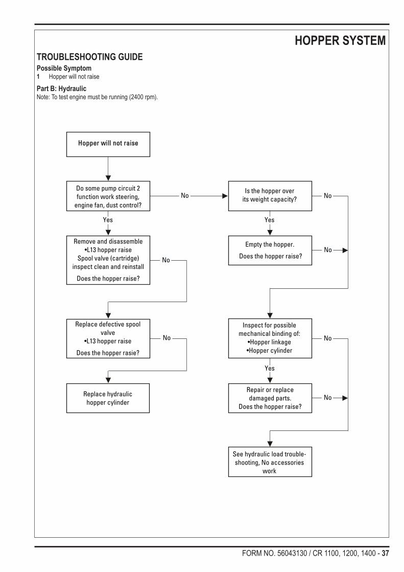
HOPPER SYSTEMTROUBLESHOOTING GUIDEPossible Symptom1 Hopper will not raise
Part A: ElectricalNote: Do all testing with the key switch turned ON, and the hopper raise switch pressed on the operator display panel.
Hopper will not raise
Press and hold hopper raiseswitch. Is its green indicatorlight on the A2 display panel
Substitute a new A2display panel.
Does the hopper raise?
Check for 12 volts atL13 hopper raise coil.
Wire colors(+) ORG
(-) RED/GRY
Repair or replace L13coil wiring.
Does the hopper raise?
Check for coil resistanceat L13 (9 ohm)
Repair or replace L13coil.
Does the hopper raise?
See Hydraulic hopper lifttroubleshooting section
Part B
Yes
Yes
Yes
No
No
No
Press and hold hopper raisebutton. On the A1 board is theS13 relay green indicator lighton? Note relay S12 will be on
momentary
Replace A1 controlboard.
Does the hopper raise?No
Yes
No
No
No
No
FORM NO. 56043130 / CR 1100, 1200, 1400 - 37
HOPPER SYSTEMTROUBLESHOOTING GUIDEPossible Symptom1 Hopper will not raise
Part B: HydraulicNote: To test engine must be running (2400 rpm).
Empty the hopper.
Does the hopper raise?
Inspect for possiblemechanical binding of:
•Hopper linkage•Hopper cylinder
Do some pump circuit 2function work steering,
engine fan, dust control?
No
Repair or replacedamaged parts.
Does the hopper raise?
See hydraulic load trouble-shooting, No accessories
work
No
No
Remove and disassemble•L13 hopper raise
Spool valve (cartridge)inspect clean and reinstall
Does the hopper raise?
Yes
Replace defective spoolvalve
•L13 hopper raise
Does the hopper rasie?
Is the hopper overits weight capacity?
Hopper will not raise
Replace hydraulichopper cylinder
No
No
Yes
No
No
Yes

38 - FORM NO. 56043130 / CR 1100, 1200, 1400
HOPPER SYSTEMTROUBLESHOOTING GUIDEPossible Symptom1 Hopper will not lower
Part A: ElectricalNote: Do all testing with the key switch turned ON, and the hopper lower switch pressed on the display panel.
Hopper will not lower
Press and hold hopper lowerswitch. Is its green indicator
light on?
Substitute a new A2display panel.
Does the hopper lower?
Check for 12 volts atL14 hopper lower coil.
Wire colors(+) ORG
(-) YEL/RED
Repair or replace L14coil wiring.
Does the hopper lower?
Check for coil resistanceat L14 (9 ohm)
Repair or replace L14coil.
Does the hopper lower?
See Hydraulic hopper lowertroubleshootingsection Part B
Yes
Yes
Yes
No
No
No
Press and hold hopper lowerbutton is the green light on the
A1 board S14Note relay S12 will be on
momentary
Replace A1 controlboard.
Does the hopper lower?No
Yes
No
No
No
No
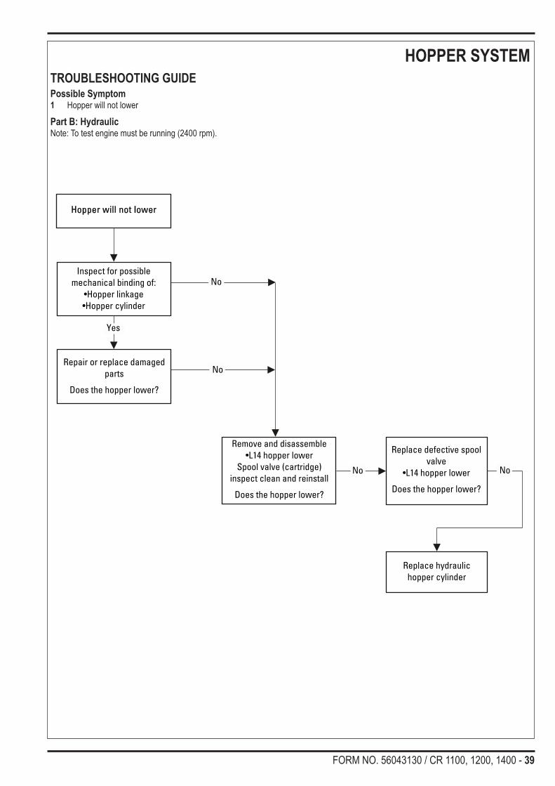
FORM NO. 56043130 / CR 1100, 1200, 1400 - 39
HOPPER SYSTEMTROUBLESHOOTING GUIDEPossible Symptom1 Hopper will not lower
Part B: HydraulicNote: To test engine must be running (2400 rpm).
Repair or replace damagedparts
Does the hopper lower?
Remove and disassemble•L14 hopper lower
Spool valve (cartridge)inspect clean and reinstall
Does the hopper lower?
Replace defective spoolvalve
•L14 hopper lower
Does the hopper lower?
No
Inspect for possiblemechanical binding of:
•Hopper linkage•Hopper cylinder
Hopper will not lower
Replace hydraulichopper cylinder
No
No
No
Yes

40 - FORM NO. 56043130 / CR 1100, 1200, 1400
HOPPER SYSTEMTROUBLESHOOTING GUIDEPossible Symptom1 Hopper dump door will not open in dump mode.
Part A: Note: Do all testing with Key Switch ON, hopper raised (engine must be run to raise hopper).
Press and hold dump dooropen switch. Is the green light
on the A1 board S11 relay.
Check for 12 volts at L11Dump Door coil. Wire color
(+) ORN, (-) BLK/WHT
Check for coil resistance atL11 (9 ohm)
See hydraulic dump doortroubleshooting section
Part B
Repair or replace L11 coil
No
No
Yes
No
Yes
Replace theA1 Control board
No
Yes
Yes
Repair or replace L11 coilwiring
No
Yes
Substitute a new A2 Displaypanel. Does dump door
operate?
Repair or replace (S12)switch wiring.
Does door open?
Yes
Yes
No
Dump Door will not open
Check if the hopper raiseindicator light is flashing
on A2 panel
Check continuity andadjustment of hopper raise
switch (S12)Note: Switch will check
open when hopper israised
Repair or replace (S12)switch.
Press and hold dump dooropen switch, is its green
indicator light on
Check (S12) switch wiringfor a short
Replace A2 control paneldisplay
No
No

FORM NO. 56043130 / CR 1100, 1200, 1400 - 41
HOPPER SYSTEMTROUBLESHOOTING GUIDEPossible Symptom1 Hopper dump door will not close in dump mode.
Part A: Note: Do all testing with Key Switch ON, hopper raised (engine must be run to raise hopper).
Dump Door will not close
Check if the hopper raiseindicator light is flashing
on A2 panel.
Press and hold dump doorclosed button and observe onthe A1 board to see if the S12
relay light is on.
Check for 12 volts at L12Dump Door coil. Wire color
(+) ORN, (-) BLK/WHT
Check for coil resistance atL12 (9 ohm)
See hydraulic dump doortroubleshooting section
Part B
Check continuity andadjustment of hopper raise
magnetic switch (S12)Note: Switch will check
open when hopper israised.
Repair or replace L12 coil.Does the door operate?
No
No
Yes
Press and hold hopperdoor close switch. Is itsgreen indicator light on?
Check (S12) switch wiringfor a short.
No
Yes
Replace the A1 Controlboard.
Does the door operate?
No
Yes
Yes
No
Repair or replace L12 coilwiring.
Does the door operate?
Repair or replace (S12)switch
No
Yes
Substitute a new A2 Displaypanel. Does dump door
operate?
Repair or replace (S12)switch wiring.
No
Yes
Yes
NoNo
No
No
No

42 - FORM NO. 56043130 / CR 1100, 1200, 1400
HOPPER SYSTEMTROUBLESHOOTING GUIDEPossible Symptom1 Hopper dump door will not open or close when in dump mode.
Part B: Note: To test engine must be running in high speed (2400 rpm).
Dump Doorwill not operate
Inspect for possiblemechanical binding of:
•Dump door•Dump door linkage•Dump door cylinder
Do some pump circuit 2functions work?
Steering, engine fan, dustcontrol and side broom
motor(s).
No
Yes
Repair or replace dumpdoor, dump door linkage,
dump door cylinder. Doesthe door function?
See hydraulic load trou-bleshooting, section
titled, “No Accessorieswork”.
No
Remove and disassemble•L11 door open
•L12 door closedSpool valve (cartridge)
inspect clean and reinstall.
Does the door function?
Yes
Replace defective spoolvalve.
•L11 door open•L12 door closed
Does the door function?
NoRepair or replace
door cylinderNo
No

FORM NO. 56043130 / CR 1100, 1200, 1400 - 43
SCRUB SYSTEMTROUBLESHOOTING GUIDEPossible Symptom1 Scrub deck will not lower
Part A: Electrical Control CircuitNote: Do all testing with the key switch ON, scrub deck pressure set on (1) by depressing the scrub decrease switch on the A2 display panel.
Scrub deck will not lower (1)
Press and hold scrubdecrease switch (-).
Is its green indicator light on?
Substitute a new A2display panel.
Does the deck lower?
Check for 12 volts at coil• L4 (+) ORG (-) YEL/BLU.
Repair or replacedefective coil wiring.
Does the deck lower?
Check for coil resistanceat L4 (9 ohm)
Replace defective coil.
Does the deck lower?
See Hydraulic scrub decktroubleshooting section Part B
position 1.
Yes
Yes
Yes
No
No
No
Press scrub off switch then scrubdecrease switch (may need to be
cycled to observe lights) observe thegreen lights on the A1 board S3 & S4
are they on.
Replace A1 controlboard.
Does the deck lower?No
Yes
No
No
No
No

44 - FORM NO. 56043130 / CR 1100, 1200, 1400
SCRUB SYSTEMTROUBLESHOOTING GUIDEPossible Symptom1 Scrub deck will not lower or lowers partially in (1)
Part B: Hydraulic Scrub Deck (Pressure Setting 1)Note: All tests should be done with the engine running in high speed (2400 rpm).
Repair or replace damagedparts.
Does scrub deck lower?
Remove and disassemble•L4 scrub deck spool valve(cartridge) inspect, clean
and reinstall.
Does scrub deck lower?
Replace defective spoolvalve L4.
Does scrub deckfunction?
No
Inspect for possiblemechanical binding of:
•Scrub deck mount linkage•Scrub deck cylinder
Check deck pressure with ascale (1) 120 lbs. (2) 237 lbs.
(3) 385 lbs.
Replace cylinder
No
No
No
Yes
Scrub deck will not loweror lowers partially in (1)
No

FORM NO. 56043130 / CR 1100, 1200, 1400 - 45
SCRUB SYSTEMTROUBLESHOOTING GUIDEPossible Symptom1 Scrub deck will not operate in pressure setting (2)
Part A: Electrical Control CircuitNote: Do all testing with the key switch ON, scrub deck pressure set on (2) by depressing the scrub increase switch on the A2 display panel.
Scrub deck will not function inpressure setting (2)
Press and release scrubincrease switch (+) until 2 appears in
the display.Is its green indicator light on?
Substitute a new A2display panel.
Does the deck lower?
Check for 12 volts at coils•L3 (+) ORG (-) BRN•L5 (+) ORG (-) WHT/VIO•L15 (+) ORG (-) GRN/VIO
Repair or replacedefective coil wiring.
Does the deck lower?
Check for coil resistanceat L3, L5 & L15 (9 ohm)
Replace defective coil(s).
Does the deck lower?
See Hydraulic scrub deck troubleshoot-ing section Part B position 2.
Yes
Yes
Yes
No
No
No
Press the scrub off switch then scrubincrease switch (may need to be
cycled to observe lights) observe thegreen lights on the A1 board S3, S5 &
S15 are they on?
Replace A1 controlboard.
Does the deck lower?No
Yes
No
No
No
No
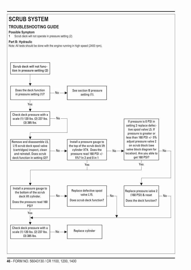
46 - FORM NO. 56043130 / CR 1100, 1200, 1400
SCRUB SYSTEMTROUBLESHOOTING GUIDEPossible Symptom1 Scrub deck will not operate in pressure setting (2)
Part B: HydraulicNote: All tests should be done with the engine running in high speed (2400 rpm).
Check deck pressure with ascale (1) 120 lbs. (2) 237 lbs.
(3) 385 lbs.
Remove and disassemble L5,L15 scrub deck spool valve(cartridges) inspect, cleanand reinstall. Does scrub
deck function in setting (2)?
Install a pressure gauge tothe top of the scrub deck lift
cylinder XT4. Does thepressure read 160 PSI +/-
5%? In 2 and 0 in 1
No
Yes
Install a pressure gauge tothe bottom of the scrub
deck lift cylinder.
Does the pressure read 160PSI?
Replace defective spoolvalve L15.
Does scrub deck function?
Replace pressure valve 2(160 PSI) & reset
Does the deck function?No
No
Check deck pressure with ascale (1) 120 lbs. (2) 237 lbs.
(3) 385 lbs.
Replace cylinderNo
Does the deck functionin pressure setting (1)?
Scrub deck will not func-tion in pressure setting (2)
No
No
Yes
See section B pressuresetting (1).
If pressure is 0 PSI insetting 2 replace defec-
tive spool valve L5. Ifpressure is greater or
less than 160 PSI +/- 5%adjust pressure valve 2
on scrub block (seevalve block diagram for
location). Are you able toget 160 PSI?
Yes
No
Yes
No No

FORM NO. 56043130 / CR 1100, 1200, 1400 - 47
SCRUB SYSTEMTROUBLESHOOTING GUIDEPossible Symptom1 Scrub deck will not operate in pressure setting (3)
Part A: Electrical Control CircuitNote: Do all testing with the key switch ON, scrub deck pressure set on (3) by depressing the scrub increase switch on the A2 display panel.
Scrub deck will not function inpressure setting (3)
Press and release scrubincrease switch (+) until 3 appears in
the display.Is its green indicator light on?
Substitute a new A2display panel.
Does the deck lower?
Check for 12 volts at coils:•L3 (+) ORG (-) BRN•L4 (+) ORG (-) YEL/BLU•L5 (+) ORG (-) WHT/VIO
Repair or replacedefective coil wiring.
Does the deck lower?
Check for coil resistanceat L3, L4 & L5 (9 ohm)
Replace defective coil(s).
Does the deck lower?
See Hydraulic scrub deck trouble-shooting section Part B position 3.
Yes
Yes
Yes
No
No
No
Press scrub off switch then scrubincrease switch (may need to be
cycled to observe lights) observe thegreen lights on the A1 board S3, S4 &
S5 are they on?
Replace A1 controlboard.
Does the deck lower?No
Yes
No
No
No
No

48 - FORM NO. 56043130 / CR 1100, 1200, 1400
SCRUB SYSTEMTROUBLESHOOTING GUIDEPossible Symptom1 Scrub deck will not operate in pressure setting (3)
Part B: HydraulicNote: All tests should be done with the engine running in high speed (2400 rpm).
Check deck pressure with ascale (1) 120 lbs. (2) 237 lbs.
(3) 385 lbs.
Remove and disassemble L15scrub deck spool valve
(cartridge) inspect, clean andreinstall. Does scrub deck
function in setting (2)?
Install a pressure gauge tothe top of the scrub deck lift
cylinder XT4. Does thepressure read 160 PSI +/-
5%? In 3 and 0 in 1
No
Install a pressure gauge tothe bottom of the scrub
deck lift cylinder.
Does the pressureread 0 PSI?
No
Check deck pressure with ascale (1) 120 lbs. (2) 237 lbs.
(3) 385 lbs.
Replace cylinderNo
Does the deck function inpressure setting (1 & 2)
Scrub deck will not func-tion in pressure setting (3)
No
No
Yes
See section B pressuresettings (1 & 2)
Replace defective spoolvalve L15.
Are you able to get 160PSI?
Yes
Yes
No

FORM NO. 56043130 / CR 1100, 1200, 1400 - 49
SCRUB SYSTEMTROUBLESHOOTING GUIDEPossible Symptom1 Scrub deck will not raise
Part A: Electrical Control CircuitNote: Do all testing with the key switch on, the hopper closed.
Scrub deck will not raise
Press the scrub off switch. Isits green A2 indicator light on?
Sub. a new A2 display panel.
Does the scrub deck raise?
Press the scrub deck off but-ton. On the A1 board is the S3green relay indicator light on?
Repair or replace BRN L3 coilwire. Short to frame ground.Does the scrub deck raise?
Replace A1 control board.Does the scrub deck raise?
Check for 12 volts at (L3)squeegee & deck coil. Wire
colors (+) ORG (-) BRN
See Hydraulic scrub decktroubleshooting section Part B
Yes
Yes
Yes
No
No
No
Does the squeegee raise? See squeegee will not raise orlower troubleshooting section.
No
Yes
No
No
No

50 - FORM NO. 56043130 / CR 1100, 1200, 1400
SCRUB SYSTEMTROUBLESHOOTING GUIDEPossible Symptom1 Scrub deck will not raise
Part B: Hydraulic Load CircuitNote: All tests should be done with the engine running in high speed (2400 rpm).
*Note: See hydraulic system manual section for more troubleshooting information.
Scrub deck will not raise
Press the scrub off switch. Is thescrub deck cylinder in relief?
Repair or replacedamaged parts.
Does scrub deck function?
Remove and disassemble L3 & L4scrub deck spool valve (cartridge)
inspect, clean and reinstall.
Does scrub deck function?
Replace defectivecartridge.
Does the scrubdeck raise?
No
Yes
Inspect for possiblemechanical binding of:
scrub deck mount linkagescrub deck cylinder.
*Insert a pressure gaugeat the XT3 pressure fitting.
Test the (8) relief valvefound on squeegee brush
cylinder valve block(800 psi).
NoAdjust, clean or replace
#8 relief valve. Doesscrub deck function?
No
Yes
Yes
No
No
Does the squeegee raise?
Yes
See squeegee will not raise orlower section.
No
No
No
Scrub deck will not reach itscorrect position?
Inspect for possible mechanicalbinding of:
•Scrub deck mount linkage•Scrub deck cylinder
Repair or replace damaged parts.
Does squeegee function?
Replace cylinderNo
Yes
No

FORM NO. 56043130 / CR 1100, 1200, 1400 - 51
SCRUB SYSTEMTROUBLESHOOTING GUIDEPossible Symptom1 Scrub deck motors will not operate
Part A: Electrical Control CircuitNote: Do all testing with the key switch ON, scrub deck pressure set on (1), foot pedal activated and solution OFF.
Scrub deck motorswill not operate
Do other auto drivefunctions work?
See machine drive autofunction do not work section
Press the scrub decreaseswitch along with moving the
foot pedal.Check on the A1 board to see
if the green S7 motor relaylight is on.
Repair or replace defectivecoil wiring.
Do the motors operate?
Check for 12 volts at coil•L7 (+) ORG (-) ORG/BLU
Replace the defectiveL7 coil.
Do the motors operate?
Yes
Yes
Yes
No
No
No
Press scrub decrease switch(-) on the display.
Is its green indicator light on?
Sub. a new A2 display panel.Do the motors operate?
No
Yes
See Part B hydraulic scrubdeck motors will not operate
troubleshooting section.
Yes
NoCheck for coil resistance
L7 at (9 ohm)
No
No
No
No
Replace A1 control board.Do the motors operate?

52 - FORM NO. 56043130 / CR 1100, 1200, 1400
SCRUB SYSTEMTROUBLESHOOTING GUIDEPossible Symptom1 Scrub deck motor(s) will not operate
Part B: HydraulicNote: All tests should be done with the scrub deck lowered, drive pedal activated and engine running in high speed (2400 rpm).
*Note: See hydrualic sysem manual section for more troubleshooting information.
All the scrub brush motorswill not turn.
Are the scrub deck andsqueegee in their lowered
position?
*Insert a pressure gauge atthe XT3 pressure fitting.
Does the (1B) relief valvefound on main relief valveblock open at 2400 PSI?
No
Check for debris wrappedaround the motor shafts.
Repair or replaceindividual defective
motor.Do the motors run?
No
Remove and disassemble L7scrub motor spool valve
(cartridges). Inspect, cleanand reinstall.
Do the motors turn?
Replace defectivespool valve L7No
Scrub deck motor(s) willnot operate
No
Yes
Repair or replaceindividual defective motor.
Adjust, clean or replace1B relief valve.
Do the motors run?
Yes
No
NoNo
Yes
Remove debris.Do the motors run? No

FORM NO. 56043130 / CR 1100, 1200, 1400 - 53
SOLUTION SYSTEMTROUBLESHOOTING GUIDEPossible Symptom1 Solution solenoid valve does not operate
ElectricalNote: Do all testing with the key switch turned ON, solution switch button depressed, scrub system activated and the drive pedal moved into the FORWARD direction.
Solution solenoid valve doesnot work
Press the solution button on theoperator A2 panel. Is the green
indicator light on?
Substitute a new A2display panel. Does the
solution solenoid operate?
Check for 12V at the L16 sole-noid coil, wire colors (+) ORG
& (-) YEL/GRN
Repair or replace wiring tothe solenoid valve.
Does the solution solenoidoperate?
Check the L16 solenoid coilresistance it should read
7-9 Ohms.
Replace the L16 coil as it testseither open or shorted.
Yes
Yes
Yes
No
No
No
Press the solution button andcheck on the A1 control boardto see if the green L16 solution
relay indicator light is on.
Replace the A1 control board.Does solution solenoid
operate?No
Yes
Disassemble and clean thesolution valve body and retest.
If it still does not operatereplace with a new L16 solu-tion solenoid valve assembly
No
No
No

54 - FORM NO. 56043130 / CR 1100, 1200, 1400
RECOVERY SYSTEMTROUBLESHOOTING GUIDEPossible Symptom1 Vacuum motor will not operate
Part A1: ElectricalNote: Do all testing with the key switch ON, recovery tank empty and the hopper closed. Squeegee switch must be activated on the display panel and the foot pedal moved into forward or reverse.
Vacuum motorwill not operate
Press the squeegee switch, isits green A2 indicator light on?
On the A2 board is therecovery tank full light on?
Locate the indicator switchplug and jump out the
machine harness wiresGRY/YEL and BLK.
Does the light go off?
Repair machine harnesswires to A1 board(GRN/YEL & BLK)
Does the light go off?
Press the squeegee buttonalong with moving the foot
pedal. On the A1 board, is the(S8) vacuum relay light on?
Yes
Yes
No
No
No
Replace the recoverytank full switch.
Does vacuum operate?
Yes
Replace A1 controlboard does the vacuum
motor operate?
Continued on next page
Yes
No
No
No
No
Sub. a new A2 display panelDoes vacuum operate?
No
No

FORM NO. 56043130 / CR 1100, 1200, 1400 - 55
RECOVERY SYSTEMTROUBLESHOOTING GUIDEPossible Symptom1 Vacuum motor will not operate
Part A2: ElectricalNote: Do all testing with the key switch ON, recovery tank empty and the hopper closed. Squeegee switch must be activated on the display panel and the foot pedal moved into forward or reverse.
Continued from previouspage
Check for 12 volts atthe L8 coil, wire colors
(+) ORG, (-) BLU.
Repair or replace wiringto coils.
Does vacuum motor operate?
See Hydraulic vacuum motortroubleshooting section Part B.
Yes
No
Check for coil resistanceat L8 valve (9 ohm)
Replace defective coil.
Does vacuum motor operate?No
Yes
No
No

56 - FORM NO. 56043130 / CR 1100, 1200, 1400
RECOVERY SYSTEMTROUBLESHOOTING GUIDEPossible Symptom1 Vacuum motor will not operate
Part B: HydraulicNote: Do all testing with the engine running in high speed (2400 rpm).
Vacuum motor will not operate
Is machine pump circuit 1 in relief?
Repair or replacedamaged parts.
Does the vacuum motoroperate?
Remove and disassemble L8 vacuummotor spool valve (cartridge) inspect,
clean and reinstall.
Does motor operate?
Replace defectivespool valve L8.
Does motor operate?
Replace motor
No
Yes
Inspect for possiblemechanical binding ordebris in the vacuum
motor impeller assembly.Does the vacuum motor
operate?
Does the main broom onpump circuit 1 work?No
See hydraulic load trou-bleshooting section title,
No accessories work.No
YesYes
No
No
No
Poor pick-up performance
Inspect for possible mechanicalbinding or debris in the vacuum
motor impeller assembly.Should run at 7250 + or - (5%) RPM
Replace motor
Repair or replace damaged parts.
Check for vacuum air flowrestriction and leaks.
Water lift min. 22 inches.

FORM NO. 56043130 / CR 1100, 1200, 1400 - 57
RECOVERY SYSTEMTROUBLESHOOTING GUIDEPossible Symptom1 Squeegee will not raise or lower.
Part A: Note: Do all testing with the key switch ON, recovery tank empty and the hopper closed. Squeegee switch must be activated on the display panel.
Squeegee will not raiseor lower
Press the squeegee switch. Isits green indicator light on?
Substitute a new A2display panel.
Does squeegee operate?
Check for 12 volts inputs at L1and L2 coils, wire colors
(+)ORG L1 and L2(-) L1 BLU/WHT(-) L2 ORG/RED
Repair or replace wiringto coils
Does squeegee oper-ate?
Check for coil resistance atL1 and L2 (9 ohm)
Replace defective coil.Does squeegee operate?
See Hydraulic squeegeetroubleshooting section
Part B
Yes
Yes
Yes
No
No
No
Press the squeegee button,then observe the green lights
on the A1 relay board.down: S1 (momentary) S2 on
up: S2 off S1 (momentary)
Replace A1 controlboard.
Does squeegee oper-ate?
No
Yes
No
No
No
No

58 - FORM NO. 56043130 / CR 1100, 1200, 1400
RECOVERY SYSTEMTROUBLESHOOTING GUIDEPossible Symptom1 Squeegee will not raise or lower.
Part B: Note: Do all testing with the engine running in high speed (2400 rpm).
*Note: See hydrualic sysem manual section for more troubleshooting information.
Squeegee will not raise or lower
Is squeegee cylinder in relief
Repair or replace dam-aged parts.
Does squeegee function?
Remove and disassembleL1 and L2 squeegee spoolvalve (cartridge) inspect,
clean and reinstall
Does squeegee function?
Squeegee will not reach itscorrect position?
Inspect for possiblemechanical binding of:
•Squeegee mount linkage•Squeegee cylinder
Replace defective spool valveL1 and L12.
Does squeegee function?
Replace cylinder
No
Yes
Inspect for possiblemechanical binding of:
•Squeegee mount linkage•Squeegee cylinder
*Insert a pressure gaugeat the XT3 pressure fitting.
Test the (800 PSI) reliefvalve see Figure 5 hydrau-
lic system.
No
Adjust, clean or replace#8 relief valve
Does squeegee function?No
Yes
No
Repair or replace damaged parts.
Does squeegee function?
Yes
No
No
No
No
No

FORM NO. 56043130 / CR 1100, 1200, 1400 - 59
ENGINE SYSTEM1.6literGMEngineSpecificationEngine type Liquid Cooled, 4 Cylinder, Single Overhead cam Distributor-lessDisplacement 98 Cubic inches (1600 cc)Fuel Gasoline 87 Octane Unleaded Gasoline with no more than 10% Ethanol by volumeFuel LP 33 Lbs. Tank Size (liquid withdrawal system)Spark Plugs AC DELCO PN 93206675, Gap .032 -.035 (.8 mm-.9 mm) Spark Plug wiring Match Numbered Coil Position to Spark Plug Number (front to rear 1, 2, 3 & 4)Engine Firing Order 1-3-4-2Ignition Timing Fixed (controlled by engine ECM)Engine Rotation CCW (flywheel end)Valve lifters HydraulicOil Capacity 3.7 qts. (3.5L) with Oil FilterOil Pressure 21 PSI (minimum with engine hot at idle)Cooling System 3.5 qts. Engine Only
ROUTINE ENGINE MAINTENANCE• Keep the fuel tank filled. This helps to reduce condensation and moisture entering the fuel system (gasoline).• Make daily checks of the engine oil and coolant levels.• Repair any oil or coolant leaks immediately.• Check condition of battery (water level) and cables weekly.• Keep the engine air filter clean.• Observe the engine coolant temperature gauge frequently.• Observe the engine oil pressure gauge frequently.• Check the voltmeter and charging system.

60 - FORM NO. 56043130 / CR 1100, 1200, 1400
ENGINE SYSTEMCHECK ENGINE LIGHT TROUBLESHOOTING FOR 1.6L GM ENGINENON-CERTIFIED & TIER I CERTIFIEDThe engine ECM will light (turn on) the dash panel (C) check engine light if there is a problem associated with the computerized engine control system.The following steps explain how to correctly access the engine controller’s fault code outputs.1 On the A2 display panel the engine check light (MIL) comes on steady will not shut off.2 Locate the 4-way ECM communication test port, which is a part of the engine wiring harness (location in area of engine starter).3 Next remove the test port protective cap. See Figure 1. Insert a suitable jumper wire across pin “A” (orange wire) & pin “D” (black/green
wire).4 Turn the engine key switch to the on position and observe the indicator lights special error code flashing sequence. See PSI’s 1.6L
Emission Certified Industrial Engine Emission Control System Service Manual for a description of the fault indications.Code examples: 123 code = engine checks OK on non-certified engine (Pre 2004). 166 code = engine checks OK on certified engine (after machine S.N. 1734015).
FIGURE 1

FORM NO. 56043130 / CR 1100, 1200, 1400 - 61
ENGINE SYSTEM
Code Description Page Code Description Page DTC 111 IAT High Voltage 1C4-16 DTC 413 Injector Driver 2 Open 1C4-102 DTC 112 IAT Low Voltage 1C4-20 DTC 414 Injector Driver 2 Shorted 1C4-106 DTC 113 IAT Higher Than Expected 1 1C4-24 DTC 511 COP Failure 1C4-110 DTC 114 IAT Higher Than Expected 2 1C4-26 DTC 512 Invalid Interrupt 1C4-112 DTC 115 Oil Pressure Low 1C4-28 DTC 513 A/D Loss 1C4-114 DTC 121 ECT High Voltage 1C4-32 DTC 514 RTI 1 Loss 1C4-116 DTC 122 ECT Low Voltage 1C4-36 DTC 515 Flash Checksum Invalid 1C4-118 DTC 123 ECT Higher Than Expected 1 1C4-40 DTC 516 RAM Failure 1C4-120 DTC 124 ECT Higher Than Expected 2 1C4-42 DTC 531 5V Ref Lower Than Expected 1C4-122 DTC 131 MAP High Pressure 1C4-44 DTC 532 5V Ref Higher Than Expected 1C4-126 DTC 132 MAP Low Voltage 1C4-48 DTC 555 RTI 2 Loss 1C4-128 DTC 134 BP High Pressure 1C4-52 DTC 556 RTI 3 Loss 1C4-130 DTC 135 BP Low Pressure 1C4-54 DTC 611 FPP High Voltage 1C4-132 DTC 142 Crank Sync Noise 1C4-58 DTC 612 FPP Low Voltage 1C4-136 DTC 143 Never Crank Sync at Start 1C4-62 DTC 613 FPP Higher Than IVS Limit 1C4-140 DTC 211 C.L. Multiplier High (LPG) 1C4-64 DTC 614 FPP Lower Than IVS Limit 1C4-142 DTC 212 HO2S Open/Inactive 1C4-68 DTC 631 TPS 1 Signal Voltage High 1C4-144 DTC 221 C.L. Multiplier High (Gasoline) 1C4-72 DTC 632 TPS 1 Signal Voltage Low 1C4-148 DTC 222 C.L. Multiplier Low (Gasoline) 1C4-74 DTC 633 TPS2 Signal Voltage High 1C4-152 DTC 224 C.L. Multiplier Low (LPG) 1C4-76 DTC 634 TPS 2 Signal Voltage Low 1C4-156 DTC 241 Adaptive Lean Fault (Gasoline) 1C4-78 DTC 635 TPS1 Higher Than TPS 2 1C4-160 DTC 242 Adaptive Rich Fault (Gasoline) 1C4-82 DTC 636 TPS1 Lower Than TPS2 1C4-164 DTC 243 Adaptive Learn High (LPG) 1C4-84 DTC 637 Throttle Unable To Open 1C4-168 DTC 244 Adaptive Learn Low (LPG) 1C4-88 DTC 638 Throttle Unable To Close 1C4-172 DTC 261 System Voltage Low 1C4-90 DTC 651 Max Govern Speed Override 1C4-176 DTC 262 System Voltage High 1C4-92 DTC 652 Fuel Rev Limit 1C4-178 DTC 411 Injector Driver 1 Open 1C4-94 DTC 653 Spark Rev Limit 1C4-180 DTC 412 Injector Driver 1 Shorted 1C4-98
1.6L DTC Codes and DescriptionsForallTIERICertifiedEngines

62 - FORM NO. 56043130 / CR 1100, 1200, 1400
ENGINE SYSTEMENGINE SYSTEMCHECK ENGINE LIGHT TROUBLESHOOTING FOR 1.6L GM ENGINE (TIER II CERTIFIED)The engine ECM will light (turn on) the dash panel (C) check engine light if there is a problem associated with the computerized engine control system.Note: Tier II Engine type identification, the LP engine uses an EPR (electronic pressure regulator) for the main component in its fuel delivery system. The gasoline engine uses a special fuel sensor manifold (mounted on the fuel tank). The manifold records the temperature of the fuel and controls the fuel pressure sent to the fuel rail. This fuel system is different in that it doesn’t use a fuel pressure regulator and has a small amount of fuel returned to the tank.The following steps explain how to correctly access the engine controller’s fault code outputs.
1 On the operator display panel the engine check light (MIL ) comes on steady will not shut off.2 Locate the 8 way ECM communication test port, which is a part of the engine wiring harness.3 Next remove the test port protective cap. See Figure 1.5. Insert a suitable jumper wire across pin “1” (black/green wire) & pin “4” (orange
wire).
Blink Code FunctionAlthough the DST (Diagnostic Service Tool software) is considered a required tool to access the DTC codes, codes may be retrieved without a
laptop computer using the blink code function. To enable this function follow the steps below:
4 Turn the ignition key to the on position.5 The system will now enter the self diagnostic blink code mode. Be ready with pen and paper to write down any codes that may be
stored.6 The ECM will flash the MIL indicator with a pause between represented numbers that represent DTC codes. The sequence starts with
code 1654. Code 1654 confirms the system has entered the blink code mode. The ECM will flash code 1654 (3) times before displaying the actual DTC code that may be set.
Example:
One short blink (pause) six short blinks (pause) fiveshortblinks (pause) four short blinks. • If no DTC codes are found, the ECM will continue to flash 1654 only. This means no stored DTC codes were found.
FIGURE 1.5

FORM NO. 56043130 / CR 1100, 1200, 1400 - 63
ENGINE SYSTEM
DTCCode Description SPN Code FMI
CodeDTCCode Description SPN Code FMI
Code16 Crank Never Synced at Start 636 8 604 RAM Failure 630 1291 Fuel Pump Low Voltage 94 4 606 COP Failure 629 3192 Fuel Pump High Voltage 94 3 642 External 5V Reference Low 1079 4107 MAP Low Voltage 106 4 643 External 5V Reference High 1079 3108 MAP High Pressure 106 16 685 Power Relay Open 1485 5111 IAT Higher Than Expected 1 105 15 686 Power Relay Shorted 1485 4112 IAT Low Voltage 105 4 687 Power Relay Short to Power 1485 3113 IAT High Voltage 105 3 1111 Fuel Rev Limit 515 16116 ECT Higher Than Expected 1 110 15 1112 Spark Rev Limit 515 0117 ECT Low Voltage 110 4 1151 Closed Loop Multiplier High LPG 520206 0118 ECT High Voltage 110 3 1152 Closed Loop Multiplier Low LPG 520206 1121 TPS 1 Lower Than TPS 2 51 1 1155 Closed Loop Multiplier High Gasoline 520204 0122 TPS 1 Signal Voltage Low 51 4 1156 Closed Loop Multiplier Low Gasoline 520204 1123 TPS 1 Signal Voltage High 51 3 1161 Adaptive Learn High LPG 520202 0127 IAT Higher Than Expected 2 105 0 1162 Adaptive Learn Low LPG 520202 1129 BP Low Pressure 108 1 1165 LPG Cat Monitor 520213 10134 EGO 1 Open/Inactive 724 10 1171 LPG Pressure Higher Than Expected 520260 0154 EGO 2 Open/Inactive 520208 10 1172 LPG Pressure Lower Than Expected 520260 1171 Adaptive Learn High Gasoline 520200 0 1173 EPR Comm Lost 520260 31172 Adaptive Learn Low Gasoline 520200 1 1174 EPR Voltage Supply High 520260 3182 Fuel Temp Gasoline Low Voltage 174 4 1175 EPR Voltage Supply Low 520260 4183 Fuel Temp Gasoline High Voltage 174 3 1176 EPR Internal Actuator Fault 520260 12187 Fuel Temp LPG Low Voltage 520240 4 1177 EPR Internal Circuitry Fault 520260 12188 Fuel Temp LPG High Voltage 520240 3 1178 EPR Internal Comm Fault 520260 12217 ECT Higher Than Expected 2 110 0 1612 RTI 1 Loss 629 31219 Max Govern Speed Override 515 15 1613 RTI 2 Loss 629 31221 TPS 2 Signal Voltage Low 51 0 1614 RTI 3 Loss 629 31222 TPS 2 Signal Low Voltage 520251 4 1615 A/D Loss 629 31223 TPS 2 Signal High Voltage 520251 3 1616 Invalid Interupt 629 31336 Crank Sync Noise 636 2 1626 CAN Tx Failure 639 12337 Crank Loss 636 4 1627 CAN Rx Failure 639 12420 Gasoline Cat Monitor 520211 10 1628 CAN Address Conflict Failure 639 13524 Oil Pressure Low 100 1 2111 Unable to Reach Lower TPS 51 7562 System Voltage Low 168 17 2112 Unable to Reach Higher TPS 51 7563 System Voltage High 168 15 2229 BP Pressure High 108 0601 Flash Checksum Invalid 628 13
1.6L DTC Code to SPN:FMI Code Cross ReferenceForallTIERIICertifiedEngines

64 - FORM NO. 56043130 / CR 1100, 1200, 1400
ENGINE SYSTEMMISCELLANEOUS ENGINE SYSTEM INFORMATIONAdditional Engine Troubleshooting SymptomEngine OverheatingUse the checklist below as a guide, to thoroughly check the engine cooling system.• Check coolant level in overflow tank and radiator.• Inspect and clean radiator and hydraulic oil cooler.• Check for proper operations of the hydraulic driven engine cooling fan (RPM’s).• Check to see that the engine thermostat opens.• Check for proper operation of water pump.• Check engine crankcase oil level.
Over Temperature Protection: The GM 1.6L engine will set a diagnostic test code (DTC 116) after 5 sec. at temperatures over 215 °F and a power derate level one will be enforced. This engine fault will limit the maximum throttle position to 50%. With further overheating the engine will set a code (DTC 217) after 10-15 sec. at temperatures over 225 °F and the engine will then shut down.Loss of Oil Pressure Protection: Engine shutdown if oil pressure is only 3-7 PSI.
Engine Speed SettingsFast Engine Speed 2400 RPMIdle Engine Speed 1200 RPM
GASOLINE FUEL SYSTEM FOR MODELS (NON-CERTIFIED & TIER I CERTIFIED) WARNING!
To prevent injury or fire when servicing the engine fuel system its high fuel delivery pressure must be relieved. First relieve the built up (trapped) fuel pressure by safely discharging it at the engine fuel injector fuel rail bleeder fitting (Schrader valve).
GM 1.6L GASOLINE FUEL SYSTEM DESCRIPTION (TIER II CERTIFIED)This engine is equipped with a fuel injector rail that does not have a pressure regulator. Fuel pressure for this engine is regulated by the engine’s ECM controlling the fuel pump via pulse width modulation. The ECM receives fuel pressure and temperature feedback from the gasoline fuel sensor manifold and uses this information to control the ground side of the fuel pump. Fuel pressure is regulated by the ECM pulse width modulating (PWM) the fuel pump. The fuel pressure and temperature sensor manifold has a return or “bleed” circuit that is comprised of a .020” orifice and a 6 psi check valve that connects back to the equipment fuel tank. This circuit is used to bleed off any vapor that develops in the line and returns a small amount of fuel to the tank. The fuel comes from the fuel tank and passes through the inline fuel pump. Fuel exits the fuel pump, passes through the filter and then enters the fuel pressure and temperature manifold assembly. Fuel flows through the feed circuit and is delivered to the fuel injector rail. Fuel that enters the bleed circuits through the by-pass valve in the manifold is returned to the fuel tank.

FORM NO. 56043130 / CR 1100, 1200, 1400 - 65
ENGINE SYSTEM
A - F1 5 Amp Fuse for:• LP fuel lock-off coil• starter relay coil• fuel pump relay coil
B - F3 15 Amp Fuse for• input power to the alternator
C - F4 15 Amp Fuse for• Fuel Pump
D - F2 20 Amp Fuse for:• ECM input• alternator power relay coil
E - Relay Fuel PumpF - Engine Starter RelayG - Power Relay Alternator
FRONT
B C
G F
A
D
Engine Fuse BoxE
FIGURE 3
FIGURE 2Non-Certified
& TIER I
All 1.6L Models

66 - FORM NO. 56043130 / CR 1100, 1200, 1400
ENGINE SYSTEMFIGURE 4 TIER II

FORM NO. 56043130 / CR 1100, 1200, 1400 - 67
HYDRAULIC SYSTEMHYDRAULIC SYSTEM TROUBLESHOOTINGAccurate measurements are the key to troubleshooting a hydraulic system. Once measurements are obtained, they can be compared with specifications to analyze a problem.To troubleshoot the hydraulic system it is possible to use tachometers, flow gauges or pressure gauges. The pressure gauge should have a range of 0 – 3000 PSI (see Figure 2) and have a Parker Diagnostics connector number PD222. The most convenient way to check for oil flow is to check the motor RPM. Use the chart below to determine the motor RPM, if the motor speed is correct the pump is producing the correct amount of oil flow. However, this does not mean that, if a motor is running too slow the problem is in the pump.The following information should be used to check for proper motor RPM, system pressure and relief valve settings. The readings are nominal figures and there will be variations due to manufacturer tolerances and system oil temperature. If any reading varies greater than 20% there will be a noticeable loss of performance and should be corrected.
TEST PORT NOMINAL PRESSURE READINGS (see Figure 1)• Insert pressure gauge (see Figure 1) into one of the three test ports.• Run engine in high idle position. Allow oil to warm up.• The bypass pressure is the pressure reading with no motor or cylinder operating.• The operational pressure is the pressure range the motor or cylinders will operate in.
Note: 100 PSI = 6.9 bar• A much lower than normal bypass pressure could indicate a gear pump problem.• If the bypass pressure remains the same after turning the function on, there could be a problem in the control valve or circuit.• If the operational pressure is within range but the motor speed is too slow the problem could be in the motor.• If the broom motor Operational PSI reading is above the Bypass PSI but is below the Operational PSI check the broom adjustment and wear.• Check individual system troubleshooting sections of this manual for additional information.
FIGURE 2
FIGURE 1

68 - FORM NO. 56043130 / CR 1100, 1200, 1400
HYDRUALIC SYSTEM
Pump Circuit DISPL GPMRPM
(in) RPM (out) PSI Relief PSIPump Circuit (1) Engine @ 2400rpms No Load (XT1) .58 cu.in. 6 2400 *675 2700Main Broom @ sweep postion (Std Broom 2.5" pattern) 3.6cu. in. 6 370 - 390 1400 - 1800 2700Vacuum Fan .16 cu.in. 6 6800-7100 1575 2700Hydrostat Charge 150Main Broom over pressure indicator switch (light) 2400
Pump Circuit (2) Engine @ 2400rpms No Load (XT2) .58cu.in. 6 2400 *1200 2400Pump Circuit (2A) 1.75Steering System 4.5cu.in. 1.75 **1850Dump Door (open/close time 2 - 3 sec.) 1.75 **1850Hopper Lift (Extend time 15.4 sec.) Empty 1.75 **1850
Pump Circuit (2B) Engine @ 2400rpms No Load 6 *1200 2400Engine Fan .32 cu. in. 4.3 2900-3000 1200 2400Dust Control .16 cu. in 4.3 4950 1550 2400Side Brooms 8.9 cu.in. 4.3 106 1250 2400
Pump Circuit (3) Engine @ 2400rpms No Load (XT3) .50 cu.in 5.2 2400 *300 2400Scrub (1) Std. 180 grit brush on sealed concrete 4.5 cu.in 5.2 270 650 2400Scrub (2) Std. 180 grit brush on sealed concrete 4.5 cu.in 5.2 265 1000 2400Scrub (3) Std. 180 grit brush on sealed concrete 4.5 cu.in 5.2 255 1350 2400Scrub (1) Black pad on sealed concrete 4.5 cu.in 5.2 270 800 2400Scrub (2) Black pad on sealed concrete 4.5 cu.in 5.2 265 1200 2400Scrub (3) Black pad on sealed concrete 4.5 cu.in 5.2 255 1650 2400Scrub Deck Cylinder (Pressure Setting 1) piston end 0 0Scrub Deck Cylinder (Pressure Setting 2) piston end ***160Scrub Deck Cylinder (Pressure Setting 3) piston end ***160Scrub up 800 800Squeegee Up/Down 800 800
Propulsion Pump CircuitHydrostatic Pump 1.44 cu. in. 14.9 2400 2500Wheel Motor @ 6mph (level surface) 19.8 cu. in. 10.8 Fwd 126 1000
Rev. 73* The bypass pressure is the pressure reading with no motor or cylinder operating.** Total steering relief pressure at pump. (Sum of 1450 plus line pressure = 1850)*** Adjustable pressure flow valve. Factory setting 160psi.
GENERAL HYDRAULIC SPECIFICATIONS TABLE

FORM NO. 56043130 / CR 1100, 1200, 1400 - 69
HYDRAULIC SYSTEM
FIGURE 3
SETTING RELIEF VALVE PUMP CIRCUIT 1 Cap and plug broom drive motor inlet hose # 56 (top hose from B port valve block). Raise hopper and install a metal washer to the magnetic hopper switch (S12). Open engine hopper door panel to access pump relief valve block assembly. Connect adapter cord PN 56407502 to L6 Main Broom solenoid coil (wire colors ORG & GRN/GRY). Insert hydraulic test gauge (3000psi) to the XT 1 test port. To adjust the hydraulic oil must be warm and engine in high speed (2400rpm). Energize L6 main broom solenoid using the adapter cord. The pump circuit 1 will be in overload use caution not to leave in this
position for a long period, may cause damage. Observe the pressure gauge and adjust accordingly. Relief should be at 2700psi. Loosen Lock-nut, turn Adjustment Screw CCW to
decrease pressure CW to increase.
FRONT
Relief Valve 2700 PSIvacuum fan & main broom
1
1A
1B
Relief Valve 2400 PSIengine fan, steering, dump door,hopper lift, side brooms & dustcontrol
Relief Valve 2400 PSIscrub brushes, squeegeelift & scrub lift
Divider Cartridge
L6
Pressure Switchmain broom/vac fan
S4
MainBroomValve
L7 Scrub Brush Valve
S6 Coil
Adjustment ScrewLock-nut
Top Hose Location
FRONT
Main Broom Motor
Main Relief and Broom/Scrub Motors Valve Block

70 - FORM NO. 56043130 / CR 1100, 1200, 1400
HYDRUALIC SYSTEM
FIGURE 4
TO TEST RELIEF VALVE SETTING PUMP CIRCUIT 2A Insert hydraulic test gauge (3000psi) to the XT 2 test port. To check, the hydraulic oil must be warm and engine in high speed (2400rpm). Turn steering wheel to its stop and hold. The pressure reading should be 1850psi. Remove, clean and inspect. If still not correct
replace steering control unit.
SETTING RELIEF VALVE PUMP CIRCUIT 2B Open the hopper filter door and remove the filter and metal cover under the filter. Connect adapter cord PN 56407502 to L10 side
Broom solenoid coil, (wire colors ORG & BRN/BLK) and carefully lower the door back in place do not latch. Raise the hopper part way and lower the side brooms. Cap the right side broom drive motor inlet hose # 37 (outside hose at motor). Finish raising the hopper and engage the safety latch. Carefully reopen the door.
Open engine hopper door panel to access pump relief valve block assembly. Insert hydraulic test gauge (3000psi) to the XT 2 test port. To adjust, the hydraulic oil must be warm and engine in high speed (2400rpm). Energize L10 side broom solenoid using the adapter cord. The pump circuit 2B will be in overload and the engine fan will stop
running use caution not to leave in overload for a long period. May cause engine damage. Observe the pressure gauge and adjust accordingly. Relief should be at 2400psi. CCW to decrease pressure CW to increase.
FRONT
Dump Door Open ValveL11
L12 Dump Door Close Valve
Side Broom Valve L10
L13 Hopper Raise Valve
L14 Hopper Lower Valve
FRONTOutside Hose Location
Right SideBroom Motor
Hopper and Side Broom Function Valve Block

FORM NO. 56043130 / CR 1100, 1200, 1400 - 71
HYDRAULIC SYSTEMSETTING MAIN RELIEF VALVE PUMP CIRCUIT 3 Cap and plug the right side scrub brush drive motor inlet hose # 41 (inside hose). Raise hopper and open engine hopper door panel to access pump relief valve block assembly. Connect adapter cord PN 56407502 to L7 Main scrub brush motor solenoid coil (wire colors ORG & ORG/BLU). Insert hydraulic test gauge (3000psi) to the XT 3 test port. To adjust the hydraulic oil must be warm and engine in high speed (2400rpm). Energize L7 scrub brush solenoid using the adapter cord. The pump circuit 3 will be in overload use caution not to leave in this
position for a long period, may cause damage. Observe the pressure gauge and adjust accordingly. Relief should be at 2400psi. CCW to decrease pressure CW to increase.
SETTING RELIEF VALVE SCRUB UP AND SQUEEGEE SYSTEM CYLINDERS. Locate the valve body assembly under the recovery tank. Connect the adapter cord to the L1 demand valve wire colors ORG and
BLU/WHT. Insert hydraulic test gauge (1000psi) to the XT 3 test port. To adjust the hydraulic oil must be warm and engine in high speed (2400rpm). Energize L1 demand valve solenoid using the adapter cord. The pump circuit 3 will be in overload use caution not to leave in this
position for a long period, may cause damage. Observe the pressure gauge and adjust accordingly. Relief should be at 800psi. CCW to decrease pressure CW to increase.
SETTING THE ADJUSTABLE PRESSURE FLOW VALVE SCRUB PRESSURES 2 AND 3. Insert hydraulic test gauge (1000psi) to the test port on the scrub deck cylinder. Locate the valve body assembly under the recovery tank. Locate the adjustable pressure flow valve see Figure 5. Observe the pressure gauge and adjust accordingly. Circuit flow pressure should be 160psi. CCW to decrease pressure CW to
increase.
FRONT
Relief Valve 800 PSIsqueegee lift
L15
L3
L4L1
L2
L5
Port Check Cartridge
Pressure Reducer Cartridge160 PSI
Scrub Down Valve
Scrub Down Valve
Scrub Down Valve
Squeegee Valve
Demand Valve
Demand Valve
Right SideScrub BrushMotor
Inside Hose Location
FRONT
Squeegee/Brush Cylinder Valve Block
FIGURE 5

72 - FORM NO. 56043130 / CR 1100, 1200, 1400
HYDRUALIC SYSTEM

FORM NO. 56043130 / CR 1100, 1200, 1400 - 73
HYDRAULIC SYSTEM

74 - FORM NO. 56043130 / CR 1100, 1200, 1400
HYDRAULIC SYSTEMHYDRAULIC COMPONENT LOCATION
Item Qty Description
1 1 Squeegee Cylinder Assembly 2 1 Steering Cylinder Assembly 3 1 Scrub Cylinder Assembly 4 1 Hopper Lift Cylinder Assembly 5 1 Hopper Door Cylinder Assembly 6 1 Steering Unit Assembly 7 1 Oil Cooler Assembly 8 1 Oil Filter Assembly 9 1 Reservoir Assembly 10 3 Scrub Motor Assembly 11 1 Squeegee Fan Motor Assembly 12 1 Engine Fan Motor Assembly 13 1 Impeller Motor Assembly 14 1 Wheel Motor Assembly 15 1 Main Broom Motor Assembly 16 2 Side Broom Motor Assembly 17 1 Squeegee/Brush Cylinder Valve Block Assembly 18 1 Manifold Assembly 19 1 Main Relief and Broom/Scrub Motors Valve Block Assy. 20 1 Hopper and Side Broom Valve Block Assembly 21 1 Piston Pump Assembly 22 1 Triple Gear Pump Assembly
1
2
3
7 8
4
5
109
614
15
21
22
16
17 11 12
18
20
19
13

FORM NO. 56043130 / CR 1100, 1200, 1400 - 75
ELECTRICAL SYSTEMELECTRICAL COMPONENT LOCATION
Item Description
A1 Control Box Assembly A2 Membrane Switch A3 Engine System BT Battery F1 Circuit Breaker, 25 Amp (ACC 1) F2 Circuit Breaker, 15 Amp (ACC 2) F3 Circuit Breaker, 10 Amp (IGN) F4 Circuit Breaker, 15 Amp (ST) F5 Circuit Breaker, 10 Amp (HORN) F6 Circuit Breaker, 15 Amp (HEADLIGHTS) F7 Circuit Breaker, 15 Amp (SHAKER) F8 Circuit Breaker, 10 Amp (AXP/EDS) F9 Circuit Breaker, 60 Amp (MAIN) H1 Headlight, Right H2 Headlight, Left H3 Lamp, Tail H4 Lamp, Tail H8 Broom Pressure Lamp H16 Horn K1 Relay, Horn K2 Relay, Lights K3 Relay, Shaker K4 Relay, Neutral (closed in neutral) K6 Relay, SPDT (AXP/EDS) L16 Solution Valve M2 Shaker Motor M3 Fuel Pump (Gas only) M4 Actuator, Side Broom M6 Pump Assy, (AXP/EDS) P6 Gauge, Combination R2 Drive Pedal Sensor R4 Flow Position Sensor (AXP/EDS) S1 Switch, Ignition S3 Switch, Low LP Pressure S6 Switch, Hydraulic Filter S8 Switch, Recovery Full S9 Switch, Solution Empty S12 Switch, Hopper Interlock S16 Switch, Main Broom
Hydraulic Valve Truth TableFunction S1 S2 S3 S4 S5 S6 S7 S8 S9 S10 S11 S12 S13 S14 S15Scrub On XScrub (1) X X XScrub (2) X X XScrub (3) X X XScrub Up XSqueegee Down X X XVacuum Fan XSqueegee Up X XMain Broom XSide Broom XDust Control XHopper Up XHopper Down XDump Door Open XDump Door Close X
F2
FRONT
FRONT
M3
A3
S12
M2M4
H1BT
L16
Fuses
S16
S1A2
S9
S3
S8
H16
H8S6
R2A1
F1
F3
F4
F9
F5
F6F7
Relays
P6
H2
H3
H4
K1
K2
K3
K4
F8
K6
L16R4
M6

76 - FORM NO. 56043130 / CR 1100, 1200, 1400
ELECTRICAL SYSTEM
A1 Control Box Assembly A2 Membrane Switch A3 Engine System BT Battery F1 Circuit Breaker, 25 Amp (ACC 1) F2 Circuit Breaker, 15 Amp (ACC 2) F3 Circuit Breaker, 10 Amp (IGN) F4 Circuit Breaker, 15 Amp (ST) F5 Circuit Breaker, 10 Amp (HORN) F6 Circuit Breaker, 15 Amp (HEADLIGHTS) F7 Circuit Breaker, 15 Amp (SHAKER) F9 Circuit Breaker, 60 Amp (MAIN) H1 Headlight, Right H2 Headlight, Left H3 Lamp, Tail H4 Lamp, Tail H5 Light, Beacon (optional) H6 Lamp, Curb (optional) H7 Lamp, Trouble (optional) H8 Lamp, Broom Pressure
H15 Back-Up Alarm (optional) H16 Horn K1 Relay, Horn K2 Relay, Lights K3 Relay, Shaker K4 Relay, Neutral (closed in neutral) L1 Demand Valve, S1 L2 Squeegee Valve, S2 L3 Demand Valve, S3 L4 Scrub Down Valve, S4 L5 Scrub Down Valve, S5 L6 Main Broom Valve, S6 L7 Scrub Brush Valve, S7 L8 Vac Fan Valve, S8 L9 Dust Control Valve, S9 L10 Side Broom Valve, S10 L11 Dump Door Open Valve, S11 L12 Dump Door Close Valve, S12 L13 Hopper Raise Valve, S13 L14 Hopper Lower Valve, S14
Item Description
WIRING DIAGRAM / SCHEMATIC FOR (Gasoline/Petrol and LPG)Captor/CR 1100 series (56304xxx Models) TIER I
Item Description L15 Scrub Down Valve, S15 L16 Solution Valve M2 Shaker Motor M3 Fuel Pump (Gas only) M4 Actuator, Side Broom P6 Gauge, Combination R1 Sender, Oil Pressure R2 Drive Pedal Sensor R3 Sender, Fuel S1 Switch, Ignition S2 Switch, Wand (optional) S3 Switch, Low LP Pressure S4 Switch, Broom Pressure S5 Switch, Dust Control Filter (optional) S6 Switch, Hydraulic Filter S7 Switch, Hopper Fire (optional) S8 Switch, Recovery Full S9 Switch, Solution Empty S12 Switch, Hopper Interlock S16 Switch, Main Broom
Item Description

FORM NO. 56043130 / CR 1100, 1200, 1400 - 77
ELECTRICAL SYSTEMSCHEMATIC FOR Captor/CR 1100 series (56304xxx Models) TIER I
Revised 11/04

78 - FORM NO. 56043130 / CR 1100, 1200, 1400
ELECTRICAL SYSTEM
A1 Control Box Assembly A2 Membrane Switch A3 Engine System BT Battery F1 Circuit Breaker, 25 Amp (ACC 1) F2 Circuit Breaker, 15 Amp (ACC 2) F3 Circuit Breaker, 10 Amp (IGN) F4 Circuit Breaker, 15 Amp (ST) F5 Circuit Breaker, 10 Amp (HORN) F6 Circuit Breaker, 15 Amp (HEADLIGHTS) F7 Circuit Breaker, 15 Amp (SHAKER) F8 Circuit Breaker, 10 Amp (AXP/EDS) F9 Circuit Breaker, 60 Amp (MAIN) H1 Headlight, Right H2 Headlight, Left H3 Lamp, Tail H4 Lamp, Tail H5 Light, Beacon (optional) H6 Lamp, Curb (optional) H7 Lamp, Trouble (optional) H8 Lamp, Broom Pressure H15 Back-Up Alarm (optional)
H16 Horn K1 Relay, Horn K2 Relay, Lights K3 Relay, Shaker K4 Relay, Neutral (closed in neutral) K6 Relay, SPDT (AXP/EDS) L1 Demand Valve, S1 L2 Squeegee Valve, S2 L3 Demand Valve, S3 L4 Scrub Down Valve, S4 L5 Scrub Down Valve, S5 L6 Main Broom Valve, S6 L7 Scrub Brush Valve, S7 L8 Vac Fan Valve, S8 L9 Dust Control Valve, S9 L10 Side Broom Valve, S10 L11 Dump Door Open Valve, S11 L12 Dump Door Close Valve, S12 L13 Hopper Raise Valve, S13 L14 Hopper Lower Valve, S14 L15 Scrub Down Valve, S15 L16 Solution Valve
Item Description
WIRING DIAGRAM / SCHEMATIC FOR (Gasoline and LPG)Captor/CR 1100 series (56306xxx & 56307xxx Models) TIER II
Item Description M2 Shaker Motor M3 Fuel Pump (Gas only) M4 Actuator, Side Broom M5 Fuel Pump (Gasoline/Petrol) M6 Pump Assembly (AXP/EDS) P6 Gauge, Combination R1 Sender, Oil Pressure R2 Drive Pedal Sensor R3 Sender, Fuel R4 Flow Position Sensor (AXP/EDS) S1 Switch, Ignition S2 Switch, Wand (optional) S3 Switch, Low LP Pressure S4 Switch, Broom Pressure S5 Switch, Dust Control Filter (optional) S6 Switch, Hydraulic Filter S7 Switch, Hopper Fire (optional) S8 Switch, Recovery Full S9 Switch, Solution Empty S12 Switch, Hopper Interlock S16 Switch, Main Broom
Item Description
FROM LIGHTINGCIRCUIT
NOTE:R3 IS NOT USED ON L.P. MODEL
(CLOSED IN NEUTRAL)
TO CONTROL BOXASSEMBLY
(OPTION)
CHECK ENGINE LIGHTOUTPUT TO CONTROLBOX ASSEMBLY
CONNECT TOCONTROL BOXASSEMBLY
COOLANT TEMPERATUREOUTPUT
(REFERENCE:E-CONTROLS, INC.DRAWING NO. E1737100AND E1737200)
A3
GM ENGINESYSTEM
STARTER COMMAND
STARTER B+
IGN. SW INPUT
MIL OUTPUT(SWITCHEDGROUND)
THROTTLE INPUT(12V FOR HIGH)
FUEL PUMP OUTPUT
GROUND
ALT. EXCITE
SOLUTION J2-9LEVEL
J1-4 SOLUTIONPUMP
B- J1-1
CHEMICAL J2-2PUMP1 +
CHEMICAL J2-4PUMP1 -
CHEMICAL J2-6PUMP1 +
CHEMICAL J2-8PUMP1 -
J2-10 SOLUTIONFLOW RATE
J2-14 SENSEINPUT
J2-13 +5V
J2-12 B-
CHEMICAL SENSINGBOARD
J1-4
J1-1
J1-2
AXP SYSTEM
J2-11 SIGNAL INPUT(SOLENOID)
J1-2 B+SEE SHEET 2
SEE SHEET 2C
RED
ORN/GRN
BLK
WH
T/G
RN
WH
T/G
RN
WHT/GRN
OR
NG
RN
/BLK
YEL/BLK
GRA/BLKVIO
BLK
WHT/BLK
VIO
PINK
BLK
RED
VIO/BLU
RED
RED
RED/GRNBLU/PINK
VIO BLK
YEL/BRNVIO BLK
BLK/GRNGRN/WHTGRN/REDWHT/GRN
BLK/GRNGRN/WHTGRN/REDWHT/GRN
PINK PURPLE
BLK/REDBLK/RED
PINK
GRA/BLU
BLU/BLKGRN/YEL
GRA/BLU
PINK
TAN
PINK/YEL PINK/YEL
BLU/PINK
BLK
GRN
YEL
VIO
BLU
GRA/BRN
GRA/BRN BLK/GRA
GRA/BRN BLK
BLU/ORN
RED VIO/GRA
VIO
BLK
RED
YEL/BLK
ORN
PINK
GRA/BLU
BLU/BLK
C
X2FF
F9CIRCUIT BREAKER, 60 AMP
1
2
DD
MM5
FUEL PUMP
-+
R1
SENDER, OIL PRESSURE
1 2
AA
F8
CIRCUIT BREAKER, 10 A.1 2
F4CIRCUIT BREAKER, 15 AMP
1
2
K6
RELAY, AXP30 87
87a
X13CC
1234
A2
SENSOR, GASOLINE
ABCD
1234
S4
INS11076957
1 2
H5
LIGHT, BEACON
1 2
X1GG
MM19
PUMP 2, CHEMICAL-+
X1DD
X12A A
F
MM18
PUMP 1, CHEMICAL-+
S1
SWITCH, IGN.
ACC
BAT
ST
IGN
F3
CIRCUIT BREAKER, 10 AMP
1 2
12 3
4
567
P6
GAUGE, COMBINATION1
2
3
4
5
6
7
X4ABCD
BB
F1CIRCUIT BREAKER, 25 AMP
1
2
R4
FLOW POSITION SENSOR
12
3
EE
R3
SENDER, FUEL
1 2
H8
LAMP, BROOM PRESSURE
1 2
F2
CIRCUIT BREAKER, 15 AMP
1 2
X1B B
BT
12 VDC+ -
K4
RELAY, NEUTRAL30 87
87a
MM5
PUMP, SOLUTION-+
X2K K
X1F F
56306080 REV C Sheet 1 of 2
(OPTIONAL)
A1CONTROL BOXASSEMBLY
TO GAUGES
t
140 DEG. F
(OPTIONAL)(CLOSED WHENHOPPER ISDOWN)
(OPEN WHENBROOM IS DOWN)
CHECK ENGINE OUTPUTFROM ENGINE SYSTEM
TROTTLE OUTPUT TO ENGINE SYSTEM(+ 12 V FOR HIGH SPEED)
ACTUATOR MOTOR WIRING:(-) WHITE & (+) RED = CW (EXTEND)(+) WHITE & (-) BLACK = CCW( RETRACT)WHITE = COMMON
(IGN. INPUT)
(ACC INPUT)
(MIL INPUT)
(THROTTLE OUTPUT)
J3-2 LIGHT SENSORJ3-3 BUZZER
J3-6 SDAJ3-5 SCL
J3-7 (B+)J3-8 (B-)
A4
SWITCH/DISPLAYPANELASSEMBLY
J2-22
J2-19J2-18J2-11J2-12J2-21J2-20
J2-17
J2-10
J2-2
J2-4
J2-14
J2-8
J2-7
J2-13
J2-6
J2-5
J2-3
J2-15
J1-34
J1-1
J1-11
J1-22
J1-10
J1-21
J1-9
J1-4
J1-20
J1-8
J1-7
J1-18
J1-6
J1-19
J1-17
J1-5
J1-16
J1-15
J1-3
J1-14
J1-2
J1-24
J1-13
J1-29
J1-30
J1-31
J1-32
J1-33
J1-26
J1-12
J1-35
J1-23
16 AWG
(IGN. INPUT)
FROM IGNITIONCIRCUIT
(CLOSES WITHHIGH HOPPERTEMPERATURE)
(OPENS WHENTANK IS FULL)
(CLOSES WHENTANK IS EMPTY)
CLOSES WHEN FILTER ISPLUGGED)
CLOSES WHEN FILTER ISPLUGGED)
(CLOSES WHEN TANKIS EMPTY)
J2-16
TO AXP SYSTEMSEE SHEET 1
B
B
TO AXP SYSTEMSEE SHEET 1
B
ORN
RED/BRN WHT/YEL
BLU
BRN/BLK
VIO/BRN
ORN/BLU
BLK/WHT
ORN
GRN/BRNORN
ORN
BRN/YEL
YEL
GRN
YEL/RED
GRN/GRA
RED/GRA
YEL/BLK
BLKYEL/BLK
BLK
RED GRA/RED
YEL/BLK
BLKYEL/BLK
YEL/BLK
YEL/BLK
BLU/YEL BLU/GRN WHT BLK
BRN/GRN
ORN
ORN
RED
ORN
ORN
ORN
ORN
BLU/WHT
BRN
ORN
ORN
ORN
YEL/BLU
ORN/RED
ORN
RED
ORN
ORN
WHT/VIO
ORN
ORN
VIO
ORN
GRN/VIOORN
BLK
WHT/GRA
BLK
BLK
GRA/BLU
BLK
BLK
RED/BLK
YEL/WHT
ORN/BLK
BLK
BLK
GRA/YEL
BLU/BRN
GRA/VIO
GRN/YEL
GRA/WHT
YEL/GRA
ORN/GRA
BRN/WHT
BLKYEL/VIO
ORN/BRNRED/YEL
GRN/BLUWHT/BRN
BLK
BRN/BLU
PINK
PINK
BLK
BLK
BLK
BLK
BLK
BLKGRA
BLK
YEL/BLK
BLK
BLK
BLK/YEL
ORN BLK
YEL/GRN
YEL/GRN
VIO/YEL
VIO/YEL
BLKRED ORN VIO
BLU/BLK
GRA/BLU
PINK
YEL/BLK
R2
DRIVE PEDAL SENSOR, 5K OHM
12
3
L14
HOPPER LOWER VALVE S14
1 2
S16
SWITCH, MAIN BROOM1 2
H16
HORN
1 2
S9
SWITCH, SOLUTION EMPTY
(OPTIONAL)
1 2
H3
LAMP, TAIL
1 2
S7
SWITCH, HOPPER FIRE
12 3
L2
SQUEEGEE VALVE S2
1 2
M
M2MOTOR, SHAKER
1 2
F7
CIRCUIT BREAKER, 15 AMP
1 2
L16
SOLUTION VALVE
1 2
K1
RELAY, HORN30 87
87a
H7
TROUBLE LAMP
1 2
L6
MAIN BROOM VALVE S6
1 2
S6
SWITCH, HYDRAULIC FILTER1 2
K4
RELAY, NEUTRAL
K1
RELAY, HORN
K2
RELAY, LIGHTS
K3
RELAY, SHAKER
30 8787a
L4
SCRUB DOWN VALVE S4
1 2
L13
HOPPER RAISE VALVE S13
1 2
S12
SWITCH, HOPPER INTERLOCK1 2
S3
SWITCH, LOW LP PRESSURE1 2
H6
CURB LAMP
1 2
F
L1
DEMAND VALVE S1
1 2
L12
DUMP DOOR CLOSE VALVE S12
1 2
C
S8
SWITCH, RECOVERY FULL
1 2
L11
DUMP DOOR OPEN VALVE S11
1 2
L9
DUST CONTROL VALVE S9
1 2
L3
DEMAND VALVE S3
1 2
L5
SCRUB DOWN VALVE S5
1 2
L15
SCRUB DOWN VALVE S15
1 2
L7
SCRUB BRUSH VALVE S7
1 2
H4
LAMP, TAIL
1 2
L10
SIDE BROOM VALVE S10
1 2
L8
VAC FAN VALVE S8
1 2
MM4
ACTUATOR, SIDE BROOMBLK
RED
WHTK3
RELAY, SHAKER
H15
BACK UP ALARM
1 2
S5
SWITCH, DUST CONTROL FILTER
1 2
K6
RELAY, AXP
S2
SWITCH, WAND12
H1
HEAD LIGHT, RIGHT1 2
F6
CIRCUIT BREAKER, 15 AMP
1 2
F5
CIRCUIT BREAKER, 10 AMP
1 2
H2
HEAD LIGHT, LEFT1 2
K2
RELAY, LIGHTS
30 8787a
56306080 REV C Sheet 2 of 2
Note: AXP/EDS system introduced in 5/08 is backward compatible for all machines

FORM NO. 56043130 / CR 1100, 1200, 1400 - 79
ELECTRICAL SYSTEM
BLK 4-1
ORN 18-4
YEL/
BLK
16-7
ORN 18-1
BLK 14-2
ORN 18-7
BLK/WHT 18-2ORN 18-2
YEL/RED 18-2
BLK 18-8
YEL/BLK 16-8
BRN/BLK 18-2
BRN/YEL 18-2
BRN/GRN 18-2
ORN 18-1
ORN 18-2
ORN 18-6
ORN 18-3BLK 16-2
BLK 16-2
RED/GRA 18-2
BLK
16-3
ORN 18-5
RED/BLK 18-2
BLK
18-2
BLU/GRN 18-2
WH
T 18
-1BL
K 18
-1
ORN 18-6ORN 16-22
ORN 18-3
ORN 18-5
ORN 18-7
ORN 18-4
GRN/YEL 16-2BLU/BRN 16-2
RED
1-1
BLK
1-1
YEL/BLK 16-6
YEL/BLK 16-8YEL/BLK 16-7
GRA/VIO 16-2BLU/BRN 16-2GRN/YEL 16-2BLK 14-2
BRN/BLK 18-2BLK/WHT 18-2
RED/BLK 18-2RED/GRA 18-2
YEL/BLK 16-6
BRN/GRN 18-2BRN/YEL 18-2ORN 16-22
YEL/RED 18-2
GRA/VIO 16-2
BLK 18-26
BLK
18-3
0
GR
N 1
8-2
BLK
18-1
1
YEL/VIO 18-2
BLK
18-9
WHT/GRA 18-2
BLK 16-3BLK 18-8
RED.
BLK
VIO
18-
1
ORN 18-19
YEL/
GR
N 1
8-1
YEL/BLK 16-2
ORN 18-12
YEL/GRN 18-3
YEL/GRN 18-2
PIN
K 16
-1
OR
N/B
LU 1
8-1
BLK 14-1
ORN 18-9
ORN 16-1
RED 10-1
BLK 18-19
GR
A/YE
L 18
-1
BLU/WHT 18-1
ORN 18-24
BRN
/WH
T 18
-1
WH
T/G
RN
12-
1
ORN 18-10
ORN/BRN 18-1
WH
T/YE
L 18
-1
BRN
/BLU
18-
1
VIO
/BR
N 1
8-1
BLK/WHT 18-1
ORN 18-16
YEL/BLK 16-2
WHT/BRN 18-1
GR
N/B
LU 1
8-1
WH
T/G
RA
18-1
GR
A/YE
L 18
-1
OR
N 1
8-16
RED/GRA 18-1
ORN 18-11
BRN/BLU 18-1
YEL/BLK 16-3
WH
T/G
RA
18-1
ORN 18-20
GR
A 18
-1
VIO/YEL 18-1
BLK 18-23
OR
N/G
RN
16-
1
VIO 16-3
PINK/YEL 16-1
BLK
16-7
ORN 18-25
OR
N/B
LK 1
8-1
ORN/BLU 18-1
BRN 18-1
YEL/
WH
T 18
-1
GR
A/R
ED 1
4-1
YEL/GRN 18-2
YEL/BLK 16-4
BRN/YEL 18-1BRN/GRN 18-1
BLK
18-1
6
OR
N/G
RA
18-1
WH
T/VI
O 1
8-1
GR
N/G
RA
18-1
BLK 18-20
GR
N/B
LK 1
4-1
GR
N/B
LK 1
4-1
BLU
/GR
N 1
8-1
GR
N 1
8-1
YEL/
GR
A 18
-1
ORN 18-25
OR
N 1
4-1
YEL/BLK 16-3
YEL
18-1
ORN 16-2BLU
/GR
N 1
8-1
BRN
18-
1
GR
N 1
8-1
ORN 18-11
OR
N 1
8-8
ORN 14-1
ORN 18-15
GRA/BLK 18-1
RED/YEL 18-1
BLK 18-18
ORN 18-10
GR
A/R
ED 1
4-1
YEL/
BLK
16-5
BLU/BRN 16-1
BRN
/GR
N 1
8-1
VIO
16-
4
BRN
/BLK
18-
1
YEL/
RED
18-
1
VIO
16-
1
WH
T/G
RN
12-
2
VIO
/YEL
18-
1
BLU
/BR
N 1
6-1
BLK 16-1
ORN 18-12
OR
N/G
RN
16-
1
RED
/BR
N 1
8-1
YEL/GRN 18-1
ORN 18-19
YEL/BLK 16-4
BLK 18-13
BLK 18-21
OR
N 1
8-20
BLK 18-17
GR
N/V
IO 1
8-1
BLK 18-29
ORN 18-8
OR
N 1
8-21
GRN/YEL 16-1
OR
N 1
6-2
OR
N 1
8-22
OR
N/R
ED 1
8-1
ORN/GRA 18-1
GRA/BLK 18-1
BLK
16-7
BRN
/YEL
18-
1
ORN 18-14
RED
/YEL
18-
1
VIO
16-
2
VIO 16-2
WH
T/BR
N 1
8-1
ORN 12-1
PIN
K 16
-4
BLK 18-19
BLK 18-25
VIO 16-1
VIO
/BR
N 1
8-1
YEL/BLU 18-1
GR
A/W
HT
18-1
WH
T/G
RN
12-
2
GR
N/Y
EL 1
6-1
BLK
16-8
YEL/
VIO
18-
1
WHT/YEL 18-1
PIN
K 16
-5
GRN/GRA 18-1
YEL/RED 18-1
WHT/BLK 18-1
BLU 18-1
RED
/BR
N 1
8-1
WHT/VIO 18-1
OR
N 1
8-14
BLK
16-6
BRN/BLK 18-1
BLU
18-
1
OR
N 1
8-22
YEL/BLK 16-1
BLK
18-2
3ORN 18-18
BLK 18-13
YEL/GRN 18-3
RED
/BLK
18-
1
BLK/
WH
T 18
-1
BLK 18-28
BLK
16-5
BLK
16-8
PIN
K 16
-2BL
U/Y
EL 1
8-1
OR
N 1
8-9
ORN 18-18
BLU
/BLK
18-
1
BLK 14-1
BLK
16-4
BLK 18-17
OR
N 1
2-1
BLK 18-14
RED
/GR
N 1
6-1
GRN/BRN 18-1
ORN 18-17
BLK
16-6
YEL/
BLU
18-
1
BLK 18-20
YEL/BLK 16-9
GRA 18-1
YEL/GRA 18-1
GR
N/B
RN
18-
1
GR
A/VI
O 1
6-1
OR
N 1
6-1
OR
N/B
RN
18-
1
OR
N 1
8-13
ORN 18-13
WH
T/G
RN
12-
1
BLK 18-25
GRN/VIO 18-1
GRN/BLU 18-1
BRN/WHT 18-1
YEL/
BLK
16-1
BLK
16-4
RED
/GR
A 18
-1
BLK
16-5
BLU
/YEL
18-
1
RED
10-
1
ORN/RED 18-1
YEL/
VIO
18-
1
YEL
18-1
RED/BLK 18-1
BLK 18-16
GRA/VIO 16-1
BLK
18-2
1
BLU
/WH
T 18
-1
ORN 18-24
OR
N 1
8-15
OR
N 1
8-17
OR
N 1
8-21
BLK 18-18
BLK 18-14
GR
A/BL
U 1
8-1
RED 8-1RED 14-3
RED
14-
2
RED 14-2RED 14-1
RED
14-
3
RED
14-
1
VIO 16-4
PIN
K 16
-3PI
NK
16-2
GR
A/W
HT
18-1
RED
/GR
N 1
6-1
BLU
/PIN
K 16
-1
VIO
16-
3
PINK 16-1
PINK 16-6G
RA/
RED
18-
2
YEL/
BLK
16-5
YEL/
BLK
16-9
YEL/
BLK
16-1
0
BLK 18-32
GRA/RED 18-2BLK 18-31
YEL/BLK 16-10BLK 18-32
YEL/WHT 18-1
BLK 18-33
BLK/YEL 18-1
BLK/
YEL
18-1
BLK 18-33
BLK
18-2
6O
RN
/BLK
18-
1
VIO
16-
5
YEL/
BRN
18-
1
VIO 16-5
BLK 18-31BLK 18-29
BLK 18-34BLK 18-28
YEL/BRN 18-1BLK 18-34
WHT/BLK 18-1
RED 1-1RED 8-1
BLK
4-1
BLK
1-1
GR
A/BL
U 1
8-1
VIO
/BLU
18-
1
VIO/BLU 18-1
BLK/
RED
16-
1
BLK/RED 16-1 PIN
K/YE
L 16
-1
BLU
/BLK
18-
1BL
U/P
INK
16-1
PIN
K 16
-6PI
NK
16-7
PINK 16-7
WH
T/G
RN
18-
1G
RN
/RED
18-
1G
RN
/WH
T 18
-1BL
K/G
RN
18-
1
BLK/
GR
N 1
8-1
GR
N/W
HT
18-1
GR
N/R
ED 1
8-1
WH
T/G
RN
18-
1
RED
14-
4
VIO
/GR
A 18
-1
RED
14-
4
PINK 16-3 PINK 16-4PINK 16-5
OR
N 1
8-26
BLK
18-3
7
VIO
/GR
A 18
-1
GR
A/BR
N 1
8-1
GR
A/BR
N 1
8-2
ORN 18-26
VIO/YEL 18-2
GRA/BRN 18-2BLK 18-35YEL/GRN 18-4BLU/ORN 18-1BLK/GRA 18-1VIO/YEL 18-2
BLK 18-36BLK 18-37
BLK 18-35
GRA/BRN 18-3
BLU/ORN 18-1
BLK 18-36
BLK/GRA 18-1GRA/BRN 18-4
GR
A/BR
N 1
8-4
GR
A/BR
N 1
8-3
GR
A/BR
N 1
8-1
YEL/GRN 18-1YEL/GRN 18-4
VIO/YEL 18-1
FORMS.DSN - E SIZE FORM 1/12/98
(CLOSED WHENHOPPER ISDOWN)
140 DEG. F(OPTIONAL)
NOTE: RED IS POSITIVE TO LOWER SIDEBROOM
A4SWITCH/DISPLAYPANELASSEMBLY
CIRCUITBREAKERSF1 -- ACCESSORY1F2 -- ACCESSORY2F3 -- IGNITIONF4 -- STARTF5 -- HORNF6 -- LIGHTSF7 -- SHAKERF8 -- NONE
CONTROL BOXASSEMBLY
A1
DATE
AS NOTED.UNITS IN [ ] ARE ISO METRICDIM. IN [ ] ARE MM.
NOTES UNLESS OTHERWISESPECIFIED
1. ALL DIMENSIONS IN INCHES.2. DO NOT SCALE DRAWING.3. ALL DIMENSIONS APPLY AFTER
PLATING AND HEAT TREATING,BUT BEFORE PAINTING.
4. REMOVE ALL BURRS AND SHARPEDGES.
APPROVED
APPROVED
APPROVED
CHECKED
FIRST USED ON SHEETASSY.
SIZE CODE REV.DWG. NO.
TITLE
E
U/MQTY. CODE
SCALE
DESCRIPTION
PLYMOUTH, MINNESOTA 55447-3408
PART NUMBER
DRAWN
PROJ ENG
B
ITEMBILL OF MATERIAL
NILFISK-ADVANCE, INC.
ORCAD
DIAGRAM, G/P WIRING
WGL
563060811 OF 1CAPTOR NONE
(OPTION)
(OPTION)
t
(OPTIONAL)
NOTE:R3 IS NOT USEDON L.P. MODEL
F9 -- MAIN
(NOCONNECTION)
A
56306084
1. REFERENCE DECAL PART NO. 563060842. REFERENCE LADDER DIAGRAM 56306080
NOTES:
(CLOSED WHENBROOM ISDOWN)
CO
OLA
NT
TEM
PER
ATU
RE
OU
TPU
T
THR
OTT
LE IN
PUT
(12V
FO
R H
IGH
SPE
ED)
GM ENGINE SYSTEM(REFERENCE: E-CONTROLS, INC. DRAWING NO. E1737100 AND E1737200)
GASOLINESENSOR
IGN
. SW
ITC
H IN
PUT
FUEL
PU
MP
(+)
MIL
OU
TPU
T
ALT.
EXC
ITE
STAR
T C
OM
MAN
D
CAN
(+)
CAN
(-)
FUEL
PU
MP
(-)
10-19-06
A-03130 10-19-06 WGL
10-19-0610-19-06
JHATH
BB
B
(AXP SYSTEM)
NOTE: FOR AXP SYSTEM,YEL/GRN 18-4 WIRE ISSPLICED TO YEL/GRN 18-1WIRE FROM J1
NOTE: FOR AXPSYSTEM, VIO/YEL18-2 WIRE ISSPLICED TOVIO/YEL 18-1WIRE FROM J2
AXP SYSTEM
(AXP OPTION)
B
B
BB
B
B
B
B
B
GROUNDX80GROUNDX80
12
R1SENDER, OIL PRESSURER1SENDER, OIL PRESSURE
1 2
X48X48AB
X81X81
AB
X22X22AB
X7X7
ABCDEF
GROUNDX70GROUNDX70
1
2
34
X79X79
1 2 3 4
SP15SP15
1 22
X41X41AB
S9
SWITCH, SOLUTION EMPTY
S9
SWITCH, SOLUTION EMPTY
1 2
SP10SP101
2 2
L3DEMAND VALVE S3L3DEMAND VALVE S3
1 2
F7
15 AMP
F7
15 AMP
1 2
SP17SP17
12
X25X25
AB
F4
15 AMP
F4
15 AMP
1 2
SP3SP32
11
H15
BACK UP ALARM
H15
BACK UP ALARM
12
X52X52
AB
S12
SWITCH, HOPPER INTERLOCK
S12
SWITCH, HOPPER INTERLOCK
1 2
X18X18
AB
L10SIDE BROOM VALVE S10L10SIDE BROOM VALVE S10
1 2
X86X86AB
S5
SWITCH, DUST CONTROL FILTER
S5
SWITCH, DUST CONTROL FILTER
1 2
X87X87A B
K4
RELAY, NEUTRAL
K4
RELAY, NEUTRAL
86 8587a8730
X167X167ABCDEF
X5X5ABC
J3J3
1234
5678
K2
RELAY, LIGHTS
K2
RELAY, LIGHTS
86 8587a8730
X37X37AB
X28X28A B C
X49X49
AB
X15X15
AB
X27X27A B C
X35X35AB
F9
60 AMP
F9
60 AMP
1 2
S2
SWITCH, WAND(OPTIONAL)
S2
SWITCH, WAND(OPTIONAL)
12
X62X62AB
X57X57
AB
X65X65AB
X73X73AB
X63X63
R3
SENDER, FUEL
R3
SENDER, FUEL
1 2
S4SWITCH, BROOM PRESSURE
S4SWITCH, BROOM PRESSURE
1 2
L11DUMP DOOR OPEN VALVE S11L11DUMP DOOR OPEN VALVE S11
1 2
X36X36AB
X55X55
AB
K3
RELAY, SHAKER
K3
RELAY, SHAKER
86 8587a8730
SP18SP182
1 1
X39X39AB
L12DUMP DOOR CLOSE VALVE S12L12DUMP DOOR CLOSE VALVE S12
1 2
X44X44AB
L5SCRUB DOWN VALVE S5L5SCRUB DOWN VALVE S5
1 2
X83X83AB
K1
RELAY, HORN
K1
RELAY, HORN
86 8587a8730
X34X34
AB
12 3
4
567
P6
GAUGE, COMBINATION
12 3
4
567
P6
GAUGE, COMBINATION1
2
3
4
5
6
7
1 2 3 4
A2
SENSOR, GASOLINE
1 2 3 4
A2
SENSOR, GASOLINE
X11X11ABCDEFGHJKLMNP
X2X2
A B C D E F G H J K L M N P R S
L15SCRUB DOWN VALVE S15L15SCRUB DOWN VALVE S15
1 2
R4FLOW POSITION SENSORR4
FLOW POSITION SENSOR
1
2
3
R2DRIVE PEDAL SENSOR 5K OHM
R2DRIVE PEDAL SENSOR 5K OHM
12
3
X168X168ABCDEF
SP4SP41
22
SP11SP111
2
X17X17
AB
SP6SP6
22
2
1
X1X1 ABCDEFGHJKLMNPRS
X91X91ABC
H5LIGHT, BEACONH5LIGHT, BEACON
1 2
X33X33AB
SP16SP16
12
S7
SW, SPDT TEMP.
S7
SW, SPDT TEMP.12 3
L6MAIN BROOM VALVE S6L6MAIN BROOM VALVE S6
1 2
H7
LAMP, TROUBLE
H7
LAMP, TROUBLE
1 2
ENGINE GROUNDX3ENGINE GROUNDX3
1
2 3MM5
PUMP, AXP SOLUTION
MM5
PUMP, AXP SOLUTION
-+
H2
HEAD LIGHT, LEFT
H2
HEAD LIGHT, LEFT
1 2
SP9SP92
11
X72X7212
CHASSIS GROUNDX4CHASSIS GROUNDX4
1
2
3
X51X51
AB
X90X90ABC
X64X64A B C D E F
H4LAMP, TAILH4LAMP, TAIL
A
B
SP7SP71
22
X76X76
AB
L2SQUEEGEE VALVE S2L2SQUEEGEE VALVE S2
1 2
SP12SP121
2
X74X74AB
F2
15 AMP
F2
15 AMP
1 2
X78X78
ABCD
X56X56
AB
X68X68
GROUND
X85
GROUND
X851 2
X20X20AB
X23X23A B C
X45X45AB
X16X16
AB
L1DEMAND VALVE S1L1DEMAND VALVE S1
1 2
X53X53
AB
X13X13
AB
X38X38AB
X31X31AB
H1
HEAD LIGHT, RIGHT
H1
HEAD LIGHT, RIGHT
1 2
X47X47AB
H6
LAMP, CURB
H6
LAMP, CURB
1 2
MM4
ACTUATOR, SIDE BROOMMM4
ACTUATOR, SIDE BROOMBLK
RED
WHT
X40X40AB
X46X46AB
H8LAMP, BROOM PRESSURE
H8LAMP, BROOM PRESSURE
+ -
S8
SWITCH, RECOVERY FULL
S8
SWITCH, RECOVERY FULL
1 2
X8X8
L7SCRUB BRUSH VALVE S7L7SCRUB BRUSH VALVE S71 2
X43X43AB
GROUNDX82GROUNDX82 1
2
3
CHASSIS GROUND
X169
CHASSIS GROUND
X16912
X24X24A B C
J1BLACKJ1BLACK
123456789101112131415161718
1920212223242526272829303132333435
S16SWITCH, MAIN BROOM
S16SWITCH, MAIN BROOM
1 2
S1
SWITCH, IGN.
S1
SWITCH, IGN.
ACC
BAT
ST
IGN
X29X29AB
ABC
MM3
FUEL PUMP
MM3
FUEL PUMP
- +
X32X32AB
X30X30AB
L13HOPPER RAISE VALVE S13L13HOPPER RAISE VALVE S13
1 2
L14HOPPER LOWER VALVE S14L14HOPPER LOWER VALVE S14
1 2
X19X19A B
F8
10 AMP
F8
10 AMP
1 2
SP5SP51
2
11
M
M1
STARTER
M
M1
STARTER
BATS
GND
X67X67ABCDEF
L4SCRUB DOWN VALVE S4L4SCRUB DOWN VALVE S41 2
X71X71AB
M
M2MOTOR, SHAKER
M
M2MOTOR, SHAKER
12
AB
SP8SP81
2
11
F1
25 AMP
F1
25 AMP
1 2
BT
12 VDC
BT
12 VDC+ -
X61X61ABCDEFGHJKLMNP
L8VAC FAN VALVE S8L8VAC FAN VALVE S8
1 2
J2NATURALJ2NATURAL
123456789101112
1314151617181920212223
SP13SP13
2 11
SP2SP2
21
2
2
L9DUST CONTROL VALVE S9L9DUST CONTROL VALVE S9
1 2
S3SWITCH, LOW LP PRESSURE
S3SWITCH, LOW LP PRESSURE
1 2
X42X42AB
F3
10 AMP
F3
10 AMP
1 2
X50X50
AB
F6
15 AMP
F6
15 AMP
1 2
X88X88A B
X69X69AB
X59X59
AB
K6
RELAY, AXP
K6
RELAY, AXP
86 8587a8730
F5
10 AMP
F5
10 AMP
1 2
H16
HORN
H16
HORN
12
X75X75
AB
X60X60
AB
L16SOLUTION VALVEL16SOLUTION VALVE1 2
X54X54
AB
X14X14
AB
X26X26
AB
X66X66AB
H3LAMP, TAILH3LAMP, TAIL
A
B
X77X77
AB
X10X10 AB
SP14SP14122
X21X21A B
S6
SWITCH, HYDRAULIC FILTER
S6
SWITCH, HYDRAULIC FILTER
1 2
X12X12
AB
X58X58
AB
ELECTRICAL SYSTEMSCHEMATIC FOR Captor/CR 1100 series (56306xxx & 56307xxx Models) TIER II

80 - FORM NO. 56043130 / CR 1100, 1200, 1400
ELECTRICAL SYSTEM
YEL/BLK
WHT/GRN
RED/GRN
VIO
YEL/BRN
GRA/BLK
VIO
OR
N
VIO BLK
PINK
BLK
VIO
WHT/BLK
RED BLK
VIO/BLU
RED
RED
RED
ORN/GRN BLK
WH
T/G
RN
RED
PINK
WHT
PINK
PINK
BLU/PINK
RED
PINK
GRN/BLK
WHT
BLK
BRN/GRA BRN/GRA
BLK
BLK
RED
BLK
RED
RED VIO/GRA
GRA/BRN
GRA/BRN
BLK/GRA
GRA/BRN
BLU
/OR
N
BLK
BLK
VIO
BLK
RED
YEL/BLK
ORN
BRN/GRA
ORMS.DSN - E SIZE FORM 4/24/96
NOTES:
PLYMOUTH, MINNESOTA AND IT HAS BEEN ISSUED WITH THE UNDERSTANDING THAT IT WILL NOT BE REPRO-
DWG. NO.
THIS DRAWING AND THE DESIGN REPRESENTED HEREON IS THE PROPERTY OF NILFISK-ADVANCE, INC.,
DUCED NOR COPIED NOR USED FOR ANY PURPOSE OTHER THAN FOR WHICH IT WAS ISSUED AND RECIPIENT
REV
SHEET
APPDECO DATEA
1 OF 2
CONFIDENTIAL
DFTM
AGREES TO RETURN IT UPON REQUEST.
REVISIONS
WGL WGL
56304764
RELEASED
C1 OF 2
BUT BEFORE PAINTING.
QTY.
ASSY.
ENONE
CODE
WGL1. ALL DIMENSIONS IN INCHES.
DESCRIPTION
APPROVED
APPROVED
DRAWN
56304764
NILFISK-ADVANCE, INC.
SIZE
PART NUMBER
AS NOTED.CODE
APPROVED
UNITS IN [ ] ARE ISO METRIC REV.
NOTES UNLESS OTHERWISESPECIFIED
4. REMOVE ALL BURRS AND SHARP
ITEM
CHECKED
EDGES.
BILL OF MATERIAL
FIRST USED ONORCAD
PROJ ENG
DIAGRAM, DIESEL LADDERDIM. IN [ ] ARE MM.
CAPTOR
DWG. NO.
U/M
2. DO NOT SCALE DRAWING.
TITLE
SHEET
3. ALL DIMENSIONS APPLY AFTER PLYMOUTH, MINNESOTA 55447-3408
SCALE
PLATING AND HEAT TREATING,
WGL
WGL
1. REFERENCE DECAL PART NO.56015233
(OPTION)
(CLOSED IN NEUTRAL)
FROM LIGHTINGCIRCUIT
3012
19 30 17 50 ACTERMINAL NO.
POSITION
INNER CONNECTION OF IGNITION SWITCH
GLOWPLUGS
TO J2-1 ONCONTROL BOX
9/22/03
1/14/04
56015233
A-02214
1/5/04
1/5/04
B WGL WGLA-02389UPDATE: K1 WAS K7, K2 WAS K9, K3WAS K8
3/1/04
C WGL WGLA-03793 9-25-07UPDATE: ADD AXP SYSTEM
AXP SYSTEMTO SOLUTION EMPTY SWITCHSEE SHEET 2
TO SOLUTION VALVESEE SHEET 2
C
MM3
FUEL PUMP
MM3
FUEL PUMP
-+
S1SWITCH, IGN.S1SWITCH, IGN.17
19
50
30
AC
K5RELAY, SPDTK5RELAY, SPDT
30
8787a
R4
SENDER, COOLANT REMP.
R4
SENDER, COOLANT REMP.
1 2
R3
SENDER, FUEL
R3
SENDER, FUEL
1 2
F3
CIRCUIT BREAKER, 10 AMP
F3
CIRCUIT BREAKER, 10 AMP
1 2
12 3
4
567
P6
GAUGE, COMBINATION
12 3
4
567
P6
GAUGE, COMBINATION1
2
3
4
5
6
7
F1CIRCUIT BREAKER, 25 AMPF1CIRCUIT BREAKER, 25 AMP
1
2
AB
K5
COIL, RELAY
K5
COIL, RELAY
S4
SWITCH, BROOM PRESSURE
S4
SWITCH, BROOM PRESSURE
1 2
F8
CIRCUIT BREAKER, 10 A.
F8
CIRCUIT BREAKER, 10 A.1 2
X5X5AB
F9CIRCUIT BREAKER, 60 AMP
F9CIRCUIT BREAKER, 60 AMP
1
2
K6
RELAY, AXP
K6
RELAY, AXP30 87
87a
H8
LAMP, BROOM PRESSURE
H8
LAMP, BROOM PRESSURE
1 2
R1
SENDER, OIL PRESSURE
R1
SENDER, OIL PRESSURE
1 2
H5
LIGHT, BEACON
H5
LIGHT, BEACON
1 2
F
D
D
E4E41 2
E3E31 2
AA
A
B
L17
SOLENOID, FUEL
A
B
L17
SOLENOID, FUEL
MM6
PUMP, AXP SOLUTION
MM6
PUMP, AXP SOLUTION
-+
R
FLOW POSITION SENSOR
R5
FLOW POSITION SENSOR
12
3
BT
12 VDC
BT
12 VDC+ -
I
P
S
ALTERNATORG1
I
P
S
ALTERNATORG1
B+
B-E1E1
1 2
K4
RELAY, NEUTRAL
K4
RELAY, NEUTRAL30 87
87a
F
BB
M1STARTERM1STARTER
3050
1
-
EE
E2E21 2
F2
CIRCUIT BREAKER, 15 AMP
F2
CIRCUIT BREAKER, 15 AMP
1 2
F4
CIRCUIT BREAKER, 15 AMP
F4
CIRCUIT BREAKER, 15 AMP1 2
RED/BRN WHT/YEL
YEL/BLK
BLKYEL/BLK
BLK
RED GRA/RED
YEL/BLK
BLKYEL/BLK
YEL/BLK
YEL/BLK
BLU/YEL BLU/GRN WHT BLK
RED
RED
VIO
BLK
WHT/GRA
BLK
TAN/BRN
BLK
BLK
RED/BLK
YEL/WHT
ORN/BLK
BLK
BLK
GRA/YEL
BLU/BRN
GRA/VIO
GRN/YEL
YEL/GRA
ORN/GRA
BRN/WHT
BLKYEL/VIO
ORN/BRNRED/YEL
GRN/BLUWHT/BRN
BLK
BRN/BLU
BLK
BLK
BLK
BLK
BLK
BLK
YEL/BLK
BLK
BLK
BLK/YEL
BLK
BRN/GRA
BLK
GRA/BLU
GRN/BRNORN
YEL/GRNORN
ORN BRN/BLK
BLU/WHT
ORN ORN/RED
BRNORN
ORN YEL/BLU
WHT/VIOORN
ORN GRN/GRA
BLU
ORN ORN/BLU
BRN/YELORN
ORN
ORN
ORN
ORN
ORN
VIO/BRN
ORN
ORN
BLK/WHT
BRN/GRN
RED/GRA
YEL/RED
GRN/VIOORN
GRA/WHT
YELORN
GRNORN
VIO
VIO
VIO
VIO
ORN BLK
YEL/GRN
VIO/YEL
VIO/YEL
BLKRED ORN VIO
YEL/BLK
BRN/GRA
FORMS.DSN - E SIZE FORM 4/24/96
A1CONTROL BOXASSEMBLY
TO GAUGES
U/M
1. ALL DIMENSIONS IN INCHES.WGL
E
TITLE
SPECIFIED
DIAGRAM, DIESEL LADDERDWG. NO.
NOTES UNLESS OTHERWISE
NONE
REV.DIM. IN [ ] ARE MM.UNITS IN [ ] ARE ISO METRIC CODEAPPROVED SIZE
PROJ ENG
AS NOTED.
2 OF 2
EDGES.
ASSY.
DRAWN
SHEET
PART NUMBER DESCRIPTION
4. REMOVE ALL BURRS AND SHARP
FIRST USED ON
NILFISK-ADVANCE, INC.
SCALE
BUT BEFORE PAINTING.
BILL OF MATERIAL
CHECKED
PLYMOUTH, MINNESOTA 55447-3408PLATING AND HEAT TREATING,
ITEM CODE
APPROVED
3. ALL DIMENSIONS APPLY AFTER
C
QTY.
APPROVED
2. DO NOT SCALE DRAWING.
CAPTORORCAD 56304764
APPD
CONFIDENTIAL
DFTMWGL
THIS DRAWING AND THE DESIGN REPRESENTED HEREON IS THE PROPERTY OF NILFISK-ADVANCE, INC.,
DATE
AREV
DUCED NOR COPIED NOR USED FOR ANY PURPOSE OTHER THAN FOR WHICH IT WAS ISSUED AND RECIPIENTPLYMOUTH, MINNESOTA AND IT HAS BEEN ISSUED WITH THE UNDERSTANDING THAT IT WILL NOT BE REPRO-
AGREES TO RETURN IT UPON REQUEST.
REVISIONSECO
RELEASED
56340764 SHEET
2 OF 2
WGL
DWG. NO.
t
140 DEG. F
(OPTIONAL)(CLOSED WHENHOPPER ISDOWN)
(OPEN WHENBROOM IS DOWN)
SIDE BROOM ACTUATOR WIRING:(-) WHITE & (+) RED = CW (EXTEND FOR DOWN)(+) WHITE & (-) BLACK = CCW (RETRACT FOR UP)WHITE = COMMON
J3-2 LIGHT SENSORJ3-3 BUZZER
J3-6 SDAJ3-5 SCL
J3-7 (B+)J3-8 (B-)
A2
SWITCH/DISPLAYPANELASSEMBLYJ2-22
J2-19J2-18J2-11J2-12J2-21J2-20
J2-17
J2-10
J2-2
J2-4
J2-14
J2-8
J2-7
J2-6
J2-5
J2-15
J1-34
J1-1
J1-29
J1-30
J1-31
J1-32
J1-33
J1-26
J1-12
J1-35
J1-23
WGL
WGL
(CLOSES WITH HIGHHOPPERTEMPERATURE)
(OPENS WHENTANK IS FULL)
(CLOSES WHENTANK IS EMPTY)
CLOSES WHENFILTER IS PLUGGED)
CLOSES WHEN FILTER ISPLUGGED)
FUNCTIONSCRUB ONSCRUB (1)SCRUB (2)SCRUB (3)SCRUB UP
SQUEEGEE UPMAIN BROOMSIDE BROOMDUST CONTROLHOPPER UPHOPPER DOWNDUMP DOOR OPENDUMP DOOR CLOSE
S1 S2 S3 S4 S5 S6 S7 S8 S9 S10 S11 S12 S13 S14 S15HYDRAULIC VALVE TRUTH TABLE
X X XX
SQUEEGEE DOWNVAC FAN
X X XX
X XX
XX
XX
XX
XXX
X XXX
J2-16
J2-9DIESEL MODESELECT
J2-23
J2-1 FROM GLOWPLUGS
J1-25
9/22/03
1/14/04
THROTTLE ACTUATOR WIRING: (+) A & (-) B = (EXTEND FOR IDLE)(-) A & (+) B = (RETRACT FOR RUN)
A-02241
1/5/04
1/5/04
56015233
(OPTIONAL)
J1-11
J1-22
J1-10
J1-21
J1-9
J1-4
J1-20
J1-8
J1-7
J1-18
J1-6
J1-19
J1-17
J1-5
J1-16
J1-15
J1-3
J1-14
J1-2
J1-24
J1-13
WGLB WGLA-02389 3/1/04SEE SHEET 1
WGLC WGLA-03793 9-25-07SEE SHEET 1
TO AXP SYSTEMSEE SHEET 1
C
C
C
TO AXP SYSTEMSEE SHEET 1
F
H6
CURB LAMP
H6
CURB LAMP
1 2
L9
DUST CONTROL VALVE S9
L9
DUST CONTROL VALVE S9
1 2
K6
RELAY, NEUTRAL
K6
RELAY, NEUTRAL
H15
BACK UP ALARM
H15
BACK UP ALARM
1 2
MM4
ACTUATOR, SIDE BROOMMM4
ACTUATOR, SIDE BROOMBLK
RED
WHT
L13
HOPPER RAISE VALVE S13
L13
HOPPER RAISE VALVE S13
1 2
K3
RELAY, SHAKER
K3
RELAY, SHAKER
30 8787a
R2
DRIVE PEDAL SENSOR, 5K OHM
R2
DRIVE PEDAL SENSOR, 5K OHM
12
3
H2
HEAD LIGHT, LEFT
H2
HEAD LIGHT, LEFT1 2
L11
DUMP DOOR OPEN VALVE S11
L11
DUMP DOOR OPEN VALVE S11
1 2
F5
CIRCUIT BREAKER, 10 AMP
F5
CIRCUIT BREAKER, 10 AMP
1 2
F7
CIRCUIT BREAKER, 15 AMP
F7
CIRCUIT BREAKER, 15 AMP
1 2
L12
DUMP DOOR CLOSE VALVE S12
L12
DUMP DOOR CLOSE VALVE S12
1 2
C
H16
HORN
H16
HORN
1 2
S5
SWITCH, DUST CONTROL FILTER
S5
SWITCH, DUST CONTROL FILTER
1 2
K1
RELAY, HORN
K1
RELAY, HORN30 87
87a
L10
SIDE BROOM VALVE S10
L10
SIDE BROOM VALVE S10
1 2
L14
HOPPER LOWER VALVE S14
L14
HOPPER LOWER VALVE S14
1 2
K6
RELAY, AXP
K6
RELAY, AXP
L15
SCRUB DOWN VALVE S15
L15
SCRUB DOWN VALVE S15
1 2
L2
SQUEEGEE VALVE S2
L2
SQUEEGEE VALVE S2
1 2
MM5
ACTUATOR, THROTTLEMM5
ACTUATOR, THROTTLEBA
S16
SWITCH, MAIN BROOM
S16
SWITCH, MAIN BROOM1 2
S6
SWITCH, HYDRAULIC FILTER
S6
SWITCH, HYDRAULIC FILTER1 2
S8
SWITCH, RECOVERY FULL
S8
SWITCH, RECOVERY FULL
1 2
L1
DEMAND VALVE S1
L1
DEMAND VALVE S1
1 2
S9
SWITCH, SOLUTION EMPTY
(OPTIONAL)
S9
SWITCH, SOLUTION EMPTY
(OPTIONAL)
1 2
H7
TROUBLE LAMP
H7
TROUBLE LAMP
1 2
K1
RELAY, HORN
K1
RELAY, HORN
L8
VAC FAN VALVE S8
L8
VAC FAN VALVE S8
1 2
H3
LAMP, TAIL
H3
LAMP, TAIL
1 2
K2
RELAY, LIGHTS
K2
RELAY, LIGHTS
30 8787a
L7
SCRUB BRUSH VALVE S7
L7
SCRUB BRUSH VALVE S7
1 2
M
M2MOTOR, SHAKER
M
M2MOTOR, SHAKER
1 2
H4
LAMP, TAIL
H4
LAMP, TAIL
1 2
S2
SWITCH, WAND
S2
SWITCH, WAND12
L4
SCRUB DOWN VALVE S4
L4
SCRUB DOWN VALVE S4
1 2
L16
SOLUTION VALVE
L16
SOLUTION VALVE
1 2
K2
RELAY, LIGHTS
K2
RELAY, LIGHTS
L6
MAIN BROOM VALVE S6
L6
MAIN BROOM VALVE S6
1 2
K3
RELAY, SHAKER
K3
RELAY, SHAKER
S7
SWITCH, HOPPER FIRE
S7
SWITCH, HOPPER FIRE
12 3
F6
CIRCUIT BREAKER, 15 AMP
F6
CIRCUIT BREAKER, 15 AMP
1 2
S12
SWITCH, HOPPER INTERLOCK
S12
SWITCH, HOPPER INTERLOCK1 2
H1
HEAD LIGHT, RIGHT
H1
HEAD LIGHT, RIGHT1 2
L5
SCRUB DOWN VALVE S5
L5
SCRUB DOWN VALVE S5
1 2
L3
DEMAND VALVE S3
L3
DEMAND VALVE S3
1 2
A1 Control Box Assembly A2 Membrane Switch BT Battery E1-E4 Glow Plugs F1 Circuit Breaker, 25 Amp (ACC 1) F2 Circuit Breaker, 15 Amp (ACC 2) F3 Circuit Breaker, 10 Amp (IGN) F4 Circuit Breaker, 15 Amp (ST) F5 Circuit Breaker, 10 Amp (HORN) F6 Circuit Breaker, 15 Amp (HEADLIGHTS) F7 Circuit Breaker, 15 Amp (SHAKER) F8 Circuit Breaker, 10 Amp (AXP/EDS) F9 Circuit Breaker, 60 Amp (MAIN) G1 Alternator H1 Headlight, Right H2 Headlight, Left H3 Lamp, Tail H4 Lamp, Tail H5 Light, Beacon (optional) H6 Lamp, Curb (optional) H7 Lamp, Trouble (optional) H8 Lamp, Broom Pressure H15 Back-Up Alarm (optional)
H16 Horn K1 Relay, Horn K2 Relay, Lights K3 Relay, Shaker K4 Relay, Neutral (closed in neutral) K5 Relay, Accessory K6 Relay, SPDT (AXP/EDS) L1 Demand Valve, S1 L2 Squeegee Valve, S2 L3 Demand Valve, S3 L4 Scrub Down Valve, S4 L5 Scrub Down Valve, S5 L6 Main Broom Valve, S6 L7 Scrub Brush Valve, S7 L8 Vac Fan Valve, S8 L9 Dust Control Valve, S9 L10 Side Broom Valve, S10 L11 Dump Door Open Valve, S11 L12 Dump Door Close Valve, S12 L13 Hopper Raise Valve, S13 L14 Hopper Lower Valve, S14 L15 Scrub Down Valve, S15 L16 Solution Valve
Item Description
WIRING DIAGRAM / SCHEMATIC FOR Captor/CR 1100 series (Diesel Models) Item Description
L17 Fuel Solenoid M1 Starter Motor M2 Shaker Motor M3 Fuel Pump M4 Actuator, Side Broom M5 Fuel Pump (Gasoline/Petrol) M6 Pump Assembly (AXP/EDS) P6 Gauge, Combination R1 Sender, Oil Pressure R2 Drive Pedal Sensor R3 Sender, Fuel R4 Sender, Coolant Temp R5 Flow Position Sensor (AXP/EDS) S1 Switch, Ignition S2 Switch, Wand (optional) S4 Switch, Broom Pressure S5 Switch, Dust Control Filter (optional) S6 Switch, Hydraulic Filter S7 Switch, Hopper Fire (optional) S8 Switch, Recovery Full S9 Switch, Solution Empty S12 Switch, Hopper Interlock S16 Switch, Main Broom
Item Description
Note: AXP/EDS system introduced in 5/08 is backward compatible for all machines

FORM NO. 56043130 / CR 1100, 1200, 1400 - 81
ELECTRICAL SYSTEMENGINE HARNESS for 1.6L Gasoline/Petrol and LPG Tier I
BROWN/BLUE 16ORANGE/BLUE 16
BROWN/GREEN 16LT BLUE/WHITE 18TAN/DK GREEN 18LT GRN 18DK BLUE 18TAN 18YELLOW/GRAY 18PURPLE/YELLOW 18DK BLUE/YELLOW 18BLACK 16BLACK 16BLACK/LT GREEN 18LT GREEN/RED 18PINK/TAN 18DK GREEN/ORANGE 18
PURPLE/WHITE 18WHITE/PURPLE 18
RED/TAN 16RED/TAN 16GRAY/ORANGE 18WHITE/BLACK 18TAN/BLACK 18WHITE/LT BLUE 18PURPLE/LT BLUE 18LT BLUE/DK BLUE 18PINK/WHITE 18TAN/ORANGE 18LT GREEN/BLACK 18YELLOW/LT GREEN 18LT BLUE/BLACK 18BLACK/WHITE 18PURPLE/DK BLUE 18TAN/BROWN 18YELLOW/DK BLUE 18GRAY/DK BLUE 18WHITE/RED 18BLUE/PINK 18BLUE/WHITE 18DK GREEN 18ORANGE 18YELLOW 18YELLOW/BLACK 18
181617303533383231393619204950215541421112131422239871053542425375626472940483415434451522728143256 LT GREEN/RED 18
BLK/LT GREEN 18
BLK/LT GREEN 18
LT GREEN/RED 18
DK GREEN 18
ORANGE 18 A
B
C
D
RX
TX
5V
RTNTWR
COMM
TWIST WIRES 10 TURNS(360 DEG)/INCH FULL LENGTH
TWIST WIRES 10 TURNS(360 DEG)/INCH FULL LENGTH
INJ 1INJ +
INJ 2AUX OUT 2
AUX ANA PD1MAPFPPIATECTIVS
AUX ANA PU1POWER GROUNDPOWER GROUND
ANA_RTN5 VOLT REF
VSWEGO 1
KNK -KNK +
CRANK +CRANK -
CAM +CAM -
VBATVBAT
STARTER LOCKOUTFUEL LOCKOFFFUEL PUMP
RELAY CONTROLTPS1TPS2
DBW +DBW -
OIL PRESSURETACH
MILAUX ANA PD2
AUX OUT 1
AUX ANA PU2FUEL SELECT
GOV SELECTGASEOUS TRIM
CAN +CAN -
RS 232 TXRS 232 RX
COIL 1COIL 2
UNUSEDUNUSEDUNUSED
INJ 7UNUSEDUNUSED
PSIECM
YELLOW 18YELLOW/BLACK 18BLACK 16PINK/DK GREEN 16 D
CBASHD
12162859
BLACK 18
PURPLE/WHITE 18
WHITE/PURPLE 18
CRANK_PSI_1P6
TAN/ORANGE 18
BOSCH THROTTLE
PINK/WHITE 18LT BLUE/DK BLUE 18PURPLE/LT BLUE 18LT GREEN/RED 18BLK/LT GREEN 18
145632
RED 14
RED/TAN 14
WHITE/BLUE 18
POWER_RELAY
85
86
8730
PINK/DK GREEN 16 F315A
PINK/DK GREEN 16 PINK/DK GREEN 16
RED 12RED 16
ALTERNATOR
RED 16ALTERNATORB
A
BATT+2
RED 12
FUEL_PUMP_RELAYF415A
PINK/YELLOW 16PINK/YELLOW 168730
86
85
RED 14
PINK/TAN 18
TAN/BLACK 18
BATT+ 1
F220A
RED/TAN 14 RED 14 RED 12STARTER_RELAY
STARTERSOLENOID
LT BLUE/PINK 16
PINK/BLACK 16
87A
8730
86
85GRAY/ORANGE 18
PINK/TAN 18
WHITE 16
RELAY FUSED POWERGROUNDFUEL PUMPAUX IN PU1AUX IN PU2AUX IN PD2
FEDCBATWR
PINK/DK GREEN 16BLACK 16PINK/YELLOW 16DK BLUE/YELLOW 18YELLOW/DK BLUE 18BLACK/WHITE 18
BLUE/PINK 18GRAY/DK BLUE 18TAN/BROWN 18YELLOW/LT GREEN 18TAN/DK GREEN 18LT BLUE/WHITE 18
BLUE/WHITE 18PURPLE/DK BLUE 18
LT BLUE/BLK 18LT GREEN/BLACK 18BLACK/LT GREEN 18PURPLE/YELLOW 18DK BLUE 18PINK 18
LT GREEN/RED 18ORANGE/YELLOW 18
CAN+GOV SELECTFUEL SELECTTACHAUX IN PD1AUX OUT 2
CAN-AUX OUT 1
FEDCBA
GH
TWR
FEDCBA
GHJK
TWR
MILOIL PRESANA RTNIVSFPP1VSW
VREFCHARGE VOLTSSTART IN (INTERUPT TYPE)START IN (AUTOCRANKING)
LT BLUE/PINK 16PINK/BLACK 16
F15A
GROUND
PINK 18PINK/TAN 18
BLACK 12BLACK 16
RED/TAN 16
BLACK 16
RED/TAN 16
ECT
YELLOW/GRAY 18
BLACK/LT GREEN 18
A
B
BOSCH_TMAP
LT GREEN 18LT GREEN/RED 18TAN 18BLACK/LT GREEN 18
4321
MTRSHD6
MTRTWR4_EGO
PINK/TAN 18WHITE/RED18WHITE/BLACK 18BROWN/GREEN 16BROWN/BLUE 16ORANGE/BLUE 16
FEDCBASHD
BLACK 18PINK/DK GREEN 16DK GREEN/ORANGE 18BLK/LT GREEN 18
DCBATWR
OIL PRES
GH
RED/WHITE 18
RED/WHITE 18
X7
X8
X9
B
E
RING
C
A
D
G
F
K
J
I
H

82 - FORM NO. 56043130 / CR 1100, 1200, 1400
ELECTRICAL SYSTEM
FUEL PUMP OUTPUT
FEDCBA
PINK/YEL 16-1
GRA/BLU 18-1TAN/BRN 18-1
VIO/BLU 18-1
PINK 16-6
BLU/BLK 18-1
THROTTLE INPUT (12V for High Speed)FUEL SELECT INPUT
COOLANT TEMPERATURE OUTPUT
FEDCBA
GH
FEDCBA
GHJK
MIL OUTPUT (Switched Ground)
IGN. SWITCH INPUT
STARTER SOLENOID INPUT BLU/PINK 16-3BLU/PINK 16-4
BROWN/BLUE 16ORANGE/BLUE 16
BROWN/GREEN 16LT BLUE/WHITE 18TAN/DK GREEN 18LT GRN 18DK BLUE 18TAN 18YELLOW/GRAY 18PURPLE/YELLOW 18DK BLUE/YELLOW 18BLACK 16BLACK 16BLACK/LT GREEN 18LT GREEN/RED 18PINK/TAN 18DK GREEN/ORANGE 18
PURPLE/WHITE 18WHITE/PURPLE 18
RED/TAN 16RED/TAN 16GRAY/ORANGE 18WHITE/BLACK 18TAN/BLACK 18WHITE/LT BLUE 18PURPLE/LT BLUE 18LT BLUE/DK BLUE 18PINK/WHITE 18TAN/ORANGE 18LT GREEN/BLACK 18YELLOW/LT GREEN 18LT BLUE/BLACK 18BLACK/WHITE 18PURPLE/DK BLUE 18TAN/BROWN 18YELLOW/DK BLUE 18GRAY/DK BLUE 18WHITE/RED 18BLUE/PINK 18BLUE/WHITE 18DK GREEN 18ORANGE 18YELLOW 18YELLOW/BLACK 18
181617303533383231393619204950215541421112131422239871053542425375626472940483415434451522728143256
INJ 1INJ +
INJ 2AUX OUT 2
AUX ANA PD1MAPFPP
IATECTIVS
AUX ANA PU1POWER GROUNDPOWER GROUND
ANA_RTN5 VOLT REF
VSWEGO 1
KNK -KNK +
CRANK +CRANK -
CAM +CAM -VBATVBAT
STARTER LOCKOUTFUEL LOCKOFF
FUEL PUMPRELAY CONTROL
TPS1TPS2
DBW +DBW -
OIL PRESSURETACH
MILAUX ANA PD2
AUX OUT 1
AUX ANA PU2FUEL SELECT
GOV SELECTGASEOUS TRIM
CAN +CAN -
RS 232 TXRS 232 RX
COIL 1COIL 2
UNUSEDUNUSEDUNUSED
INJ 7UNUSEDUNUSEDECM Detail
RELAY FUSED POWER
X7
GROUNDFUEL PUMPAUX IN PU1AUX IN PU2AUX IN PD2
FEDCBA
PINK/DK GREEN 16BLACK 16PINK/YELLOW 16DK BLUE/YELLOW 18YELLOW/DK BLUE 18BLACK/WHITE 18
X8
BLUE/PINK 18GRAY/DK BLUE 18TAN/BROWN 18YELLOW/LT GREEN 18TAN/DK GREEN 18LT BLUE/WHITE 18
X9
BLUE/WHITE 18PURPLE/DK BLUE 18
LT BLUE/BLK 18
BLACK/LT GREEN 18PURPLE/YELLOW 18DK BLUE 18PINK 18
LT GREEN/RED 18
CAN+GOV SELECTFUEL SELECTTACHAUX IN PD1AUX OUT 2
CAN-AUX OUT 1
FEDCBA
GH
FEDCBA
GHJK
MIL
ANA RTNIVSFPPVSW
VREF
START IN (INTERUPT TYPE)START IN (AUTOCRANKING)
LT BLUE/PINK 16PINK/BLACK 16
X7
X8
X9
WiringHarness Wiring Harness Component Description
ItemA ECM Wiring ConnectorB Fuel System Interface Connector; two separate wire
assemblies are connected and used to control either thegasoline injectors or the LP (propane) fuel pressure solenoids.
C Engine Diagnostic Communication Port (MIL shorting location)D Ignition Coil Pack Wiring ConnectorE Engine Oil Pressure SwitchF Crankshaft Position Sensor ConnectorG Throttle Fly Actuator Motor Connector (Bosch)H EGO Sensor Wiring Connector (not used on pre 2004 engines)I Combined Engine Air Temperature and MAP Sensor Wiring
ConnectorJ Engine Coolant Temperature (ECT) Sensor ConnectorK Engine Starter Solenoid Wire Connector
Definition of Terms for Computerized Engine Controllers• ECM: Engine Control Module• EGO: Exhaust Gas Oxygen Sensor (O2)• MAP: Intake Manifold Absolute Pressure• MIL: Malfunction Indicator Light• IAT: Intake Manifold Air Temperature• VSW: Switched Battery Voltage• VBAT: Battery Voltage• ANA-RTN:
RED/WHITE 18
MachineHarness Connectors
ECMHarness Connectors
TIER I ENGINE HARNESS ECM DETAIL

FORM NO. 56043130 / CR 1100, 1200, 1400 - 83
ELECTRICAL SYSTEMENGINE HARNESS for 1.6L Gasoline/Petrol Tier II
GASOLINE SENSOR INTERFACE
BOSCH THROTTLE
INJECTOR #1INJECTOR #2INJECTOR #3INJECTOR #4
FUEL PUMP RELAY
FUEL PUMP
BATT +
GROUND
ALTERNATOR
ALTERNATOR +
ALTERNATOR -
DIAGNOSTICCONNECTOR
CONNECTOR 1
VEHICLE INTERFACE CONNECTORS
CONNECTOR 2
B LH
JI
E
D
F
G
A
K
C
EGO 2EGO 1
ECT
BOSCH_TMAP
OIL PRESSURE SENSOR
IGNITION COIL
CRANK SENSOR
GROUND
POWERRELAY
IGNITION
STARTER RELAY
STARTERSOLENOID
ECM
STARTER
VSW
GCP 90 WAY CONNECTOR
Q

84 - FORM NO. 56043130 / CR 1100, 1200, 1400
ELECTRICAL SYSTEM
POWERRELAY
EPR CONNECTOR
LPG TEMPERATURE
GCP 90 WAY CONNECTOR
BOSCH THROTTLE BATT +
GROUND
ALTERNATOR
ALTERNATOR +
ALTERNATOR -
DIAGNOSTICCONNECTOR
CONNECTOR 1
VEHICLE INTERFACE CONNECTORS
CONNECTOR 2
N LH
JI
E
D
F
G
A
K
C
EGO 2EGO 1
ECT
BOSCH_TMAP
OIL PRESSURE SENSOR
IGNITION COIL
CRANK SENSOR
GROUND
EPR
IGNITION
STARTER RELAY
STARTERSOLENOID
ECM
STARTER
VSW
MLOCKOFF
P
ENGINE HARNESS for GM 1.6L LPG (Propane) Tier II

FORM NO. 56043130 / CR 1100, 1200, 1400 - 85
ELECTRICAL SYSTEMTier II ENGINE HARNESS ECM Detail
LT GREEN/PURPLE 18LT GREEN/BLACK 18
BLUE/WHITE 18BLUE/PINK 18
LT GREEN/RED 18BLACK/LT GREEN 18
DK BLUE/ORANGE 18PURPLE/YELLOW 18
UNUSEDGREEN/YELLOW 18
LT BLUE/PINK 16DK BLUE 18
PINK/YELLOW 16BLACK/RED 16
PURPLE 16PINK 18
S 5V EXT 2 (FPP2 ONLY)R 5V RTN 2P CAN1 -N CAN1 +M 5V EXT 1L 5V RTN 1K FPP1J FPP2/IVSH FUEL SELECT (AUX DIG 1)G MILF START COMMANDE AUX PWM 1D FUEL PUMP +C FUEL PUMP -B ALT EXCITEA VSW
PINK/DK GREEN 16TAN/DK GREEN 18
RED/BLACK 18RED/WHITE 18TAN/BLACK 18
TAN/RED 18GRAY/DK BLUE 18GRAY/ORANGE 18
DK BLUE/YELLOW 18YELLOW/DK BLUE 18
TAN 18BLACK 16GRAY 18
BROWN/WHITE 16WHITE/BROWN 16
S 12V RELAYED POWERR AUX ANA PD1P VS -N VS +M AUX DIG 3L AUX DIG 2K GOV SELECT 1J GOV SELECT 2H AUX ANA PU1G AUX ANA PU2F AUX PWM 2E GROUNDD TACHC AUX PWM 5B AUX PWM 5 RECIRCA UNUSED
BLACK/LT GREEN 18LT GREEN/WHITE 18
LT GREEN/RED 18WHITE/LT GREEN 18
ABCD
ECM Detail
CONNECTOR 1
CONNECTOR 2
BLACK/LT GREEN 18LT GREEN/RED 18
DK GREEN 18ORANGE 18
BLUE/PINK 18BLUE/WHITE 18
1 ANA RTN2 5V REF3 PC TX4 PC RX5 UNUSED6 UNUSED7 CAN1 +8 CAN1 -
GASOLINE SENSOR INTERFACE
TAN/BRN 16-1GRN/YEL 18-1BLU/PINK 16-1
PINK/YEL 16-1BLK/RED 16-1PINK 16-7PINK 16-4
SR
CAN1 (-) PCAN1 (+) N
MLKJ
FUEL SELECT HMIL OUTPUT G
START COMMAND FE
FUEL PUMP (+) DFUEL PUMP (-) C
ALT. EXCITE BIGN. SWITCH INPUT A
X1
GRA/BLU 18-1
TAN 18-1
SRPNML
THROTTLE INPUT K(12V FOR HIGH SPEED)
HG
COOLANT TEMP. OUTPUT FEDCBA
X2
WHT/GRN 18-1GRN/RED 18-1GRN/WHT 18-1BLK/GRN 18-1
DCBA
X78(GASOLINE
MODELS ONLY)
DIAGNOSTIC CONNECTOR
MachineHarness Connectors
ECMHarness Connectors
WiringHarness Wiring Harness Component Description
ItemA ECM Wiring Connector (90 Pins)B Gasoline/Petrol Fuel Sensor Interface Connector (fuel pressure
regulation and temperature sensor manifold assembly)C Engine Diagnostic Communication Port (8 Pin)
(MIL shorting location)D Ignition Coil Pack Wiring ConnectorE Engine Oil Pressure SwitchF Crankshaft Position Sensor ConnectorG Throttle Fly Actuator Motor Connector (Bosch)H EGO #1 Sensor Wiring ConnectorI Combined TMAP Engine Air Temperature and MAP Sensor Wiring
ConnectorJ Engine Coolant Temperature (ECT) Sensor ConnectorK Engine Starter Solenoid Wire ConnectorL EGO #2 Sensor Wiring ConnectorM LPG Fuel Lockoff Wiring ConnectorN LPG Temp Sensor Wiring ConnectorP EPR Connector (LPG) Fuel RegulatorQ Gasoline Fuel Injectors
Definition of Terms for Computerized Engine Controllers• ANA-RTN:• ECM: Engine Control Module• EGO: Exhaust Gas Oxygen Sensor (O2)• EPR: Electronic Pressure Regulator• IAT: Intake Manifold Air Temperature• MAP: Intake Manifold Absolute Pressure• MIL: Malfunction Indicator Light• VSW: Switched Battery Voltage• VBAT: Battery Voltage

86 - FORM NO. 56043130 / CR 1100, 1200, 1400
ELECTRICAL SYSTEM
THIS PAGE IS INTENTIONALLY BLANK

FORM NO. 56043130 / CR 1100, 1200, 1400 - 87
PROGRAMMABLE CONTROL OPTIONSScrub Motor Turn-Off Delay Adjustment:FACTORY DEFAULT: 1 (0.5 second)RANGE: 1 - 9 (0.5 – 4.5 seconds)The amount of time that the scrub brushes continue to run after the foot pedal returns to neutral is adjustable. To select the desired delay:1 Turn the main power key switch to the off position.2 Press and hold the scrub system off switch.3 While holding the scrub system off switch turn the main power key switch to the on position.4 Continue to hold the scrub system off switch until all indicators except the scrub off indicator turn off (approximately two seconds).5 Release the scrub off switch.6 The status display will now show a number from 1 to 9. Pressing and releasing the scrub off switch will increase the displayed value until
9 is reached. The next press will return to 1. Each increment represents 0.5 second with 1 equal to 0.5 second.7 To save the new setting, turn the main power key switch to the off position.8 The new setting will be saved and will remain in effect until it is changed again.
Vacuum Turn-Off Delay Adjustment:FACTORY DEFAULT: 1 (12 seconds)RANGE: 1 - 9 (12 – 20 seconds)The amount of time that the vacuum continues to run after the foot pedal returns to neutral is adjustable. To select the desired delay:1 Turn the main power key switch to the off position.2 Press and hold the vacuum/squeegee switch.3 While holding the vacuum/squeegee switch turn the main power key switch to the on position.4 Continue to hold the vacuum/squeegee switch until all indicators except the vacuum/squeegee indicator turn off (approximately two
seconds).5 Release the vacuum/squeegee switch.6 The status display will now show a number from 1 to 9. Pressing and releasing the vacuum/squeegee switch will increase the displayed
value until 9 is reached. The next press will return to 1. Each increment represents one second with 1 equal to twelve seconds.7 To save the new setting, turn the main power key switch to the off position.8 The new setting will be saved and will remain in effect until it is changed again.
Main and Side Broom Turn-Off Delay Adjustment:FACTORY DEFAULT: 3 (5 seconds)RANGE: 1 - 9 (3 – 11 seconds)The amount of time that the main broom and side brooms continue to run after the foot pedal returns to neutral is adjustable. To select the desired delay:1 Turn the main power key switch to the off position.2 Press and hold the side broom up/off switch.3 While holding the side broom up/off switch turn the main power key switch to the on position.4 Continue to hold the side broom up/off switch switch until all indicators except the side broom up/off indicator turn off (approximately two
seconds).5 Release the side broom up/off switch switch.6 The status display will now show a number from 1 to 9. Pressing and releasing the side broom up/off switch will increase the displayed
value until 9 is reached. The next press will return to 1. Each increment represents one second with 1 equal to three seconds.7 To save the new setting, turn the main power key switch to the off position.8 The new setting will be saved and will remain in effect until it is changed again.
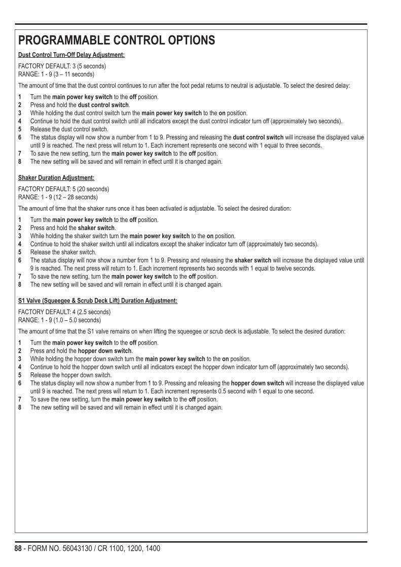
88 - FORM NO. 56043130 / CR 1100, 1200, 1400
PROGRAMMABLE CONTROL OPTIONSDust Control Turn-Off Delay Adjustment:FACTORY DEFAULT: 3 (5 seconds)RANGE: 1 - 9 (3 – 11 seconds)The amount of time that the dust control continues to run after the foot pedal returns to neutral is adjustable. To select the desired delay:1 Turn the main power key switch to the off position.2 Press and hold the dust control switch.3 While holding the dust control switch turn the main power key switch to the on position.4 Continue to hold the dust control switch until all indicators except the dust control indicator turn off (approximately two seconds).5 Release the dust control switch.6 The status display will now show a number from 1 to 9. Pressing and releasing the dust control switch will increase the displayed value
until 9 is reached. The next press will return to 1. Each increment represents one second with 1 equal to three seconds.7 To save the new setting, turn the main power key switch to the off position.8 The new setting will be saved and will remain in effect until it is changed again.
Shaker Duration Adjustment:FACTORY DEFAULT: 5 (20 seconds)RANGE: 1 - 9 (12 – 28 seconds)The amount of time that the shaker runs once it has been activated is adjustable. To select the desired duration:1 Turn the main power key switch to the off position.2 Press and hold the shaker switch.3 While holding the shaker switch turn the main power key switch to the on position.4 Continue to hold the shaker switch until all indicators except the shaker indicator turn off (approximately two seconds).5 Release the shaker switch.6 The status display will now show a number from 1 to 9. Pressing and releasing the shaker switch will increase the displayed value until
9 is reached. The next press will return to 1. Each increment represents two seconds with 1 equal to twelve seconds.7 To save the new setting, turn the main power key switch to the off position.8 The new setting will be saved and will remain in effect until it is changed again.
S1 Valve (Squeegee & Scrub Deck Lift) Duration Adjustment:FACTORY DEFAULT: 4 (2.5 seconds)RANGE: 1 - 9 (1.0 – 5.0 seconds)The amount of time that the S1 valve remains on when lifting the squeegee or scrub deck is adjustable. To select the desired duration:1 Turn the main power key switch to the off position.2 Press and hold the hopper down switch.3 While holding the hopper down switch turn the main power key switch to the on position.4 Continue to hold the hopper down switch until all indicators except the hopper down indicator turn off (approximately two seconds).5 Release the hopper down switch.6 The status display will now show a number from 1 to 9. Pressing and releasing the hopper down switch will increase the displayed value
until 9 is reached. The next press will return to 1. Each increment represents 0.5 second with 1 equal to one second.7 To save the new setting, turn the main power key switch to the off position.8 The new setting will be saved and will remain in effect until it is changed again.

FORM NO. 56043130 / CR 1100, 1200, 1400 - 89
PROGRAMMABLE CONTROL OPTIONSHopper Door Open/Close Duration Adjustment:FACTORY DEFAULT: 3 (2.5 seconds)RANGE: 1 - 9 (2.0 – 4.0 seconds)The amount of time that the valves that open or close the hopper door remain on when automatically opening or closing the door is adjustable. To select the desired duration:1 Turn the main power key switch to the off position.2 Press and hold the hopper door open switch.3 While holding the hopper door open switch turn the main power key switch to the on position.4 Continue to hold the hopper door open switch until all indicators except the hopper door open indicator turn off (approximately two
seconds).5 Release the hopper door open switch.6 The status display will now show a number from 1 to 9. Pressing and releasing the hopper door open switch will increase the displayed
value until 9 is reached. The next press will return to 1. Each increment represents 0.25 second with 1 equal to two seconds.7 To save the new setting, turn the main power key switch to the off position.8 The new setting will be saved and will remain in effect until it is changed again.
Hopper Door, Squeegee & Scrub Deck Lift Position-Refresh Interval Adjustment:FACTORY DEFAULT: 0 (refresh disabled)RANGE: 0 - 9 (5 - 45 minutes)The hydraulic cylinders that control the hopper door, squeegee lift and scrub deck lift are not continuously pressurized by the hydraulic system. If any leakage occurs in the valves that control these cylinders, the cylinder position may drift over time. If this does occur, the control can be programmed to automatically “refresh” the pressure on the cylinders to make sure that they remain at the limit of their travel. This refresh interval is adjustable. To select the desired interval:1 Turn the main power key switch to the off position.2 Press and hold the hopper door close switch.3 While holding the hopper door close switch turn the main power key switch to the on position.4 Continue to hold the hopper door close switch until all indicators except the hopper door close indicator turn off (approximately two
seconds).5 Release the hopper door close switch.6 The status display will now show a number from 1 to 9. Pressing and releasing the hopper door close switch will increase the displayed
value until 9 is reached. The next press will return to 0. Each increment represents five minutes with 1 equal to five minutes. Selecting 0 disables the refresh action.
7 To save the new setting, turn the main power key switch to the off position.8 The new setting will be saved and will remain in effect until it is changed again.
Scrub Pressure Default Adjustment:FACTORY DEFAULT: 1 (minimum pressure)RANGE: 0 - 3The default scrub pressure that is selected each time the scrub system is activated can be adjusted. To select the desired default value: 1 Turn the main power key switch to the off position.2 Press and hold the scrub pressure decrease switch.3 While holding the pressure decrease switch turn the main power key switch to the on position.4 Continue to hold the pressure decrease switch until all indicators except the scrub pressure decrease indicator turn off (approximately two
seconds).5 The status display will now show a number from 0 to 3. Pressing and releasing the scrub pressure decrease switch will increase the
displayed value until 3 is reached. The next press will return to 0. If 0 is selected, the scrub pressure will return to the last used setting when the scrub system is activated. If 1 is selected, the scrub pressure will default to the minimum setting when activated. If 2 is selected, the scrub pressure will default to the medium setting when activated. If 3 is selected, the scrub pressure will default to the maximum setting when activated.
6 To save the new setting, turn the main power key switch to the off position.7 The new setting will be saved and will remain in effect until it is changed again.

90 - FORM NO. 56043130 / CR 1100, 1200, 1400
PROGRAMMABLE CONTROL OPTIONSScrub Pressure Limit Adjustment:FACTORY DEFAULT: 3 (maximum pressure)RANGE: 1 - 3The maximum scrub pressure that the operator can select can be adjusted. To select the desired limit value: 1 Turn the main power key switch to the off position.2 Press and hold the scrub pressure increase switch.3 While holding the pressure increase switch turn the main power key switch to the on position.4 Continue to hold the pressure increase switch until all indicators except the scrub pressure increase indicator turn off (approximately two
seconds).5 The status display will now show a number from 1 to 3. Pressing and releasing the scrub pressure increase switch will increase the
displayed value until 3 is reached. The next press will return to 1. If 1 is selected, the only available scrub pressure will be the minimum setting. If 2 is selected, the minimum and medium scrub pressures will be available. If 3 is selected, all scrub pressures will be available.
6 To save the new setting, turn the main power key switch to the off position.7 The new setting will be saved and will remain in effect until it is changed again.
Foot Pedal Neutral Position and Dead-band Adjustment:FACTORY DEFAULT: 2 RANGE: 1 - 9The various scrub and sweep functions on the CR 1100-1400 are activated when the foot pedal is moved from the neutral position. The engine neutral-start relay is also activated when the foot pedal is moved from the neutral position. These functions are triggered via a position sensor mounted on the hydrostat. Whenever adjustments are made to the hydrostat unit, the neutral position will need to be programmed. Also, the neutral dead-band (sensitivity) can be adjusted if necessary. To set the neutral position and adjust the neutral dead-band perform the following steps:1 Turn the main power key switch to the off position.2 Depress the foot pedal to the full reverse position.3 Allow the foot pedal to slowly return to the neutral position and do not move the pedal during the remainder of this procedure.4 Press and hold the engine speed switch.5 While holding the engine speed switch turn the main power key switch to the on position.6 Continue to hold the engine speed switch until all indicators except the engine speed indicator turn off (approximately two seconds).7 Release the engine speed switch.8 The status display will now show a number from 1 to 9. Pressing and releasing the engine speed switch will increase the displayed value
until 9 is reached. The next press will return to 1. This number represents the dead-band value. A value of 1 results in the smallest dead-band (most sensitive to pedal movement) and 9 results in the largest dead-band (least sensitive to pedal movement). The neutral position is automatically detected at the beginning of this procedure. A dead-band value of 2 or 3 usually produces the best results.
9 To save the new setting, turn the main power key switch to the off position.10 The new setting will be saved and will remain in effect until it is changed again.

FORM NO. 56043130 / CR 1100, 1200, 1400 - 91
PROGRAMMABLE CONTROL OPTIONSBack-up Alarm Mode Control:FACTORY DEFAULT: 1 (reverse only)RANGE: 0 - 4The CR 1100-1400 may be equipped with an optional back-up alarm. This alarm can be programmed to operate at times other than backing up or it may be turned off. To select the operating mode:1 Turn the main power key switch to the off position.2 Press and hold the horn switch.3 While holding the horn switch turn the main power key switch to the on position.4 Continue to hold the horn switch until all indicators except the horn indicator turn off (approximately two seconds).5 Release the horn switch.6 The status display will now show a number from 0 to 4. Pressing and releasing the horn switch will increase the displayed value until 4 is
reached. The next press will return to 0. If 0 is selected, the back-up alarm will be disabled and will not sound at any time. If 1 is selected, the alarm will sound only when backing up. If 2 is selected, the alarm will sound when driving forward or in reverse. It will be off in neutral. If 3 is selected, The alarm will sound when backing up or if the hopper is being raised or lowered. If 4 is selected, The alarm will sound when driving forward or in reverse or if the hopper is being raised or lowered.
7 To save the new setting, turn the main power key switch to the off position.8 The new setting will be saved and will remain in effect until it is changed again.
Side Broom Mode Control:FACTORY DEFAULT: 1 (always turns on with main broom)RANGE: 0 - 2The side brooms on the CR 1100-1400 are programmed to always come on when the main broom is first activated. If this is not desired, the operating mode of the side booms can be changed. To select the operating mode:1 Turn the main power key switch to the off position.2 Press and hold the side broom up/off and the scrub system off switches.3 While holding both switches turn the main power key switch to the on position.4 Continue to hold both switches until all indicators except the side broom up/off and scrub off indicators turn off (approximately two
seconds).5 Release both switches.6 The status display will now show a number from 0 to 2. Pressing and releasing the side broom up/off switch will increase the displayed
value until 2 is reached. The next press will return to 0. If 0 is selected, the side brooms will not come on with the main broom. They will be manual control only. If 1 is selected, the side brooms will always come on when the main broom is initially turned on. If 2 is selected, the side brooms will come on if they were used the last time the main broom was on otherwise they will not automatically come on.
7 To save the new setting, turn the main power key switch to the off position.8 The new setting will be saved and will remain in effect until it is changed again.
Dust Control Mode Control:FACTORY DEFAULT: 1 (always turns on with main broom)RANGE: 0 - 2

92 - FORM NO. 56043130 / CR 1100, 1200, 1400
PROGRAMMABLE CONTROL OPTIONSThe dust control on the CR 1100-1400 is programmed to always come on when the main broom is first activated. If this is not desired, the operating mode of the dust control can be changed. To select the operating mode:1 Turn the main power key switch to the off position.2 Press and hold the dust control and the scrub system off switches.3 While holding both switches turn the main power key switch to the on position.4 Continue to hold both switches until all indicators except the dust control and scrub off indicators turn off (approximately two seconds).5 Release both switches.6 The status display will now show a number from 0 to 2. Pressing and releasing the dust control switch will increase the displayed value
until 2 is reached. The next press will return to 0. If 0 is selected, the dust control will not come on with the main broom. It will be manual control only. If 1 is selected, the dust control will always come on when the main broom is initially turned on. If 2 is selected, the dust control will come on if it was used the last time the main broom was on otherwise it will not automatically come on.
7 To save the new setting, turn the main power key switch to the off position.8 The new setting will be saved and will remain in effect until it is changed again.

FORM NO. 56043130 / CR 1100, 1200, 1400 - 93
PROGRAMMABLE CONTROL OPTIONSShaker Mode Control:FACTORY DEFAULT: 1 (timed – manual control)RANGE: 0 - 3The dust control filter shaker on the CR 1100-1400 is programmed to run for an adjustable period of time when the operator depresses the shaker switch on the control panel. The shaker can be programmed to operate in a momentary fashion or automatically. To select the operating mode:1 Turn the main power key switch to the off position.2 Press and hold the shaker and scrub system off switches.3 While holding both switches turn the main power key switch to the on position.4 Continue to hold both switches until all indicators except the shaker and scrub off indicators turn off (approximately two seconds).5 Release both switches.6 The status display will now show a number from 0 to 3. Pressing and releasing the shaker switch will increase the displayed value until 3
is reached. The next press will return to 0. If 0 is selected, the shaker will turn on only when the control panel switch is held (momentary). If 1 is selected, the shaker will run for an adjustable period of time (see above to adjust time period). If 2 is selected, the shaker will automatically run for an adjustable period of time when the main broom is turned off. If 3 is selected, the shaker will automatically run for an adjustable period of time when the hopper is lowered all the way down after being in the up position.
7 To save the new setting, turn the main power key switch to the off position.8 The new setting will be saved and will remain in effect until it is changed again.
Dust Control Mode Control with Hopper Up:FACTORY DEFAULT: 2 (no change)RANGE: 0 - 2The dust control on the CR 1100-1400 can be programmed to turn on or off or stay in its current state when the hopper is raised for dumping. To select the operating mode:1 Turn the main power key switch to the off position.2 Press and hold the dust control and the scrub pressure decrease switches.3 While holding both switches turn the main power key switch to the on position.4 Continue to hold both switches until all indicators except the dust control and scrub pressure decrease indicators turn off (approximately
two seconds).5 Release both switches.6 The status display will now show a number from 0 to 2. Pressing and releasing the dust control switch will increase the displayed value
until 2 is reached. The next press will return to 0. If 0 is selected, the dust control will turn off when the hopper is raised. If 1 is selected, the dust control will turn on when the hopper is raised. If 2 is selected, the dust control will remain in the same state that it was in prior to raising the hopper (no change).
7 To save the new setting, turn the main power key switch to the off position.8 The new setting will be saved and will remain in effect until it is changed again.
Control Assembly Revision Display:To display the revision of the control assembly, perform the following steps:1 Turn the main power key switch to the off position.2 Press and hold the hopper up switch.3 While holding the hopper up switch turn the main power key switch to the on position.4 Continue to hold the hopper up switch until all indicators except the hopper up indicator turn off (approximately two seconds).5 Release the hopper up switch.6 The status display will now show a letter representing the revision of the display assembly.7 To exit this mode, turn the main power key switch to the off position.

94 - FORM NO. 56043130 / CR 1100, 1200, 1400
PROGRAMMABLE CONTROL OPTIONSSolution Flow in Reverse Enable/Disable:FACTORY DEFAULT: 0 (solution flow off in reverse)RANGE: 0 - 1The solution flow is programmed to stop when backing up to prevent excessive cleaning solution from being dispensed. If it is desired to allow solution flow in reverse, perform the following steps:1 Turn the main power key switch to the off position.2 Press and hold the solution and the scrub system off switches.3 While holding both switches turn the main power key switch to the on position.4 Continue to hold both switches until all indicators except the solution and scrub off indicators turn off (approximately two seconds).5 Release both switches.6 The status display will now show a 0 or a 1. Pressing and releasing the solution switch will alternate between the two. If 0 is selected,
solution flow will stop when backing up. If 1 is selected, solution flow will stay on when backing up. 7 To save the new setting, turn the main power key switch to the off position.8 The new setting will be saved and will remain in effect until it is changed again.
Automatic Engine Speed Control Enable/Disable:FACTORY DEFAULT: 0 (automatic engine speed control disabled)RANGE: 0 - 1The CR 1100-1400 can be programmed to automatically speed-up or slow-down the engine speed based on selected functions. If the automatic engine speed control is enabled, the engine speed will switch to the run speed if any of the major systems are turned on and the foot pedal is moved form the neutral position. The engine speed will return to idle approximately 25 seconds after the foot pedal returns to the neutral position. To turn the automatic control on or off, perform the following steps:1 Turn the main power key switch to the off position.2 Press and hold the engine speed and the scrub system off switches.3 While holding both switches turn the main power key switch to the on position.4 Continue to hold both switches until all indicators except the engine speed and scrub off indicators turn off (approximately two seconds).5 Release both switches.6 The status display will now show a 0 or a 1. Pressing and releasing the engine speed switch will alternate between the two. If 0 is
selected, the automatic engine speed control is disabled (turned off). If 1 is selected, the automatic engine speed control is enabled (turned on).
7 To save the new setting, turn the main power key switch to the off position.8 The new setting will be saved and will remain in effect until it is changed again.
Recall Of Stored Error Codes:Whenever an electrical system fault is detected by the main control unit, one or more error codes are displayed and stored by the control unit. If it is desired, the error code (if any) from the previous operation of the machine can be recalled for troubleshooting purposes. To recall the last stored error codes perform the following steps:1 Turn the main power key switch to the off position.2 Press and hold the solution switch.3 While holding the solution switch, turn the main power key switch to the on position.4 Continue to hold the solution switch until all indicators except the solution indicator turn off (approximately two seconds).5 Release the solution switch.6 If there were previously no error codes stored, the display will now show “-”. Go to step 10.7 If error codes were stored, the display will now show the stored code(s). An example of how two codes, 6 and 18, would be displayed is
as follows:• The display will show “E” followed by a brief blank period• The display will show “0” followed by a brief blank period• The display will show “6” followed by a slightly longer blank period• The display will show “E” followed by a brief blank period• The display will show “1” followed by a brief blank period• The display will show “8” followed by a long blank period• The above sequence will repeat
8 To clear the stored codes press and release the solution switch. The display will now show “-“. Go to step 10.9 If it is desired to save the codes, go to step 10.10 To exit the error code recall mode, turn the main power key switch to the off position.

FORM NO. 56043130 / CR 1100, 1200, 1400 - 95
PROGRAMMABLE CONTROL OPTIONSControl System Self-Diagnostic Mode:If problems with the electronic control system are suspected, this self-diagnostic mode may help isolate the problem. When this mode is activated, the control unit will activate each one of the outputs in sequence and test for short circuits, open circuits, or overload conditions. This mode will also provide an easy test for the touch panel switches and indicators.If an abnormal condition is encountered with one of the outputs, an error code will be displayed. A listing of error codes is provided at the end of this section. 1 During this test, the horn will sound briefly and the scrub deck and squeegee will move if they are in the up position. If the hopper is not in
the down position it will also move slightly. Make sure that all persons are away from these parts of the machine to prevent injury.2 Turn the main power key switch to the off position.3 Press and hold the side broom down/on switch.4 While holding the side broom down/on switch, turn the main power key switch to the on position.5 Continue to hold the side broom down/on switch until all indicators except the side broom down/on indicator turn off (approximately two
seconds).6 Release the side broom down/on switch.7 The control will now activate each output in sequence and perform the tests mentioned above.8 If no abnormal conditions are detected, the display will now show “-”. Go to step 10.9 If abnormal output conditions were detected, the display will now show the error code(s). An example of how two codes, 6 and 18, would
be displayed is as follows:• The display will show “E” followed by a brief blank period• The display will show “0” followed by a brief blank period• The display will show “6” followed by a slightly longer blank period• The display will show “E” followed by a brief blank period• The display will show “1” followed by a brief blank period• The display will show “8” followed by a long blank period• The above sequence will repeat
10 To test any of the control panel switches, press the desired switch. The indicator for that switch should illuminate. If not, consult the service manual trouble-shooting section.
11 The hopper limit, main broom, recovery tank full, and solution tank empty switches may also be tested in this mode. The corresponding indicators will indicate the state of each of the inputs.
12 To exit this mode, turn the main power key switch to the off position.NOTE: If the machine is not equipped with an optional back-up alarm, an error code 20 will be indicated.
Reset of All Programmable Parameters to Factory Default Settings:To reset all of the above parameters to the factory defaults, perform the following steps:1 Turn the main power key switch to the off position.2 Press and hold the all three scrub system switches (scrub off, pressure increase, & pressure decrease).3 While holding all three switches turn the main power key switch to the on position.4 Continue to hold all three switches until all indicators turn off and the status display shows “d” (approximately two seconds).5 Release all switches.6 The programmable parameters are now restored to the default values.7 It will now be necessary to reprogram the throttle neutral position. Refer to the proper section above.8 To exit this mode, turn the main power key switch to the off position.

96 - FORM NO. 56043130 / CR 1100, 1200, 1400
I/O T
able
s fo
r cur
rent
Pro
duct
ion
Mac
hine
s w
/563
0528
8 C
ontr
ol B
ox A
ssem
bly
2/26
/200
7B
- = B
atte
ry -
B+
= B
atte
ry +
Des
igna
tion
Pin
IDW
ireID
/Col
orD
escr
iptio
nSi
gnal
Cha
ract
eris
ticN
omin
alVa
lue
Ref
eren
ceTo
:R
ange
Com
men
ts
Con
trol
Box
Ass
embl
yIn
put
J1-1
PIN
KIg
nitio
n in
put
DC
Vol
tage
+14V
B- (
Gro
und)
12-1
2.6V
w/o
eng
ine
runn
ing
13.5
-14.
5V w
/eng
ine
runn
ing
Out
put
J1-2
YE
LLi
ghts
rela
y (K
2)D
C V
olta
ge+1
4VB
- (G
roun
d)12
-12.
6V w
/o e
ngin
e ru
nnin
g13
.5-1
4.5V
w/e
ngin
e ru
nnin
gLi
ghts
on
Out
put
J1-3
GR
N/B
RN
Bac
k-up
ala
rmD
C V
olta
ge-1
4VB
+12
-12.
6V w
/o e
ngin
e ru
nnin
g13
.5-1
4.5V
w/e
ngin
e ru
nnin
gM
ovin
g in
reve
rse
Out
put
J1-4
GR
N/V
IOS
crub
dow
n va
lve
(S15
)D
C V
olta
ge-1
4VB
+13
.5-1
4.5V
w/e
ngin
e ru
nnin
gM
ovin
g fo
rwar
d an
d sc
rubb
ing
at lo
w o
r m
ediu
m p
ress
ure
setti
ngs
Out
put
J1-5
RE
D/G
RA
Hop
per r
aise
val
ve (S
13)
DC
Vol
tage
-14V
B+
13.5
-14.
5V w
/eng
ine
runn
ing
Rai
sing
hop
per
Out
put
J1-6
BR
N/B
LKS
ide
broo
m v
alve
(S10
)D
C V
olta
ge-1
4VB
+13
.5-1
4.5V
w/e
ngin
e ru
nnin
gM
ovin
g fo
rwar
d an
d sw
eepi
ng w
ith s
ide
broo
ms
dow
nO
utpu
tJ1
-7B
LUV
acuu
m fa
n va
lve
(S8)
DC
Vol
tage
-14V
B+
13.5
-14.
5V w
/eng
ine
runn
ing
Mov
ing
forw
ard
and
sque
egee
dow
nO
utpu
tJ1
-8O
RN
/BLU
Scr
ub v
alve
(S8)
DC
Vol
tage
-14V
B+
13.5
-14.
5V w
/eng
ine
runn
ing
Mov
ing
forw
ard
and
scru
bbin
gO
utpu
tJ1
-9W
HT/
VIO
Scr
ub d
own
valv
e (S
5)D
C V
olta
ge-1
4VB
+13
.5-1
4.5V
w/e
ngin
e ru
nnin
gM
ovin
g fo
rwar
d an
d sc
rubb
ing
at m
ediu
m o
r hi
gh p
ress
ure
setti
ngs
Out
put
J1-1
0B
RN
Dem
and
valv
e (S
3)D
C V
olta
ge-1
4VB
+13
.5-1
4.5V
w/e
ngin
e ru
nnin
gM
ovin
g fo
rwar
d an
d sc
rubb
ing
and
sque
egee
rais
ing
and/
or s
quee
gee
low
erin
gO
utpu
tJ1
-11
BLU
/WH
TD
eman
d va
lve
(S1)
DC
Vol
tage
-14V
B+
13.5
-14.
5V w
/eng
ine
runn
ing
Mov
ing
forw
ard
and
scru
b ra
isin
g an
d/or
sq
ueeg
ee ra
isin
g an
d/or
squ
eege
e lo
wer
ing
Out
put
J1-1
2G
RA
/VIO
Sid
e br
oom
act
uato
r (M
4)
com
mon
DC
Vol
tage
14V
See
com
men
ts13
.5-1
4.5V
w/e
ngin
e ru
nnin
gM
easu
re b
etw
een
J1-2
3 an
d J1
-12
whe
n ra
isin
g si
de b
room
sM
easu
re b
etw
een
J1-3
5 an
d J1
-12
whe
n lo
wer
ing
side
bro
oms
Out
put
J1-1
3G
RA
/WH
TN
eutra
l rel
ay (K
4)D
C V
olta
ge+1
4VB
- (G
roun
d)12
-12.
6V w
/o e
ngin
e ru
nnin
g13
.5-1
4.5V
w/e
ngin
e ru
nnin
gW
hen
driv
e pe
dal i
s pu
shed
forw
ard
or
reve
rse
Out
put
J1-1
4V
IO/B
RN
Hor
n re
lay
(K1)
DC
Vol
tage
+14V
B- (
Gro
und)
12-1
2.6V
w/o
eng
ine
runn
ing
13.5
-14.
5V w
/eng
ine
runn
ing
Sou
ndin
g ho
rn
Out
put
J1-1
5Y
EL/
GR
NS
olut
ion
valv
e (L
16)
DC
Vol
tage
-14V
B+
13.5
-14.
5V w
/eng
ine
runn
ing
Mov
ing
forw
ard
and
scru
bbin
gO
utpu
tJ1
-16
YE
L/R
ED
Hop
per l
ower
val
ve (S
14)
DC
Vol
tage
-14V
B+
13.5
-14.
5V w
/eng
ine
runn
ing
Low
erin
g ho
pper
Out
put
J1-1
7B
RN
/GR
ND
ump
door
clo
se v
alve
D
C V
olta
ge-1
4VB
+13
.5-1
4.5V
w/e
ngin
e ru
nnin
gC
losi
ng d
ump
door
Out
put
J1-1
8B
RN
/YE
LD
ust c
ontro
l val
ve (S
9)D
C V
olta
ge-1
4VB
+13
.5-1
4.5V
w/e
ngin
e ru
nnin
gD
ust c
ontro
l on
Out
put
J1-1
9B
LK/W
HT
Dum
p do
or o
pen
valv
e (S
11)
DC
Vol
tage
-14V
B+
13.5
-14.
5V w
/eng
ine
runn
ing
Ope
ning
dum
p do
orO
utpu
tJ1
-20
GR
N/G
RA
Mai
n br
oom
val
ve (S
6)D
C V
olta
ge-1
4VB
+13
.5-1
4.5V
w/e
ngin
e ru
nnin
gM
ovin
g fo
rwar
d an
d sw
eepi
ngO
utpu
tJ1
-21
YE
L/B
LUS
crub
dow
n va
lve
(S4)
DC
Vol
tage
-14V
B+
13.5
-14.
5V w
/eng
ine
runn
ing
Mov
ing
forw
ard
and
scru
bbin
g at
low
or h
igh
pres
sure
set
tings
Out
put
J1-2
2O
RN
/RE
DS
quee
gee
Val
ve (S
2)D
C V
olta
ge-1
4VB
+13
.5-1
4.5V
w/e
ngin
e ru
nnin
gM
ovin
g fo
rwar
d an
d sq
ueeg
ee d
own
Out
put
J1-2
3G
RN
/YE
LS
ide
broo
m a
ctua
tor (
M4)
ra
ise
DC
Vol
tage
-14V
B+
13.5
-14.
5V w
/eng
ine
runn
ing
Mea
sure
bet
wee
n J1
-23
and
J1-1
2 w
hen
rais
ing
side
bro
oms

FORM NO. 56043130 / CR 1100, 1200, 1400 - 97
Des
igna
tion
Pin
IDW
ireID
/Col
orD
escr
iptio
nSi
gnal
Cha
ract
eris
ticN
omin
alVa
lue
Ref
eren
ceTo
:R
ange
Com
men
ts
Con
trol
Box
Ass
embl
yO
utpu
tJ1
-24
GR
NS
hake
r rel
ay (K
3)D
C V
olta
ge-1
4VB
+12
-12.
6V w
/o e
ngin
e ru
nnin
g13
.5-1
4.5V
w/e
ngin
e ru
nnin
gS
hake
r on
J1-2
5E
mpt
yO
utpu
tJ1
-26
GR
A/B
LUTh
rottl
e ou
tput
DC
Vol
tage
+14V
B- (
Gro
und)
13.5
-14.
5V w
/eng
ine
runn
ing
On
whe
n hi
gh e
ngin
e sp
eed
is s
elec
ted
J1-2
7E
mpt
yJ1
-28
Em
pty
Inpu
tJ1
-29
BLK
B-
DC
Vol
tage
-14V
B+
12-1
2.6V
w/o
eng
ine
runn
ing
13.5
-14.
5V w
/eng
ine
runn
ing
Inpu
tJ1
-30
BLK
B-
DC
Vol
tage
-14V
B+
12-1
2.6V
w/o
eng
ine
runn
ing
13.5
-14.
5V w
/eng
ine
runn
ing
Inpu
tJ1
-31
BLK
B-
DC
Vol
tage
-14V
B+
12-1
2.6V
w/o
eng
ine
runn
ing
13.5
-14.
5V w
/eng
ine
runn
ing
Inpu
tJ1
-32
BLK
B-
DC
Vol
tage
-14V
B+
12-1
2.6V
w/o
eng
ine
runn
ing
13.5
-14.
5V w
/eng
ine
runn
ing
Inpu
tJ1
-33
BLK
B-
DC
Vol
tage
-14V
B+
12-1
2.6V
w/o
eng
ine
runn
ing
13.5
-14.
5V w
/eng
ine
runn
ing
Inpu
tJ1
-34
VIO
Acc
esso
ry p
ower
DC
Vol
tage
+14V
B- (
Gro
und)
12-1
2.6V
w/o
eng
ine
runn
ing
13.5
-14.
5V w
/eng
ine
runn
ing
Out
put
J1-3
5B
LU/B
RN
Sid
e br
oom
act
uato
r (M
4)
low
erD
C V
olta
ge+1
4VB
- (G
roun
d)13
.5-1
4.5V
w/e
ngin
e ru
nnin
gM
easu
re b
etw
een
J1-3
5 an
d J1
-12
whe
n lo
wer
ing
side
bro
oms
J2-1
Em
pty
Out
put
J2-2
YE
L/G
RA
Driv
e pe
dal s
enso
r (R
2) lo
w
side
DC
Vol
tage
-5V
J2-1
7
Inpu
tJ2
-3G
RA
Low
LP
G p
ress
ure
switc
h (S
3)D
C V
olta
ge-1
2VB
+12
-12.
6V w
/o e
ngin
e ru
nnin
gO
n w
hen
LPG
tank
is e
mpt
y or
fuel
line
is
disc
onne
cted
Inpu
tJ2
-4Y
EL/
VIO
Hop
per f
ire s
witc
h (S
7)
DC
Vol
tage
-14V
B+
13.5
-14.
5V w
/eng
ine
runn
ing
On
whe
n in
tern
al te
mpe
ratu
re o
f hop
per i
s to
o hi
ghIn
put
J2-5
YE
L/W
HT
Hyd
raul
ic fi
lter s
witc
h (S
6)D
C V
olta
ge-1
4VB
+13
.5-1
4.5V
w/e
ngin
e ru
nnin
gO
n w
hen
filte
r is
too
dirty
or p
lugg
edIn
put
J2-6
WH
T/G
RA
Dus
t con
trol f
ilter
sw
itch
(S5)
DC
Vol
tage
-14V
B+
13.5
-14.
5V w
/eng
ine
runn
ing
On
whe
n ho
pper
filte
r is
too
dirty
or p
lugg
edIn
put
J2-7
VIO
/YE
LS
olut
ion
empt
y sw
itch
(S9)
DC
Vol
tage
-14V
B+
12-1
2.6V
w/o
eng
ine
runn
ing
13.5
-14.
5V w
/eng
ine
runn
ing
On
whe
n so
lutio
n ta
nk is
em
pty
Inpu
tJ2
-8G
RA
/YE
LR
ecov
ery
full
switc
h (S
8)D
C V
olta
ge-1
4VB
+12
-12.
6V w
/o e
ngin
e ru
nnin
g13
.5-1
4.5V
w/e
ngin
e ru
nnin
gO
ff w
hen
reco
very
tank
is fu
ll or
di
scon
nect
edJ2
-9E
mpt
yIn
put
J2-1
0O
RN
/GR
AD
rive
peda
l sen
sor (
R2)
w
iper
DC
Vol
tage
0 to
+5V
J2-2
0-5V
Inpu
t/Out
put
J2-1
1B
RN
/BLU
To s
witc
h/di
spla
y pa
nel (
A4)
Ser
ial c
lock
sig
nal0
to +
5VB
- (G
roun
d)0-
5VIn
put/O
utpu
tJ2
-12
GR
N/B
LUTo
sw
itch/
disp
lay
pane
l (A
4)S
eria
l dat
a si
gnal
0 to
+5V
B- (
Gro
und)
0-5V
Inpu
tJ2
-13
BLU
/BLK
Che
ck e
ngin
e lig
htD
C V
olta
ge-1
2VB
+12
-12.
6V w
/o e
ngin
e ru
nnin
gK
ey s
witc
h on
and
eng
ine
not r
unni
ng.
Inpu
tJ2
-14
RE
D/B
LKH
oppe
r int
erlo
ck s
witc
h (S
12)
DC
Vol
tage
-14V
B+
12-1
2.6V
w/o
eng
ine
runn
ing
13.5
-14.
5V w
/eng
ine
runn
ing
On
whe
n ho
pper
is d
own
Inpu
tJ2
-15
OR
N/B
LKM
ain
broo
m s
witc
h (S
16)
DC
Vol
tage
-14V
B+
12-1
2.6V
w/o
eng
ine
runn
ing
13.5
-14.
5V w
/eng
ine
runn
ing
Off
whe
n m
ain
broo
m is
dow
n
Inpu
tJ2
-16
BLK
/YE
LW
and
switc
h (S
2)D
C V
olta
ge-1
4VB
+12
-12.
6V w
/o e
ngin
e ru
nnin
g13
.5-1
4.5V
w/e
ngin
e ru
nnin
gO
n w
ith w
and
switc
h

98 - FORM NO. 56043130 / CR 1100, 1200, 1400
Des
igna
tion
Pin
IDW
ireID
/Col
orD
escr
iptio
nSi
gnal
Cha
ract
eris
ticN
omin
alVa
lue
Ref
eren
ceTo
:R
ange
Com
men
ts
Con
trol
Box
Ass
embl
yO
utpu
tJ2
-17
BR
N/W
HT
Driv
e pe
dal s
enso
r (R
2) h
igh
side
DC
Vol
tage
+5V
J2-2
J2-1
8O
RN
/BR
NN
ot u
sed
Inpu
tJ2
-19
RE
D/Y
EL
Ligh
t sen
sor
DC
Vol
tage
Bet
wee
n0
and
+5V
B- (
Gro
und)
0-5V
Out
put
J2-2
0B
LKTo
sw
itch/
disp
lay
pane
l (A
4)D
C V
olta
ge-1
4VB
+12
-12.
6V w
/o e
ngin
e ru
nnin
g13
.5-1
4.5V
w/e
ngin
e ru
nnin
gO
utpu
tJ2
-21
WH
T/B
RN
To s
witc
h/di
spla
y pa
nel (
A4)
DC
Vol
tage
+14V
B- (
Gro
und)
12-1
2.6V
w/o
eng
ine
runn
ing
13.5
-14.
5V w
/eng
ine
runn
ing
Inpu
tJ2
-22
PIN
KIg
nitio
n in
put
DC
Vol
tage
+14V
B- (
Gro
und)
12-1
2.6V
w/o
eng
ine
runn
ing
13.5
-14.
5V w
/eng
ine
runn
ing
J2-2
3E
mpt
y
Switc
h/D
ispl
ay P
anel
Ass
embl
yJ3
-1E
mpt
yO
utpu
tJ3
-2R
ED
/YE
LLi
ght s
enso
rD
C V
olta
geB
etw
een
0 an
d +5
VB
- (G
roun
d)0-
5V
J3-3
OR
N/B
RN
Not
use
dJ3
-4E
mpt
yIn
put/O
utpu
tJ3
-5B
RN
/BLU
To c
ontro
l box
ass
embl
y S
eria
l clo
ck s
igna
l0 to
+5V
B- (
Gro
und)
0-5V
Inpu
t/Out
put
J3-6
GR
N/B
LUTo
con
trol b
ox a
ssem
bly
Ser
ial d
ata
sign
al0
to +
5VB
- (G
roun
d)0-
5VIn
put
J3-7
WH
T/B
RN
To c
ontro
l box
ass
embl
y (A
1)D
C V
olta
ge+1
4VB
+12
-12.
6V w
/o e
ngin
e ru
nnin
g13
.5-1
4.5V
w/e
ngin
e ru
nnin
gIn
put
J3-8
BLK
To c
ontro
l box
ass
embl
y (A
1)D
C V
olta
ge-1
4VB
- (G
roun
d)12
-12.
6V w
/o e
ngin
e ru
nnin
g13
.5-1
4.5V
w/e
ngin
e ru
nnin
g

FORM NO. 56043130 / CR 1100, 1200, 1400 - 99
AXP/EDS SYSTEMKNOW YOUR MACHINEAXP/EDS detergent system control box assembly and control panel callouts
A Detergent Ratio Magnetic SliderB Detergent Dilution Ratio DecalC Detergent Cartridge CapD Detergent Cartridge Dry Break CapE Detergent BoxF Detergent Level Viewing SlotG AXP/EDS Control Box AssemblyH Dual 12V Detergent PumpsNN AXP/EDS System Supervisor Mode Display IconRR AXP/EDS Detergent ON/OFF SwitchSS Detergent Ratio Increment (increase) SwitchTT Detergent Ratio Decrement (decrease) SwitchUU AXP/EDS System Display PanelVV Main Solution Pump Flow Indicator (bar) Display 40%-100%WW Detergent Ratio Active Status Call Out DisplayXX AXP/EDS System Error Code (E1) Panel DisplayYY AXP/EDS System Operational Status (LED) Indicator LightZZ Detergent Ratio (magnetic slider) Sensor Assembly

100 - FORM NO. 56043130 / CR 1100, 1200, 1400
AXP/EDS SYSTEM
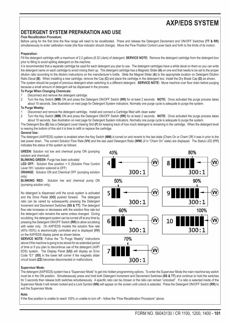
FORM NO. 56043130 / CR 1100, 1200, 1400 - 101
AXP/EDS SYSTEMDETERGENT SYSTEM PREPARATION AND USEFlow Recalibration Procedure:Before using for the first time the flow range will need to be recalibrated. Press and release the Detergent Decrement and ON/OFF Switches (TT & RR) simultaneously to enter calibration mode (the flow indicator should change). Move the Flow Position Control Lever back and forth to the limits of its motion.
Preparation:Fill the detergent cartridge with a maximum of 2.2 gallons (8.32 Liters) of detergent. SERVICE NOTE: Remove the detergent cartridge from the detergent box prior to filling to avoid spilling detergent on the machine.It is recommended that a separate cartridge be used for each detergent you plan to use. The detergent cartridges have a white decal on them so you can write the detergent name on each cartridge to avoid mixing them up. The detergent cartridge has a Magnetic Slider (A) on one end that needs to be set to the proper dilution ratio according to the dilution instructions on the manufacturer’s bottle. Slide the Magnet Slider (A) to the appropriate location on Detergent Dilution Ratio Decal (B). When installing a new cartridge, remove the Cap (C) and place the cartridge in the detergent box. Install the Dry Break Cap (D) as shown.The system should be purged of previous detergent when switching to a different detergent. SERVICE NOTE: Move machine over floor drain before purging because a small amount of detergent will be dispensed in the process.To Purge When Changing Chemicals:1 Disconnect and remove the detergent cartridge.2 Turn the Key Switch (MM) ON and press the Detergent ON/OFF Switch (RR) for at least 2 seconds. NOTE: Once activated the purge process takes
about 10 seconds. See illustration on next page for Detergent System indicators. Normally one purge cycle is adequate to purge the system.To Purge Weekly:1 Disconnect and remove the detergent cartridge. Install and connect a Cartridge filled with clean water2 Turn the Key Switch (MM) ON and press the Detergent ON/OFF Switch (RR) for at least 2 seconds. NOTE: Once activated the purge process takes
about 10 seconds. See illustration on next page for Detergent System indicators. Normally one purge cycle is adequate to purge the system.The Detergent Box (E) has a Detergent Level Viewing Slot (F) for keeping track of how much detergent is remaining in the cartridge. When the detergent level is nearing the bottom of this slot it is time to refill or replace the cartridge.General Use:The detergent (AXP/EDS) system is enabled when the Key Switch (MM) is turned on and reverts to the last state (Chem On or Chem Off) it was in prior to the last power down. The current Solution Flow Rate (VV) and the last used Detergent Ratio (WW) (if in “Chem On” state) are displayed. The Status LED (YY) indicates the status of the system as follows:
GREEN: Solution not low and chemical pump ON (pumping solution and chemical)BLINKING GREEN: Purge has been activatedLED OFF: Solution flow position = 0 (Solution Flow Control Lever HH / solution solenoid is OFF)ORANGE: Solution ON and Chemical OFF (pumping solution only)BLINKING RED: Solution low and chemical pump ON (pumping solution only) No detergent is dispensed until the scrub system is activated and the Drive Pedal (OO) pushed forward. The detergent ratio can be varied by subsequently pressing the Detergent Increment and Decrement Switches (SS & TT). The detergent flow rate increases or decreases with the solution flow rate but the detergent ratio remains the same unless changed. During scrubbing, the detergent system can be turned off at any time by pressing the Detergent ON/OFF Switch (RR) to allow scrubbing with water only. On AXP/EDS models the solution flow rate (40%-100%) is electronically controlled and is displayed (VV) on the AXP/EDS display panel as shown below.SERVICE NOTE: Follow the “To Purge Weekly” instructions above if the machine is going to be stored for an extended period of time or if you plan to discontinue use of the detergent (AXP/EDS) system. The Display Panel (UU) will display an Error Code “E1” (XX) in the lower left corner if the magnetic slider circuit board (ZZ) becomes disconnected or malfunctions.
Supervisor Mode:The detergent (AXP/EDS) system has a “Supervisor Mode” to get into hidden programming options. To enter the Supervisor Mode the main machine key switch must be in the ON position. Simultaneously press and hold both Detergent Increment and Decrement Switches (SS & TT) and continue to hold the switches for 3 seconds then release both switches simultaneously. A specific ratio can be chosen or the ratio can remain “unlocked”. If a ratio is selected inside of the Supervisor Mode it will remain locked and a Lock Symbol (NN) will appear on the screen until unlock is selected. Press the Detergent ON/OFF Switch (RR) to exit the Supervisor Mode.Note:If the flow position is unable to reach 100% or unable to turn off – follow the “Flow Recalibration Procedure” above.

102 - FORM NO. 56043130 / CR 1100, 1200, 1400
AXP/EDS SYSTEMKNOW YOUR MACHINE AXP/EDS System (Continued)Main Solution System Components
4 Cable Solution Control Lever13 Solution Filter Elbow Fitting14 Solution Sensor Potentiometer (connected to solution control lever)21 Solution System Pump Assembly25 Detergent Pump Output Delivery Hose27 Solution & Detergent Tee Fitting

FORM NO. 56043130 / CR 1100, 1200, 1400 - 103
AXP/EDS SYSTEMAXP/EDS SYSTEM ELECTRICAL HARNESS AND ROUTING DIAGRAM
GRA/BRN 18-2GRA/BRN 18-1ORN 18-26BLK 18-37
VIO/GRA 18-1
VIO/YEL 18-2
YEL/GRN 18-4
ORN 18-26RED 14-1
RED 14-1VIO/GRA 18-1
BLK 18-37BLK 18-36BLK 18-35
GRA/BRN 18-2BLK 18-35
YEL/GRN 18-4BLU/ORN 18-1
BLK/GRA 18-1VIO/YEL 18-2
GRA/BRN 18-4BLK/GRA 18-1
GRA/BRN 18-3 BLK 18-36BLU/ORN 18-1
X81
X167
X169
R4
F8
F9 X7
K6
SP16
SP17
to SolutionPump
to SolutionControl Pot
to Ground
to AXP Control Box
to CircuitBreakers
to Main HarnessPos (+) to Relay #30
to A1 Control Box
to Relay

104 - FORM NO. 56043130 / CR 1100, 1200, 1400
AXP/EDS SYSTEMAXP/EDS SPECIFICATIONS
• Qty 1 refillable detergent storage cartridge (tank) capacity 2.25 gal (8.5L)• Available dilution rates: 21:1, 26:1, 32:1, 50:1, 64:1, 100:1, 128:1, 150:1, 200:1, 256:1, 300:1
AXP/EDSdisplaypanelsolutionflowratetableFlow % Solution volume
40% 1.20 gal/min (4.54L/min)50% 1.41 gal/min (5.33L/min)60% 1.85 gal/min (7.00L/min)70% 2.09 gal/min (7.91L/min)80% 2.46 gal/min (9.31L/min)90% 2.76 gal/min (10.44L/min)
100% 3.10 gal/min (11.73L/min)