Embed Size (px)
Citation preview
1
CPE 626 Advanced VLSI Design
Lecture 10: FPGA Structures
Aleksandar Milenkovic
http://www.ece.uah.edu/~milenkahttp://www.ece.uah.edu/~milenka/cpe626-04F/
Assistant ProfessorElectrical and Computer Engineering Dept.
University of Alabama in Huntsville
A. Milenkovic 2
Advanced VLSI Design
Outline
Programmable ASICs
IntroductionAntifuse
Static RAMEPROM, EEPROM Technology
A. Milenkovic 3
Advanced VLSI Design
Introduction
Programmable ASICsPLDs – Programmable Logic Devices
• started as small devices (to replace a handful of TTLs)
FPGAs – Field Programmable Gate ArraysFPGA – a chip you can program yourself
an IC foundry produces FPGAs with some connections missingafter design and simulation, special software is used to produce a string of bits describing the extra connections required to make the design –the configuration fileprogram the chip – make the necessary connections according to the configuration file

2
A. Milenkovic 4
Advanced VLSI Design
Introduction (cont’d)
No customization of any mask levelFPGA are manufactured as standard part in high volumes
Ideal for prototyping or for low -volume production
FPGA vendors do not need IC fabrication facility
Contract IC foundries to produce their parts• fabs cost hundreds of millions of dollars
Put their effort in architecture and software • much easier to make a profit by selling design software
A. Milenkovic 5
Advanced VLSI Design
FPGA Characteristics
All have regular array of basic logic cells that are configured using a programming tech.Chip inputs and outputs use special I/O logic cellsA programmable interconnect scheme forms the wiring between the two types of logic cellsDesigners use custom software, tailored for each programming technology and FPGA architecture to design and implement interconnectionsTypes of programming technology
permanent programming (OTP – One Time Programmable)Reprogrammable or erasable
A. Milenkovic 6
Advanced VLSI Design
FPGA Internal StructureTop FPGA vendors in 2002 areXilinx, Inc. and Altera CorporationBasic internal structure
PLB – Programmable Logic Blocks
PI – Programmable Interconnect
Current trends: include RAM and/or a fixed microprocessor core
3
A. Milenkovic 7
Advanced VLSI Design
Antifuse
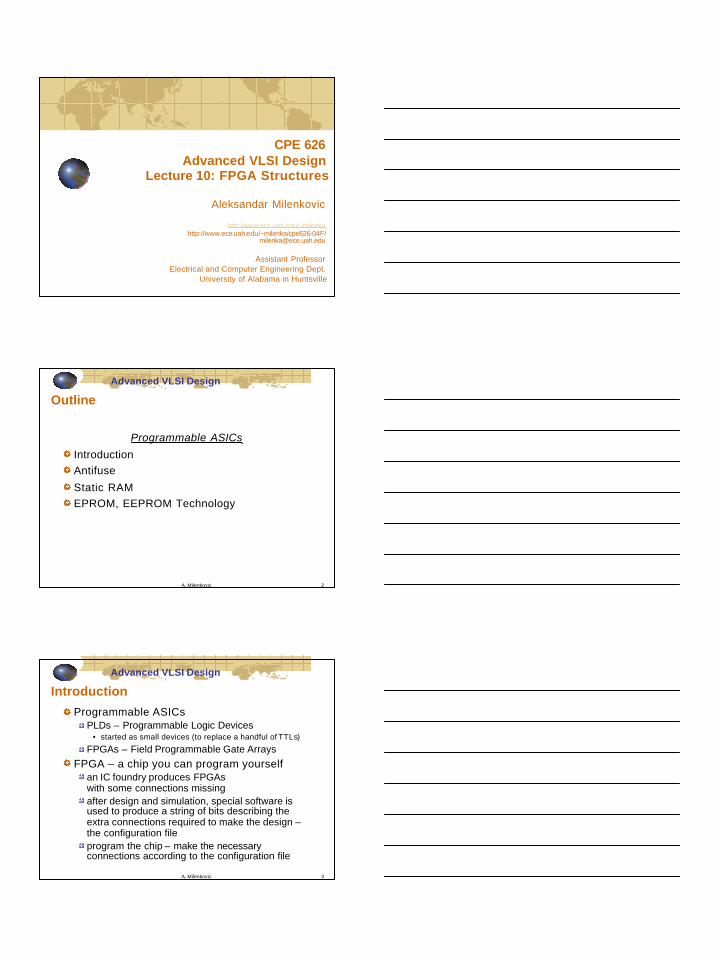
Antifusenormally it is an open circuit until forcing a programming current through itActel calls its antifuse a programmable low-impedance circuit element ( PLICE) OTP technology
A. Milenkovic 8
Advanced VLSI Design
Antifuse (cont’d)
Programming current controls the antifuse resistance (typically for 5mA it is 500 Ohms)
reduce resistance by increasing the current
Design Stepsdesign entry + simulation until the design is correct plug the chip into a socket on a special programming box, called Activator (provides programming voltage)PC downloads the configuration file instruction the Activator which antifuses to blow Remove the chip from the Activator
In-system programming (ISP) – possibility to program the chip after it has been assembled on the PCB
A. Milenkovic 9
Advanced VLSI Design
Antifuse (cont’d)
Actel antifuse technology uses modified CMOS process
double metal, single poly typically includes 12 masksActel process requires an additional 3 masks
Actel A1010 – 112,000 antifuses,Actel A1020 – 186, 000 antifuses, ...Programming time: 5 – 10 minutes
4
A. Milenkovic 10
Advanced VLSI Design
Metal-metal antifuse
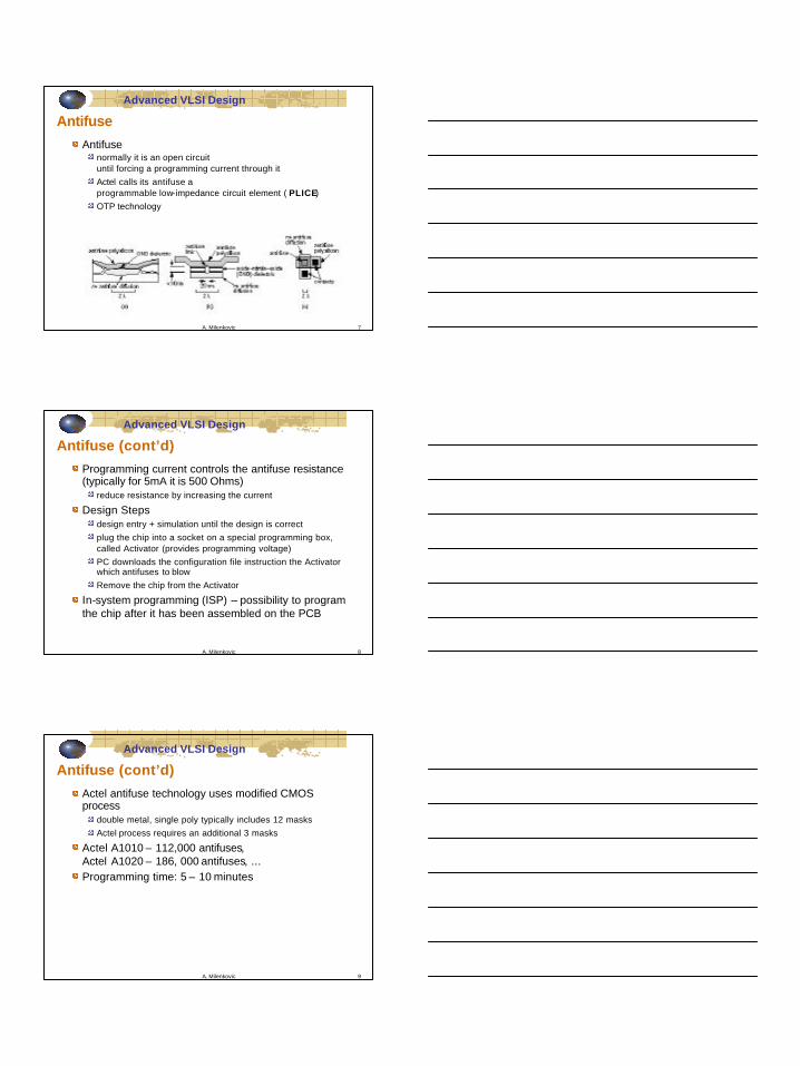
QuickLogic metal-metal antifuseconnections are direct to metal wiring layers
• connections from poly-diffusion antifuse to wiring layers require extra space and create additional parasitics
easier to use larger programming currents to reduce the antifuse resistance
A. Milenkovic 11
Advanced VLSI Design
Static RAM Programming
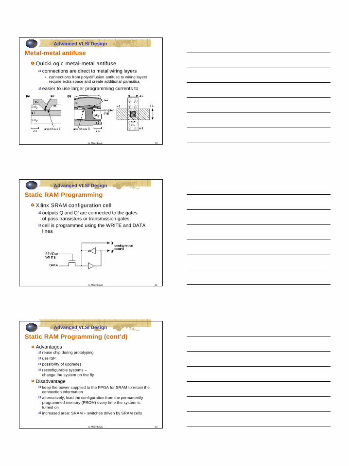
Xilinx SRAM configuration celloutputs Q and Q’ are connected to the gates of pass transistors or transmission gatescell is programmed using the WRITE and DATA lines
A. Milenkovic 12
Advanced VLSI Design
Static RAM Programming (cont’d)
Advantagesreuse chip during prototypinguse ISPpossibility of upgradesreconfigurable systems –change the system on the fly
Disadvantagekeep the power supplied to the FPGA for SRAM to retain the connection informationalternatively, load the configuration from the permanently programmed memory (PROM) every time the system is turned onincreased area: SRAM + switches driven by SRAM cells
5
A. Milenkovic 13
Advanced VLSI Design
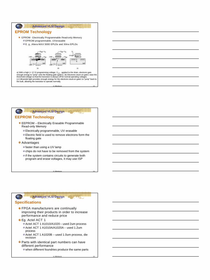
EPROM TechnologyEPROM - Electrically Programmable Read-only Memory
EPROM programmable, UV-erasable E. g., Altera MAX 5000 EPLDs and Xilinx EPLDs
a) With a high (> 12 V) programming voltage, V PP , applied to the drain, electrons gain enough energy to “jump” onto the floating gate (gate1). (b) Electrons stuck on gate1 raise the threshold voltage so that the transistor is always off for normal operating voltages. (c) Ultraviolet light provides enough energy for the electrons stuckon gate1 to “jump” back to the bulk, allowing the transistor to operate normally.
A. Milenkovic 14
Advanced VLSI Design
EEPROM Technology
EEPROM – Electrically Erasable Programmable Read-only Memory
Electrically programmable, UV-erasable Electric field is used to remove electrons form the floating gate
Advantagesfaster than using a UV lampchips do not have to be removed from the systemif the system contains circuits to generate both program and erase voltages, it may use ISP
A. Milenkovic 15
Advanced VLSI Design
Specifications
FPGA manufacturers are continually improving their products in order to increase performance and reduce priceEg. Actel ACT 1
Actel ACT 1 A1010/A1020 – used 2um processActel ACT 1 A1010A/A1020A – used 1.2um processActel ACT 1 A1020B – used 1.0um process, die revision
Parts with identical part numbers can have different performance
when different foundries produce the same parts
6
A. Milenkovic 16
Advanced VLSI Design
PREP BenchmarksProgrammable Electronics Performance Companyhttp://www.prep.org
non-profit organization that developed a series of benchmarks for FPGAs
PREP 1.31. An 8-bit datapathconsisting of 4:1 MUX, register, and shift -register 2. An 8-bit timer–counter consisting of two registers, a 4:1 MUX, a
counter and a comparator 3. A small state machine (8 states, 8 inputs, and 8 outputs) 4. A larger state machine (16 states, 8 inputs, and 8 outputs) 5. An ALU consisting of a 4 ∞ 4 multiplier, an 8-bit adder, and an 8-bit
register 6. A 16-bit accumulator 7. A 16-bit counter with synchronous load and enable 8. A 16-bit prescaledcounter with load and enable 9. A 16-bit address decoder
A. Milenkovic 17
Advanced VLSI Design
FPGA Economics
FPGA vendors offer a wide variety of packing, speed, and qualification (military, industrial, or commercial) options in each family
Xilinx part-naming convention
A. Milenkovic 18
Advanced VLSI Design
FPGA Pricing
Xilinx XC3000 series options from 1992Five different size parts: XC30{20, 30, 42, 64, 90} Three different speed grades or bins: {50, 70, 100} Ten different packages: {PC68, PC84, PG84, PQ100, CQ100, PP132, PG132, CQ184, PP175, PG175} Four application ranges or qualification types: {C, I, M, B}
1992 base Xilinx XC3000 FPGA pricesXC3020- 50PC68C $26.00XC3030- 50PC44C $34.20XC3042- 50PC84C $52.00XC3064- 50PC84C $87.00XC3090- 50PC84C $133.30

7
A. Milenkovic 19
Advanced VLSI Design
Summary
FPGA programming technologies antifuseSRAMEPROM technologies
Key elementsThe programming technology The basic logic cells The I/O logic cells Programmable interconnect Software to design and program the FPGA
A. Milenkovic 20
Advanced VLSI Design
Advanced FPGAs
Xilinx XC9500Xilinx Virtex- II
Altera Stratix
A. Milenkovic 21
Advanced VLSI Design
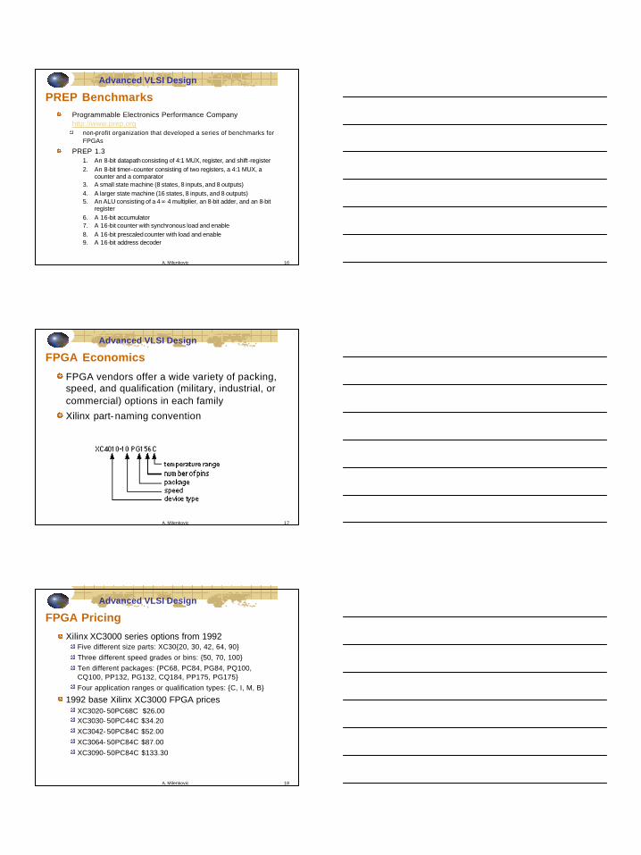
Xilinx XC9500
Selected featuresHigh-performance
• 5 ns pin-to -pin logic delays on all pins
Large density range - 36 to 288 macrocells with 800 to 6,400 usable gates5 V in-system programmableEndurance of 10,000 program/erase cyclesProgram/erase over full commercial voltage and temperature rangeProgrammable power reduction mode in each macrocellHigh-drive 24 mA outputs3.3 V or 5 V I/O capabilityAdvanced CMOS 5V FastFLASH technologySupports parallel programming of multiple XC9500 devices
8
A. Milenkovic 22
Advanced VLSI Design
Xilinx XC9500
A. Milenkovic 23
Advanced VLSI Design
Xilinx XC9500 Function Block
A. Milenkovic 24
Advanced VLSI Design
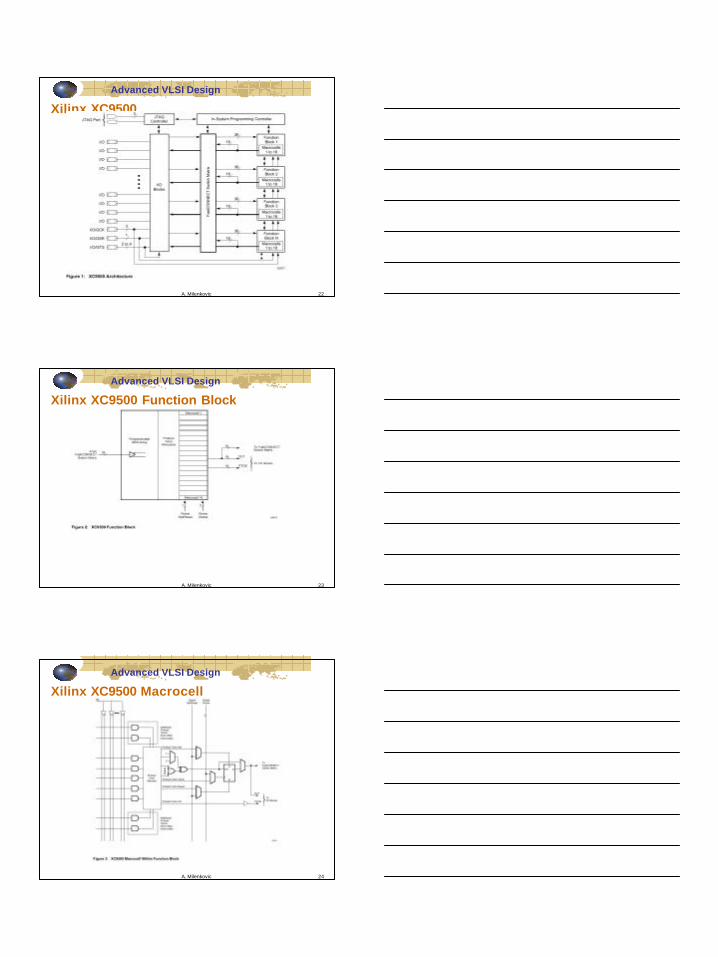
Xilinx XC9500 Macrocell
9
A. Milenkovic 25
Advanced VLSI DesignXilinx XC9500 Macrocell Clock Set/Reset Cap.
A. Milenkovic 26
Advanced VLSI Design
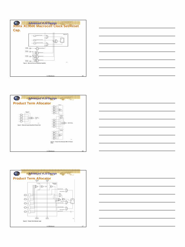
Product Term Allocator
A. Milenkovic 27
Advanced VLSI Design
Product Term Allocator
10
A. Milenkovic 28
Advanced VLSI Design
FastCONNECT Switch Matrix
A. Milenkovic 29
Advanced VLSI Design
IO Block
A. Milenkovic 30
Advanced VLSI Design
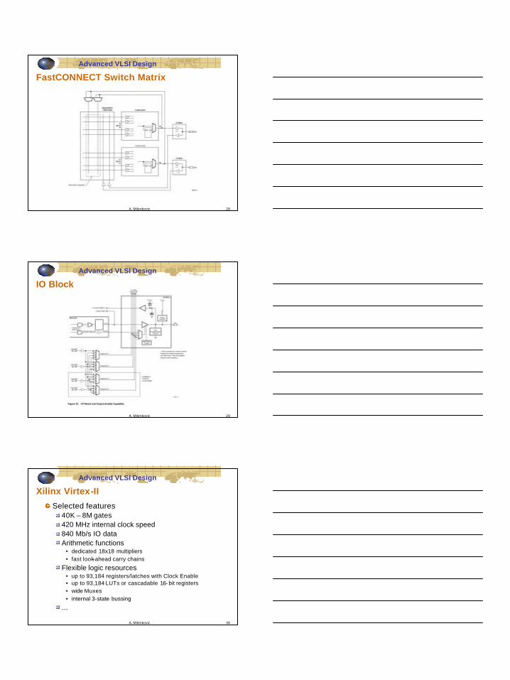
Xilinx Virtex-II
Selected features40K – 8M gates420 MHz internal clock speed840 Mb/s IO dataArithmetic functions
• dedicated 18x18 multipliers• fast look-ahead carry chains
Flexible logic resources• up to 93,184 registers/latches with Clock Enable• up to 93,184 LUTs or cascadable 16- bit registers• wide Muxes• internal 3-state bussing
...

11
A. Milenkovic 31
Advanced VLSI Design
Xilinx Virtex-II (cont’d)Configurable Logic Blocks (CLBs) provide functional elements for combinatorial and synchronous logic, including basic storage elements. BUFTs (3-state buffers) associated with each CLB element drive dedicated segmentable horizontal routing resources.Block SelectRAM memory modules provide large 18-Kbit storage elements of True Dual-Port RAM.Multiplier blocks are 18-bit x 18-bit dedicated multipliers.DCM (Digital Clock Manager) blocks provide self-calibrating, fully digital solutions for clock distribution delay compensation, clock multiplication and division, coarse and fine-grained clock phase shifting.
A. Milenkovic 32
Advanced VLSI Design
Xilinx Virtex-II (cont’d)
A. Milenkovic 33
Advanced VLSI Design
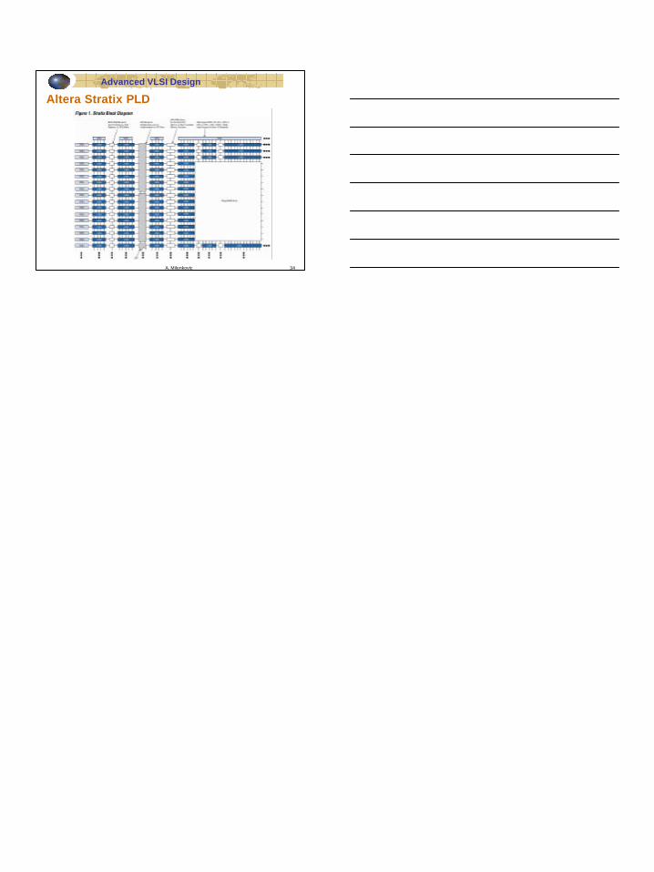
Altera Stratix PLD (cont’d)New high-performance architecture built for block- based design methodologyBased on an industry-leading 1.5-V, 0.13-µm, all-layer-copper processSystem-Level Features
Up to 114,140 logic elements (LEs) Up to 10 Mbits embedded memory and 12 terabits per second memory bandwidth Up to 28 optimized digital signal processing (DSP) blocks Up to 116 high-speed differential I/O channels with up to 80 channels optimized for 840-Mbps operation Up to 12 phase-locked loops (PLLs) supporting 40 different clock domains On-chip termination for differential and single-ended I/O standards that improves signal integrity and simplifies board layout Convenient remote system upgrade capability and configuration error recovery circuitry
12
A. Milenkovic 34
Advanced VLSI Design
Altera Stratix PLD