Embed Size (px)
Citation preview
COVERING OUR RANGE OF DEXTER ELECTRIC BRAKE AXLES AND RELATED
COMPONENTSApril 2016
This manual is designed to provideinformation for the Trailer and
Caravan owner to effectively use,maintain and service the Dexter brand
braking system.
The Dexter unit has beenengineered over the years to
provide the highest efficiency inbraking performance to ensure manyyears of safe and trouble-free towing.
IntroductionImportant Safety Notice 5Set-up and Adjustment 5
Electric BrakesFeatures 6Operation 6Trailer Wiring 7Electric Brake Line Diagram 8 & 9Wiring Recommendations 10Parking Brake Option 11Correct use of your Electric Brakes 11To Synchronise Tow Vehicle & Trailer Braking 13Controllers 14
General MaintenanceBrake Adjustment 15Brake Cleaning and Inspection 16Brake Lubrication 16Magnets 17Shoes and Linings 17
TroubleshootingHow to Measure Voltage 18How to Measure Amperage 19Magnet Amperage Chart 21Symptoms, Causes, Remedies 22 & 23
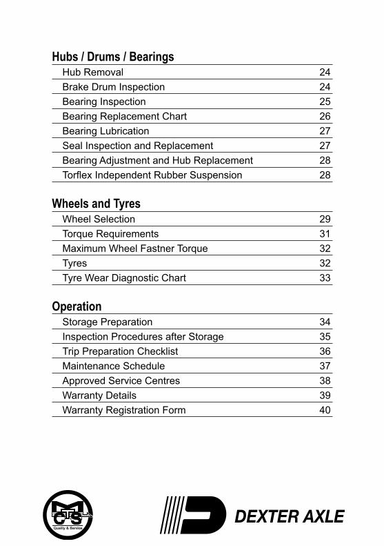
Hubs / Drums / BearingsHub Removal 24Brake Drum Inspection 24Bearing Inspection 25Bearing Replacement Chart 26Bearing Lubrication 27Seal Inspection and Replacement 27Bearing Adjustment and Hub Replacement 28Torflex Independent Rubber Suspension 28
Wheels and TyresWheel Selection 29Torque Requirements 31Maximum Wheel Fastner Torque 32Tyres 32Tyre Wear Diagnostic Chart 33
OperationStorage Preparation 34Inspection Procedures after Storage 35Trip Preparation Checklist 36Maintenance Schedule 37Approved Service Centres 38Warranty Details 39Warranty Registration Form 40
5
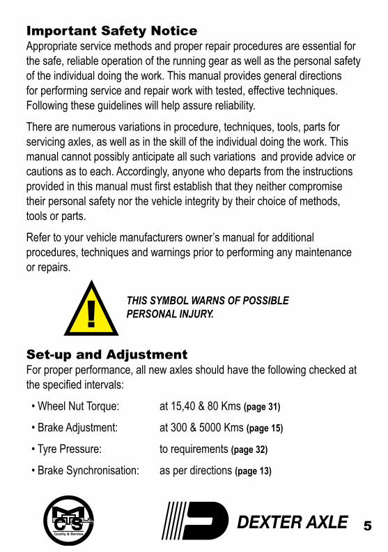
Important Safety NoticeAppropriate service methods and proper repair procedures are essential for the safe, reliable operation of the running gear as well as the personal safety of the individual doing the work. This manual provides general directions for performing service and repair work with tested, effective techniques. Following these guidelines will help assure reliability.
There are numerous variations in procedure, techniques, tools, parts for servicing axles, as well as in the skill of the individual doing the work. This manual cannot possibly anticipate all such variations and provide advice or cautions as to each. Accordingly, anyone who departs from the instructions provided in this manual must first establish that they neither compromise their personal safety nor the vehicle integrity by their choice of methods, tools or parts.
Refer to your vehicle manufacturers owner’s manual for additional procedures, techniques and warnings prior to performing any maintenance or repairs. THIS SYMBOL WARNS OF POSSIBLE PERSONAL INJURY.
Set-up and AdjustmentFor proper performance, all new axles should have the following checked at the specified intervals:
• Wheel Nut Torque: at 15,40 & 80 Kms (page 31)
• Brake Adjustment: at 300 & 5000 Kms (page 15)
• Tyre Pressure: to requirements (page 32)
• Brake Synchronisation: as per directions (page 13)
6
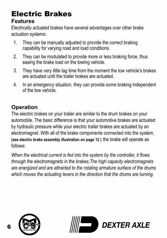
Electric BrakesFeaturesElectrically actuated brakes have several advantages over other brake actuation systems:1. They can be manually adjusted to provide the correct braking
capability for varying road and load conditions.2. They can be modulated to provide more or less braking force, thus
easing the brake load on the towing vehicle.3. They have very little lag time from the moment the tow vehicle’s brakes
are actuated until the trailer brakes are actuated.4. In an emergency situation, they can provide some braking independent
of the tow vehicle.
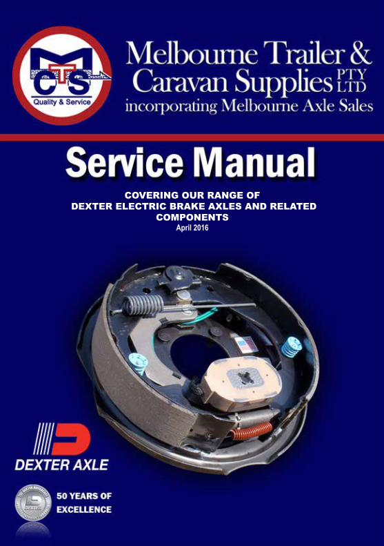
OperationThe electric brakes on your trailer are similar to the drum brakes on your automobile. The basic difference is that your automotive brakes are actuated by hydraulic pressure while your electric trailer brakes are actuated by an electromagnet. With all of the brake components connected into the system, (see electric brake assembly illustration on page 12 ) the brake will operate as follows:
When the electrical current is fed into the system by the controller, it flows through the electromagnets in the brakes.The high capacity electromagnets are energized and are attracted to the rotating armature surface of the drums which moves the actuating levers in the direction that the drums are turning.
7
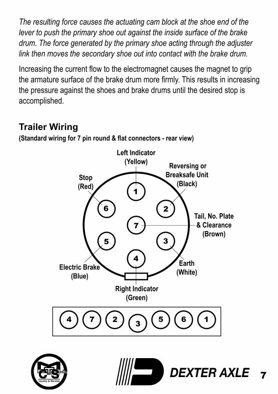
Left Indicator(Yellow) Reversing or
Breaksafe Unit(Black)
Tail, No. Plate& Clearance
(Brown)
Right Indicator(Green)
Earth(White)
Stop(Red)
Electric Brake(Blue)
The resulting force causes the actuating cam block at the shoe end of the lever to push the primary shoe out against the inside surface of the brake drum. The force generated by the primary shoe acting through the adjuster link then moves the secondary shoe out into contact with the brake drum.
Increasing the current flow to the electromagnet causes the magnet to grip the armature surface of the brake drum more firmly. This results in increasing the pressure against the shoes and brake drums until the desired stop is accomplished.
Trailer Wiring(Standard wiring for 7 pin round & flat connectors - rear view)
8
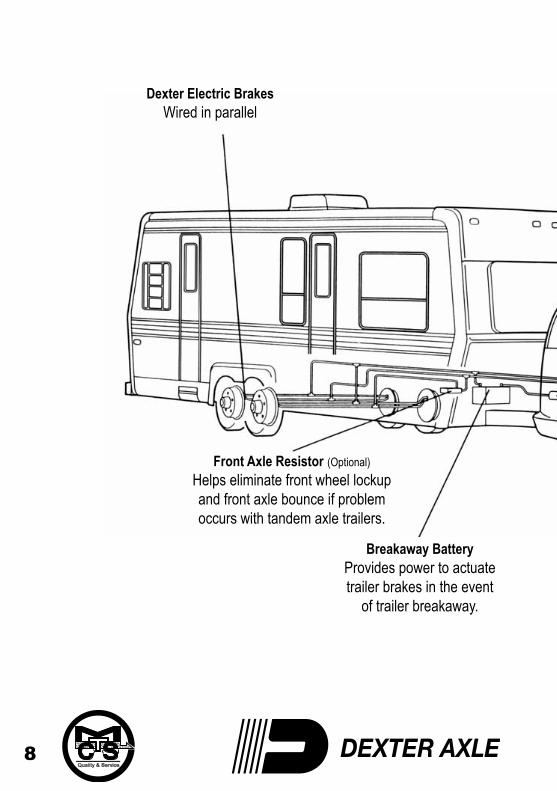
Dexter Electric BrakesWired in parallel
Front Axle Resistor (Optional)Helps eliminate front wheel lockupand front axle bounce if problemoccurs with tandem axle trailers.
Breakaway BatteryProvides power to actuatetrailer brakes in the event
of trailer breakaway.
9
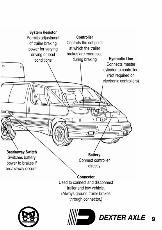
ControllerControls the set point
at which the trailerbrakes are energised
during braking
ConnectorUsed to connect and disconnect
trailer and tow vehicle.(Always ground trailer brakes
through connector.)
BatteryConnect controller
directly
System ResistorPermits adjustment
of trailer brakingpower for varying
driving or loadconditions Hydraulic Line
Connects mastercylinder to controller.
(Not required onelectronic controllers)
Breakaway SwitchSwitches batterypower to brakes ifbreakaway occurs.
10
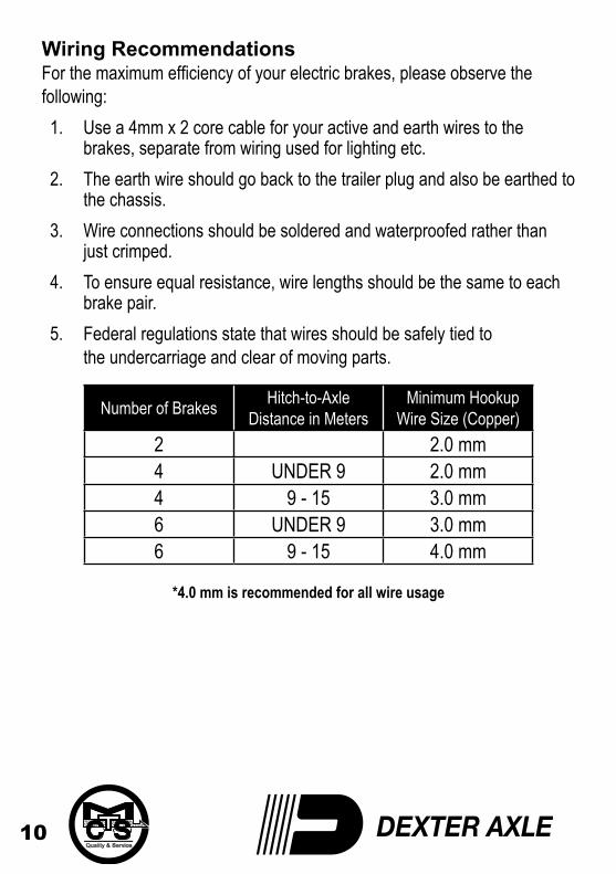
Wiring RecommendationsFor the maximum efficiency of your electric brakes, please observe the following:1. Use a 4mm x 2 core cable for your active and earth wires to the
brakes, separate from wiring used for lighting etc.2. The earth wire should go back to the trailer plug and also be earthed to
the chassis.3. Wire connections should be soldered and waterproofed rather than
just crimped.4. To ensure equal resistance, wire lengths should be the same to each
brake pair.5. Federal regulations state that wires should be safely tied to
the undercarriage and clear of moving parts.
Number of Brakes Hitch-to-AxleDistance in Meters
* Minimum Hookup Wire Size (Copper)
2 2.0 mm4 UNDER 9 2.0 mm4 9 - 15 3.0 mm6 UNDER 9 3.0 mm6 9 - 15 4.0 mm
*4.0 mm is recommended for all wire usage
11
Parking Brake OptionDexter electric brakes with parking option are mechanically operated by cable means. The cable attachment occurs outside of the brake backing plate. Cable force applied to the parking lever creates a torque through the pivot pin and cam assembly. Torque transferred to the parking cam results in a spreading force between the primary and secondary shoes. The shoes in turn, move towards the drum until contact is made. Friction generated between the drum and lining contact surface results in parking brake capability.
Use the cable adjuster to give sufficient tension to be able to set the handbrake lever on the last two notches of the coupling or handbrake when unladen. This needs to be checked again when the trailer or caravan is loaded. If the cable is too tight, the brakes will be applied as the axle moves backward under spring deflection.
Correct Use of Your Electric BrakesYour trailer brakes are designed to work in synchronisation with your tow vehicle brakes. Never use your tow vehicle or trailer brakes alone to stop the combined load. Your trailer and tow vehicle will seldom have the correct amperage flow to the brake magnets to give you comfortable, safe braking unless you make proper brake system adjustments. Changing trailer load and driving conditions, as well as uneven alternator and battery output, can mean unstable current flow to your brake magnets. It is therefore imperative that you maintain and adjust your brakes as set forth in this manual, use a properly modulated brake controller and perform the synchronisation procedure noted on page 13.
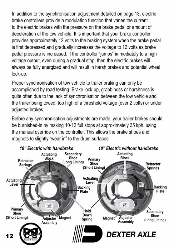
RetractorSprings
BackingPlateSecondary
Shoe(Long Lining)
AdjusterAssembly
Magnet
HoldDownSpring
PrimaryShoe
(Short Lining)
ActuatingLever
AdjusterSpring
RetractorSprings
RetractorSprings
BackingPlate
SecondaryShoe
(Long Lining)AdjusterAssembly
AdjusterAssembly
MagnetMagnetHoldDownSpring
PrimaryShoe
(Short Lining)
PrimaryShoe
(Short Lining)
ActuatingLever
ActuatingBlock
ActuatingLever
ActuatingBlock
BackingPlate
SecondaryShoe
(Long Lining)
12
10” Electric with handbrake 10” Electric without handbrake
In addition to the synchronisation adjustment detailed on page 13, electric brake controllers provide a modulation function that varies the current to the electric brakes with the pressure on the brake pedal or amount of deceleration of the tow vehicle. It is important that your brake controller provides approximately 12 volts to the braking system when the brake pedal is first depressed and gradually increases the voltage to 12 volts as brake pedal pressure is increased. If the controller “jumps” immediately to a high voltage output, even during a gradual stop, then the electric brakes will always be fully energized and will result in harsh brakes and potential wheel lock-up.Proper synchronisation of tow vehicle to trailer braking can only be accomplished by road testing. Brake lock-up, grabbiness or harshness is quite often due to the lack of synchronisation between the tow vehicle and the trailer being towed, too high of a threshold voltage (over 2 volts) or under adjusted brakes.Before any synchronisation adjustments are made, your trailer brakes should be burnished-in by making 10-12 full stops at approximately 35 kph, using the manual override on the controller. This allows the brake shoes and magnets to slightly “wear in” to the drum surfaces.
To SynchroniseTo ensure safe brake performance and synchronisation, read the brake controller manufacturer’s instructions completely before attempting any synchronisation procedure.
Before making road tests, make sure the area is clear of vehicular and pedestrian traffic.
Make several hard stops at 35 kph on a dry paved road free of sand and gravel. If the trailer brakes lock and slide, decrease the gain setting. Adjust the controller just to the point of impending brake lock-up and wheel skid.Note: Minimum vehicle stopping distances are achieved when wheels approach lock-up. Brake lock-up should be avoided as it results in poor vehicle stability and control. Depending on load, brake type, wheels and tyres, not all trailer brakes are capable of wheel lock-up.
If the controller is applying the trailer brakes before the tow vehicle brakes, then the controller level adjustment should be adjusted so the trailer brakes come on in synchronisation with the tow vehicle brakes. For proper braking performance, it is recommended that the controller be adjusted to allow the trailer brakes to come on just slightly ahead of the tow vehicle brakes. When proper synchronisation is achieved there will be no sensation of the trailer “jerking” or “pushing” the tow vehicle during braking.
Do not adjust this control outside the parameters outlined by the manufacturer’s instructions.
13
DANGER
DANGER
DANGER
DANGER
14
ControllersThere are several types and brands of Electric Brake Controllers available, however their method of operation falls into 3 basic categories:1. Solid State Controllers are the simplest and cheapest type with few,
if any, moving parts. This makes them easy to set, with some only involving an “ON—OFF” switch. These controllers are usually set to a time delay and an output amount (eg 70% output in minimum time). Once set this will apply to all braking situations. The downside to this type of controller is that they generally do not detect the rate of deceleration and therefore require constant adjustment to maintain an adequate braking force.
2. Trailer Mounted Controllers are available for situations where there are several tow vehicles for the one trailer. They do however require a constant 12 volt supply to the controller, either from the tow vehicle, or from a battery on the trailer. These are only legal in Australia for a trailer with a Gross Vehicle Mass of up 2000kg.These operate as per the solid state controller.
3. Inertia or Pendulum Type Controllers are the best choice for even proportional braking. Once activated by the brake light switch from the tow vehicle, they detect the rate of deceleration via a pendulum mechanism inside the controller. This in turn provides a variable voltage output to the Electromagnets resulting in a smooth, consistent braking effort. “This is the type of controller that Melbourne Trailer and Caravan Supplies Pty. Ltd. recommend.”
Start by making sure the trailer brakes are properly adjusted. (see page 15). Some controllers have a gain control to vary the amount of current to the brakes and a level control which sets the controller’s inertia sensor to sense deceleration. The level adjustment also can be used to vary the time at which the trailer braking is felt. The gain or output control adjustment usually controls the maximum amount of amperage available to the brakes. This can be adjusted for varying trailer loads.
15
DANGER
DANGER
GENERAL MAINTENANCEBrake AdjustmentBrakes should be adjusted (1) after the first 300 kms of operation when the brake shoes and drums have “seated,” (2) at 5000 kms intervals, (3) or as use and performance requires. The brakes should be adjusted in the following manner:1. Jack up the trailer and secure on adequate capacity jack stands.
Follow the trailer manufacturer’s recommendations for lifting and supporting the unit. Check that the wheel and drum rotate freely.
Never crawl under your trailer unless it is resting on properly placed jack stands. Do not lift or place supports on any part of the suspension system2. With a screwdriver or standard adjusting tool, rotate the starwheel of
the adjuster assembly to expand the brake shoes. Adjust the brake shoes out until the pressure of the linings against the drum makes the wheel very difficult to turn.
Note: With drop spindle axles, a modified adjusting tool with about an 80 degree angle should be used.3. Rotate the starwheel in the opposite direction until the wheel turns
freely with a slight lining drag.4. Lower the wheel to the ground.
5. Repeat the above procedure on all brakes.
16
DANGER
DANGER
Brake Cleaning and InspectionYour trailer brakes must be inspected and serviced at yearly intervals or more often as required by use and performance. Magnets and shoes must be changed when they become worn or scored to avoid inefficient vehicle braking.
Clean the backing plate, magnet arm, magnet and brake shoes. Make certain that all parts removed are replaced in the same brake and drum assembly. Inspect the magnet arm for any loose or worn parts. Check shoe return springs, hold down springs and adjuster springs for stretch or deformation and replace if required.
Brake LubricationBefore reassembling, apply a light film of Lubriplate or similar grease or antiseize compound on the brake anchor pin, the actuating arm bushing and pin and the areas on the backing plate that are in contact with the brake shoes and magnet lever arm. Apply a light film of oil on the actuating block mounted on the actuating arm.
Do not get grease or oil on the brake linings, drums or magnets.
17
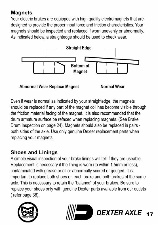
Abnormal Wear Replace Magnet Normal Wear
Bottom ofMagnet
Straight Edge
MagnetsYour electric brakes are equipped with high quality electromagnets that are designed to provide the proper input force and friction characteristics. Your magnets should be inspected and replaced if worn unevenly or abnormally. As indicated below, a straightedge should be used to check wear.
Even if wear is normal as indicated by your straightedge, the magnets should be replaced if any part of the magnet coil has become visible through the friction material facing of the magnet. It is also recommended that the drum armature surface be refaced when replacing magnets. (See Brake Drum Inspection on page 24). Magnets should also be replaced in pairs - both sides of the axle. Use only genuine Dexter replacement parts when replacing your magnets.
Shoes and LiningsA simple visual inspection of your brake linings will tell if they are useable.Replacement is necessary if the lining is worn (to within 1.5mm or less), contaminated with grease or oil or abnormally scored or gouged. It is important to replace both shoes on each brake and both brakes of the same axle. This is necessary to retain the “balance” of your brakes. Be sure to replace your shoes only with genuine Dexter parts available from our outlets ( refer page 38).
18
VOLTMETER
TROUBLESHOOTINGMost electric brake malfunctions that cannot be corrected by either brake adjustments or synchronisation adjustments can generally be traced to electrical system failure. Mechanical causes are ordinarily obvious, i.e bent or broken parts, worn out linings or magnets, seized lever arms or shoes, scored drums, loose parts, etc. Voltmeters and ammeters are essential tools for proper troubleshooting of electric brakes.
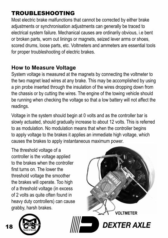
How to Measure VoltageSystem voltage is measured at the magnets by connecting the voltmeter to the two magnet lead wires at any brake. This may be accomplished by using a pin probe inserted through the insulation of the wires dropping down from the chassis or by cutting the wires. The engine of the towing vehicle should be running when checking the voltage so that a low battery will not affect the readings.
Voltage in the system should begin at 0 volts and as the controller bar is slowly actuated, should gradually increase to about 12 volts. This is referred to as modulation. No modulation means that when the controller begins to apply voltage to the brakes it applies an immediate high voltage, which causes the brakes to apply instantaneous maximum power.The threshold voltage of a controller is the voltage applied to the brakes when the controller first turns on. The lower the threshold voltage the smoother the brakes will operate. Too high of a threshold voltage (in excess of 2 volts as quite often found in heavy duty controllers) can cause grabby, harsh brakes.
19
AMMETER
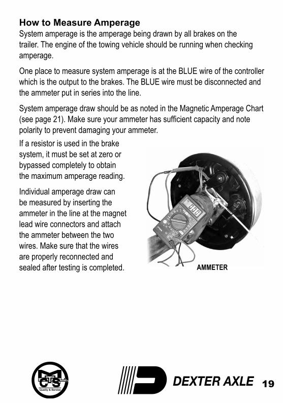
How to Measure AmperageSystem amperage is the amperage being drawn by all brakes on the trailer. The engine of the towing vehicle should be running when checking amperage.
One place to measure system amperage is at the BLUE wire of the controller which is the output to the brakes. The BLUE wire must be disconnected and the ammeter put in series into the line.
System amperage draw should be as noted in the Magnetic Amperage Chart (see page 21). Make sure your ammeter has sufficient capacity and note polarity to prevent damaging your ammeter.If a resistor is used in the brake system, it must be set at zero or bypassed completely to obtain the maximum amperage reading.
Individual amperage draw can be measured by inserting the ammeter in the line at the magnet lead wire connectors and attach the ammeter between the two wires. Make sure that the wires are properly reconnected and sealed after testing is completed.
20
By far, the most common electrical problem is low or no voltage and amperage at the brakes.Common causes of this condition are:1. Poor electrical connections.2. Open circuits.3. Insufficient wire gauge.4. Broken wires.5. Blown fuses (Fusing of brakes is not recommended).6. Faulty or damaged controllers or resistors.
Another common electrical problem is shorted or partially shorted circuits (indicated by abnormally high system amperage). These are occasionally the most difficult to find. Possible causes are:1. Shorted magnet coil.2. Defective controllers.3. Bare wires contacting a grounded object.
Finding the system short is a matter of isolation. If the high amperage reading drops to zero by unplugging the trailer, then the short is in the trailer. If the amperage reading remains high with all the brake magnets disconnected, the short is in the trailer wiring.
All electrical troubleshooting procedures should start at the controller.Most complaints regarding brake harshness or malfunction are traceable to improperly adjusted or non-functioning controllers. See your controller manufacturer’s data for proper adjustment and testing procedures. If the voltage and amperage is not satisfactory, proceed on to the connector and then to the individual magnets to isolate the problem source.
21
12 volts output at the controller should equate to 10.5 volts minimum at each magnet. Nominal system amperage at 12 volts with cold magnets, system resistor at zero and controller at maximum gain should be as detailed in the following chart:
Magnet Amperes Chart
Brake Size Amps / Magnet
Two Brakes
Four Brakes
Six Brakes
7 x 1 1/4
2.5
5.0
10.0
15.0
10 x 1 1/4
3.0
6.0
12.0
18.0
10 x 2 1/4
3.0
6.0
12.0
18.0
12 x 2
3.0
6.0
12.0
18.0
12 1/4 x 2 1/2
3.0
6.0
12.0
18.0
12 1/4 x 3 3/8
3.0
6.0
12.0
18.0
22
SYMPTOMNo Brakes
WeakBrakes
LockingBrakes
IntermittentBrakes
CAUSESOpen Circuits
Severe Under-adjustment
Faulty Controller
Short Circuits
Grease or Oil on Magnets or Linings
Corroded Connections
Worn Linings or Magnets
Scored or Grooved Brake Drums
Improper Synchronisation
Under-adjustment
Glazed Linings
Overloaded Trailer
Improper Synchronisation
Under-adjustment
Faulty Controller
Loose, Bent or Broken Brake Components
Out-of-Round Brake Drums
Insufficient Wheel Load
Faulty Controller
Broken Wires
Loose Connections
Faulty Ground
REMEDIESFind & Correct
Adjust Brakes
Test & Correct
Find & Correct
Clean & Replace
Clean & Correct Cause of Corrosion
Replace
Machine or Replace
Correct
Adjust Brakes
Re-burnish or Replace
Correct
Correct
Adjust
Test & Correct
Replace Components
Machine or Replace
Adjust System Resistor & Synchronise
Test & Correct
Repair or Replace
Find & Repair
Find & Repair
Troubleshooting
SYMPTOMBrakes Pullto One Side
HarshBrakes
NoisyBrakes
SurgingBrakes
DraggingBrakes
CAUSESWrong Magnet Lead Wire Colour
Incorrect Adjustment
Grease or Oil on Linings or Magnets
Broken Wires
Bad Connections
Under-adjustment
Improper Synchronisation
Improper Controller
Faulty Controller
Under-adjustment
Lack of Lubrication
Broken Brake Component
Incorrect Brake Component
Grease or Oil on Linings or Magnets
Out-of-Round or Cracked Brake Drums
Faulty Controller
Over-adjustment
Out-of-Round Brake Drums
Incorrect Brake Components
Loose, Bent or Broken Brake Components
Loose Wheel Bearing Adjustment
Faulty Breakaway Switch
Bent Axle
REMEDIESCorrect
Adjust
Clean & Replace
Find & Repair
Find & Repair
Adjust
Correct
Change
Test & Correct
Adjust
Lubricate
Replace Component
Replace Component
Clean or Replace
Machine or Replace
Test & Correct
Re-adjust
Machine or Replace
Replace
Replace
Adjust
Repair or Replace
Replace Axle
23

24
HUBS, DRUMS AND BEARINGSHub RemovalWhenever the hub equipment on your axle must be removed for inspection or maintenance the following procedure should be utilized:1. Elevate and support the trailer unit as per the manufacturer’s
instructions.2. Remove the wheel.3. Remove the grease cap by carefully prying around the flange of the
cap. If the hub is an oil lube type, then the cap can be removed by unscrewing it counterclockwise while holding the hub stationary.
4. Remove the cotter pin from the axle nut or in the case of E-Z Lube versions, bend the locking tang to the free position.
5. Unscrew the axle nut (counterclockwise) and remove the axle washer.6. Remove the hub from the axle, being careful not to allow the outer
bearing cone to fall out. The inner bearing cone will be retained by the seal.
Brake Drum InspectionThere are two areas of the brake drum that are subject to wear and require periodic inspection. These two areas are the drum surface where the brake shoes make contact during stopping and the armature surface where the magnet contacts.
The drum surface should be inspected for excessive wear or heavy scoring. If worn more than 0.5mm oversized, or the drum has worn out of round by more than 0.4mm, then the drum surface should be turned. If scoring or other wear is greater than 2.3mm on the diameter, the drum must be replaced.
25
When turning the drum surface, the maximum rebore diameter is as follows:
7” Brake Drum - 180mm 10” Brake Drum - 256mm 12” Brake Drum - 307mm 12 1/4” Brake Drum - 313mm
The machined inner surface of the brake drum that contacts the brake magnet is called the armature surface. If the armature surface is scored or worn unevenly, it should be remachined by removing not more than .076mm of material. To insure proper contact between the armature face and the magnet face, the magnets should be replaced whenever the armature surface is refaced and the armature surface should be refaced whenever the magnets are replaced. Note: It is important to protect the wheel bearing bores from metallic chips and contamination which results from drum turning or armature refacing operations. Make certain that the wheel bearing cavities are clean and free of contamination before reinstalling bearing and seals The presence of these contaminants will cause premature wheel bearing failure.
Bearing InspectionWash all grease and oil from the bearing cone using a suitable solvent. Dry the bearing with a clean, lint-free cloth and inspect each roller completely. If any pitting, corrosion or other signs of damage are present, then the bearing must be replaced. The bearing cup inside the hub must be inspected.IMPORTANT: Bearings must always be replaced in sets of a cup and a cone.
26
DANGER
DANGER
BEARING CUP REMOVAL TECHNIQUE
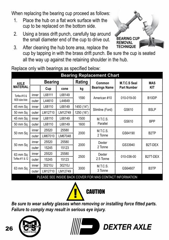
When replacing the bearing cup proceed as follows:1. Place the hub on a flat work surface with the
cup to be replaced on the bottom side.2. Using a brass drift punch, carefully tap around
the small diameter end of the cup to drive out.3. After cleaning the hub bore area, replace the
cup by tapping in with the brass drift punch. Be sure the cup is seated all the way up against the retaining shoulder in the hub.
Replace only with bearings as specified below:Bearing Replacement Chart
AXLEMATERIAL
Bearing Rating Common Bearings Name
M.T.C.S Seal Part Number
MAS KITCup cone kg
Torflex #10 & M35 tube Axle
inner L68111 L681491590 American #10 010-019-00 B10DP
outer L44610 L4464945 mm Sq inner L68110 L68149 1450 (14”)
Slimline (Ford) GS610 BSLP50 mm Sq outer LM12710 LM12749 1250 (16”) 45 mm Sq inner L68110 L68149 1500 M.T.C.S.
Parallel GS610 BPP50 mm Sq outer L68110 L68149 1600
50 mm Sqinner 25520 25580
2000 M.T.C.S. 2 Tonne GS64190 B2TP
outer LM67010 LM67048
50 mm Sqinner 25520 25580
2000 Dexter 2 Tonne GS33940 B2T-DEX
outer 15245 15123
63 mm SqTorflex #11 & 12
inner 25520 255802500 Dexter
2.5 Tonne 010-036-00 B27T-DEX outer 15245 15123
63 mm Sqinner 30210J 30210J
3000 M.T.C.S. 3 Tonne GS64607 B3TP
outer LM12710 LM12749PLEASE SEE INSIDE BACK COVER FOR MAS CONTACT INFORMATION
Be sure to wear safety glasses when removing or installing force fitted parts. Failure to comply may result in serious eye injury.
27
Bearing Lubrication Along with bearing adjustment, proper lubrication is essential to the current function and reliability of your trailer axle. Bearings should be lubricated every 12 months or 20,000 kms. The method to repack bearing cones is as follows:1. Place a quantity of grease into the palm of your hand.2. Press a section of the widest end of the bearing into the outer edge of
the grease pile closest to the thumb forcing grease into the interior of the bearing.
3. Repeat this while rotating the bearing from roller to roller.4. Continue this process until you have the entire bearing completely
filled with grease.
5. Before reinstalling, apply a light coat of grease on the bearing cup.
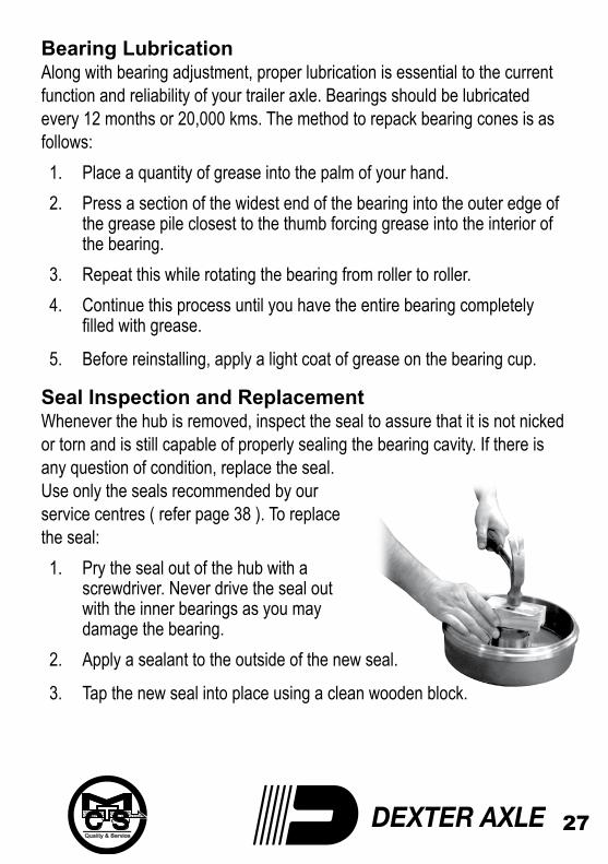
Seal Inspection and ReplacementWhenever the hub is removed, inspect the seal to assure that it is not nicked or torn and is still capable of properly sealing the bearing cavity. If there is any question of condition, replace the seal. Use only the seals recommended by our service centres ( refer page 38 ). To replace the seal:1. Pry the seal out of the hub with a
screwdriver. Never drive the seal out with the inner bearings as you may damage the bearing.
2. Apply a sealant to the outside of the new seal.
3. Tap the new seal into place using a clean wooden block.
28
Bearing Adjustment and Hub ReplacementIf the hub has been removed or bearing adjustment is required, the following adjustment procedure must be followed:1. After placing the hub, bearings, washers and axle nut back on the
axle stub in reverse order as detailed in the previous section on hub removal, rotate the hub assembly slowly while tightening the axle nut to approximately 65N.m (300mm wrench or pliers with full hand force).
2. Then loosen the axle nut to remove the torque. Do not rotate the hub.3. Finger tighten the axle nut until just snug.4. Back the axle nut out slightly until the first castellation lines up with the
split pin key hole and insert the split pin (or locking tang in the case of E-Z lube).
5. Bend over the split pin legs to secure the nut (or locking tang in the case of E-Z Lube).
6. Nut should be free to move with only restraint being the split pin (or locking tang).
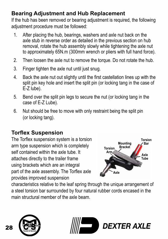
Torflex SuspensionThe Torflex suspension system is a torsion arm type suspension which is completely self contained within the axle tube. It attaches directly to the trailer frame using brackets which are an integral part of the axle assembly. The Torflex axle provides improved suspension characteristics relative to the leaf spring through the unique arrangement of a steel torsion bar surrounded by four natural rubber cords encased in the main structural member of the axle beam.
MountingBracket
TorsionBar
TorsionArm
Axle
AxleTube
29
DANGER
DANGER
The wheel hub axle is attached to a lever, called the torsion arm, which is fastened to the rubber encased bar. As load is applied, the bar rotates causing a rolling / compressive resistance in the rubber cords. This action provides the same functions as conventional sprung axles with several operating advantages including independent suspension.
Except for periodic inspection of the fasteners used to attach the Torflex axle to the vehicle frame, no other suspension maintenance is required on Torflex axles. They are of course, subject to the maintenance and inspection procedures regarding brakes, hubs, bearings, seals, wheels and tyres as outlined in this manual.
DO NOT WELD ON THE TORFLEX BEAM. It has rubber cords inside and the heat generated by welding could damage the cords
WHEELS AND TYRESWheel SelectionWheels are a very important and critical component of your running gear system. When specifying or replacing your trailer wheels, it is important that the wheels, tyres and axle are properly matched. The following characteristics are extremely important and should be thoroughly checked when replacement wheels are considered.1. Bolt Circle. Many bolt circle dimensions are available and some vary
by so little that it might be possible to attach an improper wheel that does not match the axle hub. Be sure to match your wheel to the axle hub.
2. Capacity. Make sure that the wheels have enough load carrying capacity and pressure rating to match the maximum load of the tyre and trailer.
30
DANGER
DANGER
DANGER
DANGER
3. Offset. This refers to the relationship of the center line of the tyre to the hub face of the axle. Care should be taken to match any replacement wheel with the same offset wheel as originally equipped. Failure to match offset can result in reducing the load carrying capacity of your axle.
4. Rim Contour.
Use only the approved rim contours as shown in the tyre manufacturers catalogue. The use of other rim contours is dangerous. Failure to use the proper rim contour can result in explosive separation of the tyre and wheel and could cause a serious accident.
Do not attempt to repair or modify a wheel. Even minor modifications can have a great effect. Do not install a tube to correct a leak through the rim. If the rim is cracked, the air pressure in the tube may cause the pieces of the rim to explode with great force and can cause serious injury or death.
31
8 BOLT4 BOLT 5 BOLT 6 BOLT
Torque RequirementsIt is extremely important to apply and maintain proper wheel mounting torque on your trailer axle. Torque is a measure of the amount of tightening applied to a fastener (nut or bolt) and is expressed as force times length. For example, a force of 400 Newtons applied at the end of wrench 300mm long will yield a torque of 120N.m. Torque wrenches are the best method to assure the proper amount of torque is being applied to a fastener.Note: Wheel nuts or bolts must be applied and maintained at the proper torque levels to prevent loose wheels, broken studs and possible dangerous separation of wheels from your axle.
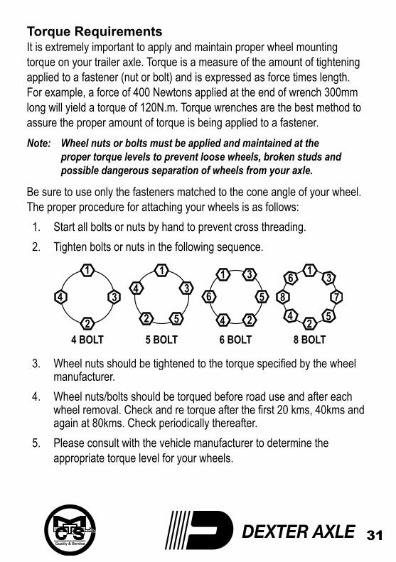
Be sure to use only the fasteners matched to the cone angle of your wheel. The proper procedure for attaching your wheels is as follows:1. Start all bolts or nuts by hand to prevent cross threading.2. Tighten bolts or nuts in the following sequence.
3. Wheel nuts should be tightened to the torque specified by the wheel manufacturer.
4. Wheel nuts/bolts should be torqued before road use and after each wheel removal. Check and re torque after the first 20 kms, 40kms and again at 80kms. Check periodically thereafter.
5. Please consult with the vehicle manufacturer to determine the appropriate torque level for your wheels.
32
DANGER
DANGER
Maximum Wheel Fastener TorqueThe wheel mounting studs used on Melbourne Trailer and Caravan Supplies axles conform to the SAE standards for grade 8. The maximum torque level that can be safely applied to these studs is listed in the following chart;
Stud Size Max. Torque 1/2” – 20 UNF, class 2A 120 lb.ft. 9/16”– 18 UNF, class 2A 170 lb.ft. 5/8” – 18 UNF, class 2A 325 lb.ft. 1.00 lb.ft.= 1.36 / N.m
Exceeding the above listed torque limits can damage studs and / or nuts and lead to eventual fractures and dangerous wheel separation.
Tyres Before mounting tyres onto wheels make certain that the rim size and contour is approved for the tyre as shown in the tyre manufacturer’s catalogue. Also make sure the tyre will carry the rated load. If the load is not equal on all tyres due to trailer weight distribution, use the tyre rated for the heaviest wheel position.Note: The capacity rating modulated into the sidewall of the tyre is not always the proper rating for the tyre if used in a trailer application.
Use the following guideline:1. LT and ST tyres. Use the capacity rating moulded into the tyre.2. Passenger Car Tyres. Use the capacity rating modulated into the tyre
sidewall divided by 1.10.3. Use tyre mounting procedures as outlined by the Rubber
Manufacturer’s Association or the tyre manufacturers.
33
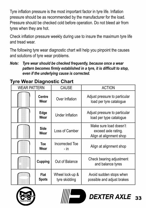
Tyre inflation pressure is the most important factor in tyre life. Inflation pressure should be as recommended by the manufacturer for the load. Pressure should be checked cold before operation. Do not bleed air from tyres when they are hot.
Check inflation pressure weekly during use to insure the maximum tyre life and tread wear.
The following tyre wear diagnostic chart will help you pinpoint the causes and solutions of tyre wear problems.Note: Tyre wear should be checked frequently, because once a wear pattern becomes firmly established in a tyre, it is difficult to stop, even if the underlying cause is corrected.
Tyre Wear Diagnostic ChartWEAR PATTERN CAUSE ACTION
Centre Wear Over Inflation Adjust pressure to particular
load per tyre catalogue
Edge Wear Under Inflation Adjust pressure to particular
load per type catalogue
Side Wear Loss of Camber
Make sure load doesn’texceed axle rating.
Align at alignment shop
Toe Wear
Incorrected Toe - in Align at alignment shop
Cupping Out of Balance Check bearing adjustmentand balance tyres
Flat Spots
Wheel lock-up &tyre skidding
Avoid sudden stops whenpossible and adjust brakes
34
DANGER
DANGER
OPERATIONStorage PreparationIf your trailer is to be stored for an extended period of time or over the winter, it is important that the trailer be prepared properly.1. Remove the emergency breakaway battery and store inside, out of the
weather. Charge the battery at least every 90 days.2. Jack up the trailer and place jack stands under the trailer frame so that
the weight will be off the tyres. Follow trailer manufacturer’s guidelines to lift and support the unit. Never jack up or place jack stands on the axle or on the equalizers.
Do not get grease or oil on brake linings or magnet face
3. Lubricate mechanical moving parts such as the hitch and suspension parts, that are exposed to the weather.
4. Boat trailer axles are subject to repeated immersion. Before storing, remove brake drums; clean, dry and relubricate moving brake components; inspect bearings - clean and relubricate.
Note: On oil lubricated hubs the upper part of the roller bearings are not immersed in an oil and are subject to potential corrosion. For maximum bearing life it is recommended that you revolve your wheels periodically (every 2-3 weeks) during periods of prolonged storage.
35
Inspection Procedures after StorageBefore removing trailer from jack stands:1. Remove all wheels and hubs or brake drums. Note which stub axle
and brake that the drum was removed from so that it can be reinstalled in the same location.
2. Inspect suspension for wear.3. Check tightness of hanger bolt, shackle bolt and U-bolt nuts per
recommended torque values.4. Check brake linings, brake drums and armature faces for excessive
wear or scoring.5. Check brake magnets with an ohmmeter. The magnets should check
3.2 ohms. If shorted or worn excessively, replace.6. Lubricate all brake moving parts using high temperature brake
lubricant 7. Remove any rust from braking surface and armature surface of
drums with fine emery paper or crocus cloth. Protect bearings from contamination while so doing.
8. Inspect oil or grease seals for wear or nicks. Replace if necessary.9. Lubricate hub bearings. Refer to procedure in manual.10. Reinstall hubs and adjust bearings per instructions in manual.
11. Mount and tighten wheels per Wheel Manufacturers Specifications.
36
Trip Preparation ChecklistThere are a number of simple rules to follow in caring for your trailer axle assembly that can add to its life - and in the case of some of these rules, you may be protecting your own life as well. Using the following checklist before starting a trip with your trailer is highly recommended. Some of these items should be checked 2-3 weeks prior to planned trip to allow sufficient time to perform maintenance.
1. Check your maintenance schedule and be sure you are up-to-date.2. Check hitch. Is it showing wear? Is it properly lubricated?3. Fasten safety chains securely and where fitted, breakaway switch
actuating chain. Make certain the breakaway battery is fully charged.4. Inspect towing hookup for secure attachment.5. Load your trailer so that approximately 10% of the trailers total weight
is on the hitch. For light trailers this should be increased to 15%.6. Do not overload. Stay within your gross vehicle rated capacity.
(Consult your trailer’s identification plate).7. Inflate tyres according to manufacturer’s specifications; inspect tyres
for cuts, excessive wear, etc.8. Check wheel mounting nuts/bolts with a torque wrench. Torque, in
proper sequence, to the levels specified by the Wheel Manufacturer.9. Make certain brakes are synchronised and functioning properly.10. Check tightness of hanger bolt, shackle bolt and U-bolts nuts.11. Check operation of all lights.12. Check that your trailer is towing in a level position and adjust
hitch height if required.
37
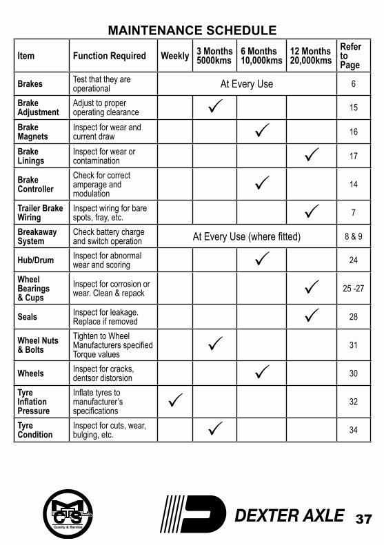
MAINTENANCE SCHEDULE
Item Function Required Weekly 3 Months5000kms
6 Months10,000kms
12 Months20,000kms
Referto Page
Brakes Test that they areoperational At Every Use 6
BrakeAdjustment
Adjust to properoperating clearance P 15
BrakeMagnets
Inspect for wear andcurrent draw P 16
BrakeLinings
Inspect for wear orcontamination P 17
BrakeController
Check for correctamperage and modulation P 14
Trailer BrakeWiring
Inspect wiring for barespots, fray, etc. P 7
BreakawaySystem
Check battery charge and switch operation At Every Use (where fitted) 8 & 9
Hub/Drum Inspect for abnormalwear and scoring P 24
WheelBearings& Cups
Inspect for corrosion orwear. Clean & repack P 25 -27
Seals Inspect for leakage.Replace if removed P 28
Wheel Nuts& Bolts
Tighten to WheelManufacturers specifiedTorque values P 31
Wheels Inspect for cracks, dentsor distorsion P 30
TyreInflationPressure
Inflate tyres tomanufacturer’sspecifications P 32
TyreCondition
Inspect for cuts, wear,bulging, etc. P 34
38
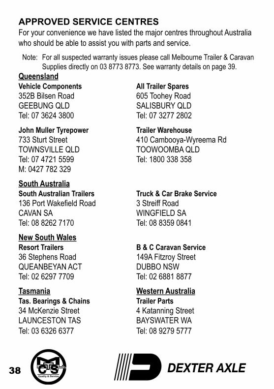
APPROVED SERVICE CENTRESFor your convenience we have listed the major centres throughout Australia who should be able to assist you with parts and service.
Note: For all suspected warranty issues please call Melbourne Trailer & Caravan Supplies directly on 03 8773 8773. See warranty details on page 39.
Queensland Vehicle Components All Trailer Spares 352B Bilsen Road 605 Toohey Road GEEBUNG QLD SALISBURY QLD Tel: 07 3624 3800 Tel: 07 3277 2802John Muller Tyrepower Trailer Warehouse 733 Sturt Street 410 Cambooya-Wyreema Rd TOWNSVILLE QLD TOOWOOMBA QLD Tel: 07 4721 5599 Tel: 1800 338 358 M: 0427 782 329South Australia South Australian Trailers Truck & Car Brake Service 136 Port Wakefield Road 3 Streiff Road CAVAN SA WINGFIELD SA Tel: 08 8262 7170 Tel: 08 8359 0841New South Wales Resort Trailers B & C Caravan Service 36 Stephens Road 149A Fitzroy Street QUEANBEYAN ACT DUBBO NSW Tel: 02 6297 7709 Tel: 02 6881 8877Tasmania Western Australia Tas. Bearings & Chains Trailer Parts 34 McKenzie Street 4 Katanning Street LAUNCESTON TAS BAYSWATER WA Tel: 03 6326 6377 Tel: 08 9279 5777
39
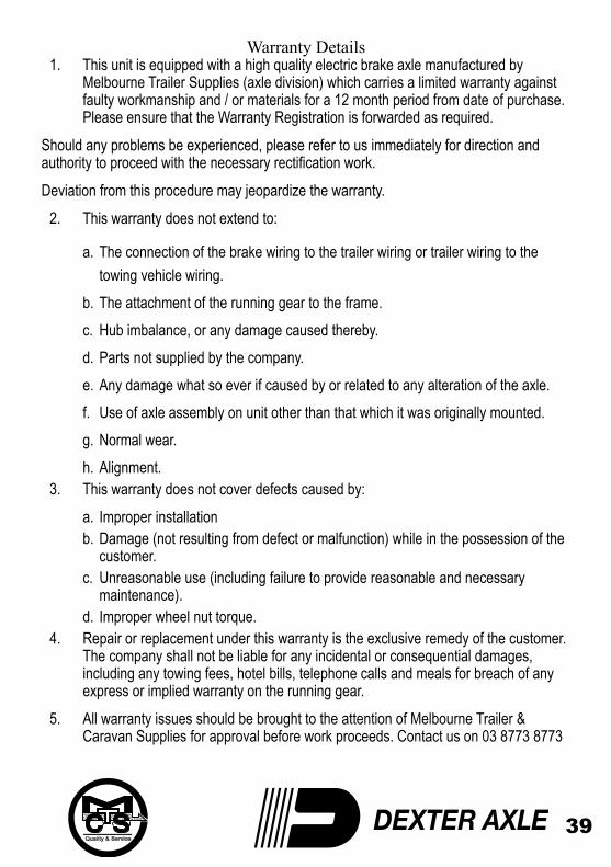
Warranty Details1. This unit is equipped with a high quality electric brake axle manufactured by
Melbourne Trailer Supplies (axle division) which carries a limited warranty against faulty workmanship and / or materials for a 12 month period from date of purchase. Please ensure that the Warranty Registration is forwarded as required.
Should any problems be experienced, please refer to us immediately for direction and authority to proceed with the necessary rectification work.Deviation from this procedure may jeopardize the warranty.
2. This warranty does not extend to:
a. The connection of the brake wiring to the trailer wiring or trailer wiring to the towing vehicle wiring.
b. The attachment of the running gear to the frame.c. Hub imbalance, or any damage caused thereby.d. Parts not supplied by the company.e. Any damage what so ever if caused by or related to any alteration of the axle.f. Use of axle assembly on unit other than that which it was originally mounted.g. Normal wear.h. Alignment.
3. This warranty does not cover defects caused by:a. Improper installationb. Damage (not resulting from defect or malfunction) while in the possession of the
customer.c. Unreasonable use (including failure to provide reasonable and necessary
maintenance).d. Improper wheel nut torque.
4. Repair or replacement under this warranty is the exclusive remedy of the customer. The company shall not be liable for any incidental or consequential damages, including any towing fees, hotel bills, telephone calls and meals for breach of any express or implied warranty on the running gear.
5. All warranty issues should be brought to the attention of Melbourne Trailer & Caravan Supplies for approval before work proceeds. Contact us on 03 8773 8773
40
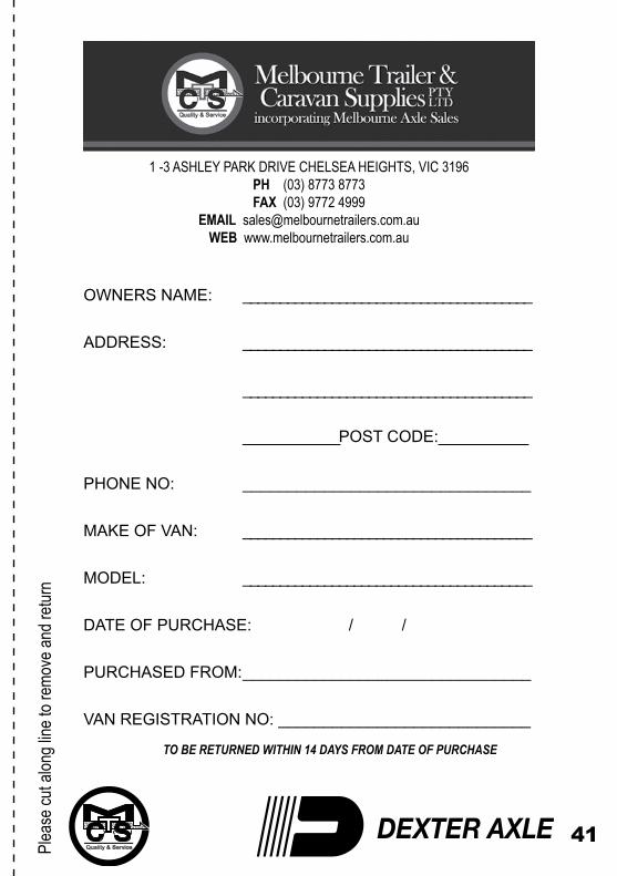
1 -3 ASHLEY PARK DRIVE CHELSEA HEIGHTS, VIC 3196PH (03) 8773 8773 FAX (03) 9772 4999
EMAIL [email protected] www.melbournetrailers.com.au
WARRANTY REGISTRATION
OWNERS NAME: _______________________________________
ADDRESS: _______________________________________
_______________________________________
_____________POST CODE:____________
PHONE NO: ________________________________
MAKE OF VAN: ________________________________
MODEL: ________________________________
DATE OF PURCHASE: / /
PURCHASED FROM: ________________________________
VAN REGISTRATION NO: _________________________Please Complete and Retain As your copy
A.B.N. 87 005 646 202
41
Plea
se cu
t alon
g line
to re
move
and r
eturn
1 -3 ASHLEY PARK DRIVE CHELSEA HEIGHTS, VIC 3196PH (03) 8773 8773 FAX (03) 9772 4999
EMAIL [email protected] www.melbournetrailers.com.au
OWNERS NAME: _______________________________________
ADDRESS: _______________________________________
_______________________________________
_____________POST CODE:____________
PHONE NO: ________________________________
MAKE OF VAN: _______________________________________
MODEL: _______________________________________
DATE OF PURCHASE: / /
PURCHASED FROM: ________________________________
VAN REGISTRATION NO: ____________________________
TO BE RETURNED WITHIN 14 DAYS FROM DATE OF PURCHASE

WE RECOMMEND
DEXTER & MAS QUALITY REPLACEMENT PARTS
1-3 ASHLEY PARK DRIVECHELSEA HEIGHTS VIC. 3196
PHONE: (03) 8773 8773 FAX: (03) 9772 4999
www.melbournetrailers.com.auemail: [email protected]


![Yamaha FZ6 Sercive Manual [2003] and Supplementary Sercive Manual [2004]](https://img.dokumen.tips/doc/110x75/5695cf3a1a28ab9b028d2669/yamaha-fz6-sercive-manual-2003-and-supplementary-sercive-manual-2004.jpg)