Embed Size (px)
DESCRIPTION
Course Wrap-up. Priority Encoder Revisited What (We Hope) You Learned Design Methodology Final Exam Information. =1. =0. Let’s Try the Priority Encoder One More Time …. KI. 0. KI. I 3. O 3. I j. O j. KO. 0. I 2. O 2. KO. I 1. O 1. 1. I 0. O 0. KI 0 1. Oj Ij 0. KO Ij - PowerPoint PPT Presentation
Citation preview
CS 150 - Spring 2007 – Lecture #29: Recap - 1
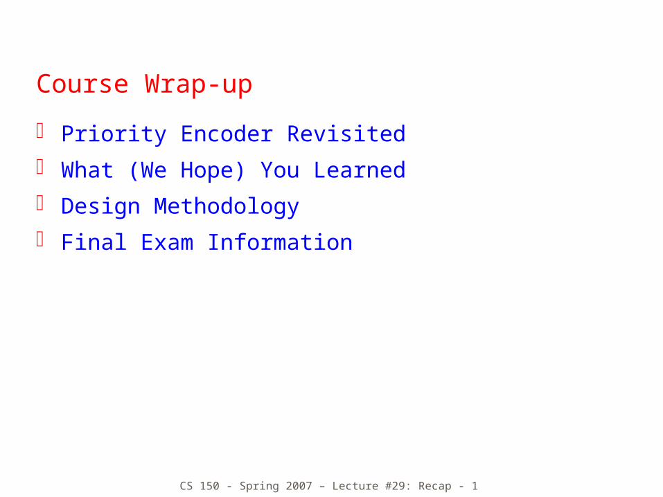
Course Wrap-up
Priority Encoder Revisited
What (We Hope) You Learned
Design Methodology
Final Exam Information
CS 150 - Spring 2007 – Lecture #29: Recap - 2
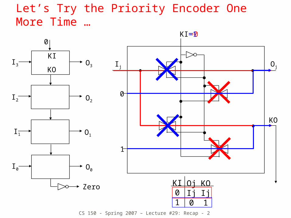
Let’s Try the Priority Encoder One More Time …
I3
I2
I1
I0
O3
O2
O1
O0
Zero
0
KI
KO
0
1
Ij Oj
KO
KI
KI01
OjIj0
KOIj1
=0=1
CS 150 - Spring 2007 – Lecture #29: Recap - 3
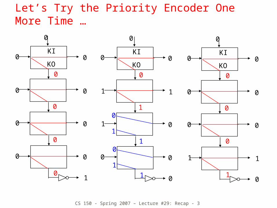
Let’s Try the Priority Encoder One More Time …
0
1
1
0
0
KI
KO0
0
1
1
00
11
0
0
0
11
0
0
0
0
0
KI
KO0
0
0
0
0
0
0
1
0
KI
KO
0
0
1
0
0
0
0
0
0
0
10
0
1
CS 150 - Spring 2007 – Lecture #29: Recap - 4
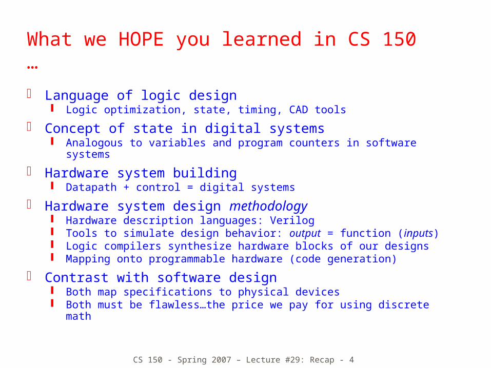
What we HOPE you learned in CS 150 …
Language of logic design Logic optimization, state, timing, CAD tools
Concept of state in digital systems Analogous to variables and program counters in software
systems
Hardware system building Datapath + control = digital systems
Hardware system design methodology Hardware description languages: Verilog Tools to simulate design behavior: output = function (inputs) Logic compilers synthesize hardware blocks of our designs Mapping onto programmable hardware (code generation)
Contrast with software design Both map specifications to physical devices Both must be flawless…the price we pay for using discrete
math
CS 150 - Spring 2007 – Lecture #29: Recap - 6
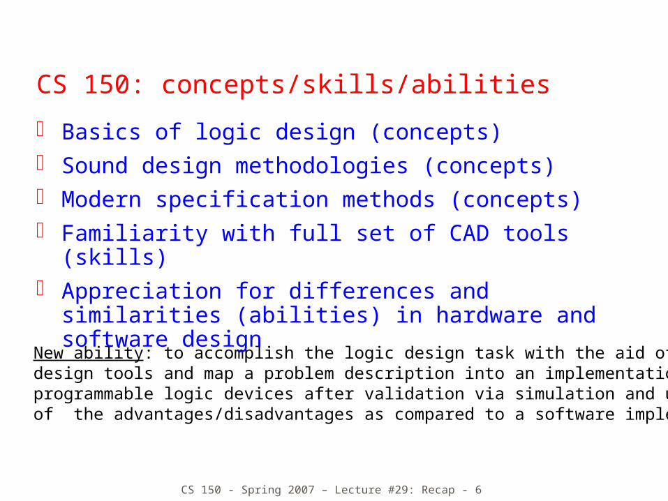
New ability: to accomplish the logic design task with the aid of computer-aideddesign tools and map a problem description into an implementation withprogrammable logic devices after validation via simulation and understandingof the advantages/disadvantages as compared to a software implementation
CS 150: concepts/skills/abilities
Basics of logic design (concepts) Sound design methodologies (concepts) Modern specification methods (concepts) Familiarity with full set of CAD tools (skills)
Appreciation for differences and similarities (abilities) in hardware and software design

CS 150 - Spring 2007 – Lecture #29: Recap - 7
Representation of Digital Designs
Physical devices (transistors, relays)
Switches
Truth tables
Boolean algebra
Gates
Waveforms
Finite state behavior
Register-transfer behavior
Concurrent abstract specifications
Simulation, Chipscope& Complex System
Description (e.g., SDRAM)
VerilogStructural & BehaviorialDescriptions
CS 150 - Spring 2007 – Lecture #29: Recap - 8
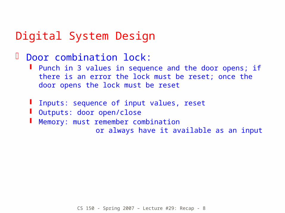
Digital System Design
Door combination lock: Punch in 3 values in sequence and the door opens; if
there is an error the lock must be reset; once the door opens the lock must be reset
Inputs: sequence of input values, reset Outputs: door open/close Memory: must remember combination
or always have it available as an input
CS 150 - Spring 2007 – Lecture #29: Recap - 9
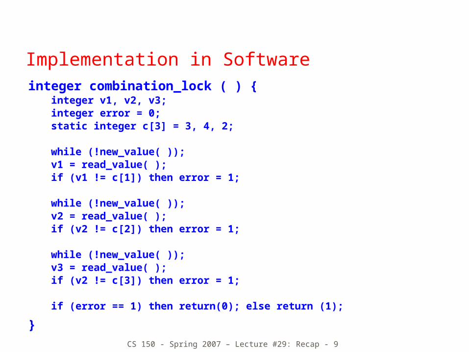
Implementation in Softwareinteger combination_lock ( ) {
integer v1, v2, v3;integer error = 0;static integer c[3] = 3, 4, 2;
while (!new_value( ));v1 = read_value( );if (v1 != c[1]) then error = 1;
while (!new_value( ));v2 = read_value( );if (v2 != c[2]) then error = 1;
while (!new_value( ));v3 = read_value( );if (v2 != c[3]) then error = 1;
if (error == 1) then return(0); else return (1);
}
CS 150 - Spring 2007 – Lecture #29: Recap - 10
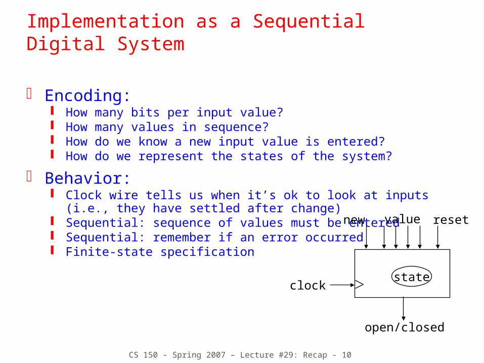
Implementation as a Sequential Digital System
Encoding: How many bits per input value? How many values in sequence? How do we know a new input value is entered? How do we represent the states of the system?
Behavior: Clock wire tells us when it’s ok to look at inputs
(i.e., they have settled after change) Sequential: sequence of values must be entered Sequential: remember if an error occurred Finite-state specification
resetvalue
open/closed
new
clockstate
CS 150 - Spring 2007 – Lecture #29: Recap - 11
closed closedclosedC1=value& new
C2=value& new
C3=value& new
C1!=value& new C2!=value
& newC3!=value& new
closed
reset
not newnot newnot new
S1 S2 S3 OPEN
ERR
open
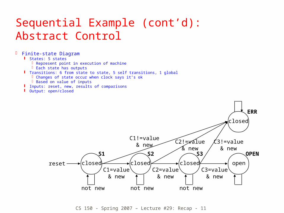
Sequential Example (cont’d):Abstract Control Finite-state Diagram
States: 5 states Represent point in execution of machine Each state has outputs
Transitions: 6 from state to state, 5 self transitions, 1 global Changes of state occur when clock says it’s ok Based on value of inputs
Inputs: reset, new, results of comparisons Output: open/closed
CS 150 - Spring 2007 – Lecture #29: Recap - 12
reset
open/closed
new
C1 C2 C3
comparator
value
equal
multiplexer
equal
controllermux control
clock
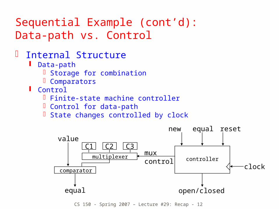
Sequential Example (cont’d):Data-path vs. Control
Internal Structure Data-path
Storage for combinationComparators
ControlFinite-state machine controllerControl for data-pathState changes controlled by clock
CS 150 - Spring 2007 – Lecture #29: Recap - 13
closed
closedmux=C1reset equal
& new
not equal& new
not equal& new
not equal& new
not newnot newnot new
S1 S2 S3 OPEN
ERR
closedmux=C2 equal
& new
closedmux=C3 equal
& new
open
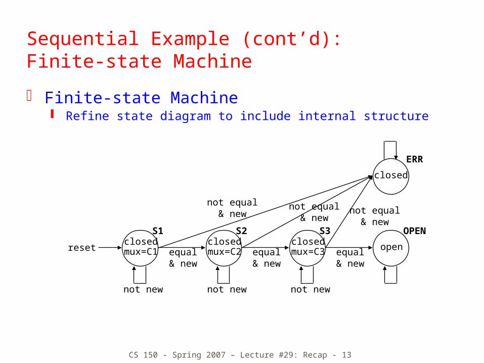
Sequential Example (cont’d):Finite-state Machine
Finite-state Machine Refine state diagram to include internal structure
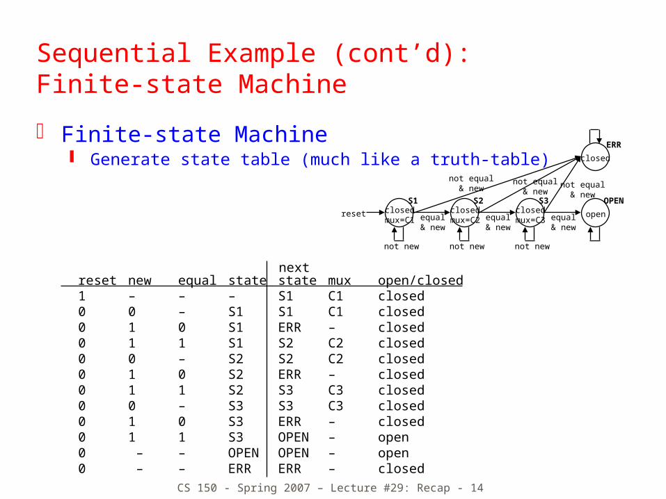
CS 150 - Spring 2007 – Lecture #29: Recap - 14
reset new equal state state mux open/closed1 – – – S1 C1 closed0 0 – S1 S1 C1 closed0 1 0 S1 ERR – closed0 1 1 S1 S2 C2 closed0 0 – S2 S2 C2 closed0 1 0 S2 ERR – closed0 1 1 S2 S3 C3 closed0 0 – S3 S3 C3 closed0 1 0 S3 ERR – closed0 1 1 S3 OPEN – open 0 – – OPEN OPEN – open0 – – ERR ERR – closed
next
Sequential Example (cont’d):Finite-state Machine
Finite-state Machine Generate state table (much like a truth-table) closed
closedmux=C1
reset equal& new
not equal& new
not equal& new
not equal& new
not newnot newnot new
S1 S2 S3 OPEN
ERR
closedmux=C2 equal
& new
closedmux=C3 equal
& new
open
CS 150 - Spring 2007 – Lecture #29: Recap - 15
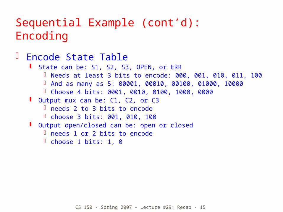
Sequential Example (cont’d):Encoding
Encode State Table State can be: S1, S2, S3, OPEN, or ERR
Needs at least 3 bits to encode: 000, 001, 010, 011, 100 And as many as 5: 00001, 00010, 00100, 01000, 10000 Choose 4 bits: 0001, 0010, 0100, 1000, 0000
Output mux can be: C1, C2, or C3 needs 2 to 3 bits to encode choose 3 bits: 001, 010, 100
Output open/closed can be: open or closed needs 1 or 2 bits to encode choose 1 bits: 1, 0
CS 150 - Spring 2007 – Lecture #29: Recap - 16
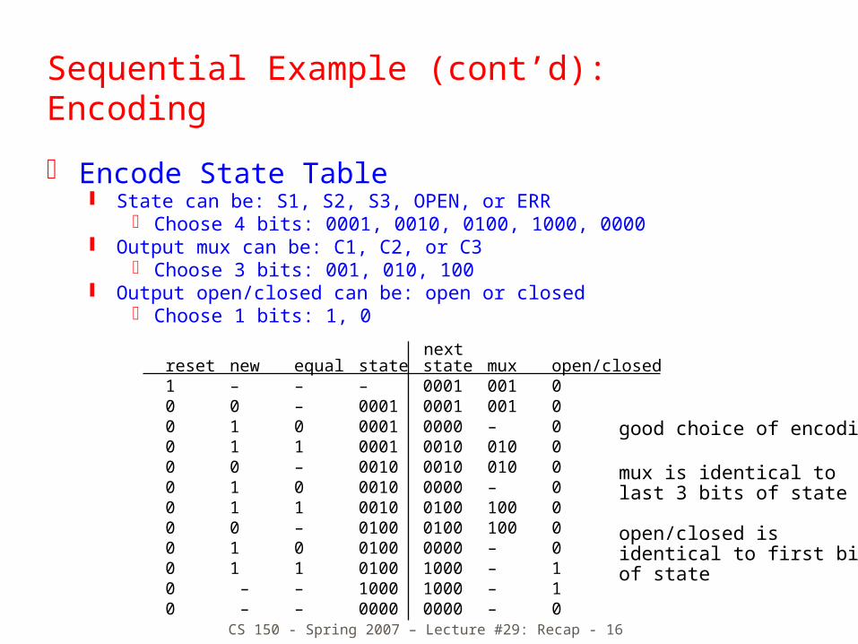
good choice of encoding!
mux is identical to last 3 bits of state
open/closed isidentical to first bitof state
Sequential Example (cont’d):Encoding
Encode State Table State can be: S1, S2, S3, OPEN, or ERR
Choose 4 bits: 0001, 0010, 0100, 1000, 0000 Output mux can be: C1, C2, or C3
Choose 3 bits: 001, 010, 100 Output open/closed can be: open or closed
Choose 1 bits: 1, 0
reset new equal state state mux open/closed1 – – – 0001 001 0 0 0 – 0001 0001 001 00 1 0 0001 0000 – 00 1 1 0001 0010 010 0 0 0 – 0010 0010 010 00 1 0 0010 0000 – 00 1 1 0010 0100 100 0 0 0 – 0100 0100 100 00 1 0 0100 0000 – 00 1 1 0100 1000 – 1 0 – – 1000 1000 – 10 – – 0000 0000 – 0
next
CS 150 - Spring 2007 – Lecture #29: Recap - 17
reset
open/closed
new equal
controllermux control
clock
reset
open/closed
new equal
mux control
clock
comb. logic
state
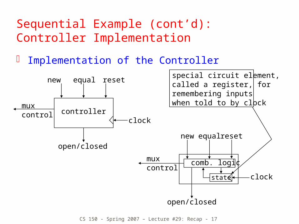
special circuit element, called a register, for remembering inputswhen told to by clock
Sequential Example (cont’d):Controller Implementation
Implementation of the Controller

CS 150 - Spring 2007 – Lecture #29: Recap - 18
digital system
data-path control
stateregisters
combinationallogic
multiplexercomparatorcode
registers
register logic
switchingnetworks
Design Hierarchy
CS 150 - Spring 2007 – Lecture #29: Recap - 19
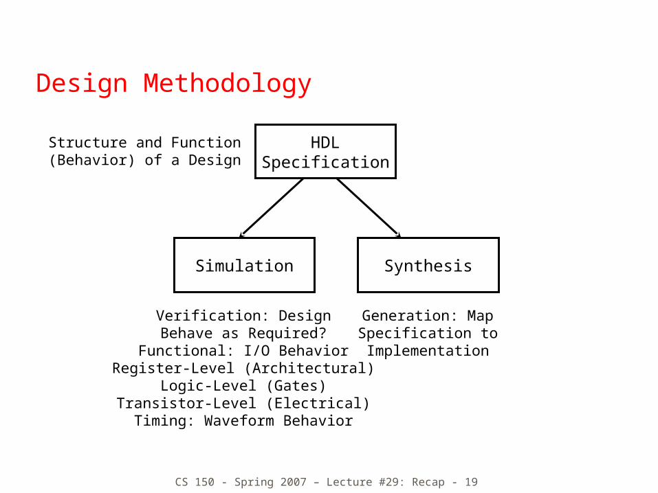
Design Methodology
HDLSpecification
Structure and Function(Behavior) of a Design
Simulation
Verification: DesignBehave as Required?
Functional: I/O BehaviorRegister-Level (Architectural)
Logic-Level (Gates)Transistor-Level (Electrical)Timing: Waveform Behavior
Synthesis
Generation: MapSpecification toImplementation
CS 150 - Spring 2007 – Lecture #29: Recap - 20
Combinational Logic Implementation
K-map method to map truth tables into minimized gate level descriptions
Alternative implementation approaches: Two-level logic, multi-level logic, logic
implementation with multiplexers Programmable logic in the form of PLAs, ROMs, Muxes,
… Field programmable logic in the form of devices like
Xilinx
Combinational logic building blocks Arithmetic and logic units, including
adders/subtractors and other arithmetic functions (e.g., combinational multipliers)
CS 150 - Spring 2007 – Lecture #29: Recap - 21
Sequential Logic Implementation
Models for representing sequential circuits Abstraction of sequential elements Finite state machines and their state diagrams Inputs/outputs Mealy, Moore, and synchronous Mealy machines
Finite state machine design procedure Deriving state diagram Deriving state transition table Determining next state and output functions Implementing combinational logic
Sequential logic building blocks Registers, Register files (with multiple read and write
ports), Shifters, Counters, RAMs Arbitrators
CS 150 - Spring 2007 – Lecture #29: Recap - 22
State Machine Implementation
Partitioned State Machines Ways to organize single complex monolithic state
machine into simpler, interacting state machines based on functional partitioningTime state approach offers one conceptual methodMuch more relevant is what you likely did in your course project
Issues of synchronization across independently clocked subsystems Synchronization of signals Four cycle handshake
CS 150 - Spring 2007 – Lecture #29: Recap - 23
Final Exam Information
Exam Group 2
Friday, May 11, 12:30-3:30 PM
Room: 145 Dwinelle

CS 150 - Spring 2007 – Lecture #29: Recap - 24
Final Exam Information
(Long) Design Specification in English for an “interesting” digital subsystem Function described in terms of desired input/output
behavior You will need to be able to hand generate waveform diagrams
to demonstrate that you understand the design specification!
You may have to partition the subsystem into control and datapath Design the control part as one or more interacting Finite
State Machines State Diagrams as well as Verilog for control
Design the datapath blocks Behavioral Verilog mostly, but gate level hand-drawn schematics for some selected parts
You may have to revise the design to improve its performance
For an example, see http://hkn.eecs.berkeley.edu/student/online/cs/150/2000/fa-f.html

CS 150 - Spring 2007 – Lecture #29: Recap - 25
Past Final Exams
Fall 2005: Statistics Coprocessor Spec for calculation inside processor Handshake for processor-coprocessor communications High Level Design, Datapath Components, Coprocessor State
Machine, Verilog Description
Spring 2004: Content-Addressable Memory Memory interface and functional specification High Level Design, Datapath Components, Memory Controller
State Machine, Verilog Description, Performance Improvement
Spring 2001: Elevator System Complex system behavior High Level Design, Datapath Components, Controller State
Machine, Extend from 1 to 2 elevators, microprogrammed implementation

CS 150 - Spring 2007 – Lecture #29: Recap - 26
Final Exam Information
The Exam is conceptual and DESIGN-skills oriented The Exam is not about obscure details of
technologies like the Xilinx or Actel internal architectures
The best way to study for The Exam is to review your course project and to reflect on the process you went through in designing and implementing it!
The Exam design problem won’t be a video conferencing system -- it will be some kind of digital system with control and a datapath that can be specified in a couple of pages of English text!
You will need to write a lot for this Exam! Bring multiple pencils, erasers, rulers, AND AT LEAST TWO BLUE BOOKs!!! You won’t need a computer or a calculator!
Open course textbook and open course notes. They probably won’t help you much ;-)


![M3P Course Wrap [SlideShare]](https://img.dokumen.tips/doc/110x75/55baca99bb61eb37568b4664/m3p-course-wrap-slideshare.jpg)