Embed Size (px)
Citation preview

Grant Agreement No. 619572
COSIGN
Combining Optics and SDN In next Generation data centre Networks Programme: Information and Communication Technologies Funding scheme: Collaborative Project – Large-Scale Integrating Project
Deliverable D1.5
Roadmap studies
Due date of deliverable: 30. June 2015 Actual submission date: 15. July 2015
Start date of project: January 1, 2014 Duration: 36 months Lead contractor for this deliverable: DTU, Michael Berger
COSIGN
Project co-funded by the European Commission within the Seventh Framework Programme Dissemination Level
PU Public X PP Restricted to other programme participants (including the Commission Services) RE Restricted to a group specified by the consortium (including the Commission Services) CO Confidential, only for members of the consortium (including the Commission Services)
Ref. Ares(2015)2995000 - 16/07/2015

619572 - ICT COSIGN [PUBLIC] D1.5 Combining Optics and SDN In next Generation data centre Networks
Page 2 of 55
Legal Notice
The information in this document is subject to change without notice.
The Members of the COSIGN Consortium make no warranty of any kind with regard to this document, including, but not limited to, the implied warranties of merchantability and fitness for a particular purpose. The Members of the COSIGN Consortium shall not be held liable for errors contained herein or direct, indirect, special, incidental or consequential damages in connection with the furnishing, performance, or use of this material.
Possible inaccuracies of information are under the responsibility of the project. This report reflects solely the views of its authors. The European Commission is not liable for any use that may be made of the information contained therein.
619572 - ICT COSIGN [PUBLIC] D1.5 Combining Optics and SDN In next Generation data centre Networks
Page 3 of 55
Executive Summary D1.5 constitutes the final deliverable of COSIGN work package 1 (WP1). The deliverable covers three main areas, namely a description of the COSIGN approach in relation to the latest state of the art for data centre networks; a comparison and benchmarking of the COSIGN approach to other research and industrial optical data centre network proposals; and roadmap studies and strategies for the involved industrial partners’ products and services for a 5-10 year timeframe.
The first part of the deliverable focuses on presenting an updated view on the state of the art in data centre networks. In particular, the state of the art presented in the COSIGN description of work (DoW) at the project start is revisited and updated where necessary.
Further on, the COSIGN solution is evaluated and benchmarked against other optical DCN solutions, both industrial as well as academic. The consortium has chosen to compare its proposal against six solutions, which all have received significant attention in the industrial and/or the research community.
Finally the deliverable provides industrial data centre network roadmaps, strategies and a techno-economic analysis of the involved industrial partners’ value proposition. The aim is to providing a 5-10 year outlook based on industry and analyst reports and positions the industrial partners’ foreseen products and services in the data centre network value chain. Roadmaps, strategies and techno-economic analyses are presented for all main focus areas of the COSIGN project.

619572 - ICT COSIGN [PUBLIC] D1.5 Combining Optics and SDN In next Generation data centre Networks
Page 4 of 55
Document Information
Status and Version: Final Date of Issue: 15/7/2015 Dissemination level: PUBLIC Author(s): Name Partner Michael Berger DTU Sarah Ruepp DTU Amaia Legarrea I2CAT Eduard Escalona I2CAT José I. Aznar I2CAT Tim Durrant Venture Oren Marmur PhotonX Giada Landi NXW Giacomo Bernini NXW Gino Carrozzo NXW Bingli Guo UNIVBRIS Salvatore Spadaro UPC Alessandro Predieri IRT Katherine Barabash IBM Anna Levin IBM Oded Raz TU/e Lars Grüner-Nielsen OFS Marco Petrovich ORC Nick Parsons Polatis Edited by: Michael Berger DTU Checked by : Alessandro Predieri IRT Tim Durrant Venture Sarah Ruepp DTU
619572 - ICT COSIGN [PUBLIC] D1.5 Combining Optics and SDN In next Generation data centre Networks
Page 5 of 55
Table of Contents Executive Summary .............................................................................................................................. 3
Table of Contents .................................................................................................................................. 5
1 Introduction ..................................................................................................................................... 7
1.1 Background and content ............................................................................................................. 7
1.2 Reference Material ..................................................................................................................... 7 1.2.1 Reference Documents ....................................................................................................... 7 1.2.2 Acronyms and Abbreviations ........................................................................................... 8
1.3 Document History ...................................................................................................................... 8
2 Current state-of-the-art in data centre development .................................................................. 9
2.1 Introduction – Key technical areas relevant to COSIGN ........................................................... 9
2.2 Data Centre Network Architectures ........................................................................................... 9
2.3 TOR switch and 3D stacked Transceiver ................................................................................. 11
2.4 Novel Fibres enabling high data capacity interconnects .......................................................... 12
2.5 High port count low latency optical network switches ............................................................. 14 2.5.1 LCoS based Optical Switch ............................................................................................ 14 2.5.2 Micro-Electro-Mechanical Systems Switches ................................................................ 15 2.5.3 Semiconductor Optical Amplifier based Optical Switch ................................................ 16 2.5.4 Optical Cross Point Switch ............................................................................................. 18 2.5.5 Electro Optic Switches ................................................................................................... 19 2.5.6 Beam-Steering Optical Switch........................................................................................ 20 2.5.7 Comparison Analysis and summary ............................................................................... 21
2.6 Converged IT and network orchestration ................................................................................. 22
2.7 Virtualization technologies ....................................................................................................... 23
3 COSIGN solutions evaluated against existing solutions ............................................................ 26
3.1 Calient ...................................................................................................................................... 26
3.2 Helios ........................................................................................................................................ 27
3.3 Plexxi ........................................................................................................................................ 28
3.4 MIMO OFDM .......................................................................................................................... 29
3.5 Data Vortex .............................................................................................................................. 30
3.6 Petabit ....................................................................................................................................... 31
3.7 COSIGN comparison summary ................................................................................................ 32
4 Industrial DCN Roadmaps, Strategies and Techno-economic Analysis .................................. 35
4.1 DCN virtualization, orchestration, and control ........................................................................ 35 4.1.1 DCN virtualization .......................................................................................................... 35 4.1.2 DCN orchestration .......................................................................................................... 37 4.1.3 DCN control.................................................................................................................... 40
4.2 DCN switching technologies .................................................................................................... 41 4.2.1 Fast optical Switch .......................................................................................................... 41 4.2.2 High Capacity Circuit Switching .................................................................................... 42 4.2.3 High Radix ToR Switches .............................................................................................. 43

619572 - ICT COSIGN [PUBLIC] D1.5 Combining Optics and SDN In next Generation data centre Networks
Page 6 of 55
4.3 Fibre technologies for optical DCNs ........................................................................................ 46
4.4 DCN architecture and inventory ............................................................................................... 47
5 Conclusion ..................................................................................................................................... 52
6 References ...................................................................................................................................... 53
619572 - ICT COSIGN [PUBLIC] D1.5 Combining Optics and SDN In next Generation data centre Networks
Page 7 of 55
1 Introduction
1.1 Background and content Data Centre networks are in the state of ever increasing evolution. Many new technologies, architectures and modes of operation are currently being proposed in this vibrant area of research and industrial development. The focus area of the COSIGN project is to combine optics and SDN for next generation data centre networks. Specifically, COSIGN aims at designing and demonstrating a data centre network architecture built over innovative optical technologies combined with SDN based network control and service orchestration for future-proof, dynamic, on demand, low-latency and ultra-high bandwidth intra-data centre applications. The aim of this deliverable is thus to present a roadmap for data centre network development for the next 5-10 years. The study includes both a technological comparison of different industrial solutions and their comparison to the COSIGN approach, as well as a techno-economic analysis of the envisioned products and services from the industrial partners involved in the COSIGN project.
In order to provide a solid foundation for future data centre roadmaps, the first part of the deliverable (Section 2) focuses on presenting an updated view on the state of the art in data centre networks. In particular, the state of the art presented in the COSIGN description of work (DoW) at the project start is revisited and updated where necessary. The considered topics are data centre network architectures, TOR switches and 3D stacked transceivers, novel fibres for high data capacity interconnects, high port count low latency optical network switches, converged IT and network orchestration and virtualization technologies. For each topic, any updates compared to the state of the art presented in the DoW are described, including possible enhancements over the course of the last two years (i.e., since the DoW was written). Thereafter, the proposed COSIGN approach is validated and possibly updated in relation to current state of the art.
In Section 3, the COSIGN solution is evaluated and benchmarked against other optical DCN solutions, both industrial as well as academic. The consortium has chosen to compare its proposal against six solutions, which all have received significant attention in the industrial and/or the research community, namely: Calient [Calient], Helios [Helios], Plexxi [Plexi], MIMO OFDM [ofdm-dcn-2012], Data Vortex [dv-mcn-2007] and Petabit [petabit-2010]. For each of these proposals, the section first contains a description of their main features and operations mode, and then the proposals are benchmarked to the COSIGN approach in terms of the following network Technologies: high radix TOR switch with optical interconnects, SDM based fibres, optical fast switching (ns), large scale optical switch, SDN control, path computation and network service virtualization.
Section 4 presents industrial data centre network roadmaps, strategies and a techno-economic analysis of the involved industrial partners’ value proposition. The section aims at providing a 5-10 year outlook based on industry and analyst reports and positions the industrial partners’ foreseen products and services in the data centre network value chain. Roadmaps, strategies and techno-economic analyses are presented for all main focus areas of the COSIGN project, namely: data centre network virtualization, orchestration and control; data centre network switching technologies; fibre technologies for optical data centre networks; and data centre network architecture and inventory.
Based on the results and analyses presented in this document, Section 5 draws conclusions and summarises how the COSIGN approach is positioned in terms of both latest state of the art as well as techno-economic considerations for the next 5-10 year timeframe.
1.2 Reference Material
1.2.1 Reference Documents [1] COSIGN FP7 Collaborative Project Grant Agreement Annex I – “Description of
Work” [2] COSIGN WP1 Deliverable D1.1 Requirements for next generation intra-Data

619572 - ICT COSIGN [PUBLIC] D1.5 Combining Optics and SDN In next Generation data centre Networks
Page 8 of 55
Centres network design [3] COSIGN WP1 Deliverable D1.2 Comparative analysis of optical technologies for
Intra-Data Centres network. [4] COSIGN WP1 Deliverable D1.3 Comparative analysis of control plane
alternatives. [5] COSIGN WP1 Deliverable D1.4 Architecture Design.
1.2.2 Acronyms and Abbreviations Most frequently used acronyms in the Deliverable are listed below. Additional acronyms can be specified and used throughout the text.
AAA Authentication, Authorisation, Accounting API Application Programming Interface AWG Array Waveguide Grating DC Data Centre DCN Data Centre Network GMPLS Generalized Multi-Protocol Label Switch IETF Internet Engeneering Task Force IT Information Technologies MCF Multicore Fibre MPO Multipath Push On NE Network Element NIC Network Interface Card NVE Network Virtualization Edges NVO Network Virtualization Overlay LCoS Liquid Crystal on Silicon OCS Optical Circuit Switching OF Open Flow OPS Optical Packet Switching OSNR Optical Signal to Noise Ratio OXS Optical Crosspoint Switch PBGF Photonic Band Gap Fibre PCB Printed Circuit Board QoS Quality of Service REST Representational State Transfer SDN Software Defined Networking SLA Service Level Agreement SMF Single Mode Fibre TDM Time Division Multiplexing ToR Top of the Rack VCSEL Vertical Cavity Surface Emitting Lasers WSS Wavelength Selective Switch
1.3 Document History Version Date Authors Comment 1.0 19-06-2015
See the list of authors
First draft for circulation 2.0 03-07-2015 For internal review 2.0_revIRT 08-07-2015 Review from Interoute 2.0_revIRT_VP 12-07-2015 Review from Venture 2.1_rev_SRRU 14-07-2015 Review from Quality Mgmt. 3.0 15-07-2015 Final
619572 - ICT COSIGN [PUBLIC] D1.5 Combining Optics and SDN In next Generation data centre Networks
Page 9 of 55
2 Current state-of-the-art in data centre development
2.1 Introduction – Key technical areas relevant to COSIGN COSIGN consortium aims to move from typical 2-tier and 3-tier hierarchical intra-Data Centre (DC) topologies towards flattered network infrastructures with high bandwidth and low latency. By the time the COSIGN partnership was established, a number of optical technologies, Software Defined Networking- (SDN)-based control frameworks and cloud orchestration platforms were proposed as flagships of the DC-architecture model. In this section, WP1 partners review the technologies that were proposed as “beyond the state of the art” at the time the COSIGN proposal was edited, and analyze potential changes and deviations experienced during the last two years. To address this, the technologies of the Description of Work (DoW) document [1] have been revisited as well as technologies in D1.2 [3] and D1.3 [4]. More specifically: Data Centre Network (DCN) Architectures, ToR Switches, Data Centre Network Architectures fibres, High port count low latency optical network switches, Converged IT + Network orchestration and virtualization techniques.
2.2 Data Centre Network Architectures The typical DCN architecture is based on multi-level hierarchical topology using cost-effective Ethernet (Infiniband) electronics switches [Cisco]. Numerous DCN architectures have been proposed in recent years, e.g. Fat Tree [Al-Fares], DCell [DCell], BCube [BCube], Helios [Helios], etc. As the size and complexity of the data centres keep growing, in order to accommodate the ever-increasing demand of applications, scaling out the data centre network infrastructure becomes one of the most challenging issues. The traditional tree-like network topology has an inherent disadvantage that causes the bottlenecks in latency and bandwidth. Nevertheless, during the last two years, there has been a rapid development within the field, with numerous proposals for novel Data centre network architectures [Kachris, Mhamdi]. The newest solutions leverage the latest technology developments in the fields of optical components, advanced optical switching architectures and/or improvements in the traditional electronic architectures in terms of better flow control, improved routing mechanisms etc. The authors of [Xiaomen] and [MatrixDCN] provide an overview of some of the latest advancements within the field of improving the operations of traditional electronic data centres. Solutions focus on optimized flow scheduling and routing, as well as on improved utilization of the multi-path capabilities, present in traditional data centre architectures. In this line of solutions, the authors of [Microsoft] present an interesting combination of SDN, improvements of existing protocols, Remote Direct Memory Access (RDMA) advanced load balancing and DiffServ QoS approaches to create a scalable and effective DC network. Furthermore, the latest DC deployment of Facebook is presenting some spectacular advances in the field, offering unprecedented scalability based on multi-level disaggregation in novel electronic packet switched architecture called data centre fabric topology [FB]. Within the field of optical (either all-optical or hybrid) data centres there have been several proposals: • OSA [OSA]: provides highly-dynamic reconfigurable channel switched architecture; • WDM-PON [WDM]: exploits a hybrid solution combining passive optical network architecture
for inter-rack communication and traditional Ethernet switching for intra-rack communication; • Space-WL [WL]: proposes a novel space-wavelength switched architecture; • STIA [STIA]: proposes a novel space-time interconnection architecture; • FISSION [Fission]: combines optical bus architecture together with modified Carrier Ethernet
protocol for connectivity supporting millions of servers;
619572 - ICT COSIGN [PUBLIC] D1.5 Combining Optics and SDN In next Generation data centre Networks
Page 10 of 55
• LIONS [LIONS]: proposes a passive arrayed waveguide grating router (AWGR)-based low-latency interconnect optical network switch for high-performance data centre;
• TONAK LION [TONAK LION]: proposes an active AWGR based switch (an advanced version of the LIONS switch), together with a distributed all-optical token and all-optical NACK (Negative Acknowledgement) architectures.
• MIMO-OFDM [MIMO]: introduces a novel data centre network architecture based on cyclic Arrayed Waveguide Grating (AWG) device, Multiple-Input Multiple-Output (MIMO) Orthogonal Frequency Division Multiplexing (OFDM) technology and parallel signal detection.
• Data Vortex [dc-mcn-2007]: Distributed interconnection network for High Performance Computing and data centre interconnects.
• Petabit [petabit-2010]: Exploits buffer-less optical switch based on a 3 stage clos network. • LIGHTNESS [LIGHTNESS]: introduces a hybrid all-optical Optical Packet Switching (OPS) (for
short-lived flows)/Optical Circuit Switching (OCS) (for long-lived flows) architecture combined with SDN control for intra-DC connectivity services.
• All-to-all [All-to-All]: proposes a flexible-bandwidth all-to-all optical interconnect architecture for data centres exploiting wavelength routing in AWGRs and fast tuneable lasers.
• NEPHELE [NEPHELE]: A recently started H2020 project that aims at a dynamic hybrid optical network infrastructure for future scale-out, disaggregated data centres. NEPHELE proposes the adoption of an Ethernet optical TDMA data centre network, controlled through SDN technologies to enable application-aware intra-DC connectivity.
Furthermore, commercial products utilizing optical technologies are already available [Plexxi, Calient, Polatis]. These commercial solutions are, among other optical DCN solutions, described in more detail in section 3. Also, the latest trend within the DC architecture field consists of disaggregating the data centre. Almost all major industry players in the field have proposed solutions supporting the disaggregation of components and functionalities (e.g. Cisco’s Unified Computing System (UCS), Huawei’s HTC-DC [HW], Facebook’s Wedge and SixPack together with the data centre fabric topology [FB]). Several levels of disaggregation have been proposed, focusing either on component disaggregation or functionality disaggregation or both. The main objective of the disaggregation process is pooling the physical DC resources (compute, storage and networking) together for more effective management. The unit-element of the DC is no longer the server, but instead a pod of equal-type elements (e.g., of memory or CPU cards) [DDC]. Numerous challenges have been identified both in the data plane and in the control and management plane for realizing this novel DC architecture trend, but the advantages in terms of improved resource usage, increased manageability and scalability, and the potential for providing novel services within the DC have not been disputed by any of the major players in the field, which indicates a clear trend in the commercial world. Moreover, it is worth mentioning another trend within DC interconnect design – geographically distributed micro DCs and virtual DC. The convergence of the inter- and the intra-DC architectures presents interesting possibilities for providing highly flexible DC environments scaling beyond the individual DC boundaries [Elby] and pose different set of design challenges. As stated in the DoW [1], COSIGN’s approach focuses on design of a flat-based architecture based on all-optical technologies and SDN framework to provide scalable, resilient, cost and energy efficient intra-DCs connectivity. The designed network architecture will support technology-agnostic DC virtual networks, elastic virtual networks (linked to the VMs lifecycle, including migration), resilient virtual networks, virtual network reconfiguration in support of VMs high-availability, and finally, additional services like security or virtual network/infrastructure monitoring/performances. In line with these goals, initial work has been positively accepted within the research community [ECOC1, ECOC2, ECOC3, JLT].
619572 - ICT COSIGN [PUBLIC] D1.5 Combining Optics and SDN In next Generation data centre Networks
Page 11 of 55
2.3 TOR switch and 3D stacked Transceiver In current DCNs, the top of the rack (TOR) switches connecting servers are often implemented as 1-Gbps Ethernet switches with up to 48 ports, costing less than $15/port. 10-Gbps TOR switches are emerging with standard Ethernet connectors. However, $500/port is in most cases prohibitively high. Placing 10 Gbps front pluggable panel interfaces on a TOR switch forces the use of exotic PCB (Printed Circuit Board) materials and leads to a complicated board design. The design parameters make it very expensive hence increasing the cost of the overall solution. The problem becomes worse when scaling to 25 Gbps per port. Switch boxes with optics at the front end have issues with scalability and power consumption. To understand why this is a prohibitive solution at data rate beyond 10 Gb/s, we can consider top-of-rack and aggregation switches such as Broadcom’s StrataXGS Tomahawk switch chips [Broadcom] or Cavium/Xplaint’s CNX880xx [Cavium] line of Ethernet switch chips that use 25 Gbps serialiser/ deserialiser (serdes) and have an aggregate switch bandwidth of up to 3.2 terabit. Considering 1.6 terabit going to the front panel and 1.6 terabit going to the back panel, the number of high speed traces becomes extremely large with large impact on the power consumption, signal quality and costs. For future DC requirements, a TOR switch has to have a compact design housing tens of active cable transceiver modules, which leads to major design issues. The current assembly of optical transceivers for active cable transceivers includes a large bill of materials and a lot of manual alignment and fabrication steps. This drives the cost of optical active cables to a point that is no longer attractive for TOR switches. While some optical solutions for data transport have been standardized (under acronyms such as CXP, ZQSFP and others) and even 400 Gbps modules have recently been demonstrated in trade shows (CDFP) [CDFP]. One approach is the use of silicon for making high-speed modulators (leading groups include IBM [IBM], Oracle [Oracle], HP [HP] and INTEL [Intel], Stanford [Stanford], MIT [MIT], Columbia & Cornell [Columbia] and UCSB [UCSB]). The other is based on Vertical Cavity Surface Emitting Lasers (VCSELs), e.g. Finisar, Avago and TE. While VCSEL based solutions may drive the cost down, the fundamental costs associated with the boards carrying the silicon switch IC and high-speed connection between it and the front panel interfaces remains open. Bringing optical connections to the board helps switch makers break through current limits of how many optical ports can fit on the front panel of a system. This will permit system OEMs to mount the optical modules in the same manner that they mount switch ICs and in a location that benefits power consumption and heat dissipation. Very recently it has been announced the formation of the Consortium for On-Board Optics (COBO). This highlights how, despite engineers putting high-speed optics into smaller and smaller pluggable modules, further progress in interface compactness is needed [COBO]. COBO includes several companies such as Arista Networks, Broadcom, Cisco Systems, Coriant, Dell, Finisar, Inphi, Intel, JDSU, Juniper Networks, Luxtera, Mellanox Technologies, Microsoft, Oclaro, Ranovus, Source Photonics, TE Connectivity, Intel and many more. The goal of COBO is to develop a technology roadmap and common specifications for on-board optics to ensure interoperability, bringing optics closer to the CPU. This could provide a great reduction of power dissipation while increasing the front panel density. The capability to locate the on-board optics closer to the Ethernet switch chip reduces the length of the board’s copper traces. The fibre from the on-board optics bridges the remaining distance to the equipment’s face plate connector. Moving the optics onto the board reduces the overall power consumption, especially as 25 Gigabit-per-second electrical lanes start to be used. The fibre connector also uses far less face plate area compared to pluggable modules, whether the CFP2, CFP4, QSFP28 or even an SFP+. In COSIGN we work towards a simplified TOR switch that is based on innovative transceiver chips which are integrated on the board in close proximity to the switch fabric IC. Such a solution will make both the design and the materials of TOR PCB dramatically simpler allowing the transition to intra-rack optical communication. Although some groups work on 3D integration of optical devices on CMOS, the COSIGN approach for making the mid-board transceivers is unique since it using 2.5D
619572 - ICT COSIGN [PUBLIC] D1.5 Combining Optics and SDN In next Generation data centre Networks
Page 12 of 55
integration techniques in combination with optical assembly methods that should lead to low cost and fully automated and wafer scale methods for transceiver assembly. Wafer scale processing opens the door to machine manufacturability of the transceivers ensuring low cost that is essential for utilizing optics in DCs.
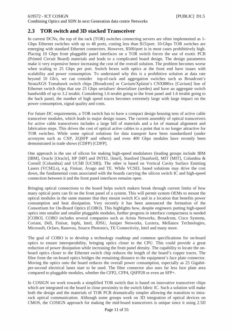
2.4 Novel Fibres enabling high data capacity interconnects The interconnects in data centres of today are typically electrical cables for distances up to around 10 m, while optical fibre cables are used for longer lengths, more specifically multi-mode (MM) optical fibre cables for lengths up to a few 100 m, and single mode fibre (SM) for distances above a few 100 m. Typical data rate is 10 Gb/s and wavelength is either 850nm (MM fibre cables) or 1310nm (SM fibre cables). The DCN market can be divided in two main categories. The first is medium/large enterprise with the number of servers in the 1000’s. Here DCN dimensions are such as a 100m reach covers about 80% of the total number of interconnections and a 200m reach covers 99% of lengths. Therefore MM fibres are by far the preferred solution in this industry sector, also due to cost considerations. The second category of datacentres is the hyper-scale enterprises with 100,000’s of servers. These hyper-scale enterprises are characterized by parallel processing algorithms for huge data sets using low cost servers and huge facilities requiring optical connections up to 500m, where 4-lane, parallel SMF (PSM4) is the standard interconnection cable. The MPO-terminated, high fibre-count trunk cables with MM or SM fibres are typical used for both markets and are available with 8, 12, 24 and 48 fibre connectors, Figure 1.
Figure 1: 8 fibre MPO-terminated cables (OFS)
Looking at industry requirement for the next few years, there is substantial interest for optical cabling interconnects, as they generally can deliver greater speeds & density at lower cost and provide the ability to support further upscaling of the size of the datacentres. Regarding higher speed, 100Gbit/s data centre switches are expected to come on the marked in 2016. Simultaneous huge advances in VCSEL transceivers for MM fibres are taking place in recent years, including the development of 100Gbit/s MM transceivers and extended reach MM transceivers. Multiple wavelengths (Coarse Wavelength Division Multiplexing, CWDM) on MM fibres is another trend, which is supported by development of MM fibres with wide bandwidth [OFC1, OFC2]. For the development of hyper-scale datacentres, parallel SM fibres is currently a good option, but it is clearly important to look at solutions to maintain system scalability for the years to come, which explain the strong interest from
619572 - ICT COSIGN [PUBLIC] D1.5 Combining Optics and SDN In next Generation data centre Networks
Page 13 of 55
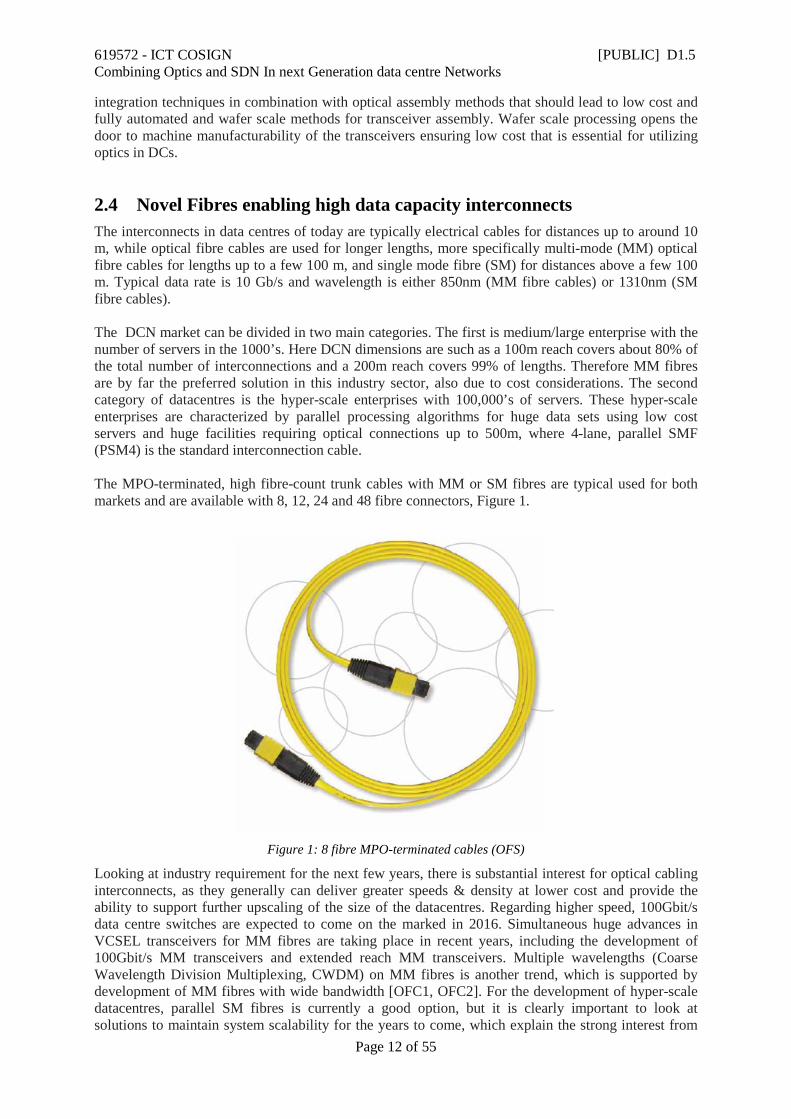
the DCN community in the latest development of telecom fibres enabling spatial division multiplexing (SDM). Existing pluggables for data rates above 10 Gb/s are shown in Table 1.
Table 1: Typical pluggable used for datacentres.
A confusing range of pluggables are observed. Besides the standard specified by the IEEE standard association, a number of alternative types has emerged. The existence of multiple solutions at this time and their adoption is very much cost driven. A good example is PSM4, which uses more fibres but requires fewer lasers in the transmission system and therefore is competitive in terms of price over LR4, for shorter reach interconnections. Looking at future developments, it is expected that the growth in size of DC’s will continue, dictating a migration of interconnect technologies to single mode optical fibres. It is anticipated that cost considerations may push the wavelength to the standard telecom waveband at 1.55µm, assuming suitable cost-effective solutions for transceiver technology are identified. As the interconnection length scales increase and DCN architectures evolve in order to accommodate the exponential growth in the number of servers, it is anticipated that the issue of identifying interconnect solutions that afford a much higher density of optical paths per cross sectional area will become progressively more important. COSIGN will respond to this future requirement by investigating the most advanced types of SDM-enabling transmission fibres, which will enable scaling up channel density and data rates in medium and long range connections. In the COSIGN programme we will investigate multicore fibres (MCFs) as well as few mode fibres (FMF). In parallel, we will investigate solutions to address another issue that is envisaged to emerge in the next few years: the objective of reducing the signal latency accumulated along the cables. Clearly interconnects based on conventional optical fibres will be able to offer a maximum speed largely dictated by the refractive index of the silica glass, however this is ~30% higher than, for instance, what a free-space line-of-sight line could achieve. The availability of a cable that can operate at the same signal latency would obviously represent a very substantial improvement over what is possible using conventional fibre technology. In COSIGN, we will also investigate hollow core bandgap fibres (HC-PBGFs), which enable signal speed of about 99.7% the speed of light in vacuum. Besides investigating in detail the advantages of these novel fibre technologies and developing bespoke fibres with properties tailored for DCN applications and demonstrators, COSIGN will also investigate the issue of interfacing such novel fibres to switches developed within the project.
619572 - ICT COSIGN [PUBLIC] D1.5 Combining Optics and SDN In next Generation data centre Networks
Page 14 of 55
2.5 High port count low latency optical network switches In this section, several optical switch technologies with different features are reviewed, which are potentially available for different DCN use cases.
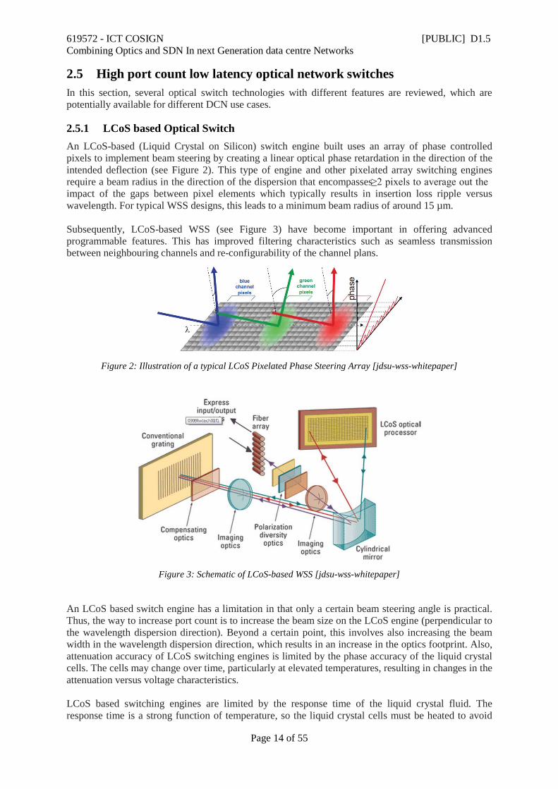
2.5.1 LCoS based Optical Switch An LCoS-based (Liquid Crystal on Silicon) switch engine built uses an array of phase controlled pixels to implement beam steering by creating a linear optical phase retardation in the direction of the intended deflection (see Figure 2). This type of engine and other pixelated array switching engines require a beam radius in the direction of the dispersion that encompasses ≥2 pixels to average out the impact of the gaps between pixel elements which typically results in insertion loss ripple versus wavelength. For typical WSS designs, this leads to a minimum beam radius of around 15 µm. Subsequently, LCoS-based WSS (see Figure 3) have become important in offering advanced programmable features. This has improved filtering characteristics such as seamless transmission between neighbouring channels and re-configurability of the channel plans.
Figure 2: Illustration of a typical LCoS Pixelated Phase Steering Array [jdsu-wss-whitepaper]
Figure 3: Schematic of LCoS-based WSS [jdsu-wss-whitepaper]
An LCoS based switch engine has a limitation in that only a certain beam steering angle is practical. Thus, the way to increase port count is to increase the beam size on the LCoS engine (perpendicular to the wavelength dispersion direction). Beyond a certain point, this involves also increasing the beam width in the wavelength dispersion direction, which results in an increase in the optics footprint. Also, attenuation accuracy of LCoS switching engines is limited by the phase accuracy of the liquid crystal cells. The cells may change over time, particularly at elevated temperatures, resulting in changes in the attenuation versus voltage characteristics. LCoS based switching engines are limited by the response time of the liquid crystal fluid. The response time is a strong function of temperature, so the liquid crystal cells must be heated to avoid
619572 - ICT COSIGN [PUBLIC] D1.5 Combining Optics and SDN In next Generation data centre Networks
Page 15 of 55
extremely slow response times at low temperatures. With a heater, response times can be tens of milliseconds. Multiple switching steps may be required to complete one switching operation however, particularly for LCoS where transitions must be carefully controlled to prevent crosstalk into unwanted ports during switching operations.
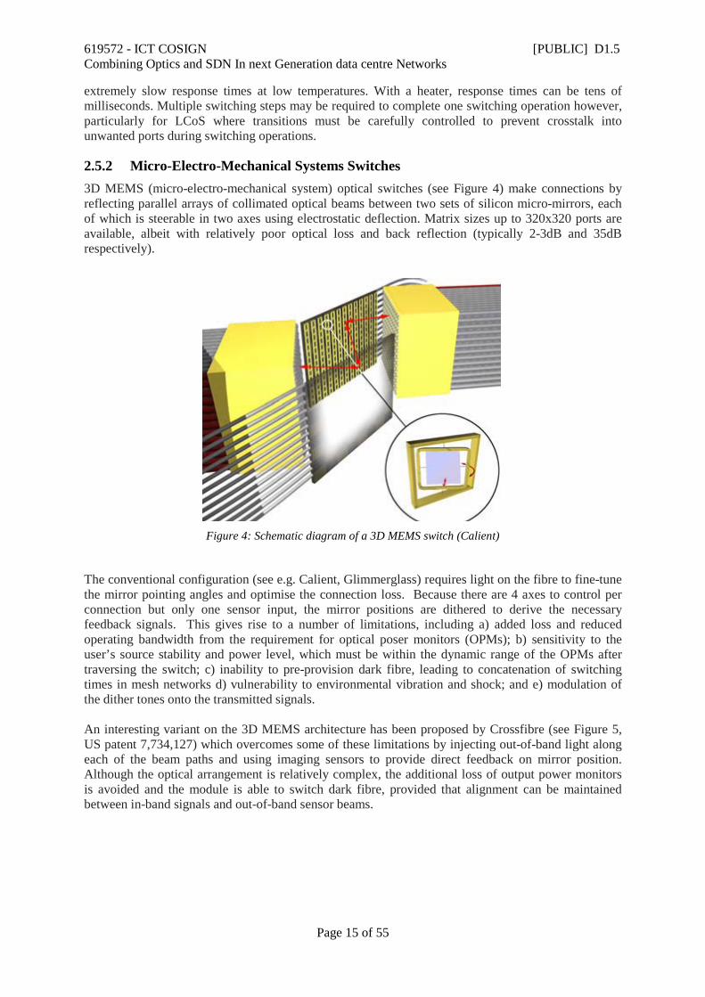
2.5.2 Micro-Electro-Mechanical Systems Switches 3D MEMS (micro-electro-mechanical system) optical switches (see Figure 4) make connections by reflecting parallel arrays of collimated optical beams between two sets of silicon micro-mirrors, each of which is steerable in two axes using electrostatic deflection. Matrix sizes up to 320x320 ports are available, albeit with relatively poor optical loss and back reflection (typically 2-3dB and 35dB respectively).
Figure 4: Schematic diagram of a 3D MEMS switch (Calient)
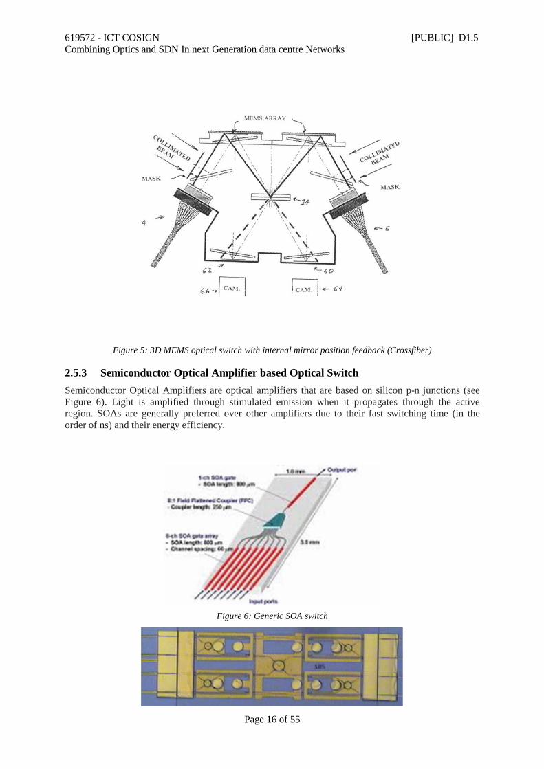
The conventional configuration (see e.g. Calient, Glimmerglass) requires light on the fibre to fine-tune the mirror pointing angles and optimise the connection loss. Because there are 4 axes to control per connection but only one sensor input, the mirror positions are dithered to derive the necessary feedback signals. This gives rise to a number of limitations, including a) added loss and reduced operating bandwidth from the requirement for optical poser monitors (OPMs); b) sensitivity to the user’s source stability and power level, which must be within the dynamic range of the OPMs after traversing the switch; c) inability to pre-provision dark fibre, leading to concatenation of switching times in mesh networks d) vulnerability to environmental vibration and shock; and e) modulation of the dither tones onto the transmitted signals. An interesting variant on the 3D MEMS architecture has been proposed by Crossfibre (see Figure 5, US patent 7,734,127) which overcomes some of these limitations by injecting out-of-band light along each of the beam paths and using imaging sensors to provide direct feedback on mirror position. Although the optical arrangement is relatively complex, the additional loss of output power monitors is avoided and the module is able to switch dark fibre, provided that alignment can be maintained between in-band signals and out-of-band sensor beams.
619572 - ICT COSIGN [PUBLIC] D1.5 Combining Optics and SDN In next Generation data centre Networks
Page 16 of 55
Figure 5: 3D MEMS optical switch with internal mirror position feedback (Crossfiber)
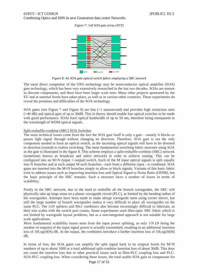
2.5.3 Semiconductor Optical Amplifier based Optical Switch Semiconductor Optical Amplifiers are optical amplifiers that are based on silicon p-n junctions (see Figure 6). Light is amplified through stimulated emission when it propagates through the active region. SOAs are generally preferred over other amplifiers due to their fast switching time (in the order of ns) and their energy efficiency.
Figure 6: Generic SOA switch
619572 - ICT COSIGN [PUBLIC] D1.5 Combining Optics and SDN In next Generation data centre Networks
Page 17 of 55
Figure 7: 1x8 SOA gate array (NTT)
Figure 8: An SOA gate optical switch fabric employing a SRC network
The most direct competitor of the OXS technology may be semiconductor optical amplifier (SOA) gate technology, which has been very extensively researched in the last two decades. SOAs are mature as discrete components, and there have been larger scale tests. Many other projects sponsored by the EU and at national levels have taken place, as well as in various other countries. These experiments do reveal the promises and difficulties of the SOA technology. SOA gates (see Figure 7 and Figure 8) are fast (~1 nanosecond) and provides high extinction ratio (>40 dB) and optical gain of up to 30dB. This in theory should enable fast optical switches to be made with good performance. SOAs have optical bandwidth of up to 50 nm, therefore being transparent to the wavelength of WDM optical signals. Split-reshuffle-combine (SRC) SOA Switches The main technical issues come from the fact the SOA gate itself is only a gate – namely it blocks or passes light signal through without changing its direction. Therefore, SOA gate is not the only component needed to form an optical switch, as the incoming optical signals will have to be diverted in direction (routed) to realize switching. The most fundamental switching fabric structure using SOA as the gate is illustrated in the figure 8. This scheme employs a split-reshuffle-combine (SRC) network (sometimes known as broadcast and select network) in order to achieve routing. This can be configured into an M×N (input × output) switch. Each of the M input optical signals is split equally into N branches and at each output M such branches - each from a different input - is combined. SOA gates are inserted into the M×N branches simply to allow or block signals. Variants of this basic fabric exist to address issues such as improving insertion loss and Optical Signal to Noise Ratio (OSNR), but the basic principle of the SRC remains. Such a structure faces a number of issues in terms of scalability. Firstly in the SRC network, due to the need to reshuffle all the branch waveguides, the SRC will physically take up large areas on a planar waveguide circuit (PLC), as limited by the bending radius of the waveguides. Attempts have been made to make abrupt waveguide turns using corner mirror, but still the large number of branch waveguides makes it very difficult to place all waveguides on the same PLC. The 1xN splitters and Mx1 combiners also become increasingly difficult to fabricate, as their size scales with the switch port counts. Some experiments used fibre-optic SRC fabric which is not limited by waveguide layout problems, but as a non-integrated approach is not suitable for large scale applications. More fundamental scalability issues stem from the input power splitting, as only 1/N (N being the number of outputs) of the input signal power is actually transmitted, resulting in an additional insertion loss of 10Log10(N) dB. At the output, the combiners introduce a further insertion loss of 10Log10(M) dB. In terms of loss, the SOA gates can amplify the split signal back to its original levels for M×N numbers of up to about 1000 or a total additional split-combine insertion loss of about 30dB. This does not count the insertion loss due to other practical issues such as fibre-PLC coupling loss and PLC-SOA-PLC coupling loss. When considering these losses, the total usable SOA gain to compensate for
619572 - ICT COSIGN [PUBLIC] D1.5 Combining Optics and SDN In next Generation data centre Networks
Page 18 of 55
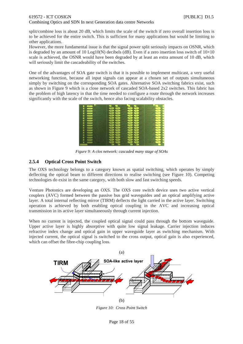
split/combine loss is about 20 dB, which limits the scale of the switch if zero overall insertion loss is to be achieved for the entire switch. This is sufficient for many applications but would be limiting to other applications. However, the more fundamental issue is that the signal power split seriously impacts on OSNR, which is degraded by an amount of 10 Log10(N) decibels (dB). Even if a zero insertion loss switch of 10×10 scale is achieved, the OSNR would have been degraded by at least an extra amount of 10 dB, which will seriously limit the cascadeability of the switches. One of the advantages of SOA gate switch is that it is possible to implement multicast, a very useful networking function, because all input signals can appear at a chosen set of outputs simultaneous simply by switching on the corresponding SOA gates. Alternative SOA switching fabrics exist, such as shown in Figure 9 which is a close network of cascaded SOA-based 2x2 switches. This fabric has the problem of high latency in that the time needed to configure a route through the network increases significantly with the scale of the switch, hence also facing scalability obstacles.
Figure 9: A clos network: cascaded many stage of SOAs
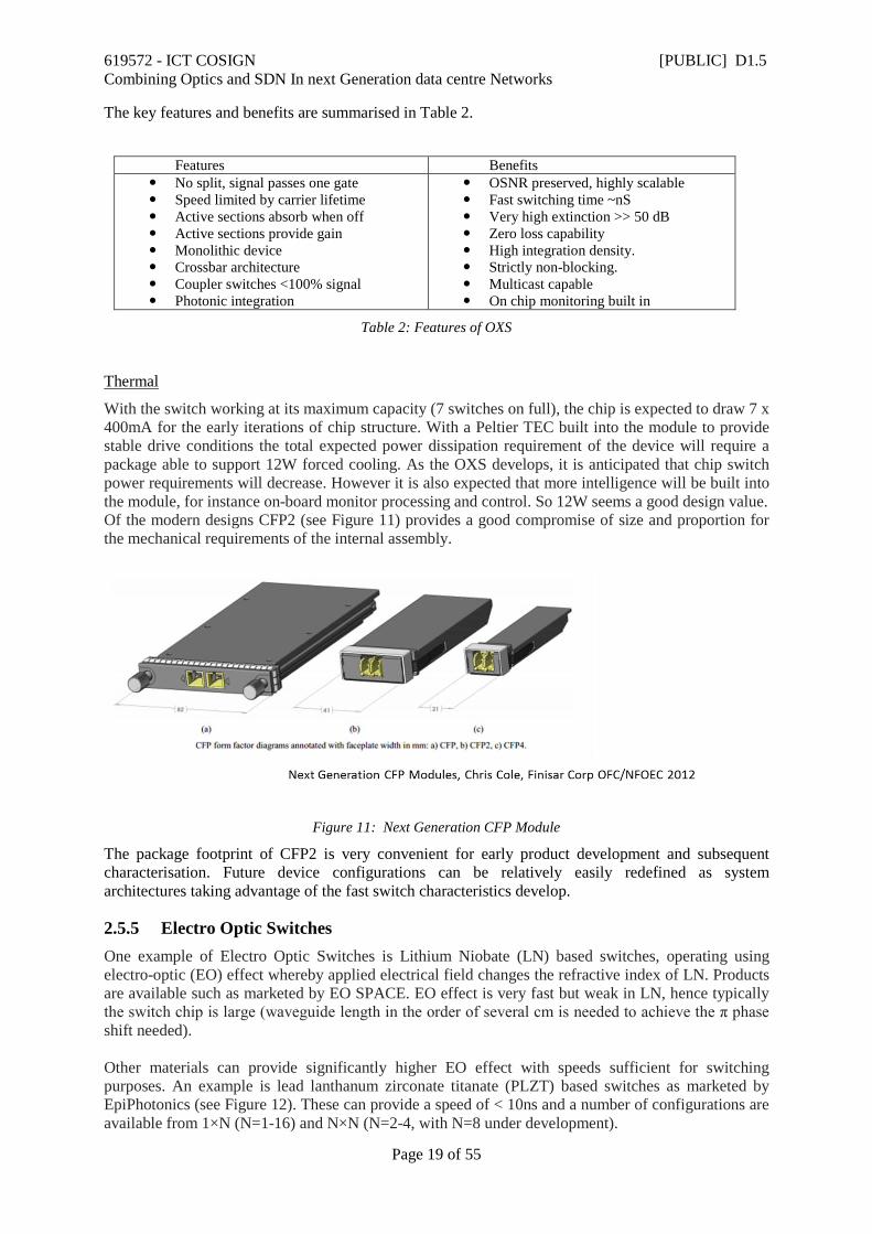
2.5.4 Optical Cross Point Switch The OXS technology belongs to a category known as spatial switching, which operates by simply deflecting the optical beam to different directions to realise switching (see Figure 10). Competing technologies do exist in the same category, with both slow and fast switching speeds. Venture Photonics are developing an OXS. The OXS core switch device uses two active vertical couplers (AVC) formed between the passive bus grid waveguides and an optical amplifying active layer. A total internal reflecting mirror (TIRM) deflects the light carried in the active layer. Switching operation is achieved by both enabling optical coupling in the AVC and increasing optical transmission in its active layer simultaneously through current injection. When no current is injected, the coupled optical signal could pass through the bottom waveguide. Upper active layer is highly absorptive with quite low signal leakage. Carrier injection induces refractive index change and optical gain in upper waveguide layer as switching mechanism. With injected current, the optical signal is switched to the cross output, optical gain is also experienced, which can offset the fibre-chip coupling loss.
(a)
(b)
Figure 10: Cross Point Switch
619572 - ICT COSIGN [PUBLIC] D1.5 Combining Optics and SDN In next Generation data centre Networks
Page 19 of 55
The key features and benefits are summarised in Table 2.
Features Benefits No split, signal passes one gate Speed limited by carrier lifetime Active sections absorb when off Active sections provide gain Monolithic device Crossbar architecture Coupler switches <100% signal Photonic integration
OSNR preserved, highly scalable Fast switching time ~nS Very high extinction >> 50 dB Zero loss capability High integration density. Strictly non-blocking. Multicast capable On chip monitoring built in
Table 2: Features of OXS
Thermal
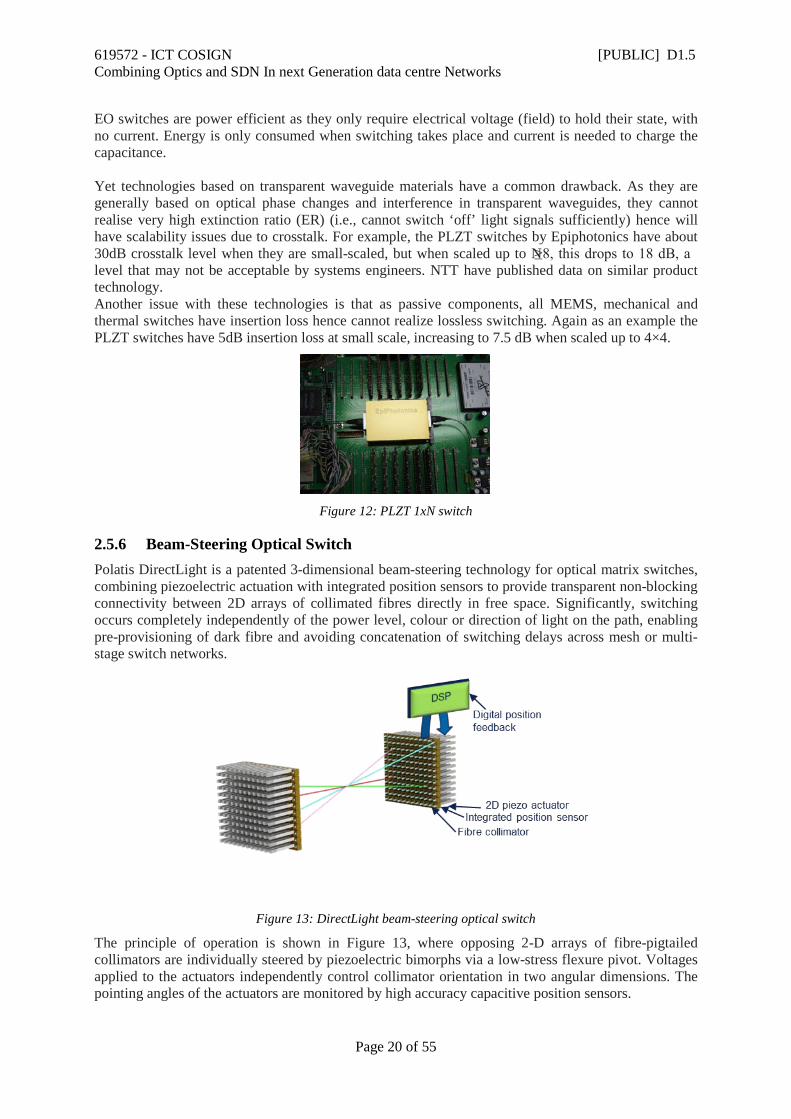
With the switch working at its maximum capacity (7 switches on full), the chip is expected to draw 7 x 400mA for the early iterations of chip structure. With a Peltier TEC built into the module to provide stable drive conditions the total expected power dissipation requirement of the device will require a package able to support 12W forced cooling. As the OXS develops, it is anticipated that chip switch power requirements will decrease. However it is also expected that more intelligence will be built into the module, for instance on-board monitor processing and control. So 12W seems a good design value. Of the modern designs CFP2 (see Figure 11) provides a good compromise of size and proportion for the mechanical requirements of the internal assembly.
Figure 11: Next Generation CFP Module
The package footprint of CFP2 is very convenient for early product development and subsequent characterisation. Future device configurations can be relatively easily redefined as system architectures taking advantage of the fast switch characteristics develop.
2.5.5 Electro Optic Switches One example of Electro Optic Switches is Lithium Niobate (LN) based switches, operating using electro-optic (EO) effect whereby applied electrical field changes the refractive index of LN. Products are available such as marketed by EO SPACE. EO effect is very fast but weak in LN, hence typically the switch chip is large (waveguide length in the order of several cm is needed to achieve the π phase shift needed). Other materials can provide significantly higher EO effect with speeds sufficient for switching purposes. An example is lead lanthanum zirconate titanate (PLZT) based switches as marketed by EpiPhotonics (see Figure 12). These can provide a speed of < 10ns and a number of configurations are available from 1×N (N=1-16) and N×N (N=2-4, with N=8 under development).
619572 - ICT COSIGN [PUBLIC] D1.5 Combining Optics and SDN In next Generation data centre Networks
Page 20 of 55
EO switches are power efficient as they only require electrical voltage (field) to hold their state, with no current. Energy is only consumed when switching takes place and current is needed to charge the capacitance. Yet technologies based on transparent waveguide materials have a common drawback. As they are generally based on optical phase changes and interference in transparent waveguides, they cannot realise very high extinction ratio (ER) (i.e., cannot switch ‘off’ light signals sufficiently) hence will have scalability issues due to crosstalk. For example, the PLZT switches by Epiphotonics have about 30dB crosstalk level when they are small-scaled, but when scaled up to N≥8, this drops to 18 dB, a level that may not be acceptable by systems engineers. NTT have published data on similar product technology. Another issue with these technologies is that as passive components, all MEMS, mechanical and thermal switches have insertion loss hence cannot realize lossless switching. Again as an example the PLZT switches have 5dB insertion loss at small scale, increasing to 7.5 dB when scaled up to 4×4.
Figure 12: PLZT 1xN switch
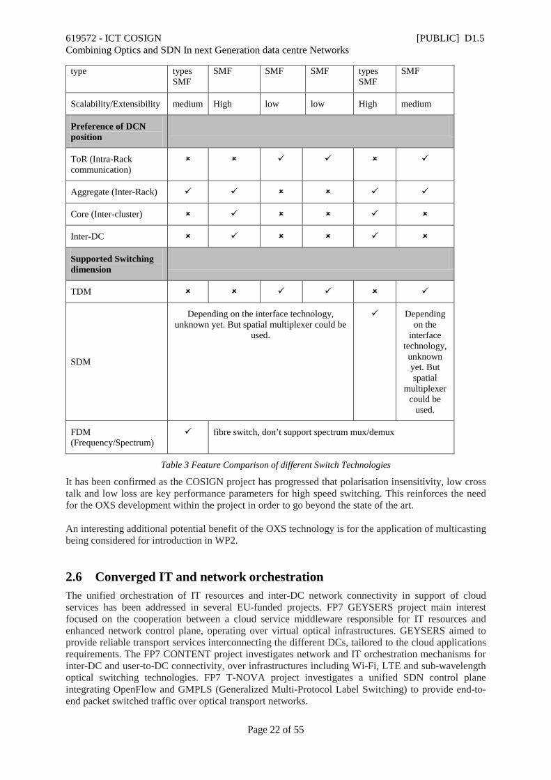
2.5.6 Beam-Steering Optical Switch Polatis DirectLight is a patented 3-dimensional beam-steering technology for optical matrix switches, combining piezoelectric actuation with integrated position sensors to provide transparent non-blocking connectivity between 2D arrays of collimated fibres directly in free space. Significantly, switching occurs completely independently of the power level, colour or direction of light on the path, enabling pre-provisioning of dark fibre and avoiding concatenation of switching delays across mesh or multi-stage switch networks.
Figure 13: DirectLight beam-steering optical switch
The principle of operation is shown in Figure 13, where opposing 2-D arrays of fibre-pigtailed collimators are individually steered by piezoelectric bimorphs via a low-stress flexure pivot. Voltages applied to the actuators independently control collimator orientation in two angular dimensions. The pointing angles of the actuators are monitored by high accuracy capacitive position sensors.

619572 - ICT COSIGN [PUBLIC] D1.5 Combining Optics and SDN In next Generation data centre Networks
Page 21 of 55
The arrays are built up in rows (or slices) of up to 12 fibre ports so that the matrix size can be configured for individual customer requirements, scaling (currently) from 4x4 to 192x192 fibres with consistent cost per port. During factory alignment, the optical switch elements are trained to find the optimum target positions for every path between ingress and egress ports. Target values are stored in memory and are used by a digital control loop to drive and hold the actuators in the correct position for each connection. Variable attenuation can be introduced on a connected path if required by controlled misalignment of one or more axes from the optimum target position. Because there are no micro-mirrors in the optical path, performance is limited only by the imperfections in the collimating lenses, which can be kept in perfect on-axis alignment using position feedback. Typical optical loss below 1dB is achieved routinely, with worst case back reflection and crosstalk significantly better than -50dB. Repeatability of connection loss is typically under 50mdB, with minimal polarisation or wavelength impairments. The main limitation is that, in common with other micro-mechanical devices, switching speeds are restricted to the 10-20ms range.
2.5.7 Comparison Analysis and summary As a summary, Table 3 depicts the feature comparison of the above mentioned switching technologies in terms of defined figure of merits, preference of DCN position and supported switch dimension. It is worth noting that the requirements of switches varies with their DCN position. Specifically, TDM based connections (including Optical TDM and OPS/OBS) are more suitable to support intra-rack short-term and bursty traffic, which need ns optical switch to implement fast reconfiguration while power efficiency is less important. Also, considering the better scalability (which is helpful to extend the support to more servers) of optical cross point technology, it is more suitable than SOA and electro based optic switch to fit in this position. Regarding to the inter-rack and inter-cluster interconnection, switch scalability is a big concern to construct a flattened structure (especially for the inter-cluster communication). So, beam steering and MEMS based switches are more preferred, while beam steering needs fewer reconfiguration time. And also SDM based interconnection technology could facilitate the wiring engineering and improve the port density of switch.
Figure of Merits
Technology
LCoS MEMS SOA Electro Optic
Switches
Beam Steering
Optical Cross Point
Power efficiency Low Medium Low High Low (0.1)
Medium
Reconfiguration time >100ms 10-200ms ns ns 25ms ns
Switch delay <100ps <100ps <100ps <100ps 20 ps <100ps
Insertion loss (db)
High (typical 7)
Medium (2 db for 1×2, increase with the switch dimension)
Low/zero high 1.0 Low/zero
Supported connector All All types All types All types All All types
619572 - ICT COSIGN [PUBLIC] D1.5 Combining Optics and SDN In next Generation data centre Networks
Page 22 of 55
type types SMF
SMF SMF SMF types SMF
SMF
Scalability/Extensibility medium High low low High medium
Preference of DCN position
ToR (Intra-Rack communication)
Aggregate (Inter-Rack)
Core (Inter-cluster)
Inter-DC
Supported Switching dimension
TDM
SDM
Depending on the interface technology, unknown yet. But spatial multiplexer could be
used.
Depending on the
interface technology, unknown yet. But spatial
multiplexer could be
used.
FDM (Frequency/Spectrum)
fibre switch, don’t support spectrum mux/demux
Table 3 Feature Comparison of different Switch Technologies
It has been confirmed as the COSIGN project has progressed that polarisation insensitivity, low cross talk and low loss are key performance parameters for high speed switching. This reinforces the need for the OXS development within the project in order to go beyond the state of the art. An interesting additional potential benefit of the OXS technology is for the application of multicasting being considered for introduction in WP2.
2.6 Converged IT and network orchestration The unified orchestration of IT resources and inter-DC network connectivity in support of cloud services has been addressed in several EU-funded projects. FP7 GEYSERS project main interest focused on the cooperation between a cloud service middleware responsible for IT resources and enhanced network control plane, operating over virtual optical infrastructures. GEYSERS aimed to provide reliable transport services interconnecting the different DCs, tailored to the cloud applications requirements. The FP7 CONTENT project investigates network and IT orchestration mechanisms for inter-DC and user-to-DC connectivity, over infrastructures including Wi-Fi, LTE and sub-wavelength optical switching technologies. FP7 T-NOVA project investigates a unified SDN control plane integrating OpenFlow and GMPLS (Generalized Multi-Protocol Label Switching) to provide end-to-end packet switched traffic over optical transport networks.
619572 - ICT COSIGN [PUBLIC] D1.5 Combining Optics and SDN In next Generation data centre Networks
Page 23 of 55
The fully automated, on-demand allocation of intra-DC network resources along with the entire cloud service life-cycle, including provisioning, upgrading, downgrading and deletion is still an open challenge. The IETF is working on GMPLS for core transport such as Optical Transport Networks (OTN) or Wavelength Switched Optical Networks (WSON) where the basic support of OpenFlow for circuit switched networks is defined. Initial OpenFlow protocol extensions for optical networks were presented and currently being developed by the Optical Transport Working group of the ONF. The COSIGN approach solution aims to automate the provisioning and configuration of the intra-DC network, computing and storage resources. The orchestrator in COSIGN manages the entire set of resources as a unified entity characterized by automated elastic rules and IT/network resources interdependencies. The orchestrator coordinates the configuration of the DC network according to the dynamicity of cloud services along with their lifecycle, supporting intra-DC VMs migration and traffic handling between VMs. The orchestrator manages the novel optical TOR switches of the DC network which are the main focus of COSIGN project; thanks to an SDN controller that interacts with the underlying DC infrastructure and exposes a logical, abstracted, vendor independent view of the network resources towards the management platform. The innovative optical technologies developed in WP2 specific for the DC environments represent the novelty and a challenge for the SDN controller. The characteristics and capabilities of the optical technologies have been analysed and abstracted. The key functional aspects and protocols required are being built for the communications between the SDN controller and optical devices.
2.7 Virtualization technologies ICT infrastructures, especially data centres (DCs), are becoming increasingly complex, mainly due to their large scale and the growth of the services and applications that they have to handle. This puts a great pressure on infrastructure owners, which are continuously forced to deliver resources faster, support new business initiatives and keep pace with the competition. In order to handle such demands, a highly flexible, dynamic and resilient infrastructure is a must. Additionally, such an infrastructure has to be easily manageable and scalable so as to cope with unexpected and ever-changing workload profiles inside the DC. Virtualization technologies, in particular server virtualization, are seen as a very promising solution to overcome these challenges. In fact, according to the Gartner Group [Gartner], virtualization has reached around 75% of worldwide server workloads in 2014 and is predicted to reach around 86% in 2018. The main reason on why virtualization is being adopted so massively inside DCs is due to the benefits it offers, such as improved availability and disaster recovery, higher flexibility and increased server utilization. Moreover, the emergence of the Software Defined Infrastructure (SDI) paradigm has spurred the adoption of virtualization techniques in all aspects of the DC, extending virtualization beyond compute to network and storage, leading to the so called Software Defined Data Centre (SDDC). Some IT companies are starting to offer cloud services based on the concept of SDDC, leveraging the benefits of virtualization from individual servers to whole infrastructures encompassing both IT resources and network capabilities, such as VMware [VMW1]. Furthermore, DC infrastructures are increasingly transforming to multi-tenant hosting of heterogeneous types of tenants by adopting a service model in which each tenant is provided with its own virtual infrastructure. In such an environment network virtualization (NV) becomes very important and, combined with IT virtualization, allows the DC operator to create multiple co-existing but isolated infrastructures for their tenants. Looking at the maturity of virtualization techniques, server virtualization is the most mature, spanning several commercial products from consolidated companies, such as VMware [VMW2], Citrix [Citrix] or Oracle [Oracle2]. For this, they are utilized worldwide in a large number of DCs and companies. On the other hand, NV techniques still are not mature enough. Hence, there have been huge research
619572 - ICT COSIGN [PUBLIC] D1.5 Combining Optics and SDN In next Generation data centre Networks
Page 24 of 55
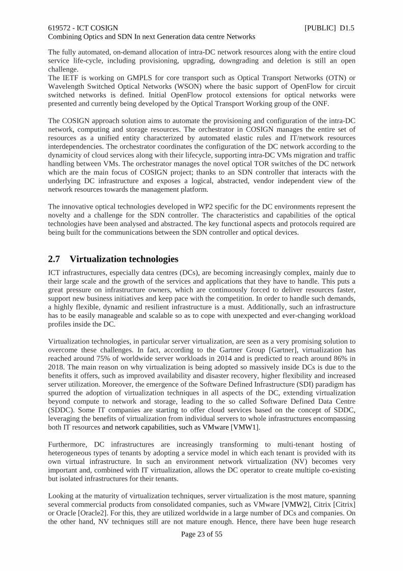
efforts on the field and several virtualization products have emerged during the past years, as presented in deliverable D1.3 [D1.3]. However, besides the increase of commercial and open source products that bring virtualization to networks, adequate virtualization of network resources, which takes full advantage of the underlying physical technology, is still not ready. Nevertheless, while comparing the adoption in the industry of NV solutions with respect to others in past years, it can be noted that, although still in development, NV solutions have become mainstream during 2014, and its utilization will continue to grow on the future, as stated in a report from SDx Central [SDxC]. In particular, looking at Figure 14, which represents the share of participants in a poll about NV adoption done by SDx Central, it can be seen that a large share of the respondents corresponds to industry, assessing that NV has become mainstream.
Figure 14. Share of respondents by type in a survey about NV adoption. Courtesy of [SDxC].
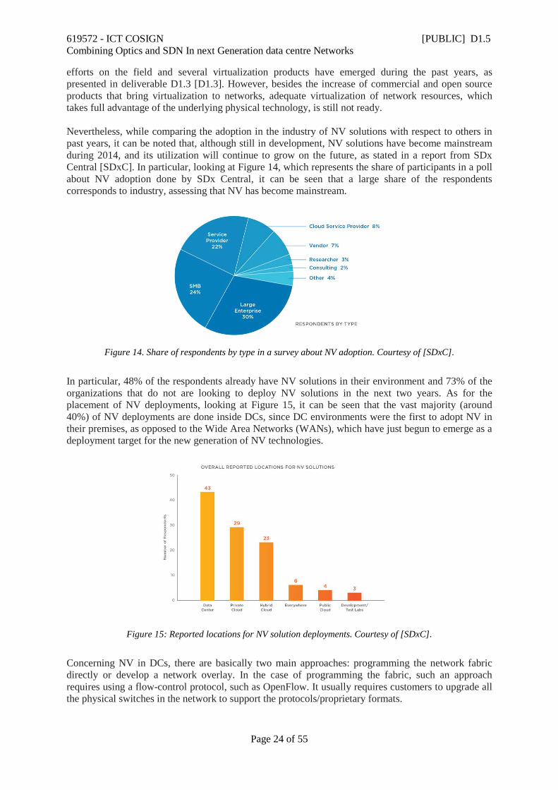
In particular, 48% of the respondents already have NV solutions in their environment and 73% of the organizations that do not are looking to deploy NV solutions in the next two years. As for the placement of NV deployments, looking at Figure 15, it can be seen that the vast majority (around 40%) of NV deployments are done inside DCs, since DC environments were the first to adopt NV in their premises, as opposed to the Wide Area Networks (WANs), which have just begun to emerge as a deployment target for the new generation of NV technologies.
Figure 15: Reported locations for NV solution deployments. Courtesy of [SDxC].
Concerning NV in DCs, there are basically two main approaches: programming the network fabric directly or develop a network overlay. In the case of programming the fabric, such an approach requires using a flow-control protocol, such as OpenFlow. It usually requires customers to upgrade all the physical switches in the network to support the protocols/proprietary formats.
619572 - ICT COSIGN [PUBLIC] D1.5 Combining Optics and SDN In next Generation data centre Networks
Page 25 of 55
On the other hand, the overlay approach is based on encapsulating the traffic between two end-points in the network thanks to proper encapsulation protocols. Next, this traffic is tunnelled through the network fabric. Over the past few years, there have been more vendors focusing on the overlay approach, primarily because it does not require any upgrade to the underlying network hardware. However, the recent research trends are focused on combining both approaches in order to reap the benefits that a hybrid approach can provide. In fact, commercial products based on a hybrid approach, such as Dynamic Virtual Networks – Data Centre (DVNd) from CPLANE NETWORKS [Planet] are starting to emerge. In COSIGN, we aim at the converged virtualization of IT and network resources. For this, COSIGN NV will follow a hybrid approach, such as that stated previously, mixing the direct programming of the network fabric, through proper extensions of the OpenFlow protocol, and the utilization of an overlay approach, harnessing the capabilities of the OpenStack Neutron project. Both COSIGN approaches to NV will be realized with the help of Software-defined Networking (SDN) principles. Due to the growing trend of bringing optical technologies inside the DC, there is an increasing need to develop proper virtualization solutions for optical networks. Compared to virtualization techniques in L2/L3 networks, the appliance of virtualization to optical devices is far more complex due to the nature of the optical medium and the specific technology adopted by the underlying network. Hence, huge research efforts are being dedicated on the development of the necessary technologies and tools to bring virtualization to optical networks as a whole. For instance, the latest OpenFlow specification 1.4, published in October 2013, is the first version to include extensions for optical networking. They include a way to declare (or detect) that a port is optical. Additionally, OpenFlow 1.4 also lets the controller know the power being transmitted and received at an optical port, a concern that just does not exist in Ethernet networks. However, beyond these points, OpenFlow, and other virtualization environment and protocols, are still lacking functionalities in order to be applied at production environments in optical networks as a whole. Nevertheless, there is some advancement in the industry in this regard. For instance, on 10th March 2015, Infinera announced that Pacnet has successfully deployed Infinera’s Open Transport Switch (OTS) within its SDN platform, Pacnet Enabled Network (PEN), across the most extensive, solely-owned 100 gigabits per second (Gb/s) enabled trans-Pacific and intra-Asia submarine network in the Asia-Pacific region [Infinera]. Such advancements signpost that the adoption of virtualization in optical networks is gaining strength and will be fully realized in the near future. In COSIGN, we are adopting heterogeneous advanced optical network technologies including both switching and transport technologies. Therefore, it is challenging to design and develop proper virtualization mechanisms for such optical data plane. The features of each technology need to be investigated carefully to fully explore its advantage while virtualizing it. Meanwhile, the unique optical layer constraints (e.g. wavelength/spectrum continuity and impairments) need to be taken into account when composing virtual optical slices over these technologies. The optical NV should also be coordinated with the IT virtualization (compute and storage). The seamless integration of the optical NV and the IT virtualization will become a key highlight of the COSIGN project.

619572 - ICT COSIGN [PUBLIC] D1.5 Combining Optics and SDN In next Generation data centre Networks
Page 26 of 55
3 COSIGN solutions evaluated against existing solutions In this section, the COSIGN solution is evaluated and benchmarked against other Optical DCN solutions. Six different solutions have been identified, which all have received significant attention in the industrial and/or the research community, namely: Calient [Calient], Helios [Helios], Plexxi [Plexi], MIMO OFDM [ofdm-dcn-2012], Data Vortex [dv-mcn-2007] and Petabit [petabit-2010]. The proposals are benchmarked to the COSIGN approach in terms of the following network properties: high radix TOR switch with optical interconnects, SDM based fibres, optical fast switching (ns), large scale optical switch, SDN control, path computation and network service virtualization.
3.1 Calient Calient provides a number of different solutions targeting the Data Centre applications; e.g. the LightConnect Fabric Virtual Pod Data Centres, Multi-Tenant Data Centres and Software defined Packet Optical Datacenter networks. The virtual Pod is a new concept to improve server and storage utilization rates in data centres. It achieves this by allowing Pod resources to be flexibly shared and reassigned at the optical layer in response to the needs of workloads. Calients Multi-Tenant data centre approach uses optical circuit switching to replace manual optical fibre connectivity and patching typically deployed in datacentre hosting facilities. For comparison with the COSIGN approach, the most interesting concept from Calient is the Software defined Packet Optical Datacenter Network shown in Figure 16.
Figure 16: Calient Software defined packet-optical datacenter networks[Calient].
In the Calient architecture, a smaller packet-based network handling short non-persistent data flows interconnects all top of rack switches in the data centre or cluster. This is complimented by a circuit switched fabric consisting of one or more optical circuit switches such as CALIENT’s S320. This allows for a direct optical path to be established e.g. in the case of a large (Elephant) flow opens between distinct ToRs. Furthermore, this allows according to Calient “unconstrained data flow

619572 - ICT COSIGN [PUBLIC] D1.5 Combining Optics and SDN In next Generation data centre Networks
Page 27 of 55
between the TOR uplinks with the absolute lowest latency possible (<60 ns)”. The circuit switched path can be maintained for as long as the high-capacity flow persists. Similar activity can be supported between multiple TORs simultaneously due to the high port density of circuit switches such as the S320. Calient provides OpenFlow API’s on the optical switches, e.g. S320, and the Calient software defined packet-optical data centre network will support an SDN infrastructure layer with coordinated control from the upper layers.
3.2 Helios Figure 17 shows a small example of the Helios architecture. Helios is a 2-level FatTree of pod switches and core switches. Core switches can be either electrical packet switches or optical circuit switches; the strengths of one type of switch are intended to compensate for the weaknesses of the other type. The circuit-switched portion handles baseline, slowly changing inter-pod communication. The packet-switched portion delivers all-to-all bandwidth for the bursty portion of inter-pod communication. The optimal mix is a trade-off of cost, power consumption, complexity, and performance for a given set of workloads. [Helios]
Figure 17: Helios DCN with Pod Switches and Core switches [Helios]
In Figure 17, each pod has a number of hosts (labelled “H”) connected to the pod switch by short copper links. The pod switch contains a number of optical transceivers (labelled “T”) to connect to the core switching array. In this example [ref H], half of the uplinks from each pod are connected to packet switches, each of which also requires an optical transceiver. The other half of uplinks from each pod switch pass through a passive optical multiplexer (labelled “M”) before connecting to a single optical circuit switch. These are called superlinks, and in this example they carry 20G of capacity (w = 2 wavelengths). The size of a superlink (w) is bounded by the number of WDM wavelengths supported by the underlying technology [Helios]. Helios is merely a research proposal and not product as in the case of Calient and Plexxi, which means that not all properties are addressed by the Helios proposal.
619572 - ICT COSIGN [PUBLIC] D1.5 Combining Optics and SDN In next Generation data centre Networks
Page 28 of 55
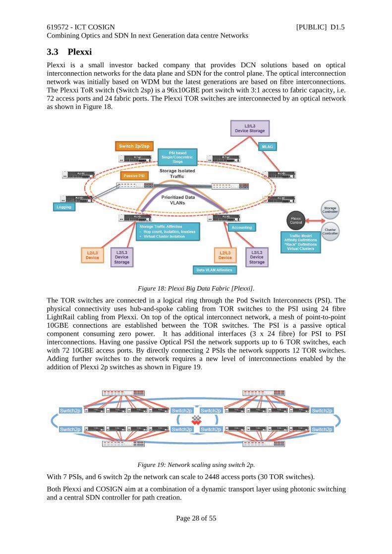
3.3 Plexxi Plexxi is a small investor backed company that provides DCN solutions based on optical interconnection networks for the data plane and SDN for the control plane. The optical interconnection network was initially based on WDM but the latest generations are based on fibre interconnections. The Plexxi ToR switch (Switch 2sp) is a 96x10GBE port switch with 3:1 access to fabric capacity, i.e. 72 access ports and 24 fabric ports. The Plexxi TOR switches are interconnected by an optical network as shown in Figure 18.
Figure 18: Plexxi Big Data Fabric [Plexxi].
The TOR switches are connected in a logical ring through the Pod Switch Interconnects (PSI). The physical connectivity uses hub-and-spoke cabling from TOR switches to the PSI using 24 fibre LightRail cabling from Plexxi. On top of the optical interconnect network, a mesh of point-to-point 10GBE connections are established between the TOR switches. The PSI is a passive optical component consuming zero power. It has additional interfaces (3 x 24 fibre) for PSI to PSI interconnections. Having one passive Optical PSI the network supports up to 6 TOR switches, each with 72 10GBE access ports. By directly connecting 2 PSIs the network supports 12 TOR switches. Adding further switches to the network requires a new level of interconnections enabled by the addition of Plexxi 2p switches as shown in Figure 19.
Figure 19: Network scaling using switch 2p.
With 7 PSIs, and 6 switch 2p the network can scale to 2448 access ports (30 TOR switches).
Both Plexxi and COSIGN aim at a combination of a dynamic transport layer using photonic switching and a central SDN controller for path creation.
619572 - ICT COSIGN [PUBLIC] D1.5 Combining Optics and SDN In next Generation data centre Networks
Page 29 of 55
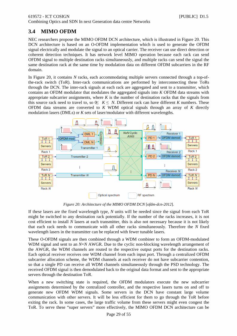
3.4 MIMO OFDM NEC researchers propose the MIMO OFDM DCN architecture, which is illustrated in Figure 20. This DCN architecture is based on an O-OFDM implementation which is used to generate the OFDM signal electrically and modulate the signal to an optical carrier. The receiver can use direct detection or coherent detection techniques. It has network level MIMO operation because each rack can send OFDM signal to multiple destination racks simultaneously, and multiple racks can send the signal the same destination rack at the same time by modulation data on different OFDM subcarriers in the RF domain.
In Figure 20, it contains N racks, each accommodating multiple servers connected through a top-of-the-rack switch (ToR). Inter-rack communications are performed by interconnecting these ToRs through the DCN. The inter-rack signals at each rack are aggregated and sent to a transmitter, which contains an OFDM modulator that modulates the aggregated signals into K OFDM data streams with appropriate subcarrier assignments, where K is the number of destination racks that the signals from this source rack need to travel to, so 0 ≤ K ≤ N. Different rack can have different K numbers. These OFDM data streams are converted to K WDM optical signals through an array of K directly modulation lasers (DMLs) or K sets of laser/modulator with different wavelengths.
Figure 20: Architecture of the MIMO OFDM DCN [ofdm-dcn-2012].
If these lasers are the fixed wavelength type, N units will be needed since the signal from each ToR might be switched to any destination rack potentially. If the number of the racks increases, it is not cost efficient to install N lasers at each transmitter, this is also not necessary because it is not likely that each rack needs to communicate with all other racks simultaneously. Therefore the N fixed wavelength lasers in the transmitter can be replaced with fewer tunable lasers.
These O-OFDM signals are then combined through a WDM combiner to form an OFDM-modulated WDM signal and sent to an N×N AWGR. Due to the cyclic non-blocking wavelength arrangement of the AWGR, the WDM channels are routed to the respective output ports for the destination racks. Each optical receiver receives one WDM channel from each input port. Through a centralized OFDM subcarrier allocation scheme, the WDM channels at each receiver do not have subcarrier contention, so that a single PD can receive all WDM channels simultaneously through the PSD technology. The received OFDM signal is then demodulated back to the original data format and sent to the appropriate servers through the destination ToR.
When a new switching state is required, the OFDM modulators execute the new subcarrier assignments determined by the centralized controller, and the respective lasers turns on and off to generate new OFDM WDM signals. Some servers in the DCN have constant large volume communication with other servers. It will be less efficient for them to go through the ToR before exiting the rack. In some cases, the large traffic volume from these servers might even congest the ToR. To serve these “super servers” more effectively, the MIMO OFDM DCN architecture can be
619572 - ICT COSIGN [PUBLIC] D1.5 Combining Optics and SDN In next Generation data centre Networks
Page 30 of 55
extended to reserve dedicated OFDM WDM transmitters and dedicated AWGR ports for them. These servers can bypass the ToR and connect to the transmitters directly.
3.5 Data Vortex
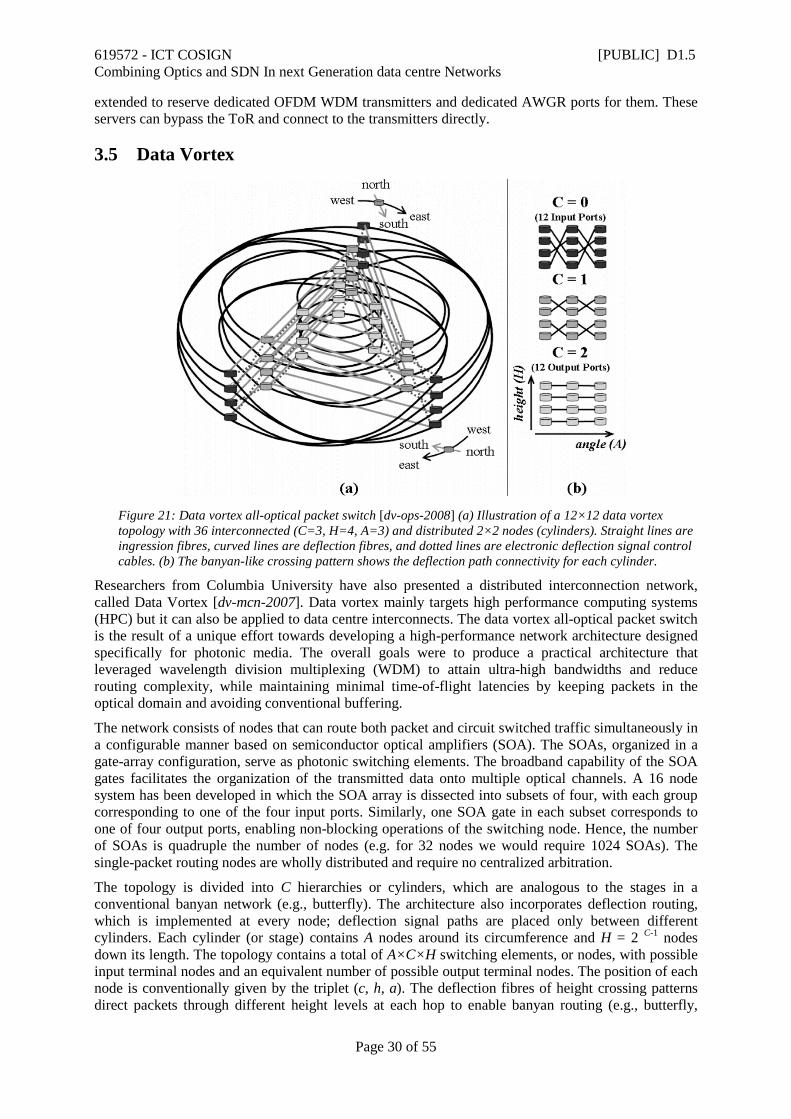
Figure 21: Data vortex all-optical packet switch [dv-ops-2008] (a) Illustration of a 12×12 data vortex topology with 36 interconnected (C=3, H=4, A=3) and distributed 2×2 nodes (cylinders). Straight lines are ingression fibres, curved lines are deflection fibres, and dotted lines are electronic deflection signal control cables. (b) The banyan-like crossing pattern shows the deflection path connectivity for each cylinder.
Researchers from Columbia University have also presented a distributed interconnection network, called Data Vortex [dv-mcn-2007]. Data vortex mainly targets high performance computing systems (HPC) but it can also be applied to data centre interconnects. The data vortex all-optical packet switch is the result of a unique effort towards developing a high-performance network architecture designed specifically for photonic media. The overall goals were to produce a practical architecture that leveraged wavelength division multiplexing (WDM) to attain ultra-high bandwidths and reduce routing complexity, while maintaining minimal time-of-flight latencies by keeping packets in the optical domain and avoiding conventional buffering.
The network consists of nodes that can route both packet and circuit switched traffic simultaneously in a configurable manner based on semiconductor optical amplifiers (SOA). The SOAs, organized in a gate-array configuration, serve as photonic switching elements. The broadband capability of the SOA gates facilitates the organization of the transmitted data onto multiple optical channels. A 16 node system has been developed in which the SOA array is dissected into subsets of four, with each group corresponding to one of the four input ports. Similarly, one SOA gate in each subset corresponds to one of four output ports, enabling non-blocking operations of the switching node. Hence, the number of SOAs is quadruple the number of nodes (e.g. for 32 nodes we would require 1024 SOAs). The single-packet routing nodes are wholly distributed and require no centralized arbitration.
The topology is divided into C hierarchies or cylinders, which are analogous to the stages in a conventional banyan network (e.g., butterfly). The architecture also incorporates deflection routing, which is implemented at every node; deflection signal paths are placed only between different cylinders. Each cylinder (or stage) contains A nodes around its circumference and H = 2 C-1 nodes down its length. The topology contains a total of A×C×H switching elements, or nodes, with possible input terminal nodes and an equivalent number of possible output terminal nodes. The position of each node is conventionally given by the triplet (c, h, a). The deflection fibres of height crossing patterns direct packets through different height levels at each hop to enable banyan routing (e.g., butterfly,

619572 - ICT COSIGN [PUBLIC] D1.5 Combining Optics and SDN In next Generation data centre Networks
Page 31 of 55
omega) to a desired height, and assist in balancing the load throughout the system, mitigating local congestion.
The data vortex topology exhibits a modular architecture therefore it can be scaled efficiently to large number of nodes. The main drawback of the data vortex architecture is that the banyan multiple-stage scheme becomes extremely complex when it is scaled to large networks. As the number of nodes increase, the packets have to traverse several nodes before reaching the destination address causing increased and nondeterministic latency.
3.6 Petabit
Figure 22: Petabit Switch [petabit-2010]
The architecture of Petabit is illustrated in Figure 22 and it adopts a three-stage Clos network. The servers are connected to the giant switch without any intermediate packet processing. Wavelength division multiplexing (WDM) is used to facilitate wiring between server racks and the switch. The switch fabric includes input modules (IMs), central modules (CMs), and output modules (OMs). Each IM/CM/OM includes an AWGR as the switch fabric. The only difference among these modules is that each input port of the CMs and OMs has a TWC that can be used to control the routing path. The IMs do not need TWCs because the wavelength at their input ports can be adjusted by controlling the tunable laser source on the line cards.
The Clos-based switch fabric has good scalability. If we use identical M × M AWGRs, the size of the switch is scaled to M 2 × M 2. Currently 128 × 128 AWGRs are available [ols-2004], so it is feasible to reach our target at 10,000 ports. Building an optical switch fabric also helps to reduce the power consumption compared to electrical designs of the same throughput. It is worth noting that other fast reconfigurable optical switch modules can be used to substitute the AWGRs in this architecture with minor modifications of the scheduling algorithm.
A prominent feature of this architecture compared to other architectures is that Petabit switch does not use any buffers inside the switch fabric (thus avoiding the power hungry E/O and O/E conversion). Instead, the congestion management is performed using electronic buffers in the Line cards and an efficient scheduling algorithm, which helps to reduce implementation complexity and to achieve low latency. Each line card that is connected to the input port of the Petabit switch hosts a buffer in which the packet are stored before the transmission. The packets are classified to different virtual output queues (VOQ) based on the destination address. Given the high number of ports, a VOQ is maintained per OM (the last stage of the switch fabric) instead of one VOQ per output port. Using one VOQ per OM simplifies the scheduling algorithm and the buffer management but on the other hand it introduces Head-of-line blocking (HOL). However, using an efficient scheduling algorithm and some speedup, the Petabit switch fabric can achieve up to 99.6% throughput even in the case of 10000 ports. The most important advantage of this architecture is that the average latency is only twice of a frame duration (200 ns) even at 80% load using three iteration of the scheduling algorithm. Hence, in contrast to the current data centre networks based on commodity switches, the latency is significantly reduced and almost independent of the switch size.

619572 - ICT COSIGN [PUBLIC] D1.5 Combining Optics and SDN In next Generation data centre Networks
Page 32 of 55
3.7 COSIGN comparison summary As a summary, Table 4 and Table 5 depict the feature comparison of the above mentioned optical DCN technologies in terms of data plane HW employed (Table 4) and Control plane functions supported (Table 5). In Table 4, the optical DCN technologies are benchmarked to the COSIGN approach in terms of the following network properties: high radix TOR switch with optical interconnects, SDM based fibres, optical fast switching (ns), large scale optical switch. In Table 5, the optical DCN technologies are benchmarked to the COSIGN approach in terms of the following network properties: SDN control, path computation and network service virtualization. There is a huge interest in Optical DCN’s, both academically and commercially. COSIGN is believed, based on the comparison study performed here, to provide a real enhancement of the state of the art in many of the compared areas. Moreover, it also defines a quite complete concept covering all aspects from orchestration, virtualization, and state of the art optical data plane technologies.
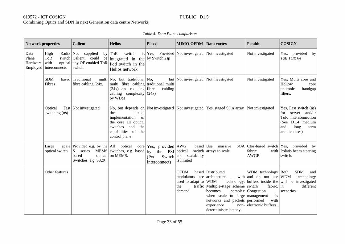
619572 - ICT COSIGN [PUBLIC] D1.5 Combining Optics and SDN In next Generation data centre Networks
Page 33 of 55
Table 4: Data Plane comparison
Network properties Calient Helios Plexxi MIMO-OFDM Data vortex Petabit COSIGN
Data Plane Hardware Employed
High Radix ToR switch with optical interconnects
Not supplied by Calient, could be any OF enabled ToR switch.
ToR switch is integrated in the Pod switch in the Helios network
Yes, Provided by Switch 2sp
Not investigated Not investigated Not investigated Yes, provided by TuE TOR 64
SDM based Fibres
Traditional multi fibre cabling (24x)
No, but traditional multi fibre cabling (24x) and reducing cabling complexity by WDM
No, but traditional multi fibre cabling (24x)
Not investigated Not investigated Not investigated Yes, Multi core and Hollow core photonic bandgap filters.
Optical Fast switching (ns)
Not investigated No, but depends on the actual implementation of the core all optical switches and the capabilities of the control plane
Not investigated Not investigated Yes, staged SOA array Not investigated Yes, Fast switch (ns) for server and/or ToR interconnection (See D1.4 medium and long term architectures)
Large scale optical switch
Provided e.g. by the S series MEMS based optical Switches, e.g. S320
All optical core switches, e.g. based on MEMS.
Yes, provided by the PSI (Pod Switch Interconnect)
AWG based optical switch and scalability is limited
Use massive SOA arrays to scale
Clos-based switch fabric with AWGR
Yes, provided by Polatis beam steering switch.
Other features OFDM based modulators are used to adapt to the traffic demand
Distributed architecture with WDM technology. Multiple-stage scheme becomes complex when scale to large networks and packets experience non- deterministic latency.
WDM technology and do not use buffers inside the switch fabric. Congestion management is performed with electronic buffers.
Both SDM and WDM technology will be investigated in different scenarios.
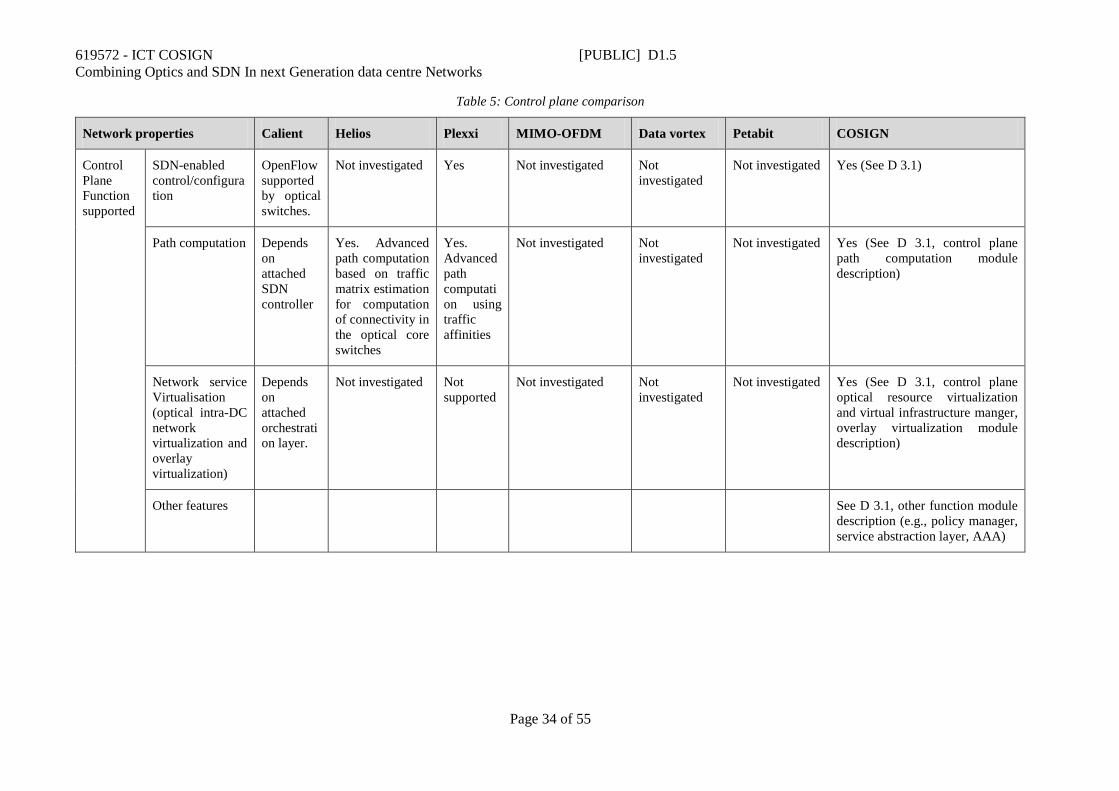
619572 - ICT COSIGN [PUBLIC] D1.5 Combining Optics and SDN In next Generation data centre Networks
Page 34 of 55
Table 5: Control plane comparison
Network properties Calient Helios Plexxi MIMO-OFDM Data vortex Petabit COSIGN
Control Plane Function supported
SDN-enabled control/configuration
OpenFlow supported by optical switches.
Not investigated Yes Not investigated Not investigated
Not investigated Yes (See D 3.1)
Path computation Depends on attached SDN controller
Yes. Advanced path computation based on traffic matrix estimation for computation of connectivity in the optical core switches
Yes. Advanced path computation using traffic affinities
Not investigated Not investigated
Not investigated Yes (See D 3.1, control plane path computation module description)
Network service Virtualisation (optical intra-DC network virtualization and overlay virtualization)
Depends on attached orchestration layer.
Not investigated Not supported
Not investigated Not investigated
Not investigated Yes (See D 3.1, control plane optical resource virtualization and virtual infrastructure manger, overlay virtualization module description)
Other features See D 3.1, other function module description (e.g., policy manager, service abstraction layer, AAA)
619572 - ICT COSIGN [PUBLIC] D1.5 Combining Optics and SDN In next Generation data centre Networks
Page 35 of 55
4 Industrial DCN Roadmaps, Strategies and Techno-economic Analysis
This section presents industrial data centre network roadmaps, strategies and a techno-economic analysis of the involved industrial partners’ value proposition as well as general trends in DC market and operational deployment. The section aims at providing a 5-10 year view forwards based on industry and analyst reports and positions the industrial partners’ foreseen products and services in the data centre network value chain. Roadmaps, strategies and techno-economic analyses are presented for all main focus areas of the COSIGN project.
4.1 DCN virtualization, orchestration, and control Recent analyst reports clearly mark the growing importance of network softwarization for the enterprise and cloud Data Centre market. A study by Infonetics [Infonetics1] informs that 79 percent of surveyed enterprises are planning to have SDN in live production in the data centre in 2017, while 65 percent of survey respondents are currently conducting data centre SDN lab trials or will do so in 2015. Another recent study [Infonetics2] updates that the in-use software-defined networking market, including SDN switches and controllers, will reach $13 billion in 2019. Major drivers behind these trends are the need to better integrate the networking into the next generation ICT services and make network resource configuration more flexible, more automatic, and more converged with the rest of ICT resources, on the one hand, and with the business needs and the workload requirements, on the other.
In this section we cover the most prominent manifestations of the DCN softwarization, namely the network virtualization in Section 4.1.1, the software-driven network control in Section 4.1.3, and the interlocks between the DCN and the overall ICT resource orchestration, in Section 4.1.2.
4.1.1 DCN virtualization Data Centres continue to go virtual, offering increasingly larger portions of compute capacity in virtualized form, e.g. as Virtual Machines (VMs) or containers. In virtualized environments, there are multiple ways to interconnect virtualized entities – virtual compute and virtual storage nodes. For example, this can be accomplished with multiple dedicated network adapters (aka direct assignment), with virtualized network adapters (SRIOV, MRIOV), or with host-based software bridging (VEB, VEPA). While sometimes confused with network virtualization, none of the above listed technologies virtualize the network but merely connect virtualized nodes to physical network.
One well-known and ubiquitously supported network virtualization technology is VLAN. VLAN provides a way to virtualize the physical network on L2 level and can be easily extended into the server virtualization edge whereby virtualized compute and storage nodes are directly connected to the infrastructure VLANs. This combination of server virtualization and network virtualization was deployed to support early virtualized environments and was proven sufficient for a limited scale and a limited extent. As virtualized environments grew in scale and complexity, connecting virtualized nodes to infrastructure VLANs stopped providing a viable solution. One simple example is inability of this technology to allow ‘virtual networks’ to span infrastructure’s L3 boundaries. L3 infrastructure virtualization technologies, like Virtual Routing Forwarding (VRF) can be applied to extend virtualization across L2 boundaries. Still, virtualizing the network infrastructure is not sufficient for multi-tenant network virtualization at scale in environments as it does not fully separate the ‘virtual networks’ from the underlying networking infrastructure.
Modern virtualized environments present requirements above and beyond simple connectivity of virtualized compute and storage entities. Examples of these requirements are: self-service management of user’s virtual networks, including IPAM, not trivial virtual network topologies, and custom connectivity to user’s home network; advanced network services like load balancing, security, acceleration, etc.; quality of service support like bandwidth reservations, rate limiting, and advanced SLAs. Full separation of virtual networks from the networking infrastructure, in terms of technology,
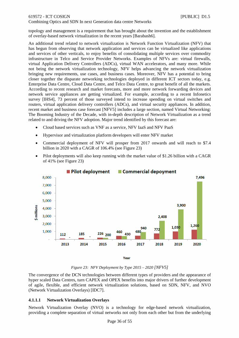
619572 - ICT COSIGN [PUBLIC] D1.5 Combining Optics and SDN In next Generation data centre Networks
Page 36 of 55
topology and management is a requirement that has brought about the invention and the establishment of overlay-based network virtualization in the recent years [Barabash6].
An additional trend related to network virtualization is Network Function Virtualization (NFV) that has begun from observing that network application and services can be virtualized like applications and services of other verticals, to enjoy benefits of consolidating multiple services over commodity infrastructure in Telco and Service Provider Networks. Examples of NFVs are: virtual firewalls, virtual Application Delivery Controllers (ADCs), virtual WAN accelerators, and many more. While not being the network virtualization technology, NFV helps advancing the network virtualization bringing new requirements, use cases, and business cases. Moreover, NFV has a potential to bring closer together the disparate networking technologies deployed in different ICT sectors today, e.g. Enterprise Data Centre, Cloud Data Centre, and Telco Data Centre, to great benefit of all the markets. According to recent research and market forecasts, more and more network forwarding devices and network service appliances are getting virtualized. For example, according to a recent Infonetics survey [IHS4], 73 percent of those surveyed intend to increase spending on virtual switches and routers, virtual application delivery controllers (ADCs), and virtual security appliances. In addition, recent market and business case forecast [NFV5] includes a large section, named Virtual Networking: The Booming Industry of the Decade, with in-depth description of Network Virtualization as a trend related to and driving the NFV adoption. Major trend identified by this forecast are:
• Cloud based services such as VNF as a service, NFV IaaS and NFV PaaS
• Hypervisor and virtualization platform developers will enter NFV market
• Commercial deployment of NFV will prosper from 2017 onwards and will reach to $7.4 billion in 2020 with a CAGR of 106.4% (see Figure 23)
• Pilot deployments will also keep running with the market value of $1.26 billion with a CAGR of 41% (see Figure 23)
Figure 23: NFV Deployment by Type 2015 – 2020 [NFV5]
The convergence of the DCN technologies between different types of providers and the appearance of hyper scaled Data Centres, turn CAPEX and OPEX benefits into major drivers of further development of agile, flexible, and efficient network virtualization solutions, based on SDN, NFV, and NVO (Network Virtualization Overlays) [IDC7].
4.1.1.1 Network Virtualization Overlays
Network Virtualization Overlay (NVO) is a technology for edge-based network virtualization, providing a complete separation of virtual networks not only from each other but from the underlying

619572 - ICT COSIGN [PUBLIC] D1.5 Combining Optics and SDN In next Generation data centre Networks
Page 37 of 55
physical network. Examples of overlay-based network virtualization solutions include VMware NSX, IBM DOVE and SDN VE, Midokura Midonet, Google Andromeda, Microsoft Azure, and more. Solutions differ in approaches to major building blocks and compete in offered features and capabilities, while having the same common structure with the following required constituents: data plane encapsulation protocol, tunnel termination devices (SW or HW), and a mechanism for VM location management (collection and dissemination). In the data plane, different encapsulation protocols are used, e.g. VXLAN, NVGRE, STT, and Geneve. Tunnel termination can be implemented in edge switches, in virtual switches, or in add-on appliances. Location management can be centralized or distributed, SDN-based, or even delegated to the underlying network services, e.g. multicast groups or eVPN can be used for managing VxLAN networks. A virtual network (VN) can be a Layer 2 network or a Layer 3 network, while the physical network can be Layer 2, Layer 3, or a combination, depending on the overlay technology. With overlay network virtualization, data exchanged between VN clients is delivered over the physical network in fragments carrying multiple headers: inner, or virtualization level, headers created by VN clients and outer, or physical level headers, appended by e Network Virtualization Edges (NVEs). The format and the contents of the inner headers depend on the communication protocol in use by the VN clients, while the format and the contents of the outer headers depend both on the communication protocol in use by the NVEs and on the overlay encapsulation format.
NVOs are supported by the majority of vendors that join efforts on standardizing various aspects of the solution though organizations like NVO3 WG of IETF. NVO3 describes the solution as providing isolated Virtual Networks (VNs) identified by their Virtual Network Contexts and comprises multiple Network Virtualization Edge (NVE) modules and a Network Virtualization Authority (NVA). NVE modules intercept traffic generated by VN clients and use encapsulation tunnels to send it over the physical network, while NVA manages the VNs, the tunnels, and, to some extent, the NVE modules. Data sent by VN Clients is intercepted by its hosting NVE module which inspects the packet headers and, in consultation with the NVA, resolves the VN Context and the location of the destination VN client and its hosting NVE module. The source NVE encapsulates the flow’s packets and sends them over the physical network towards the destination NVE which, in consultation with the NVA, decapsulates the packets and delivers them to the source VN Client. To minimize the amount of VN Context and location resolutions, all NVE modules cache the resolved information, preferably for the entire flow duration time. Cache expiration and invalidation due to virtual or physical events, e.g. VM migration, policy updates, port failover, etc., must be seamlessly supported by every specific implementation.
The extent of adoption of NVO can be illustrated by the following analysts’ reports. While Infonetics survey performed in October 2014 [Infonetics2] reported that “… adoption of SDN network virtualization overlays (NVOs) is expected to go mainstream by 2018”, the same survey performed in June 2015 [IHS4] reports that “ … SDN network virtualization overlays (NVOs) will go mainstream in 2016”. In addition, IDC predicts that NVO is promising to become very important to container virtualization, in itself is one of the most important cloud trends expected to grow going forward [IDC7].
Among benefits of NVO as network virtualization approach is its affinity with SDN and NFV trends. One of the main deficiencies of the approach is the performance degradation due to per-packet encapsulation performed in host software. It is clear today that the benefits overweight the deficiencies as major HW vendors are investing in NVO acceleration, e.g. Intel, CISCO, Cavium, etc.
Backed up by the recent trends, the decision to include NVO as part of the proposed COSIGN architecture, is well justified. COSIGN team is going to realize the NVO approach as part of the solution and to extend it with the capabilities of the underlying optical layers of COSIGN.
4.1.2 DCN orchestration As cloud based ICT delivery becomes a reality for many business sectors, about 77 percent of cloud service providers (CSPs) plan to have orchestration software, which brings automation to data centre networks, in live production by 2017 [IHS4]. Recent MarketsandMarkets study [MarketsandMarkets8] reports a tremendous opportunities for growth in the managed cloud based services market for the next five years, as shown in Figure 24.

619572 - ICT COSIGN [PUBLIC] D1.5 Combining Optics and SDN In next Generation data centre Networks
Page 38 of 55
Figure 24: Cloud Managed Service Market [MarketsandMarkets8]
In addition to the fact that all the cloud based services require DCN support to be efficiently developed, provisioned, operated, and delivered to the end customers, there is a huge and growing segment of the whole cloud services market totally devoted to network services, as shown in Figure 25. This market is related to network virtualization, SDN, and NFV trends discussed in the previous subsections and spans both the enterprise and the Telco service providers.
Figure 25: Cloud Managed Service Market, reported for different service type [MarketsandMarkets8]
While the managed service market is going to serve major verticals and thus has a multitude of stake holders, competing in it will be mostly restricted to large DC and Telecommunications providers. One of the reasons is the strong relationship between the success criteria in efficient, agile, secure, and automated service delivery and the ability to execute in the area of DCN orchestration and automation. Integrating the cloud provider network management with the overall resource and services orchestration is beneficial for all the stakeholders. In particular:
• For DC provider, DCN orchestration helps optimizing the network resources usage and increasing the utilization, ultimately bringing down the total costs of ownership and increasing competitiveness and profitability of the DC provider. Typical DCN orchestration use cases for the DC providers are: advanced equipment management, e.g. on-boarding new devices to increase capacity or compensate for failures; rightsizing the provisioned capacity for the demand, e.g. through advanced monitoring, power management, and workload relocations;
• For Cloud Service Provider, DCN orchestration helps optimizing the service development, deployment, operations, and delivery. Some of the benefits are: allowing the services to transparently span multiple data centres and supporting the required service elasticity and velocity.

619572 - ICT COSIGN [PUBLIC] D1.5 Combining Optics and SDN In next Generation data centre Networks
Page 39 of 55
Next generation DCN architecture proposed by COSIGN is largely based on SDN and as such allows for programmatic network management and control, as enabler for advanced cloud resource and services orchestration. According to Infonetics research [Infonetics1], popular data centre SDN use cases include automation for disaster recovery, provisioning, application deployment, and enabling hybrid cloud. Same research highlights that data centre orchestration software represents one of the biggest opportunities for third-party SDN vendors and existing virtualization vendors.
IDC has published an update to its 2014 research of Cloud Management Software market where it confirms earlier predictions for the market growth and extends it further into the future till 2019 [IDC9], see Figure 26. The report also concludes that cloud systems management software, used to enable public, private, and hybrid cloud environments, will continue to demonstrate strong growth during the forecast period. Functional priorities will shift from simply enabling self-service infrastructure provisioning to more dynamic real-time performance analytics and policy-based application/workload deployment, migration, and optimization, e.g. advanced cloud capacity planning, service brokering, and performance analytics in addition to steadily rising demand for self-service provisioning, infrastructure and workload automation and orchestration.
Figure 26: Worldwide Cloud Systems Management Software Revenue, 2010–2019: Comparison
of September 2014 and April 2015 Forecasts [IDC9]
Networking vendors, like CISCO, Alcatel-Lucent, Ericsson, NTT, and others observe these trends, see the benefits of new cloud management trends to data centre networking, and actively compete for opportunities to advance their DCN product to a state matching the cloud management requirements. For example, recent CISCO-sponsored IDC whitepaper [IDC10] states that “to become a resource and not a bottleneck to overall data centre performance, the network must be based on an agile, flexible model rather than a rigid and comparatively outdated model. To accomplish these goals, the network must:
• Be automated and provisioned with greater speed
• Be managed on a programmatic basis
• Offer real-time telemetry and visibility
• Deliver consistent performance at high scale
• Integrate seamlessly with industry-standard cloud orchestration platforms
Companies ranging from cloud service providers to enterprises of all sizes seek a data centre network that delivers not just exceptional performance and scalability — though those remain important
619572 - ICT COSIGN [PUBLIC] D1.5 Combining Optics and SDN In next Generation data centre Networks
Page 40 of 55
considerations — but also unprecedented automation and orchestration that can yield agility, flexibility, and service velocity.”
COSIGN team has identified these trends and has incorporated the orchestrator layer in its proposed next generation DCN architecture. COSIGN orchestrator is a way to provide clear and tangible differentiation to the advanced DCN technologies of the COSIGN SDN control and the COSIGN optical data planes, through integration with the de-facto cloud management standard, the OpenStack.
4.1.3 DCN control Control plane solutions for Data Centre networks are more and more relying on the concept of Software Defined Networking (SDN), with dedicated solutions already available from several major vendors (Cisco, HP, IBM, just to mention some of them), and this trend will likely drive the DCN innovations also in the next years.
The traditional networking model, with coupled hardware and software, had several limitations when applied to DC environments. In fact traditional networks are typically expensive to manage and too rigid to scale without increasing significantly the Total Cost of Ownership. They are usually operated through static pre-configurations which are poorly suitable to handle the dynamicity of the current massive amount of DC traffic. Moreover, they are affected by the well-known lock-in issue: vendor-specific devices with their own proprietary interfaces, algorithms and protocols. Incompatibility issues and poor interoperability prevent effective network deployments that are easy to evolve and extend introducing new devices from different vendors. In this scenario, service providers’ roadmaps were often influenced by the vendors’ plans due to the limited capability to implement and offer innovative services over the existing infrastructures.
In this context, the disruptive SDN paradigm of decoupling forwarding and control plane, combined with open interfaces and centralized management, is particularly effective in data centre environments. Here DC operators are interested in reducing infrastructure management costs, maximizing the infrastructure utilization and introducing new services for their customers with a short time to market. Indeed, SDN has the potential to bring multiple benefits to the management and control of DC networks, with software solutions for the automated provisioning of virtual networks as well as monitoring and optimization of network traffic in DC environments. Programmable interfaces allows to orchestrate and coordinate the configuration of large DC networks through different levels of abstraction and adopting customized solutions to reach a more effective utilization of the DC infrastructure and a more agile tuning of the network behaviour to the highly variable traffic generated by cloud applications.
In particular, there are several key aspects to consider when evaluating the impact of SDN technologies in future DC environments. The extreme level of automation enabled by SDN improves efficiency in cloud service provisioning and reduces costs for DC management, for example removing the need of manual network management and resulting in faster and error-prone service deployment and provisioning.
A key feature in most of the SDN solutions available today is the integration with cloud management platforms, towards a converged management of the entire DC infrastructure, e.g. for integrated load balancing strategies. In this area a promising application of the SDN technology, which may have a relevant role in the future, is related to the optimization of power consumption, for example coordinating the power-off of unneeded switches and servers. Moreover, the flexible nature of SDN solutions allows cloud providers to introduce quickly new functionalities and services. In the next years, the integration of SDN and Network Function Virtualization solutions is foreseen to play an important role for network operators which will have the opportunity to offer a wide set of enhanced network services relying on cloud infrastructures.
In DC and cloud roadmaps, the SDN role is expected to extend in the next years from the core Data Centres to cover also solutions for edge-scale computing, for the pervasive distribution of computing capacity at the edge of the network, closer to the users. On the other hand, the evolution of SDN solutions will also need to follow a parallel direction, in order to cope with the challenges of cloud-scale applications.
619572 - ICT COSIGN [PUBLIC] D1.5 Combining Optics and SDN In next Generation data centre Networks
Page 41 of 55
These three areas are characterized by different requirements which will probably bring to the development of different types of infrastructures followed by specialized SDN platforms and SDN applications. In the first scenario, fundamental features include operational automation, scalability, and seamless infrastructure management for fast deployment of cloud applications. In mobile-edge environments, local scalability issues become less relevant, while the emerging requirements are more focused on inter-site communications, coordinated remote management, security and reduced power consumption. New traffic patterns will likely emerge, driven from new applications in the Internet of Things and Fog Computing area.
Finally, cloud-scale applications (e.g. for big-data, media streaming and transcoding, mobile gaming) will require the efficient orchestration of multi-tenant services across large and distributed environments, and network features able to support high performances and quick scaling of virtual environments. Particularly relevant in this area is the application connectivity awareness to drive the agile deployment of customized virtual environments. In this direction, for example, Cisco is proposing its Application Centric Infrastructure (ACI) solution with an Application Policy Infrastructure Controller that, Cisco claims, will bring savings in DC management. In particular, Cisco declares about 50% in automation and provisioning savings, 21% in network operation savings, 35% in security savings, 25% in CAPEX savings and 45% in power reduction [CISCO11].
While the optical data plane has the most relevant impact on the techno-economic analysis for COSIGN data centres, it is worth to mention also some qualitative considerations associated to the adoption of an SDN-based control plane.
In general, an SDN solution reduces capital expenditures which are related to the purchase of the infrastructure equipment, the first-time installation and test. This is due to the fact that the control logic is moved from the distributed network devices to a centralized SDN controller, allowing to install cheaper devices. In large-size infrastructures with several devices, the additional cost for the SDN controller becomes less relevant and the advantage increases with the growing number of devices that can be managed by a single SDN controller. Other factors that influence the CAPEX cost are the possibility to avoid the vendor lock-in due to the adoption of open interfaces and the improved utilization of the physical infrastructure which limits over-provisioning deployments.
On the operational expenditures side two main factors can be considered: the cost of maintaining the DC infrastructure in an operational status and the Operation, Administration and Management (OAM) cost. SDN may have a beneficial impact on the first aspect, since dedicated applications for traffic optimization can reduce the number of active servers and network devices and automatically manage their switch-off, resulting in lower power consumption.
However, the SDN impact on the second factor is much more relevant. For example in terms of maintenance and repair cost, software upgrade is greatly simplified since mainly limited to the SDN controller itself and requiring more sporadic distributed firmware upgrades. Similarly, centralized control enables more effective periodical test and less expensive preventive maintenance. Similarly, the possibility to create flexible and isolated virtual networks over the underlying physical infrastructure allows for more realistic pre-production test reducing bugs and failures in the production phase. However, the centralized SDN approach requires the proper design of control plane redundancy mechanisms, in order to avoid the single point of failure effect. Even more relevant is the SDN contribution to lower the OAM cost for service provisioning and management, due to the high level of automation which reduces the need of manual network configuration performed by expensive personnel and, at the same time, manages failures and service restorations reducing the network downtime.
4.2 DCN switching technologies
4.2.1 Fast optical Switch Summarising the current state of the art, all current fast optical switches:
• have high insertion loss
• or have high Polarisation Dependent Loss (PDL)
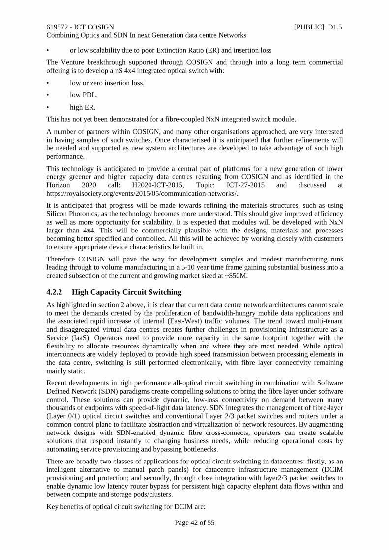
619572 - ICT COSIGN [PUBLIC] D1.5 Combining Optics and SDN In next Generation data centre Networks
Page 42 of 55
• or low scalability due to poor Extinction Ratio (ER) and insertion loss
The Venture breakthrough supported through COSIGN and through into a long term commercial offering is to develop a nS 4x4 integrated optical switch with:
• low or zero insertion loss,
• low PDL,
• high ER.
This has not yet been demonstrated for a fibre-coupled NxN integrated switch module.
A number of partners within COSIGN, and many other organisations approached, are very interested in having samples of such switches. Once characterised it is anticipated that further refinements will be needed and supported as new system architectures are developed to take advantage of such high performance.
This technology is anticipated to provide a central part of platforms for a new generation of lower energy greener and higher capacity data centres resulting from COSIGN and as identified in the Horizon 2020 call: H2020-ICT-2015, Topic: ICT-27-2015 and discussed at https://royalsociety.org/events/2015/05/communication-networks/.
It is anticipated that progress will be made towards refining the materials structures, such as using Silicon Photonics, as the technology becomes more understood. This should give improved efficiency as well as more opportunity for scalability. It is expected that modules will be developed with NxN larger than 4x4. This will be commercially plausible with the designs, materials and processes becoming better specified and controlled. All this will be achieved by working closely with customers to ensure appropriate device characteristics be built in.
Therefore COSIGN will pave the way for development samples and modest manufacturing runs leading through to volume manufacturing in a 5-10 year time frame gaining substantial business into a created subsection of the current and growing market sized at ~$50M.
4.2.2 High Capacity Circuit Switching As highlighted in section 2 above, it is clear that current data centre network architectures cannot scale to meet the demands created by the proliferation of bandwidth-hungry mobile data applications and the associated rapid increase of internal (East-West) traffic volumes. The trend toward multi-tenant and disaggregated virtual data centres creates further challenges in provisioning Infrastructure as a Service (IaaS). Operators need to provide more capacity in the same footprint together with the flexibility to allocate resources dynamically when and where they are most needed. While optical interconnects are widely deployed to provide high speed transmission between processing elements in the data centre, switching is still performed electronically, with fibre layer connectivity remaining mainly static.
Recent developments in high performance all-optical circuit switching in combination with Software Defined Network (SDN) paradigms create compelling solutions to bring the fibre layer under software control. These solutions can provide dynamic, low-loss connectivity on demand between many thousands of endpoints with speed-of-light data latency. SDN integrates the management of fibre-layer (Layer 0/1) optical circuit switches and conventional Layer 2/3 packet switches and routers under a common control plane to facilitate abstraction and virtualization of network resources. By augmenting network designs with SDN-enabled dynamic fibre cross-connects, operators can create scalable solutions that respond instantly to changing business needs, while reducing operational costs by automating service provisioning and bypassing bottlenecks.
There are broadly two classes of applications for optical circuit switching in datacentres: firstly, as an intelligent alternative to manual patch panels) for datacentre infrastructure management (DCIM provisioning and protection; and secondly, through close integration with layer2/3 packet switches to enable dynamic low latency router bypass for persistent high capacity elephant data flows within and between compute and storage pods/clusters.
Key benefits of optical circuit switching for DCIM are:
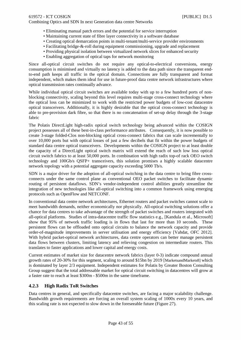
619572 - ICT COSIGN [PUBLIC] D1.5 Combining Optics and SDN In next Generation data centre Networks
Page 43 of 55
• Eliminating manual patch errors and the potential for service interruption • Maintaining current state of fibre layer connectivity in a software database • Creating optical demarcation points in multi-tenant/multi-service provider environments • Facilitating bridge-&-roll during equipment commissioning, upgrade and replacement • Providing physical isolation between virtualized network slices for enhanced security • Enabling aggregation of optical taps for network monitoring
Since all-optical circuit switches do not require any optical-to-electrical conversions, energy consumption is minimised and virtually no latency is added to the data path since the transparent end-to-end path keeps all traffic in the optical domain. Connections are fully transparent and format independent, which makes them ideal for use in future-proof data centre network infrastructures where optical transmission rates continually advance.
While individual optical circuit switches are available today with up to a few hundred ports of non-blocking connectivity, scaling beyond this level requires multi-stage cross-connect technology where the optical loss can be minimized to work with the restricted power budgets of low-cost datacentre optical transceivers. Additionally, it is highly desirable that the optical cross-connect technology is able to pre-provision dark fibre, so that there is no concatenation of set-up delay through the 3-stage fabric
The Polatis DirectLight high-radix optical switch technology being advanced within the COSIGN project possesses all of these best-in-class performance attributes. Consequently, it is now possible to create 3-stage folded-Clos non-blocking optical cross-connect fabrics that can scale incrementally to over 10,000 ports but with optical losses of just a few decibels that fit within the power budgets of standard data centre optical transceivers. Developments within the COSIGN project to at least double the capacity of a DirectLight optical switch matrix will extend the reach of such low loss optical circuit switch fabrics to at least 50,000 ports. In combination with high radix top-of rack OEO switch technology and 100Gb/s QSFP+ transceivers, this solution promises a highly scalable datacentre network topology with a potential aggregate capacity exceeding 5000 Tb/s.
SDN is a major driver for the adoption of all-optical switching in the data centre to bring fibre cross-connects under the same control plane as conventional OEO packet switches to facilitate dynamic routing of persistent dataflows. SDN’s vendor-independent control abilities greatly streamline the integration of new technologies like all-optical switching into a common framework using emerging protocols such as OpenFlow and NETCONF.
In conventional data centre network architectures, Ethernet routers and packet switches cannot scale to meet bandwidth demands, neither economically nor physically. All-optical switching solutions offer a chance for data centres to take advantage of the strength of packet switches and routers integrated with all-optical platforms. Studies of intra-datacentre traffic flow statistics e.g., [Kandula et al., Microsoft] show that 95% of network traffic loading is in flows that last for more than 10 seconds. These persistent flows can be offloaded onto optical circuits to balance the network capacity and provide order-of-magnitude improvements in server utilisation and energy efficiency [Vahdat, OFC 2012]. With hybrid packet-optical network architectures, data centre operators can better manage persistent data flows between clusters, limiting latency and relieving congestion on intermediate routers. This translates to faster applications and lower capital and energy costs.
Current estimates of market size for datacentre network fabrics (layer 0-3) indicate compound annual growth rates of 20-30% for this segment, scaling to around $15bn by 2019 [MarketsandMarkets8] which is dominated by layer 2/3 equipment. Independent estimates for Polatis by Greater Boston Consulting Group suggest that the total addressable market for optical circuit switching in datacentres will grow at a faster rate to reach at least $300m - $500m in the same timeframe.
4.2.3 High Radix ToR Switches Data centres in general, and specifically datacentre switches, are facing a major scalability challenge. Bandwidth growth requirements are forcing an overall system scaling of 1000x every 10 years, and this scaling rate is not expected to slow down in the foreseeable future (Figure 27).
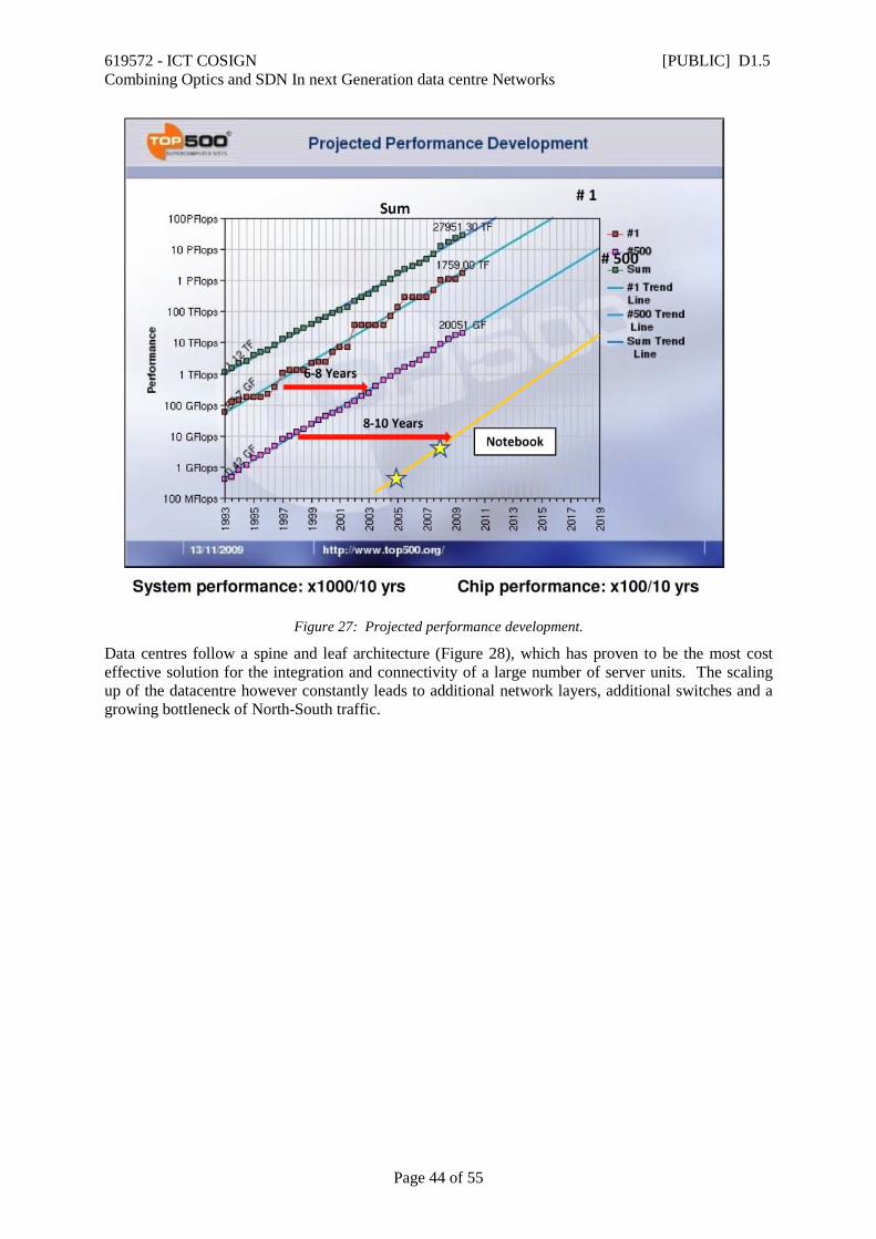
619572 - ICT COSIGN [PUBLIC] D1.5 Combining Optics and SDN In next Generation data centre Networks
Page 44 of 55
Figure 27: Projected performance development.
Data centres follow a spine and leaf architecture (Figure 28), which has proven to be the most cost effective solution for the integration and connectivity of a large number of server units. The scaling up of the datacentre however constantly leads to additional network layers, additional switches and a growing bottleneck of North-South traffic.
619572 - ICT COSIGN [PUBLIC] D1.5 Combining Optics and SDN In next Generation data centre Networks
Page 45 of 55
Figure 28: Data centre spine/leaf architecture.
The clear goal of future ToR (Top of the Rack) Ethernet switches in a data centre architecture, is to increase as much as possible the port count of each single ToR switch. The higher the ToR switch port count (higher radix), the lower the number of overall ToR switch required to support a given number of servers – with all the associated benefits of lower cost, lower power consumption and easier maintenance and support.
Typical ToR switches used today are 48-64 port units in a single 1RU unit. The current architecture suffers from a significant bottleneck, specifically at the layer-2 and layer-3 switches, where 10GE ports are required and the ToR switch suffers from a significant front-panel bandwidth bottleneck, combined with power consumption, heat dissipation and cost constraints.
In COSIGN we are developing, implementing and testing an innovative system architecture for a ToR switch, where mid-board optical design is used, which in turn allows for a significant reduction of the overall system size, a very significant increase in the overall port and bandwidth density of the ToR switch to support much higher system scaling and in parallel a significant reduction in system cost and power consumption.
A 1st prototype has already been implemented, demonstrating a 64 port 10GE ToR switch, which has been reduced to a significantly lower size and footprint, while this supports the design of a 1RU ToR switch with 144 optical interfaces at 10G each – using the same faceplate.
As part of the future roadmap, a 2nd generation board is already being designed with the goal of supporting 128 10GE ports in an even smaller design, which would in turn allow a further increase of at least 2x in the overall system and port density.
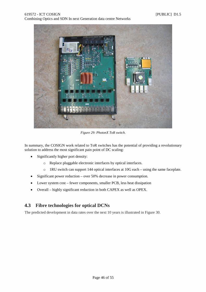
619572 - ICT COSIGN [PUBLIC] D1.5 Combining Optics and SDN In next Generation data centre Networks
Page 46 of 55
Figure 29: PhotonX ToR switch.
In summary, the COSIGN work related to ToR switches has the potential of providing a revolutionary solution to address the most significant pain point of DC scaling:
• Significantly higher port density:
o Replace pluggable electronic interfaces by optical interfaces.
o 1RU switch can support 144 optical interfaces at 10G each – using the same faceplate.
• Significant power reduction – over 50% decrease in power consumption.
• Lower system cost – fewer components, smaller PCB, less heat dissipation
• Overall – highly significant reduction in both CAPEX as well as OPEX.
4.3 Fibre technologies for optical DCNs The predicted development in data rates over the next 10 years is illustrated in Figure 30.
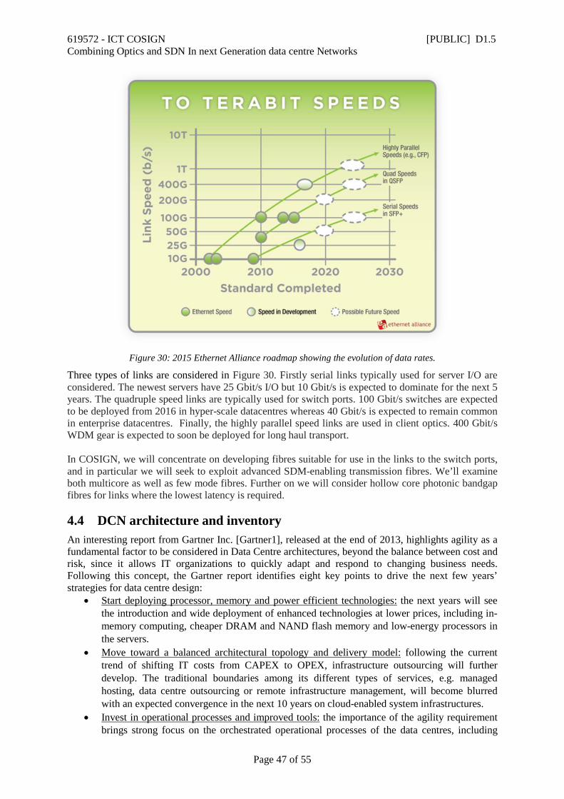
619572 - ICT COSIGN [PUBLIC] D1.5 Combining Optics and SDN In next Generation data centre Networks
Page 47 of 55
Figure 30: 2015 Ethernet Alliance roadmap showing the evolution of data rates.
Three types of links are considered in Figure 30. Firstly serial links typically used for server I/O are considered. The newest servers have 25 Gbit/s I/O but 10 Gbit/s is expected to dominate for the next 5 years. The quadruple speed links are typically used for switch ports. 100 Gbit/s switches are expected to be deployed from 2016 in hyper-scale datacentres whereas 40 Gbit/s is expected to remain common in enterprise datacentres. Finally, the highly parallel speed links are used in client optics. 400 Gbit/s WDM gear is expected to soon be deployed for long haul transport. In COSIGN, we will concentrate on developing fibres suitable for use in the links to the switch ports, and in particular we will seek to exploit advanced SDM-enabling transmission fibres. We’ll examine both multicore as well as few mode fibres. Further on we will consider hollow core photonic bandgap fibres for links where the lowest latency is required.
4.4 DCN architecture and inventory An interesting report from Gartner Inc. [Gartner1], released at the end of 2013, highlights agility as a fundamental factor to be considered in Data Centre architectures, beyond the balance between cost and risk, since it allows IT organizations to quickly adapt and respond to changing business needs. Following this concept, the Gartner report identifies eight key points to drive the next few years’ strategies for data centre design:
• Start deploying processor, memory and power efficient technologies: the next years will see the introduction and wide deployment of enhanced technologies at lower prices, including in-memory computing, cheaper DRAM and NAND flash memory and low-energy processors in the servers.
• Move toward a balanced architectural topology and delivery model: following the current trend of shifting IT costs from CAPEX to OPEX, infrastructure outsourcing will further develop. The traditional boundaries among its different types of services, e.g. managed hosting, data centre outsourcing or remote infrastructure management, will become blurred with an expected convergence in the next 10 years on cloud-enabled system infrastructures.
• Invest in operational processes and improved tools: the importance of the agility requirement brings strong focus on the orchestrated operational processes of the data centres, including
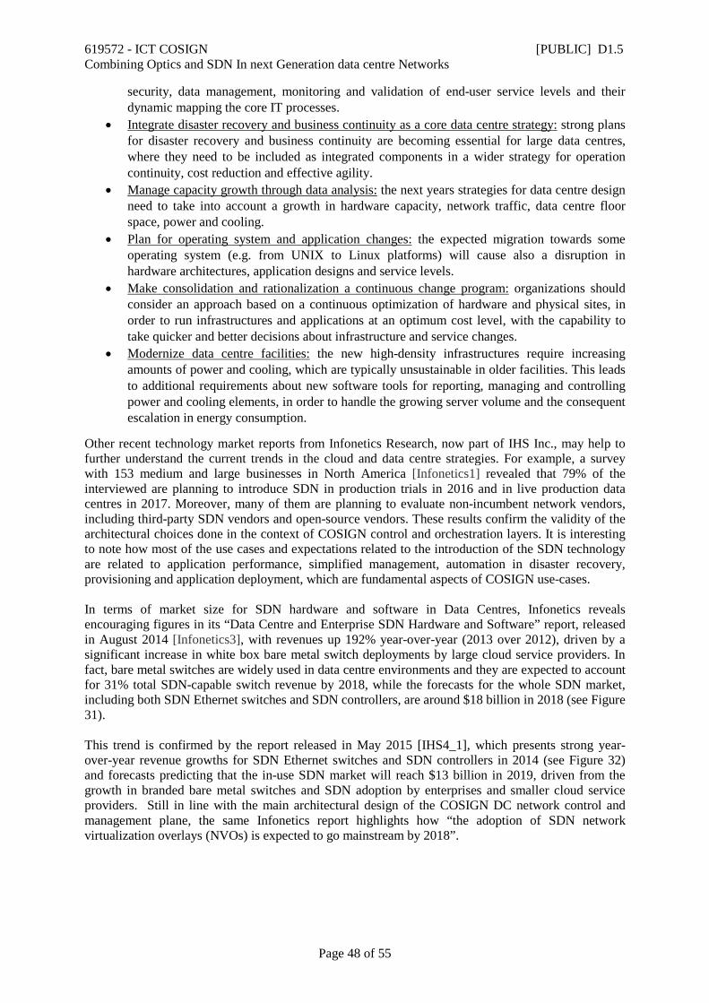
619572 - ICT COSIGN [PUBLIC] D1.5 Combining Optics and SDN In next Generation data centre Networks
Page 48 of 55
security, data management, monitoring and validation of end-user service levels and their dynamic mapping the core IT processes.
• Integrate disaster recovery and business continuity as a core data centre strategy: strong plans for disaster recovery and business continuity are becoming essential for large data centres, where they need to be included as integrated components in a wider strategy for operation continuity, cost reduction and effective agility.
• Manage capacity growth through data analysis: the next years strategies for data centre design need to take into account a growth in hardware capacity, network traffic, data centre floor space, power and cooling.
• Plan for operating system and application changes: the expected migration towards some operating system (e.g. from UNIX to Linux platforms) will cause also a disruption in hardware architectures, application designs and service levels.
• Make consolidation and rationalization a continuous change program: organizations should consider an approach based on a continuous optimization of hardware and physical sites, in order to run infrastructures and applications at an optimum cost level, with the capability to take quicker and better decisions about infrastructure and service changes.
• Modernize data centre facilities: the new high-density infrastructures require increasing amounts of power and cooling, which are typically unsustainable in older facilities. This leads to additional requirements about new software tools for reporting, managing and controlling power and cooling elements, in order to handle the growing server volume and the consequent escalation in energy consumption.
Other recent technology market reports from Infonetics Research, now part of IHS Inc., may help to further understand the current trends in the cloud and data centre strategies. For example, a survey with 153 medium and large businesses in North America [Infonetics1] revealed that 79% of the interviewed are planning to introduce SDN in production trials in 2016 and in live production data centres in 2017. Moreover, many of them are planning to evaluate non-incumbent network vendors, including third-party SDN vendors and open-source vendors. These results confirm the validity of the architectural choices done in the context of COSIGN control and orchestration layers. It is interesting to note how most of the use cases and expectations related to the introduction of the SDN technology are related to application performance, simplified management, automation in disaster recovery, provisioning and application deployment, which are fundamental aspects of COSIGN use-cases. In terms of market size for SDN hardware and software in Data Centres, Infonetics reveals encouraging figures in its “Data Centre and Enterprise SDN Hardware and Software” report, released in August 2014 [Infonetics3], with revenues up 192% year-over-year (2013 over 2012), driven by a significant increase in white box bare metal switch deployments by large cloud service providers. In fact, bare metal switches are widely used in data centre environments and they are expected to account for 31% total SDN-capable switch revenue by 2018, while the forecasts for the whole SDN market, including both SDN Ethernet switches and SDN controllers, are around $18 billion in 2018 (see Figure 31). This trend is confirmed by the report released in May 2015 [IHS4_1], which presents strong year-over-year revenue growths for SDN Ethernet switches and SDN controllers in 2014 (see Figure 32) and forecasts predicting that the in-use SDN market will reach $13 billion in 2019, driven from the growth in branded bare metal switches and SDN adoption by enterprises and smaller cloud service providers. Still in line with the main architectural design of the COSIGN DC network control and management plane, the same Infonetics report highlights how “the adoption of SDN network virtualization overlays (NVOs) is expected to go mainstream by 2018”.
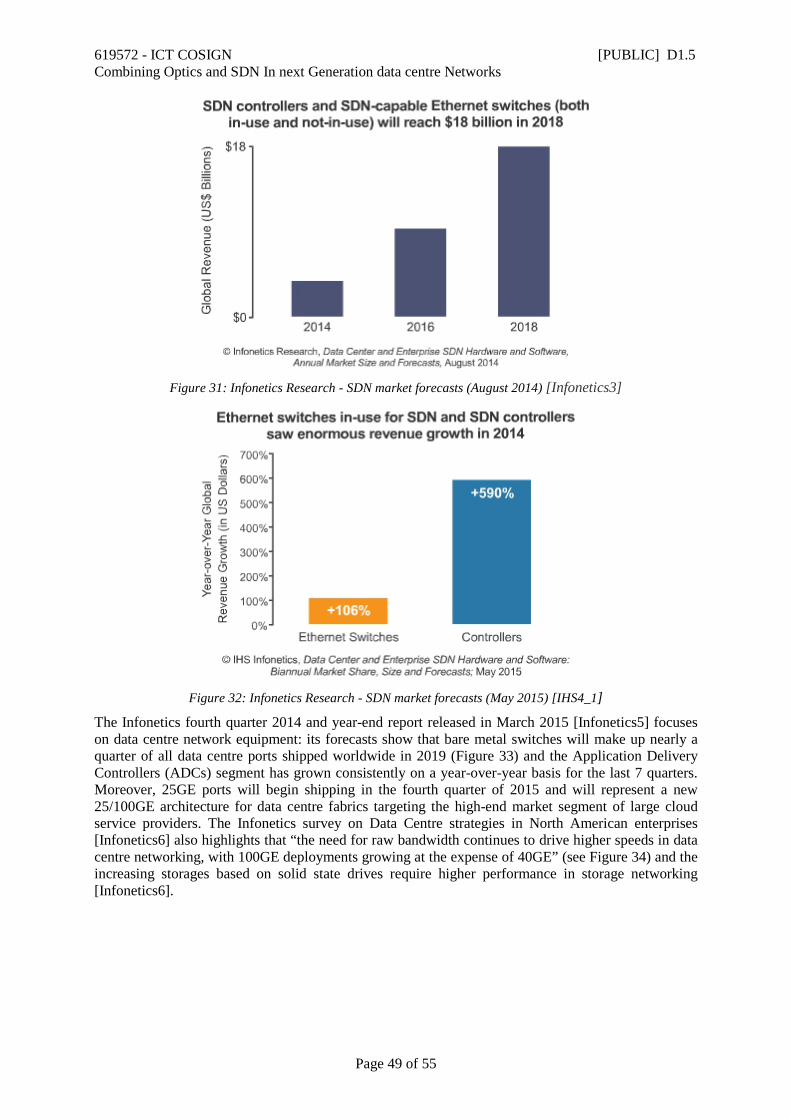
619572 - ICT COSIGN [PUBLIC] D1.5 Combining Optics and SDN In next Generation data centre Networks
Page 49 of 55
Figure 31: Infonetics Research - SDN market forecasts (August 2014) [Infonetics3]
Figure 32: Infonetics Research - SDN market forecasts (May 2015) [IHS4_1]
The Infonetics fourth quarter 2014 and year-end report released in March 2015 [Infonetics5] focuses on data centre network equipment: its forecasts show that bare metal switches will make up nearly a quarter of all data centre ports shipped worldwide in 2019 (Figure 33) and the Application Delivery Controllers (ADCs) segment has grown consistently on a year-over-year basis for the last 7 quarters. Moreover, 25GE ports will begin shipping in the fourth quarter of 2015 and will represent a new 25/100GE architecture for data centre fabrics targeting the high-end market segment of large cloud service providers. The Infonetics survey on Data Centre strategies in North American enterprises [Infonetics6] also highlights that “the need for raw bandwidth continues to drive higher speeds in data centre networking, with 100GE deployments growing at the expense of 40GE” (see Figure 34) and the increasing storages based on solid state drives require higher performance in storage networking [Infonetics6].
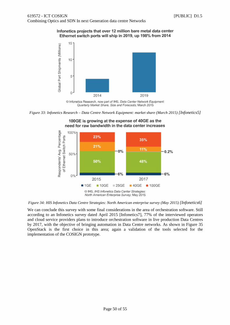
619572 - ICT COSIGN [PUBLIC] D1.5 Combining Optics and SDN In next Generation data centre Networks
Page 50 of 55
Figure 33: Infonetics Research – Data Centre Network Equipment: market share (March 2015) [Infonetics5]
Figure 34: HIS Infonetics Data Centre Strategies: North American enterprise survey (May 2015) [Infonetics6]
We can conclude this survey with some final considerations in the area of orchestration software. Still according to an Infonetics survey dated April 2015 [Infonetics7], 77% of the interviewed operators and cloud service providers plans to introduce orchestration software in live production Data Centres by 2017, with the objective of bringing automation in Data Centre networks. As shown in Figure 35 OpenStack is the first choice in this area; again a validation of the tools selected for the implementation of the COSIGN prototype.

619572 - ICT COSIGN [PUBLIC] D1.5 Combining Optics and SDN In next Generation data centre Networks
Page 51 of 55
Figure 35: HIS Infonetics Data Centre Strategies: Global Service Provider Survey (April 2015) [Infonetics7]
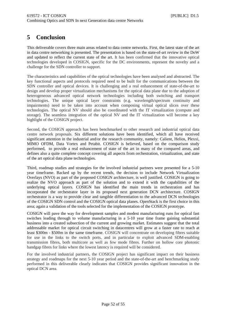
619572 - ICT COSIGN [PUBLIC] D1.5 Combining Optics and SDN In next Generation data centre Networks
Page 52 of 55
5 Conclusion This deliverable covers three main areas related to data centre networks. First, the latest state of the art in data centre networking is presented. The presentation is based on the state-of-art review in the DoW and updated to reflect the current state of the art. It has been confirmed that the innovative optical technologies developed in COSIGN, specific for the DC environments, represent the novelty and a challenge for the SDN controller to support. The characteristics and capabilities of the optical technologies have been analysed and abstracted. The key functional aspects and protocols required need to be built for the communications between the SDN controller and optical devices. It is challenging and a real enhancement of state-of-the-art to design and develop proper virtualization mechanisms for the optical data plane due to the adoption of heterogeneous advanced optical network technologies including both switching and transport technologies. The unique optical layer constraints (e.g. wavelength/spectrum continuity and impairments) need to be taken into account when composing virtual optical slices over these technologies. The optical NV should also be coordinated with the IT virtualization (compute and storage). The seamless integration of the optical NV and the IT virtualization will become a key highlight of the COSIGN project. Second, the COSIGN approach has been benchmarked to other research and industrial optical data centre network proposals. Six different solutions have been identified, which all have received significant attention in the industrial and/or the research community, namely: Calient, Helios, Plexxi, MIMO OFDM, Data Vortex and Petabit. COSIGN is believed, based on the comparison study performed, to provide a real enhancement of state of the art in many of the compared areas, and defines also a quite complete concept covering all aspects from orchestration, virtualization, and state of the art optical data plane technologies. Third, roadmap studies and strategies for the involved industrial partners were presented for a 5-10 year timeframe. Backed up by the recent trends, the decision to include Network Virtualization Overlays (NVO) as part of the proposed COSIGN architecture, is well justified. COSIGN is going to realize the NVO approach as part of the solution and to extend it with the capabilities of the underlying optical layers. COSIGN has identified the main trends in orchestration and has incorporated the orchestrator layer in its proposed next generation DCN architecture. COSIGN orchestrator is a way to provide clear and tangible differentiation to the advanced DCN technologies of the COSIGN SDN control and the COSIGN optical data planes. OpenStack is the first choice in this area; again a validation of the tools selected for the implementation of the COSIGN prototype.
COSIGN will pave the way for development samples and modest manufacturing runs for optical fast switches leading through to volume manufacturing in a 5-10 year time frame gaining substantial business into a created subsection of the current and growing market. Estimates suggest that the total addressable market for optical circuit switching in datacentres will grow at a faster rate to reach at least $300m - $500m in the same timeframe. COSIGN will concentrate on developing fibres suitable for use in the links to the switch ports, and in particular to exploit advanced SDM-enabling transmission fibres, both multicore as well as few mode fibres. Further on hollow core photonic bandgap fibres for links where the lowest latency is required will be considered.
For the involved industrial partners, the COSIGN project has significant impact on their business strategy and roadmaps for the next 5-10 year period and the state-of-the-art and benchmarking study performed in this deliverable clearly indicates that COSIGN provides significant innovation in the optical DCN area.
619572 - ICT COSIGN [PUBLIC] D1.5 Combining Optics and SDN In next Generation data centre Networks
Page 53 of 55
6 References [Cisco] Cisco Data centre Infrastructure 2.5 Design Guide 2011. [Al-Fares] M. Al-Fares, A. Loukissas, and A. Vahdat. A Scalable, Commodity Data centre Network Architecture. SIGCOMM, 2008. [DCell] C. Guo et al. DCell: A Scalable and Fault Tolerant Network Structure for Data centres. SIGCOMM, 08. [BCube] Guo, C.; G. Lu; D. Li; H. Wu; X. Zhang; Y. Shi; C. Tian; Y. Zhang; and S. Lu. 2009. “BCube: A High Performance, Server-centric network Architecture for Modular Data centres,” SIGCOMM 2009. [Kachris] Christoforos Kachris, et al., “Optical Interconnection Networks in Data Centers: Recent Trends and Future Challenges”, IEEE Communications Magazine, September 2013 [Mhamdi] Ali Hammadi, Lotfi Mhamdi, “A Survey on Architectures and Energy Efficiency in Data Center Networks”, in Computer Communications Vol. 40, pp. 1 – 21, 2014. [Xiaomen] Xiaomenr Yi, et al., “Building a Network Highway for Big Data: Architecture and Challenges”, IEEE Network, July/Augusr 2014, pp. 5-13. [MatrixDCN] Yantao Sun, et al., “MatrixDCN: a high performance network architecture for large-scale cloud data centers”, in Wirel. Commun. Mob. Comput. (2015), DOI: 10.1002/wcm.2579. [Microsoft] David Maltz, “SDN and Routing Strategies for Cloud-Scale Data Center Traffic”, in Proc. Of OFC 2015, paper Tu2H.6. [FB] https://code.facebook.com/ [OSA] Kai Chen, et al., ”OSA: An Optical Switching Architecture for Data Center Networks with Unprecedented Flexibility”, in IEEE/ACM Transactions on Networking, Volume 22, Issue 2, pp. 498-511, 2014. [WDM] Christoforos Kachris, et al., ”Power consumption evaluation of hybrid WDM PON networks for data centers”, in Proc. of NOC, July 2011. [WL] O. Liboiron-Ladouceur et al., ”Energy-Efficient Design of a Scalable Optical Multiplane Interconnection Architecture”, in IEEE Journal of Selected Topics in Quantum Electronics Vol. 17, Issue 2, pp. 377-383, 2011 [STIA] Isabella Cherutti et al., ”Optics in Data Center: Improving Scalability and Energy Efficiency”, in Proc. of EuCNC, 2014 [FISSION] Ashwin Gumaste et al., “On The Architectural Considerations of the FISSION (Flexible Interconnection of Scalable Systems Integrated using Optical Networks) Framework for Data-Centers”, in Proc. of ONDM 2013, France. [LIONS] Yawei Yin et al., “LIONS: An AWGR-Based Low-Latency Optical Switch for High-Performance Computing and Data Centers”, in IEEE Journal of Selected Topics in Quantum Electronics, Vol 19, Issue 2, 2013 [TONAK-LION] Roberto Proietti et al., ”Scalable Optical Interconnect Architecture Using AWGR-Based TONAK LION Switch With Limited Number of Wavelengths”, JOURNAL OF LIGHTWAVE TECHNOLOGY, VOL. 31, NO. 24, DECEMBER 15, 2013. [MIMO] P. N. Ji et al., “Design and Evaluation of a Flexible-Bandwidth OFDM-Based Intra Data Center Interconnect,” IEEE J. Sel. Topics Quantum Electronics, vol. 19, no. 2, March 2013. [LIGHTNESS] Albert Pagès et al., ”Performance Evaluation of an All-Optical OCS/OPS-Based Network for Intra-Data Center Connectivity Services”, in Proc. of ICTON 2014. [NEPHELE] http://nephele.anektimito.com.gr/. [All-to-all] Zheng Cao et al., “Experimental Demonstration of Flexible Bandwidth Optical Data Center Core Network With All-to-All Interconnectivity”, JOURNAL OF LIGHTWAVE TECHNOLOGY, VOL. 33, NO. 8, APRIL 15, 2015 [Plexxi] Plexxi, “DATACENTER TRANSPORT FABRIC”, Datasheet available at: http://www.plexxi.com/wp-content/uploads/2014/07/DS_PLX_DTF_20140630.pdf [Calient] “The Hybrid Packet Optical Circuit Switched Datacenter Network,” White paper, Calient Inc., 2012. [Polatis] “The New Optical Data Center,” Polatis Data Sheet, Polatis Inc., 2009. [Helios] Farrington et al.“ Helios: a hybrid electrical/optical switch architecture for modular data centers” Proceeding SIGCOMM '10 Proceedings of the ACM SIGCOMM 2010 conference Pages 339-350. [DDC] Sangjin Han, et al., ”Network Support for Resource Disaggregation in Next-Generation Datacenters”, in Proc. ACM HotNets XII, 2013. [HW] HUAWEI “High Throughput Computing Data Center Architecture - Thinking of Data Center 3.0”, Technical White paper June 2014. [Elby] Stuart Elby, “Evolution of Telecom Carrier Networks to meet Explosions of Cloud Services”, in Proc of OFC 2015, paper Tu2H.5. [ECOC1] Shuangyi Yan , et al., “First demonstration of all-optical programmable SDM/TDM intra data centre and WDM inter- DCN communication,” in Proc. of ECOC 2014, Paper PD 1.2.
619572 - ICT COSIGN [PUBLIC] D1.5 Combining Optics and SDN In next Generation data centre Networks
Page 54 of 55
[ECOC2] Anna Fagertun, et al., ” Ring-based All-Optical Datacenter Networks” To be presented at ECOC 2015. [ECOC3] Valerija Kamchevska et al., ” Experimental Demonstration of Multidimensional Switching Nodes for All-Optical Data Centre Networks” To be presented at ECOC 2015. [JLT] Shuangyi Yan , et al., “Archon: A Function Programmable Optical Interconnect Architecture for Transparent Intra and Inter Data Center SDM/TDM/WDM Networking”, in JLT Vol 33, No 8, pp. 1586 – 1595, April 2015. [Gartner] Gartner Group, “Forecast: x86 Server Virtualization, Worldwide, 2012-2018, 2014 Update”, December 2014. [VMW1] http://www.vmware.com/software-defined-datacenter/index.html [VMW2] http://www.vmware.com [Citrix] http://www.citrix.co.uk/ [Oracle] http://www.oracle.com [D.1.3] COSIGN, Deliverable D1.3, “Comparative analysis of control plane alternatives”, January 2015. [SDxC] SDxCentral Network Virtualization Report 2014, November 2014. [Planet] http://www.cplanenetworks.com/dvnd/ [Infinera] http://www.infinera.com/j7/servlet/NewsItem?newsItemID=444 [Broadcom] https://www.broadcom.com/products/Switching/Data-Center/BCM56960-Series [Cavium] http://www.cavium.com/pdfFiles/CNX880XX_PB_Rev1.pdf [CDFP] http://w ww.cablinginstall.com/articles/2013/03/cdfp-msa-forms.html [IBM] W. Aster et al, JSTQE, Vol. 16, No. 1, pp.234-249 (2010) [Oracle] Po Dong et al, OPTICS EXPRESS, Vol. 18, No. 11, pp.10941-10946 (2010) [HP] L. Zhang et al, JSTQE, VOL. 16, NO. 1 pp.149-158, (2010) [Intel] A. Liu et al, Nature, Vol. 427, pp.615-618, 2004 [Stanford] Y.H. Kuo et al, Nature 437, 1334-1336 (2005) [MIT] J. Liu et al, Nature Photonics 2, 433 - 437 (2008) [Columbia] S. Manipatruni et al, Proc.Lasers and Electro-Optics Soc. 537–538 (2007). [UCSB] H.W. Chen et al, Opt. Express 18, 1070–1075 (2010). [COBO] http://cobo.azurewebsites.net/about.html# [OFC1] Tomofumi Kise, Toshihito Suzuki, Masaki Funabashi, Kazuya Nagashima , Robert Lingle, Durgesh S. Vaidya, Roman Shubochkin and John T. Kamino, Xin Chen, Scott R. Bickham, Jason E. Hurley, Ming-Jun Li, and Alan F. Evans, “Development of 1060nm 25-Gb/s VCSEL and Demonstration of 300m and 500m System Reach using MMFs and Link optimized for 1060nm,” Proceedings of OFC, paper Th4G.3 (2015) [OFC2] Marianne Bigot, Denis Molin, Frank Achten, Adrian Amezcua-Correa, Pierre Sillard, “Extra-Wide-Band OM4 MMF for Future 1.6Tbps Data Communications,” Proceedings of OFC, paper M2C.4 (2015) [Gartner] Gartner Group, “Forecast: x86 Server Virtualization, Worldwide, 2012-2018, 2014 Update”, December 2014. [VMW1] http://www.vmware.com/software-defined-datacenter/index.html [VMW2] http://www.vmware.com [Citrix] http://www.citrix.co.uk/ [Oracle2] http://www.oracle.com [D.13] COSIGN, Deliverable D1.3, “Comparative analysis of control plane alternatives”, January 2015. [SDxC] SDxCentral Network Virtualization Report 2014, November 2014. [Planet] http://www.cplanenetworks.com/dvnd/ [Infinera] http://www.infinera.com/j7/servlet/NewsItem?newsItemID=444 [ofdm-dcn-2012] P. Ji, T. Wang, D. Qian, L. Xu, Y. Aono, T. Tajima, C. Kachris, K. Kanonakis, I. Tomkos, T. Xia, and G. Wellbrock, "Demonstration of High-Speed MIMO OFDM Flexible Bandwidth Data Center Network," in ECOC, 2012, Th.2.B.1. [petabit-2010] K. Xia, Y.-H. Kaob, M. Yangb, and H. J. Chao, “Petabit Optical Switch for Data Center Networks,” in Technical report, Polytechnic Institute of NYU, 2010. [dv-ops-2008] O. Liboiron-Ladouceur, A. Shacham, B. A. Small, B. G. Lee, H. Wang, C. P. Lai, A. Biberman, and K. Bergman, “The data vortex optical packet switched interconnection network,” J. Lightwave Technol., vol. 26, no. 13, pp. 1777–1789, Jul 2008. [ols-2004] F. Xue and S. Ben Yoo. High-capacity multiservice optical label switching for the next-generation internet. Communications Magazine, IEEE, 42(5):S16 – S22, may 2004. [dv-mcn-2007] C. Hawkins, B. A. Small, D. S. Wills, and K. Bergman, “The data vortex, an all optical path multicomputer interconnection network,” IEEE Trans. Parallel Distrib. Syst., vol. 18, pp. 409–420, March 2007. [Infonetics1] Data Center SDN Strategies: North American Enterprise Survey. IHS Infonetics market research. February 2015. [Infonetics2] Data Center and Enterprise SDN Report. Infotetics annual reports. October 2014. [IHS3] Data Center and Enterprise SDN Hardware and Software. IHS Infonetics' biannual reports. June 2015. [IHS4] Data Center Strategies: Global Service Provider Survey. IHS Infonetics' survey. June 2015.
619572 - ICT COSIGN [PUBLIC] D1.5 Combining Optics and SDN In next Generation data centre Networks
Page 55 of 55
[NFV5] Network Function Virtualization (NFV) Business Case, Markets and Forecast 2015 – 2020. 2015 Mind Commerce Publishing. [Barabash6] Katherine Barabash, Rami Cohen, David Hadas, Vinit Jain, Renato Recio, and Benny Rochwerger. 2011. A case for overlays in DCN virtualization. In Proceedings of the 3rd Workshop on Data Center - Converged and Virtual Ethernet Switching (DC-CaVES '11). [IDC7] Cloud and the Network: Driving New Architectures from Datacenter to Access Edge. IDC Analysis, 2015. [MarketsandMarkets8] Cloud Managed Services Market – Global Forecast To 2020. MarketsandMarkets, 2015. [IDC9] Worldwide Cloud Systems Management Software 2015–2019 Forecast. IDC Market analysis, 2015. [IDC10] Optimizing the Datacenter Network for Improved Scalability, Orchestration, and Automation. IDC Technology Spotlight, April 2014. [CISCO11] Cisco, “How to Transition to SDN using CISCO ACI”, July 2014 http://www.slideshare.net/Ciscodatacenter/how-to-transition-to-sdn-using-cisco-aci-webinar [Kandula et al., Microsoft] The nature of data center traffic: measurements & analysis. ACM SIGCOMM 2013. [Vahdat, OFC 12] Delivering Scale Out Data Center: Networking with Optics – Why and How, OFC 2012 [Gartner1] Gartner Inc., “Eight Critical Forces That Will Shape Enterprise Data Center Strategies for the Next Five Years”, November 2013, http://www.gartner.com/resId=2621815 [Infonetics3] Infonetics, “Data Center and Enterprise SDN Hardware and Software”, August 2014, http://www.infonetics.com/pr/2014/Data-Center-and-SDN-Market-Highlights.asp [IHS4_1] IHS, “Data Centre and Enterprise SDN Market to Grow More than 15-fold by 2019”, June 2015, http://www.infonetics.com/pr/2015/2H14-Data-Center-SDN-Market-Highlights.asp [Infonetics5] Infonetics, “Data Center Ethernet Switching Goes Bare Metal”, March 2015, http://www.infonetics.com/pr/2015/4Q14-Data-Center-Network-Equipment-Market-Highlights.asp [Infonetics6] Infonetics, “Software-Defined WAN Taking Hold in the Data Centre”, May 2015, http://www.infonetics.com/pr/2015/Data-Center-Enterprise-Survey-Highlights.asp [Infonetics7] Infonetics, “Cloud Service Providers reveal preferences for Data Center Technologies and Vendors”, June 2015, http://www.infonetics.com/pr/2015/Data-Center-SP-Survey-Highlights.asp


![COSIGN - CORDIS · 2017. 8. 8. · across the software stack. 619572 - ICT COSIGN [PUBLIC] D5.2 Combining Optics and SDN In next Generation data centre Networks . Page 7 of 40 . 1.1](https://img.dokumen.tips/doc/110x75/611940039677986ec677b2c3/cosign-cordis-2017-8-8-across-the-software-stack-619572-ict-cosign-public.jpg)
![COSIGN - CORDIS · 2017. 5. 24. · 619572 - ICT COSIGN [PUBLIC] D4.5 Combining Optics and SDN In next Generation data centre Networks . Page 2 of 33 . Executive Summary . This is](https://img.dokumen.tips/doc/110x75/61001708358e4560d678d6ba/cosign-cordis-2017-5-24-619572-ict-cosign-public-d45-combining-optics.jpg)
![COSIGN - CORDIS€¦ · [2] COSIGN – Deliverable D1.3 – Comparative analysis of control plane alternatives 1.1.2 Acronyms and Abbreviations Most frequently usedacronyms in the](https://img.dokumen.tips/doc/110x75/5f050bed7e708231d410fe05/cosign-cordis-2-cosign-a-deliverable-d13-a-comparative-analysis-of-control.jpg)
![COSIGN - CORDIS · 619572 - ICT COSIGN [PUBLIC] D2.5 Combining Optics and SDN In next Generation data centre Networks Page 7 of 15 2 Second Generation Multi-Core Fibres Suitable for](https://img.dokumen.tips/doc/110x75/5ed2f3d13e92a05e0d15d5a6/cosign-cordis-619572-ict-cosign-public-d25-combining-optics-and-sdn-in-next.jpg)