Embed Size (px)
Citation preview
AECL-6877
ATOMIC ENERGY ^ J f f S S L'ENERGIE ATOMIQUEOF CANADA LIMITED V i B l f DU CANADA LIMITEE
CORROSION PRODUCTS IN POWER GENERATING SYSTEMS
Produits de corrosion dans les centrales thermiques
D.H. LISTER
Chalk River Nuclear Laboratories Laboratoires nucl£aires de Chalk River
Chalk River, Ontario
June 1980 juin
ATOMIC ENERGY OF CANADA LIMITED
CORROSION PRODUCTS IN POWER GENERATING SYSTEMS
by
D.H. Lister
Invited paper presented at the International Conference on theFouling of Heat Transfer Equipment, Rensselaer PolytechnicInstitute, Troy, New York, 1979 August 13-17.
Reprinted from Conference Proceedings published by HemispherePublishing Corporation, 1980.
Copyright: Hemisphere Publishing Corporation19 W. 44th StreetNew York, N.Y. 10036USA
Chalk River Nuclear LaboratoriesChalk River, Ontario KOJ 1J0
1980 June
AECL-6877
L'ENERGIE ATOMIQUE DU CANADA, LIMIT6E
Produits de corrosion dans les centrales thermiques
par
D.H. Lister
Resume
On passe en revue les importants mecanismes du mouvement et de1'encrassement de la corrosion et des produits de corrosion dans lessystemes de caloportage des centrales thermiques. On examine leschaudieres alimentees au mazout et au charbon ainsi que les chaudieresnucleaires en cycle direct et indirect. On fait des commentaires ausujet des systemes de chauffage et de caloportage des centralesthermiques classiques et au sujet du caloporteur primaire et descircuits de production de vapeur des reacteurs refroidis par eau. Lesproduits de corrosion des reacteurs refroidis par un fluide organiqueou un metal liquide peuvent egalement donner lieu a des problemess'ils ne sont pas controles. U s ont, cependant, des effetsbenefiques du cote de l'eau de refroid'.ssement dans les condenseurs.
Laboratoires nucleaires de Chalk RiverChalk River, Ontario KOJ 1J0
Juin 1980
AECL-6877
ATOMIC ENERGY OF CANADA LIMITED
CORROSION PRODUCTS IN POWER GENERATING SYSTEMS
by
D.H. Lister
ABSTRACT
The important mechanisms of corrosion and corrosion productmovement and fouling in the heat transport systems of thermalelectric generating stations are reviewed. Oil- and coal-firedboilers are considered, along with nuclear power systems - bothdirect and indirect cycle. Thus, the fireside and waterside inconventional plants, and the primary coolant and steam-raisingcircuits in water-cooled reactors, are discussed. Corrosionproducts in organic- and liquid-metal-cooled reactors also areshown to cause problems if not controlled, while theirbeneficial effects on the cooling water side of condensers aredescribed.
Chalk River Nuclear LaboratoriesChalk River, Ontario KOJ 1J0
1980 June
AECL-6877
1. INTRODUCTION
Corrosion is expensive. Each year, huge sums of money arespent in trying to slow down the relentless trend of metals toreturn to a more stable state. In industrial nations those sumsamount to three or four percent of the gross national product -a staggering $70 billion in the United States.
The power industry is particularly vulnerable to corrosionand contributes about 9% to the total expenditure. In fact,about half of all maintenance costs in the actual generation ofelectricity are attributable to corrosion [1]. The proportionin thermal generating stations should be considerably higher,for the extreme conditions of temperature, pressure and environ-ment can lead to frequent failure of components and to costlyrepairs and revenue lost through lack of production.
Often corrosion has consequences that are more subtle thanthe direct failure of components, yet in the long run can bejust as disastrous. They are the formation and behaviour ofcorrosion products. Again, thermal power stations are seriouslyaffected. Generally, we expect corrosion products that form onsurfaces in heat transport systems to act as thermal barriers,while corrosion products released to the fluid can depositon other surfaces and impede heat transfer. Also, corrosionproducts can accelerate corrosion in localized areas by concen-trating aggressive chemicals. Further problems can arise innuclear reactor coolants where corrosion products are irradiatedin the core and then move on to contaminate surfaces withradioactivity.
Of course, not all corrosion products are undesirable.Under the right conditions corrosion films reduce the corrosionrates of metals and can actually improve heat transfer, whilecorrosion products or even the corrosion process itself canchange the way in which extraneous scales or fouling films buildup on heat transfer surfaces - sometimes for the better.
Most of the various processes by which corrosion productsmove around heat transport systems and build up on surfacesoccur in thermal generating stations, so this paper has drawnextensively on the experience of the electricity generatingindustry. A brief review of the relevant corrosion mechanismsin heat transport systems leads to a discussion of how corrosionproducts are formed. From the point of view of a surface'sbuilding up a corrosion product film there are two sources toconsider - the surface itself, and elsewhere in the circuit.Corrosion products born elsewhere have to be carried by thefluid, so mechanisms of the transport and deposition of bothparticles and ions are described. The mechanisms depend on thephysical and chemical properties of the fluid, of which tempera-ture, heat flux, flow rate, oxidizing potential and alkalinityare probably the most important.
2. THERMAL GENERATING CYCLES
Steam turbine cycles are the most extensively used togenerate electricity the world over. The major heat sources arethe combustion of coal or oil (the fossil fuels) and nuclearfission.
2.1 Fossil-Fired Plants
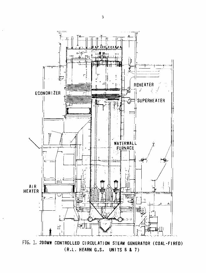
A typical 200 MW(e) coal-fired unit in service with OntarioHydro is illustrated in Figure 1. The boiler delivers 170 kg/s(1.4 x 106 lb/h) of steam at 540°C (1000°F) and 12 MPa(1800 psig) to the turbine.
Around the combustion zone of the boiler, heat istransferred mostly by radiation to the water walls (verticalarrays of tubes containing the boiling water which line thefurnace walls). The combustion gases pass on heat to the super-heaters and reheaters mostly by convection and leave for thestack via the economizer and air heater. The air heaterimproves the overall efficiency by extracting otherwise wastedheat from the stack gases and transferring it to the airrequired for combustion.
Feedwater, preheated by bled steam, enters the boilerthrough the economizer and is turned into steam in the waterwall section. Steam is separated in the steam drum and leavesfor the turbine via the superheater. After the high pressurestage of the turbine, steam is returned to the boiler andreheated before being led to the lower pressure stages.
When the useful energy has been extracted from the steam inthe turbine it is condensed and pumped back to the boilerthrough an ion-exchange purification stage ("condensate polisher")and the preheaters. Purified water from the water treatmentplant is injected into the cycle as required to make up forlosses and blowdown (purging to limit the accumulation ofimpurities).
Note that higher thermodynamic efficiencies can be obtainedfrom units running at higher temperatures. Thus, high-capacityboilers have been designed to produce steam at temperatures upto 650°C and pressures i.i the region of 26 MPa. Such conditionsare in the supercritical region, and boilers that employ them donot have phase separation in a steam drum with recirculation ofthe separated water. Rather, they are once-through units.Although supercritical boilers have a high running efficiency,this can be offset by startup and shutdown inefficiencies,higher capital cost, and the potential for more severe corrosionproblems at the more aggressive operating conditions.
There are three main heat transfer areas where corrosionand corrosion product fouling might be a problem - on thefireside of the boiler, on the waterside of the boiler, and inthe condenser. Each area has its own peculiar problems thatwill be discussed later.
ECONOMIZER
AIRHEATER
REHEATER
SUPERHEATER
WATERWALLFURNACE
FIG. 1. 200MW CONTROLLED CIRCULATION STEAM GENERATOR (COAL-FIRED)(R.L. HEARN G.S. UNITS 6 & 7)
2.2 Nuclear Plants
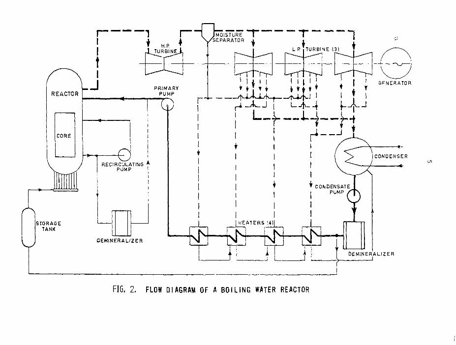
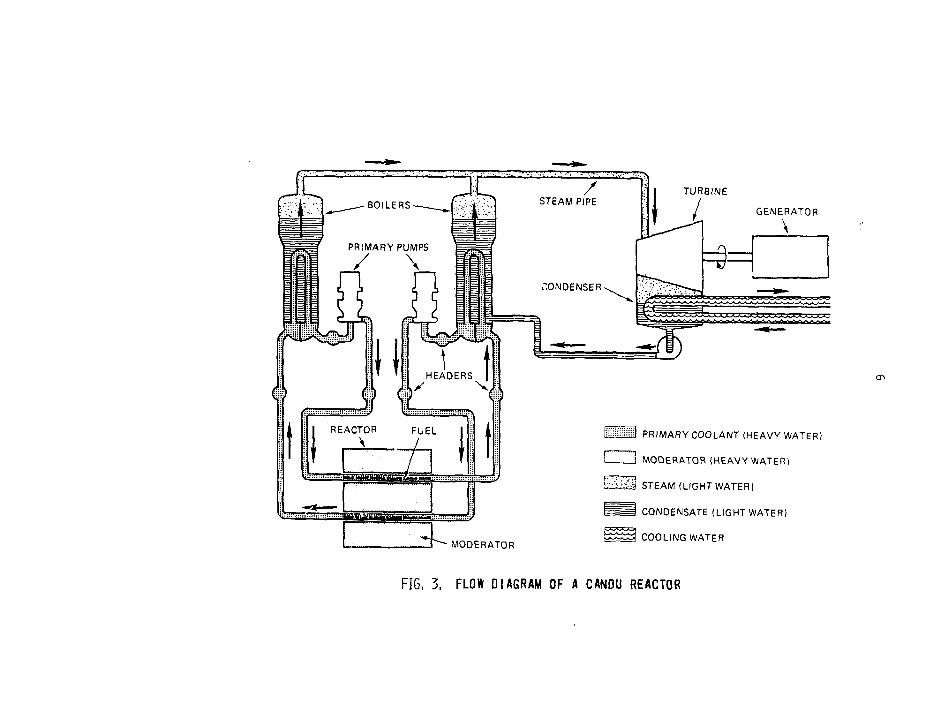
The steam turbine/feedwater sections of nuclear plants aresimilar to those of fossil-fired plants; only the steam-raisingsections are different. There are two types of nuclear steamsupply system (NSSS) to consider - direct cycle and indirectcycle. Boiling water reactors (BWRs) constitute the first type;they boil water in the reactor core and pass the saturated steamat about 287°C directly to the turbine. Indirect cycle reactorshave an intermediate primary fluid to transfer heat from thecore to steam generators where the secondary water is boiled toproduce steam for the turbine. The most common intermediatefluid is water - heavy water in the CANDU system, light water inpressurized water reactors (PWRs). CANDUs produce steam atabout 2 55°C, PWRs at about 285°C.
Figures 2 and 3 illustrate a typical BWR of 715 MW(e)output, and a typical CANDU of 600 MW(e) output. PWRs aredifferent from CANDUs in that their cores are pressure vessels,Vather than calandrias that have horizontal pressure tubes tocontain the fuel and coolant. The pressure tube design keepsthe heavy-water coolant separate from the heavy-water moderatorin the CANDU; in the PWRs and BWRs the light-water coolant alsoserves as moderator, but necessitates having enriched fuel tocounteract neutron losses in the core that arise from parasiticabsorption by H2O. D2O, although not such a good moderatoras H2O, has a much lower parasitic absorption of neutrons andallows CANDUs to run on natural uranium as fuel.
The other indirect cycle reactors with coolant systems thatexhibit potentially serious phenomena of corrosion producttransport and fouling are the liquid-metal-cooled fast breederreactor (LMPBR) and the organic-cooled reactor (OCR). The LMFBRuses liquid sodium or an alloy of sodium and potassium as theprimary coolant to remove heat from the core; the CANDU versionof the OCR is moderated with heavy water (to conserve neutronsand allow natural uranium to be used as fuel) and cooled with apartially hydrogenated mixture of polyphenyls.
3. MATERIALS AND CORROSION
3.1 Fossil-Fired Boilers
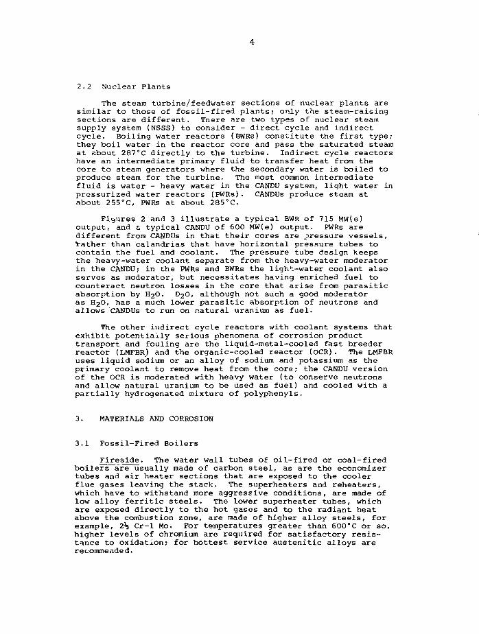
Fireside. The water wall tubes of oil-fired or coal-firedboilers are usually made of carbon steel, as are the economizertubes and air heater sections that are exposed to the coolerflue gases leaving the stack. The superheaters and reheaters,which have to withstand more aggressive conditions, are made oflow alloy ferritic steels. The lower superheater tubes, whichare exposed directly to the hot gases and to the radiant heatabove the combustion zone, are made of higher alloy steels, forexample, 2*5 Cr-1 Mo. For temperatures greater than 600°C or so,higher levels of chromium are required for satisfactory resis-tance to oxidation; for hottest service austenitic alloys arerecommended.
REACTORLJ
CORE
RECIRCULATING APUMP I
DEMINERALIZER
.MOISTURE "~1V/SEPARATOR
FIG, 2, FLOW DIAGRAM OF A BOILING WATER REACTOR
TUR8INE
GENERATOR
\
•MODERATOR
i l i i l i i ) PRIMARY COOLANT (HEAVY WATER)
i J MODERATOR (HEAVY WATER)
l^iiM STEAM (LIGHT WATER)
r = j CONDENSATE (LIGHT WATER)
5 2 2 3 COOLING WATER
FIG. 3. FLOW DIAGRAM OF A CANDU REACTOR
In oxidizing atmospheres both iron and carbon steel formprotective films of oxide, the composition of which varies fromthe reduced iron form FeO (wustite) at the metal/oxide interfaceto the ferric form Fe2O3 (hematite) at the oxide/gas interface,the intermediate phase Fe3C>4 (magnetite) in between [2].
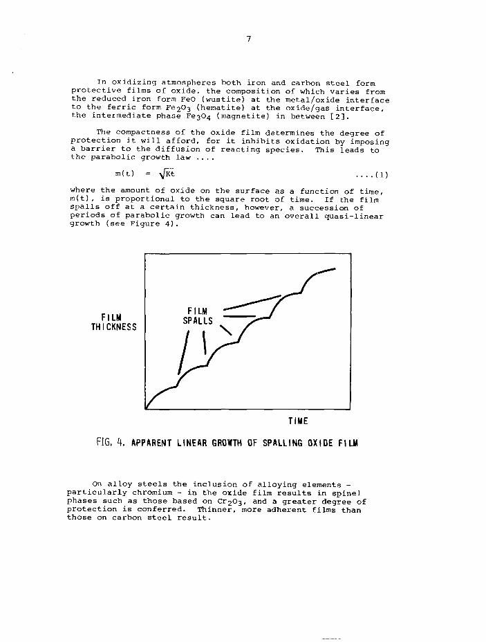
The compactness of the oxide film determines the degree ofprotection it will afford, for it inhibits oxidation by imposinga barrier to the diffusion of reacting species. This leads tothe parabolic growth law ....
m(t) = Kt — (1)
where the amount of oxide on the surface as a function of time,m(t), is proportional to the square root of time. If the filmspalls off at a certain thickness, however, a succession ofperiods of parabolic growth can lead to an overall quasi-lineargrowth (see Figure 4).
FILMTHICKNESS
TIME
FIG. 4. APPARENT LINEAR GROWTH OF SPALLING OXIDE FILM
On alloy steels the inclusion of alloying elements -particularly chromium - in the oxide film results in spinelphases such as those based on 0:203, and a greater degree ofprotection is conferred. Thinner, more adherent films thanthose on carbon steel result.
Normally, on the fireside of boilers, gas-phase corrosionis not a serious problem on materials that are not subjected totemperatures above the recommended range, although chlorides canaccelerate metal attack - particularly on stainless steels wherethe protective spinel oxide can be broken down by reaction withchloride. Conversely, most of the severe corrosion seems torequire the presence of a liquid phase. The trouble is causedby impurities in the fuel, the corrosive elements being chieflyalkali metals and sulphur, with vanadium in many fuel oilscompounding the problems in oil-fired boilers.
In coal-fired boilers deposits of ash or slag aretroublesome. They originate in the fuel as minerals basedmostly on silica, and are a principal cause of loss of heattransfer. Experiments have shown [3] that under typical boilerconditions heat fluxes to a water wall tube can decline to 30%of the clean tube value in less than a day because of fouling.When tube corrosion occurs under deposits at high temperature,alkali sulphates are generally to blame.
Sulphates such as Na2SC>4 or K2SO4, or the correspondingpyrosulphates such as Na2S2O7, form ionic melts on the metalsurfaces. These melts can support electrochemical corrosion ofmetal. Thus, at anodic sites, dissolution occurs
Fe° •+ Fe 3 + + 3e~ (2)
while at cathodic sites the released electrons are consumed byreactions such as ....
O2 + 4e~ -* 2O2~ (3)
or SO42" + 8e~ •* S2~ + 4O2~ (4)
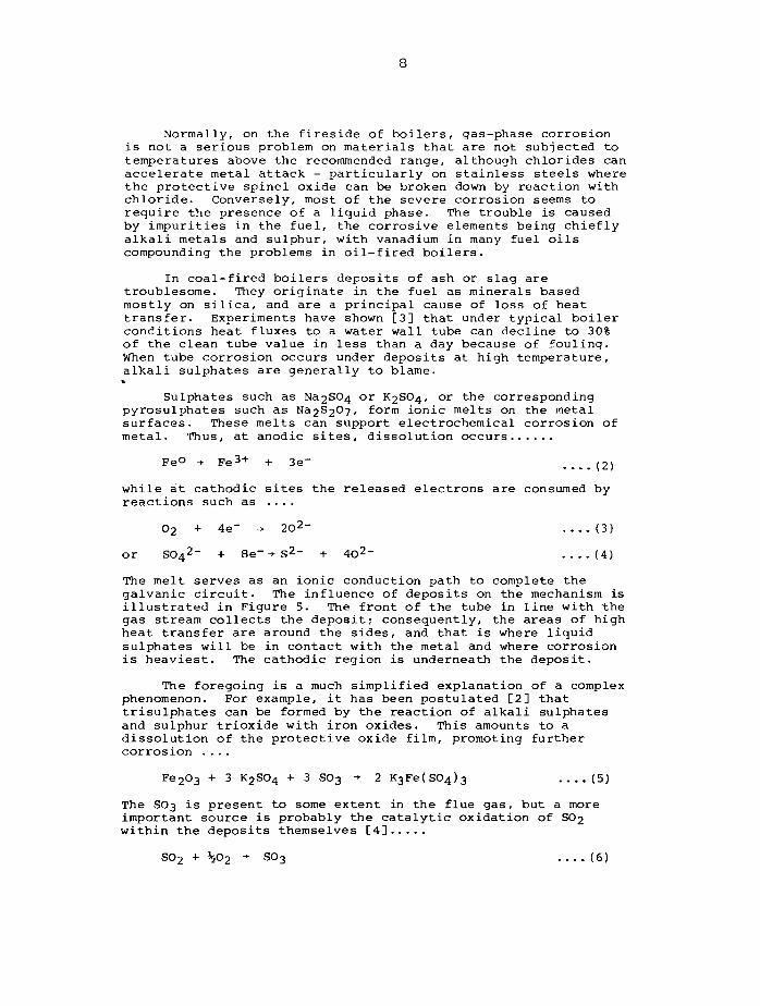
The melt serves as an ionic conduction path to complete thegalvanic circuit. The influence of deposits on the mechanism isillustrated in Figure 5. The front of the tube in line with thegas stream collects the deposit; consequently, the areas of highheat transfer are around the sides, and that is where liquidsulphates will be in contact with the metal and where corrosionis heaviest. The cathodic region is underneath the deposit.
The foregoing is a much simplified explanation of a complexphenomenon. For example, it has been postulated [2] thattrlsulphates can be formed by the reaction of alkali sulphatesand sulphur trioxide with iron oxides. This amounts to adissolution of the protective oxide film, promoting furthercorrosion ....
Fe2O3 + 3 K2SO4 + 3 S03 -»• 2 K3Fe( 804)3 ....(5)
The SO3 is present to some extent in the flue gas, but a moreimportant source is probably the catalytic oxidation of SO2within the deposits themselves [4]
S02 + \02 + SO3 (6)
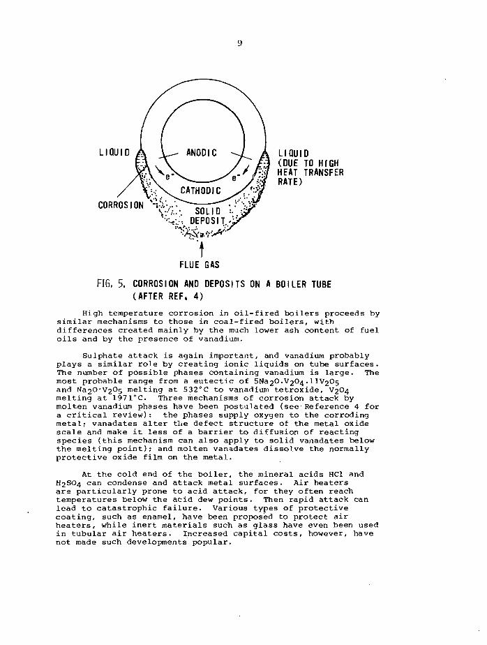
LIQUID LIQUID(DUE TO HIGHHEAT TRANSFERRATE)
CORROSION %
FLUE GAS
FIG, 5. CORROSION AND DEPOSITS ON A BOILER TUBE(AFTER REF. 4)
High temperature corrosion in oil-fired boilers proceeds bysimilar mechanisms to those in coal-fired boilers, withdifferences created mainly by the much lower ash content of fueloils and by the presence of vanadium.
Sulphate attack is again important, and vanadium probablyplays a similar role by creating ionic liquids on tube surfaces.The number of possible phases containing vanadium is large. Themost probable range from a eutectic of 5Na2O.V2O4.IIV2O5and Na2O*V2C>5 melting at 532°C to vanadium tetroxide, V2O4melting at 1971°C. Three mechanisms of corrosion attack bymolten vanadium phases have been postulated (see Reference 4 fora critical review): the phases supply oxygen to the corrodingmetal; vanadates alter the defect structure of the metal oxidescale and make it less of a barrier to diffusion of reactingspecies (this mechanism can also apply to solid vanadates belowthe melting point); and molten vanadates dissolve the normallyprotective oxide film on the metal.
At the cold end of the boiler, the mineral acids HC1 andH2SO4 can condense and attack metal surfaces. Air heatersare particularly prone to acid attack, for they often reachtemperatures below the acid dew points. Then rapid attack canlead to catastrophic failure. Various types of protectivecoating, such as enamel, have been proposed to protect airheaters, while inert materials such as glass have even been usedin tubular air heaters. Increased capital costs, however, havenot made such developments popular.
10
Although the potential for severe problems from depositionand corrosion in fossil-fired boilers is large, satisfactorycontrol is possible. An effective method is the use of lowexcess air, whereby the air supply to the furnace is controlledto give a maximum of about 0.2% oxygen in the flue gases. Suchcontrol is difficult with coal-fired boilers, but in oil-firedunits reductions in all the major modes of corrosion mentionedabove have been achieved, chiefly by the resulting lowering ofSO3 levels in the combustion gases and by limiting the oxida-tion state of vanadium to. the lower oxides such as V2O3 orV2O4 which have higher melting points. Another effectivemethod is the use of fuel additives that counteract catalyticSO3 formation, modify deposits to make them more friable andeasier to remove, and neutralize acids that tend to condense oncool surfaces. Some additives, like magnesia, MgO, reputedlyreact with vanadium oxides to produce higher-melting magnesiumvanadates which are less corrosive. However, additives canactually increase deposits, so the benefits have to be weighedagainst costs of decreased heat transfer.
It seems clear that corrosion and deposition can createserious problems on the fireside of fossil boilers. Althoughcorrosion products grown in situ impair heat transfer, theireffect should be small in comparison with the effects ofextraneous deposits. The contribution of corrosion productsfrom elsewhere in the boiler to those extraneous deposits on asurface is difficult to assess with any certainty; most ironoxides in coal-fired units, for example, seem to originate withminerals such as pyrite in the fuel [5]. Although the spallingof scales and vapour phase transport [6] undoubtedly movecorrosion products through the boiler, they probably contributelittle to the impairment of heat transfer.
Waterside. The corrosion of steels in high temperaturewater and steam depends very much on the quality of the feed-water. That in turn depends upon the quantity and quality ofthe makeup water and the presence of leaks into the system atthe condenser. Makeup water quality can be controlled to withintight limits and should not pose problems unless the filters andion exchange units in the water treatment plant are faulty. Onthe othsr hand, condenser leaks can prove to be disastrous,depending on the water used for cooling. At sea-water-cooledplants, for instance, relatively small leaks can produce highconcentrations of damaging salts in the steam condensate. Undersuch conditions the condensate polisher can become saturatedrapidly and introduce aggressive impurities directly into thefeedwater.
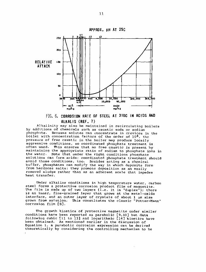
Modern plants like the one described earlier treat theboiler feedwater with volatile chemicals. Hydrazine scavengesoxygen and thereby reduces attack on carbon steel; volatileamines such as morpholine, cyclohexylamine or ammonia maintainsome alkalinity in the boiler water and reduce corrosion rates.Figure 6, taken from Uhlig's book [7], is the classic illustra-tion of how the corrosion rate of carbon steel in water at 310°Cis a minimum at a room temperature pH of 11 to 12. In practice,a pH of about 9 is maintained, depending on the presence in thefeed train of materials such as copper-bearing alloys thatcannot withstand higher alkalinity.
11
APPROX. pH AT 25C
250
RELATIVEATTACK
FIG. 6. CORROSION RATE OF STEEL AT 310C IN ACIDS ANDALKALIS (REF. 7)
Alkalinity may also be maintained in recirculating boilersby additions of chemicals such as caustic soda or sodiumphosphate. Because solutes can concentrate in crevices in theboilei with concentration factors of the order of 104, thepresence of free caustic in the boiler may produce locallyaggressive conditions, so coordinated phosphate treatment isoften used. This ensures that no free caustic is present bymaintaining the appropriate ratio of sodium to phosphate ions inthe water. Note that under the right conditions phosphatesolutions can form acids; coordinated phosphate treatment shouldavoid those conditions, too. Besides acting as a chemicalbuffer, phosphates can modify the way in which deposits formfrom hardness salts; they promote deposition as an easilyremoved sludge rather than as an adherent scale that impedesheat transfer.
Under alkaline conditions in high temperature water, carbonsteel forms a protective corrosion product film of magnetite.The film is made up of two layers (i.e. it is "duplex"); thereis an inner, fine-grained layer that grows at the metal-oxideinterface, and an outer layer of crystals of about 1 ym sizegrown from solution. This constitutes the classic "Potter-Mann"corrosion film [8].
The growth kinetics of protective magnetite under similarconditions have been reported as parabolic [9,10] but datafollowing cubic [11 to 13] and logarithmic [14] kinetics havebeen obtained. As mentioned earlier in the discussion ofEquation 1, a parabolic corrosion expression can be derivedtheoretically by considering the controlling mechanism to be
12
diffusion through the film. Castle and Masterson [9] assumedthat control was by the soluble iron species diffusing outthrough pores. Logarithmic kinetics arise from considering themutual blocking of pores in the film [15] or the increasingprotection afforded by precipitated crystals [14]. A cubicexpression is difficult to justify theoretically on the basis ofa diffusion mechanism [15],- but it is suggested that, because ofthe random nature of second-layer nucleation, corrosion of aparticular carbon steel specimen could be under mixed control sothat the overall kinetic expression is somewhere betweenparabolic and logarithmic - possibly cubic.
Whatever the kinetics of corrosion in high temperaturewater, the solubility of the corrosion products - magnetite oncarbon steel - obviously plays a large part in the mechanism[16]. For the magnetite to exist at all it must be bathed incoolant that is at least saturated in Fe; for the corrosionproduct layer to grow there must be some supersaturation.Furthermore, diffusion of dissolved Fe outward through poresImplies that there is a concentration gradient across the film.Why, then, does magnetite not crystallize in the pores and blockthem? One explanation [10] postulates that the stoichiometry ofthe magnetite varies across the film and creates a correspondingsolubility differential. Another [17] relates the solubility ofmagnetite to the concentration, of dissolved hydrogen arisingfrom the corrosion process itself....
3 Fe + 4 H2O -+ Fe3C>4 + H2 .... (7)
with the solubility equilibrium being....
Fe3O4 + 30H- + H 2 + 2 H 2 O ^ 3 Fe(OH)3- (8)
i.e. the concentration of Fe(II) in solution should beproportional to the one-third power of the hydrogen concentra-tion; the gradient of dissolved hydrogen across the filmprovides the solubility differential to prohibit crystallizationwithin the pores.
On alloy steels too, double-layer films of corrosionproduct are formed [18]. The compositions of the films,however, depend on the alloying constituents. Thus, onaustenitic steels, the inner layer is a chromium-rich spinel,while the outer layer is a ferrite containing some nickel [19].The corrosion mechanisms in high temperature water are similarto those for carbon steel [20,21] and similar time dependencesare expected (for example, cubic corrosion kinetics have beenreported [22] for type 304 stainless steel). Corrosion rates,however, are more than an order of magnitude less than those ofcarbon steel because of the protective nature of the inner,chromium-rich layer. The protective films which give similarlylow corrosion rates on high nickel alloys are also spinels. Forexample, on Inconel-600 NiCr2C>4 is formed [23], althoughother metals such as Fe might be incorporated if ferrous alloysform a significant part of the circuit.
13
High temperature steam also leads to the formation ofduplex corrosion films on steels. Parabolic kinetics arecommon, consistent with a diffusion-controlled mechanism.Apparently, metal ions diffuse outwards - probably along thegrain boundaries of the film - while oxide ions diffuse inwards[24,25]. The outer oxide crystals are generally more tightlypacked than those formed in the water phase, and at very hightemperatures (greater than 500°C) haematite Fe2C>3 ratherthan magnetite may form in the outermost layers. Undersupercritical conditions, when no distinct phase change occurs,the magnetite crystals can form "ripples" - undulations ofperiodicity up to approximately 300 jam - which have a largeeffect on pressure drop. Such undulations have also been notedunder subcritical boiling conditions [26].
Many of the corrosion and heat transfer problems arising onthe waterside of boilers are caused by the influx of corrosionproducts originating in the condenser and feedtrain [27,28]. Aswill be discussed later, those corrosion products foul surfacesand cause local overheating which can promote failure of boilertubes. In particular, copper can plate out as metal andseverely impede boiling heat transfer on porous magnetite films,as well as provide cathodic sites and thereby aggravate thecorrosion of carbon steel.
The sources of the corrosion products in the feedwater arethe condenser itself and the feedwater heaters. Brasses andcopper-nickel alloys have become standard for use as condensertubes. Condensing steam does not generally corrode the tubes tothe extent that the integrity of the condenser is threatened;rather, the biggest difficulty to overcome is corrosion by thecooling water. If highly polluted fresh water or sea water isused foi cooling, a more corrosion-resistant material such astitanium might be specified, though fouling by microorganismsmight then become a problem (copper-containing alloys resistsuch organic fouling).
If the condensate is treated by ion-exchange in a conden-sate polisher, the remaining principal sources of corrosionproducts in the feedtrain are the feedwater heaters. Clearly,the quality of condensate fed to the low pressure heatersdepends upon the efficiency and throughput of the polisher.
Copper-containing alloys are frequently used for thelow pressure heaters, but stainless steel might be employed ifthe release of copper is to be avoided. Note that stainlesssteel is more prone to stress corrosion cracking than non-ferrous alloys, and this disadvantage may offset the benefit ofreduced corrosion product release. For the high pressureheaters carbon steel is generally adequate.
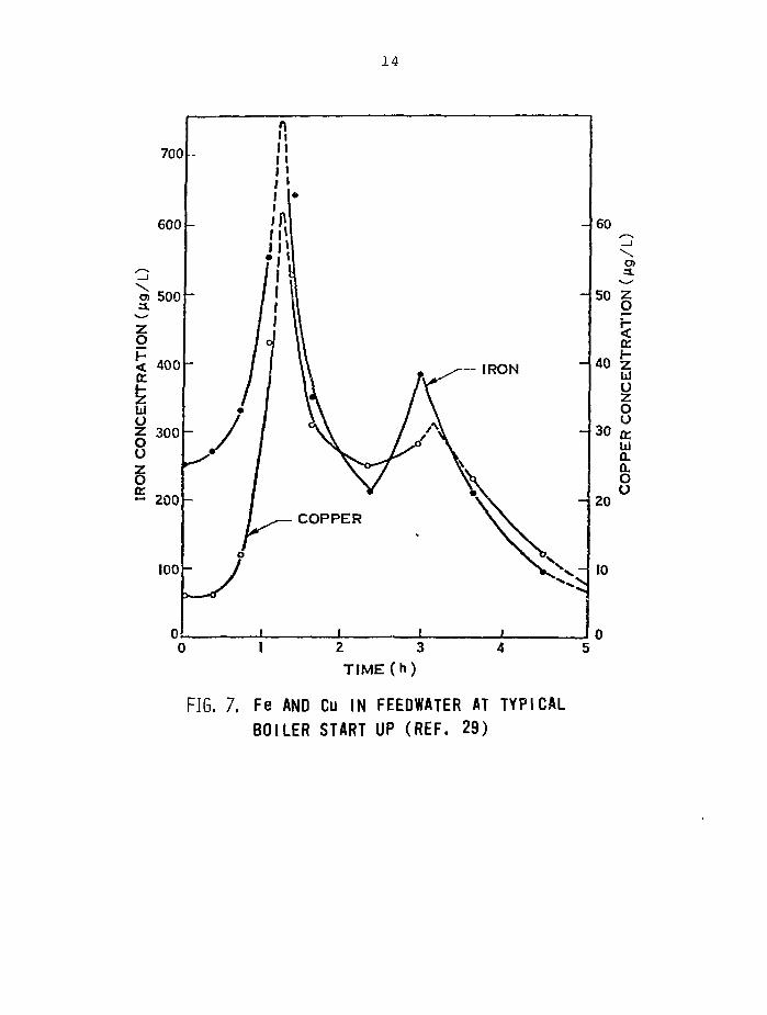
Iron and copper oxides, the predominant corrosion products,are usually present in the feedwater to the extent of a fewug/kg. On startup, however, "bursts" to concentrations of theorder of mg/kg generally occur. Figure 7, reproduced fromReference 29, shows how corrosion products in boiler feedwaterincrease in concentration as the unit is started up. The burst
14
FIG. 7. Fe AND Cu IN FEEDWATER AT TYPICALBOILER START UP (REF. 29)
15
peaking an hour or so after startup is apparently caused by thespalling of scale off surfaces as components expand, as steam isdirected to the shell sides of the heaters and as the normaltemperature differences develop. At about three hours afterstartup, when the boiler is at about half its rated load, asecond, smaller peak occurs. This could be due to the startupof the second condensate pumps and feed pumps, coupled with theeffect of changing the mode of steam supply to the heaters.Corrosion products of nickel and zinc behave similarly to thoseof iron and copper, but the amounts are much less.
3.2 Boiling Water Reactors
As mentioned earlier, the steam turbine and feedw^tersections of nuclear reactors are similar to those of fossil-fired plants. Thus, in the first BWRs, copper-containing alloyswere used for the condenser and the feedwater heaters. Fullflow condensate polishing reduced the influx of corrosionproducts coming directly from the condenser, but downstream ofthe heaters a few tens of ug/kg of iron, copper and nickel weremeasured [30]. These were the major source of impurities in therecirculating loop of the reactor; the stainless steel of thereactor vessel contributed little to the hundreds of \i g/kg ofcorrosion products present in the reactor water itself. At suchconcentrations in the core - bordering on the mg/kg range - witha large proportion of copper, deposition on fuel can impair heattransfer and aggravate rad'-~ctive contamination of out-corecomponents. Consequently, stainless steel has become thepreferred material for the feedwater components of BWRs.
With circuits constructed mostly of stainless steels withsome carbon steel, general corrosion and corrosion productrelease have not caused serious problems in the later BWRs. Thetrouble with stainless steel, however, is that it is prone tostress corrosion cracking if oxygen or ions such as Cl~ arepresent. The purification bypass on the recirculating coolanthelps to reduce such ionic impurities (as well as corrosionproducts), but oxygen is troublesome. Because radiolysis in thecore is difficult to suppress in BWRs, oxygen levels in theprimary coolant are generally of the order of 100 to 200 yg/kg.This range is high enough to have caused cracking of stainlesssteel components in some plants.
It is interesting to contrast the different roles oxygenplays. Thus, while giving problems in the reactor circuit,oxygen has actually been added to reduce the release of corro-sion products from ferritic steels in the feedwater circuit.Maintaining about 30 pg/kg of oxygen can reduce'corrosionproducts by an order of magnitude below the value experiencedwithout oxygen addition. Note that such a concentration ofoxygen in the feedwater has little effect on the concentrationof oxygen in the coolant recirculating through the core.
16
The fuel - as in all modern, water-cooled reactors - issheathed in Zircaloy, an alloy of zirconium. This alloy istransparent to neutrons and develops a protective film ofzirconium oxide, ZrC>2, in high temperature water [31]. Thecorrosion rate of Zircaloy is unaffected by oxygen in theabsence of radiation [32]. Both oxygen and radiation together,however, greatly increase the corrosion rate. Thus BWR fuelsheaths corrode to a greater extent than, say, fuel sheaths inCANDU reactors where oxygen concentrations are much lower.Nevertheless, BWR fuel does operate successfully, and has notshown damaging corrosion or related impairment of heat transferby the buildup of zirconium oxides.
3.3 CANDUs and Pressurized Water Reactors
Cohen's book [33] deals in detail with the chemistry andcorrosion aspects of water-cooled reactors, and concentrates onthe light-water-cooled PWRs. Briefly, those reactors have the"pressure vessel and piping made of stainless steel, and all butthe earliest ones have the steam generators tubed with highnickel alloys such as Inconel-600. Losses of reactivity as thefuel in the core gets depleted are compensated for with asoluble poison - boric acid. Thus, at the start of an operatingcycle the primary coolant contains about 1.8 g/kg of boron, andhas about 2.5 mg/kg of LiOH added to adjust the alkalinity.About 3 to 5 mg/kg of hydrogen are maintained in the coolant tosuppress the production of oxygen by radiolysis in the core. Atthe end of a reactor cycle the boron concentration has fallen toabout 10 mg/kg, and the pH has risen to about 10. Althoughconditions are chemically reducing, and corrosion rates remainlow throughout a reactor cycle, the gradually changing chemistryhas a profound effect on corrosion product movement within theprimary circuit. Such movement has significant consequenceseven at the yg/kg range of corrosion product concentrationsgenerally found in PWRs.
In CANDU reactors the moderator circuit with its facilitiesfor reactivity control by soluble poisons is separate, so thechemistry of the heavy water in the primary coolant circuit canbe controlled within tight limits. LiOH maintains the pH at 10to 10.5, and radiolysis is suppressed by 0.5 to 1 mg/kg ofdissolved hydrogen. Chemistry control is vital for CANDUs, forthe circuit contains large quantities of carbon steel pipingconnecting the Zircaloy pressure tubes in the core with theboilers. Also, early CANDUs used Monel for the boiler tubing,and this necessitates strict maintenance of chemically reducingconditions to minimize corrosion and corrosion product r'iease.For example, during the early operation of the prototype CANDUreactor at Douglas Point radiolysis was not adequatelysuppressed; the resulting oxidizing conditions in the coolantreleased lots of corrosion product from the Monel boiler tubingto the heavy water. Their subsequent transport around thesystem and deposition in the core led to severe contaminationproblems that were only rectified after a concentrated programof study and chemical control [34].
17
Later CANDUs will have some in-core boiling. Under theseconditions radiolysis is not so easy to control with the recom-mended range of dissolved hydrogen because gases are stripped tothe steam phase. The possibility of slight oxidizing conditionsthen means that oxygen-resistant materials such as Inconel orIncoloy have to be used in the boilers.
Apart from the boilers, the secondary coolant circuits ofCANDUs and PWRs resemble the steam and feedwater circuits offossil plants. The potential for in-leakage of impurities intothe steam condensate is therefore present in nuclear systems,too. The consequences can be severe. Also, as in fossilplants, the transport of corrosion products into the boilershould be restricted. The reason is not so much the loss ofheat transfer, for nuclear boilers have excess capacity and donot have the tube overheating problems that occur in fossilboilers with a loss of heat transfer; rather, corrosion productsdepositing in crevices and on tube sheets can provide areaswhere local corrosion can occur - particularly if copper ispresent.
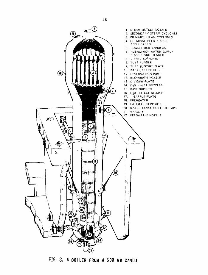
Modern nuclear steam generators are mostly of the recircu-lating, vertical U-tube design (see Figure 8 for a picture of aCANDU steam generator), though Babcock and Wilcox boilers arevertical, once-through units. Primary coolant passes throughthe tubes, and steam is produced on the shell side. Componentsof the steam generators - apart from the tubes - are usuallymade of carbon steel. Thus, aggrossive impurities concentratingin crevices can have disastrous consequences. For example, ifdissolved salts get into the feedwater from condenser leaks,acidic conditions can develop in crevices where boiling occurs -particularly at a sea-water-cooled station. Then, carbon steelcan exhibit fast, linear corrosion [35]. The magnetite corro-sion film that results is non-protective, and allows continuingaccess of the corroding solution to the metal. In some PWRboilers [36], such magnetite growth in the crevices between thenickel alloy tubes and the carbon steel tube support platescreated enough force to "dent" the tubes and deform the plates.The damage has led to costly outages and repairs [37], andresulted in changes in boiler design and reassessments of thecontrol of feedwater chemistry.
3.4 Liquid-Metal-Cooled Reactors
LMFBRs have an intermediate coolant circuit that transfersheat from the primary circuit and raises steam in the secondarycircuit. Both the primary and intermediate circuits use sodiumas the coolant; the intermediate circuit adds a degree of safetyby separating the secondary coolant water from the core circuit,and reduces radiation problems by isolating the highly radio-active primary circuit (Na-23 transmutes to radioactive Na-24 inthe core).
18
STEAM OUTLET NOZZLESECONDARY STEAM CYCLONESPRIMARY STEAM CYCLONESCHEMICAL FEED NOZZLEAND HEADERDOWNCOMER ANNULUSEMERGENCY WATER SUPPLYNOZZLE AND HEADERU BEND SUPPORTSTUBE 3UNDLETUBE SUPPORT PLATEBACK-UP SUPPORTSOBSERVATION PORTBLOWDOWN NOZZLEDIVIDER PLATED20 INLET NOZZLESBASE SUPPORTD20 OUTLET NOZZLE
BAFFLE PLATEPREHEATERLATERAL. SUPPORTSWATER LEVEL CONTROL TAPSMANWAYFEEDWATER NOZZLE
FIG. 8. A BOILER FROM A 600 MW CANDU
19
Primary-loop components are made of stainless steel. Thus,the fuel sheaths and core structure are type 316 stainlesssteel, while the intermediate heat exchanger is type 304.Corrosion in the liquid sodium is apparently governed by theoxygen content of the sodium, and proceeds by a chiefly inter-granular mechanism [38]. Corrosion products are transportedfrom the hot to the cold regions of the circuit, and surfacesdepleted in austenite stabilizers such as nickel and manganeseto the extent of becoming ferritic are left behind. The radio-activity associated with the corrosion products may lead tosignificant radiation fields around components at shutdown.
The materials of the intermediate loop also have towithstand corrosion in liquid sodium, while the boiler has theadded difficulties posed by boiling water and the steam cyclegenerally as discussed earlier. As mentioned above, the inter-mediate, sodium-sodium heat exchanger is austenitic stainlesssteel, while the steam generator is usually a ferritic steelthat will resist local corrosion under the rigorous steam-raising conditions of the secondary side (steam at 482°C and10 MPa from the separate evaporators and superheaters isproposed for the Clinch River reactor). Control of feedwaterchemistry is clearly of prime importance if leaks between thesecondary water circuit and the intermediate sodium loop are tobe avoided.
Again, the oxygen content of the sodium is critical fromthe point of view of corrosion of the components of theintermediate loop, while transport of carbon in the circuitgoverns decarburization of ferritic components and carburizationof low-carbon alloys.
3.5 Organic-Cooled Reactors
The proposed design for a prototype CANDU OCR draws heavilyon the experience gained in the WR-1, organic-cooled researchreactor. The basic concept resembles a standard CANDU in thatthe reactor is a pressure-tube type moderated with heavy water[39]. The core, however, is arranged vertically, so that on-power refuelling is done from the top. The organic coolantleaves the reactor at 400°C and raises steam in standard CANDUboilers of the vzitical U-tube design. The proposed materialsare the ones already in use in standard CANDUs.
The corrosion rates of materials of construction in hotpolyphenyls are very low - about an order of magnitude less thanin high temperature water. On out-core components of carbonsteel, for example, a thin, carbonaceous film quickly builds upto a thickness of a few \im. Some protection for the underlyingmetal is afforded, and subsequent corrosion proceeds slowly,probably under the control of diffusion of reactive species suchas O2 or H2O through the film, to produce an inner film ofmagnetite.
20
The main problem to guard against is hydriding of zirconiumcomponents in the core. During operation, a steady stateconcentration of dissolved hydrogen of about 4 mg/kg is producedin the coolant by radiolysis. Hydrogen sinks in the systemlessen the effects of hydriding of components, while the main-tenance of at least 50 mg/kg of H2O in the coolant ensures theintegrity of the protective oxide film on surfaces and impedeshydrogen uptake. Chlorine impurity in the coolant enhances thehydriding rate, so it must be kept at concentrations below 100yg/kg. As shown later on, the measures to guard againsthydriding are also important from the point of view of fouling.
4. MECHANISMS OF TRANSPORT
The physical differences between the systems of interestare large, for we are considering combustion gases, pressurizedand boiling water, liquid metals and organics. The fundamentalprocesses of fouling by corrosion products in those systems,"however, are largely common. Thus, the mechanisms proposed forthe transport and deposition of particles in turbulent fluidswill be reviewed first; afterwards, molecules or ions will beconsidered.
4.1 Particles in Fluids
The particle sizes of interest range from a fraction of apm - aerosol or colloid size - to several pm. The processes tobe considered include transport in the bulk fluid stream, trans-port across the fluid boundary layer and interaction with thesurface: in detail these processes embody effects such as eddydiffusion, molecular and Brownian diffusion, gravity, thermaland electromagnetic forces and Van der Waals attraction. Notethat an earlier review [40] has already discussed the implica-tions that some of these processes have for the formation ofdeposits in coal-fired boilers, while a later review [41] drewsome general conclusions about the deposition of aerosols. Someof the latter"s conclusions of interest here are
gravity is important in relatively static systems forparticles above about 1 pra;
Brownian diffusion is negligible for sizes over 0.01 pm;
thermophoresis is important for particles below 5 ym, andbecomes dominant at about 0.1 |im;
diffusiophoresis might be important during the condensationof water on cold surfaces
electrical forces become increasingly important on chargedsurfaces as particle size decreases below about O.lpra;for larger particles, very strong electrical fields arerequired to influence deposition.
21
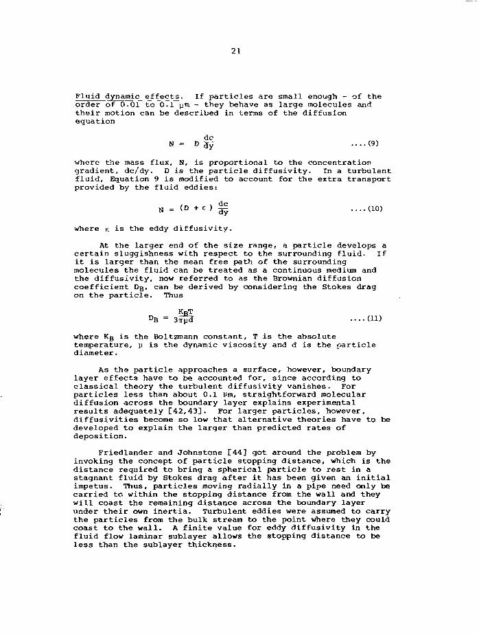
Fluid dynamic effects. If particles are small enough - of theorder of 0.01 to 0.1 ym - they behave as large molecules andtheir motion can be described in terms of the diffusionequation
dcB = D ^ (9)
where the mass flux, N, is proportional to the concentrationgradient, dc/dy. D is the particle diffusivity. In a turbulentfluid, Equation 9 is modified to account for the extra transportprovided by the fluid eddies:
dc
N = (D +e ) ̂ ....(10)
where E is the eddy diffusivity.
At the larger end of the size range, a particle develops acertain sluggishness with respect to the surrounding fluid. Ifit is larger than the mean free path of the surroundingmolecules the fluid can be treated as a continuous medium andthe diffusivity, now referred to as the Brownian diffusioncoefficient DB, can be derived by considering the Stokes dragon the particle. Thus
KRTDB = 3^3 ....(11)
where Kg is the Boltzraann constant, T is the absolutetemperature, p is the dynamic viscosity and d is the particlediameter.
As the particle approaches a surface, however, boundarylayer effects have to be accounted for, since according toclassical theory the turbulent diffusivity vanishes. Forparticles less than about 0.1 Um, straightforward moleculardiffusion across the boundary layer explains experimentalresults adequately [42,43]. For larger particles, however,diffusivities become so low that alternative theories have to bedeveloped to explain the larger than predicted rates ofdeposition.
Friedlander and Johnstone C44] got around the problem byinvoking the concept of particle stopping distance, which is thedistance required to bring a spherical particle to rest in astagnant fluid by Stokes drag after it has been given an initialimpetus. Thus, particles moving radially in a pipe need only becarried to within the stopping distance from the wall and theywill coast the remaining distance across the boundary layerunder their own inertia. Turbulent eddies were assumed to carrythe particles from the bulk stream to the point where they couldcoast to the wall. A finite value for eddy diffusivity in thefluid flow laminar sublayer allows the stopping distance to beless than the sublayer thickness.
22
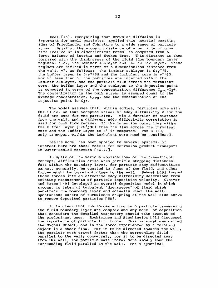
Beal [45], recognizing that Brownian diffusion isimportant for small particles, applied this inertial coastingidea of Friedlander and Johnstone to a wide range of particlesizes. Briefly, the stopping distance of a particle of givensize (called S + in dimensionless terms) is computed from aforce balance of inertia and Stokes drag. This distance is thencompared with the thicknesses of the fluid flow boundary layerregimes, i.e., the laminar sublayer and the buffer layer. Theseregimes are defined in terms of a dimensionless distance fromthe v.all, y+, as follows: the laminar sublayer is 0<y+<5,the buffer layer is 5<y+£30 and the turbulent core is y+>30.For S + less than 5, the particles are injected within thelaminar sublayer, and the particle flux across the turbulentcore, the buffer layer and the sublayer to the injection pointis computed in terms of the concentration difference CaVg-Cg+.The concentration in the bulk stream is assumed equal to theaverage concentration, CaVg, and the concentration at theinjection point is Cg+.
The model assumes that, within eddies, particles move withthe fluid, so that accepted values of eddy diffusivity e for thefluid are used for the particles. eis a function of distancefrom t.ie wall, and a different eddy diffusivity correlation isused for each flow regime. If the injection point lies withinthe buffer layer (5<S*£30) then the flux across the turbulentcore and the buffer layer to S + is computed. For S+>30,only transport within the turbulent core need be considered.
Beal's model has been applied to several systems; ofinterest here are those models for corrosion product transportin water-cooled reactors [46,47].
In spite of the various applications of the free-flightconcept, difficulties arise when particle stopping distancesfall within the boundary layer, for particle eddy diffusivitiescannot, generally, be equated to those of the fluid, and otherforces might be important close to the wall. Sehmel [48] lumpedthose forces into an effective eddy diffusivity determined fromexisting measurements of particle deposition velocity. Cleaverand Yates [49] developed an overall deposition model in whichaccount is taken of turbulent "downsweeps" of fluid whichpenetrate the boundary layer and actually reach the wall.Spontaneous bursts of turbulence erupting at the wall also serveto remove deposited particles [50].
It is clear that the forces acting on a particle traversingthe fluid boundary layer are complex and any model of depositionthat considers the detailed trajectory should take account ofthe predominant ones. Rouhiainen and Stachiewicz [51] discussedthe importance of particle lift force. This is sometimes calledthe Magnus Effect, and is the force experienced by a rotatingobject in a shear flow. For it to be directed towards the wall,the particle must travel faster than the surrounding fluidparallel to the wall; conversely, for it to be directed awayfrom the wall, the particle must travel more slowly than thesurrounding fluid paralled to the wall. For a spherical
23
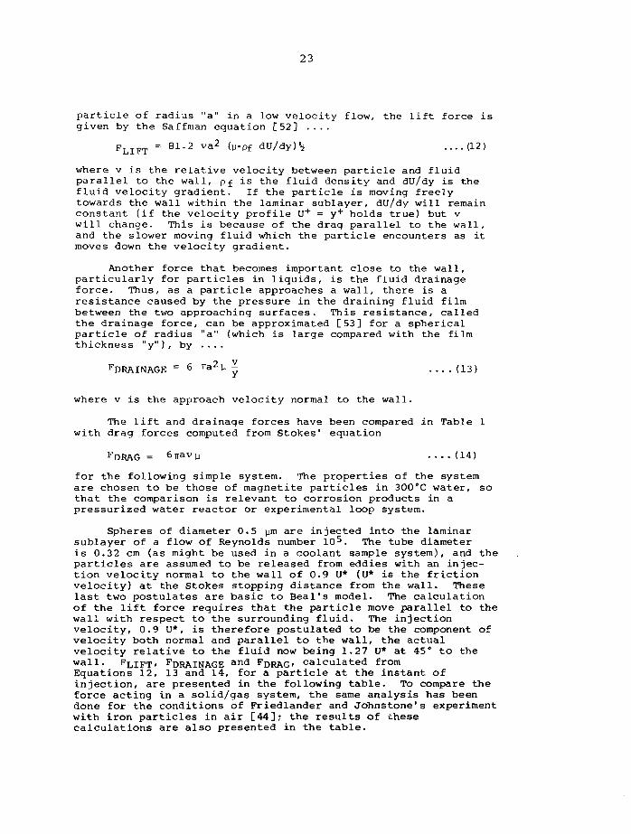
particle of radius "a" in a low velocity flow, the lift force isgiven by the Saffman equation [52] ....
F L I F T = 81.2 va2 (jj.pf 6V/6y)h ....(12)
where v is the relative velocity between particle and fluidparallel to the wall, pf is the fluid density and du/dy is thefluid velocity gradient. If the particle is moving freelytowards the wall within the laminar sublayer, du/dy will remainconstant (if the velocity profile U + = y+ holds true) but vwill change. This is because of the drag parallel to the wall,and the slower moving fluid which the particle encounters as itmoves down the velocity gradient.
Another force that becomes important close to the wall,particularly for particles in liquids, is the fluid drainageforce. Thus, as a particle approaches a wall, there is aresistance caused by the pressure in the draining fluid filmbetween the two approaching surfaces. This resistance, calledthe drainage force, can be approximated [53] for a sphericalparticle of radius "a" (which is large compared with the filmthickness "y"), by ....
FDRAINAGE = 6 v&2 V ̂ (13)
where v is the approach velocity normal to the wall.
The lift and drainage forces have been compared in Table 1with drag forces computed from Stokes' equation
FDRAG = Snavp ....(14)
for the following simple system. The properties of the systemare chosen to be those of magnetite particles in 300°C water, sothat the comparison is relevant to corrosion products in apressurized water reactor or experimental loop system.
Spheres of diameter 0.5 pm are injected into the laminarsublayer of a flow of Reynolds number 105. The tube diameteris 0.32 cm (as might be used in a coolant sample system), and theparticles are assumed to be released from eddies with an injec-tion velocity normal to the wall of 0.9 U* (U* is the frictionvelocity) at the Stokes stopping distance from the wall. Theselast two postulates are basic to Beal's model. The calculationof the lift force requires that the particle move parallel to thewall with respect to the surrounding fluid. The injectionvelocity, 0.9 U*, is therefore postulated to be the component ofvelocity both normal and parallel to the wall, the actualvelocity relative to the fluid now being 1.27 U* at 45° to thewall. F Li F T, F D R A I N A G E and F D R A G, calculated fromEquations 12, 13 and 14, for a particle at the instant ofinjection, are presented in the following table. To compare theforce acting in a solid/gas system, the same analysis has beendone for the conditions of Friedlander and Johnstone's experimentwith iron particles in air [44]; the results of thesecalculations are also presented in the table.
24
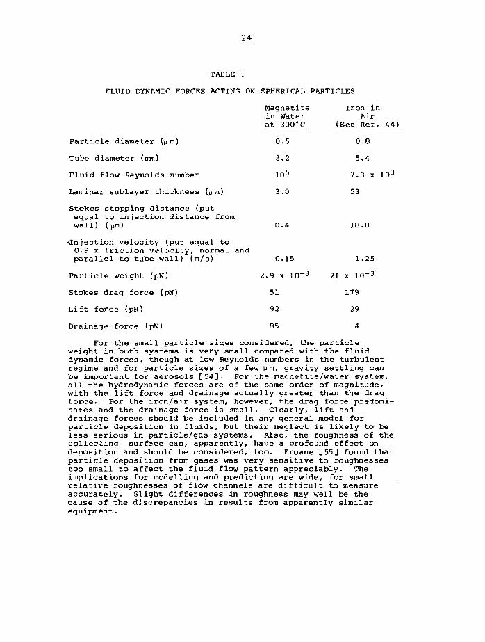
TABLE 1
FLUID DYNAMIC FORCES ACTING ON SPHERICAL PARTICLES
Magnetite Iron inin Water Airat 300°C (See Ref. 44)
Particle diameter (pm) 0.5 0.8
Tube diameter (mm) 3.2 5.4
Fluid flow Reynolds number 105 7.3 x 10³
Laminar sublayer thickness (pm) 3.0 53
Stokes stopping distance (putequal to injection distance fromwall) (pin) 0.4 18.8
injection velocity (put equal to0.9 x friction velocity, normal andparallel to tube wall) (m/s) 0.15 1.25
Particle weight (pN) 2.9 x 10~3 21 x 10~3
Stokes drag force (pN) 51 179
Lift force (pN) 92 29
Drainage force (pN) 85 4
For the small particle sizes considered, the particleweight in both systems is very small compared with the fluiddynamic forces, though at low Reynolds numbers in the turbulentregime and for particle sizes of a few pm, gravity settling canbe important for aerosols [54]. For the magnetite/water system,all the hydrodynamic forces are of the same order of magnitude,with the lift force and drainage actually greater than the dragforce. For the iron/air system, however, the drag force predomi-nates and the drainage force is small. Clearly, lift anddrainage forces should be included in any general model forparticle deposition in fluids, but their neglect is likely to beless serious in particle/gas systems. Also, the roughness of thecollecting surface can, apparently, have a profound effect ondeposition and should be considered, too, Browne [55] found thatparticle deposition from gases was very sensitive to roughnessestoo small to affect the fluid flow pattern appreciably. Theimplications for modelling and predicting are wide, for smallrelative roughnesses of flow channels are difficult to measureaccurately. Slight differences in roughness may well be thecause of the discrepancies in results from apparently similarequipment.
25
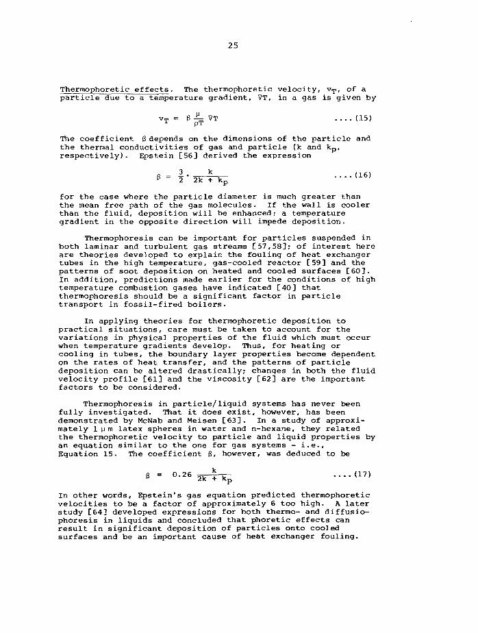
Thermophoretic effects. The thermophoretic velocity, vT, of aparticle due to a temperature gradient, VT, in a gas is given by
vT = 0 ^ VT .... (15)
The coefficient 6 depends on the dimensions of the particle andthe thermal conductivities of gas and particle (k and kp,respectively). Epstein [56] derived the expression
<16)
for the case where the particle diameter is much greater thanthe mean free path of the gas molecules. If the wall is coolerthan the fluid, deposition will be enhanced; a temperaturegradient in the opposite direction will impede deposition.
Thermophoresis can be important for particles suspended inboth laminar and turbulent gas streams [57,58]; of interest hereare theories developed to explain the fouling of heat exchangertubes in the high temperature, gas-cooled reactor [59] and thepatterns of soot deposition on heated and cooled surfaces [60].In addition, predictions made earlier for the conditions of hightemperature combustion gases have indicated [40] thatthermophoresis should be a significant factor in particletransport in fossil-fired boilers.
In applying theories for thermophoretic deposition topractical situations, care must be taken to account for thevariations in physical properties of the fluid which must occurwhen temperature gradients develop. Thus, for heating orcooling in tubes, the boundary layer properties become dependenton the rates of heat transfer, and the patterns of particledeposition can be altered drastically; changes in both the fluidvelocity profile [61] and the viscosity [62] are the importantfactors to be considered.
Thermophoresis in particle/liquid systems has never beenfully investigated. That it does exist, however, has beendemonstrated by McNab and Meisen [63]. In a study of approxi-mately l p m latex spheres in water and n-hexane, they relatedthe thermophoretic velocity to particle and liquid properties byan equation similar to the one for gas systems - i.e..Equation 15. The coefficient g, however, was deduced to be
• • • • ( 1 7 )
In other words, Epstein's gas equation predicted thermophoreticvelocities to be a factor of approximately 6 too high. A laterstudy [64] developed expressions for both thermo- and diffusio-phoresis in liquids and concluded that phoretic effects canresult in significant deposition of particles onto cooledsurfaces and be an important cause of heat exchanger fouling.
26
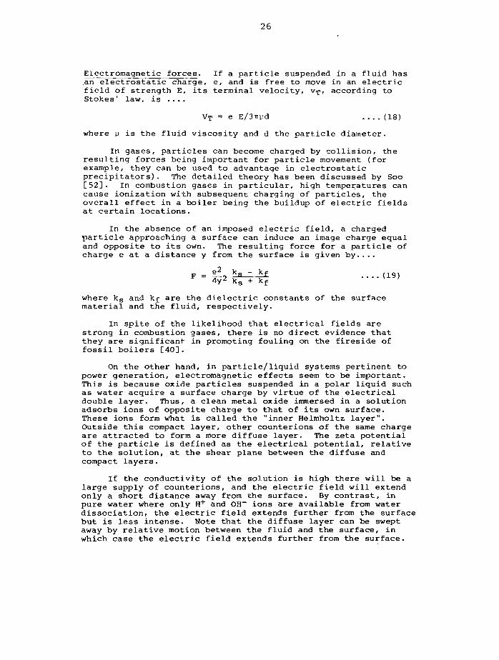
Electromagnetic forces. If a particle suspended in a fluid hasan electrostatic charge, e, and is free to move in an electricfield of strength E, its terminal velocity, Vrp, according toStokes' law, is ....
VT = e E/3TT)jd .... (18)
where y is the fluid viscosity and d the particle diameter.
In gases, particles can become charged by collision, theresulting forces being important for particle movement (forexample, they can be used to advantage in electrostaticprecipitators). The detailed theory has been discussed by Soo[52]. In combustion gases in particular, high temperatures cancause ionization with subsequent charging of particles, theoverall effect in a boiler being the buildup of electric fieldsat certain locations.
In the absence of an imposed electric field, a chargedparticle approaching a surface can induce an image charge equaland opposite to its own. The resulting force for a particle ofcharge e at a distance y from the surface is given by....
F = i£2 *s ~ *f (19)4y ks + kf
where ks and kf are the dielectric constants of the surfacematerial and the fluid, respectively.
In spite of the likelihood that electrical fields arestrong in combustion gases, there is no direct evidence thatthey are significant in promoting fouling on the fireside offossil boilers [40].
On the other hand, in particle/liquid systems pertinent topower generation, electromagnetic effects seem to be important.This is because oxide particles suspended in a polar liquid suchas water acquire a surface charge by virtue of the electricaldouble layer. Thus, a clean metal oxide immersed in a solutionadsorbs ions of opposite charge to that of its own surface.These ions form what is called the "inner Helmholtz layer".Outside this compact layer, other counterions of the same chargeare attracted to form a more diffuse layer. The zeta potentialof the particle is defined as the electrical potential, relativeto the solution, at the shear plane between the diffuse andcompact layers.
If the conductivity of the solution is high there will be alarge supply of counterions, and the electric field will extendonly a short distance away from the surface. By contrast, inpure water where only H + and 0H~ ions are available from waterdissociation, the electric field extends further from the surfacebut is less intense. Note that the diffuse layer can be sweptaway by relative motion between the fluid and the surface, inwhich case the electric field extends further from the surface.
27
Metal oxides immersed in aqueous solutions tend to havehydrated surfaces, and therefore to exhibit acidic or basicproperties depending on the dissociation of the surface groups.Thus, as the solution pH changes, the surface charge changes asthe balance between H + and OH~ ions on the surface changes.At the isolectric point of surface, IEPS, equal numbers of posi-tive and negative ions are adsorbed and the surface has no netcharge; the pH at which this occurs is called the point of zerocharge, PZC, and is a characteristic of the type of oxide.Clearly, in a coolant system made of different materials ofconstruction that have different PZCs, and in which there aresuspended particles of corrosion products, again havingdifferent PZCs, the differences in charge between particles andsurfaces will promote or hinder deposition. Such electrokineticeffects are also important for the agglomeration of colloids [65],but as yet few fundamental studies have been done on thedetailed surface chemistry of corrosion product particles inhigh temperature coolants; in fact only a few of the many lowtemperature values of PZC reported by Parks [66] have beenextended to higher temperatures [67,68,69].
In a flowing system, abrupt changes in fluid shear - suchas occur around obstacles - can induce large components ofstreaming potential that are normal to the flow direction [70].As Cohen has pointed out [71] these potentials can provide thedriving force for particles to deposit on obstructions such asflow orifices where fluid shear rates are high.
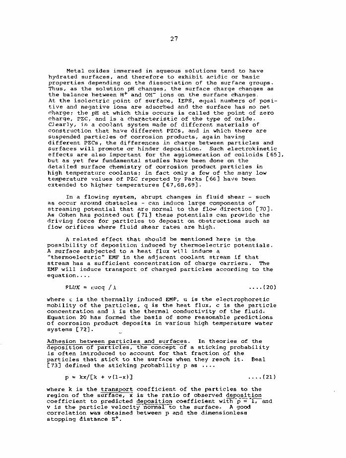
A related effect that should be mentioned here is thepossibility of deposition induced by thermoelectric potentials.A surface subjected to a heat flux will induce a"thermoelectric" EMF in the adjacent coolant stream if thatstream has a sufficient concentration of charge carriers. TheEMF will induce transport of charged particles according to theequation....
FLUX = eucq / \ ....(20)
where e is the thermally induced EMF, u is the electrophoreticmobility of the particles, q is the heat flux, c is the particleconcentration and X is the thermal conductivity of the fluid.Equation 20 has formed the basis of some reasonable predictionsof corrosion product deposits in various high temperature watersystems [72].
Adhesion between particles and surfaces. In theories of thedeposition of particles, the concept of a sticking probabilityis often introduced to account for that fraction of theparticles that stick to the surface when they reach it. Beal[73] defined the sticking probability p as ....
p = kx/[k + v(l-x)] (21)
where k is the transport coefficient of the particles to theregion of the surface, x is the ratio of observed depositioncoefficient to predicted deposition coefficient with p = 1, andv is the particle velocity normal to the surface. A goodcorrelation was obtained between p and the dimensionlessstopping distance S+.
28
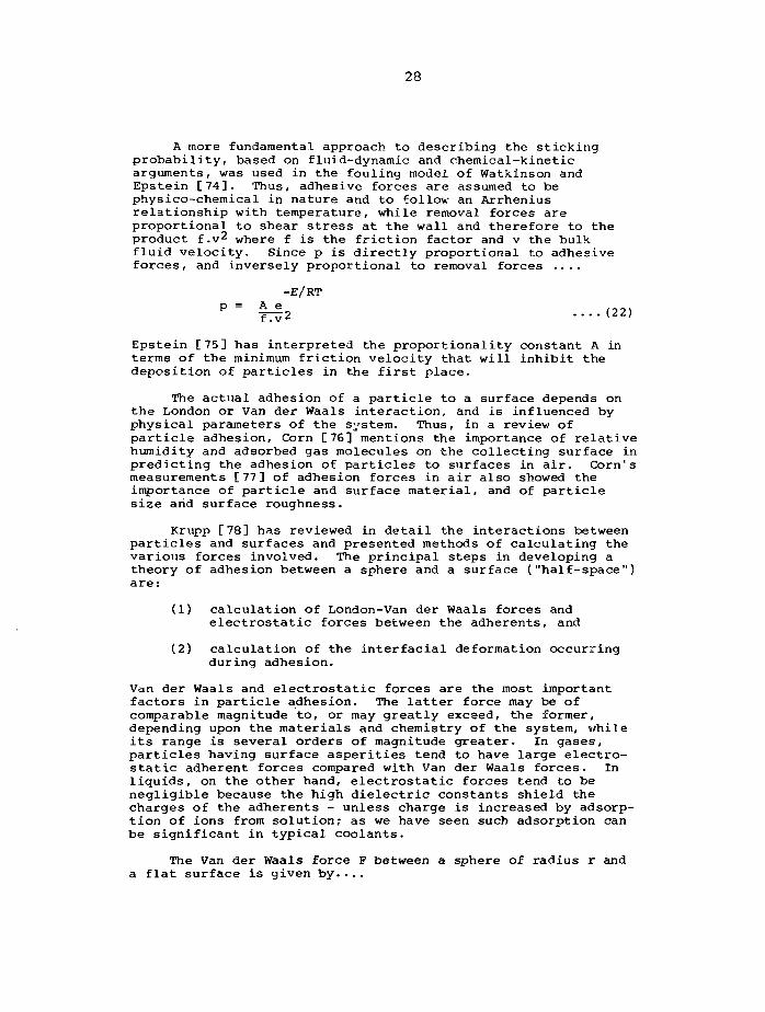
A more fundamental approach to describing the stickingprobability, based on fluid-dynamic and chemical-kineticarguments, was used in the fouling model of Watkinson andEpstein [74]. Thus, adhesive forces are assumed to bephysico-chemical in nature and to follow an Arrheniusrelationship with temperature, while removal forces areproportional to shear stress at the wall and therefore to theproduct f.v2 where f is the friction factor and v the bulkfluid velocity. Since p is directly proportional to adhesiveforces, and inversely proportional to removal forces ....
-E/RT
P = ^ 2 ••••(22)
Epstein [75] has interpreted the proportionality constant A interms of the minimum friction velocity that will inhibit thedeposition of particles in the first place.
The actual adhesion of a particle to a surface depends onthe London or Van der Waals interaction, and is influenced byphysical parameters of the system. Thus, in a review ofparticle adhesion. Corn [76] mentions the importance of relativehumidity and adsorbed gas molecules on the collecting surface inpredicting the adhesion of particles to surfaces in air. Corn'smeasurements [77] of adhesion forces in air also showed theimportance of particle and surface material, and of particlesize arid surface roughness.
Krupp [78] has reviewed in detail the interactions betweenparticles and surfaces and presented methods of calculating thevarious forces involved. The principal steps in developing atheory of adhesion between a sphere and a surface ("half-space")are:
(1) calculation of London-Van der Waals forces andelectrostatic forces between the adherents, and
(2) calculation of the interfacial deformation occurringduring adhesion.
Van der Waals and electrostatic forces are the most importantfactors in particle adhesion. The latter force may be ofcomparable magnitude to, or may greatly exceed, the former,depending upon the materials and chemistry of the system, whileits range is several orders of magnitude greater. In gases,particles having surface asperities tend to have large electro-static adherent forces compared with Van der Waals forces. Inliquids, on the other hand, electrostatic forces tend to benegligible because the high dielectric constants shield thecharges of the adherents - unless charge is increased by adsorp-tion of ions from solution; as we have seen such adsorption canbe significant in typical coolants.
The Van der Waals force F between a sphere of radius r anda flat surface is given by....
29
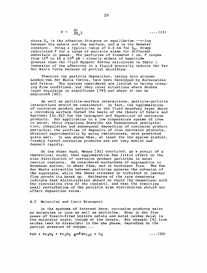
F= i o2 ....(23)
where Z o is the adhesion distance or equilibrium —sningbetween the sphere and the surface, and H is the Hamakerconstant. Using a typical value of 0.4 nm for Zo, Kruppcalculated F for a range of particle sizes for differentmaterials in gases. For particles of diameter 1 urn, F rangesfrom lO^ to 18 x 10^ pN - clearly orders of magnitudegreater than the fluid dynamic forces calculated in Table 1-Immersion of the adherents in a liquid generally reduces the Vander Waals force because of partial shielding.
Theories for particle deposition, taking into accountLondon-Van der Waals forces, have been developed by Ruckensteinand Prieve. The systems considered are limited to having creep-ing flow conditions, but they cover situations where doublelayer repulsion is significant [79] and where it can beneglected [80].
As well as particle-surface interactions, particle-particleinteractions should be considered. In fact, the agglomerationof corrosion product particles in the fluid boundary layer above& corroding surface formed the basis of the theory of Kabele andBartlett [81,82] for the transport and deposition of corrosionproducts. For application to a low temperature system of ironin water, their equations describe the homogeneous precipita-tion, coagulation and subsequent deposition of corrosion productparticles; the profiles of deposits of iron corrosion products,obtained experimentally by using radiotracers, were predictedquite well. It was shown that, at least for the system studied,freshly formed corrosion products are not very mobile anddeposit rapidly.
On the other hand, Means [83] concluded, as a result of atheoretical study, that agglomeration has little effect on thesize distribution of corrosion product particles in waterreactor coolants. He considered mechanisms of aggregation inBrownian motion, in shear flow, and in turbulent flow. The Vander Waals attraction between particles governs the cohesion ofthe aggregate, while the shear stresses in turbulent or laminarflow govern its break up. Estimates of the rate constantsindicate that disintegration should be rapid (by comparison withthe circulation rate of the coolant), and that the resultingsmall perturbation of the particle size distribution should notaffect deposition rates.
4.2 Molecular and Ionic Transport
In the systems of interest here, corrosion products existas molecules or ions as well as particles. Even in the fluegases of fossil-fired boilers metals and metal oxides exist inthe molecular state, though at low levels. For example [6] ironoxides tend to dissociate in the gas phase, depending on thepartial pressure of oxygen....
FeO + Fe3C>4 + Fe2(>3 ^=^Fe(g) + O2 ....(24)
30
while chromium oxides form a range of species in an oxidizingenvironment....
Cr2O3 •+ CrO + CrO2 + CrO3 + 0 + 0 2 •••• (25)
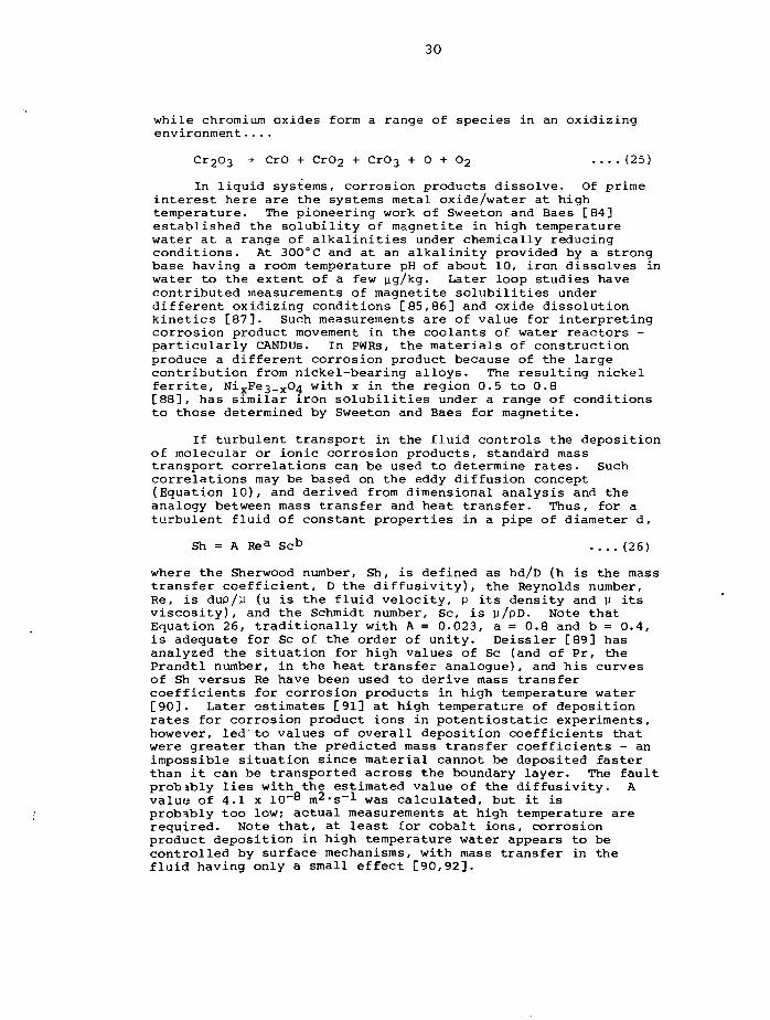
In liquid systems, corrosion products dissolve. Of primeinterest here are the systems metal oxide/water at hightemperature. The pioneering work of Sweeton and Baes [84]established the solubility of magnetite in high temperaturewater at a range of alkalinities under chemically reducingconditions. At 300°C and at an alkalinity provided by a strongbase having a room temperature pH of about 10, iron dissolves inwater to the extent of a few yg/kg. Later loop studies havecontributed measurements of magnetite solubilities underdifferent oxidizing conditions [85,86] and oxide dissolutionkinetics [87]. Such measurements are of value for interpretingcorrosion product movement in the coolants of water reactors -particularly CANDUs. In PWRs, the materials of constructionproduce a different corrosion product because of the largecontribution from nickel-bearing alloys. The resulting nickelferrite, NixFe3_xC>4 with x in the region 0.5 to 0.8[88], has similar iron solubilities under a range of conditionsto those determined by Sweeton and Baes for magnetite.
If turbulent transport in the fluid controls the depositionof molecular or ionic corrosion products, standard masstransport correlations can be used to determine rates. Suchcorrelations may be based on the eddy diffusion concept(Equation 10), and derived from dimensional analysis and theanalogy between mass transfer and heat transfer. Thus, for aturbulent fluid of constant properties in a pipe of diameter d,
Sh = A Rea Scb (26)
where the Sherwood number, Sh, is defined as hd/D (h is the masstransfer coefficient, D the diffusivity), the Reynolds number,Re, is dup/y (u is the fluid velocity, p its density and y itsviscosity), and the Schmidt number, Sc, is y/pD. Note thatEquation 26, traditionally with A = 0.023, a = 0.8 and b = 0.4,is adequate for Sc of the order of unity. Deissler [89] hasanalyzed the situation for high values of Sc (and of Pr, thePrandtl number, in the heat transfer analogue), and his curvesof Sh versus Re have been used to derive mass transfercoefficients for corrosion products in high temperature water[90]. Later estimates [91] at high temperature of depositionrates for corrosion product ions in potentiostatic experiments,however, led to values of overall deposition coefficients thatwere greater than the predicted mass transfer coefficients - animpossible situation since material cannot be deposited fasterthan it can be transported across the boundary layer. The faultprobibly lies with the estimated value of the diffusivity. Avalu« of 4.1 x 10~8 m^'s"^ was calculated, but it isprobably too low? actual measurements at high temperature arerequired. Note that, at least for cobalt ions, corrosionproduct deposition in high temperature water appears to becontrolled by surface mechanisms, with mass transfer in thefluid having only a small effect [90,92].
31
In organic coolants, corrosion and corrosion producttransport seems to be governed by the presence of impurities.Thus, in the CANDU OCR, chlorine in the coolant attacks thepiping and forms an Fe-Cl complex in solution [93].
In liquid metals, the relative importances of dissolved andparticulate corrosion products have not yet been fully sortedout [94]; however it is interesting to learn that the fissionproducts which are present in the LMFBR coolant and which formoxides are mostly in the form of suspended fine particles [95].
5. EXPERIMENTS AND DEPOSITION MODELS
As implied throughout this paper so far, studies of thefouling in power systems by corrosion products have concentratedon the steam-raising cycle and on the primary coolants ofnuclear reactors. In the following summary of that work, someoverlap with earlier reviews is inevitable. In particular, therecent comprehensive paper by Epstein [75] on fouling studies ingeneral will be mentioned at the outset, for it covers severalof the models that are to be discussed later.
5.1 Deposition in Boiling Water
It is well established that corrosion products on boilersurfaces have a profound effect on heat transfer; in fact,chemical cleaning of boilers is often practised on a routinebasis to avoid problems of tube overheating or corrosionaggravated by deposits. Corrosion products originating else-where in the system are usually to blame [96], though there issome evidence that in situ corrosion products can be equallydamaging [97].
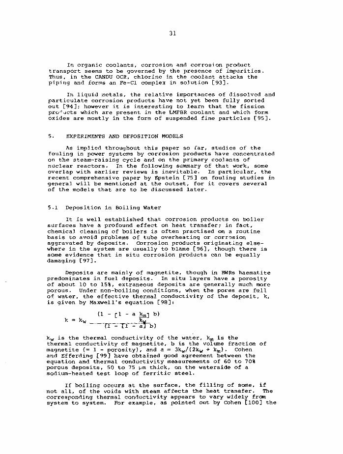
Deposits are mainly of magnetite, though in BWRs haematitepredominates in fuel deposits. In situ layers have a porosityof about 10 to 15%, extraneous deposits are generally much moreporous. Under non-boiling conditions, when the pores are fullof water, the effective thermal conductivity of the deposit, k,is given by Maxwell's equation [98]:
(1 - [1 - a 1^] b)
(1 - [1 - a3 b)
kw is the thermal conductivity of the water, km is thethermal conductivity of magnetite, b is the volume fraction ofmagnetite (= 1 - porosity), and a = 3kw/(2kw + k m ) . Cohenand Efferding [99] have obtained good agreement between theequation and thermal conductivity measurements of 60 to 70%porous deposits, 50 to 75 pm thick, on the waterside of asodium-heated test loop of ferritic steel.
If boiling occurs at the surface, the filling of some, ifnot all, of the voids with steam affects the heat transfer. Thecorresponding thermal conductivity appears to vary widely fromsystem to system. For example, as pointed out by Cohen [100] the
32
data for magnetite obtained by Macbeth [101] and Kelen andArvesen [102] were quite different, the former's being an orderof magnitude greater than the latter's. The main difference wasin the amount of evaporation and related heat transfer occurringwithin the deposit. Thus, Macbeth's system was such as topromote wick boiling [103] in which chimneys form within thedeposit and vent steam produced from the inward-seeping water.While steam chimneys have been observed in boiler deposits byother workers [104], they are clearly not always formed.Supercritical systems, as expected, do not have them [105].
Note that, as mentioned earlier, high concentrations of Cuin the corrosion product inventory can modify deposits andincrease their resistance to heat transfer. This occurredduring the early operation of the Steam Generating Heavy WaterReactor in England [106]. Then, high levels of Fe and Cu in thecoolant (several hundred yg/kg) resulted in thick (about 0.1 mm)deposits on fuel - particularly in regions of high heat flux.The copper made the deposits brittle and impervious, so that thevick-boiling mechanism described above could not operate. Waterpercolated through cracks in the deposit to the fuel elementsurface, but the steam could not escape easily and caused over-heating and subsequent deterioration and failure of the sheath.
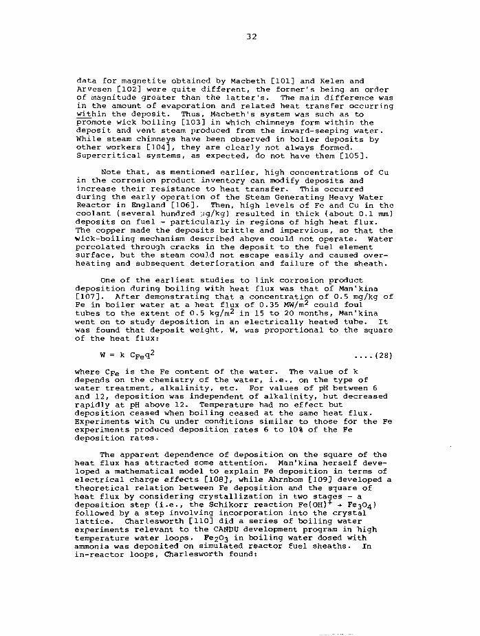
One of the earliest studies to link corrosion productdeposition during boiling with heat flux was that of Man'kina[107]. After demonstrating that a concentration of 0.5 mg/kg ofFe in boiler water at a heat flux of 0.35 MW/m2 could foultubes to the extent of 0.5 kg/m2 in 15 to 20 months, Man'kinawent on to study deposition in an electrically heated tube. Itwas found that deposit weight, W, was proportional to the squareof the heat flux:
W = k CFeq2 (28)
where Cpe is the Fe content of the water. The value of kdepends on the chemistry of the water, i.e., on the type ofwater treatment, alkalinity, etc. For values of pH between 6and 12, deposition was independent of alkalinity, but decreasedrapidly at pH above 12. Temperature had no effect butdeposition ceased when boiling ceased at the same heat flux.Experiments with Cu under conditions similar to those for the Feexperiments produced deposition rates 6 to 10% of the Fedeposition rates.
The apparent dependence of deposition on the square of theheat flux has attracted some attention. Man'kina herself deve-loped a mathematical model to explain Fe deposition in terms ofelectrical charge effects [108], while Ahrnbom [109] developed atheoretical relation between Fe deposition and the square ofheat flux by considering crystallization in two stages - adeposition step (i.e., the Schikorr reaction Fe(OH)+ •+ 3followed by a step involving incorporation into the crystallattice. Charlesworth [110] did a series of boiling waterexperiments relevant to the CANDU development program in hightemperature water loops. Fe2C>3 in boiling water dosed withammonia was deposited on simulated reactor fuel sheaths. Inin-reactor loops, Charlesworth found:
33
- the deposition was reversible,
- under constant conditions the amount of deposit reacheda steady value,
- the steady state was reached within a few days,
- the data was quite scattered, but the amount of depositwas proportional to the total iron concentration in thecoolant when the concentration was low and to the squareof the heat flux,
- the amount of deposit was not greatly influenced by thechemistry of the coolant or the mode of heat transfer(i.e., subcooled boiling or bulk boiling).
Additional experiments were done in an out-reactor loop inwhich fuel sheath surfaces were simulated by electrically heatedtest sections.
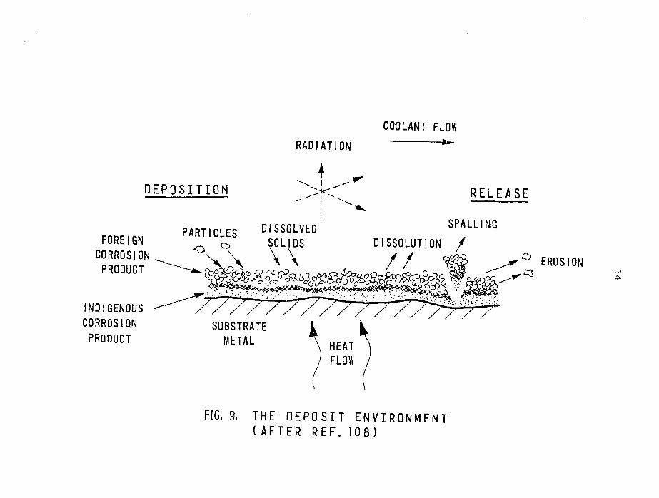
The accumulated data were incorporated in a mathematicalmodel of deposition in NH3~dosed boiling water based on theprocesses illustrated in Figure 9.
In the model the weight of deposited iron oxide, W, as afunction of time is given by
W = -1C (1 - e"k2fc) kg.cnr2 (29)k2
where C is the concentration of corrosion products in thecoolant, and the deposition rate constant, k^, is a functionof heat flux (Q/A W.cm"2) as follows
k]_ = 0.00025(Q/A)2 kg.cm-2.h-1 (30)
The value of the release rate constant, k2, was deduced froman in-reactor loop experiment to be about 0.01 h"1.
Note that there is evidence that the deposition of hardnesssalts also depends on the square of the heat flux. In experi-ments on the pool boiling of CaSC>4 solutions, Palen andWestwater [111] found that the amount of scale deposited waslinear with time - over short times - and proportional to thesquare of the heat flux.
During subcooled nucleate boiling, the heat flux supplyinglatent heat has an important effect on deposition [112]r infact, this was pointed out by Man'kina [107], but neither shenor Charlesworth included the effect in their equations.
Kot [113] has examined the deposition of various salts andcorrosion products (of Ca, Cu, Fe, etc.) onto stainless steeland Zircaloy surfaces under both bulk and subcooled boilingconditions. Heat fluxes were of the order of 1 to 1.5 MW/m2,and solids concentrations in the coolant ranged from 2.2 to 25mg/kg. In the subcooled boiling regime, deposits were heavieron Zircaloy than on stainless steel, and deposition was
COOLANT FLOW
RADIATION *"
DEPOSITION R E L E A S E
PARTICLES DISSOLVEDFOREIGN o SOLIDS
CORROSION ^ \. V \ \PRODUCT
INDIGENOUSCORROSIONPRODUCT
SPALLINGDISSOLUTION /
° EROSION
SUBSTRATEMETAL HEAT
FLOW
FIG. 9. THE D E P O S I T E N V I R O N M E N T(AFTER REF. 108)
35
inversely related to the amount of subcooling for all depositingspecies except Fe which showed no clear trend with subcooling.Ca and Cr concentrated at the inside of the deposits, while Mnand Cu concentrated at the outside; the other constituents werefairly evenly distributed.
Picone and Fletcher [114] attempted to correlate the depo-sition, W, with the corrosion product concentration, C, and thesubcooling, Tgat-Tbui^, by the following equation:
q.C.t* + C p (T s a t-T b u l k) ....(31)
where X is the latent heat and Cp the specific heat.Unfortunately, Equation 31 did not explain measurements of cruddeposits on fuel elements in the Saxton reactor - probablybecause of large changes in coolant chemistry during operationand shutdown. Kabanov [112] suggested that Equation 31 could beimproved by taking account of just the heat transferred aslatent heat, rather than the total heat flux.
Kot's experiments in the bulk boiling regime [113] showedthat deposition rates increased dramatically at the places onthe test sections where the liquid film left the surface anddispersed as drops; the drops apparently contacted the wall andevaporated completely. Deposition rates increased with increas-ing concentrations of corrosion products in the coolant. Copperwas found to plate out as metal in areas of high heat flux -largely in the outermost parts of the deposits, as mentionedbefore. A threshold heat flux for Cu deposition was found; thiswas postulated to be the minimum required to break down thecopper complex in solution. Above the minimum, the depositionrate, R, had a parabolic relationship with the heat flux:
R = k C^n q(q - qQ) ....(32)
in which qo is the minimum heat flux for Cu deposition and inthe exponent of the coolant concentration, CQU, n can bepositive or negative.
More recently, Thomas and Grigull [115] have reported theconclusions of a comprehensive study of magnetite deposition.Under non-boiling conditions, heat flux had very little effecton deposition, but turbulence was all-important. In nucleateboiling, the extra turbulence at the wall induced by bubbleformation increased deposition, so that there was an inverserelationship between subcooling and deposition. At saturatedconditions, deposition was linear with heat flux - not parabolicas reported elsewhere. In film boiling, transport of particlesto the wall was impeded and deposition rates were low. Theexplanation for measured decreasing rates of deposition withtime was that deposits smooth out roughnesses at the wall, andturbulence in the fluid-flow boundary layer decreasesaccordingly. This behaviour can be contrasted with that in astudy [2 5] in which iron corrosion products depositing duringboiling on stainless steel tubes caused an initial rapid
36
increase in pressure drop that subsequently levelled off at aconstant value,- the initial deposit apparently created a surfaceroughness that was not affected by later deposition.
Thomas and Grigull developed an empirical expression fordeposition based on the mass transport Stanton number, St' (St1
is the deposition velocity divided by the mean fluid velocity inthe channel). Semi-logarithmic plots of St' against the amountof deposit, W, gave a straight line; thus:
St1 = St'o exp(-W.b) (33)
which leads to a logarithmic equation for film growth. Theinitial deposition rate dW I was correlated with the
dt ' 0fluid flow as follows:
dW I 1.073
i.e., there is virtually a linear dependence of deposition rateon Reynolds number.
A more recent study on the depositon of iron corrosionproducts on heated Zircaloy was done by Asakura et al. [116] whoused electrically heated test sections at atmospheric pressure.They found a linear dependence of deposition rate on heat flux,q-
dW _ k.q.Cdt ~ X (35)
where C is the concentration of iron oxide suspended in thewater and X is the latent heat. The deposition constant, k,decreased as flow rate increased. By invoking a model ofevaporation and dryout of the microlayer of liquid beneath anucleating and growing bubble (as suggested by Hospeti andMesler [1173), they were able to evaluate k from firstprinciples and get good agreement with experimental values.
As the foregoing discussion implies, there have been manystudies of corrosion product deposition during boiling, yet thedetailed mechanisms are still not fully understood - especiallyat high temperature and pressure. The apparent dependence onheat flux - whatever the exponent - must be a secondary effect;bubble formation and the resulting fluid shear stresses atnuclei [118], evaporation, surface tension [119], particle-particle interactions, particle-surface interactions, andcrystallization are the principal effects that should beconsidered in developing a mechanistic model.
5.2 Deposition in Nuclear I.aactors - Activity Transport
It was realized quite early on in water reactor developmentprograms that out-core radiation fields would increase withoperating time. Corrosion products, released to the coolant by
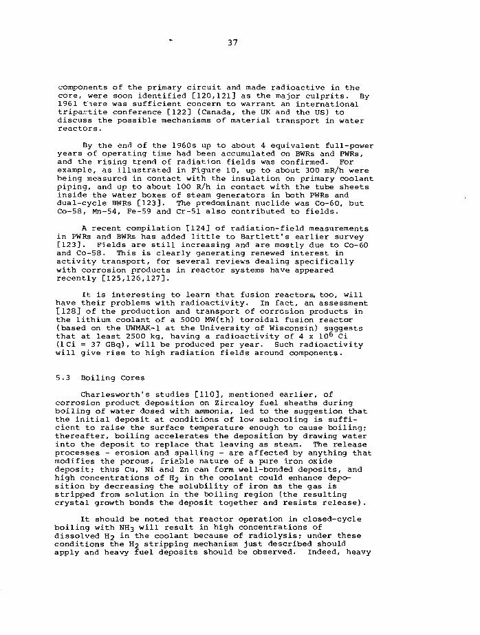
37
components of the primary circuit and made radioactive in thecore, were soon identified [120,121] as the major culprits. By1961 tiere was sufficient concern to warrant an internationaltripartite conference [122] (Canada, the UK and the US) todiscuss the possible mechanisms of material transport in waterreactors.
By the end of the 1960s up to about 4 equivalent full-poweryears of operating time had been accumulated on BWRs and PWRs,and the rising trend of radiation fields was confirmed. Forexample, as illustrated in Figure 10, up to about 300 mR/h werebeing measured in contact with the insulation on primary coolantpiping, and up to about 100 R/h in contact with the tube sheetsinside the water boxes of steam generators in both PWRs anddual-cycle BWRs [123]. The predominant nuclide was Co-60, butCo-58, Mn-54, Fe-59 and Cr-51 also contributed to fields.
A recent compilation [124] of radiation-field measurementsin PWRs and BWRs has added little to Bartlett's earlier survey[123]. Fields are still increasing and are mostly due to Co-60and Co-58. This is clearly generating renewed interest inactivity transport, for several reviews dealing specificallywith corrosion products in reactor systems have appearedrecently [125,126,127].
It is interesting to learn that fusion reactors, too, willhave their problems with radioactivity. In fact, an assessment[128] of the production and transport of corrosion products inthe lithium coolant of a 5000 MW(th) toroidal fusion reactor(based on the UWMAK-1 at the University of Wisconsin) suggeststhat at least 2500 kg, having a radioactivity of 4 x 10⁶ Ci(ICi = 37 GBq), will be produced per year. Such radioactivitywill give rise to high radiation fields around components.
5.3 Boiling Cores
Charlesworth1s studies [110], mentioned earlier, ofcorrosion product deposition on Zircaloy fuel sheaths duringboiling of water dosed with ammonia, led to the suggestion thatthe initial deposit at conditions of low subcooling is suffi-cient to raise the surface temperature enough to cause boiling;thereafter, boiling accelerates the deposition by drawing waterinto the deposit to replace that leaving as steam. The releaseprocesses - erosion and spalling - are affected by anything thatmodifies the porous, friable nature of a pure iron oxidedeposit; thus Cu, Ni and Zn can form well-bonded deposits, andhigh concentrations of f?2 in the coolant could enhance depo-sition by decreasing the solubility of iron as the gas isstripped from solution in the boiling region (the resultingcrystal growth bonds the deposit together and resists release).
It should be noted that reactor operation in closed-cycleboiling with NH3 will result in high concentrations ofdissolved Hj in the coolant because of radiolysis; under theseconditions the H2 stripping mechanism just described shouldapply and heavy fuel deposits should be observed. Indeed, heavy
at
o_ JLU
I-H
a
as
1000
r 100 —
10 -
i -
0 . 1 -
o . o io
\ V
x \ \ N \ \ STEAM GENERATOR TUBE' "x v SHEET ( I N C L U D I N G DUAL-
CYC" E BWRs)
r - r : ^ r N INSULATION ON^ P R I M A R Y COOLANT
PIPING
2 4 6 8E Q U I V A L E N T F U L L POWER YEARS
10 12
F I G . 1 0 . R A D I A T I O N F I E L D S O N B W R s A N D P W R s ( A F T E R R E F . 1 2 1 )
39
fuel deposits have been generally obtained during closed-cycleboiling with NH3. Quite recently, however, Burrill added bothLiOH and NH3 to the coolant in the X-3 loop of the NRX reactorduring a boiling experiment and found only thin deposits [129].This indicates that H2 stripping is not responsible and thatalkalinity is; in fact, the explanation is based on solubilitydifferences induced by alkalinity gradients. Thus, particles ofcrud (corrosion product) are deposited on fuel sheaths by hydro-dynamic and electrostatic effects and are irradiated. InNH3~dosed water at reactor conditions, where the solubility ofcrud (assumed to behave like magnetite) decreases with alka-linity, evaporation at the heated surface raises the pH locallyand enhances the deposition by the precipitation of magnetite;there is no driving force for release other than a slight amountof erosion and deposits are consequently thick. As the H2concentration increases the crud solubility gradient becomessteeper and even thicker deposits are obtained in closed-cycleboiling water with NH3. With the added LiOH the solubility ofcrud at reactor temperature increases with alkalinity, so disso-lution enhances release and ieads to thin deposits [129,130].
Later tests [131D with high concentrations of ammonia alsoproduced thin deposits on fuel, leading to the suggestion thatNH4OH can be concentrated in water at a boiling surface,though not so readily as a solid hydroxide such as LiOH. Inaddition to concluding that alkalinity is the principal variableaffecting fuel deposits in boiling water, Burrill summarizes[131] his findings as follows:
- crud concentration in the coolant has little effect ondeposition,
- apart from its effect in closed-cycle boiling withammonia, hydrogen has little influence on the formationof fuel deposits,
- deposit weight increases with heat flux, but is affectedlittle by reactor irradiation.
In brief, the mechanism by which deposits form on reactorfuel are postulated [132] to be as follows. Crud particlesdeposit initia]_y, then deposition is enhanced by the filtrationof particles f om the water percolating through the deposit tosteam nucleation sites. Release occurs by dissolution if thealkalinity is high enough, and by spalling if it is not.Spalling may be brought on when the deposit thickness andporosity restrict water flow to active nucleation sites andcause bubbles to form elsewhere in the deposit. Those bubblesbreak away pieces of the deposit above them. Measurements ofdeposits on fuel from a CANDU reactor operating with boilinglight water as the coolant can be explained by these mechanisms[132].
40
5.4 Non-Boiling Cores
In the early days of nuclear reactor development it wasrecognized that in pressurized water operation crud concentra-tions and deposits on fuel are kept low if the coolant pH (asmeasured at room temperature) is maintained above 10 or so[33,133]. Loop experiments in experimental reactors demonstra-ted the effect quite clearly [134]. Not only is alkalinity thedominant variable in determining fuel deposits - as in boilingwater operation - but also the actual pH additive appears tohave little effect [131]. Again, as he did for boiling wateroperation, Burrill [131] concluded that neither dissolvedhydrogen nor crud concentration in the coolant affects depositweights. When deposits are thick (greater than 1 g Fe/m^),they seem to increase with increasing heat flux; thin depositshave no clear dependence on heat flux.
Burrill's mathematical model [135] for deposition on fuelsheaths assumes that the crud behaves as magnetite, that itsdeposition rate, r, is proportional to its concentration in thecoolant (i.e., r = kC where k is the deposition rate constant ofparticles), and that its dissolution release rate afterdeposition is proportional to the undersaturation in the coolantS-c. Here S is the solubility at the sheath temperature and cis the dissolved iron concentration. The deposit weight, W, isthen given by:
W =
where a is the specific surface area of the deposit and 6 is thedissolution rate constant. The form of Equation 36 is theasymptotic approach to equilibrium which is by now quite commonin the fouling literature. It is identical with the form ofCharlesworth's [110] equation (Equation 29) for deposits inboiling; only the concepts behind the deposition and releaseterms are different.
Note that the residence time, T, is a measure of how longan atom of crud remains in the core. It is given by:
T =a(3(S-c) (37)
Residence times can be estimated from measurements of thespecific radioactivity (activity per unit mass) of crud removedfrom irradiated fuel. They usually fall within the range of afew days to a few weeks. Experimental fuel is generallyirradiated for periods of a few weeks to months; commercial fuelstays in the reactor for a year or so. Thus, measured fueldeposits are at the steady state, and kinetic information is notavailable. Given that limitation. Equation 36 agrees reasonablywell with measurements of deposits on experimental fuelirradiated in loops in an experimental reactor and withmeasurements of deposits on CANDU fuel bundles [135].
41
The model has also been made the basis of a theory forradiation field growth in PWRs [136]. In this case, changingchemistry throughout a reactor cycle has to be accounted for.At the beginning, the coolant alkalinity is low because of theboric acid poison in the coolant, and corrosion product solubi-lity is such as to cause precipitation on the fuel; at the end,the poison has been consumed and the high alkalinity promotesdissolution off the fuel. The final fuel deposits are thereforefunctions of the boric acid and lithium hydroxide concentrationsthroughout the cycle, as well as of operating parameters such astemperature, heat flux, and the number of shutdowns. Solomonand Roesmer [137] have attempted to factor such parameters intoan explanation of observed amounts of fuel deposits and radia-tion fields at eight operating PWRs. Though the agreement oftheir theory with observation was encouraging, it was concludedthat more detailed measurements of concentrations of corrosionproducts as particles, colloids and solubles are required fromoperating plants, as well as more fundamental information oncrud solubilities and dissolution rates from researchers, beforea comprehensive model can be formulated.
One way of obtaining kinetic data is to simulate a fuelelement surface in a laboratory and to measure corrosionproducts as they deposit. This has been done in a loopoperating with lithiated pressurized water at very low crudlevels (approximately 0.1 yg/kg). The deposition of Co-60 fromsolution was measured continuously with a gamma spectrometer.The main conclusion of the study [138] is that at low crudlevels in power reactors, adsorption of dissolved cobalt ontofuel sheaths could be a significant source of Co-60. Concomi-tant desorption supplies radioactivity to be distributed aroundthe system and gives rise to radiation fields. The presence orabsence of heat flux has no measurable effect on the process.
In organic-cooled reactors fouling films can have seriousconsequences for in-core heat transfer. For example, permittingan annual increase in fuel sheath temperature of 25°C meansrestricting the fouling rate to 2 mg/(m2.h). This corresponds,for a typical fouling film, to an increase in thickness of about10 um in a year.
Experiments done by Campbell et al. [93] on the fouling ofsurfaces cooled with organics have led to postulates of twotypes of mechanism that operate in the core of the CANDU-OCR.
The first mechanism involves the transport and depositionof organic particles. It is apparently controlled by a surfacereaction; the fouling rate doubles for a surface temperatureincreas of 30°C, and deposition is unaffected by impuritiessuch ai> CI2, H2O or 03 in the coolant.
42
The second mechanism is mass transfer controlled andinvolves a reaction between CI2 impurity in the coolant andiron of system surfaces. An Fe-Cl complex is formed; this istransported to the core where it breaks down on the hot fuelsheaths depositing iron and iron oxides, the CI2 thereby beingreleased to carry on the process. The deposition rate doubleswith a sheath temperature increase of 25 to 70"C and is propor-tional to the coolant velocity to the power 0.5 to 1.0. Otherimpurities such as O2 and H2O do not promote fouling and canbe added as needed to maintain protective films on componentsurfaces. The acceptable fouling rate quoted above can beachieved by keeping the CI2 concentration below about 3 mg/kg- a level which will not promote excessive hydriding ofzirconium alloys in the core.
Bogdanov [139] postulated that the same two mechanismsoccur in the Russian Arbus reactor, but added a third.Radiation and thermal degradation of the coolant apparently ledto a buildup of low boiling fractions, and boiling at the sheathsurfaces was promoted. The evaporation led to a concentrationof particles in the coolant next to the surface, and depositionwas enhanced.
Nijsing [140] has developed equations to describe thesemolecular and particulate mechanisms in organic fouling. Theyare based on the concept of transport with chemical reaction.For the conditions of Campbell's experiments, his prediction ofa fouling rate of 1.8 g/(m2.h) is in reasonable accord withthe measured value of 1.1 g/(m2.h).
5.5 Out-Core Components
The out-core piping and steam generators are contaminatedby the radioactivity transported out of the core by the coolant.Note that, as mentioned earlier, a particularly troublesomeradionuclide in reactor circuits is Co-60. It is formed by theirradiaton in-core of its parent, Co-59, which has a high crosssection for neutron capture and is the only natural isotope ofcobalt. Furthermore, Co-60 has a long half-life (5.2 years) andemits very penetrating gamma rays as it decays; therefore, evensmall quantities of cobalt in a reactor circuit can cause highradiation fields. Generally, materials containing a lot ofcobalt are excluded as much as possible from reactor circuits,though the hardness of some cobalt alloys makes them essentialfor some applications where wear resistance is required. Steelsand nickel alloys contain cobalt as an impurity, but the extentto which the cobalt content can be reduced will depend on thecost; the savings in radiation dose gained by specifyinglow cobalt materials may not always be worth the extra price.In PWRs, Co-58 also can give problems. It is formed by a fast-neutron reaction with naturally occurring Ni-58, and has a half-life of 70.8 days - long enough to be a nuisance.
43
As the oxide films grow on system surfaces because ofcorrosion, corrosion product ions from elsewhere in the circuitcan become incorporated in the crystal lattices of those oxides.If some of the ions are radioactive, then incorporation willcontaminate the whole oxide layer and therefore the surface.The rate of contamination will be governed by the growth of thefilm which, in turn, is governed by the corrosion of the basemetal. On heat transfer surfaces, of course, film growth alsodepends on the temperature gradient in the coolant and thesolubility of the dissolved corrosion products; for example, inCANDU boilers where the high pH coolant is cooled from about290°C to about 250°C, magnetite can precipitate and incorporateradioactivity in its crystal structure as it does so. Cobaltions in particular should be incorporated easily in surfacefilms. Note that the surface radioactivity is effectively fixedin the oxide layer. This means that decontamination by inactivecoolant proceeds via solid-state diffusion out of the oxidecrystals (except for a slight amount of erosion); in fact, suchdecontamination has been found to occur at a rate apparentlycontrolled by solid-state diffusion [141].
Experiments [91,92] have established such a link betweensurface fouling by radioactive corrosion products and thecorrosion of the underlying metal, and a mathematicaldescription of the mechanisms applicable to carbon steel andstainless steel has been developed [141].
For a radioactively decaying concentration of dissolvedradioactive corrosion product (C-̂ ° e~'lt) at the entranceto a pipe (as frequently occurs in laboratory experiments [92]),the contamination of the pipe surface corrected for decay(C*w(x,t)) can be expressed [90] as
t
J o
t - 1* (t)n(t)e
d u ' n .at ....(38)
where n(t) is the surface activation coefficient which reflectsthe material's affinity for radioactivity, d is the pipediameter and u is the coolant velocity.
Several terms incorporating corrosion parameters and theproperties of the oxide film are contained in n (t) . Thus:
n(t) =l 1
'39)1h 1
DIFFn +
1+
CRYSTi1
CRYSTO
where DIFFi is the diffusional resistance to transport throughthe inner layer of oxide and CRYSTi and CRYSTO are thecrystallization or incorporation resistances of the inner andouter layers respectively. As mentioned earlier, the surfaceprocesses generally control, so the mass transfer resistance inthe liquid film, l/h where h is the mass transfer coefficient,can be neglected. When the various surface transportresistances are related to corrosion rate and oxide properties,the model agrees well with experimental data.
44
If, as in the steam generators, the corroding surface iscooled, there will be an extra driving force at high pH for theprecipitation of an outer oxide layer. On boiler tubes ofnickel alloys (which generally form just a single layercorrosion film under isothermal conditions) this will be theonly mechanism of formation of an outer layer; on stainlesssteel tubes it will add to the outer layer formed by normallocal corrosion.
The inner layer will incorporate radioactivity by the samemechanism as the inner layer on isothermal steels; the outerlayer incorporation will be via a crystallization mechanism -again analogous to that on isothermal steels but with adifferent primary driving force. The mathematical description,developed from out-reactor loop studies on simulated boilertubes of Inconel [142] and Incoloy [143], reflects the simila-rity of the isothermal and the cooled processes. The differenceappears mainly in the CRYSTO term in Equation 39; that termnow has to account for oxide precipitation by the solubilitydecrease due to cooling.
An interesting extension of the incorporation theory hasconsidered [144] the possibility that the coolant leaving thecore of a CANDU reactor might be undersaturated with respect toFe. That would mean that the magnetite film on the steelsurfaces of the reactor outlet pipes is thinner than that on theinlet pipes. The resulting differences in corrosion rates andcontamination levels, however, are predicted to be small.
A similar concept for the incorporation of radioactivecorrosion products in growing oxide films has recently beendevised by DeHollander [145]. The main difference is that afixed number of sites for incorporation of radioactive ions in agiven amount of oxide film are postulated. In other words, forcontamination by Co-60 or Co-58, the Co/Fe ratio is fixed in thespinel oxide, and radioactive cobalt is taken up by sites inproportion to its concentration in the coolant. The model hasbeen proposed for application to BWR piping.
5.6 Whole System
The traditional method of extrapolating measured trends inactivity transport in water-cooled reactors has employedmathematical models containing first order empirical coeffi-cients. The coolant circuit to be modelled is divided intoappropriate components (in-core surfaces, out-core surfaces,bulk coolant, crud, and so on) and the exchange rates ofradionuclides between the components are represented by theproducts of the coefficients (assumed constant) and theappropriate concentrations.
45
A simple illustration is the two-component model comprisingexchange between a coolant and a pipe wall. If the bulk coolantconcentration of radionuclide is constant, Cj-,, the concentra-tion on the wall, Cw, as a function of time, t, is given by:
ad . Cb . (1 - e -(b+A)t) ....(40)
where a and b are the deposition and release coefficientrespectively, d is the pipe diameter, and A is the radioactivedecay constant. Equation 40 is the familiar exponentialapproach to equilibrium, when:
C w <-> = 4 7 ^ - * C b ....(41)
More complicated solutions are available [92] for the casewhere the bulk concentration, Cj,, is a variable and concentra-tions vary with distance along the pipe.
One of the most comprehensive applications of first-orderexchange or transport coefficients to a full system was that ofYerazunis et al. [146]. They divided a reactor circuit into ninenodes - solubles in coolant, particles in coolant, transientout-core crud, permanent out-core crud, transient in-core crud,permanent in-core crud, crud traps, purification system and corestructural components. The possible exchange mechanisms betweennodes are particle and molecular transport, recoil and"particulation" (precipitation of solubles), each being describedby a differential equation. The resulting set of equations islarge, so fitting them to data from an operating system is aconsiderable task - even with a computer.
Walton [147,148] has described exchange mechanisms bysimilar equations involving first-order coefficients. The fitof the model to data from experimental loops was good, andfurnished deposition and release coefficients for variousradionuclides at surfaces.
Walton's coefficients have since been used in a systemmodel to determine the effectiveness of a purification circuitin controlling the concentrations of radioactive corrosionproducts in a PWR [149]. It was concluded that even with apurification half-life of about 2 hours there would be asignificant effect on the resulting asymptotic activity levelreached after about 3 years. Nowadays, keeping crud levels lowand the core clean, rather than removing already-producedradioactivity, is considered to be the best way of controllingactivity transport. To that end, the latest CANDU reactors haveeither high temperature filters or high capacity purificationcircuits to remove crud with a minimum clean-up half-life of 20minutes [150].
46
Epstein and Evans [151] developed analytical equations inwhich the coefficients described processes such as adsorptionand desorption, and in which mass transfer and fluid flow areaccounted for. Bonalumi and Olivi [152] wrote general equationsfor describing activity transport in idealized coolant channelsin terms of coefficients that were functions of the physical andchemical parameters of the system and that would have to bedetermined in any application of the model to an operatingsystem. Their approach was similar to the later one of Clement[153] whose equations specifically took account of mechanismssuch as molecular diffusion and mass transport, and particlegrowth and dissolution, in describing a non-isothermal circuit.
Recent theoretical treatments using first-order transportcoefficients have examined the effects on surface activity ofremoving the source term from the bulk coolant [154] and havegone a stage beyond surface activation by employing shieldingcalculations to predict resulting radiation fields [155]. Theempirical approach of Cunnane et al. [156] optimized phenomeno-'logical coefficients by fitting equations to data from PWRs ;agreement with a similar formulation, in which the coefficientswere replaced with constants that described the mechanisms, wasgood.
A mechanistic model, of course, can be applied withconfidence to different systems; an empirical model, thoughuseful for characterizing or extrapolating trends, is usuallyrestricted to the system for which it was devised. Hence, therehave been efforts to describe whole system contamination on thebasis of experimentally established mechanisms.
As Bartlett has pointed out [157], the number of mechanismsthat might have to be considered in describing a reactor islarge. Generally, however, only a few - or perhaps even one -can be considered as controlling, as we found in the discussionsof separate in-core and out-core mechanisms.
That oxide solubility is one such controlling mechanism isclear; it is important both in the core and out. The PACTOLEcode of Frejaville and co-workers [47] for describing activitytransport throughout PWR systems considers temperature changesaround the coolant circuit and allows oxide films to dissolve orparticles to precipitate homogeneously as the correspondingsolubility change dictates. The particles deposit according tothe mechanism formulated by Beal [45]. Although the concept ofhomogeneous nucleation in a system that must abound with crystalnuclei on the walls seems unrealistic, the code has predictedactivity transport in a PWR very well [158].
Particle transport and deposition are obviously importanttoo, even though the way crud is formed is still not fullyunderstood. In a BWR, much of the iron oxide enters the coresystem with the feedwater, though erosion and spalling offsystem surfaces must play a part. The contamination model ofUchida et al. [159] considers crud to deposit on BWR fuelaccording to the microlayer evaporation and dry out model ofAsakura et al. [116]. Cobalt ions adsorb on the crud deposits,and Co-60 is released as crud is released from the fuel. The
47
model has been simplified and made empirical to evaluate theeffects on activity transport of several proposed modificationsto an operating BWR [160].
One aspect of the transport of corrosion product particles,which Gasparini et al. [161] considered important for the wholesystem activation, is the electrokinetic effect - the chargeacquired by particles in the reactor coolant. It was postulatedthat the electrostatic forces between crud particles andsurfaces are the principal factors affecting deposition and thatalternate layers of positively and negatively charged particlescould be laid down (by contrast, Burrill [162] found fromlaboratory experiments below about 90°C that pH - and thereforeelectrokinetic effects - had only a small influence on thedeposition of magnetite onto various surfaces). Since nickelferrite is at its point of zero charge in the neutral water of aBWR - in contrast to the normal iron-rich corrosion product - itwas argued that promoting nickel ferrite formation in BWRs wouldhinder particle deposition and control activity transport. Theeffect was demonstrated by injecting nickel hydroxide in thefeedwater of a BWR, when a net removal of crud - mainly asnickel ferrite - occurred.
However, although Nicholson [163] demonstrated a similareffect in a laboratory loop, it was small and indicated thatincreased deposits might result from the general addition ofnickel hydroxide to BWRs.
The first studies of corrosion products relevant to theLMFBR reported on small-scale experiments and on attempts toextrapolate results to larger systems such as the FFTF (FastFlux Test Facility) [164] or the full-scale reactor. Thus up to1969, the effects of intensive system variables such as tempera-ture, temperature difference, flow rate, levels of oxygenimpurity and materials had been looked at, but little was knownabout the effects of extensive variables such as surface/volumeratios or recycle time [165].
An early mathematical model [166] considered two alterna-tive controlling mechanisms for liquid metals - transport in theliquid and dissolution rate. Both particulate and dissolvedmaterial, however, seem to be important. Temperature diffe-rences lead to rapid transport of Mn-54, Co-58 and Co-60 to coolsurfaces in systems containing radioactive corrosion products[167]. Deposits in the cold leg of the Harwell loop were porousand spongy and composed mostly of the pure metals Fe and Cr,particles rich in Fe-Cr and Si-Ca, and mixed carbides and oxidessuch as sodium ferrate or chromite. Particle sizes weregenerally less than 10 jjm [167]. Also, loop tests haveindicated [168] that in 40 years a reactor system could accumu-late deposits amounting to several tons in the intermediate heatexchanger. The heat transfer coefficient would be reduced byabout 15% - necessitating extra capacity or the ability to raisethe primary coolant temperature - and high fields would causeproblems of radiation exposure during cleaning and maintenance.
48
On hot surfaces, particles of sodium chromite and whiskersof alpha-Fe have been found [168,169], the former particularlyon Cr-containing alloys. Observations such as these indicatethat there must be some contribution from dissolved species tothe overall transport, but often it is difficult to tell whethercorrosion products have been transported as particles or asdissolved species [94].
In predicting the activity produced in a large-scalesystem, Merkel and Menken [170] assumed a uniform corrosion rateof component alloys and a release of elements proportional totheir concentration in the metal. The release rate depends onthe oxygen level in the sodium; below a linear velocity of 3 m/sit is proportional to velocity, above that velocity it isconstant. An equilibrium inventory of Co-58, Co-60 and Mn-54 of2000 Ci was predicted, giving rise to fields of about 1 R/h onthe main pipes and several R/h near the pumps and heatexchangers.
Polley [171] presented a mathematical analysis of thedetailed corrosion processes of alloy surfaces in contact withflowing sodium. The equations describe the concentrations ofmetallic components in the alloy and in the sodium around thecircuit; because the outer layers of the alloy are progressivelyaffected, the mathematical solutions involve moving boundaries.Final expressions then give the asymptotic concentrationprofiles of species in austenitic stainless steel with a ferritesurface layer.
Recently, reference has been made [172] to a computer code,CORONA, which predicts corrosion product transport in a LMFBR.Considering Mn-54 as the predominant radionuclide (it willcomprise 90% of circuit activity after 20 years) and using datafrom the Rapsodie and Phenix reactors, the code predicts anequilibrium inventory of 1120 Ci for a 1200 MW reactor.
5.7 Deposition in Condensers
The principal cause of loss of heat transfer in condensersis fouling on the cooling-water side. Four types of foulingfilm can occur [173] - precipitation of hardness salts such assulphates or carbonates from fresh water, deposition ofsuspended solids such as silt or sand, growth of organisms suchas barnacles in sea water, and development of corrosion productfilms. Note that the first three affect heat transfer and canpromote local corrosion such as pitting in stainless steel andcopper alloys. Corrosion products, on the other hand, havelittle effect on heat transfer; they can, however, protectagainst corrosion and inhibit biological fouling, depending onthe metal of the condenser tube.
In a recent survey [174] of condenser performance in seawater service, 70/30 cupronickel was identified as the copperalloy having the best corrosion resistance, 90/10 cupronickelwas next, Al brass was next, and Admiralty brass was the worst -chiefly because of its susceptibility to impingement corrosion.Titanium has excellent corrosion resistance in sea water, thoughit is expensive and can be prone to vibration failure.
49
Stainless steel performs well in fresh water, but in brackish orsea water it tends to pit under deposits or under low flow orstagnant conditions.
The performance of copper alloys can be improved byinducing a corrosion product layer rich in Fe to form on thetube surfaces. Fe in Al bronzes or in Cu-Ni alloys will helpprotective films to form if it is in solid solution. Theprotection seems to be given by a thin, crystalline film ofCU2O incorporating hydrated ferric oxide. If enough Fe ispresent to form a separate phase in the alloy, a non-protectivefilm of Fe3C>4 and CU2O is formed [175].
The corrosion of brasses is not affected by the incorpo-ration of Fe in the alloy. Then, Fe is introduced into thecooling water itself - either by using sacrificial metal blocksor by periodic or continuous injections of FeSO.4.
The nature of the resulting protective film depends on thealloy, but lepidocrocite (gamma-FeOOH) seems to be an importantconstituent [176]. Castle et al. [177] believe that protectionis conferred by a corrosion product having the formulaNaCuFejOj^o- They found that the compound covered about 20% ofthe surfaces of Al-brass condenser tubes that had been in seawater service for up to 20,000 hours with concentrations ofFeSC>4 of 1 mg/kg maintained for two periods of 1 hour everyweek.
A mechanism for the formation of protective lepidocrocitefilms was propounded by Gasparini et al. [178]. The hydrolysisand oxidation of FeSC>4 in demineralized aqueous solutioncauses Fe{OH)3 to precipitate and the pH to fall. In naturalcooling waters, oxidation should be faster, and the pH higher,than in a laboratory environment because of buffering bybicarbonates. It was postulated that the colloid formed isactually lepidocrocite, because it has the correct point of zerocharge and because it has been seen on surfaces.
At concentrations of FeSC>4 in the mg/kg range, thelepidocrocite particles are negatively charged at the resultingsolution pH. The CU2O corrosion product film on the condensertubes, however, is positively charged, and the electric fieldextends well into the bulk of the solution because counterionsare swept away by the high velocity coolant. FeOOH particles,therefore, are attracted to the surface and stick there.
The study also indicated that concentrations of FeSC>4below 0.5 mg/kg might be sufficient to maintain satisfactoryprotection.
And, finally, corrosion product films have an importantinfluence on biological fouling. Such fouling is critical insea water, and seems to bear a relationship to the type ofcorrosion film on the underlying metals [179]. Marine organismsgrow readily on corrodible metals such as steel, though thefouling can be removed easily, and often spalls off itself withthe loose corrosion product. Passive materials such as Al or Tifoul readily to give a tightly adherent layer. Pressure dropand heat transfer are affected and localized corrosion can occurif the metal is sensitive to O2 concentration cells.
50
Alloys based on Cu, however, are resistant to such fouling.Apparently, the corrosion product film of CU2O is toxic tomost organisms. That it is not Cu in solution at the surfacethat inhibits fouling is demonstrated by the fact that differentmaterials immediately adjacent are unaffected. Rathersurprisingly, other metals such as Be or Pb that might beexpected to form toxic corrosion product films do not do so, andfoul readily.
6. SUMMARY AND CONCLUSIONS
The important mechanisms of corrosion and fouling infossil-fired and nuclear power stations have been reviewed; itis clear that even when not causing fouling problems directlycorrosion interacts with most of the other fouling mechanisms.
On the fireside of fossil-fuelled boilers, where depositscan impede heat transfer and diminish performance and canaggravate tube corrosion, the overall processes of fouling areaffected little by corrosion products or by the corrosionprocess itself.
On the waterside, however, corrosion films can have seriousconsequences, for impairment of heat transfer can lead to tubeoverheating and eventually to catastrophic failure. Sometimes,indigenous corrosion films are important; for example, they canseriously impede heat transfer in superheater or reheater tubes,and can cause excessive pressure drop and flow distributionproblems in once-through boilers. Corrosion products carriedinto the boiler by the feedwater and deposited as particlescontribute to the general fouling - particularly if they containelements such as copper which destroy the porous structure ofdeposits and thereby interfere with boiling heat transfer.
In the cores of water-cooled reactors, thick deposits ofcorrosion products can lead to fuel overheating and sheathrupture; deposition may be by particulate or precipitationmechanisms. Even thin deposits that do not affect heat transferadversely (they can even enhance it by comparison with thebehaviour of smooth surfaces) cause problems of radioactivecontamination of out-core components.
Such radioactive "fouling" is itself intimately linked withthe corrosion of the primary-side surfaces of the components.On isothermal piping, for example, local corrosion controls thedeposition of radioactive corrosion products that must originatein the core. On the other hand, in the boilers ofindirect-cycle reactors, local corrosion plays a secondary roleto that of solubility gradients - corrosion products originatingelsewhere are precipitated by cooling if the alkalinity ishigh.
51
On the secondary side of nuclear boilers loss of heattransfer is not a serious problem, for extra capacity isavailable and the tube wall temperature cannot rise above theprimary-coolant temperature. Rather, fouling by corrosionproducts and other materials entering with the feedwater cancreate areas where aggressive chemicals can concentrate andwhere local corrosion can result.
In organic-cooled reactors, corrosion mechanisms interactwith chemical reaction mechanisms to foul fuel sheaths. Thus,complexes of corrosion products and impurities such as chlorineare broken down at the hot surfaces; corrosion products depositand can cause sheath overheating, while the impurities arerecycled to complex more corrosion products.
In liquid-metal-cooled reactors, corrosion productdistribution can lead to fouling of surfaces and to radioactivecontamination of components. Both particles and dissolvedmaterial are transported and deposited, v/ith the composition ofthe underlying metal having some influence on the structure ofthe deposit.
In condensers, the corrosion films on the cooling waterside of the tubes have important influences on corrosionmechanisms and fouling. In brass condensers, iron corrosionproducts may be introduced into the cooling water stream andinduced to deposit on the tubes as a protective film. Also, thegrowth of the indigenous corrosion film interacts strongly withbiological fouling. Thus, the copper oxide film on copper-bearing alloys inhibits fouling by marine organisms, presumablybecause of the toxicity of the solid oxide itself.
7. ACKNOWLEDGEMENT
This review was made possible by the efforts of the librarystaff at Chalk River Nuclear Laboratories who are hereby thanked.In particular, O.S. Tatone is thanked for contributing to theliterature search, and R.H. Campbell for collecting and sortingthe references. Valuable discussions with S.F. Featherby of theThermal Generation Division of Ontario Hydro and with K.A. Burrillare acknowledged, and Donna Cole is thanked for her diligence intyping the manuscript.
8. REFERENCES
1. L.H. Bennett, J. Kruger, R.L. Parker, E. Passaglia,C. Reimann, A.W. Ruff H. Yakowitz and E.B. Bennan, "Economiceffects of metallic corrosin in the United States, Part 1",NBS Special Publication 511-1, May 1978.
2. R.C. Corey, B.J. Cross and W.T. Reid, "External corrosionof furnace-wall tubes. II Significance of sulphatedeposits and sulphur trioxide in corrosion mechanism",Trans. ASME, 1945, 67 (4), 289.
52
3. P.G. Ely and L.B. Schueler, "Distribution of heatabsorption and factors affecting performance of twin branch2500 psi boiler", Furn. Perf. Factors Suppl. to Trans.ASME, 1944, 6^, 23.
4. W.T. Reid, "External corrosion and deposits: boilers andgas turbines", American Elsevier Publ. Co., Inc., New York,1971.
5. E.P. Dirk, V.D. Surovitskii, A.N. Soboleva and Yu.Ya.Kuskova, "Formation of deposits with high concentration ofiron oxides on boiler heating surfaces", Teploenergetika,1977, 24 (9), 51.
6. W.D. Halstead, "A review of saturated vapour pressures andallied data for the principal corrosion products of iron,chromium, nickel and cobalt in flue gases", Corrosion Sci.,1975, 1_5 (10), 603.
7. H.H. Uhlig, "Corrosion Handbook", John Wiley and Sons,Inc., 1948.
8. E.C. Potter and G.M.W. Mann, "Oxidation of mild steel inhigh-temperature aqueous systems", Proc. 1st Intern. Cong.Metallic Corrosion, p. 417, London, (1961).
9. J.E. Castle and H.G. Masterson, "The role of diffusion inthe oxidation of mild steel in high temperature aqueoussolutions". Corrosion Sci., 1966, 6, 93.
10. G.J. Bignold, R. Garnsey and G.M.W. Mann, "High temperatureaqueous corrosion of iron. Development of theories ofequilibrium solution phase transport through a porousoxide", Corrosion Sci., 1972, Ij2, 325.
11. D.L., Douglas and F.C. Zyzes, "The corrosion of iron inhigh temperature water. Part 1 - Corrosion ratemeasurements". Corrosion, 1957, _1^, 361t.
12. D.L. Douglas and F.C. Zyzes, "The corrosion of iron in hightemperature water. Part 2 - Kirkendall experiments",Corrosion, 1957, 1̂ 3, 433t.
13. M.C. Bloom, "A survey of steel corrosion mechanismspertinent to steam power generation", 21st Annual WaterConf., Engineering Soc. of Western Pennsylvania, Pittsburg,Pennsylvania (Oct. 1960).
14. J.B. Moore, Jr. and R.L. Jones, "Growth characteristics ofiron oxide films generated in dilute LiOH solution at300°C", J. Electrochem. Soc., 1968, 115 (6), 576.
15. U.R. Evans, "The oxidation of metals". Rev. Pure and Appl.Chem., 1955, 5 (1), 1.
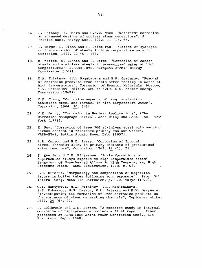
53
16. R. Garnsey, B. Hearn and G.M.W. Mann, "Waterside corrosionin advanced designs of nuclear steam generators", J.British Nucl. Energy Soc., 1972, 1^ (1), 65.
17. P. Berge, C. Ribon and P. Saint-Paul, "Effect of hydrogenon the corrosion of steels in high temperature water".Corrosion, 1977, ̂ 1 (5), 173.
18. M. Warzee, C. Sonnen and P. Berge, "Corrosion of carbonsteels and stainless steels in pressurized water at hightemperatures", EURAEC 1896, European Atomic EnergyCommission (1967).
19. M.A. Tolstaya, S.V. Bogatyreva and G.N. Gradusov, "Removalof corrosion products from steels after testing in water athigh temperatures". Corrosion of Reactor Materials, Moscow,V.V. Gerasimov, Editor, AEC-tr-5219, U.S. Atomic EnergyCommission (1969).
20. C.F. Cheng, "Corrosion aspects of iron, austeniticstainless steel and Inconel in high temperature water",Corrosion, 1964, ̂ 0, 341t.
21. W.E. Berry, "Corrosion in Nuclear Applications", (TheCorrosion Monograph Series), John Wiley and Sons, Inc., NewYork (1971).
22. E. Rau, "Corrosion of type 304 stainless steel with varyingcarbon content in reference primary coolant water",WAPD-BT-3, Bettis Atomic Power Lab. (1957).
23. H.R. Copson and W.E. Berry, "Corrosion of Inconelnickel-chromium alloy in primary coolants of pressurizedwater reactors", Corrosion, 1962, H3 (1), 21t.
24. F. Eberle and J.H. Kitterman, "Scale formations onsuperheated alloys exposed to high temperature steam".Behaviour of Superheated Alloys in High Temperature, HighPressure Steam. ASME Publication, 1968, p. 67.
Proc. 5th25. P.H. Effertz, "Morphology and composition of magnetite
layers in boiler tubes following long exposure". Proc.Intern. Cong. Metallic Corrosion, p. 920, Tokyo (1972).
26. O.I. Martynova, M.I, Reznikov, V.L. Men'shikova,I.F. Kobyakov, M.G. Lyskov, V.L- Balakin and N.N. Devyanin,"Investigating the formation of iron corrosion products onthe surfaces of steam generating channels", Teploenergetika,1977, 24 (6), 49.
27. P. Goldstein and C.L. Burton, "A research study on internalcorrosion of high-pressure boilers - final report". Paperpresented at ASME-IEEE Joint Power Generation Conf., SanFrancisco (Sept. 1968).
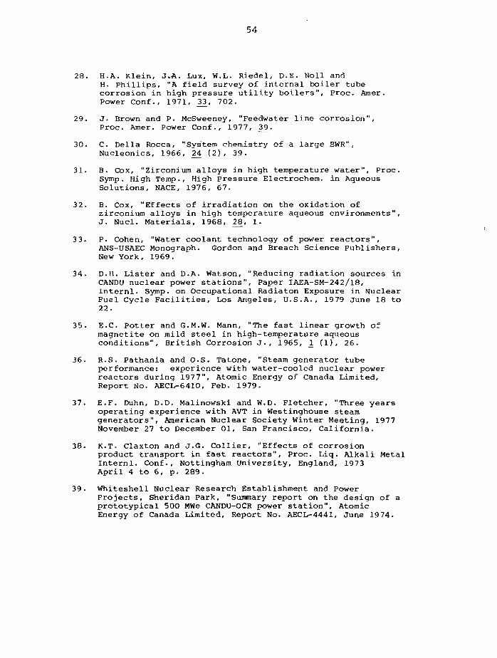
54
28. H.A. Klein, J.A. Lux, W.L. Riedel, D.E. Noll andH. Phillips, "A field survey of internal boiler tubecorrosion in high pressure utility boilers", Proc. Amer .Power Conf., 1971, X3, 702.
29. J. Brown and P. McSweeney, "Feedwater line corrosion",Proc. Amer. Power Conf., 1977, 39.
30. C. Delia Rocca, "System chemistry of a large BWR",Nucleonics, 1966, 24 (2), 39.
31. B. Cox, "Zirconium alloys in high temperature water", Proc.Symp. High Temp., High Pressure Electrochem. in AqueousSolutions, NACE, 1976, 67.
32. B. Cox, "Effects of irradiation on the oxidation ofzirconium alloys in high temperature aqueous environments",J. Nucl. Materials, 1968, 28, 1.
33. P. Cohen, "Water coolant technology of power reactors",ANS-USAEC Monograph. Gordon and Breach Science Publishers,New York, 1969.
34. D.H. Lister and D.A. Watson, "Reducing radiation sources inCANDU nuclear power stations", Paper IAEA-SM-242/18,Internl. Symp. on Occupational Radiaton Exposure in NuclearFuel Cycle Facilities, Los Angeles, U.S.A., 1979 June 18 to22.
35. E.C. Potter and G.M.W. Mann, "The fast linear growth ofmagnetite on mild steel in high-temperature aqueousconditions", British Corrosion J., 1965, 1̂ (1), 26.
36. R.S. Pathania and O.S. Tatone, "Steam generator tubeperformance: experience with water-cooled nuclear powerreactors during 1977", Atomic Energy of Canada Limited,Report No. AECL-6410, Feb. 1979.
37. E.F. Duhn, D.D. Malinowski and W.D. Fletcher, "Three yearsoperating experience with AVT in Westinghouse steamgenerators", American Nuclear Society Winter Meeting, 1977November 27 to December 01, San Francisco, California.
38. K.T. Claxton and J.G. Collier, "Effects of corrosionproduct transport in fast reactors", Proc. Liq. Alkali MetalInternl. Conf., Nottingham University, England, 1973April 4 to 6, p. 289.
39. Whiteshell Nuclear Research Establishment and PowerProjects, Sheridan Park, "Summary report on the design of aprototypical 500 MWe CANDU-OCR power station", AtomicEnergy of Canada Limited, Report No. AECL-4441, June 1974.
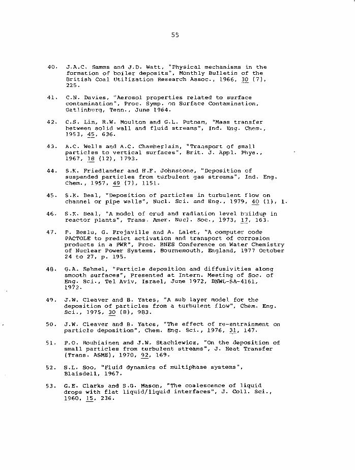
55
40. J.A.C. Samms and J.D. Watt, "Physical mechanisms in theformation of boiler deposits", Monthly Bulletin of theBritish Coal Utilization Research Assoc., 1966, 3£ (7),225.
41. C.N. Davies, "Aerosol properties related to surfacecontamination", Proc. Symp. on Surface Contamination,Gatlinburg, Tenn., June 1964.
42. C.S. Lin, R.W. Moulton and G.L. Putnam, "Mass transferbetween solid wall and fluid streams", Ind. Eng. Chem.,1953, 4J5, 636.
43. A.C. Wells and A.C. Chamberlain, "Transport of smallparticles to vertical surfaces", Brit. J. Appl. Phys•,1967, 18 (12), 1793.
44. S.K. Friedlander and H.F. Johnstone, "Deposition ofsuspended particles from turbulent gas streams", Ind. Eng.Chem., 1957, 49 (7), 1151.
45. S.K. Beal, "Deposition of particles in turbulent flow onchannel or pipe walls", Nucl. Sci. and Eng., 1979, 40 (1), 1.
46. S.K. Beal, "A model of crud and radiation level buildup inreactor plants", Trans. Amer. Nucl. Soc, 1973, 17, 163.
47. P. Beslu, G. Frejaville and A. Lalet, "A computer codePACTOLE to predict activation and transport of corrosionproducts in a PWR", Proc. BNES Conference on Water Chemistryof Nuclear Power Systems, Bournemouth, England, 1977 October24 to 27, p. 195.
48. G.A. Sehmel, "Particle deposition and diffusivities alongsmooth surfaces", Presented at Intern. Meeting of Soc. ofEng. Sci., Tel Aviv, Israel, June 1972, BNWL-SA-4161,1972.
49. J.W. Cleaver and B. Yates, "A sub layer model for thedeposition of particles from a turbulent flow", Chem. Eng.Sci., 1975, 30 (8), 983.
50. J.W. Cleaver and B. Yates, "The effect of re-entrainment onparticle deposition", Chem. Eng. Sci., 1976, 3^, 147.
51. P.O. Rouhiainen and J.W. Stachiewicz, "On the deposition ofsmall particles from turbulent streams", J. Heat Transfer(Trans. ASME) , 1970, 9J2, 169.
52. S.L. Soo, "Fluid dynamics of multiphase systems",Blalsdell, 1967.
53. G.E. Clarks and S.G. Mason, "The coalescence of liquiddrops with flat liquid/liquid interfaces", J. Coll. Sci.,1960, 15, 236.
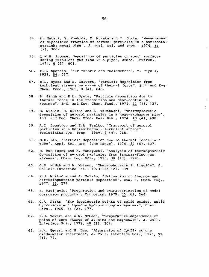
56
54. H. Matsui, Y. Yoshida, M. Murata and T. Ohata, "Measurementof deposition fraction of aerosol particles in a horizontalstraight metal pipe", J. Nucl. Sci. and Tech., 1974, ri(7), 300.
55. L.W.B. Browne, Deposition of particles on rough surfacesduring turbulent gas flow in a pipe", Atmos. Environ.,1974, 8 (8), 801.
56. P.S. Epstein, "Zur theorie des radiometers", Z. Physik,1929, 54, 537.
57. R.L. Byers and S. Calvert, "Particle deposition fromturbulent streams by means of thermal force", Ind. and Eng.Chem. Fund., 1969, 8 (4), 646.
58. B. Singh and R.L. Byers, "Particle deposition due tothermal force in the transition and near-continuumregimes", Ind. and Eng. Chem. Fund., 1972, 11̂ (1), 127.
59. G. Nishio, S. Kitani and K. Takahashi, "Thermophoreticdeposition of aerosol particles in a heat-exchanger pipe",Ind. and Eng. Chem. Proc. Des. Dev. , 1974, 1J3 (4), 408.
60. A.I. Leont'ev and E.A. Tsalko, "Transport of aerosolparticles in a nonisothermal, turbulent stream",Teplofizika Vys. Temp., 1969, 7 (4), 715.
61. S.H. Lin, "Particle deposition due to thermal force in atube", Appl. Sci. Res. (the Hague), 1976, 3̂2 (6), 637.
62. M. Moo-Young and K. Yamaguchi, "Analysis of thermophoreticdeposition of aerosol particles from laminar-flow gasstreams", Chem. Eng. Sci., 1975, ̂ ° (10), 1291.
63. G.S. McNab and A. Meisen, "Thermophoresis in liquids", J.Colloid Interface Sci., 1973, 44 (2), 339.
64. P.J. Whitmore and A. Meisen, "Estimation of thermo- anddiffusiophoretic particle deposition". Can. J. Chem. Eng.,1977, 5_5̂, 279.
65. E. Matijevic, "Preparation and characterization of modelcorrosion products". Corrosion, 1979, 3_5_ (6), 264.
66. G.A. Parks, "The isoelectric points of solid oxides, solidhydroxides and aqueous hydroxo complex systems", Chem.Revs., 1965, £5 (2), 177.
67. P.H. Tewari and A.W. McLean, "Temperature dependence ofpoint of zero charge of alumina and magnetite", J. Coll.Interface Sci., 1972, 40 (2), 267.
68. P.H. Tewari and W. Lee, "Adsorption of Co(II) at t.ieoxide-water interface", J. Coll. Interface Sci., 1975, 52(1), 77.
57
69. O.I. Martynova, A.A. Gromoglasov, A.Yu. Mikhailov andM.F. Nasyrov, "An investigation of the effect of temperatureon the electrophoretic mobility of particles of corrosionproducts", Teploenergetika, 1977, Z4 (2), 70.
70. T.R. Beck, D.W. Mahaffey and J.H. Olsen, "Wear of smallorifices by streaming current driven corrosion", J. BasicEng., Trans. ASME, 1970, 9J?, (D-4), 782.
71. P. Cohen, "The chemistry of water and solutions at hightemperatures for application to corrosion in powersystems", Symp. on Water Chem. and Aqueous Corrosion inSteam Generators (Conventional and Nuclear), Ermenonville,France, 1972, March 13 to 17.
72. V.P. Brusakov, "Laws for the deposition of materials onheat-transmitting surfaces under the action ofthermoelectric effects". Atom. Energiya, 1971, 3JD (1), 10.
73. S.K. Beal, "Correlations for the sticking probability anderosion of particles", J. Aerosol Sci., 1978, 9. ($)> 455.
74. A.P. Watkinson and N. Epstein, "Particulate fouling ofsensible heat exchangers". Heat Transfer 1970, Proc. 4thIntern. Heat Trans. Conf., Vol. 1, Paper HE 1.6,Versailles, 1971.
75. N. Epstein, "Fouling in heat exchangers", Proc. 6th Intern.Heat Transfer Conf., Vol. 6, p. 235, Toronto, 1978.
76. M. Corn, "The adhesion of solid particles to solidsurfaces. I. A review", J. Air Pollution Control Assocn.,1961, .U (11) , 523.
77. M. Corn, "The adhesion of solid particles to solidsurfaces, II", J. Air Pollution Control Assocn., 1961, ̂ 1(12), 566.
78. H. Krupp. "Particle adhesion, theory and experiment",Advances in Colloid and Interface Sci., 1967, 1̂ (2), 111.
79. E. Ruckenstein and D.C. Prieve, "Rate of deposition ofBrownian particles under the action of London and doublelayer forces", J. Chem. Soc. Faraday II, 1973, 69, 1522.
80. D.C. Prieve and E. Ruckenstein, "Effect of London forcesupon the rate of deposition of Brownian particles", A.I.Ch. E.J., 1974, 20 (6), 1178.
81. T.J. Kabele and J.W. Bartlett, "Deposition of ironcorrosion products from an aqueous stream", Chem. Eng.Progr. Symp. Series, 1970, 66 (104), 12.
82. T.J. Kabele, "Deposition of corrosion products from anaqueous stream", Ph.D. Thesis, Univ. of Rochester, 1969.
58
83. F.A. Means, "The formation and break-up of corrosionproduct agglomerates in the primary coolant of waterreactors", RD/B/N 4268, April 1978.
84. F.H. Sweeton and C.F. Baes, Jr., "The solubility ofmagnetite and hydrolysis of ferrous ion in aqueoussolutions at elevated temperatures", J. Chem. Thermod,1970, 2, 479.
85. M.H. Styrikovich, O.I. Martynova, I.F. Kobyakov,V.L. Men'shikova and M.I. Reznikov, "Solubility of magnetitein boiling water at high temperature", Teploenergetika,1971, :L8 (7) , 82.
86. M.A. Styrikovich, O.I. Martynova, I.F. Kobyakov,V.L. Men'shikova and M.I, Reznikov, "Solubility of magnetitein water at high temperature in a reducing medium",Teploenergetika, 1972, lj} (9), 85.
87. P.V. Balakrishnan, "A radiochemical technique for the studyof dissolution of corrosion products in high-temperaturewater". Can. J. Chem. Eng. , 1977, 5_5, 357.
88. Y.L. Sandier and R.H. Kunig, "The solubility ofnonstoichiometric nickel ferrite in high-temperature aqueoussolution", Nucl. Sci. and Eng., 1977, 64, 866.
89. R.G. Deissler, "Analysis of turbulent heat transfer, masstransfer and friction in smooth tubes at high Prandtl andSchmidt Numbers", Recent Advances in Heat and MassTransfer, J.P. Hartnett, Ed-, McGraw-Hill Book Company,Inc., New York, 1961.
90. D.H. Lister, "Mass transfer in the contamination ofisothermal steel surfaces", Nucl. Sci. and Eng., 1976, 61,107.
91. D.H. Lister and R.S. Pathania, "Radioactive contaminationunder applied potentials in high-temperature water".Corrosion, 1978, J34 (7), 236.
92. D.H. Lister, "The transport of radioactive corrosionproducts in high-temperature water - 1. Recalculating loopexperiments", Nucl. Sci. and Eng., 1975, 5_8, 239.
93. W.M. Campbell, A.W. Boyd, D.H. Charlesworth,R.F.S. Robertson and I. Sawatzky, "Development oforganic-liquid coolants", 3rd Intern. Conf., Peaceful UsesAtomic Energy, Geneva, 1964, Atomic Energy of Canada Limited,Report No. AECL-2015, 1964.
94. K.T. Claxton and J.G. Collier, "Mass transport of stainlesssteel corrosion products in flowing liquid sodium", J.Brit. Nucl. Energy Soc., 1973, 12 (1), 63.
59
95. R.A. Davies and J.L. Drummond, "The behaviour ofradioactive impurities in DFR primary liquid metalcoolant", TRG Report 2363 (D), Sept. 1973.
96. S.L. Goodstine and J.J. Kurpen, "Corrosion and corrosionproduct control in the utility boiler turbine cycle".Mater. Perf., 1974, r3 (1), 31.
97. A.L. Shvarts, Z.V. Deeva. A.S. Grigor'ev and L.E. Saichuk,"Deposit formation on internal heating surfaces ofgas/oil-fired supercritical boilers", Teploenergetika,1972, ]J> (7), 78.
98. M. Jakob, "Heat Transfer, Vol. 1", Wiley, 1949.
99. P. Cohen and L.E. Efferding, "Post-critical heat fluxfouling by system corrosion products in a model sodiumheated steam generator", Paper 76-WA/NE-12, ASME AnnualWinter Meeting, New York, Dec. 1976.
100. P. Cohen, "Chemical thermohydraulics of steam generatingsurfaces", 17th National Heat Trans. Conf., A.I.Ch.E.,1977.
101. R.V. MacBeth, R. Trenberth and R.W. Wood, "An investigationinto the effect of 'crud' deposits on surface temperature,dry-out and pressure drop, with forced convection boilingof water at 69 bar in an annular test section", AEEW-R705,May 1971.
102. T. Kelen and J. Arvesen, "Temperature increments fromdeposits on heat transfer surfaces: The thermalresistivity and thermal conductivity of deposits ofmagnetite, calcium hydroxy-apatite, humus and copperoxides", AE-459, 1972.
103. R.V. MacBeth, "Boiling on surfaces overlaid with a porousdeposit. Heat transfer rates obtained by capillaryaction", AEEW-R711, 1971.
104. N.G. Rassokhin, L.P. Kabanov, S.A. Tevlin and V.A. Tersin,"Thermal conductivity of iron oxide deposits",Teploenergetika, 1973, 9, 12.
105. V.P. Glebov, N.B. Eskin and V.M. Zusman, "The effect ofinternal iron oxide deposits on the operational temperatureconditions of the tubes of the radiant heating surfaces ofsupercritical boilers", Teploenergetika, 1975, 2^ (11),51.
106. A. Garlick, R. Sumerling and G.L. Shires, "Crud-inducedoverheating defects in water reactor fuel pins", J. Br.Nucl. Energy Soc. , 1977, _16 (1), 77.
107. N.N. Man'kina, "Conditions for forming ferric oxide scaledeposits", Teploenergetika, 1960, ]_ (3), 8.
60
108. N.N. Man'kina and B.L. Kokotov, "On the problem of themechanism of formation of iron oxide deposits",Teploenergetika, 1973, (9), 15.
109. L. Ahrnbom, "Aspects of crystalline deposit formation onsteam generating surfaces", V.G.B. Kraftwerkstechnik, 1975,5J5 (4) , 239.
110. D.H. Charlesworth, "The deposition of corrosion products inboiling water systems", Chem. Eng. Progr. Symp. Ser., 1970,66 (104), 21.
111. J.W. Palen and J.W. Westwater, "Heat transfer and foulingrates during pool boiling of calcium sulfate solutions",Chem. Eng. Progr. Symp. Ser., 1966, 6_2 (64), 77.
112. L. Kabanov, "Heat and mass transfer as related to corrosionproduct deposition", Energia Nucleare, 1971, 1J3 (5), 285.
113. A.A. Kot, "Water and water treatment in nuclear powerplants", Atomizdat, Moscow, 1964, (AEC-tr-6629, 1966).
114. L.F. Picone and W.D. Fletcher, "Post-irradiationexamination of Saxton fuel cladding corrosion products",WCAP-3269-57, 1966.
115. D. Thomas and U. Grigull, "Experimental investigation ofdeposition of suspended magnetite from the fluid flow insteam generating boiler tubes", Bremst.-Warme-Kraft, 1974,2£ (3), 109.
116. Y. Asakura, M. Kikuchi, S. Uchida and Y. Yusa, "Iron oxidedeposition on heated surfaces in boiling water", Nucl. Sci.and Eng., 1978, 6_7 (1), 1.
117. N.B. Hospeti and R.B. Mesler, "Deposits formed beneathbubbles during nucleate boiling of radioactive calciumsurfate solutions", A.I.Ch.E.J., 1965, 11̂ (4), 662.
118. D.E. Woodmansee, "Bench scale experiments on the mechanismof iron oxide deposition". Presented at A.I.Ch.E. 65thAnnual Meeting, New York, 1972.
119. T. Iwahori, T. Mizuno and H. Koyama, "Crud deposition onheat transfer surface". Paper 37, Corrosion/78, AnnualConference of the Corrosion Society (NACE), Houston, Texas,6-10 March 1978.
120. C. Wohlberg and F.W. Kleimola, "Factors which affectformation and deposition of transport corrosion products inhigh-temperature recirculating water loops", ANL-5195(Rev.), 1953.
121. A.L. Medin (Editor), "Literature Survey for ActivityBuild-up on Reactor Primary System Components", APAE-25,USAEC Contract No. AT(ll-l)-318, January 1958.
61
122. G.R. Vavasour (Editor), "Proc. Tripartite Conf. onTransport of Materials in PWR Systems, Chalk River,February-March 1961", Atomic Energy of Canada Limited,Report No. AECL-1265.
123. J.W. Bartlett, "Radioactivity Buildup in ReactorComponents", Power Engineering, p. 36, February 1969.
124. S.G. Sawochka, N.P. Jacob and W.L. Pearl, "Primary systemshutdown radiation levels at nuclear power generatingstations", Proc. of System Contamination Workshop(Sponsored by Electric Power Research Institute), Atlanta,Georgia, 1976 March 15 to 17.
125. W.E. Berry and R.B. Diegle, "Survey of corrosion producttransport in light water nuclear reactors", Paper 157,Corrosion/78, Annual Conference of the Corrosion Society(NACE), Houston, Texas, 1978 March 6 to 10.
126. D.H. Lister, "The mechanisms of corrosion product transportand their investigation in high temperature water loops".Corrosion, 1978, _3_5 (3), 89.
127. N.K. Taylor, "Mass transfer of corrosion products in PWR,BWR and SGHWR systems", Rev. Coat. Corrosion, 1978, 2_ (4),261.
128. A.B. Johnson, Jr. and W.F. Vogelsang, "Preliminaryassessment of corrosion product transport in fusionreactors", Nucl. Technol., 1974, ̂ (1), 115.
129. K.A. Burrill, "An experimental study to link waterchemistry with corrosion product deposits in-reactor",Proc. BNES Conference on Water Chemistry of Nuclear ReactorSystems, Bournemouth, England, 1977 October 24 to 27, p.119.
130. K.A. Burrill, "Corrosion product depositon and release atnuclear fuel sheaths in boiling water". Corrosion, 1979, 35(2), 84.
131. K.A. Burrill and A. Shaddick, "Water chemistry and thedeposition of corrosion products on nuclear reactor fuel:A summary of experimental results", Atomic Energy of CanadaLimited, Report No. AECL-6952, in preparation.
132. K.A. Burrill, "Corrosion product transport in water-coolednuclear reactors. Part II: boiling water with directcycle operation". Can. J. Chem. Eng. , 1978, 5_6, 79.
13 3. C.R. Bergen, "Activity buildup control by high pH coolant -a literature survey", APAE Memo No. 280, AEC R and D ReportUC-81, Jan. 1961.
134. R.F.S. Robertson, "Chalk River Experience in 'crud'deposition problems". Atomic Energy of Canada Limited,Report No. AECL-1328, 1961.
62
135. K.A. Burrill, "Corrosion product transport in water-coolednuclear reactors. Part I - Pressurized water operation",Can. J. Chem. Eng. , 1977, 5J5, 54.
136. K.A. Burrill, "A possible mechanism for corrosion producttransport and radiation field growth in a pressurized waterreactor primary circuit", Nucl. T^chnol., 1977, 36, 85.
137. Y. Solomon and J. Roesmer, "Some observations on thepossible relationship of reactor coolant chemistry andradiation level buildup", WCAP-9407, Nov. 1978.
138. D.H. Lister, "The behaviour of dissolved cobalt in the coresof water-cooled nuclear reactors", for presentation atBNES Conf. on Water Chemistry of Nuclear Reactor Systems,Bournemouth, England, 1980 October 13 to 17.
139. F.F. Bogdanov, "Some causes of deposits on heating surfaceswhich are cooled by organic coolants", Teploenergetika,1970, r7 (1), 64.
140. R. Nijsing, "Diffusional and kinetic phenomena associatedwith fouling", EUR-543e, 1964.
141. D.H. Lister, "The transport of radioactive corrosionproducts in high temperature water. II - The activation ofisothermal steel surfaces", Nucl. Sci. and Eng., 1976, 59,406.
142. D.H. Lister, "The accumulation of radioactive corrosionproducts in nuclear steam generators". Corrosion, 1979, 3J5(5), 219.
143. D.H. Lister, "The growth of radiation fields around CANDUBoilers", Proc. BNES Conf. on Water Chemistry of NuclearReactor Systems", Bournemouth, England, 1977 October 24 to27, p.207.
144. D.H. Lister, "Predicting radiation fields around reactorcomponents", Atomic Energy of Canada Limited, Report No.AECL-5522, 1976.
145. W.R. DeHollander, "A model for cobalt 60/58 deposition onprimary coolant piping in a boiling water reactor".Corrosion, 1979, 35 (4), 147.
146. S. Yerazunis, E.H. Alkire and R.L. Seidel, "Mechanisms ofReactor System Activation", KAPL-M-SIMS-98, Knolls AtomicPower Laboratory, 1959.
147. J. Pattison and G.N. Walton, "The distribution ofradioactive materials in a circuit", AERE-R-3661, 1961.
148. G.N. Walton and E. Hesford, "The migration of activatedcorrosion products in high-pressure water loops". Corrosionof Reactor Materials, p. 547, International Atomic EnergyAgency, Vienna, Austria, 1962.
63
149. A.P. Veselkin and O. Ya. Shakh, "The effect of adecontamination system on the buildup of active corrosionproducts in pressurized water reactors", Soviet At. Energy,1966, 20 (3), 273.
150. D.H. Lister, "Reduction of radioactivity transport in CANDUpower plants", Energia Nucleare, 1979, 2<6 (10), 472.
151. L.F. Epstein and T.F. Evans, "Deposition of matter from aflowing stream", GEAP-4140, General Electric Co., 1962.
152. R. Bonalumi and A. Olivi, "General method for studyingcorrosion product buildup in primary circuit of a reactor,Energia Nucleare, 1970, JL7 (5), 302.
153. C.F. Clement, "Theory of mass transport in liquidcircuits", AERE-TP 606, 1975.
154. S.A. Kushneriuk and J.M. Blair, "Dispersion of radioactivematerials by a fluid flowing in a pipe", Nucl. Sci. andEng., 1976, 60, 87.
155. K. Lauridsen, "Development of a model for the assessment ofradiation fields around nuclear power plant components",Ris<» Report No. 353, 1977.
156. J.C. Cunnane, D.L. Uhl and A.J. Kennedy, "Dynamic corrosionproduct transport in pressurized water reactors". Paper155, Corrosion/78, Annual Conference of the CorrosionSociety (NACE), Houston, Texas, 1978 March 06 to 10.
157. J.W. Bartlett, "Theory of corrosion product generation,dispersion and activation processes", BNWL-676, BattellePacific Northwest Laboratories, 1968.
158. G. Frejaville, A. Marchal, P. Beslu and A. Lalet, "Activitedu circuit primaire de la centrale nucleaire des Ardennesdue aux produits de corrosion", IAEA-SM-178/31, 1974.
159. S. Uchida, M. Kikuchi, Y. Asakura, H. Yusa and K. Ohsumi,"A calculation model for predicting concentrations ofradioactive corrosion products in the primary coolant ofboiling water reactors", Nucl. Sci. and Eng., 1978, &1_ (2),247.
160. S. Uchida, M. Kitamura, M. Kikuchi, H. Yusa, K. Ohsumi andY. Matsushima, "An empirical formula predicting shutdowndose rate of the recirculating pipes in boiling waterrectors", Nucl. Sci. and Eng., 1979, 69 (1), 78.
161. R. Gasparini, C. Delia Rocca and E. Ioannilli, "A newapproach to the study and prevention of deposits in modernpower stations", Combustion, Nov. 1369, p. 12.
64
162. K.A. Burrill, "The deposition of magnetite particles fromhigh velocity water onto isothermal tubes". Atomic Energyof Canada Limited, Report No. AECL-5308, Feb. 1977.
163. F.D. Nicholson and J.V. Evans, "Efftct of nickel hydroxideinjections on the mass transfer of corrosion products inhigTi temperature, >iigh pressure water circuits", Corrosion,1979, 5̂_ (4), 158.
164. W.F. Brehm, P.L. Koehmstedt, E.A. Kovacevich andD.W. Shannon, "Radioactivity in FFTF closed loops",BNWL-585, Oct. 1967.
165. D.H. Lester, "Comments on mass transport and scale-upproblems in circulating sodium systems", BNWL-cc-2131, May1969.
166. L.P. Epstein, "Static and dynamic corrosion and masstransport in liquid metal systems", Chem. Eng. Progr. Symp.Series, 1957, ̂ 3 (20), 67.
167. K.T. Claxton and J.G. Collier, "Effects of corrosionproduct transport in fast reactors", Proc. Liq. AlkaliMetal Internl. Conf., Nottingham University, England, 1973April 4 to 6, p- 289.
168. W.E. Ray, R.L. Miller, S.L. Schrock and G.A. Whitlow,"Structure of sodium corrosion deposits and their effect onheat transfer coefficients", Nucl. Technol., 1972, lj> (1),249.
169. A.J. Hooper, "Application of physical examinationtechniques in the study of corrosion and deposition inliquid metals", Proc. Liq. Alkali Metal Internl- Conf.,Nottingham University, England, 1973 April 4 to 6, p. 201.
170. A. Merkel and G. Menken, "Estimation of the radiationlevels near the components of the SNR-300 primary systeminduced by deposition of active corrosion products", Proc.Liq. Alkali Metal Internl. Conf., Nottingham University,England, 1973 April 4 to 6, p. 301.
171. M.V. Polley, "Analysis of the selective mass transfer ofalloys exposed to flowing sodium", RD/B/N 3024, Feb. 1976.
172. P. Beslu, L. Costa, G. Frejaville and P. Pepin, "Predictionof primary circuit contamination in power reactors",Atomkernenergie, 1977, K> ^4'' 297.
173. R.B. Ritter and J.W. Suitor, "Sea water fouling of heatexchanger tubes", A.I.Ch.E. Second National Conf. onComplete Water Reuse, 1975.
174. H.T. Michels, W.W. Kirk and A.H. Tuthill, "The role ofcorrosion and fouling in steam condenser performance",Nuclear Energy, 1978, r7 (4), 335.
65
175. C. Pearson, "Role of iron in the inhibition of corrosion ofmarine heat exchangers. A review", British Corrosion J.,1972, 7, 61.
176. R.F. North and M.J. Pryor, "The protection of Cu by ferroussulphate additions", Corros. Sci., 1968, 8, 149.
177. J.E. Castle, D.C. Epler and D.B. Peplow, "ESCAinvestigation of iron-rich protective films on aluminiumbrass condenser tubes", Corros. Sci., 1976, 16 (3), 145.
178. R. Gasparini, C. Delia Rocca and E. Ioannilli, "Mechanismof protective film format:on on Cu-alloy condenser tubeswith FeSO4 treatment", Corros. Sci., 1970, 1C), 157.
179. K.D. Efird, "The inter-relation of corrosion and foulingfor metals in sea water". Materials Perf., 1976, 1J5 (4),16.
ISSN 0067 - 0367
To identify individual documents in the series
we have assigned an AECL- number to each.
Please refer to the AECL- number when re-
questing additional copies of this document
from
Scientific Document Distribution Office
Atomic Energy of Canada Limited
Chalk River, Ontario, Canada
KOJ 1J0
ISSN 0067 - 0367
Pour identifier les rapports individuels faisant
partie de cette serie nous avons assigne
un numero AECL- a chacun.
Veuillez faire mention du numero AECL- si
vous demandez d'autres exemplaires de ce
rapport
Service de Distribution des Documents Officiels
L'Energie Atomique du Canada Li mi tee
Chalk River, Ontario, Canada
KOJ 1J0
Price $5.00 per copy Prix $5.00 par exemplaire
1531-80