Embed Size (px)
Citation preview

7278_half 2/8/06 3:23 PM Page 1
© 2006 by Taylor & Francis Group, LLC

CORROSION TECHNOLOGY
EditorPhilip A. Schweitzer, P.E.
ConsultantYork, Pennsylvania
Corrosion Protection Handbook: Second Edition, Revised and Expanded,edited by Philip A. Schweitzer
Corrosion Resistant Coatings Technology, Ichiro SuzukiCorrosion Resistance of Elastomers, Philip A. SchweitzerCorrosion Resistance Tables: Metals, Nonmetals, Coatings, Mortars, Plastics,
Elastomers and Linings, and Fabrics: Third Edition, Revised and Expanded(Parts A and B), Philip A. Schweitzer
Corrosion-Resistant Piping Systems, Philip A. SchweitzerCorrosion Resistance of Zinc and Zinc Alloys: Fundamentals and Applications,
Frank PorterCorrosion of Ceramics, Ronald A. McCauleyCorrosion Mechanisms in Theory and Practice, edited by P. Marcus and J. OudarCorrosion Resistance of Stainless Steels, C. P. DillonCorrosion Resistance Tables: Metals, Nonmetals, Coatings, Mortars, Plastics,
Elastomers and Linings, and Fabrics: Fourth Edition, Revised and Expanded (Parts A, B, and C), Philip A. Schweitzer
Corrosion Engineering Handbook, edited by Philip A. SchweitzerAtmospheric Degradation and Corrosion Control, Philip A. SchweitzerMechanical and Corrosion-Resistant Properties of Plastics and Elastomers,
Philip A. SchweitzerEnvironmental Degradation of Metals, U. K. Chatterjee, S. K. Bose,
and S. K. RoyEnvironmental Effects on Engineered Materials, edited by Russell H. JonesCorrosion-Resistant Linings and Coatings, Philip A. SchweitzerCorrosion Mechanisms in Theory and Practice: Second Edition, Revised
and Expanded, edited by Philippe MarcusElectrochemical Techniques in Corrosion Science and Engineering, Robert G. Kelly,
John R. Scully, David W. Shoesmith, and Rudolph G. BuchheitMetallic Materials: Physical, Mechanical, and Corrosion Properties,
Philip A. SchweitzerCorrosion Resistance Tables: Metals, Nonmetals, Coatings, Mortars, Plastics,
Elastomers and Linings, and Fabrics: Fifth Edition, Philip A. Schweitzer
7278_series 2/8/06 3:24 PM Page 1
© 2006 by Taylor & Francis Group, LLC

Corrosion of Ceramic and Composite Materials, Second Edition,Ronald A. McCauley
Analytical Methods in Corrosion Science and Engineering, Philippe Marcus and Florian Mansfeld
Paint and Coatings: Applications and Corrosion Resistance, Philip A. SchweitzerCorrosion Control Through Organic Coatings, Amy Forsgren
7278_series 2/8/06 3:24 PM Page 2
© 2006 by Taylor & Francis Group, LLC

7278_title 2/8/06 3:22 PM Page 1
A CRC title, part of the Taylor & Francis imprint, a member of theTaylor & Francis Group, the academic division of T&F Informa plc.
Boca Raton London New York
© 2006 by Taylor & Francis Group, LLC

Published in 2006 byCRC PressTaylor & Francis Group 6000 Broken Sound Parkway NW, Suite 300Boca Raton, FL 33487-2742
© 2006 by Taylor & Francis Group, LLCCRC Press is an imprint of Taylor & Francis Group
No claim to original U.S. Government worksPrinted in the United States of America on acid-free paper10 9 8 7 6 5 4 3 2 1
International Standard Book Number-10: 0-8493-7278-X (Hardcover) International Standard Book Number-13: 978-0-8493-7278-0 (Hardcover) Library of Congress Card Number 2005055971
This book contains information obtained from authentic and highly regarded sources. Reprinted material isquoted with permission, and sources are indicated. A wide variety of references are listed. Reasonable effortshave been made to publish reliable data and information, but the author and the publisher cannot assumeresponsibility for the validity of all materials or for the consequences of their use.
No part of this book may be reprinted, reproduced, transmitted, or utilized in any form by any electronic,mechanical, or other means, now known or hereafter invented, including photocopying, microfilming, andrecording, or in any information storage or retrieval system, without written permission from the publishers.
For permission to photocopy or use material electronically from this work, please access www.copyright.com(http://www.copyright.com/) or contact the Copyright Clearance Center, Inc. (CCC) 222 Rosewood Drive,Danvers, MA 01923, 978-750-8400. CCC is a not-for-profit organization that provides licenses and registrationfor a variety of users. For organizations that have been granted a photocopy license by the CCC, a separatesystem of payment has been arranged.
Trademark Notice: Product or corporate names may be trademarks or registered trademarks, and are used onlyfor identification and explanation without intent to infringe.
Library of Congress Cataloging-in-Publication Data
Forsgren, Amy.Corrosion control through organic coatings / Amy Forsgren.
p. cm.Includes bibliographical references and index.ISBN 0-8493-7278-X (alk. paper)1. Protective coatings. 2. Corrosion and anti-corrosives. 3. Organic compounds. I. Title.
TA418.76.F67 2005620.1’1223--dc22 2005055971
Visit the Taylor & Francis Web site at http://www.taylorandfrancis.com
and the CRC Press Web site at http://www.crcpress.com
Taylor & Francis Group is the Academic Division of Informa plc.
7278_Discl.fm Page 1 Thursday, December 8, 2005 10:49 PM
© 2006 by Taylor & Francis Group, LLC

Dedication
To my son Erik and my husband Dr. Per-Ola Forsgren, without their support and encouragement this book would
not have been possible.
7278_C000.fm Page vii Tuesday, March 7, 2006 12:12 PM
© 2006 by Taylor & Francis Group, LLC

Preface
This book has been written to fill a gap in the literature of corrosion-protectioncoatings by offering a bridge between the very brief account of paints conveyed inmost corrosion books and the very comprehensive, specialized treatises found in thepolymer or electrochemical scientific publications.
I have tried to write this book for the following audiences:
• Maintenance engineers who specify or use anticorrosion paints and needa sound working knowledge of different coating types and some orienta-tion in how to test coatings for corrosion protection
• Buyers or specifiers of coatings, who need to know quickly which testsprovide useful knowledge about performance and which do not
• Researchers working with accelerated test methods, who need an in-depthknowledge of aging mechanisms of coatings, in order to develop moreaccurate tests
• Applicators interested in providing safe working environments for per-sonnel performing surface preparation
• Owners of older steel structures who find themselves faced with removalof lead-based paint (LBP) when carrying out maintenance painting
The subject matter is dictated by the problems all these groups face. LBPdominates parts of the book. Although this coating is on its way out, the problemsit has created remain. Replacement pigments of equivalent — even better — qualitycertainly exist but are not as well known to the general coatings public as we wouldwish. This is partly due to the chaotic conditions of accelerated testing. Hundredsof test methods exist, with no consensus in the industry about which ones are useful.This confusion has not aided the efforts toward identification and acceptance of thebest candidates to replace LBP. And finally, the issues associated with disposal oflead-contaminated blasting debris are expected to become more pressing, not lessso, in the future.
However, not all modern maintenance headaches are due to lead. Another prob-lem facing plant engineers and applicators of coatings is silicosis from abrasiveblasting with quartz sand. This blasting material is outlawed in many industrializedcountries, but sadly, not all. Even in Scandinavia, where worker health is taken veryseriously, the ban is not as complete as it should be. And, because we all need theozone layer, limiting the use of volatile organic compounds where possible is aconsideration for today’s engineers.
The reader will no doubt notice that, while the book provides plant engineerswith a rapid orientation in coating types, abrasives, laboratory techniques, anddisposal issues, certain other areas of interest to the same audience are not addressed
7278_C000.fm Page ix Tuesday, March 7, 2006 12:12 PM
© 2006 by Taylor & Francis Group, LLC

in this work. Areas such as surface preparation standards, applications methods, andquality control are important and interesting, but in writing a book, it is not possibleto include everything. One must draw the line somewhere, and I have chosen todraw it thusly: subjects are not taken up here if they are thoroughly covered in otherpublications, and the information has already reached a wide audience.
7278_C000.fm Page x Tuesday, March 7, 2006 12:12 PM
© 2006 by Taylor & Francis Group, LLC

Author
Amy Forsgren
received her chemical engineering education at the University ofCincinnati in Ohio in 1986. She then did research in coatings for the paper industryfor 3 years, before moving to Detroit, Michigan. There, she spent 6 years in anti-corrosion coatings research at Ford Motor Company, before returning to Sweden in1996 to lead the protective coatings program at the Swedish Corrosion Institute. In2001, she joined the telecom equipment industry in Stockholm. Mrs. Forsgren livesin Stockholm with her family.
7278_C000.fm Page xi Tuesday, March 7, 2006 12:12 PM
© 2006 by Taylor & Francis Group, LLC

Acknowledgments
Without the help of many people, this book would not have been possible. I wishin particular to thank my colleague Lars Krantz for generously creating the illustra-tions. Mats Linder and Bertil Sandberg of the Swedish Corrosion Institute alsoreceive my thanks for supporting the waterborne coatings and lead abatementresearch programs, as do my colleagues at Semcon AB for taking interest andproviding encouragement.
7278_C000.fm Page xiii Tuesday, March 7, 2006 12:12 PM
© 2006 by Taylor & Francis Group, LLC

Contents
Chapter 1
Introduction ..........................................................................................1
1.1 Scope of the Book ...........................................................................................11.1.1 Target Group Description ....................................................................11.1.2 Specialties Outside the Scope..............................................................2
1.2 Protection Mechanisms of Organic Coatings ..................................................21.2.1 Diffusion of Water and Oxygen...........................................................31.2.2 Electrolytic Resistance.........................................................................51.2.3 Adhesion...............................................................................................6
1.2.3.1 What Adhesion Accomplishes..............................................61.2.3.2 Wet Adhesion........................................................................71.2.3.3 Important Aspects of Adhesion ............................................7
1.2.4 Passivating with Pigments ...................................................................81.2.5 Alternative Anodes (Cathodic Protection)...........................................8
References..................................................................................................................8
Chapter 2
Composition of the Anticorrosion Coating .......................................11
2.1 Coating Composition Design.........................................................................112.2 Binder Types..................................................................................................11
2.2.1 Epoxies ...............................................................................................122.2.1.1 Chemistry............................................................................122.2.1.2 Ultraviolet Degradation ......................................................132.2.1.3 Variety of Epoxy Paints......................................................14
2.2.2 Acrylics ..............................................................................................152.2.2.1 Chemistry............................................................................152.2.2.2 Saponification .....................................................................172.2.2.3 Copolymers .........................................................................18
2.2.3 Polyurethanes .....................................................................................182.2.3.1 Moisture-Cure Urethanes....................................................202.2.3.2 Chemical-Cure Urethanes...................................................202.2.3.3 Blocked Polyisocyanates ....................................................212.2.3.4 Health Issues.......................................................................212.2.4.5 Waterborne Polyurethanes ..................................................22
2.2.4 Polyesters ...........................................................................................222.2.4.1 Chemistry............................................................................222.2.4.2 Saponification .....................................................................232.2.4.3 Fillers ..................................................................................23
2.2.5 Alkyds ................................................................................................232.2.5.1 Chemistry............................................................................242.2.5.2 Saponification .....................................................................24
7278_C000.fm Page xv Tuesday, March 7, 2006 12:12 PM
© 2006 by Taylor & Francis Group, LLC

2.2.5.3 Immersion Behavior ...........................................................242.2.5.4 Brittleness ...........................................................................242.2.5.5 Darkness Degradation.........................................................25
2.2.6 Chlorinated Rubber ............................................................................252.2.6.1 Chemistry............................................................................252.2.6.2 Dehydrochlorination ...........................................................25
2.2.7 Other Binders .....................................................................................262.2.7.1 Epoxy Esters .......................................................................262.2.7.2 Silicon-Based Inorganic Zinc-Rich Coatings.....................26
2.3 Corrosion-Protective Pigments ......................................................................272.3.1 Types of Pigments..............................................................................27
2.3.1.1 A Note on Pigment Safety .................................................272.3.2 Lead-Based Paint ...............................................................................27
2.3.2.1 Mechanism on Clean (New) Steel .....................................282.3.2.2 Mechanism on Rusted Steel ...............................................282.3.2.3 Summary of Mechanism Studies .......................................302.3.2.4 Lead-Based Paint and Cathodic Potential..........................30
2.3.3 Phosphates ..........................................................................................312.3.3.1 Zinc Phosphates ..................................................................312.3.3.2 Types of Zinc Phosphates...................................................332.3.3.3 Accelerated Testing and Why Zinc Phosphates
Commonly Fail ...................................................................352.3.3.4 Aluminum Triphosphate .....................................................362.3.3.5 Other Phosphates ................................................................36
2.3.4 Ferrites................................................................................................372.3.5 Zinc Dust............................................................................................392.3.6 Chromates...........................................................................................40
2.3.6.1 Protection Mechanism .......................................................402.3.6.2 Types of Chromate Pigments .............................................402.3.6.3 Solubility Concerns ............................................................41
2.3.7 Other Inhibitive Pigments ..................................................................412.3.7.1 Calcium-Exchanged Silica..................................................412.3.7.2 Barium Metaborate .............................................................422.3.7.3 Molybdates..........................................................................422.3.7.4 Silicates ...............................................................................43
2.3.8 Barrier Pigments ................................................................................442.3.8.1 Mechanism and General Information.................................442.3.8.2 Micaceous Iron Oxide ........................................................452.3.8.3 Other Nonmetallic Barrier Pigments..................................462.3.8.4 Metallic Barrier Pigments...................................................46
2.3.9 Choosing a Pigment ...........................................................................472.4 Additives.........................................................................................................48
2.4.1 Flow and Dispersion Controllers .......................................................482.4.1.1 Thixotropic Agents .............................................................492.4.1.2 Surfactants...........................................................................492.4.1.3 Dispersing Agents...............................................................49
7278_C000.fm Page xvi Tuesday, March 7, 2006 12:12 PM
© 2006 by Taylor & Francis Group, LLC

2.4.2 Reactive Reagents ..............................................................................502.4.3 Contra-Environmental Chemicals ......................................................502.4.4 Special Effect Inducers ......................................................................51
References................................................................................................................51
Chapter 3
Waterborne Coatings..........................................................................55
3.1 Technologies for Polymers in Water .............................................................563.1.1 Water-Reducible Coatings and Water-Soluble Polymers ..................563.1.2 Aqueous Emulsion Coatings..............................................................563.1.3 Aqueous Dispersion Coatings............................................................56
3.2 Water vs. Organic Solvents............................................................................573.3 Latex Film Formation ....................................................................................57
3.3.1 Driving Force of Film Formation ......................................................583.3.2 Humidity and Latex Cure ..................................................................593.3.3 Real Coatings .....................................................................................60
3.3.3.1 Pigments..............................................................................603.3.3.2 Additives .............................................................................62
3.4 Minimum Film Formation Temperature ........................................................623.4.1 Wet MFFT and Dry MFFT................................................................63
3.5 Flash Rusting..................................................................................................63References................................................................................................................64
Chapter 4
Blast Cleaning and Other Heavy Surface Pretreatments ..................67
4.1 Introduction to Blast Cleaning.......................................................................684.2 Dry Abrasive Blasting....................................................................................68
4.2.1 Metallic Abrasives..............................................................................694.2.2 Naturally Occurring Abrasives ..........................................................694.2.3 By-Product Abrasives.........................................................................70
4.2.3.1 Variations in Composition and Physical Properties...........714.2.4 Manufactured Abrasives.....................................................................71
4.3 Wet Abrasive Blasting and Hydrojetting .......................................................724.3.1 Terminology .......................................................................................734.3.2 Inhibitors ............................................................................................734.3.3 Advantages and Disadvantages of Wet Blasting ...............................744.3.4 Chloride Removal ..............................................................................754.3.5 Water Containment.............................................................................75
4.4 Unconventional Blasting Methods.................................................................764.4.1 Carbon Dioxide ..................................................................................764.4.2 Ice Particles ........................................................................................774.4.3 Soda....................................................................................................77
4.5 Testing for Contaminants after Blasting .......................................................784.5.1 Soluble Salts.......................................................................................784.5.2 Hydrocarbons .....................................................................................794.5.3 Dust ....................................................................................................80
7278_C000.fm Page xvii Tuesday, March 7, 2006 12:12 PM
© 2006 by Taylor & Francis Group, LLC

4.6 Dangerous Dust: Silicosis and Free Silica ....................................................814.6.1 What is Silicosis?...............................................................................814.6.2 What Forms of Silica Cause Silicosis? .............................................824.6.3 What is a Low-Free-Silica Abrasive?................................................824.6.4 What Hygienic Measures Can Be Taken
to Prevent Silicosis? ...........................................................................82References................................................................................................................83
Chapter 5
Abrasive Blasting and Heavy-Metal Contamination.........................85
5.1 Detecting Contamination ...............................................................................855.1.1 Chemical Analysis Techniques for Heavy Metals.............................865.1.2 Toxicity Characteristic Leaching Procedure......................................86
5.2 Minimizing the Volume of Hazardous Debris...............................................875.2.1 Physical Separation ............................................................................88
5.2.1.1 Sieving ................................................................................885.2.1.2 Electrostatic Separation ......................................................88
5.2.2 Low-Temperature Ashing (Oxidizable Abrasive Only).....................895.2.3 Acid Extraction and Digestion ..........................................................89
5.3 Methods for Stabilizing Lead ........................................................................905.3.1 Stabilization with Iron .......................................................................905.3.2 Stabilization of Lead through pH Adjustment ..................................915.3.3 Stabilization of Lead with Calcium Silicate and
Other Additives ..................................................................................925.3.3.1 Calcium Silicate..................................................................925.3.3.2 Sulfides................................................................................92
5.4 Debris as Filler in Concrete...........................................................................935.4.1 Problems that Contaminated Debris Pose
for Concrete........................................................................................935.4.2 Attempts to Stabilize Blasting Debris with Cement .........................945.4.3 Problems with Aluminum in Concrete ..............................................965.4.4 Trials with Portland Cement Stabilization ........................................96
5.5 Other Filler Uses............................................................................................97References................................................................................................................97
Chapter 6
Weathering and Aging of Paint..........................................................99
6.1 UV Breakdown.............................................................................................1006.1.1 Reflectance .......................................................................................1016.1.2 Transmittance ...................................................................................1016.1.3 Absorption........................................................................................101
6.2 Moisture .......................................................................................................1036.2.1 Chemical Breakdown .......................................................................1046.2.2 Weathering Interactions ...................................................................1046.2.3 Hygroscopic Stress...........................................................................1046.2.4 Blistering/Adhesion Loss.................................................................105
7278_C000.fm Page xviii Tuesday, March 7, 2006 12:12 PM
© 2006 by Taylor & Francis Group, LLC

6.2.4.1 Alkaline Blistering............................................................1066.2.4.2 Neutral Blistering..............................................................106
6.3 Temperature..................................................................................................1076.4 Chemical Degradation..................................................................................108References..............................................................................................................111
Chapter 7
Corrosion Testing — Background and Theoretical Considerations ..................................................................................113
7.1 The Goal of Accelerated Testing .................................................................1137.2 What Factors Should Be Accelerated? ........................................................114
7.2.1 UV Exposure....................................................................................1157.2.2 Moisture ...........................................................................................1157.2.3 Drying...............................................................................................117
7.2.3.1 Faster Corrosion during the Wet–Dry Transition.............1177.2.3.2 Zinc Corrosion — Atmospheric Exposure vs. Wet
Conditions .........................................................................1187.2.3.3 Differences in Absorption and Desorption Rates ............120
7.2.4 Temperature......................................................................................1207.2.5 Chemical Stress................................................................................1217.2.6 Abrasion and Other Mechanical Stresses........................................1237.2.7 Implications for Accelerated Testing ...............................................123
7.3 Why There is No Single Perfect Test..........................................................1237.3.1 Different Sites Induce Different Aging Mechanisms......................1247.3.2 Different Coatings Have Different Weaknesses ..............................1257.3.3 Stressing the Achilles’ Heel .............................................................126
References..............................................................................................................126
Chapter 8
Corrosion Testing — Practice..........................................................129
8.1 Some Recommended Accelerated Aging Methods .....................................1298.1.1 General Corrosion Tests...................................................................130
8.1.1.1 ASTM D5894 ...................................................................1308.1.1.2 NORSOK ..........................................................................130
8.1.2 Condensation or Humidity...............................................................1318.1.3 Weathering........................................................................................1318.1.4 Corrosion Tests from the Automotive Industry...............................131
8.1.4.1 VDA 621-415 ...................................................................1328.1.4.2 Volvo Indoor Corrosion Test or Volvo-cycle ...................1328.1.4.3 SAE J2334 ........................................................................133
8.1.5 A Test to Avoid: Kesternich.............................................................1338.2 Evaluation after Accelerated Aging .............................................................134
8.2.1 General Corrosion ............................................................................1358.2.1.1 Creep from Scribe ............................................................1358.2.1.2 Other General Corrosion ..................................................135
7278_C000.fm Page xix Tuesday, March 7, 2006 12:12 PM
© 2006 by Taylor & Francis Group, LLC

8.2.2 Adhesion...........................................................................................1368.2.2.1 The Difficulty of Measuring Adhesion ............................1368.2.2.2 Direct Pull-off Methods....................................................1378.2.2.3 Lateral Stress Methods .....................................................1388.2.2.4 Important Aspects of Adhesion ........................................140
8.2.3 Barrier Properties .............................................................................1408.2.4 Scanning Kelvin Probe ....................................................................1428.2.5 Scanning Vibrating Electrode Technique.........................................1438.2.6 Advanced Analytical Techniques.....................................................144
8.2.6.1 Scanning Electron Microscopy.........................................1448.2.6.2 Atomic Force Microscopy................................................1448.2.6.3 Infrared Spectroscopy.......................................................1448.2.6.4 Electron Spectroscopy ......................................................1468.2.6.5 Electrochemical Noise Measurement ...............................147
8.3 Calculating Amount of Acceleration and Correlations ...............................1478.3.1 Acceleration Rates ...........................................................................1488.3.2 Correlation Coefficients or Linear Regressions ..............................1488.3.3 Mean Acceleration Ratios and Coefficient
of Variation.......................................................................................1498.4 Salt Spray Test .............................................................................................149
8.4.1 The Reputation of the Salt Spray Test ............................................1508.4.2 Specific Problems with the Salt Spray Test ....................................1508.4.3 Importance of Wet/Dry Cycling ......................................................151
References..............................................................................................................152
7278_C000.fm Page xx Tuesday, March 7, 2006 12:12 PM
© 2006 by Taylor & Francis Group, LLC

1
1
Introduction
This book is not about corrosion; rather it is about paints that prevent corrosion. Itwas written for those who must protect structural steel from rusting by using anti-corrosion paints. The philosophy of this book is this: if one knows enough aboutpaint, one need not be an expert on rust. In keeping with that spirit, the bookendeavors to cover the field of heavy-duty anticorrosion coatings without a singleanode or cathode equation explaining the corrosion process. It is enough for us toknow that steel will rust if allowed to; we will concentrate on preventing it.
1.1 SCOPE OF THE BOOK
The scope of this book is heavy-duty protective coatings used to protect structuralsteel, infrastructure components made of steel, and heavy steel process equipment.The areas covered by this book have been chosen to reflect the daily concerns andchoices faced by maintenance engineers who use heavy-duty coating, including:
• Composition of anticorrosion coatings• Waterborne coatings• Blast-cleaning and other heavy surface pretreatments• Abrasive blasting and heavy-metal contamination• Weathering and aging of paint• Corrosion testing — background and theoretical considerations• Corrosion testing — practice
1.1.1 T
ARGET
G
ROUP
D
ESCRIPTION
The target group for this book consists of those who specify, formulate, test, or doresearch in heavy-duty coatings for such applications as:
• Boxes and girders used under bridges or metal gratings used in the decksof bridges
• Poles for traffic lights and street lighting• Tanks for chemical storage, potable water, or waste treatment• Handrails for concrete steps in the fronts of buildings• Masts for telecommunications antennas• Power line pylons• Beams in the roof and walls of food-processing plants• Grating and framework around processing equipment in paper mills
7278_C001.fm Page 1 Friday, February 3, 2006 12:34 PM
© 2006 by Taylor & Francis Group, LLC

2
Corrosion Control Through Organic Coatings
All of these forms of structural steel have at least two things in common:
1. Given a chance, the iron in them will turn to iron oxide.2. When the steel begins rusting, it cannot be pulled out of service and sent
back to a factory for treatment.
During the service life of one of these structures, maintenance painting will haveto be done on-site. This imposes certain limitations on the choices the maintenanceengineer can make. Coatings that must be applied in a factory cannot be reappliedonce the steel is in service. This eliminates organic paints, such as powder coatingsor electrodeposition coatings, and several inorganic pretreatments, such as phosphat-ing, hot-dip galvanizing, and chromating. New construction can commonly be pro-tected with these coatings, but they are almost always a one-time-only treatment. Whenthe steel has been in service for a number of years and maintenance coating is beingconsidered, the number of practical techniques is narrowed. This is not to say that themaintenance engineer must face corrosion empty-handed; more good paints are avail-able now than ever before, and the number of feasible pretreatments for cleaning steelin-situ is growing. In addition, coatings users now face such pressures as environmentalresponsibility in choosing new coatings and disposing of spent abrasives as well asincreased awareness of health hazards associated with certain pretreatment methods.
1.1.2 S
PECIALTIES
O
UTSIDE
THE
S
COPE
Certain anticorrosion coating subspecialties fall outside the scope of this work, includ-ing those dealing with automotive, airplane, and marine coatings; powder coatings;and coatings for cathodic protection. These methods are all economically importantand scientifically interesting but lie outside of our target group for one or more reasons:
• The way in which the paint is applied can be done only in a factory, somaintenance painting in the field is not possible. (Automotive and powdercoatings)
• Aluminium — not steel —is used as the substrate, and the coatingsexperience temperature extremes and ultraviolent loads that earth-boundstructures and their coatings never encounter. (Airplane coatings)
• The circumstances under which marine coatings and coatings with cathodicprotection must operate are so different from those experienced by the infra-structure in the target group that different coating and testing technologies areneeded. These exist and are already well covered in the technical literature.
1.2 PROTECTION MECHANISMS OF ORGANIC COATINGS
This section presents a brief overview of the various mechanisms by which organiccoatings provide corrosion protection to the metal substrate.
Corrosion of a painted metal requires all of the following elements [1]:
• Water• Oxygen or another reducible species
7278_C001.fm Page 2 Friday, February 3, 2006 12:34 PM
© 2006 by Taylor & Francis Group, LLC

Introduction
3
• A dissolution process at the anode• A cathode site• An electrolytic path between the anode and cathode
Any of these items could potentially be rate controlling. A coating that cansuppress one or more of the items listed above can therefore limit the amount ofcorrosion. The main protection mechanisms used by organic coatings are:
• Creating an effective barrier against the corrosion reactants water andoxygen
• Creating a path of extremely high electrical resistance, thus inhibitinganode-cathode reactions
• Passivating the metal surface with soluble pigments• Providing an alternative anode for the dissolution process
The last two protection mechanisms listed above are discussed extensively in Chapter 2.This section will therefore concentrate on the first two protection mechanisms in the listabove.
It must be noted that it is impossible to use all these mechanisms in one coating.For example, pigments whose dissolved ions passivate the metal surface require thepresence of water. This rules out their use in a true barrier coating, where waterpenetration is kept as low as possible.
In addition, the usefulness of each mechanism depends on the service environ-ment. Guruviah studied corrosion of coated panels under various accelerated testmethods with and without sodium chloride (salt). Where salt was present, electrolyticresistance of the coatings was the dominant factor in predicting performance. How-ever, in a generally similar method with no sodium chloride, oxygen permeationwas the rate-controlling factor for the same coatings [2].
1.2.1 D
IFFUSION
OF
W
ATER
AND
O
XYGEN
Most coatings, except specialized barrier coatings such as chlorinated rubber, do notprotect metal substrates by preventing the diffusion of water. The attractive forcefor water within most coatings is simply too strong. There seems to be generalagreement that the amount of water that can diffuse through organic coatings ofreasonable thickness is greater than that needed for the corrosion process [2–8]. Table 1.1shows the permeation rates of water vapor through several coatings as measured byThomas [9,10].
The amount of water necessary for corrosion to occur at a rate of 0.07 gFe/cm
2
/year is estimated to be 0.93 g/m
2
/day [9,10]. Thus, coatings with the lowestpermeability rates might possibly be applied in sufficient thickness such that waterdoes not reach the metal in the amounts needed for corrosion. Other coatings mustprovide protection through other mechanisms. Similar results have been obtainedby other studies [2,11]. However, the role of water permeation through the coatingcannot be completely ignored. Haagan and Funke have pointed out that, althoughwater permeability is not normally the rate-controlling step in corrosion, it may bethe rate-determining factor in adhesion loss [11].
7278_C001.fm Page 3 Friday, February 3, 2006 12:34 PM
© 2006 by Taylor & Francis Group, LLC

4
Corrosion Control Through Organic Coatings
The amount of oxygen required for a corrosion rate of 0.07 g Fe/cm
2
/year isestimated to be 575 cc/m
2
/day. Thomas studied oxygen permeation rates for severaltypes of coatings and found that they have rates far below what is needed to maintainthe corrosion reaction, as shown in Table 1.2 [9,10].
These measurements were taken using 1 atmosphere of pure oxygen — thatis, nearly five times the amount of oxygen available in air. In Earth’s atmosphere,oxygen transport rates may be expected to be lower than this [12]. It shouldperhaps be noted that these were measurements of oxygen gas permeatingthrough the coating. The amount of oxygen reaching the metal surface will behigher, because water carries dissolved oxygen with it when permeating thecoating.
In general, water and oxygen are necessary for the corrosion process; however,their permeation through the coating is not
a rate-determining step [13–15].
TABLE 1.1Water Vapor Permeability
Coating Type Water Vapor Permeability, g/m
2
/25µm/day
Chlorinated rubber 20
±
3Coat tar epoxy 30
±
1Aluminium epoxy mastic 42
±
6Red-lead oil-based 214
±
3White alkyd 258
±
6
Sources:
Thomas. N.L.,
Prog. Org. Coatings
, 19, 101, 1991; Thomas, N.L.,
Proc. Symp. Advances in Corrosion Protection by Organic Coatings, Elec-trochem. Soc.
, 1989, 451.
TABLE 1.2Oxygen Permeability
Coating Type Oxygen Permeability, cc/m
2
/100µm/day
Chlorinated rubber 30
±
7Coat tar epoxy 213
±
38Aluminium epoxy mastic 110
±
37Red-lead oil-based 734
±
42White alkyd 595
±
49
Sources
: Thomas. N.L.,
Prog. Org. Coatings
, 19, 101, 1991; Thomas,N.L.,
Proc. Symp. Advances in Corrosion Protection by Organic Coatings,Electrochem. Soc.
, 1989, 451.
7278_C001.fm Page 4 Friday, February 3, 2006 12:34 PM
© 2006 by Taylor & Francis Group, LLC
Introduction
5
1.2.2 E
LECTROLYTIC
R
ESISTANCE
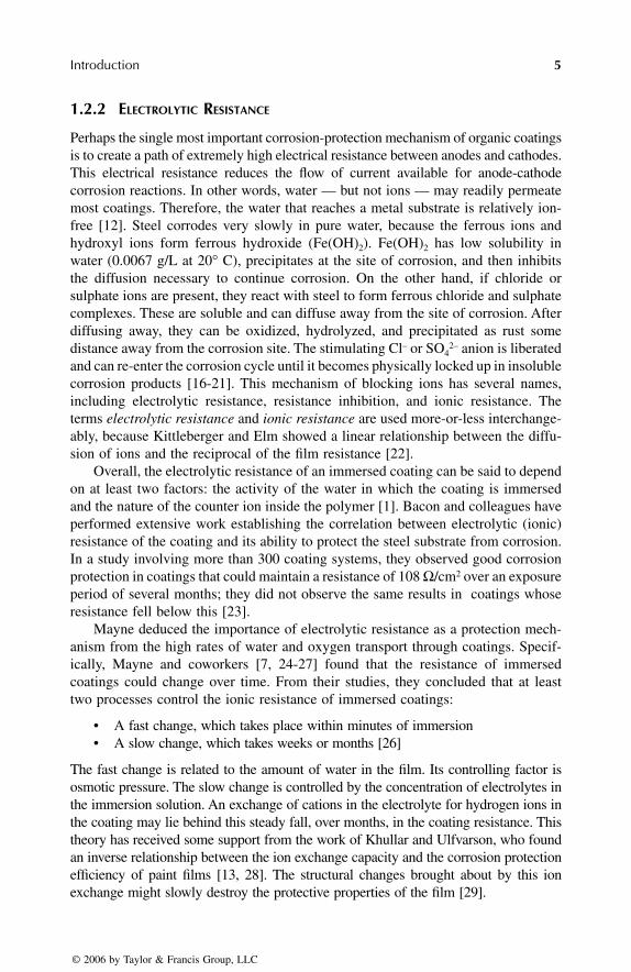
Perhaps the single most important corrosion-protection mechanism of organic coatingsis to create a path of extremely high electrical resistance between anodes and cathodes.This electrical resistance reduces the flow of current available for anode-cathodecorrosion reactions. In other words, water — but not ions — may readily permeatemost coatings. Therefore, the water that reaches a metal substrate is relatively ion-free [12]. Steel corrodes very slowly in pure water, because the ferrous ions andhydroxyl ions form ferrous hydroxide (Fe(OH)
2
). Fe(OH)
2
has low solubility inwater (0.0067 g/L at 20
°
C), precipitates at the site of corrosion, and then inhibitsthe diffusion necessary to continue corrosion. On the other hand, if chloride orsulphate ions are present, they react with steel to form ferrous chloride and sulphatecomplexes. These are soluble and can diffuse away from the site of corrosion. Afterdiffusing away, they can be oxidized, hydrolyzed, and precipitated as rust somedistance away from the corrosion site. The stimulating Cl
–
or SO
42–
anion is liberatedand can re-enter the corrosion cycle until it becomes physically locked up in insolublecorrosion products [16-21]. This mechanism of blocking ions has several names,including electrolytic resistance, resistance inhibition, and ionic resistance. Theterms
electrolytic resistance
and
ionic resistance
are used more-or-less interchange-ably, because Kittleberger and Elm showed a linear relationship between the diffu-sion of ions and the reciprocal of the film resistance [22].
Overall, the electrolytic resistance of an immersed coating can be said to dependon at least two factors: the activity of the water in which the coating is immersedand the nature of the counter ion inside the polymer [1]. Bacon and colleagues haveperformed extensive work establishing the correlation between electrolytic (ionic)resistance of the coating and its ability to protect the steel substrate from corrosion.In a study involving more than 300 coating systems, they observed good corrosionprotection in coatings that could maintain a resistance of 108
Ω
/cm
2
over an exposureperiod of several months; they did not observe the same results in coatings whoseresistance fell below this [23].
Mayne deduced the importance of electrolytic resistance as a protection mech-anism from the high rates of water and oxygen transport through coatings. Specif-ically, Mayne and coworkers [7, 24-27] found that the resistance of immersedcoatings could change over time. From their studies, they concluded that at leasttwo processes control the ionic resistance of immersed coatings:
• A fast change, which takes place within minutes of immersion• A slow change, which takes weeks or months [26]
The fast change is related to the amount of water in the film. Its controlling factor isosmotic pressure. The slow change is controlled by the concentration of electrolytes inthe immersion solution. An exchange of cations in the electrolyte for hydrogen ions inthe coating may lie behind this steady fall, over months, in the coating resistance. Thistheory has received some support from the work of Khullar and Ulfvarson, who foundan inverse relationship between the ion exchange capacity and the corrosion protectionefficiency of paint films [13, 28]. The structural changes brought about by this ionexchange might slowly destroy the protective properties of the film [29].
7278_C001.fm Page 5 Wednesday, March 1, 2006 10:54 AM
© 2006 by Taylor & Francis Group, LLC

6
Corrosion Control Through Organic Coatings
Many workers in the field of water transport have concentrated on the physicalproperties of film, such as capillary structure, or composition of the electrolytes.The work of Kumins and London has shown that the chemical composition of thepolymer is equally important. In particular, the concentration of fixed anions in thepolymer film is critical. They found that if the concentration of salt in the electrolytewas below the film’s fixed-anion concentration, the passage of anions through the filmwas very restricted. If the electrolyte’s concentration was above the polymer’s fixed-anion concentration, anions could permeate much more freely through the film [30].
Further information regarding the mechanisms of ion transport through the coatingfilm can be found in reviews by Koehler, Walter, and Greenfield and Scantlebury[1, 29, 31].
1.2.3 A
DHESION
When a metal substrate has corroded, the paint no longer adheres to it. Accordingly,corrosion workers commonly place heavy emphasis on the importance of adhesionof the organic coating to the metal substrate, and a great deal of energy has goneinto developing test methods for quantifying this adhesion.
1.2.3.1 What Adhesion Accomplishes
Very strong adhesion can help suppress corrosion by resisting the development ofcorrosion products, hydrogen evolution, or water build-up under the coating [32-35].In addition, by bonding to as many available active sites on the metal surface aspossible, the coating acts as an electrical insulator, thereby suppressing the formationof anode-cathode microcells among inhomogeneities in the surface of the metal.
The role of adhesion is to create the necessary conditions so that corrosion-protection mechanisms can work. A coating cannot passivate the metal surface,create a path of extremely high electrical resistance at the metal surface, or preventwater or oxygen from reaching the metal surface unless it is in intimate contact —at the atomic level — with the surface. The more chemical bonds between the surfaceand coating, the closer the contact and the stronger the adhesion. An irreverent viewcould be that the higher the number of sites on the metal that are taken up in bondingwith the coating, the lower the number of sites remaining available for electrochemicalmischief. Or as Koehler expressed it:
The position taken here is that from a corrosion standpoint, the degree of adhesion isin itself not important. It is only important that some degree of adhesion to the metalsubstrate be maintained. Naturally, if some external agency causes detachment of theorganic coating and there is a concurrent break in the organic coating, the coating willno longer serve its function over the affected area. Typically, however, the detachmentoccurring is the result of the corrosion processes and is not quantitatively related toadhesion [1].
In summary, good adhesion of the coating to the substrate could be described as a“necessary but not sufficient” condition for good corrosion protection. For all of theprotection mechanisms described in the previous sections, good adhesion of the coating
7278_C001.fm Page 6 Friday, February 3, 2006 12:34 PM
© 2006 by Taylor & Francis Group, LLC

Introduction
7
to the metal is a necessary condition. However, good adhesion alone is not enough;adhesion tests in isolation cannot predict the ability of a coating to control corrosion [36].
1.2.3.2 Wet Adhesion
A coating can be saturated with water, but if it adheres tightly to the metal, it canstill prevent sufficient amounts of electrolytes from collecting at the metal surfacefor the initiation of corrosion. How well the coating clings to the substrate when itis saturated is known as
wet adhesion
. Adhesion under dry conditions is probablyoverrated; wet adhesion, on the other hand, is crucial to corrosion protection.
Commonly, coatings with good dry adhesion have poor wet adhesion [37-41].The same polar groups on the binder molecules that create good dry adhesion canwreak mischief by decreasing water resistance at the coating-metal interface — thatis, they decrease wet adhesion [42]. Another important difference is that, once lost,dry adhesion cannot be recovered. Loss of adhesion in wet conditions, on the otherhand, can be reversible, although the original dry adhesion strength will probablynot be obtained [16, 43].
Perhaps it should be noted that wet adhesion is a coating property and not afailure mechanism. Permanent adhesion loss due to humid or wet circumstances alsoexists and is called
water disbondment.
Relatively little research has been done on wet adhesion phenomena. Leidheiserhas identified some important questions in this area [43]:
1. How can wet adhesion be quantitatively measured while the coating is wet?2. What is the governing principle by which water collects at the organic
coating-metal interface?3. What is the thickness of the water layer at the interface, and what deter-
mines this thickness?
Two additional questions could be added to this list:
4. What makes adhesion loss under wet circumstances irreversible? Is therea relationship between the coating property, wet adhesion, the failuremechanism, and water disbondment?
5. Why does the reduction of adhesion on exposure to water not lead tocomplete delamination? What causes residual adhesion in wet circum-stances?
As a possible answer to the last question above, Funke has suggested that dryadhesion is due to a mixture of bond types. Polar bonding, which is somewhatsensitive to water molecules, could account for reduced adhesion in wet circum-stances, whereas chemical bonds or mechanical locking may account for residualadhesion [16]. Further research on wet adhesion could answer some of the afore-mentioned questions and increase understanding of this complex mechanism.
1.2.3.3 Important Aspects of Adhesion
Two aspects of adhesion are important: the initial strength of the coating-substratebond and what happens to this bond as the coating ages.
7278_C001.fm Page 7 Friday, February 3, 2006 12:34 PM
© 2006 by Taylor & Francis Group, LLC
8
Corrosion Control Through Organic Coatings
A great deal of work has been done to develop better methods for measuringthe initial strength of the coating-substrate bond. Unfortunately, the emphasis onmeasuring initial adhesion may miss the point completely. It is certainly true thatgood adhesion between the metal and the coating is necessary for preventing cor-rosion under the coating. However, it is possible to pay too much attention tomeasuring the difference between very good initial adhesion and excellent initialadhesion, completely missing the question of whether or not that adhesion is main-tained. In other words, as long as the coating has good initial adhesion, then it doesnot matter whether that adhesion is simply very good or great. What matters is whathappens to the adhesion over time. This aspect is much more crucial to coatingsuccess or failure than is the exact value of the initial adhesion.
Adhesion tests on aged coatings are useful not only to ascertain if the coatingsstill adhere to the metal but also to yield information about the mechanisms ofcoating failure. This area deserves greater attention, because studying changes inthe failure loci in adhesion tests before and after weathering can yield a great dealof information about coating deterioration.
1.2.4 P
ASSIVATING
WITH
P
IGMENTS
Anticorrosion pigments in a coating dissolve in the presence of water. Their dissociatedions migrate to the coating-metal interface and passivate it by supporting the formationof thin layers of insoluble corrosion products, which inhibit further corrosion [44-46].For more information about anticorrosion pigments, see Chapter 2.
1.2.5 A
LTERNATIVE
A
NODES
(C
ATHODIC
P
ROTECTION
)
Some very effective anticorrosion coatings allow the conditions necessary for cor-rosion to occur — for example, water, oxygen, and ions may be present; the coatingdoes not offer much electrical resistance; or soluble pigments have not passivatedthe metal surface. These coatings do not protect by suppressing the corrosion process;rather, they provide another metal that will corrode instead of the substrate. Thismechanism is referred to as
cathodic protection.
In protective coatings, the mostimportant example of cathodic protection is zinc-rich paints, whose zinc pigmentacts as a sacrificial anode, corroding preferentially to the steel substrate. For moreinformation on zinc-rich coatings, see Chapter 2.
REFERENCES
1. Koehler, E.L.,
Corrosion under organic coatings,
Proc., U.R.. Evans InternationalConference on Localized Corrosion, NACE, Houston, 1971, 117.
2. Guruviah, S.,
JOCCA,
53, 669, 1970.3. Mayne, J.E.O.,
JOCCA,
32, 481, 1949.4. Thomas, A.M and Gent, W.L.,
Proc. Phys. Soc.,
57, 324, 1945.5. Anderson, A.P. and Wright, K.A.,
Industr. Engng. Chem.,
33, 991, 1941.6. Edwards, J.D. and Wray, R.I.,
Industr. Engng. Chem.,
28, 549, 19367. Maitland, C.C. and Mayne, J.E.O.,
Off. Dig.,
34, 972, 1962.8. McSweeney, E.E.,
Off. Dig.,
37, 626, 1965.
7278_C001.fm Page 8 Friday, February 3, 2006 12:34 PM
© 2006 by Taylor & Francis Group, LLC

Introduction
9
9. Thomas. N.L., Prog.
Org. Coat.,
19, 101, 1991. 10. Thomas, N.L., Proc. Symp. Advances in Corrosion Protection by Organic Coatings,
Electrochem. Soc.,
1989, 451.11. Haagen, H. and Funke, W.,
JOCCA,
58, 359. 1975.12. Wheat, N.,
Prot. Coat. Eur.,
3, 24, 1998.13. Khullar, M.L. and Ulfvarson, U., Proc., IXth FATIPEC Congress, Fédération d’Asso-
ciations de Techniciens des Industries des Peintures, Vernis, Emaux et Encresd’Imprimerie de l’Europe Continentale (FATIPEC), Paris, 1968, 165.
14. Bacon, C. et al.,
Ind. Eng. Chem.,
161, 40, 1948.15. Cherry, B.W.,
Australag. Corr. and Eng.,
10, 18, 1974.16. Funke, W., in
Surface Coatings – 2,
Wilson, A.D., Nicholson, J.W. and Prosser, H.J.,Eds., Elsevier Applied Science, London, 1988, 107.
17 Kaesche, H.,
Werkstoffe u. Korrosion,
15, 379, 1964.18. Knotkowa-Cermakova, A. and Vlekova, J.,
Werkstoffe u. Korrosion,
21, 16, 1970.19. Schikorr, G.,
Werkstoffe u. Korrosion,
15, 457, 1964.20. Dunkan, J.R.,
Werkstoffe u. Korrosion,
25, 420, 1974.21. Barton, K. and Beranek, E.,
Werkstoffe u. Korrosion,
10, 377, 1959.22. Kittleberger, W.W. and Elm, A.C.
Ind. Eng. Chem.,
44, 326, 1952.23. Bacon, C.R., Smith, J.J. and Rugg, F.M.,
Ind. Eng. Chem.,
40, 161, 1948.24. Cherry, B.W. and Mayne, J.E.O., Proc., First International Congress on Metallic
Corrosion, Butterworths, London, 1961.25. Mayne, J.E.O.,
Trans. Inst. Met. Finish.,
41, 121, 1964.26. Cherry, B.W. and Mayne, J.E.O.
Off. Dig.,
37, 13, 1965.27. Mayne, J.E.O.,
JOCCA,
40, 183, 1957.28. Ulfvarson, U. and Khullar, M.,
JOCCA,
54, 604, 1971.29. Walter, G.W.,
Corros. Science,
26, 27, 1986.30. Kumins, C.A. and London, A., J.
Polymer Science,
46, 395, 1960.31. Greenfield, D. and Scantlebury, D.,
J. Corros. Science and Eng.,
3, Paper 5, 2000.32. Patrick, R.L. and Millar, R.L. in
Handbook of Adhesives,
Skeist, I., Ed. ReinholdPublishing Corp., New York, 1962, 602.
33. Kittleberger, W.W. and Elm, A.C.,
Ind. Eng. Chem.,
38, 695, 1946.34. Evans, U.R.
Corrosion and Oxidation of Metals,
St. Martin’s Press, New York. 1960.35. Gowers, K.R. and Scantlebury, J.D.
JOCCA,
4, 114, 1988.36. Troyk, P.R., Watson, M.J. and Poyezdala, J.J., in ACS Symposium Series 322: Poly-
meric Materials for Corrosion Control, Dickie, R.A. and Floyd, F.L, Eds., AmericanChemical Society, Washington DC, 1986, 299.
37. Bullett, T.R.,
JOCCA,
46, 441, 1963.38. Walker, P.,
Off. Dig.,
37, 1561, 1965.39. Walker, P.,
Paint Technol.,
31, 22, 1967.40. Walker, P.,
Paint Technol.,
31, 15, 1967.41. Funke, W., J.
Coat. Technol.,
55, 31, 1983.42. Funke, W., in ACS Symposium Series 322: Polymeric Materials for Corrosion Control,
Dickie, R.A. and Floyd, F.L, Eds., American Chemical Society, Washington DC, 1986, 222.43. Leidheiser, H., in ACS Symposium Series 322: Polymeric Materials for Corrosion
Control, Dickie, R.A. and Floyd, F.L, Eds., American Chemical Society, WashingtonDC, 1986, 124.
44. Mayne, J.E.O. and Ramshaw, E.H. J.
Appl. Chem.,
13, 553, 1969.45. Leidheiser, H., J.
Coat. Technol.,
53, 29, 1981.46. Mayne, J.E.O., in
Pigment Handbook, Vol. III, Patton, T.C., Ed. Wiley IntersciencePubl., 1973, 457.
7278_C001.fm Page 9 Friday, February 3, 2006 12:34 PM
© 2006 by Taylor & Francis Group, LLC

11
2
Composition of the Anticorrosion Coating
2.1 COATING COMPOSITION DESIGN
Generally, the formulation of a coating may be said to consist of the binder,pigment, additives, and carrier. The binder and the pigment are the most importantelements; they may be said to perform the corrosion-protection work in the curedpaint.
With very few exceptions (e.g., inorganic zinc-rich primers [ZRPs]), binders areorganic polymers. A combination of polymers is frequently used, even if the coatingbelongs to one generic class. An acrylic paint, for example, may purposely useseveral acrylics derived from different monomers or from similar monomers withvarying molecular weights and functional groups of the final polymer. Polymerblends capitalize on each polymer’s special characteristics; for example, a methacry-late-based acrylic with its excellent hardness and strength should be blended witha softer polyacrylate to give some flexibility to the cured paint.
Pigments are added for corrosion protection, for color, and as filler. Anticorrosionpigments are chemically active in the cured coating, whereas pigments in barriercoatings must be inert. Filler pigments must be inert at all times, of course, and thecoloring of a coating should stay constant throughout its service life.
Additives may alter certain characteristics of the binder, pigment, or carrier toimprove processing and compatibility of the raw materials or application and cureof the coating.
The carrier is the vehicle in the uncured paint that carries the binder, thepigments, and the additives. It exists only in the uncured state. Carriers are liquidsin the case of solvent-borne and waterborne coatings, and gases in the case of powdercoatings.
2.2 BINDER TYPES
The binder of a cured coating is analogous to the skeleton and skin of the humanbody. In the manner of a skeleton, the binder provides the physical structure tosupport and contain the pigments and additives. It binds itself to these componentsand to the metal surface, hence its name. It also acts somewhat as a skin: the amountsof oxygen, ions, water, and ultraviolet (UV) radiation that can penetrate into thecured coating layer depend to some extent on which polymer is used. This is becausethe cured coating is a very thin polymer-rich or pure polymer layer over a hetero-geneous mix of pigment particles and binder. The thin topmost layer — sometimesknown as the
healed layer
of the coating — covers gaps between pigment particles
7278_C002.fm Page 11 Wednesday, March 1, 2006 10:55 AM
© 2006 by Taylor & Francis Group, LLC

12
Corrosion Control Through Organic Coatings
and cured binder, through which water finds its easiest route to the metal surface.It can also cover pores in the bulk of the coating, blocking this means of watertransport. Because this healed surface is very thin, however, its ability to entirelyprevent water uptake is greatly limited. Generally, it succeeds much better at limitingtransport of oxygen. The ability to absorb, rather than transmit, UV radiation ispolymer-dependent; acrylics, for example, are for most purposes impervious toUV-light, whereas epoxies are extremely sensitive to it.
The binders used in anticorrosion paints are almost exclusively organic polymers.The only commercially significant exceptions are the silicon-based binder in inor-ganic ZRPs sil oxanes, and high-temperature silicone coatings. Many of the coating’sphysical and mechanical properties — including flexibility, hardness, chemicalresistances, UV-vulnerability, and water and oxygen transport — are determinedwholly or in part by the particular polymer or blend of polymers used.
Combinations of monomers and polymers are commonly used, even if thecoating belongs to one generic polymer class. Literally hundreds of acrylics arecommercially available, all chemically unique; they differ in molecular weights,functional groups, starting monomers, and other characteristics. A paint formulatormay purposely blend several acrylics to take advantage of the characteristics of each;thus a methacrylate-based acrylic with its excellent hardness and strength might beblended with one of the softer polyacrylates to impart flexibility to the cured paint.
Hybrids, or combinations of different polymer families, are also used. Examplesof hybrids include acrylic-alkyd hybrid waterborne paints and the epoxy-modifiedalkyds known as epoxy ester paints.
2.2.1 E
POXIES
Because of their superior strength, chemical resistance, and adhesion to substrates,epoxies are the most important class of anticorrosive paint. In general, epoxies havethe following features:
• Very strong mechanical properties• Very good adhesion to metal substrates• Excellent chemical, acid, and water resistance• Better alkali resistance than most other types of polymers• Susceptibility to UV degradation
2.2.1.1 Chemistry
The term
epoxy
refers to thermosetting polymers produced by reaction of an epoxidegroup (also known as the glycidyl, epoxy, or oxirane group; see Figure 2.1). Thering structure of the epoxide group provides a site for crosslinking with protondonors, usually amines or polyamides [1].
FIGURE 2.1
Epoxide or oxirane group.
CO
C
7278_C002.fm Page 12 Wednesday, March 1, 2006 10:55 AM
© 2006 by Taylor & Francis Group, LLC

Composition of the Anticorrosion Coating
13
Epoxies have a wide variety of forms, depending on whether the epoxy resin(which contains the epoxide group) reacts with a carboxyl, hydroxyl, phenol, oramine curing agent. Some of the typical reactions and resulting polymers are shownin Figure 2.2. The most commonly used epoxy resins are [2]:
• Diglycidyl ethers of bisphenol A (DGEBA or Bis A epoxies)• Diglycidyl ethers of bisphenol F (DGEBF or Bis F epoxies) — used for
low-molecular-weight epoxy coatings• Epoxy phenol or cresol novolac multifunctional resins
Curing agents include [2]:
• Aliphatic polyamines• Polyamine adducts• Ketimines• Polyamides/amidoamines• Aromatic amines• Cycloaliphatic amines• Polyisocyanates
2.2.1.2 Ultraviolet Degradation
Epoxies are known for their susceptibility to UV degradation. The UV rays of thesun contain enough energy to break certain bonds in the polymeric structure of acured binder. As more and more bond breakage occurs in the top surface of thecured binder layer, the polymeric backbone begins to break down. Because thetopmost surface or “healed layer” of the cured coating contains only binder, theinitial result of the UV degradation is simply loss of gloss. However, as the degra-dation works downward through the coating layer, binder breakdown begins to freepigment particles. A fine powder consisting of pigment and fragments of bindercontinually forms on the surface of the coating. The powder is reminiscent of chalkdust, hence the name “chalking” for this breakdown process.
FIGURE 2.2
Typical reactions of the epoxide (oxirane) group to form epoxies.
RO
HC CH2 + HOOC R′ R CHOH
CH2OOC R′
RO
HC CH2 + H2N R′ R CHOH
CH2NH R′
RO
O
HC CH2
CH2
+ HO
RO
HC CH2 + HO
R′
R′ R
R CH
CHOH
OHCH2O R′
R′
7278_C002.fm Page 13 Wednesday, March 1, 2006 10:55 AM
© 2006 by Taylor & Francis Group, LLC

14
Corrosion Control Through Organic Coatings
Chalking also occurs to some extent with several other types of polymers. Itdoes not directly affect corrosion protection but is a concern because it eventuallyresults in a thinner coating. The problem is easily overcome with epoxies, however,by covering the epoxy layer with a coating that contains a UV-resistant binder.Polyurethanes are frequently used for this purpose because they are similar inchemical structure to epoxies but are not susceptible to UV breakdown.
2.2.1.3 Variety of Epoxy Paints
The resins used in the epoxy reactions described in section 2.2.1.1 are available in awide range of molecular weights. In general, as molecular weight increases, flexibility,adhesion, substrate wetting, pot life, viscosity, and toughness increase. Increasedmolecular weight also corresponds to decreased crosslink density, solvent resistance,and chemical resistance [2]. Resins of differing molecular weights are usually blendedto provide the balance of properties needed for a particular type of coating.
The number of epoxide reactions possible is practically infinite and has resultedin a huge variety of epoxy polymers. Paint formulators have taken advantage of thisvariability to provide epoxy paints with a wide range of physical, chemical, andmechanical characteristics. The term “epoxy” encompasses an extremely wide rangeof coatings, from very-low-viscosity epoxy sealers (for penetration of crevices) toexceptionally thick epoxy mastic coatings.
2.2.1.3.1 Mastics
Mastics are high-solids, high-build epoxy coatings designed for situations in whichsurface preparation is less than ideal. They are sometimes referred to as “surface tolerant”because they do not require the substrate to be cleaned by abrasive blasting to Sa2 1/2.Mastics can tolerate a lack of surface profile (for anchoring) and a certain amount ofcontamination (e.g., by oil) that would cause other types of paints to quickly fail.
Formulation is challenging, because the demands placed on this class can becontradictory. Because they are used on smoother and less clean surfaces, masticsmust have good wetting characteristics. At the same time, viscosity must be veryhigh to prevent sagging of the very thick wet film on vertical surfaces. Meeting bothof these requirements presents a challenge to the paint chemist.
Epoxy mastics with aluminium flake pigments have very low moisture permeationsand are popular both as spot primers or full coats. They can be formulated with weaksolvents and thus can be used over old paint. The lack of aggressive solvents in masticsmeans that old paints will not be destroyed by epoxy mastics. This characteristic isneeded for spot primers, which overlap old, intact paint at the edge of the spot to becoated. Mastics pigmented with aluminium flake are also used as full-coat primers.
Because of their very high dry film thickness, build-up of internal stress in thecoating during cure is often an important consideration in using mastic coatings.
2.2.1.3.2 Solvent-Free Epoxies
Another type of commonly used epoxy paint is the solvent-free, or 100% solid,epoxies. Despite their name, these epoxies are not completely solvent-free. Thelevels of organic solvents are very low, typically below 5%, which allows very highfilm builds and greatly reduces concerns about volatile organic compounds (VOCs).
7278_C002.fm Page 14 Wednesday, March 1, 2006 10:55 AM
© 2006 by Taylor & Francis Group, LLC

Composition of the Anticorrosion Coating
15
An interesting note about these coatings is that many of them generate significantamounts of heat upon mixing. The cross-linking is exothermic, and little solvent ispresent to take up the heat in vaporization [2].
2.2.1.3.3 Glass Flake Epoxies
Glass flake epoxy coatings are used to protect steel in extremely aggressive envi-ronments. When these coatings were first introduced, they were primarily used inoffshore applications. In recent years, however, they have been gaining acceptancein mainstream infrastructure as well. Glass flake pigments are large and very thin,which allows them to form many dense layers with a large degree of overlap betweenglass particles. This layering creates a highly effective barrier against moisture andchemical penetration because the pathway around and between the glass flakes isextremely long. The glass pigment can also confer increased impact and abrasionresistance and may aid in relieving internal stress in the cured coating.
2.2.1.3.4 Coal Tar Epoxies
Coal tar, or pitch, is the black organic resin left over from the distillation of coal.It is nearly waterproof and has been added to epoxy amine and polymide paints toobtain coatings with very low water permeability. It should be noted that coal tarproducts contain polynuclear aromatic compounds, which are suspected to be carci-nogenic. The use of coal tar coatings is therefore restricted or banned in some countries.
2.2.2 A
CRYLICS
Acrylics
is a term used to describe a large and varied family of polymers. Generalcharacteristics of this group include:
• Outstanding UV stability• Good mechanical properties, particularly toughness [3]
Their exceptional UV resistance makes acrylics particularly suitable for applicationsin which retention of clarity and color are important.
Acrylic polymers can be used in both waterborne and solvent-borne coatingformulations. For anticorrosion paints, the term
acrylic
usually refers to waterborneor latex formulations.
2.2.2.1 Chemistry
Acrylics are formed by radical polymerization. In this chain of reactions, an initiator— typically a compound with an azo link (
N=N
) or a peroxy link (
0–0
)— breaks down at the central bond, creating two free radicals. These free radicalscombine with a monomer, creating a larger free-radical molecule, which continuesto grow as it combines with monomers, until it either:
• Combines with another free radical (effectively canceling each other) • Reacts with another free radical: briefly meeting, transferring electrons and
splitting unevenly, so that one molecule has an extra hydrogen atom andone is lacking a hydrogen atom (a process known as disproportionation)
7278_C002.fm Page 15 Wednesday, March 1, 2006 10:55 AM
© 2006 by Taylor & Francis Group, LLC

16
Corrosion Control Through Organic Coatings
• Transfers the free radical to another polymer, a solvent, or a chain transferagent, such as a low-molecular-weight mercaptan to control molecularweight
This process, excluding transfer, is depicted in Table 2.1 [4].Some typical initiators used are listed here and shown in Figure 2.3.
• Azo di isobutyronitrile (AZDN)• Di benzoyl peroxide •
T
-butyl perbenzoate • Di
t
-butyl peroxide
Typical unsaturated monomers include:
• Methacrylic acid • Methyl methacrylate• Butyl methacrylate• Ethyl acrylate• 2-Ethyl hexyl acrylate
TABLE 2.1Main Reactions Occurring in Free Radical Chain Addition Polymerization
Radical PolymerizationI
=
Initiator; M
=
Monomer
Initiator breakdown
I:I
I
+
I
Initiation and propagation
I
+
M
n
I(M)
n
Termination by combination
I(M)
n
+
(M)
m
I
I(M)
m
+
n
I
Termination by disproportionation
I(M)
n
+
(M)
n
I
I(M)
n
−
1
+
n
(M
−
H)
+
I(M)
m
−
1
(M
+
H)
Data from:
Bentley, J., Organic film formers, in
Paint and Surface Coatings Theory and Practice
,Lambourne, R., Ed., Ellis Horwood Limited, Chichester, 1987.
FIGURE 2.3
Typical initiators in radical polymerization: A
=
AZDN; B
=
Di benzoyl peroxide;C
=
T
-butyl perbenzoate; D
=
Di
t
-butyl peroxide.
CH3 C N = N CCN
CO O
O O
O OC
CO
CN
CH3 CH3CH3
tBu
O OtBu tBu
A.
B.
C.
D.
7278_C002.fm Page 16 Wednesday, March 1, 2006 10:55 AM
© 2006 by Taylor & Francis Group, LLC

Composition of the Anticorrosion Coating
17
• 2-Hydroxy propyl methacrylate • Styrene • Vinyl acetate (see also Figure 2.4)
2.2.2.2 Saponification
Acrylics can be somewhat sensitive to alkali environments — such as those whichcan be created by zinc surfaces
[5]. This sensitivity is nowhere near as severe asthose of alkyds and is easily avoided by proper choice of copolymers.
Acrylics can be divided into two groups, acrylates and methacrylates, depend-ing on the original monomer from which the polymer was built. As shown inFigure 2.5, the difference lies in a methyl group attached to the backbone of thepolymer molecule of a methacrylate in place of the hydrogen atom found in theacrylate.
FIGURE 2.4
Typical unsaturated monomers: A = Methacrylic acid; B = Methyl methacrylate;C = Butyl methacrylate; D = Ethyl acrylate; E = 2-Ethyl hexyl acrylate; F = 2-Hydroxy propylmethacrylate; G = Styrene; H =Vinyl acetate.
FIGURE 2.5
Depiction of an acrylate (left) and a methacrylate (right) polymer molecule.
A.
B.
C.
D.
E.
F.
G.
H.
HOC CH2
CH3C
O
CH2
CH2CH
CH
C
C
CH2 CH2
CH2
CH2
CH2
CH
OH
O O
CH
CH
CH
C2H5
CH2OOC
CH2OOC
OOC
CH3CH3 C C
OO
CH2
CH3
CH3
CH3
CH3
CH3
C4H9
nBu C CO
O
HC )CH2(C OO R
CH3C )CH2(C OO R
7278_C002.fm Page 17 Wednesday, March 1, 2006 10:55 AM
© 2006 by Taylor & Francis Group, LLC

18
Corrosion Control Through Organic Coatings
Poly(methyl methacrylate) is quite resistant to alkaline saponification; the prob-lem lies with the polyacrylates [6]. However, acrylic emulsion polymers cannot becomposed solely of methyl methacrylate because the resulting polymer would havea minimum film formation temperature of over 100
°
C. Forming a film at roomtemperature with methyl methacrylate would require unacceptably high amounts ofexternal plasticizers or coalescing solvents. For paint formulations, acrylic emulsionpolymers must be copolymerized with acrylate monomers.
Acrylics can be successfully formulated for coating zinc or other potentially alkalisurfaces, if careful attention is given to the types of monomer used for copolymerization.
2.2.2.3 Copolymers
Most acrylic coatings are copolymers, in which two or more acrylic polymers areblended to make the binder. This practice combines the advantages of each polymer.Poly(methyl methacrylate), for example, is resistant to saponification, or alkalibreakdown. This makes it a highly desirable polymer for coating zinc substrates orany surfaces where alkali conditions may arise. Certain other properties of methylmethacrylate, however, require some modification from a copolymer in order to forma satisfactory paint. For example, the elongation of pure methyl methacrylate isundesirably low for both solvent-borne and waterborne coatings (see Table 2.2) [7].A “softer” acrylate copolymer is therefore used to impart to the binder the necessaryability to flex and bend. Copolymers of acrylates and methacrylates can give thebinder the desired balance between hardness and flexibility. Among other properties,acrylates give the coating improved cold crack resistance and adhesion to the sub-strate, whereas methacrylates contribute toughness and alkali resistance [3,4,6]. Inwaterborne formulations, methyl methacrylate emulsion polymers alone could notform films at room temperature without high amounts of plasticizers, coalescingsolvents, or both.
Copolymerization is also used to improve solvent and water release in thewet stage, and resistance to solvents and water absorption in the cured coating.Styrene is used for hardness and water resistance, and acrylonitrile impartssolvent resistance [3].
TABLE 2.2Mechanical Properties of Methyl Methacrylateand Polyacrylates
Methyl methacrylate Polyacrylates
Tensile strength (psi) 9000 3-1000Elongation at break 4% 750-2000%
Modified from: Brendley, W.H.,
Paint and Varnish Production,
63, 19, 1973.
7278_C002.fm Page 18 Wednesday, March 1, 2006 10:55 AM
© 2006 by Taylor & Francis Group, LLC

Composition of the Anticorrosion Coating
19
2.2.3 P
OLYURETHANES
Polyurethanes as a class have the following characteristics:
• Excellent water resistance [1]• Good resistance to acids and solvents• Better alkali resistance than most other polymers• Good abrasion resistance and, in general, good mechanical properties
They are formed by isocyanate (R–N=C=O) reactions, typically with hydroxylgroups, amines, or water. Some typical reactions are shown in Figure 2.6. Polyure-thanes are classified into two types, depending on their curing mechanisms: moisture-cure urethanes and chemical-cure urethanes [1]. These are described in more detailin subsequent sections. Both moisture-cure and chemical-cure polyurethanes can bemade from either aliphatic or aromatic isocyanates.
Aromatic
polyurethanes are made from isocyanates that contain unsaturatedcarbon rings, for example, toluene diisocyanate. Aromatic polyurethanes cure fasterdue to inherently higher chemical reactivity of the polyisocyanates [8], have morechemical and solvent resistance, and are less expensive than aliphatics but are moresusceptible to UV radiation [1,9,10]. They are mostly used, therefore, as primers orintermediate coats in conjunction with nonaromatic topcoats that provide UV pro-tection. The UV susceptibility of aromatic polyurethane primers means that the timethat elapses between applying coats is very important. The manufacturer’s recom-mendations for maximum recoat time should be carefully followed.
Aliphatic
polyurethanes are made from isocyanates that do not contain unsaturatedcarbon rings. They may have linear or cyclic structures; in cyclic structures, the ringis saturated [11]. The UV resistance of aliphatic polyurethanes is higher than that ofaromatic polyurethanes, which results in better weathering characteristics, such asgloss and color retention. For outdoor applications in which good weatherability isnecessary, aliphatic topcoats are preferable [1,9]. In aromatic-aliphatic blends, evensmall amounts of an aromatic component can significantly affect gloss retention [12].
FIGURE 2.6
Some typical isocyanate reactions. A-hydroxyl reaction; B-amino reaction;C-moisture core reaction.
R NCO HO R′+ OR′R NH
CO
(Urethane)
R NCO H2N R′+ NR′R NH H
CO
(Urea)
R NCO HOH+ +R NH2 CO2OHR NH
CO
(Carbamic acid)
A.
B.
C.
7278_C002.fm Page 19 Wednesday, March 1, 2006 10:55 AM
© 2006 by Taylor & Francis Group, LLC

20
Corrosion Control Through Organic Coatings
2.2.3.1 Moisture-Cure Urethanes
Moisture-cure urethanes are one-component coatings. The resin has at least twoisocyanate groups (–N=C=O) attached to the polymer. These functional groups reactwith anything containing reactive hydrogen, including water, alcohols, amines, ureas,and other polyurethanes. In moisture-cure urethane coatings, some of the isocyanatereacts with water in the air to form carbamic acid, which is unstable. This aciddecomposes to an amine which, in turn, reacts with other isocyanates to form a urea.The urea can continue reacting with any available isocyanates, forming a biuretstructure, until all the reactive groups have been consumed [9,11]. Because eachmolecule contains at least two –N=C=O groups, the result is a crosslinked film.
Because of their curing mechanism, moisture-cure urethanes are tolerant of dampsurfaces. Too much moisture on the substrate surface is, of course, detrimental,because isocyanate reacts more easily with water rather than with reactive hydrogenon the substrate surface, leading to adhesion problems. Another factor that limitshow much water can be tolerated on the substrate surface is carbon dioxide (CO
2
).CO
2
is a product of isocyanate’s reaction with water. Too rapid CO
2
production canlead to bubbling, pinholes, or voids in the coating [9].
Pigmenting moisture-cure polyurethanes is not easy because, like all additives,pigments must be free from moisture [9]. The color range is therefore somewhatlimited compared with the color range of other types of coatings.
2.2.3.2 Chemical-Cure Urethanes
Chemical-cure urethanes are two-component coatings, with a limited pot life aftermixing. The reactants in chemical-cure urethanes are:
1. A material containing an isocyanate group (–N=C=O)2. A substance bearing free or latent active hydrogen-containing groups (i.e.,
hydroxyl or amino groups) [8]
The first reactant acts as the curing agent. Five major monomeric diisocyanates arecommercially available [10]:
• Toluene diisocyanate (TDI)• Methylene diphenyl diisocyanate (MDI)• Hexamethylene diisocyanate (HDI)• Isophorone diisocyanate (IPDI)• Hydrogenated MDI (H
12
MDI)
The second reactant is usually a hydroxyl-group-containing oligomer from theacrylic, epoxy, polyester, polyether, or vinyl classes. Furthermore, for each of theaforementioned oligomer classes, the type, molecular weight, number of cross-linkingsites, and glass transition temperature of the oligomer affect the performance of thecoating. This results in a wide range of properties possible in each class of polyurethanecoating. The performance ranges of the different types of urethanes overlap, but somebroad generalization is possible. Acrylic urethanes, for example, tend to have superiorresistance to sunlight, whereas polyester urethanes have better chemical resistance[1,10]. Polyurethane coatings containing polyether polyols generally have better
7278_C002.fm Page 20 Wednesday, March 1, 2006 10:55 AM
© 2006 by Taylor & Francis Group, LLC
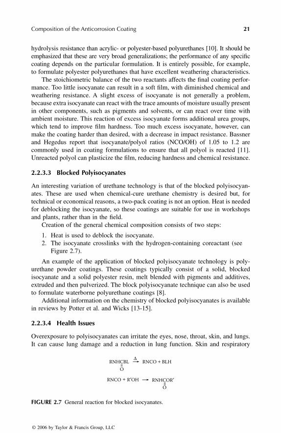
Composition of the Anticorrosion Coating
21
hydrolysis resistance than acrylic- or polyester-based polyurethanes [10]. It should beemphasized that these are very broad generalizations; the performance of any specificcoating depends on the particular formulation. It is entirely possible, for example,to formulate polyester polyurethanes that have excellent weathering characteristics.
The stoichiometric balance of the two reactants affects the final coating perfor-mance. Too little isocyanate can result in a soft film, with diminished chemical andweathering resistance. A slight excess of isocyanate is not generally a problem,because extra isocyanate can react with the trace amounts of moisture usually presentin other components, such as pigments and solvents, or can react over time withambient moisture. This reaction of excess isocyanate forms additional urea groups,which tend to improve film hardness. Too much excess isocyanate, however, canmake the coating harder than desired, with a decrease in impact resistance. Bassnerand Hegedus report that isocyanate/polyol ratios (NCO/OH) of 1.05 to 1.2 arecommonly used in coating formulations to ensure that all polyol is reacted [11].Unreacted polyol can plasticize the film, reducing hardness and chemical resistance.
2.2.3.3 Blocked Polyisocyanates
An interesting variation of urethane technology is that of the blocked polyisocyan-ates. These are used when chemical-cure urethane chemistry is desired but, fortechnical or economical reasons, a two-pack coating is not an option. Heat is neededfor deblocking the isocyanate, so these coatings are suitable for use in workshopsand plants, rather than in the field.
Creation of the general chemical composition consists of two steps:
1. Heat is used to deblock the isocyanate.2. The isocyanate crosslinks with the hydrogen-containing coreactant (see
Figure 2.7).
An example of the application of blocked polyisocyanate technology is poly-urethane powder coatings. These coatings typically consist of a solid, blockedisocyanate and a solid polyester resin, melt blended with pigments and additives,extruded and then pulverized. The block polyisocyanate technique can also be usedto formulate waterborne polyurethane coatings [8].
Additional information on the chemistry of blocked polyisocyanates is availablein reviews by Potter et al. and Wicks [13-15].
2.2.3.4 Health Issues
Overexposure to polyisocyanates can irritate the eyes, nose, throat, skin, and lungs.It can cause lung damage and a reduction in lung function. Skin and respiratory
FIGURE 2.7
General reaction for blocked isocyanates.
RNHCBL
RNCO R′OH
RNCO
RNHCOR′
BLHO
O
∆
+
+
7278_C002.fm Page 21 Wednesday, March 1, 2006 10:55 AM
© 2006 by Taylor & Francis Group, LLC

22
Corrosion Control Through Organic Coatings
sensitization resulting from overexposure can result in asthmatic symptoms that maybe permanent. Workers must be properly protected when mixing and applyingpolyurethanes as well as when cleaning up after paint application. Inhalation, skincontact, and eye contact must be avoided. The polyurethane coating supplier shouldbe consulted about appropriate personal protective equipment for the formulation.
2.2.4.5 Waterborne Polyurethanes
For many years, it was thought that urethane technology could not effectively beused for waterborne systems because isocyanates react with water. In the past twentyyears, however, waterborne polyurethane technology has evolved tremendously, andin the past few years, two-component waterborne polyurethane systems haveachieved some commercial significance.
For information on the chemistry of two-component waterborne polyurethanetechnology, the reader should see the review of Wicks et al. [16]. A very good reviewof the effects of two-component waterborne polyurethane formulation on coatingproperties and application is available from Bassner and Hegedus [11].
2.2.4 P
OLYESTERS
Polyester and vinyl ester coatings have been used since the 1960s. Their character-istics include:
• Good solvent and chemical resistance, especially acid resistance (polyes-ters often maintain good chemical resistance at elevated temperatures [17])
• Vulnerability to attack of the ester linkage under strongly alkaline condi-tions
Because polyesters can be formulated to tolerate very thick film builds, they arepopular for lining applications. As thin coatings, they are commonly used for coil-coated products.
2.2.4.1 Chemistry
“Polyester” is a very broad term that encompasses both thermoplastic and thermo-setting polymers. In paint formulations, only thermosetting polyesters are used.Polyesters used in coatings are formed through:
1. Condensation of an alcohol and an organic acid, forming an ester — Thisis the unsaturated polyester prepolymer. It is dissolved in an unsaturatedmonomer (usually styrene or a similar vinyl-type monomer) to form a resin.
2. Crosslinking of the polyester prepolymer using the unsaturated monomer— A peroxide catalyst is added to the resin so that a free radical additionreaction can occur, transforming the liquid resin into a solid film [17].
A wide variety of polyesters are possible, depending on the reactants chosen. Themost commonly used organic acids are isophthalic acid, orthophthalic anhydride,
7278_C002.fm Page 22 Wednesday, March 1, 2006 10:55 AM
© 2006 by Taylor & Francis Group, LLC

Composition of the Anticorrosion Coating
23
terephthalic acid, fumaric acid, and maleic acid. Alcohol reactants used in conden-sation include bisphenol A, neopentyl glycol, and propylene glycol [17]. The com-binations of alcohol and organic acids used determine the mechanical and chemicalproperties, thermal stability, and other characteristics of polyesters.
2.2.4.2 Saponification
In an alkali environment, the ester links in a polyester can undergo hydrolysis —that is, the bond breaks and reforms into alcohol and acid. This reaction is notfavored in acidic or neutral environments but is favored in alkali environmentsbecause the alkali forms a salt with the acid component of the ester. These fatty acidsalts are called
soaps,
and hence this form of polymer degradation is known as
saponification.
The extent to which a particular polyester is vulnerable to alkali attack dependson the combination of reactants used to form the polyester prepolymer and theunsaturated monomer with which it is crosslinked.
2.2.4.3 Fillers
Fillers are very important in polyester coatings because these resins are unusuallyprone to build up of internal stresses. The stresses in cured paint films arise for tworeasons: shrinkage during cure and a high coefficient of thermal expansion.
During cure, polyester resins typically shrink a relatively high amount, 8 to 10volume percent [17]. Once the curing film has formed multiple bonds to the substrate,however, shrinkage can freely occur only in the direction perpendicular to thesubstrate. Shrinkage is hindered in the other two directions (parallel to the surfaceof the substrate), thus creating internal stress in the curing film. Fillers and rein-forcements are used to help avoid brittleness in the cured polyester film.
Stresses also arise in polyesters due to their high coefficients of thermal expan-sion. Values for polyesters are in the range of 36 to 72
×
10
–6
mm/mm/
°
C, whereasthose for steel are typically only 11
×
10
–6
mm/mm/
°
C [17]. Fillers and reinforce-ments are important for minimizing the stresses caused by temperature changes.
2.2.5 A
LKYDS
In commercial use since 1927 [18], alkyd resins are among the most widely usedanticorrosion coatings. They are one-component air-curing paints and, therefore, arefairly easy to use. Alkyds are relatively inexpensive. Alkyds can be formulated intoboth solvent-borne and waterborne coatings.
Alkyd paints are not without disadvantages:
• After cure, they continue to react with oxygen in the atmosphere, creatingadditional crosslinking and then brittleness as the coating ages [18].
• Alkyds cannot tolerate alkali conditions; therefore, they are unsuitable forzinc surfaces or any surfaces where an alkali condition can be expectedto occur, such as concrete.
7278_C002.fm Page 23 Wednesday, March 1, 2006 10:55 AM
© 2006 by Taylor & Francis Group, LLC

24
Corrosion Control Through Organic Coatings
• They are somewhat susceptible to UV radiation, depending on the specificresin composition [18].
• They are not suitable for immersion service because they lose adhesionto the substrate during immersion in water [18].
In addition, it should be noted that alkyd resins generally exhibit poor barrierproperties against moisture vapor. Choosing an effective anticorrosion pigment istherefore important for this class of coating [1].
2.2.5.1 Chemistry
Alkyds are a form of polyester. The main acid ingredient in an alkyd is phthalicacid or its anhydride, and the main alcohol is usually glycerol [18]. Through acondensation reaction, the organic acid and the alcohol form an ester. When thereactants contain multiple alcohol and acid groups, a crosslinked polymer resultsfrom the condensation reactions [18].
2.2.5.2 Saponification
In an alkali environment, the ester links in an alkyd break down and reform intoalcohol and acid, (see 2.2.4.2)
.
The known propensity of alkyd coatings to saponifymakes them unsuitable for use in alkaline environments or over alkaline surfaces.Concrete, for example, is initially highly alkaline, whereas certain metals, such aszinc, become alkaline over time due to their corrosion products.
This property of alkyds should also be taken into account when choosing pig-ments for the coating. Alkaline pigments such as red lead or zinc oxide can usefullyreact with unreacted acid groups in the alkyd, strengthening the film; however, thiscan also create shelf-life problems, if the coating gels before it can be applied.
2.2.5.3 Immersion Behavior
In making an alkyd resin, an excess of the alcohol reagent is commonly used, forreasons of viscosity control. Because alcohols are water-soluble, this excess alcoholmeans that the coating contains water-soluble material and therefore tends to absorbwater and swell [18]. Therefore, alkyd coatings tend to lose chemical adhesion tothe substrates when immersed in water. This process is usually reversible. As Byrnesdescribes it, “They behave as if they were attached to the substrate by water-solubleglue [18]”. Alkyd coatings are therefore not suitable for immersion service.
2.2.5.4 Brittleness
Alkyds cure through a reaction of the unsaturated fatty acid component withoxygen in the atmosphere. Once the coating has dried, the reaction does not stopbut continues to crosslink. Eventually, this leads to undesirable brittleness as thecoating ages, leaving the coating more vulnerable to, for example, freeze-thawstresses.
7278_C002.fm Page 24 Wednesday, March 1, 2006 10:55 AM
© 2006 by Taylor & Francis Group, LLC

Composition of the Anticorrosion Coating 25
2.2.5.5 Darkness Degradation
Byrnes notes an interesting phenomenon in some alkyds: if left in the dark for along time, they become soft and sticky. This reaction is most commonly seen inalkyds with high linseed oil content [18]. The reason why light is necessary formaintaining the cured film is not clear.
2.2.6 CHLORINATED RUBBER
Chlorinated rubber is commonly used for its barrier properties. It has very lowmoisture vapor transmission rates and also performs well under immersion condi-tions. General characteristics of these coatings are:
• Very good water and vapor barrier properties• Good chemical resistance but poor solvent resistance• Poor heat resistance• Comparatively high levels of VOCs [1,19]• Excellent adhesion to steel [19]
Chlorinated rubber coatings have been more popular in Europe than in NorthAmerica. In both markets, however, they are disappearing due to increasing pressureto eliminate VOCs.
2.2.6.1 Chemistry
The chemistry of chlorinated rubber resin is simple: polyisoprene rubber is chlori-nated to a very high content, approximately 65% [19]. It is then dissolved in solvents,typically a mixture of aromatics and aliphatics, such as xylene or VM&P naphtha[19]. Because of the high molecular weight of the polymers used, large amounts ofsolvent are needed. Chlorinated rubber coatings have low solids contents, in the 15%to 25% (vol/vol) range.
Chlorinated rubber coatings are not crosslinked; the resin undergoes no chemicalreaction during cure [1]; they are cured by solvent evaporation; in effect, the filmis formed by precipitation. However, the chlorine on the rubber molecule undergoeshydrogen bonding. The tight bonding of these secondary forces gives the coatingvery low moisture and oxygen transmission properties.
Because the film is formed by precipitation, chlorinated rubber coatings are veryvulnerable to attack by the solvents used in their formulation and have poor resistanceto nearly all other solvents. They are also vulnerable to attach by organic carboxylicacids, such as acetic and formic acids [19].
2.2.6.2 Dehydrochlorination
Chlorinated rubber resins tend to undergo dehydrochlorination; that is, a hydrogenatom on one segment of the polymer molecule joins with a chlorine atom on anadjacent segment to form hydrogen chloride. When they split off from the polymermolecule, a double bond forms in their place. In the presence of heat and light, this
7278_C002.fm Page 25 Wednesday, March 1, 2006 10:55 AM
© 2006 by Taylor & Francis Group, LLC

26 Corrosion Control Through Organic Coatings
double bond can crosslink, leading to film embrittlement. The hydrogen chloridealso is a problem; in the presence of moisture, it is a source of chloride ions, whichof course can initiate corrosion. The hydrogen chloride can also catalyze furtherbreakdown of the resin [19].
Dehydrochlorination is increased by exposure to heat and light. Therefore,chlorinated rubber coatings are not suitable for use in high-temperature applications.Sensitivity to light, however, can be nullified by pigmentation.
2.2.7 OTHER BINDERS
Other types of binders include epoxy esters and silicon-based inorganic zinc-richcoatings.
2.2.7.1 Epoxy esters
Despite their name, epoxy esters are not really epoxies. Appleman, in fact, writes thatepoxy esters “are best described as an epoxy-modified alkyd [20].” They are made bymixing an epoxy resin with either an oil (drying or vegetable) or a drying oil acid.The epoxy resin does not crosslink in the manner of conventional epoxies. Instead,the resin and oil or drying oil acid are subjected to high temperature, 240°C to 260°Cand an inert atmosphere to induce an esterification reaction. The result is a binder thatcures by oxidation and can therefore be formulated into one-component paints.
Epoxy esters generally possess adhesion, chemical and UV resistance, andcorrosion protection properties that are somewhere between those of alkyds andepoxies [21]. They also exhibit resistance to splashing of gasoline and other petro-leum fuels and are therefore commonly used to paint machinery [18].
2.2.7.2 Silicon-Based Inorganic Zinc-Rich Coatings
Silicon-based inorganic zinc-rich coatings are almost entirely zinc pigment; zinclevels of 90% or higher are common. They contain only enough binder to keep thezinc particles in electrical contact with the substrate and each other. The binder ininorganic ZRPs is an inorganic silicate, which may be either a solvent-based, partlyhydrolyzed alkyl silicate (typically ethyl silicate) or a water-based, highly-alkalisilicate.
General characteristics of these coatings are:
• Ability to tolerate higher temperatures than organic coatings (inorganicZRPs typically tolerate 700° to 750°F)
• Excellent corrosion protection• Require topcoatings in high pH or low pH conditions• Require a very thorough abrasive cleaning of the steel substrate, typically
near-white metal (SSPC grade SP10)
For a more-detailed discussion of inorganic ZRPs, see Section 2.3.5, “Zinc Dust.”
7278_C002.fm Page 26 Wednesday, March 1, 2006 10:55 AM
© 2006 by Taylor & Francis Group, LLC

Composition of the Anticorrosion Coating 27
2.3 CORROSION-PROTECTIVE PIGMENTS
2.3.1 TYPES OF PIGMENTS
Pigments come in three major types: inhibitive, sacrificial, and barrier. Coatingsutilizing inhibitive pigments release a soluble species, such as molybdates or phos-phates, from the pigment into any water that penetrates the coating. These speciesare carried to the metal surface, where they inhibit corrosion by encouraging thegrowth of protective surface layers [22]. Solubility and reactivity are critical param-eters for inhibitive pigments; a great deal of research is occupied with controllingthe former and decreasing the latter. Sacrificial pigments require zinc in large enoughquantities to allow the flow of electric current. When in electrical contact with thesteel surface, the zinc film acts as the anode of a large corrosion cell and protectsthe steel cathode. Both inhibitive and sacrificial pigments are effective only in thelayer immediately adjacent to the steel (i.e., the primer). Barrier coatings are prob-ably the oldest type of coating [22] and the requirements of their pigments arecompletely different. Specifically, chemical inertness and a flake- or plate-like shapeare the requirements of barrier pigments. Unlike inhibitive or sacrificial coatings,barrier coatings can be used as primer, intermediate coat, or topcoat because theirpigments do not react with metal.
2.3.1.1 A Note on Pigment Safety
The toxicity of lead, chromium, cadmium, and barium has made the continued useof paints containing these elements highly undesirable. The health and environmentalproblems associated with these heavy metals are serious, and new problems arediscovered all the time. To address this issue, pigment manufacturers have developedmany alternative pigments, such as zinc phosphates, calcium ferrites, and aluminumtriphosphates, to name a few. The number of proposed alternatives is not lacking;in fact, the number and types available are nearly overwhelming.
This chapter explores the major classes of pigments currently available foranticorrosion coating. The alert reader will quickly note that lead and barium aredescribed here, although use of these elements can no longer be recommended. Thisdiscussion is included for two reasons. First, the protective mechanism of red leadis highly relevant to evaluating new pigments because new pigments are inevitablycompared to lead. Second, the toxicity of soluble barium is less widely known thanthe toxicities of lead, chromium, and cadmium; therefore, barium is included hereto point out that it should be avoided.
2.3.2 LEAD-BASED PAINT
The inhibitive mechanism of the red lead found in lead-based paint (LBP) is complex.Lead pigments may be thought of as indirect inhibitors because, although theythemselves are not inhibitive, they undergo a reaction with select resin systems andthis reaction can form by-products that are active inhibitors [23].
7278_C002.fm Page 27 Wednesday, March 1, 2006 10:55 AM
© 2006 by Taylor & Francis Group, LLC

28 Corrosion Control Through Organic Coatings
2.3.2.1 Mechanism on Clean (New) Steel
Appleby and Mayne [24,25] have shown that formation of lead soaps is the mechanismused for protecting clean (or new) steel. When formulated with linseed oil, lead reactswith components of the oil to form soaps in the dry film; these soaps degrade to,among other things, the water-soluble salts lead of a variety of mono- and di-basicaliphatic acids [26,27]. Mayne and van Rooyen also showed that the lead salts ofazelaic, suberic, and pelargonic acid were inhibitors of the iron corrosion. Applebyand Mayne have suggested that these acids inhibit corrosion by bringing about theformation of insoluble ferric salts, which reinforce the air-formed oxide film until itbecomes impermeable to ferrous ions. This finding was based on experiments in whichpure iron was immersed in a lead azelate solution, with the thickness of the oxide filmmeasured before and after immersion. They found that the oxide film increased 7%to 17% in thickness upon immersion [25,28].
The lead salt of azelaic acid dissociates in water into a lead ion and an azelate ion.To determine which element was the key in corrosion inhibition, Appleby and Maynealso repeated the experiment with calcium azelate and sodium azelate [24,132]. Inter-estingly, they did not see a similar thickening of the oxide film when iron was immersedin calcium azelate and sodium azelate solutions, demonstrating that lead itself — notjust the organic acid — plays a role in protecting the iron. The authors note that 5 to20 ppm lead azelate in water is enough to prevent attack of pure iron immersed in thesolution. They note that, at this low concentration, inhibition cannot be caused by therepair of the air-formed oxide film by the formation of a complex azelate, as is the casein more concentrated solutions; rather, it appears to be associated with the thickeningof the air-formed oxide film. ‘‘It seems possible that, initially, lead ions in solution mayprovide an alternative cathodic reaction to oxygen reduction, and then, on being reducedto metallic lead at the cathodic areas on the iron surface, depolarize the oxygen reductionreaction, thus keeping the current density sufficiently high to maintain ferric filmformation. In addition any hydrogen peroxide so produced may assist in keeping theiron ions in the oxide film in the ferric condition, so that thickening of the air-formedfilm takes place until it becomes impervious to iron ions” [25].
2.3.2.2 Mechanism on Rusted Steel
Protecting rusted steel, rather than clean or new steel, may demand of a paint adifferent corrosion mechanism, simply because the paint is not applied directly tothe steel that must be protected but rather to the rust on top of it. Inhibitive pigmentsin the paint that require intimate contact with the metallic surface in order to protectit may therefore not perform well when a layer of rust prevents that immediatecontact. Red-lead paint, however, does perform well on rusted steel. Several theoriesabout the protective mechanism of red-lead paint on rusted steel exist.
2.3.2.2.1 Rust Impregnation TheoryAccording to this theory, the low viscosity of the vehicle used in LBP allows it topenetrate the surface texture of rust. This would have several advantages:
• Impregnation of the rust means that it is isolated and thereby inhibited inits corroding effect.
7278_C002.fm Page 28 Wednesday, March 1, 2006 10:55 AM
© 2006 by Taylor & Francis Group, LLC

Composition of the Anticorrosion Coating 29
• Oil-based penetrants provide a barrier effect, thus screening the rust fromwater and oxygen and slowing down corrosion [29].
• Good penetration and wetting of the rust by the paint results in betteradhesion.
Thomas examined cross-sections of LBP and other paints on rusted steel usingtransmission electron microscopy [30,31]; she found that, although the paint pene-trated well into cracks in the rust layer, there was no evidence that the LBP penetratedthrough the compact rust layers to the rust-metal interface. (It should be noted thatthis experiment used cooked linseed oil, not raw; Thomas notes that raw linseed oilhas a lower viscosity and might have penetrated further.) Where lead was found, itwas always in the vicinity of the paint-rust interface, and in low concentrations. Ithad presumably diffused into the rust layer after dissolution or breakdown of thered lead pigment and was not present as discrete particles of Pb3O4. Thomas alsofound that the penetration of LBP into the rust layer wasn’t significantly better thanthat of the other vehicles studied, for example, aluminium epoxy mastic. Finally,the penetration rate of water through linseed-oil based LBP was found to be approx-imately 214 g/m2/day for a 25-micron film and that of oxygen was 734 cc/m2/dayfor a 100-micron film [30]. The amounts of water and oxygen available through thepaint film are greater than the minimum needed for the corrosion of uncoated steel.Therefore, barrier properties can be safely eliminated as the protective mechanism.Superior penetration and wetting do not appear to be the mechanisms by which LBPprotects rusted steel.
2.3.2.2.2 Insolubilization of Sulfate and Chloride TheoryLBP may protect rusty steel by insolubilizing sulfate and chloride, rendering theseaggressive ions inert. Soluble ferrous salts are converted into stable, insoluble,and harmless compounds; for example, sulphate nests can be rendered ‘‘harmless”by treatment with barium salts because barium sulphate is extremely insoluble.This was suggested as a protective mechanism of LBP by Lincke and Mahn [32]because, when red-lead pigmented films were soaked in concentrated solutions ofFe(II) sulfate, Fe(III) sulfate, and Fe(III) chloride, precipitation reactions occurred.Thomas [33,34] tested this theory by examining cross-sections of LBP on rustedsteel (after 3 years’ exposure of the coated samples) using laser microprobe massspectrometry (LAMMS) and transmission electron microscopy with energy dis-persive x-ray. Low levels of lead were found in the rust layer, but only within30 µm of the rust-paint interface. Lead was neither seen at or near the rust-metalinterface, where sulfate nests are known to exist, nor was it distributed throughoutthe rust layer, even though sulfur was. If rendering inert is truly the mechanism,PbSO4 would be formed as the insoluble ‘‘precipitate” within the film, and theratio of Pb to S would be 1.0 or greater (assuming a surplus of lead exists).However, no correlation was seen between the distribution of lead and that ofsulfur (confirmed as sulfate by x-ray photo-electron spectroscopy); the ratio oflead to sulfur was 0.2 to 1.0, which Thomas concludes is insufficient to protectthe steel. Sulfate insolubilization does not, therefore, seem to be the mechanismby which LBP protects rusted steel.
7278_C002.fm Page 29 Wednesday, March 1, 2006 10:55 AM
© 2006 by Taylor & Francis Group, LLC

30 Corrosion Control Through Organic Coatings
2.3.2.2.3 Cathodic Inhibition TheoryIn the previously described work, low levels of lead were found in the rust layernear the paint-rust interface, within 30 µm of the rust-paint interface. Thomassuggests that because lead salts do not appear to reach the metal substrate to inhibitthe anodic reaction, it is possible that lead acts within the rust layer to slow downatmospheric corrosion by interfering with the cathodic reaction (i.e., by inhibitingthe cathodic reduction of existing rust [principally FeOOH to magnetite]) [33]. Thispresumably would suppress the anodic dissolution of iron because that reactionought to be balanced by the cathodic reaction. No conclusive proof for or againstthis theory has been offered.
2.3.2.2.4 Lead Soap/Lead Azelate TheoryThomas looked for lead (as a constituent of lead azelate) at the steel-rust interfacein an attempt to confirm this theory. Samples coated with lead-based paint wereexposed for three years and then cross-sections were examined in a LAMMS;however, lead was not detected at the interface. As Thomas points out, this findingdoes not eliminate the mechanism as a possibility; lead could still be present but inlevels below the 100 ppm detection limit of the LAMMS [30,31]. Appleby andMayne have shown that 5 to 20 ppm of lead azelate is enough to protect pure iron[25]. The levels needed to protect rusted steel would not be expected to be so low,because the critical concentration required for anodic inhibitors is higher whenchloride or sulphate ions are present than when used on new or clean steel [35].Possibly, a level between 20 and 100 ppm of lead azelate is sufficient to protect thesteel. Another point worth considering is that the amounts of lead that would existin the passive film formed by complex azelates, suggested by Appleby and Mayne,has not been determined. The lead soaps/lead azelate theory appears to be the mostlikely mechanism to explain how red-lead paints protect rusted steel.
2.3.2.3 Summary of Mechanism Studies
Formation of lead soaps appears to be the mechanism by which lead-based paintsinhibit corrosion of clean steel. When formulated with linseed oil, lead reacts withcomponents of the oil to form soaps in the cured film; in the presence of water andoxygen, these soaps degrade to, among other things, salts of a variety of mono- anddi-basic aliphatic acids. The lead salts of azelaic, suberic, and pelargonic acid actas corrosion inhibitors; lead azelate is of particular importance in LBP. These acidsmay inhibit corrosion by bringing about the formation of insoluble ferric salts, whichreinforce the metal’s oxide film until it becomes impermeable to ferrous ions, thussuppressing the corrosion mechanism.
The formation of lead soaps is believed to be the critical corrosion-protectionstep for both new (clean) steel and rusted steel.
2.3.2.4 Lead-Based Paint and Cathodic Potential
Chen et al. tested red lead in an alkyd binder in both open circuit conditions and undercathodic protection. They found that this coating gave excellent service in open circuitconditions, with almost no corrosion and minimal blistering. At –1000 mV Standard
7278_C002.fm Page 30 Wednesday, March 1, 2006 10:55 AM
© 2006 by Taylor & Francis Group, LLC

Composition of the Anticorrosion Coating 31
Calomel electrode (SCE), however, the same coating performed disastrously, withmassive blistering and disbonding (but no corrosion). The alkyd binder with nopigment at all performed better when cathodically polarized. They suggest that, atthe cathodic potential, metallic lead is deposited on the steel surface from the leadsoaps. When oxygen is reduced on this lead, it produces peroxides and radicals,which the authors suggested caused disbonding at the paint-metal interface [36].
2.3.3 PHOSPHATES
‘‘Phosphates” is a term that is used to refer to a large group of pigments that containa phosphorus and an oxygen functional group. Its meaning is vast: the term ‘‘zincphosphates” alone includes, but is not limited to:
• Zinc phosphate, first generation Zn3(PO4)2 •4H2O • Aluminum zinc phosphate [37] or zinc aluminum phosphate [38]• Zinc molybdenum phosphate• Aluminium-zinc hydroxyphosphate [38]• Zinc hydroxymolybdate-phosphate or basic zinc molybdate-phosphate
[38,39]• Basic zinc phosphate Zn2(OH)PO4•2H2O [38,39]• Zinc silicophosphate [23]• Zinc aluminum polyphosphate [38]
Zinc-free phosphates include:
• Aluminum phosphate• Dihydrogen tripolyphosphates [39]• Dihydrogen aluminium triphosphate [23,37,39,40]• Strontium aluminum polyphosphate [38]• Calcium aluminum polyphosphate silicate [38]• Zinc calcium strontium polyphosphate silicate [38]• Laurylammonium phosphate [41]• Hydroxyphosphates of iron, barium, chromium, cadmium, and magne-
sium, for example, FePO4•2H2O, Ca3(PO4)2-1/2H2O, Ba3(PO4)2, BaHPO4,and FeNH4PO4•2H2O [37]
In this section, the pigments discussed in more detail include the zinc phosphatesand one type of nonzinc phosphate, aluminium triphosphates.
2.3.3.1 Zinc Phosphates
Zinc phosphates are widely used in many binders, including oil-based binders,alkyds, and epoxies [41–50]. Their low solubility and activity make them extremelyversatile; they can be used in resins, such as alkyds, where more alkali pigmentspose stability problems. Typical loading levels are 10% to 30% in maintenancecoatings.
7278_C002.fm Page 31 Wednesday, March 1, 2006 10:55 AM
© 2006 by Taylor & Francis Group, LLC

32 Corrosion Control Through Organic Coatings
The popularity of zinc phosphates — a term that encompasses an entire groupof pigments — is easily understood when the toxicological data are examined. Lead,chromium, barium, and strontium are all labeled toxic in one form or another. Zincphosphates, however, pose no known chronic toxicity. (See Table 2.3.)
The use of zinc phosphates does evoke some concerns. For example, they haveshown a susceptibility to fungi attack, according to at least one researcher [51],possibly due to the nutritious properties of phosphate. In addition, Meyer has pointedout that zinc phosphate should not be used alone for longer exposure times becauseit hydrolyzes itself and continuously disappears from the paint film [44]; therefore,it should be used in conjunction with another anticorrosion pigment.
2.3.3.1.1 Protection MechanismThe family of pigments known as zinc phosphates can provide corrosion protectionto steel through multiple mechanisms:
• Phosphate Ion DonationPhosphate ion donation can be used for ferrous metals only [23,37,39,45, 52].As water penetrates through the coating, slight hydrolysis of zinc phos-phate occurs, resulting in secondary phosphate ions. These phosphate ionsin turn form a protective passive layer [53,54] that, when sufficiently thick,prevents anodic corrosion [55]. Porosity of the phosphate coatings isclosely related to the coating protective performance [37]. The approxi-mate formula for the phosphatized metallic compound is:
Zn5Fe(PO4)2•4H2O [56].
• Creation of Protective Films on the Anode In this model, suggested by Pryor and others [57,58], oxygen dissolvedin the film is adsorbed onto the metal. There it undergoes a heterogeneousreaction to form a protective film of γ–Fe2O3; this film thickens until it
TABLE 2.3Chronic Toxicity Data for Various Pigment Groups
Red leadZinc
chromatesStrontiumchromates
Zinc phosphates
and zinc-free
phosphates
Accumulation of lead, irreversible effects on hemoglobinbiosynthesis, teratogenic Cat. 1
Cancero-genic Cat. 1
Cancero-genic Cat. 1
No effects observed
Source: Krieg, S., Pitture e Vernici, 72, 18, 1996.
7278_C002.fm Page 32 Wednesday, March 1, 2006 10:55 AM
© 2006 by Taylor & Francis Group, LLC

Composition of the Anticorrosion Coating 33
reaches an equilibrium value of 20 nm. The film prevents the outwarddiffusion of iron. Phosphate ions do not appear to directly contribute tothe oxide film formation but rather act to complete or maintain it byplugging discontinuities with anion precipitates of Fe(III) ions. Romagnolihas noted that Pryor used soluble phosphates rather than the generallyinsoluble phosphates used in coatings, so care should be taken inextrapolating these results [37]. Other studies have found both oxyhy-droxides and iron phosphates incorporated in the protective film [59].
• Inhibitive Aqueous Extracts Formed with Certain Oleoresinous BindersInhibitive aqueous extracts form with certain oleoresinous binders. Com-ponents of the binder, such as carboxylic and hydroxyl groups, formcomplexes with either the zinc phosphate or the intermediate compoundsformed when the zinc phosphate becomes hydrated and dissociates. Thesecomplexes can then react with corrosion products to form a tightly-adhering, inhibitive layer on the substrate [21,39,43–46,52].
• Polarization of the SubstrateClay and Cox [60] have suggested that nearly insoluble basic salts areformed and adhere well to the metal surface. These salts limit the accessof dissolved oxygen to the metal surface and polarize the cathodic areas.This theory was confirmed by the work of Szklarska-Smialowska andMankowsky [61].
2.3.3.2 Types of Zinc Phosphates
Because so many variations of zinc phosphates are available, it is convenient todivide them into groups for discussion. Although no formal classes of zinc phos-phates exist, they have been divided here into groups or generations, more or lessby chronological development.
2.3.3.2.1 First GenerationThe simplest, or first generation, zinc phosphate is made by either mixing disodiumphosphate and zinc sulfate solutions at boiling temperature or saturating a 68%phosphoric acid solution with zinc oxide, also at boiling temperature. Both methodsgive a precipitate with an extremely coarse crystalline structure. Further treatmentyields Zn3(PO4)2 •4H2O, first generation zinc phosphate [37].
The usefulness of first-generation zinc phosphate is limited by its low solubility[62]; only a small concentration of phosphate ions is available to protect the metal.This is a problem because corrosion inhibition by phosphates takes place only whenthe anion concentration is higher than 0.001M in a salt solution at pH 5.5 to 7.0 [57].
2.3.3.2.2 Second GenerationZinc phosphates can be modified to increase their solubility in water or to add otherfunctional groups that can also act as inhibitors. This is usually achieved by addingan organic surface treatment to the pigment or blending other inorganic inhibitorswith the zinc phosphate [23]. Table 2.4 shows the amount of phosphate ions inmilligrams-per-liter water obtained from various first-generation and subsequentgeneration zinc phosphates [63]. It can be clearly seen why modifying phosphate
7278_C002.fm Page 33 Wednesday, March 1, 2006 10:55 AM
© 2006 by Taylor & Francis Group, LLC

34 Corrosion Control Through Organic Coatings
pigments is an area of great interest: aluminum zinc phosphate provides 250 timesthe amount of dissolved phosphate as first-generation zinc phosphate.
Second-generation zinc phosphates can be divided into three groups: basic zincphosphate, salts of phosphoric acid and metallic cations, and orthophosphates.
First-generation zinc phosphate, Zn3(PO4)2 •4H2O, is a neutral salt. Basic zincphosphate, Zn2(OH)PO4•2H2O, yields a different ratio of Zn2+ and PO4
3− ions insolution and has a higher activity than the neutral salt [39]. It has been reported thatbasic zinc phosphate is as effective a corrosion inhibitor as zinc phosphate plus amixture of pigments containing water-soluble chromates [64–66].
Another group of second-generation phosphate pigments includes salts formedbetween phosphoric acid and different metallic cations, for example, hydrated mod-ified aluminium-zinc hydroxyphosphate and hydrated zinc hydroxymolybdate phos-phate. Trials using these salts in alkyd binders indicate that pigments of this typecan provide corrosion protection comparable to that of zinc yellow [67–69].
Orthophosphates, the third type of second-generation zinc phosphates, are pre-pared by reacting orthophosphoric acid with alkaline compounds [38]. This groupincludes:
• Zinc aluminum phosphate. It is formed by combining zinc phosphate andaluminum phosphate in the wet phase; the aluminum ions hydrolyze, caus-ing acidity, which in turn increases the phosphate concentration [38,70,71].Aluminum phosphate is added to give higher phosphate content.
• Organically modified basic zinc phosphates. An organic component isfixed onto the surface of basic zinc phosphate particles, apparently toimprove compatibility with alkyd and physically drying resins.
• Basic zinc molybdenum phosphate hydrate. Zinc molybdate is added tobasic zinc phosphate hydrate so it can be used with water-soluble systems,
TABLE 2.4Relative Solubilities in Water of Zinc Phosphate and Modified Zinc Phosphate Pigments
Pigment
Water-soluble matter (mg/l)(ASTM D 2448-73, 10 g pigment in 90 ml water)
Total Zn+2 PO4−3 MoO4
−2
Zinc phosphate 40 5 1 --
Organic modified zinc phosphate
300 80 1 --
Aluminum zinc phosphate
400 80 250 --
Zinc molybdenum phosphate
200 40 0.3 17
Source: Bittner, A., J. Coat. Technol., Vol. 61, No. 777, p. 111, Table 2, with permission.
7278_C002.fm Page 34 Wednesday, March 1, 2006 10:55 AM
© 2006 by Taylor & Francis Group, LLC

Composition of the Anticorrosion Coating 35
for example, styrene-modified acrylic dispersions [38]. The pigmentproduces a molybdate anion (MoO4
−2) that is an effective anodic inhib-itor; its passivating capacity is only slightly less than that of the chromateanion [37].
2.3.3.2.3 Third GenerationThe third generation of zinc phosphates consists of polyphosphates and polyphos-phate silicates. Polyphosphates — molecules of more than one phosphorous atomtogether with oxygen — result from condensation of acid phosphates at highertemperatures than used to produce orthophosphates [38]. This group includes:
• Zinc aluminum polyphosphate. This pigment contains a higher percentageof phosphate, as P2O5, than zinc phosphate or modified zinc orthophos-phates.
• Strontium aluminum polyphosphate. This pigment also has greater phos-phate content than first-generation zinc phosphate. The solubility behavioris further altered by inclusion of a metal whose oxides react basic com-pared to amphoteric zinc [38].
• Calcium aluminum polyphosphate silicate. This pigment exhibits analtered solubility behavior due to calcium. The composition is interesting:active components are fixed on the surface of an inert filler, wollastonite.
• Zinc calcium strontium polyphosphate silicate. In this pigment, the electro-chemically active compounds are also fixed on the surface of wollastonite.
2.3.3.3 Accelerated Testing and Why Zinc Phosphates Commonly Fail
Although zinc phosphates show acceptable performance in the field, they commonlyshow inferior performance in accelerated testing. This response is probably affectedby their very low solubility. In accelerated tests, the penetration rate of aggressiveions is highly speeded up, but the solubility of zinc phosphate is not. The amountof aggressive ions thus exceeds the protective capacity of both the phosphate anionand the iron oxide layer on the metal substrate [37]. Bettan has postulated that thereis an initial lag time with zinc phosphates because the protective phosphate complexforms slowly on steel’s surface. Because the amount of corrosion-initiating ions isincreased from the very beginning of an accelerated test, corrosion processes canbe initiated during this lag time. In field exposure, lag time is not a problem, becausethe penetration of aggressive species usually also has its own lag time. Angelmayerhas supported this explanation also [66,72].
Romagnoli [37] also points out that researcher findings conflict and offers somepossible reasons why:
• Experimental variables of the zinc phosphate pigments may differ. Oneexample is distribution of particle diameter; smaller diameter meansincreased surface area, which increases the amount of phosphate leachingfrom the pigment. The more phosphate anion in a solution, the better the
7278_C002.fm Page 35 Wednesday, March 1, 2006 10:55 AM
© 2006 by Taylor & Francis Group, LLC

36 Corrosion Control Through Organic Coatings
anticorrosion protection. Pigment volume concentration (PVC) and criti-cal PVC (CPVC) for the particular paint formulations used are also impor-tant and frequently neglected. And, of course, because the term zincphosphate applies to both a family of pigments and a specific formula,the exact type of zinc phosphate is important.
• Binder type and additives are not the same. In accelerated testing, thetype of binder is usually the most important factor because of its barrierproperties. Only after the binder barrier is breached does effect of pigmentbecome apparent.
2.3.3.4 Aluminum Triphosphate
Hydrated dihydrogen aluminium triphosphate (AlH2P3O10•2H2O) is an acid with adissociation constant, pKa, of approximately 1.5 to 1.6. Its acidity per unit mass isapproximately 10 to 100 times higher than other similar acids, such as aluminiumand silicon hydroxides.
When dissolved, aluminium triphosphate dissociates into triphosphate ions:
AlH2P3O10 → Al3+ + 2H+ + [P3O10]5−
Beland suggests that corrosion protection comes both from the ability of the tripoly-phosphate ion to chelate iron ions (passivating the metal) and from tripolyphosphateions’ ability to depolymerize into orthophosphate ions, giving higher phosphatelevels than zinc or molybdate phosphate pigments [23].
Chromy and Kaminska attribute the corrosion protection entirely to the triphos-phate. They suggest that the anion (P3O10)5– reacts with anodic iron to yield aninsoluble layer, which is mainly ferric triphosphate. This phosphate coating is insol-uble in water, is very hard, and exhibits excellent adhesion to the substrate [39].
Aluminum triphosphate has limited solubility in water and is frequently modifiedwith either zinc or silicon to control both solubility and reactivity [23,29]. Researchershave demonstrated that aluminium triphosphate is compatible with various binders,including long-, medium-, and short-oil alkyds; epoxies; epoxy-polyesters; and acrylic-melamine resins [73–76]. Chromy notes that it is particularly effective on rapidlycorroding coatings; it may therefore be useful in overcoating applications [39].
Nakano has found that aluminium triphosphate can outperform zinc chromateand calcium plumbate pigments in a chlorinated rubber vehicle. Testing in this studyinvolved only salt spray, no field exposure. The substrate was galvanized steel, andthe pigments were used in both chlorinated rubber and an air-drying alkyd. Alumin-ium triphosphate performed better in the chlorinated rubber [74]. Noguchi has seenthat aluminium triphosphate in an alkyd vehicle performed better than zinc chromateand zinc phosphate, again using salt spray testing only [77].
2.3.3.5 Other Phosphates
Phosphate pigments other than zinc and aluminium phosphates have received muchless attention in the technical literature. This group includes phosphates, hydroxy-phosphates, and acid phosphates of the metals iron, barium, chromium, cadmium,
7278_C002.fm Page 36 Wednesday, March 1, 2006 10:55 AM
© 2006 by Taylor & Francis Group, LLC

Composition of the Anticorrosion Coating 37
and magnesium. For iron and barium, the only important phosphates appear to beFePO4•2H2O, Ca3(PO4)2–1/2H2O, Ba3(PO4)2, BaHPO4, and FeNH4PO4•2H2O [37, 39].Iron phosphate by itself gives poor results, at least in accelerated testing, but appearspromising when used with basic zinc phosphate. Reaction accelerators, such assodium molybdate and sodium m-nitrobenzene sulphonate, have been found toimprove the corrosion resistance of coatings containing iron phosphate [78].
Calcium acid phosphate, CaHPO4, has also been discussed in the literature asan anticorrosion pigment. Vetere and Romagnoli have studied it as a replacementfor zinc tetroxychromate. When used in a phenolic chlorinated rubber binder, calciumacid phosphate outperformed the simplest zinc phosphate [Zn3(PO4)2] and was com-parable to zinc tetroxychromate in salt spray testing. However, researchers were notable to identify the mechanism by which this pigment could offer protection tometal. Iron samples in an aqueous suspension of the pigment showed some passivityin corrosion potential measurements. Analysis of the protective layer’s compositionshowed that it is composed mostly of iron oxides; calcium and phophate ions arepresent but not, perhaps, at the levels expected for a good passivating pigment [79].
Another phosphate pigment that has been studied is lauryl ammonium phosphate.However, very little information is available about this pigment. Gibson brieflydescribes studies using lauryl ammonium phosphate, but the results do not seem towarrant further work with this pigment [41].
2.3.4 FERRITES
Ferrite pigments have the general formula MeO•Fe2O3, where Me = Mg, Ca, Sr,Ba, Fe, Zn, or Mn. They are manufactured by calcination of metal oxides. Theprincipal reaction is:
MeO + Fe2O3 → MeFe2O4
at temperatures of approximately 1000°C. These high temperatures translate intohigh production costs for this class of pigments [23].
Ferrite pigments appear to protect steel both by creating an alkaline environmentat the coating-metal interface and, with certain binders, by forming metal soaps.Kresse [70,80] has found that zinc and calcium ferrites react with fatty acids in thebinder to form soaps and attributes the corrosion protection to passivation of themetal by the alkaline environment thus created in the coating.
Sekine and Kato [81] agree with this soap formation mechanism. However, theyhave also tested several ferrite pigments in an epoxy binder, which is not expectedto form soaps with metal ions. All of the ferrite-pigmented epoxy coatings offeredbetter corrosion protection than both the same binder with red iron oxide as anti-corrosion pigment and the binder with no anticorrosion pigment. Examination ofthe rest potential versus immersion time of the coated panels showed a lag timebetween initial immersion and passivation of approximately 160 hours in this study.The authors concluded that passivation of the metal occurs only after water haspermeated the coating and reached the paint or metal interface [82]. The delay inonset of passivation could perhaps also be explained if, as in LBP, the protection
7278_C002.fm Page 37 Wednesday, March 1, 2006 10:55 AM
© 2006 by Taylor & Francis Group, LLC

38
Corrosion Control Through Organic Coatings
mechanism depends on a breakdown of the soaps and passivation is achieved witha soap degradation product.
Sekine and Kato also examined the pH of aqueous extractions of ferrite pigmentsand the corrosion rate of mild steel immersed in these solutions [82]. Their resultsare presented in Table 2.5. These data are interesting because they imply that, inaddition to soap formation, the pigments can also create an alkali environment atthe metal or paint interface. These authors have found that the corrosion-protectiveproperties of the ferrite pigments in epoxy paint films, based on electrochemicalmeasurements, were (in decreasing order) Mg>Fe>Sr>Ca>Zn>Ba. It should beemphasized that this ranking was obtained in one study: the relative ranking withinthe ferrite group may owe much to such variables as particle size of the variouspigments and pigment volume concentration (comparable percent weights ratherthan PVC were used).
Verma and Chakraborty [83] compared zinc ferrite and calcium ferrite to red leadand zinc chromate pigments in aggressive industrial environments. The vehicle usedfor the pigments was a long oil linseed alkyd resin. Panels were exposed for eightmonths in five fertilizer plant environments: a urea plant, an ammonium nitrate plant,a nitrogen-phosphorous-potassium (NPK) plant, a sulfuric acid plant, and a nitric acidplant where, the authors note, acid fumes and fertilizer dust spills are almost continualoccurrences. Results vary greatly, depending on plant type. In the sulfuric acid plant,the two ferrites outperformed the lead and chromate pigments by a very wide margin.In the urea and NPK plants, the calcium ferrite pigment was better than any otherpigment. In the ammonium nitrate plant, the calcium ferrite pigment performed sub-stantially worse than the others. In the nitric acid plant, the zinc chromate pigmentperformed significantly worse than the other three, but among these three, the differ-ence was not substantial. The authors attribute the superior behavior of calcium ferriteover zinc ferrite to the former’s controlled but higher solubility. Metal ions in solution,
TABLE 2.5Corrosion Rate of Mild Steel in Extracted Aqueous Solution of Pigments
Pigment pH Corrosion rate, mg/dm
2
/day
Mg ferrite 8.82 12.75Ca ferrite 12.35 0.26Sr ferrite 7.85 16.71Ba ferrite 8.20 18.00Fe ferrite 8.40 14.95Zn ferrite 7.31 14.71Red iron oxide 3.35 20.35No Pigment 6.15 15.82
Reprinted with permission from:
Sekine, I. and Kato, T.,
Ind.Eng. Chem. Prod. Res. Dev
., 25, 7, 1986. Copyright 1986, AmericanChemistry Society.
7278_C002.fm Page 38 Tuesday, March 7, 2006 12:14 PM
© 2006 by Taylor & Francis Group, LLC

Composition of the Anticorrosion Coating 39
they suggest, react with aggressive species that are permeating into the coating andthus prevent them from reaching the metal-coating interface.
An interesting aspect of the ferrites is that their corrosion-protection mechanism,and the binders with which they can be used, are very similar to that of red leadpigment. These pigments may be of particular interest, therefore, in overcoatingaged LBP. A major requirement of successful overcoating is compatibility betweenthe old coating and the new coating; this is greatly enhanced by using the samebinder type in both.
2.3.5 ZINC DUST
Zinc-rich paints (ZRPs) are, of course, not new; they have been used to protect steelconstruction for many decades [84]. Zinc dust comes in two forms: the normally usedand highly effective flake zinc dust and the less-expensive granular grade. The differ-ence between flake zinc dust and the less-effective granular grade is important; Zim-merman has experimented with replacing part of the flake grade with granular zincdust and found that, when the amount of flake fell below 25% of dry coating weight(that is, 1/3 of the total pigment), performance was very poor. It was possible, however,to somewhat reduce the amount of flake zinc dust by replacing it with granular zincdust or micaceous iron oxide (MIO) and still obtain good coating performance [85].
Zinc dust offers corrosion protection to steel via four mechanisms:
1. Cathodic protection to the steel substrate (the zinc acts as a sacrificialanode). This takes place at the beginning of the coating’s lifetime andnaturally disappears with time [86].
2. Barrier action. As a result of the zinc sacrificially corroding, zinc ions arereleased into the coating. These ions can react with other species in thecoating to form insoluble zinc salts. As they precipitate, these salts fill inthe pores in the coating, reducing permeability of the film [84].
3. Oxygen reduction. Molecular oxygen diffusing through the coating towardthe metal is consumed in a reaction with metallic zinc. The zinc particlesform a layer of ZnO and Zn(OH)2; de Lame and Piens have found thatthe rate of oxygen reduction decreases exponentially with an increase inthe thickness of this layer. They speculate that the mechanism of oxygenreduction could last longer than that of cathodic protection [87].
4. Slightly alkaline conditions are formed as the zinc corrodes [86]. For thisreason, of course, only binders that tolerate some degree of alkalinity mustbe used.
Of these four mechanisms, the first two depend on a high zinc content to workproperly; the last two are independent of zinc content.
There are two types of ZRPs, which differ depending on the binder used: organicand inorganic. Two-component epoxy amine or amides, epoxy esters, and moisture-cure urethanes are examples of organic binders. Organic binders have a densecharacter and are electrically insulating; for that reason, the PVC/CPVC ratio mustbe greater than 1 for the zinc to perform as a sacrificial anode. This requirement — the
7278_C002.fm Page 39 Wednesday, March 1, 2006 10:55 AM
© 2006 by Taylor & Francis Group, LLC

40 Corrosion Control Through Organic Coatings
reverse of what is usually seen in the coatings world — is necessary to ensureelectrical conductivity. If the PVC is less than the CPVC, the zinc particles are notin direct electrical contact with each other, and the insulating binder between theparticles prevents the bulk of the zinc dust from offering cathodic protection to thesteel.
Inorganic binders are silica-based. They can be further divided into two groups:solvent-based partly hydrolyzed alkyl silicate (mostly ethyl silicate) and water-basedhighly alkaline silicates. Inorganic ZRPs are conductive and are therefore used asweldable or shop primers. They also have high porosities. With time (and corrosionof the zinc), the matrix fills with zinc salts, giving a very dense barrier coat. Inorganicethyl silicate in partly hydrolyzed form sometimes has a storage stability problem.
Inorganic ZRPs require higher film builds than do the organic ZRPs. Schmidrecommends approximately 50 µm with an organic one-component binder, approx-imately 75 µm with an organic two-component binder, and approximately 100 µmwith an inorganic binder [88]. Other workers in the field have proposed film buildsof up to 140 µm for inorganic binders.
2.3.6 CHROMATES
The chromate passivating ion is among the most efficient passivators known. How-ever, due to health and environmental concerns associated with hexavalent chromium,this class of anticorrosion pigments is rapidly disappearing.
2.3.6.1 Protection Mechanism
Simply put, chromate pigments stimulate the formation of passive layers on metalsurfaces [89]. The actual mechanism is probably more complex. Svoboda hasdescribed the protection mechanism of chromates as “a process which begins withphysical adsorption which is transformed to chemisorption and leads to the formationof compounds which also contain trivalent chromium” [90].
In the mechanism described by Rosenfeld et al. [91], CrO42− groups are adsorbed
onto the steel surface, where they are reduced to trivalent ions. These trivalent ionsparticipate in the formation of the complex compound FeCr2O14−n(OH−)n, which inturn forms a protective film. Largin and Rosenfeld have proposed that chromates donot merely form a mixed oxide film at the metal surface; instead, they cause a changein the structure of the existing oxide film, accompanied by a considerable increasein the bond energy between the iron and oxygen atoms. This leads to an increasein the protective properties of the film [92].
It should perhaps also be noted that several workers in the field describe theprotection mechanism more simply as the formation of a normal protective mixedoxide film, with defects in the film plugged by Cr2O3 [23,57].
2.3.6.2 Types of Chromate Pigments
The principal chromate-based pigments are basic zinc potassium chromate (alsoknown as zinc yellow or zinc chrome), strontium chromate, and zinc tetroxychromate.Other chromate pigments exist, such as barium chromate, barium potassium chromate,
7278_C002.fm Page 40 Wednesday, March 1, 2006 10:55 AM
© 2006 by Taylor & Francis Group, LLC

Composition of the Anticorrosion Coating 41
basic magnesium chromate, calcium chromate, and ammonium dichromate; how-ever, because they are used to a much lesser extent, they are not discussed here.
Zinc potassium chromate is the product of inhibitive reactions among potas-sium dichromate, zinc oxide, and sulfuric acid. Zinc chromates are effective inhib-itors even at relatively low loading levels [23].
Strontium chromate, the most expensive chromate inhibitor, is mainly used onaluminium. It is used in the aviation and coil-coating industries because of itseffectiveness at very low loadings.
Zinc tetroxychromate, or basic zinc chromate, is commonly used in the man-ufacture of two-package polyvinyl butyryl (PVB) wash primers. These consist ofphosphoric acid and zinc tetroxychromate dispersed in a solution of PVB in alcohol.These etch primers, as they are known, are used to passivate steel, galvanized steel,and aluminium surfaces, improving the adhesion of subsequent coatings. They tendto be low in solids and are applied at fairly low film thicknesses [23].
2.3.6.3 Solubility Concerns
The ability of a chromate pigment to protect a metal lies in its ability to dissolveand release chromate ions. Controlling the solubility of the pigment is critical forchromates. If the solubility is too high, other coating properties, such as blisterformation, are adversely affected. A coating that uses a highly soluble chromatepigment under long-term moisture conditions can act as a semipermeable membrane:with water on one side (at the top of the coating) and a saturated solution of aqueouspigment extract on the other (at the steel-coating interface). Significant osmoticforces thus lead to blister formation [90]. Chromate pigments are therefore notsuitable for use in immersion conditions or conditions with long periods of conden-sation or other moisture exposure.
2.3.7 OTHER INHIBITIVE PIGMENTS
Other types of inhibitive pigments include calcium-exchanged silica, barium metab-orate, molybdates, and silicates.
2.3.7.1 Calcium-Exchanged Silica
Calcium-exchanged silica is prepared by ion-exchanging an anticorrosion cation,calcium, onto the surface of a porous inorganic oxide of silica. The protectionmechanism is ion-exchange: aggressive cations (e.g., H+) are preferentiallyexchanged onto the pigment’s matrix as they permeate the coating, while Ca2+ ionsare simultaneously released to protect the metal. Calcium does not itself passivatethe metal or otherwise directly inhibit corrosion. Instead, it acts as a flocculatingagent. The small amounts (circa 120 µm /ml H2O at pH ≈ 9) of silica in solutionflocculate around the Ca2+ ion. The Ca–Si species has a small δ + or δ− charge,which drives it toward the metal surface (due to the potential drop across themetal/solution interface). Particles of silica and calcium agglomerate at the paint/metalinterface. There the alkaline pH causes spontaneous coalescing into a thin film of silica
7278_C002.fm Page 41 Wednesday, March 1, 2006 10:55 AM
© 2006 by Taylor & Francis Group, LLC

42 Corrosion Control Through Organic Coatings
and calcium [93]. The major benefit of this inorganic film seems to be that it preventsCl− and other corrosion-initiating species from reaching the metal surface.
The dual action of entrapment of aggressive cations and release of inhibitor givescalcium-exchange silica two advantages over traditional anticorrosion pigments:
1. The “inhibitor” ion is only released in the presence of aggressive cations,which means that no excess of the pigment to allow for solubility isnecessary.
2. No voids are created in the film by the ion-exchange; the coating hasfairly constant permeability characteristics [38,93–95].
2.3.7.2 Barium Metaborate
Barium metaborate is a pigment to avoid. It contains a high level of soluble barium,an acute toxicant. Disposal of any waste containing this pigment is likely to beexpensive, whether that waste is produced in the manufacture or application of thecoatings or much later when preparing to repaint structures originally coated withbarium metaborate.
Barium metaborate creates an alkaline environment, inhibiting the steel; themetaborate ion also provides anodic passivation [23]. The pigment requires highloading levels, up to 40% of coating weight, according to Beland. It is highly solubleand fairly reactive with several kinds of binders; this leads to stability problemswhen formulated with such products as acidic resins, high-acid number resins, andacid-catalyzed baking systems. A modified silica coating is often used to reduce andcontrol solubility. One way to decrease its reactivity and, therefore, increase thenumber of binders with which it can be used, is to modify it with zinc oxide or acombination of zinc oxide and calcium sulphate [23]. The high loading level requiredfor heavy-duty applications implies that careful attention must be paid to thePVC/CPVC ratio when formulating with this pigment.
Information regarding actual service performance of barium metaborate coatingsis scarce, and what does exist does not seem to justify the use of this pigment. Inthe early 1980s, the state of Massachusetts repair-painted a bridge with bariummetaborate pigment in a conventional oil/alkyd vehicle. The result was not satisfac-tory: after six years, considerable corrosion had occurred at the beam ends and onthe railings above the road [22]. It should perhaps be noted that an alkyd vehicle isnot the ideal choice for a pigment that generates an alkaline environment; betterresults may perhaps have been obtained with a higher-performance binder. However,because of the toxicity problems associated with soluble barium, further work withbarium metaborate does not seem to be warranted.
2.3.7.3 Molybdates
Molybdate pigments are calcium or zinc salts precipitated onto an inert core suchas calcium carbonate [47,96–98]. They prevent corrosion by inhibiting the anodiccorrosion reaction [47]. The protective layer of ferric molybdate, which these pig-ments form on the surface of the steel, is insoluble in neutral and basic solutions.
7278_C002.fm Page 42 Wednesday, March 1, 2006 10:55 AM
© 2006 by Taylor & Francis Group, LLC

Composition of the Anticorrosion Coating 43
Use of these pigments has been limited because of their expense. Zinc phosphateversions of the molybdate pigments have been introduced in order to lower costsand improve both adhesion to steel and film flexibility [23,47,96–98]. The molybdatepigment family includes:
• Basic zinc molybdate• Basic calcium zinc molybdate• Basic zinc molybdate/phosphate• Basic calcium zinc molybdate/zinc phosphate
In general, tests of these pigments as corrosion inhibitors in paint formulationshave returned mixed results on steel. Workers in the field tend to refer somewhatwistfully to the possibilities of improving the performance of molybdates throughcombination with other pigments, in the hope of obtaining a synergistic effect. Aserious drawback is that, in several studies, molybdates appeared to cause coatingembrittlement, perhaps due to premature binder aging [99–102].
Although molybdate pigments are considered nontoxic [103], they are not com-pletely harmless. When cutting or welding molybdate-pigmented coatings, fumes ofvery low toxicity are produced. With proper ventilation, these fumes are not likelyto prove hazardous [101]. The possible toxicity is about 10% to 20% that of chro-mium compounds [103,104].
2.3.7.4 Silicates
Silicate pigments consist of soluble metallic salts of borosilicates and phosphosili-cates. The metals used in silicate pigments are barium, calcium, strontium, and zinc;silicates containing barium can be assumed to pose toxicity problems.
The silicate pigments include:
• Calcium borosilicates, which are available in several grades, with varyingB2O3 content (not suitable for immersion or semi-immersion service orwater-based resins [23])
• Calcium barium phosphosilicate• Calcium strontium phosphosilicate• Calcium strontium zinc phosphosilicate, which is the most versatile phos-
phosilicate inhibitor in terms of binder compatibility [23]
The silicate pigments can inhibit corrosion in two ways: through their alkalinityand, in oleoresinous binders, by forming metal soaps with certain components ofthe vehicle. Which process predominates is not entirely clear, perhaps because theefficacy of the pigments is not entirely clear. When Heyes and Mayne examinedcalcium phosphosilicate and calcium borosilicate pigments in drying oils, they founda mechanism similar to that of red lead: the pigment and the oil binder react to formmetal soaps, which degrade and yield products with soluble, inhibitive anions [105].
Van Ooij and Groot found that calcium borosilicate worked well in a polyesterbinder, but not in an epoxy or polyurethane [106]. This hints that the alkalinity
7278_C002.fm Page 43 Wednesday, March 1, 2006 10:55 AM
© 2006 by Taylor & Francis Group, LLC

44 Corrosion Control Through Organic Coatings
generated within the binder cannot be very high, otherwise the polyester — beingmuch more vulnerable to saponification — would have shown much worse resultsthan either the epoxy or the polyurethane. Metal soaps, of course, would not beformed with either an epoxy or polyurethane. However, the possibility of metal soapscannot be absolutely ruled out for a polyester without knowing exactly what is meantby this unfortunately broad term.
The state of Massachusetts had a less-positive experience with the same pigment,although possibly a different grade of it. In the 1980s, the state of Massachusetts repair-painted a number of bridges with calcium borosilicate pigment in a conventional ole-oresinous binder — a vehicle that would presumably form metal soaps. Spot blastingwas performed prior to coating. The calcium borosilicate system was judged lessforgiving of poor surface preparation than is LBP, and attaining the minimum film buildwas found to be critical. Massachusetts eventually stopped using this pigment becauseof the high costs of improved surface preparation and inspection of film build [0].
Another silicate, calcium barium phosphosilicate, has been tested in conjunctionwith six other pigments on cold-rolled steel in an epoxy-polyamide binder [0, 0].After nine months’ atmospheric exposure in a marine environment (Biarritz, France),the samples with calcium barium phosphosilicate pigment — and those with bariummetaborate — gave worse results than either the aluminum triphosphate or ion-exchanged calcium silicate pigments. (These in turn were significantly outperformedby a modified zinc phosphate as well as by zinc chromate pigment.)
2.3.8 BARRIER PIGMENTS
2.3.8.1 Mechanism and General Information
Barrier coatings protect steel against corrosion by reducing the permeability ofliquids and gases through a paint film. How much the permeability of water andoxygen can be reduced depends on many factors, including:
• Thickness of the film• Structure of the film (polymer type used as binder)• Degree of binder crosslinking• Pigment volume concentrations• Type and particle shape of pigments and fillers
Pigments used for barrier coatings are diametrically opposed to the active pig-ments used in other anticorrosion coatings in one respect: in barrier coatings, theymust be inert and completely insoluble in water. Commonly used barrier pigmentscan be broken into two groups:
• Mineral–based materials, such as mica, MIO, and glass flakes• Metallic flakes of aluminium, zinc, stainless steel, nickel, and cupronickel
In the second group, care must be taken to avoid possible electrochemical interac-tions between the metallic pigments and the metal substrate [109].
7278_C002.fm Page 44 Wednesday, March 1, 2006 10:55 AM
© 2006 by Taylor & Francis Group, LLC

Composition of the Anticorrosion Coating 45
2.3.8.2 Micaceous Iron Oxide
MIO is a naturally occurring iron oxide pigment that contains at least 85% Fe2O3.The term ‘‘micaceous” refers to its particle shape, which is flake-like or lamellar:particles are very thin compared to their area. This particle shape is extremelyimportant for MIO in protecting steel. MIO particles orient themselves within thecoating, so that the flakes are lying parallel to the substrate’s surface. Multiple layersof flakes form an effective barrier against moisture and gases [40,109–116]. MIOis fascinating in one respect: it is a form of rust that has been used as an effectivepigment in barrier coatings for decades to protect steel from … rusting.
For effective barrier properties, PVCs in the range of 25% to 45% are used, andthe purity must be at least 80% MIO (by weight). Because MIO is a naturally occurringmineral, it can vary from source to source, both in chemical composition and in particlesize distribution. Smaller flakes mean more layers of pigment in the dried film, whichincreases the pathway that water must travel to reach the metal. Schmid has notedthat, in a typical particle-size distribution, as much as 10% of the particles may be toolarge to be effective in thin coatings, because there are not enough layers of flakes toprovide a barrier against water. To provide a good barrier in the vicinity of these largeparticles, MIO is used in thick coatings or multicoats [88].
Historically, it has been believed that MIO coatings tend to fail at sharp edgesbecause the miox particles were randomly oriented in the vicinity of edges. Randomorientation would, of course, increase the capillary flow of water along the pigment’ssurface toward the metal substrate. However, Wiktorek and Bradley examined cov-erage over sharp edges using scanning electron microscope images of cross-sections.They found that lamellar miox particles always lie parallel to the substrate, evenover sharp edges. The authors suggested that when failure is seen at edges, theproblem is really thinner coatings in these areas [117].
In addition to providing a barrier against diffusion of aggressive species throughthe coating, MIO confers other advantages:
• It provides mechanical reinforcement to the paint film.• It can block ultraviolet light, thus shielding the binder from this destructive
form of radiation.
For the latter reason, MIO is sometimes used in topcoat formulations to improveweatherability [40,109].
The chemical inertness of MIO means that it can be used in a variety of binders:alkyd, chlorinated rubber, styrene-acrylic and vinyl copolymers, epoxy, andpolyurethane [40].
2.3.8.2.1 Interactions of MIO with AluminumIt is not clear from the literature whether or not combining MIO and aluminumpigments in a coating poses a problem. There are recommendations both for andagainst mixing MIO with these pigments.
In full-scale trials of various paint systems on bridges in England, Bishop foundthat topcoats with both MIO and aluminum pigments form a white deposit over
7278_C002.fm Page 45 Wednesday, March 1, 2006 10:55 AM
© 2006 by Taylor & Francis Group, LLC

46 Corrosion Control Through Organic Coatings
large areas. Analysis showed these deposits to be mostly aluminum sulphate withsome ammonium sulphate. The only possible source of aluminum in the coatingsystem was the topcoat pigment. Bishop did not find the specific cause of thisproblem. He notes that bridge paints in the United states commonly contain leafingaluminum and that few problems are reported [118].
Schmid, on the other hand, recommends combining MIO with other lamellarmaterials, such as aluminum flake and talc, to improve the barrier properties of thefilm by closer pigment packing [88].
2.3.8.3 Other Nonmetallic Barrier Pigments
2.3.8.3.1 MicaMica is a group of hydrous potassium aluminosilicates. The diameter-to-thickness ratioof this group exceeds 25:1, higher than that of any other flaky pigment. This makes micavery effective at building up layers of pigment in the dried film, thus increasing the pathwaythat water must travel to reach the metal and reducing water permeability [119,220].
2.3.8.3.2 GlassGlass fillers include flakes, beads, microspheres, fibers, and powder. Glass flakesprovide the best coating barrier properties. Other glass fillers can also form a protectivebarrier because of their close packing in the paint coating. Glass has been used in theUnited States, Japan, and Europe when high-temperature resistance, or high resistanceto abrasion, erosion, and impact, is needed. The thicknesses of coatings filled withglass flakes are approximately 1 to 3 mm; flakes are 3 to 5 µm thick, so every millimeterof coating can contain approximately 100 layers of flakes [109].
Studies have shown that glass flakes perform comparably to lamellar pigmentsof stainless steel and MIO pigments but perform worse than aluminum flake; thelatter showed better flake orientation than glass flake in the paint film [109,121–123].Glass flake is usually preferred for elevated temperatures, not only because of itsability to maintain chemical resistance at high temperatures but also because of itscoefficient of thermal expansion. Coatings filled with glass flake can obtain thermalexpansion properties close to those of carbon steel. This enables them to retain goodadhesion even under thermal shock [124,125].
Glass beads, microspheres, fibers, and powders are also used for their thermalproperties in fire-resistant coatings. Spherical glass beads can increase the mechanicalstrength of a cured film. Using beads of various diameters can improve packing insidethe dry film, thus improving barrier properties. Glass fibers impart good abrasionresistance to the paint. Glass microspheres are a component of the fly ash producedby the electric power industry. More precisely, they are aluminosilicate spheres, withdiameters between 0.3 and 200 µm, that are composed of Al2O3, Fe2O3, CaO, MgO,Na2O, and K2O. The exact makeup depends on the type and source of fuel burned [109].
2.3.8.4 Metallic Barrier Pigments
2.3.8.4.1 AluminumBesides reducing the permeability of water vapor, oxygen, and other corrosive media,aluminum pigment also reflects UV radiation and can withstand elevated temperatures.
7278_C002.fm Page 46 Wednesday, March 1, 2006 10:55 AM
© 2006 by Taylor & Francis Group, LLC

Composition of the Anticorrosion Coating 47
There are two types of aluminum pigment: leafing and nonleafing. Leafing pigmentorients itself parallel to the substrate at the top of the coating; this positioning enablesthe pigment to protect the binder against UV damage but may not be the best locationfor maximizing barrier properties. Leafing properties depend on the presence of athin fatty acid layer, commonly stearic acid, on the flakes. Nonleafing aluminumpigments have a more random orientation in the coating and are very effective inbarrier coatings [109]. De and colleagues, for example, have obtained favorableresults with aluminum in a chlorinated rubber vehicle in seawater trials in India [126].
2.3.8.4.2 Zinc FlakesZinc flakes should not to be confused with the zinc dust used in zinc-rich coatings:the size is of a different magnitude altogether. Some research suggests that zincflakes could give both the cathodic protection typical of zinc dust and the barrierprotection characteristic of lamellar pigments [109]. However, in practice, this couldbe very difficult to achieve because the zinc dust particles in zinc-rich paints haveto be in electrical contact to obtain cathodic protection. Designing a coating in whichthe zinc particles are in intimate contact with each other and with the steel, and yetcompletely free of gaps between pigment and binder or between pigment particles,is difficult. The lack of any gaps is critical for a barrier pigment, because it isprecisely these gaps that provide the easy route for water and oxygen to reach themetal surface. In fact, Hare and Wright’s [127] research shows that zinc flakesundergo rapid dissolution in corrosive environments when they are used as the solepigment in paints; their coatings are prone to blistering.
2.3.8.4.3 Other Metallic PigmentsOther metallic pigments, such as stainless steel, nickel, and copper, have also beenused in recent years. Their use in coatings of metals with more noble electrochemicalpotential than carbon steel entails a certain risk of galvanic corrosion between thecoating and the substrate. The pigment volume concentrations in such paints mustbe kept well below the levels at which the metallic pigment particles are in electricalcontact with each other and the carbon steel. If this condition is not met, pittingfollows. Bieganska recommends using a nonconducting primer as an insulating layerbetween the steel substrate and the barrier coating, if it is necessary to use a strongelectropositive pigment in the barrier layer [109]. The same author also warns that,although the mechanical durability and high-temperature resistance of stainless steelflake makes this type of pigment desirable, it is not suited to applications wherechlorides are present [109].
Nickel flake-filled coatings can be useful for strongly alkaline environments.Cupronickel flakes (Cu – 10% Ni – 2% Sn) are used in ship protection because oftheir outstanding antifouling properties. The alloy pigment is of interest in thisapplication because its resistance to leaching is better than that of copper itself [109].
2.3.9 CHOOSING A PIGMENT
Before choosing a pigment and formulating paint, one question must be answered:will an active or a passive role be required of the pigment? The role of the pigment— active or passive — must be decided at the start for the fairly straightforward
7278_C002.fm Page 47 Wednesday, March 1, 2006 10:55 AM
© 2006 by Taylor & Francis Group, LLC

48 Corrosion Control Through Organic Coatings
reason that only one or the other is possible. Many of the pigments that activelyinhibit corrosion, such as through passivation, must dissolve into anions and cations;ion species can then passivate the metal surface. Without water, these pigments donot dissolve and the protection mechanism is not triggered. And, of course, it is theexpress purpose of barrier coatings to prevent water from reaching the coating-metalinterface.
Once the role of the pigment has been decided, choice of pigment depends onsuch factors as:
• Price. Many of the newer pigments are expensive. The amounts necessaryin a coating, and the respective impact on price, plays a large role indetermining whether the pigment is economically feasible.
• Commercial availability. Producing a few hundred grams of a pigment ina laboratory is one thing; however, it is quite another to generate a pigmentin hundreds of kilograms for commercial paints.
• Difficulty of blending into a real formulation. Pigments must do morethan just protect steel. They have to disperse in the wet paint, rather thanstay clumped together. They also have to be well attached to the binderso that water cannot penetrate through the coating via gaps betweenpigment particles and the binder. In many cases, the surfaces of pigmentsare chemically treated to avoid these problems; however, it must be pos-sible to treat pigments without changing their essential properties (solu-bility, etc.).
• Suitability in the binders that are of interest. A coating does not, of course,consist merely of a pigment; the binder is of equal importance in deter-mining the success of a paint. The pigments chosen for further study mustbe compatible with the binders of interest.
• Resistance to heat, acids or alkalis, and/or solvents, as needed.
2.4 ADDITIVES
For corrosion-protective purposes, the most important components of a coating arethe binder and the anticorrosion pigment. Additives are necessary for the manufac-ture, application, and cure of a coating; however, with the exception of corrosioninhibitors, they play a relatively minor role in corrosion protection.
This section presents a brief overview of some of the additives found in modernanticorrosion coatings. The field of coating composition is too complex to be coveredin any depth in the following sections and, in any case, numerous texts devoted tothe science — or art — of coating formulation already exist.
2.4.1 FLOW AND DISPERSION CONTROLLERS
Flow and dispersion controllers are used to control the behavior of the wet paint,either in the paint can during mixing and application or between application andcure. This group of additives includes thixotropic agents, surfactants, dispersants,and antiflooding/antifloating agents. Thixotropic agents and surfactants are the mostimportant of the flow and dispersion controllers.
7278_C002.fm Page 48 Wednesday, March 1, 2006 10:55 AM
© 2006 by Taylor & Francis Group, LLC

Composition of the Anticorrosion Coating 49
2.4.1.1 Thixotropic Agents
Thixotropic agents are used to control the rheology of a coating — that is, how thickthe coating is under various conditions, how much it spreads, and how quickly it doesso. This group includes several very different types of additives: thickeners, antisaggingcompounds, antisettling and suspension agents, antigelling agents, leveling and coa-lescing aids, wet-edge extenders, anticratering agents, and plasticizers [128].
The rheology of a coating might need to be modified for a number of reasons.One is to prevent pigment sedimentation; the pigment must be able to remain insuspension after mixing, rather than settling in a solid mass at the bottom of thecontainer before it can be applied. Rheology is also modified so that the coating canbe applied in a particular method. Brush, roller, spray, curtain, and knife coatingtechniques all produce different amounts of shear in the paint at the moment itcontacts the substrate. For a thixotropic coating, in which viscosity is inverselyrelated to shear, this means that the coating will have very different viscosities atthe moment of application and hence different wetting and spreading behaviors.Rheology modifiers are used to control the shear viscosity for the various applicationmethods, so that the coating wets and spreads on the metal surface [3].
Examples of thixotropic agents include fumed silicas and treated clays. Theseinert pigments are sometimes added to aid in film build, to add body to a paint, orfor antisettling characteristics [2].
2.4.1.2 Surfactants
Surfactants are used when the surface energy of a coating as a whole, or one ormore of its components, must be controlled. This group of additives includes wettingagents, pigment dispersers, defoamers, and antifoaming agents. Wetting agents helplower the surface tension of the coating, so that it spreads out and wets the surface,forming a continuous film across it.
Foaming problems can occur both in the manufacture of the coating and in itsapplication. Defoamers are used to prevent such problems, especially in waterborneformulations [3]. “Microfoaming” is the term for the tiny bubbles that occasionallyform on the surface of a wet film, affecting the film appearance. They are morecommonly seen in waterborne coatings than in solvent-borne ones and can beprevented with antifoaming agents.
2.4.1.3 Dispersing Agents
Pigments are generally manufactured to a specific particle size, or range of sizes,for optimal strength and opacity (if the pigment is a filler), color strength (if thepigment is a colorant), solubility rate (anticorrosion pigments), and other desiredproperties. However, during transportation and storage, pigment particles tend toagglomerate. In the process of making paint, these agglomerations must be brokenup and the pigment or coating must be treated with an additive to ensure that thepigment particles stay dispersed. This additive is known as the dispersing agent. Insolvent-borne paints, the dispersing agent is commonly a steric barrier, whereas inwaterborne coatings, electrostatic repulsion is used [29].
7278_C002.fm Page 49 Wednesday, March 1, 2006 10:55 AM
© 2006 by Taylor & Francis Group, LLC
50 Corrosion Control Through Organic Coatings
2.4.2 REACTIVE REAGENTS
Reactive reagents generally aid in film formation, forming bonds to the substrate,crosslinking, and curing. Examples of this class of additives include metallic driers,such as zinc or tin salts, to aid in crosslinking [10,18]; curing catalysts and accel-erators; photoinitiators; and adhesion promoters.
2.4.3 CONTRA-ENVIRONMENTAL CHEMICALS
As their name implies, contra-environmental chemicals are a group of additives thatare intended to provide the coating with protection against its service environment.Examples of this type of additive include [128]:
• Performance enhancers (antiskinning agents, antioxidants, light stabilizers,nonpigmental corrosion inhibitors)
• Thermal controllers (freeze-thaw controllers, heat stabilizers)• Biological controllers (biocides, antifouling agents)
Antioxidants and light stabilizers are used to provide topcoats with thermo-oxidative and UV stabilization, thus increasing service life in outdoor applications.For thermo-oxidative stabilization, phenolic antioxidants and aromatic amines aregenerally used [129]. Hindered amine light stabilizers (HALS; for example, HostavinN30TM, Goodrite 3150TM, Chimassorb 944TM) or UV absorbers (for example,Cyasorb UV-531TM) [130] are added to the coating mostly for UV protection and,to some extent, for thermo-oxidative stabilization. A mixture of antioxidants andlight stabilizers is frequently used; this must be carefully formulated because bothpositive and negative effects have been reported from combining these additives[131,132]. Barret and colleagues suggest that the phenol in the antioxidant preventsthe conversion of HALS to a stabilizing nitroxide [133]. Another mechanism maybe that the radicals of different stabilizers interact.
The term corrosion inhibitors is not meant to include anticorrosion pigments inthis section. These additives are completely soluble in order to provide the maximumpossible corrosion protection immediately upon application of the paint. Pigmentshave a much more controlled solubility rate in order to have an effect over a longperiod. Corrosion inhibitors are commonly used for preventing spot or “flash”rusting. Sodium nitrate, for example, is sometimes added to waterborne coatings toprevent flash rusting [3]. These corrosive-inhibiting additives are used in additionto, rather than as a substitute for, anticorrosion pigments. Corrosion inhibitors andanticorrosion pigments must be chosen with care if used together, so as not toadversely affect the in-can stability of the formulation [3].
Biocides prevent microbial growth in coatings, both in-can and in the curedpaint. They are more important in waterborne coatings than in solvent-bornecoatings.
Antifouling agents prevent the growth of mussels, sea urchins, and othermarine life on marine coatings. They are used exclusively in topcoats, rather thanin the primers that provide the corrosion protection to the metal substrate.
7278_C002.fm Page 50 Wednesday, March 1, 2006 10:55 AM
© 2006 by Taylor & Francis Group, LLC

Composition of the Anticorrosion Coating 51
2.4.4 SPECIAL EFFECT INDUCERS
Special effect inducers are additives that are used to help the coating meet specialor unusual requirements. Examples include:
• Surface conditioners (gloss controllers, texturing agents)• Olfactory controllers (odorants and deodorants)
REFERENCES
1. Smith, L.M., J. Prot. Coat. Linings, 13, 73, 1995.2. Salem, L.S., J. Prot. Coat. Linings, 13, 77, 1996.3. Flynn, R. and Watson, D., J. Prot. Coat. Linings, 12, 81, 1995.4. Bentley, J., Organic film formers, in Paint and Surface Coatings Theory and Practice,
Lambourne, R., Ed., Ellis Horwood Limited, Chichester, 1987.5. Forsgren, A., Linder, M. and Steihed, N., Substrate-polymer compatibility for various
waterborne paint resins, Report 1999:1E, Swedish Corrosion Institute, Stockholm,1999.
6. Billmeyer, F.W., Textbook of Polymer Science, 3rd ed., John Wiley & Sons, NewYork, 1984, 388.
7. Brendley, W.H., Paint Varnish Prod., 63, 19, 1973.8. Potter, T.A. and Williams, J.L., J. Coat. Technol., 59, 63, 1987.9. Gardner, G., J. Prot. Coat. Linings, 13, 81, 1996.
10. Roesler, R.R. and Hergenrother, P.R., J. Prot. Coat. Linings, 13, 83, 1996.11. Bassner, S. L. and Hegedus, C.R., J. Prot. Coat. Linings, 13, 52, 1996.12. Luthra, S. and Hergenrother, R., J. Prot. Coat. Linings, 10, 31, 1993.13. Potter, T.A., Rosthauser, J.W. and Schmelzer, H.G., in Proc., 11th International
Conference Organic Coatings Science Technology, Athens, 1985, Paper 331. 14. Wicks, Z.W. Jr., Prog. Org. Coat., 9, 3, 1981.15. Wicks, Z.W. Jr., Prog. Org. Coat., 3, 73, 1975.16. Wicks, Z.W. Jr., Wicks, D.A. and Rosthauser, J.W., Prog. Org. Coat., 44, 161, 2002.17. Slama, W.R., J. Prot. Coat. Linings, 13, 88, 1996.18. Byrnes, G., J. Prot. Coat. Linings, 13, 73, 1996.19. Hare, C.H., J. Prot. Coat. Linings, 12, 41, 1995.20. Appleman, B.R., Corrosioneering, 1, 4, 2001.21. Kaminski, W., J. Prot. Coat. Linings, 13, 57, 1996.22. Hare, C.H., Mod. Paint Coat., 76, 38, 1986.23. Beland, M., Am. Paint Coat. J., 6, 43, 1991.24. Appleby, A.J. and Mayne, J.E.O., JOCCA, 59, 69, 1976.25. Appleby, A.J. and Mayne, J.E.O., JOCCA, 50, 897, 1967.26. Mayne, J.E.O. and van Rooyen, D., J. Appl. Chem., 4, 419, 1960.27. Mayne, J.E.O. and Ramshaw, E.H., J. Appl. Chem., 13, 553, 1963.28. Hancock, P., Chemistry and Industry, 194, 1961.29. van Oeteren, K.A. Farben-Chem., 73, 12, 1971.30. Thomas, N.L., Prog. Org. Coat., 19, 101, 1991.31. Thomas, N.L., Proc. Symp. Advances in Corrosion Protection by Organic Coatings,
Electrochem. Soc., 1989, 451.
7278_C002.fm Page 51 Wednesday, March 1, 2006 10:55 AM
© 2006 by Taylor & Francis Group, LLC

52 Corrosion Control Through Organic Coatings
32. Lincke, G. and Mahn, W.D., Proc. 12th FATIPEC Congress, Fédération d’Associa-tions de Techniciens des Industries des Peintures, Vernis, Emaux et Encres d’Imprim-erie de l’Europe Continentale (FATIPEC), Paris, 1974, 563.
33. Thomas, N.L., in Proc. PRA Symposium, Coatings for Difficult Surfaces, Hampton(UK), 1990, Paper No. 10.
34. Thomas, N.L., J. Prot. Coat. and Linings, 6, 63, 1989.35. Brasher, D.M. and Mercer, A.D., Brit. Corros. J., 3, 120, 1968.36. Chen, D., Scantlebury, J.D. and Wu, C.M., Corros. Mat., 21, 14, 1996.37. Romagnoli, R. and Vetere, V.F. Corros. Rev., 13, 45, 1995.38. Krieg, S., Pitture e Vernici, 72, 18, 1996.39. Chromy, L. and Kaminska, E., Prog. Org. Coat., 18, 319, 1990.40. Boxall, J., Polym. Paint Colour J., 179, 127, 1989.41. Gibson, M.C. and Camina, M., Polym. Paint Colour J.,178, 232, 1988.42. Ruf, J., Werkst. Korros., 20, 861, 1969.43. Meyer, G., Farbe+Lack, 68, 315, 1962.44. Meyer, G., Farbe+Lack, 69, 528, 1963.45. Meyer, G., Farbe+Lack, 71, 113, 1965.46. Meyer, G., Werkst. Korros., 16, 508, 1963.47. Boxall, J., Paint & Resin, 55, 38, 1985.48. Ginsburg, T., J. Coat. Technol., 53, 23, 1981.49. Gomaa, A.Z. and Gad, H.A., JOCCA, 71, 50, 1988.50. Svoboda, M., Farbe+Lack, 92, 701, 1986.51. Stranger-Johannessen, M., Proc., 18th FATIPEC Congress (Vol. 3), Fédération
d’Associations de Techniciens des Industries des Peintures, Vernis, Emaux et Encresd’Imprimerie de l’Europe Continentale (FATIPEC), Paris, 1987, 1.
52. Robu, C., Orban, N. and Varga, G., Polym. Paint Colour J., 177, 566, 1987.53. Bernhard, A., Bittner, A. and Gawol, M., Eur. Suppl. Poly. Paint Colour J., 171, 62,
1981.54. Ruf, J., Chimia, 27, 496, 1973.55. Dean, S.W., Derby, R. and von der Bussche, G., Mat. Performance, 12, 47, 1981.56. Kwiatkowski, L., Lampe, J. and Kozlowski, A., Powloki Ochr., 14, 89, 1988. Sum-
marized in Chromy, L. and Kaminska, E. Prog. Org. Coat., 18, 319, 1990.57. Leidheiser, H. Jr., J. Coat. Technol., 53, 29, 1981.58. Pryor, M.J. and Cohen, M., J. Electrochem. Soc., 100, 203, 1953.59. Kozlowski, W. and Flis, J., Corr. Sci., 32, 861, 1991.60. Clay, M.F. and Cox, J.H. JOCCA, 56, 13, 1973.61. Szklarska-Smialowska, Z. and Mankowsky, J., Br. Corros. J., 4, 271, 1969.62. Burkill, J.A. and Mayne, J.E.O., JOCCA, 9, 273, 1988.63. Bittner, A., J. Coat. Technol., 61, 111, 1989.64. Adrian, G., Pitture Vernici, 61, 27, 1985.65. Bettan, B., Pitture Vernici, 63, 33, 1987.66. Bettan, B., Paint and Resin, 56, 16, 1986.67. Adrian, G., Bittner, A. and Carol, M., Farbe+Lack, 87, 833, 1981.68. Adrian, G., Polym. Paint Colour J., 175, 127, 1985.69. Bittner, A., Pitture Vernici, 64, 23, 1988.70. Kresse, P., Farbe+Lack, 83, 85, 1977.71. Gerhard, A. and Bittner, A., J. Coat. Technol., 58, 59, 1986.72. Angelmayer, K-H., Polym. Paint Colour J., 176, 233, 1986.73. Nakano, J. et al., Polym. Paint Colour J., 175, 328, 1985.74. Nakano, J. et al., Polym. Paint Colour J., 175, 704, 1985.
7278_C002.fm Page 52 Wednesday, March 1, 2006 10:55 AM
© 2006 by Taylor & Francis Group, LLC

Composition of the Anticorrosion Coating 53
75. Nakano, J. et al., Polym. Paint Colour J., 177, 642, 1987.76. Takahashi, M., Polym. Paint Colour J., 177, 554, 1987.77. Noguchi, T. et al., Polym. Paint Colour J., 173, 888, 1984.78. Gorecki, G., Metal Fin., 90, 27, 1992.79. Vetere, V.F. and Romagnoli, R., Br. Corros. J., 29, 115, 1994.80. Kresse, P., Farbe und Lacke, 84, 156, 1978.81. Sekine, I. and Kato, T., JOCCA, 70, 58, 1987.82. Sekine, I. and Kato, T., Ind. Eng. Chem. Prod. Res. Dev., 25, 7, 1986.83. Verma, K.M. and Chakraborty, B.R., Anti-Corrosion, 34, 4, 1987.84. Boxall, J., Polym. Paint Colour J., 181, 443, 1991.85. Zimmerman, K., Eur. Coat. J., 1, 14 1991.86. Piens, M., Evaluations of Protection by Zinc Primers, presentation seminar at Liege,
Coatings Research Institute, Limelette, Oct. 25-26, 1990.87. de Lame, C. and Piens, M., Reactivite de la poussiere de zinc avec l’oxygene dissous,
Proc., XXIII FATIPEC Congress, Fédération d’Associations de Techniciens des Indus-tries des Peintures, Vernis, Emaux et Encres d’Imprimerie de l’Europe Continentale(FATIPEC), Paris, 1996, A29-A36.
88. Schmid, E.V., Polym. Paint Colour J., 181, 302, 1991.89. Pantzer, R., Farbe und Lacke, 84, 999, 1978.90. Svoboda, M. and Mleziva, J., Prog. Org. Coat., 12, 251, 1984.91. Rosenfeld, I.L. et al., Zashch. Met., 15, 349, 1979.92. Largin, B.M. and Rosenfeld, I.L., Zashch. Met., 17, 408, 1981.93. Goldie, B.P.F., JOCCA, 71, 257, 1988.94. Goldie, B.P.F., Paint and Resin, 1, 16, 198595. Goldie, B.P.F., Polym. Paint Colour J., 175, 337, 1985.96. Banke, W.J., Mod. Paint Coat., 2, 45, 1980.97. Sullivan, F.J. and Vukasovich, M.S., Mod. Paint Coat., 3, 41, 1981.98. Garnaud, M.H.L., Polym. Paint Colour J., 174, 268, 1984.99. Lapain, R., Longo, V. and Torriano, G., JOCCA, 58, 286, 1975.
100. Marchese, A., Papo, A. and Torriano, G., Anti-Corrosion, 23, 4, 1976.101. Lapasin, R., Papo, A. and Torriano, G., Brit. Corros. J., 12, 92, 1977.102. Wilcox, G.D., Gabe, D.R. and Warwick, M.E. Corros. Rev., 6, 327, 1986.103. Sherwin-Williams Chemicals, New York, Technical Bulletin No. 342.104. Threshold Limit Values for Chemical Substances and Biological Exposure Indices,
Vol. 3, American Conference of Governmental Industrial Hygienists, Cincinnati,1971, 192.
105. Heyes, P.J. and Mayne, J.E.O., in Proc. 6th Eur. Congr. on Metallic Corros., London,1977, 213.
106. van Ooij, W.J. and Groot. R.C., JOCCA, 69, 62, 1986.107. Amirudin, A. et al., Prog. Org. Coat., 25, 339, 1995.108. Amirudin, A., and Thierry, D., Brit. Corros. J., 30, 128, 1995.109. Bieganska, B., Zubielewicz, M. and Smieszek, E., Prog. Org. Coat., 16, 219, 1988.110. Bishop, D.M. and Zobel, F.G., JOCCA, 66, 67, 1983.111. Bishop, D.M., JOCCA, 64, 57, 1981.112. Wiktorek, S. and John, J., JOCCA, 66, 164, 1983.113. Boxall, J., Polym. Paint Colour J., 174, 272, 1984.114. Carter, E., Polym. Paint Colour J., 171, 506, 1981.115. Schmid, E.V., Farbe+Lack, 90, 759, 1984.116. Schuler, D., Farbe+Lack, 92, 703, 1986.117. Wiktorek, S. and Bradley, E.G., JOCCA, 7, 172, 1986
7278_C002.fm Page 53 Wednesday, March 1, 2006 10:55 AM
© 2006 by Taylor & Francis Group, LLC

54 Corrosion Control Through Organic Coatings
118. Bishop, R.R., Brit. Corrosion J., 9, 149, 1974.119. Various authors, in Surface Coatings, Vol. 1, Waldie, J.M., Ed., Chapman and Hall,
London, 1983.120. Eickhoff, A.J., Mod. Paint Coat., 67, 37, 1977.121. Hare, C.H. and Fernald, M.G., Mod. Paint Coat., 74, 138, 1984.122. Hare, C.H., Mod. Paint Coat., 75, 37, 1985.123. El-Sawy, S.M. and Ghanem, N.A., JOCCA, 67, 253, 1984. 124. Hearn, R.C., Corros. Prev. Control, 34, 10, 1987.125. Sprecher, N., JOCCA, 66, 52, 1983.126. De, C.P. et al., in Proc. 5th Internat. Congress Marine Corros. Fouling, ASM Inter-
national, Materials Park (OH), 1980, 417.127. Hare, C.H. and Wright, S. J., J. Coat. Technol., 54, 65, 1982.128. Verkholantsev, V., Eur. Coat. J., 12, 32, 1998.129. Schmitz, J. et al., Prog. Org. Coat., 35, 191, 1999.130. Sampers, J., Polym. Degradation and Stability, 76, 455, 2002.131. Pospísil, J, and Klemchuk, P., Oxidation Inhibition in Organic Materials, CRC Press,
Boca Raton, Florida, 1990.132. Rychla, L. et al., Int. J. Polym. Mater., 13, 227, 1990.133. Barret, J. et al., Polym. Degradation and Stability, 76, 441, 2002.
7278_C002.fm Page 54 Wednesday, March 1, 2006 10:55 AM
© 2006 by Taylor & Francis Group, LLC

55
3
Waterborne Coatings
Most of the important types of modern solvent-borne coatings — epoxies, alkyds,acrylics — are also available in waterborne formulations. In recent years, evenurethane polymer technology has been adapted for use in waterborne coatings [1].However, waterborne paints are not simply solvent-borne paints in which the organicsolvent has been replaced with water; the paint chemist must design an entirely newsystem from the ground up. In this chapter, we discuss how waterborne paints differfrom their solvent-borne counterparts.
Waterborne paints are by nature more complex and more difficult to formulatethan solvent-borne coatings. The extremely small group of polymers that are solublein water does not, with a few exceptions, include any that can be usefully used inpaint. In broad terms, a one-component, solvent-borne coating consists of a polymerdissolved in a suitable solvent. Film formation consists of merely applying the filmand waiting for the solvent to evaporate. In a waterborne latex coating, the polymerparticles are not at all dissolved; instead they exist as solid polymer particles dis-persed in the water. Film formation is more complex when wetting, thermodynamics,and surface energy theory come into play. Among other challenges, the waterbornepaint chemist must:
• Design a polymer reaction to take place in water so that monomer buildingblocks polymerize into solid polymer particles
• Find additives that can keep the solid polymer particles in a stable, evendispersion, rather than in clumps at the bottom of the paint can
• Find more additives that can somewhat soften the outer part of the solidparticles, so that they flatten easier during film formation.
And all of this was just for the binder. Additional specialized additives areneeded, for example, to keep the pigment from clumping; these are usuallydifferent for dispersion in a polar liquid, such as water, than in a nonpolar organicsolvent. The same can be said for the chemicals added to make the pigmentsintegrate well with the binder, so that gaps do not occur between binder andpigment particles. And, of course, more additives unique to waterborne formu-lations may be used to prevent flash rusting of the steel before the water hasevaporated. (It should perhaps be noted that the need for flash rusting additivesis somewhat questionable.)
7278_C003.fm Page 55 Friday, February 3, 2006 12:36 PM
© 2006 by Taylor & Francis Group, LLC

56
Corrosion Control Through Organic Coatings
3.1 TECHNOLOGIES FOR POLYMERS IN WATER
Most polymer chains are not polar; water, being highly polar, cannot dissolve them.Chemistry, however, has provided ways to get around this problem. Paint technologyhas taken several approaches to suspending or dissolving polymers in water. All ofthem require some modification of the polymer to make it stable in a water dispersionor solution. The concentration of the polar functional groups plays a role in decidingthe form of the waterborne paint: a high concentration confers water-solubility,whereas a low concentration leads to dispersion [2]. Much research has been ongoingto see where and how polar groups can be introduced to disrupt the parent polymeras little as possible.
3.1.1 W
ATER
-R
EDUCIBLE
C
OATINGS
AND
W
ATER
-S
OLUBLE
P
OLYMERS
In both water-reducible coatings and water-soluble polymers, the polymer chain,which is naturally hydrophobic, is altered; hydrophilic segments such as carboxylicacid groups, sulphonic acid groups, and tertiary amines are grafted onto the chainto confer a degree of water solubility.
In water-reducible coatings, the polymer starts out as a solution in an organicsolvent that is miscible with water. Water is then added. The hydrophobic polymerseparates into colloid particles, and the hydrophilic segments stabilize the colloids[3]. Water-reducible coatings, by their nature, always contain a certain fraction oforganic solvent.
Water-soluble polymers do not begin in organic solvent. These polymers aredesigned to be dissolved directly in water. An advantage to this approach is thatdrying becomes a much simpler process because the coating is neither dispersionnor emulsion. In addition, temperature is not as important for the formation of afilm with good integrity. The polymers that lend themselves to this technique,however, are of lower molecular weight (10
3
to 10
4
) than the polymers used indispersions (10
5
to 10
6
) [4].
3.1.2 A
QUEOUS
E
MULSION
C
OATINGS
An emulsion is a dispersion of one liquid in another; the best-known example ismilk, in which fat droplets are emulsified in water. In an emulsion coating, a liquidpolymer is dispersed in water. Many alkyd and epoxy paints are examples of thistype of coating.
3.1.3 A
QUEOUS
D
ISPERSION
C
OATINGS
In a aqueous dispersion coatings, the polymer is not water–soluble at all. Rather, itexists as a dispersion or latex of very fine (50 to 500 nm diameter) solid particlesin water. It should be noted that merely creating solid polymer particles in organicsolvent, removing the solvent, and then adding the particles to water does not produceaqueous dispersion coatings. For these coatings, the polymers must be produced inwater from the start. Most forms of latex begin as emulsions of the polymer building
7278_C003.fm Page 56 Friday, February 3, 2006 12:36 PM
© 2006 by Taylor & Francis Group, LLC

Waterborne Coatings
57
blocks and then undergo polymerization. Polyurethane dispersions, on the otherhand, are produced by polycondensation of aqueous building blocks [3].
3.2 WATER VS. ORGANIC SOLVENTS
The difference between solvent-borne and waterborne paints is due to the uniquecharacter of water. In most properties that matter, water differs significant fromorganic solvents. In creating a waterborne paint, the paint chemist must start fromscratch, reinventing almost everything from the resin to the last stabilizer added.
Water differs from organic solvents in many aspects. For example, its dielectricconstant is more than an order of magnitude greater than those of most organicsolvents. Its density, surface tension, and thermal conductivity are greater than thoseof most of the commonly used solvents. For its use in paint, however, the followingdifferences between water and organic solvents are most important:
•
Water does not dissolve the polymers that are used as resins in manypaints.
Consequently the polymers have to be chemically altered so thatthey can be used as the backbones of paints. Functional groups, such asamines, sulphonic groups, and carboxylic groups, are added to the resinsto make them soluble or dispersible in water.
•
The
latent heat of evaporation is much higher for water, than fororganic solvents.
Thermodynamically driven evaporation of water occursmore slowly at room temperature.
•
The surface tension of water is higher than those of the solventscommonly used in paints.
This high surface tension plays an importantpart in the film formation of latexes (see Section 3.3).
3.3 LATEX FILM FORMATION
Waterborne dispersions form films through a fascinating process. In order forcrosslinking to occur and a coherent film to be built, the solid particles in dispersionmust spread out as the water evaporates. They will do so because coalescence isthermodynamically favored over individual polymer spheres: the minimization oftotal surface allows for a decrease in free energy [5].
Film formation can be described as a three-stage process. The stages aredescribed below; stages 1 and 2 are depicted in Figure 3.1.
1.
Colloid concentration.
The bulk of the water in the newly applied paintevaporates. As the distance between the spherical polymer particlesshrinks, the particles move and slide past each other until they are denselypacked. The particles are drawn closer together by the evaporation of thewater but are themselves unaffected; their shape does not change.
2.
Coalescence.
This stage begins when the only water remaining is in-between the particles. In this second stage, also called the ‘‘capillary’stage,” the high surface tension of the interstitial water becames a factor.The water tries to reduce its surface at both the water-air and water-particle
7278_C003.fm Page 57 Tuesday, March 7, 2006 12:16 PM
© 2006 by Taylor & Francis Group, LLC

58
Corrosion Control Through Organic Coatings
interfaces. The water actually pulls enough on the solid polymer particlesto deform them. This happens on the sides, above, and below the sphere;everywhere it contacts another sphere, the evaporating water pulls ittoward the other sphere. As this happens on all sides and to all spheres,the result is a dodecahedral honeycomb structure.
3.
Macromolecule interdiffusion.
Under certain conditions, such as suffi-ciently high temperatures, the polymer chains can diffuse across the par-ticle boundaries. A more homogeneous, continuous film is formed.Mechanical strength and water resistance of the film increase [5, 6].
3.3.1 D
RIVING
F
ORCE
OF
F
ILM
F
ORMATION
The film formation process is extremely complex, and there are a number of theories— or more accurately, schools of theories — to describe it. A major point ofdifference among them is the driving force for particle deformation: surface tensionof the polymer particles, Van der Waals attraction, polymer-water interfacial tension,capillary pressure at the air-water interface, or combinations of the above. Thesemodels of the mechanism of latex film formation are necessary in order to improveexisting waterborne paints and to design the next generation. To improve the rateof film formation, for example, it is important to know if the main driving force forcoalescence is located at the interface between polymer and water, between waterand air, or between polymer particles. This location determines which surface tensionor surface energies should be optimized.
In recent years, a consensus seems to be growing that the surface tension of water,either at the air-water or the polymer-water interface — or both — is the driving force.Atomic force microscopy (AFM) studies seem to indicate that capillary pressure at theair-water interface is most important [7]. Working from another approach, Visschers and
FIGURE 3.1
Latex film formation: colloid concentration (A) and coalescence (B). Note thatcenter-to-center distances between particles do not change during coalescence.
A
B
7278_C003.fm Page 58 Friday, February 3, 2006 12:36 PM
© 2006 by Taylor & Francis Group, LLC

Waterborne Coatings
59
colleagues [9] have reported supporting results. They estimated the various forces thatoperate during polymer deformation for one system, in which a force of 10
−
7
N wouldbe required for particle deformation. The forces generated by capillary water betweenthe particles and by the air-water interface are both large enough. (See Table 3.1.)
Gauthier and colleagues have pointed out that polymer-water interfacial tensionand capillary pressure at the air-water interface are expressions of the same physicalphenomenon and can be described by the Young and Laplace laws for surface energy[5]. The fact that there are two minimum film formation temperatures, one ‘‘wet”and one "dry," may be an indication that the receding polymer-water interface andevaporating interstitial water are both driving the film formation (see Section 3.4).
For more in-depth information on the film formation process and importantthermodynamic and surface-energy considerations, consult the excellent reviews byLin and Meier [7]; Gauthier, Guyot, Perez, and Sindt [5]; or Visschers, Laven, andGerman [9]. All of these reviews deal with nonpigmented latex systems. The readerworking in this field should also become familiar with the pioneering works ofBrown [10], Mason [11], and Lamprecht [12].
3.3.2 H
UMIDITY
AND
L
ATEX
C
URE
Unlike organic solvents, water exists in the atmosphere in vast amounts.Researchers estimate that the atmosphere contains about 6
×
10
15
liters of water[13,14]. Because of this fact, relative humidity is commonly believed to affect therate of evaporation of water in waterborne paints. Trade literature commonly impliesthat waterborne coatings are somehow sensitive to high-humidity conditions. How-ever, Visschers, Laven, and van der Linde have elegantly shown this belief to bewrong. They used a combination of thermodynamics and contact-angle theory toprove that latex paints dry at practically all humidities as long as they are not directlywetted — that is, by rain or condensation [8]. Their results have been borne out inexperiments by Forsgren and Palmgren [15], who found that changes in relativehumidity had no significant effect on the mechanical and physical properties of thecured coating. Gauthier and colleagues have also shown experimentally that latex
TABLE 3.1Estimates of Forces Operating During Particle Deformation
Type of Force Operating Estimated Magnitude (N)
Gravitational force on a particle 6.4
×
10
–17
Van der Waals force (separation 5 nm) 8.4
×
10
–12
Van der Waals force (separation 0.2 nm) 5.5
×
10
–9
Electrostatic repulsion 2.8
×
10
–10
Capillary force due to receding water-air interface 2.6
×
10
–7
Capillary force due to liquid bridges 1.1
×
10
–7
Reprinted from:
Visschers, M., Laven, J., and Vander Linde, R.,
Prog. Org. Coat.
,31, 311, 1997. With permission from Elsevier.
7278_C003.fm Page 59 Friday, February 3, 2006 12:36 PM
© 2006 by Taylor & Francis Group, LLC

60
Corrosion Control Through Organic Coatings
coalescence does not depend on ambient humidity. In studies of water evaporationusing weight-loss measurements, they found that the rate in stage 1 depends onambient humidity for a given temperature. In stage 2, however, when coalescenceoccurs, water evaporation rate could not be explained by the same model [5].
3.3.3 R
EAL
C
OATINGS
The models for film formation described above are based on latex-only systems.Real waterborne latex coatings contain much more: pigments of different kinds (seechapter 2); coalescing agents to soften the outer part of the polymer particles; andsurfactants, emulsifiers, and thickeners to control wetting and viscosity and to main-tain dispersion.
Whether or not a waterborne paint will succeed in forming a continuous filmdepends on a number of factors, including:
• Wetting of the polymer particles by water (Visschers and colleagues foundthat the contact angle of water on the polymer sphere has a major influenceon the contact force that pushes the polymer particles apart [if positive]or pulls them together [if negative] [8])
• Polymer hardness• Effectiveness of the coalescing agents• Ratio of binder to pigment• Dispersion of the polymer particles on the pigment particles• Relative sizes of pigment to binder particles in the latex
3.3.3.1 Pigments
To work in a coating formulation, whether solvent-borne or waterborne, a pigmentmust be well dispersed, coated by a binder during cure, and in the proper ratio tothe binder. The last point is the same for solvent-borne and waterborne formulations;however, the first two require consideration in waterborne coatings.
The high surface tension of water affects not only polymer dispersion but alsopigment dispersion. As Kobayashi has pointed out, the most important factor in dis-persing a pigment is the solvent’s ability to wet it. Because of surface tension consid-erations, wetting depends on two factors: hydrophobicity (or hydrophilicity) of thepigment and the pigment geometry. The interested reader is directed to Kobayashi’sreview for more information on pigment dispersion in waterborne formulations [16].
Joanicot and colleagues examined what happens to the film formation processdescribed above when pigments much larger in size than latex particles are addedto the formulation. They found that waterborne formulations behave similarly tosolvent-borne formulations in this matter: the pigment volume concentration (PVC)is critical. In coatings with low PVC, the film formation process is not affected bythe presence of pigments. With high PVC, the latex particles are still deformed aswater evaporates but do not exist in sufficent quantity to spread completely over thepigment particles. The dried coating resembles a matrix of pigment particles thatare held together at many points by latex particles [17].
7278_C003.fm Page 60 Friday, February 3, 2006 12:36 PM
© 2006 by Taylor & Francis Group, LLC

Waterborne Coatings
61
The problems of PVC-pigment dispersion imbalance are shown in Figure 3.2. In the top part of Figure 3.2, the PVC is very high and the binder particles have
flocculated at a limited number of sites between pigment particles. When theydeform, the film will consist of pigment particles held together in places by polymer,with voids throughout.
The middle section of Figure 3.2 shows the same very high PVC, but here thebinder particles are dispersed. The binder particles may form a continuous film
FIGURE 3.2
Pigment and binder particle combinations. The polymer particles are black, andthe pigment particles are white or striped (representing two different pigments). Top: HighPVC, with binder particles aggregated between pigment particles. Middle: High PVC anddispersed binder particles. Bottom: Low PVC and enough binder to fill all gaps betweenpigment particles.
7278_C003.fm Page 61 Friday, February 3, 2006 12:36 PM
© 2006 by Taylor & Francis Group, LLC

62
Corrosion Control Through Organic Coatings
around the pigment particles, but voids still occur because there simply is not enoughbinder.
The bottom part of Figure 3.2 shows the ideal scenario: the PVC is lower, andthe surrounding black binder is able to not only cover the pigment particles but alsoleave no void between them.
3.3.3.2 Additives
In real waterborne paints, the film formation process can result in a nonhomogeneouslayer of cured paint. Tzitzinou and colleagues, for example, have shown that thecomposition of a cured paint layer can be expected to vary through the depth of thecoating. They studied an anionic surfactant in an acrylic latex film. Using AFM andRutherford backscattering spectrometry on cured films, they found a higher concen-tration of surfactant at the air surface than in the bulk of the coating [18]. Wegmannhas also studied the inhomogeneity of waterborne films after cure, but attributes hisfindings mainly to insufficient coalescence during cure [19].
The chemistry of real latex formations is complex and currently defies predictivemodeling. A reported problem for waterborne modelers is that an increase in curingtemperature can affect various coating components differently. Snuparek andcolleagues added a nonionic emulsifier to a dispersion of copolymer butyl meth-acrylate/butyl acrylate/acrylic acid. When cure took place at room temperature, thewater resistance of the films increased with the amount of emulsifier added. Whencure happened at 60
°
C, however, the water resistance of the films
decreased
withthe amount of emulsifier added [4].
3.4 MINIMUM FILM FORMATION TEMPERATURE
Minimum film formation temperature (MFFT) is the minimum temperature neededfor a binder to form a coherent film. This measurement is based on, although notidentical to, the glass transition temperature (T
g
) of the polymer.If a coating is applied below the MFFT, the water evaporates as described for
Stage 1 (see Section 3.3). However, because the ambient temperature is below theMFFT, the particles are too hard to deform. Particles do not coalesce as the interstitialwater evaporates in stage 2. A honeycomb structure, with Van der Waals bondingbetween the particles and polymer molecules diffused across particle boundaries,does not occur.
The MFFT can be measured in the laboratory as the minimum temperature atwhich a cast latex film becomes clear. This is simply because if the coating has notformed a coherent film, it will contain many voids between polymer particles. Thesevoids create internal surfaces within the film, which cause the opacity.
Latexes must always be applied at a temperature above the MFFT. This ismore difficult than it sounds, because the MFFT is a dynamic value, changingover time. In a two-component system, the MFFT begins increasing as soon asthe components are mixed. Two-component waterborne paints must be appliedand dried before the MFFT has increased enough to reach room temperature. When
7278_C003.fm Page 62 Friday, February 3, 2006 12:36 PM
© 2006 by Taylor & Francis Group, LLC

Waterborne Coatings
63
the MFFT has reached room temperature and the end-of-pot life has been reachedfor a waterborne paint, viscosity does not increase as it does with many solvent-borne paints [20].
3.4.1 W
ET
MFFT
AND
D
RY
MFFT
If a latex paint is dried below the MFFT, no particle deformation occurs. However,if the temperature of the dried (but not coalesced) latex is then raised to slightlyabove the MFFT, no coalescence as described in Section 3.3 should occur; noreceding air-water interface exists to generate capillary forces, and thus no particledeformation occurs. If the temperature is further raised, however, particle deforma-tion eventually occurs. This is because some residual water is always left betweenthe particles due to capillary condensation. At the higher temperature, these liquidbridges between the particles can exert enough force to deform the particles.
Two MFFTs appear to exist: wet MFFT and dry MFFT. The normal, or wet,MFFT is that which is seen under normal circumstances — wherein a latex is appliedat an ambient temperature above the polymer’s T
g
, and film formation follows thethree stages described in Section 3.3. This wet MFFT is associated with particlesdeforming due to a receding air-water interface.
The higher temperature at which a previously uncoalesced latex deforms is thedry MFFT. This is associated with much smaller quantities of water between parti-cles. The role of the water at this higher dry MFFT is not well understood. It maybe that the smaller amounts are able to deform the particles because a differentdeformation mechanism is possible at the elevated temperature. Or, it may be thatthe polymer particle is softer under these circumstances. The phenomenon is inter-esting and may be helpful in improving models of latex film formation [21-24].
3.5 FLASH RUSTING
Nicholson defines flash rusting as “…the rapid corrosion of the substrate duringdrying of an aqueous coating, with the corrosion products (i.e., rust) appearing onthe surface of the dried film” [25]. Flash rusting is commonly named as a possibledrawback to waterborne coatings; yet, as Nicholson goes on to point out, the phe-nomenon is not understood and its long-term importance for the coating is unknown.Studies have been carried out to identify effective anti-flash-rust additives; however,because they are empirical in approach, the mechanisms by which any of them work— or even the necessity for them — has not been well defined.
The entire flash rusting discussion may be unnecessary. Igetoft [26] has pointedout that flash rusting requires not only water but also salt
to be present. The factthat steel is wet does not necessarily mean that it will rust.
Forsgren and Persson [27] obtained results that seem to indicate that flash rustingis not a serious problem with modern waterborne coatings. They used contact-anglemeasurements, Fourier Transform Infared Spectroscopy (FTIR),
and AFM to studychanges in surface chemistry at the steel–waterborne acrylic coating interface beforecuring takes place. In particular, the total free-surface energy of the steel, and itselectromagnetic and acid-base components, were studied before and immediately
7278_C003.fm Page 63 Friday, February 3, 2006 12:36 PM
© 2006 by Taylor & Francis Group, LLC

64
Corrosion Control Through Organic Coatings
after application of the coating. The expectation was that the acidic or basic com-ponents, or both, of the steel’s surface energy would increase immediately after thecoatings were applied. Instead, the total surface energy of the steel decreased, andthe Lewis base component dropped dramatically. The contact-angle measurementsafter contact with the coatings were more typical of polymers than of cold-rolledsteel. Spectroscopy studies showed carboxyl and alkane groups on the surface ofthe steel after two minutes’ exposure to the paint. Atomic force microscopy showedrounded particles of a softer material than steel distributed over the surface after ashort exposure to the coatings. The authors speculated that the adhesion promoterson the polymer chain are so effective that the first particles of polymer are alreadyattached to the steel after 20 seconds — in other words, before any deformation dueto water evaporation could have occurred. The effects of this immediate bonding onimmediate and long-term corrosion protection are unknown. Better knowledge ofthe processes taking place at the coating-metal interface immediately upon applica-tion of the coating may aid in understanding and preventing undesirable phenomenasuch as flash rusting.
REFERENCES
1. Hawkins, C.A., Sheppard, A.C., and Wood, T.G.,
Prog. Org. Coat.
, 32, 253, 1997.2. Padget, J.C.,
J. Coat. Technol
., 66, 89, 1994.3. Misev, T.A,
J. Jap. Soc. Col. Mat.
, 65, 195, 1993.4. Snuparek, J. et al.,
J. Appl. Polym. Sci
., 28, 1421, 1983.5. Gauthier, C. et al.,
ACS Symposium Series 648, Film Formation in Water-BorneCoatings
, Provder, T., Winnik, M.A., and Urban, M.W., Eds., American ChemicalSociety, Washington, 1996.
6. Gilicinski, A.G., and Hegedus, C.R.,
Prog. Org. Coat.
, 32, 81, 1997.7. Lin, F. and Meier, D.J.
Prog. Org. Coat.
, 29, 139, 1996.8. Visschers, M., Laven, J., and van der Linde, R.,
Prog. Org. Coat.
, 31, 311, 1997.9. Visschers, M., Laven, J., and German, A.L.,
Prog. Org. Coat.
, 30, 39, 1997.10. Brown, G.L.,
J. Polym. Sci
., 22, 423, 1956.11. Mason, G.,
Br. Polym. J.
, 5, 101, 1973.12. Lamprecht, J.,
Colloid Polym. Sci.
, 258, 960, 1980.13. Nicholson, J.,
Waterborne Coatings
:
Oil and Colour Chemists’ Association Mono-graph No. 2,
Oil and Colour Chemists’ Association, London, 1985.14. Franks, F.,
Water
, Royal Society of Chemistry, London, 1983.15. Forsgren, A. and Palmgren, S.,
Effect of Application Climate on Physical Proper-ties of Three Waterborne Paints,
Report 1997:3E, Swedish Corrosion Institute,Stockholm, 1997.
16. Kobayashi, T.,
Prog. Org. Coat.
, 28, 79, 1996.17. Joanicot, M., Granier, V., and Wong, K.,
Prog. Org. Coat.
, 32, 109, 1997.18. Tzitzinou, A. et al.,
Prog. Org. Coat.
, 35, 89, 1999.19. Wegmann, A.,
Prog. Org. Coat.
, 32, 231, 1997.20. Nysteen, S., Hempel’s Marine Paints A/S (Denmark); personal communication.21. Sperry, P.R. et al.,
Langmuir
, 10, 2169, 1994.22. Keddie, J.L. et al.,
Macromolecules
, 28, 2673, 1995.23. Snyder, B.S. et al.,
Polym. Preprints
, 35, 299, 1994.24. Heymans, D.M.C. and Daniel, M.F.,
Polym. Adv. Technol
., 6, 291, 1995.
7278_C003.fm Page 64 Friday, February 3, 2006 12:36 PM
© 2006 by Taylor & Francis Group, LLC

Waterborne Coatings
65
25. Nicholson, J.W., in
Surface Coatings
, Wilson, A.D., Nicholson, J.W., and Prosser,H.J., Eds., Elsevier Applied Science Publ., Amsterdam, 1988, Chap. 1.
26. Igetoft, L.,
Våtblästring som förbehandling före rostskyddsmålning — litterature-genomgång,
Report 61132:1, Swedish Corrosion Institute, Stockholm, 1983. (InSwedish.)
27. Forsgren, A. and Persson, D.,
Changes in the Surface Energy of Steel Caused byAcrylic Waterborne Paints Prior to Cure
, Report 2000:5E, Swedish Corrosion Insti-tute, Stockholm, 2000.
7278_C003.fm Page 65 Friday, February 3, 2006 12:36 PM
© 2006 by Taylor & Francis Group, LLC

67
4
Blast Cleaning and Other Heavy Surface Pretreatments
In broad terms, pretreatment of a metal surface is done for two reasons: to removeunwanted matter and to give the steel a rough surface profile before it is painted.“Unwanted matter” is anything on the surface to be painted except the metal itselfand — in the case of repainting — tightly adhering old paint.
For new constructions, matter to be removed is mill scale and contaminants.The most common contaminants are transport oils and salts. Transport oils arebeneficial (until you want to paint); salts are sent by an unkind Providence to plagueus. Transport oil might be applied at the steel mill, for example, to provide atemporary protection to the I-beams for a bridge while they are being hauled on aflatbed truck from the mill to the construction site or the subassembly site. This oil-covered I-beam, unfortunately, acts as a magnet for dust, dirt, diesel soot, and roadsalts; anything that can be found on a highway will show up on that I-beam whenit is time to paint. Even apart from the additional contaminants the oil picks up, theoil itself is a problem for the painter. It prevents the paint from adhering to the steel,in much the same way that oil or butter in a frying pan prevents food from sticking.Pretreatment of new steel before painting is fairly straightforward; washing with analkali surfactant, rinsing with clean water, and then removing the mill scale withabrasive blasting is the most common approach.
Most maintenance painting jobs do not involve painting new constructions butrather repainting existing structures whose coatings have deteriorated. Surface prep-aration involves removing all loose paint and rust, so that only tightly adhering rustand paint are left. Mechanical pretreatments, such as needle-gun and wire brush,can remove loosely bound rust and dirt but do not provide either the cleanliness orthe surface profile required for repainting the steel. Conventional dry abrasive blast-ing is the most commonly used pretreatment; however, wet abrasive blasting andhydrojet cleaning are excellent treatment methods that are also gaining industryacceptance.
Before any pretreatment is performed, the surface should be washed with analkali surfactant and rinsed with clean water to remove oils and greases that mayhave accumulated. Regardless of which pretreatment is used, testing for chlorides(and indeed for all contaminants) is essential after pretreatment and before applica-tion of the new paint.
7278_C004.fm Page 67 Friday, February 3, 2006 12:37 PM
© 2006 by Taylor & Francis Group, LLC

68
Corrosion Control Through Organic Coatings
4.1 INTRODUCTION TO BLAST CLEANING
By far, the most common pretreatment for steel constructions prior to painting isblast cleaning, in which the work surface is bombarded repeatedly with small solidparticles. If the individual abrasive particle transfers sufficient kinetic energy to thesurface of the steel, it can remove mill scale, rust, clean steel, or old paint. Thekinetic energy (E) of the abrasive particle before impact is defined by its mass (M)and velocity (V), as given in the familiar equation:
E = (MV
2
)/2
Upon impact, this kinetic energy can be used to shatter or deform the abrasiveparticle, crack or deform old paint, or chip away rust. The behavior of the abrasive,as that of the old coating, depends in part on whether it favors plastic or elasticdeformation.
In general, the amount of kinetic energy transferred, and whether it will sufficeto remove rust, old paint, and so forth, depends on a combination of:
• Velocity and mass of the propelled abrasive particle• Impact area• Strength and hardness of the substrate being cleaned• Strength and hardness of the abrasive particle
In the most-commonly used blasting technique — dry abrasive blasting —velocity of the blasting particles is controlled by the pressure of compressed air. Itis more or less a constant for any given dry blasting equipment; the mass of theabrasive particle therefore determines its impact on the steel surface.
In wet abrasive blasting, in which water replaces compressed air as the propellantof the solid blasting media, velocity of the particles is governed by water pressure.In hydrojet blasting, the water itself is both the propellant and the abrasive (no solidabrasive is used). Both forms of wet blasting offer the possibility to vary the velocityby changing water pressure. It should be noted however that wet abrasive blastingis necessarily performed at much lower pressures and, therefore, velocities, thanhydrojet blasting.
4.2 DRY ABRASIVE BLASTING
Only heavy abrasives can be used in preparing steel surfaces for painting. Lighterabrasive media, such as apricot kernels, plastic particles, glass beads or particles,and walnut shells, are unsuitable for heavy steel constructions. Because of their lowdensities, they cannot provide the amounts of kinetic energy that must be expendedupon the steel’s surface to perform useful work. In order to be commercially feasible,an abrasive should be:
• Heavy, so that it can bring significant amounts of kinetic energy to thesubstrate
• Hard, so that it doesn’t shatter into dust or deform plastically (thus wastingthe kinetic energy) upon impact
7278_C004.fm Page 68 Friday, February 3, 2006 12:37 PM
© 2006 by Taylor & Francis Group, LLC

Blast Cleaning and Other Heavy Surface Pretreatments
69
• Inexpensive• Available in large quantities • Nontoxic
4.2.1 M
ETALLIC
A
BRASIVES
Steel is used as abrasive in two forms:
• Cast as round beads, or shot• Crushed and tempered to the desired hardness to form angular steel grit
Scrap or low-quality steel is usually used, often with various additives to ensureconsistent quality. Both shot and grit have good efficiency and low breakdownrates.
Steel
shot and grit are used for the removal of mill scale, rust, and old paint.This abrasive can be manufactured to specification and offers uniform particle sizeand hardness. Steel grit and shot can be recycled 100 to 200 times. Because theygenerate very little dust, visibility during blasting is superior to that of most otherabrasives.
Chilled iron
shot or grit can be used for the removal of rust, mill scale, heattreatment scale, and old paint from forged, cast, and rolled steel. This abrasive breaksdown gradually against steel substrates, so continual sieving to retain only the largeparticle sizes may be needed if a rough surface profile is desired in the cleaned surface.
4.2.2 N
ATURALLY
O
CCURRING
A
BRASIVES
Several naturally occurring nonmetallic abrasives are commercially available,including garnet, zircon, novaculite, flint, and the heavy mineral sands magnetite,staurolite, and olivine. However, not all of these abrasives can be used to preparesteel for maintenance coatings. For example, novaculite and flint contain highamounts of free silica, which makes them unsuitable for most blasting applications.
Garnet
is a tough, angular blasting medium. It is found in rock deposits inEastern Europe, Australia, and North America. With a hardness of 7 to 8 Mohr, itis the hardest of the naturally occurring abrasives and, with a specific gravity of 4.1,it is denser than all others in this class except zircon. It has very low particlebreakdown on impact, thereby enabling the abrasive to be recycled several times.Among other advantages this confers, the amount of spent abrasive is minimized— an important consideration when blasting old lead- or cadmium-containing paints.The relatively high cost of garnet limits its use to applications where abrasive canbe gathered for recycling. However, for applications where spent abrasive must betreated as hazardous waste, the initial higher cost of garnet is more than paid for bythe savings in disposal of spent abrasive.
Nonsilica mineral sands,
such as magnetite, staurolite, and olivine, are tough(5 to 7 Mohr) and fairly dense (2.0 to 3.0 specific gravity) but are generally of finerparticle size than silica sand. These heavy mineral sands — as opposed to silicasand — do not contain free silicates, the cause of the disease silicosis. In general,
7278_C004.fm Page 69 Friday, February 3, 2006 12:37 PM
© 2006 by Taylor & Francis Group, LLC

70
Corrosion Control Through Organic Coatings
the heavy mineral sands are effective for blast cleaning new steel but are not thebest choice for maintenance applications [1].
Olivine ([Mg,Fe]
2
[SiO
4
]) has a somewhat lower efficiency than silica sand [2]and occasionally leaves white, chalk-like spots on the blasted surface. It leaves aprofile of 2.5 mil or finer, which makes it less suitable for applications where profilingthe steel surface is important.
Staurolite is a heavy mineral sand that has low dust levels and, in many cases,can be recycled three or four times. It has been reported to have good featheringand does not embed in the steel surface.
Zircon
has higher specific gravity (4.5) than any other abrasive in this class andis very hard (7.5 Mohr). Other good attributes of zircon are its low degree of dustingand its lack of free silica. Its fine size, however, limits its use to specialty applicationsbecause it leaves little or no surface profile.
Novaculite
is a siliceous rock that can be ground up to make an abrasive. It isthe softest abrasive discussed in this class (4 Mohr) and is suitable only for specialtywork because it leaves a smooth surface. Novaculite is composed mostly of freesilica, so this abrasive is not recommended unless adequate precautions to protectthe worker from silicosis can be taken. For the same reason,
flint
, which consistsof 90% free silica, is not recommended for maintenance painting.
4.2.3 B
Y
-P
RODUCT
A
BRASIVES
By-product abrasives can be used to remove millscale on new constructions or rustand old paint in maintenance jobs. These abrasives are made from the residue, or
slag
, leftover from smelting metals or burning coal in power plants. Certain meltingand boiler slags are glassy, homogeneous mixtures of various oxides with physicalproperties that make them good abrasives. However, not all industrial slags have thephysical properties and nontoxicity needed for abrasives. Boiler (coal), copper, andnickel slags are suitable and dominate this class of abrasives. All three are angularin shape and have a hardness of 7 to 8 Mohr and a specific gravity of 2.7 to 3.3;this combination makes for efficient blast cleaning. In addition, none containsignificant (1%) amounts of free silica.
Copper slag
is a mixture of calcium ferrisilicate and iron orthosilicate. A by-product of the smelting and quenching processes in copper refining, the low materialcost and good cutting ability of copper slag make it one of the most economical,expendable abrasives available. It is used in many industries, including major ship-yards, oil and gas companies, steel fabricators, tank builders, pressure vessel fabri-cators, chemical process industries, and offshore yards. Copper slag is suitable forremoving mill scale, rust, and old paint. Its efficiency is comparable to that of silicasand [2]. It has a slight tendency to imbed in mild steel [3].
Boiler slag
— also called
coal slag
— is aluminum silicate. It has a high cuttingefficiency and creates a rough surface profile. It too has a slight tendency to imbedin mild steel.
Nickel slag,
like copper and boiler slag, is hard, sharp, efficient at cutting, andpossesses a slight tendency to imbed in mild steel. Nickel slag is sometimes usedin wet blasting (see Section 4.3).
7278_C004.fm Page 70 Friday, February 3, 2006 12:37 PM
© 2006 by Taylor & Francis Group, LLC

Blast Cleaning and Other Heavy Surface Pretreatments
71
4.2.3.1 Variations in Composition and Physical Properties
It should be noted that, because these abrasives are by-products of other industrialprocesses, their chemical composition and physical properties can vary widely. Asa result, technical data reported can also vary widely for this class of abrasives. Forexample, Bjorgum has reported that copper slag created more blasting debris thannickel slag in trials done in conjunction with repainting of the Älvsborg bridge inGothenburg, Sweden [4]. This does not agree with the information reported by Keane[1], which is shown in Table 4.1.
This contradiction in results almost certainly depends on differences in thechemical composition, hardness, and particle size of different sources of the samegeneric type of by-product abrasive.
Because of the very wide variations possible in chemical composition of theseslags, a cautionary note should perhaps be introduced when labeling these abrasivesas nontoxic. Depending on the source, the abrasive could contain small amounts oftoxic metals. Chemical analyses of copper slag and nickel slag used for the Älvsborgbridge work have been reported by Bjorgum [4]. Eggen and Steinsmo have alsoanalyzed the composition of various blasting media [5]. The results of both studiesare compared in Table 4.2. Comparison of the lead levels in the nickel slags or ofthe zinc levels in the copper slags clearly indicates that the amounts of an elementor compound can vary dramatically between batches and sources.
By-product abrasives are usually considered one-time abrasives, although there areindications that at least some of them may be recyclable. In the repainting of the Älvsborgbridge, Bjorgum found that, after one use, 80% of the particles were still larger than 250
µ
m; and concluded that the abrasive could be used between three and five times [4].
4.2.4 M
ANUFACTURED
A
BRASIVES
The iron and steel abrasives discussed in Section 4.2.1 are of course man-made. Inthis section, however, we use the term “manufactured abrasives” to mean thoseproduced for specific physical properties, such as toughness, hardness, and shape.The two abrasives discussed here are very heavy, extremely tough, and quite expen-sive. Their physical properties allow them to cut very hard metals, such as titanium
TABLE 4.1Physical Data for By-Product Abrasives
Abrasive Degree of dusting Reuse
Boiler slag High PoorCopper slag Low GoodNickel slag High Poor
Modified from:
Good Painting Practice,
Vol. 1, J.D.Keane, Ed.. Steel Structures Painting Council, Pitts-burgh, PA, 1982.
7278_C004.fm Page 71 Friday, February 3, 2006 12:37 PM
© 2006 by Taylor & Francis Group, LLC

72
Corrosion Control Through Organic Coatings
and stainless steel, and to be recycled many times before significant particle break-down occurs.
Manufactured abrasives are more costly than by-product slags, usually by anorder of magnitude. However, the good mechanical properties of most manufacturedabrasives make them particularly adaptable for recycling as many as 20 times. Inclosed-blasting applications where recycling is designed into the system, theseabrasives are economically attractive. Another important use for them is in removingold paints containing lead, cadmium, or chromium. When spent abrasive is contam-inated with these hazardous substances, the abrasive might need to be treated anddisposed of as a hazardous material. If disposal costs are high, an abrasive thatgenerates a low volume of waste — due to repeated recycling — gains in interest.
Silicon carbide
, or
carborundum,
is a dense and extremely hard angular abra-sive (specific gravity 3.2, 9 Mohr). It cleans extremely fast and generates a roughsurface profile. This abrasive is used for cleaning very hard surfaces. Despite itsname, it does not contain free silica.
Aluminium oxide
is a very dense and extremely hard angular abrasive (specificgravity 4.0, 8.5 to 9 Mohr). It provides fast cutting and a good surface profile sothat paint can anchor onto steel. This abrasive generates low amounts of dust andcan be recycled, which is necessary because it is quite expensive. Aluminium oxidedoes not contain free silica.
4.3 WET ABRASIVE BLASTING AND HYDROJETTING
In dry abrasive blasting, a solid abrasive is entrained in a stream of compressed air.In
wet abrasive blasting,
water is added to the solid abrasive medium. Anotherapproach is to keep the water but remove the abrasive; this is called
hydrojetting,
or
water jetting.
This pretreatment method depends entirely on water impacting asteel surface at a high enough speed to remove old coatings, rust, and impurities.
TABLE 4.2Levels of Selected Compounds/Elements Found in By-Product Abrasives
Blasting media Pb Co Cu Cr Ni Zn
Copper slag [Eggen and Steinsmo]
0.24% 0.07% 0.14% 0.05% 71 ppm 5.50%
Copper slag [Bjorgum] 203 ppm 249 ppm 5.6 ppm 1.4 ppm 129 ppm 10 ppmNickel slag [Eggen and Steinsmo]
73 ppm 0.43% 0.28% 0.14% 0.24% 0.38%
Nickel slag [Bjorgum] 1.2 ppm 2.3 ppm 4.5 ppm 755 ppm 1.1 ppm 15.6 ppm
Sources:
Bjorgum, A.,
Behandling av avfall fra bläserensing, del 3. Oppsummering av utredningervedrorende behandling av avfall fra blåserensing,
Report No. STF24 A95326, Foundation for Scientificand Industrial Research at the Norwegian Institute of Technology (SINTEF), Trondheim, 1995 (inNorwegian); Eggen, T. and Steinsmo, U.,
Karakterisering av flater blast med ulike blåsemidler,
ReportNo. STF24 A94628, SINTEF, Trondheim, 1994 (in Norwegian).
7278_C004.fm Page 72 Friday, February 3, 2006 12:37 PM
© 2006 by Taylor & Francis Group, LLC

Blast Cleaning and Other Heavy Surface Pretreatments
73
The presence of an abrasive medium in the dry or wet pretreatment methodsresults in a surface with a desirable profile. Hydrojetting, on the other hand, doesnot increase the surface roughness of the steel. This means that hydrojetting is notsuitable for new constructions because the steel will never receive the surfaceroughness necessary to provide good anchoring of the paint. For repainting ormaintenance painting, however, hydrojetting may be used to strip away paint, rust,and so forth and restore the original surface profile of the steel.
Paul [6] mentions that because dust generation is greatly reduced in wet blasting,this method makes feasible the use of some abrasives that would otherwise be healthhazards. This should not be taken as an argument to use health-hazardous abrasives,however, because more user-friendly abrasives are available in the market.
4.3.1 T
ERMINOLOGY
The terminology of wet blasting is confusing, to say the least. The following usefuldefinitions are found in the
Industrial Lead Paint Removal Handbook
[7]:
•
Wet abrasive blast cleaning
: Compressed air propels abrasive against thesurface. Water is injected into the abrasive stream either before or afterthe abrasive exits the nozzle. The abrasive, paint debris, and water arecollected for disposal.
•
High-pressure water jetting
: Pressurized water (up to 20,000 psi) isdirected against the surface to remove the paint. Abrasives are not used.
•
High-pressure water jetting with abrasive injection
: Pressurized water (upto 20,000 psi) is directed against the surface to be cleaned. Abrasive ismetered into the water stream to facilitate the removal of rust and millscale and to improve the efficiency of paint removal. Disposable abrasivesare used.
•
Ultra-high-pressure water jetting
: Pressurized water (20,000–40,000 psi;can be higher) is directed against the surface to remove the paint. Abrasivesare not used.
•
Ultra-high-pressure water jetting with abrasive injection
: Pressurizedwater (20,000–40,000; can be greater) is directed against the surface tobe cleaned. Abrasive is metered into the water stream to facilitate theremoval of rust and mill scale and to improve the efficiency of paintremoval. Disposable abrasives are used.
4.3.2 I
NHIBITORS
An important question in the area of wet blasting is does the flash rust, which canappear on wet-blasted surfaces, have any long-term consequences for the servicelife of the subsequent painting? A possible preventative for flash rust is adding acorrosion inhibitor to the water.
The literature on rust inhibitors is mixed. Some sources view them as quiteeffective against corrosion, although they also have some undesirable effects whenproperly used. Others, however, view rust inhibitors as a definite disadvantage.Which chemicals are suitable inhibitors is also an area of much discussion.
7278_C004.fm Page 73 Friday, February 3, 2006 12:37 PM
© 2006 by Taylor & Francis Group, LLC

74
Corrosion Control Through Organic Coatings
Sharp [8] lists nitrites, amines, and phosphates as common materials used tomake inhibitors. He notes problems with each class:
• If run-off water has a low pH (5.5 or less), nitrite-based inhibitors cancause the residue to form a weak but toxic nitrous oxide, which is a safetyconcern for workers.
• Amine-based inhibitors can lose some of their inhibitive qualities in low-pH environments.
• When using ultra-high pressure, high temperatures at the nozzle (greaterthan 140
°
F [60
°
C]) can cause some phosphate-based inhibitors to revertto phosphoric acid, resulting in a contaminant build-up.
In the 1966 edition of the manual
Good Painting Practice,
the Steel StructuresPainting Council recommended an inhibitor made of diammonium phosphate andsodium nitrite [9]. Other possibilities include chromic acid, sodium chromate,sodium dichromate, and calcium dichromate. The 1982 edition of this manual doesnot make detailed recommendations of specific inhibitor systems [1].
Van Oeteren [10] lists the following possible inhibitors:
• Sodium nitrite combined with sodium carbonate or sodium phosphate• Sodium benzoate• Phosphate, alkali (sodium phosphate or hexametasodium phosphate)• Phosphoric acid combinations• Water glass
He also makes the important point that hygroscopic salts under a coating lead toblistering and that, therefore, only inhibitors that do not form hygroscopic saltsshould be used for wet blasting.
McKelvie [11] does not recommend inhibitors for two reasons. First, flash rustingis useful in that it is an indication that salts are still present on the steel surface; andsecond, he also points out that inhibitor residue on the steel surface can cause blistering.
The entire debate over inhibitor use may be unnecessary. Igetoft [12] points outthat the amount of flash rusting of a steel surface depends not only on the presenceof water but also very much on the amount of salt present. The implications of hispoint seem to be this: if wet blasting does a sufficiently good job of removingcontaminants from the surface, the fact that the steel is wet afterward does notnecessarily mean that it will rust.
4.3.3 A
DVANTAGES
AND
D
ISADVANTAGES
OF
W
ET
B
LASTING
Wet blasting has both advantages and disadvantages. Some of the advantages are:
• More salt is removed with wet blasting (see 4.3.4).• Little or no dust forms. This is advantageous both for protection of
personnel and nearby equipment, and because the blasted surface will notbe contaminated by dust.
7278_C004.fm Page 74 Friday, February 3, 2006 12:37 PM
© 2006 by Taylor & Francis Group, LLC

Blast Cleaning and Other Heavy Surface Pretreatments
75
• Precision blasting, or blasting a certain area without affecting nearby areasof the surface, is possible.
• Other work can be done in the vicinity of wet blasting.
Among the disadvantages reported are:
• Equipment costs are high.• Workers have limited vision in and general difficulties in accessing
enclosed spaces.• Clean up is more difficult.• Drying is necessary before painting.• Flash rusting can occur (although this is debatable [see Section 4.3.1])
4.3.4 C
HLORIDE
R
EMOVAL
As part of a project testing surface preparation methods for old, rusted steel, Allen [13]examined salt contamination levels before and after treating the panels. Hydrojettingwas found to be the most effective method for removing salt, as can be seen in Table 4.3.
The Swedish Corrosion Institute found similar results in a study on pretreatingrusted steel [14]. In this study, panels of hot-rolled steel, from which the mill scalehad been removed using dry abrasive blasting, were sprayed daily with 3% sodiumchloride solution for five months, until the surface was covered with a thick, tightlyadhering layer of rust. Panels were then subjected to various pretreatments to removeas much rust as possible and were later tested for chlorides with the Bresle test.Results are given in Table 4.4.
4.3.5 W
ATER
C
ONTAINMENT
Containment of the water used for pressure washing is an important concern. If usedto remove lead-based paint, the water may contain suspended lead particles andneeds to be tested for leachable lead using the toxicity characteristic leaching procedure
TABLE 4.3Chloride Levels Left after Various Pretreatments
Pretreatment Method
Mean Chloride Concentration
(mg/m2)
% Chloride Removal
Before Pretreatment
After Pretreatment
Hand wirebrush to grade St 3 157.0 152.0 3Needlegun to grade St 3 116.9 113.5 3Ultra-high-pressure (UHP) waterjet to grade DW 2
270.6 17.8 93
UHP waterjet to grade DW 3 241.9 15.7 94Dry grit-blasting to Sa 2 1/2 211.6 33.0 84
Source:
Allen, B.,
Prot. Coat. Eur.,
2, 38, 1997.
7278_C004.fm Page 75 Friday, February 3, 2006 12:37 PM
© 2006 by Taylor & Francis Group, LLC

76
Corrosion Control Through Organic Coatings
(see Chapter 5) prior to discharge. Similarly, testing before discharge is needed whenusing wet blasting or hydrojetting to remove cadmium- or chromium-pigmentedcoatings. If small quantities of water are used, it may be acceptable to pond thewater until the testing can be conducted [13].
4.4 UNCONVENTIONAL BLASTING METHODS
Dry abrasive blasting will not disappear in the foreseeable future. However, otherblasting techniques are currently of interest. Some are briefly described in thissection: dry blasting with solid carbon dioxide, dry blasting with an ice abrasive,and wet blasting with soda as an abrasive.
4.4.1 C
ARBON
D
IOXIDE
Rice-sized pellets of carbon dioxide (dry ice) are flung with compressed airagainst a surface to be cleaned. The abrasive sublimes from solid to gas phase,leaving only paint debris for disposal. This method reportedly produces loweramounts of dust, and thus containment requirements are reduced. Workers arestill exposed to any heavy metals that exist in the paint and must be protectedagainst them.
Disadvantages of this method are its high equipment costs and slow removal ofpaint. In addition, large amounts of liquid carbon dioxide (i.e., a tanker truck) areneeded. Special equipment is needed both for production of the solid carbon dioxidegrains and for blasting. Although carbon dioxide is a greenhouse gas, the total amountof carbon dioxide emissions need not increase if a proper source is used. For example,if carbon dioxide produced by a fossil-fuel-burning power station is used, the amountof carbon dioxide emitted to the atmosphere does not increase.
This method can be used to remove paint but is ineffective on mill scale andheavy rust. If the original surface was blast cleaned, the profile is often restored
TABLE 4.4Chloride Levels after Various Pretreatments
Pretreatment MethodAverage Chloride Level
(mg/m
2
)% Chloride
Removal
No pretreatment 349 --Wirebrush to grade SB2 214 39Needlegun to grade SB2 263 25UHP hydrojet, 2500 bar, no inhibitor 10 97Wet blasting with aluminium silicate abrasive, 300 bar, no inhibitor
16 95
Dry grit-blasting to Sa 2 1/2 (copper slag) 56 84
Source:
Forsgren, A. and Appelgren, C., Comparison of Chloride Levels Remaining on the SteelSurface after Various Pretreatments,
Proc. Pro. Coat. Eur. 2000
, Technology Publishing Company,2000, 271.
7278_C004.fm Page 76 Friday, February 3, 2006 12:37 PM
© 2006 by Taylor & Francis Group, LLC

Blast Cleaning and Other Heavy Surface Pretreatments
77
after dry-ice blasting. As Trimber [7] sums up, ‘‘Carbon dioxide blast cleaning isan excellent concept and may represent trends in removal methods of the future.”
4.4.2 I
CE
P
ARTICLES
Ice is used for cleaning delicate or fragile substrates, for example, painted plasticcomposites used in aircrafts. Ice particles are nonabrasive; the paint is removed whenthe ice causes fractures in the coating upon impact. The ice particles’ kinetic energyis transferred to the coating layer and causes conical cracks, more or less perpen-dicular to the substrate; then lateral and radial cracks develop. When the cracknetwork has developed sufficiently, a bit of coating flakes off. The ice particles thenbegin cracking the newly exposed paint that was underneath the paint that flakedoff. Water from the melted ice rinses the surface free from paint flakes.
Foster and Visaisouk [15] have reported that this technique is good for removingcontaminants from crevices in the blasted surfaces. Other advantages are [15]:
• Ice is nonabrasive and masking of delicate surfaces is frequentlyunnecessary.
• No dust results from breakdown of the blasting media.• Ice melts to water, which is easily separated from paint debris.• Ice can be produced on-site if water and electricity are available.• Escaping ice particles cause much less damage to nearby equipment than
abrasive media.
Ice-particle blasting has been tested for cleaning of painted compressor andturbine blades on an aircraft motor. The technique successfully removed combustionand corrosion products. The method has also been tested on removal of hydraulicfluid from aircraft paint (polyurethane topcoat) and removal of polyurethane topcoatand epoxy primer from an epoxy graphite composite.
4.4.3 S
ODA
Compressed air or high-pressure water is used to propel abrasive particles of sodiumbicarbonate against a surface to be cleaned. Sodium bicarbonate is water-soluble;paint chips and lead can be separated from the water and dissolved sodium bicar-bonate, thereby reducing the volume of hazardous waste.
The water used with sodium bicarbonate significantly reduces dust. The debrisis comprised of paint chips, although it may also be necessary to dispose of thewater and dissolved sodium bicarbonate as a hazardous waste unless the lead canbe completely removed. The need to capture water can create some difficulties forcontainment design.
This technique is effective at removing paint but cannot remove mill scale andheavy corrosion. In addition, the quality of the cleaning may not be suitable forsome paint systems, unless the surface had been previously blast-cleaned. If baresteel is exposed, inhibitors may be necessary to prevent flash rusting.
7278_C004.fm Page 77 Friday, February 3, 2006 12:37 PM
© 2006 by Taylor & Francis Group, LLC

78
Corrosion Control Through Organic Coatings
Most painting contractors are not familiar with this method but, because ofsimilarities to wet abrasive blasting and hydrojetting, they can easily adjust. Becausethe water mitigates the dust, exposure to airborne lead emissions is significantlyreduced but not eliminated; ingestion hazards still exist [15].
4.5 TESTING FOR CONTAMINANTS AFTER BLASTING
Whichever pretreatment method is used, it is necessary before painting to check thatthe metal surface is free from salts, oils, and dirt.
4.5.1 S
OLUBLE
S
ALTS
No matter how good a new coating is, applying it over a chloride-contaminated surfaceis begging for trouble. Chloride contamination can occur from a remarkable numberof sources, including road salts if the construction is anywhere near a road or drivewaythat is salted in the winter. Another major source for constructions in coastal areas isthe wind; the tangy, refreshing feel of a sea breeze means repainting often if theconstruction is not sheltered from the wind. Even the hands of workers preparing thesteel for painting contain enough salt to cause blistering after the coating is applied.
Rust in old steel can also be a major source of chlorides. The chlorides thatoriginally caused the rust are caught up in the rust matrix; by their very nature, infact, chlorides exist at the bottom of corrosion pits — the hardest place to reachwhen cleaning [16,17].
The ideal test of soluble salts is an apparatus that could be used for nondestruct-ing sampling:
• On-site rather than in the lab• On all sorts of surfaces (rough, smooth; curved, flat)• Quickly, because time is money• Easily, with results that are not open to misinterpretation• Reliably• Inexpensively
Such an instrument does not exist. Although no single method combines all of theseattributes, some do make a very good attempt. All rely upon wetting the surface toleach out chlorides and other salts and then measuring the conductivity of the liquid,or its chloride content, afterward. Perhaps the two most-commonly used methodsare the Bresle patch and the wetted-filter-paper approach from Elcometer.
The Bresle method is described in the international standard ISO 8502-6. Apatch with adhesive around the edges is glued onto the test surface. This patch hasa known contact area, usually 1250 mm
2
. A known volume of deionized water isinjected into the cell. After the water has been in contact with the steel for 10 minutes,it is withdrawn and analyzed for chlorides. There are several choices for analyzingchloride content: titrating on-site with a known test solution; using a conductivitymeter; or where facilities permit, using a more sophisticated chloride analyzer.Conductivity meters cannot distinguish between chemical species. If used on heavily
7278_C004.fm Page 78 Friday, February 3, 2006 12:37 PM
© 2006 by Taylor & Francis Group, LLC

Blast Cleaning and Other Heavy Surface Pretreatments
79
rusted steel, the meter cannot distinguish how much of the conductivity is due tochlorides and how much is due simply to ferrous ions in the test water.
The Bresle method is robust; it can be used on very uneven or curved surfaces.The technique is easy to perform, and the equipment inexpensive. Its major drawbackis the time it requires; 10 minutes for a test is commonly believed to be too long,and there is a strong desire for something as robust and reliable — but faster.
The filter-paper technique is much faster. A piece of filter paper is placed on thesurface to be tested, and deionized water is squirted on it until it is saturated. Thewet paper is then placed on an instrument (such as the SCM-400 from Elcometer)that measures its resistivity. As in the conductivity measurements discussed above,when this is used for repainting applications, it is not certain how much of theresistivity of the paper is due to chlorides and how much is due simply to rust inthe test water. In all, the technique is reliable and simple to implement, althoughinitial equipment costs are rather high.
Neither technique measures all the chlorides present in steel. The Bresle tech-nique is estimated to have around 50% leaching efficiency; the filter paper techniqueis somewhat higher. One could argue, however, that absolute values are of verylimited use; if chlorides are present in any quantity, they will cause problems forthe paint. It does not perhaps matter at all that a measurement technique reports200 mg/m
2
, when the correct number was 300 mg/m
2
. Both are far too high. This,indeed, is a weakness in the field of pretreatment quality control; it is not knownhow much chlorides is too much. Although there is some consensus that the accept-able amount is very low, there is no consensus on what the cut-off value is [18–20].
4.5.2 H
YDROCARBONS
Like salts, hydrocarbons in the form of oils and grease also come from a variety ofsources: diesel fumes, either from passing traffic or stationary equipment motors;lubricating oils from compressors and power tools; grease or oil in contaminatedblasting abrasive; oil on operators’ hands; and so on. As mentioned above, thepresence of oils and grease on the surface to be painted prevents good adhesion.
Testing for hydrocarbons is more complex than is testing for salts for tworeasons. First, hydrocarbons are organic, and organic chemistry in general is muchmore complex than the inorganic chemistry of salts. A simple indicator kit of reagentsis quite tricky to develop when organic chemistry is involved. Second, a vast rangeof hydrocarbons can contaminate a surface, and a test that checks for just a few ofthem would be fairly useless. What is needed, then, is a test simple enough to bedone in the field and powerful enough to detect a broad range of hydrocarbons.
Ever game, scientists have developed a number of approaches for testing forhydrocarbons. One approach is ultraviolet (UV) light, or black lights. Most hydro-carbons show up as an unappetizing yellow or green under a UV lamp. This onlyworks, of course, in the dark and, therefore, testing is done under a black hood,rather like turn-of-the-century photography. Drawbacks are that lint and possiblydust show up as hydrocarbon contaminations. In addition, some oils are not detectedby black lights [21]. In general, however, this method is easier to use than othermethods.
7278_C004.fm Page 79 Friday, February 3, 2006 12:37 PM
© 2006 by Taylor & Francis Group, LLC

80
Corrosion Control Through Organic Coatings
Other methods that are currently being developed for detecting oils include [22]:
•
Iodine with the Bresle patch.
Sampling is performed according to theBresle method (blister patch and hypodermic), but with different leach-ing liquids. The test surface is first prepared with an aqueous solutionof iodine and then washed with distilled water. Extraction of the dis-solved iodine in oil on the surface is thereafter made by the aid of apotassium iodide solution. After extraction of the initially absorbediodine from the contaminated surface, starch is added to the potassiumiodide solution. Assessment of the amount of iodine extracted from thesurface is then determined from the degree of blue coloring of thesolution. Because the extracted amount of iodine is a measure of theamount of oil residues on the surface, the concentration of the oil onthe surface can be determined.
• Fingerprint tracing method. Solid sorbent of aluminum oxide powderis spread over the test surface. After heat treatment, the excess of sorbentnot strongly attached to the contaminated surface is removed. The amountof attached sorbent is thereafter scraped off the surface and weighed. Thisamount of sorbent is a measure of the amount of oil or grease residueson the surface.
• Sulfuric acid method. For extraction of oil and grease residues from thesurface, a solid sorbent aluminum oxide is used here, too. However,concentrated sulfuric acid is added to the aluminum oxide powder that isscraped off from the contaminated surface. The sulfuric acid solution withthe extracted oil and grease residues is then heated. From the coloring ofthe solution, which varies from colorless to dark brown, the amount ofoil and grease residues can be determined.
4.5.3 DUST
Dust comes from the abrasive used in blasting. All blasting abrasives break downto some extent when they impact the surface being cleaned. Larger particles fall tothe floor, but the smallest particles form a dust too fine to be seen. These particlesare held on the surface by static electricity and, if not removed before painting,prevent the coating from obtaining good adhesion to the substrate.
Examining the surface for dust is straightforward: wipe the surface with a cleancloth. If the cloth comes away dirty, then the surface is too contaminated to bepainted. Another method is to apply tape to the surface to be coated. If the tape,when pulled off, has an excessive amount of fine particles attached to the stickyside, then the surface is contaminated by dust. It is a judgment call to say whethera surface is too contaminated because, for all practical purposes, it is impossible toremove all dust after conventional abrasive blasting.
Testing for dust should be done at every step of the paint process becausecontamination can easily occur after a coating layer has been applied, causing thepaint to become tack-free. This would prevent good adhesion of the next coatinglayer.
7278_C004.fm Page 80 Friday, February 3, 2006 12:37 PM
© 2006 by Taylor & Francis Group, LLC

Blast Cleaning and Other Heavy Surface Pretreatments
81
Dust can be removed by vacuuming or by blowing the surface down with air.The compressed air used must be clean — compressors are a major source of oilcontamination. To check that the compressed air line does not contain oil, hold aclean piece of white paper in front of the air stream. If the paper becomes dirtiedwith oil (or water, or indeed anything else), the air is not clean enough to blow downthe surface before painting. Clean the traps and separators and retest until the air isclean and free from water [21].
4.6 DANGEROUS DUST: SILICOSIS AND FREE SILICA
Dry abrasive blasting with silica sand is banned or restricted in many countriesbecause of its link to the disease silicosis, which is caused by breathing excessivequantities of extremely fine particles of silica dust over a long period. This sectiondiscusses:
• What silicosis is• What forms of silicon cause silicosis• Low-free-silica abrasive options• Hygienic measures to prevent silicosis
4.6.1 W
HAT
IS
S
ILICOSIS
?
Silicosis is a fibronodular lung disease caused by inhaling dust containing crystallinesilica. When particles of crystalline silica less than 1 µm are inhaled, they canpenetrate deeply into the lungs, through the bronchioles and down to the alveoli.When deposited on the alveoli, silica causes production of radicals that damage thecell membrane. The alveoli respond with inflammation, which damages more cells.Fibrotic nodules and scarring develop around the silica particles. As the amount ofdamage becomes significant, the volume of air that can flow through the lungsdecreases and, eventually, respiratory failure develops. Epidemiologic studies haveestablished that patients with silicosis are also more vulnerable to tuberculosis; thecombination of diseases is called silicotuberculosis and has an increased mortalityover silicosis [23–26].
Silicosis has been recognized since 1705, when it was remarked among stone-cutters. It has long been recognized as a grave hazard in certain occupations, forexample, mining and tunnel-boring. The worst known epidemic of silicosis was inthe drilling of the Gauley Bridge Tunnel in West Virginia in the 1930s. During theconstruction, an estimated 2,000 men were involved in drilling through the rock.Four hundred died of silicosis; of the remaining 1,600, almost all developed thedisease.
Silicosis is of great concern to abrasive blasters, because the silica breaks downupon impact with the surface being cleaned. The freshly fractured surfaces of silicaappear to produce more severe reactions in the lungs than does silica that is notnewly fractured [27], probably because the newly split surface of silica is morechemically reactive.
7278_C004.fm Page 81 Wednesday, March 1, 2006 10:56 AM
© 2006 by Taylor & Francis Group, LLC

82 Corrosion Control Through Organic Coatings
4.6.2 WHAT FORMS OF SILICA CAUSE SILICOSIS?
Not all forms of silica cause silicosis. Silicates are not implicated in the disease,and neither is the element silicon (Si), commonly distributed in the earth’s crust andmade famous by the semiconductor industry.
Silicates (-SiO4) are a combination of silicon, oxygen, and a metal such as aluminum,magnesium, or lead. Examples are mica, talc, Portland cement, asbestos, and fiberglass.
Silica is silicon and oxygen (SiO2). It is a chemically inert solid that can beeither amorphous or crystalline. Crystalline silica, also called “free silica,” is theform that causes silicosis. Free silica has several crystalline structures, the mostcommon of which (for industrial purposes) are quartz, tridymite, and cristobalite.Crystalline silica is found in many minerals, such as granite and feldspar, and is aprincipal component of quartz sand. Although it is chemically inert, it can be ahazardous material and should always be treated with respect.
4.6.3 WHAT IS A LOW-FREE-SILICA ABRASIVE?
A low-free-silica abrasive is one that contains less than 1% free (crystalline) silica.The following are examples of low-free-silica abrasives used in heavy industry:
• Steel or chilled iron, in grit or shot form• Copper slag• Boiler slag (aluminium silicate)• Nickel slag• Garnet• Silicon carbide (carborundum)• Aluminium oxide
4.6.4 WHAT HYGIENIC MEASURES CAN BE TAKEN TO PREVENT SILICOSIS?
The best way to prevent silicosis among abrasive blasters is to use a low-free-silicaabrasive. Good alternatives to quartz sand are available (see Section 4.2). In manycountries where dry blasting with quartz sand is forbidden, these alternatives haveproven themselves reliable and economical for many decades.
It is possible to reduce the risks associated with dry abrasive blasting with silica.Efforts needed to do so can be divided into four groups:
• Less-toxic abrasive blasting materials• Engineering controls (such as ventilation) and work practices• Proper and adequate respiratory protection for workers• Medical surveillance programs
The National Institute for Occupational Safety and Health (NIOSH) recommendsthe following measures to reduce crystalline silica exposures in the workplace andprevent silicosis [28]:
• Prohibit silica sand (and other substances containing more than 1% crystallinesilica) as an abrasive blasting material and substitute less hazardous materials.
• Conduct air monitoring to measure worker exposures.
7278_C004.fm Page 82 Friday, February 3, 2006 12:37 PM
© 2006 by Taylor & Francis Group, LLC

Blast Cleaning and Other Heavy Surface Pretreatments 83
• Use containment methods, such as blast-cleaning machines and cabinets,to control the hazard and protect adjacent workers from exposure.
• Practice good personal hygiene to avoid unnecessary exposure to silicadust.
• Wear washable or disposable protective clothes at the worksite; showerand change into clean clothes before leaving the worksite to preventcontamination of cars, homes, and other work areas.
• Use respiratory protection when source controls cannot keep silica expo-sures below the NIOSH Recommended Exposure Limit.
• Provide periodic medical examinations for all workers who may beexposed to crystalline silica.
• Post signs to warn workers about the hazard and inform them aboutrequired protective equipment.
• Provide workers with training that includes information about healtheffects, work practices, and protective equipment for crystalline silica.
• Report all cases of silicosis to state health departments and to the Occu-pational Safety and Health Administration (OSHA) or the Mine Safetyand Health Administration.
For more information, the interested reader is encouraged to obtain the freedocument, Request for Assistance in Preventing Silicosis and Deaths from Sandblast-ing, DHHS (NIOSH) Publication No 92-102, which is available at www.osha.gov orby contacting NIOSH at the following address:
Information Dissemination SectionDivision of Standards Development
and Technology TransferNIOSH
4676 Columbia ParkwayCincinnati, Ohio 45226 USA
REFERENCES
1. Good Painting Practice, Vol. 1, Keane, J.D., Ed., Steel Structures Painting Council,Pittsburgh, PA, 1982.
2. Handbok i rostskyddsmålning av allmänna stålkonstruktioner. Bulletin Nr. 85, 2nded., Swedish Corrosion Institute, Stockholm, 1985. (In Swedish.)
3. Evaluation of copper slag blast media for railcar maintenance, NASA-CR-183744,N90-13681, National Aeronautics and Space Administration, George C. MarshallSpace Flight Center, AL, 1989.
4. Bjorgum, A., Behandling av avfall fra bläserensing, del 3. Oppsummering avutredninger vedrorende behandling av avfall fra blåserensing. Report No. STF24A95326, Foundation for Scientific and Industrial Research at the Norwegian Instituteof Technology, Trondheim, 1995. (In Norwegian.)
5. Eggen, T. and Steinsmo, U., Karakterisering av flater blast med ulike blåsemidler,Report No. STF24 A94628, Foundation for Scientific and Industrial Research at theNorwegian Institute of Technology, Trondheim, 1994. (In Norwegian.)
7278_C004.fm Page 83 Friday, February 3, 2006 12:37 PM
© 2006 by Taylor & Francis Group, LLC

84 Corrosion Control Through Organic Coatings
6. Paul, S., Surface Coatings Science and Technology. 2nd ed. John Wiley & Sons,Chichester, England, 1996.
7. Trimber, K.A., Industrial Lead Paint Removal Handbook, SSPC 93-02, Steel Struc-tures Painting Council, Pittsburgh, PA, 1993, Chapters 1-9.
8. Sharp, T., J. Prot. Coat. Linings, 13, 133, 1996.9. Good Painting Practice, Vol. 1., 1st ed. Steel Structures Painting Council, Pittsburgh,
PA, 1966.10. van Oeteren, K.A., Korrosionsschutz durch Beschichtungsstoffe, part 1. Carl-Hanser
Verlag, Munich. 1980.11. McKelvie, A.N., Planning and control of corrosion protection in shipbuilding, in
Proceedings 6th International Congress on Metallic Corrosion, Sydney, 1975, Paper8-7.
12. Igetoft, L. ‘‘Våtblästring som förbehandling före rostskyddsmålning - litterature-genomgång,” Report No. 61132:1, Swedish Corrosion Institute, Stockholm, 1983. (InSwedish.)
13. Allen, B., Prot. Coat. Eur., 2, 38, 1997.14. Forsgren, A., and Appelgren, C., Comparison of chloride levels remaining on the
steel surface after various pretreatments, Proc. Pro. Coat. Evr. 2000, TechnologyPublishing Company, Pittsburgh, 2000, 271.
15. Foster, T. and Visaisouk, S., Paint removal and surface cleaning using ice particles,Proc. AGARD SMP Lecture Series on ‘‘Environmentally Safe and Effective Processesfor Paint Removal,” NTIS 95-32171, Washington, 1995.
16. Mayne, J.E.O., J. Appl. Chem., 9, 673, 1959.17. Appleman, B.R., J. Prot. Coat. Linings, 4, 68, 1987.18. Igetoft, L., Proc. 2nd World Congress: Coatings Systems Bridges, University of
Missouri, Rolla, MO, 1982.19. West, J., presentation, UK Corrosion ’85, Harrogate, 4-6 November 1985. Cited in
Thomas, N.L., Proc. PRA Symposium ‘‘Coatings for Difficult Surfaces,” Harrogate,1990, Paper Nr. 10.
20. Morcillo, M., et al. J. Protective Coatings and Linings, 4, 38, 1987.21. Swain, J.B., J. Prot. Coat. Linings, 4, 51, 1987.22. Carlsson, B., Report #SP AR 1997:19, Swedish National Testing and Research Insti-
tute. SP, Borås, Sweden. 1997.23. Myers, C.E., Hayden, C., and Morgan, J., Clinical experience with silicotuberculosis,
Penn. Med., 60–62, March 1973.24. Sherson, D. and Lander, F., J. Occup. Med., 32, 111, 1990.25. Bailey, W.C. et al., Am. Rev. Respir. Dis., 110, 115, 1974.26. Silicosis and Silicate Disease Committee, Diseases associated with exposure to silica
and nonfibrous silicate minerals, Arch. Pathol. Lab. Med., 112, 673, 1988.27. Vallyathan, V. et al., Am. Rev. Respir. Dis., 138, 1213, 1988.28. National Institute of Occupational Safety and Health, NIOSH Alert: Request for
assistance in preventing silicosis and deaths from sandblasting, Publication (NIOSH)92-102, U.S. Department of Health and Human Services, Cincinnati, OH, 1992.
7278_C004.fm Page 84 Friday, February 3, 2006 12:37 PM
© 2006 by Taylor & Francis Group, LLC

85
5
Abrasive Blasting and Heavy-Metal Contamination
In the previous chapter, mention was made of the need to minimize spent abrasivewhen blasting old coatings containing lead pigments. This chapter covers somecommonly used techniques to detect lead, chromium, and cadmium in spent abrasiveand methods for disposing of abrasive contaminated with lead-based paint (LBP)chip or dust. Lead receives the most attention, both in this chapter and in the technicalliterature. This is not surprising because the amount of lead in coatings still in servicedwarfs that of cadmium, barium, or chromium.
The growing body of literature on the treatment of lead-contaminated abrasiveseldom distinguishes between the various forms of lead found in old coatings,although toxicology literature is careful to do so. Red lead (Pb
3
O
4
), for example, isthe most common lead pigment in old primers, and white lead (PbCO
3
•
Pb[OH]
2
)is more commonly found in old topcoats. It is unknown whether or not these twolead pigments will leach out at the same rate once they are in landfills. It is alsounknown whether they will respond to stabilization or immobilization treatments ina similar manner. A great deal of research remains to be done in this area.
5.1 DETECTING CONTAMINATION
There are really two questions involved in detecting the presence of lead or otherheavy metals:
1. Does the old paint being removed contain heavy metals?2. Will the lead leach out from a landfill?
The amount of a metal present in paint is not necessarily the amount that willleach out when the contaminated blasting media and paint has been placed in alandfill [1-3]. The rate at which a toxic metal leaches out depends on many factors.At first, leaching comes from the surface of the paint particles. The initial rate,therefore, depends most on the particle size of the pulverized paint. This in turndepends on the condition of the paint to be removed, the type of abrasive used, andthe blasting process used [4]. Eventually, as the polymeric backbone of the paintbreaks down in a landfill, leaching comes from the bulk of the disintegrating paintparticles. The rate at which this happens depends more on the type of resin used informulating the paint and its chemistry in the environment of the landfill.
7278_C005.fm Page 85 Friday, February 3, 2006 12:38 PM
© 2006 by Taylor & Francis Group, LLC

86
Corrosion Control Through Organic Coatings
5.1.1 C
HEMICAL
A
NALYSIS
T
ECHNIQUES
FOR
H
EAVY
M
ETALS
Several techniques are available for determining whether or not toxic metals, suchas lead and chromium, exist in paint. Some well-established methods, particularlyfor lead, are atomic absorption (AA) and inductively coupled plasma atomic emissionspectroscopy (ICP or ICP-AES). Energy-dispersive x-ray in conjunction with scan-ning electron microscopy (EDX-SEM) is a somewhat newer technique.
In the AA and ICP-AES methods, paint chips are dissolved by acid digestion.The amount of heavy metals in the liquid is then measured by AA or ICP-AESanalysis. The amount of lead, cadmium, and other heavy metals can be calculated— with a high degree of accuracy — as a total weight percent of the paint. A verypowerful advantage of this technique is that it can be used to analyze an entirecoating system, without the need to separate and study each layer. Also, because theentire coating layer is dissolved in the acid solution, this method is unaffected bystratification of heavy metals throughout the layer. That is, there is no need to worryabout whether the lead is contained mostly in the bulk of the layer, at the coating-metal interface, or at the topmost surface.
EDX-SEM can be used to analyze paint chips quickly. The technique is onlysemiquantitative: it is very capable of identifying whether the metals of interest arepresent but is ineffective at determining precisely how much is present. Elementsfrom boron and heavier can be detected. EDX-SEM examines only the surface of apaint chip, to a depth of approximately 5
µ
m. This is a drawback because the surfaceusually consists of only binder. It may be possible to use very fine sandpaper toremove the top layer of polymer from the paint; however, this would have to bedone very carefully so as not to sand away the entire paint layer. Of course, if thecoating has aged a great deal and is chalking, then the topmost polymer layer isalready gone. Therefore, analyzing cross-sections of paint chips is unnecessary inmany cases, particularly for systems with two or more coats. Because coatings arenot homogeneous, several measurements should be taken.
5.1.2 T
OXICITY
C
HARACTERISTIC
L
EACHING
P
ROCEDURE
Toxicity characteristic leaching procedure (TCLP) is the method mandated by theU.S, Environmental Protection Agency (EPA) for determining how much toxicmaterial is likely to leach out of solid wastes. A short description of the TCLPmethod is provided here. For an exact description of the process, the reader shouldstudy Method 1311 in EPA Publication SW-846 [5].
In TCLP, a 100g sample of debris is crushed until the entire sample passesthrough a 9.5 mm standard sieve. Then 5 g of the crushed sample are taken todetermine which extraction fluid will be used. Deionized water is added to the 5gsample to make 100 ml of solution. The liquid is stirred for 5 minutes. After thattime, the pH is measured. The pH determines which extraction fluid will be usedin subsequent steps, as shown in Table 5.1. The procedure for making the extractionfluids is shown in Table 5.2. The debris sample and the extraction fluid arecombined and placed in a special holder. The holder is rotated at 30
±
2 RPMfor 18
±
2 hours. The temperature is maintained at 23
±
2
°
C during this time.
7278_C005.fm Page 86 Friday, February 3, 2006 12:38 PM
© 2006 by Taylor & Francis Group, LLC

Abrasive Blasting and Heavy-Metal Contamination
87
The liquid is then filtered and analyzed. Analysis for lead and heavy metals isdone with AA or ICP-AES.
TCLP is an established procedure, but more knowledge about the chemistryinvolved in spent abrasive disposal is still needed. Drozdz and colleagues havereported that, in the TCLP procedure, the concentrations of lead in basic lead silicochromate are suppressed below the detection limit if zinc potassium chromate isalso present. The measured levels of chromium are also suppressed, although notbelow the detection limit. They attribute this reduction to a reaction between thetwo pigments that produces a less-soluble compound or complex of lead [6].
5.2 MINIMIZING THE VOLUME OF HAZARDOUS DEBRIS
In chapter 4, we mentioned that choosing an abrasive that could be recycled severaltimes could minimize the amount of spent abrasive. The methods described hereattempt to further reduce the amount that must be treated as hazardous debris by
TABLE 5.1pH Measurement to Determine TCLP Extraction Fluid
If the first pH measurement is: …then
< 5.0 Extraction fluid #1 is used.> 5.0 Acid is added. The solution is heated and then allowed to cool. Once
the solution cools, pH is measured again (see below).
If the second pH measurement is: …then
< 5.0 Extraction Fluid #1 is used.> 5.0 Extraction Fluid #2 is used.
TABLE 5.2Extraction Fluids for TCLP Procedure
Extraction Fluid #1 Extraction Fluid #2
Step 1 5.7 ml glacial acetic acid is added to 500 ml water.
5.7 ml glacial acetic acid is added to water (water volume < 990 ml).
Step 2 64.3 ml sodium hydroxideis added.
Water is added until the volume is 1 L.
Step 3 Water is added until the volumeis 1 L.
Final pH 4.93
±
0.05 2.88
±
0.05
Note:
Water used is ASTM D-1193 Type II.
7278_C005.fm Page 87 Friday, February 3, 2006 12:38 PM
© 2006 by Taylor & Francis Group, LLC

88
Corrosion Control Through Organic Coatings
separating out heavy metals from the innocuous abrasive and paint binder. Theapproaches used are:
• Physical separation• Burning off the innocuous parts• Acid extraction and then precipitation of the metals
At the present time, none of these methods is feasible for the quantities or typesof heavy abrasives used in maintenance coatings. They are described here for thosewanting a general orientation in the area of lead-contaminated blasting debris.
5.2.1 P
HYSICAL
S
EPARATION
Methods involving physical separation depend on a difference between the physicalproperties (size, electromagnetics) of the abrasive and those of the paint debris.Sieving requires the abrasive particles to be different in size and electrostatic sepa-ration requires the particles to have a different response to an electric field.
5.2.1.1 Sieving
Tapscott et al. [7] and Jermyn and Wichner [8] have investigated the possibility ofseparating paint particles from a plastic abrasive by sieving. The plastic abrasivemedia presumably has vastly different mechanical properties than those of the oldpaint and, upon impact, is not pulverized in the same way as the coating to beremoved.
The boundary used in these studies was 250 microns; material smaller than thiswas assumed to be hazardous waste (paint dust contaminated with heavy metals).The theory was fine, but the actual execution did not work so well. Photomicrographsshowed that many extremely small particles, which the authors believe to be oldpaint, adhered to large plastic abrasive particles. In this case, sieving failed due toadhesive forces between the small paint particles and the larger abrasive mediaparticles.
A general problem with this technique is the comparative size of the hazardousand nonhazardous particulate. Depending on the abrasive used and the condition ofthe paint, they may break down into a similar range of particle sizes. In such cases,screening or sieving techniques cannot separate the waste into hazardous and non-hazardous components.
5.2.1.2 Electrostatic Separation
Tapscott et al. [7] have also examined electrostatic separation of spent abrasive. In thisprocess, spent plastic abrasive is injected into a high-voltage, direct-current electricfield. Material separation depends on the attraction of the particles for the electric field.In theory, metal contaminants can be separated from nonmetal blasting debris. Inpractice, Tapscott and colleagues reported, the process sometimes produced fractionswith heavier metal concentrations, but the separation was insufficient. Neither fractioncould be treated as nonhazardous waste. In general, the results were erratic.
7278_C005.fm Page 88 Friday, February 3, 2006 12:38 PM
© 2006 by Taylor & Francis Group, LLC

Abrasive Blasting and Heavy-Metal Contamination
89
5.2.2 L
OW
-T
EMPERATURE
A
SHING
(O
XIDIZABLE
A
BRASIVE
O
NLY
)
Low-temperature ashing (LTA) can be used on oxidizable blasting debris —for example, plastic abrasive — to achieve a high degree of volume reductionin the waste. Trials performed with this technique on plastic abrasive resultedin a 95% reduction in the volume of solid waste. The ash remaining afteroxidation must be disposed of as hazardous waste, but the volume is dramati-cally reduced [9].
LTA involves subjecting the spent abrasive to mild oxidation conditions atmoderately elevated temperatures. The process is relatively robust: it does not dependon the mechanical properties of the waste, such as particle size, or on the pigmentsfound in it. It is suitable for abrasives that decompose — with significant solidsvolume reduction — when subjected to temperatures of 500 to 600 C. Candidateabrasives include plastic media, walnut shells, and wheat starch.
The low temperature range used in LTA is thought to be more likely tocompletely contain hazardous components in the solid ash than is incineration athigh temperatures. This belief may be unrealistic, however, given that the com-bustion products of paint debris mixed with plastic or agricultural abrasives arelikely to be very complex mixtures [8, 9]. Studies of the mixtures generated byLTA of ground walnut shell abrasive identified at least 35 volatile organic com-pounds (VOCs), including propanol, methyl acetate, several methoxyphenols andother phenols, and a number of benzaldehyde and benzene compounds. In thesame studies, low-temperature ashing of an acrylic abrasive generated VOCs,including alkanols, C
4
-dioxane, and esters of methacrylic, alkanoic, pentenoic, andacetic acids [8, 9].
LTA cannot be used for mineral or metallic abrasives, which are most commonlyused in heavy industrial blasting of steelwork. However, the lighter abrasives requiredfor cleaning aluminium are possible candidates for LTA. Further work would berequired to identify the VOCs generated by a particular abrasive medium before thetechnique could be recommended.
5.2.3 A
CID
E
XTRACTION
AND
D
IGESTION
Acid extraction and digestion is a multistage process that involves extracting metalcontaminants from spent blasting debris into an acidic solution, separating the (solid)spent debris from the solution, and then precipitating the metal contaminants asmetal salts. After this process, the blasting debris is considered decontaminated andcan be deposited in a landfill. The metals in the abrasive debris — now in theprecipitate — are still hazardous waste but are of greatly reduced volume.
Trials of this technique were performed by the U.S. Army on spent, contaminatedcoal slag; mixed plastic; and glass bead abrasives. Various digestive processes andacids were used, and leachable metal concentrations of lead, cadmium, and chro-mium were measured using the TCLP method before and after the acid digestion.The results were disappointing: the acid digestion processes removed only a fractionof the total heavy metal contaminants in the abrasives [9]. Based on these results,this technique does not appear to be promising for treating spent abrasive.
7278_C005.fm Page 89 Friday, February 3, 2006 12:38 PM
© 2006 by Taylor & Francis Group, LLC

90
Corrosion Control Through Organic Coatings
5.3 METHODS FOR STABILIZING LEAD
Stabilizing lead means treating the paint debris so that the amount of lead leachingout is lowered, at least temporarily. There are concerns about both the permanenceand effectiveness of these treatments. The major stabilization methods are explainedin this section.
5.3.1 S
TABILIZATION
WITH
I
RON
Iron (or steel) can stabilize lead in paint debris so that the rate at which it leachesout into water is greatly reduced. Generally, 5% to 10% (by weight) of iron or steelabrasive added to a nonferrous abrasive is believed to be sufficient to stabilize mostpulverized lead paints [1].
The exact mechanism is unknown, but one reasonable theory holds that the leaddissolves into the leachate water but then immediately plates out onto the steel oriron. The lead ions are reduced to lead metal by reaction with the metallic iron [5],as shown here:
The lead metal is not soluble in the acetic acid used for extracting metals in theTCLP test (see Section 5.1.2); therefore, the measured soluble lead is reduced.Bernecki et al. [10]
make the important point that iron stabilizes only the lead atthe exposed surface of the paint chips; the lead inside the paint chip, which comprisesmost of it, does not have a chance to react with the iron. Therefore, the polymersurrounding the lead pigment may break down over time in the landfill, allowingthe bulk lead to leach out. The size of the pulverized paint particles is thus criticalin determining how much of the lead is stabilized; small particles mean that a higherpercentage of lead will be exposed to the iron.
The permanency of the stabilization is an area of concern when using thistechnique. Smith [11] has investigated how long the iron stabilizes the lead. TheTCLP extraction test was performed repeatedly using paint chips, coal slag abrasive,and 6% steel grit. Initially, the amount of lead leached was 2 mg/L; by the eighthextraction, however, the lead leaching out had increased to above the permitted 5mg/L. In another series of tests, a debris of spent abrasive and paint particles (withno iron or steel stabilization) had an initial leaching level of 70 mg/L. After steelgrit was added, the leachable lead dropped to below 5 mg/L. The debris was storedfor six months, with fresh leaching solution periodically added (to simulate landfillconditions). After six months, the amount of lead leached had returned to 70 mg/L.These tests suggest that stabilization of lead with steel or iron is not a long-termsolution.
The U.S. EPA has decided that this is not a practical treatment for lead. In anarticle in the March 1995 issue of the
Federal Register
[12], ‘‘The Addition of IronDust to Stabilize Characteristic Hazardous Wastes: Potential Classification as Imper-missible Dilution,” the issue is addressed by the EPA as follows:
Pb
2+
+
Fe
0→
Pb
0
+
Fe
2
+
(ion) (metal) (ion) (metal)
7278_C005.fm Page 90 Friday, February 3, 2006 12:38 PM
© 2006 by Taylor & Francis Group, LLC

Abrasive Blasting and Heavy-Metal Contamination
91
While it is arguable that iron could form temporary, weak, ionic complexes…so thatwhen analyzed by the TCLP test the lead appears to have been stabilized, the Agencybelieves that this ‘‘stabilization” is temporary, based upon the nature of the complexing.In fact, a report prepared by the EPA on
Iron Chemistry in Lead-Contaminated Materials
(Feb. 22 1994), which specifically addressed this issue, found that iron-lead bonds areweak, adsorptive surface bonds, and therefore not likely to be permanent. Furthermore,as this iron-rich mixture is exposed to moisture and oxidative conditions over time,interstitial water would likely acidify, which could potentially reverse any temporarystabilization, as well as increase the leachability of the lead…. Therefore, the additionof iron dust or filings to…waste…does not appear to provide long-term treatment.
5.3.2 S
TABILIZATION
OF
L
EAD
THROUGH
P
H A
DJUSTMENT
The solubility of many forms of lead depends on the pH of the water or leachingliquid. Hock and colleagues [13] have measured how much lead from white pigmentcan leach at various pH values using the TCLP test. The results are shown in Figure 5.1.
It is possible to add chemicals, for example calcium carbonate, to the blastingmedium prior to blasting or to the debris afterward, so that the pH of the test solutionin the TCLP is altered. At the right pH, circa 9 in the figure above, lead is not solublein the test solution and thus is not measured. The debris ‘‘passes” the test for lead.However, this is not an acceptable technique because the lead itself is not permanently
FIGURE 5.1
White lead leachability as a function of pH.
Source:
Hock, V. et al.,
Demonstration of lead-based paint removal and chemical stabiliza-tion using blastox
, Technical Report 96/20, U.S. Army Construction Engineering ResearchLaboratory, Champaign, IL, 1996.
Leachable lead (ppm)
0.0
5.0
10.0
15.0
20.0
25.0
30.0
5.0 6.0 7.0 7.4 8.1 8.7 9.1 9.6 9.9 10.9 12.0 12.9pH
Leac
habl
e lea
d, p
pm
7278_C005.fm Page 91 Friday, February 3, 2006 12:38 PM
© 2006 by Taylor & Francis Group, LLC

92
Corrosion Control Through Organic Coatings
stabilized. The effect, nonsoluble lead, is extremely temporary; after a short time,it leaches precisely as if no treatment had been done [13].
5.3.3 S
TABILIZATION
OF
L
EAD
WITH
C
ALCIUM
S
ILICATE
AND
O
THER
A
DDITIVES
5.3.3.1 Calcium Silicate
Bhatty [14] has stabilized solutions containing salts of cadmium, chromium, lead,mercury, and zinc with tricalcium silicate. Bhatty proposes that, in water, tricalciumsilicate becomes calcium silicate hydrate, which can incorporate in its structuremetallic ions of cadmium and other heavy metals.
Komarneni and colleagues [15–17] have suggested that calcium silicates exchangeCa
2+
in the silicate structure for Pb
2+
. Their studies have shown that at least 99% percentof the lead disappears from a solution as a lead-silicate-complex precipitate.
Hock and colleagues [13] have suggested a more complex mechanism to explainwhy cement stabilizes lead: the formation of lead carbonates. When cement is addedto water, the carbonates are soluble. Meanwhile, the lead ions become solublebecause lead hydroxides and lead oxides dissociate. These lead ions react with thecarbonates in the solution and precipitate as lead carbonates, which have limitedsolubility. Over time, the environment in the concrete changes; the lead carbonatesdissolve, and lead ions react with silicate to form an insoluble, complex lead silicate.The authors point out that no concrete evidence supports this mechanism; however,it agrees with lead stabilization data in the literature.
5.3.3.2 Sulfides
Another stabilization technique involves adding reactive sulfides to the debris. Sulfides— for example, sodium sulfide — react with the metals in the debris to form metalsulfides, which have a low solubility (much lower, for example, than metal hydroxides).Lead, for example, has a solubility of 20 mg/liter as a hydroxide, but only 6
× 10
−9
mg/liter as a sulfide [18].If the solubility of the metal is reduced, the leaching potential is then also
reduced. Robinson [19] has studied sulfide precipitation and hydroxide precipitationof heavy metals, including lead, chromium, and cadmium; he saw less leachingamong the sulfides, which also had lower solubility. Robinson also reported thatcertain sulfide processes could stabilize hexavalent chromium without reducing itto trivalent chromium (but does not call it sulfide precipitation and does not describethe mechanism). Others in the field have not reported this.
Means and colleagues [20] have also studied stabilization of lead and copper inblasting debris with sulfide agents and seen that they could effectively stabilize lead.They make an important point: that mechanical–chemical form of a pulverized paintaffects the stabilization. The sulfide agent is required to penetrate the polymer aroundthe metal before it can react with and chemically stabilize the metal. In their research,Means and colleagues used a long mixing time in order to obtain the maximumstabilization effect.
7278_C005.fm Page 92 Friday, February 3, 2006 12:38 PM
© 2006 by Taylor & Francis Group, LLC

Abrasive Blasting and Heavy-Metal Contamination
93
5.4 DEBRIS AS FILLER IN CONCRETE
Solidification of hazardous wastes in portland cement is an established practice [18];it was first done in a nuclear waste field in the 1950s [4]. Portland cement has severaladvantages:
• It is widely available, inexpensive, and of fairly consistent compositioneverywhere.
• Its setting and hardening properties have been extensively studied.• It is naturally alkaline, which is important because the toxic metals are
less soluble at higher pH levels.• Leaching of waste in cement has been extensively studied.
Portland cement has one major disadvantage: some of the chemicals found in paintdebris have a negative effect on the set and strength development of the cement. Lead,for example, retards the hydration of portland cement. Aluminum reacts with thecement to produce hydrogen gas, which lowers the strength and increases permeabilityof the cement [4]. Some interesting work has been done, however, in adding chemicalsto the cement to counteract the effects of lead and other toxic metals.
The composition of portland cement implies that, in addition to solidification,stabilization of at least some toxic metals is taking place.
5.4.1 P
ROBLEMS
THAT
C
ONTAMINATED
D
EBRIS
P
OSE
FOR
C
ONCRETE
Hydration is the reaction of portland cement with water. The most important hydra-tion reactions are those of the calcium silicates, which react with water to formcalcium silicate hydrate and calcium hydroxide. Calcium silicate hydrate forms alayer on each cement grain. The amount of water present controls the porosity ofthe concrete: less water results in a denser, stronger matrix, which in turn leads tolower permeability and higher durability and strength [21].
Lead compounds slow the rate of hydration of portland cement; as little as 0.1%(w/w) lead oxide can delay the setting of cement [22]. Thomas and colleagues [23] haveproposed that lead hydroxide precipitates very rapidly onto the cement grains, forminga gelatinous coating. This acts as a diffusion barrier to water, slowing — but not stopping— the rate at which it contacts the cement grains. This model is in agreement withLieber’s observations that the lead does not affect the final compressive strength of theconcrete, merely the setting time [22]. Shively and colleagues [24] observed that theaddition of wastes containing arsenic, cadmium, chromium, and lead had a delay beforesetting when mixed with portland cement, but the wastes’ presence had no effect on finalcompressive strength of the mortar. Leaching of the toxic metals from the cement wasgreatly reduced compared with leaching from the original (untreated) waste. The sameresults using cadmium, chromium, and lead were seen by Bishop [25], who proposedthat cadmium is adsorbed onto the pore walls of the cement matrix, whereas lead andchromium become insoluble silicates bound into the matrix itself. Many researchers havefound that additives, such as sodium silicate, avoid the delayed-set problem; sodiumsilicate is believed to either form low-solubility metal oxide/silicates or possibly
7278_C005.fm Page 93 Friday, February 3, 2006 12:38 PM
© 2006 by Taylor & Francis Group, LLC

94
Corrosion Control Through Organic Coatings
encapsulate the metal ions in silicate- or metal-silicate gel matrices. Either way, themetals are removed from solution before they precipitate on the cement grains.
Compared with lead, cadmium and chromium have negligible effects on thehardening properties of portland cement [26, 27].
5.4.2 A
TTEMPTS
TO
S
TABILIZE
B
LASTING
D
EBRIS
WITH
C
EMENT
The University of Texas at Austin has done a large amount of research on treatmentof spent abrasive media by portland cement. Garner [28] and Braband [29] havestudied the effects of concrete mix ingredients, including spent abrasives and coun-teracting additives, on the mechanical and leaching properties (TCLP) of the result-ing concrete. They concluded that it is possible to obtain concrete using spentabrasive with adequate compressive strength, permeability resistance, and leachingresistance. Some of their findings are summarized here:
• The most important factors governing leaching, compressive strength, andpermeability were the water/cement ratio and the cement content. Ingeneral, as the water/cement ratio decreased and the cement contentincreased, leaching decreased and compressive strength increased.
• As the contamination level of a mix increased, compressive strengthdecreased. (It should be noted that this is not in agreement with Shively’s[24] results [see section above].)
• Mixes with lower permeability also had lower TCLP leaching concentra-tions.
• Mixing sequence and time were important for the success of the concrete.Best performance was obtained by thoroughly mixing the dry componentsprior to adding the liquid components. It was necessary to mix the mortarfor a longer period than required for ordinary concrete to ensure adequatehomogenization of the waste throughout the mix.
• Set times and strength development became highly unpredictable as thecontamination level of the spent abrasives increased.
• Contamination level of the spent abrasives was variable. Possible factorsinclude the condition and type of paint to be removed, the type of abrasive,and the type of blasting process. These factors contribute to the particlesize of the pulverized paint and its concentration in the spent blastingabrasives.
• No relationship was found between the leaching of the individual metalsand the concrete mix ingredients.
Salt and colleagues [4] have investigated using accelerating additives to coun-teract the effects of lead and other heavy metals in the spent abrasive on the set,strength, and leaching of mortars made with portland cement and used abrasivedebris. Some of their findings are summarized here:
• Sodium silicate was most effective in reducing the set time of portlandcement mixed with highly contaminated debris, followed by silica fumeand calcium chloride. Calcium nitrite was ineffective at reducing the settime for highly contaminated wastes.
7278_C005.fm Page 94 Friday, February 3, 2006 12:38 PM
© 2006 by Taylor & Francis Group, LLC

Abrasive Blasting and Heavy-Metal Contamination 95
• The combination of sodium silicate and silica fume provided higher com-pressive strength and lower permeability than separate use of these com-pounds.
• The set time is proportional to the lead/portland cement ratio; decreasingthe ratio decreases the set time. The compressive strength of the mortar,on the other hand, is inversely proportional to this ratio.
• For the most highly contaminated mixtures, accelerators were required toachieve setting.
• All the mortars studied had TCLP leaching concentrations below EPAlimits. No correlation between the types and amounts of metals in thewastes and the TCLP leaching results was found.
• The proper accelerator and amounts of accelerator necessary should bedetermined for each batch of blasting debris (where the batch would beall the debris from a repainting project, which could be thousands of tonsin the case of a large structure) by experimenting with small samples ofdebris, accelerators, and portland cement.
Webster and colleagues [30] have investigated the long-term stabilization oftoxic metals in portland cement by using sequential acid extraction. They mixedportland cement with blasting debris contaminated with lead, cadmium, andchromium. The solid mortar was then ground up and subjected to the TCLPleaching test. The solid left after filtering was then mixed with fresh acetic acidand the TCLP test was repeated. This process was done sequentially until the pHof the liquid after leaching and filtering was below 4. Their findings are summa-rized here:
• The amount of lead leaching was strongly dependent on the pH of theliquid after being mixed with the solid; lead with a pH below 8 began toleach, and the amount of lead leaching rose dramatically with each sequen-tial drop in pH.
• Cadmium also began leaching when the pH of the liquid after beingmixed with the solid dropped below 8; the amount leaching reacheda maximum of 6 and then fell off as the pH continued to drop. Thiscould be an artificial maximum, however, because the amount ofcadmium was low to begin with; it could be that by the time the pHhad dropped to 5, almost all the cadmium in the sample had leachedout.
• The authors suggest that the ability of the calcium matrix to resist break-down (due to acidification) in the concrete is important for the stabilizationof lead and cadmium.
• Chromium began leaching with the first extractions (pH 12); the amountleached was constant with each of the sequential extractions until the pHdropped below 6. Because the amount of chromium in the debris was alsolow, the authors suggest that chromium has no pH dependency for leach-ing; instead it merely leaches until it is gone. This finding was supported
7278_C005.fm Page 95 Friday, February 3, 2006 12:38 PM
© 2006 by Taylor & Francis Group, LLC

96 Corrosion Control Through Organic Coatings
by the fact that, as the chromium concentration in the blasting debrisincreased, the TCLP chromium concentration also increased.
• The authors noted that the sequential acid leaching found in their testingwas much more harsh than concrete is likely to experience in the field;however, it does hint that stabilization of toxic metals with portlandcement will work only as long as the concrete has not broken down.
5.4.3 PROBLEMS WITH ALUMINUM IN CONCRETE
Not all metals can be treated with portland cement alone; aluminum in particular canbe a problem. Khosla and Leming [31] investigated treatment of spent abrasive con-taining both lead and aluminum by portland cement. They found that aluminum particlescorroded rapidly in the moist, alkaline environment of the concrete, forming hydrogengas. The gas caused the concrete to expand and become porous, decreasing both itsstrength and durability. No feasible rapid-set (to avoid expansion) or slow-set (to allowfor corrosion of the aluminum while the concrete was still plastic) was found in thisstudy. (Interestingly, the amount of lead leaching was below the EPA limit despite thepoor strength of the concrete.) However, Berke and colleagues [32] found that calciumnitrate was effective at delaying and reducing the corrosion of aluminum in concrete.
5.4.4 TRIALS WITH PORTLAND CEMENT STABILIZATION
In Finland, an on-site trial has been conducted of stabilization of blasting debriswith portland cement. The Koria railroad bridge, approximately 100 m long and 125years old, was blasted with quartz sand. The initial amount of debris was 150 tons.This debris was run through a negative-pressure cyclone and then sieved to separatethe debris into four classes. The amount of ‘‘problem debris” — defined in this pilotproject as debris containing more than 60 mg of water-soluble heavy metals perkilogram debris —remaining after the separation processes was only 2.5 tons. Thiswas incorporated into the concrete for bottom plates at the local disposal facility [33].
The U.S. Navy has investigated ways to reduce slag abrasive disposal costs inshipyards and found two methods that are both economically and technically feasi-ble: reusing the abrasive and stabilizing spent abrasive in concrete. In this investigation,copper slag abrasive picked up a significant amount of organic contamination (paintresidue), making it unsuitable for portland cement concrete, for which strength is arequirement. It was noted, however, that the contaminated abrasive would be suitablein asphalt concrete [34].
5.5 OTHER FILLER USES
Blasting debris can also be incorporated as filler into asphalt and bricks. Very littleis reported in the literature about these uses, in particular which chemical forms theheavy metals take, how much leaching occurs, and how permanent the wholearrangement is. In Norway, one company, Per Vestergaard Handelsselkab, hasreported sales of spent blasting media for filler in asphalt since 1992 and for filler
7278_C005.fm Page 96 Friday, February 3, 2006 12:38 PM
© 2006 by Taylor & Francis Group, LLC

Abrasive Blasting and Heavy-Metal Contamination
97
in brick since 1993. They report that variations in the quality (i.e., contaminationlevels) of the debris have been a problem [35].
REFERENCES
1. Trimber, K.,
Industrial Lead Paint Removal Handbook,
SSPC Publication 93-02,Steel Structures Painting Council, Pittsburgh, PA, 1993, 152.
2. Appleman, B.R.,
Bridge paint: Removal, containment, and disposal
, Report 175,National Cooperative Highway Research Program, Transportation Research Board,Washington DC, 1992.
3. Harris, J. and Fleming, J., Testing lead paint blast residue to pre-determine wasteclassification, in
Lead Paint Removal From Industrial Structures
, Steel StructuresPainting Council, Pittsburgh, PA, 1989, 62.
4. Salt, B. et al.,
Recycling contaminated spent blasting abrasives in portland cementmortars using solidification/stabilization technology,
Report CTR 0-1315-3F, U.S.Department of Commerce, National Technical Information Service (NTIS), Spring-field, 1995.
5.
Test methods for evaluating solid waste, physical/chemical methods
, 3rd ed., EPAPublication SW-846, GPO doc. no. 955-001-00000-1, Government Printing Office,Washington DC, 1993, Appendix II-Method 1311.
6. Drozdz, S., Race, T. and Tinklenburg, K.,
J. Prot. Coat. Linings
, 17, 41, 2000.7. Tapscott, R.E., Blahut, G.A. and Kellogg, S.H.,
Plastic media blasting waste treat-ments
, Report ESL-TR-88-122, Engineering and Service Laboratory, Air Force Engi-neering and Service Center, Tyndall Air Force Base, FL, 1988.
8 Jermyn, H. and Wichner, R.P., Plastic media blasting (PMB) waste treatment tech-nology, in
Proc. Air and Waste Management Conference,
Air and Waste ManagementAssociation, Vancouver, 1991, Paper 91-10-18
9. Boy, J. H., Rice, T.D. and Reinbold, K.A.
Investigation of separation, treatment, andrecycling options for hazardous paint blast media waste
, USACERL TechnicalReport 96/51, Construction Engineering Research Laboratories, U.S. Army Corps ofEngineers, Champaign, IL, 1996.
10. Bernecki, T.F., et al.,
Issues impacting bridge painting: An overview
, FHWA/RD/94/098, U.S. Federal Highway Administration, National Technical Information Ser-vice, Springfield, 1995.
11. Smith, L., oral presentation,
Sixth Annual Conference on Lead Paint Removal andAbatement
, Steel Structures Painting Council, Pittsburgh, PA, 1993.12. U.S.A. Federal Register, Vol. 60, No. 41, National Archive and Record Administra-
tion, Washington D.C., 1995.13. Hock, V. et al.,
Demonstration of lead-based paint removal and chemical stabiliza-tion using blastox
, Technical Report 96/20, U.S. Army Construction EngineeringResearch Laboratory, Champaign, IL, 1996.
14. Bhatty, M., Fixation of metallic ions in portland cement, in
Proc. National Conferenceon Hazardous Wastes and Hazardous Materials,
Washington DC, 1987, p. 140-145.15. Komarneni, S., Roy, D. and Roy, R.,
Cement Concrete Res.
, 12, 773, 1982.16. Komarneni, S.,
Nucl. Chem. Waste Manage.
, 5, 247, 1985.17. Komarneni, S. et al.,
Cement Concrete Res.
, 18, 204, 1988.18. Conner, J.R.,
Chemical Fixation and Solidification of Hazardous Wastes,
van Nos-trand Reinhold, New York, 1990.
7278_C005.fm Page 97 Wednesday, March 1, 2006 10:57 AM
© 2006 by Taylor & Francis Group, LLC

98 Corrosion Control Through Organic Coatings
19. Robinson, A.K., Sulfide vs. hydroxide precipitation of heavy metals from industrialwastewater, in Proc. First Annual Conference on Advanced Pollution Control forthe Metal Finishing Industry, Report EPA-600/8-78-010, Environmental ProtectionAgency, Washington DC, 1978, 59.
20. Means, J. et al., in Engineering Aspects of Metal-Waste Management, Iskandar, I.K.and Selim, H.M., Eds., Lewis Publishers, Chelsea, MI, 1992, p. 199.
21. Mindess, S. and Young, J., Concrete, Prentice-Hall, Inc., Englewood Cliffs, 1981.22. Lieber, W., Influence of lead and zinc compounds on the hydration of portland cement,
in Proc, 5th International Symposium on the Chemistry of Cements, Tokyo, 1968,Vol. 2, p. 444.
23. Thomas, N., Jameson, D., and Double, D., Cement Concrete Res., 11, 143, 1981.24. Shively, W. et al., J. Water Pollut. Control Fed., 58, 234, 1986.25. Bishop, P., Hazardous Waste Hazardous Mat., 5, 129, 1988.26. Tashiro, C. et al., Cement Concrete Res., 7, 283, 1977.27. Cartledge, F. et al., Environ. Science Technol., 24, 867, 1990.28. Garner, A., Solidification/stabilization of contaminated spent blasting media in port-
land cement concretes and mortars, Master of Science thesis, University of Texasat Austin, Austin, TX, 1992.
29. Brabrand, D., Solidification/stabilization of spent blasting abrasives with portlandcement for non-structural concrete purposes, Master of Science thesis, Universityof Texas at Austin, Austin, TX, 1992.
30. Webster, M. et al., Solidification/stabilization of used abrasive media for non-structural concrete using portland cement, NTIS Nr. Pb96-111125 (FHWA/TX-95-1315-2), U.S. Department of Commerce, National Technical Information Service,Springfield, 1994.
31. Khosla, N. and Leming, M., Recycling of lead-contaminated blasting sand in con-struction materials, in Proc. SSPC Lead Paint Removal Symposium, Steel StructuresPainting Council, Pittsburgh, PA, 1988.
32. Berke, N., Shen, D. and Sundberg, K., Comparison of the polarization resistancetechnique to the macrocell corrosion technique, in Corrosion Rates of Steel inConcrete, ASTM STP 1065, American Society for Testing and Materials, Philadel-phia, PA, 1990, 38.
33. Sörensen, P., Vanytt, 1, 26, 1996. (In Swedish)34. Final report, Feasibility and economics study of the treatment, recycling and disposal
of spent abrasives, Project N1-93-1, NSRP # 0529, National Shipbuilding ResearchProgram, ATI Corp., Charleston, SC, 1999.
35. Bjorgum, A., Behandling av avfall fra bläserensing. Del 3. Oppsummering avutredninger vedrorende behandling av avfall fra blåserensing, Report Nr. STF24A95326, SINTEF, Trondheim, 1995. (In Norwegian)
7278_C005.fm Page 98 Friday, February 3, 2006 12:38 PM
© 2006 by Taylor & Francis Group, LLC

99
6
Weathering and Agingof Paint
This chapter presents a brief overview of the major mechanisms that cause aging,and subsequent failure, of organic coatings. Even the best organic coatings, properlyapplied to compatible substrates, eventually age when exposed to weather, losingtheir ability to protect the metal.
In real-life environments, the aging process that leads to coating failure cangenerally be described as follows:
1. Weakening of the coating by significant amounts of bond breakage withinthe polymer matrix. Such bond breakage may be caused chemically (e.g.,through hydrolysis reactions, oxidation, or free-radical reactions) ormechanically (e.g., through freeze–thaw cycling, which leads to alternat-ing tensile and compressive stresses in the coating).
2. Overall barrier properties may be decreased as bonds are broken in thepolymeric backbone — in other words, as transportation of water, oxygen,and ions through the coating increases. The polymeric network may beplasticized by absorbed water, which softens it and makes it more vul-nerable to mechanical damages. The coating may begin to lose small,water-soluble components, causing further damage. Flaws such as micro-cracks develop or, if preexisting, are enlarged in the coating.
3. Even more transportation of water, oxygen, and ions through the coating.4. Deterioration of coating-metal adhesion at this interface.5. Development of an aqueous phase at the coating/metal interface.6. Activation of the metal surface for the anodic and cathodic reactions.7. Corrosion and delamination of the coating.
Many factors can contribute in various degrees to coating degradation, such as:
• Ultraviolet (UV) radiation• Water and moisture uptake• Elevated temperatures• Chemical damage (e.g., from pollutants)• Thermal changes• Molecular and singlet oxygen• Ozone• Abrasion or other mechanical stresses
The major weathering stresses that cause degradation of organic coatings are thefirst four in the list above: UV radiation, moisture, heat, and chemical damage. And,
7278_C006.fm Page 99 Friday, February 3, 2006 12:38 PM
© 2006 by Taylor & Francis Group, LLC

100
Corrosion Control Through Organic Coatings
of course, interactions between these stresses are to be expected; for example, asthe polymeric backbone of a coating is slowly being broken down by UV light, thecoating’s barrier properties can be expected to worsen. Ranby and Rabek [1] haveshown that under UV stress, polyurethanes react with oxygen to form hydroperoxidesand that this reaction is accelerated by water. Another example is the temperature-condensation interaction. Elevated temperatures by themselves can damage a polymer;however, they can also create condensation problems, for example, if high daytimetemperatures are followed by cool nights. These day/night (diurnal) variations intemperature determine how much condensation occurs, as the morning air warmsup faster than the steel.
Various polymers, and, therefore, coating types, react differently to changes inone or more of these weathering stresses. In order to predict the service life of acoating in a particular application, therefore, one must know not only the environ-ment — average time of wetness, amounts of airborne contaminants, UV exposure,and so on — but also how these weathering stresses affect the particular polymer [2].
6.1 UV BREAKDOWN
Sunlight is the worst enemy of paint. It is usually associated with aesthetic changes,such as yellowing, color change or loss, chalking, gloss reduction, and lowereddistinctness of image. More important than the aesthetic changes, however, is thechemical breakdown and worsened mechanical properties caused by sunlight. Therange of potential damage is enormous [3-7] and includes:
• Embrittlement• Increased hardness• Increased internal stress• Generation of polar groups at the surface, leading to increased surface
wettability and hydrophilicity• Changed solubility and crosslink density
In terms of coating performance, this translates into alligatoring, checking,crazing, and cracking; decreased permeation barrier properties; loss of film thick-ness; and delamination from the substrate or underlying coating layer.
All the damage described above is created by the UV component of sunlight. UVlight is a form of energy. When this extra energy is absorbed by a chemical compound,it makes bonds and break bonds. Visible light does not contain the energy required tobreak the carbon–carbon and carbon–hydrogen bonds most commonly found on thesurface of a cured coating. However, just outside of the visible range light in thewavelength range of 285 to 390 nm contains considerably more energy, commonlyenough to break bonds and damage a coating. The 285 to 390 nm range causes almostall weathering-induced paint failure down at ground level [4]. At the short end of theUV range, we find the most destructive radiation. The damage caused by short-waveradiation is limited, though, to the topmost surface layers of the coating. Longer waveUV radiation penetrates the film more deeply, but causes less damage [8-10]. Thisleads to an inhomogeneity in the coating, where the top surface can be more highly
7278_C006.fm Page 100 Friday, February 3, 2006 12:38 PM
© 2006 by Taylor & Francis Group, LLC

Weathering and Aging of Paint
101
crosslinked than the bulk of the coating layer [4]. As the top surface of the filmeventually breaks up, chalking and other degradation phenomena become apparent.(The light located below 285 nm, with even higher energy, can easily break carbon-carbon and carbon-hydrogen bonds and has enough energy left over for considerablymore mischief as well. However, Earth’s atmosphere absorbs most of this particularwavelength band of radiation and, therefore, it is a concern only for aircraft coatings,which receive less protection from the ozone layer.)
The interactions of coatings with UV radiation may be broadly classed asfollows:
• Light is reflected from the film.• Light is transmitted through the film.• Light is absorbed by a pigment or by the polymer.
In general, reflectance and transmittance pose no threats to the lifespan of the coating.Absorption is the problem. When energy from the sun is absorbed, it leads tochemical destruction (see Section 6.1.3).
6.1.1 R
EFLECTANCE
Light is reflected from the film by the use of leafy or plate-like metal pigmentslocated at the top of the coating. These are surface-treated so that the binder solutionhas difficulty wetting them. When the film is applied, the plate-like pigments floatto the top of the wet film and remain there throughout the curing process. The driedfilm has a very thin layer of binder on top of a layer of pigment that is impermeableto light. The binder on top of the pigment layer may be broken down by UV radiationand disappear; but as long as the leafy pigments can be held in place, the bulk ofthe binder behind the leafy pigments are shielded from sunlight.
6.1.2 T
RANSMITTANCE
Transmitted light, which passes through the film without being absorbed, does notaffect the structure of the film. Of course, if a coating layer underneath is sensitiveto UV radiation, problems can occur. Epoxy coatings, which are the most importantclass of anticorrosion primer, are highly sensitive to UV radiation. These primersare generally covered by a topcoat whose main function is to not transmit the UVradiation.
6.1.3 A
BSORPTION
Light can be absorbed by a pigment, the binder, or an additive. Light absorbed bythe pigment is dissipated as heat, which is a less destructive form of energy thanUV light [4]. The real damage comes from the UV radiation absorbed by thenonpigment components of the coating — that is, the polymeric binder or additive.
UV energy absorbed by the binder or additive can wreak havoc in wild ways.The extra energy can go into additional crosslinking of the polymer, or it can startbreaking the existing bonds.
7278_C006.fm Page 101 Friday, February 3, 2006 12:38 PM
© 2006 by Taylor & Francis Group, LLC

102
Corrosion Control Through Organic Coatings
Because the polymer chains in the cured film are well anchored and alreadycrosslinked, further crosslinking results in additional tightening of the polymerchains [7]. This increases the internal stress of the cured film, which in turn leadsto hardening, decreased flexibility, and embrittlement. If the internal stresses over-come the cohesive strength of the film, then the unfortunate end is cracking; if failuretakes the form of lost adhesion at the coating/metal interface, then delamination isseen. Both, of course, can happen simultaneously.
Instead of causing additional crosslinking, the UV energy could break bonds inthe polymer or another component of the coating. Free radicals are thus initiated.These free radicals react with either:
• Oxygen to produce peroxides, which are unstable and can react withpolymer chains
• Other polymer chains or coating components to propagate more freeradicals
Reaction of the polymer chain with peroxides or free radicals leads to chain breakingand fragmentation. “Scissoring,” a term used to describe this reaction, is an aptdescription. The effect is exactly as if a pair of scissors was let loose inside thecoating, cutting up the polymer backbone. The destruction is enormous. Whenscissoring cuts off small molecules, they can be volatilized and make their way outof the coating. The void volume necessarily increases as small parts of the binderdisappear (and, of course, ultimately the film thickness decreases). The internal stresson the remaining anchored polymer chains increases, leading to worsened mechan-ical properties. After enough scissoring, the crosslink density has been significantlyaltered for the worse, loss of film thickness occurs, and a decrease in permeationbarrier properties is seen. The destruction stops only when two free radicals combinewith each other, a process known as
termination
[4, 11].Table 6.1 summarizes the effects on the coating when absorbed UV energy goes
into additional crosslinking, scissoring or generating polar groups at the coating surface.
TABLE 6.1Effects of Absorbed UV Energy
Absorbed UV energy goes into… …which causes …and ultimately
Additional crosslinking Increased internal stress, leading to hardening, decreased flexibility, and eventually embrittlement
Cracking, delamination, or both
Scissoring Increased internal stressIncreased void volumeWorsened crosslink density
Loss of film thicknessDecrease of permeation barrier properties
Generation of polar groups at the surface
Increased surface wettability and hydrophilicity
Decrease of permeation barrier properties
7278_C006.fm Page 102 Friday, February 3, 2006 12:38 PM
© 2006 by Taylor & Francis Group, LLC

Weathering and Aging of Paint
103
Ideally, selection of binders that absorb little or no UV radiation should minimizethe potential damage from this source. In reality, however, even paints based onthese binders can prove vulnerable because other components — both those inten-tionally added and those that were not — often compromise the coating as a whole.Components that can be said to have been added intentionally are, of course,pigments and various types of additives: antiskinning, antibacterial, emulsifying,colloid-stabilizing, flash-rust preventing, flow-controlling, thickening, viscosity-controlling, additives,
ad infinitum
. Examples of unintentional components are cat-alysts or monomer residues left over from the polymer processing; these may includegroups that are highly reactive in the presence of UV radiation, such as ketones andperoxides. Interestingly, impurities can sometimes show a beneficial effect. Whenstudying waterborne acrylics, Allen and colleagues [12] have found that low levelsof certain comonomers reduced the rate of hydroperoxidation. The researchers spec-ulate that the styrene comonomer reduced the unzipping reaction that the UVotherwise would cause.
6.2 MOISTURE
Moisture (water or water vapor) can come from several sources, including watervapor in the surrounding air, rain, and condensation as temperatures drop at night.Paint films constantly absorb and desorb water to maintain equilibrium with theamount of moisture in the environment. Water is practically always present in thecoating. In a study of epoxy, chlorinated rubber, alkyd and linseed oil paints,Lindqvist [13] found that even in stagnant air at 25˚C and 20% relative humidity(RH), the smallest equilibrium amount of water measured was 0.04 wt %.
Water or water vapor is taken up by the coating as a whole through pores andmicrocracks; the binder itself also absorbs moisture. Water uptake is not at allhomogeneous; it enters the film in several different ways and can accumulate invarious places [13, 14]. Within the polymer phase, water molecules can be randomlydistributed or aggregate into clusters, can create a watery interstice between binderand pigment particle, can exist in pores and voids in the paint film, and can accu-mulate at the metal-coating interface. Once corrosion has begun, water can exist inblisters or in corrosion products at the coating-metal interface.
Water molecules can exist within the polymer phase because polymers generallycontain polar groups that chemisorb water molecules. The chemisorbed moleculescan be viewed as bound to the polymer because the energy for chemisorption (10 to100 kcal/mole) is similar to that required for chemical bonding. The locked, chemi-sorbed molecule can be the center for a water cluster to form within the polymerphase [13].
When water clusters form in voids or defects in the film, they can behave asfillers, stiffening the film and causing a higher modulus than when the film is dry.Funke and colleagues [14] concluded that moisture in the film can have seeminglycontradictory effects on the coating’s mechanical properties because several different— and sometimes opposite — phenomena are simultaneously occurring.
Two of the most important parameters of water permeation are solubility anddiffusion. Solubility is the maximum amount of water that can be present in the
7278_C006.fm Page 103 Friday, February 3, 2006 12:38 PM
© 2006 by Taylor & Francis Group, LLC

104
Corrosion Control Through Organic Coatings
coating in the dissolved state. Diffusion is how mobile the water molecules are inthe coating [15]. The permeability coefficient, P, is the product of the diffusioncoefficient, D, and the solubility, S [16]:
P = D
×
S
In accelerated testing, the difference in absorption and desorption rates of water forvarious coatings is also important (see Chapter 7).
The uptake of water affects the coating in several ways [17]:
• Chemical breakdown• Weathering interactions• Hygroscopic stress• Blistering/adhesion loss
6.2.1 C
HEMICAL
B
REAKDOWN
Water is an excellent solvent for atmospheric contaminants, such as salts, sulfites,and sulphates. Airborne contaminants would probably never harm coated metals, ifnot for the fact that they so easily become Cl
−
or SO
42
−
ions in water. The water andions, of course, fuel corrosion beneath the coating.
Water can also be a solvent for some of the additives in the paint, causing themto dissolve or leach out of the cured film. And finally, it can act as a plasticizer inthe polymeric network, softening it and making it more vulnerable to mechanicaldamages. Lefebvre and colleagues [18], working with epoxy films, have proposedthat each coating had a critical RH. Above the critical RH, water condensed on theOH groups of the polymer, breaking interchain hydrogen bonds and displacingadsorbed OH groups from the substrate surface. The loss of adhesion resulting fromthis was reversible. However, an irreversible effect was the reaction of the waterwith residual oxirane rings in the coating to form diols. This led to an irreversibleincrease in solubility and swelling of the film.
6.2.2 W
EATHERING
I
NTERACTIONS
As previously noted, the major weathering stresses interact with each other. Pereraand colleagues have shown that temperature effects are inseparable from the effectsof water [19, 20]. The same is even more true for chemical effects (see Section 6.4).
The effects of UV degradation can be worsened by the presence of moisture inthe film [1]. As a binder breaks down due to UV radiation, water-soluble binderfragments can be created. These dissolve when the film takes up water, are removedfrom the film upon drying, and add to the decrease in film density or thickness.
6.2.3 H
YGROSCOPIC
S
TRESS
This section focuses on the changes in the coating’s internal stresses — both tensileand compressive — caused by wetting and drying the coating. As a coating takesup water, it swells, causing compressive stresses in the film. As the coating dries, it
7278_C006.fm Page 104 Friday, February 3, 2006 12:38 PM
© 2006 by Taylor & Francis Group, LLC

Weathering and Aging of Paint
105
contracts, causing tensile stress. These compression and tension forces have adverseeffects on the film’s cohesive integrity and on its adhesion to the substrate. Of thetwo types of stresses, the tensile stresses formed as the coating dries have the greatereffect [9, 11, 21].
Coating stress is a dynamic phenomenon; it changes drastically during wateruptake and desorption. Sato and Inoue [22] have reported that the initial tensilestresses (left over from shrinkage during film formation) of the dry film decrease tozero as moisture is absorbed. Once the initial tensile stresses have been negated bywater uptake, further uptake leads to build-up of compressive stresses. If the film isdried, tensile (shrinkage) stresses redevelop, but to a lower degree than originallyseen. Some degree of permanent creep was seen in Sato and Inoue’s study; it wasattributed to breaking and reforming valency associations in the epoxy polymer. Thesame trend of initial tensile stress reduction, followed by compressive stress build-up was seen by Perera and Vanden Eynde [23] with a polyurethane and a thermo-plastic latex coating.
Hygroscopic stresses are interrelated with ambient temperature [11, 20]. Theyalso depend heavily on the glass transition temperature (T
g
) of the coating [24]. Inimmersion studies, Perera and Vanden Eynde examined the stress of an epoxy coatingwhose T
g
was near — even below — the ambient temperature [25]. The films inquestion initially had tensile stress from the film formation. Upon immersion, thisstress gradually disappeared. As in the previously cited studies, compressive stressesbuilt up. The difference was that these stresses then dissipated over several dayseven though immersion continued. Hare also noted dissipation of compressivestresses as the difference between T
ambient
and T
g
is reduced; he attributes it to areduced modulus and a flexibilizing of the film [11]. Because of the low T
g
of thefilm, stress relaxation occurred and the compressive stresses due to water uptakedisappeared.
Hygroscopic stresses have a very real effect on coating performance. If a coatingforms high levels of internal stress during cure — not uncommon in thick, highlycrosslinked coatings — then applying other stresses during water uptake or desorp-tion can lead to cracking or delamination. Hare has reported another problem: caseswhere the film expansion during water uptake created a strain beyond the film’syield point. Deformation here is irreversible; during drying, permanent wrinkles areleft in the dried paint [17]. Perera has pointed out that hygroscopic stress can becritical to designing accelerated tests for coatings. For example, a highly crosslinkedcoating can undergo more damage in the few hours it dries after the salt-spray testhas ended than it did in the entire time (hundreds of hours) of the test itself [26].
6.2.4 B
LISTERING
/A
DHESION
L
OSS
Blistering is not, strictly speaking, brought about by aging of the coating. It wouldbe more correct to say that blistering is a sign of failure of the coating-substratesystem. Blistering occurs when moisture penetrates through the film and accumulatesat the coating-metal interface in sufficient numbers to force the film up from themetal substrate. The two types of blistering in anticorrosion paints — alkaline andneutral — are caused by different mechanisms.
7278_C006.fm Page 105 Friday, February 3, 2006 12:38 PM
© 2006 by Taylor & Francis Group, LLC

106
Corrosion Control Through Organic Coatings
6.2.4.1 Alkaline Blistering
Alkaline blistering occurs when cations, such as sodium (Na
+
), migrate along thecoating-metal interface to cathodic areas via coating defects, such as pores orscratches. At the cathodic areas, the cations combine with the hydroxyl anionsproduced by corrosion to form sodium hydroxide (NaOH). The result is a stronglyalkaline aqueous solution at the cathodic area. As osmotic forces drive water throughthe coating to the alkaline solution, the coating is deformed upward — a blisterbegins. At the coating-metal solution interface, the coating experiences peel forces,as shown in Figure 6.1. It is well established that the force needed to separate twoadhering bodies is much lower in peel geometry than in the tensile geometry nor-mally used in adhesion testing of coatings. At the edge of the blister, the coatingmay be adhering as tightly as ever to the steel. However, because the coating isforced upward at the blister, the coating at the edge is now undergoing peeling andthe force needed to detach the coating in this geometry is lower than the forcesmeasured in adhesion tests. This facilitates growth of the blisters until (probably)the solution is diluted with water and the osmotic forces have decreased.
Leidheiser and colleagues [27] have shown that cations diffuse laterally via thecoating-metal interface, rather than through the coating. Their elegantly simpleexperiment demonstrating this is shown in Figure 6.2. Adhesion is significantly lessunder wet conditions (see “Wet Adhesion” in Chapter 1), making ion migrationalong the interface easier.
6.2.4.2 Neutral Blistering
Neutral blisters contain solution that is weakly acid to neutral. No alkali cations areinvolved. The first step is undoubtedly reduction of adhesion due to water clusteringat the coating-metal interface. Funke [28] postulates that differential aeration isresponsible for neutral blistering. The steel under the water does not have as readyaccess to oxygen as the adjacent steel, and polarization arises. The oxygen-poorcenter of the blister becomes anodic and the periphery is cathodic. Funke’s mecha-nism of neutral blistering is shown in Figure 6.3.
FIGURE 6.1
Peel forces at the edge of a blister
Coating
Metal
Peel
7278_C006.fm Page 106 Friday, February 3, 2006 12:38 PM
© 2006 by Taylor & Francis Group, LLC

Weathering and Aging of Paint
107
6.3 TEMPERATURE
In general, ambient temperature changes can alter:
• Balance of stresses in the coating/substrate system• Mechanical properties of the viscoelastic coating• Diffusion (usually of water) through the coating
The balance of stresses is affected in various ways. At slightly elevated temper-atures, crosslinking of the polymer can continue far beyond what is desirable; thepaint becomes too stiff and cracks with minimal amount of mechanical stress. Evenif undesired crosslinking does not occur, bonds that are needed begin to break athigher temperatures, and the polymer is weakened. Differences in coefficients ofthermal expansion also cause thermal stress; epoxies or alkyds, for example, typically
FIGURE 6.2
Experiment of Leidheiser et al. establishing route of cation diffusion
Source:
Leidheiser, H., Wang, W., and Igetoft, L.,
Prog. Org. Coat.,
11, 19, 1983.
FIGURE 6.3
Mechanism of neutral blistering
Source:
Funke, W.,
Ind. Eng. Chem. Prod. Res. Dev.,
24, 343, 1985
Salt solution
Some blistersBlistersDelamination
No blisters No delamination Delamination
Salt solution Salt solution Salt solutionWater Water
(a) (b) (c)
Coating
H2OH2O
−OH −OH
−OH −OH
Cathode
A
A
Secondary oxidation products
O O OH H H H H H
OH H
FE+ + FE++
Anode
O2
H2O H2OO2
7278_C006.fm Page 107 Friday, February 3, 2006 12:38 PM
© 2006 by Taylor & Francis Group, LLC

108
Corrosion Control Through Organic Coatings
have a coefficient of thermal expansion that is twice that of aluminium or zinc andfour times that of steel [29].
Another factor that must be considered at elevated temperatures is the glasstransition temperature (T
g
) of the polymer used in the binder. This is the temperatureabove which the polymer exists in a rubbery state and below which it is in the glassystate. Using coatings near the T
g
range is problematic, because the binder’s mostimportant properties change in the transition from glassy to rubbery. For example,above the T
g
, polymer chain segments undergo Brownian motion. Segments withappropriate functional groups for bonding are increasingly brought into contact withthe metal surface. An increase in the number of bond sites can dramatically improveadhesion; wet adhesion in particular can be much better above the T
g
than below it.Increased Brownian motion is also associated with negative effects, such as
increased diffusion. Above the T
g
, the Brownian motion gives rise to the continuousappearance and disappearance of small pores, 1 to 5 nm or smaller, within the bindermatrix. The size of these small pores compares to the ‘‘jump distance” of diffusingmolecules — the distance that has to be covered by a molecule moving from onepotential-energy minimum to a neighboring one in the activated diffusion process.The permeation rate through these small pores is linked to temperature to the samedegree that the chain mobility is. That is, the chain mobility of elastomeric polymersshows a high degree of temperature dependence and thus favors activated diffusionat higher temperatures. As the crosslink density of the binder increases, segmentalmobility decreases, even at elevated temperatures. Diffusion still occurs throughlarge pore systems whose geometry is largely independent of temperature. Thetemperature dependence of diffusion in highly crosslinked binders is a result of thetemperature dependence of the viscous flow of the permeating species.
Miszczyk and Darowicki have found that the increased water uptake at elevatedtemperatures can be to some extent irreversible; the absorbed water was not fully desorbedduring subsequent temperature decreases. They speculate that the excess water may bepermanently located in microcracks, microvoids, and local delamination sites [29].
6.4 CHEMICAL DEGRADATION
All breakdowns in polymers could, of course, be regarded as chemical degradationof some sort. What is meant here by the term ‘‘chemical degradation’’ is breakdownin the paint film that is induced by exposure to chemical contaminants in theatmosphere.
Atmospheric contaminants play a more minor role in polymer breakdown thando UV exposure, moisture, and (to a lesser degree) temperature. However, they cancontribute to coating degradation, especially when they make the coating morevulnerable to degradation by UV light, water, or heat.
Mayne and coworkers have shown that the organic coating and the ions (e.g.,sodium, potassium, calcium) in a solution interact, causing a gradual reduction inresistance of the coating (the “slow change,” see Chapter 1, Section 1.2, “ProtectionMechanisms of Organic Coatings”) [30-34]. One interesting aspect is that, as longas it doesn’t go too far, the reduction in resistance is reversible. The process is ofcourse accelerated by heat; raising the temperature increases the amounts of ions
7278_C006.fm Page 108 Friday, February 3, 2006 12:38 PM
© 2006 by Taylor & Francis Group, LLC

Weathering and Aging of Paint
109
exchanged, reducing the resistance and thus aging the coating. Coatings vary in theirability to resist this, but all exhibit the trend to some extent.
Chemical species, such as road salts and atmospheric contaminants in the windor rain, are routinely deposited on paint surfaces. There, they combine with conden-sation to form aggressive, usually saline or acidic solutions. Most polymers used inmodern coatings have good resistance to acids and salts; however, modern coatingsalso contain a large number of additives (see Chapter 2), which can prove vulnerableto chemical attack. For example, many coatings contain light stabilizers based onhindered amines to aid UV resistance. It is well known that the performance of thesestabilizers is diminished by acids and pesticides [35]. When this occurs, chemicalexposure makes the coating vulnerable to UV breakdown.
The number of studies in this area is limited, but a few have shown exposure ofcoatings to atmospheric contaminants to be detrimental. Sampers [35] reports that, ina study of polyolefin samples exposed both in Florida and on the Mediterranean coastof France, a dramatic difference was seen in polymer lifetime. Samples exposed onthe Mediterranean had only half the life of those in Florida. The two stations hadbroadly similar weathering parameters; the differences should have led to
longer
lifetimes in France. Sampers concluded that constituents in the rain or wind hadchemically interacted with the hindered amine light stabilizers in the polymers exposedin France, causing these samples to be especially vulnerable to UV degradation.
In a study of gloss retention of coatings exposed for 2 1/2 years at weatheringsites in Kuwait, Carew and colleagues [36] reported a probable link between indus-trial pollution and coating damage, although in this case the damage seems to havebeen caused by dust from a cement factory. The sites in this study are described inTable 6.2. Because all the sites are located in the Shuaiba area of Kuwait’s industrialbelt, they should be very similar in temperature and humidity. The difference betweensites is the distance from the Arabian Gulf and the amount and type of atmosphericpollution. Carew and colleagues found that coatings consistently showed the worstperformance at site C, although this site is farther from the sea than sites A and B
TABLE 6.2Description of Sites in Kuwait Study
SiteDistance from Sea Pollution Notes
A 0.2 km Heavy Downwind from refinery and salt and chlorine plant
B 0.55 km Heavy Next to refinery and desalination and electricity production plant
C 1.5 km Heavy Upwind from refinery, next to cement clinker factory
D 3 km Mild Rural area
Data from:
Carew, J.A. et al., Weathering performance of industrial atmospheric coatingssystems in the Arabian Gulf,
Proc. Corros. ’94,
NACE, Houston, 1994, Paper 445.
7278_C006.fm Page 109 Friday, February 3, 2006 12:38 PM
© 2006 by Taylor & Francis Group, LLC

110
Corrosion Control Through Organic Coatings
and, being upwind, does not suffer from the refinery. However, they also notedheavy amounts of dust on the samples at this site, almost certainly from thecement factory next door. Analysis of the dust showed it to be similar to thecomposition of clinker cement. Cement, of course, is extremely alkaline, towhich few polymers are resistant. At the high temperatures at these sites — upto 49
°
C — and with the very high amounts of water vapor available, solublealkaline species in the dust deposits can form a destructive, highly alkalinesolution that can break down cured binder. The extent to which the variouscoatings managed to retain gloss at this site is almost certainly a reflection ofthe polymer’s ability to resist saponification.
In a study of coated panels exposed throughout two pulp and paper mills inSweden, Rendahl and colleagues [37] found that the amounts of airborne H
2
S andSO
2
at the various locations did not have a significant impact on coating performance.The effect of airborne chlorine in this study is not clear; the authors note that onlytotal chlorine was measured, and the amounts of active corrosion-initiating speciesat each location are unknown.
Özcan and colleagues [38] examined the effects of very high SO
2
concentrationson polyester coatings. Using 0.286 atmosphere SO
2
(to simulate conditions in fluegases) and humidity ranging from 60% to 100% RH, they found that corrosionoccurred only in the presence of water. At 60% RH, no significant corrosion damageoccurred, despite the very high concentration of SO
2
in the atmosphere.Another study, performed in Spain, indicates that humidity played a more
important role than levels of atmospheric contaminants in predicting corrosion ofpainted steel [39]. However, without quantitative data of pollutant levels for Madridand Hospitalet, it is impossible to rule out a combination of humidity and airbornepollutants as the major factor in determining coating performance. In this study,60
µ
m chlorinated rubber was applied to clean steel. Painted samples and couponsof bare steel and zinc were exposed in dry rural, dry urban, humid industrial, andhumid coastal areas. The results after two years are given in Table 6.3.
TABLE 6.3Performance of Bare Steel and Coated Panels
LocationType of
atmosphere Humid/Dry
Corrosion of bare steel
(l
m/year)
Degree of oxidation of
painted surface (%) after 2 years
El Pardo Rural Dry 14.7 0Madrid Urban Dry 27.9 0Hospitalet Industrial Humid 52.7 0.3Vigo Coastal Humid 62.6 16
Modified from
: Morcillo, M. and S. Feliu,
Proc., Corrosio
i Medi Ambient
, Universitat deBarcelona, Barcelona, 1986, 312.
7278_C006.fm Page 110 Wednesday, March 1, 2006 10:58 AM
© 2006 by Taylor & Francis Group, LLC

Weathering and Aging of Paint
111
In a 1950s British study of bare steel and painted panels carried out at Sheffield,an industrial site that had heavy atmospheric pollution at the time, and Calshot, amarine site, the same overall result — no correlation between airborne chemicalsand corrosion of painted metal — was seen [40]. The corrosion rate of bare steel inSheffield was about four times that at Calshot, but the performance of the paintedpanels was about the same (see Table 6.4).
The same trend was seen in a Portuguese study of zinc-rich coatings exposedat Sines (marine atmosphere) and Lavradio (industrial). Bare metal coupons of mildsteel corroded nearly twice as much at Lavradio as at Sines, and zinc corroded almostfour times as much at Lavradio. The 18 coatings studied at both sites did not reflectthat difference [41].
REFERENCES
1. Ranby, B. and Rabek, J.F.,
Photodegradation, Photo-oxidation and Photostabilizationof Polymers: Principles and Application,
Wiley Interscience, New York, 1975, 242.2. Forsgren, A. and Appelgren, C.,
Performance of Organic Coatings at Various FieldStations After 5 Years’ Exposure,
Report 2001:5E, Swedish Corrosion Institute,Stockholm, 2001.
3. Krejcar, E. and Kolar, O.,
Prog. Org. Coat.,
3, 249, 1973.4. Hare, C.H.,
J. Prot. Coat. Linings,
17, 73, 2000.5. Berg, C.J., Jarosz, W.R. and Salanthe, G.F.,
J. Paint Technol.,
39, 436, 1967.6. Nichols, M.E. and Darr, C.A.,
J. Coat. Technol.,
70, 885, 1998.7. Oosterbroek, M.L. et al.,
J. Coat. Technol.,
63, 55, 1991.8. Miller, C.D.,
J. Amer. Oil Chem. Soc.,
36, 596, 1959.9. Marshall, N.J.,
Off. Dig.
, 29, 792, 1957.10. Fitzgerald, E.B., in ASTM Bulletin 207 TP-137, American Society for Testing and
Materials, Philadelphia, PA, 1955, 650.11. Hare, C.H.,
J. Prot. Coat. Linings,
13, 65, 1996.12. Allen, N.S. et al.,
Prog. Org. Coat.,
32, 9, 1997.
TABLE 6.4Comparison of Bare Steel and Painted Panels at Sheffield and Calshot
Sheffield Calshot
Type of environment Industrial MarineRate of corrosion of mild steel over 5 years,
µ
m/year109 28
Life to failure of a 4-coat painting scheme, years
6.1 6.0
Modified from
:
Sixth Report of the Corrosion Committee,
Spe-cial Report No. 66, Iron and Steel Institute, London, 1959.
7278_C006.fm Page 111 Friday, February 3, 2006 12:38 PM
© 2006 by Taylor & Francis Group, LLC

112
Corrosion Control Through Organic Coatings
13. Lindqvist, S.A.,
Corrosion,
41, 69, 1985.14. Funke, W., Zorll, U. and Murthy, B.G.K.,
J. Coat. Technol.,
68, 210, 1996.15. Huldén, M. and Hansen, C.M.,
Prog. Org. Coat.,
13, 171, 1985.16. Ferlauto, E.C. et al.,
J. Coat. Technol.,
66, 85, 1994.17. Hare, C.H.,
J. Prot. Coat. Linings,
13, 59, 1996.18. Lefebvre, D.R. et al.,
J. Adhesion Sci. Technol.,
5, 210, 1991.19. Perera, D.Y.,
Prog. Org. Coat.,
44, 55, 2002.20. Perera, D.Y and Vanden Eynde, D.,
J. Coat. Technol.,
59, 55, 1987.21. Prosser, J.L.,
Mod. Paint and Coat.,
47, July 1977.22. Sato, K. and Inoue, M.,
Shikizai Kyosaishi,
32, 394, 1959. (Summarized in Hare,C.H.,
J. Prot. Coat. Linings,
13, 59, 1996.)23. Perera, D.Y and Vanden Eynde, D., in
Proc. Vol.1, XVIth FATIPEC Congress,
Fédération d’Associations de Techniciens des Industries des Peintures, Vernis, Emauxet Encres d’Imprimerie de l’Europe Continentale (FATIPEC), Paris, 1982, 129.
24. Perera, D.Y.,
Prog. Org. Coat.,
28, 21, 1996.25. Perera, D.Y. and Vanden Eynde, D., in
Proc. XXth FATIPEC Congress,
Fédérationd’Associations de Techniciens des Industries des Peintures, Vernis, Emaux et Encresd’Imprimerie de l’Europe Continentale (FATIPEC), Paris, 1990, 125.
26. Perera, D.Y., Stress phenomena in organic coatings, in
Paint and Coatings TestingManual,
14th ed. Of Gardner-Sward Handbook, Koleske, J.V., Ed., ASTM,Philadelphia, PA, 1995.
27. Leidheiser, H., Wang, W. and Igetoft, L.,
Prog. Org. Coat.,
11, 19, 1983.28. Funke, W.,
Ind. Eng. Chem. Prod. Res. Dev.,
24, 343, 1985.29. Miszczyk, A. and Darowicki, K.,
Prog. Org. Coat.,
46, 49, 2003.30. Maitland, C.C. and Mayne, J.E.O.,
Off. Dig.,
34, 972, 1962.31. Cherry, B.W. and Mayne, J.E.O.,
Proc. First International Congress on MetallicCorrosion,
Butterworths, London. 1961.32. Mayne, J.E.O.,
Trans. Inst. Met. Finish.,
41, 121, 1964.33. Cherry, B.W. and Mayne, J.E.O.,
Off. Dig.,
37, 13, 1965.34. Mayne, J.E.O.,
JOCCA,
40, 183, 1957.35. Sampers, J.,
Polymer Degradation and Stability,
76, 455, 2002.36. Carew, J. A. et al., Weathering performance of industrial atmospheric coatings
systems in the Arabian Gulf, Proc. Corrosion ’94, NACE, Houston, 1994, Paper 445.37. Rendahl, B., Igetoft, L. and Forsgren, A., Field testing of anticorrosion paints at
sulphate and sulphite mills, in Proc. 9th International Symposium on Corrosion inthe Pulp and Paper Industry, PAPRICAN, Quebec, 1998.
38. Özcan, M., Dehri, I. and Erbil, M., Prog. Org. Coat., 44, 279, 2002.39. Morcillo, M. and Feliu, S., Quantitative data on the effect of atmospheric contam-
ination in coatings performance, Proc. Corrosio i Medi Ambient, Universitat deBarcelona, Barcelona, 1986, 312.
40. Sixth Report of the Corrosion Committee, Special Report No. 66, Iron and SteelInstitute, London, 1959.
41. Almeida, E.M., Pereira, D. and Ferreira, M.G.S., An electrochemical and exposurestudy of zinc rich coatings, in Proc. Advances in Corrosion Protection by OrganicCoatings (Vol. 89-13), Scantlebury, D. and Kendig, M., Eds., The ElectrochemicalSociety Inc., Pennington, 1989, 486.
7278_C006.fm Page 112 Friday, February 3, 2006 12:38 PM
© 2006 by Taylor & Francis Group, LLC

113
7
Corrosion Testing — Background and Theoretical Considerations
The previous chapter described the aging process of an organic coating, which leadsto coating failure. The major factors that cause aging and degradation of organiccoatings are UV radiation, moisture, heat, and chemical damage. Unfortunately forcoating formulators, buyers, and researchers, aging and breakdown of a good coatingon a well-prepared substrate takes several years to happen in the field. Knowledgeabout the suitability of a particular coating is, of course, required on a much shortertime span (usually “right now”); decisions about reformulating, recommending,purchasing, or applying a paint can often wait for a number of weeks or even a fewmonths while test data is collected. Years, however, are out of the question. Thisexplains the need for accelerated testing methods. The purpose of accelerated testingis to duplicate in the laboratory, as closely as possible, the aging of a coating inoutdoor environments — but in a much shorter time.
This chapter considers testing the corrosion-protection ability of coatings usedin atmospheric exposure. The term ‘‘atmospheric exposure” is understood to includeboth inland and coastal climates, with atmospheres ranging from industrial to rural.Tests used for underwater or offshore applications are not within the scope of thischapter. A very brief explanation of some commonly used terms in corrosion testingof coatings is provided at the end of this chapter.
7.1 THE GOAL OF ACCELERATED TESTING
The goal of testing the corrosion-protection ability of a coating is really to answertwo separate questions:
1. Can the coating provide adequate corrosion protection?2. Will the coating continue to provide corrosion protection over a long
period?
The first question is simple: Is the coating any good at preventing corrosion?Does it have the barrier properties, or the inhibitive pigments, or the sacrificialpigments to ensure that the underlying metal does not corrode? The second questionis how will the coating hold up over time? Will it rapidly degrade and becomeuseless? Or will it show resistance to the aging processes and provide corrosionprotection for many years?
7278_C007.fm Page 113 Wednesday, March 1, 2006 4:54 PM
© 2006 by Taylor & Francis Group, LLC

114
Corrosion Control Through Organic Coatings
The difference may seem unimportant; however, there are advantages to sepa-rating the two questions. Testing a coating for initial corrosion protection is relativelyinexpensive and straightforward. The stresses — water, heat, electrolyte — thatcause corrosion of the underlying metal are exaggerated and then the metal underthe coating is observed for corrosion. However, trying to replicate the aging processof a coating is expensive and difficult for several reasons:
1. Coatings of differing type cannot be expected to have a similar responseto an accentuated stress.
2. Scaling down wet-dry cycles changes mass transport phenomena.3. Climate variability means that the balance of stresses, and subsequent
aging, is different from site to site.
7.2 WHAT FACTORS SHOULD BE ACCELERATED?
The major weathering stresses that cause degradation of organic coatings are:
• UV radiation• Water and moisture• Temperature• Ions (salts such as sodium chloride and calcium chloride) and chemicals
The first of these weathering factors is unique to organic coatings; the latter threeare also major causes of corrosion of bare metals. Most testing tries to reproducenatural weathering and accelerate it by accentuating these stresses. However, it iscritically important to not overaccentuate them. To accelerate corrosion, we scale
up
temperature, salt loads, and frequency of wet-dry transitions; therefore, we mustscale
down
the duration of each temperature–humidity step. The balances of masstransport phenomena, electrochemical processes, and the like necessarily changewith every accentuation of a stress. The more we scale, the more we change thebalances of transport and chemical processes from that seen in the field and thefarther we step from real service performance. The more we force corrosion in thelaboratory, the less able are we to accurately predict field performance.
For example, a common method of increasing the rate of corrosion testing is toincrease the temperature. For certain coatings, the transport of water and oxygenincrease markedly at elevated temperature. Even a relatively small increase in tem-perature above the service range results in large changes in these coating properties.Such coatings are especially sensitive to artificially elevated temperatures in accel-erated testing, which may never be seen in service. Other coatings, however, do notsee strongly increased oxygen and water transport at the same elevated temperature.An accelerated test at elevated temperatures of these two coatings may falsely showthat one was inferior to the other, when in reality both give excellent service for theintended application.
And, of course, interactions between stresses are to be expected. Some majorinteractions that the coatings tester should be aware of include:
•
Frequency of temperature/humidity cycling.
Because the corrosion reac-tion depends on supplies of oxygen and water, the accelerated test must
7278_C007.fm Page 114 Wednesday, March 1, 2006 4:54 PM
© 2006 by Taylor & Francis Group, LLC

Corrosion Testing — Background and Theoretical Considerations
115
correctly mimic the mass transport phenomena that occur in the field. Thereis a limit to how much we can scale down the duration of a tempera-ture–humidity cycle in order to fit more cycles in a 24-hour period. Beyondthat limit, the mass transport occurring in the test no longer mirrors thatseen in the field.
•
Temperature/salt load/relative humidity (RH).
The balance of thesefactors helps to determine the size of the active corrosion cell. If that isnot to scale in the accelerated test, the results can diverge greatly fromthat seen in actual field service. Ström and Ström [1] have describedinstances of this imbalance in which high salt loads combined with lowtemperatures led to an off-scale cell.
•
Type of pollutant/RH.
Salts such as sodium chloride (NaCl) and calciumchloride (CaCl
2
) are hygroscopic but liquefy at different RHs. NaCl liq-uefies at 76% RH and CaCl
2
at 35% to 40% RH (depending on temper-ature). At an intermediate RH, for example 50% RH, the type of salt usedcan determine whether or not a thin film of moisture forms on the samplesurface due to hygroscopic salts.
Various polymers, and therefore coating types, react differently to a change in oneor more of these weathering stresses. Therefore, in order to predict the service life ofa coating in a particular application, it is necessary to know not only the environment— average time of wetness, amounts of airborne contaminants, UV exposure, and soon — but also how these weathering stresses affect the particular polymer [2].
7.2.1 UV E
XPOSURE
UV exposure is extremely important in the aging and degradation of organiccoatings. As the polymeric backbone of a coating is slowly broken down by UVlight, the coating’s barrier properties can be expected to worsen. However, UVexposure’s importance in anticorrosion paints is strictly limited. This is because acoating can be protected from UV exposure simply by painting over it with anotherpaint that does not transmit light.
The role of UV exposure in testing anticorrosion paints may be said to be“pass/fail.” Knowing if the anticorrosion paint is sensitive to UV light is important.If it is, then it will be necessary to cover the paint with another coating to protectit from the UV light. This additional coating is routinely done in practice becausethe most important class of anticorrosion paints, epoxies, are notoriously sensitiveto UV stress. It does not prevent epoxies from providing excellent service; rather,it merely protects them from the UV light.
Because UV light itself plays no role in the corrosion process, the need for UVstress in an accelerated corrosion test is questionable.
7.2.2 M
OISTURE
There are as many opinions about the proper amount of moisture to use in acceleratedcorrosion testing of paints as there are scientists in this field. The reason is almost
7278_C007.fm Page 115 Wednesday, March 1, 2006 4:54 PM
© 2006 by Taylor & Francis Group, LLC

116
Corrosion Control Through Organic Coatings
certainly because the amount and form of moisture varies drastically from site tosite. The global atmosphere, unless it is locally polluted (e.g., by volcanic activityor industrial facilities), is made up of the same gases everywhere: nitrogen, oxygen,carbon dioxide, and water vapor. Nitrogen and carbon dioxide do not affect coatedmetal. Oxygen and water vapor, however, cause aging of the coating and corrosionof the underlying metal. The amount of oxygen is more or less constant everywhere,but the amount of water vapor in the air is not. It varies depending on location, timeof day, and season [3].
The form of water also varies: water vapor in the atmosphere is a gas, and rainor condensation is a liquid. To further complicate things, water in the coating cango from one form to another; whether or not this happens — and how fast —dependson both the temperature and the RH of the air.
It is often noted that water vapor may have more effect on the coating than doesliquid water. For nonporous materials, there is no theoretical difference betweenpermeation of liquid water and that of water vapor [4]. Coatings, of course, are notsolid, but rather contain a good deal of empty space, for example:
1. Pinholes are created during cure by escaping solvents.2. Void spaces are created by crosslinking. As crosslinking occurs during
cure, the polymer particles cease to move freely. The increasing restric-tions on movement mean that the polymer molecules cannot be “packed”efficiently in the shrinking film. Voids are created as solvent evaporatesfrom the immobilized polymer matrix.
3. Void spaces are created when polymer molecules bond to a substrate.Before a paint is applied, polymer molecules are randomly disposed inthe solvent. Once applied to the substrate, polar groups on the polymermolecule bond at reactive sites on the metal. Each bond created meansreduced freedom of movement for the remaining polymer molecules. Asmore polar groups bond on reactive sites on the metal, the polymer chainsegments between bonds loop upward above the surface (see Figure 7.1).The looped segments occupy more volume and form voids at the surface,where water molecules can aggregate [5].
4. Spaces form between the binder and the pigment particles. Even under thebest circumstances, areas arise on the surface of the pigment particle where
FIGURE 7.1
Looped polymer segments above the metal surface.
(a)
(b)
7278_C007.fm Page 116 Wednesday, March 1, 2006 4:54 PM
© 2006 by Taylor & Francis Group, LLC

Corrosion Testing — Background and Theoretical Considerations
117
the binder and the particle may be in extremely close physical proximitybut are not chemically bonded. This area between binder and pigment canbe a potential route for water molecules to slip through the cured film.
Ström and Ström [1] have offered a definition of wetness that may be useful inweighing vapor versus liquid water. They have pointed out that NaCl liquidates at76% RH, and CaCl
2
liquidates at 35% to 40% RH (depending on temperature). NaClis by far the most commonly used salt in corrosion testing. It seems reasonable toassume that, unless the electrolyte spray/immersion/mist step in an accelerated testis followed by a rinse, a hygroscopic salt residue will exist on the sample surface.At conditions below condensing but above the liquidation point for NaCl, thehygroscopic residue can give rise to a thin film of moisture on the surface. Therefore,conditions at 76% RH or more should be regarded as wet. Time of wetness (TOW)for any test would thus be the amount of time in the cycle where the RN is at 76%or higher.
7.2.3 D
RYING
A critical factor in accelerated testing is drying. Although commonly ignored, dryingis as important as moisture. The temptation is to make the corrosion go faster byhaving as much wet time as possible (i.e., 100% wet). However, this approach posestwo problems:
1. Studies indicate that corrosion progresses most rapidly during the transitionperiod from wet to dry [6–10].
2. The corrosion mechanism of zinc in 100% wet conditions is differentfrom that usually seen in actual service.
7.2.3.1 Faster Corrosion during the Wet–Dry Transition
Stratmann and colleagues have shown that 80% to 90% of atmospheric corrosionof iron occurs at the end of the drying cycle [7]; similar studies exist for carbonsteel and zinc-coated steel. Ström and Ström [1] have reported that the effect ofdrying may be even more pronounced on zinc than on steel. Ito and colleagues [6]have provided convincing data of this as well. In their experiments, the drying timeratio, R
dry
, was defined as the percentage of the time in each cycle during which thesample is subjected to low RH:
The drying condition was defined as 35
°
C and 60% RH; the wet condition wasdefined as 35
°
C and constant 5% NaCl spray (i.e., salt spray conditions). T
cycle
isthe total time, wet plus dry, of one cycle, and T
drying
is the amount of time at 60% RH,35
°
C during one cycle. Cold-rolled steel and galvanized steels with three zinc-coating
RT
Tdrydrying
cycle
= •100%
7278_C007.fm Page 117 Wednesday, March 1, 2006 4:54 PM
© 2006 by Taylor & Francis Group, LLC

118
Corrosion Control Through Organic Coatings
thicknesses were tested at R
dry
=
0, 50, and 93.8%. For all four substrates, the highestamount of steel weight loss was seen at R
dry
=
50%.In summary, corrosion on both steel and zinc-coated steel substrates is slower
if no drying occurs. This finding seems reasonable because, as the electrolyte layerbecomes thinner while drying, the amount of oxygen transported to the metal surfaceincreases, enabling more active corrosion [11, 12]. A similar highly active phasecan be expected to occur during rewetting under cyclic conditions.
Readers interested in a deeper understanding of this process may find the worksof Suga [13] and Boocock [14] particularly helpful.
7.2.3.2 Zinc Corrosion — Atmospheric Exposure vs. Wet Conditions
A drying cycle is an absolute must if zinc is involved either as pigment or as acoating on the substrate. The corrosion mechanism that zinc undergoes in constanthumidity is quite different from that observed when there is a drying period. In fieldservice, alternating wet and dry periods is the rule. Under these conditions, zinc canoffer extremely good real-life corrosion protection — but this would never be seenin the laboratory if only constant wetness is used in the accelerated testing. Thisapparent contradiction is worth exploring in some depth.
Although this is a book about paints, not metallic corrosion, it becomes necessaryat this point to devote some attention to the corrosion mechanisms of zinc in dry versuswet conditions. The reason for this is simple: zinc-coated steel is an important materialfor corrosion prevention, and it is frequently painted. Accelerated tests are therefore usedon painted, zinc-coated steel. In order to obtain any useful information from acceleratedtesting, it is necessary to understand the chemistry of zinc in dry and wet conditions.
In normal atmospheric conditions, zinc reacts with oxygen to form a thin oxidelayer. This oxide layer in turn reacts with water in the air to form zinc hydroxide (Zn[OH]
2
),which in turn reacts with carbon dioxide in air to form a layer of basic zinc carbonate[15-17]. Zinc carbonate serves as a passive layer, effectively protecting the zinc under-neath from further reaction with water and reducing the amount of corrosion.
When zinc-coated steel is painted and then scribed to the steel, the galvanicproperties of the zinc-steel system determine whether, and how much, corrosion willtake place under the coating. Two mechanisms cause the growth of red rust andundercutting from the scribe [1, 6, 18-21]:
1. The first reaction is a galvanic cell located at the scribe. The anode is themetal exposed in the scribe, and the cathode is the adjacent zinc layerunder the paint.
2. The second reaction is located not at the scribe but rather at the leadingedge of the zinc corrosion front. Anodic dissolution of zinc occurs fromthe top of the zinc layer and works downward to the steel.
Ito and colleagues have postulated that the magnitudes and the comparative ratioof these two mechanisms changes with the amount of water available. When theyrepeated their experiments with R
dry
on painted, cold-rolled and galvanized steels,
7278_C007.fm Page 118 Tuesday, March 7, 2006 12:17 PM
© 2006 by Taylor & Francis Group, LLC

Corrosion Testing — Background and Theoretical Considerations
119
an interesting pattern emerged. Instead of measuring weight of metal lost, theymeasured the distance of underfilm corrosion from the scribe. In Figure 7.2, the naturallogarithm of the length of underfilm corrosion D, measured by Ito and colleagues,is plotted against the R
dry
for each of the four coating weights. The relationshipbetween zinc coating thickness, drying ratio, and underfilm corrosion distance isfairly distinct when presented thus.
Ito and colleagues have also proposed that under wet conditions, (i.e., low R
dry
),more underfilm corrosion is seen on zinc-coated steel than on cold-rolled steelbecause the following two reactions at the boundary between paint and zinc layerdominate the corrosion:
1. Zinc dissolves anodically at the front end of corrosion. 2. In the blister area behind the front end of corrosion, zinc at the top of the
zinc layer dissolves due to OH, which is generated by cathodic reaction.
However, if conditions include high R
dry
, then underfilm corrosion is less ongalvanized steel than on cold-rolled steel, for the following reasons:
1. The total supply of water and chloride (Cl
–
) is reduced, limiting cell sizeat front end and zinc anodic dissolution area.
2. The electrochemical cell at the scribe is reduced.3. Zinc is isolated from the wet corrosive environment fairly early. A pro-
tective film can form on zinc in dry atmosphere. The rate of zinc corrosionis suppressed in further cycling.
4. The zinc anodic dissolution rate is reduced because the Cl
–
concentrationat the front end is suppressed.
FIGURE 7.2
Natural log of underfilm corrosion, as a function of drying ratio for cold-rolledsteel, electrogalvanized (20 g/m
2
Zn and 40 g/m
2
Zn), and hot-dipped galvanized (90 g/m
2
Zn).
Data from:
Ito, Y., Hayashi, K., and Miyoshi, Y.,
Iron Steel J.
, 77, 280, 1991.
−1
−2
0
1
2
0 20 40 60 80 100
Rdry
ln (D
)
CRS, 0 ZnEGS, 20 ZnEGS, 40 ZnHDG, 90 Zn
7278_C007.fm Page 119 Wednesday, March 1, 2006 4:54 PM
© 2006 by Taylor & Francis Group, LLC

120
Corrosion Control Through Organic Coatings
It should be noted that the 90 g/m
2
zinc coating in this study is hot-dippedgalvanized, and the two thinner coatings are electrogalvanized. It may be that differ-ences other than zinc thickness — for example, structure and morphology of thezinc coating — play a not yet understood role. Further research is needed in thisarea, to understand the role played by zinc layer structure and morphology inunder–cutting.
7.2.3.3 Differences in Absorption and Desorption Rates
The rate at which a coating absorbs water is not necessarily the same as the rate atwhich it dries out. Some coatings have nearly the same absorption and desorptionrates, whereas others show slower drying than wetting, or vice versa.
In constant stress testing, in which samples are always wet or always dry, thisdifference does not become a factor. However, as soon as wet-dry cycles are intro-duced, the implications of a difference between absorption and desorption ratesbecomes highly important. Two coatings with roughly similar absorption rates canhave vastly different desorption rates. The duration of wet and dry periods in modernaccelerated tests is measured in hours, not days, and it is quite possible that, for acoating with a slower desorption rate, the drying time in each cycle is shorter thanthe time needed by the coating for complete desorption. In such cases, the coatingthat desorbs more slowly than it absorbs can accumulate water.
The problem is not academic. Lindqvist [22] has studied absorption anddesorption rates for epoxy, chlorinated rubber, linseed oil, and alkyd binders, usinga cycle of 6 hours of wet followed by 6 hours of drying. An epoxy coating took up100% of its possible water content in the wet periods but never dried out in thedrying periods. Conversely, a linseed oil coating in this study never reached its fullsaturation during the 6-hour wet periods but dried out completely during the dryingperiods.
Lindqvist has pointed out that the difference in the absorption and desorption ratesof a single paint, or of different types of paint, could go far in explaining why cyclicaccelerated tests often do not produce the same ranking of coatings as does fieldexposure. There is a certain risk to subjecting different types of coatings with unknownabsorption and desorption characteristics to a cyclic wet-dry accelerated regime. Therisk is that the accelerated test will produce a different ranking from that seen in reality.It could perhaps be reduced by some preliminary measurements of water uptake anddesorption; an accelerated test can then be chosen with both wet times and dryingtimes long enough to let all the paints completely absorb and desorb.
7.2.4 T
EMPERATURE
Temperature is a crucial variable in any accelerated corrosion testing. Higher tem-perature means more energy available, and thus faster rates, for the chemical pro-cesses that cause both corrosion and degradation of cured films. Increasing thetemperature — within limits — does not alter the corrosion reaction at the metalsurface; it merely speeds it up. A potential problem, however, is what the higher
7278_C007.fm Page 120 Wednesday, March 1, 2006 4:54 PM
© 2006 by Taylor & Francis Group, LLC

Corrosion Testing — Background and Theoretical Considerations
121
temperature does to the binder. If the chemical processes that cause aging of thebinder were simply speeded up without being altered, elevated temperature wouldpose no problem. But this is not always the case.
Every coating is formulated to maintain a stable film over a certain temperaturerange. If that range is exceeded, the coating can undergo transformations that wouldnot occur under natural conditions [3]. The glass transition temperature (T
g
) of thepolymer naturally limits the amount of acceleration that can be forced by increasingheat stress. Testing in the vicinity of the T
g
changes the properties of the coatingstoo much, so that the paint being tested is not very much like the paint that will beused in the field — even if it came from the same can of paint.
7.2.5 C
HEMICAL
S
TRESS
When the term “chemical stress” is used in accelerated testing, it usually meanschloride-containing salts in solution, because airborne contaminants are believed toplay a very minor role in paint aging. See Chapter 6 for information about air bournecontaminents.
Testers may be tempted to force quicker corrosion testing by increasing theamount of chemical stress. Steel that corrodes in a 0.05% sodium chloride (NaCl)solution will corrode even more quickly in 5% NaCl solution; the same is true forzinc-coated steel. The problem is that the amount of acceleration is different for thetwo metals. An increase in NaCl content has a much more marked effect for zinc-coated substrates than for carbon steel substrates. Ström and Ström [1] havedemonstrated this effect in a test of weakly accelerated outdoor exposure of paintedzinc-coated and carbon steel samples. In this weakly accelerated test, commonlyknown as the “Volvo Scab” test, samples are exposed outdoors and sprayed twicea week with a salt solution. Table 7.1 gives the results after 1 year of this test, usingdifferent levels of NaCl for the twice-weekly spray.
TABLE 7.1Average Creep from Scribe after 1 Year Weakly Accelerated Field Exposure
Material
Outdoor samples sprayed twice per week
with:
0.5% NaCl 1.5% NaCl 5% NaCl
Mean for all electrogalvanized and hot-dipped galvanized painted samples
1.3 mm 2.0 mm 3.1 mm
Mean for all cold-rolled steel painted samples
6.2 mm 8.2 mm 9.6 mm
Modified from:
Ström, M. and Ström, G.,
SAE Technical Paper Series, 932338
,Society of Automotive Engineers, Warrendale, Pennsylvania, 1993.
7278_C007.fm Page 121 Wednesday, March 1, 2006 4:54 PM
© 2006 by Taylor & Francis Group, LLC

122
Corrosion Control Through Organic Coatings
From this study, it can be seen that raising the chloride load has a much strongereffect on painted zinc-coated substrates than on painted carbon-steel substrates. It isknown that for bare metals, the zinc corrosion rate is more directly dependent thanthe carbon steel corrosion rate on the amount of pollutant (NaCl in this case). Thisrelationship may be the cause of the results in the table above. In addition, higher saltlevels leave a heavier hygroscopic residue on the samples (see Section 7.2.3); this mayhave caused a thicker moisture film at RH levels above 76%.
Boocock [23] reports another problem with high NaCl levels in accelerated tests:high saponification reactions, which are not seen in the actual service, can occur athigh NaCl loads. Coatings that give good service in actual field exposures canwrongly fail an accelerated test with a 5% NaCl load.
Increasing the level of NaCl increases the rate of corrosion of painted samples,but the amount of acceleration is not the same for different substrates. As the NaClload is increased, the range of substrates or coatings that can be compared with eachother in the test must narrow. A low salt load is recommended for maximumreliability.
Another approach is to reduce the frequency of salt stress. Most cyclic tests callfor salt stress between 2 and 7 times per week. Smith [24], however, has developeda cyclic test for the automotive industry that uses 5-minute immersion in 5% NaClonce every 2 weeks. The high salt load — typical for when the test was developed— is offset by the low frequency.
How much salt is too much? There is no consensus about this, but several agreethat the 5% NaCl used in the famous salt spray test is too high for painted samples.Some workers suggest that 1% NaCl should be a natural limit. Some of the suggestedelectrolyte solutions at lower salt loads (using water as solvent) are:
0.05% (wt) NaCl and 0.35% ammonium sulfate, (NH
4
)
2
SO
4
[25]
0.5% NaCl
+
0.1% CaCl
2
+
0.075% NaHCO
3
[26]
0.9% NaCl
+
0.1% CaCl
2
+
0.25% NaHCO
3
[27]
7.2.6 A
BRASION
AND
O
THER
M
ECHANICAL
S
TRESSES
While in service, coatings undergo external mechanical stresses, such as:
• Abrasion (also called
sliding wear
)• Fretting wear• Scratching wear• Flexing• Impingement or impact
These stresses are not of major importance in corrosion testing. Even though somedamage to the coating is usually needed to start corrosion, such as a scribe down tothe metal, the mechanical damage in and of itself does not cause corrosion. This is
7278_C007.fm Page 122 Wednesday, March 1, 2006 4:54 PM
© 2006 by Taylor & Francis Group, LLC

Corrosion Testing — Background and Theoretical Considerations
123
not to say that the area is unimportant: a feature of good anticorrosion coatings isthat they can contain the amount of corrosion by not allowing undercutting to spreadfar from the original point of damage. Mechanical stress may be viewed in a mannersimilar to that for UV exposure: depending on the service application, it can be a“pass/fail” type of test. For example, in applications that will be exposed to a lot ofstone chipping (i.e., because of proximity to a highway), impact testing may beneeded. If the anticorrosion coating fails the impact test, then a covering coat tailoredto this requirement may be needed.
There are several excellent reviews of external mechanical stresses, includingdetails of their causes, their effects on various coating types, and the test methodsused to measure a coating’s resistance to them. For more information, the reader isdirected toward several existing publications [28-30].
7.2.7 I
MPLICATIONS
FOR
A
CCELERATED
T
ESTING
Traditionally, accelerated testing of organic coatings has been attempted in the labo-ratory by exaggerating the stresses (heat, moisture, UV, and salt exposure) that agethe coating. The prevailing philosophy has been that more stress = more acceleration.
The previous sections have discussed why this prevailing philosophy is flawed.In this section, some limitations on stresses are proposed:
• Temperatures cannot be elevated above or anywhere near the T
g
of thepolymer.
• Moisture is important, but a drying cycle is equally important.• Salt levels should be lower than those commonly used today.• UV exposure is probably not necessary.
7.3 WHY THERE IS NO SINGLE PERFECT TEST
A great deal of research has gone into understanding the aging process of coatings,and attempts to replicate it more accurately and quickly in laboratories. Greatadvances have been made in the field, and even more advances are expected in thefuture. Still, we will never see one perfect accelerated test that can be used to predictcoating performance anywhere in the world, on all coating types and all substrates.
There are several reasons why not:
• Different sites around the world have different climates, stresses, andaging mechanisms.
• Different coatings have different weaknesses, and will not respond iden-tically to an accentuated stress in the laboratory.
• It is not possible to accentuate all weathering factors, and still maintainthe balance between them that exists in the field.
These are discussed in more detail in the following sections.
7278_C007.fm Page 123 Wednesday, March 1, 2006 4:54 PM
© 2006 by Taylor & Francis Group, LLC

124
Corrosion Control Through Organic Coatings
7.3.1 D
IFFERENT
S
ITES
I
NDUCE
D
IFFERENT
A
GING
M
ECHANISMS
Sites can differ dramatically in weather. Take, for example, a bridge connectingPrince Edward Island to the Canadian mainland and a bridge connecting the islandof Öland to the Swedish mainland. At first glance, one could say that these two sitesare roughly comparable. Both are bridges standing in the sea, located closer to theNorth Pole than to the equator. Yet, these two sites induce different stresses in paints.A coating used on the first bridge would undergo much higher mechanical stress,due to heavy floes of sea ice. It would also see much higher salt loads because theAtlantic Ocean has a higher salt concentration than does the Baltic Sea. If these twosites, which at first glance seemed similar, can induce some differences in agingmechanisms, then the difference must be even more drastic between such coastalsites as Sydney, Vladivostok, and Rotterdam or between inland sites such asAix-en-Provence, Brasilia, and Cincinnati.
The point is not academic; it is crucially important for choosing accelerated tests.A mechanically tough coating that is not particularly susceptible to salt would performwell at both sites, but an equally mechanically tough coating that allows some slightchloride permeation may fail at Prince Edward Island and succeed at Öland.
A study of coated panels exposed throughout pulp and paper mills in Swedenby Rendahl and Forsgren [31] illustrates the classic problem of using acceleratedtests to predict coating performance: the ranking of identical samples can changefrom site to site. In this study, 23 coating-substrate combinations were exposed at12 sites in two pulp and paper mills for 5 years. The sites with the most corrosionwere the roofs of a digester house and a bleach plant at the sulphate mill. Althoughthese two locations had similar characteristics — same temperature, humidity, andUV exposure — they produced different rankings of coated samples. Both locationsagree on the worst sample, but little else. An alkyd paint that gave good results onthe bleach plant roof had abysmally poor results on the other roof. Conversely, anacrylic that had significant undercutting on the bleach plant roof performed well onthe digester house roof.
These results illustrate why there is no “magic bullet”: an accelerated test thatcorrectly predicts the ranking of the 23 samples at the digester house roof may bewildly wrong in predicting the ranking of the same samples at the bleach plant roofof the same mill.
Glueckert [32] has reported the same phenomenon based on a study of glossloss of six coating systems exposed at both Colton, California, and East Chicago,Indiana. The East Chicago location had an inland climate, with a temperature rangeof
−
23
°
C to 38
°
C. The Colton site had higher temperature, more intense sunlight,and blowing sand. The loss of gloss and ranking of the six coatings is shown inTable 7.2. The two sites identified the same best and worst coating, but ranked thefour in between differently.
Another study of coatings exposed at various field stations throughout Sweden[2] found no correlations between sites in the corrosion performances of theidentical samples, either in the amount of corrosion or in the ranking at each site.In this study, identifying a coating as “always best” or “always worst” was notpossible.
7278_C007.fm Page 124 Wednesday, March 1, 2006 4:54 PM
© 2006 by Taylor & Francis Group, LLC

Corrosion Testing — Background and Theoretical Considerations
125
Even if only one coating and one substrate were to be tested, it would not bepossible to design an accelerated test that would perfectly suit all the exposure sitesmentioned in this section — much less all the sites in the world.
7.3.2 D
IFFERENT
C
OATINGS
H
AVE
D
IFFERENT
W
EAKNESSES
Cured coatings are commonly thought of as simple structures: the usual depictionis a layer of binder containing pigment particles. The general view is that of ahomogenous, continuous, solid binder film reinforced with pigment particles. Inreality, the cured coating is a much more complex structure.
For one thing, instead of being a solid, it contains lots of empty space:pinholes, voids after crosslinking, gaps between pigment and binder, and so on.All of these voids are potential routes for water molecules to slip through thecured film. What is important for accelerated testing is that the amount of emptyspace in the coating is not constant — it can change during weathering, as boththe binder and the pigment change. Some pigments, such as passivating pigments,are slowly consumed, causing the empty space between pigment and binder toincrease. Other pigments immediately corrode on their surface. The increasedvolume of the corrosion products can decrease the empty space between particlesand binder.
Binders also change with time, for many reasons. The stresses in the binder causedby film formation can be increased, or relieved, during aging. The magnitude of thestresses caused by film formation, and what happens to these stresses upon weathering,depends to a large extent on the type of polymer used for the binder. The same couldbe said for UV degradation, or any stress that ages binders: the binder’s reaction, bothin mechanism and in magnitude, depends to a large extent on the specific polymerused. Even if only one exposure site were really to be used, it would not be possibleto design an accelerated test that would be suitable for all binders and pigments.
TABLE 7.2Exposure Results from Colton, California, and East Chicago, Indiana
CoatingGloss loss (%)
E. ChicagoGloss loss (%)
ColtonRanking, E.
ChicagoRanking, Colton
Epoxy-urethane 3 0 1 1
Urethane 38 31 2 3
Waterborne
alkyd 56 6 3 2
Epoxy B 65 83 4 5
Acrylic alkyd 68 77 5 4
Epoxy A 98 98 6 6
Data from:
Glueckert, A.J., Correlation of accelerated test to outdoor exposure for railcar exteriorcoatings, in
Proc. Corros. 94
, NACE, Houston, 1994, Paper 596.
7278_C007.fm Page 125 Wednesday, March 1, 2006 4:54 PM
© 2006 by Taylor & Francis Group, LLC

126
Corrosion Control Through Organic Coatings
7.3.3 STRESSING THE ACHILLES’ HEEL
Every coating has its own Achilles’ heel — that is, a point of weakness. The idealtest would accelerate all stresses to the same extent. It would then be possible tocompare coatings with different aging mechanisms — different Achilles’ heels —to each other.
Unfortunately, it is not possible to accentuate all stresses evenly. Furthermore,it is not possible to accentuate all weathering factors and still maintain the balancebetween them that exists in the field. When we increase the percentage of time withUV load, for example, we change the ratio of light and dark and move a step awayfrom the real diurnal cycle seen in the field.
Because it is not possible to evenly accelerate all aging factors, the best testingtries to imitate an expected failure mechanism. Each test accentuates one or a fewstresses that are rate-controlling for a mechanism. By choosing the right test, it ispossible to thus probe for certain expected weaknesses in the coating/substratesystem. The trick, of course, is to correctly estimate the failure mechanism for aparticular application, and thus pick the most suitable test.
REFERENCES
1. Ström, M. and Ström, G., SAE Technical Paper Series, 932338, Society of AutomotiveEngineers, Warrendale, PA, 1993.
2. Forsgren, A. and Appelgren, C., Performance of organic coatings at various fieldstations after 5 years’ exposure, SCI Rapport 2001:5E, Swedish Corrosion Institute,Stockholm, 2001.
3. Appelman, B., J. Coat. Technol., 62, 57, 1990.4. Huldén, M. and Hansen, C.M. Prog. Org. Coat., 13, 171, 1985.5. Kumins, C.A. et al., Prog. Org. Coat., 28, 17, 1996.6. Ito, Y., Hayashi, K. and Miyoshi, Y., Iron Steel J., 77, 280, 1991.7. Stratmann, M., Bohnenkamp, K. and Ramchandran, T., Corros. Sci., 27, 905, 1987.8. Miyoshi, Y. et al., SAE Technical Paper Series, 820334, Society of Automotive
Engineers, Warrendale, PA, 1982.9. Nakgawa, T., Hakuri, H. and Sato, H., Mater. Process, 1, 1653, 1988.
10. Brady, R. et al., SAE Technical Paper Series, 892567, Society of AutomotiveEngineers, Warrendale, PA, 1989.
11. Mansfield, F., Atmospheric corrosion, in Encyclopedia of Materials Science andEngineering, Vol. 1, Pergamon Press, Oxford, 1986, 233.
12. Boelen, B. et al., Corros. Sci., 34, 1923, 1993.13. Suga, S., Prod. Finish., 40, 26, 1987.14. Boocock, S.K., JPCL, 11, 64, 1994.15. Seré, P.R. et al., J. Scanning Microsc., 19, 244, 1997.16. Odnevall, I. and Leygraf, C., Atmospheric corrosion, in ASTM STP 1239, Kirk, W.W.
and Lawson, H.H., Eds., American Society for Testing and Materials, Philadelphia,1994, 215.
17. Almeida, E.M., Pereira, D. and Ferreira, M.G.S., An electrochemical and exposurestudy of zinc rich coatings, in Proc. Advances in Corrosion Protection by OrganicCoatings, Scantlebury, D. and Kendig, M., Eds., The Electrochemical Society Inc.,Pennington, 1989, 486.
7278_C007.fm Page 126 Wednesday, March 1, 2006 4:54 PM
© 2006 by Taylor & Francis Group, LLC

Corrosion Testing — Background and Theoretical Considerations 127
18. Lambert, M.R. et al., Ind. Eng. Chem. Prod. Res. Dev., 24, 378, 1985.19. Jordan, D.L., Galvanic interactions between corrosion products and their bare metal
precursors: A contribution to the theory of underfilm corrosion, in Proc. Advances inCorrosion Protection by Organic Coatings, Scantlebury, D. and Kendig, M., Eds., TheElectrochemical Society Inc., Pennington, 1989, 30.
20. Jordan, D.L., Influence of iron corrosion products on the underfilm corrosion ofpainted steel and galvanized steel, in Zinc-Based Steel Coating Systems: Metallurgyand Performance, Krauss, G. and Matlock, D.K., Eds., The Minerals, Metals, &Materials Society, Warrendale, PA, 1990, 195.
21. Jordan, D.L, Franks, L.L. and Kallend, J.S., Measurement of underfilm corrosionpropagation by use of spotface paint damage, in Proc. Corrosion ’95, NACE, Houston,1995, Paper 384.
22. Lindqvist, S.A., Corrosion, 41, 69, 1985.23. Boocock, S.K., Some results from new accelerated testing of coatings, in Proc.
Corrosion ’92, NACE, Houston, 1992, Paper 468.24. Smith, A.G., Polym. Mater. Sci. Eng., 58, 417, 1988.25. Mallon, K. et al., Accelerated test program utilizing a cyclical test method and analysis
of methods to correlate with field testing, in Proc. Corrosion ’92, NACE, Houston,1992, Paper 331.
26. Townsend, H., Development of an improved laboratory corrosion test by the auto-motive and steel industries, in Proc. of the 4th Annual ESD Advanced CoatingsConference, Engineering Society of Detroit, Detroit, MI, 1994.
27. Yau, Y.-H., Hinnerschietz, S.J. and Fountoulakis, S.G., Performance of organic/metal-lic composite coated sheet steels in accelerated cyclic corrosion tests, in Proc.Corrosion ’95, NACE, Houston, 1995, Paper 396.
28. Hare, C.H., J. Prot. Coat. Linings, 14, 67, 1997.29. Koleske, J.V., Paint and Coating Manual: 14th Edition of the Gardner-Sward Hand-
book. ASTM, Philadelphia, 1995.30. Surface Coatings: Science & Technology. 2nd ed., Paul, S., Ed., John Wiley & Sons,
Chichester, 1996.31. Rendahl, B. and Forsgren, A., Field Testing of Anticorrosion Paints at Sulphate and
Sulphite Mills, Report 1997:6E, Swedish Corrosion Institute, Stockholm, 1998.32. Glueckert, A.J., Correlation of accelerated test to outdoor exposure for railcar exterior
coatings, in Proc. Corros. 94, NACE, Houston, 1994, Paper 596.
7278_C007.fm Page 127 Wednesday, March 1, 2006 4:54 PM
© 2006 by Taylor & Francis Group, LLC
129
8
Corrosion Testing — Practice
Corrosion tests for organic coatings can be divided into two categories:
1.
Test regimes that age the coating.
These are the accelerated test methods,including single stress tests, such as the salt spray, or cyclic tests such asthe American Society for Testing and Materials (ASTM)
D5894.2.
Measurements of coating properties before and after aging.
These testsmeasure such characteristics as adhesion, gloss, and barrier properties(water uptake).
The aim of the accelerated test regime is to age the coating in a short time in thesame manner as would occur over several years’ field service. These tests can providedirect evidence of coating failure, including creep from scribe, blistering, and rustintensity. They also are a necessary tool for the measurement of coating propertiesthat can show indirect evidence of coating failure. A substantial decrease in adhesionor significantly increased water uptake, even in the absence of rust-through orundercutting, is an indication of imminent coating failure.
This chapter provides information about:
• Which accelerated tests age coatings• What to look for after an accelerated test regime is completed• How the amount of acceleration in a test is calculated, and how the test
is correlated to field data• Why the salt spray test should not be used
8.1 SOME RECOMMENDED ACCELERATED AGING METHODS
Hundreds of test methods are used to accelerate the aging of coatings. Several ofthem are widely used, such as salt spray and ultraviolet (UV) weathering. A reviewof all the corrosion tests used for paints, or even the major cyclic tests, is beyondthe scope of this chapter. It is also unnecessary because this work has been presentedelsewhere; the reviews of Goldie [1], Appleman [2], and Skerry and colleagues [3]are particularly helpful.
The aim of this section is to provide the reader with an overview of a selectgroup of accelerated aging methods that can be used to meet most needs:
• General corrosion tests — all-purpose tests• Condensation or humidity tests• Weathering tests (UV exposure)
7278_C008.fm Page 129 Friday, February 3, 2006 3:01 PM
© 2006 by Taylor & Francis Group, LLC
130
Corrosion Control Through Organic Coatings
In addition, some of the tests used in the automotive industry are described. Theseare tests with proven correlation to field service for car and truck paints, which may,with adaptations, prove useful in heavier protective coatings.
8.1.1 G
ENERAL
C
ORROSION
T
ESTS
A general accelerated test useful in predicting performance for all types of coatings, inall types of service applications, is the ‘‘Holy Grail” of coatings testing. No test is thereyet, and none probably ever will be (see Chapter 7). However, some general corrosiontests can still be used to derive useful data about coating performance. The two all-purpose tests recommended here are the ASTM D5894 test and the NORSOK
test.
8.1.1.1 ASTM D5894
ASTM D5894, “Standard Practice for Cyclic Salt Fog/UV Exposure of Painted Metal(Alternating Exposures in a Fog/Dry Cabinet and a UV/Condensation Cabinet),” isalso called “modified Prohesion” or “Prohesion UV.” This test, incidentally, issometimes mistakenly referred to as ‘‘Prohesion testing.” However, the Prohesiontest does not include a UV stress; it is simply a cyclic salt fog (1 hour salt spray,with 0.35% ammonium sulphate and 0.05% sodium chloride [NaCl], at 23
°
C, alter-nating with one drying cycle at 35
°
C). The confusion no doubt arises because theoriginal developers of ASTM D5894 referred to it as ‘‘modified Prohesion.”
This test is can be used to investigate both anticorrosion and weathering char-acteristics. The test’s cycle is 2 weeks long and typically runs for 6 cycles (i.e., 12weeks total). During the first week of each cycle, samples are in a UV/condensationchamber for 4 hours of UV light at 60
°
C, alternating with 4 hours of condensationat 50
°
C. During the second week of the cycle, samples are moved to a salt-spraychamber, where they undergo 1 hour of salt spray (0.05% NaCl
+
0.35% ammoniumsulphate, pH 5.0 to 5.4) at 24
°
C, alternating with 1 hour of drying at 35
°
C.The literature contains warnings about too-rapid corrosion of zinc in this test;
therefore, it should not be used for comparing zinc and nonzinc coatings. If zincand nonzinc coatings must be compared, an alternate (i.e., nonsulphate) electrolytecan be substituted under the guidelines of the standard. This avoids the problemscaused by the solubility of zinc sulphate corrosion products. It has also been noted thatthe ammonium sulphate in the ASTM D5894 electrolyte has a pH of approximately 5; atthis pH, zinc reacts at a significantly higher rate than at neutral pH levels. The zincis unable to form the zinc oxide and carbonates that give it long-term protection.
8.1.1.2 NORSOK
NORSOK is suitable for both corrosion and weathering testing. Its cycle is 168hours long, and it runs for 25 cycles (i.e., 25 weeks total). Each cycle consists of72 hours of salt spray, followed by 16 hours drying in air, and then 80 hours of UVcondensation (ASTM G53).
The NORSOK test was developed for the offshore oil industry, particularly theconditions found in the North Sea. The test is part of the NORSOK M-501 standard,
7278_C008.fm Page 130 Friday, February 3, 2006 3:01 PM
© 2006 by Taylor & Francis Group, LLC

Corrosion Testing — Practice
131
which provides requirements for materials selection, surface preparation, paint appli-cation, inspection, and so on for coatings used on offshore platforms.
8.1.2 C
ONDENSATION
OR
H
UMIDITY
Many tests are based on constant condensation or humidity. Incidentally, constantcondensation is not the same as humidity testing. Condensation rates are higher inthe former than the latter because, in constant condensation chambers, the back sidesof the panels are at room temperature and the painted side faces water vapor at 40
°
C.This slight temperature differential leads to higher water condensation on the panel.If no such temperature differential exists, the conditions provide humidity testing inwhat is known as a ‘‘tropical chamber.” The Cleveland chamber is one example ofcondensation testing; a salt spray chamber with the salt fog turned off, the heaterturned on, and water in the bottom (to generate vapor) is a humidity test.
Constant condensation or humidity testing can be useful as a test for barrierproperties of coatings on less-than-ideal substrates — for example, rusted steel. Anyhygroscopic contaminants, such as salts entrapped in the rust, attract water. On newconstruction, or in the repainting of old construction, where it is possible to blastthe steel to Sa2
1
/
2
, these contaminants are not be found. However, for many appli-cations, dry abrasive or wet blasting is not possible, and only handheld tools suchas wire brushes can be used. These tools remove loose rust but leave tightly adheringrust in place. And, because corrosion-causing ions, such as chloride (Cl
−
), are alwaysat the bottom of corrosion pits, the matrix of tightly adhering rust necessarily containsthese hygroscopic contaminants. In such cases, the coating must prevent water fromreaching the intact steel. The speed with which blisters develop under the coatingin condensation conditions can be an indication of the coating’s ability to providea water barrier and thus protect the steel.
Various standard test methods using constant condensation or humidity testinginclude the International Organization for Standardizaton (ISO) 6270, ISO 11503,the British BS 3900, the North American ASTM D2247, ASTM D4585, and theGerman DIN 50017.
8.1.3 W
EATHERING
In UV weathering tests, condensation is alternated with UV exposure to study theeffect of UV light on organic coatings. The temperature, amount of UV radiation,length (time) of UV radiation, and length (time) of condensation in the chamber areprogrammable. Examples of UV weathering tests include QUV-A, QUV-B (® Q-PanelCo.), and Xenon tests. Recommended practices for UV weathering are describedin the very useful standard ASTM G154 (which replaces the better-knownASTM G53).
8.1.4 C
ORROSION
T
ESTS
FROM
THE
A
UTOMOTIVE
I
NDUSTRY
The automotive industry places great demands on its anticorrosion coatings systemand has therefore invested a good deal of effort in developing accelerated tests tohelp predict the performance of paints in harsh conditions. It should be noted that
7278_C008.fm Page 131 Wednesday, March 1, 2006 11:01 AM
© 2006 by Taylor & Francis Group, LLC

132
Corrosion Control Through Organic Coatings
most automotive tests, including the cyclic corrosion tests, have been developedusing coatings relevant to automotive application. These are designed to act quitedifferent from protective coatings. Automotive-derived test methods commonly over-look factors critical to protective coatings, such as weathering and UV factors. Inaddition, automotive coatings have much lower dry film thickness than do manyprotective coatings; this is important for mass-transport phenomena.
This section is not intended as an overview of automotive industry tests. Sometests that have good correlation to actual field service for cars and trucks, such asthe Ford APGE, Nissan CCT-IV, and GM 9540P [4], are not described here. Thethree tests described here are those believed to be adaptable to heavy maintenancecoatings VDA 621-415, the Volvo Indoor Corrosion Test (VICT), and the Societyof Automotive Engineers (SAE) J2334.
8.1.4.1 VDA 621-415
For many years, the automotive industry in Germany has used an accelerated testmethod for organic coatings called the VDA 621-415 [5]; this test has begun to beused as a test for heavy infrastructure paints also. The test consists of 6 to 12 cyclesof neutral salt spray (as per DIN 50021) and 4 cycles in an alternating condensationwater climate (as per DIN 50017). The time-of-wetness of the test is very high, whichimplies poor correlation to actual service for zinc pigments or galvanized steel. It isexpected that zinc will undergo a completely different corrosion mechanism in thenearly constant wetness of the test than the mechanism that takes place in actual fieldservice. The ability of the test to predict the actual performance of zinc-coated sub-strates and zinc-containing paints must be carefully examined because these materialsare commonly used in the corrosion engineering field. Also, the start of the test (24hours of 40
°
C salt spray) has been criticized as unrealistically harsh for latex coatings.
8.1.4.2 Volvo Indoor Corrosion Test or Volvo-cycle
The VICT [6] was developed — despite its name — to simulate the
outdoor
corrosion environment of a typical automobile. Unlike many accelerated corrosiontests, in which the test procedure is developed empirically, the VICT test is the resultof a statistical factorial design [7, 8].
In modern automotive painting, all of the corrosion protection is provided bythe inorganic layers and the thin (circa 25 µm) electrocoat paint layer. Protectionagainst UV light and mechanical damage is provided by the subsequent paint layers(of which there are usually three). Testing of the
anticorrosion
or electrocoat paintlayer can be restricted to a few parameters, such as corrosion-initiating ions (usuallychlorides), time-of-wetness, and temperature. The Volvo test accordingly uses noUV exposure or mechanical stresses; the stresses used are temperature, humidity,and salt solution (sprayed or dipped).
The automotive industry has a huge amount of data for corrosion in variousservice environments. The VICT has a promising correlation to field data; onecriticism that is sometimes brought against this test is that it may tend to producefiliform corrosion at a scribe.
7278_C008.fm Page 132 Friday, February 3, 2006 3:01 PM
© 2006 by Taylor & Francis Group, LLC

Corrosion Testing — Practice
133
There are four variants of the Volvo-cycle, consisting of either constant temper-ature together with two levels of humidity or of a constant dew point (i.e., varyingtemperature and two levels of humidity). The VICT-2 variant, which uses constanttemperature and discrete humidity transitions between two humidity levels, isdescribed below.
•
Step I:
7 hours exposure at 90% relative humidity (RH) and 35
°
C constantlevel.
•
Step II:
Continuous and linear change of RH from 90% RH to 45% RHat 35
°
C during 1.5 hours.•
Step III:
2 hours exposure at 45% RH and 35
°
C constant level.•
Step IV:
Continuous and linear change of RH from 45% to 90% RH at35
°
C during 1.5 hours.
Twice a week, on Mondays and Fridays, step I above is replaced by the following:
•
Step V:
Samples are taken out of the test chamber and submerged in, orsprayed with, 1% (wt.) NaCl solution for 1 hour.
•
Step VI:
Samples are removed from the salt bath; excess liquid is drainedoff for 5 minutes. The samples are put back into the test chamber at 90%RH so that they are exposed in wetness for at least 7 hours before thedrying phase.
Typically the VICT test is run for 12 weeks. This is a good general test when UVis not expected to be of great importance.
8.1.4.3 SAE J2334
The SAE J2334 is the result of a statistically designed experiment using automotiveindustry substrates and coatings. In the earliest publications about this test, it is alsoreferred to as “PC-4” [4]. The test is based on a 24-hour cycle. Each cycle consistsof a 6-hour humidity period at 50
°
C and 100% RH, followed by a 15-minute saltapplication, followed by a 17 hours and 45 minute drying stage at 60
°
C and 50%RH. Typical test duration is 60
cycles; longer cycles have been used for heaviercoating weights. The salt concentrations are fairly low, although the solution isrelatively complex: 0.5% NaCl
+
0.1% CaCl
2
+
0.075% NaHCO
3
.
8.1.5 A
TEST
TO
A
VOID
: K
ESTERNICH
In the Kesternich test, samples are exposed to water vapor and sulfur dioxide for8 hours, followed by 16 hours in which the chamber is open to the ambient environmentof the laboratory [2]. This test was designed for bare metals exposed to a pollutedindustrial environment and is fairly good for this purpose. However, the test’s relevancefor organically coated metals is highly questionable. For the same reason, the similartest ASTM B-605 is not recommended for painted steel.
7278_C008.fm Page 133 Friday, February 3, 2006 3:01 PM
© 2006 by Taylor & Francis Group, LLC

134
Corrosion Control Through Organic Coatings
8.2 EVALUATION AFTER ACCELERATED AGING
After the accelerated aging, samples should be evaluated for changes. By comparingsamples before and after aging, one can find:
• Direct evidence of corrosion• Signs of coating degradation• Implicit signs of corrosion or failure
The coatings scientist uses a combination of techniques for detecting macroscopicand submicroscopic changes in the coating-substrate system. The quantitative andqualitative data this provides must then be interpreted so that a prediction can bemade as to whether the coating will fail, and if possible, why.
Macroscopic
changes can be divided into two types:
1. Changes that can be seen by the unaided eye or with optical (light)microscopes, such as rust-through and creep from scribe
2. Large-scale changes that are found by measuring mechanical properties,of which the most important are adhesion to the substrate and the abilityto prevent water transport
Changes in both the adhesion values obtained in before-and-after testing and in thefailure loci can reveal quite a bit about aging and failure mechanisms. Changes inbarrier properties, measured by electrochemical impedance spectroscopy (EIS), areimportant because the ability to hinder transport of electrolyte in solution is one ofthe more important corrosion-protection mechanisms of the coating.
One may be tempted to include such parameters as loss of gloss or color changeas macroscopic changes. However, although these are reliable indicators of UVdamage, they are not necessarily indicative of any weakening of the corrosion-protection ability of the coating system as a whole, because only the appearance ofthe topcoat is examined.
Submicroscopic
changes cannot be seen with the naked eye or a normal labo-ratory light microscope but must instead be measured with advanced electrochemicalor spectroscopic techniques. Examples include changes in chemical structure of thepaint surface that can be found using Fourier transform infrared spectroscopy (FTIR)or changes in the morphology of the paint surface that can be found using atomicforce microscopy (AFM). These changes can yield information about the coating-metalsystem, which is then used to predict failure, even if no macroscopic changes haveyet taken place.
More sophisticated studies of the effects of aging factors on the coating include:
• Electrochemical monitoring techniques: AC impedance (EIS), Kelvin probe• Changes in chemical structure of the paint surface using FTIR or x-ray
photoelectron spectroscopy (XPS)• Morphology of the paint surface using scanning electron microscopy
(SEM) or AFM
7278_C008.fm Page 134 Friday, February 3, 2006 3:01 PM
© 2006 by Taylor & Francis Group, LLC

Corrosion Testing — Practice
135
8.2.1 G
ENERAL
C
ORROSION
Direct evidence of corrosion can be obtained by macroscopic measurement of creepfrom scribe, rust intensity, blistering, cracking, and flaking.
8.2.1.1 Creep from Scribe
If a coating is properly applied to a well-prepared surface and allowed to cure, thengeneral corrosion across the intact paint surface is not usually a major concern.However, once the coating is scratched and metal is exposed, the situation is dra-matically different. The metal in the center of the scratch has the best access tooxygen and becomes cathodic. Anodes arise at the sides of the scratch, where paint,metal, and electrolyte meet [9]. Corrosion begins here and can spread outward fromthe scratch under the coating. The coating’s ability to resist this spread of corrosionis a major concern.
Corrosion that begins in a scratch and spreads under the paint is called
creep
or
undercutting.
Creep is surprisingly difficult to quantify, because it is seldom uniform.Several methods are acceptable for measuring it, for example:
• Maximum one-way creep (probably the most common method), which isused in several standards, such as ASTM
S1654• Summation of creep at ten evenly spaced sites along the scribe• Average two-way creep
None of these methods is satisfactory for describing filiform corrosion. The maxi-mum one-way creep and the average two-way creep methods allow measurementof two values: general creep and filiform creep.
8.2.1.2 Other General Corrosion
Blistering, rust intensity, cracking, and flaking are judged in accordance with thestandard ISO 4628 or the comparable standard ASTM D610. In these methods, thesamples to be evaluated are compared to a set of standard photographs showingvarious degrees of each type of failure.
For face blistering, the pictures in the ISO standard represent blister densitiesfrom 2 to 5, with 5 being the highest density. Blister size is also numbered from2 to 5, with 5 indicating the largest blister. Results are reported as blister densityfollowed in parentheses by blister size (e.g., 4(S2) means blister density = 4 andblister size = 2); this is a way to quantify the result, “many small blisters.”
For degree of rusting, the response of interest is rust under the paint, or rustbleed-through. Areas of the paint that are merely discolored on the surface by rustyrunoff are not counted if the paint underneath is intact. The scale used by ISO 4628in assigning degrees of rusting is shown in Table 8.1 [10].
Although the ASTM and ISO standards are comparable in methodology, theirgrading scales run in opposite directions. In measuring rust intensity or blistering,
7278_C008.fm Page 135 Friday, February 3, 2006 3:01 PM
© 2006 by Taylor & Francis Group, LLC

136
Corrosion Control Through Organic Coatings
the ASTM standard uses 10 for defect-free paint and 0 for complete failure. TheISO standard uses 0 for no defects and the highest score for complete failure.
These standards have faced some criticisms, mainly the following:
• They are too subjective.• They assume an even pattern of corrosion over the surface.
Proposals have been made to counter the subjective nature of the tests by, forexample, adding grids to the test area and counting each square that has a defect.The assumption of an even pattern of corrosion is questioned on the grounds thatcorrosion, although severe, can be limited to one region of the sample. Systems havebeen proposed to more accurately reflect these situations, for example, reporting thepercentage of the surface that has corrosion and then grading the corrosion levelwithin the affected (corroded) areas. For more information on this, the reader isdirected to Appleman’s review [2].
8.2.2 A
DHESION
Many methods are used to measure adhesion of a coating to a substrate. The mostcommonly used methods belong to one of the following two groups: direct pull-offmethods (e.g., ISO 4624) or cross-cut methods (e.g., ISO 2409). The test methodmust be specified; details of pull-stub geometry and adhesive used in direct pull-offmethods are important for comparing results and must be reported.
8.2.2.1 The Difficulty of Measuring Adhesion
It is impossible to mechanically separate two well-adhering bodies without deformingthem; the fracture energy used to separate them is therefore a function of both theinterfacial processes and bulk processes within the materials [11]. In polymers, thesebulk processes are commonly a complex blend of plastic and elastic deformation
TABLE 8.1Degrees of Rusting
Degree Area Rusted (%)
Ri 0 0Ri 1 0.05Ri 2 0.5Ri 3 1Ri 4 8Ri 5 40–50
Source:
ISO 4628/3-1982,
Designation of degree ofrusting
, International Organization for Standardiza-tion, Geneva, 1982.
7278_C008.fm Page 136 Friday, February 3, 2006 3:01 PM
© 2006 by Taylor & Francis Group, LLC

Corrosion Testing — Practice
137
modes and can vary greatly across the interface. This leads to an interesting conun-drum: the fundamental understanding of the wetting of a substrate by a liquid coating,and the subsequent adhesion of the cured coating to the substrate is one of the best-developed areas of coatings science, yet methods for the practical measurement ofadhesion are comparatively crude and unsophisticated.
It has been shown that experimentally measured adhesion strengths consist ofbasic adhesion plus contributions from extraneous sources. Basic adhesion is theadhesion that results from intermolecular interactions between the coating and thesubstrate; extraneous contributions include internal stresses in the coating and defectsor extraneous processes introduced in the coating as a result of the measurementtechnique itself [11]. To complicate matters, the latter can decrease basic adhesionby introducing new, unmeasured stresses or can increase the basic adhesion byrelieving preexisting internal stresses.
The most commonly used methods of detaching coatings are applying a normalforce at the interface plane or applying lateral stresses.
8.2.2.2 Direct Pull-off Methods
Direct pull-off (DPO) methods measure the force-per-unit area necessary to detachtwo materials, or the work done (or energy expended) in doing so. DPO methodsemploy normal forces at the coating-substrate interface plane. The basic principleis to attach a pulling device (a stub or dolly) to the coating by glue, usuallycyanoacrylates, and then to apply a force to it in a direction perpendicular to thepainted surface, until either the paint pulls off the substrate or failure occurs withinthe paint layers (see Figure 8.1).
An intrinsic disadvantage of DPO methods is that failure occurs at the weakestpart of the coating system. This can occur cohesively within a coating layer; adhe-sively between coating layers, especially if the glue has created a weak boundarylayer within the coating; or adhesively between the primer layer and the metal
FIGURE 8.1
Direct pull-off adhesion measurement.
Glue
Glue
Coating
Metal dolly
Metal substrate
Coating
Weak boundary layer
7278_C008.fm Page 137 Friday, February 3, 2006 3:01 PM
© 2006 by Taylor & Francis Group, LLC

138
Corrosion Control Through Organic Coatings
substrate, depending on which is the weakest link in the system. Therefore, adhesionof the primer to the metal is not necessarily what this method measures, unless itis at this interface that the adhesion is the weakest.
DPO methods suffer from some additional disadvantages:
• Tensile tests usually involve a complex mixture of tensile and shear forcesjust before the break, making interpretation difficult.
• Stresses produced in the paint layer during setting of the adhesive mayaffect the values measured (a glue/paint interactions problem).
• Nonuniform tensile load distributions over the contact area during thepulling process may occur. Stress concentrated in a portion of the contactarea leads to failure at these points at lower values than would be seenunder even distribution of the load. This problem usually arises from thedesign of the pulling head.
Unlike lateral stress methods, DPO methods can be used on hard or soft coatings.As previously mentioned, however, for a well-adhering paint, these methods tend tomeasure the cohesive strength of the coating, rather than its adhesion to the substrate.
With DPO methods, examination of the ruptured surface is possible, not onlyfor the substrate but also for the test dolly. A point-by-point comparison of substrateand dolly surfaces makes it possible to fairly accurately determine interfacial andcohesive failure modes.
8.2.2.3 Lateral Stress Methods
Methods employing lateral stresses to detach a coating include bend or impact testsand scribing the coating with a knife, as in the cross-cut test.
In the cross-cut test, which is the most commonly used of the lateral stressmethods, knife blades scribe the coating down to the metal in a grid pattern. Thespacing of the cuts is usually determined by the coating thickness. Standard guide-lines are given in Table 8.2. The amount of paint removed from the areas adjacentto, but not touched by, the blades is taken as a measurement of adhesion. A standardscale for evaluation of the amount of flaking is shown in Table 8.3.
Analysis of the forces involved is complex because both shear and peel canoccur in the coating. The amount of shearing and peeling forces created at the knife
TABLE 8.2Spacing of Cuts in Cross-Cut Adhesion
Coating thickness Spacing of the cuts
Less than 60 µm 1 mm60 µm–120 µm 2 mmGreater than 120 µm 3 mm
7278_C008.fm Page 138 Friday, February 3, 2006 3:01 PM
© 2006 by Taylor & Francis Group, LLC

Corrosion Testing — Practice
139
tip depends not only on the energy with which the cuts are made (i.e., force andspeed of scribing) but also on the mechanical properties — plastic versus elasticdeformation — of the coating. For example, immediately in front of the knife-edge,the upper surface of the paint undergoes plastic deformation. This deformationproduces a shear force down at the coating-metal interface, underneath the rim ofindentation in front of the knife-edge [11].
A major drawback to methods using lateral stresses is that they are extremelydependent on the mechanical properties of the coating, especially how much plasticand elastic deformation the coating undergoes. Paul has noted that many of these testsresult in cohesive cracking of coatings [11]. Coatings with mostly elastic deformationcommonly develop systems of cracks parallel to the metal-coating interface, leadingto flaking at the scribe and poor test results. Coatings with a high proportion of plasticdeformation, on the other hand, perform well in this test — even though they mayhave much poorer adhesion to the metal substrate than do hard coatings.
Elastic deformation means that little or no rounding of the material occurs atthe crack tip during scribing. Almost all the energy goes into crack propagation. Asthe knife blade moves, more cracks in the coating are initiated further down thescribe. These propagate until two or more cracks meet and lead to flaking along thescribe. The test results can be misleading; epoxies, for example, usually performworse than softer alkyds in cross-cut testing, even though, in general, they havemuch stronger adhesion to metal.
For very hard coatings, scribing down to the metal may not be possible. Use ofthe cross-cut test appears to be limited to comparatively soft coatings. Because thetest is very dependent on deformation properties of the coatings, comparing cross-cut results of different coatings to each other is of questionable value. However, thetest may have some value in comparing the adhesion of a single coating to varioussubstrates or pretreatments.
TABLE 8.3Evaluation of the Amount of Flaking
Grade Description
0 Very sharp cuts. No material has flaked.1 Somewhat uneven cuts. Detachment of small flakes of the coating at the intersections
of the cuts.2 Clearly uneven cuts. The coating has flaked along the edges and at the intersections
of the cuts.3 Very uneven cuts. The coating has flaked along the edges of the cuts partly or wholly
in large ribbons and it has flaked partly or wholly on different parts of the squares. A cross-cut area of no more than 35% may be affected.
4 Severe flaking of material. The coating has flaked along the edges of the cuts in large ribbons and some squares have been detached partly or wholly. A cross-cut area of no more than 65% may be affected.
5 A cross-cut area greater than 65% is affected.
7278_C008.fm Page 139 Friday, February 3, 2006 3:01 PM
© 2006 by Taylor & Francis Group, LLC

140
Corrosion Control Through Organic Coatings
8.2.2.4 Important Aspects of Adhesion
The failure loci — where the failure occurred — can yield very important informa-tion about coating weaknesses and eventual failures. Changes in failure loci relatedto aging of a sample are especially revealing about what is taking place within andunder a coating system.
Adhesion measurements are performed to gain information regarding the mechan-ical strengths of the coating-substrate bonds and the deterioration of these bonds whenthe coatings undergo environmental stresses. A great deal of work has been done todevelop better methods for measuring the strengths of the initial coating-substrate bonds.
By comparison, little attention has been given to using adhesion tests to obtaininformation about the mechanism of deterioration of either the coating or its adhesionto the metal. This area deserves greater attention because studying the failure lociin adhesion tests before and after weathering can yield a great deal of informationabout why coatings fail.
Finally, it is important to remember that adhesion is only one aspect of corrosionprotection. At least one study shows that the coating with the best adhesion to themetal did not provide the best corrosion protection [12]. Also, studies have foundthat there is no obvious relationship between initial adhesion and wet adhesion [13].
8.2.3 B
ARRIER
P
ROPERTIES
Coatings, being polymer-based, are naturally highly resistant to the flow of electric-ity. This fact is utilized to measure water uptake by and transport through the coating.The coating itself does not conduct electricity; any current passing through it iscarried by electrolytes in the coating. Measuring the electrical properties of thecoating makes it possible to calculate the amount of water present (called
watercontent
or
solubility
) and how quickly it moves (called
diffusion coefficient
). Thetechnique used to do this is EIS.
An intact coating is described in EIS as a general equivalent electrical circuit,also known as the
Randles model
(see Figure 8.2). As the coatings become moreporous or local defects occur, the model becomes more complex (see Figure 8.3).
FIGURE 8.2
Equivalent electric circuit to describe an intact coating. R
sol
is the solution resis-tance, C
paint
is the capacitance of the paint layer, and R
paint
is the resistance of the paint layer.
Cpaint
Rpaint
Rsol
7278_C008.fm Page 140 Friday, February 3, 2006 3:01 PM
© 2006 by Taylor & Francis Group, LLC

Corrosion Testing — Practice
141
Circuit A in Figure 8.3 is the more commonly used model; it is sometimes referredto as the
extended Randles model
[12, 14, 15].EIS is an extremely useful technique in evaluating the ability of a coating to
protect the underlying metal. It is frequently used as a “before-and-after” test becauseit is used to compare the water content and diffusion coefficient of the coating beforeand after aging (accelerated or natural exposure). Krolikowska [16] has suggested
FIGURE 8.3
Equivalent electric circuits to describe a defective coating. C
dl
is the double layercapacitance, Rct is the charge transfer resistance of the corrosion process, Qdl is the constantphase element, Cdiff is the diffuse layer capacitance, and Rdiff is the diffuse layer resistance.
Cpaint
Cdl
Rct
Rpaint
Rsol
Rpaint
Rct
Rdiff
Cdiff
Rsol
Cpaint
Qdl
(a)
(b)
7278_C008.fm Page 141 Friday, February 3, 2006 3:01 PM
© 2006 by Taylor & Francis Group, LLC

142 Corrosion Control Through Organic Coatings
that for a coating to provide corrosion protection to steel, it should have an initialimpedance of at least 108 /cm2, a value also suggested by others [15], and thatafter aging, the impedance should have decreased by no more than three ordersof magnitude. Sekine has reported blistering when the coating resistance fallsbelow 106 /cm2, regardless of coating thickness [17-19].
For more in-depth reviews of the fundamental concepts and models used in EISto predict coating performance, the reader is directed to the research of Kendig andScully [20] and Walter [21-23].
8.2.4 SCANNING KELVIN PROBE
The scanning Kelvin probe (SKP) provides a measure of the Volta potential (workfunction) that is related to the corrosion potential of the metal, without touching thecorroding surface [24]. The technique can give a corrosion potential distribution,with a spatial resolution of 50 to 100 µm, below highly isolating polymer films. TheSKP is an excellent research tool to study the initiation of corrosion at the metal/poly-mer interface.
Figures 8.4 and 8.5 show the Volta potential distribution for a coil-coated samplebefore and after 5 weeks of weakly accelerated field testing [25]. In the “after”
FIGURE 8.4 Volta distribution (mV) of coated steel before exposure.Source: Forsgren, A. and Thierry, D., SCI Rapport 2001:4E. Swedish Corrosion Institute(SCI), Stockholm, 2001. Photo courtesy of SCI.
−293 mV
−510 mV
−293
−365
−438
−510
(mV)
100 mV
28.00 mm i 5 p/mm
10.00 mm
2 p/mm
SCIR612
7278_C008.fm Page 142 Friday, February 3, 2006 3:01 PM
© 2006 by Taylor & Francis Group, LLC

Corrosion Testing — Practice 143
figure, a large zone at low potential (–850 to –750 mV/NHE) can be clearly seen.Delamination, corrosion, or both is occurring at the transition area between the“intact” metal/polymer interface (zones at higher potential values, –350 to –200mV/NHE) and more negative electrode potentials. The corrosion that is starting hereafter 5 weeks will not be visible as blisters for nearly 2 years at the Bohus-Malmöncoastal station in Sweden [25].
8.2.5 SCANNING VIBRATING ELECTRODE TECHNIQUE
The scanning vibrating electrode technique (SVET) is used to quantify and maplocalized corrosion. The instrument moves a vibrating probe just above (100 µm orless) the sample surface, measuring and mapping the electric fields that are generatedin the adjacent electrolyte as a result of localized electrochemical or corrosionactivity. It is a well-established tool in researching localized events, such as pittingcorrosion, intergranular corrosion, and coating defects. The SVET, which gives atwo-dimensional distribution of current, is similar in many respects to the SKP; infact, some instrument manufacturers offer a combined SVET/SKP system.
FIGURE 8.5 Volta distribution (mV) of coated steel before (top) and after (bottom) 5 weeks’weakly accelerated field exposure.Source: Forsgren, A. and Thierry, D., SCI Rapport 2001:4E. Swedish Corrosion Institute(SCI), Stockholm, 2001. Photo courtesy of SCI.
−333 mV
−878 mV
−333
−515
−696
−878
(mV)
200 mV
22.00 mm i 5 p/mm
8.00 mm
2 p/mm
SCIR61C
7278_C008.fm Page 143 Friday, February 3, 2006 3:01 PM
© 2006 by Taylor & Francis Group, LLC

144 Corrosion Control Through Organic Coatings
8.2.6 ADVANCED ANALYTICAL TECHNIQUES
For the research scientist or the well-equipped failure analysis laboratory, severaladvanced analytical techniques can prove useful in studying protective coatings. Manysuch techniques are based on detecting charged particles that come from, or interactwith, the surface in question. These require high (10–5 or 10–7 torr) or ultrahigh vacuum(less than 10–8 torr), which means that samples cannot be studied in situ [26].
8.2.6.1 Scanning Electron Microscopy
Unlike optical microscopes, SEM does not use light to examine a surface. Instead,SEM sends a beam of electrons over the surface to be studied. These electronsinteract with the sample to produce various signals: x-rays, back-scattered electrons,secondary electron emissions, and cathode luminescence. Each of these signals hasslightly different characteristics when they are detected and photographed. SEM hasvery high depth of focus, which makes it a powerful tool for studying the contoursof surfaces.
Electron microscopes used to be found only in research institutes and moresophisticated industrial laboratories. They have now become more ubiquitous; infact, they are an indispensable tool in advanced failure analysis and are found inmost any laboratory dealing with material sciences.
8.2.6.2 Atomic Force Microscopy
AFM provides information about the morphology of a surface. Three-dimensionalmaps of the surface are generated, and some information of the relative hardness ofareas on the surface can be obtained. AFM has several variants for different samplesurfaces, including contact mode, tapping mode, and phase contrast AFM. Soft poly-mer surfaces, such as those found in many coatings, tend to utilize tapping mode AFM.
In waterborne paint research, AFM has proven an excellent tool for studyingcoalescence of latex coatings [27-30]. It has also been used to study the initial effectof waterborne coatings on steel before film formation can occur, as shown in Figures8.6 and 8.7 [31].
8.2.6.3 Infrared Spectroscopy
Infrared spectroscopy is a family of techniques that can be used to identifychemical bonds. When improved by Fourier transform mathematical techniques,the resulting test is known as FTIR. An FTIR scan can be used to identifycompounds rather in the same way as fingerprints are used to identify humans:an FTIR scan of the sample is compared to the FTIR scans of “known” com-pounds. If a positive match is found, the sample has been identified; an exampleis shown in Figure 8.8. Not surprisingly, FTIR results are sometimes called“fingerprints” by analytical chemists.
7278_C008.fm Page 144 Friday, February 3, 2006 3:01 PM
© 2006 by Taylor & Francis Group, LLC

Corrosion Testing — Practice 145
FIGURE 8.6 Example of AFM imaging.Photo courtesy of SCI.
FIGURE 8.7 Example of AFM imaging.Photo courtesy of SCI.
0.20.4
0.6
0.8
µm
X 0.200 µm/divZ 200.000 nm/div
Exponerat prov
0 06.00 µm 6.00 µm
Data type HeightZ range 50.0 nm
Data type PhaseZ range 90.0 de
1 ec2401a.197Exponerat prov
7278_C008.fm Page 145 Friday, February 3, 2006 3:01 PM
© 2006 by Taylor & Francis Group, LLC

146 Corrosion Control Through Organic Coatings
The most important FTIR techniques include:
• Attenuated total reflectance (ATR), in which a sample is placed in closecontact with the ATR crystal. ATR is excellent on smooth surfaces thatdo not degrade during the test.
• Diffuse internal reflectance (DRIFT). DRIFT uses potassium bromidepellets for sample preparation and, therefore, has certain limitations inuse with hygroscopic materials.
• Photoacoustic spectroscopy (PAS). In PAS, the sample surface absorbsradiation, heats up, and gives rise to thermal waves. These cause pressurevariations in the surrounding gas, which are transmitted to a microphone— hence the acoustic signal [32].
8.2.6.4 Electron Spectroscopy
Electron spectroscopy is a type of chemical analysis in which a surface is bombardedwith particles or irradiated with photons so that electrons are emitted from it[26, 33]. Broadly speaking, different elements emit electrons in slightly differentways; so an analysis of the patterns of electrons emitted — in particular, the kineticenergy of the electron in the spectrometer and the energy required to knock it offthe atom (binding energy) — can help identify the atoms present in the sample.
There are several types of electron spectroscopy techniques, each differing intheir irradiation sources. The one most important to coatings research, XPS (orelectron spectroscopy for chemical analysis [ESCA]), uses monochromatic x-rays.XPS can identify elements (except hydrogen and helium) located in the top 1 to 2 Nmof a surface [2, 26, 33]. It can also yield some information about oxidation statesbecause the binding energy of an electron is somewhat affected by the atoms around
FIGURE 8.8 Example of FTIR fingerprinting.Photo courtesy of SCI.
0.05
0.04
0.03
0.02
0.01
0
−0.01
Abso
rban
ce
4000 3500 3000 2500 100015002000 500Wavenumber(cm−1)
7278_C008.fm Page 146 Friday, February 3, 2006 3:01 PM
© 2006 by Taylor & Francis Group, LLC

Corrosion Testing — Practice 147
it. It can be a powerful research tool and has been used, for example, to characterizethe anodic oxide films on platinum that resulted from different anodizing methods[34]. It is also extremely useful for confirming theories of mechanisms in caseswhere the presence or absence of one or more elements is significant.
8.2.6.5 Electrochemical Noise Measurement
Electrochemical noise measurement (ENM) has attracted attention since it was firstapplied to anticorrosion coatings in the late 1980s [35, 36]. The noise consists offluctuations in the current or potential that occur during the course of corrosion. Theunderlying idea is that these fluctuations in current or potential are not entirelyrandom. An unavoidable minimum noise associated with current flow will alwaysbe random. However, if this minimum can be predicted for an electrochemicalreaction, then analysis of the remainder of the noise may yield information aboutother processes, such as pitting corrosion, mass transport fluctuations, and the for-mation of bubbles (i.e., hydrogen formed at the cathode).
The theoretical treatment of electrochemical noise is not complete. There doesnot yet seem to be consensus on which signal analysis techniques are most useful.It is fairly clear, however, that understanding of ENM requires a good workingknowledge of statistics; anyone setting out to master the technique must steel them-selves to hear of kurtosis, skewness, and block averages rather frequently.
In the future, this technique may become a standard research tool for localizedcorrosion processes that give strong electrochemical noise signals, such as microbialcorrosion and pitting corrosion.
8.3 CALCULATING AMOUNT OF ACCELERATION AND CORRELATIONS
Accelerated tests are most commonly used in one of two ways:
1. To compare or rank a series of samples in order to screen out unsuitablecoatings or substrates (or conversely, in order to find the most applicableones)
2. To predict whether a coating/substrate combination will give satisfactoryperformance in the field — and for how long
This requires that it be possible to calculate both the amount of acceleration the testcauses and how uniform this amount of acceleration is over a range of substratesand coatings.
In order to be useful in comparing different coating systems or substrates, anaccelerated test must cause even acceleration of the corrosion process among all thesamples being tested. Different paint types have different corrosion-protection mech-anisms; therefore, accentuating one or more stresses — such as heat or wet time —can be expected to produce different amounts of acceleration of corrosion among agroup of coatings. The same holds true for substrates. As the stress or stresses arefurther accentuated — higher temperatures, more wet time, more salt, more UV light
7278_C008.fm Page 147 Friday, February 3, 2006 3:01 PM
© 2006 by Taylor & Francis Group, LLC

148
Corrosion Control Through Organic Coatings
— the variation in the corrosion rates for different coatings or different substratesincreases. Three samples sitting side by side in an accelerated test, for example, mayhave a 3X, a 2X, and an 8X acceleration rates due to different vulnerabilities in differentcoatings. The problem is that the person performing the test, of course, does not knowthe acceleration rate for each sample. This can lead to incorrect ranking of coatingsor substrates when the accelerated test is completed.
The problem for any acceleration method, therefore, is to balance the amountof acceleration obtained, with the variation (among different coatings or substrates).The variation should be minimal and the acceleration should be maximal; this is nottrivial to evaluate because, in general, a higher acceleration can be expected toproduce more variation in acceleration rate for the group of samples.
8.3.1 A
CCELERATION
R
ATES
The amount of acceleration provided by a laboratory test could be considered asquite simply the ratio of the amount of corrosion seen in the laboratory test to theamount seen in field exposure (also known as “reference”) over a comparable timespan. It is usually reported as 2X, 10X, and so on, where 2X would be corrosion inthe lab occurring twice as quickly as in the field, as shown here:
Where:A is the rate of accelerationX
accel
is the response (creep from scribe) from the accelerated testX
field
is the response from field exposuret
accel
is the duration of the acceleration testt
field
is the duration of the field exposure
For example, after running test XYZ in the lab for 5 weeks, 4 mm creep fromscribe was seen on a certain sample. After 2 years’ outdoor exposure, an identicalsample showed 15 mm creep from scribe. The rate of acceleration, A, could becalculated as:
8.3.2 C
ORRELATION
C
OEFFICIENTS
OR
L
INEAR
R
EGRESSIONS
Correlation coefficients can be considered indicators of the uniformity of accelera-tion within a group of samples. Correlations by linear least square regression arecalculated for data from samples run in an accelerated test versus the response ofidentical samples in a field exposure. A high correlation coefficient is taken as anindication that the test accelerates corrosion more or less to the same degree for allsamples in the group. One drawback of correlation analyses that use least squareregression is that they are sensitive to the distribution of data [37].
AX
X
t
taccel
field
field
accel
= ⋅
Amm weeks
mm weeks= =( / )
( / ).
4 515 104
5 5
7278_C008.fm Page 148 Saturday, February 4, 2006 12:47 PM
© 2006 by Taylor & Francis Group, LLC
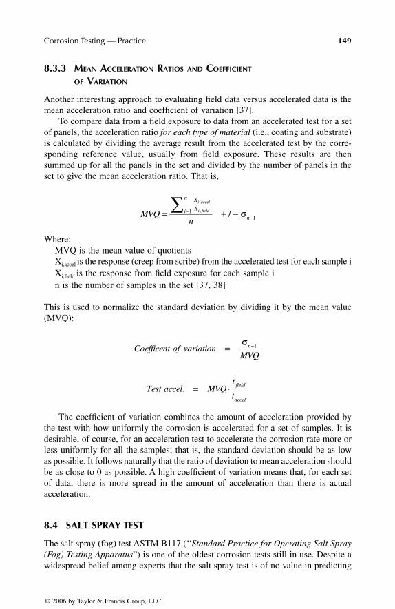
Corrosion Testing — Practice 149
8.3.3 MEAN ACCELERATION RATIOS AND COEFFICIENT
OF VARIATION
Another interesting approach to evaluating field data versus accelerated data is themean acceleration ratio and coefficient of variation [37].
To compare data from a field exposure to data from an accelerated test for a setof panels, the acceleration ratio for each type of material (i.e., coating and substrate)is calculated by dividing the average result from the accelerated test by the corre-sponding reference value, usually from field exposure. These results are thensummed up for all the panels in the set and divided by the number of panels in theset to give the mean acceleration ratio. That is,
Where:MVQ is the mean value of quotientsXi,accel is the response (creep from scribe) from the accelerated test for each sample iXi,field is the response from field exposure for each sample in is the number of samples in the set [37, 38]
This is used to normalize the standard deviation by dividing it by the mean value(MVQ):
The coefficient of variation combines the amount of acceleration provided bythe test with how uniformly the corrosion is accelerated for a set of samples. It isdesirable, of course, for an acceleration test to accelerate the corrosion rate more orless uniformly for all the samples; that is, the standard deviation should be as lowas possible. It follows naturally that the ratio of deviation to mean acceleration shouldbe as close to 0 as possible. A high coefficient of variation means that, for each setof data, there is more spread in the amount of acceleration than there is actualacceleration.
8.4 SALT SPRAY TEST
The salt spray (fog) test ASTM B117 (‘‘Standard Practice for Operating Salt Spray(Fog) Testing Apparatus”) is one of the oldest corrosion tests still in use. Despite awidespread belief among experts that the salt spray test is of no value in predicting
MVQn
X
Xi
n
n
i accel
i field= + −=−
∑ ,
, /11σ
Coefficent ofMVQ
nvariation = −σ 1
Test accel MVQt
tfield
accel
. = ⋅
7278_C008.fm Page 149 Friday, February 3, 2006 3:01 PM
© 2006 by Taylor & Francis Group, LLC

150 Corrosion Control Through Organic Coatings
performance, or even relative ranking, of coatings in most applications, it is the mostfrequently specified test for evaluating paints and substrates.
8.4.1 THE REPUTATION OF THE SALT SPRAY TEST
The salt spray test has such a poor reputation among workers in the field that theword ‘‘infamous” is sometimes used as a prefix to the test number. In fact, nearlyevery peer-reviewed paper published these days on the subject of accelerated testingstarts with a condemnation of the salt spray test [39-44]. For example:
• ‘‘In fact, it has been recognized for many years that when ranking theperformance levels of organic coating systems, there is little if any cor-relation between results from standard salt spray tests and practical expe-rience.” [3]
• ‘‘The well-known ASTM B117 salt spray test provides a comparison ofcold-rolled and electrogalvanized steel within several hundred hours.Unfortunately, the salt spray test is unable to predict the well-knownsuperior corrosion resistance of galvanized relative to uncoated cold rolledsteel sheet.” [45]
• ‘‘Salt spray provides rapid degradation but has shown poor correlationwith outdoor exposures; it often produces degradation by mechanismsdifferent from those seen outdoors and has relatively poor precision.” [46]
Many studies comparing salt spray results and actual field exposure have beenperformed. Coating types, substrates, locations, and length of time have been varied.No correlations have been found to exist between the salt spray and the followingservice environments:
• Galveston Island, Texas (16 months), 800 meters from the sea [47]• Sea Isle City, New Jersey (28 months), a marine exposure site [48]• Daytona Beach, Florida (3 years) [49]• Pulp mills at Lessebo and Skutskar, Sweden, painted hot-rolled steel
substrates (4 years) [50] and painted aluminium, galvanized steel andcarbon steel substrates (5 years) [51]
• Kure Beach, North Carolina, a marine exposure site [52-54]
8.4.2 SPECIFIC PROBLEMS WITH THE SALT SPRAY TEST
Appleman and Campbell [55] have examined each of the accelerating stresses inthe salt spray test and its effect on the corrosion mechanism compared to outdooror ‘‘real-life’’ exposure. They found the following flaws in the salt spray test:
a. Constant humid surface• Neither the paint nor the substrate experience wet /dry cycles. Corro-
sion mechanisms may not match those seen in the field; for example,in zinc-rich coatings or galvanized substrates, the zinc is not likely toform a passive film as it does in the field.
7278_C008.fm Page 150 Friday, February 3, 2006 3:01 PM
© 2006 by Taylor & Francis Group, LLC

Corrosion Testing — Practice 151
• Water uptake and hydrolysis are greater than in the field.• A constant water film with high conductivity is present, which does
not happen in the field.
b. Elevated temperature• Water, oxygen, and ion transport are greater than in the field.• For some paints, the elevated temperature of the test comes close to
the glass transition temperature of the binder.
c. High chloride concentration (effect on corrosion depends on the typeof protection the coating offers)
• For sacrificial coatings, such as zinc-rich primers, the high chloridecontent together with the constant high humidity means that the zincis not likely to form a passive film as it does in the field.
• For inhibitive coatings, chlorides adsorb on the metal surface, wherethey prevent passivation.
• For barrier coatings, the osmotic forces are much less than in the field;in fact, they may be reversed completely from that which is seen inreality. In the salt spray test, corrosion at a scribe or defect is exagger-atedly aggressive compared with a scribe under intact paint.
Lyon, Thompson, and Johnson [56] point out that the high sodium chloride contentof the salt spray test can result in corrosion morphologies and behaviors that are notrepresentative of natural conditions. Harrison has pointed out that the test is inappro-priate for use on zinc — galvanized substrates or primers with zinc phosphate pigments,for example — because, in the constant wetness of the salt spray test, zinc undergoesa corrosion mechanism that it would not undergo in real service [57]. This is a well-known and well-documented phenomenon and is discussed in depth in chapter 7.
8.4.3 IMPORTANCE OF WET/DRY CYCLING
Skerry, Alavi, and Lindgren have identified three factors of importance in the deg-radation and corrosion of painted steel that are not modeled by the salt spray test:wet/dry cycling, a suitable choice of electrolyte, and the effects of UV radiation(critical because of the breakdown of polymer bonds in the paint) [3].
Lyon, Thompson, and Johnson explain why wet/dry cycles are an importantfactor in an accelerated test method [56]:
Many studies have shown the specific importance of wetting and drying on atmosphericcorrosion... On a dry metal surface, as the relative humidity (RH) is increased, thecorrosion rate initially rises, then decreases to a relatively constant value which becomesgreater as the RH is increased. A similar effect is observed during physical wettingand drying of a surface. Thus, on initial wetting, the corrosion rate rises rapidly asaccumulated surface salts first dissolve. The rate then decreases as the surface electro-lyte dilutes with continued wetting. The corrosion rate also rises significantly duringdrying because of both the increasing ionic activity as the surface electrolyte concentrates
7278_C008.fm Page 151 Friday, February 3, 2006 3:01 PM
© 2006 by Taylor & Francis Group, LLC

152 Corrosion Control Through Organic Coatings
and the reduced diffusion layer thickness for oxygen as the condensed phase becomethinner. However, eventually, when the ionic strength of the electrolyte layer becomesvery high and salts begin to crystallize, the corrosion rate decreases.
Simpson, Ray, and Skerry agree that ‘‘cyclic wetting and drying of electrolyte layersfrom the panel surface is thought to stress the coating in a more realistic mannerthan, for example, a continuous ASTM B-117 salt spray test, where panels are placedin a constant, high relative humidity (RH) environment” [58]. Several workers inthis field have reported that cyclic testing with a significant amount of drying timeyields more realistic results on zinc-coated substrates [59-61].
REFERENCES
1. Goldie, B., Prot. Coat. Eur., 1, 23, 1996.2. Appelman, B., J. Coat. Technol., 62, 57, 1990.3. Skerry, B.S., Alavi, A., and Lindgren, K.I. J. Coat. Technol., 60, 97, 1988.4. Townsend, H., Development of an improved laboratory corrosion test by the auto-
motive and steel industries, in Proc. 4th Annual ESD Advanced Coatings Conference,Dearborn, MI, 8-10 November 1994. Engineering Society of Detroit (ESD), 1994.
5. Prfung des korrosionsschutzes von kraftfahrzeuglackierungen bei zyklisch wech-selnder beanspruchung, Std. VDA 621-415, German Association of the AutomotiveIndustry, Frankfurt, Germany.
6. Accelerated corrosion test, Corporate Standard STD 423-0014, Issue 1, Volvo Group,Gothenburg, 2003.
7. Ström, M., in Proc. Conf. Automotive Corrosion and Prevention. Dearborn, MI, Dec4-6, 1989, Society of Automotive Engineers, Warrendale, PA, 1989.
8. Ström, M. and Ström, G., Proc. Skan Zink ’91, Helsingör (Sweden), Sept. 1991.9. Pletcher, D., A First Course in Electrode Processes, The Electrochemical Consultancy
Ltd., Romsey, England, 1991, 229.10. ISO 4628/3-1982-Designation of degree of rusting, International Organization for
Standardization, Geneva, 1982.11. Paul, S., (Ed.), Surface Coatings: Science & Technology, 2nd ed., John Wiley & Sons,
Chichester, England. 1996.12. Sacco, E.A. et al., Lat. Am. Appl. Res. 32, 4, 2002.13. Walker, P., Paint Technol., 31, 22. 1967.14. Özcan, M., Dehri, I. and Erbil, M., Prog. Org. Coat., 44, 279, 2002.15. Lavaert, V. et al., Prog. Org. Coat., 38, 213, 2000.16. Krolikowska, A., Prog. Org. Coat., 39, 37, 2000.17. Sekine, I., Proc. 99th Symposium on Corrosion Protection, Tokyo, Japan, 1994, 51.18. Sekine, I. and Yuasa, M., Proc. Annual Meeting of the Japan Society of Colour
Material, Tokyo, 1995, 70.19. Sekine, I., Prog. Org. Coat., 31, 73, 1997.20. Kendig, M. and Scully, J. Corrosion, 46, 22, 1990.21. Walter, G.W., Corros. Sci., 32, 1041, 1991.22. Walter, G.W., Corros. Sci.,32, 1059, 1991.23. Walter, G.W., Corros. Sci.,32, 1085, 1991.24. M. Stratmann et al., Corros. Sci.,6, 715, 1990.25. Forsgren, A. and Thierry, D., Corrosion properties of coil-coated galvanized steel,
using field exposure and advanced electrochemical techniques, SCI Rapport 2001:4E.Swedish Corrosion Institute (SCI), Stockholm, 2001.
7278_C008.fm Page 152 Friday, February 3, 2006 3:01 PM
© 2006 by Taylor & Francis Group, LLC

Corrosion Testing — Practice
153
26. Bard, A.J. and Faulkner, L.R.,
Electrochemical Methods
, John Wiley & Sons, NewYork, 1980, chap. 6.
27. Glicinski, A.G. and Hegedus, C.R.,
Prog. Org. Coat.
, 32, 81, 1997.28. Joanicot, M., Granier, V. and Wong, K.,
Prog. Org. Coat.
, 32, 109, 1997.29. Gerharz, B., et al.,
Prog. Org. Coat.
, 32, 75, 1997.30. Tzitzinou, A. et al.,
Prog. Org. Coat.
, 35, 89, 1999.31. Forsgren, A. and Persson, D., Changes in the Surface Energy of Steel Caused by
Acrylic Waterborne Paints Prior to Cure, SCI Rapport 2000:5E. Swedish CorrosionInstitute (SCI), Stockholm, 2000.
32. Almeida, E., Balmayore, M. and Santos, T.,
Prog. Org. Coat.
, 44, 233, 2002.33. Shaw, D.,
Introduction to Colloid and Surface Chemistry
, 4th ed., Butterworth-Heinemann Ltd., 1991, chapters 3 and 5.
34. Kim, K.S, Winograd, N. and Davis, R.E.,
J. Amer. Chem. Soc.
, 93, 6296, 1971.35. Skerry, B.S. and Eden, D.A.,
Prog. Org. Coat.
, 15, 269, 1987.36. Chen, C.T. and Skerry, B.S.,
Corrosion
, 47, 598, 1991.37. Ström, M. and Ström. G.,
SAE Technical Paper Series, 932338
. Society of AutomotiveEngineers, Warrendale, PA,
1993.38. Ström, M., Utviklingen av metallbelegg i bilindustrin: Status, trender og Volvos
erfaringer, in
Proc Overflatedager ’92,
Trondheim, 1992. (in Norwegian)39. LaQue, F.L.,
Marine Corrosion
, Wiley, New York, 1975.40. Lambert, M.R., et al.,
Ind. Eng. Chem. Prod. Res. Dev
., 24, 378, 1985.41. Lyon, S.B. et al.,
Corrosion
, 43, 12, 1987. 42. Timmins, F.D.,
J. Oil Color Chem. Assn
., 62, 131, 1979.43. Funke, W.,
J. Oil Color Chem. Assn
., 62, 63, 1979.44. Skerry, B.S. and Simpson, C.H.,
Corrosion
, 49, 663, 1993.45. Townsend, H.E., Development of an improved laboratory corrosion test by the
automotive and steel industries, in
Proc. 4th Annual ESD Advanced Coating Con-ference
, Dearborn, MI, 8-10 November 1994. Engineering Society of Detroit (ESD),1994.
46. Appleman, B.,
J. Prot. Coat. Linings
, 6, 71, 1989.47. Struemph, D.J. and Hilko, J.,
IEEE Trans. on Power Delivery
, PWRD-2, 823,1987.
48. Chong, S.L., Comparison of laboratory testing method for bridge coatings, in
Proc.4th World Congress on Coating Systems for Bridge and Steel Structures Bridging theEnvironment
, St. Louis, MO, 1995.49. Rommal, H.E.G. et al., Accelerated test development for coil-coated steel building
panels, in
Proc. Corrosion ’98
, San Diego, CA, National Association of CorrosionEngineers (NACE), 1998, Paper 356.
50. Forsgren, A. and Palmgren, S.,
Salt spray test vs. field results for coated samples: part I,
SCI Rapport 1998:4E, Swedish Corrosion Institute (SCI), Stockholm, 1998.51. Forsgren, A., Rendahl, B. and Appelgren, C.,
Salt spray test vs. field results for coatedsamples: part II,
SCI Rapport 1998:6E, Swedish Corrosion Institute (SCI), Stockholm,1998.
52. Appleman, B.R., Bruno, J.A., and Weaver, R.E.F.,
Performance of Alternate Coatingsin the Environment (PACE) Volume I: Ten Year Field Data
, FHWA-RD-89-127, U.S.Federal Highway Administration, Washington D.C., 1989.
53. Appleman, B.R., Weaver, R.E.F. and Bruno, J.A.,
Performance of Alternate Coatingsin the Environment (PACE) Volume II: Five Year Field Data and Bridge Data ofImproved Formulations
, FHWA-RD-89-235, U.S. Federal Highway Administration,Washington D.C., 1989.
7278_C008.fm Page 153 Wednesday, March 1, 2006 12:43 PM
© 2006 by Taylor & Francis Group, LLC
154
Corrosion Control Through Organic Coatings
54. Appleman, B.R., Weaver, R.E.F. and Bruno, J.A.,
Performance of Alternate Coatingsin the Environment (PACE) Volume III: Executive Summary
, FHWA-RD-89-236, U.S.Federal Highway Administration, Washington D.C., 1989.
55. Appleman, B.R. and Campbell, P.G.,
J. Coat. Technol.
, 54, 17, 1982.56. Lyon, S.B., Thompson, G.E. and Johnson, J.B., Materials evaluation using wet-dry
mixed salt spray tests, in
New Methods for Corrosion Testing of Aluminum Alloys
,ASTM STP 1134, V.S. Agarwala and G.M. Ugiansky, Eds., American Society forTesting and Materials, Philadelphia, PA, 1992, 20.
57. Harrison, J.B. and Tickle, T.C.,
J. Oil Color Chem. Assn
., 45, 571, 1962.58. Simpson, C.H, Ray, C.J. and Skerry, B.S.,
J. Prot. Coat. Linings
, 8, 28, 1991.59. Smith, D.M. and Whelan, G.W.,
SAE Technical Paper Series, 870646
, Society ofAutomotive Engineers, Warrendale, PA, 1987.
60. Nowak, E.T., Franks, L.L. and Froman, G.W.,
SAE Technical Paper Series, 820427
,Society of Automotive Engineers, Warrendale, PA, 1982.
61. Standish, J.V., Whelan, G.W. and Roberts, T.R.,
SAE Technical Paper Series, 831810
.Society of Automotive Engineers, Warrendale, PA, 1983.
7278_C008.fm Page 154 Wednesday, March 1, 2006 12:43 PM
© 2006 by Taylor & Francis Group, LLC