Embed Size (px)
Citation preview
Cornell UniversityCornell MineSweeper
Vehicle Design Report
Steven Liu, Gil Lee, Katie Lee Meusling, Hamzah Sikander,
Clauda Ephrem, Platon Dickey, Kevin Ullman, Jeff Slosberg, Greg Meese
Faculty Advisor StatementI certify that the engineering design of the robot Nero, described in this report has been significant and equivalent to what might be awarded credit in a senior design course.
E.G.______________________________
Professor Ephrahim GarciaDepartment of Mechanical and Aerospace Engineering, Cornell University
Table of Contents
1 Introduction 2
2 Design Process 2
2.1 Design Objective & Requirements Development 3
3 Hardware 4
3.1 Innovations 5
3.2 Software and Hardware Processing 5
3.3 Chassis 5
3.4 Drive Train and Controls 6
3.4.1 Overview 6
3.4.2 Motor and Gearing Selection 6
3.4.3 Results and Testing 7
3.5 Power and Quality Control 8
3.6 Electronics Protection and Safety 8
3.6.1 Electronics Protection 8
3.6.2 Wireless E-stop 9
4 Software 9
4.1 General Framework 9
4.1.1 Platform 9
4.1.2 Structure 10
4.1.3 Modularity of Code and Hardware 10
4.2 Software Innovation 10
4.3 Data Acquisition and Preprocessing 11
4.3.1 Camera Processor 11
4.3.2 Lane Following 12
4.3.3 LIDAR Processing 12
4.4 Artificial Intelligence 13
4.4.1 Navigation Algorithm 13
2
4.4.2 Autonomous Strategy 14
4.4.3 Speed Control 15
5 Conclusion 15
3
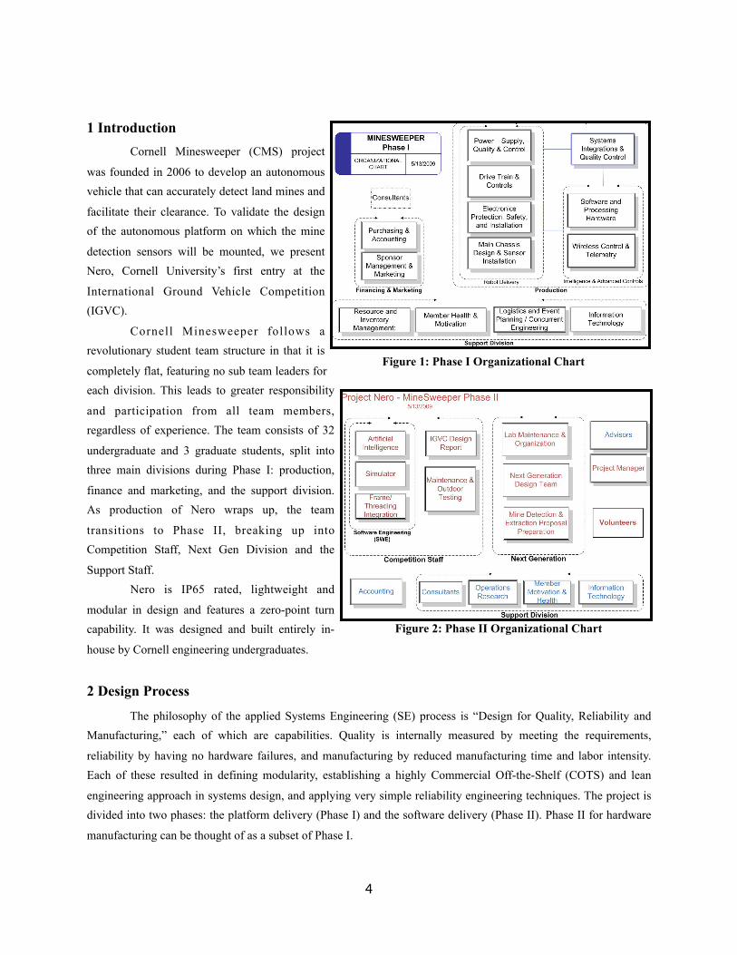
1 Introduction Cornell Minesweeper (CMS) project
was founded in 2006 to develop an autonomous vehicle that can accurately detect land mines and
facilitate their clearance. To validate the design of the autonomous platform on which the mine
detection sensors will be mounted, we present Nero, Cornell University’s first entry at the
International Ground Vehicle Competition (IGVC).
Cornell Minesweeper follows a revolutionary student team structure in that it is
completely flat, featuring no sub team leaders for each division. This leads to greater responsibility
and participation from all team members, regardless of experience. The team consists of 32
undergraduate and 3 graduate students, split into three main divisions during Phase I: production,
finance and marketing, and the support division. As production of Nero wraps up, the team
transitions to Phase II, breaking up into Competition Staff, Next Gen Division and the
Support Staff. Nero is IP65 rated, lightweight and
modular in design and features a zero-point turn capability. It was designed and built entirely in-
house by Cornell engineering undergraduates.
2 Design Process
The philosophy of the applied Systems Engineering (SE) process is “Design for Quality, Reliability and Manufacturing,” each of which are capabilities. Quality is internally measured by meeting the requirements,
reliability by having no hardware failures, and manufacturing by reduced manufacturing time and labor intensity. Each of these resulted in defining modularity, establishing a highly Commercial Off-the-Shelf (COTS) and lean
engineering approach in systems design, and applying very simple reliability engineering techniques. The project is divided into two phases: the platform delivery (Phase I) and the software delivery (Phase II). Phase II for hardware
manufacturing can be thought of as a subset of Phase I.
4
Figure 1: Phase I Organizational Chart
Figure 2: Phase II Organizational Chart
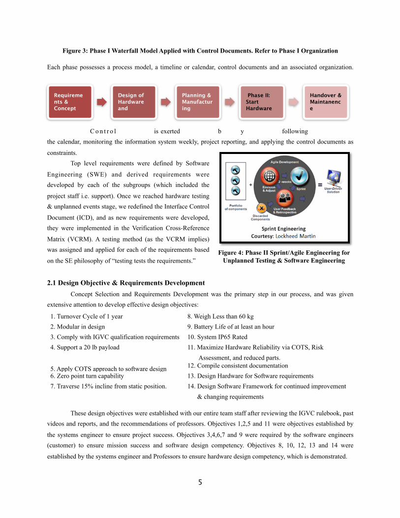
Figure 3: Phase I Waterfall Model Applied with Control Documents. Refer to Phase I Organization
Each phase possesses a process model, a timeline or calendar, control documents and an associated organization.
C o n t r o l is exerted b y following the calendar, monitoring the information system weekly, project reporting, and applying the control documents as
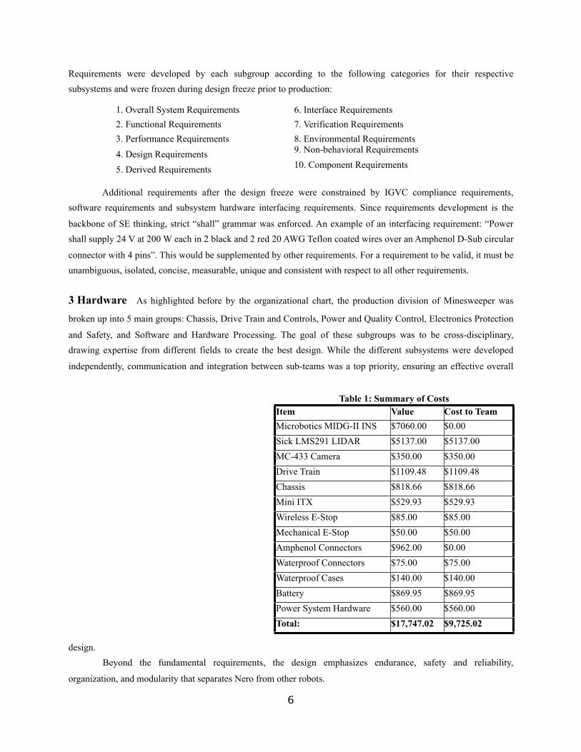
constraints. Top level requirements were defined by Software
Engineering (SWE) and derived requirements were developed by each of the subgroups (which included the
project staff i.e. support). Once we reached hardware testing & unplanned events stage, we redefined the Interface Control
Document (ICD), and as new requirements were developed, they were implemented in the Verification Cross-Reference
Matrix (VCRM). A testing method (as the VCRM implies) was assigned and applied for each of the requirements based
on the SE philosophy of “testing tests the requirements.”
2.1 Design Objective & Requirements Development Concept Selection and Requirements Development was the primary step in our process, and was given extensive attention to develop effective design objectives:
1. Turnover Cycle of 1 year 8. Weigh Less than 60 kg2. Modular in design 9. Battery Life of at least an hour3. Comply with IGVC qualification requirements 10. System IP65 Rated4. Support a 20 lb payload 11. Maximize Hardware Reliability via COTS, Risk
Assessment, and reduced parts.
5. Apply COTS approach to software design 12. Compile consistent documentation6. Zero point turn capability 13. Design Hardware for Software requirements7. Traverse 15% incline from static position. 14. Design Software Framework for continued improvement
& changing requirements
These design objectives were established with our entire team staff after reviewing the IGVC rulebook, past videos and reports, and the recommendations of professors. Objectives 1,2,5 and 11 were objectives established by
the systems engineer to ensure project success. Objectives 3,4,6,7 and 9 were required by the software engineers (customer) to ensure mission success and software design competency. Objectives 8, 10, 12, 13 and 14 were
established by the systems engineer and Professors to ensure hardware design competency, which is demonstrated.
5
Figure 4: Phase II Sprint/Agile Engineering for Unplanned Testing & Software Engineering
Requirements & Concept
Design of Hardware and
Planning & Manufacturing
Phase II: Start Hardware
Handover & Maintanence
Requirements were developed by each subgroup according to the following categories for their respective subsystems and were frozen during design freeze prior to production:
1. Overall System Requirements 6. Interface Requirements2. Functional Requirements 7. Verification Requirements3. Performance Requirements 8. Environmental Requirements4. Design Requirements 9. Non-behavioral Requirements
5. Derived Requirements 10. Component Requirements
Additional requirements after the design freeze were constrained by IGVC compliance requirements, software requirements and subsystem hardware interfacing requirements. Since requirements development is the
backbone of SE thinking, strict “shall” grammar was enforced. An example of an interfacing requirement: “Power shall supply 24 V at 200 W each in 2 black and 2 red 20 AWG Teflon coated wires over an Amphenol D-Sub circular
connector with 4 pins”. This would be supplemented by other requirements. For a requirement to be valid, it must be unambiguous, isolated, concise, measurable, unique and consistent with respect to all other requirements.
3 Hardware As highlighted before by the organizational chart, the production division of Minesweeper was
broken up into 5 main groups: Chassis, Drive Train and Controls, Power and Quality Control, Electronics Protection
and Safety, and Software and Hardware Processing. The goal of these subgroups was to be cross-disciplinary, drawing expertise from different fields to create the best design. While the different subsystems were developed
independently, communication and integration between sub-teams was a top priority, ensuring an effective overall
design. Beyond the fundamental requirements, the design emphasizes endurance, safety and reliability,
organization, and modularity that separates Nero from other robots.
6
Table 1: Summary of CostsTable 1: Summary of CostsTable 1: Summary of CostsItem Value Cost to TeamMicrobotics MIDG-II INS $7060.00 $0.00Sick LMS291 LIDAR $5137.00 $5137.00MC-433 Camera $350.00 $350.00Drive Train $1109.48 $1109.48Chassis $818.66 $818.66Mini ITX $529.93 $529.93Wireless E-Stop $85.00 $85.00Mechanical E-Stop $50.00 $50.00Amphenol Connectors $962.00 $0.00Waterproof Connectors $75.00 $75.00Waterproof Cases $140.00 $140.00Battery $869.95 $869.95Power System Hardware $560.00 $560.00Total: $17,747.02 $9,725.02
Throughout the design process, extensive use of the SolidWorks™ Computer Aided Drafting and Design tool was utilized in product visualization and troubleshooting. Every component from design to fabrication was
drafted: aiding in fabrication, assembly and redesign every step of the way.
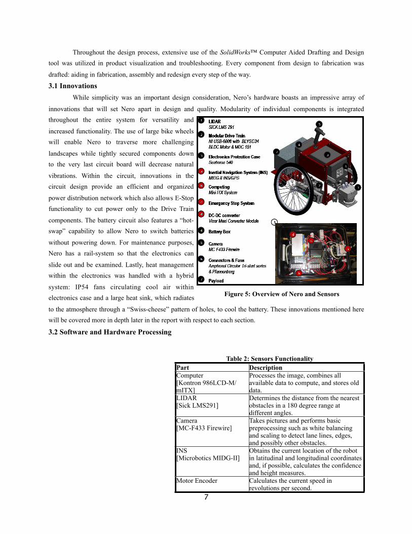
3.1 Innovations While simplicity was an important design consideration, Nero’s hardware boasts an impressive array of
innovations that will set Nero apart in design and quality. Modularity of individual components is integrated throughout the entire system for versatility and
increased functionality. The use of large bike wheels will enable Nero to traverse more challenging
landscapes while tightly secured components down to the very last circuit board will decrease natural
vibrations. Within the circuit, innovations in the circuit design provide an efficient and organized
power distribution network which also allows E-Stop functionality to cut power only to the Drive Train
components. The battery circuit also features a “hot-swap” capability to allow Nero to switch batteries
without powering down. For maintenance purposes, Nero has a rail-system so that the electronics can
slide out and be examined. Lastly, heat management within the electronics was handled with a hybrid
system: IP54 fans circulating cool air within electronics case and a large heat sink, which radiates
to the atmosphere through a “Swiss-cheese” pattern of holes, to cool the battery. These innovations mentioned here will be covered more in depth later in the report with respect to each section.
3.2 Software and Hardware Processing
7
Table 2: Sensors FunctionalityTable 2: Sensors FunctionalityPart DescriptionComputer [Kontron 986LCD-M/mITX]
Processes the image, combines all available data to compute, and stores old data.
LIDAR [Sick LMS291]
Determines the distance from the nearest obstacles in a 180 degree range at different angles.
Camera [MC-F433 Firewire]
Takes pictures and performs basic preprocessing such as white balancing and scaling to detect lane lines, edges, and possibly other obstacles.
INS [Microbotics MIDG-II]
Obtains the current location of the robot in latitudinal and longitudinal coordinates and, if possible, calculates the confidence and height measures.
Motor Encoder Calculates the current speed in revolutions per second.
Figure 5: Overview of Nero and Sensors
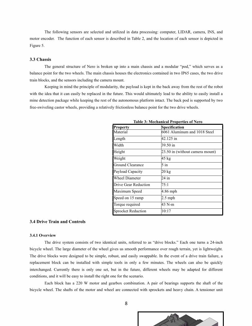
The following sensors are selected and utilized in data processing: computer, LIDAR, camera, INS, and motor encoder. The function of each sensor is described in Table 2, and the location of each sensor is depicted in
Figure 5.
3.3 Chassis The general structure of Nero is broken up into a main chassis and a modular “pod,” which serves as a balance point for the two wheels. The main chassis houses the electronics contained in two IP65 cases, the two drive
train blocks, and the sensors including the camera mount. Keeping in mind the principle of modularity, the payload is kept in the back away from the rest of the robot
with the idea that it can easily be replaced in the future. This would ultimately lead to the ability to easily install a mine detection package while keeping the rest of the autonomous platform intact. The back pod is supported by two
free-swiveling castor wheels, providing a relatively frictionless balance point for the two drive wheels.
3.4 Drive Train and Controls
3.4.1 Overview
The drive system consists of two identical units, referred to as “drive blocks.” Each one turns a 24-inch bicycle wheel. The large diameter of the wheel gives us smooth performance over rough terrain, yet is lightweight.
The drive blocks were designed to be simple, robust, and easily swappable. In the event of a drive train failure, a replacement block can be installed with simple tools in only a few minutes. The wheels can also be quickly
interchanged. Currently there is only one set, but in the future, different wheels may be adapted for different conditions, and it will be easy to install the right one for the scenario.
Each block has a 220 W motor and gearbox combination. A pair of bearings supports the shaft of the bicycle wheel. The shafts of the motor and wheel are connected with sprockets and heavy chain. A tensioner unit
8
Table 3: Mechanical Properties of NeroTable 3: Mechanical Properties of NeroProperty SpecificationMaterial 6061 Aluminum and 1018 SteelLength 42.125 inWidth 39.50 inHeight 23.50 in (without camera mount)Weight 45 kgGround Clearance 5 inPayload Capacity 20 kgWheel Diameter 24 inDrive Gear Reduction 75:1Maximum Speed 4.86 mphSpeed on 15 ramp 2.5 mphTorque required 43 N-mSprocket Reduction 10:17
keeps the chain tight, and provides some shock absorption to protect the motor from abrupt loading. The motor driver and USB interface are housed in a waterproof case; there are connection points for power and for signal from
the main computer.
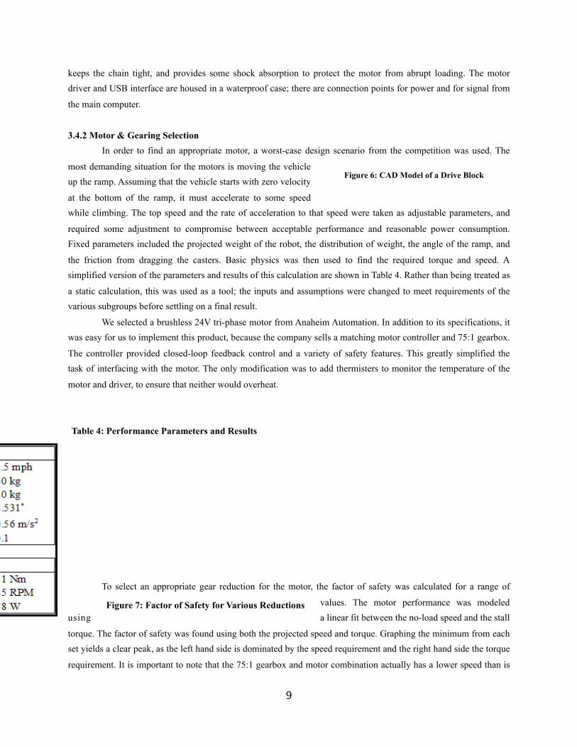
3.4.2 Motor & Gearing Selection In order to find an appropriate motor, a worst-case design scenario from the competition was used. The
most demanding situation for the motors is moving the vehicle up the ramp. Assuming that the vehicle starts with zero velocity
at the bottom of the ramp, it must accelerate to some speed while climbing. The top speed and the rate of acceleration to that speed were taken as adjustable parameters, and
required some adjustment to compromise between acceptable performance and reasonable power consumption. Fixed parameters included the projected weight of the robot, the distribution of weight, the angle of the ramp, and
the friction from dragging the casters. Basic physics was then used to find the required torque and speed. A simplified version of the parameters and results of this calculation are shown in Table 4. Rather than being treated as
a static calculation, this was used as a tool; the inputs and assumptions were changed to meet requirements of the various subgroups before settling on a final result.
We selected a brushless 24V tri-phase motor from Anaheim Automation. In addition to its specifications, it was easy for us to implement this product, because the company sells a matching motor controller and 75:1 gearbox.
The controller provided closed-loop feedback control and a variety of safety features. This greatly simplified the task of interfacing with the motor. The only modification was to add thermisters to monitor the temperature of the
motor and driver, to ensure that neither would overheat.
To select an appropriate gear reduction for the motor, the factor of safety was calculated for a range of
values. The motor performance was modeled using a linear fit between the no-load speed and the stall
torque. The factor of safety was found using both the projected speed and torque. Graphing the minimum from each set yields a clear peak, as the left hand side is dominated by the speed requirement and the right hand side the torque
requirement. It is important to note that the 75:1 gearbox and motor combination actually has a lower speed than is
9
Figure 6: CAD Model of a Drive Block
Table 4: Performance Parameters and Results
Figure 7: Factor of Safety for Various Reductions
necessary for our application. The gear reduction in this case refers to increasing the speed by decreasing the torque. From the graph, we picked a gear reduction of 10:17. This gives a factor of safety of 2.16 in regards to torque, and
gives a theoretical maximum speed on flat ground of 4.86 mph, just under the speed limit of the competition.
3.4.3 Results and Testing Testing the drive blocks on the vehicle was successful. The platform achieves speeds of approximately 5
mph on flat ground, as predicted. Although we were unable to find a ramp of the exact angle specified, Nero is capable of climbing grassy slopes of a much steeper angle than that required for the competition. The motor
controller also performs well. Performing a zero-point turn gives only negligible drift of the robot center, showing that the motor controllers responsible for setting the speeds performs as expected.
3.5 Power and Quality Control To provide for a total power consumption of 310W at a peak of 30A
with a factor of safety of 2 (Table 5), a high power supply system that could
handle high power and amperage was required. As a result, with a minimum run-cycle of 30 minutes and up to 10 cycles expected per day, 51.8V, 518Wh
polymer Li-Ion rechargeable batteries were selected for their high power source and peak current tolerance of 40 Amps. Nominal 48V systems are
common in professional applications in the industry and are the military-specification norm.
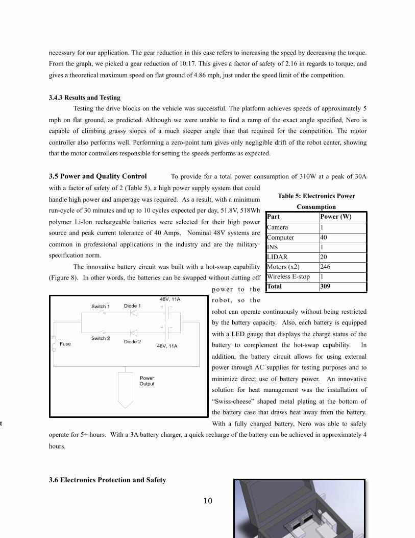
The innovative battery circuit was built with a hot-swap capability (Figure 8). In other words, the batteries can be swapped without cutting off
p o w e r t o t h e robo t , so t he
robot can operate continuously without being restricted by the battery capacity. Also, each battery is equipped
with a LED gauge that displays the charge status of the battery to complement the hot-swap capability. In
addition, the battery circuit allows for using external power through AC supplies for testing purposes and to
minimize direct use of battery power. An innovative solution for heat management was the installation of
“Swiss-cheese” shaped metal plating at the bottom of the battery case that draws heat away from the battery.
With a fully charged battery, Nero was able to safely operate for 5+ hours. With a 3A battery charger, a quick recharge of the battery can be achieved in approximately 4
hours.
3.6 Electronics Protection and Safety
10
Table 5: Electronics Power Consumption
Table 5: Electronics Power Consumption
Part Power (W)Camera 1Computer 40INS 1LIDAR 20Motors (x2) 246Wireless E-stop 1Total 309
Figure 8: Hot-Swap Circuit
The primary design concern was to satisfy the following requirements: ensuring physical and electrical protection of the electronics and implementing a hardware-based wireless emergency-stop solution with an effective
range of at least 50 feet that brings the robot to a quick and complete stop.
3.6.1 Electronics Protection The electronics require proper protection to guarantee maximum performance and prevent any potential
damage. Physically, the main electronics are securely mounted inside the electronics case and the battery case, both of which are
IP54 rated waterproof and dustproof. Further, all connectors utilized for the connections through the electronics case and the battery case are IP65 rated waterproof. Electrically, heat management was the main design concern.
The heat sink on the computer is responsible for managing heat dissipation of the computer, while the IP54 rated fans circulate air from one end of the electronics case to the other. Also, in the electronics case, direct contact
between the floor of the case and the electronics is avoided. This is accomplished by raising the acrylic boards on which the electronic components are mounted to prevent concentrated heat flow. The innovative two-level stacking
of electronic components in the electronics case is derived from the same principle as well as efficiently using the space within the electronics case. To prevent the effects of unexpected surge current, a circuit breaker is installed in
the battery case, as well as diodes that are configured to handle 20-50 A of current. Heat dissipation was not a problem during the entirety of Nero’s testing phase.
In order to facilitate the maintenance of the electronics case, simple rail system was incorporated onto the electronic case so that it can be slid out and opened for examination. Throughout the system, United States
Military Standard (mil-spec) wires are used to ensure safety and reliability. Efficient wire management was given particular attention as it enhanced organization and simplicity of the wiring scheme, avoided potential voltage drops
due to long wire connections, and allowed for convenient maintenance. Also, the use of Amphenol connectors, Eurostrip, and Molex connectors permit not only safe and secure connections, but also modularity, enabling a
convenient and easy replacement of components and transportation. Eurostrip, in particular, enables parallel distribution of power so that the electronic components can be connected without affecting the rest of the system.
3.6.2 Wireless E-stop
For the wireless e-stop solution, we purchased a COTS RF receiver with a guaranteed reception range of 100 feet and a RF transmitter with a set/reset toggle functionality. The purchased module was incorporated in series
with the mechanical e-stop circuit to cut off power to the motors exclusively, bringing Nero to quick and complete stop while leaving other electronics functional. The set/reset capability and the guaranteed range of over 100 feet
with line of sight were tested and confirmed. At full speed, Nero completely stops within 3 seconds and 6 feet.
4 Software
4.1 General Framework
11
Figure 9: CAD Model of Electronics Case
4.1.1 Platform Nero runs on an Ubuntu Linux platform. The primary consideration in the decision was that many of the
libraries utilized are only supported by Linux. In addition, Ubuntu is open source, well-documented, familiar to the team, and has less overhead than Windows. Programs are written in C++ using the Eclipse Integrated Development
Environment (IDE). C++ runs faster than Java but still has the benefits of modularity associated with the object-oriented design.
4.1.2 Structure The core of the data processing is the Data
Processor class whose main objective is to delegate work to the other processors, namely the LIDAR, camera, INS,
and motors and combine the data received from these processors. Processed data is passed to the AI, which
calculates routes and passes commands to the Motor Encoder which communicates with the motors to adjust
Nero’s speed and direction.
4.1.3 Modularity of Code and Hardware Our code is designed such that the components are
modular and they can be easily swapped or replaced. One example of this modularity is that the code related to each
Input/Output (I/O) device is limited to a single class or package. For example, if the camera were replaced with 2
new cameras, the main structure of the code could be left unchanged as long as the new class that replaces the
current camera processor used the correct interface. Thus, the sensors are quite modular and easily swapped out.
Similarly, we currently have two AI strategies, Navigation and Autonomous; however, we are in no way limited to these strategies. Again we have an interface for an AI strategy, and any number of strategies can be
interchanged with minimal effort.
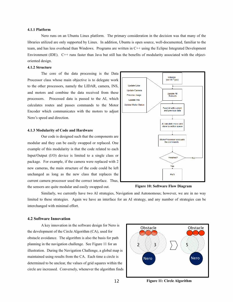
4.2 Software Innovation A key innovation in the software design for Nero is the development of the Circle Algorithm (CA), used for
obstacle avoidance. The algorithm is also the basis for path planning in the navigation challenge. See Figure 11 for an
illustration. During the Navigation Challenge, a global map is maintained using results from the CA. Each time a circle is
determined to be unclear, the values of grid squares within the circle are increased. Conversely, whenever the algorithm finds
12
Figure 10: Software Flow Diagram
Nero
Obstacle
2 3
Nero
5
Obstacle
Figure 11: Circle Algorithm
a clear circle, the values of the grid squares are decreased.
Circle Algorithm:circle = circle directly in front of robot, with size MAXSIZEcircle_count = 1, turn_count = 0, turn_direction = leftwhile (circle is not clear && circle size > MINSIZE) do /* the circle is unclear so mark the map accordingly */ update map information if (turn_count = num_turns_by_circle_count (circle_count)) then /* num_turns_by_circle count is a function that determines how many times the circle should be shifted before becoming smaller. The circle sweeps across a greater angle as it decreases in size */ circle = circle_size * SCALING_FACTOR circle_count++ else /* circle is swept from 0 degrees (directly in front of the robot) left or right */ circle = rotate_circle (circle, turn_multiplier * TURN_ANGLE, turn_direction) /* turn multiplier increases the angle which the circle is moved at each step */ turn_direction = turn_direction == left ? right : left turn_count++ endifendwhileif (circle is clear)
moveupdate map information
else recalculate optimal pathendif
4.3 Data Acquisition and Preprocessing
4.3.1 Camera Processor
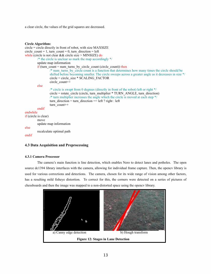
The camera’s main function is line detection, which enables Nero to detect lanes and potholes. The open source dc1394 library interfaces with the camera, allowing for individual frame capture. Then, the opencv library is
used for various corrections and detections. The camera, chosen for its wide range of vision among other factors, has a resulting mild fisheye distortion. To correct for this, the corners were detected on a series of pictures of
chessboards and then the image was mapped to a non-distorted space using the opencv library.
a) Canny edge detection b) Hough transform
Figure 12: Stages in Lane Detection
13
Canny edge detection, implemented by opencv, is first used to identify edge points in the images. These detected edges serve as a starting point for a Hough transform. The Hough transform groups edge points together
and estimates the most likely parameters for a line through the points. See Figure 12. When the processor has determined that a line exists, it stores the direction of the line in a vector and passes it to the AI. For pothole
detection, Nero again relies on a Hough transform to fit a circle. The function Intersect Circle, used in the Circle Algorithm to determine whether a given circle is clear, determines whether or not there is a line or pothole in the
proposed circle.
4.3.2 Lane Following During the Autonomous Challenge, the first step in the algorithm is to check for any lane lines. If a lane
line has been detected by the camera processor, it returns a vector determining the direction of the line. This direction is set as the next direction for Nero to travel. For dashed lines, the camera will still return a vector in the
direction of the line and this will become the next direction for the robot. In between line segments, Nero will maintain the same direction, until the next line segment is detected and another command is passed to travel parallel
to the line.
4.3.3 LIDAR Processing The LIDAR is responsible for detecting all obstacles except for lines and potholes. The SICK toolbox
provides a collection of libraries to interface with the LIDAR. The function Intersect Circle works analogously to the function of the same name in the camera processor. The goal is to determine whether a given circle from the CA
is free of obstacles or not. Intersect Circle projects the circle currently considered by the algorithm onto the ray measurements given by the LIDAR. To speed up processing, only the data from the rays that intersect the proposed
circle are analyzed. An intersection occurs when the ray ends before or inside the circle, indicating that the circle is not clear. The number of such intersections is counted, and when this value passes a threshold constant to be
determined by testing the circle is determined to be not clear. The LIDAR is capable of detecting obstacles at a range of up to 30m, but the CA only requires detection of obstacles at a maximum range of the diameter of the
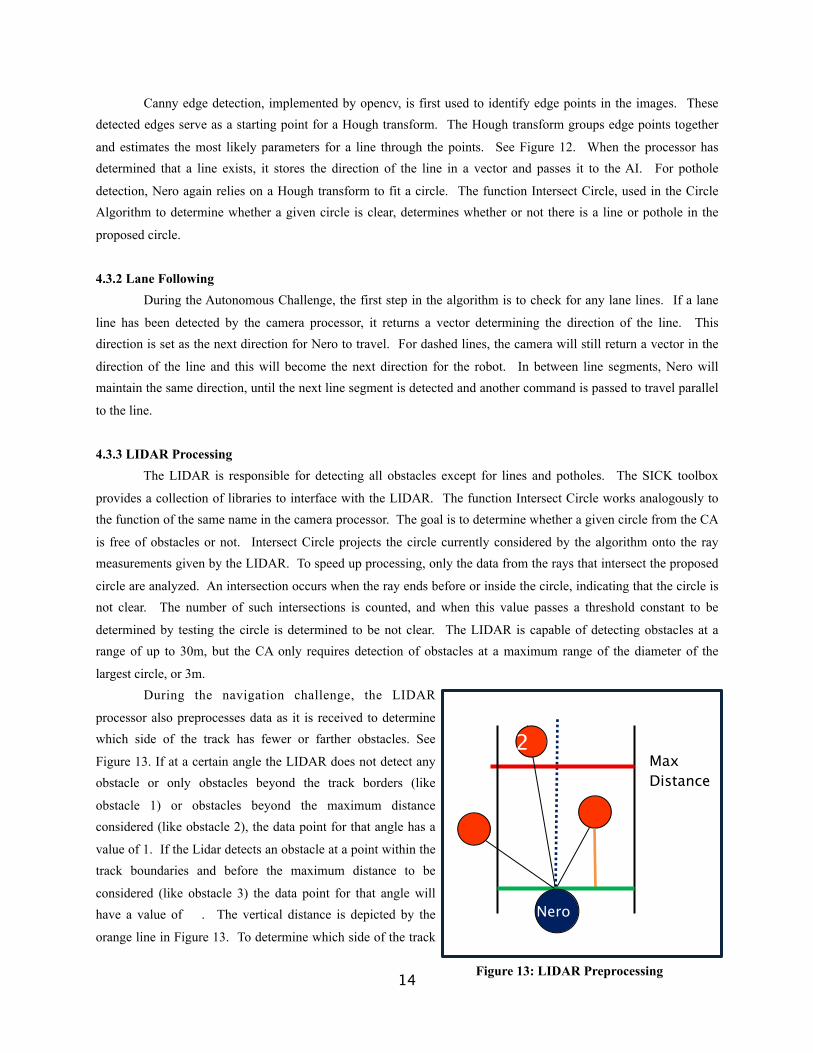
largest circle, or 3m.During the navigation challenge, the LIDAR
processor also preprocesses data as it is received to determine which side of the track has fewer or farther obstacles. See
Figure 13. If at a certain angle the LIDAR does not detect any obstacle or only obstacles beyond the track borders (like
obstacle 1) or obstacles beyond the maximum distance considered (like obstacle 2), the data point for that angle has a
value of 1. If the Lidar detects an obstacle at a point within the track boundaries and before the maximum distance to be
considered (like obstacle 3) the data point for that angle will have a value of . The vertical distance is depicted by the
orange line in Figure 13. To determine which side of the track
14
Max Distance
2
Nero
Figure 13: LIDAR Preprocessing
is better, the LIDAR processor sums all the values of the data points to the left and all the values of the data points to the right. The maximum of the two values indicates the side that contains the least or farthest obstacles and therefore
is the better side. Then the direction of travel can be altered accordingly.
4.4 Artificial Intelligence
4.4.1 Navigation Algorithm
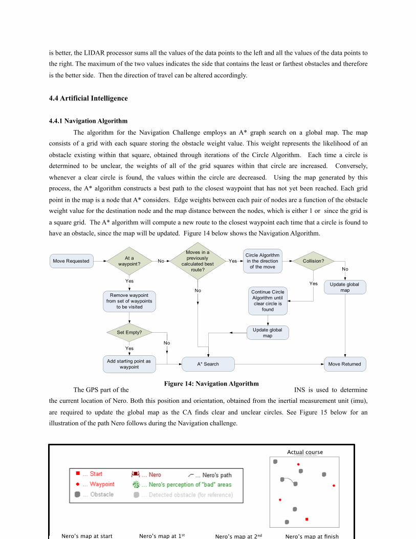
The algorithm for the Navigation Challenge employs an A* graph search on a global map. The map consists of a grid with each square storing the obstacle weight value. This weight represents the likelihood of an
obstacle existing within that square, obtained through iterations of the Circle Algorithm. Each time a circle is determined to be unclear, the weights of all of the grid squares within that circle are increased. Conversely,
whenever a clear circle is found, the values within the circle are decreased. Using the map generated by this process, the A* algorithm constructs a best path to the closest waypoint that has not yet been reached. Each grid
point in the map is a node that A* considers. Edge weights between each pair of nodes are a function of the obstacle weight value for the destination node and the map distance between the nodes, which is either 1 or since the grid is
a square grid. The A* algorithm will compute a new route to the closest waypoint each time that a circle is found to have an obstacle, since the map will be updated. Figure 14 below shows the Navigation Algorithm.
The GPS part of the INS is used to determine the current location of Nero. Both this position and orientation, obtained from the inertial measurement unit (imu),
are required to update the global map as the CA finds clear and unclear circles. See Figure 15 below for an illustration of the path Nero follows during the Navigation challenge.
15
Actual course
Nero’s map at start Nero’s map at 1st Nero’s map at 2nd Nero’s map at finish
Figure 14: Navigation Algorithm

4.4.2 Autonomous Strategy
The general strategy for the autonomous algorithm is to continue to move forward if no lanes are detected, keep track of orientation, and maintain a global orientation that will be updated regularly to ensure that Nero’s
orientation coincides with the global orientation. The AI will keep a stack of previous movements and speeds. Data from the INS processor, only obtained from the IMU, is used to keep track of orientation, allowing Nero’s past
movements to be defined as vectors. The global direction is determined by adding the vectors followed during the last x moves, x being a parameter to be adjusted during further testing. The algorithm is detailed in Figure 16. The
Modified Direction is determined to be validated or not according the Figure 17.
Figure 16: Autonomous Algorithm
Figure 17: Validation of Modified Direction
This algorithm will allow for navigation through switchbacks because the algorithm validates the modified
direction with the global direction to prevent backtracking. Center islands will be circumvented by the CA as in Figure
18. If there is an obstacle directly in front of Nero, the algorithm then considers a circle rotated to the left or right.
16
obstacle
Nero
Circle unclearCircle clear
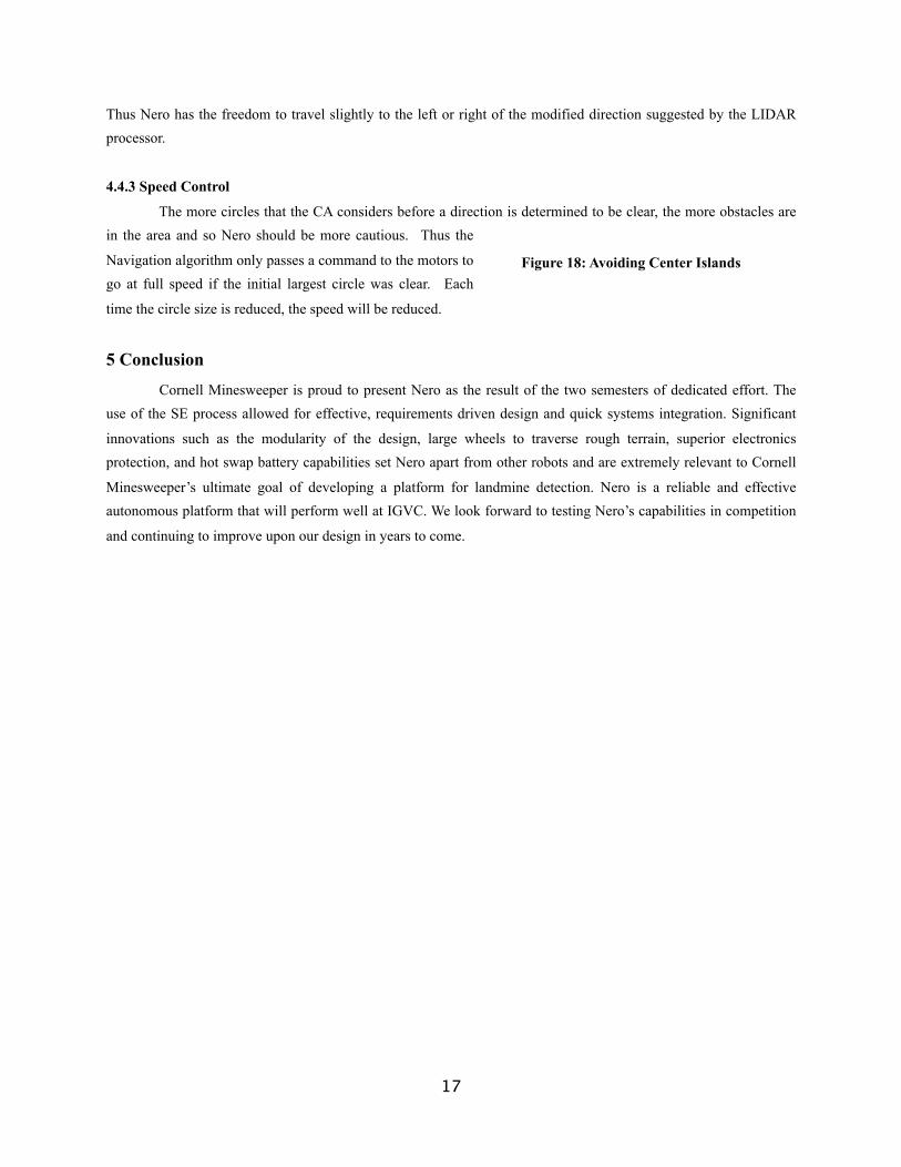
Thus Nero has the freedom to travel slightly to the left or right of the modified direction suggested by the LIDAR processor.
4.4.3 Speed Control
The more circles that the CA considers before a direction is determined to be clear, the more obstacles are in the area and so Nero should be more cautious. Thus the
Navigation algorithm only passes a command to the motors to go at full speed if the initial largest circle was clear. Each
time the circle size is reduced, the speed will be reduced.
5 Conclusion
Cornell Minesweeper is proud to present Nero as the result of the two semesters of dedicated effort. The use of the SE process allowed for effective, requirements driven design and quick systems integration. Significant
innovations such as the modularity of the design, large wheels to traverse rough terrain, superior electronics protection, and hot swap battery capabilities set Nero apart from other robots and are extremely relevant to Cornell
Minesweeper’s ultimate goal of developing a platform for landmine detection. Nero is a reliable and effective autonomous platform that will perform well at IGVC. We look forward to testing Nero’s capabilities in competition
and continuing to improve upon our design in years to come.
17
Figure 18: Avoiding Center Islands