Embed Size (px)
Citation preview
Copying Lens for Microfilm Photography
Berlyn Brixner
A new lens design for precise copying exemplifies the success of the rms error function as a suitable criteri-
on for the design of high resolution lenses. The design, a 145-mm f/4.0, gives 400-line/mm, high contrast,
white-light visual resolution throughout a 30-mm flat image when used at 20:1 conjugates. On high resolu-
tion plates, a resolution of 320 lines/mm is obtained. The five-glass design has no vignetting of the mar-
ginal beams, presents no manufacturing problems, and gave full resolution when first assembled. The pre-
scription was found by the LASL 1972 Lens Design Program.
Performance Specifications and Results
In this paper the way the LASL lens design pro-graml was used to design a special microfilm copylens for a LASL camera is illustrated. A new design
was needed because no commercial design could be
found to meet six of the requirements. Tight specifi-cations were necessary to prevent the loss of resolu-tion and image contrast at the field edge that charac-terized all the commercial lenses we tested that werecapable of producing precise reticles and printed cir-cuits. The specifications were drawn up with theprimary intention of correcting defects observed inthe best available lenses, and thus a new design wasdiscovered that gave excellent performance underour particular conditions of use.
The first specification, and the most difficult tosatisfy, was high resolution, preferably diffraction-limited (400 lines/mm), throughout the image field atf/4 relative aperture. The second specification was a30-mm-diam flat image field, needed for photograph-ing flat art work on plates and film. The third speci-fication was excellent rectilinearity, 0.01 mm maxi-mum error at any point in the field. This error limi-tation also includes the lateral chromatism. Fourth,we needed high contrast images to minimize imagespread with increasing film exposure. This last spec-ification meant that image flare had to be small.The fifth requirement was ability to copy at a reduc-tion of 20 to 1, a size convenient for our application.The sixth specification was red-green achromatiza-tion to permit the lens to be used with either mono-chromatic or white-light illumination. Red-blueachromatization, which is unnecessary, would lower
The author is with Los Alamos Scientific Laboratory, University
of California, Los Alamos, New Mexico 87544.
Received 13 December 1973.
resolution, because the red-blue chromatic errors aremuch larger than red-green.
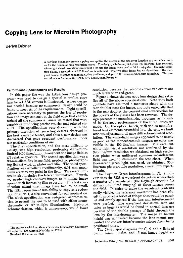
Figure 1 shows the new copy lens design that satis-fies all of the above specifications. Note that bothdoublets have assumed a meniscus shape with therear doublet near the image, and note especially thatin the rear doublet the conventional construction forthe powers of the glasses has been reversed. The de-sign presents no manufacturing problems, as indicat-ed by the good performance of the three lenses wemade. On the optical bench, with the as-manufac-tured lens elements assembled into the cells we builtwithout adjustment, all gave diffraction-limited reso-lution. The white-light images appeared to be nearlyas good as the monochromatic images; no color wasvisible in the 400-line/mm images. The excellentwhite-light visual resolution was confirmed by the320-line/mm resolution we obtained on high resolu-tion plates when unfiltered common incandescentlight was used to illuminate the test chart. Whenfluorescent green light was used, we obtained 350-line/mm photographic resolution, a small but expect-ed gain.
The Twyman-Green interferograms in Fig. 2 indi-cate that the 6328-A wavefront distortion is less thana quarter of a wavelength (the Rayleigh criterion fordiffraction-limited imaging) at three images acrossthe field. In order to make the wavefront contourseasily visible, the reference wavefront has been tilt-ed2 to produce a series of fringes that would be paral-lel and evenly spaced if the lens and interferometerwere perfect. The wavefront deviations seen aretwice as large as would be found in normal lens usebecause of the double passage of light through thelens by the interferometer. The image at 15-mmheight was not tested because the lens mount pre-vented the convex interferometer mirror from beingpositioned there.
The 52-ray spot diagrams for C, d, and e light at0-mm, 5-mm, 10-iim, and 15-mm image height are
September 1974 / Vol. 13, No. 9 / APPLIED OPTICS 2067
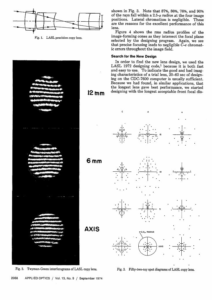
Fig. 1. LASL precision copy lens.
12tnm
shown in Fig. 3. Note that 87%, 86%, 76%, and 90%of the rays fall within a 2.5-A radius at the four imagepositions. Lateral chromatism is negligible. Theseare the reasons for the excellent performance of thislens.
Figure 4 shows the rms radius profiles of theimage-forming cones as they intersect the focal planeselected by the designing program. Again, we seethat precise focusing leads to negligible C-e chromat-ic errors throughout the image field.
Search for the New DesignIn order to find the new lens design, we used the
LASL 1972 designing code,' because it is both fastand easy to use. To indicate the good and bad imag-ing characteristics of a trial lens, 20-60 sec of design-ing on the CDC-7600 computer is usually sufficient.Because we had found, in similar applications, thatthe longest lens gave best performance, we starteddesigning with the longest acceptable front focal dis-
C d e
* * * -::-*
6mm
10
5
2 5~RADIUS
- - AXII
Fig. 2. Twyman-Green interferograms of LASL copy lens. Fig. 3. Fifty-two-ray spot diagrams of LASL copy lens.
2068 APPLIED OPTICS / Vol. 13, No. 9 / September 1974
AXIS
I
L.. -
. ... ... .
.04
.03
.02
.0115.00
.99
.98
.97.96
E .04E .03I- .02IA .01Al 10.00I .99WLJ .98
< .972 .96
.04
.03.02.01
5.00.99.98.97.96
6.16 6.17 6.18 6.19 6.20 6.21 6.22 6.23 6.24
BACK FOCAL DISTANCE,mm
Fig. 4. Image-forming cones (rms radius profiles) at focal plane of
LASL copy lens.
tance, 3048 mm, and used that value for all the pre-scriptions studied here. A lens of about 145-mmfocal length is needed to focus at this distance.
Because we did not know of a simple arrangementof glasses that would give the required performance,we decided to make a search, starting with a triplet.Afterwards, we added elements and rearranged thesequence of crown and flint glasses. BK-7 and F-4glasses (25 mm and 13 mm thick) were used becausethey were readily available and suitable. In order todesign and determine performance, we traced bun-dles of six rays in half the entrance pupil from theaxial and from three off-axis object points in d and elight. During all runs of this search, the weights (1.0for spot sizes, 0.2 for lateral errors, 10.0 for viola-tions) and the scale factor (1.0 for inch units) wereheld constant. After the designing procedure hadbeen tuned up for this particular problem, the de-signing and the printout of- the lens-performanceevaluation were often obtained in a single 30-sec run.We judged the design progress by noting two mainimage characteristics: (1) the maximum spot size tobe found among the images evaluated and (2) themaximum distortion and lateral chromatic errors,both of which, in this code, are tied together.
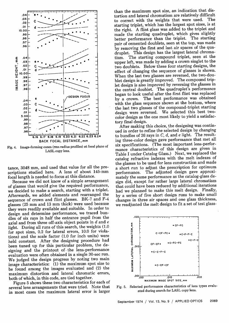
Figure 5 shows these two characteristics for each of
several lens arrangements that were tried. Note thatin most cases the maximum lateral error is larger
than the maximum spot size, an indication that dis-tortion and lateral chromatism are relatively difficultto correct with the weights that were used. Thestarting triplet, which has the largest spot sizes, is atthe right. A flint glass was added to the triplet andmade the starting quadruplet, which gives slightlybetter performance than the triplet. The startingpair of cemented doublets, seen at the top, was madeby removing the first and last air spaces of the qua-druplet. This design has the largest lateral chroma-tism. The starting compound triplet, seen at theupper left, was made by adding a crown singlet to thetwo doublets. Below these four starting designs, theeffect of changing the sequence of glasses is shown.When the last two glasses are reversed, the two-dou-blet design is greatly improved. The compound trip-let design is also improved by reversing the glasses inthe central doublet. The quadruplet's performancebegan to look useful after the first flint was replacedby a crown. The best performance was obtainedwith the glass sequence shown at the bottom, wherethe last two glasses of the compound-triplet startingdesign were reversed. We selected this best two-color design as the one most likely to yield a satisfac-tory final design.
After making this choice, the designing was contin-ued in order to refine the selected design by changingto bundles of 26 rays in C, d, and e light. The result-ing three-color design gave performance that met allsix specifications. (The most important lens-perfor-mance characteristics of this design are given inTable I under Catalog Glass.) Next, we replaced thecatalog refractive indexes with the melt indexes ofthe glasses to be used for lens construction and madea short run to adjust the prescription for optimumperformance. The adjusted design gave approxi-mately the same performance as the catalog-glass de-sign did, except for' rather large lateral chromatismthat could have been reduced by additional iterationshad we planned to make this melt design. Finally,by a series of five short design runs to make smallchanges in three air spaces and one glass thickness,we readjusted the melt design to fit a set of test glass-
E
4
0
_4
4
CF-FC
C-CF-FC * C-F-F-C
C-F-CCF-CF. * C-FC-FC
.010
c-C-F-C
C-CF-CF
001 _ I
MAXIMUM IMAGE SPOT SZE,mm
. AN
Fig. 5. Selected performance characteristics of lens types evalu-
ated during search for LASL copy lens.
September 1974 / Vol. 13, No. 9 / APPLIED OPTICS 2069
T-r r | I I , I
e . 1"/d- -~
~~~~~~0 I'
e
d
5 -C 5 5 "
~~~~~ * * * . .
-DESIGN FOCUS
__~~~~~~. _
*_ __ _
.......... I........ ,I...................
- C
_ d
_1111
~~~~~~~~~. . .. . . sr
-.............
I . .
.1
* 00}
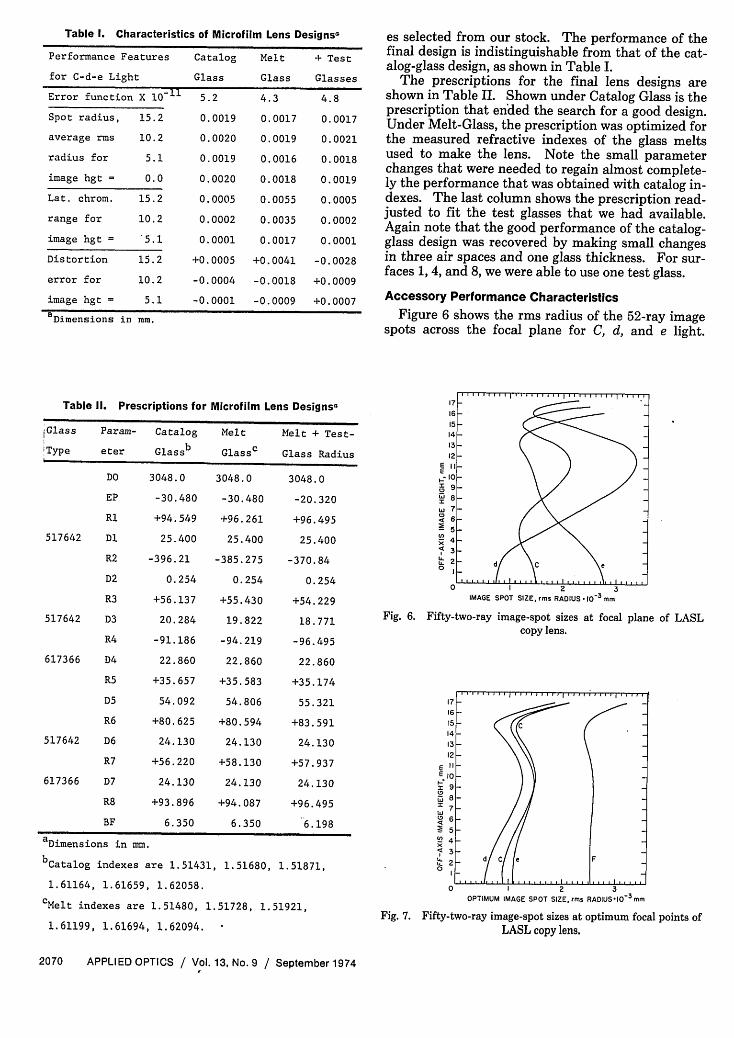
Table 1. Characteristics of Microfilm Lens Designs-
Performance Features Catalog Melt + Test
for C-d-e Light Glass Glass Glasses
Error function X 10-11 5.2 4.3 4.8
Spot radius, 15.2 0.0019 0.0017 0.0017
average ms 10.2 0.0020 0.0019 0.0021
radius for 5.1 0.0019 0.0016 0.0018
image hgt = 0.0 0.0020 0.0018 0.0019
Lat. chrom. 15.2 0.0005 0.0055 0.0005
range for 10.2 0.0002 0.0035 0.0002
image hgt = '5.1 0.0001 0.0017 0.0001
Distortion 15.2 +0.0005 +0.0041 -0.0028
error for 10.2 -0.0004 -0.0018 +0.0009
image hgt = 5.1 -0.0001 -0.0009 +0.0007
BDimensions in mm.
Table II. Prescriptions for Microfilm Lens Designsa
Glass Param- Catalog Melt Melt + Test-
Type eter Glassb Glass Glass Radius
DO 3048.0 3048.0 3048.0
EP -30.480 -30.480 -20.320
Rl +94.549 +96.261 +96.495
517642 DI 25.400 25.400 25.400
R2 -396.21 -385.275 -370.84
D2 0.254 0.254 0.254
R3 +56.137 +55.430 +54.229
517642 D3 20.284 19.822 18.771
R4 -91.186 -94.219 -96.495
617366 D4 22.860 22.860 22.860
R5 +35.657 +35.583 +35.174
D5 54.092 54.806 55.321
R6 +80.625 +80.594 +83.591
517642 D6 24.130 24.130 24.130
R7 +56.220 +58.130 +57.937
617366 D7 24.130 24.130 24.130
R8 +93.896 +94.087 +96.495
BF 6.350 6.350 6.198
aDimensions in mm.
bCatalog indexes are 1.51431, 1.51680, 1.51871,
1.61164, 1.61659, 1.62058.
CMelt indexes are 1.51480, 1.51728, 1.51921,
1.61199, 1.61694, 1.62094.
es selected from our stock. The performance of thefinal design is indistinguishable from that of the cat-alog-glass design, as shown in Table I.
The prescriptions for the final lens designs areshown in Table II. Shown under Catalog Glass is theprescription that ended the search for a good design.Under Melt-Glass, the prescription was optimized forthe measured refractive indexes of the glass meltsused to make the lens. Note the small parameterchanges that were needed to regain almost complete-ly the performance that was obtained with catalog in-dexes. The last column shows the prescription read-justed to fit the test glasses that we had available.Again note that the good performance of the catalog-glass design was recovered by making small changesin three air spaces and one glass thickness. For sur-faces 1, 4, and 8, we were able to use one test glass.
Accessory Performance CharacteristicsFigure 6 shows the rms radius of the 52-ray image
spots across the focal plane for C, d, and e light.
EE
ID
LI
M
4U.U.0
IMAGE SPOT SIZE, rms RADIUS 103 3mm
Fig. 6. Fifty-two-ray image-spot sizes at focal plane of LASLcopy lens.
EEI-.ID
4i
'A4
2
OPTIMUM IMAGE SPOT SIZE, rms RADIUSIO 3mm
Fig. 7. Fifty-two-ray image-spot sizes at optimum focal points ofLASL copy lens.
2070 APPLIED OPTICS / Vol. 13, No. 9 / September 1974

The excellent performance of this lens is a practi-cal example of the success of the rms error functionas a suitable criterion for the design of high resolu-tion lenses. The use of a design procedure that opti-mizes the whole image spot through statistical analy-sis exposes some traditional fallacies7 8 that havebeen inherited as part of the usual hand-computationmethod. In the Brixner system,' spot diagrams areoptimized because they closely resemble the actualimage of a point source, a resemblance confirmed assoon as spot-diagram production became feasible9
and now generally accepted.'0-' 3
BACK FOCUS, mm
Fig. 8. Fifty-two-ray astigmatic surfaces of LASL copy lens.
Here, the average spot size is about 2 g, even at thefield edge, 15 mm off axis. About 70% of the rays arecontained in the rms radius circle. Note that al-though the greatest variation in spot size is in d light,even in the region of the largest spots there is no no-ticeable loss of resolution when aerial or photograph-ic images are being viewed. If it were important, thesize of the d light spots, around 11 mm, could havebeen reduced by using a larger weight on that colorand image position.
Figure 7 shows the spot sizes at the optimum focalpositions throughout the image field. Note how sim-ilar the curves are for -C, d, e, and F. The positionand the shape of the F curve indicate that at theblue-light focus the lens should still make diffrac-tion-limited images, probably with some loss of con-trast. Visual tests qualitatively confirm that conclu-sion.
Figure 8 shows the 52-ray sagittal and tangentialfocal surfaces throughout the field for C, d, and elight. On the optical bench, this amount of astigma-tism is not noticeable. The F light curves are of sim-ilar shape, but at 6.4-mm back focus. Note thatthese curves are obtained by statistical analysis ofthe spot diagrams, which gives a precise evaluation ofthe astigmatism as it is measured visually on the op-tical bench. This data-processing procedures'4 isslowly gaining acceptance. 5' 6
Conclusion
In designing this f/4 microfilm copy lens, the de-sired aim of diffraction-limited resolution wasachieved after a search for a favorable arrangementof glasses. High resolution and high contrast wereobtained at the same time by means of the LASL lensdesign program that designs on the sizes and posi-tions of the image-spot diagrams.
The author thanks R. E, Lapp, W. J. Wynne, K. T.Imamura, B. N. Lenhart, and B. J. Montoya for theircareful attention to details while making and testingthis lens. The commercially manufactured glass ele-ments met all engineering specifications.
This work was done under the auspices of the U.S.Atomic Energy Commission.
References1. B. Brixner, Appl. Opt. 12, 2703 (1973).
2. F. Twyman, Prism and Lens Making (Hilger & Watts, Lon-don, 1952), pp. 429, 435.
3. B. Brixner, in Proceedings of Sixth International Congress onHigh-Speed Photography, The Hague-Scheveningen, Nether-lands, 1962, J. G. A. de Graff and P. Tegelaar, Eds. (TjeenkWillink & Zoon, Haarlem, Netherlands, 1963).
4. B. Brixner, Appl. Opt. 5, 1950 (1966).
5. A. B. Meinel, in Proceedings of Panel Discussion of Some Au-tomatic Methods of Lens Design, Washington, D.C., 1966, J. S.Courtney-Pratt, Ed. (SMPTE, New York, 1967), pp. 201-203,
209-210.6. T. H. Jamieson, Optimization Techniques in Lens Design
(American Elsevier, New York, 1971), pp. 63, 77, 79, 81.
7. R. R. Shannon, in Ref. 5, p. 207.
8. T. H. Jamieson, in Ref. 6, pp. 36-37.9. D. G. Hawkins and E. H. Linfoot, Mon. Not. R. Astron. Soc.
105, 343 (1945).10. M. Herzberger, J. Opt. Soc. Am. 37, 489 (1947).
11. E. H. Linfoot, Recent Advances in Optics (Oxford U.P., New
York, 1955), p. 224.12. M. Herzberger, Modern Geometrical Optics (Interscience,
New York, 1958), p. 287.13. R. Kingslake, in Applied Optics and Optical Engineering, R.
Kingslake, Ed. (Academic Press, New York, 1965), Vol. 3, p.
17.
September 1974 / Vol. 13, No. 9 / APPLIED OPTICS 2071
ID
E
x
40