Embed Size (px)
Citation preview
ENSC 833: (Network Protocols and Performance)
Convergence behavior
of the EIGRP –
Enhanced Interior Gateway Routing Protocol
http://come.to/ensc833
Hubert Pun
933021508
April 13, 2001
2
Abstract
When communicating within the computer network, routing and switching packets are
considered as the overhead; this is especially true for the resource-limited Wide Area
Network link where convergence must be fast and routing packet must be kept to
minimal. Enhanced Interior Gateway Routing Protocol (EIGRP), being one of the most
efficient routing protocols, can satisfy the objective stated above.
This paper begins with a discussion of the characteristic of different routing protocols.
Afterward, the EIGRP protocol itself will be investigated; topics that are included are:
metric calculation, Diffusing Update Algorithm, EIGRP terminology. Finally, EIGRP
behavior for different scenarios will be examined by using five Cisco routers. The cases
of both with and without a feasible successor will be compared; the k-values will also be
modified to simulate the delay-sensitive traffic and “effective” bandwidth in order to
observe any impact to the convergence time.
3
Table of Content
1. Introduction 1
2. Background Theory 2
2.1 Inter-domain vs. Intra-domain 2
2.2 Distance Vector vs. Link State 3
3. EIGRP 8
3.1 Metric 8
3.2 Terminology 10
3.3 DUAL 10
3.4 Example 11
3.5 Advantages and Disadvantages 12
4. My Experiments 14
4.1 Metric Calculation 15
4.2 Fail Over 19
4.3 Change k-values 20
4.4 Discussion 25
5. Conclusion 27
6. Reference 28
7. Abbreviation 29
Appendix A – Router Information 31
Appendix B – Code Listing 32
1
1. Introduction
In the computer networking industry, things are changing constantly. In the early day, it
was widely believed that using routers to build network was the most scalable method.
Then the emerging of switching technology made people believe that Layer two switches
yield the most scalable network. Nowadays, Multi-Layer Switch (MLS) combines the
functionality of Layer 2, 3 and 4; it is now the main technology for networking.
Routing protocol is the heartbeat of routing. There are several routing protocols
commonly used nowadays; but the most efficient ones are the Open Shortest Path First
(OSPF) and the Enhanced Interior Gateway Routing Protocol (EIGRP). This paper
introduces the background of routing protocol and the behavior of EIGRP. By using five
Cisco routers, the fail-over convergence behavior of EIGRP is examined, both with a
feasible successor and without a feasible successor. The k-values of the EIGRP metric
will also be modified to investigate the impact to the convergence.
Towards the end of the report, there is a glossary that lists all the acronyms used in this
paper. After that, the specifications of the five Cisco routers are listed. It is followed by
the “running configurations” that produce the results in this project.
2
2. Background Theory
In order to understand EIGRP, some basic networking concept must be understood. This
section contains a brief overview of the routing protocol. First, inter-domain routing and
intra-domain routing are introduced; then, the concept of distance vector and link-state
routing protocols are distinguished. The characteristics of several common routing
protocols are discussed too.
2.1 Inter domain vs. Intra domain
Before differentiating the difference between inter-domain and intra-domain routing
protocol, the term Autonomous System (AS) must be defined. An AS is a domain that is
under one administrative control. It usually uses one routing protocol and has a common
routing policy.
2.1.1 Inter-Domain
Inter-Domain routing routes packet between AS using Border Gateway Protocol
(BGP) version 4, the de-facto standard. The main routing objective for BGP is to
be able to control the flow of packets. For example, US military packets should
not travel a link that passes through Iraq. There are different attributes in BGP
that can be set to influence the incoming and outgoing traffic flow.
2.1.2 Intra-Domain
3
Intra-Domain routing routes packet within an AS. The main objective is to route
packet efficiently. There are various favors of Interior Gateway Protocol (IGP).
They can be grouped under two main categories: Distance Vector and Link State.
The following sections discuss and give examples to these two concepts.
2.2 Distance Vector vs. Link State
Distance vector and Link states are two families of intra-domain routing protocols. The
main difference lies in how the routing information is propagated. Both have their own
pros and cons. The network manager must decide himself which routing protocol best
suite his network environment.
2.2.1 Distance Vector
Distance Vector uses the Bellman Ford Algorithm. Each router would tell the
neighbor what it knows; then this neighbor would pass on this knowledge to the
next neighbor. It is similar to the scenario that one person passes his gossips to
the next person and so on.
One of the major disadvantages of distance vector routing protocol is its slow
convergence. It takes a long time for a router to detect changes of a far away
network. On the other hand, it consumes less CPU power. The following sub-
sections give examples of two routing protocols and also their characteristics.
2.2.1.1 RIP
4
Routing Information Protocol (RIP) is one of the first routing protocols that are
widely used in the Internet. The reason is simple; it comes for free with the
UNIX machine; it uses hop count as the metric measurement. On the good side, it
is simple to program on router; however, there are many disadvantages in addition
to the slow convergence issue. First, this is a classful routing protocol. If the
customer is running a subnet mask of /24 (255.255.255.0) on their network, then
the point-to-point serial link between the customer and the provider also needs a
/24 subnet mask in order for the routing information be exchanged. There are 254
usable IP address for this /24 subnet, but only two are used for the point-to-point
serial link; it wastes many IP addresses. In addition, the simple metric may cause
the router to choose sub-optimal route. A one-hop 56k slow link would be
preferred even the alternative route is T1 but two hops away. Finally, RIP only
supports a small network. Any destinations further than fifteen hops are
considered to be unreachable by RIP. Hence, the network diameter must be
within fifteen routers. It may work fine for the early Internet, but certainly not
realistic for nowadays’ huge inter-network.
2.2.1.2 IGRP
Interior Gateway Routing Protocol (IGRP) is the Cisco proprietary solution to
some of the RIP problems but still preserve the advantage of easy programming.
This is the second generation of Distance Vector routing protocol in a sense that it
uses a complex metric (involves bandwidth, delay, load and reliability) to solve
5
the RIP’s sub-optimal route problem. It also allows a network diameter of 255.
However, it is still a classful protocol and waste IP address space.
Due to its Cisco proprietary nature and the emerging of the Open Shortest Path
First (OSPF), IGRP is not as common as RIP or OSPF.
2.2.2 Link State
Link State routing protocol uses the Dijkstra’s algorithm. Basically, each router
floods its link state information to all other routers. Instead of getting second or
third hand information like DV, LS uses the first hand information. It makes LS
routing protocol converges much faster than DV. However, it is usually CPU
intensive and requires careful engineering.
2.2.2.1 OSPF
Open Shortest Path First (OSPF) was developed by the Internet Engineering Task
Force (IETF) as a replacement of the problematic RIP; it is now the IETF-
recommended Interior Gateway Protocol. It has many advantages: first, this is an
open standard (this is what the “O” in OSPF means); therefore, customers are not
constrained to a pure Cisco environment. In addition, it supports Variable Length
Subnet Mask (VLSM); the customer can have a /24 (255.255.255.0) subnet on
their end and a /30 (255.255.255.252) on the serial link and routing information
can still be transferred. This “classless” behavior prevents unneeded IP address
consumption. In addition, it convergences quickly. Since it uses Hello protocol

6
to detect the health of the neighbor, the fail over time would be less than 15
seconds. The metric is calculated as 108 / BW (in bps); it would prevent the sub-
optimal route possibility too. Finally, OSPF supports a hierarchy structure.
Routing information within one area would not consume the resource of another
area.
On the other hand, the main disadvantage of OSPF is that it only supports IP;
Inter-network Packet Exchange (IPX) or AppleTalk networks cannot enjoy the
benefit of OSPF. In addition, it is a demanding process; routers must have
enough memory and processing power to run OSPF. Finally, it is difficult to
implement and requires extensive engineering.
Despite the disadvantages listed above, the benefits of OSPF is overwhelming;
consequently, most of the commercial networks are using OSPF as their primary
Interior Gateway Protocol.
2.2.2.2 IS-IS
Intermediate System-Intermediate System (ISIS) routing protocol is an Open
System Interconnection (OSI) routing protocol. In 1986, the US government
issued the Government OSI Profile (GOSIP), which mandated OSI protocols for
future government use. IS-IS was initially often chosen over OSPF because the
US Government required support of ISO CLNP by networks in order to be
awarded federal contracts.
7
IS-IS behaves like OSPF. The main difference is that the entire router, instead of
just the interface like other routing protocol do, participates in the routing
protocol.
8
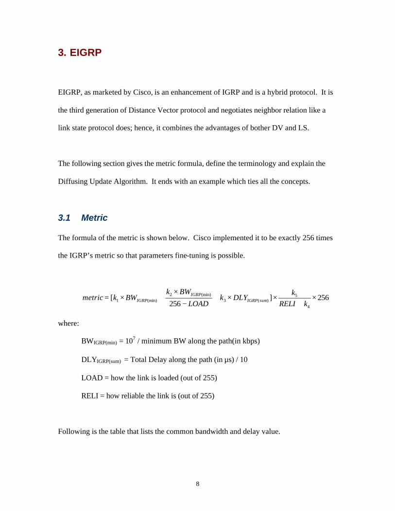
3. EIGRP
EIGRP, as marketed by Cisco, is an enhancement of IGRP and is a hybrid protocol. It is
the third generation of Distance Vector protocol and negotiates neighbor relation like a
link state protocol does; hence, it combines the advantages of bother DV and LS.
The following section gives the metric formula, define the terminology and explain the
Diffusing Update Algorithm. It ends with an example which ties all the concepts.
3.1 Metric
The formula of the metric is shown below. Cisco implemented it to be exactly 256 times
the IGRP’s metric so that parameters fine-tuning is possible.
256]256
[4
5)(3
(min)2(min)1 ×
+××+
−
×+×=
kRELIk
DLYkLOAD
BWkBWkmetric sumIGRP
IGRPIGRP
where:
BWIGRP(min) = 107 / minimum BW along the path(in kbps)
DLYIGRP(sum) = Total Delay along the path (in µs) / 10
LOAD = how the link is loaded (out of 255)
RELI = how reliable the link is (out of 255)
Following is the table that lists the common bandwidth and delay value.
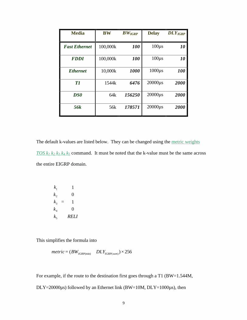
9
Media BW BWIGRP Delay DLYIGRP
Fast Ethernet 100,000k 100 100µs 10
FDDI 100,000k 100 100µs 10
Ethernet 10,000k 1000 1000µs 100
T1 1544k 6476 20000µs 2000
DS0 64k 156250 20000µs 2000
56k 56k 178571 20000µs 2000
The default k-values are listed below. They can be changed using the metric weights
TOS k1 k2 k3 k4 k5 command. It must be noted that the k-value must be the same across
the entire EIGRP domain.
=
RELIkkkkk
0101
5
4
3
2
1
This simplifies the formula into
256)( )((min) ×+= sumIGRPIGRP DLYBWmetric
For example, if the route to the destination first goes through a T1 (BW=1.544M,
DLY=20000µs) followed by an Ethernet link (BW=10M, DLY=1000µs), then

10
456,195,2256]21006476[256][
210010
100020000
6476154410
)((min)
)(
7
(min)
=×+=×+=
=+
=
==
sumIGRPIGRP
sumIGRP
IGRP
DLYBWmetric
ssDLY
BW
µµ
3.2 Terminology
There are many terms introduced by EIGRP. However, the most common are:
Feasible Distance (FD) = the best possible metric from source to destination.
Advertising Distance (AD) = the FD of the advertising router.
Successor = next hop router for the best route.
Feasible Successor (FS) = back up of next hop that satisfy the “feasible condition”.
3.3 DUAL
J.J. Garcia-Luna-Aceves developed the Diffusing Update Algorithm (DUAL). The
philosophy behind is that in order to guarantee a loop-free route, the feasible successor’s
advertising distance must be smaller than the source’s feasible distance. Section 3.4 has
an example to clarify this concept.
When there is an error on the primary link, then it would check whether a FS exist or not.
If there is one, it would immediately change the next hop to the FS. No calculation is
needed; thus the convergence is instantaneous. However, if there is no FS, then it is
necessary to run the DUAL to find the new successor.
11
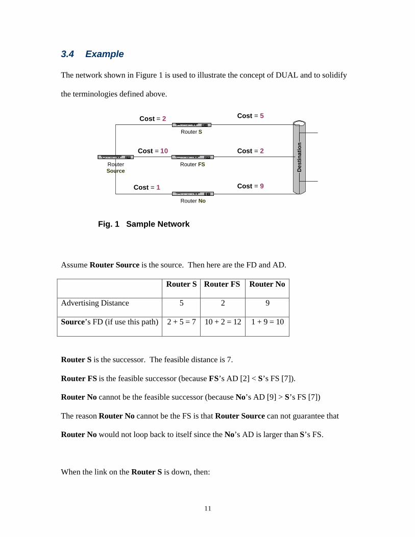
3.4 Example
The network shown in Figure 1 is used to illustrate the concept of DUAL and to solidify
the terminologies defined above.
Des
tin
atio
n
RouterSource
Router S
Router No
Router FS
Cost = 5
Cost = 2
Cost = 9
Cost = 2
Cost = 10
Cost = 1
Fig. 1 Sample Network
Assume Router Source is the source. Then here are the FD and AD.
Router S Router FS Router No
Advertising Distance 5 2 9
Source’s FD (if use this path) 2 + 5 = 7 10 + 2 = 12 1 + 9 = 10
Router S is the successor. The feasible distance is 7.
Router FS is the feasible successor (because FS’s AD [2] < S’s FS [7]).
Router No cannot be the feasible successor (because No’s AD [9] > S’s FS [7])
The reason Router No cannot be the FS is that Router Source can not guarantee that
Router No would not loop back to itself since the No’s AD is larger than S’s FS.
When the link on the Router S is down, then:
12
Router FS is the new successor with the FD = 12.
Router No can be a Feasible Successor because it’s AD (9) is less than Router Source’s
new FS (12).
3.5 Advantages and Disadvantages
There are several outstanding advantages using EIGRP. First, it supports multi network
layer routed protocols, namely, the Internet Protocol (IP), Inter-network Packet Exchange
(IPX) and AppleTalk (AT). This is a huge advantage for the non-TCP/IP oriented
networks. It greatly simplifies the router configuration by using the same routing
protocol across different platforms. In addition, the convergence time for EIGRP is very
fast. If there is a FS for the destination, the convergence time is almost instantaneous. If
there is no FS for the destination, it is necessary to run DUAL but the convergence time,
even for a huge network, is still lesser than 20 seconds. Finally, it is classless and
supports VLSM; consequently, a /30 (255.255.255.0) address space (two usable IP
addresses) is allocated to the point-to-point serial link while the customer network can
have some other subnet mask (e.g. /24 or 255.255.255.0).
On the other hand, the main reason why EIGRP is not as common as OSPF is because of
its proprietary nature. Network manager hesitates to commit to a pure Cisco
environment; any network with one non-Cisco node (e.g. TimeLAN, Bay or Nortel) can
not use EIGRP. Moreover, smart routing protocols usually are CPU bandwidth intensive.
If one of the destination networks that do not have a FS is very unstable, a lot of traffic
13
will be generated and it will consume plenty of bandwidth. In order to eliminate this
problem, the following three commands:
ip bandwidth-percent eigrp AS# number-of-%
ipx bandwidth-percent eigrp AS# number-of-%
appletalk eigrp-bandwidth-percent number-of-%
are used to control the percentages of bandwidth that the EIGRP process can take up.
This is especially useful for the Wide Area Network (WAN) link.
14
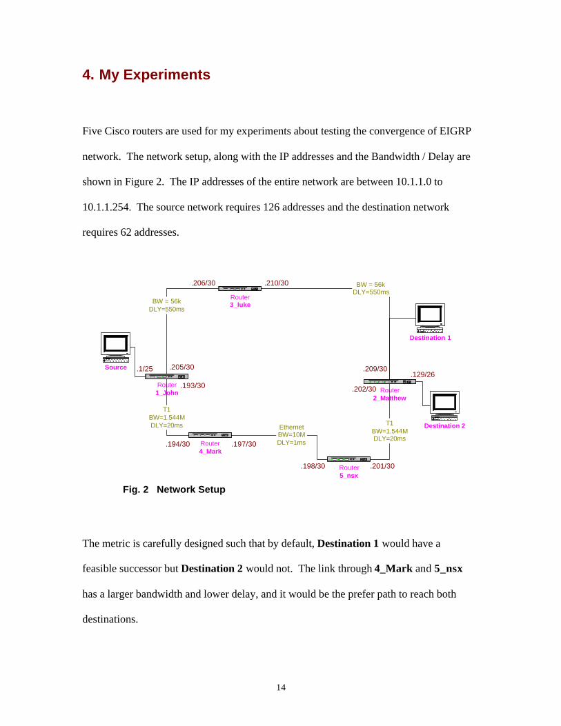
4. My Experiments
Five Cisco routers are used for my experiments about testing the convergence of EIGRP
network. The network setup, along with the IP addresses and the Bandwidth / Delay are
shown in Figure 2. The IP addresses of the entire network are between 10.1.1.0 to
10.1.1.254. The source network requires 126 addresses and the destination network
requires 62 addresses.
Router1_John
Router3_luke
Router4_Mark
Router2_Matthew
Router5_nsx
EthernetBW=10MDLY=1ms
T1BW=1.544MDLY=20ms
BW = 56kDLY=550ms
T1BW=1.544MDLY=20ms
BW = 56kDLY=550ms
Source
Destination 2
Fig. 2 Network Setup
.193/30
.194/30 .197/30
.198/30 .201/30
.202/30
.205/30
.206/30 .210/30
.209/30.1/25.129/26
Destination 1
The metric is carefully designed such that by default, Destination 1 would have a
feasible successor but Destination 2 would not. The link through 4_Mark and 5_nsx
has a larger bandwidth and lower delay, and it would be the prefer path to reach both
destinations.
15
4.1 Metric Calculation
As shown below are the metric calculation for the default k values.
4.1.1 Destination 1 (10.1.1.208/30)
The best path and the FD from the Source to the Destination 1 will be:
Source à 1_John à 4_Mark à 5_nsx à 2_Matthew à Destination 1
776,843,60256]59100178571[
5910010
55000020000100020000
1785715610
)(
7
(min)
=×+=
=+++
=
==
metric
ssssDLY
BW
sumIGRP
IGRP
µµµµ
There will also be a backup path from Source to the Destination 1; the feasible-
successor will be 3_luke. It is because the Advertising Distance of 3_luke is
smaller than the feasible distance of 1_John.
Source à 1_John à 3_luke à Destination 1
776,843,60176,794,59256]55000178571[
5500010
550000
17857156
10
)(
7
(min)
<=×+=
==
==
metric
sDLY
BW
sumIGRP
IGRP
µ
The actual distance of the backup route is:
176,874,73256]110000178571[
11000010
550000550000
1785715610
)(
7
(min)
=×+=
=+
=
==
metric
ssDLY
BW
sumIGRP
IGRP
µµ

16
4.1.2 Destination 2 (10.1.1.128/26)
The best path and the FD from the Source to the Destination 2 will be:
Source à 1_John à 4_Mark à 5_nsx à 2_Matthew à Destination 2
456,707,2256]41006476[
410010
20000100020000
6476154410
)(
7
(min)
=×+=
=++
=
==
metric
sssDLY
BW
sumIGRP
IGRP
µµµ
The following route is not the back-up route:
Source à 1_John à 3_luke à 2_Matthew à Destination 2
It is because the advertising distance of 3_luke is larger than the feasible distance
of 1_John.
456,707,2776,819,59256]55100178571[
5510010
100550000
1785715610
)(
7
(min)
>=×+=
=+
=
==
metric
ssDLY
BW
sumIGRP
IGRP
µµ
Just a note of curiosity: the actual distance if using this route is:
776,899,73256]110100178571[
11010010
100550000550000
1785715610
)(
7
(min)
=×+=
=++
=
==
metric
sssDLY
BW
sumIGRP
IGRP
µµµ
4.1.2 Router 1_John’s “Show” Commands
17
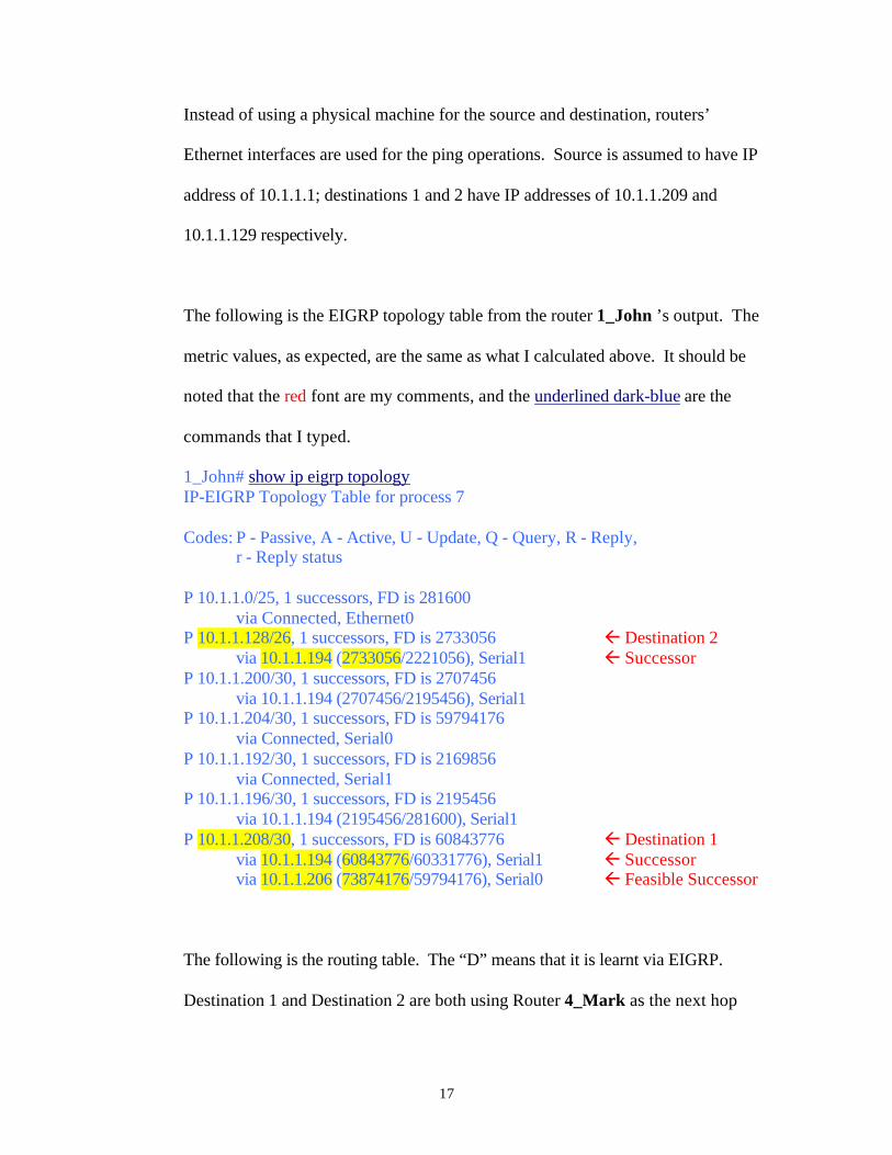
Instead of using a physical machine for the source and destination, routers’
Ethernet interfaces are used for the ping operations. Source is assumed to have IP
address of 10.1.1.1; destinations 1 and 2 have IP addresses of 10.1.1.209 and
10.1.1.129 respectively.
The following is the EIGRP topology table from the router 1_John ’s output. The
metric values, as expected, are the same as what I calculated above. It should be
noted that the red font are my comments, and the underlined dark-blue are the
commands that I typed.
1_John# show ip eigrp topology IP-EIGRP Topology Table for process 7 Codes: P - Passive, A - Active, U - Update, Q - Query, R - Reply,
r - Reply status P 10.1.1.0/25, 1 successors, FD is 281600
via Connected, Ethernet0 P 10.1.1.128/26, 1 successors, FD is 2733056 ß Destination 2
via 10.1.1.194 (2733056/2221056), Serial1 ß Successor P 10.1.1.200/30, 1 successors, FD is 2707456
via 10.1.1.194 (2707456/2195456), Serial1 P 10.1.1.204/30, 1 successors, FD is 59794176
via Connected, Serial0 P 10.1.1.192/30, 1 successors, FD is 2169856
via Connected, Serial1 P 10.1.1.196/30, 1 successors, FD is 2195456
via 10.1.1.194 (2195456/281600), Serial1 P 10.1.1.208/30, 1 successors, FD is 60843776 ß Destination 1
via 10.1.1.194 (60843776/60331776), Serial1 ß Successor via 10.1.1.206 (73874176/59794176), Serial0 ß Feasible Successor
The following is the routing table. The “D” means that it is learnt via EIGRP.
Destination 1 and Destination 2 are both using Router 4_Mark as the next hop
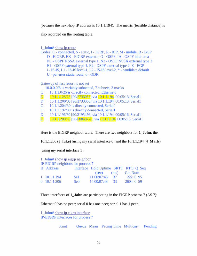
18
(because the next-hop IP address is 10.1.1.194). The metric (feasible distance) is
also recorded on the routing table.
1_John# show ip route Codes: C - connected, S - static, I - IGRP, R - RIP, M - mobile, B - BGP D - EIGRP, EX - EIGRP external, O - OSPF, IA - OSPF inter area N1 - OSPF NSSA external type 1, N2 - OSPF NSSA external type 2 E1 - OSPF external type 1, E2 - OSPF external type 2, E - EGP i - IS-IS, L1 - IS-IS level-1, L2 - IS-IS level-2, * - candidate default U - per-user static route, o - ODR Gateway of last resort is not set 10.0.0.0/8 is variably subnetted, 7 subnets, 3 masks C 10.1.1.0/25 is directly connected, Ethernet0 D 10.1.1.128/26 [90/2733056] via 10.1.1.194, 00:05:13, Serial1 D 10.1.1.200/30 [90/2733056] via 10.1.1.194, 00:05:13, Serial1 C 10.1.1.204/30 is directly connected, Serial0 C 10.1.1.192/30 is directly connected, Serial1 D 10.1.1.196/30 [90/2195456] via 10.1.1.194, 00:05:16, Serial1 D 10.1.1.208/30 [90/60843776] via 10.1.1.194, 00:05:13, Serial1
Here is the EIGRP neighbor table. There are two neighbors for 1_John: the
10.1.1.206 (3_luke) [using my serial interface 0] and the 10.1.1.194 (4_Mark)
[using my serial interface 1].
1_John# show ip eigrp neighbor IP-EIGRP neighbors for process 7 H Address Interface Hold Uptime SRTT RTO Q Seq (sec) (ms) Cnt Num 1 10.1.1.194 Se1 11 00:07:46 37 222 0 95 0 10.1.1.206 Se0 14 00:07:48 33 2604 0 59
Three interfaces of 1_John are participating in the EIGRP process 7 (AS 7):
Ethernet 0 has no peer; serial 0 has one peer; serial 1 has 1 peer.
1_John# show ip eigrp interface IP-EIGRP interfaces for process 7 Xmit Queue Mean Pacing Time Multicast Pending
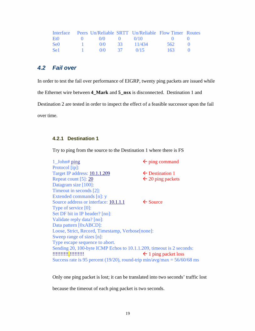
19
Interface Peers Un/Reliable SRTT Un/Reliable Flow Timer Routes Et0 0 0/0 0 0/10 0 0 Se0 1 0/0 33 11/434 562 0 Se1 1 0/0 37 0/15 163 0
4.2 Fail over
In order to test the fail over performance of EIGRP, twenty ping packets are issued while
the Ethernet wire between 4_Mark and 5_nsx is disconnected. Destination 1 and
Destination 2 are tested in order to inspect the effect of a feasible successor upon the fail
over time.
4.2.1 Destination 1
Try to ping from the source to the Destination 1 where there is FS
1_John# ping ß ping command Protocol [ip]: Target IP address: 10.1.1.209 ß Destination 1 Repeat count [5]: 20 ß 20 ping packets Datagram size [100]: Timeout in seconds [2]: Extended commands [n]: y Source address or interface: 10.1.1.1 ß Source Type of service [0]: Set DF bit in IP header? [no]: Validate reply data? [no]: Data pattern [0xABCD]: Loose, Strict, Record, Timestamp, Verbose[none]: Sweep range of sizes [n]: Type escape sequence to abort. Sending 20, 100-byte ICMP Echos to 10.1.1.209, timeout is 2 seconds: !!!!!!!!!!.!!!!!!!!! ß 1 ping packet loss Success rate is 95 percent (19/20), round-trip min/avg/max = 56/60/68 ms
Only one ping packet is lost; it can be translated into two seconds’ traffic lost
because the timeout of each ping packet is two seconds.
20
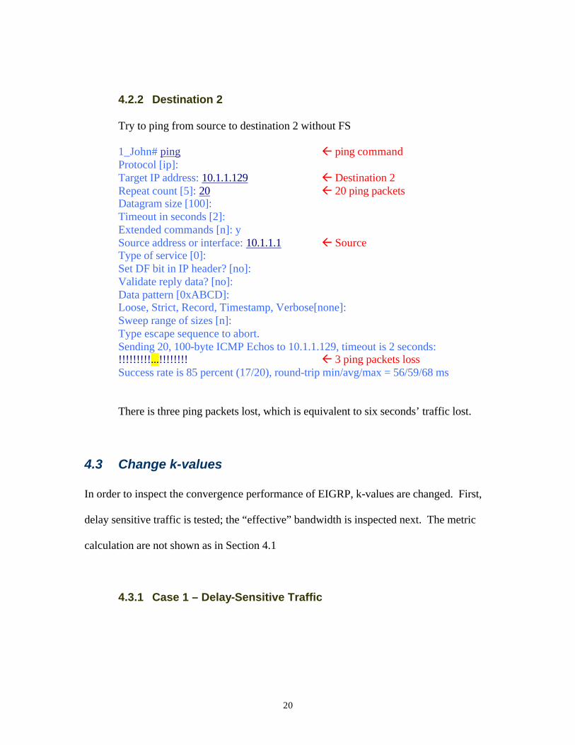
4.2.2 Destination 2
Try to ping from source to destination 2 without FS
1_John# ping ß ping command Protocol [ip]: Target IP address: 10.1.1.129 ß Destination 2 Repeat count [5]: 20 ß 20 ping packets Datagram size [100]: Timeout in seconds [2]: Extended commands [n]: y Source address or interface: 10.1.1.1 ß Source Type of service [0]: Set DF bit in IP header? [no]: Validate reply data? [no]: Data pattern [0xABCD]: Loose, Strict, Record, Timestamp, Verbose[none]: Sweep range of sizes [n]: Type escape sequence to abort. Sending 20, 100-byte ICMP Echos to 10.1.1.129, timeout is 2 seconds: !!!!!!!!!...!!!!!!!! ß 3 ping packets loss Success rate is 85 percent (17/20), round-trip min/avg/max = 56/59/68 ms
There is three ping packets lost, which is equivalent to six seconds’ traffic lost.
4.3 Change k-values
In order to inspect the convergence performance of EIGRP, k-values are changed. First,
delay sensitive traffic is tested; the “effective” bandwidth is inspected next. The metric
calculation are not shown as in Section 4.1
4.3.1 Case 1 – Delay-Sensitive Traffic

21
Delay is an important factor to be considered for traffic such as video
conferencing or telnet. Network managers desire to penalize the link where delay
is great; consequently, the k3 value is changed from one to three such that
256]3[ )((min) ×⋅+= sumIGRPIGRP DLYBWmetric
Since the k-values are changed, the metric values would be different. According
to the show command displayed below, the feasible distances to Destination 1 and
Destination 2 are increased to 91,102,976 and 4,883,456 respectively.
1_John# show ip eigrp topology IP-EIGRP Topology Table for process 7 Codes: P - Passive, A - Active, U - Update, Q - Query, R - Reply,
r - Reply status P 10.1.1.0/25, 1 successors, FD is 281600
via Connected, Ethernet0 P 10.1.1.128/26, 1 successors, FD is 4883456
via 10.1.1.194 (4883456/3347456), Serial1 P 10.1.1.200/30, 1 successors, FD is 4806656
via 10.1.1.194 (4806656/3270656), Serial1 P 10.1.1.204/30, 1 successors, FD is 59794176
via Connected, Serial0 P 10.1.1.192/30, 1 successors, FD is 2169856
via Connected, Serial1 P 10.1.1.196/30, 1 successors, FD is 3270656
via 10.1.1.194 (3270656/332800), Serial1 P 10.1.1.208/30, 1 successors, FD is 91102976
via 10.1.1.194 (91102976/89566976), Serial1 via 10.1.1.206 (130194176/87954176), Serial0
4.3.1.1 Destination 1 (with FS)
Twenty ping packets are sent between the source and Destination 1. Three
packets are lost; it averages to six seconds of missing traffic.
1_John# ping
22
Protocol [ip]: Target IP address: 10.1.1.209 Repeat count [5]: 20 Datagram size [100]: Timeout in seconds [2]: Extended commands [n]: y Source address or interface: 10.1.1.1 Type of service [0]: Set DF bit in IP header? [no]: Validate reply data? [no]: Data pattern [0xABCD]: Loose, Strict, Record, Timestamp, Verbose[none]: Sweep range of sizes [n]: Type escape sequence to abort. Sending 20, 100-byte ICMP Echos to 10.1.1.209, timeout is 2 seconds: !!!!!!!!...!!!!!!!!! Success rate is 85 percent (17/20), round-trip min/avg/max = 56/60/68 ms
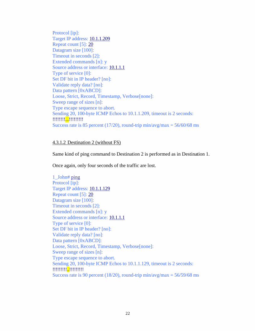
4.3.1.2 Destination 2 (without FS)
Same kind of ping command to Destination 2 is performed as in Destination 1.
Once again, only four seconds of the traffic are lost.
1_John# ping Protocol [ip]: Target IP address: 10.1.1.129 Repeat count [5]: 20 Datagram size [100]: Timeout in seconds [2]: Extended commands [n]: y Source address or interface: 10.1.1.1 Type of service [0]: Set DF bit in IP header? [no]: Validate reply data? [no]: Data pattern [0xABCD]: Loose, Strict, Record, Timestamp, Verbose[none]: Sweep range of sizes [n]: Type escape sequence to abort. Sending 20, 100-byte ICMP Echos to 10.1.1.129, timeout is 2 seconds: !!!!!!!!!..!!!!!!!!! Success rate is 90 percent (18/20), round-trip min/avg/max = 56/59/68 ms

23
Comparing to the average of five seconds traffic lost for the default k-values,
varying the weight on the delay parameter would not change the convergence
performance.
4.3.2 Case 2 – “Effective” Bandwidth
Instead of assigning a static value to the weight of bandwidth, “effective”
bandwidth would scale the importance of bandwidth. As the load increase, the
metric increases which makes the link to be less desirable. In this case, the k-
values are assigned such that k1 = 0, k2 = 255. Then, the metric formula is:
256])256
255[( )((min) ×+×
−= sumIGRPIGRP DLYBW
LOADmetric
In order to vary the LOAD, a lot of traffic is sent in the background. To be
specific, there are three ping commands occurring, each ping command consists
of 1000 packets that are of the size of 5000 bytes.
It can be shown from the show interface serial 1 command that the load on the
interface is 6/255, or approximately 2.4%.
1_John# show interface serial 1 Serial1 is up, line protocol is up Hardware is HD64570 Internet address is 10.1.1.193/30 MTU 1500 bytes, BW 1544 Kbit, DLY 20000 usec, rely 255/255, load 6/255 Encapsulation HDLC, loopback not set, keepalive set (10 sec) Last input 00:00:00, output 00:00:00, output hang never Last clearing of "show interface" counters never Input queue: 2/75/0 (size/max/drops); Total output drops: 0 Queueing strategy: weighted fair Output queue: 2/1000/64/0 (size/max total/threshold/drops)
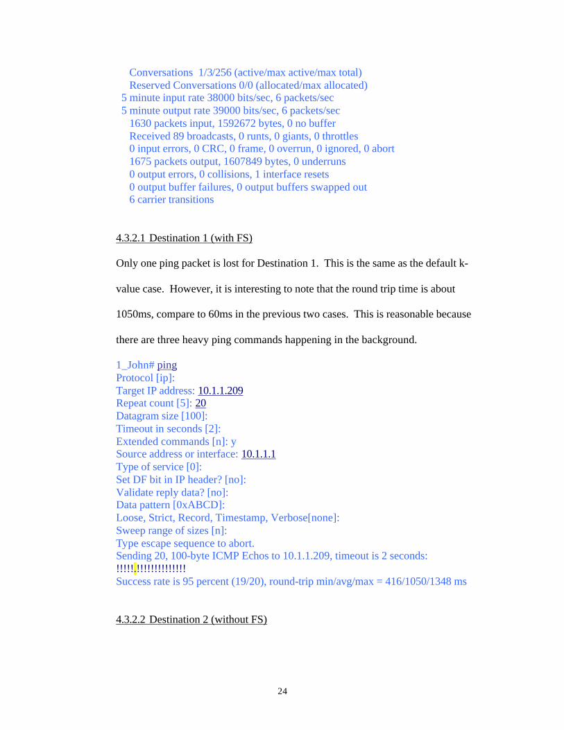
24
Conversations 1/3/256 (active/max active/max total) Reserved Conversations 0/0 (allocated/max allocated) 5 minute input rate 38000 bits/sec, 6 packets/sec 5 minute output rate 39000 bits/sec, 6 packets/sec 1630 packets input, 1592672 bytes, 0 no buffer Received 89 broadcasts, 0 runts, 0 giants, 0 throttles 0 input errors, 0 CRC, 0 frame, 0 overrun, 0 ignored, 0 abort 1675 packets output, 1607849 bytes, 0 underruns 0 output errors, 0 collisions, 1 interface resets 0 output buffer failures, 0 output buffers swapped out 6 carrier transitions
4.3.2.1 Destination 1 (with FS)
Only one ping packet is lost for Destination 1. This is the same as the default k-
value case. However, it is interesting to note that the round trip time is about
1050ms, compare to 60ms in the previous two cases. This is reasonable because
there are three heavy ping commands happening in the background.
1_John# ping Protocol [ip]: Target IP address: 10.1.1.209 Repeat count [5]: 20 Datagram size [100]: Timeout in seconds [2]: Extended commands [n]: y Source address or interface: 10.1.1.1 Type of service [0]: Set DF bit in IP header? [no]: Validate reply data? [no]: Data pattern [0xABCD]: Loose, Strict, Record, Timestamp, Verbose[none]: Sweep range of sizes [n]: Type escape sequence to abort. Sending 20, 100-byte ICMP Echos to 10.1.1.209, timeout is 2 seconds: !!!!!.!!!!!!!!!!!!!! Success rate is 95 percent (19/20), round-trip min/avg/max = 416/1050/1348 ms
4.3.2.2 Destination 2 (without FS)
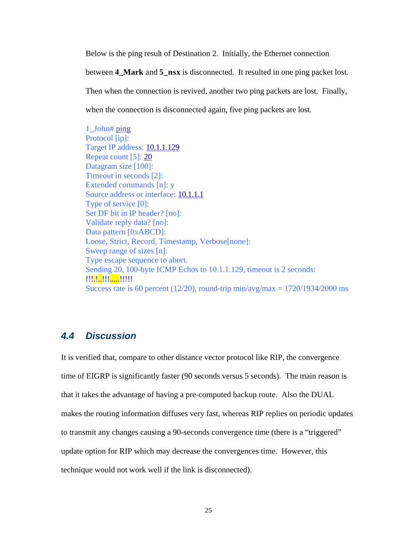
25
Below is the ping result of Destination 2. Initially, the Ethernet connection
between 4_Mark and 5_nsx is disconnected. It resulted in one ping packet lost.
Then when the connection is revived, another two ping packets are lost. Finally,
when the connection is disconnected again, five ping packets are lost.
1_John# ping Protocol [ip]: Target IP address: 10.1.1.129 Repeat count [5]: 20 Datagram size [100]: Timeout in seconds [2]: Extended commands [n]: y Source address or interface: 10.1.1.1 Type of service [0]: Set DF bit in IP header? [no]: Validate reply data? [no]: Data pattern [0xABCD]: Loose, Strict, Record, Timestamp, Verbose[none]: Sweep range of sizes [n]: Type escape sequence to abort. Sending 20, 100-byte ICMP Echos to 10.1.1.129, timeout is 2 seconds: !!!.!..!!!.....!!!!! Success rate is 60 percent (12/20), round-trip min/avg/max = 1720/1934/2000 ms
4.4 Discussion
It is verified that, compare to other distance vector protocol like RIP, the convergence
time of EIGRP is significantly faster (90 seconds versus 5 seconds). The main reason is
that it takes the advantage of having a pre-computed backup route. Also the DUAL
makes the routing information diffuses very fast, whereas RIP replies on periodic updates
to transmit any changes causing a 90-seconds convergence time (there is a “triggered”
update option for RIP which may decrease the convergences time. However, this
technique would not work well if the link is disconnected).
26
My experiment consists of three cases. First, the default k-values are used. For both
scenarios, only 5 seconds of traffic are lost. The next case uses a delay-sensitive formula
to calculate the metric; also 5 seconds of traffic are lost. Finally, an “effective”
bandwidth method is deployed; even though the round trip time is slow, only 5 seconds
of traffic is lost. It is apparent that changing the k-value would not vary the convergence
time significantly. Therefore I recommend that, the effort should be spent on the
following two items instead of trying different k-value. A better hierarchy topology can
isolate the flip-flopping routes and minimize the traffic going through the WAN link. In
addition, a well-designed IP addressing scheme permits route summarization, which
would minimize the size of the routing table.
27
5. Conclusion
EIGRP, being one of the most efficient routing protocols, has many advantages. It is
better than the traditional distance vector protocol (e.g. RIP and IGRP) because of its
classless and fast convergence properties. In addition, the fact that it supports IP, IPX
and AppleTalk outruns OSPF. However, the Cisco proprietary nature of this protocol
greatly limits the usefulness of EIGRP. Customer must have a pure Cisco environment in
order to deploy EIGRP. That’s why this is not as widely spread as OSPF.
I have investigated the convergence behavior of EIGRP using five Cisco routers. It has
been confirmed that the convergence time is very fast; only a few ping packets are lost.
This is true regarding there is a feasible successor for the destination or not. In addition,
two different k-values are examined. They are the delay-sensitive traffic and the
“effective” bandwidth. I have found that there is no dramatic difference on the
convergence behavior between the different cases. Hence, I recommend that the effort
should be spent on designing a scalable hierarchy structure instead.
28
6. References
[1] Jeff Doyles, CCIE Professional Development: Routing TCP/IP, Vol. 1, Cisco Press,
January 1998
[2] Michael Saterlee, Stephen Hutnik, Cisco CCIE All-in-One Lab Study Guide Oracle
Press, September 1999
[3] Andrew Caslow, Cisco Certification: Bridges, Routers & Switches for CCIEs,
Prentice-Hall Of Canada Ltd, December 1998
[4] Enhanced Interior Gateway Routing Protocol –
http://www.cisco.com/univercd/cc/td/doc/cisintwk/ito_doc/en_igrp.htm
[5] Introduction to Enhanced IGRP – http://www.cisco.com/warp/public/103/1.html
[6] Certification Zone – http://www.certificationzone.com (need log-in ID)
[7] Laura Chappell, Advanced Cisco Router Configuration, Cisco Press, 1999
[8] Bassam Halabi , Internet Routing Architectures 2nd Edition, Cisco Press, August
2000
29
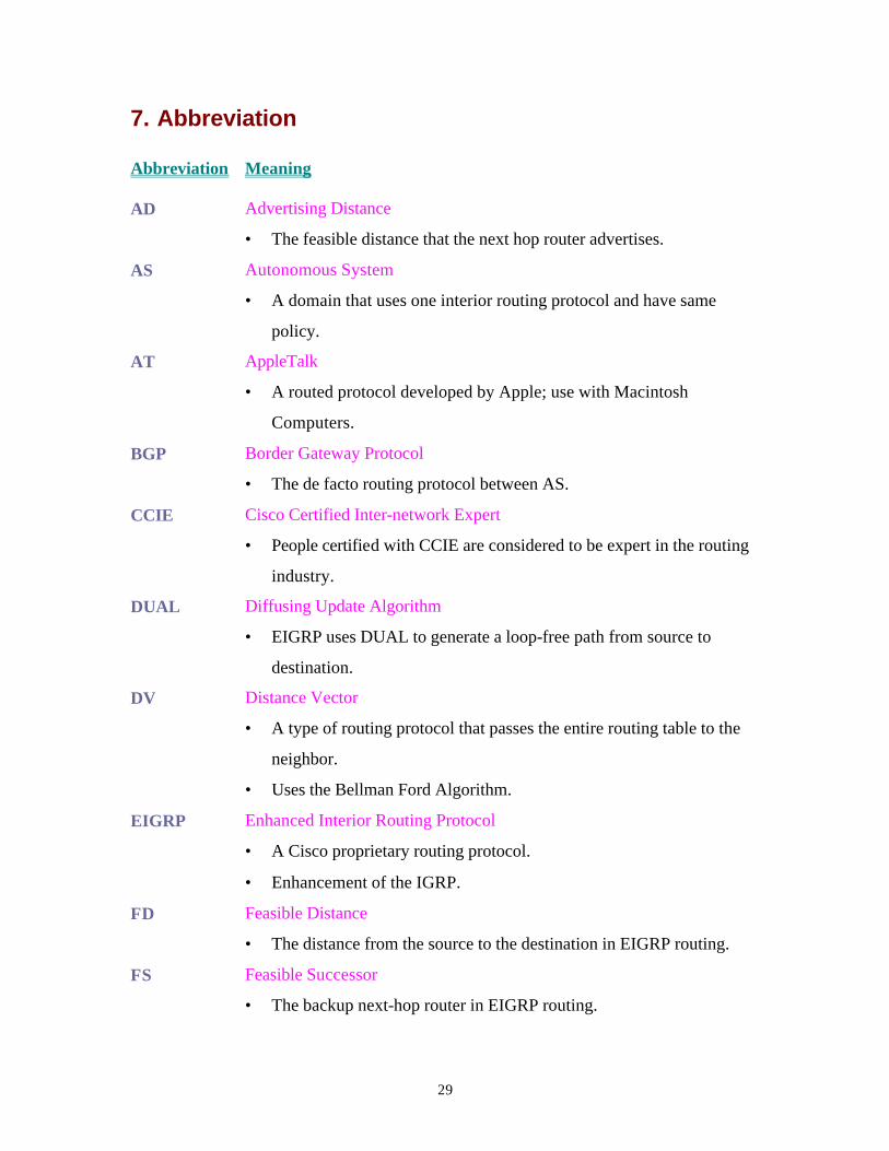
7. Abbreviation
Abbreviation Meaning
AD Advertising Distance
• The feasible distance that the next hop router advertises.
AS Autonomous System
• A domain that uses one interior routing protocol and have same
policy.
AT AppleTalk
• A routed protocol developed by Apple; use with Macintosh
Computers.
BGP Border Gateway Protocol
• The de facto routing protocol between AS.
CCIE Cisco Certified Inter-network Expert
• People certified with CCIE are considered to be expert in the routing
industry.
DUAL Diffusing Update Algorithm
• EIGRP uses DUAL to generate a loop-free path from source to
destination.
DV Distance Vector
• A type of routing protocol that passes the entire routing table to the
neighbor.
• Uses the Bellman Ford Algorithm.
EIGRP Enhanced Interior Routing Protocol
• A Cisco proprietary routing protocol.
• Enhancement of the IGRP.
FD Feasible Distance
• The distance from the source to the destination in EIGRP routing.
FS Feasible Successor
• The backup next-hop router in EIGRP routing.
30
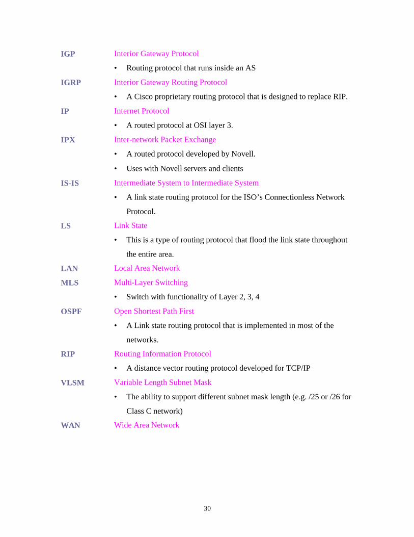
IGP Interior Gateway Protocol
• Routing protocol that runs inside an AS
IGRP Interior Gateway Routing Protocol
• A Cisco proprietary routing protocol that is designed to replace RIP.
IP Internet Protocol
• A routed protocol at OSI layer 3.
IPX Inter-network Packet Exchange
• A routed protocol developed by Novell.
• Uses with Novell servers and clients
IS-IS Intermediate System to Intermediate System
• A link state routing protocol for the ISO’s Connectionless Network
Protocol.
LS Link State
• This is a type of routing protocol that flood the link state throughout
the entire area.
LAN Local Area Network
MLS Multi-Layer Switching
• Switch with functionality of Layer 2, 3, 4
OSPF Open Shortest Path First
• A Link state routing protocol that is implemented in most of the
networks.
RIP Routing Information Protocol
• A distance vector routing protocol developed for TCP/IP
VLSM Variable Length Subnet Mask
• The ability to support different subnet mask length (e.g. /25 or /26 for
Class C network)
WAN Wide Area Network
31
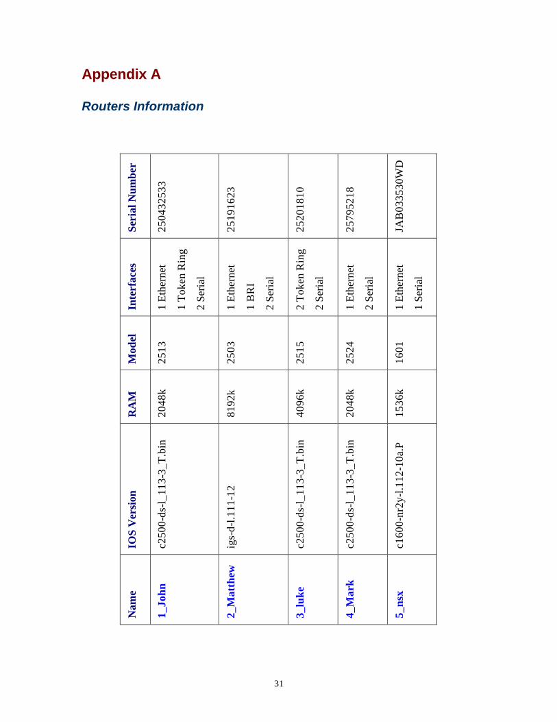
Appendix A
Routers Information
Se
rial
Num
ber
2504
3253
3
2519
1623
2520
1810
2579
5218
JAB
0335
30W
D
Inte
rfac
es
1 E
ther
net
1 T
oken
Rin
g
2 Se
rial
1 E
ther
net
1 B
RI
2 Se
rial
2 T
oken
Rin
g
2 Se
rial
1 E
ther
net
2 Se
rial
1 E
ther
net
1 Se
rial
Mod
el
2513
2503
2515
2524
1601
RA
M
2048
k
8192
k
4096
k
2048
k
1536
k
IOS
Ver
sion
c250
0-ds
-l_1
13-3
_T.b
in
igs-
d-l.1
11-1
2
c250
0-ds
-l_1
13-3
_T.b
in
c250
0-ds
-l_1
13-3
_T.b
in
c160
0-nr
2y-l
.112
-10a
.P
Nam
e
1_Jo
hn
2_M
atth
ew
3_lu
ke
4_M
ark
5_ns
x
32
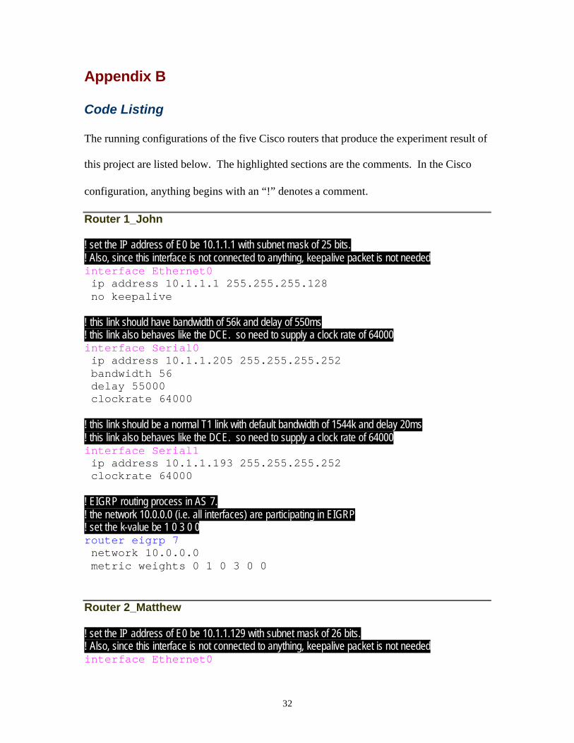
Appendix B
Code Listing
The running configurations of the five Cisco routers that produce the experiment result of
this project are listed below. The highlighted sections are the comments. In the Cisco
configuration, anything begins with an “!” denotes a comment.
Router 1_John
! set the IP address of E0 be 10.1.1.1 with subnet mask of 25 bits. ! Also, since this interface is not connected to anything, keepalive packet is not needed interface Ethernet0 ip address 10.1.1.1 255.255.255.128 no keepalive ! this link should have bandwidth of 56k and delay of 550ms ! this link also behaves like the DCE. so need to supply a clock rate of 64000 interface Serial0 ip address 10.1.1.205 255.255.255.252 bandwidth 56 delay 55000 clockrate 64000 ! this link should be a normal T1 link with default bandwidth of 1544k and delay 20ms ! this link also behaves like the DCE. so need to supply a clock rate of 64000 interface Serial1 ip address 10.1.1.193 255.255.255.252 clockrate 64000 ! EIGRP routing process in AS 7. ! the network 10.0.0.0 (i.e. all interfaces) are participating in EIGRP ! set the k-value be 1 0 3 0 0 router eigrp 7 network 10.0.0.0 metric weights 0 1 0 3 0 0
Router 2_Matthew
! set the IP address of E0 be 10.1.1.129 with subnet mask of 26 bits. ! Also, since this interface is not connected to anything, keepalive packet is not needed interface Ethernet0
33
ip address 10.1.1.129 255.255.255.192 no keepalive ! this link should have bandwidth of 56k and delay of 550ms interface Serial0 ip address 10.1.1.209 255.255.255.252 bandwidth 56 delay 55000 ! this link should be a normal T1 link with default bandwidth of 1544k and delay 20ms interface Serial1 ip address 10.1.1.202 255.255.255.252 ! EIGRP routing process in AS 7. ! the network 10.0.0.0 (i.e. all interfaces) are participating in EIGRP ! set the k-value be 1 0 3 0 0 router eigrp 7 network 10.0.0.0 metric weights 0 1 0 3 0 0
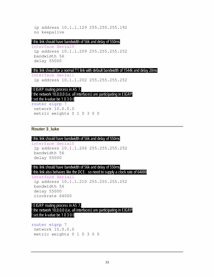
Router 3_luke
! this link should have bandwidth of 56k and delay of 550ms interface Serial0 ip address 10.1.1.206 255.255.255.252 bandwidth 56 delay 55000 ! this link should have bandwidth of 56k and delay of 550ms ! this link also behaves like the DCE. so need to supply a clock rate of 64000 interface Serial1 ip address 10.1.1.210 255.255.255.252 bandwidth 56 delay 55000 clockrate 64000 ! EIGRP routing process in AS 7. ! the network 10.0.0.0 (i.e. all interfaces) are participating in EIGRP ! set the k-value be 1 0 3 0 0 router eigrp 7 network 10.0.0.0 metric weights 0 1 0 3 0 0
34
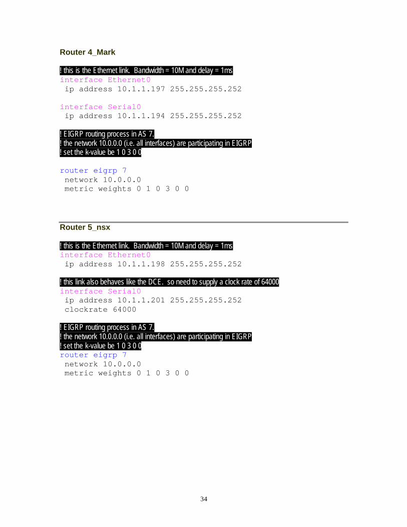
Router 4_Mark
! this is the Ethernet link. Bandwidth = 10M and delay = 1ms interface Ethernet0 ip address 10.1.1.197 255.255.255.252 interface Serial0 ip address 10.1.1.194 255.255.255.252 ! EIGRP routing process in AS 7. ! the network 10.0.0.0 (i.e. all interfaces) are participating in EIGRP ! set the k-value be 1 0 3 0 0 router eigrp 7 network 10.0.0.0 metric weights 0 1 0 3 0 0
Router 5_nsx
! this is the Ethernet link. Bandwidth = 10M and delay = 1ms interface Ethernet0 ip address 10.1.1.198 255.255.255.252 ! this link also behaves like the DCE. so need to supply a clock rate of 64000 interface Serial0 ip address 10.1.1.201 255.255.255.252 clockrate 64000 ! EIGRP routing process in AS 7. ! the network 10.0.0.0 (i.e. all interfaces) are participating in EIGRP ! set the k-value be 1 0 3 0 0 router eigrp 7 network 10.0.0.0 metric weights 0 1 0 3 0 0