Embed Size (px)
Citation preview

Convection Heated Holding Cabinets
1
P/N 780085 1/06
OPERATION & MAINTENANCE MANUAL
Phone: +1Fax: +1 (214) 565-0976Toll Free: +1 (800) 441-1601Website: www.BevLes.comE-mail: [email protected]
(214) 421-7366
BevLes729 Third AvenueDallas, TX 75226
Innovative Foodservice Equipment CustomDesigned for Performance, Service and Value.
CA34-CV9CA43-CV7 or CV13
CA70-CV16 or CV32
CA34-CVMP4CA43-CVMP6
CA70-CVMP12
CS34-CH9CS43-CH7 or CH13
CS72-CH16 or CH32
CS34-CHUS4CS43-CHUS6
CS70-CHUS15
CS43-CVMP6-SBCS61-CVMP12-SBCS71-CVMP15-SB
MODELS:

WARRANTY
GETTING STARTED
OPERATION
CARE OF YOUR UNIT
TROUBLESHOOTING
MAINTENANCE
REPLACEMENT PARTS
WIRING DIAGRAMS
3
4
INTRODUCTION 4
MODELS 4
UNPACKING 4
SETTING-UP 5
CLEANING. 5
6
OPERATING CONTROLS AND COMPONENTS 6
OPERATIONAL PROCEDURES 6
7
ASSISTANCE 7
SAFETY AND HEALTH 7
CLEANING 7
MODEL SPECIFICATIONS 7
7
TROUBLESHOOTING 7
TROUBLESHOOTING TABLE 8
9
REPLACING PARTS 9
REMOVING THE TOP MOUNTED HEATING MODULE 9
REMOVING THE FRONT PANEL 9
POWER INDICATOR LAMP MODULE 9
THERMOSTAT INDICATOR LAMP MODULE 10
POWER SWITCH 10
THERMOMETER 11
POWER CORD FOR CA70 11
POWER CORD FOR CA43 12
THERMOSTAT FOR CA70 13
THERMOSTAT FOR CA43 14
FAN BLOWER MOTOR ASSEMBLY 16
HEATING ELEMENT 17
HIGH-TEMPERATURE SAFETY THERMOSTAT 18
TOP MOUNTED HEATING MODULE SEAL (GASKET) 18
FAN BLOWER COOLING FAN FOR CA43 18
19
HOW TO ORDER 19
PRICES 19
SHIPPING 19
WARRANTY 19
PARTS DRAWINGS 19
PARTS LISTS w/EXPLODED VIEWS 20
29
CA70 MODELS 29
CA43 MODELS 29
1
2
3
4
5
6
7
8
2-1
2-2
2-3
2-4
2-5
3-1
3-2
4-1
4-2
4-3
4-4
5-1
5-2
6-1
6-1a
6-1b
6-1c
6-1d
6-1e
6-1f
6-1g
6-1h
6-1i
6-1j
6-1k
6-1l
6-1m
6-1n
6-1o
7-1
7-2
7-3
7-4
7-5
7-6
8-1a
8-1b
TABLE OF CONTENTS
2

4/02
BEVLES COMPANY LIMITED WARRANTY729 Third Avenue * Dallas, TX 75226
Phone: +1 (214) 421-7366 Fax: +1 (214) 565-0976
1. Bevles warrants to the original purchaser that on the date the equipment is shipped (sold), it will befree of defects in materials or workmanship. Bevles will, at it�s discretion, repair or replace, duringthe warranty period printed below, any part that has a defect in material or workmanship that waspresent when the product shipped from Bevles, and which manifests itself during the warrantyperiodundernormaluse and service.
Parts:Two*years fromdateof original shipment from theBevles factory.Labor:One**year
* Air CirculationBlowerAssemblies (motors) and Power Switches shall be one year from dateof original shipment.
Calrod�Air�HeatingElements shall be threeyears fromdateof original shipment.
** All electrical components120days
2. Bevles must be contacted, and pre-approval must be issued by the Bevles factory prior to any typeof servicebeingperformed.Bevles assumesno responsibility for any charges thatwere not expresslyauthorizedby theBevles factory, or for anycharges that exceed, inBevles�solejudgement, normaland customaryamounts.
3. Bevles will pay UPS Ground charges for any part that has a defect in material or workmanship thatwas present when the product shipped fromBevles, and whichmanifests itself during theof thewarranty period under normal use and service.All warranty replacementpartswill ship F.O.B.Bevles factory,Cheyenne,WY82003.
4. This warranty shall be void in its entirety if any abuse of, misuse of, alteration/modification of orimproper maintenance of original product occurs. If, at any time a claim is reported to Bevles, thepurchaser is delinquent in payment for theproduct,warrantywill not apply.
5. Buyer�s Remedies-If a Bevles product fails due to a defect inmaterial orworkmanship in conformitywith the warranties in paragraph one, buyer shall notify Bevles of such failure within a reasonabletime, but in no event beyond fifteen (15) days of such discovery of defect in material orworkmanship. Bevles shall provide, in its sole discretion, either the repair or replacement of anydefective or any non-conforming part. Bevles specifically disavows any other representation,warrantyor liability relating to the continueduseof theproduct.
6 Exclusion of consequential and incidental damages-In no event shall Bevles be liable for anyincidental, special, indirect, or consequential damages,whether resulting from non-deliveryor fromthe use, misuse, or inability to use the product, or from defects in the product, or fromBevles�own negligence or other tort. This exclusion applies regardless of whether such damages aresought for breach of warranty, breach of contract, negligence, or strict liability in tort or under anyother legal theory.
7. Disclaimer of warranties-The warranties contained in paragraph one above are the exclusivewarranties given by Bevles and supersede any prior, contrary, or additional representations,whether oral or written. Bevles hereby disclaims and excludes all other warranties-whetherexpressed, implied, or statutory-including any warranty of merchantability, any warranty offitness for a particular purpose, and any implied warranties otherwise arising from course ofdealingor usageof trade.
!
! fromdateof original shipment from theBevles factory.
fromdateof original shipment.
first year
1/05
3
1. WARRANTY

2. GETTING STARTED
2-1 INTRODUCTION
**NOTE: "NOTE""WARNING”
2-2 MODELS
2-3 UNPACKING
**NOTE:
WARNING:
NOTE:
BEVLES Heated Holding Cabinets are quality built equipment designed to hold prepared foods at a safetemperature (no less than 140°), with or without humidity. These cabinets have a wide range of applications forboth institutional and commercial foodservice operations
This manual has been prepared so that all personnel responsible for the operation and maintenance of thisequipment will have a thorough understanding of its operation and use. We recommend that any personnelusing the cabinet read this manual thoroughly before operating the equipment.
Certain items of information and procedures will be highlighted with the words or. Please make special note of these items as they will communicate important
information for the safety of your personnel, and the continued quality of service provided by theequipment.
All BEVLES Heated Holding Cabinets are designed to hold hot products at the desired holding temperature.They accomplish this through patented air and humidity systems that force heated, moist air laterally acrosseach level of the cabinet from side mounted air-flow ducts. Each cabinet also offers certain features that makethem extremely easy to use, clean and service:
The easily removable top mounted heating module contains all of the cabinet's electrical components.
Dutch doors are mounted on the front with a full-length door on the back (for 70 inch models). All doorsare removable and equipped with patented positive extruded latches.
Standard models offer right-hand swing doors, but all cabinet doors can be hinged either left or right.
Heavy-duty ball bearing casters provide easy and reliable mobility (for 70 inch and 43 inch models).
CA70-CV16 CA 70-CV16HW CA 70-CV32 CA 70-CV32HW CA70-CVMP12CA70-CVMP15 CA43-CV7 CA43-CV7HW CA43-CV13 CA43-CV13HWCA43-CVMP6 CA43-CVMP7
All BEVLES cabinets are tested, inspected and expertly packed to insure arrival in a ready-to-usecondition. If damage or loss is discovered when unpacking, ask the carrier's agent (in writing) to inspect thegoods. This should be done within 15 days of delivery. You can then file a formal claim with the carrier. If we canhelp in any way, please call us.
This product has been shipped on a wooden base, packed with secure padding and covered with a plastic bagand corrugated shipping container.
1. Carefully cut the metal banding.2. Lift the shipping container off of the unit.3. Lift the unit off of the wooden base. Use extreme care in lifting to prevent personal injury.4. Remove the plastic bag and properly dispose of it.5. Check model number on the serial number label (located on the top right front corner of the right
side of the unit) against the packing slip.6. Open doors and remove packing materials.7. Before using, the cabinet should be thoroughly cleaned as instructed in section 2-5 of this
manual.
�
�
�
�
This manual applies to the following models:
To open:
4

2-4 SETTING-UP
**WARNING:
Locate your holding cabinet in an area where the doors can be opened without impeding your operation andwhere loading and unloading product will be easy.
A clearance of at least four (4) inches is required between the top of full size units (modelsbeginning with CA70) and any other equipment or surfaces to allow air to circulate to the motor air vents. Do notset anything on top of these units.
Proper operation of the unit requires that it be level and that it be plugged into a separate electrical lineprotected by a fuse or circuit breaker of the proper rating.
CA70-CV16 120V/1500W/14.3A CA43-CV7 120V/1500W/14.3ACA70-CV16HW 120V/2000W/18.5A CA43-CV7HW 120V/2000W/17.0ACA70-CV32 120V/1500W/14.3A CA43-CV13 120V/1500W/14.3ACA70-CV32HW 120V/2000W/18.5A CA43-CV13HW 120V/2000W/17.0ACA70-CVMP12 120V/2000WI18.5A CA43-CVMP6 120V/2000W/17.0ACA70-CVMP15 120V/2000W/18.5A CA43-CVMP7 120V/2000W/17.0A
WARNING:
2-5 CLEANING**NOTE:
CAUTION:
**NOTE:
**NOTE:
**NOTE:
Plug your unit only .into a grounded receptacle of the correctvoltage. Check the serial number label located in the top right front corneron the right side of the cabinet to determine your unit's electrical rating.
Never use steel wool or caustic cleaning compounds on yourBEVLES holding cabinet.
1. Push power switch to the OFF position.2. Unplug power cord from wall.
Always unplug the unit before dismantling or cleaning.3. Remove front and back doors by lifting entire door and sliding
hinge off of hinge pins. 1)Avoid motions other than straight up or down when
removing and replacing doors so as not to damage hinges.4. Slide out stainless steel water pan containing the three "U"
shaped baffles.5. Lift off the heating module from the top of the cabinet.
At least two people should do the lifting to avoidpossible injury.
6. Remove all trays.7. Remove tray supports by carefully lifting each panel and tilting
the bottom toward the center of the cabinet. 3)Handle the support panels carefully as any damage or
bending will make reinstallation very difficult8. Remove positive door latches 4):
8a. Firmly hold the latch plateagainst the edge of the door andpull the black capped pin up andout.
8b. Slowly pull the latch plate awayfrom the door, ready to catch theflat metal spring as it releases.
9. Models equipped with dutchdoors will also have a removablewiper blade attached to the top ofthe bottom door. To remove this,loosen the two black knurledknobs at either end of the wiperblade retainer. Lift off thestainless steel retainer and thewiper blade.
Cleaning Steps:
(Fig.
(Fig.2)
(Fig.
(Fig.
Figure 1
Figure 2
Figure 3 Figure 4
5
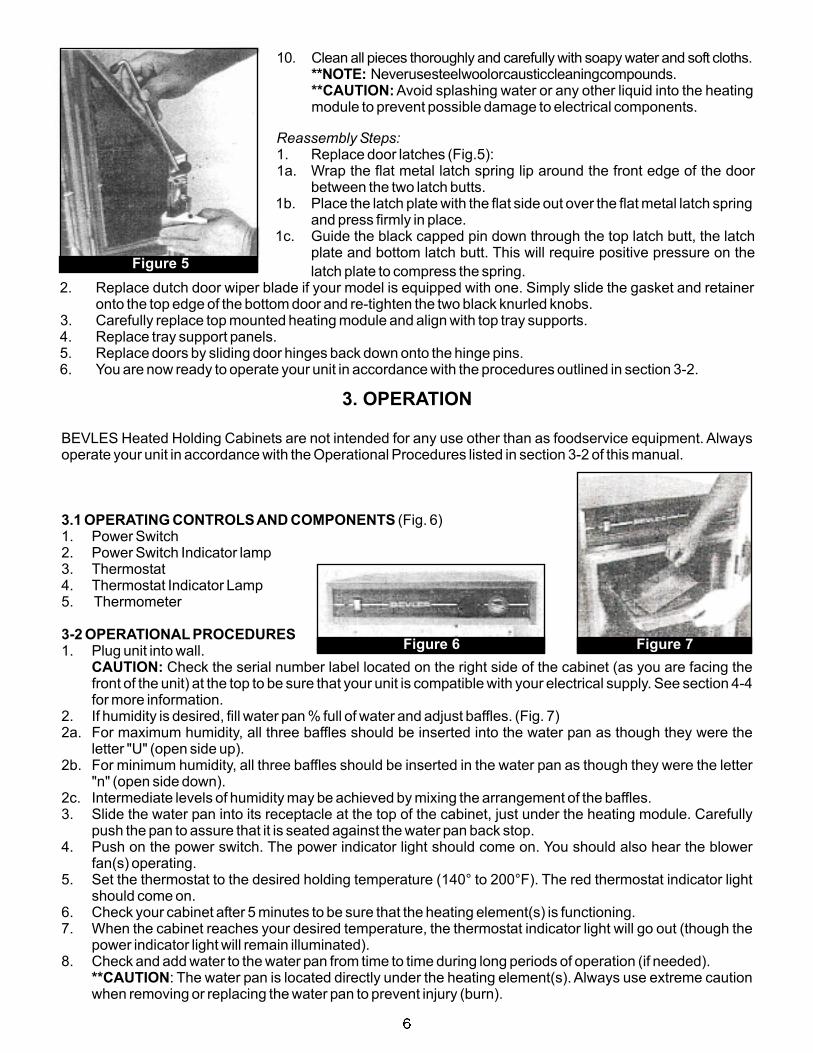
Figure 5
10. Clean all pieces thoroughly and carefully with soapy water and soft cloths.Neverusesteelwoolorcausticcleaningcompounds.
Avoid splashing water or any other liquid into the heatingmodule to prevent possible damage to electrical components.
**NOTE:**CAUTION:
Reassembly Steps:1. Replace door latches ):1a. Wrap the flat metal latch spring lip around the front edge of the door
between the two latch butts.1b. Place the latch plate with the flat side out over the flat metal latch spring
and press firmly in place.1c. Guide the black capped pin down through the top latch butt, the latch
plate and bottom latch butt. This will require positive pressure on the
(Fig.5
latch plate to compress the spring.2. Replace dutch door wiper blade if your model is equipped with one. Simply slide the gasket and retainer
onto the top edge of the bottom door and re-tighten the two black knurled knobs.3. Carefully replace top mounted heating module and align with top tray supports.4. Replace tray support panels.5. Replace doors by sliding door hinges back down onto the hinge pins.6. You are now ready to operate your unit in accordance with the procedures outlined in section 3-2.
3. OPERATION
BEVLES Heated Holding Cabinets are not intended for any use other than as foodservice equipment. Alwaysoperate your unit in accordance with the Operational Procedures listed in section 3-2 of this manual.
1. Power Switch2. Power Switch Indicator lamp3. Thermostat4. Thermostat Indicator Lamp5. Thermometer
1. Plug unit into wall.Check the serial number label located on the right side of the cabinet (as you are facing the
front of the unit) at the top to be sure that your unit is compatible with your electrical supply. See section 4-4for more information.
2. If humidity is desired, fill water pan % full of water and adjust baffles.2a. For maximum humidity, all three baffles should be inserted into the water pan as though they were the
letter "U" (open side up).2b. For minimum humidity, all three baffles should be inserted in the water pan as though they were the letter
"n" (open side down).2c. Intermediate levels of humidity may be achieved by mixing the arrangement of the baffles.3. Slide the water pan into its receptacle at the top of the cabinet, just under the heating module. Carefully
push the pan to assure that it is seated against the water pan back stop.4. Push on the power switch. The power indicator light should come on. You should also hear the blower
fan(s) operating.5. Set the thermostat to the desired holding temperature (140° to 200°F). The red thermostat indicator light
should come on.6. Check your cabinet after 5 minutes to be sure that the heating element(s) is functioning.7. When the cabinet reaches your desired temperature, the thermostat indicator light will go out (though the
power indicator light will remain illuminated).8. Check and add water to the water pan from time to time during long periods of operation (if needed).
: The water pan is located directly under the heating element(s). Always use extreme cautionwhen removing or replacing the water pan to prevent injury (burn).
3.1 OPERATING CONTROLSAND COMPONENTS
3-2 OPERATIONAL PROCEDURES
CAUTION:
**CAUTION
(Fig. 6)
(Fig. 7)
Figure 6 Figure 7
6

4. CARE OF YOUR UNIT
As with any piece of quality equipment, your BEVLES Heated Holding Cabinet requires regular care andmaintenance. The most vital procedure is the regular and thorough cleaning of the entire unit.
For your assistance, we have included the following sections in this manual:2-4 Setting Up 5 Troubleshooting 7-6 Parts List2-5 Cleaning 6-1 Replacing Parts 8-1 Wiring Diagrams
BEVLES is proud of each quality-built cabinet. Should you ever need assistance, parts or additional equipmentjust call the BEVLES Manufacturing Facilities at (800) 441-1601.
In addition, refer to the Troubleshooting (5) and Replacement Steps (6-1) sections of this manual for assistanceif occasional maintenance questions should arise.
BEVLES Heated Holding Cabinets carry both ULand NSF listings.Always operate your unit in accordance withthe operational procedures found in section 3-2.
Never remove the top mounted heating module without first unplugging your cabinet from itspower source.
Refer to section 2-5 for complete cleaning steps and procedures.
4-1ASSISTANCE
4-2 SAFETYAND HEALTH
**CAUTION:
4-3 CLEANING
CA 70-CV16 3 1/4" 16 70'' 24 ½” 31" 1500 120/240 14.3/7.2CA70-CV16HW* 3 1/4” 16 70" 24 ½” 31" 2000 120/240 18.5/9.3CA 70-CV32 1 1/2" 32 70" 24 ½” 31" 1500 120/240 14.3/7.2CA 70-CV32HW* 1 1/2” 32 70'' 24 ½” 31" 2000 120/240 18.5/9.3CA70-CVMP12* 4" 12 24 70" 29 31" 2000 120/240 18.5/9.3CA70-CVMP15* 3 1/4" 15 30 70'' 29 31" 2000 120/240 18.5/9.3
CA43-CV7 3 1/4" 7 42" 24 ½” 31" 1500 120/240 14.3/7.2
CA43-CV7HW* 3 1/4” 7 42” 24 ½” 31" 2000 120/240 17.0/8.5CA43-CV13 1 1/2" 13 42” 24 ½” 31" 1500 120/240 14.3/7.2CA43-CV13HW* 1 1/2” 13 42” 24 ½” 31" 2000 120/240 17.0/8.5CA43-CVMP6* 4" 6 12 42” 29” 31" 2000 120/240 17.0/8.5CA43-CVMP7* 3 1/4" 7 14 42” 29” 31” 2000 120/240 17.0/8.5
A
Model Vertical PanSpacing
Capacity(18” x 26” Pans)
Capacity(12” x 20” Pans)
DimensionsHeight Width Depth
ElectricalWatts Volts Amps
4-4 MODEL SPECIFICATIONS
*Units furnished with 20 AMP plug and cord, NEMA #5-20R
5. TROUBLESHOOTING
If you find that your unit is failing to operate properly refer first to the Operational Procedures in section 3-2 ofthis manual. Then, if necessary, use the Troubleshooting guide in section 5 to determine the cause of theproblem.
All maintenance on BEVLES Heating Holding Cabinets should be performed by trainedpersonnel using only quality BEVLES parts.
To determine the cause of any malfunction:1. Determine the problem (e.g., the food isn't staying hot).2. Locate the problem in the Troubleshooting table.3. Read through the possible causes ,then try each solution listed until the problem is resolved.
**CAUTION:
5-1 TROUBLESHOOTING
7

4. If you are unable to locate the problem in the table or if the solutions listed don't work, please call theBEVLES manufacturing facilities for assistance at (800) 441-1601. You will need to provide thefactory personnel with the following information:1. The product model and serial numbers.2. The specific nature of the problem.
In some cases it will be beneficial to also have the actual operator of the equipment available to answerquestions.
1. Unit will not heat.
2. Unit not reachingor holding desiredTemperature uniformly.
3. Unit overheating.
4. Fan blowers notoperating.
5. Cabinet steamy andtoo humid.
6. Cabinet too dry.
Power switch not in on position.
Loose or unplugged power cord.
Thermostat on wrong setting.
Faulty thermostat (not switching heatingelement on when below set temperature).Faulty internal wiring.
Faulty heating element (not getting hot).
Hi-temperature safety thermostat on.
Doors left open or ajar.
Thermostat on wrong setting.
Faulty thermostat (not switching heatingelement on when below set temperature).Faulty internal wiring.
Top mounted heating module seal(gasket) torn or worn.Faulty heater fan blower (no aircirculating).Faulty thermostat (not switching heatingelement off when above set temperature).Power switch not in on position.
Loose or unplugged power cord.
Faulty heater fan blower.
Faulty internal wiring.
Too much humidity in air flow.Holding temperature not high enough.
Holding product too long in cabinet.Water pan dry.Not enough humidity in air flow.Holding temperature too high.
Place the power switch in the ONposition.Plug power cord into properelectrical outlet.Set thermostat to correcttemperature.Replace thermostat per section 6-1i or j.Check connections for heatingmodule components persections 6-11.Replace heating element persection 6-11.Check for failure of heating elementand/or thermostat not shuttingdown.Close doors firmly and keep closedexcept. when loading or unloadingproduct.Set thermostat to correcttemperature.Replace thermostat per section6-1i or j.Check connections for heatingmodule components per section 6-11Replace gasket per section 6-1 m.
Replace fan blower motor persection 6-1k.Replace thermostat per section 6-1ior j.Place the power switch in the onposition.Plug power cord into properelectrical outlet.Replace fan blower motor persection 6-1k.Check connections for heatingmodule components per sections6-11.Adjust baffles per section 3-2.Adjust thermostat to a highertemperature level.Minimize holding time.Fill 3/4 full with water.Adjust baffles per section 3-2.Adjust thermostat to a lowertemperature (never below 140°F).
5-2 TROUBLESHOOTING TABLE
Problem Possible Cause Solution
8
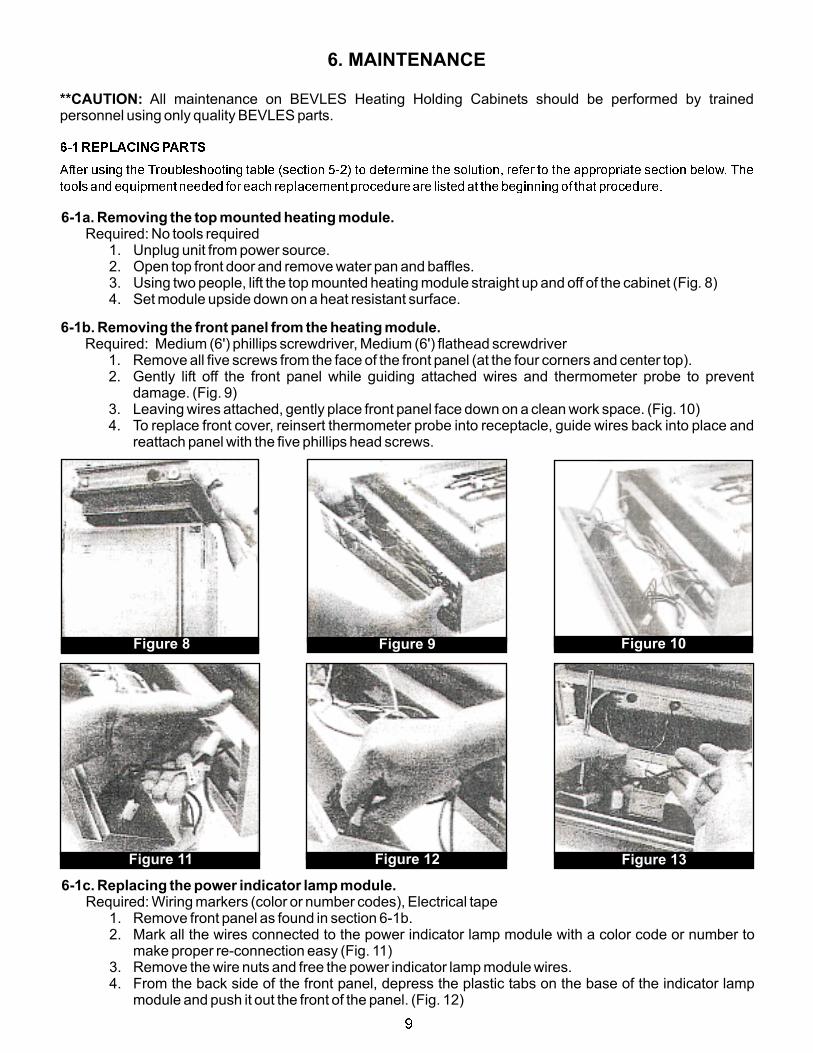
Figure 8 Figure 9 Figure 10
6. MAINTENANCE
**CAUTION: All maintenance on BEVLES Heating Holding Cabinets should be performed by trainedpersonnel using only quality BEVLES parts.
6-1REPLACINGPARTS
After using the Troubleshooting table (section 5-2) to determine the solution, refer to the appropriate section below. The
toolsandequipmentneeded for each repIacementprocedureare listedat thebeginningof that procedure.
6-1a. Removing the top mounted heating module.Required: No tools required
1. Unplug unit from power source.2. Open top front door and remove water pan and baffles.3. Using two people, lift the top mounted heating module straight up and off of the cabinet (Fig 8)4. Set module upside down on a heat resistant surface.
.
6-1b. Removing the front panel from the heating module.Required: Medium (6') phillips screwdriver, Medium (6') flathead screwdriver
1. Remove all five screws from the face of the front panel (at the four corners and center top).2. Gently lift off the front panel while guiding attached wires and thermometer probe to prevent
damage. (Fig. 9)3. Leaving wires attached, gently place front panel face down on a clean work space. (Fig. 10)4. To replace front cover, reinsert thermometer probe into receptacle, guide wires back into place and
reattach panel with the five phillips head screws.
Figure 11 Figure 12 Figure 13
6-1c. Replacing the power indicator lamp module.Required: Wiring markers (color or number codes), Electrical tape
1. Remove front panel as found in section 6-1b.2. Mark all the wires connected to the power indicator lamp module with a color code or number to
make proper re-connection easy (Fig. 11)3. Remove the wire nuts and free the power indicator lamp module wires.4. From the back side of the front panel, depress the plastic tabs on the base of the indicator lamp
module and push it out the front of the panel. (Fig. 12)
9

5. Feed the wires of the replacement indicator lamp module through the opening and snap the newindicator lamp module into place.
6. Reconnect wiring with each of the two new wires going to a different wire nut (it doesn't matter howyou match the new module wires). Re-tape over wire nuts and wires.** Be sure to correctly match the other wires that were connected at the two wire nuts.
7. Replace the front panel (section 6-1b).
Required: Medium (6") flathead screwdriver, Medium (6”) phillips screwdriver, Wiring markers (color ornumber codes), Electrical tape
1. Remove front panel as found in section 6-1 b.2. Mark all the wires connected to the thermostat indicator lamp module and thermostat with a color
code or number to make proper re-connection easy. (Fig. 11)3. Locate the thermostat indicator lamp module wire that connects to a wire nut and remove that wire
nut, freeing all wires. (Fig. 13)4. Remove the indicator lamp module wire from the terminal on the back of the thermostat by
removing the electrical tape and reversing the screw.5. From the back side of the front panel, depress the plastic tabs on the base of the indicator lamp
module and push it out the front of the panel. (Fig. 12)6. Feed the wires of the replacement indicator lamp module through the opening and snap the new
indicator lamp module into place.7. Reconnect wiring with one of the two new wires going to the wire nut and the other to the back of the
thermostat (it doesn't matter how you match the new module wires). Re-tape over wire nuts andwires.
Be sure to correctly match the other wires that were connected at the wire nut8. Replace the front panel (section 6-1 b).
Required: Wiring markers (color or number codes), Electrical tape, Wiring diagram for CA43 and CA70(see step 7 below)
1. Remove front panel as found in section 6-1b.2. Trace the four wires from the power switch to the wire nuts. Code all wires connected by the four
wire nuts to insure proper re-connection. (Fig. 14)3. Remove the wire nuts and free the power switch wires.4. From the back side of the front panel, depress the plastic tabs on the base of the power switch and
push it out the front of the panel. (Fig. 15)
WARNING:
6-1d. Replacing the thermostat indicator lamp module.
*'WARNING:
6-1e. Replacing the power switch.
Figure 14 Figure 15
Fan
Blower
(0)
(1)
(0) (1)
Power
Indicator Lamp
(5) (1)
Thermostat
Indicator Lamp
Power Switch
(0) (1)
(2) (3)
(0) (5)
Thermostat
Diagram 1
Power Cord
(Grd)
(2)(3)
(4) (1)
Heating
Element
(4) (5)
Klixon
Thermostat(0)
(1) Cooling
Fan
5. Feed the wires of the replacement switchthrough the opening and snap the newpower switch into place.
6. Reconnect wires using the four wire nutsand the wiring diagram. Re-tape over wirenuts and wires. (Diagram 1)
Severe damage can becaused to your unit by improperlyconnecting wiring.
7. Replace the front panel (section 6-1b).
**WARNING:
10

Figure 19
Figure 16
Figure 17
Figure 18
6.1f. Replacing the thermometer.
**NOTE:
6-1g. Replacing the power cord for a CA70 unit.
Required: Crescent or standard 3/4" wrench1. Remove front panel as found in section 6-1b.2. Use a crescent or standard 3/4" wrench to loosen the
thermometer mounting nut that holds the thermometer in placeon the back of the front panel. (Fig. 16)
3. Remove the nut, washer and retaining bracket and pullthermometer out the front of the panel.
4. Replace retaining bracket and insert new thermometer intoopening.
Align thermometer so that the 150° reading will bestraight up when the front panel is replaced and the heatingmodule is flipped over. (Fig. 17)
5. Replace and tighten washer and nut on rear of front panel. DONOT OVER TIGHTEN!
6. Replace the front panel (section 6-1b).
Required: Medium (6”) phillips screwdriver, Medium (6") flatheadscrewdriver, Wiring markers (color or number codes), Electrical tape,Wiring diagram for CA70 (see step 10)
1. Remove top mounted heating module and front panel as foundin sections 6-1a and 6-1b.
2. Mark all the wires connected to the power cord with a colorcode or number to make proper re-connection easy. (Fig.18) .
3. Turn the top mounted heating unit over so that the elbowconnector for the power cord is up. Free the green ground wireby grasping the nut with fingers or pliers (under front overhangof the heating module) and remove the screw from the exposedsurface of the module with a medium (6") phillips screwdriver.(Fig. 19).
4. Free the other two power cord wires by removing the two wirenuts that connect them.
5. Remove elbow connector that secures power cord into theheating module by grasping the nut holding the connector(under the overhang of the heating module). Rotate the nut toloosen and remove the elbow from the module. (Fig. 20)
6. Remove the two screws that secure the power cord into thecompression end of the elbow connector with a medium (6”)flathead screwdriver. Pull gently to free power cord from theelbow connector. (Fig. 21)
7. Insert new power cord into elbow connector and replacecompression screws. Tighten screws to secure power cord intoconnector.
: Replace only with a BEVLES power cordproperly rated for your unit.
8. Insert new wires through opening in the heating module andreattach elbow connector.
9. Reattach green ground wire to module.10. Reconnect power cord wires using wire nuts and wiring
diagram. Re-tape over wire nuts and wires. (Diagram 2)Severe damage can be caused to your unit by
improperly connecting wiring.11. Replace the front panel and top mounted heating module
(sections 6-1a. and 6-1 b).
**WARNING
**WARNING:
11

6-1h. Replacing the power cord for a CA43.Required: Medium (6”) phillips screwdriver, Medium (6") flatheadscrewdriver, Wiring markers (color or number codes), Electrical tape ,Wiring diagram for CA43(see step 10)
1. Remove the back panel of the module by removing the fivephillips head screws and gently lifting out the back panel. Laythe panel on a clean work surface. (Fig. 22)
Figure 20
Figure 21
Figure 22
Fan
Blower
(0)
(1)
(0) (1)
Power
Indicator Lamp
(5) (1)
Thermostat
Indicator LampPower Switch
(0) (1)
(2) (3)
(0) (5)
Thermostat
Diagram 2
Power Cord
(Grd)
(2)(3)
(4) (1)
Heating
Element
(4) (5)
Klixon
Thermostat
(0)
(1) Cooling
Fan
2. Mark all the wires connected to the power cord with a colorcode or number to make proper re-connection easy. (Fig. 23)
3. Free the green ground wire by grasping the nut with fingers orpliers (inside the back panel of module) and remove screwfrom the outside surface of the panel with a medium (6")phillips screwdriver. (Fig. 24)
4. Free the other two power cord wires by removing the two wirenuts they are attached to.
5. Remove elbow connector that secures power cord onto theback panel. While grasping the nut (on the inside surface of thepanel) and holding the connector (on the outside surface of thepanel), rotate the nut to loosen and remove the elbow from thepanel. (Fig. 25) .
6. Remove the two screws that secure the power cord into thecompression end of the elbow connector with a medium (6”)flathead screwdriver. Pull gently to free power cord from theelbow connector. (Fig. 26)
7. Insert new power cord into elbow connector and replacecompression screws. Tighten screws to secure power cordinto connector.
Replace only with a BEVLES power cordproperly rated for your unit.
8. Insert new wires through opening in back panel and reattachelbow connector.
9. Reattach green ground wire to back panel.10. Reconnect power cord wires using wire nuts and wiring
diagram. Retape over wire nuts and wires. (Diagram 3)Severe damage can be caused to your unit by
improperly connecting wires.11. Replace the back panel using the five phillips head screws.
*"WARNING:
**WARNING:
Figure 23
12
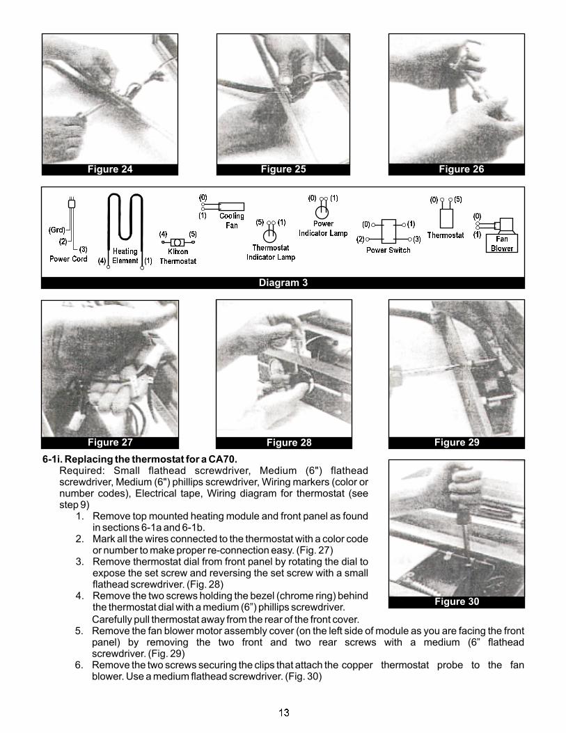
Figure 24 Figure 25 Figure 26
Fan
Blower
(0)
(1)
(0) (1)
Power
Indicator Lamp
(5) (1)
Thermostat
Indicator LampPower Switch
(0) (1)
(2) (3)
(0) (5)
Thermostat
Diagram 3
Power Cord
(Grd)
(2)(3)
(4) (1)
Heating
Element
(4) (5)
Klixon
Thermostat
(0)
(1) Cooling
Fan
Figure 27 Figure 28 Figure 29
Figure 30
6-1i. Replacing the thermostat for a CA70.Required: Small flathead screwdriver, Medium (6") flatheadscrewdriver, Medium (6") phillips screwdriver, Wiring markers (color ornumber codes), Electrical tape, Wiring diagram for thermostat (seestep 9)
1. Remove top mounted heating module and front panel as foundin sections 6-1a and 6-1b.
2. Mark all the wires connected to the thermostat with a color codeor number to make proper re-connection easy. (Fig. 27)
3. Remove thermostat dial from front panel by rotating the dial toexpose the set screw and reversing the set screw with a smallflathead screwdriver. (Fig. 28)
4. Remove the two screws holding the bezel (chrome ring) behindthe thermostat dial with a medium (6”) phillips screwdriver.
Carefully pull thermostat away from the rear of the front cover.5. Remove the fan blower motor assembly cover (on the left side of module as you are facing the front
panel) by removing the two front and two rear screws with a medium (6” flatheadscrewdriver. (Fig. 29)
6. Remove the two screws securing the clips that attach the copper thermostat probe to the fanblower. Use a medium flathead screwdriver. (Fig. 30)
13

Figure 31
Figure 32
7. Pull the copper thermostat probe and tubing from the fan blowermotor assembly area through the opening to the front cover (itmay be necessary to feed the probe, into the bottom of theassembly area under the fan blower to achieve the correctangle). (Fig. 31)
DO NOT bend or kink the copper tubing when replacingthe thermostat probe.
8. Disconnect wires from rear of thermostat by reversing screwterminals with a flathead screwdriver.
9. Connect wires to the rear of a new thermostat unit using thethermostat wiring diagram for CA70 units. Re-tape over wire nutsand wires. (Diagram 4)
10. Attach new thermostat to rear of front panel and bezel to the frontof panel with the two phillips screws.
The tops of the terminals should face down (toward theactual top of the heating module). (Fig. 32)
11. Carefully guide new copper probe and tubing through theopening to fan blower motor housing and reattach probe clipswith two flathead screws. (Fig. 31)
DO NOT kink or bend the copper probe or tubing.12. Replace fan blower motor assembly cover with two front and two
rear flathead screws. Do not over tighten.13. Replace thermostat dial, tightening set screw securely.14. Replace top mounted heating module and front panel (sections
6-1a and 6-1 b).
**NOTE:
**NOTE:
**NOTE:
Fan
Blower
(0)
(1)
(0) (1)
Power
Indicator Lamp
(5) (1)
Thermostat
Indicator LampPower Switch
(0) (1)
(2) (3)
(0) (5)
Thermostat
Diagram 4
Power Cord
(Grd)
(2)(3)
(4) (1)
Heating
Element
(4) (5)
Klixon
Thermostat
(0)
(1) Cooling
Fan
6-1j Replacing the thermostat forCA43 units.
Required: Small flathead screwdriver,Medium (6”) flathead screwdriver,Medium (6”) phillips screwdriver,Wiring markers (color or numbercodes), Electrical tape, Wiring diagramfor thermostat (see step 11)
1. Remove top mounted heatingmodule and front panel asfound in sections 6-1a and 6-1b.
2. Mark all the wires connected tothe power cord with a colorcode or number to make proper re-connection easy. (Fig. 33)
3. Remove thermostat dial from front panel by rotating the dial to expose the set screw and reversingthe sat screw with a small flathead screwdriver. (Fig. 34)
4. Remove the two screws holding the bezel (chrome ring) behind the thermostat dial with a medium(6”) phillips screwdriver. Carefully pull thermostat away from the rear of the front cover.
5. Remove the fan blower motor assembly cover (on the left side of module as you are facing the frontpanel) by removing the two front and two rear screws with a medium (6”) flathead screwdriver. (Fig. 35)
6. Pry off fan blower housing cover (with a flathead screwdriver, if necessary). Without disconnectingwires, set cover on a clean work area. (Fig. 36)
7. Remove four screws (two at each end) holding fan blower motor bracket in place with a mediumflathead screwdriver and gently lift bracket to expose mounting clips for the copper thermostatprobe. (Fig. 37)
Figure 33 Figure 34
14
Fan
Blower
(0)
(1)
(0) (1)
Power
Indicator Lamp(5) (1)
Thermostat
Indicator LampPower Switch
(0) (1)
(2) (3)
(0) (5)
Thermostat
Diagram 5
Power Cord
(Grd)
(2)(3)
(4) (1)
Heating
Element
(4) (5)
Klixon
Thermostat
(0)
(1) Cooling
Fan
Figure 39Figure 38Figure 37
Figure 36
Figure 35
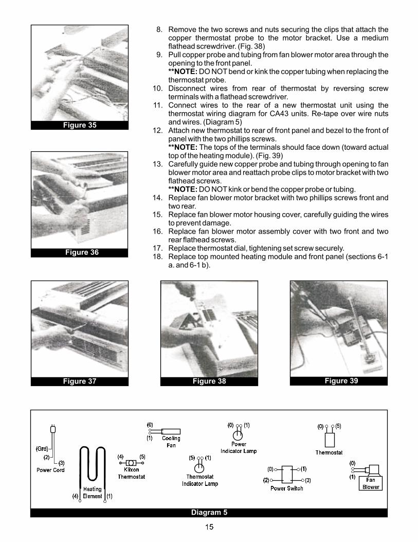
8. Remove the two screws and nuts securing the clips that attach thecopper thermostat probe to the motor bracket. Use a mediumflathead screwdriver. (Fig. 38)
9. Pull copper probe and tubing from fan blower motor area through theopening to the front panel.
DO NOT bend or kink the copper tubing when replacing thethermostat probe.
10. Disconnect wires from rear of thermostat by reversing screwterminals with a flathead screwdriver.
11. Connect wires to the rear of a new thermostat unit using thethermostat wiring diagram for CA43 units. Re-tape over wire nutsand wires. (Diagram 5)
12. Attach new thermostat to rear of front panel and bezel to the front ofpanel with the two phillips screws.
The tops of the terminals should face down (toward actualtop of the heating module). (Fig. 39)
13. Carefully guide new copper probe and tubing through opening to fanblower motor area and reattach probe clips to motor bracket with twoflathead screws.
DO NOT kink or bend the copper probe or tubing.14. Replace fan blower motor bracket with two phillips screws front and
two rear.15. Replace fan blower motor housing cover, carefully guiding the wires
to prevent damage.16. Replace fan blower motor assembly cover with two front and two
rear flathead screws.17. Replace thermostat dial, tightening set screw securely.18. Replace top mounted heating module and front panel (sections 6-1
a. and 6-1 b).
**NOTE:
**NOTE:
**NOTE:
15
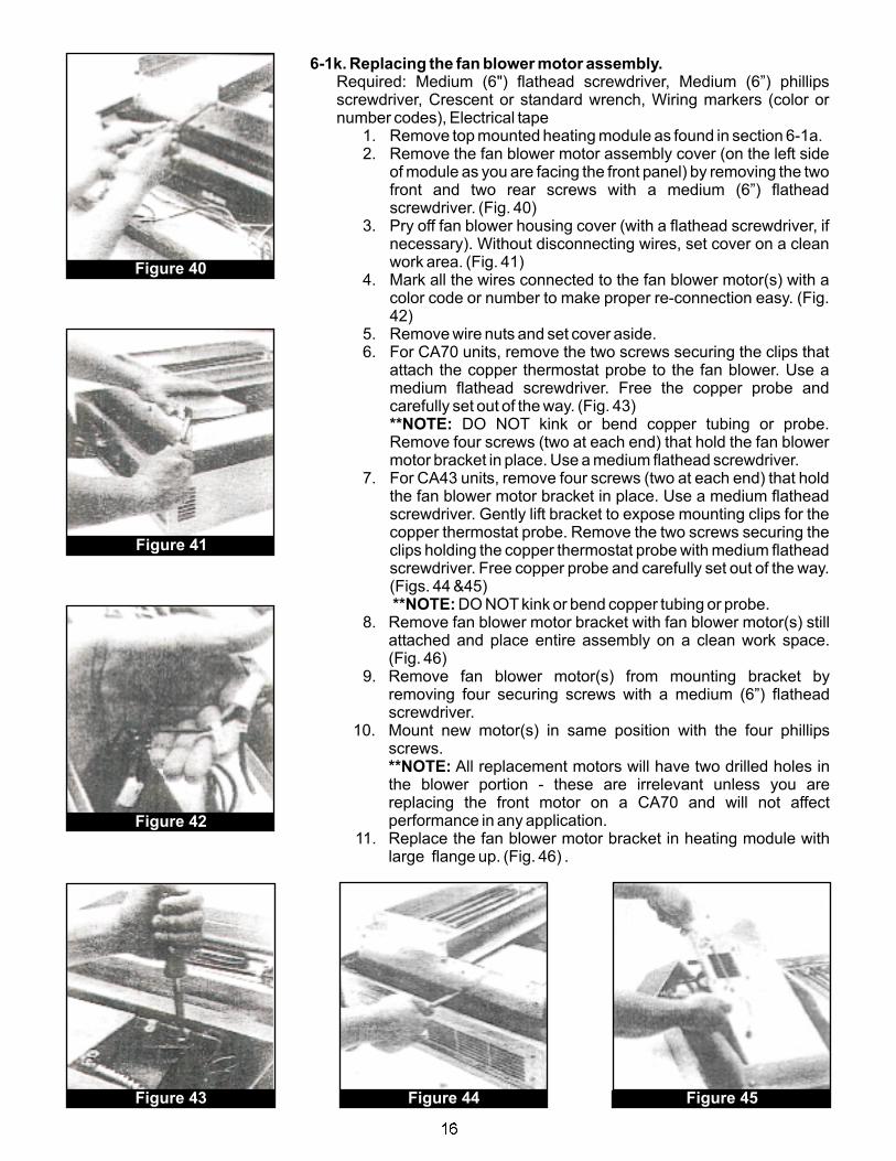
Figure 43 Figure 44 Figure 45
Figure 42
Figure 41
Figure 40
6-1k. Replacing the fan blower motor assembly.
**NOTE:
**NOTE:
**NOTE:
Required: Medium (6") flathead screwdriver, Medium (6”) phillipsscrewdriver, Crescent or standard wrench, Wiring markers (color ornumber codes), Electrical tape
1. Remove top mounted heating module as found in section 6-1a.2. Remove the fan blower motor assembly cover (on the left side
of module as you are facing the front panel) by removing the twofront and two rear screws with a medium (6”) flatheadscrewdriver. (Fig. 40)
3. Pry off fan blower housing cover (with a flathead screwdriver, ifnecessary). Without disconnecting wires, set cover on a cleanwork area. (Fig. 41)
4. Mark all the wires connected to the fan blower motor(s) with acolor code or number to make proper re-connection easy. (Fig.42)
5. Remove wire nuts and set cover aside.6. For CA70 units, remove the two screws securing the clips that
attach the copper thermostat probe to the fan blower. Use amedium flathead screwdriver. Free the copper probe andcarefully set out of the way. (Fig. 43)
DO NOT kink or bend copper tubing or probe.Remove four screws (two at each end) that hold the fan blowermotor bracket in place. Use a medium flathead screwdriver.
7. For CA43 units, remove four screws (two at each end) that holdthe fan blower motor bracket in place. Use a medium flatheadscrewdriver. Gently lift bracket to expose mounting clips for thecopper thermostat probe. Remove the two screws securing theclips holding the copper thermostat probe with medium flatheadscrewdriver. Free copper probe and carefully set out of the way.(Figs. 44 &45)
DO NOT kink or bend copper tubing or probe.8. Remove fan blower motor bracket with fan blower motor(s) still
attached and place entire assembly on a clean work space.(Fig. 46)
9. Remove fan blower motor(s) from mounting bracket byremoving four securing screws with a medium (6”) flatheadscrewdriver.
10. Mount new motor(s) in same position with the four phillipsscrews.
All replacement motors will have two drilled holes inthe blower portion - these are irrelevant unless you arereplacing the front motor on a CA70 and will not affectperformance in any application.
11. Replace the fan blower motor bracket in heating module withlarge flange up. (Fig. 46) .
16
12. For CA70 units, secure fan blower motor bracket with the fourphillips screws. Reattach thermostat probe clips with twoflathead screws.
DO NOT kink or bend the copper probe or tubing.13. For CA43 units, reattach thermostat probe clips with two
flathead screws.DO NOT kink or bend the copper probe or tubing.
Secure fan blower motor bracket with the four flathead screws.14. Reconnect existing wires to new motor wires. It is not important
which new wire is matched with which existing wire group.Re-tape over wire nuts and wires.
15. Replace fan blower motor housing cover, carefully guiding thewires to prevent damage.
16. Replace fan blower motor assembly cover with two front andtwo rear flathead screws.
17. Replace top mounted heating module (section 6-1 a).
**NOTE:
**NOTE:
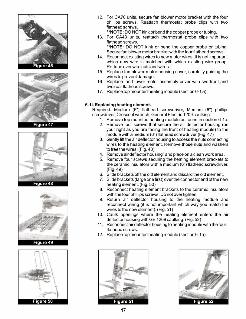
6-1l. Replacing heating element.Required: Medium (6") flathead screwdriver, Medium (6") phillipsscrewdriver, Crescent wrench, General Electric 1209 caulking
1. Remove top mounted heating module as found in section 6-1a.2. Remove four screws that secure the air deflector housing (on
your right as you are facing the front of heating module) to themodule with a medium (6”) flathead screwdriver.(Fig. 47)
3. Gently lift the air deflector housing to access the nuts connectingwires to the heating element. Remove those nuts and washersto free the wires. (Fig. 48)
4. Remove air deflector housing" and place on a clean work area.5. Remove four screws securing the heating element brackets to
the ceramic insulators with a medium (6") flathead screwdriver.(Fig. 49)
6. Slide brackets off the old element and discard the old element.7. Slide brackets (large one first) over the connector end of the new
heating element. (Fig. 50)8. Reconnect heating element brackets to the ceramic insulators
with the four phillips screws. Do not over tighten.9. Return air deflector housing to the heating module and
reconnect wiring (it is not important which way you match thewires to the new element). (Fig. 51)
10. Caulk openings where the heating element enters the airdeflector housing with GE 1209 caulking. (Fig. 52)
11. Reconnect air deflector housing to heating module with the fourflathead screws.
12. Replace top mounted heating module (section 6-1a).
Figure 46
Figure 47
Figure 48
Figure 49
Figure 50 Figure 51 Figure 52
17

6-1m. Replacing the High-temperature safety thermostat.
6-1 n. Replacing the top mounted heating module seal (gasket).
**NOTE:
6.1o. Replacing the fan blower cooling fan for CA43 units.
Required: Medium (6”) flathead screwdriver, Medium (6") phillipsscrewdriver, Crescent wrench
1. Remove top mounted heating module as found in section 6-1a.2. Remove four screws that secure the air deflector housing (on your
right as you are facing the front of heating module) to the module witha medium (6”) flathead screwdriver.
3. Gently lift the air deflector housing to access the nuts and connectingwires to the high temperature safety thermostat. Remove those nutsand washers to free the wires and the thermostat.
4. Attach the new high-temperature thermostat and reconnect the newwires.
5. Reconnect air deflector housing to heating module with the fourflathead screws.
6. Replace top mounted heating module (section 6-1 a).
Required: Razor blade, General Electric 1209 caulking1. Remove top mounted heating module as found in section 6-1a.2. Razor blade old gasket and foam tape off of the heating module. (Fig.
53)Remove all caulking and material carefully. A good seal
requires a clean surface.3. Set new gasket into place using double-face foam tape (included with
new gasket) to attach new gasket to module. (Fig. 54)4. Caulk inner and outer edges of new gasket with GE 1209 caulking.
Allow caulking to dry for at least 45 minutes. (Fig. 55)5. Replace top mounted heating module (section 6-1a).
Required: Medium (6”) flathead screwdriver, Medium (6”) phillipsscrewdriver, Wiring markers (color or number codes), Electrical tape
1. Remove the back panel of the module by removing the five flatheadscrews and gently removing the back panel. Lay the panel on a cleanwork surface.
2. Remove four screws inside the back panel that secure the cooling fanto the back panel with a medium (6”) flathead screwdriver. Savespacers for reuse. (Fig. 56)
3. Mark all the wires connected to the cooling fan with a color code ornumber to make proper re-connection easy. (Fig. 57)
4. Remove wire nuts and retain wire sleeve for reuse. Discard oldcooling fan (if under warranty and requested by BEVLES, send fanand Return MaterialAuthorization form to the factory for credit).
5. Slip reserved wire sleeve onto the wires of the new cooling fan.6. Connect new cooling fan wires to existing wires. It is not important
which way you match the new wires.7. Carefully insert nylon spacers between the cooling fan and back
panel. Connect new fan to the back panel with the four flatheadscrews. (Fig. 56)
8. Replace back panel with the five flathead screws.9. Replace top mounted heating module (section 6-1a).
Figure 53
Figure 54
Figure 55
Figure 56
Figure 57
18
7. REPLACEMENT PARTS
Use only BEVLES replacement parts in repairing your unit. This assures you of continued high qualityperformance.
To determine the parts you need:1. Use the drawings found in section 7-5 and refer to the parts list in section 7-6 to determine the
BEVLES part numbers you need.2. Note the model number, serial number and the date of manufacture of your unit from the serial
number label (located in the top right front comer of the right side of the unit).3. Call the BEVLES manufacturing facilities at (214) 421-7366 or (800) 441-1601 (outside of Texas
andAlaska).
Your distributor can provide you with a current price list for replacement parts. Or, call the BEVLESmanufacturing facilities for the most recent prices.
Common parts are in-stock for immediate processing. Normally, replacement parts will be shipped within twoworking days.
Replacement parts are fully covered by the parts provisions of the BEVLES quality assurance warranty at thefront of this manual.
Exploded drawings provided for:
CA70-CV16, CV16HW, CV32. CV32HW, CVMP12, CVMP15 7-5a. Heating Module7-5b. Cabinet Assembly
7-5c. Heating Module7-5d. Cabinet Assembly
7-1 HOW TO ORDER
7-2 PRICES
7-3 SHIPPING
7-4 WARRANTY
7-5 PARTS DRAWINGS
CA43-CV7, CV7HW, CV13,..CV13HVV, CVMP6, CVMP7
Model Number Drawing Number
19
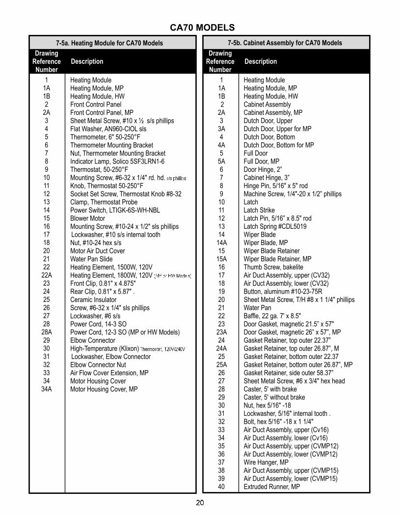
7-5a. Heating Module for CA70 Models
11A1B2
2A3456789
101112131415161718202122
22A232425262728
28A293031323334
34A
Heating ModuleHeating Module, MPHeating Module, HWFront Control PanelFront Control Panel, MPSheet Metal Screw, #10 x ½ s/s phillipsFlat Washer, AN960-ClOL slsThermometer, 6" 50-250°FThermometer Mounting BracketNut, Thermometer Mounting BracketIndicator Lamp, Solico 5SF3LRN1-6Thermostat, 50-250°FMounting Screw, #6-32 x 1/4" rd. hd.Knob, Thermostat 50-250°FSocket Set Screw, Thermostat Knob #8-32Clamp, Thermostat ProbePower Switch, LTIGK-6S-WH-NBLBlower MotorMounting Screw, #10-24 x 1/2" sls phillipsLockwasher, #10 s/s internal toothNut, #10-24 hex s/sMotor Air Duct CoverWater Pan SlideHeating Element, 1500W, 120VHeating Element, 1800W, 120VFront Clip, 0.81" x 4.875"Rear Clip, 0.81" x 5.87" .Ceramic InsulatorScrew, #6-32 x 1/4" sls phillipsLockwasher, #6 s/sPower Cord, 14-3 SOPower Cord, 12-3 SO (MP or HW Models)Elbow ConnectorHigh-Temperature (Klixon)Lockwasher, Elbow ConnectorElbow Connector NutAir Flow Cover Extension, MPMotor Housing CoverMotor Housing Cover, MP
s/s phillips
(MP or HW Models)
Thermostat, 120V/240V
DrawingReferenceNumber
Description
7-5b. Cabinet Assembly for CA70 Models
DrawingReferenceNumber
Description
11A1B2
2A3
3A4
4A5
5A6789
1011121314
14A15
15A1617181920212223
23A24
24A25
25A262728293031323334353637383940
Heating ModuleHeating Module, MPHeating Module, HWCabinet AssemblyCabinet Assembly, MPDutch Door, UpperDutch Door, Upper for MPDutch Door, BottomDutch Door, Bottom for MPFull DoorFull Door, MPDoor Hinge, 2”Cabinet Hinge, 3”Hinge Pin, 5/16" x 5" rodMachine Screw, 1/4"-20 x 1/2” phillipsLatchLatch StrikeLatch Pin, 5/16” x 8.5" rodLatch Spring #CDL5019Wiper BladeWiper Blade, MPWiper Blade RetainerWiper Blade Retainer, MPThumb Screw, bakeliteAir Duct Assembly, upper (CV32)Air Duct Assembly, lower (CV32)Button, aluminum #10-23-75RSheet Metal Screw, T/H #8 x 1 1/4" phillipsWater PanBaffle, 22 ga. 7' x 8.5"Door Gasket, magnetic 21.5” x 57"Door Gasket, magnetic 26” x 57”, MPGasket Retainer, top outer 22.37”Gasket Retainer, top outer 26.87”, MGasket Retainer, bottom outer 22.37Gasket Retainer, bottom outer 26.87”, MPGasket Retainer, side outer 58.37”Sheet Metal Screw, #6 x 3/4" hex headCaster, 5' with brakeCaster, 5' without brakeNut, hex 5/16" -18Lockwasher, 5/16" internal tooth .Bolt, hex 5/16" -18 x 1 1/4"Air Duct Assembly, upper (Cv16)Air Duct Assembly, lower (Cv16)Air Duct Assembly, upper (CVMP12)Air Duct Assembly, lower (CVMP12)Wire Hanger, MPAir Duct Assembly, upper (CVMP15)Air Duct Assembly, lower (CVMP15)Extruded Runner, MP
CA70 MODELS
20

CA43 MODELS
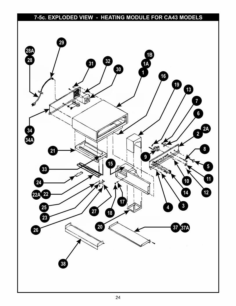
7-5c. Heating Module for CA43 Models
DrawingReferenceNumber
Description
11A1B2
2A3456789
10111213141516171819202122
22A232425262728
28A293031323334
34A353637
37A38
Heating ModuleHeating Module, MPHeating Module, HWFront Control PanelFront Control Panel, MPSheet Metal Screw, #10 x 1/2" S/S phillipsFlat Washer, AN96O-C1OL S/SThermometer, 8” 50-250°FThermometer Mounting BracketNut, Thermometer Mounting BracketIndicator Lamp, SoIico SSF3LRN1-6Thermostat, 50-250°FMounting Screw, #6-32 x 1/4" rd. hd.Knob, thermostat 50-250°FSocket Set Screw, Thermostat Knob #8-32Clamp, Thermostat ProbePower Switch, LTlGK-6S-WH-NBLBlower MotorMounting Screw, #10-24 x 1/2" s/s phillipsLockwasher, #10 S/S internal toothNut, #10-24 hex s/sMotor Air DuctMotor Air Duct CoverWater Pan SlideHeating Element, 1500W, 120VHeating Element, 1800W, 120VFront Clip, 0.81" x 4.875"Rear Clip, 0.81" x 5.87'Ceramic InsulatorScrew, #6-32 x 1/4” s/s phillipsLockwasher, #6 s/sPower Cord, 14-3 SOPower Cord, 12-3 SO (MP or HW Models)Elbow ConnectorCooling FanMachine Screw, #10-24 x 2" phillipsSpacerHigh-Temp. (Klixon) Thermostat,Rear PanelRear Panel, MPElbow Connector NutLockwasher, Elbow ConnectorMotor Housing CoverMotor Housing Cover, MPAir Flow Cover Extension, MP
s/s phillips
(MP or HW Models)
120V/240V
7-5d. Cabinet Assembly for CA43 Models
DrawingReferenceNumber
Description
11A1B2
2A3
3A5
5A678910111213171920212223
23A24
24A25
25A262728293031323334353637
Heating ModuleHeating Module, MPHeating Module, HWCabinet AssemblyCabinet Assembly, MPFront DoorFront Door for MPRear DoorRear Door, MPDoor Hinge, 2"Cabinet Hinge, 3”Hinge Pin, 5/16" x 5” rodMachine Screw, 1/4"-20 x ½” phillipsLatchLatch StrikeLatch Pin, 5/16" x 8.5" rodLatch Spring #CDL5019Air Duct Assembly (CV13)Button, aluminum #l0-23-75RSheet Metal Screw, T/H #8 x 1/4” phillipsWater PanBaffle, 22 ga 7” x 8.5”Door Gasket, magnetic 21.5” x 28.5"Door Gasket, magnetic 26” x 28.5", MPGasket Retainer, top outer 22.37"Gasket Retainer, top outer 26.87”, MPGasket Retainer, bottom outer 22.37"Gasket Retainer, bottom outer 26.87", MPGasket Retainer, side outer 29.5”Sheet Metal Screw, #6 x 3/4" hex headCaster, 5” with brakeCaster, 5” without brakeNut, hex 5/16"-18Lockwasher, 5/16” internal toothBolt, hex 5/16”-18 x 1 1/4”Air Duct Assembly (CV7)Air Duct Assembly (CVMP6)Wire Hanger, MPAir Duct Assembly (CVMP7)Extruded Runner, MP
21

7-5a. EXPLODED VIEW - HEATING MODULE FOR CA70 MODELS
28
28A29
31
32
11A
1B
17
16
13
76
2
2A
8
5
12
9
11
3
4
14
10
27 18
15
33
34 34A20
21
24
2222A
25
23
26
30
22

40
14A
24A
24
26
28
29
31 32
25A
35
39
38
11A
1B
37
22
21
1733
19
20
23A
23
3A3
36
3418
14
15A
15
16
4
4A
12
13
10
25
30
8
9
55A
6
7
11
27
2A
2
7-5b. EXPLODED VIEW - CABINET ASSEMBLY FOR CA70 MODELS
23
7-5c. EXPLODED VIEW - HEATING MODULE FOR CA43 MODELS
28A
29
28
34
34A
31 32
301
1A
16
1913
7
6
22A
8
5
34
9
10 11
1214
20 37 37A
38
21
33
24
2222A
25
23
26
1B
15
27 18
17
24

7-5d. EXPLODED VIEW - CABINET ASSEMBLY FOR CA43 MODELS
1 1A 1B
19 20
22
21
1733
6
6
7
3 3A
3436
3537
10
12
13
24A
24 23
23A
9
11
26
27
25 25A30
31
32
2829
8
22A
5
5A
25

7-6 PARTS LIST
CA43-CV7CV7HWCV13CV13HWCVMP6CVMP7
7-6i. Heating Module7-6j. Heating Module Control Panel7-6k. Heating Module Blower Motor7-6I. Heating Module Heating Element7-6m. Cabinet7-6n. Cabinet Interior7-6o. Cabinet Front Door7-6p. Cabinet Rear Door
Model Number List Number
CA70-CV16CV16HWCV32CV32HWCVMP12CVMP15
7-6a. Heating Module7-6b. Heating Module Control Panel7-6c. Heating Module Blower Motor7-6d. Heating Module Heating Element7-6e. Cabinet7-6f. Cabinet Interior7-6g. Cabinet Full Door7-6h. Cabinet Dutch Door (Top and Bottom)
Model Number List Number
7-6a. Heating Module Parts List (CA70 Mdls)
Dwg 7-5aRef #
DescriptionPartNumber
11A1B2
2A3456789101112131415161718202122
22A232425262728
28A293031323334
34A
200242012820136410604115270169701048212850468702888211682132702128213670284831128208282024701737014470141410684105282124822964104441048831047018970292820768206883108822087031270316411724107241136
Heating ModuleHeating Module, MPHeating Module, HWFront Control PanelFront Control Panel, MPSheet Metal Screw, #10 x 1/2”Flat Washer; AN960-C1OL s/sThermometer, 6” 50-250°FThermometer Mounting BracketNut, Thermometer Mounting BracketIndicator Lamp, Salico 5SF3LRN1-6Thermostat, 50-250°FMounting Screw,Knob, thermostat 50-250°FSocket Set Screw,Clamp, Thermostat ProbePower Switch, LTIGK-6S-WH-NBLBlower MotorMounting Screw, #10-24 x 1/2”Lockwasher, #10 s/s internal toothNut, #10-24 hex s/sMotor Air Duct CoverWater Pan SlideHeating Element,Heating Element,Front Clip, 0.81" x 4.875"Rear Clip, 0.81" x 5.87'Ceramic InsulatorScrew, #6-32 x 1/4”' s/s phillipsLockwasher, #6 s/sPower Cord, 14-3 SOPower Cord, 12-3 SOElbow ConnectorHigh-Temp. (Klixon)Lockwasher, Elbow ConnectorElbow Connector NutAir Flow Cover Extension, MPMotor Housing CoverMotor Housing Cover, MP
s/s phillips
#6-32 x 1/4� rd. hd. s/s phillips
Thermostat Knob #8-32
s/s phillips
1500W, 120V
1800W, 120V (MP or HW Mdls)
(MP or HW Models)
Thermostat, 120V/240V
7-6b. Heating Module Control Panel Parts List (CA70 Mdls)
Dwg 7-5aRef #
DescriptionPartNumber
22A34567891011121314
4106041152701697010482128504687028882116821327021282136702848311282082
Front Control PanelFront Control Panel, MPSheet Mtl Screw, #10 x 1/2” s/s phillipsFlat Washer, AN960-C10L s/sThermometer, 6" 50-250°FThermometer Mounting BracketNut, Thermometer Mounting BracketIndicator Lamp, SoIico 5SF3LRN1-6Thermostat, 50-250°FMounting Screw,Knob, thermostat 50-250°FSocket Set Screw,Clamp, Thermostat ProbePower Switch, LTlGK-6S-WH-NBL
#6-32 x 1/4" rd. hd. s/s phillips
Thermostat Knob #8-32
7-6c. Heating Module Blower Motor Parts List (CA70 Mdls)
Dwg 7-5aRef #
DescriptionPartNumber
315161718203334
34A
701698202470173701447014141068411724107241136
Sheet Mtl Screw, #10 x 1/2”Blower MotorMounting Screw, #10-24 x ½”Lockwasher, #10 s/s internal toothNut, #10-24 hex s/sMotor Air Duct CoverAir Flow Cover Extension, MPMotor Housing CoverMotor Housing Cover, MP
s/s phillips
s/s phillips
2222A232425262730
8212482296410444104883104701897029282208
7-6d. Heating Element Parts List (CA70 Mdls)
Dwg 7-5aRef #
DescriptionPartNumber
Heating Element,Heating Element,Front Clip, 0.81" x.4.875"Rear Clip, 0.81" x 5.87”Ceramic InsulatorScrew, #6-32 x 1/4" s/s phillipsLockwasher; #6 s/sHigh-Temp
1500W, 120V
1800W, 120V (MP or HW Mdls)
(Klixon) Thermostat, 120/240V
26

11A1B2
2A3
3A4
4A5
5A67891011121314
14A15
15A1617181920212223
23A24
24A25
25A262728293031323334353637383940
200242012820136200282003020032201082003620112200402011650132501405073670073503925040050720830448309683098409164091870280200442004883008702578310041040831208402450744508145074450814507407027680036800407006870040703242004620050201522015430028201562015850820
Heating ModuleHeating Module, MPHeating Module, HWCabinet AssemblyCabinet Assembly, MPDutch Door, UpperDutch Door, Upper for MPDutch Door, BottomDutch Door, Bottom for MPFull DoorFull Door, MPDoor Hinge, 2”Cabinet Hinge, 3"Hinge Pin, 5/16” x 5" rodMachine Screw, 1/4"-20 x 1/2”LatchLatch StrikeLatch Pin 5/16" x 8.5" rodLatch Spring #CDL5019Wiper Blade, 20"Wiper Blade, 24.5", MPWiper Blade RetainerWiper Blade Retainer, MPThumb Screw, bakeliteAir Duct Assembly, upper (CV32)Air Duct Assembly, lower (CV32)Button, aluminum #10-23-75RSheet Metal Screw, T/H #8 x 1/4"Water PanBaffle, 22 ga 7” x 8.5"Door Gasket, magnetic 21.5" x 57"Door Gasket, magnetic 26" x 57”, MPGasket Retainer, top. outer 22.37”Gasket Retainer, top outer 26.87", MPGasket Retainer, bottom outer 22.37”Gasket Retainer, bottom outer 26.87”,Gasket Retainer, side outer 58.37”Sheet Metal Screw, #6 x 3/4" hex headCaster, 5” with brakeCaster, 5” without brakeNut, hex 5/16"-18Lockwasher, 5/16" internal tooth
phillips
phillips
MP
,
Bolt, hex 5/16"-18 x 1 1/4”Air Duct Assembly, upper (CV16)Air Duct Assembly, lower (CV16)Air Duct Assembly, upper (CVMP12)Air Duct Assembly, lower (CVMP12)Wire Hanger, MPAir Duct Assembly, upper (CVMP15)Air Duct Assembly, lower (CVMP15)Extruded Runner, MP
7-6e. Cabinet Parts List (CA70 Mdls)
Dwg 7-5bRef #
DescriptionPartNumber
171819203334353637383940
200442004883008702572004620050201522015430028201562015850820
Air Duct Assembly, upper (CV32)Air Duct Assembly, lower (CV32)Button, aluminum #10-23-75RSheet Mtl Screw, T/H #8 x 1 1/4”Air Duct Assembly, upper (CV16)Air Duct Assembly, lower (CV16)Air Duct Assembly, upper (CVMP12)Air Duct Assembly, lower (CVMP12)Wire Hanger, MPAir Duct Assembly, upper (CVMP15)Air Duct Assembly, lower (CVMP15)Extruded Runner, MP
phillips
7-6f. Cabinet Interior Parts List (CA70 Mdls)
Dwg 7-5bRef #
DescriptionPartNumber
7-6g. Cabinet Full Door Parts List (CA70 Mdls)
Dwg 7-5bRef #
DescriptionPartNumber
55A678910111213
20040201165013250140507367007350392504005072083044
Full DoorFull Door, MPDoor Hinge, 2”Cabinet Hinge, 3"Hinge Pin, 5/16" x 5" rodMachine Screw, 1/4"-20 x 1/2” phillipsLatchLatch StrikeLatch Pin, 5/16" x 8.5" rodLatch Spring #CDL5019
7-6h. Cabinet Dutch Door Parts List (CA70 Mdls)
Dwg 7-5bRef #
DescriptionPartNumber
33A4
4A67891011121314
14A15
15A16
2003220108200362011250132501405073670073503925040050720830448309683098409164091870280
Dutch Door, UpperDutch Door, Upper for MPDutch Door, BottomDutch Door, Bottom for MPDoor Hinge, 2”Cabinet Hinge, 3”Hinge Pin, 5/16" x 5” rodMachine Screw, 1/4"-20 x 1/2” phillipsLatchLatch StrikeLatch Pin, 5/16" x 8.5" rodLatch Spring #CDL5019Wiper Blade, 20”Wiper Blade, 24.5", MPWiper Blade RetainerWiper Blade Retainer, MPThumb Screw, bakelite
27
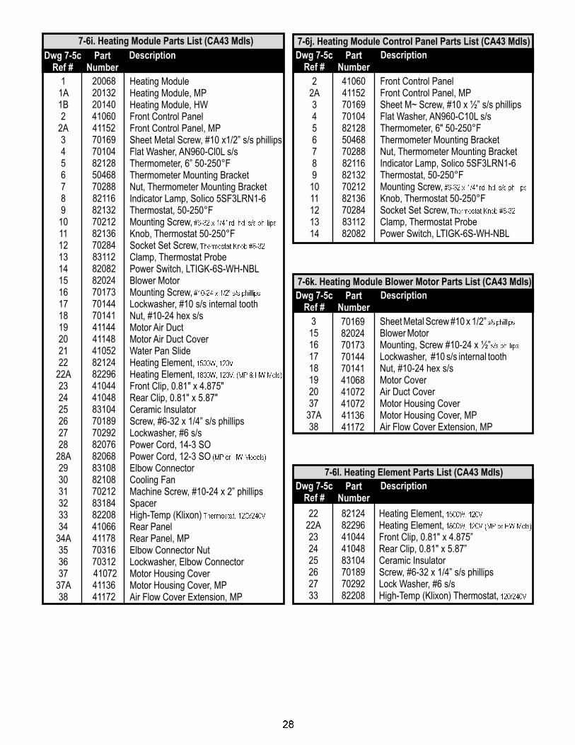
11A1B2
2A345678910111213141516171819202122
22A232425262728
28A293031323334
34A353637
37A38
200682013220140410604115270169701048212850468702888211682132702128213670284831128208282024701737014470141411444114841052821248229641044410488310470189702928207682068831088210870212831848220841066411787031670312410724113641172
Heating ModuleHeating Module, MPHeating Module, HWFront Control PanelFront Control Panel, MPSheet Metal Screw, #10 x1/2” s/s phillipsFlat Washer, AN960-Cl0L s/sThermometer, 6” 50-250°FThermometer Mounting BracketNut, Thermometer Mounting BracketIndicator Lamp, SoIico 5SF3LRN1-6Thermostat, 50-250°FMounting Screw,Knob, Thermostat 50-250°FSocket Set Screw,Clamp, Thermostat ProbePower Switch, LTIGK-6S-WH-NBLBlower MotorMounting Screw,Lockwasher, #10 s/s internal toothNut, #10-24 hex s/sMotor Air DuctMotor Air Duct CoverWater Pan SlideHeating Element,Heating Element,Front Clip, 0.81" x 4.875"Rear Clip, 0.81" x 5.87"Ceramic InsulatorScrew, #6-32 x 1/4” s/s phillipsLockwasher, #6 s/sPower Cord, 14-3 SOPower Cord, 12-3 SOElbow ConnectorCooling FanMachine Screw, #10-24 x 2” phillipsSpacerHigh-Temp (Klixon)Rear PanelRear Panel, MPElbow Connector NutLockwasher, Elbow ConnectorMotor Housing CoverMotor Housing Cover, MPAir Flow Cover Extension, MP
#6-32 x 1/4" rd. hd. s/s phillips
Thermostat Knob #8-32
#10-24 x 1/2� s/s phillips
1500W, 120V
1800W, 120V, (MP & HW Mdls)
(MP or HW Models)
Thermostat, 12O/240V
7-6i. Heating Module Parts List (CA43 Mdls)
Dwg 7-5cRef #
DescriptionPartNumber
22A34567891011121314
4106041152701697010482128504687028882116821327021282136702848311282082
Front Control PanelFront Control Panel, MPSheet M~ Screw, #10 x ½” s/s phillipsFlat Washer, AN960-C10L s/sThermometer, 6" 50-250°FThermometer Mounting BracketNut, Thermometer Mounting BracketIndicator Lamp, Solico 5SF3LRN1-6Thermostat, 50-250°FMounting Screw,Knob, Thermostat 50-250°FSocket Set Screw,Clamp, Thermostat ProbePower Switch, LTIGK-6S-WH-NBL
#6-32 x 1/4" rd. hd. s/s phillips
Thermostat Knob #8-32
7-6j. Heating Module Control Panel Parts List (CA43 Mdls)
Dwg 7-5cRef #
DescriptionPartNumber
7-6k. Heating Module Blower Motor Parts List (CA43 Mdls)
Dwg 7-5cRef #
DescriptionPartNumber
315161718192037
37A38
70169820247017370144701414106841072410724113641172
Sheet Metal Screw #10 x 1/2”Blower MotorMounting, Screw #10-24 x ½”Lockwasher, #10 s/s internal toothNut, #10-24 hex s/sMotor CoverAir Duct CoverMotor Housing CoverMotor Housing Cover, MPAir Flow Cover Extension, MP
s/s phillips
s/s phillips
Heating Element,Heating Element,Front Clip, 0.81" x 4.875”Rear Clip, 0.81" x 5.87”Ceramic InsulatorScrew, #6-32 x 1/4” s/s phillipsLock Washer, #6 s/sHigh-Temp (Klixon) Thermostat,
1500W, 120V
1800W, 120V (MP or HW Mdls)
120/240V
7-6l. Heating Element Parts List (CA43 Mdls)
Dwg 7-5cRef #
DescriptionPartNumber
2222A232425262733
8212482296410444104883104701897029282208
28
11A1B2
2A3
3A5
5A678910111213171920212223
23A24
24A25
25A262728293031323334353637
20068201322014020072200742007620124200802008250132501405073670073503925040050720830442008483008702578310041041831808402850744508185074450818508107027680036800407006870040703242008620162300282016050820
Heating ModuleHeating Module, MPHeating Module, HWCabinet AssemblyCabinet Assembly, MPFront DoorFront Door for MPRear DoorRear Door, MPDoor Hinge, 2”Cabinet Hinge, 3”Hinge Pin, 5/16" x 5" rodMachine Screw, 1/4”-20 x 1/2"LatchLatch StrikeLatch Pin, 5/16" x 8.5" rodLatch Spring #CDL5019Air Duct Assembly (CV13)Button, aluminum #l0-23-75RSheet Metal Screw, T/H #8 x 1/4”Water PanBaffle, 22 ga. 7" x 8.5"Door Gasket, magneticDoor Gasket, magneticGasket Retainer, top outerGasket Retainer, top outerGasket Retainer, bottom outerGasket Retainer, bottom outerGasket Retainer, side outerSheet Metal Screw, #6 x 3/4" hex headCaster, 5” with brakeCaster, 5” without brakeNut, hex 5/16-18Lockwasher, 5/16" internal toothBolt, hex 5/16"-18 x 1 1/4"Air Duct Assembly (CV7)Air Duct Assembly (CVMP6)Wire Hanger, MPAir Duct Assembly (CVMP7)Extruded Runner, MP
phillips
phillips
21.5" x 28.5�, MP
26� x 28.5", MP
22.37�
26.87�, MP
22.37"
26.87", MP
29.5"
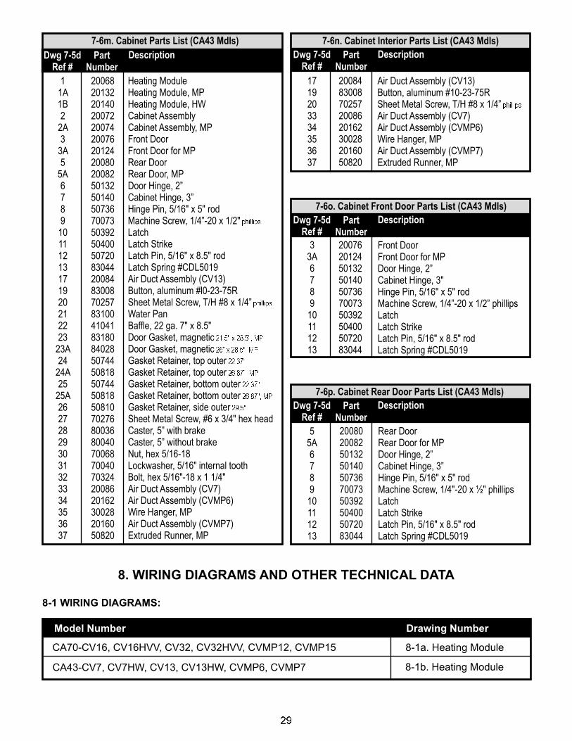
7-6m. Cabinet Parts List (CA43 Mdls)
Dwg 7-5dRef #
DescriptionPartNumber
7-6n. Cabinet Interior Parts List (CA43 Mdls)
Dwg 7-5dRef #
DescriptionPartNumber
1719203334353637
2008483008702572008620162300282016050820
Air Duct Assembly (CV13)Button, aluminum #10-23-75RSheet Metal Screw, T/H #8 x 1/4”Air Duct Assembly (CV7)Air Duct Assembly (CVMP6)Wire Hanger, MPAir Duct Assembly (CVMP7)Extruded Runner, MP
phillips
33A678910111213
20076201245013250140507367007350392504005072083044
Front DoorFront Door for MPDoor Hinge, 2”Cabinet Hinge, 3"Hinge Pin, 5/16" x 5" rodMachine Screw, 1/4”-20 x 1/2” phillipsLatchLatch StrikeLatch Pin, 5/16" x 8.5" rodLatch Spring #CDL5019
7-6o. Cabinet Front Door Parts List (CA43 Mdls)
Dwg 7-5dRef #
DescriptionPartNumber
7-6p. Cabinet Rear Door Parts List (CA43 Mdls)
Dwg 7-5dRef #
DescriptionPartNumber
55A678910111213
20080200825013250140507367007350392504005072083044
Rear DoorRear Door for MPDoor Hinge, 2”Cabinet Hinge, 3”Hinge Pin, 5/16" x 5" rodMachine Screw, 1/4"-20 x ½" phillipsLatchLatch StrikeLatch Pin, 5/16" x 8.5" rodLatch Spring #CDL5019
8. WIRING DIAGRAMS AND OTHER TECHNICAL DATA
8-1 WIRING DIAGRAMS:
CA70-CV16, CV16HVV, CV32, CV32HVV, CVMP12, CVMP15
Model Number Drawing Number
8-1a. Heating Module
CA43-CV7, CV7HW, CV13, CV13HW, CVMP6, CVMP7 8-1b. Heating Module
29

30
Notes:
IMPORTANT FOR FUTURE REFERENCE
Please complete this information and retain this manual for the life of the equipment. ForWARRANTY SERVICE and/or PARTS, this information is required.
Model Number Serial Number Date Purchased

31
Notes:

Phone: +1Fax: +1 (214) 565-0976Toll Free: +1 (800) 441-1601Website: www.BevLes.comE-mail: [email protected]
(214) 421-7366
BevLes729 Third AvenueDallas, TX 75226
Innovative Foodservice Equipment CustomDesigned for Performance, Service and Value.
32