Embed Size (px)
Citation preview

Instruction Manual
ControlNet™ Network CommunicationOption Board For Use WithFlexPak™ 3000 and WebPak™ 3000DC DrivesM/N 915FK2101
D2-3425-3

©2005 Rockwell International Corporation
The information in this manual is subject to change without notice.
Throughout this manual, the following notes are used to alert you to safety considerations:
Important: Identifies information that is critical for successful application and understanding of the product.
The thick black bar shown on the outside margin of this page will be used throughout this instruction manual to signify new or revised text or figures.
!ATTENTION: Identifies information about practices or circumstances that can lead to personal injury or death, property damage, or economic loss.
ControlNet is a trademark of ControlNet International, Ltd.FlexPak, WebPak, RSNetWorx, ControlLogix, and Reliance are trademarks of Rockwell Automation.
!ATTENTION: Only qualified electrical personnel familiar with the construction and operation of this equipment and the hazards involved should install, adjust, operate, or service this equipment. Read and understand this manual and other applicable manuals in their entirety before proceeding. Failure to observe this precaution could result in severe bodily injury or loss of life.
ATTENTION: The user is responsible for conforming with all applicable local, national, and international codes. Wiring practices, grounding, disconnects, and overcurrent protection are of particular importance. Failure to observe this precaution could result in severe bodily injury or loss of life.
ATTENTION: Do not install modification boards with power applied to the drive. Disconnect and lock out incoming power before attempting such installation. Failure to observe this precaution could result in severe bodily injury or loss of life.
ATTENTION: The drive contains ESD- (Electrostatic Discharge) sensitive parts and assemblies. Static control precautions are required when installing, testing, servicing, or repairing the drive. Erratic machine operation and damage to, or destruction of, equipment can result if this procedure is not followed. Failure to observe this precaution can result in bodily injury.

Contents I
CONTENTS
Chapter 1 Introduction1.1 Network Option Board Description .................................................................. 1-11.2 Where To Find Additional Information ............................................................. 1-31.3 Getting Assistance from Reliance Electric....................................................... 1-3
Chapter 2 Installation2.1 Installing the Network Option Board ................................................................ 2-12.2 Connecting the Drive to a ControlNet Network................................................ 2-32.3 Connecting a Programming Device to the Option Board’s Network Access Port...................................................................................................... 2-4
Chapter 3 Drive Configuration3.1 Setting NETW DROP NUMBER (P.900) ......................................................... 3-13.2 Setting CONTROL SOURCE SELECT (P.000)............................................... 3-13.3 Setting CNI PROG/RUN MODE (P.915) ......................................................... 3-23.4 Setting NETW COMM LOSS SELECT (P.901) (FlexPak 3000 Drives Only) .. 3-23.5 Setting NETW OUT REG 1 SELECT (P.902).................................................. 3-33.6 Setting NETW OUT REG 2 SELECT (P.903).................................................. 3-43.7 Setting NETW OUT REG 3 SELECT (P.904).................................................. 3-43.8 NETW COMM STATUS (P.908)...................................................................... 3-43.9 NETW TYPE & VERSION (P.909) .................................................................. 3-43.10 NETWORK KIT (P.796)................................................................................... 3-53.11 NETW IN REG 1 (P.905) ................................................................................. 3-53.12 NETW IN REG 2 (P.906) ................................................................................. 3-53.13 NETW IN REG 3 (P.907) ................................................................................. 3-5
Chapter 4 Programming the Drive4.1 About ControlNet Network Communication..................................................... 4-14.2 Configuring Drive Reference and Feedback Data as Scheduled Transfers.... 4-2
4.2.1 Configuring Scheduled Data Transfers ................................................. 4-24.2.2 Programming Scheduled Drive Reference Data ................................... 4-34.2.3 Using Scheduled Drive Feedback Data ................................................ 4-6
4.3 Using Unscheduled Transfers ......................................................................... 4-84.3.1 About MSG Instruction Timing .............................................................. 4-94.3.2 About the Files You Can Access........................................................... 4-94.3.3 Using the Drive Parameters Data (N10:x)............................................. 4-94.3.4 Using the Drive Display Data (N11:x).................................................. 4-104.3.5 Using the Drive Reference and Feedback Data (N12:x) ..................... 4-104.3.6 Using the Write Status (File N20:x) to Troubleshoot a Drive Parameter ................................................................................ 4-10
Chapter 5 Configuring ControlLogix Applications
Chapter 6 Configuring SLC500 Applications6.1 Required Software and Equipment.................................................................. 6-16.2 Network Configuration ..................................................................................... 6-26.3 1747-KFC15 Set Up ........................................................................................ 6-3
II ControlNet Network Communication Option Board For Use With FlexPak 3000 and WebPak 3000 DC Drives
6.4 Scheduled Messaging (I/O)..............................................................................6-56.5 Unscheduled Messaging..................................................................................6-66.6 SLC500 Support...............................................................................................6-7
Chapter 7 Register Map for FlexPak 3000 Drives
Chapter 8 Register Map for WebPak 3000 Drives
Chapter 9 Communication Error Codes

Contents III
List of Figures
Figure 1.1 – ControlNet Network Communication Option Board .............................. 1-2
Figure 2.1 – Opening the Carrier .............................................................................. 2-1Figure 2.2 – Removing the Carrier Shield ................................................................ 2-2Figure 2.3 – Removing the Shield Ground Wire ....................................................... 2-2Figure 2.4 – Installing the Network Communication Option Board ........................... 2-3Figure 2.5 – Connecting a FlexPak 3000 Drive or a WebPak 3000 Drive to the Control-
Net Network.......................................................................................... 2-4
Figure 4.1 – Drive Information Map .......................................................................... 4-9
Figure 5.1 – RSLogix 5000: I/O Configuration Selection .......................................... 5-1Figure 5.2 – RSLogix 5000: New Module Selection ................................................. 5-2Figure 5.3 – Select Module Type: 1756-CNB/B Selection........................................ 5-2Figure 5.4 – Module Properties: Name Selection ..................................................... 5-3Figure 5.5 – Module Properties: Controller-to-Module Behavior Screen.................. 5-3Figure 5.6 – Module Properties: Identification/Status Screen................................... 5-4Figure 5.7 – Module Properties: Informational Screen ............................................. 5-4Figure 5.8 – RSLogix 5000: I/O Configuration Folder............................................... 5-5Figure 5.9 – RSLogix 5000: New Module Selection Screen..................................... 5-5Figure 5.10 – Select Drive Type: FlexPak 3000 ....................................................... 5-6Figure 5.11 – Module Properties: Name Selection ................................................... 5-6Figure 5.12 – Module Properties: RPI Selections..................................................... 5-7Figure 5.13 – Module Properties: Cnet_Bridge ........................................................ 5-7Figure 5.14 – RSLogix: Configure Additional Nodes Screen.................................... 5-8Figure 5.15 – RSLogix 5000: Module-Defined Screen ............................................. 5-8Figure 5.16 – Download to the Controller Dialog Box............................................... 5-9Figure 5.17 – RSLogix: Attention Symbol................................................................. 5-9Figure 5.18 – RSNetWorx for ControlNet Screen................................................... 5-10
Figure 6.1 – Network Configuration: Connection Properties .................................... 6-2Figure 6.2 – Channel Configuration: Chan 0-System............................................... 6-3Figure 6.3 – Controller Properties: Controller Communications ............................... 6-4Figure 6.4 – 1747-KFC15 Set Up ............................................................................. 6-4Figure 6.5 – Scheduled Messaging Example 1a ...................................................... 6-5Figure 6.6 – Scheduled Messaging Example 1b ...................................................... 6-6Figure 6.7 – Unscheduled Messaging Setup Screen ............................................... 6-6Figure 6.8 – Unscheduled Messaging Example ....................................................... 6-7

IV ControlNet Network Communication Option Board For Use With FlexPak 3000 and WebPak 3000 DC Drives

Contents V
List of Tables
Table 4.1 – Network Update Time Components...................................................... 4-1Table 4.2 – ControlNet Scheduled Traffic Configuration Fields................................ 4-2Table 4.3 – Data Sent/Received 8 Words (Maximum) ............................................. 4-3Table 4.4 – FlexPak 3000 Scheduled Drive Reference Data ................................... 4-4Table 4.5 – WebPak 3000 Scheduled Drive Reference Data................................... 4-5Table 4.6 – FlexPak 3000 Scheduled Drive Feedback Data .................................... 4-7Table 4.7 – WebPak 3000 Scheduled Drive Feedback Data ................................... 4-8
Table 6.1 – Required Software and Equipment........................................................ 6-1
Table 7.1 – File N10:x (Drive Read/Write Parameters) for FlexPak 3000 Drives..... 7-1Table 7.2 – File N11:x (Drive Display Data (Read Only)) for FlexPak 3000 Drives 7-11Table 7.3 – File N12:x (Drive Reference and Feedback Data) for FlexPak 3000 Drives..................................................................................................... 7-16
Table 8.1 – File N10:x (Drive Read/Write Parameters) for WebPak 3000 Drives .... 8-1Table 8.2 – File N11:x (Drive Display Data (Read Only)) for WebPak 3000 Drives8-17Table 8.3 – File N12:x (Drive Reference and Feedback Data) for WebPak 3000 Drives..................................................................................................... 8-23
Table 9.1 – Error Codes ........................................................................................... 9-1

VI ControlNet Network Communication Option Board For Use With FlexPak 3000 and WebPak 3000 DC Drives

Introduction 1-1
CHAPTER 1Introduction
This manual describes the ControlNet™ Network Communication Option board. (M/N 915FK2101). This kit allows a FlexPak™ 3000 or a WebPak™ 3000 DC drive to send and receive data via a control processor over the ControlNet network.
WebPak 3000 drives (version 1.1 or later) require version 2.2 or later of the ControlNet Network Option board. FlexPak 3000 drives (version 4.2 or later) are compatible with all versions of the network option board.
Unless specified otherwise, the material in this manual applies to both FlexPak 3000 and WebPak 3000 drives.
1.1 Network Option Board Description
The ControlNet Network Communication Option board makes the drive a slave node on the ControlNet network. It is a printed circuit board assembly that mounts inside the drive and connects to the drive’s Regulator board through a ribbon cable. The network option board is powered from the standard drive power supply.
The network option board has an RJ-45 connector that is used as a Network Access Port (NAP) that allows temporary access to the network and/or products connected to the network. A 9-pin D-shell connector is used for RS-232 communication to program the flash memory on the board. Two BNC connectors are used for ControlNet communication. A drop cable is used to link each BNC connector through a passive tap to the network.
The network option board contains its own microprocessor. The microprocessor connects to one port of the board’s dual-port memory. The other port interfaces with the drive’s Regulator board.
The ControlNet Network Communication Option board is shown in figure 1.1.

1-2 ControlNet Network Communication Option Board For Use With FlexPak 3000 and WebPak 3000 DC Drives
Figure 1.1 – ControlNet Network Communication Option Board
RS-232Connector
Ribbon Cable Connector
BNC Connectors
RJ-45 Connector(Network Access Port)

Introduction 1-3
1.2 Where To Find Additional InformationYou must be familiar with all the instruction manuals that describe your system. This can include, but is not limited to:
• FlexPak 3000 DC Drive Hardware Reference, D2-3404
• FlexPak 3000 DC Drive Software Reference, D2-3405
• WebPak 3000 DC Drive Hardware Reference, D2-3443
• WebPak 3000 DC Drive Software Reference, D2-3444
• ControlNet Network System Overview, 1786-2.9
• ControlNet Cable System Component List, AG-2.2
• ControlNet Cable Planning and Installation Manual, 1786-6.2.1
• ControlNet Coax Tap Installation Manual, 1786-5.7
• ControlNet Network Access Cable Installation Instructions, 1786-2.6
• ControlNet Repeater Installation Instructions, 1786-5.8
You can obtain the ControlNet manuals listed above from The Automation Bookstore at http://www.theautomationbookstore.com.
1.3 Getting Assistance from Reliance Electric
If you have any questions or problems with the products described in this instruction manual, contact your local Reliance Electric sales office.
For technical assistance, call 1-800-726-8112. Before calling, please review the troubleshooting section of this manual and check the standard drives website for additional information. When you call this number, you will be asked for the drive model number and this instruction manual number. Also, please have your product version number ready.

1-4 ControlNet Network Communication Option Board For Use With FlexPak 3000 and WebPak 3000 DC Drives

Installation 2-1
CHAPTER 2Installation
This section describes how to install the network option board in the drive and connect the drive to a ControlNet network.
2.1 Installing the Network Option Board
To install the network option board:
Step 1. Turn off, lock out, and tag all incoming power to the drive.
Step 2. Loosen the two (2) OIM cover retaining screws and remove the cover.
Step 3. Loosen the captive screw on the carrier. Swing open the carrier. See figure 2.1.
!ATTENTION: Only qualified electrical personnel familiar with the construction and operation of this equipment and the hazards involved should install, adjust, operate, or service this equipment. Read and understand this manual and other applicable manuals in their entirety before proceeding. Failure to observe this precaution could result in severe bodily injury or loss of life.
ATTENTION: The user is responsible for conforming with all applicable local, national, and international codes. Wiring practices, grounding, disconnects, and overcurrent protection are particularly important. Failure to observe this precaution could result in severe bodily injury or loss of life.
ATTENTION: Do not install modification boards with power applied to the drive. Disconnect and lock out incoming power before attempting such installation. Failure to observe this precaution could result in severe bodily injury or loss of life.
Figure 2.1 – Opening the Carrier
Loosen Captive Screw and Swing Carrier Open
2-2 ControlNet Network Communication Option Board For Use With FlexPak 3000 and WebPak 3000 DC Drives
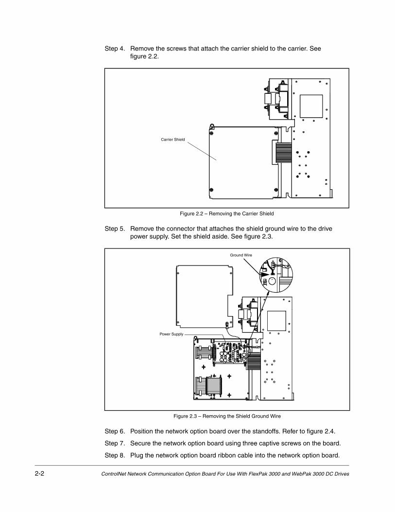
Step 4. Remove the screws that attach the carrier shield to the carrier. See figure 2.2.
Step 5. Remove the connector that attaches the shield ground wire to the drive power supply. Set the shield aside. See figure 2.3.
Step 6. Position the network option board over the standoffs. Refer to figure 2.4.
Step 7. Secure the network option board using three captive screws on the board.
Step 8. Plug the network option board ribbon cable into the network option board.
Figure 2.2 – Removing the Carrier Shield
Figure 2.3 – Removing the Shield Ground Wire
Carrier Shield
Ground Wire
Power Supply

Installation 2-3
Step 9. Reattach the carrier shield ground wire to the drive power supply.
Step 10. Reattach the carrier shield to the carrier.
Step 11. Close the carrier and fasten it with the captive screw.
Step 12. Reinstall the drive cover.
2.2 Connecting the Drive to a ControlNet Network
See figure 2.5 for cabling and termination connections.
Refer to the ControlNet Cable Planning and Installation Manual, 1786-6.2.1, for a detailed description of how to add a node to the network.
Step 1. Lock out and tag all power to the drive.
Step 2. Connect the ControlNet cable tap(s) to the ControlNet media and the network option board.
To connect to the network option board, twist the ControlNet cable tap(s) onto the BNC connectors. You will hear the tap(s) click into a locked position.
Step 3. Remove the lockout and tag. Apply power to the drive.
If a problem is detected during diagnostics, a fault or alarm will occur. Refer to the FlexPak 3000 Software Reference Manual, D2-3405, or the WebPak 3000 Hardware Reference Manual, D2-3443, for information on faults and alarms.
Figure 2.4 – Installing the Network Communication Option Board
Attach Network board to carrier’s molded standoffs using captive screws (qty. 3)
Plug option board ribbon cable into Network board

2-4 ControlNet Network Communication Option Board For Use With FlexPak 3000 and WebPak 3000 DC Drives
You can run a second trunk cable between your ControlNet nodes for redundant media. With redundant media, nodes send signals on two separate segments. The receiving node automatically compares the quality of the two signals and accepts the better signal. This also provides a backup cable should one cable fail. When using redundant media, you must use two passive taps.
If you do not use redundant media, the option board can operate using only channel A or channel B, as long as all other drops on the network are also on the same channel.
2.3 Connecting a Programming Device to the Option Board’s Network Access Port
You can gain full access to the ControlNet network by connecting a programming device to the option board’s Network Access Port, an RJ-45 connector.
Important: Be sure to use a network access cable that is approved by a ControlNet vendor. Using an unsuitable cable could result in network failures.
Figure 2.5 – Connecting a FlexPak 3000 Drive or a WebPak 3000 Drive to the ControlNet Network
ProgrammableLogic Controller(PLC)
Tap
Drop Cable
Trunk Cable
Repeater
Terminator
FlexPak 3000 or
Note: This diagram showsredundant mediabeing used.
WebPak 3000 Drive

Drive Configuration 3-1
CHAPTER 3Drive Configuration
This chapter describes how to configure a drive for use with a ControlNet network. The sections that follow describe all of the FlexPak 3000 and WebPak 3000 drive parameters related to ControlNet operation.
3.1 Setting NETW DROP NUMBER (P.900)
Use NETW DROP NUMBER (P.900) to assign a node number to the drive. The node number can be changed (through a local operator interface) only when the drive is stopped. This parameter cannot be written over the ControlNet network.
The node number must be changed to a value greater than 1 to begin ControlNet communication. After the network has been configured and after NETW DROP NUMBER is set to a value greater than 1, NETW COMM STATUS (P.908) should indicate ACTIVE.
If the node number is changed from any value other than 1, the new value must be saved to non-volatile memory and then the power to the drive must be turned off and back on to have the new value take effect.
If NETW DROP NUMBER is not equal to 1 on power up, the drive will attempt to communicate on the ControlNet network immediately after the drive diagnostics are complete.
Range: 1 - 99
Type: Non-volatile, Configuration (Read-only over the ControlNet network)
Default: 1 (Drive is not communicating on the network)
3.2 Setting CONTROL SOURCE SELECT (P.000)
CONTROL SOURCE SELECT (P.000) determines the source of control information for the drive (start, jog, direction, etc.). Setting CONTROL SOURCE SELECT to NETWORK allows the drive to be controlled, and the reference to be supplied, from the ControlNet network. After CONTROL SOURCE SELECT is set to NETWORK, the LCD status on the OIM keypad should change to show the network is in control of the drive.
Note that setting CONTROL SOURCE SELECT to any value but NETWORK does not prevent the drive from communicating on the ControlNet network. In other words, CONTROL SOURCE SELECT does not have to be set to NETWORK to modify or read drive parameters.
Range: TERMBLK (1), KEYPAD (2), SERIAL (3), NETWORK (4)
Type: Non-volatile, Configuration
Default: TERMBLK (1)

3-2 ControNet Network Communication Option Board For Use With FlexPak 3000 and WebPak 3000 DC Drives
3.3 Setting CNI PROG/RUN MODE (P.915)
CNI PROG/RUN MODE (P.915) selects how the drive will respond when communicating with a PLC that is put into program mode while CONTROL SOURCE SELECT (P.000) is set to NETWORK. When the PLC is put into program mode, alarm A00006 (CNI PROGRAM MODE), is generated to indicate the change in operation of the drive. An alarm is not generated when the PLC is returned to run mode, since that is considered normal operation.
When CNI PROG/RUN MODE = STOP (1), the drive will coast/DB stop when the PLC is put into program mode. The drive can be started only when the PLC is in run mode.
When CNI PROG/RUN MODE = USE LAST REF (2), the drive will not stop (if running) or start (if stopped) when the PLC is put into program mode. The drive will continue to use the last network reference received as its speed reference. This will continue until the PLC is returned to run mode and a new reference value is received.
When CNI PROG/RUN MODE = USE TRMBLK CNTL (3), the drive will not stop (if running) or start (if stopped) when the PLC is put into program mode (or returned to run mode). The drive's terminal block will become the source for all control (run, jog, stop, fault reset, direction and OCL enable) and speed (auto) reference signals.
For FlexPak 3000 drives, the Speed Loop PI Reset and Underwind/Overwind bits cannot be changed while operating in this mode. They will remain at the last values received from the network. This will continue until the PLC is returned to run mode when control/reference will come from the network again.
Range: STOP (1), USE LAST REF (2), USE TRMBLK CNTL (3)
Type: Non-volatile, Configuration
Default: STOP (1)
3.4 Setting NETW COMM LOSS SELECT (P.901) (FlexPak 3000 Drives Only)
NETW COMM LOSS SELECT (P.901) is not used in WebPak 3000 drives. For WebPak 3000 drives, a fault is generated when network communication is lost if CONTROL SOURCE SELECT (P.000) is set to NETWORK. This causes the drive to coast/DB stop. The drive cannot be restarted until the fault is cleared.
!ATTENTION: CNI PROG/RUN MODE (P.915) allows you to configure the drive to continue to run when the PLC is put into program mode. You must provide some form of hardwired stop in case of communication loss, since stopping the drive through the network might not be possible. Failure to observe this precaution could result in bodily injury or damage to, or destruction of, equipment.
!ATTENTION: NETW COMM LOSS SELECT (P.901) allows you to configure the drive to continue to run if a loss of network communication occurs. You must provide some form of hardwired stop in case of communication loss, since stopping the drive through the network might not be possible. Failure to observe this precaution could result in bodily injury or damage to, or destruction of, equipment.

Drive Configuration 3-3
For FlexPak 3000 drives, NETW COMM LOSS SELECT (P.901) defines how the drive will respond to network communication loss when CONTROL SOURCE SELECT (P.000) is set to NETWORK. Alarms do not cause the drive to stop. Therefore, some form of hardwired stop must be available in case of communication loss, since stopping the drive through the network might not be possible.
When NETW COMM LOSS SELECT = FAULT (1), a fault is generated when network communication is lost, causing the drive to coast/DB stop. The drive can not be restarted until the fault is cleared.
When NETW COMM LOSS SELECT = HOLD LAST REF (2), the drive continues to run if network communication is lost, using the last reference value received over the network. Alarm A00004 (NETWORK COMMUNICATION TIMEOUT) is generated if network communication is lost. The drive will maintain the last reference until network communication is reestablished and a new drive reference value is provided.
When NETW COMM LOSS SELECT = USE TRMBLK REF (3), the drive continues to run if network communication is lost, using the selected auto reference value from the regulator board terminal strip (terminals 19 and 20). The drive automatically switches back to the network reference when network communication is re-established. Alarm A00004 (NETWORK COMMUNICATION TIMEOUT) is generated if network communication is lost. The drive can still be stopped through the terminal block and local keypad, but can not be restarted.
When NETW COMM LOSS SELECT = USE TRMBLK CNTL (4), the drive continues to run if network communication is lost. The Regulator board terminal strip will become the source for all control (run, jog, stop, fault reset, direction and OCL enable) and speed (auto) reference signals. The Speed Loop PI Reset and Underwind/Overwind bits can not be changed while operating in this mode. They will remain at the last values received from the network. The drive automatically switches back to the network reference and control when network communication is re-established. Alarm A00004 (NETWORK COMMUNICATION TIMEOUT) Is generated if network communication is lost.
Range: FAULT (1), HOLD LAST REF (2), USE TRMBLK REF (3), USE TRMBLK CNTL (4)
Type: Non-volatile, Tunable
Default: FAULT (1)
3.5 Setting NETW OUT REG 1 SELECT (P.902)
NETW OUT REG 1 SELECT (P.902) defines a parameter number whose value will be monitored and saved in the network option board’s dual-port memory. For example, setting this parameter equal to 588 will cause the value of FIELD DELTA (P.588) to be written to file address N10:47 in the dual-port memory for FlexPak 3000 drives, address N10:87 for WebPak 3000 drives.
Range: -32768 to 32767
Type: Non-volatile, Tunable
Default: 0

3-4 ControNet Network Communication Option Board For Use With FlexPak 3000 and WebPak 3000 DC Drives
3.6 Setting NETW OUT REG 2 SELECT (P.903)
NETW OUT REG 2 SELECT (P.903) defines a parameter number whose value will be monitored and saved in the network option board’s dual-port memory. For example, setting this parameter equal to 588 will cause the value of FIELD DELTA (P.588) to be written to file address N10:48 in the dual-port memory for FlexPak 3000 drives, address N10:88 for WebPak 3000 drives.
Range: -32768 to 32767
Type: Non-volatile, Tunable
Default: 0
3.7 Setting NETW OUT REG 3 SELECT (P.904)
NETW OUT REG 3 SELECT (P.904) defines a parameter number whose value will be monitored and saved in the network option board’s dual-port memory. For example, setting this parameter equal to 588 will cause the value of FIELD DELTA (P.588) to be written to file address N10:49 in the dual-port memory for FlexPak 3000 drives, address N10:89 for WebPak 3000 drives.
Range: -32768 to 32767
Type: Non-volatile, Tunable
Default: 0
3.8 NETW COMM STATUS (P.908)
NETW COMM STATUS (P.908) indicates the status of network communication.
When NETW COMM STATUS = NOT ACTIVE, the network option board is not communicating on the ControlNet network.
When NETW COMM STATUS = ACTIVE, the network option board is communicating properly with the ControlNet network.
Range: NOT ACTIVE (1), ACTIVE (2)
Type: Read-only (output)
3.9 NETW TYPE & VERSION (P.909)
NETW TYPE & VERSION indicates the type of network board installed and its software version. The format is of the form TV.VV, where:
T = board type:2 = AutoMax, Profibus, InterBus4 = DeviceNet (FlexPak 3000 drives only)5 = ControlNet
V.VV = major and minor version numbers (e.g. 1.03)
Range: 10.00 to 99.99
Type: Read-only (output)
Drive Configuration 3-5
3.10 NETWORK KIT (P.796)
NETWORK KIT (P.796) indicates whether the network option board is operating correctly in the drive.
Range: PRESENT (1), NOT PRESENT (2), FAILED DIAGS (3)
Type: Read-only (output)
3.11 NETW IN REG 1 (P.905)
NETW IN REG 1 (P.905) indicates the value being written by the network master into file address N11:10 in the network option board’s dual-port memory.
Range: -4095 to 4095
Type: Read-only (output)
3.12 NETW IN REG 2 (P.906)
NETW IN REG 2 (P.906) indicates the value being written by the network master into file address N11:11 in the network option board’s dual-port memory.
Range: -4095 to 4095
Type: Read-only (output)
3.13 NETW IN REG 3 (P.907)
NETW IN REG 3 (P.907) indicates the value being written by the network master into file address N11:12 in the network option board’s dual-port memory.
Range: -4095 to 4095
Type: Read-only (output)

3-6 ControNet Network Communication Option Board For Use With FlexPak 3000 and WebPak 3000 DC Drives
Programming the Drive 4-1
CHAPTER 4Programming the Drive
This section describes how to program the drive over the ControlNet network.
4.1 About ControlNet Network Communication
The ControlNet network transports time-critical control information (for example, drive reference and feedback information) as scheduled data, as well as non-time-critical information (for example, accessing drive parameters) as unscheduled data. The transportation of the non-time-critical information does not interfere with the time critical messages.
A node’s access to the network is controlled by a time-slice access algorithm, which determines a node’s opportunity to transmit in each network update interval. You configure how often the network update interval repeats by selecting a network update time (NUT) in milliseconds. The minimum network update time you can specify is 2 ms.
The network update time is how often you want to send scheduled traffic. You configure when a node will transmit during the network update time (scheduled vs. unscheduled). See table 4.1 for more information about the components of the network update time.
For optimum throughput, assign addresses to ControlNet nodes in a sequential order.
Table 4.1 – Network Update Time Components
Network Update Time Component Function
scheduled Information that is time-critical (drive reference and feedback) should be sent during this part of the NUT interval.
unscheduled Information that can be delivered without time constraints should be sent during this part of the NUT interval.
The amount of time available for the unscheduled portion is determined by the traffic load of the scheduled portion. During this part of the interval, nodes may have many or no chances to transmit.

4-2 ControlNet Network Communication Option Board For Use With FlexPak 3000 and WebPak 3000 DC Drives
4.2 Configuring Drive Reference and Feedback Data as Scheduled Transfers
This section describes how to:
• configure scheduled traffic for the drive
• control the drive using the drive reference data
• use scheduled drive feedback data
4.2.1 Configuring Scheduled Data Transfers
Before the drive can communicate on the ControlNet network, you must configure its scheduled traffic information by using some type of ControlNet configuration software. By configuring scheduled traffic, you define how much data the drive can send, how often the data is sent, and where the data is written to and read from (mapped) in the programmable controller.
You must configure each drive on the ControlNet network. Table 4.2 lists the configuration information you must enter if you are using RSNetWorx™ and a PLC-5™.
Table 4.2 – ControlNet Scheduled Traffic Configuration Fields
In this field: Enter this information:
Node Enter the drive’s node number that you defined in P.900.
Slot Message
These fields are not used by the drive.
Module Enter FlexPak 3000 or WebPak 3000.
API This field is read-only.
RPI Enter how often you want to exchange scheduled data between the programmable controller and the drive.
Connection Type Select “Exclusive Owner.”FlexPak 3000 and WebPak 3000 drives do not support Multicast operation.
Input Address Enter the programmable controller’s integer file number that will store data received from the drive (drive feedback data).
Input Size Enter the number of words of drive feedback data that you want the programmable controller to receive from the drive (1 to 8). See section 4.2.3 for information about the type of data that is sent.
Output Address Enter the programmable controller’s integer file number that will store data sent to the drive (drive reference data).
Output Size Enter the number of words of drive reference data that you want the programmable controller to send to the drive (1 to 8).See section 4.2.2 for information about the type of data that is sent.
Status Address Enter the programmable’s integer file number that will store the status of the ControlNet connection to the drive.
Config AddressConfig Size
These fields are not used by the drive.

Programming the Drive 4-3
4.2.2 Programming Scheduled Drive Reference Data
Setting CONTROL SOURCE SELECT to NETWORK allows the scheduled data from the PLC to control the drive. If CONTROL SOURCE SELECT ≠ NETWORK, then scheduled drive reference data from the ControlNet network is not used.
The scheduled drive reference data can be configured as one to eight words of data. The first word of the scheduled drive reference data is always the drive control word; it is written in element 0 of the Output file. Should you configure less than eight words of output data, you can access the Scheduled Drive Reference Data through file N12 (see section 4.3) as unscheduled data messages.
You must create a drive control application program to run in the programmable controller. This application program must write from one to eight words of data to the file you defined during drive configuration as the Output Address. The value you defined as the Output Size determines how many words of data the option board can accept from the programmable controller. During a scheduled data transfer, the programmable controller writes the data contained in the Output Address to the option board.
Reference and control information is scanned by the drive at different rates depending on the type of data and the drive operating mode (speed regulator or voltage regulator). If the drive is configured as a speed regulator, all of the reference inputs are evaluated every 5 ms for FlexPak 3000 drives, every 10 ms for WebPak 3000 drives. If the drive is configured as a voltage regulator, all of the reference inputs are scanned every 10 ms. The drive control bits are always evaluated every 20 ms.
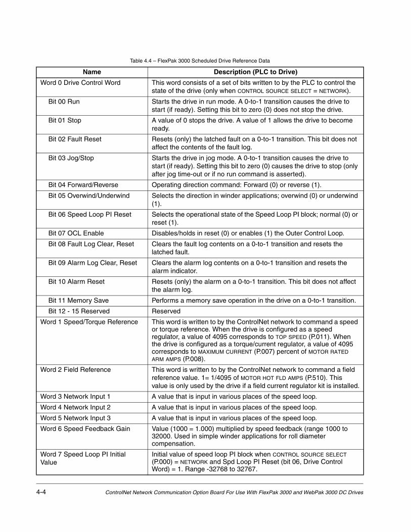
Table 4.4 describes the function of each word of the FlexPak 3000 scheduled drive reference data. Table 4.5 describes the function of each word of the WebPak 3000 scheduled drive reference data.
Table 4.3 – Data Sent/Received 8 Words (Maximum)
PLC to Drive FlexPak WebPak
Word 0 Control Control
Word 1 Reference Reference
Word 2 Reference Network 1
Word 3 Network 1 Network 2
Word 4 Network 2 Network 3
Word 5 Network 3 Field Reference
Word 6 Speed FB. Gain Not Used
Word 7 Speed Loop PI Not Used
4-4 ControlNet Network Communication Option Board For Use With FlexPak 3000 and WebPak 3000 DC Drives
Table 4.4 – FlexPak 3000 Scheduled Drive Reference Data
Name Description (PLC to Drive)
Word 0 Drive Control Word This word consists of a set of bits written to by the PLC to control the state of the drive (only when CONTROL SOURCE SELECT = NETWORK).
Bit 00 Run Starts the drive in run mode. A 0-to-1 transition causes the drive to start (if ready). Setting this bit to zero (0) does not stop the drive.
Bit 01 Stop A value of 0 stops the drive. A value of 1 allows the drive to become ready.
Bit 02 Fault Reset Resets (only) the latched fault on a 0-to-1 transition. This bit does not affect the contents of the fault log.
Bit 03 Jog/Stop Starts the drive in jog mode. A 0-to-1 transition causes the drive to start (if ready). Setting this bit to zero (0) causes the drive to stop (only after jog time-out or if no run command is asserted).
Bit 04 Forward/Reverse Operating direction command: Forward (0) or reverse (1).
Bit 05 Overwind/Underwind Selects the direction in winder applications; overwind (0) or underwind (1).
Bit 06 Speed Loop PI Reset Selects the operational state of the Speed Loop PI block; normal (0) or reset (1).
Bit 07 OCL Enable Disables/holds in reset (0) or enables (1) the Outer Control Loop.
Bit 08 Fault Log Clear, Reset Clears the fault log contents on a 0-to-1 transition and resets the latched fault.
Bit 09 Alarm Log Clear, Reset Clears the alarm log contents on a 0-to-1 transition and resets the alarm indicator.
Bit 10 Alarm Reset Resets (only) the alarm on a 0-to-1 transition. This bit does not affect the alarm log.
Bit 11 Memory Save Performs a memory save operation in the drive on a 0-to-1 transition.
Bit 12 - 15 Reserved Reserved
Word 1 Speed/Torque Reference This word is written to by the ControlNet network to command a speed or torque reference. When the drive is configured as a speed regulator, a value of 4095 corresponds to TOP SPEED (P.011). When the drive is configured as a torque/current regulator, a value of 4095 corresponds to MAXIMUM CURRENT (P.007) percent of MOTOR RATED ARM AMPS (P.008).
Word 2 Field Reference This word is written to by the ControlNet network to command a field reference value. 1= 1/4095 of MOTOR HOT FLD AMPS (P.510). This value is only used by the drive if a field current regulator kit is installed.
Word 3 Network Input 1 A value that is input in various places of the speed loop.
Word 4 Network Input 2 A value that is input in various places of the speed loop.
Word 5 Network Input 3 A value that is input in various places of the speed loop.
Word 6 Speed Feedback Gain Value (1000 = 1.000) multiplied by speed feedback (range 1000 to 32000. Used in simple winder applications for roll diameter compensation.
Word 7 Speed Loop PI Initial Value
Initial value of speed loop PI block when CONTROL SOURCE SELECT (P.000) = NETWORK and Spd Loop PI Reset (bit 06, Drive Control Word) = 1. Range -32768 to 32767.

Programming the Drive 4-5
Table 4.5 – WebPak 3000 Scheduled Drive Reference Data
Name Description (PLC to Drive)
Word 0 Drive Control Word This word consists of a set of bits written to by the PLC to control the state of the drive (only when CONTROL SOURCE SELECT = NETWORK).
Bit 00 Section Run Starts the drive in run mode. A 0-to-1 transition causes the drive to start (if ready). Setting this bit to zero (0) does not stop the drive.
Bit 01 Section Off A value of 0 stops the drive. A value of 1 allows the drive to become ready.
Bit 02 Fault Reset Resets (only) the latched fault on a 0-to-1 transition. This bit does not affect the contents of the fault log.
Bit 03 Jog Fwd Starts the drive in jog forward mode. A 0-to-1 transition causes the drive to start (if ready). Setting this bit to zero (0) causes the drive to stop (only after jog time-out or if no run command is asserted).
Bit 04 Jog Rev Starts the drive in jog reverse mode. A 0-to-1 transition causes the drive to start (if ready). Setting this bit to zero (0) causes the drive to stop (only after jog time-out or if no run command is asserted).
Bit 05 Underwind Selects the direction in winder applications: Overwind (0) or underwind (1).
Bit 06 Slack Take Up Selects the operational state of the slack take up function: Off (0), or on (1).
Bit 07 Tension On Starts the drive in run mode only when OCL SELECT (P.817) is set to any value but NONE. A 0-to-1 transition causes the drive to start (if ready). Setting this bit to zero (0) may also stop the drive. Refer to the drive sequencing description in the WebPak 3000 DC Drive Software Reference Manual (D2-3444).
Bit 08 Diameter Reset Resets the diameter calculator output when (1).
Bit 09 Current Memory Selects the operational state of the current memory function: Off (0) or on (1). See CURRENT MEMORY ENABLE (P.314).
Bit 10 Memory Save Performs a memory save operation in the drive on a 0-to-1 transition.
Bit 11 Current/Speed Permits switch-on-the-fly transitions between current and speed regulation: Speed (0), current (1). See the description of CURRENT/SPEED SWITCH (P.811) in the WebPak 3000 DC Drive Software Reference Manual (D2-3444) for more information
Bit 12 Diameter Select A Bits 12 and 13 are the network equivalents to the terminal block inputs used to select the diameter calculator reset source:
Bit 13 Diameter Select B
Bits 14-15 Reserved
Bit 12 (A) Bit 13 (B) Reset Diameter Value
ON (1) OFF (0) WINDER CORE DIA 1 (P.822)
OFF (0) ON (1) WINDER CORE DIA 2 (P.824)
ON (1) ON (1) WINDER CORE DIA 3 (P.825)
OFF (0) OFF (0) UNWIND DIAMETER IN (P.828)

4-6 ControlNet Network Communication Option Board For Use With FlexPak 3000 and WebPak 3000 DC Drives
4.2.3 Using Scheduled Drive Feedback Data
The scheduled drive feedback data provides status to the programmable controller. This data is sent over the ControlNet network as scheduled data, which is transmitted at the configured update rate. However, the FlexPak 3000 drive sends the feedback data to the option board every 5 ms and the WebPak 3000 drive sends the feedback data to the option board every 10 ms, independent of the value of CONTROL SOURCE SELECT (P.000).
Scheduled drive feedback data is composed of one to eight words. You must create a drive control application program to run in the programmable controller to read from one to eight words of data to the file you defined during drive configuration as the Input Address. The value you defined as the Input Size determines how many words of data the programmable controller accepts from the option board. During a scheduled data transfer, the option board writes the data contained in the Input Address to the programmable controller.
The first word of the scheduled drive feedback data is always the drive status word; it is written to element 0 in the Input file.
Should you configure less than eight words of input data, you can access the drive reference and feedback data through file N12 as an unscheduled data transfer. See section 4.3.
Table 4.5 describes the function of each word of the FlexPak 3000 scheduled drive feedback data. Table 4.6 describes the function of each word of the WebPak 3000 scheduled drive feedback data.
Word 1 Speed/Torque Reference This word is written to by the ControlNet network to command a speed or torque reference. When the drive is configured as a speed regulator, a value of 4095 corresponds to TOP LINE SPEED (P.020). When the drive is configured as a torque/current regulator, a value of 4095 corresponds to MAXIMUM CURRENT (P.007) percent of MOTOR RATED ARM AMPS (P.008).
Word 2 Network Input 1 A value that is input in various places of the speed loop.
Word 3 Network Input 2 A value that is input in various places of the speed loop.
Word 4 Network Input 3 A value that is input in various places of the speed loop.
Word 5 Field Reference This word is written to by the ControlNet network to command a field reference value. 1= 1/4095 of MOTOR HOT FLD AMPS (P.510). This value is only used by the drive if a field current regulator kit is installed.
Words 6 and 7 Unused.
Table 4.5 – WebPak 3000 Scheduled Drive Reference Data (Continued)
Name Description (PLC to Drive)

Programming the Drive 4-7
Table 4.6 – FlexPak 3000 Scheduled Drive Feedback Data
Name Description (Drive to PLC)Word 0 Drive Status Word 1 Indicates drive status
Bit 00 Ready 0 = Not ready, 1 = ReadyBit 01 Running 0 = Stopped, 1 = RunningBit 02 Fault 0 = No Fault, 1 = FaultBit 03 Jogging 0 = Not jogging, 1 = JoggingBit 04 Actual direction 0 = Forward, 1 = ReverseBit 05 Stopping 0 = Not stopping, 1 = StoppingBit 06 Mode 0 = Manual, 1 = AutoBit 07 At speed reference 0 = Not at reference, 1 = At referenceBit 08 Alarm 0 = No alarm, 1 = AlarmBit 09 Current Limit 0 = Not limited, 1 = Current limitedBit 10 Parameter Process Error 0 = No Error, 1 = ErrorBit 11 Level Detect 1 Output 0 = Off, 1 = OnBit 12 Level Detect 2 Output 0 = Off, 1 = OnBit 13 Acceleration 0 = Not accelerating, 1 = AcceleratingBit 14 Deceleration 0 = Not decelerating, 1 = DeceleratingBit 15 Reserved Reserved
Word 1 Speed Feedback The speed of the motor as measured by the drive. Range is ±4095. The units depend on the value of FEEDBACK SELECT (P.200). 1 = 1/4095 of TOP SPEED (P.011).
Word 2 Current Feedback The current being supplied by the drive. Range ±4095. Units are amps. 1 = 1/4095 of product of MAXIMUM CURRENT (P.007) and MOTOR RATED ARM AMPS (P.008).
Word 3 Network Output 1 Displays value selected by NETW OUT REG 1 SELECT (P.902).Word 4 Network Output 2 Displays value selected by NETW OUT REG 2 SELECT (P.903).Word 5 Network Output 3 Displays value selected by NETW OUT REG 3 SELECT (P.904).Word 6 Speed Feedback Gain Displays the value of SPEED FEEDBACK GAIN, range 1000 to 32000
(1000 = 1.000).Word 7 Speed Loop PI Initial Value
Initial value of speed loop PI block when CONTROL SOURCE SELECT (P.000) is NETWORK and Spd Loop PI Reset (bit 06, Drive Control Word) is set to 1. Range -32768 to 32767.
4-8 ControlNet Network Communication Option Board For Use With FlexPak 3000 and WebPak 3000 DC Drives
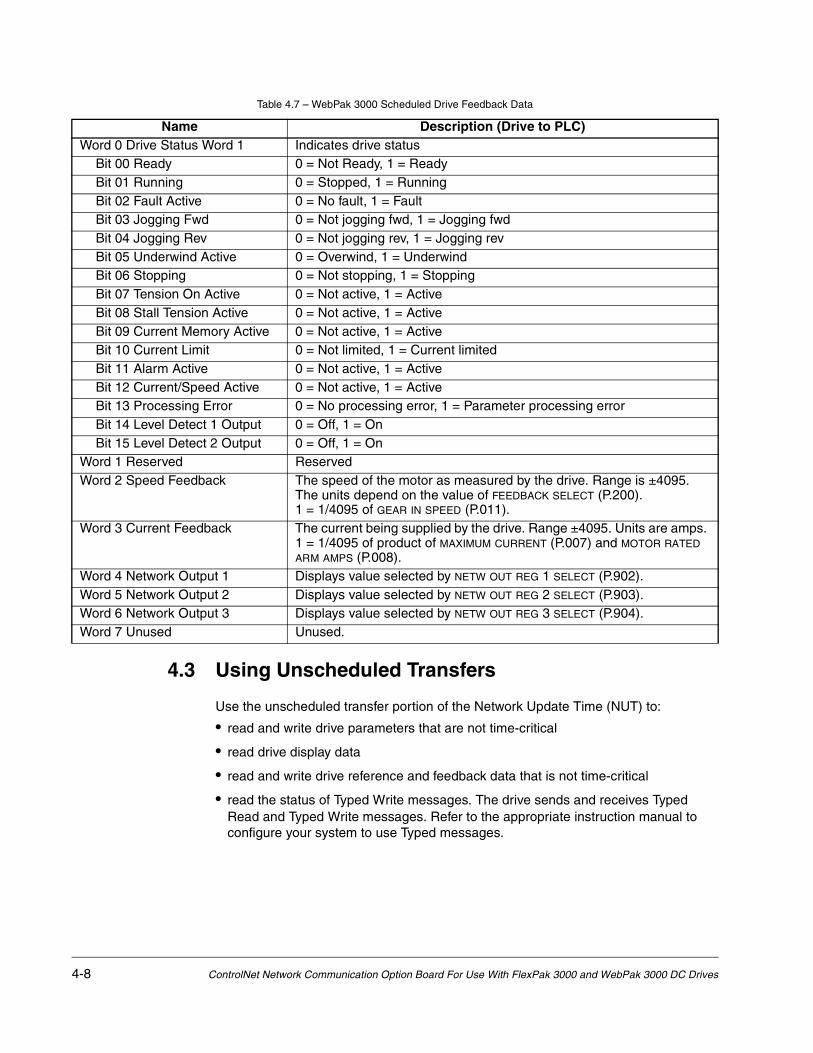
4.3 Using Unscheduled Transfers
Use the unscheduled transfer portion of the Network Update Time (NUT) to:
• read and write drive parameters that are not time-critical
• read drive display data
• read and write drive reference and feedback data that is not time-critical
• read the status of Typed Write messages. The drive sends and receives Typed Read and Typed Write messages. Refer to the appropriate instruction manual to configure your system to use Typed messages.
Table 4.7 – WebPak 3000 Scheduled Drive Feedback Data
Name Description (Drive to PLC)Word 0 Drive Status Word 1 Indicates drive status
Bit 00 Ready 0 = Not Ready, 1 = ReadyBit 01 Running 0 = Stopped, 1 = RunningBit 02 Fault Active 0 = No fault, 1 = FaultBit 03 Jogging Fwd 0 = Not jogging fwd, 1 = Jogging fwdBit 04 Jogging Rev 0 = Not jogging rev, 1 = Jogging revBit 05 Underwind Active 0 = Overwind, 1 = UnderwindBit 06 Stopping 0 = Not stopping, 1 = StoppingBit 07 Tension On Active 0 = Not active, 1 = ActiveBit 08 Stall Tension Active 0 = Not active, 1 = ActiveBit 09 Current Memory Active 0 = Not active, 1 = ActiveBit 10 Current Limit 0 = Not limited, 1 = Current limitedBit 11 Alarm Active 0 = Not active, 1 = ActiveBit 12 Current/Speed Active 0 = Not active, 1 = ActiveBit 13 Processing Error 0 = No processing error, 1 = Parameter processing errorBit 14 Level Detect 1 Output 0 = Off, 1 = OnBit 15 Level Detect 2 Output 0 = Off, 1 = On
Word 1 Reserved ReservedWord 2 Speed Feedback The speed of the motor as measured by the drive. Range is ±4095.
The units depend on the value of FEEDBACK SELECT (P.200). 1 = 1/4095 of GEAR IN SPEED (P.011).
Word 3 Current Feedback The current being supplied by the drive. Range ±4095. Units are amps. 1 = 1/4095 of product of MAXIMUM CURRENT (P.007) and MOTOR RATED ARM AMPS (P.008).
Word 4 Network Output 1 Displays value selected by NETW OUT REG 1 SELECT (P.902).Word 5 Network Output 2 Displays value selected by NETW OUT REG 2 SELECT (P.903).Word 6 Network Output 3 Displays value selected by NETW OUT REG 3 SELECT (P.904).Word 7 Unused Unused.

Programming the Drive 4-9
4.3.1 About MSG Instruction Timing
When a Typed Read message is sent to the drive, the response is returned in under 20 ms. When a Typed Write message is sent to the drive, the message is first processed by the drive. Therefore, up to 600 ms may elapse before the response is returned. These times are applicable only when the network update time and unscheduled traffic bandwidth are not limiting factors.
4.3.2 About the Files You Can Access
When you send an unscheduled message to the drive, the data table address you specify for the target device determines what drive information you want to access. The data table address is in the form of:
Nff:eeewhere: N specifies the file type as integer, ff is the file number, and eee is the element number (word).
The network option board supports these file numbers:
• N10 -- Drive parameters (read and write)
• N11 -- Drive display data (read only)
• N12 -- Drive reference and feedback data (read and write)
• N20 -- Status of the most recent write parameter command (read only)
Figure 4.2 shows how the drive information maps to the drive information integer files.
4.3.3 Using the Drive Parameters Data (N10:x)
Beginning at N10:0, the PLC can read from and write to drive parameters. The drive processes these parameters every 500 ms. From N10:1 - N10:06, there is a one-to-one mapping with P.001 - P.006.
Figure 4.1 – Drive Information Map
N11:0-
N11:172
N12:0-
N12:31
N20:0-
N20:273
N10:0-
N10:273
Read/WriteParameters
(500 msupdate)
Drive DisplayData
(100 ms update)
Reference andFeedback Data
(FlexPak: 5 or 10 msupdate; WebPak:
10 ms update)
Write Status(Read Only)
Unscheduled Traffic
Scheduled Traffic
File inDrive
OptionBoard
DriveInformation

4-10 ControlNet Network Communication Option Board For Use With FlexPak 3000 and WebPak 3000 DC Drives
All the parameters may accessed with one message block. Any contiguous subset of the parameters may be changed without sending a new copy of the entire block.
Some of the parameters are marked Config (configuration), meaning that they may only be changed while the drive is stopped. Any attempt to change the value of these parameters while the drive is in a “running” state will result in an error, and the value in the drive will not be changed. For this reason, the configuration parameters are all grouped together after the tunable parameters. (CONTROL SOURCE SELECT (P.000) is located at the start of the Config section, N10:150.) Tunable and configuration parameters are also grouped according to potential frequency of use, from most-used to least-used.
Refer to table 5.1 for a listing of the file N10 parameters for FlexPak 3000 drives. Refer to table 6.1 for a listing of the file N10 parameters for WebPak 3000 drives.
4.3.4 Using the Drive Display Data (N11:x)
The drive display data can be accessed beginning at N11:0. Attempting to write to any of these parameters will cause an error. The drive updates these parameters every 100 ms. Selected speed feedback parameters are updated at the speed loop scan period (FlexPak 3000 drives: 5 ms for a speed regulator, 10 ms for a voltage regulator; WebPak 3000 drives: 10 ms for a speed regulator, 10 ms for a voltage regulator).
Refer to table 5.2 for a listing of the file N11 parameters for FlexPak 3000 drives. Refer to table 6.2 for a listing of the file N11 parameters for WebPak 3000 drives.
4.3.5 Using the Drive Reference and Feedback Data (N12:x)
When scheduled traffic is reduced to transmit only a subset of the drive reference and feedback data, the information that is not transmitted as scheduled data can be accessed in file N12 as unscheduled data. The drive updates this data at the speed loop scan period (FlexPak 3000 drives: 5 ms for a speed regulator, 10 ms for a voltage regulator; WebPak 3000 drives: 10 ms for a speed regulator, 10 ms for a voltage regulator). A message block can be used to read any or all of the data. The Drive Control word and all of the Drive Feedback data are read only when accessed through file N12. All other words accessible through file N12 are read/write.
Refer to table 5.3 for a listing of the file N12 parameters for FlexPak 3000 drives. Refer to table 6.3 for a listing of the file N12 parameters for WebPak 3000 drives.
4.3.6 Using the Write Status (File N20:x) to Troubleshoot a Drive Parameter
You can troubleshoot errors that may occur when you write values to parameters to the drive. When a write command is sent from the PLC to the drive, it is possible that the value may not be accepted because:
• The parameter is read-only
• The parameter is a configuration parameter and the drive is in run or jog
• The value is out of range (less than the minimum or greater than the maximum)

Programming the Drive 4-11
When this occurs, the MSG instruction’s ER coil is set and an error code (=11 or 0B hex) is written into an element in N20 that corresponds to the parameter that was not accepted. For every element in N10:x there is a corresponding element in N20:x. In response to the error coil, the PLC can read N20:x to find out which parameters were not accepted. When parameters are written to, only the corresponding status words are updated. If a valid value is written, the corresponding element in N20:x is cleared (= 0).
See table 7.1 for the error codes that the drive will return to the PLC when a Typed Read or Typed Write message fails.

4-12 ControlNet Network Communication Option Board For Use With FlexPak 3000 and WebPak 3000 DC Drives
Configuring ControlLogix Applications 5-1
CHAPTER 5Configuring ControlLogix Applications
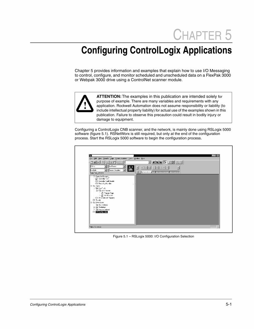
Chapter 5 provides information and examples that explain how to use I/O Messaging to control, configure, and monitor scheduled and unscheduled data on a FlexPak 3000 or Webpak 3000 drive using a ControlNet scanner module.
Configuring a ControlLogix CNB scanner, and the network, is mainly done using RSLogix 5000 software (figure 5.1). RSNetWorx is still required, but only at the end of the configuration process. Start the RSLogix 5000 software to begin the configuration process.
!ATTENTION: The examples in this publication are intended solely for purpose of example. There are many variables and requirements with any application. Rockwell Automation does not assume responsibility or liability (to include intellectual property liability) for actual use of the examples shown in this publication. Failure to observe this precaution could result in bodily injury or damage to equipment.
Figure 5.1 – RSLogix 5000: I/O Configuration Selection

5-2 ControlNet Network Communication Option Board For Use With FlexPak 3000 and WebPak 3000 DC Drives
Step 1. Right-click on the I/O Configuration folder and select New Module (figure 5.2).
Step 2. Select the ControlNet module used by the controller. In this example (figure 5.3), a 1756-CNB Series B ControlNet Bridge is selected.Click OK.
Figure 5.2 – RSLogix 5000: New Module Selection
Figure 5.3 – Select Module Type: 1756-CNB/B Selection

Configuring ControlLogix Applications 5-3
Step 3. Enter a Name, Slot number, and Revision number (figure 5.4). Click Next>.
Step 4. This step is used to define controller-to-module behavior (figure 5.5). Inhibit Module inhibits/un-inhibits the connection to the module. The Major Fault check-box selects if a failure on the connection of this module causes a major fault on the controller if the connection for the module fails. Click Next>.
Figure 5.4 – Module Properties: Name Selection
Figure 5.5 – Module Properties: Controller-to-Module Behavior Screen

5-4 ControlNet Network Communication Option Board For Use With FlexPak 3000 and WebPak 3000 DC Drives
Step 5. This window (figure 5.6) is displayed for informational purposes only. Click Next>.
Step 6. This window (figure 5.7) is displayed for informational purposes only. Click Finish>>.
Figure 5.6 – Module Properties: Identification/Status Screen
Figure 5.7 – Module Properties: Informational Screen

Configuring ControlLogix Applications 5-5
Step 7. The 1756-CNB/B now appears in the I/O Configuration folder (figure 5.8).
Step 8. Right-click on the 1756-CNB and select New Module (figure 5.9).
Figure 5.8 – RSLogix 5000: I/O Configuration Folder
Figure 5.9 – RSLogix 5000: New Module Selection Screen
5-6 ControlNet Network Communication Option Board For Use With FlexPak 3000 and WebPak 3000 DC Drives
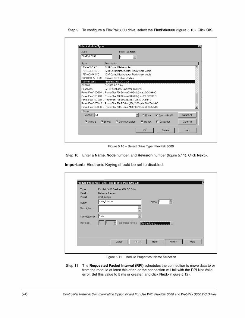
Step 9. To configure a FlexPak3000 drive, select the FlexPak3000 (figure 5.10). Click OK.
Step 10. Enter a Name, Node number, and Revision number (figure 5.11). Click Next>.
Important: Electronic Keying should be set to disabled.
Step 11. The Requested Packet Interval (RPI) schedules the connection to move data to or from the module at least this often or the connection will fail with the RPI Not Valid error. Set this value to 5 ms or greater, and click Next> (figure 5.12).
Figure 5.10 – Select Drive Type: FlexPak 3000
Figure 5.11 – Module Properties: Name Selection
Configuring ControlLogix Applications 5-7
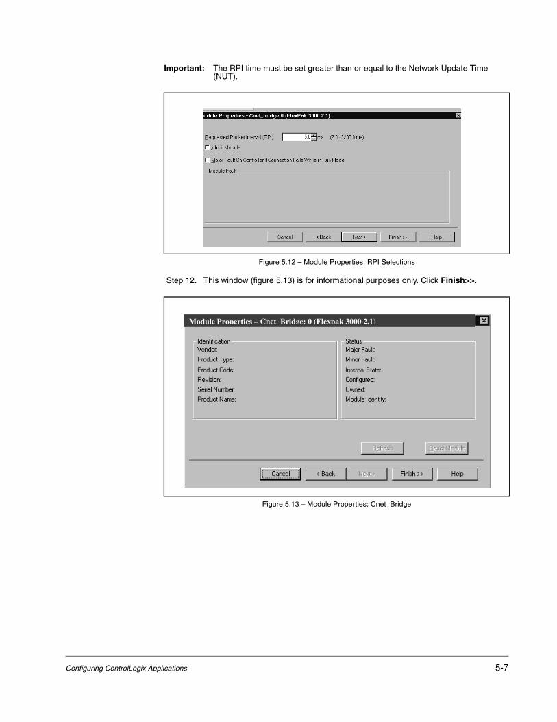
Important: The RPI time must be set greater than or equal to the Network Update Time (NUT).
Step 12. This window (figure 5.13) is for informational purposes only. Click Finish>>.
Figure 5.12 – Module Properties: RPI Selections
Figure 5.13 – Module Properties: Cnet_Bridge
Module Properties – Cnet Bridge: 0 (Flexpak 3000 2.1)

5-8 ControlNet Network Communication Option Board For Use With FlexPak 3000 and WebPak 3000 DC Drives
Step 13. The configured node (“FlexPak 3000” in this example) now appears under the 1756-CNB module in the I/O Configuration folder.
Step 14. Repeat the previous steps for each additional node you need to configure.
Step 15. In the Data Types folder, click on the Module-Defined sub-folder. When you create a module, module-defined data types and tags are automatically created. These tags allow you to access the Input and Output Data of the module via the controller’s ladder logic.
Figure 5.14 – RSLogix: Configure Additional Nodes Screen
Figure 5.15 – RSLogix 5000: Module-Defined Screen

Configuring ControlLogix Applications 5-9
Step 16. Select Communications / Download to download the configuration to the controller (figure 5.16). RSLogix automatically enters on-line mode when complete.
Step 17. An Attention symbol is located next to the Node 2 (FP3000) icon in figure 5.17, which indicates the ControlNet scanner needs to be configured.
Step 18. Start RSNetWorx and perform the following:
a. Click the On-line icon and browse the network.
b. Select Edits Enabled and view the messages in the Message View for completion (figure 5.18). The icon should disappear from the nodes in the Graphical View.
c. Select File / Save and save the project.
d. Close RSNetworx.
This schedules the I/O that was configured in the RSLogix 5000.
Figure 5.16 – Download to the Controller Dialog Box
Figure 5.17 – RSLogix: Attention Symbol
Cnet_bridge:0 (FlexPak 3000 2.1)

5-10 ControlNet Network Communication Option Board For Use With FlexPak 3000 and WebPak 3000 DC Drives
Step 19. The Attention symbol on the RSLogix 5000 connection tree will disappear if the network has been configured properly. You are now ready to develop your ladder logic program.
Figure 5.18 – RSNetWorx for ControlNet Screen

Configuring SLC500 Applications 6-1
CHAPTER 6Configuring SLC500 Applications
Chapter 6 describes how to configure a SLC500 PLC on a ControlNet network with a FlexPak3000 or Webpak3000 drive.
Both the 1747-SCNR and 1747-KFC15 modules are required to communicate fully with a drive and both must be configured as drops on the ControlNet network. If the application only calls for access to Drive Reference and Feedback Data (such as Drive Control and Status Words), and does not call for access to any N10, N11, or N12 drive parameters, the 1747-KFC card will not be required. However, Unscheduled Messaging will not be possible and another connection option to the processor will be required for downloading the required ladder logic.
The examples in this chapter reference a FlexPak3000 drive. A similar process can be followed if your application uses a Webpak3000 drive with the appropriate ControlNet Options Board. Your rack configuration for the Webpak3000 may be different then the included examples. Adjust the examples to match your Nodes and Slots accordingly.
This chapter is intended for use by personnel familiar with the installation and operation of the Reliance Drive and the installation, programming, I/O configuration and operation of the SLC processor using RSLinx, RSLogix 5000 and RSNetWorx for ControlNet software. Personnel should also be familiar with the system configuration documentation.
6.1 Required Software and Equipment
Software and equipment required for configuring a SLC500 on a ControlNet network is listed in table 6.1.
Table 6.1 – Required Software and Equipment
Equipment Description Version
RSLinx Software Version 2.20 or later
RSNetWorx for ControlNet software Version 2.25 or later
RSLogix 500 software Version 3.01 or later
SLC 500 Chassis w/appropriately sized Power Supply
SLC 5/03 processor (1747-L532) or SLC 5/04 processor
OS 301 or higherAny OS
ControlNet Scanner Module: 1747-SCNR
ControlNet RS-232 Interface: 1747-KFC15
PC with 1784-KXTC15 or 1784-PCIC interface card
Flexpak3000/Webpak3000 ControlNet Communications Board (915FK2101)
Version 2.20 or later

6-2 ControlNet Network Communication Option Board For Use With FlexPak 3000 and WebPak 3000 DC Drives
6.2 Network Configuration
Configure the ControlNet network using RSLinx and RSNetWorx for ControlNet software.
Using the parameters suggested in chapter 4 of this manual, configure scheduled traffic with RSNetWorx, by doing a scanlist configuration of the 1747-SCNR module to the drive. It is recommended that Input and Output files are used instead of M1 and M0 files, as discrete I/O is more appropriate for critical data transfer. Make sure keyswitch is in “program” position before download of configuration.
Input address should be [ I:x:y ] with x = slot of SCNR module and y = 1 or greater. Output address should be [ O:x:y ] with x = slot of SCNR module and y = 1 or greater.
Input and Output size for Flexpak3000 and Webpak3000 drives = 8.
Important: Any address offset is limited by 31 words maximum minus the drive I/O word size.
Figure 6.1 – Network Configuration: Connection Properties

Configuring SLC500 Applications 6-3
6.3 1747-KFC15 Set Up
Unlike PLC5 or ControlLogix controllers, the unscheduled messages between the SLC controller and the drive must pass through the KFC15 module and the serial cable, included with the KFC15 module, that physically connects the module and the processor.
Important: ControlNet unscheduled messaging is not fully deterministic and may be further limited by the baud rate selected for Channel 0 (RS232/DF1) communications.
The communication parameters between the SLC500 and the KFC15 must be identical. Set the DIP switches on the KFC15 according to the application. In most cases, choose all default settings. However, the value 19200 is preferable over the default value (1200) for Serial Port Baud Rate.
In RSLogix5000, choose Channel Configuration in the project tree and verify that the “General” and “Chan 0-System” parameters are the same as you set on the KFC15 DIP switches.
Figure 6.2 – Channel Configuration: Chan 0-System

6-4 ControlNet Network Communication Option Board For Use With FlexPak 3000 and WebPak 3000 DC Drives
In the project tree, choose Controller Properties and Controller Communications. Set the appropriate Driver, Node and Path for Communications. The Node and Path must be the ControlNet Mode of the 1747-KFC15 module. After applying all settings, download to the processor.
Figure 6.3 – Controller Properties: Controller Communications
Figure 6.4 – 1747-KFC15 Set Up

Configuring SLC500 Applications 6-5
6.4 Scheduled Messaging (I/O)
To use scheduled messaging, the Ladder Logic must include a line that sets a bit in the SCNR module. The processor must be in run or remote run. Include a line that has a coil that sets word 0, bit 10 in the SCNR module. [O:x:0/10], where x = the slot number where the SCNR module resides. Output word “0” is the SCNR command word. Input word “0” is the SCNR status word.
In the example below:
• O:3.3 had been set up as the output address and I:3.3 had been set up as the input address. There is a four (4) word offset in the discrete I/O Input. The drive appears to the processor as an IO rack with several modules, causing the Input offset.
• O:3.3 (Output register of the SCNR, word 3) shows the Word 0 - Drive Control Word. It is set to 3, meaning bits 00 and 01 (Run and Stop Not) are asserted and the drive is running. O:3.4 is Word 1 - Speed/Torque Reference. It shows the drive reference at 50% full speed. O:3.5 is Word 2 - Field Reference. If a Flexpak3000 is using a field current regulator kit option, this parameter must be set high enough to prevent a drive Field Loss Fault.
• I:3.7 is Word 0 - Drive Status Word (shown in decimal). Individual bits could be used for programming information. I:3.8 is Word 1 - Speed Feedback, which closely follows Output Speed Reference.
Figure 6.5 – Scheduled Messaging Example 1a

6-6 ControlNet Network Communication Option Board For Use With FlexPak 3000 and WebPak 3000 DC Drives
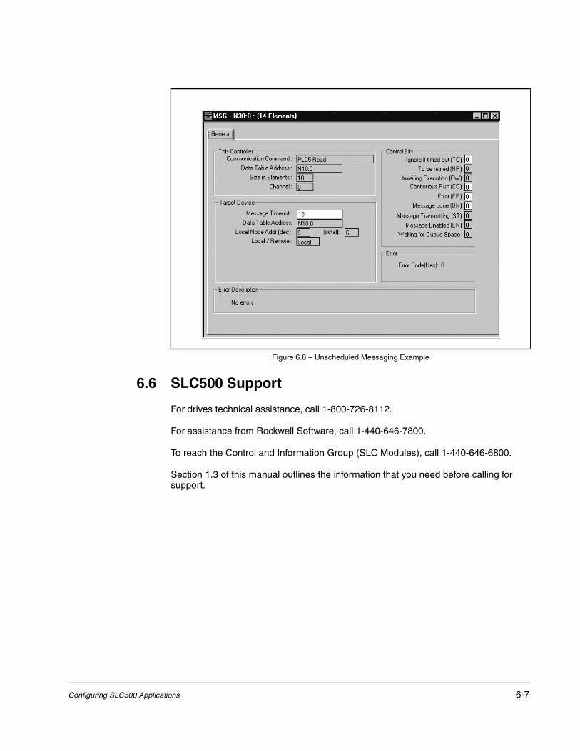
6.5 Unscheduled Messaging
Unscheduled communications must use PLC5 Typed Read and Write messages.
In the example below, drive (Cnet mode 6) parameters at file address N10:0 through N10:9 are read into the controller registers N10:0 through N10:9.
Important: For each message, the element size may not exceed the processor limit of 103 elements.
Figure 6.6 – Scheduled Messaging Example 1b
Figure 6.7 – Unscheduled Messaging Setup Screen
Configuring SLC500 Applications 6-7
6.6 SLC500 Support
For drives technical assistance, call 1-800-726-8112.
For assistance from Rockwell Software, call 1-440-646-7800.
To reach the Control and Information Group (SLC Modules), call 1-440-646-6800.
Section 1.3 of this manual outlines the information that you need before calling for support.
Figure 6.8 – Unscheduled Messaging Example

6-8 ControlNet Network Communication Option Board For Use With FlexPak 3000 and WebPak 3000 DC Drives

Register Map for FlexPak 3000 Drives 7-1
CHAPTER 7Register Map for
FlexPak 3000 Drives
Table 7.1 – File N10:x (Drive Read/Write Parameters) for FlexPak 3000 Drives
File Address Parameter Name
Parameter Number Type Scale
N10:0 Reserved --- Tunable Reserved
N10:1 ACCELERATION TIME P.001 Tunable 1 = 0.1 s
N10:2 DECELERATION TIME P.002 Tunable 1 = 0.1 s
N10:3 MINIMUM SPEED P.003 Tunable 1 = 1 RPM
N10:4 MAXIMUM SPEED P.004 Tunable 1 = 1 RPM
N10:5 POSITIVE CURRENT LIM P.005 Tunable 1 = 1% of MOTOR RATED ARM AMPS (P.008)
N10:6 NEGATIVE CURRENT LIM P.006 Tunable 1 = 1% of MOTOR RATED ARM AMPS (P.008)
N10:7 S-CURVE ROUNDING P.014 Tunable 1 = 1%
N10:8 IR COMPENSATION P.206 Tunable 1 = 1%
N10:9 CURRENT COMPOUNDING P.209 Tunable 1 = 1%
N10:10 AUTO MODE MIN BYPASS P.111 Tunable 0 = OFF, 1 = ON
N10:11 AUTO MODE RAMP BYPASS P.112 Tunable 0 = OFF, 1 = ON
N10:12 NORMALIZED INERTIA P.222 Tunable 1 = 0.01 s
N10:13 CML PI PROP GAIN P.301 Tunable 1 = 0.001
N10:14 CML PI LEAD FREQUENCY P.302 Tunable 1 = 1 rad/s
N10:15 CML REF RATE LIMIT P.303 Tunable 1 = 1 ms
N10:16 SPD LOOP PI PROP GAIN P.211 Tunable 1 = 0.01
N10:17 SPD LOOP PI LEAD FREQ P.212 Tunable 1 = 0.01 rad/s
N10:18 SPD LEADLAG RATIO P.213 Tunable
N10:19 SPD LEADLAG LOW FREQ P.214 Tunable 1 = 0.01 rad/s
N10:20 SPD LOOP LAG FREQ P.215 Tunable 1 = 0.01 rad/s
N10:21 SPD LEADLAG SELECT P.216 Tunable 0 = LEAD/LAG 1 = BYPASS 2 = LAG/LEAD
N10:22 SPD LOOP LAG BYPASS P.217 Tunable 0 = OFF, 1 = ON
N10:23 CML FEEDBACK GAIN ADJ P.300 Tunable 1 = 0.001
N10:24 OCL LEADLAG SELECT P.805 Tunable 0 = LEAD/LAG
1 = BYPASS
2 = LAG/LEAD
N10:25 OCL LEADLAG LOW FREQ P.806 Tunable 1 = 0.01 rad/s
N10:26 OCL LEADLAG RATIO P.807 Tunable

7-2 ControlNet Network Communication Option Board For Use With FlexPak 3000 and WebPak 3000 DC Drives
N10:27 OCL PI PROP GAIN P.808 Tunable 1 = 0.01
N10:28 OCL PI LEAD FREQ P.809 Tunable 1 = 0.01 rad/s
N10:29 OCL PI POSITIVE LIMIT P.810 Tunable 1 = 1% of TOP SPEED (P.011)
N10:30 OCL PI NEGATIVE LIMIT P.811 Tunable 1 = 1% of TOP SPEED ( P.011)
N10:31 OCL TRIM RANGE P.812 Tunable 1 = 1% of TOP SPEED (P.011)
N10:32 OCL REFERENCE SELECT P.800 Tunable 0 = REGISTER 1 = ANALOG IN 12 = ANALOG IN 2 3 = FREQUENCY IN4 = NETW IN REG 1 5 = NETW IN REG 26 = NETW IN REG 3
N10:33 OCL REF REGISTER P.801 Tunable 1 = 1/4095
N10:34 OCL REF RAMP TIME P.802 Tunable 1 = 0.1 s
N10:35 OCL REF ROUNDING P.803 Tunable 1 = 1%
N10:36 ENHANCED FLD VOLT ADJ P.500 Tunable
N10:37 FIELD ECONOMY DELAY P.501 Tunable 1 = 1 min
N10:38 FIELD ECONOMY REF P.511 Tunable 1 = 1% of MOTOR HOT FLD AMPS (P.510)
N10:39 FIELD REF REGISTER P.513 Tunable 1 = 1/4095 of MOTOR HOT FLD AMPS (P.510)
N10:40 FIELD PI PROP GAIN P.514 Tunable 1 = 0.01
N10:41 FIELD PI LEAD FREQ P.515 Tunable 1 = 0.01 rad/s
N10:42 FLD FEEDBACK GAIN ADJ P.516 Tunable 1 = 0.001
N10:43 FLD WEAKEN THRESHOLD P.518 Tunable 1 = 1/4095 MOTOR RATED ARM VOLTS (P.009)
N10:44 FLD WEAKEN PROP GAIN P.519 Tunable 1 = 0.01
N10:45 FLD WEAKEN LEAD FREQ P.520 Tunable 1 = 0.01
N10:46 NETW COMM LOSS SELECT P.901 Tunable 0 = FAULT 1 = USE LAST REF 2 = USE TRMBLK REF
3 = USE TRMBLK CNTL
N10:47 NETW OUT REG 1 SELECT P.902 Tunable
N10:48 NETW OUT REG 2 SELECT P.903 Tunable
N10:49 NETW OUT REG 3 SELECT P.904 Tunable
N10:50 RAMP STOP DECEL TIME P.018 Tunable 1 = 0.1 s
N10:51 STOP SPEED THRESHOLD P.113 Tunable 1 = 1 RPM
N10:52 STOP MODE SELECT P.114 Tunable 0 = RAMP
1 = CURRENT LIMIT
2 = COAST/DB
N10:53 JOG SPEED 1 P.012 Tunable 1 = 1 RPM
N10:54 JOG SPEED 2 P.017 Tunable 1 = 1 RPM
N10:55 JOG ACCEL/DECEL TIME P.013 Tunable 1 = 0.1 s
N10:56 TRIM REF REGISTER P.107 Tunable 1 = 0.1%
Table 7.1 – File N10:x (Drive Read/Write Parameters) for FlexPak 3000 Drives (Continued)
File Address Parameter Name
Parameter Number Type Scale

Register Map for FlexPak 3000 Drives 7-3
N10:57 TRIM REFERENCE SELECT P.108 Tunable 0 = REGISTER
1 = ANALOG MANUAL
2 = ANALOG IN 1 3 = NETW IN REG 14 = NETW IN REG 2 5 = NETW IN REG 36 = ANALOG IN 2
N10:58 TRIM RANGE P.109 Tunable 1 = 0.1%
N10:59 TRIM MODE SELECT P.110 Tunable 0 = NO TRIM 1 = INCREMENTAL 2 = PROPORTIONAL
N10:60 MOP ACCEL TIME P.115 Tunable 1 = 0.1 s
N10:61 MOP DECEL TIME P.120 Tunable 1 = 0.1 s
N10:62 PRESET SPEED 1 P.117 Tunable 1 = 1 RPM
N10:63 PRESET SPEED 2 P.118 Tunable 1 = 1 RPM
N10:64 PRESET SPEED 3 P.119 Tunable 1 = 1 RPM
N10:65 ANALOG TACH GAIN ADJ P.201 Tunable 1 = 0.001
N10:66 ANALOG TACH ZERO ADJ P.202 Tunable
N10:67 ARM VOLTAGE GAIN ADJ P.204 Tunable 1 = 0.001
N10:68 ARM VOLTAGE ZERO ADJ P.205 Tunable
N10:69 ANLG AUTO GAIN ADJ P.101 Tunable 1 = 0.001
N10:70 ANLG AUTO ZERO ADJ P.102 Tunable
N10:71 ANLG MAN REF GAIN ADJ P.104 Tunable 1 = 0.001
N10:72 ANLG MAN REF ZERO ADJ P.105 Tunable
N10:73 ANLG IN 1 GAIN ADJ P.415 Tunable 1 = 0.001
N10:74 ANLG IN 1 ZERO ADJ P.414 Tunable
N10:75 ANLG IN 2 GAIN ADJ P.417 Tunable 1= 0.001
N10:76 ANLG IN 2 ZERO ADJ P.416 Tunable
N10:77 METER OUT 1 GAIN ADJ P.400 Tunable 1= 0.001
N10:78 METER OUT 1 ZERO ADJ P.402 Tunable
Table 7.1 – File N10:x (Drive Read/Write Parameters) for FlexPak 3000 Drives (Continued)
File Address Parameter Name
Parameter Number Type Scale

7-4 ControlNet Network Communication Option Board For Use With FlexPak 3000 and WebPak 3000 DC Drives
N10:79 METER OUT 1 SELECT P.404 Tunable 0 = CML FEEDBACK 1 = CML REFERENCE
2 = CML ERROR 3 = SPD LOOP FEEDBACK
4 = SPD LOOP REFERENCE 5 = SPD LOOP ERROR
6 = SPD LOOP OUTPUT 7 = SPEED RAMP OUTPUT
8 = SPEED RAMP INPUT TP 9 = SPD SOURCE SELECT OUT
10 = TRIM OUTPUT 11 = ARMATURE VOLTAGE 12 = ANALOG TACH FEEDBACK 13 = PULSE TACH FEEDBACK 14 = ZERO 15 = FULL SCALE
16 = POWER OUTPUT 17 = OCL REFERENCE
18 = OCL RAMP OUTPUT 19 = OCL FEEDBACK
20 = OCL OUTPUT 21 = FIELD REFERENCE
22 = FIELD FEEDBACK 23 = NETW IN REG 124 = NETW IN REG 2 25 = NETW IN REG 3
N10:80 METER OUT 2 GAIN ADJ P.401 Tunable 1 = 0.001
N10:81 METER OUT 2 ZERO ADJ P.403 Tunable
Table 7.1 – File N10:x (Drive Read/Write Parameters) for FlexPak 3000 Drives (Continued)
File Address Parameter Name
Parameter Number Type Scale

Register Map for FlexPak 3000 Drives 7-5
N10:82 METER OUT 2 SELECT P.405 Tunable 0 = CML FEEDBACK 1 = CML REFERENCE 2 = CML ERROR 3 = SPD LOOP FEEDBACK
4 = SPD LOOP REFERENCE 5 = SPD LOOP ERROR
6 = SPD LOOP OUTPUT 7 = SPEED RAMP OUTPUT
8 = SPEED RAMP INPUT TP 9 = SPD SOURCE SELECT OUT
10 = TRIM OUTPUT 11 = ARMATURE VOLTAGE 12 = ANALOG TACH FEEDBACK 13 = PULSE TACH FEEDBACK 14 = ZERO 15 = FULL SCALE
16 = POWER OUTPUT 17 = OCL REFERENCE
18 = OCL RAMP OUTPUT 19 = OCL FEEDBACK
20 = OCL OUTPUT 21 = FIELD REFERENCE
22 = FIELD FEEDBACK 23 = NETW IN REG 124 = NETW IN REG 2 25 = NETW IN REG 3
N10:83 ANLG OUT 1 GAIN ADJ P.420 Tunable 1 = 0.001
N10:84 ANLG OUT 2 GAIN ADJ P.422 Tunable 1 = 0.001
N10:85 LEVEL DETECT 1 THRESH P.603 Tunable 1 = 0.1% of selected source
N10:86 LEVEL DETECT 1 DELAY P.604 Tunable 1 = 0.1 s
N10:87 LEVEL DETECT 2 THRESH P.606 Tunable 1 = 0.1% of selected source
N10:88 LEVEL DETECT 2 DELAY P.607 Tunable 1 = 0.1 s
N10:89 PLL MAXIMUM ERROR P.308 Tunable 1 = 1 µsec
N10:90 TACH LOSS SCR ANGLE P.608 Tunable 1 = 1 deg
N10:91 TACH LEAD FLT THRESH P.227 Tunable 1 = 0.1% of TOP SPEED (P.011)
N10:92 TACH LEAD FLT DELAY P.228 Tunable 1 = 1 ms
N10:93 SELF TUNE FIELD RANGE P.218 Tunable 1 = 0.01
N10:94 SELF TUNE STABILITY P.219 Tunable
N10:95 SELF TUNE BRIDGE P.220 Tunable 0 = FORWARD, 1 = REVERSE
N10:96 OPEN SCR SENSITIVITY P.600 Tunable 1 = 1%
N10:97 OPEN SCR TRIP THRESH P.601 Tunable
N10:98 CLOCK FUNCTIONS --- Tunable Read = Elapsed time (hours) since last power upWrite bit 0 = 1 Reset clock to zero; any other value written has no effect.
Table 7.1 – File N10:x (Drive Read/Write Parameters) for FlexPak 3000 Drives (Continued)
File Address Parameter Name
Parameter Number Type Scale

7-6 ControlNet Network Communication Option Board For Use With FlexPak 3000 and WebPak 3000 DC Drives
N10:99 |N10:149
RESERVED --- --- Reserved (future parameter expansion)
N10:150 CONTROL SOURCE SELECT P.000 Config 0 = TERMBLK 1 = KEYPAD 2 = SERIAL 3 = NETWORK
N10:151 CNI PROG/RUN MODE P.915 Config 0 = STOP
1 = USE LAST REF
2 = USE TRMBLK CNTL
N10:152 MOTOR RATED ARM AMPS P.008 Config 1 = 0.1 amp
N10:153 MOTOR RATED ARM VOLTS P.009 Config 1 = 1 volt
N10:154 MAXIMUM CURRENT P.007 Config 1 = 1% of MOTOR RATED ARM AMPS (P.008)
N10:155 CML REF LIMIT SELECT P.311 Config 0 = SPD LOOP PI LIMITS, 1 = REGISTER
N10:156 TOP SPEED P.011 Config 1 = 1 RPM
N10:157 REVERSE DISABLE P.015 Config 0 = OFF, 1 = ON
N10:158 MANUAL REF SELECT P.106 Config 0 = ANALOG, 1 = MOP
N10:159 AUTO REFERENCE SELECT P.103 Config 0 = ANALOG, 1 = FREQUENCY IN
N10:160 INERTIA COMP SELECT P.221 Config 0 = NONE 1 = INTERNAL
2 = ANALOG IN 1 3 = ANALOG IN 24 = NETW IN REG 1 5 = NETW IN REG 26 = NETW IN REG 3
N10:161 POS CURRENT LIM SELECT P.223 Config 0 = REGISTER
1 = ANALOG IN 12 = ANALOG IN 2 3 = NETW IN REG 1 4 = NETW IN REG 2 5 = NETW IN REG 3
N10:162 NEG CURRENT LIM SELECT P.224 Config 0 = REGISTER 1 = ANALOG IN 12 = ANALOG IN 2 3 = NETW IN REG 1 4 = NETW IN REG 25 = NETW IN REG 3
N10:163 NEG CUR LIM INV EN P.226 Config 0 = DISABLED, 1 = ENABLED
N10:164 INV FAULT AVOID SEL P.312 Config 0 = DISABLE 1 = FAULT IMMEDIATELY
2 = DELAY BEFORE FAULT
N10:165 FEEDBACK SELECT P.200 Config 0 = ARMATURE VOLT 1 = DC TACH
2 = PULSE TACH 3 = AC TACH
Table 7.1 – File N10:x (Drive Read/Write Parameters) for FlexPak 3000 Drives (Continued)
File Address Parameter Name
Parameter Number Type Scale

Register Map for FlexPak 3000 Drives 7-7
N10:166 ANLG TACH VOLTS/1000 P.203 Config 1 = 0.1 volts/1000 RPM
N10:167 PULSE TACH PPR P.207 Config 1 = 1 PPR
N10:168 PULSE TACH QUADRATURE P.208 Config 0 = OFF, 1 = ON
N10:169 OCL PROP TRIM SELECT P.813 Config 0 = DISABLED, 1 = ENABLED
N10:170 OCL FEEDBACK SELECT P.804 Config 0 = NONE 1 = CML FEEDBACK
2 = ANALOG IN 1 3 = ANALOG IN 24 = SPEED LOOP OUTPUT 5 = ANALOG AUTO REFERENCE
6 = NETW IN REG 17 = NETW IN REG 28 = NETW IN REG 3
N10:171 OCL TYP3 POSN REG P.814 Config 0 = DISABLED, 1 = ENABLED
N10:172 MOTOR HOT FLD AMPS P.510 Config 1 = 0.01 amp
N10:173 FIELD REF SELECT P.521 Config 0 = REGISTER 1 = ANALOG MAN TRIM REF
2 = ANALOG IN 1 3 = ANALOG IN 2
N10:174 FIELD DELTA HIGH LIM P.587 Config 1 = 1 deg
N10:175 FIELD LOSS THRESHOLD P.512 Config 1 = 1% of MOTOR HOT FLD AMPS (P.510)
N10:176 FIELD AUTO WEAKEN P.517 Config 0 = DISABLE, 1 = ENABLE
N10:177 CT TURNS RATIO P.010 Config
N10:178 MOP RESET ENABLE P.116 Config 0 = OFF, 1 = ON
N10:179 JOG OFF DELAY TIME P.121 Config 1 = 0.1 s
N10:180 STOP DECEL SELECT P.122 Config 0 = DECELERATION TIME 1 = RAMP STOP DECEL TIME
N10:181 NOMINAL AC LINE FREQ P.306 Config 1 = 1 Hz
N10:182 NOMINAL AC LINE VOLTS P.307 Config 1 = 1 VAC
N10:183 PHASE LOSS DETECT EN P.609 Config 0 = DISABLE, 1 = ENABLE
N10:184 DIG OUT 1 SELECT P.409 Config 0 = LEVEL DETECT 1 OUTPUT 1 = LEVEL DETECT 2 OUTPUT
2 = IN CURRENT LIMIT 3 = DRIVE READY
4 = NETW COMM STATUS 5 = NETW IN REG 1 (BIT 0)6 = NETW IN REG 2 (BIT 0) 7 = NETW IN REG 3 (BIT 0)
N10:185 DIG OUT 1 CONTACT TYP P.410 Config 0 = NORMAL OPEN 1 = NORMAL CLOSED
Table 7.1 – File N10:x (Drive Read/Write Parameters) for FlexPak 3000 Drives (Continued)
File Address Parameter Name
Parameter Number Type Scale
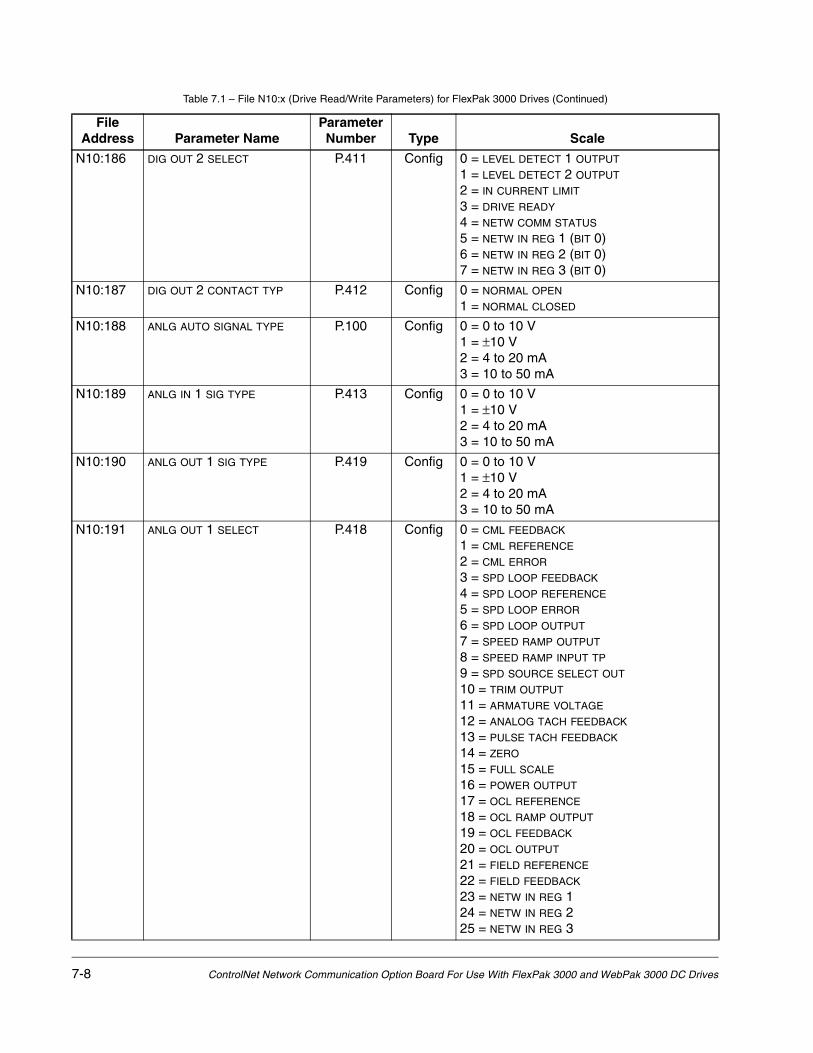
7-8 ControlNet Network Communication Option Board For Use With FlexPak 3000 and WebPak 3000 DC Drives
N10:186 DIG OUT 2 SELECT P.411 Config 0 = LEVEL DETECT 1 OUTPUT 1 = LEVEL DETECT 2 OUTPUT
2 = IN CURRENT LIMIT 3 = DRIVE READY
4 = NETW COMM STATUS 5 = NETW IN REG 1 (BIT 0)6 = NETW IN REG 2 (BIT 0) 7 = NETW IN REG 3 (BIT 0)
N10:187 DIG OUT 2 CONTACT TYP P.412 Config 0 = NORMAL OPEN 1 = NORMAL CLOSED
N10:188 ANLG AUTO SIGNAL TYPE P.100 Config 0 = 0 to 10 V 1 = ±10 V 2 = 4 to 20 mA 3 = 10 to 50 mA
N10:189 ANLG IN 1 SIG TYPE P.413 Config 0 = 0 to 10 V 1 = ±10 V 2 = 4 to 20 mA 3 = 10 to 50 mA
N10:190 ANLG OUT 1 SIG TYPE P.419 Config 0 = 0 to 10 V 1 = ±10 V 2 = 4 to 20 mA 3 = 10 to 50 mA
N10:191 ANLG OUT 1 SELECT P.418 Config 0 = CML FEEDBACK 1 = CML REFERENCE
2 = CML ERROR 3 = SPD LOOP FEEDBACK
4 = SPD LOOP REFERENCE 5 = SPD LOOP ERROR
6 = SPD LOOP OUTPUT 7 = SPEED RAMP OUTPUT
8 = SPEED RAMP INPUT TP 9 = SPD SOURCE SELECT OUT
10 = TRIM OUTPUT 11 = ARMATURE VOLTAGE 12 = ANALOG TACH FEEDBACK 13 = PULSE TACH FEEDBACK 14 = ZERO 15 = FULL SCALE
16 = POWER OUTPUT 17 = OCL REFERENCE
18 = OCL RAMP OUTPUT 19 = OCL FEEDBACK
20 = OCL OUTPUT 21 = FIELD REFERENCE
22 = FIELD FEEDBACK 23 = NETW IN REG 124 = NETW IN REG 2 25 = NETW IN REG 3
Table 7.1 – File N10:x (Drive Read/Write Parameters) for FlexPak 3000 Drives (Continued)
File Address Parameter Name
Parameter Number Type Scale

Register Map for FlexPak 3000 Drives 7-9
N10:192 ANLG OUT 2 SELECT P.421 Config 0 = CML FEEDBACK 1 = CML REFERENCE
2 = CML ERROR 3 = SPD LOOP FEEDBACK
4 = SPD LOOP REFERENCE 5 = SPD LOOP ERROR
6 = SPD LOOP OUTPUT 7 = SPEED RAMP OUTPUT
8 = SPEED RAMP INPUT TP 9 = SPD SOURCE SELECT OUT
10 = TRIM OUTPUT 11 = ARMATURE VOLTAGE 12 = ANALOG TACH FEEDBACK 13 = PULSE TACH FEEDBACK 14 = ZERO 15 = FULL SCALE
16 = POWER OUTPUT 17 = OCL REFERENCE
18 = OCL RAMP OUTPUT 19 = OCL FEEDBACK
20 = OCL OUTPUT 21 = FIELD REFERENCE
22 = FIELD FEEDBACK 23 = NETW IN REG 124 = NETW IN REG 2 25 = NETW IN REG 3
N10:193 FREQ IN ZERO P.423 Config 1 = 1 kHz
N10:194 FREQ IN FULL SCALE P.424 Config 1 = 1 kHz
Table 7.1 – File N10:x (Drive Read/Write Parameters) for FlexPak 3000 Drives (Continued)
File Address Parameter Name
Parameter Number Type Scale

7-10 ControlNet Network Communication Option Board For Use With FlexPak 3000 and WebPak 3000 DC Drives
N10:195 FREQ OUT SELECT P.425 Config 0 = CML FEEDBACK 1 = CML REFERENCE
2 = CML ERROR 3 = SPD LOOP FEEDBACK
4 = SPD LOOP REFERENCE 5 = SPD LOOP ERROR
6 = SPD LOOP OUTPUT 7 = SPEED RAMP OUTPUT
8 = SPEED RAMP INPUT TP 9 = SPD SOURCE SELECT OUT
10 = TRIM OUTPUT 11 = ARMATURE VOLTAGE 12 = ANALOG TACH FEEDBACK 13 = PULSE TACH FEEDBACK 14 = ZERO 15 = FULL SCALE
16 = POWER OUTPUT 17 = OCL REFERENCE
18 = OCL RAMP OUTPUT 19 = OCL FEEDBACK
20 = OCL OUTPUT 21 = FIELD REFERENCE
22 = FIELD FEEDBACK 23 = NETW IN REG 124 = NETW IN REG 2 25 = NETW IN REG 3
N10:196 FREQ OUT ZERO P.426 Config 1 = 1 kHz
N10:197 FREQ OUT FULL SCALE P.427 Config 1 = 1 kHz
N10:198 DIG IN 0 SELECT P.428 Config 0 = BRUSH WEAR INPUT 1 = JOG SPEED SELECT
2 = OCL ENABLE
N10:199 LEVEL DETECT 1 SELECT P.602 Config 0 = CML FEEDBACK 1 = SPD LOOP FEEDBACK
2 = SPD RAMP OUTPUT 3 = SPD RAMP INPUT TP
4 = SPD SOURCE SELECT OUT
N10:200 LEVEL DETECT 2 SELECT P.605 Config 0 = CML FEEDBACK 1 = SPD LOOP FEEDBACK
2 = SPD RAMP OUTPUT 3 = SPD RAMP INPUT TP
4 = SPD SOURCE SELECT OUT
N10:201 Spd Loop Pi Init Sel --- Config 0 = ZERO 1 = SPD LOOP PI INIT VAL
2 = ANALOG MAN TRIM REF
N10:202 |N10:273
Reserved --- --- Reserved (future parameter expansion)
Table 7.1 – File N10:x (Drive Read/Write Parameters) for FlexPak 3000 Drives (Continued)
File Address Parameter Name
Parameter Number Type Scale

Register Map for FlexPak 3000 Drives 7-11
Table 7.2 – File N11:x (Drive Display Data (Read Only)) for FlexPak 3000 Drives
File Address Parameter Name
Parameter Number Description
N11:0 Drive Status Word 1(5 or 10 ms update)
--- b00 Readyb01 Runningb02 Fault b03 Jogging b04 Actual Direction (0 = forward, 1 = reverse)b05 Stopping b06 Mode (0 = Manual, 1 = Auto)b07 At Referenceb08 Alarmb09 Current Limit b10 Parameter Processing Errorb11 Level Detector 1 Outputb12 Level Detector 2 Outputb13 Acceleratingb14 Deceleratingb15 Reserved
N11:1 Drive Status Word 2(5 or 10 ms update)
--- b00 FN/DB Status (0 = open, 1 = closed)b01 Customer Interlock (0 = open, 1 = closed)b02 TB Runb03 TB Direction (0 = forward, 1 = reverse)b04 TB Jog b05 TB Stop (0 = stop, 1 = not stop)b06 Coast/DB Interlock (0 = open, 1 = closed)b07 TB Fault Resetb08 I/O Exp Dig In 1b09 I/O Exp Dig in 2b10 I/O Exp Dig In 3b11 I/O Exp Dig In 4b12 I/O Exp Dig In 5b13 TB Auto/Manual (0 = manual, 1 = auto)b14 Reg Dig In 0b15 Motor Thermostat (0 = open, 1 = closed)
N11:2 SPD LOOP REFERENCE P.295 Final speed loop reference value before the speed regulator
N11:3 SPD LOOP FEEDBACK
(5 or 10 ms update)P.296 Speed loop feedback value, after all conditioning and
scaling
N11:4 SPD LOOP OUTPUT P.299 Speed loop PI value, output to the CML
N11:5 ARMATURE VOLTAGE
(5 or 10 ms update)P.289 Armature voltage value after scaling, before IR
compensation
N11:6 Average CML Feedback --- Current Minor Loop feedback average over last 8 CML scans
N11:7 Network Output Reg 1(5 or 10 ms update)
--- Value of parameter from NETW OUT REG 1 SELECT (P.902)
N11:8 Network Output Reg 2(5 or 10 ms update)
--- Value of parameter from NETW OUT REG 2 SELECT (P.903)

7-12 ControlNet Network Communication Option Board For Use With FlexPak 3000 and WebPak 3000 DC Drives
N11:9 Network Output Reg 3(5 or 10 ms update)
--- Value of parameter from NETW OUT REG 3 SELECT (P.904)
N11:10 NETW IN REG 1 P.905 Present value of Network Input Register 1
N11:11 NETW IN REG 2 P.906 Present value of Network Input Register 2
N11:12 NETW IN REG 3 P.907 Present value of Network Input Register 3
N11:13 Drive Fault Word 1(latched)
--- b00 Line Synchronization Loss b01 Field Current Loss b02 Sustained Overload b03 Self Tune b04 Motor Thermostat b05 Controller Thermostat b06 Blower Motor Starter Open b07 Shorted SCR b08 Instantaneous Overcurrentb09 Overspeed/Overvoltageb10 Open SCRb11 Open Armatureb12 Tachometer Lossb13 OIM Communicationb14 Network Communicationb15 Tracking (reversed tach) Error
N11:14 Drive Fault Word 2(latched)
--- Reserved
N11:15 Drive Alarm Word(latched)
--- b00 Brush wear low b01 AC line voltage low (<90%)b02 AC line voltage high (>115%) b03 Reserved |b15 Reserved
N11:16 Stop Cause Word --- b00 Stop assertedb01 Jog de-asserted for > 1 second b02 Internal stop request b03 Current Limit stop b04 Ramp stop b05 Coast/DB stop b06 Fault stop (or self tune completed) b07 Customer Interlock opened b08 Coast/DB Interlock openedb09 Main contactor openedb10 Reserved |b15 Reserved
N11:17 ANALOG AUTO REFERENCE P.188 Analog Auto mode reference, after scaling
N11:18 TORQUE REFERENCE P.189 Present torque (current) reference value
N11:19 MOP OUTPUT P.191 Present MOP output value
Table 7.2 – File N11:x (Drive Display Data (Read Only)) for FlexPak 3000 Drives (Continued)
File Address Parameter Name
Parameter Number Description

Register Map for FlexPak 3000 Drives 7-13
N11:20 ANALOG MANUAL REFERENCE
P.192 Analog Manual mode reference value, after scaling
N11:21 SPD SOURCE SELECT OUT P.193 Selected speed source value
N11:22 ANALOG MAN TRIM REF P.194 Trim reference value when analog input used for trim
N11:23 DRAW PERCENTAGE OUT P.196 Product of selected trim reference and TRIM RANGE (P.109)
N11:24 TRIM OUTPUT P.197 Present value added to SPD SOURCE SELECT OUT (P.193)
N11:25 SPEED RAMP INPUT TP P.198 Speed reference value immediately before S-curve ramp
N11:26 SPEED RAMP OUTPUT P.199 Speed reference value immediately after S-curve ramp
N11:27 IR COMPENSATION TP P.290 Value subtracted from ARMATURE VOLTAGE (P.289)
N11:28 ANALOG TACH FEEDBACK P.291 Analog tachometer value, after scaling
N11:29 PULSE TACH FEEDBACK P.292 Pulse encoder value, after scaling
N11:30 CURRENT COMPOUND TP P.293 Value subtracted from SPEED RAMP OUTPUT (P.199)
N11:31 JOG RAMP OUTPUT P.294 Jog reference value immediately after jog ramp
N11:32 SPD LOOP ERROR P.297 Difference between SPD LOOP REFERENCE (P.295) and SPD LOOP FEEDBACK (P.296)
N11:33 SPD LOOP LAG OUTPUT P.298 Value immediately after speed loop forward path lag
N11:34 AC LINE VOLTAGE P.392 Measured AC line voltage (RMS value)
N11:35 AC LINE PERIOD P.393 Measured AC line period (µsec)
N11:36 ARMATURE BRIDGE POL P.394 0 = OFF (forward bridge active) 1 = ON (reverse bridge active)
N11:37 J18 ARM I FB RESISTOR P.395 1 = 15 ohm, 2 = 20 ohm, 3 = 30 ohm, 4 = 39 ohm
N11:38 CML REFERENCE P.396 Reference value to the CML after rate and amplitude limiting
N11:39 CML FEEDBACK
(5 OR 10 MS UPDATE)P.397 CML feedback value after conditioning and scaling
N11:40 CML ERROR P.398 Difference between CML REFERENCE (P.396) and CML FEEDBACK (P.397)
N11:41 ARMATURE DELTA P.399 Present armature firing angle, in µsec
N11:42 DIG IN 0 P.490 Digital input 0 (terminal 12 on regulator board); Brush Wear, Jog Speed Select, or OCL Enable
N11:43 FREQ IN P.491 Frequency input (terminals 39, 40, 41 on the I/O Expansion board)
N11:44 ANLG IN 1 P.492 Analog input 1 (terminals 50, 51 on the I/O Expansion board)
N11:45 ANLG IN 2 P.493 Analog input 2 (terminals 52, 53 on the I/O Expansion board)
N11:46 DIG IN 1 P.495 Digital input 1 (terminal 59 on the I/O Expansion board) Preset A
Table 7.2 – File N11:x (Drive Display Data (Read Only)) for FlexPak 3000 Drives (Continued)
File Address Parameter Name
Parameter Number Description
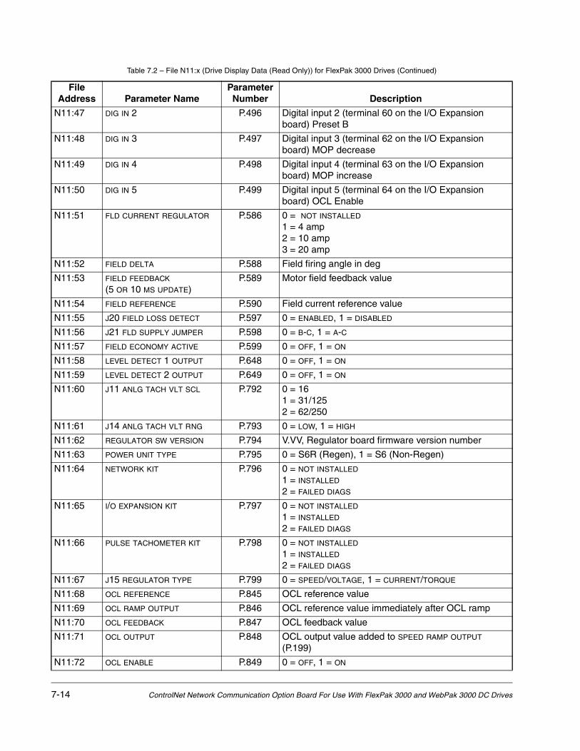
7-14 ControlNet Network Communication Option Board For Use With FlexPak 3000 and WebPak 3000 DC Drives
N11:47 DIG IN 2 P.496 Digital input 2 (terminal 60 on the I/O Expansion board) Preset B
N11:48 DIG IN 3 P.497 Digital input 3 (terminal 62 on the I/O Expansion board) MOP decrease
N11:49 DIG IN 4 P.498 Digital input 4 (terminal 63 on the I/O Expansion board) MOP increase
N11:50 DIG IN 5 P.499 Digital input 5 (terminal 64 on the I/O Expansion board) OCL Enable
N11:51 FLD CURRENT REGULATOR P.586 0 = NOT INSTALLED 1 = 4 amp 2 = 10 amp 3 = 20 amp
N11:52 FIELD DELTA P.588 Field firing angle in deg
N11:53 FIELD FEEDBACK
(5 OR 10 MS UPDATE)P.589 Motor field feedback value
N11:54 FIELD REFERENCE P.590 Field current reference value
N11:55 J20 FIELD LOSS DETECT P.597 0 = ENABLED, 1 = DISABLED
N11:56 J21 FLD SUPPLY JUMPER P.598 0 = B-C, 1 = A-C
N11:57 FIELD ECONOMY ACTIVE P.599 0 = OFF, 1 = ON
N11:58 LEVEL DETECT 1 OUTPUT P.648 0 = OFF, 1 = ON
N11:59 LEVEL DETECT 2 OUTPUT P.649 0 = OFF, 1 = ON
N11:60 J11 ANLG TACH VLT SCL P.792 0 = 16 1 = 31/125 2 = 62/250
N11:61 J14 ANLG TACH VLT RNG P.793 0 = LOW, 1 = HIGH
N11:62 REGULATOR SW VERSION P.794 V.VV, Regulator board firmware version number
N11:63 POWER UNIT TYPE P.795 0 = S6R (Regen), 1 = S6 (Non-Regen)
N11:64 NETWORK KIT P.796 0 = NOT INSTALLED 1 = INSTALLED 2 = FAILED DIAGS
N11:65 I/O EXPANSION KIT P.797 0 = NOT INSTALLED 1 = INSTALLED 2 = FAILED DIAGS
N11:66 PULSE TACHOMETER KIT P.798 0 = NOT INSTALLED 1 = INSTALLED 2 = FAILED DIAGS
N11:67 J15 REGULATOR TYPE P.799 0 = SPEED/VOLTAGE, 1 = CURRENT/TORQUE
N11:68 OCL REFERENCE P.845 OCL reference value
N11:69 OCL RAMP OUTPUT P.846 OCL reference value immediately after OCL ramp
N11:70 OCL FEEDBACK P.847 OCL feedback value
N11:71 OCL OUTPUT P.848 OCL output value added to SPEED RAMP OUTPUT (P.199)
N11:72 OCL ENABLE P.849 0 = OFF, 1 = ON
Table 7.2 – File N11:x (Drive Display Data (Read Only)) for FlexPak 3000 Drives (Continued)
File Address Parameter Name
Parameter Number Description

Register Map for FlexPak 3000 Drives 7-15
N11:73 NETW COMM STATUS P.908 0 = NOT ACTIVE, 1 = ACTIVE
N11:74 NETW TYPE & VERSION P.909 TV.VV:T = Network type 1, 2 = AutoMax, Profibus, InterBus 4 = DeviceNet 5 = ControlNetV.VV = Network board firmware version number
N11:75 NETW DROP NUMBER P.900 Internal network drop number
N11:76 First Fault Code --- Fault code of the first fault that occurred following the last fault reset
N11:77 Fault Log Count --- Number of faults in the fault log
N11:78 Fault Log 0 --- Fault log value 1
N11:79 Fault Log 1 --- Fault log value 2
N11:80 Fault Log 2 --- Fault log value 3
N11:81 Fault Log 3 --- Fault log value 4
N11:82 Fault Log 4 --- Fault log value 5
N11:83 Fault Log 5 --- Fault log value 6
N11:84 Fault Log 6 --- Fault log value 7
N11:85 Fault Log 7 --- Fault log value 8
N11:86 Fault Log 8 --- Fault log value 9
N11:87 Fault Log 9 --- Fault log value 10
N11:88 Last Alarm Code --- Alarm code of the most recent alarm0 = no active alarms
N11:89 Alarm Log Count --- Number of alarms in the alarm log
N11:90 Alarm Log 0 --- Alarm log value 1
N11:91 Alarm Log 1 --- Alarm log value 2
N11:92 Alarm Log 2 --- Alarm log value 3
N11:93 Alarm Log 3 --- Alarm log value 4
N11:94 Alarm Log 4 --- Alarm log value 5
N11:95 Alarm Log 5 --- Alarm log value 6
N11:96 Alarm Log 6 --- Alarm log value 7
N11:97 Alarm Log 7 --- Alarm log value 8
N11:98 Alarm Log 8 --- Alarm log value 9
N11:99 Alarm Log 9 --- Alarm log value 10
N11:100 |N11:172
Reserved --- Reserved
Table 7.2 – File N11:x (Drive Display Data (Read Only)) for FlexPak 3000 Drives (Continued)
File Address Parameter Name
Parameter Number Description

7-16 ControlNet Network Communication Option Board For Use With FlexPak 3000 and WebPak 3000 DC Drives
Table 7.3 – File N12:x (Drive Reference and Feedback Data) for FlexPak 3000 Drives
Drive Reference Data Drive Feedback Data (Read Only)
N12:0 Drive Control Word (Read Only) N12:16 Drive Status Word 1
N12:1 Speed/Torque Reference (R/W) N12:17 Speed Feedback
N12:2 Field Reference (R/W) N12:18 Current Feedback
N12:3 Network Input Reg #1 (R/W) N12:19 Network Output Reg #1
N12:4 Network Input Reg #2 (R/W) N12:20 Network Output Reg #2
N12:5 Network Input Reg #3 (R/W) N12:21 Network Output Reg #3
N12:6 Speed Feedback Gain (R/W) N12:22 Speed Feedback Gain
N12:7 Speed Loop PI Initial Value (R/W) N12:23 Speed Loop PI Initial Value
N12:8 Reserved |N12:15
N12:24 Reserved |N12:31

Register Map for WebPak 3000 Drives 8-1
CHAPTER 8Register Map for
WebPak 3000 Drives
Table 8.1 – File N10:x (Drive Read/Write Parameters) for WebPak 3000 Drives
File Address Parameter Name
Parameter Number Type Scale
N10:0 RESERVED --- Tunable Reserved
N10:1 ACCELERATION TIME P.001 Tunable 1 = 0.1 s
N10:2 DECELERATION TIME P.002 Tunable 1 = 0.1 s
N10:3 MINIMUM SPEED P.003 Tunable 1 = 1 RPM
N10:4 MAXIMUM SPEED P.004 Tunable 1 = 1 RPM
N10:5 POSITIVE CURRENT LIM P.005 Tunable 1 = 1% of MOTOR RATED ARM AMPS (P.008)
N10:6 NEGATIVE CURRENT LIM P.006 Tunable 1 = 1% of MOTOR RATED ARM AMPS (P.008)
N10:7 S-CURVE ROUNDING P.014 Tunable 1 = 1%
N10:8 IR COMPENSATION P.206 Tunable 1 = 1%
N10:9 CURRENT COMPOUNDING P.209 Tunable 1 = 1%
N10:10 MINIMUM SPEED BYPASS P.111 Tunable 0 = OFF, 1 = ON
N10:11 SPEED RAMP BYPASS P.112 Tunable 0 = OFF, 1 = ON
N10:12 LINE SPEED HYSTERESIS P.136 Tunable
N10:13 SYSTEM INERTIA P.222 Tunable 0.01 s
N10:14 CML PI PROP GAIN P.301 Tunable 1 = 0.001
N10:15 CML PI LEAD FREQUENCY P.302 Tunable 1 = 1 rad/s
N10:16 CML REF RATE LIMIT P.303 Tunable 1 = 1 ms
N10:17 SPD LOOP PI PROP GAIN P.211 Tunable 1 = 0.01
N10:18 SPD LOOP PI LEAD FREQ P.212 Tunable 1 = 0.01 rad/s
N10:19 SPD LEADLAG RATIO P.213 Tunable
N10:20 SPD LEADLAG LOW FREQ P.214 Tunable 1 = 0.01 rad/s
N10:21 SPD LOOP LAG FREQ P.215 Tunable 1 = 0.01 rad/s
N10:22 SPD LEADLAG SELECT P.216 Tunable 0 = LEAD/LAG 1 = BYPASS 2 = LAG/LEAD
N10:23 SPD LOOP LAG BYPASS P.217 Tunable 0 = OFF, 1 = ON
N10:24 REF RATE LAG FREQ P.864 Tunable 1 = 0.01 rad/s
N10:25 CURRENT MEMORY BOOST P.313 Tunable 1 = 1%
N10:26 CML FEEDBACK GAIN ADJ P.300 Tunable 1 = 0.001
N10:27 WINDER CORE DIA 1 P.822 Tunable 1 = 1.00 in
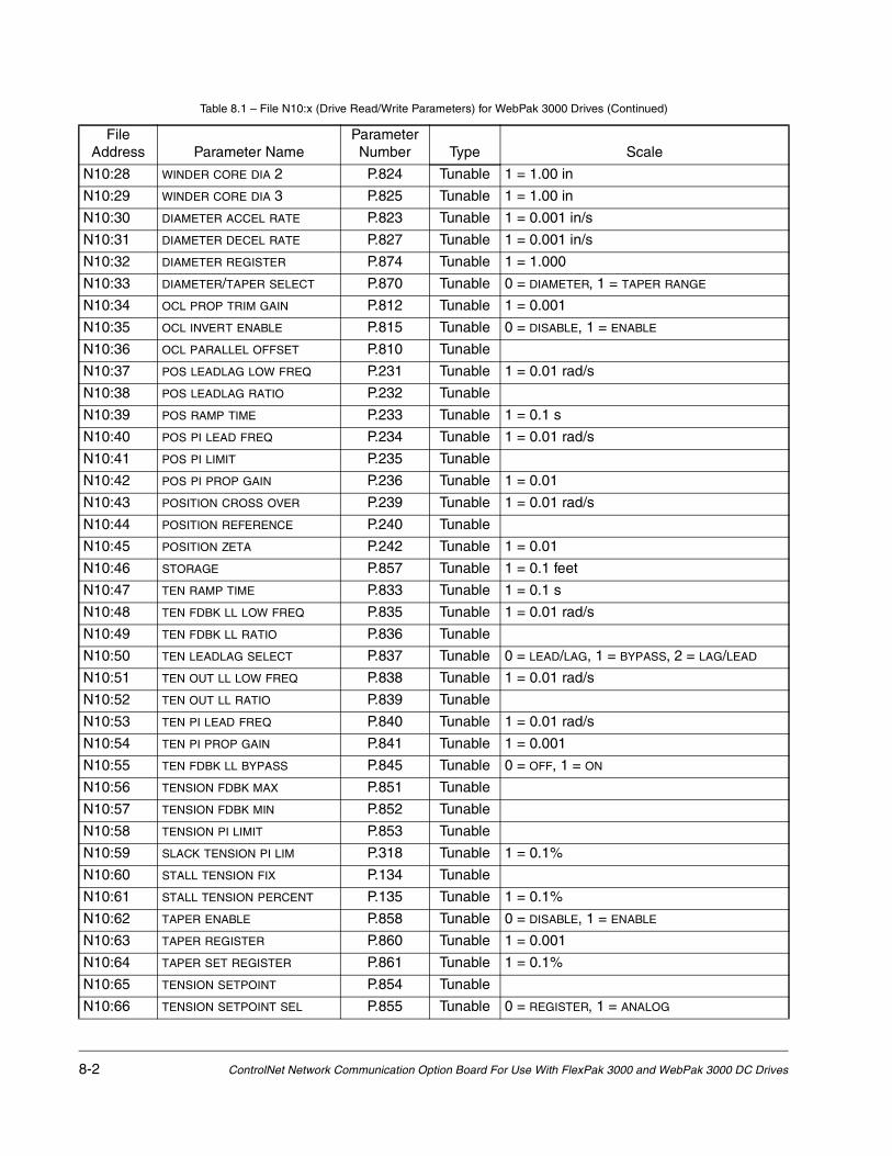
8-2 ControlNet Network Communication Option Board For Use With FlexPak 3000 and WebPak 3000 DC Drives
N10:28 WINDER CORE DIA 2 P.824 Tunable 1 = 1.00 in
N10:29 WINDER CORE DIA 3 P.825 Tunable 1 = 1.00 in
N10:30 DIAMETER ACCEL RATE P.823 Tunable 1 = 0.001 in/s
N10:31 DIAMETER DECEL RATE P.827 Tunable 1 = 0.001 in/s
N10:32 DIAMETER REGISTER P.874 Tunable 1 = 1.000
N10:33 DIAMETER/TAPER SELECT P.870 Tunable 0 = DIAMETER, 1 = TAPER RANGE
N10:34 OCL PROP TRIM GAIN P.812 Tunable 1 = 0.001
N10:35 OCL INVERT ENABLE P.815 Tunable 0 = DISABLE, 1 = ENABLE
N10:36 OCL PARALLEL OFFSET P.810 Tunable
N10:37 POS LEADLAG LOW FREQ P.231 Tunable 1 = 0.01 rad/s
N10:38 POS LEADLAG RATIO P.232 Tunable
N10:39 POS RAMP TIME P.233 Tunable 1 = 0.1 s
N10:40 POS PI LEAD FREQ P.234 Tunable 1 = 0.01 rad/s
N10:41 POS PI LIMIT P.235 Tunable
N10:42 POS PI PROP GAIN P.236 Tunable 1 = 0.01
N10:43 POSITION CROSS OVER P.239 Tunable 1 = 0.01 rad/s
N10:44 POSITION REFERENCE P.240 Tunable
N10:45 POSITION ZETA P.242 Tunable 1 = 0.01
N10:46 STORAGE P.857 Tunable 1 = 0.1 feet
N10:47 TEN RAMP TIME P.833 Tunable 1 = 0.1 s
N10:48 TEN FDBK LL LOW FREQ P.835 Tunable 1 = 0.01 rad/s
N10:49 TEN FDBK LL RATIO P.836 Tunable
N10:50 TEN LEADLAG SELECT P.837 Tunable 0 = LEAD/LAG, 1 = BYPASS, 2 = LAG/LEAD
N10:51 TEN OUT LL LOW FREQ P.838 Tunable 1 = 0.01 rad/s
N10:52 TEN OUT LL RATIO P.839 Tunable
N10:53 TEN PI LEAD FREQ P.840 Tunable 1 = 0.01 rad/s
N10:54 TEN PI PROP GAIN P.841 Tunable 1 = 0.001
N10:55 TEN FDBK LL BYPASS P.845 Tunable 0 = OFF, 1 = ON
N10:56 TENSION FDBK MAX P.851 Tunable
N10:57 TENSION FDBK MIN P.852 Tunable
N10:58 TENSION PI LIMIT P.853 Tunable
N10:59 SLACK TENSION PI LIM P.318 Tunable 1 = 0.1%
N10:60 STALL TENSION FIX P.134 Tunable
N10:61 STALL TENSION PERCENT P.135 Tunable 1 = 0.1%
N10:62 TAPER ENABLE P.858 Tunable 0 = DISABLE, 1 = ENABLE
N10:63 TAPER REGISTER P.860 Tunable 1 = 0.001
N10:64 TAPER SET REGISTER P.861 Tunable 1 = 0.1%
N10:65 TENSION SETPOINT P.854 Tunable
N10:66 TENSION SETPOINT SEL P.855 Tunable 0 = REGISTER, 1 = ANALOG
Table 8.1 – File N10:x (Drive Read/Write Parameters) for WebPak 3000 Drives (Continued)
File Address Parameter Name
Parameter Number Type Scale

Register Map for WebPak 3000 Drives 8-3
N10:67 DANCER ACCEL TIME P.873 Tunable 1 = 0.1 s
N10:68 DANCER DECEL TIME P.819 Tunable 1 = 0.1 s
N10:69 MAX DANCER LOAD P.831 Tunable
N10:70 MIN DANCER LOAD P.832 Tunable
N10:71 FRICTION LOSS P.123 Tunable 1 = 0.1%
N10:72 WINDAGE LOSS P.243 Tunable 1 = 0.1%
N10:73 WIDTH/BUILDUP FACTOR P.872 Tunable 1 = 0.001
N10:74 INERTIA GAIN ACCEL P.245 Tunable 1 = 0.01
N10:75 INERTIA GAIN DECEL P.229 Tunable 1 = 0.01
N10:76 FIELD ECONOMY DELAY P.501 Tunable 1 = 1 min
N10:77 FIELD ECONOMY REF P.511 Tunable 1 = 1% of MOTOR HOT FLD AMPS (P.510)
N10:78 FIELD REF REGISTER P.513 Tunable 1 = 1/4095 of MOTOR HOT FLD AMPS (P.510)
N10:79 FIELD PI PROP GAIN P.514 Tunable 1 = 0.01
N10:80 FIELD PI LEAD FREQ P.515 Tunable 1 = 0.01 rad/s
N10:81 FIELD SHAPING LAG P.538 Tunable 1 = 0.01 rad/s
N10:82 FLD FEEDBACK GAIN ADJ P.516 Tunable 1 = 0.001
N10:83 FLD WEAKEN THRESHOLD P.518 Tunable 1 = 1/4095 of MOTOR RATED ARM VOLTS (P.009)
N10:84 FLD WEAKEN PROP GAIN P.519 Tunable 1 = 0.01
N10:85 FLD WEAKEN LEAD FREQ P.520 Tunable 1 = 0.01 rad/s
N10:86 NETW OUT REG 1 SELECT P.902 Tunable
N10:87 NETW OUT REG 2 SELECT P.903 Tunable
N10:88 NETW OUT REG 3 SELECT P.904 Tunable
N10:89 RAMP STOP DECEL TIME P.018 Tunable 1 = 0.1 s
N10:90 STOP SPEED THRESHOLD P.113 Tunable 1 = 1 RPM (or user-defined units)
N10:91 STOP MODE SELECT P.114 Tunable 0 = RAMP
1 = CURRENT LIMIT
2 = COAST/DB
N10:92 JOG SPEED P.012 Tunable 1 = 1 FPM
N10:93 JOG ACCEL/DECEL TIME P.013 Tunable 1 = 0.1 s
N10:94 TRIM REF REGISTER P.107 Tunable 1 = 0.1%
N10:95 TRIM REFERENCE SELECT P.108 Tunable 0 = REGISTER
1 = ANALOG
2 = NETW IN REG 13 = NETW IN REG 24 = NETW IN REG 3
N10:96 TRIM RANGE P.109 Tunable 1 = 0.1%
N10:97 TRIM MODE SELECT P.110 Tunable 0 = NO TRIM
1 = INCREMENTAL
2 = PROPORTIONAL
N10:98 ANALOG TACH GAIN ADJ P.201 Tunable 1 = 0.001
Table 8.1 – File N10:x (Drive Read/Write Parameters) for WebPak 3000 Drives (Continued)
File Address Parameter Name
Parameter Number Type Scale
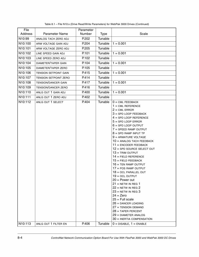
8-4 ControlNet Network Communication Option Board For Use With FlexPak 3000 and WebPak 3000 DC Drives
N10:99 ANALOG TACH ZERO ADJ P.202 Tunable
N10:100 ARM VOLTAGE GAIN ADJ P.204 Tunable 1 = 0.001
N10:101 ARM VOLTAGE ZERO ADJ P.205 Tunable
N10:102 LINE SPEED GAIN ADJ P.101 Tunable 1 = 0.001
N10:103 LINE SPEED ZERO ADJ P.102 Tunable
N10:104 DIAMETER/TAPER GAIN P.104 Tunable 1 = 0.001
N10:105 DIAMETER/TAPER ZERO P.105 Tunable
N10:106 TENSION SETPOINT GAIN P.415 Tunable 1 = 0.001
N10:107 TENSION SETPOINT ZERO P.414 Tunable
N10:108 TENSION/DANCER GAIN P.417 Tunable 1 = 0.001
N10:109 TENSION/DANCER ZERO P.416 Tunable
N10:110 ANLG OUT 1 GAIN ADJ P.400 Tunable 1 = 0.001
N10:111 ANLG OUT 1 ZERO ADJ P.402 Tunable
N10:112 ANLG OUT 1 SELECT P.404 Tunable 0 = CML FEEDBACK
1 = CML REFERENCE
2 = CML ERROR
3 = SPD LOOP FEEDBACK
4 = SPD LOOP REFERENCE
5 = SPD LOOP ERROR
6 = SPD LOOP OUTPUT
7 = SPEED RAMP OUTPUT
8 = SPD RAMP INPUT TP
9 = ARMATURE VOLTAGE
10 = ANALOG TACH FEEDBACK
11 = ENCODER FEEDBACK
12 = SPD SOURCE SELECT OUT
13 = TRIM OUTPUT
14 = FIELD REFERENCE
15 = FIELD FEEDBACK
16 = TEN RAMP OUTPUT
17 = POS RAMP OUTPUT
18 = OCL PARALLEL OUT
19 = OCL OUTPUT
20 = Power out21 = NETW IN REG 122 = NETW IN REG 223 = NETW IN REG 324 = Zero25 = Full scale26 = DANCER LOADING
27 = TENSION DEMAND
28 = TAPER PERCENT
29 = DIAMETER ANALOG
30 = INERTIA COMPENSATION
N10:113 ANLG OUT 1 FILTER EN P.406 Tunable 0 = DISABLE, 1 = ENABLE
Table 8.1 – File N10:x (Drive Read/Write Parameters) for WebPak 3000 Drives (Continued)
File Address Parameter Name
Parameter Number Type Scale

Register Map for WebPak 3000 Drives 8-5
N10:114 ANLG OUT 2 GAIN ADJ P.401 Tunable 1 = 0.001
N10:115 ANLG OUT 2 ZERO ADJ P.403 Tunable
N10:116 ANLG OUT 2 SELECT P.405 Tunable 0 = CML FEEDBACK
1 = CML REFERENCE
2 = CML ERROR
3 = SPD LOOP FEEDBACK
4 = SPD LOOP REFERENCE
5 = SPD LOOP ERROR
6 = SPD LOOP OUTPUT
7 = SPEED RAMP OUTPUT
8 = SPD RAMP INPUT TP
9 = ARMATURE VOLTAGE
10 = ANALOG TACH FEEDBACK
11 = ENCODER FEEDBACK
12 = SPD SOURCE SELECT OUT
13 = TRIM OUTPUT
14 = FIELD REFERENCE
15 = FIELD FEEDBACK
16 = TEN RAMP OUTPUT
17 = POS RAMP OUTPUT
18 = OCL PARALLEL OUT
19 = OCL OUTPUT
20 = Power out21 = NETW IN REG 122 = NETW IN REG 223 = NETW IN REG 324 = Zero25 = Full scale26 = DANCER LOADING
27 = TENSION DEMAND
28 = TAPER PERCENT
29 = DIAMETER ANALOG
30 = INERTIA COMPENSATION
N10:117 ANLG OUT 2 FILTER EN P.407 Tunable 0 = DISABLE, 1 = ENABLE
N10:118 ANLG OUT 3 GAIN ADJ P.420 Tunable 1 = 0.001
N10:119 ANLG OUT 4 GAIN ADJ P.422 Tunable 1 = 0.001
N10:120 LEVEL REGISTER 1 P.603 Tunable
N10:121 LEVEL DETECT 1 DELAY P.604 Tunable 1 = 0.1 S
N10:122 LEVEL REGISTER 2 P.606 Tunable
N10:123 LEVEL DETECT 2 DELAY P.607 Tunable 1 = 0.1 s
N10:124 PLL MAXIMUM ERROR P.308 Tunable 1 = 1 µsec
N10:125 TACH LOSS SCR ANGLE P.608 Tunable 1 = 1 degree
N10:126 TACH LEAD FLT THRESH P.227 Tunable 1 = 0.1% of TOP SPEED (P.011)
N10:127 TACH LEAD FLT DELAY P.228 Tunable 1 = 1 ms
N10:128 SELF TUNE STABILITY P.219 Tunable
Table 8.1 – File N10:x (Drive Read/Write Parameters) for WebPak 3000 Drives (Continued)
File Address Parameter Name
Parameter Number Type Scale

8-6 ControlNet Network Communication Option Board For Use With FlexPak 3000 and WebPak 3000 DC Drives
N10:129 SELF TUNE BRIDGE P.220 Tunable 0 = FORWARD, 1 = REVERSE
N10:130 OPEN SCR SENSITIVITY P.600 Tunable 1 = 1%
N10:131 OPEN SCR TRIP THRESH P.601 Tunable
N10:132 Clock Functions Read = Elapsed time (hours) since last power up.Write bit 0 = 1 Reset clock to zero; any other value written has no effect.
N10:133 |N10:149
Reserved --- --- Reserved (future parameter expansion)
N10:150 CONTROL SOURCE SELECT P.000 Config 0 = TERMBLK 1 = KEYPAD 2 = SERIAL 3 = NETWORK
N10:151 CNI PROG/RUN MODE P.915 Config 0 = STOP
1 = USE LAST REF
N10:152 MOTOR RATED ARM AMPS P.008 Config 1 = 0.1 amp
N10:153 MOTOR RATED ARM VOLTS P.009 Config 1 = 1 volt
N10:154 MAXIMUM CURRENT P.007 Config 1 = 1% of MOTOR RATED ARM AMPS (P.008)
N10:155 CML REF LIMIT SELECT P.311 Config 0 = SPD LOOP PI LIMITS, 1 = REGISTER
N10:156 GEAR IN SPEED P.011 Config 1 = 1 RPM
N10:157 TOP LINE SPEED P.020 Config 1 = 1 FPM
N10:158 BASE SPEED P.017 Config 1 = 1 RPM
N10:159 GEARING P.019 Config 1 = 0.01
N10:160 REVERSE DISABLE P.015 Config 0 = OFF, 1 = ON
N10:161 LINE SPEED REF SELECT P.103 Config 0 = ANALOG, 1 = FREQUENCY IN
N10:162 INERTIA COMP SELECT P.221 Config 0 = NONE
1 = CALCULATOR
2 = NETW IN REG 13 = NETW IN REG 24 = NETW IN REG 3
N10:163 DIAMETER UPDATE RATE P.867 Config 1 = 1 revolution
N10:164 BUILDUP CONSTANT P.871 Config 1 = 0.001
N10:165 LOSSES COMP SELECT P.315 Config 0 = NONE
1 = CALCULATOR
2 = NETW IN REG 13 = NETW IN REG 24 = NETW IN REG 3
N10:166 POS CURRENT LIM SEL P.223 Config 0 = REGISTER
1 = PARALLEL OCL
2 = NETW IN REG 13 = NETW IN REG 24 = NETW IN REG 3
Table 8.1 – File N10:x (Drive Read/Write Parameters) for WebPak 3000 Drives (Continued)
File Address Parameter Name
Parameter Number Type Scale
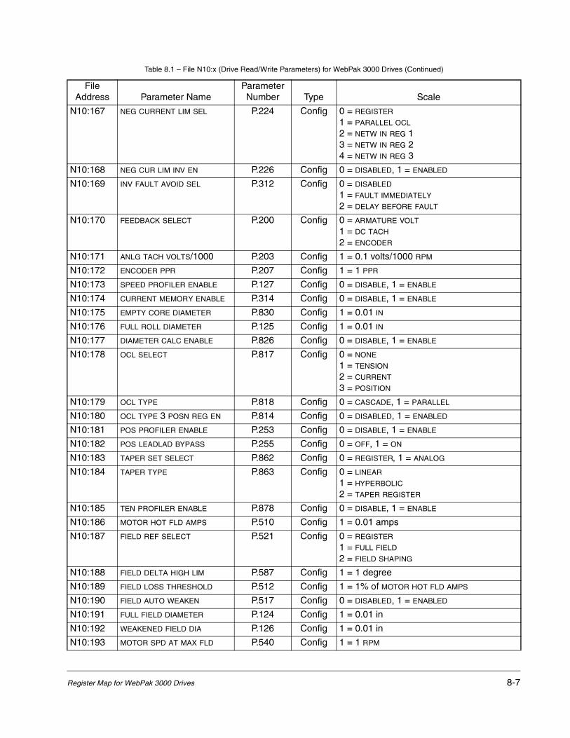
Register Map for WebPak 3000 Drives 8-7
N10:167 NEG CURRENT LIM SEL P.224 Config 0 = REGISTER
1 = PARALLEL OCL
2 = NETW IN REG 13 = NETW IN REG 24 = NETW IN REG 3
N10:168 NEG CUR LIM INV EN P.226 Config 0 = DISABLED, 1 = ENABLED
N10:169 INV FAULT AVOID SEL P.312 Config 0 = DISABLED
1 = FAULT IMMEDIATELY
2 = DELAY BEFORE FAULT
N10:170 FEEDBACK SELECT P.200 Config 0 = ARMATURE VOLT
1 = DC TACH
2 = ENCODER
N10:171 ANLG TACH VOLTS/1000 P.203 Config 1 = 0.1 volts/1000 RPM
N10:172 ENCODER PPR P.207 Config 1 = 1 PPR
N10:173 SPEED PROFILER ENABLE P.127 Config 0 = DISABLE, 1 = ENABLE
N10:174 CURRENT MEMORY ENABLE P.314 Config 0 = DISABLE, 1 = ENABLE
N10:175 EMPTY CORE DIAMETER P.830 Config 1 = 0.01 IN
N10:176 FULL ROLL DIAMETER P.125 Config 1 = 0.01 IN
N10:177 DIAMETER CALC ENABLE P.826 Config 0 = DISABLE, 1 = ENABLE
N10:178 OCL SELECT P.817 Config 0 = NONE
1 = TENSION
2 = CURRENT
3 = POSITION
N10:179 OCL TYPE P.818 Config 0 = CASCADE, 1 = PARALLEL
N10:180 OCL TYPE 3 POSN REG EN P.814 Config 0 = DISABLED, 1 = ENABLED
N10:181 POS PROFILER ENABLE P.253 Config 0 = DISABLE, 1 = ENABLE
N10:182 POS LEADLAD BYPASS P.255 Config 0 = OFF, 1 = ON
N10:183 TAPER SET SELECT P.862 Config 0 = REGISTER, 1 = ANALOG
N10:184 TAPER TYPE P.863 Config 0 = LINEAR
1 = HYPERBOLIC
2 = TAPER REGISTER
N10:185 TEN PROFILER ENABLE P.878 Config 0 = DISABLE, 1 = ENABLE
N10:186 MOTOR HOT FLD AMPS P.510 Config 1 = 0.01 amps
N10:187 FIELD REF SELECT P.521 Config 0 = REGISTER
1 = FULL FIELD
2 = FIELD SHAPING
N10:188 FIELD DELTA HIGH LIM P.587 Config 1 = 1 degree
N10:189 FIELD LOSS THRESHOLD P.512 Config 1 = 1% of MOTOR HOT FLD AMPS
N10:190 FIELD AUTO WEAKEN P.517 Config 0 = DISABLED, 1 = ENABLED
N10:191 FULL FIELD DIAMETER P.124 Config 1 = 0.01 in
N10:192 WEAKENED FIELD DIA P.126 Config 1 = 0.01 in
N10:193 MOTOR SPD AT MAX FLD P.540 Config 1 = 1 RPM
Table 8.1 – File N10:x (Drive Read/Write Parameters) for WebPak 3000 Drives (Continued)
File Address Parameter Name
Parameter Number Type Scale

8-8 ControlNet Network Communication Option Board For Use With FlexPak 3000 and WebPak 3000 DC Drives
N10:194 FIELD CURRENT 1 P.522 Config 1 = 0.01 amp
N10:195 FIELD CURRENT 2 P.523 Config 1 = 0.01 amp
N10:196 FIELD CURRENT 3 P.524 Config 1 = 0.01 amp
N10:197 FIELD CURRENT 4 P.525 Config 1 = 0.01 amp
N10:198 FIELD CURRENT 5 P.526 Config 1 = 0.01 amp
N10:199 FIELD CURRENT 6 P.527 Config 1 = 0.01 amp
N10:200 FIELD CURRENT 7 P.528 Config 1 = 0.01 amp
N10:201 FIELD CURRENT 8 P.529 Config 1 = 0.01 amp
N10:202 FIELD INPUT 1 P.530 Config 1 = 1 RPM
N10:203 FIELD INPUT 2 P.531 Config 1 = 1 RPM
N10:204 FIELD INPUT 3 P.532 Config 1 = 1 RPM
N10:205 FIELD INPUT 4 P.533 Config 1 = 1 RPM
N10:206 FIELD INPUT 5 P.534 Config 1 = 1 RPM
N10:207 FIELD INPUT 6 P.535 Config 1 = 1 RPM
N10:208 FIELD INPUT 7 P.536 Config 1 = 1 RPM
N10:209 FIELD INPUT 8 P.537 Config 1 = 1 RPM
N10:210 FIELD SHAPING TYPE P.539 Config 0 = SPEED, 1 = DIAMETER
N10:211 CT TURNS RATIO P.010 Config
N10:212 JOG OFF DELAY TIME P.121 Config 1 = 1 s
N10:213 STOP DECEL SELECT P.122 Config 1 = 0.1 s
N10:214 NOMINAL AC LINE FREQ P.306 Config 1 = 1 Hz
N10:215 NOMINAL AC LINE VOLTS P.307 Config 1 = 1 VAC
N10:216 PHASE LOSS DETECT EN P.609 Config 0 = DISABLE, 1 = ENABLE
N10:217 DIG OUT 1 SELECT P.409 Config 0 = LEVEL DETECTOR OUT 11 = LEVEL DETECTOR OUT 22 = At speed3 = In current limit4 = Drive ready5 = CURRENT MEM COMMAND
6 = UNDERWIND COMMAND
7 = TENSION COMMAND
8 = STALL TENSION COMMAND
9 = SLACK TAKE UP COMMAND
10 = DIAMETER RESET TP
11 = ARMATURE BRIDGE POL
12 = FIELD ECONOMY ACTIVE
13 = NETW COMM STATUS
14 = NETW IN REG 115 = NETW IN REG 216 = NETW IN REG 317 = SPEED PROFILER ENABLE
18 = DIAMETER CALC ENABLE
Table 8.1 – File N10:x (Drive Read/Write Parameters) for WebPak 3000 Drives (Continued)
File Address Parameter Name
Parameter Number Type Scale

Register Map for WebPak 3000 Drives 8-9
N10:218 DIG OUT 1 CONTACT TYP P.410 Config 0 = NORMAL OPEN
1 = NORMAL CLOSED
N10:219 DIG OUT 2 SELECT P.411 Config 0 = LEVEL DETECTOR OUT 11 = LEVEL DETECTOR OUT 22 = At speed3 = In current limit4 = Drive ready5 = CURRENT MEM COMMAND
6 = UNDERWIND COMMAND
7 = TENSION COMMAND
8 = STALL TENSION COMMAND
9 = SLACK TAKE UP COMMAND
10 = DIAMETER RESET TP
11 = ARMATURE BRIDGE POL
12 = FIELD ECONOMY ACTIVE
13 = NETW COMM STATUS
14 = NETW IN REG 115 = NETW IN REG 216 = NETW IN REG 317 = SPEED PROFILER ENABLE
18 = DIAMETER CALC ENABLE
N10:220 DIG OUT 2 CONTACT TYP P.412 Config 0 = NORMAL OPEN
1 = NORMAL CLOSED
N10:221 LINE SPEED SIG TYPE P.100 Config 0 = 0 to 10 V1 = +/-10 V2 = 4 to 20 mA3 = 10 to 50 mA
N10:222 TENSION SETPT SIG TYP P.413 Config 0 = 0 to 10 V1 = +/-10 V2 = 4 to 20 mA3 = 10 to 50 mA
N10:223 ANLG OUT 3 SIG TYPE P.419 Config 0 = 0 to 10 V1 = +/-10 V2 = 4 to 20 mA3 = 10 to 50 mA
Table 8.1 – File N10:x (Drive Read/Write Parameters) for WebPak 3000 Drives (Continued)
File Address Parameter Name
Parameter Number Type Scale

8-10 ControlNet Network Communication Option Board For Use With FlexPak 3000 and WebPak 3000 DC Drives
N10:224 ANLG OUT 3 SELECT P.418 Config 0 = CML FEEDBACK
1 = CML REFERENCE
2 = CML ERROR
3 = SPD LOOP FEEDBACK
4 = SPD LOOP REFERENCE
5 = SPD LOOP ERROR
6 = SPD LOOP OUTPUT
7 = SPEED RAMP OUTPUT
8 = SPD RAMP INPUT TP
9 = ARMATURE VOLTAGE
10 = ANALOG TACH FEEDBACK
11 = ENCODER FEEDBACK
12 = SPD SOURCE SELECT OUT
13 = TRIM OUTPUT
14 = FIELD REFERENCE
15 = FIELD FEEDBACK
16 = TEN RAMP OUTPUT
17 = POS RAMP OUTPUT
18 = OCL PARALLEL OUT
19 = OCL OUTPUT
20 = Power out21 = NETW IN REG 122 = NETW IN REG 223 = NETW IN REG 324 = Zero25 = Full scale26 = DANCER LOADING
27 = TENSION DEMAND
28 = TAPER PERCENT
29 = DIAMETER ANALOG
30 = INERTIA COMPENSATION
Table 8.1 – File N10:x (Drive Read/Write Parameters) for WebPak 3000 Drives (Continued)
File Address Parameter Name
Parameter Number Type Scale

Register Map for WebPak 3000 Drives 8-11
N10:225 ANLG OUT 4 SELECT P.421 Config 0 = CML FEEDBACK
1 = CML REFERENCE
2 = CML ERROR
3 = SPD LOOP FEEDBACK
4 = SPD LOOP REFERENCE
5 = SPD LOOP ERROR
6 = SPD LOOP OUTPUT
7 = SPEED RAMP OUTPUT
8 = SPD RAMP INPUT TP
9 = ARMATURE VOLTAGE
10 = ANALOG TACH FEEDBACK
11 = ENCODER FEEDBACK
12 = SPD SOURCE SELECT OUT
13 = TRIM OUTPUT
14 = FIELD REFERENCE
15 = FIELD FEEDBACK
16 = TEN RAMP OUTPUT
17 = POS RAMP OUTPUT
18 = OCL PARALLEL OUT
19 = OCL OUTPUT
20 = Power out21 = NETW IN REG 122 = NETW IN REG 223 = NETW IN REG 324 = Zero25 = Full scale26 = DANCER LOADING
27 = TENSION DEMAND
28 = TAPER PERCENT
29 = DIAMETER ANALOG
30 = INERTIA COMPENSATION
N10:226 FREQ IN ZERO P.423 Config 1 = 0.1 kHz
N10:227 FREQ IN FULL SCALE P.424 Config 1 = 0.1 kHz
Table 8.1 – File N10:x (Drive Read/Write Parameters) for WebPak 3000 Drives (Continued)
File Address Parameter Name
Parameter Number Type Scale

8-12 ControlNet Network Communication Option Board For Use With FlexPak 3000 and WebPak 3000 DC Drives
N10:228 FREQ OUT SELECT P.425 Config 0 = CML FEEDBACK
1 = CML REFERENCE
2 = CML ERROR
3 = SPD LOOP FEEDBACK
4 = SPD LOOP REFERENCE
5 = SPD LOOP ERROR
6 = SPD LOOP OUTPUT
7 = SPEED RAMP OUTPUT
8 = SPD RAMP INPUT TP
9 = ARMATURE VOLTAGE
10 = ANALOG TACH FEEDBACK
11 = ENCODER FEEDBACK
12 = SPD SOURCE SELECT OUT
13 = TRIM OUTPUT
14 = FIELD REFERENCE
15 = FIELD FEEDBACK
16 = TEN RAMP OUTPUT
17 = POS RAMP OUTPUT
18 = OCL PARALLEL OUT
19 = OCL OUTPUT
20 = Power out21 = NETW IN REG 122 = NETW IN REG 223 = NETW IN REG 324 = Zero25 = Full scale26 = DANCER LOADING
27 = TENSION DEMAND
28 = TAPER PERCENT
29 = DIAMETER ANALOG
30 = INERTIA COMPENSATION
N10:229 FREQ OUT ZERO P.426 Config 1 = 0.1 kHz
N10:230 FREQ OUT FULL SCALE P.427 Config 1 = 0.1 kHz
Table 8.1 – File N10:x (Drive Read/Write Parameters) for WebPak 3000 Drives (Continued)
File Address Parameter Name
Parameter Number Type Scale

Register Map for WebPak 3000 Drives 8-13
N10:231 LEVEL DETECT 1A SEL P.602 Config 0 = LEVEL REGISTER 11 = LEVEL REGISTER 22 = CML SPEED REFERENCE
3 = CML REFERENCE
4 = CML FEEDBACK
5 = CML ERROR
6 = SPD SOURCE SELECT OUT
7 = SPEED RAMP OUTPUT
8 = SPD LOOP REFERENCE
9 = SPD LOOP FEEDBACK
10 = SPD LOOP OUTPUT
11 = TRIM OUTPUT
12 = NORM FIELD REF
13 = FIELD DELTA
14 = FIELD FEEDBACK
15 = FIELD REFERENCE
16 = TEN LOOP ERROR
17 = TENSION DEMAND
18 = TEN/DANCER FDBK SCALED
19 = POS LOOP ERROR
20 = DANCER LOADING
21 = OCL OUTPUT
22 = OCL PARALLEL OUT
23 = NORM ROLL DIAMETER
24 = LOSSES COMPENSATION
25 = INERTIA COMPENSATION
26 = INSTANTANEOUS INERTIA
27 = TAPER PERCENT
28 = CURRENT MEM COMMAND
29 = STALL TENSION COMMAND
30 = NETW IN REG 131 = NETW IN REG 2
Table 8.1 – File N10:x (Drive Read/Write Parameters) for WebPak 3000 Drives (Continued)
File Address Parameter Name
Parameter Number Type Scale

8-14 ControlNet Network Communication Option Board For Use With FlexPak 3000 and WebPak 3000 DC Drives
N10:232 LEVEL DETECT 1B SEL P.610 Config 0 = LEVEL REGISTER 11 = LEVEL REGISTER 22 = CML SPEED REFERENCE
3 = CML REFERENCE
4 = CML FEEDBACK
5 = CML ERROR
6 = SPD SOURCE SELECT OUT
7 = SPEED RAMP OUTPUT
8 = SPD LOOP REFERENCE
9 = SPD LOOP FEEDBACK
10 = SPD LOOP OUTPUT
11 = TRIM OUTPUT
12 = NORM FIELD REF
13 = FIELD DELTA
14 = FIELD FEEDBACK
15 = FIELD REFERENCE
16 = TEN LOOP ERROR
17 = TENSION DEMAND
18 = TEN/DANCER FDBK SCALED
19 = POS LOOP ERROR
20 = DANCER LOADING
21 = OCL OUTPUT
22 = OCL PARALLEL OUT
23 = NORM ROLL DIAMETER
24 = LOSSES COMPENSATION
25 = INERTIA COMPENSATION
26 = INSTANTANEOUS INERTIA
27 = TAPER PERCENT
28 = CURRENT MEM COMMAND
29 = STALL TENSION COMMAND
30 = NETW IN REG 131 = NETW IN REG 2
Table 8.1 – File N10:x (Drive Read/Write Parameters) for WebPak 3000 Drives (Continued)
File Address Parameter Name
Parameter Number Type Scale
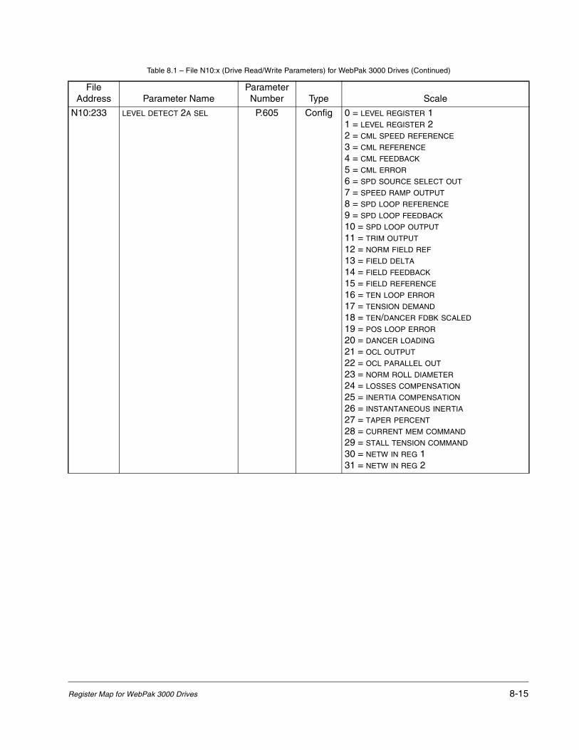
Register Map for WebPak 3000 Drives 8-15
N10:233 LEVEL DETECT 2A SEL P.605 Config 0 = LEVEL REGISTER 11 = LEVEL REGISTER 22 = CML SPEED REFERENCE
3 = CML REFERENCE
4 = CML FEEDBACK
5 = CML ERROR
6 = SPD SOURCE SELECT OUT
7 = SPEED RAMP OUTPUT
8 = SPD LOOP REFERENCE
9 = SPD LOOP FEEDBACK
10 = SPD LOOP OUTPUT
11 = TRIM OUTPUT
12 = NORM FIELD REF
13 = FIELD DELTA
14 = FIELD FEEDBACK
15 = FIELD REFERENCE
16 = TEN LOOP ERROR
17 = TENSION DEMAND
18 = TEN/DANCER FDBK SCALED
19 = POS LOOP ERROR
20 = DANCER LOADING
21 = OCL OUTPUT
22 = OCL PARALLEL OUT
23 = NORM ROLL DIAMETER
24 = LOSSES COMPENSATION
25 = INERTIA COMPENSATION
26 = INSTANTANEOUS INERTIA
27 = TAPER PERCENT
28 = CURRENT MEM COMMAND
29 = STALL TENSION COMMAND
30 = NETW IN REG 131 = NETW IN REG 2
Table 8.1 – File N10:x (Drive Read/Write Parameters) for WebPak 3000 Drives (Continued)
File Address Parameter Name
Parameter Number Type Scale
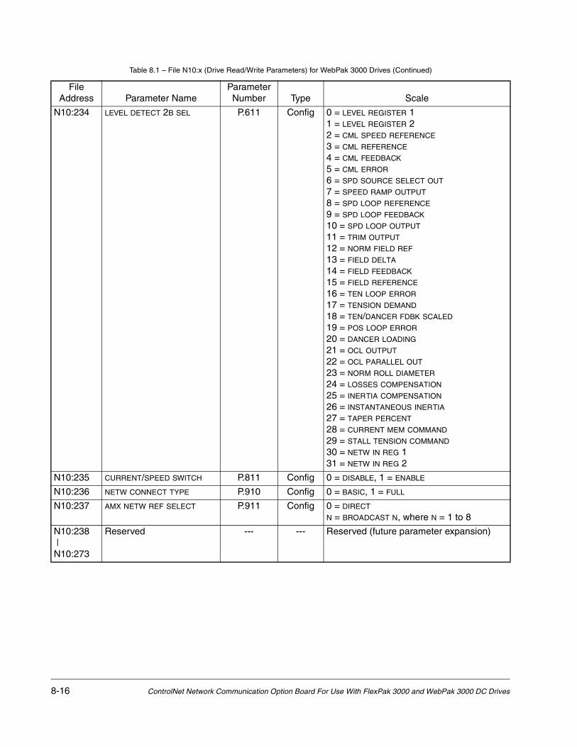
8-16 ControlNet Network Communication Option Board For Use With FlexPak 3000 and WebPak 3000 DC Drives
N10:234 LEVEL DETECT 2B SEL P.611 Config 0 = LEVEL REGISTER 11 = LEVEL REGISTER 22 = CML SPEED REFERENCE
3 = CML REFERENCE
4 = CML FEEDBACK
5 = CML ERROR
6 = SPD SOURCE SELECT OUT
7 = SPEED RAMP OUTPUT
8 = SPD LOOP REFERENCE
9 = SPD LOOP FEEDBACK
10 = SPD LOOP OUTPUT
11 = TRIM OUTPUT
12 = NORM FIELD REF
13 = FIELD DELTA
14 = FIELD FEEDBACK
15 = FIELD REFERENCE
16 = TEN LOOP ERROR
17 = TENSION DEMAND
18 = TEN/DANCER FDBK SCALED
19 = POS LOOP ERROR
20 = DANCER LOADING
21 = OCL OUTPUT
22 = OCL PARALLEL OUT
23 = NORM ROLL DIAMETER
24 = LOSSES COMPENSATION
25 = INERTIA COMPENSATION
26 = INSTANTANEOUS INERTIA
27 = TAPER PERCENT
28 = CURRENT MEM COMMAND
29 = STALL TENSION COMMAND
30 = NETW IN REG 131 = NETW IN REG 2
N10:235 CURRENT/SPEED SWITCH P.811 Config 0 = DISABLE, 1 = ENABLE
N10:236 NETW CONNECT TYPE P.910 Config 0 = BASIC, 1 = FULL
N10:237 AMX NETW REF SELECT P.911 Config 0 = DIRECT
N = BROADCAST N, where N = 1 to 8
N10:238 |N10:273
Reserved --- --- Reserved (future parameter expansion)
Table 8.1 – File N10:x (Drive Read/Write Parameters) for WebPak 3000 Drives (Continued)
File Address Parameter Name
Parameter Number Type Scale

Register Map for WebPak 3000 Drives 8-17
Table 8.2 – File N11:x (Drive Display Data (Read Only)) for WebPak 3000 Drives
File Address Parameter Name
Parameter Number Description
N11:0 Drive Status Word 1 --- b00 Readyb01 Runningb02 Fault Activeb03 Jogging Fwdb04 Jogging Revb05 Underwind Activeb06 Stoppingb07 Tension on Activeb08 Stall Tension Activeb09 Current Memory Activeb10 Current Limitb11 Alarm Activeb12 Current/Speed Activeb13 Processing Errorb14 Level Detect 1 Outputb15 Level Detect 2 Output
N11:1 Drive Status Word 2 --- b00 FN/DB Status (0 = open, 1 = closed)b01 TB Customer Interlock (0 = open, 1 = closed)b02 TB Section Runb03 TB Jog Revb04 TB Jog Fwdb05 TB Section Offb06 TB Coast/DB Interlock b07 TB Fault Resetb08 TB Diameter Sel Ab09 TB Diameter Sel Bb10 TB Diameter Resetb11 TB Tension Onb12 TB Current Memoryb13 TB Underwindb14 TB Slack Take Upb15 Reserved
N11:2 SPD LOOP REFERENCE P.295 Final speed loop reference value before the speed regulator
N11:3 SPD LOOP FEEDBACK P.296 Speed loop feedback value, after all conditioning and scaling
N11:4 SPD LOOP OUTPUT P.299 Speed loop PI output value
N11:5 ARMATURE VOLTAGE P.289 Armature voltage value after scaling, before IR compensation
N11:6 Average CML Feedback --- Current Minor Loop feedback average over last 8 CML scans
N11:7 Network Output Reg 1 --- Value of parameter from NETW OUT REG 1 SELECT (P.902)
N11:8 Network Output Reg 2 --- Value of parameter from NETW OUT REG 2 SELECT (P.903)

8-18 ControlNet Network Communication Option Board For Use With FlexPak 3000 and WebPak 3000 DC Drives
N11:9 Network Output Reg 3 --- Value of parameter from NETW OUT REG 3 SELECT (P.904)
N11:10 NETW IN REG 1 P.905 Present value of Network Input Register 1
N11:11 NETW IN REG 2 P.906 Present value of Network Input Register 2
N11:12 NETW IN REG 3 P.907 Present value of Network Input Register 3
N11:13 Drive Fault Word 1(latched)
--- b00 Line Synchronization Loss b01 Field Current Loss b02 Sustained Overload b03 Self Tune b04 Motor Thermostat b05 Controller Thermostat b06 Blower Motor Starter Open b07 Shorted SCR b08 Instantaneous Overcurrentb09 Overspeed/Overvoltageb10 Open SCRb11 Open Armatureb12 Tachometer Lossb13 OIM Communicationb14 Network Communicationb15 Tracking (reversed tach) Error
N11:14 Drive Fault Word 2(latched)
--- Reserved
N11:15 Drive Alarm Word(latched)
--- b00 Reservedb01 AC line voltage low (<90%)b02 AC line voltage high (>115%) b03 Reserved |b15 Reserved
N11:16 Drive Stop Cause Word --- b00 Stop asserted b01 Jog de-asserted for > 1 second b02 Internal stop request b03 Current Limit stop b04 Ramp stop b05 Coast/DB stop b06 Fault stop (or self tune completed) b07 Customer Interlock opened b08 Coast/DB Interlock openedb09 Main contactor openedb10 Reserved |b15 Reserved
N11:17 LINE SPEED P.188 Analog reference value output by the drive after scaling
N11:18 TORQUE REFERENCE P.189 Present torque (current) reference value
N11:19 SPD SOURCE SELECT OUT P.193 Selected speed source value
Table 8.2 – File N11:x (Drive Display Data (Read Only)) for WebPak 3000 Drives (Continued)
File Address Parameter Name
Parameter Number Description

Register Map for WebPak 3000 Drives 8-19
N11:20 SPEED CROSS OVER P.133 Speed loop cross over frequency
N11:21 SPEED PI WLD OUT P.250 Value of the speed loop PI low frequency
N11:22 SPEED PI KP OUT P.251 Value of the speed loop PI proprotional gain
N11:23 SPEED LAG FREQ OUT P.252 Value of the speed loop lag frequency
N11:24 DRAW PERCENTAGE OUT P.196 Product of selected trim reference and TRIM RANGE (P.109)
N11:25 TRIM OUTPUT P.197 Present value added to SPD SOURCE SELECT OUt (P.193)
N11:26 SPEED RAMP INPUT TP P.198 Speed reference value immediately before S-CURVE ramp.
N11:27 SPEED RAMP OUTPUT P.199 Speed reference value immediately after S-curve ramp
N11:28 INSTANTANEOUS INERTIA P.230 Calculated value of the dynamic load inertia as provided by the inertia compensation task
N11:29 INERTIA COMPENSATION P.244 Output of the inertia compensation calculator
N11:30 LOSSES COMPENSATION P.316 Output of the losses compensation calculator
N11:31 IR COMPENSATION TP P.290 Value subtracted from ARMATURE VOLTAGE (P.289)
N11:32 ANALOG TACH FEEDBACK P.291 Analog tachometer value after scaling
N11:33 ENCODER FEEDBACK P.292 Encoder value after scaling
N11:34 CURRENT COMPOUND TP P.293 Value subtracted from SPEED RAMP OUTPUT (P.199)
N11:35 JOG RAMP OUTPUT P.294 Jog reference value immediately after jog ramp
N11:36 SPD LOOP ERROR P.297 Difference between SPD LOOP REFERENCE (P.295) and SPD LOOP FEEDBACK (P.296)
N11:37 SPD LOOP LAG OUTPUT P.298 Value immediately after speed loop forward path lag
N11:38 CML RAMP INPUT TP P.390 Current reference value to the CML ramp block
N11:39 CML SPEED REFERENCE P.391 Speed reference value to the current minor loop
N11:40 AC LINE VOLTAGE P.392 Measured AC line voltage (RMS value)
N11:41 AC LINE PERIOD P.393 Measured AC line period (µsec)
N11:42 ARMATURE BRIDGE POL P.394 0 = OFF (forward bridge active)1 = ON (reverse bridge active)
N11:43 J18 ARM I FB RESISTOR P.395 1 = 15 ohm, 2 = 20 ohm, 3 = 30 ohm, 4 = 39 ohm
N11:44 CML REFERENCE P.396 Reference value to the CML after rate and amplitude limiting
N11:45 CML FEEDBACK (10 ms update)
P.397 CML feedback value after conditioning and scaling
N11:46 CML ERROR P.398 Difference between CML REFERENCE (P.396) and CML FEEDBACK (P.297)
N11:47 ARMATURE DELTA P.399 Present armature firing angle in µsec
N11:48 UNDERWIND DIN TP P.490 0 = OFF, 1 = ON
N11:49 UNDERWIND COMMAND P.877 0 = OFF, 1 = ON
N11:50 FREQ IN P.491 Frequency input (terminals 39, 40, 41 on the I/O Expansion board)
Table 8.2 – File N11:x (Drive Display Data (Read Only)) for WebPak 3000 Drives (Continued)
File Address Parameter Name
Parameter Number Description

8-20 ControlNet Network Communication Option Board For Use With FlexPak 3000 and WebPak 3000 DC Drives
N11:51 TENSION SETPOINT IN P.492 Digital value of the tension setpoint input after gain and zero have been applied
N11:52 TENSION/DANCER FDBK P.493 Digital value of the tension/dancer feedback input after gain and zero have been applied
N11:53 DANCER LOADING P.820 Rate-limited and scaled value of TENSION DEMAND (P.844)
N11:54 SLACK TAKE UP DIN TP P.494 0 = OFF, 1 = ON
N11:55 SLACK TAKE UP COMMAND P.317 0 = OFF, 1 = ON
N11:56 CURRENT MEM DIN TP P.499 0 = OFF, 1 = ON
N11:57 CURRENT MEM COMMAND P.319 0 = OFF, 1 = ON
N11:58 FLD CURRENT REGULATOR P.586 0 = NOT INSTALLED
1 = 4 amp2 = 10 amp3 = 20 amp
N11:59 FIELD DELTA P.588 Field firing angle in degrees
N11:60 FIELD FEEDBACK
(10 ms update)P.589 Motor field feedback value
N11:61 FIELD REFERENCE P.590 Field current reference value
N11:62 NORM FIELD REF P.130 Normalized reference to the field shaping table
N11:63 FIELD ECONOMY ACTIVE P.599 0 = OFF, 1 = ON
N11:64 LEVEL DETECT 1 OUTPUT P.648 0 = OFF, 1 = ON
N11:65 LEVEL DETECT 2 OUTPUT P.649 0 = OFF, 1 = ON
N11:66 J11 ANLG TACH VLT SCL P.792 0 = 161 = 31/1252 = 62/250
N11:67 J14 ANLG TACH VLT RNG P.793 0 = LOW, 1 = HIGH
N11:68 REGULATOR SW VERSION P.794 V.VV, Regulator board firmware version number
N11:69 POWER UNIT TYPE P.795 0 = S6R, 1 = S6
N11:70 NETWORK KIT P.796 0 = NOT INSTALLED
1 = INSTALLED
2 = FAILED DIAGS
N11:71 I/O EXPANSION KIT P.797 0 = NOT INSTALLED
1 = INSTALLED
2 = FAILED DIAGS
N11:72 ENCODER KIT P.798 0 = NOT INSTALLED
1 = INSTALLED
2 = FAILED DIAGS
N11:73 J15 REGULATOR TYPE P.799 0 = SPEED/VOLTAGE, 1 = CURRENT/TORQUE
N11:74 OCL PARALLEL OUT P.816 Output of the selected outer control loop for parallel mode
N11:75 OCL OUTPUT P.848 OCL output value added to SPEED RAMP OUTPUT (P.199)
N11:76 POS RAMP OUTPUT P.237 Output of the position major loop ramp block
Table 8.2 – File N11:x (Drive Display Data (Read Only)) for WebPak 3000 Drives (Continued)
File Address Parameter Name
Parameter Number Description

Register Map for WebPak 3000 Drives 8-21
N11:77 POSITION VERNIER P.241 Output of the position major loop
N11:78 POS LL WLO OUT P.246 Value of the position loop lead/lag low frequency
N11:79 POS LL RATIO OUT P.247 Value of the position loop lead/lag ratio
N11:80 POS PI KP OUT P.248 Value of the position loop PI proportional gain
N11:81 POS PI WLD OUT P.249 Value of the position loop PI lead frequency
N11:82 POS LOOP ERROR P.254 The difference between POSITION REFERENCE (P.240) and position feedback
N11:83 TEN/DANCER FDBK SCALED P.489 Output of the tension/dancer feedback scaling block
N11:84 TENSION ON DIN TP P.498 0 = OFF, 1 = ON
N11:85 TENSION COMMAND P.850 0 = OFF, 1 = ON
N11:86 STALL TENSION COMMAND P.899 0 = OFF, 1 = ON
N11:87 TEN TO CURRENT OUT P.876 Output of the tension loop’s tension-to-current scaling block
N11:88 TEN PI KP OUT P.879 Value of the tension loop PI proportional gain
N11:89 TENSION VERNIER P.856 Output of the tension major loop in counts
N11:90 TAPER PERCENT P.859 Percent reduction to be applied to the tension reference from the taper function
N11:91 TEN LOOP ERROR P.834 Difference between the tension ramp output and the tension/current loop feedback signal
N11:92 TEN RAMP OUTPUT P.842 Output of the tension major loop ramp block after tension-to-current conversion
N11:93 TENSION DEMAND P.844 Output of the tension setpoint generator in counts
N11:94 ROLL DIAMETER P.865 Value of the calculated roll diameter in engineering units
N11:95 NORM ROLL DIAMETER P.131 Value of the roll diameter normalized at 1.000 at EMPTY CORE DIAMETER (P.830)
N11:96 DIAMETER CALC OUTPUT P.132 Value of the calculated roll diameter normalized at 1.000 at EMPTY CORE DIAMETER (P.830)
N11:97 DIAMETER ANALOG P.821 Output of the diameter calculator scaled from zero at empty core to 4095 at full roll diameter
N11:98 DIAMETER/TAPER IN TP P.192 Value of the diameter/taper range input in counts after gain and zero have been applied
N11:99 UNWIND DIAMETER IN P.828 Analog signal of diameter/taper analog input when DIAMETER/TAPER SELECT (P.870) is set to diameter.
N11:100 DIAMETER SELECT A TP P.495 0 = OFF, 1 = ON
N11:101 DIAMETER SELECT B TP P.496 0 = OFF, 1 = ON
N11:102 DIAMETER RESET TP P.829 0 = OFF, 1 = ON
N11:103 DIAMETER RST DIN TP P.497 0 = OFF, 1 = ON
N11:104 NETW COMM STATUS P.908 0 = NOT ACTIVE, 1 = ACTIVE
Table 8.2 – File N11:x (Drive Display Data (Read Only)) for WebPak 3000 Drives (Continued)
File Address Parameter Name
Parameter Number Description
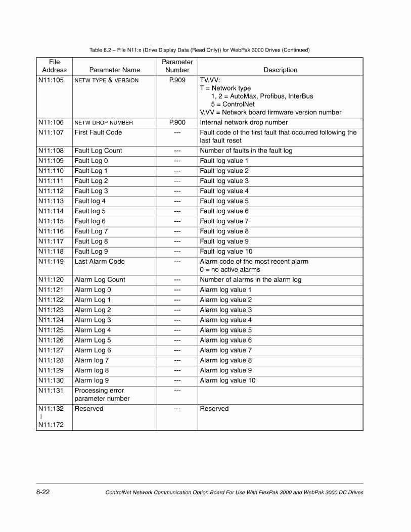
8-22 ControlNet Network Communication Option Board For Use With FlexPak 3000 and WebPak 3000 DC Drives
N11:105 NETW TYPE & VERSION P.909 TV.VV:T = Network type 1, 2 = AutoMax, Profibus, InterBus 5 = ControlNetV.VV = Network board firmware version number
N11:106 NETW DROP NUMBER P.900 Internal network drop number
N11:107 First Fault Code --- Fault code of the first fault that occurred following the last fault reset
N11:108 Fault Log Count --- Number of faults in the fault log
N11:109 Fault Log 0 --- Fault log value 1
N11:110 Fault Log 1 --- Fault log value 2
N11:111 Fault Log 2 --- Fault log value 3
N11:112 Fault Log 3 --- Fault log value 4
N11:113 Fault log 4 --- Fault log value 5
N11:114 Fault log 5 --- Fault log value 6
N11:115 Fault log 6 --- Fault log value 7
N11:116 Fault Log 7 --- Fault log value 8
N11:117 Fault Log 8 --- Fault log value 9
N11:118 Fault Log 9 --- Fault log value 10
N11:119 Last Alarm Code --- Alarm code of the most recent alarm 0 = no active alarms
N11:120 Alarm Log Count --- Number of alarms in the alarm log
N11:121 Alarm Log 0 --- Alarm log value 1
N11:122 Alarm Log 1 --- Alarm log value 2
N11:123 Alarm Log 2 --- Alarm log value 3
N11:124 Alarm Log 3 --- Alarm log value 4
N11:125 Alarm Log 4 --- Alarm log value 5
N11:126 Alarm Log 5 --- Alarm log value 6
N11:127 Alarm Log 6 --- Alarm log value 7
N11:128 Alarm log 7 --- Alarm log value 8
N11:129 Alarm log 8 --- Alarm log value 9
N11:130 Alarm log 9 --- Alarm log value 10
N11:131 Processing error parameter number
---
N11:132 |N11:172
Reserved --- Reserved
Table 8.2 – File N11:x (Drive Display Data (Read Only)) for WebPak 3000 Drives (Continued)
File Address Parameter Name
Parameter Number Description

Register Map for WebPak 3000 Drives 8-23
Table 8.3 – File N12:x (Drive Reference and Feedback Data) for WebPak 3000 Drives
Drive Reference Data Drive Feedback Data (Read Only)
N12:0 Drive Control Word (Read Only) N12:16 Drive Status Word 1
N12:1 Reserved N12:17 Reserved
N12:2 Network Input Reg #1 (R/W) N12:18 Speed Feedback
N12:3 Network Input Reg #2 (R/W) N12:20 Current Feedback
N12:4 Network Input Reg #3 (R/W) N12:21 Network Output Reg #1
N12:5 Field Reference (R/W) N12:22 Network Output Reg #2
N12:6 Reserved |N12:15
N12:23 Network Output Reg #3
N12:24 Reserved |N12:31

8-24 ControlNet Network Communication Option Board For Use With FlexPak 3000 and WebPak 3000 DC Drives

Communication Error Codes 9-1
CHAPTER 9Communication Error Codes
Table 9.1 defines the error codes that are returned by the drive for Typed Read and Typed Write messages.
Table 9.1 – Error Codes
Status
Description
ControlLogix™ PLC-5
Error Extended Error Error
0 0 0 No Error
00F0 0002 -4094 (0xF002) Incomplete address
00F0 0003 -4093 (0xF003) Incorrect address
00F0 0006 -4090 (0xF006) Addressed file does not exist in target processor
00F0 0007 -4089 (0xF007) Destination file is too small for number of words requested
00F0 000B -4085 (0xF00B) Privilege error, access denied
00F0 000C -4084 (0xF00C) Requested function is not available
00F0 0011 -4079 (0xF011) Data type requested does not match available

9-2 ControlNet Network Communication Option Board For Use With FlexPak 3000 and WebPak 3000 DC Drives

Glossary-1
GLOSSARY
configuration manager node - The node responsible for distributing ControlNet configuration data to all nodes on the network.
configurable (parameter) - A parameter that can be adjusted or changed only when the drive is stopped.
ControlNet network - A communication architecture that allows the exchange of messages between Rockwell Automation products and certified third-party products.
connection - An opened communication path between two nodes on a ControlNet network.
ControlNet Status Indicators - Channel A and channel B indicators on your node indicating status on the ControlNet link.
drop cable - A cable that connects a node to the trunk cable.
frame - A single data transfer on a ControlNet link.
link - A collection of nodes within unique addresses (in range of 1-99). Segments connected by repeaters make up a link; links connected by bridges make up a network.
maximum scheduled node - The node with highest network address that can use scheduled time on a ControlNet link.
maximum unscheduled node -The node with highest network address that can use unscheduled time on a ControlNet link.
MSG instruction (message instruction) - Instructions used by ControlNet PLC-5 processors for peer-to-peer communications.
NAP (Network Access Port) - A port that provides a temporary network connection through an RJ-45 connector.
network - A series of nodes connected by some type of communication medium. The connection paths between any pair of nodes can include repeaters, routers, bridges, and gateways.
network address - A node's address on the network.
node - The port of a physical device connected to the network that requires a network address to function on the network. A link may contain a maximum of 107 nodes.
NUI (Network Update Interval) - A single occurrence of the network update time (NUT)

Glossary-2 ControlNet Network Communication Option Board For Use With FlexPak 3000 and WebPak 3000 DC Drives
NUT (Network Update Time) - Repetitive time interval in which data can be sent on the ControlNet network.
redundant media - A dual cable system that lets you receive the best signal over a network.
repeater - A two-port active physical-layer device that reconstructs and retransmits all traffic it hears on one segment to another segment.
sheduled transfer - Deterministic and repeatable transfers that are continuous and asynchronous to the ladder-logic program scan.
segment - Trunk-cable sections connected via taps with terminators at each end; a segment does not include repeaters.
tap - A component that connects products to the ControlNet trunk cable. A tap is required for each node and for both sides of each repeater.
terminator - A 75-Ω resistor (mounted in a BNC plug) placed on the ends of segments to prevent reflections from occurring at the ends of cables.
trunk-cable - The bus or central part of the ControlNet cable system.
trunk-cable section - The length of trunk cables between any two laps.
tunable (parameter) - A parameter that can be adjusted or changed when the drive is running or stopped.
unscheduled transfers - Non-deterministic data transfers through ladder-initiated communication or programming devices.

Index Index-1
INDEX
B
BNC connectors, 1-1, 1-2board installation, 2-1
C
CNI PROG/RUN MODE (P.915), 3-2communication error codes, 9-1communication loss response
FlexPak 3000 drives, 3-3WebPak 3000 drives, 3-2
connecting drive to ControlNet network, 2-3 to 2-4connectors
9-pin D-shell, 1-1BNC, 1-1locations of, 1-2ribbon cable, 1-1RJ-45, 1-1
contacting Reliance Electric, 1-3CONTROL SOURCE SELECT (P.000), 3-1ControlNet network communication, general
information about, 4-1ControlNet Network Option Board, description
of, 1-1ControlNet network, configuring drive for, 3-1 to 3-5
D
drive configuration, 3-1 to 3-5drive display data (N11:x), using, 4-10drive feedback data
FlexPak 3000 drives, 4-7general information, 4-6WebPak 3000 drives, 4-8
drive reference and feedback data (N12:x), using, 4-10
drive reference dataFlexPak 3000 drives, 4-4general information, 4-3WebPak 3000 drives, 4-5
drive, connecting to ControlNet network, 2-3 to 2-4D-shell connector, 1-1
E
error codes, 9-1
F
File N10:x (drive read/write parameters)FlexPak 3000 drives, 7-1 to 7-10WebPak 3000 drives, 8-1 to 8-16
File N11:x (drive display data (read-only))FlexPak 3000 drives, 7-11 to 7-15WebPak 3000 drives, 8-17 to 8-22
File N12:x (drive reference and feedback data)FlexPak 3000 drives, 7-16WebPak 3000 drives, 8-23
file numbers, 4-9FlexPak 3000 drives
drive feedback data, 4-7drive reference datas, 4-4file N10:x (drive read/write parameters), 7-1 to
7-10file N11:x (drive display data (read-only)), 7-11
to 7-15file N12:x (drive reference and feedback
data), 7-16register map, 7-1 to 7-16
I
Installation, 2-1
M
messagesscheduled, 4-1, 4-2unscheduled, 4-1
MSG instructiontiming, 4-9
N
N10:x (drive read/write parameters)FlexPak 3000 drives, 7-1 to 7-10WebPak 3000 drives, 8-1 to 8-16
N11:x (drive display data (read-only))FlexPak 3000 drives, 7-11 to 7-15

Index-2 ControlNet Network Communication Option Board For Use With FlexPak 3000 and WebPak 3000 DC Drives
WebPak 3000 drives, 8-17 to 8-22N12:x (drive reference and feedback data)
FlexPak 3000 drives, 7-16WebPak 3000 drives, 8-23
NETW COMM LOSS SELECT (P.901), 3-2 to 3-3NETW COMM STATUS (P.908), 3-4NETW DROP NUMBER (P.900), 3-1NETW IN REG 1 (P.905), 3-5NETW IN REG 2 (P.906), 3-5NETW IN REG 3 (P.907), 3-5NETW OUT REG 1 SELECT (P.902), 3-3NETW OUT REG 2 SELECT (P.903), 3-4NETW OUT REG 3 SELECT (P.904), 3-4NETW TYPE & VERSION (P.909), 3-4network
transfer rates, 4-1network access port
connecting a programming device to, 2-4description of, 1-1location of, 1-2
NETWORK KIT (P.796), 3-5network option board installation, 2-1network transfer rates, 4-1network update time (NUT), 4-1
P
programming the drive, 4-1 to 4-11
R
register mapFlexPak 3000 drives, 7-1 to 7-16WebPak 3000 drives, 8-1 to 8-23
Reliance Electric, contacting, 1-3ribbon cable connector, 1-1, 1-2RJ-45 connector, 1-1, 1-2RS-232 connector, 1-1, 1-2
S
scheduled data transfers, 4-2 to 4-3scheduled drive feedback data
FlexPak 3000 drives, 4-7general information, 4-6WebPak 3000 drives, 4-8
scheduled drive reference dataFlexPak 3000 drives, 4-4general information, 4-3WebPak 3000 drives, 4-5
T
transfer rates, network, 4-1, troubleshooting using write status (file N20:x), 4-10
U
unscheduled data transfers, 4-8 to 4-11
W
WebPak 3000 drivesdrive feedback data, 4-8drive reference data, 4-5file N10:x (drive read/write parameters), 8-1 to
8-16file N11:x (drive display data (read-only)), 8-17
to 8-22file N12:x (drive reference and feedback
data), 8-23register map, 8-1 to 8-23


U.S. Drives Technical Support Tel: (1) 262.512.8176, Fax: (1) 262.512.2222, Email: [email protected], Online: www.ab.com/support/abdrives
Publication D2-3425-3 – February 2005 Copyright © 2005 Rockwell Automation, Inc. All Rights Reserved. Printed in USA.