Embed Size (px)
DESCRIPTION
dcs
Citation preview
1Level 1Fundamentals TrainingFundamentals Training
2
Topics: Slide No:• Process Control Terminology 3 - 10• Control Principles 11 - 18• Basic Control Loop 19 - 23• Advance Control Loop 24 - 31• Control Algorithm 32 - 46• Control System 47 - 54• Exercise 55 - 59
ContentsContents
3
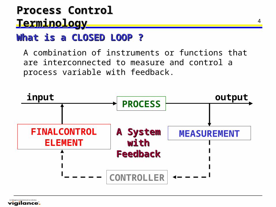
Any operation or sequence of operations involving a change in the substance being treated.Examples:
A change of energy state - hot to cold, liquid to gas
A change of composition - a chemical reactionA change of dimension - grinding coal
Process Control TerminologyProcess Control Terminology
What is a PROCESS ?What is a PROCESS ?
Types of PROCESS VARIABLE:Types of PROCESS VARIABLE:Pressure Specific Gravity of liquidFlow DensityLevel MassTemperature ConductivityLiquid Interface Composition
Moles
4
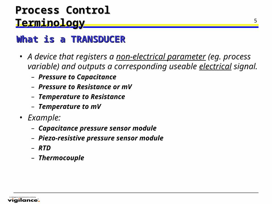
A combination of instruments or functions that are interconnected to measure and control a process variable with feedback.
Process Control TerminologyProcess Control Terminology
What is a CLOSED LOOP ?What is a CLOSED LOOP ?
PROCESSinput output
A System A System with with
FeedbackFeedback
FINALCONTROL ELEMENT
MEASUREMENT
CONTROLLER
5
• A device that registers a non-electrical parameter (eg. process variable) and outputs a corresponding useable electrical signal.– Pressure to Capacitance– Pressure to Resistance or mV– Temperature to Resistance– Temperature to mV
• Example:– Capacitance pressure sensor module– Piezo-resistive pressure sensor module– RTD– Thermocouple
Process Control TerminologyProcess Control Terminology
What is a TRANSDUCERWhat is a TRANSDUCER
6
• A device that will translate the transducers interpretation of the measured variable into a standard transmission signal.– 3 - 15 psi pneumatic signal– 4-20 mA dc electrical signal – 1-5 V dc electrical signal
Process Control TerminologyProcess Control Terminology
What is a TRANSMITTERWhat is a TRANSMITTER
7
• Lower installation cost– simple, twisted pair wiring
• Better noise immunity– current vs. voltage
• Insensitive to wire resistance– current vs. voltage
• Better suited for hazardous locations– intrinsic safety
Process Control TerminologyProcess Control Terminology
ADVANTAGE OF 4-20mA CURRENT SIGNALADVANTAGE OF 4-20mA CURRENT SIGNAL
8
• Used to keep a process variable at a desired value (set point).– Closed loop vs. Open loop control
• Difference: Open loop control has no feedback– Control Modes
• ON/OFF (Binary)• Proportional (P)• Proportional-plus-Integral (PI)• Proportional-plus-Integral-plus-Derivative (PID)
Process Control TerminologyProcess Control Terminology
What is a CONTROLLER ?What is a CONTROLLER ?
9Process Control TerminologyProcess Control Terminology
What is a SIGNAL ?What is a SIGNAL ?• An event that conveys data from one point to another.
What is an INDICATOR ?What is an INDICATOR ?• An instrument which visually shows the value of the variable.
Example : UM331,UM451,UM551,UM151
What is a RECORDER ?What is a RECORDER ?• An instrument that makes and displays a continuous graphic, acoustic or
magnetic record of a measured variable.
Example : Paperless Recorder DX Yokogawa , FX Yokogawa
What is a DCS ?What is a DCS ?• Distributed Control System consisting of functional integrated subsystems. The
subsystems are connected by a communication linkage (eg) data bus,data highway.
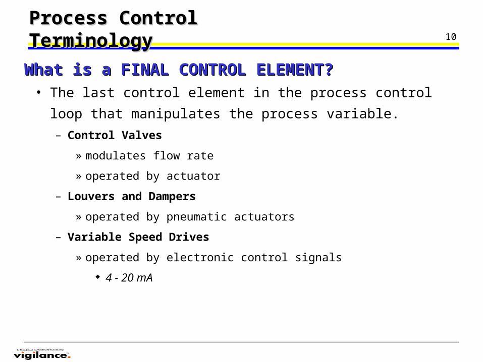
10Process Control TerminologyProcess Control Terminology
• The last control element in the process control loop that
manipulates the process variable.
– Control Valves
» modulates flow rate
» operated by actuator
– Louvers and Dampers
» operated by pneumatic actuators
– Variable Speed Drives
» operated by electronic control signals
4 - 20 mA
What is a FINAL CONTROL ELEMENT?What is a FINAL CONTROL ELEMENT?
11Control PrincipleControl Principle
12
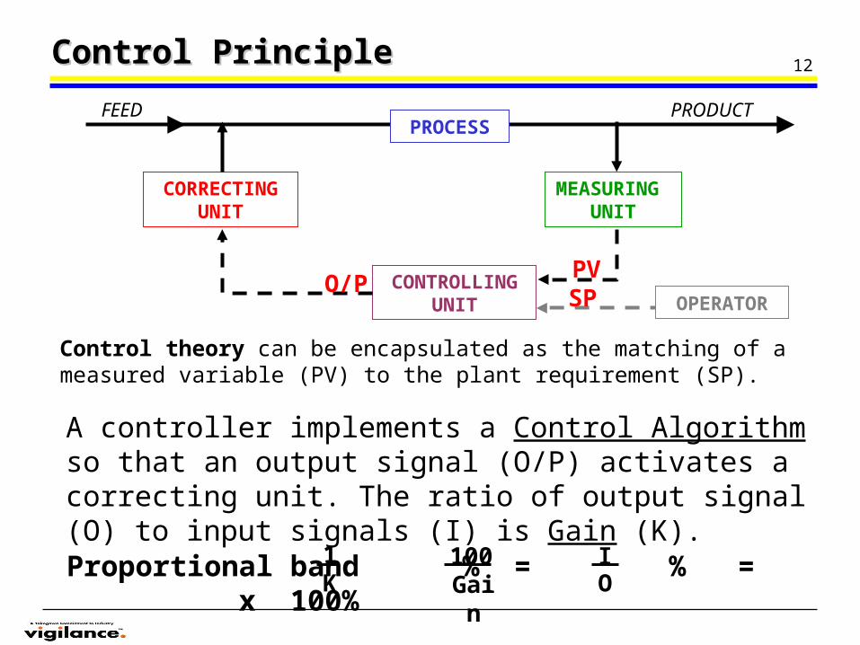
SPPV
Control PrincipleControl Principle
Control theory can be encapsulated as the matching of a measured variable (PV) to the plant requirement (SP).
PROCESS
CORRECTING UNIT
CONTROLLING UNIT
MEASURING UNIT
OPERATOR
FEED PRODUCT
Proportional band % = % = x 100%1K Gain
100 IO
O/P
A controller implements a Control Algorithm so that an output signal (O/P) activates a correcting unit. The ratio of output signal (O) to input signals (I) is Gain (K).
13Control PrincipleControl Principle
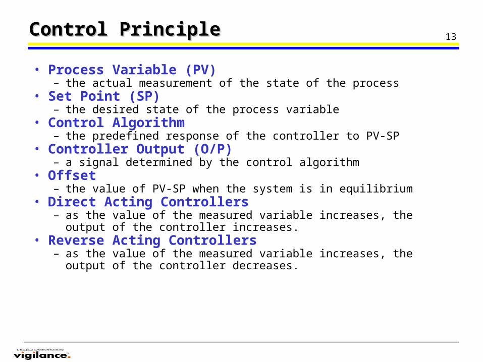
• Process Variable (PV)– the actual measurement of the state of the process
• Set Point (SP)– the desired state of the process variable
• Control Algorithm– the predefined response of the controller to PV-SP
• Controller Output (O/P)– a signal determined by the control algorithm
• Offset– the value of PV-SP when the system is in equilibrium
• Direct Acting Controllers– as the value of the measured variable increases, the output of the
controller increases.• Reverse Acting Controllers
– as the value of the measured variable increases, the output of the controller decreases.
14
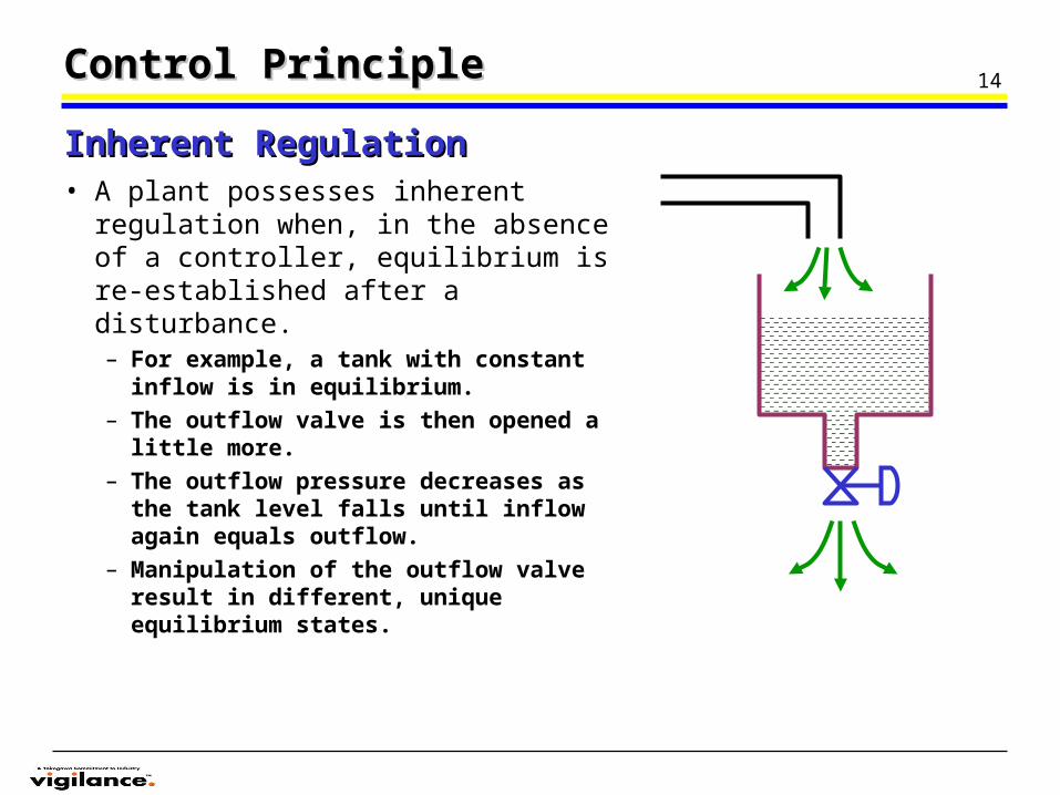
• A plant possesses inherent regulation when, in the absence of a controller, equilibrium is re-established after a disturbance.– For example, a tank with constant
inflow is in equilibrium. – The outflow valve is then opened a
little more. – The outflow pressure decreases as the
tank level falls until inflow again equals outflow.
– Manipulation of the outflow valve result in different, unique equilibrium states.
Inherent RegulationInherent Regulation
Control PrincipleControl Principle
15
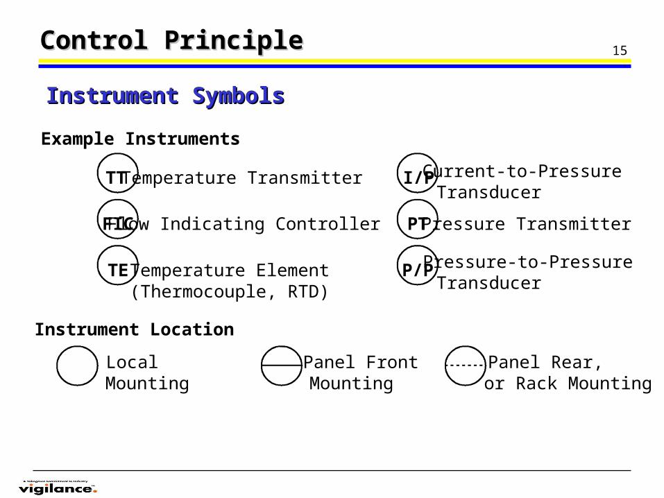
Example Instruments
TT
FIC
TE
Temperature Transmitter
Flow Indicating Controller
Temperature Element(Thermocouple, RTD)
I/P Current-to-PressureTransducer
Pressure Transmitter
Pressure-to-PressureTransducer
PT
P/P
LocalMounting
Panel FrontMounting
Panel Rear,or Rack Mounting
Instrument Location
Instrument SymbolsInstrument Symbols
Control PrincipleControl Principle
16
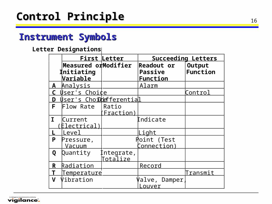
First Letter Succeeding LettersMeasured orInitiatingVariable
Modifier Readout orPassiveFunction
OutputFunction
A Analysis AlarmC User's Choice ControlD User's Choice DifferentialF Flow Rate Ratio
(Fraction)I Current
(Electrical)Indicate
L Level LightP Pressure,
VacuumPoint (TestConnection)
Q Quantity Integrate,Totalize
R Radiation RecordT Temperature TransmitV Vibration Valve, Damper,
Louver
Letter Designations
Instrument SymbolsInstrument Symbols
Control PrincipleControl Principle
17
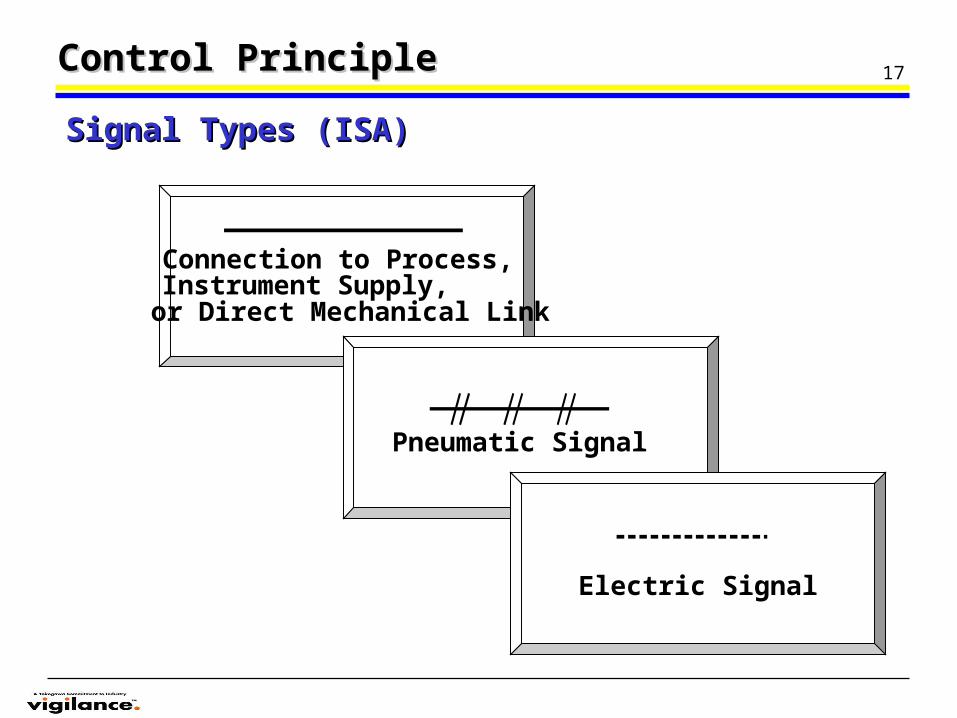
Connection to Process,Instrument Supply, or Direct Mechanical Link
Pneumatic Signal
Electric Signal
Signal Types (ISA)Signal Types (ISA)
Control PrincipleControl Principle
18Control PrincipleControl Principle
• Pneumatic• Analog• Digital
– Single Loop Controllers– Distributed Control System– Fieldbus Control System
Controller TypesController Types
19
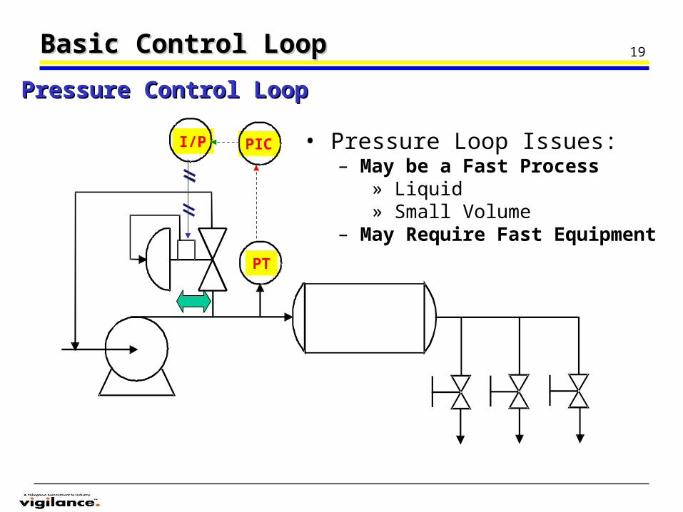
I/P
PT
PIC • Pressure Loop Issues:– May be a Fast Process
» Liquid» Small Volume
– May Require Fast Equipment
Basic Control LoopBasic Control Loop
Pressure Control LoopPressure Control Loop
20
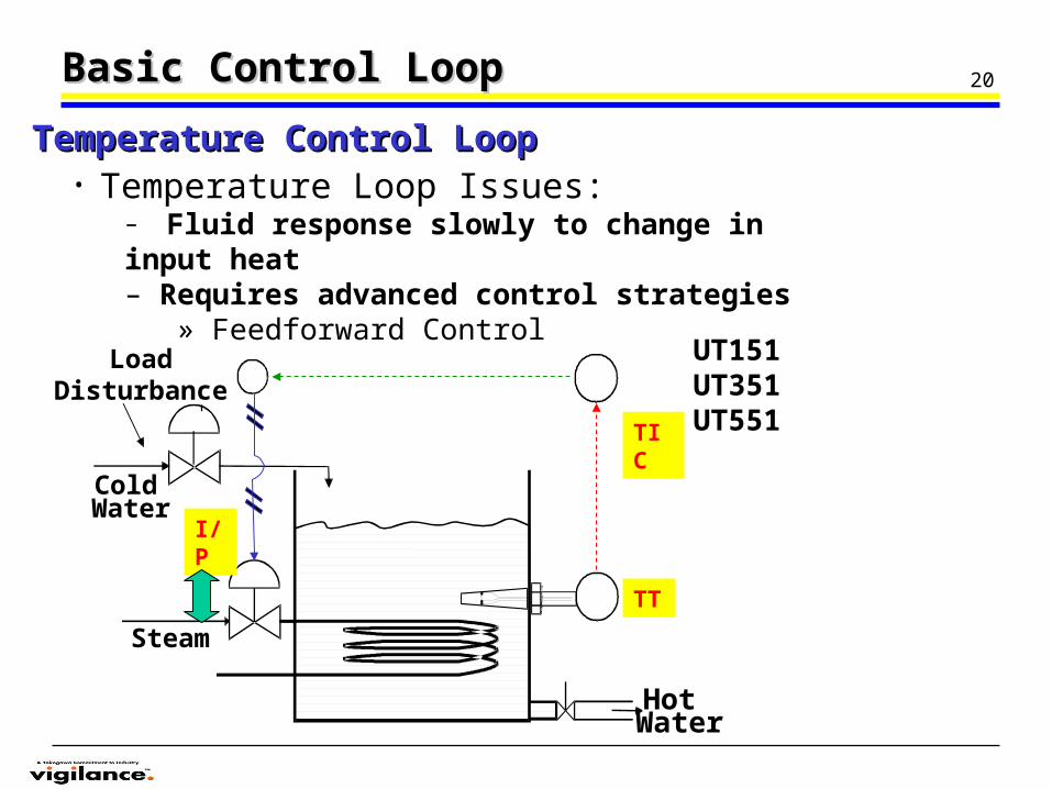
Steam
ColdWater
HotWater
Load Disturbance
Basic Control LoopBasic Control Loop
Temperature Control LoopTemperature Control Loop• Temperature Loop Issues:
– Fluid response slowly to change in input heat– Requires advanced control strategies
» Feedforward Control
TT
TIC
I/P
UT151UT351UT551
21
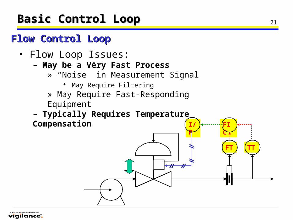
I/P FIC
TTFT
Basic Control LoopBasic Control Loop
Flow Control LoopFlow Control Loop
• Flow Loop Issues:– May be a Very Fast Process
» “Noise” in Measurement Signal• May Require Filtering
» May Require Fast-Responding Equipment– Typically Requires Temperature Compensation
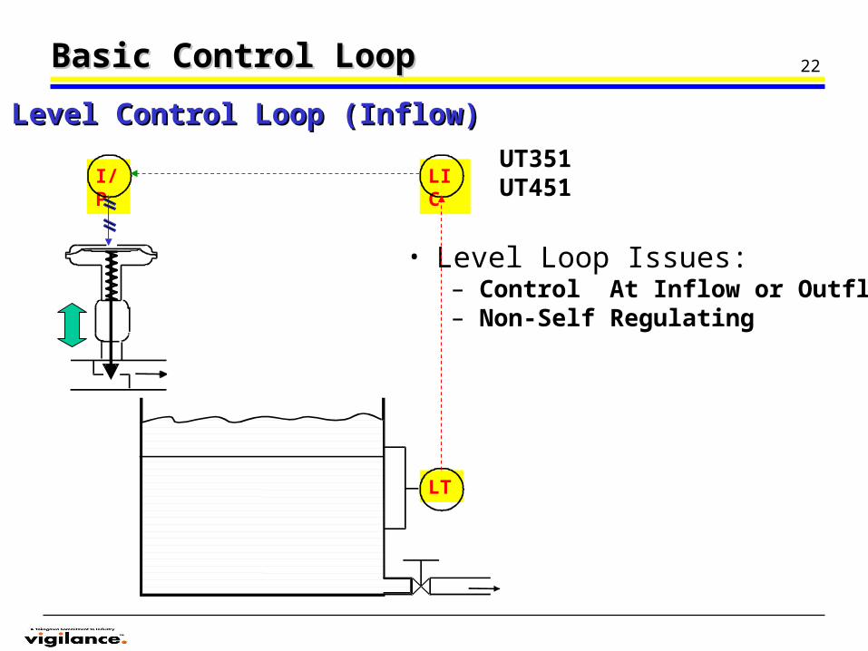
22
I/P LIC
LT
Basic Control LoopBasic Control Loop
Level Control Loop (Inflow)Level Control Loop (Inflow)
• Level Loop Issues:– Control At Inflow or Outflow– Non-Self Regulating
UT351UT451
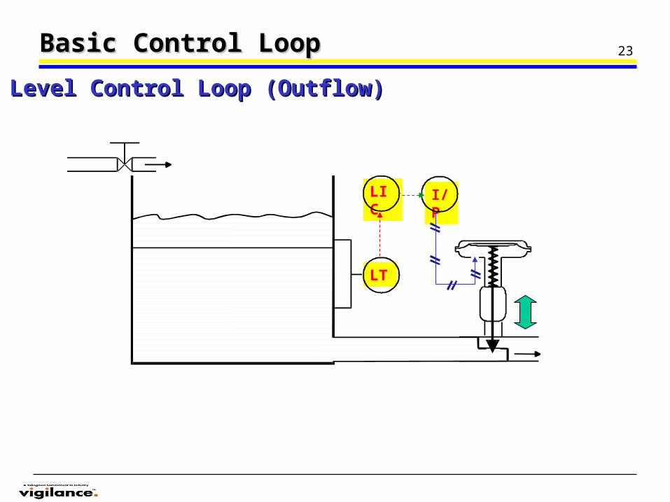
23
I/PLIC
LT
Basic Control LoopBasic Control Loop
Level Control Loop (Outflow)Level Control Loop (Outflow)
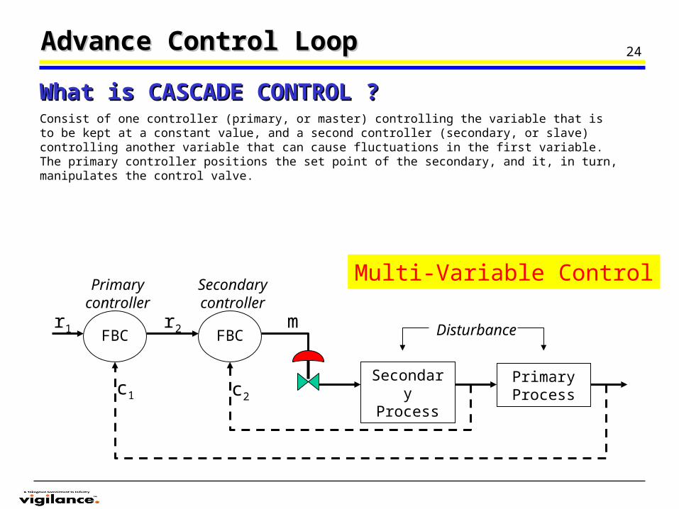
24Advance Control LoopAdvance Control Loop
Consist of one controller (primary, or master) controlling the variable that is to be kept at a constant value, and a second controller (secondary, or slave) controlling another variable that can cause fluctuations in the first variable. The primary controller positions the set point of the secondary, and it, in turn, manipulates the control valve.
What is CASCADE CONTROL ?What is CASCADE CONTROL ?
FBC FBC
Secondary Process
Primary Process
Secondary controller
Primary controller
Disturbancer1 r2 m
c1 c2
Multi-Variable Control
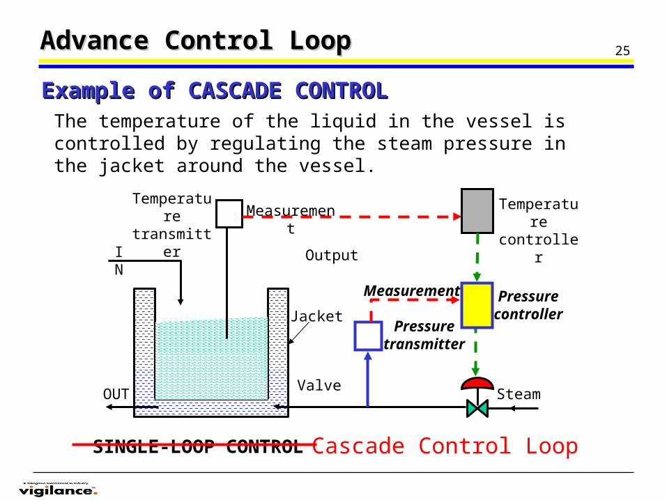
25Advance Control LoopAdvance Control Loop
Example of CASCADE CONTROLExample of CASCADE CONTROLThe temperature of the liquid in the vessel is controlled by regulating the steam pressure in the jacket around the vessel.
Temperature transmitter
Temperature controller
Measurement
Output
SteamValve
Jacket
IN
OUT
SINGLE-LOOP CONTROL
Pressure transmitter
Measurement Pressure controller
Cascade Control Loop
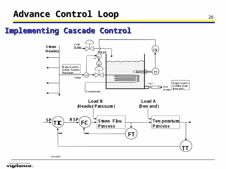
26Advance Control LoopAdvance Control Loop
Implementing Cascade Control Implementing Cascade Control
27
Level indicating controller
Flow controller
Boiler
FeedwaterFT
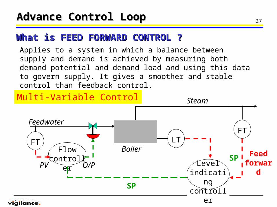
Applies to a system in which a balance between supply and demand is achieved by measuring both demand potential and demand load and using this data to govern supply. It gives a smoother and stable control than feedback control.
Advance Control LoopAdvance Control Loop
What is FEED FORWARD CONTROL ?What is FEED FORWARD CONTROL ?
FT LT
Steam
SP
PV O/P
Multi-Variable Control
Feed forwar
d
SP
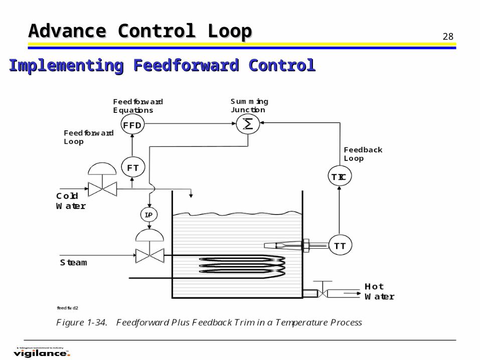
28Advance Control LoopAdvance Control Loop
Implementing Feedforward ControlImplementing Feedforward Control
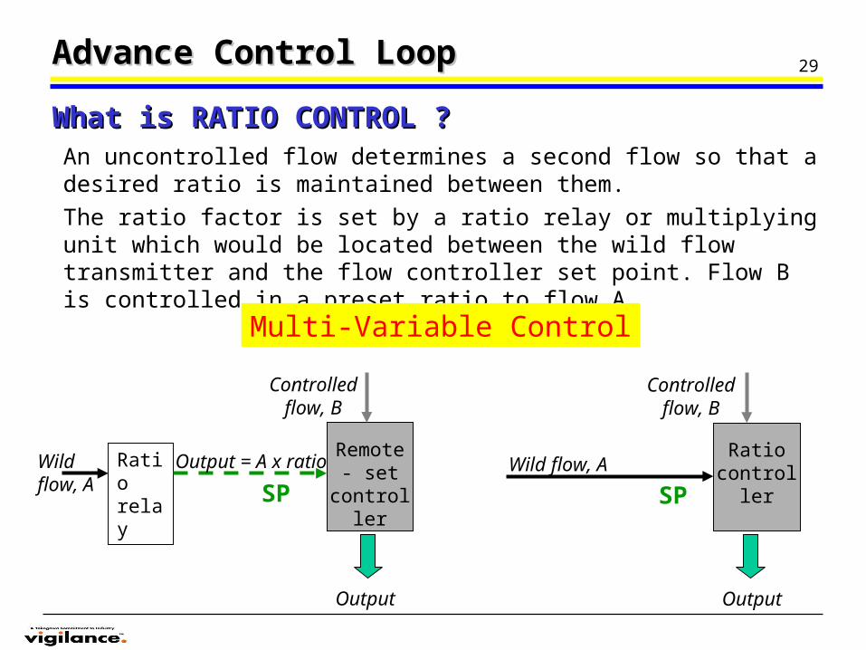
29
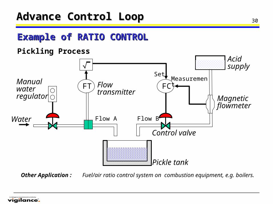
An uncontrolled flow determines a second flow so that a desired ratio is maintained between them.
The ratio factor is set by a ratio relay or multiplying unit which would be located between the wild flow transmitter and the flow controller set point. Flow B is controlled in a preset ratio to flow A.
Advance Control LoopAdvance Control Loop
What is RATIO CONTROL ?What is RATIO CONTROL ?
Ratio relay
Wild flow, A
Controlled flow, B
Remote - set
controller
Output = A x ratio
SP
Output
Wild flow, A
Controlled flow, B
Ratio controller
Output
Multi-Variable Control
SP
30Advance Control LoopAdvance Control Loop
Example of RATIO CONTROLExample of RATIO CONTROL
Other Application : Fuel/air ratio control system on combustion equipment, e.g. boilers.
Acid supply
Magnetic flowmeter
Pickle tank
Flow transmitter
FT FC
Control valve
Flow BFlow AWater
Manual water regulator
MeasurementSet
Pickling Process
31
O/P
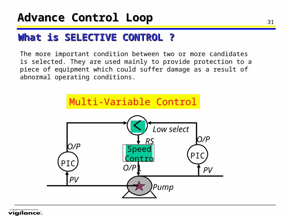
The more important condition between two or more candidates is selected. They are used mainly to provide protection to a piece of equipment which could suffer damage as a result of abnormal operating conditions.
Advance Control LoopAdvance Control Loop
What is SELECTIVE CONTROL ?What is SELECTIVE CONTROL ?
Speed Control
PICPIC
RS
Low select
PV
Pump
O/PO/P
PV
Multi-Variable Control
32Control AlgorithmControl Algorithm
• On/Off On/Off
• Multi-stepMulti-step
• ProportionalProportional
• IntegralIntegral
• DerivativeDerivative
33Control AlgorithmControl Algorithm
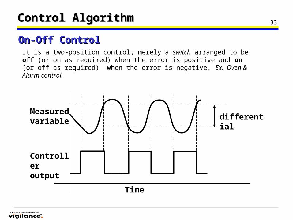
It is a two-position control, merely a switch arranged to be off (or on as required) when the error is positive and on (or off as required) when the error is negative. Ex.. Oven & Alarm control.
On-Off ControlOn-Off Control
differentialMeasured variable
Controller output
Time
34
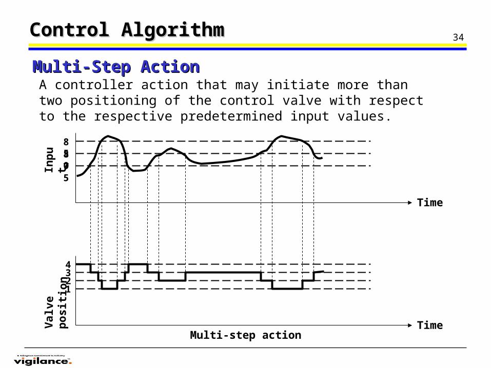
A controller action that may initiate more than two positioning of the control valve with respect to the respective predetermined input values.
Control AlgorithmControl Algorithm
Multi-Step ActionMulti-Step Action
Multi-step actionTime
Time
Val
ve p
osi
tio
nIn
pu
t
1234
75
80
85
35
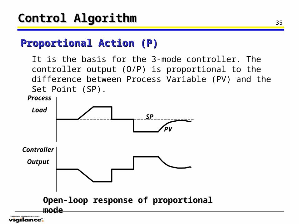
It is the basis for the 3-mode controller. The controller output (O/P) is proportional to the difference between Process Variable (PV) and the Set Point (SP).
Control AlgorithmControl Algorithm
Proportional Action (P)Proportional Action (P)
Process
Load
Controller
Output
SP
PV
Open-loop response of proportional mode
36Control AlgorithmControl Algorithm
Proportional Action (P)Proportional Action (P)
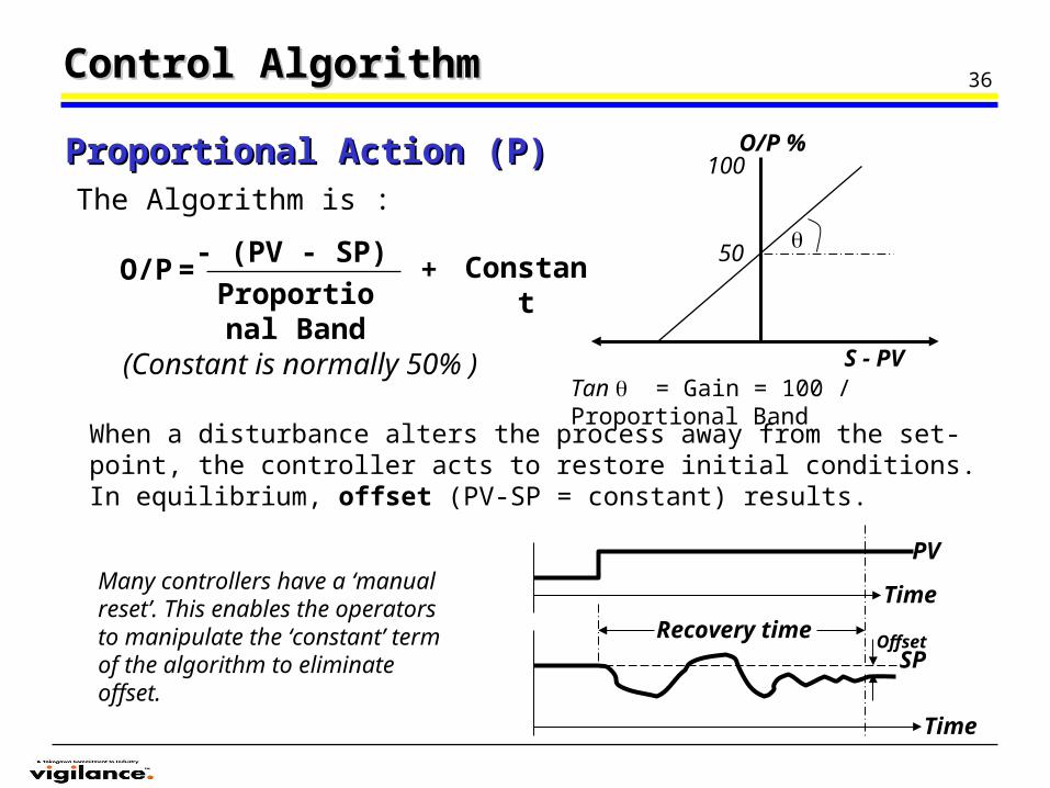
When a disturbance alters the process away from the set-point, the controller acts to restore initial conditions. In equilibrium, offset (PV-SP = constant) results.
The Algorithm is :
O/P- (PV - SP)Proportional Band
Constant
= +
S - PV
O/P %100
(Constant is normally 50% )
50
Tan = Gain = 100 / Proportional Band
Time
SP
Time
Recovery timeOffset
Many controllers have a ‘manual reset’. This enables the operators to manipulate the ‘constant’ term of the algorithm to eliminate offset.
PV
37Control AlgorithmControl Algorithm
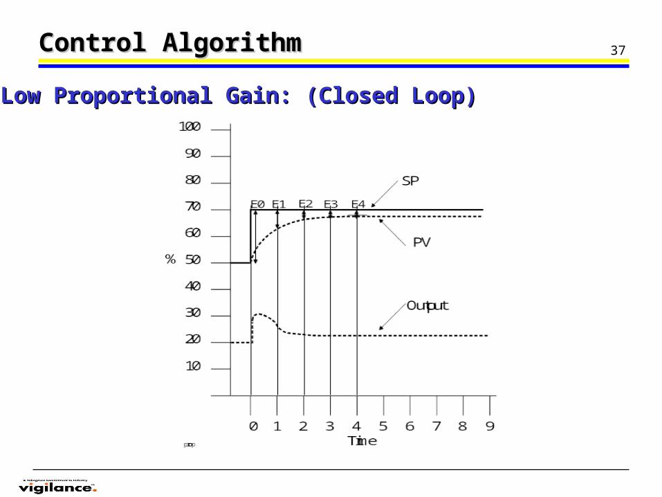
Low Proportional Gain: (Closed Loop)Low Proportional Gain: (Closed Loop)

38Control AlgorithmControl Algorithm
High Proportional Gain: (Closed Loop)High Proportional Gain: (Closed Loop)
39
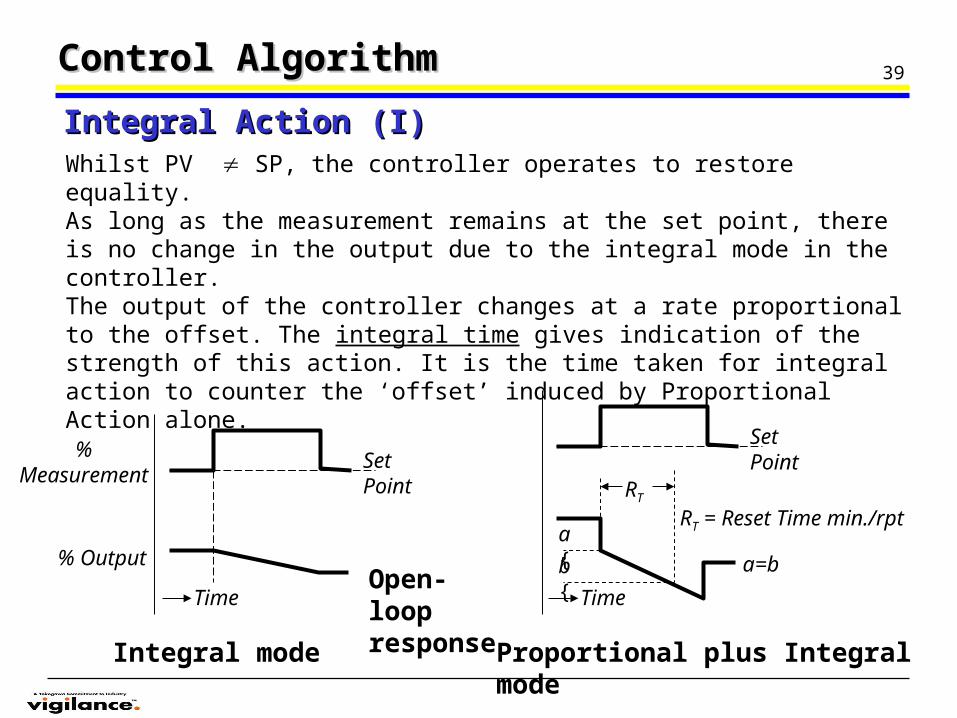
Whilst PV SP, the controller operates to restore equality.As long as the measurement remains at the set point, there is no change in the output due to the integral mode in the controller.The output of the controller changes at a rate proportional to the offset. The integral time gives indication of the strength of this action. It is the time taken for integral action to counter the ‘offset’ induced by Proportional Action alone.
Control AlgorithmControl Algorithm
Integral Action (I)Integral Action (I)
Time
Set Point
% Measurement
% Output
Time
Set Point
a=b
RT
RT = Reset Time min./rpta {
b {
Integral mode Proportional plus Integral mode
Open-loop response
40Control AlgorithmControl Algorithm
0 1 2 3 4 5 6 7 8 9Time
100
90
80
70
60
50
40
30
20
10
%
SP
PV
ProportionalPlus Integral
Output
ProportionalResponse
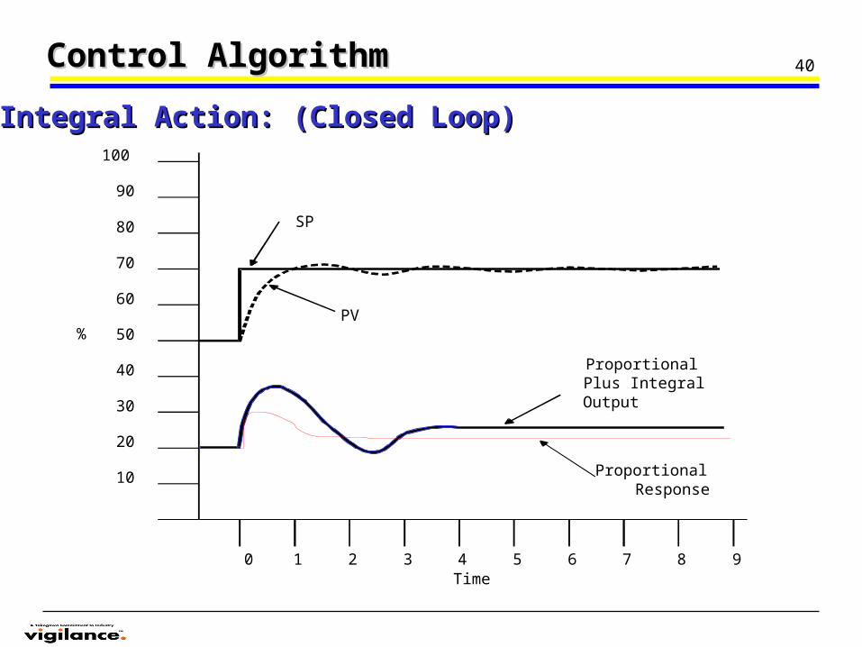
Integral Action: (Closed Loop)Integral Action: (Closed Loop)
41
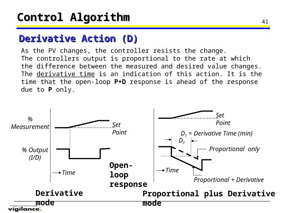
As the PV changes, the controller resists the change.The controllers output is proportional to the rate at which the difference between the measured and desired value changes.The derivative time is an indication of this action. It is the time that the open-loop P+D response is ahead of the response due to P only.
Control AlgorithmControl Algorithm
Derivative Action (D)Derivative Action (D)
Time
Set Point
% Measurement
% Output (I/D)
Derivative mode
Time
Set Point
DT
DT = Derivative Time (min)
Proportional plus Derivative mode
Open-loop response
Proportional + Derivative
Proportional only
42
0 1 2 3 4 5 6 7 8 9Time
100
90
80
70
60
50
40
30
20
10
%
SP
PV PID Output
Control AlgorithmControl Algorithm
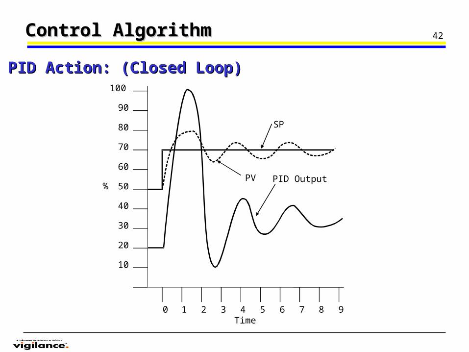
PID Action: (Closed Loop)PID Action: (Closed Loop)
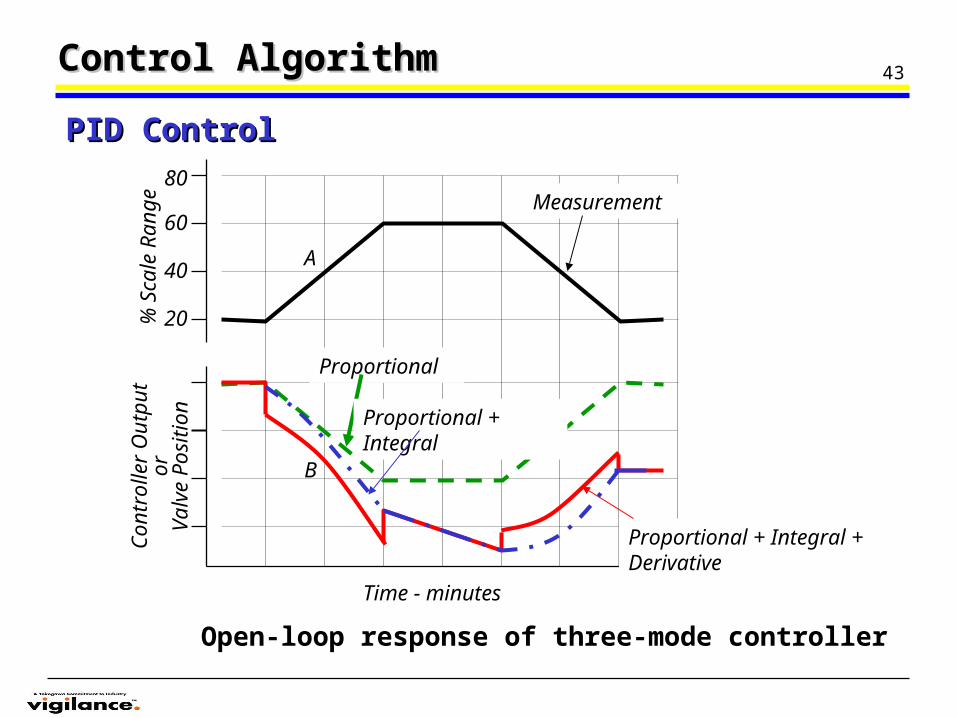
43Control AlgorithmControl Algorithm
PID ControlPID Control
A
B
80
60
40
20% S
cale
Ran
geC
ontr
olle
r O
utpu
tor
Val
ve P
ositi
onMeasurement
Proportional
Time - minutes
Open-loop response of three-mode controller
Proportional + Integral + Derivative
Proportional + Integral
44
I/P
PT
PIC
P
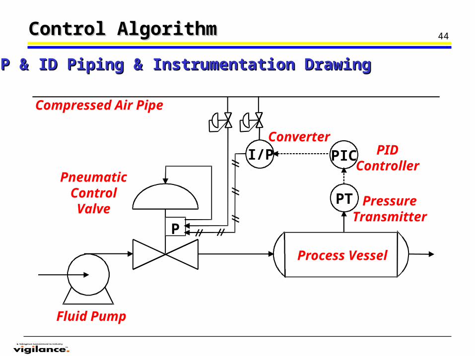
Control AlgorithmControl Algorithm
P & ID Piping & Instrumentation DrawingP & ID Piping & Instrumentation Drawing
Process Vessel
Fluid Pump
PneumaticControlValve
Compressed Air Pipe
ConverterPID
Controller
PressureTransmitter
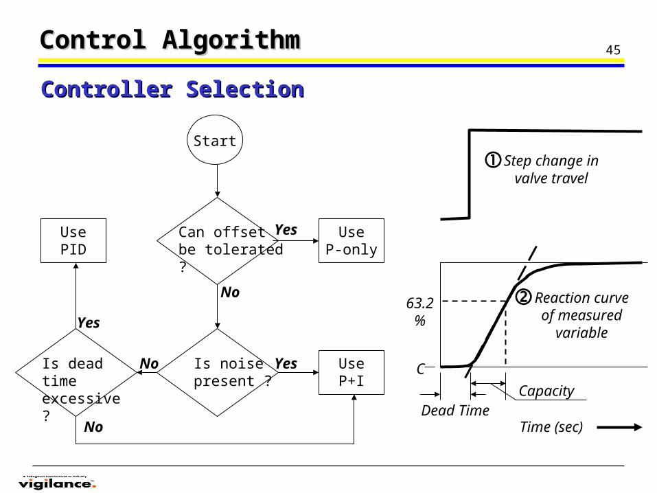
45Control AlgorithmControl Algorithm
Controller SelectionController Selection
Can offset be tolerated ?
Start
UseP-only
Yes
UseP+I
Yes
No
Is dead time excessive ?
No
UsePID
Yes
Is noise present ?
No Reaction curve of measured
variable
CapacityDead Time
C
63.2%
Time (sec)
Step change in valve travel
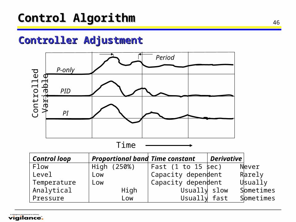
46Control AlgorithmControl Algorithm
Controller AdjustmentController Adjustment
Time
Co
ntr
olle
d V
ari
abl
e Period
P-only
PID
PI
Control loop Proportional band Time constant DerivativeFlow High (250%) Fast (1 to 15 sec) NeverLevel Low Capacity dependent RarelyTemperature Low Capacity dependent UsuallyAnalytical High Usually slow SometimesPressure Low Usually fast Sometimes
47
An automatic control scheme in which the controller is programmed to evaluate its own effectiveness and modify its own control parameters to respond to dynamic conditions occurring in or to the process which affect the controlled variables.
Control SystemControl System
Adaptive ControlAdaptive Control
Ex) Digital Controller- Sensors are run to the computer’s input. - Servomechanisms are connected to the computer’s output.- Future changes don’t require re-wiring.- Changing control functions (P,I, and D) and configurations (between cascade mode and feedforward mode) will be made on the computer’s program and not necessarily to any hardware.
48Control SystemControl System
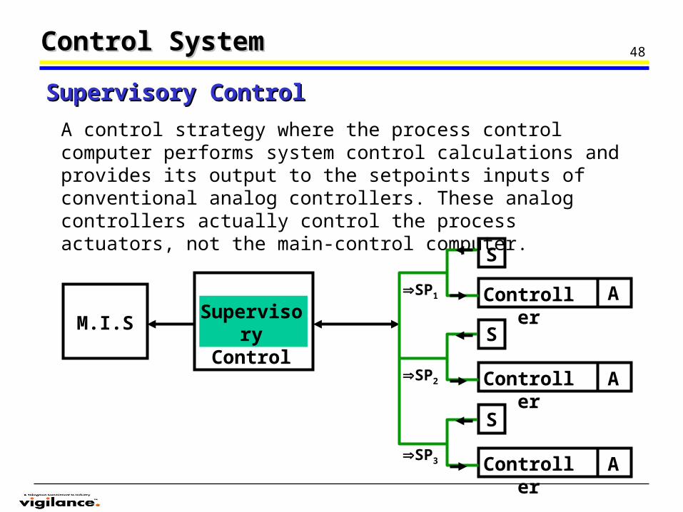
A control strategy where the process control computer performs system control calculations and provides its output to the setpoints inputs of conventional analog controllers. These analog controllers actually control the process actuators, not the main-control computer.
Supervisory ControlSupervisory Control
M.I.SSupervisory
Control
A
S
Controller
S
AController
S
AController
SP1
SP2
SP3
49
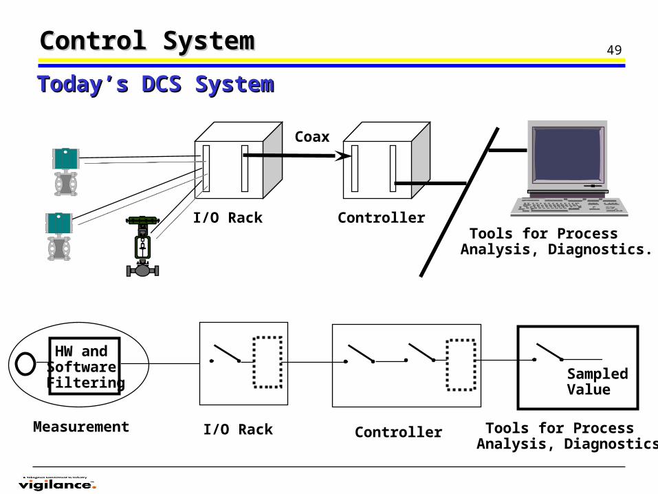
Measurement
HW andSoftwareFiltering
I/O Rack
Coax
Controller Tools for Process Analysis, Diagnostics.
SampledValue
Tools for Process Analysis, Diagnostics.
Controller I/O Rack
Control SystemControl System
Today’s DCS SystemToday’s DCS System
50Control SystemControl System
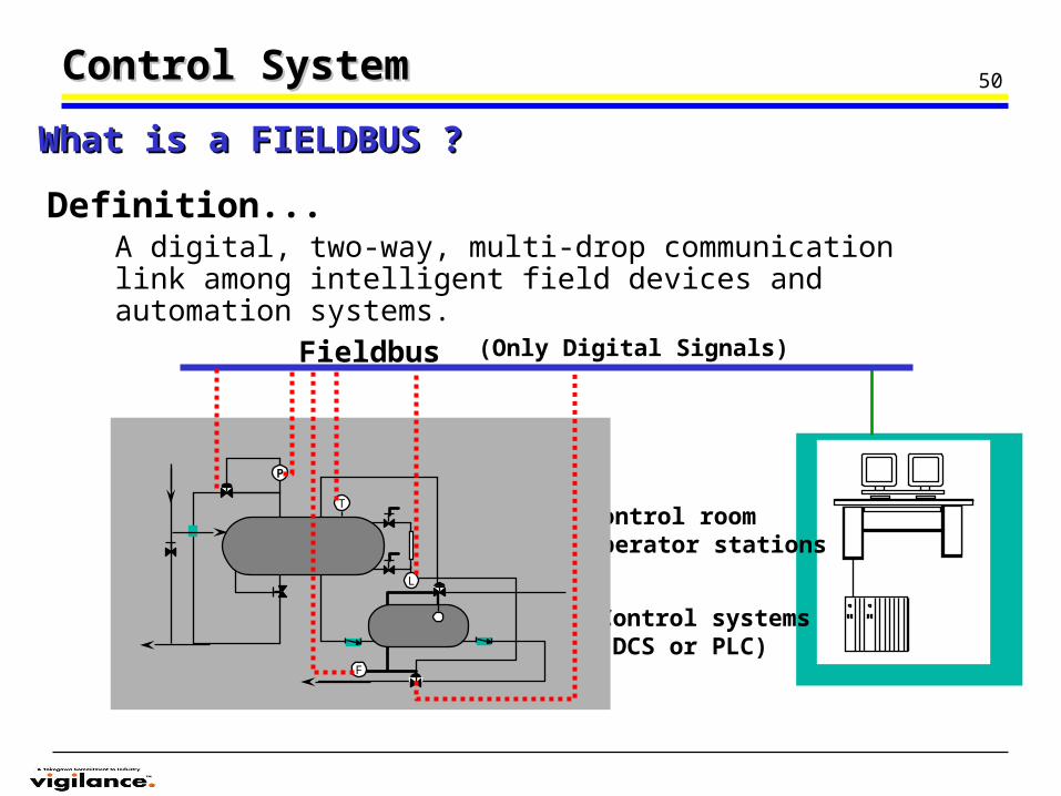
Definition...
Control roomoperator stations
Control systems(DCS or PLC)
A digital, two-way, multi-drop communication link among intelligent field devices and automation systems.
Fieldbus (Only Digital Signals)
What is a FIELDBUS ?What is a FIELDBUS ?
P
T
L
F
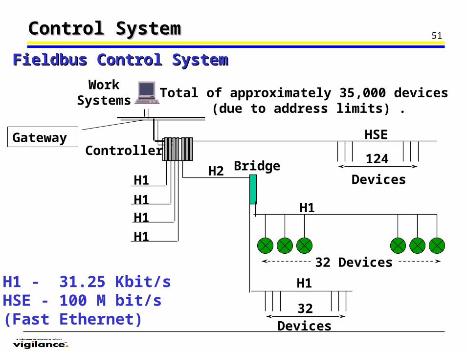
51
Gateway HSE
H1
H1H1
H1
BridgeH2
H1
H1
124
Devices
Work Systems
H1 - 31.25 Kbit/sHSE - 100 M bit/s(Fast Ethernet)
(due to address limits) .Total of approximately 35,000 devices
Fieldbus Control SystemFieldbus Control System
Controller
32 Devices
32Devices
Control SystemControl System
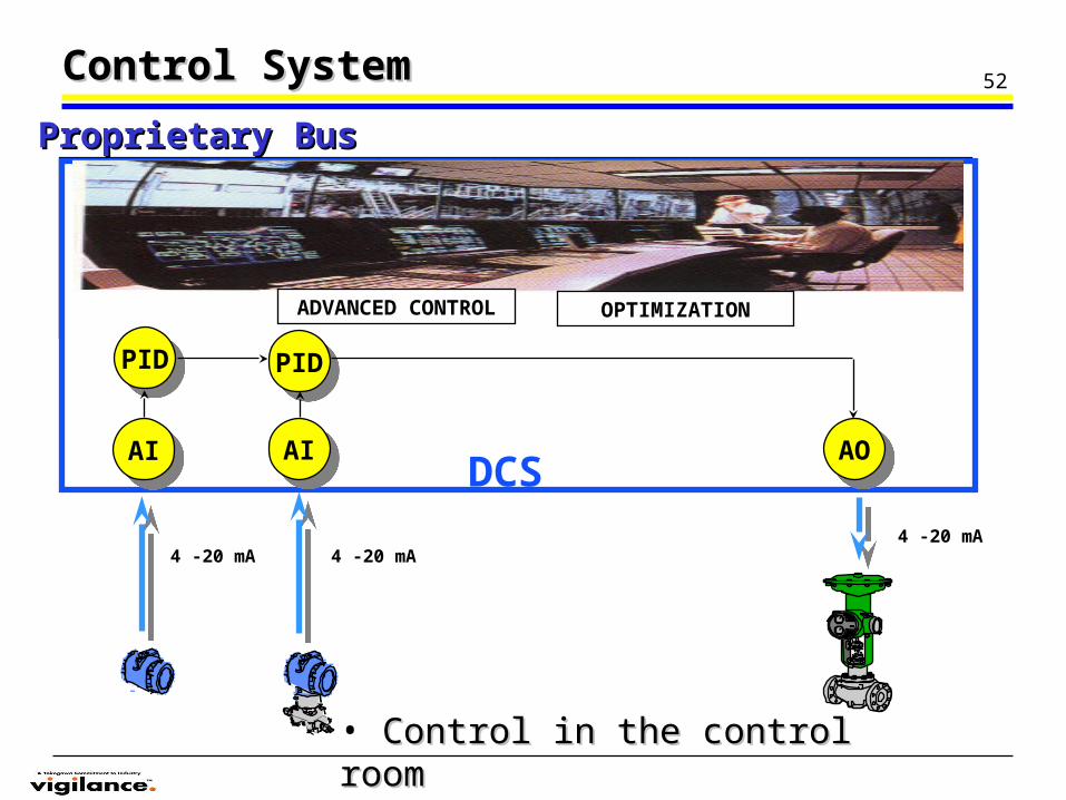
52Control SystemControl System
AIAI
PIDPID
AIAI AOAO
PIDPID
DCS
4 -20 mA 4 -20 mA4 -20 mA
ADVANCED CONTROL OPTIMIZATION
• Control in the control roomControl in the control room
Proprietary BusProprietary Bus
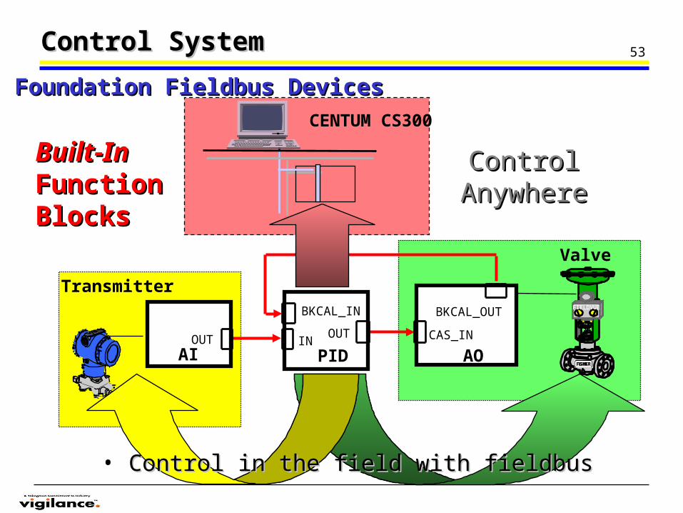
53
PID IN
OUT
BKCAL_IN FIELDVUE
AO
BKCAL_OUT
CAS_IN
AIOUT
CENTUM CS300
Valve
Transmitter
Control SystemControl System
Control Control AnywhereAnywhere
Built-InBuilt-InFunction Function BlocksBlocks
Foundation Fieldbus DevicesFoundation Fieldbus Devices
• Control in the field with fieldbusControl in the field with fieldbus
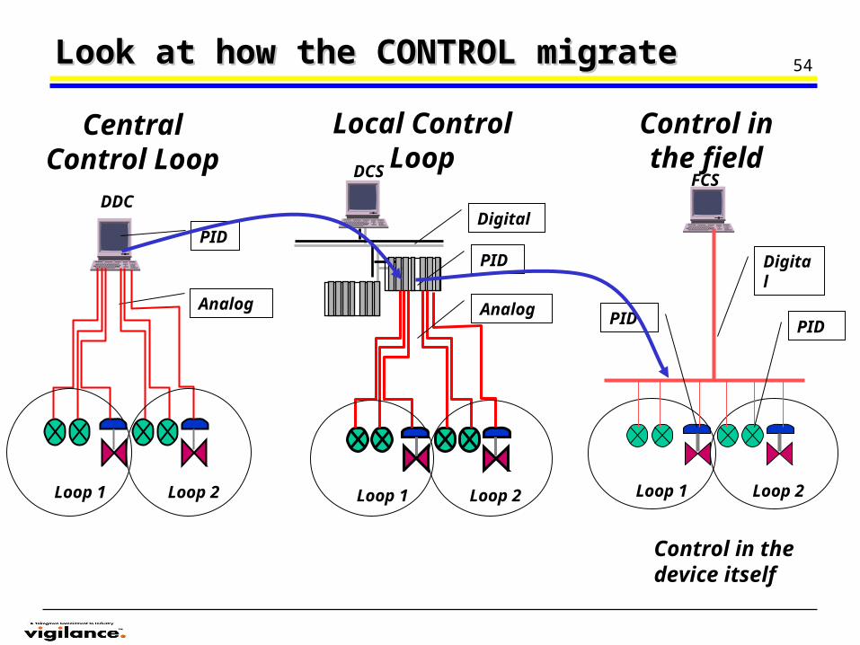
54
FCS
Loop 1 Loop 2
Digital
PID PID
DCS
Loop 1 Loop 2
Digital
PID
Analog
DDC
Analog
PID
Loop 1 Loop 2
Central Control Loop
Local Control Loop
Control in the field
Control in the device itself
Look at how the CONTROL migrate Look at how the CONTROL migrate
55ExerciseExercise
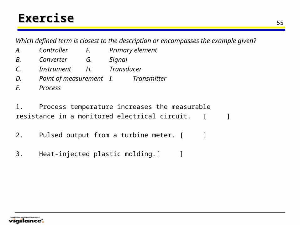
Which defined term is closest to the description or encompasses the example given?
A. Controller F. Primary element
B. Converter G. Signal
C. Instrument H. Transducer
D. Point of measurement I. Transmitter
E. Process
1. Process temperature increases the measurable
resistance in a monitored electrical circuit. [ ]
2. Pulsed output from a turbine meter. [ ]
3. Heat-injected plastic molding. [ ]
56ExerciseExercise
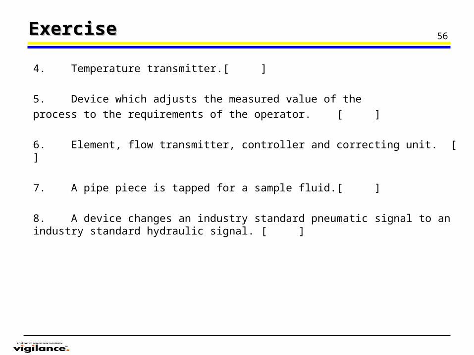
4. Temperature transmitter. [ ]
5. Device which adjusts the measured value of the
process to the requirements of the operator. [ ]
6. Element, flow transmitter, controller and correcting unit. [ ]
7. A pipe piece is tapped for a sample fluid. [ ]
8. A device changes an industry standard pneumatic signal to an industry standard hydraulic signal. [ ]
57ExerciseExercise
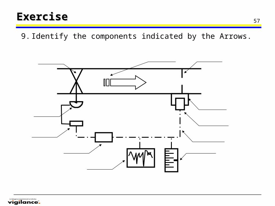
9. Identify the components indicated by the Arrows.
58ExerciseExercise
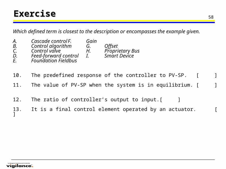
Which defined term is closest to the description or encompasses the example given.
A. Cascade control F. GainB. Control algorithm G. OffsetC. Control valve H. Proprietary BusD. Feed-forward control I. Smart Device E. Foundation Fieldbus
10. The predefined response of the controller to PV-SP. [ ]
11. The value of PV-SP when the system is in equilibrium. [ ]
12. The ratio of controller’s output to input. [ ]
13. It is a final control element operated by an actuator. [ ]
59ExerciseExercise
14. Involves master & slave controllers. [ ]
15. The output of the loop drives the input. [ ]
16. A digital communication based control network with control action in the controller only. [ ]
17. A digital communication based control network that allow control in the field. [ ]
18. A device that provide both analog & communication signal in its loop wire pair. [ ]