Embed Size (px)
Citation preview

CONTROL RECTIFIER FOR VARIABLE SPEED SINGLE PHASE
DC MOTOR
MOHD HELMI BIN SAMTA
This thesis is submitted as partial fulfillment of the
requirements for the award of the
Bachelor Degree of Electrical Engineering (Power Systems)
Faculty of Electrical & Electronics Engineering Universiti Malaysia Pahang
MAY 2008

ii
“All the trademark and copyrights use herein are property of their respective owner.
References of information from other sources are quoted accordingly; otherwise the
information presented in this report is solely work of the author.”
Signature : ____________________________
Author : MOHD HELMI BIN SAMTA
Date : 8 MAY 2008

iii
To my beloved mother, father, and brothers

“I hereby acknowledge that the scope and quality of this thesis is qualified for the
award of the Bachelor Degree of Electrical Engineering (Power System)”
Signature : ______________________________________________
Name : MR.MUHAMAD ZAHIM B SUJOD
Date : 8 MAY 2008

iv
ACKNOWLEDGEMENT
First and foremost, I would like to thank God the Almighty for his bless
towards myself. Without his blessing I might not be able to complete my final year
project entitled “Control Rectifier for Variable Speed Single DC Motor”. I able to
complete this research project in time as a partial fulfillment of the requirement of the
degree of Bachelor Electrical Engineering (Power System).
Secondly, I would also like to take this opportunity to thank all the people who
had assisted me directly and indirectly in completing the project. My first gratitude goes
to Mr. Muhamad Zahim bin Sujod, my one and only supervisor for the project whom
had given all the support, advice and guidance I might need. He had been guiding me
from the very start of the project until the final touch of the thesis write up. With his
helps, I had learned many things regarding the project, as well as extra knowledge that I
believe I would not have this sort of opportunity elsewhere. The project would
obviously not be successful without him. A million thanks to Mr. Muhamad Zahim bin
Sujod.
Very special thanks also to other friends who had guided and helped me a lot
with the project. Not to forget, I would also wish to thank all of my lecturers who had
given their full co-operation. They had never hesitated to share knowledge and opinions
in ensuring the project be completed successfully.
Last but not least, I would like to thank my beloved parents who had given me a
lot of moral support while I was struggling with this project.

v
ABSTRACT
An electric power can be converted from one form to another form by using
power electronics devices. The function of power electronics circuits by using
semiconductor devices as switch is modifying or controlling a voltage. The goal of
power electronics circuits are to convert electrical energy from one form to another,
from source to load with highest efficiency, high availability and high reliability with
the lowest cost, smallest size and weight. The term rectification refers to the power
circuit whose function is to alter the ac characteristic of the line electric power to
produce a “rectified”ac power at the load side that contain the dc value. In this project
task, the rectifier circuit should be possible to produce a variable average voltage by
controlling the delay. The single phase 240 Vrms AC source is stepped down to 12 Vrms
by using step-down power transformer. A versatile method of controlling the output of a
full-wave rectifier is to substitute controlled switches such as SCRs for the diodes. The
output is controlled by adjusting the delay angle of each SCR, resulting in an output
voltage or output current which is variable over a limited range with programmed the
microcontroller ( PIC16F84A ).
vi
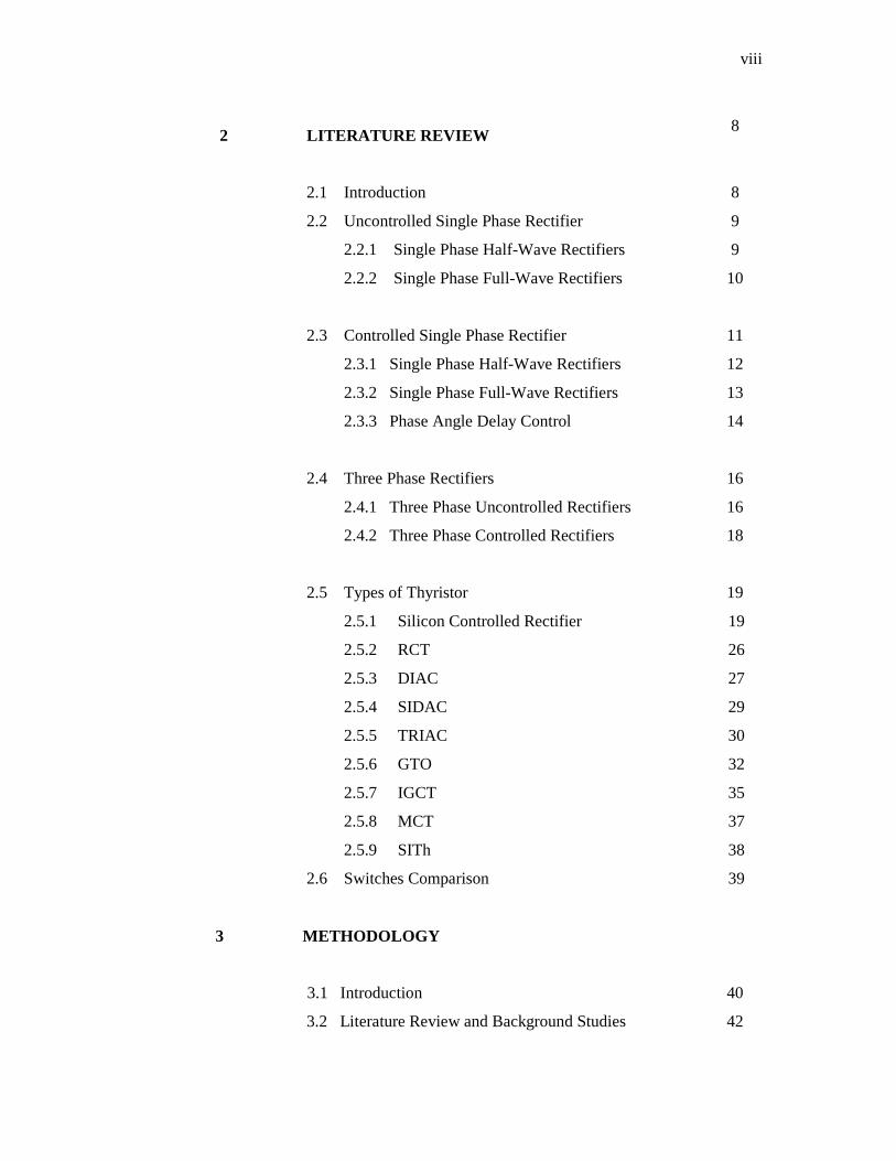
ABSTRAK
Kuasa eletrik boleh diubah daripada satu bentuk ke bentuk yang lain dengan
menggunakan litar peranti kuasa elektronik.Fungsi litar elektronik berkuasa dengan
menggunakan peranti semiconductor sebagai suis untuk mengawal dan mengubah arus
voltan.Matlamat litar elektronik berkuasa adalah untuk mengubah kuasa elektrik kepada
bentuk yang lain, daripada sumber kuasa kepada beban dengan tahap kecekapan yang
tertinggi, perihal boleh didapati yang tertinggi ,perihal yang dapat dipercayai tertinggi
dengan kos yang paling murah ,saiz dan berat yang paling kecil.Istilah rektifikasi
merujuk kepada litar kuasa yang berfungsi untuk mengubah ciri ac dalam “line” kuasa
elektrik untuk menghasilkan “rectified” ac pada beban yang mengandungi nilai dc
.Dalam tugasan projek ini, litar “rectifier” sepatutnya akan menghasilkan nilai purata
arus voltan yang berubah dengan mengawal kelambatan . Sumber kuasa satu fasa 240
Vrms, diturunkan kepada 12 Vrms dengan menggunakan “ step-down power
transformer”.Berbagai kaedah mengawal keluaran “full-wave rectifier” dengan
menggantikan diod kepada suis yang boleh dikawal iaitu SCR’s.Keluaran dikawal
dengan mengubah nilai “delay angle”setiap SCR’s ,yang mana nilai arus voltan atau
nilai arus adalah berubah pada lingkungan yang terhad dengan memprogram
mikropengawal ( PIC16F84A ).

vii
TABLE OF CONTENTS CHAPTER TITLE PAGE
DECLARATION OF THESIS’S STATUS
DECLARATION OF SUPERVISOR
TITLE
DECLARATION
DEDICATION
ii
iii
ACKNOWLEDGEMENT iv
ABSTRACT v
ABSTRAK vi
TABLE OF CONTENT vii
LIST OF TABLES ix
LIST OF FIGURES
LIST OF ABBREVIATIONS
xi
xiv
LIST OF SYMBOLS xv
LIST OF APPENDICES xvi
1 INTRODUCTION 1
1.1 Overview 1
1.2 Background 3
1.3 Objectives 5
1.4 Scopes 5
1.5 Problem Statement
1.6 Thesis Organization
6
7
viii
2 LITERATURE REVIEW
8
2.1 Introduction 8
2.2 Uncontrolled Single Phase Rectifier
2.2.1 Single Phase Half-Wave Rectifiers
2.2.2 Single Phase Full-Wave Rectifiers
9
9
10
2.3 Controlled Single Phase Rectifier
2.3.1 Single Phase Half-Wave Rectifiers
2.3.2 Single Phase Full-Wave Rectifiers
2.3.3 Phase Angle Delay Control
11
12
13
14
2.4 Three Phase Rectifiers
2.4.1 Three Phase Uncontrolled Rectifiers
2.4.2 Three Phase Controlled Rectifiers
16
16
18
2.5 Types of Thyristor
2.5.1 Silicon Controlled Rectifier
2.5.2 RCT
2.5.3 DIAC
2.5.4 SIDAC
2.5.5 TRIAC
2.5.6 GTO
2.5.7 IGCT
2.5.8 MCT
2.5.9 SITh
2.6 Switches Comparison
19
19
26
27
29
30
32
35
37
38
39
3 METHODOLOGY
3.1 Introduction
3.2 Literature Review and Background Studies
40
42

ix
3.3 Theoretical Design
3.3.1 Input
3.3.2 Power Transformer
3.3.3 Silicon Control Rectifier (SCR)
3.3.4 Power Processor Converter
3.3.5 Pulse Transformer as an Driver Circuit
3.3.6 PIC as the Controller Circuit
3.3.7 DC Motor as a Load
3.4 Software Development
3.5 Hardware Development and Software Tested
4 RESULT & ANALYSIS
4.1 Introduction
4.2 Design Philosophy
4.3 Hand Calculation For Controlled Full-Wave Rectifier
4.3.1 Calculation for Delay Angle of 0˚
4.3.2 Calculation for Delay Angle of 30˚
4.3.3 Calculation for Delay Angle of 60˚
4.3.4 Calculation for Delay Angle of 90˚
4.3.5 Calculation for Delay Angle of 120˚
4.3.6 Calculation for Delay Angle of 150˚
4.3.7 Calculation for Delay Angle of 180˚
4.4 OrCAD Pspice Simulation
4.5 Output Waveform
4.6 Comparison Result
4.6.1 Comparison Results For 3 Delay Angle
4.6.2 Graph For 3 Delay Angle
4.7 Efficiency of the Project
4.8 Software Development
4.9 Hardware Design
4.10 Costing
43
43
44
45
47
50
54
58
60
60
61
61
61
62
62
63
63
64
64
65
65
67
74
81
82
83
85
87
92
93

x
4.11 Potential of Commercialization
5 CONCLUSION & FUTURE WORK
5.1 Summary of the Project
5.2 Future Recommendation
94
95
95
96
REFERENCES 97
APPENDIX A
98-100

ix
LIST OF TABLES
TABLE NO. TITLE PAGE Table 2.1 Switches Comparison 39
Table 4.1 Comparison Results 81
Table 4.2 Comparison Results For 3 Delay Angle 82
Table 4.3 Cost of Components 90

xi
LIST OF FIGURES
FIGURE NO. TITLE PAGE
1.1 Four Types of Conversion 2
1.2 Power Processor & Controller 4
2.1 Single Phase Half-Wave Rectifier 10
2.2 The Bridge Rectifier 10
2.3 The Center-Tapped Transformer Rectifier 11
2.4 A Basic Half-Wave Controlled Rectifier 12
2.5 A Basic Full-Wave Controlled Bridge Rectifier 13
2.6 Circuit Modes 15
2.7 Possible Output Voltage waveform For SCR Bridge 15
2.8 The Three Phase Full-Bridge Uncontrolled Rectifier 17
2.9 Source and Output Voltage 17
2.10 The Three Phase Full-Bridge Controlled Rectifier 18
2.11 Thyristor 20
2.12 Layer Diagram of Thyristor 20
2.13 V - I Characteristics 22
2.14 A bank of six, 2000 A Thyristors (white pucks) 23
2.15 Symbol of DIAC 27
2.16 Typical Diac voltage and current relationships 28
2.17 Symbol of SIDAC 29
2.18 Triac Schematic Symbol 30
2.19 Triac semiconductor construction 31
2.20 Comparison of an SCR and GTO of same rating 33
2.21 Circuit symbol for an IGCT 35

xii
3.1 Flow Chart of Project Development 41
3.2 A Single Phase Controlled Rectifier Block Diagram 42
3.3 Connection 240 VAC to Power Transformer 43
3.4 Power Transformer 44
3.5 SCR TYN812 47
3.6 A Single Phase Controlled Bridge Rectifier 48
3.7 Triggering SCR2 and SCR4 as a pair 49
3.8 Controlled Bridge Rectifier 50
3.9 Pulse Transformer 52
3.10 Pulse Transformers as a Coupler for a Triggering Circuit to the
Gate and Cathode of an SCR 52
3.11 The Gate Connections for Two SCRs 53
3.12 Pulse Transformers as Interface Circuit 54
3.13 Schematic of PIC Connection 56
3.14 DIP Switch Connection 57
3.15 Control Unit Circuit 57
3.16 DC Motor 58
3.17 Parts of an Electric Motor 59
4.1 Alfa Vs Voltage output 66
4.2 Simulation with Delay Angle of 0˚ 67
4.3 Simulation with Delay Angle of 30˚ 68
4.4 Simulation with Delay Angle of 60˚ 69
4.5 Simulation with Delay Angle of 90˚ 70
4.6 Simulation with Delay Angle of 120˚ 71
4.7 Simulation with Delay Angle of 150˚ 72
4.8 Simulation with Delay Angle of 180˚ 73
4.9 Controlled Rectifier Waveform with Delay Angle of 0˚ 74
4.10 Controlled Rectifier Waveform with Delay Angle of 30˚ 74
4.11 Controlled Rectifier Waveform with Delay Angle of 60˚ 75
4.12 Controlled Rectifier Waveform with Delay Angle of 90˚ 75
4.13 Controlled Rectifier Waveform with Delay Angle of 120˚ 76
4.14 Controlled Rectifier Waveform with Delay Angle of 150˚ 76
4.15 Controlled Rectifier Waveform with Delay Angle of 180˚ 77
4.16 Waveform after step-down by transformer (12 Vrms) 78

xiii
4.17 Vac after step down by transformer (12Vrms) 78
4.18 Waveform at Alfa 60 degree 79
4.19 Hardware of PIC to program Delay angle 79
4.20 Waveform at Alfa 90 degree 80
4.21 Waveform at Alfa 120 degree 80
4.22 Graph for Theoretical 83
4.23 Graph for Simulation 83
4.24 Graph for Hardware 83
4.25 Controlled Rectifier For Variable Speed Single Phase DC Motor 89

xiv
LIST OF ABBREVIATIONS
AC - Alternate Current
DC - Direct Current
SCR - Silicon Control Rectifier
PIC - Programmable Intelligent Computer
IC - Integrated Circuit
LCD - Liquid Crystal Display
RCT - Reverse Conducting Thyristor
DIAC - Diode for Alternating Current
SIDAC - Silicon Diode for Alternating Current
TRIAC - Triode for Alternating Current
GTO - Gate Turn-Off Thyristor
IGCT - Integrated Gate Commutated Thyristor
MCT - MOSFET Controlled Thyristor
SITh - Static Induction Thyristor
FCTh - Field Controlled Thyristor
BJT - Bipolar Junction Transistor

xv
LIST OF SYMBOLS
α - Delay Angle
µs - mikroseconds
kV - kilovolt
kHz - kilohertz
V - Volts
MW - Megawatt
kW - kilowatt
Vrms - Volts Root Mean Square
f - Frequency
˚ - Degree
ms - miliseconds
mV - milivolts
η - Efficiency
MHz - Megahertz

xvi
LIST OF APPENDICES
APPENDIX TITLE PAGE
A Full Schematic Circuit 98-100
CHAPTER 1
INTRODUCTION
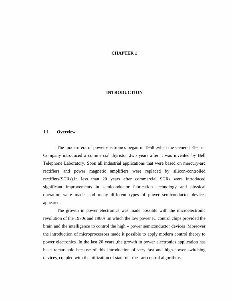
1.1 Overview
The modern era of power electronics began in 1958 ,when the General Electric
Company introduced a commercial thyristor ,two years after it was invented by Bell
Telephone Laboratory. Soon all industrial applications that were based on mercury-arc
rectifiers and power magnetic amplifiers were replaced by silicon-controlled
rectifiers(SCRs).In less than 20 years after commercial SCRs were introduced
significant improvements in semiconductor fabrication technology and physical
operation were made ,and many different types of power semiconductor devices
appeared.
The growth in power electronics was made possible with the microelectronic
revolution of the 1970s and 1980s ,in which the low power IC control chips provided the
brain and the intelligence to control the high – power semiconductor devices .Moreover
the introduction of microprocessors made it possible to apply modern control theory to
power electronics. In the last 20 years ,the growth in power electronics application has
been remarkable because of this introduction of very fast and high-power switching
devices, coupled with the utilization of state-of –the –art control algorithms.

2
An electric power can be converted from one form to another form by using
power electronics devices. The function of power electronics circuits by using
semiconductor devices as switch is modifying or controlling a voltage. The goal of
power electronics circuits are to convert electrical energy from one form to another,
from source to load with highest efficiency, high availability and high reliability with the
lowest cost, smallest size and weight.
There are four conversion circuits that are used in the majority of today’s power
electronics circuits. Firstly are ac-to-ac ,secondly is ac-to-dc ,thirdly is dc-to-ac and the
last is dc-to-dc.In terms of functional description ,modern power electronics system
perform one or more of the following conversion functions.
Figure 1.1 Four Types of Conversion
AACC ttoo DDCC:: RREECCTTIIFFIIEERR
DDCC ttoo DDCC:: CCHHOOPPPPEERR
DDCC ttoo AACC:: IINNVVEERRTTEERR
AACC ttoo AACC:: CCYYCCLLOOCCOONNVVEERRTTEERR

3
1.2 Background
Power electronic converters can be found wherever there is a need to modify the
electrical energy form (i.e modify its voltage, current or frequency). Therefore, their
power range from some milliwatts (as in a mobile phone) to hundreds of megawatts (e.g
in a HVDC transmission system). With "classical" electronics, electrical currents and
voltage are used to carry information, whereas with power electronics, they carry power.
Therefore the main metric of power electronics becomes the efficiency.
The first very high power electronic devices were mercury arc valves. In modern
systems the conversion is performed with semiconductor switching devices such as
diodes, thyristors and transistors. In contrast to electronic systems concerned with
transmission and processing of signals and data, in power electronics substantial
amounts of electrical energy are processed. An AC/DC converter (rectifier) is the most
typical power electronics device found in many consumer electronic devices, e.g.,
television sets, personal computers, battery chargers, etc. The power range is typically
from tens of watts to several hundred watts. In industry the most common application is
the variable speed drive (VSD) that is used to control an induction motor. The power
range of VSDs start from a few hundred watts and end at tens of megawatts.
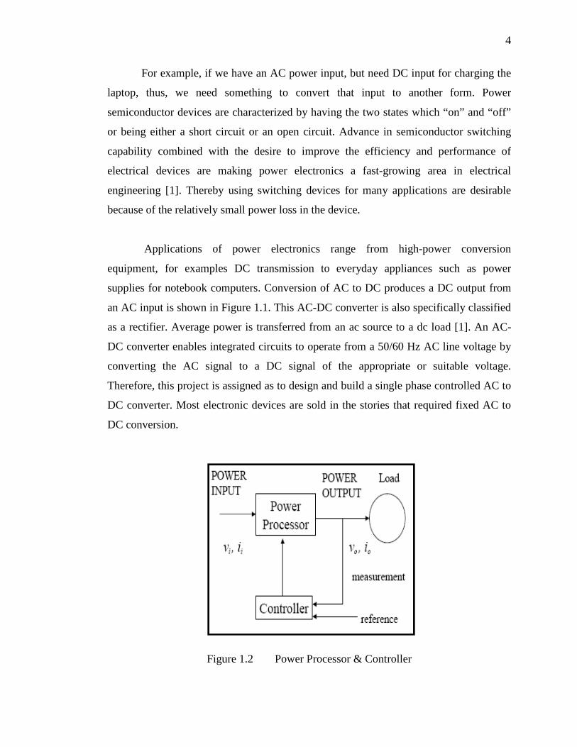
Most power electronics systems consist of two major modules as shown in
Figure 1.2 which are power electronics processor that handles power transfer from input
to output and controller that tells the power processor of what to do by taking the
measurement that happens at output and compared to input.
4
For example, if we have an AC power input, but need DC input for charging the
laptop, thus, we need something to convert that input to another form. Power
semiconductor devices are characterized by having the two states which “on” and “off”
or being either a short circuit or an open circuit. Advance in semiconductor switching
capability combined with the desire to improve the efficiency and performance of
electrical devices are making power electronics a fast-growing area in electrical
engineering [1]. Thereby using switching devices for many applications are desirable
because of the relatively small power loss in the device.
Applications of power electronics range from high-power conversion
equipment, for examples DC transmission to everyday appliances such as power
supplies for notebook computers. Conversion of AC to DC produces a DC output from
an AC input is shown in Figure 1.1. This AC-DC converter is also specifically classified
as a rectifier. Average power is transferred from an ac source to a dc load [1]. An AC-
DC converter enables integrated circuits to operate from a 50/60 Hz AC line voltage by
converting the AC signal to a DC signal of the appropriate or suitable voltage.
Therefore, this project is assigned as to design and build a single phase controlled AC to
DC converter. Most electronic devices are sold in the stories that required fixed AC to
DC conversion.
Figure 1.2 Power Processor & Controller
5
1.3 Objectives
The objective or the purpose of this project is the important part of getting started
because it will drive to the outcomes of this project.Basiclly there are two main purpose
which are ,firstly to explore and learn the operation of PIC16F84A to control thyristor
circuit and secondly to build and test the circuit to control variable speed DC motor.
Besides the two main objectives there are also others outcomes that need to be reach at
the end of this project such as to produce DC voltage or current with low ripple and to
produce the output close to the theoretical value.
1.4 Scopes
This project concentrates on a development of a circuit and hardware to get dc
output using SCR and PIC16F84A as main component of the project. Besides the
scopes is to program a microcontroller to control delay angle alfa and it produced
variable outputs (speed).
To develop the whole project, it consists of three methods which are the concept
of switching , the electrical structure, and the software programming.
After designing and building completely the rectifier circuit, the driver circuit
should be able to control the delay angle α, that can be adjusted by using
microcontroller. It will involve the programming development to control the ON state of
the power switch and adjust the phase angle. Here, the trigger angle of SCRs will be
programmed in certain time sequence to ensure the input voltage goes from low to full
voltage

6
1.4 Problem Statement
A rectifier is an electronic circuit that converts bidirectional voltage (AC
voltage) to unidirectional voltage (DC voltage) by using power diodes or by controlling
the firing angle of thyristor/controllable switches. Rectifier usually can be divided into
two types that are uncontrolled and phase-controlled. Each type can have either single-
phase or three-phase. A diode is the simplest electronics switch which it is uncontrolled
that the on and off states can be determined by the power supply in the circuit itself. AC
to DC converter is mostly used in industries and also in domestic equipment. But many
rectifiers in the market only produce fixed output so the applications of the rectifiers are
limited for certain equipment only. So, the DC level of the output and the power
transferred to the load are fixed when the source and load parameters are established.
Hence, to overcome this problem there is a way to control the output voltage of
the rectifier. Basically, the single phase rectifier is designed using the thyristors or more
specifically are called Silicon Control Rectifier (SCR) which connected in full-wave
rectifier. A thyristor is four layers (pnpn) semiconductor devices that act as switches,
rectifiers or voltage regulators. Thyristors are electronic switches used in power
electronics circuits where control of switch turn-on is required [1]. Thus, the output
voltage can be variable from the range of zero voltage to full voltage by controlling the
delay angle of the SCR.

7
1.5 Thesis Outline
There are all five chapters being structures in this thesis and every chapter will
elaborate in detail about this project. For the first chapter, an overview about this project,
single phase controlled rectifier is discussed including the objectives and scopes of the
project as a guide to develop the single phase controlled rectifier.
Chapter 2 will explain and discuss on the literature review of the single phase
controlled rectifier. It also focuses on general introduction of the AC to DC converter
with the complete information about this converter. It gives a brief review about the
types of the rectifiers: uncontrolled and controlled single phase and three phase
converters used as rectifiers. In this chapter also discuss about the type of thyristor and
the characteristic of each type.
Chapter 3 discusses the methodologies of the single phase controlled rectifier
that has been applied in completing this project. In this chapter, it consists of block
diagram and flow chart which are explained about the process of implementation and
how the AC voltage converts to DC voltage then connected to the load such as DC
motor. It is also discusses briefly how the output voltage can be varied.
Chapter 4 is discussing and displaying all the results obtained and the limitation
of the project. All discussions are concentrated on the result and the overall performance
of the single phase controlled rectifier.
Chapter 5 in overall will discuss on the conclusion and summary of the
development of the single phase controlled rectifier completed project. In this chapter
also discusses on the problems and recommendation for this project development or
modification.

CHAPTER 2
LITERATURE REVIEW
2.1 Introduction
The literature review about this project have been made from various sources
like journals, books, articles and others. From the literature review ,the input that have
been collected is useful for better understanding of this project. It is because for nearly a
century, rectifier circuits have been the most common power electronics circuits used to
convert AC to DC. The AC-DC converter produces a DC output from an AC input while
the average power transferred from an AC source to a DC load. This converter usually
also called as a rectifier. The word rectification is used not because these circuits
produce DC but rather because the current flows in one direction. Generally, there are
two types of AC-DC converters which are uncontrolled and controlled. The input of
these converters can be single phase or multi-phase (3 phase).

9
2.2 Uncontrolled Single Phase Rectifier
This type of rectifier consists of half-wave rectification and full-wave
rectification. Uncontrolled rectifiers make use of diodes. Diodes are two-terminal
semiconductor devices that allow flow of current in only one direction. The two
terminals of a diode are known as the anode and the cathode. The designs are cheap and
popular in the industrial applications. In some of these rectifiers, the AC source from the
electric utility is directly rectified without using of an expensive and bulky transformer.
In some applications, the DC voltage from the rectifier is connected to a DC bus for
distribution to several different circuit systems, subsystems and other converters as loads
[10]. In other applications, the rectifiers also supply power to inductive-resistive
(motors) and capacitive-resistive (power supplies) loads.
2.2.1 Single Phase Half-Wave Rectifiers
The simplest of the rectifier circuit is a single phase half-wave rectifier consists
of a single diode as shown in Figure 2.1. A diode is the simplest electronic switch. It is
uncontrolled in that the on and off conditions are determined by voltages and currents in
the circuit [1]. By using diode, the DC level of the output and the power transferred to
the load are fixed when the source and load parameters are established. It produces an
output waveform that is half of the incoming AC voltage waveform.
The positive pulse output waveform occurs because of the forward-biased
condition of the diode. A diode experiences a forward-biased condition when its anode
is at a higher potential than its cathode. Reverse bias occurs when its anode is lower than

10
its cathode. During the positive portion of the input waveform, the diode becomes
forward biased, which allows current to pass through the diode from anode to cathode,
such that it flows through the load to produce a positive output pulse waveform. Over
the negative portion of the input waveform, the diode is reverse-biased ideally so no
current flows. Thus, the output waveform is zero or nearly zero during this portion of the
input waveform.
Figure 2.1 Single Phase Half-Wave Rectifier
2.2.2 Single Phase Full-Wave Rectifiers
The purpose of the full-wave rectifier is basically the same as that of the half-
wave rectifier but full-wave rectifiers have some fundamental advantages. There are two
types of full-wave rectifiers that are the bridge rectifier and the center-tapped rectifier as
shown in Figure 2.2 and Figure 2.3.
Figure 2.2 The Bridge Rectifier

11
Figure 2.3 The Center-Tapped Transformer Rectifier
The lower peak diode voltage in the bridge rectifier which consists of four diodes
arranged makes it more suitable for high-voltage applications. Thus, the center-tapped
transformer rectifier in addition to including electrical isolation has only one diode
voltage drop between the source and load making it desirable for low-voltage and high
current applications.
2.3 Controlled Single Phase Rectifier
The previous rectifiers are classified as uncontrolled rectifiers but once the
source and the load parameters are established, the DC level of the output and the power
transferred to the load are fixed quantities. As mentioned before that the output voltage
of the AC-DC converters using diodes is not controllable because the diodes are not self-
controlled switch [10]. Thus, there is a way to control the output by using thyristor
instead of a diode. A thyristor is a four-layer (pnpn), three-junction device that conducts
current only in one direction similar to a diode.
12
2.3.1 Single Phase Half-Wave Rectifiers
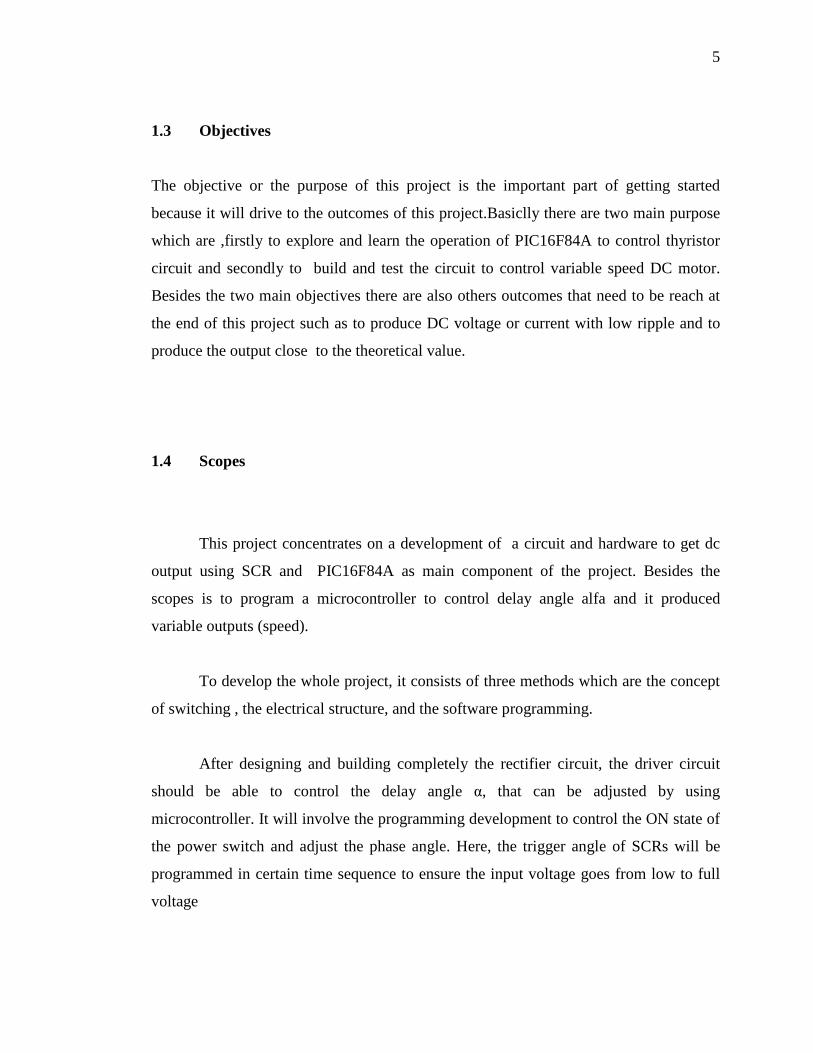
Unlike the diode, the silicon controlled rectifier (SCR) will not to begin to
conduct as soon as the source becomes positive [1]. Gate trigger current is the minimum
current required to switch silicon controlled rectifiers from the off-state to the on-state at
the specified off-state voltage and temperature. Once the SCR is conducting, the gate
current can be removed and the SCR remains on until the current goes to zero [1]. Figure
2.4 shows a basic controlled half-wave rectifier.
Figure 2.4 A Basic Half-Wave Controlled Rectifier

13
2.3.2 Single Phase Full-Wave Rectifiers
Popular AC-DC converters use full-bridge topologies [10]. Full-bridge
converters are designed for delivering constant but controllable DC current or DC
voltage to the load. Similar to the diode bridge rectifier topology, a versatile method of
controlling the output of a full-wave rectifier is to substitute controlled switches such as
SCRs for the diode. Because of their unique ability to be controlled, the output voltage
and hence the power can be controlled to desire levels. The triggering of the thyristor
has to be synchronized with the input sinusoidal voltage in an AC to DC rectifier circuit.
The delay angle α is the angle interval between the forward biasing of the SCR and the
gate signal application [1]. Otherwise, if the delay angle is zero, the rectifiers behave
exactly like uncontrolled rectifiers with diodes. Figure 2.5 shows a basic controlled full-
wave rectifier.
Figure 2.5 A Basic Full-Wave Controlled Bridge Rectifier
14
2.3.3 Phase Angle Delay Control
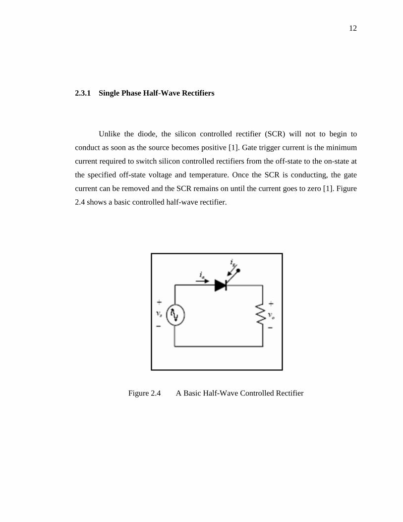
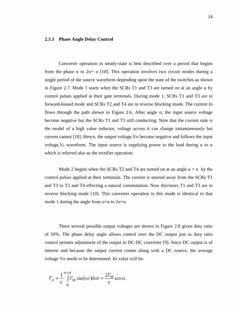
Converter operation in steady-state is best described over a period that begins
from the phase α to 2п+ α [10]. This operation involves two circuit modes during a
single period of the source waveform depending upon the state of the switches as shown
in Figure 2.7. Mode 1 starts when the SCRs T1 and T3 are turned on at an angle α by
control pulses applied at their gate terminals. During mode 1, SCRs T1 and T3 are in
forward-biased mode and SCRs T2 and T4 are in reverse blocking mode. The current Io
flows through the path shown in Figure 2.6. After angle п, the input source voltage
become negative but the SCRs T1 and T3 still conducting. Note that the current sink is
the model of a high value inductor, voltage across it can change instantaneously but
current cannot [10]. Hence, the output voltage,Vo become negative and follows the input
voltage,Vs waveform. The input source is supplying power to the load during α to п
which is referred also as the rectifier operation.
Mode 2 begins when the SCRs T2 and T4 are turned on at an angle α + п by the
control pulses applied at their terminals. The current is steered away from the SCRs T1
and T3 to T2 and T4 effecting a natural commutation. Now thyristors T1 and T3 are in
reverse blocking mode [10]. This converter operation in this mode is identical to that
mode 1 during the angle from п+α to 2п+α.
There several possible output voltages are shown in Figure 2.8 given duty ratio
of 50%. The phase delay angle allows control over the DC output just as duty ratio
control permits adjustment of the output in DC-DC converter [9]. Since DC output is of
interest and because the output current comes along with a DC source, the average
voltage Vo needs to be determined. Its value will be:

15
Figure 2.6 Circuit Modes
Figure 2.7 Possible Output Voltage waveform For SCR Bridge
(a)
(e)
(b)
(c)
(f)
(d)
16
2.4 Three Phase Rectifiers
Three phase rectifiers are more commonly used because of the following
reasons: [8]
i. Three phase AC power is readily available.
ii. It is economical to provide DC supply to DC motors of capacity 20kW and more
from a three phase rectifier rather than single phase.
iii. The ripple frequency of the output current of the three phase rectifiers is higher
than that for single phase ones.
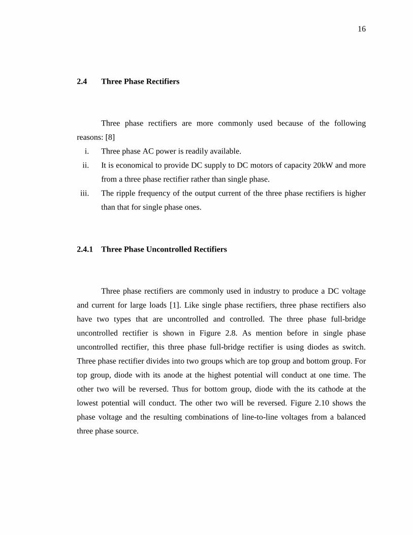
2.4.1 Three Phase Uncontrolled Rectifiers
Three phase rectifiers are commonly used in industry to produce a DC voltage
and current for large loads [1]. Like single phase rectifiers, three phase rectifiers also
have two types that are uncontrolled and controlled. The three phase full-bridge
uncontrolled rectifier is shown in Figure 2.8. As mention before in single phase
uncontrolled rectifier, this three phase full-bridge rectifier is using diodes as switch.
Three phase rectifier divides into two groups which are top group and bottom group. For
top group, diode with its anode at the highest potential will conduct at one time. The
other two will be reversed. Thus for bottom group, diode with the its cathode at the
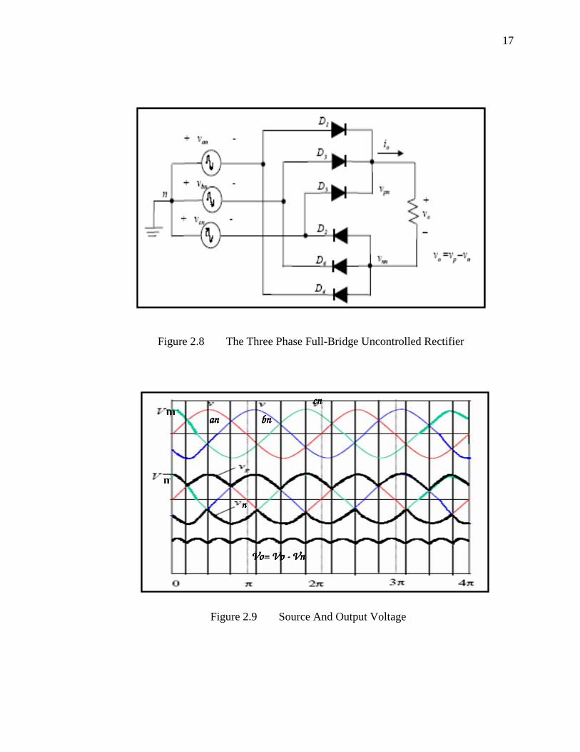
lowest potential will conduct. The other two will be reversed. Figure 2.10 shows the
phase voltage and the resulting combinations of line-to-line voltages from a balanced
three phase source.
17
Figure 2.8 The Three Phase Full-Bridge Uncontrolled Rectifier
Figure 2.9 Source And Output Voltage
m anananan bnbnbnbn
cncncncn
m
nnnn
Vo= Vp Vo= Vp Vo= Vp Vo= Vp ---- Vn Vn Vn Vn

18
2.4.2 Three phase Controlled Rectifiers
Similar to single phase controlled rectifier, the output of the three phase rectifier
can be controlled by substituting SCRs for diodes. Figure 2.10 shows a controlled six-
pulse three phase rectifier. As mention before in single phase controlled rectifier, SCRs
will conduct until a gate signal is applied while the SCR is forward biased. Thus, the
transition of the output voltage to the maximum instantaneous line-to-line source voltage
can be delayed [1].
Figure 2.10 The Three Phase Full-Bridge Controlled Rectifier

19
2.5 Types of Thyristor 2.5.1 Silicon Controlled Rectifier
The thyristor is a solid-state semiconductor device with four layers of alternating
N and P-type material. They act as a switch, conducting when their gate receives a
current pulse, and continue to conduct for as long as they are forward biased (that is, as
long as the voltage across the device has not reversed).
Some sources define silicon controlled rectifiers and thyristors as synonymous;
others define SCRs as a subset of thyristors, along with gate turn-off thyristor (GTO),
triode ac switch (triac), static induction transistor (SIT), static induction thyristor (SITH)
and MOS-controlled thyristor (MCT). Among the latter, the International Electro
technical Commission 60747-6 standard stands out.
Non-SCR thyristors include devices with more than four layers, such as triacs and DB-
GTOs.
Function
The thyristor is a four-layer semiconducting device, with each layer consisting of
alternately N-type or P-type material, for example P-N-P-N. The main terminals, labeled
anode and cathode, are across the full four layers, and the control terminal, called the
gate, is attached to p-type material near to the cathode. (A variant called an SCS Silicon
Controlled Switch brings all four layers out to terminals.) The operation of a thyristor
can be understood in terms of a pair of tightly coupled Bipolar Junction Transistors,
arranged to cause the self-latching action:
20
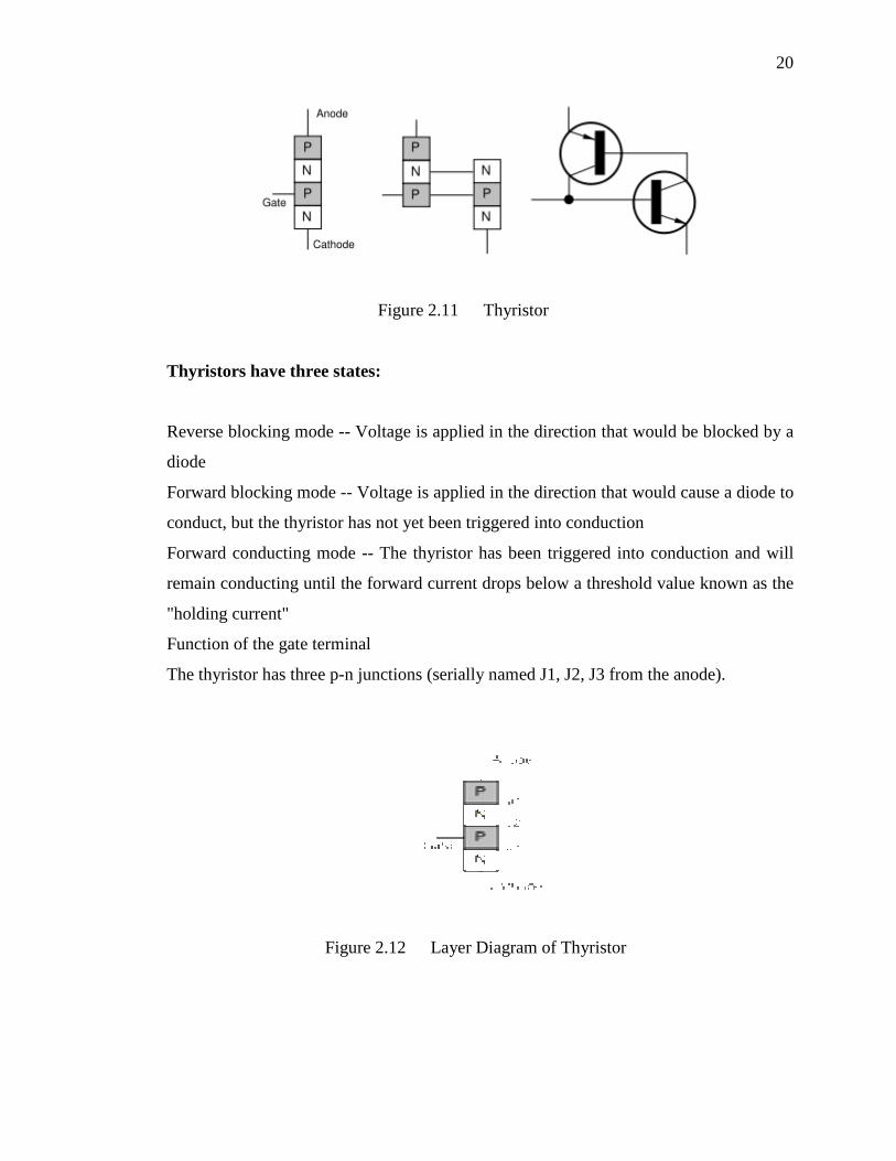
Figure 2.11 Thyristor
Thyristors have three states:
Reverse blocking mode -- Voltage is applied in the direction that would be blocked by a
diode
Forward blocking mode -- Voltage is applied in the direction that would cause a diode to
conduct, but the thyristor has not yet been triggered into conduction
Forward conducting mode -- The thyristor has been triggered into conduction and will
remain conducting until the forward current drops below a threshold value known as the
"holding current"
Function of the gate terminal
The thyristor has three p-n junctions (serially named J1, J2, J3 from the anode).
Figure 2.12 Layer Diagram of Thyristor

21
When the anode is at a positive potential VAK with respect to the cathode with
no voltage applied at the gate, junctions J1 and J3 are forward biased, while junction J2
is reverse biased. As J2 is reverse biased, no conduction takes place (Off state). Now if
VAK is increased beyond the breakdown voltage VBO of the thyristor, avalanche
breakdown of J2 takes place and the thyristor starts conducting (On state).
If a positive potential VG is applied at the gate terminal with respect to the
cathode, the breakdown of the junction J2 occurs at a lower value of VAK. By selecting
an appropriate value of VG, the thyristor can be switched into the on state
immediately.It should be noted that once avalanche breakdown has occurred, the
thyristor continues to conduct, irrespective of the gate voltage, until either: (a) the
potential VG is removed or (b) the current through the device (anode−cathode) is less
than the holding current specified by the manufacturer. Hence VG can be a voltage
pulse, such as the voltage output from a UJT relaxation oscillator.
These gate pulses are characterized in terms of gate trigger voltage (VGT) and
gate trigger current (IGT). Gate trigger current varies inversely with gate pulse width in
such a way that it is evident that there is a minimum gate charge required to trigger the
thyristor.
Switching characteristics
In a conventional thyristor, once it has been switched on by the gate terminal, the
device remains latched in the on-state (i.e. does not need a continuous supply of gate
current to conduct), providing the anode current has exceeded the latching current (IL).
As long as the anode remains positively biased, it cannot be switched off until the anode
current falls below the holding current (IH).

22
Figure 2.13 V - I Characteristics
A thyristor can be switched off if the external circuit causes the anode to become
negatively biased. In some applications this is done by switching a second thyristor to
discharge a capacitor into the cathode of the first thyristor. This method is called forced
commutation.
After a thyristor has been switched off by forced commutation, a finite time
delay must have elapsed before the anode can be positively biased in the off-state. This
minimum delay is called the circuit commutated turn off time (tQ). Attempting to
positively bias the anode within this time causes the thyristor to be self-triggered by the
remaining charge carriers (holes and electrons) that have not yet recombined.
For applications with frequencies higher than the domestic AC mains supply (e.g. 50 Hz
or 60 Hz), thyristors with lower values of tQ are required. Such fast thyristors are made
by diffusing into the silicon heavy metals ions such as gold or platinum which act as
charge combination centers. Alternatively, fast thyristors may be made by neutron
irradiation of the silicon.

23
History
1956 The Silicon Controlled Rectifier (SCR) or Thyristor proposed by William
Shockley in 1950 and championed by Moll and others at Bell Labs was developed first
by power engineers at General Electric (G.E.) led by Gordon Hall and commercialized
by G.E.'s Frank W. "Bill" Gutzwiller.
Application
Figure 2.14 A bank of six, 2000 A Thyristors (white pucks).
The clear tubes are for cooling water
Thyristors are mainly used where high currents and voltages are involved, and
are often used to control alternating currents, where the change of polarity of the current
causes the device to automatically switch off; referred to as Zero Cross operation. The
device can be said to operate synchronously as, once the device is open, it conducts
current in phase with the voltage applied over its cathode to anode junction with no
further gate modulation being required to replicate; the device is biased fully on. This is
not to be confused with symmetrical operation, as the output is unidirectional, flowing
only from cathode to anode, and so is asymmetrical in nature.Thyristors can be used as
the control elements for phase angle triggered controllers, also known as phase fired
controllers.
24
Thyristors can also be found in power supplies for digital circuits, where they
can be used as a sort of "circuit breaker" or "crowbar" to prevent a failure in the power
supply from damaging downstream components. The thyristor is used in conjunction
with a zener diode attached to its gate, and when the output voltage of the supply rises
above the zener voltage, the thyristor conducts, shorting the power supply output to
ground (and in general blowing an upstream fuse).
The first large scale application of thyristors, with associated triggering diac, in
consumer products related to stabilized power supplies within color television receivers
in the early 1970s. The stabilized high voltage DC supply for the receiver was obtained
by moving the switching point of the thyristor device up and down the falling slope of
the positive going half of the AC supply input (if the rising slope was used the output
voltage would always rise towards the peak input voltage when the device was triggered
and thus defeat the aim of regulation).
The precise switching point was determined by the load on the output d.c. supply
as well fluctuations on the input a.c. supply. They proved to be unpopular with the a.c.
grid power supplier companies because the simultaneous switching of many television
receivers, all at approximately the same time, introduced asymmetry into the supply
waveform and, as a consequence injected d.c. back into the grid with a tendency towards
saturation of transformer cores and overheating. Thyristors were largely phased out in
this kind of application by the end of the decade.
Thyristors have been used for decades as lighting dimmers in television, motion
pictures, and theater, where they replaced inferior technologies such as autotransformers
and rheostats. They have also been used in photography as a critical part of flashes
(strobes).